Embed Size (px)
Citation preview

1/58
Components of solar systems
storage
heat exchangers
safety and protection devices
air vents, check valve
control & measurement
self-study

2/58
Thermosiphon circulation system
circulation induced by
buoyancy effect
Principle: difference in densities
(temperatures) of fluid
water density: 20 °C is 998 kg/m3
80 °C only 972 kg/m3
…. Dif .. 26 kg/m3
self-controlled system
higher temperature in collector –
higher circulation (flowrate)
3/58
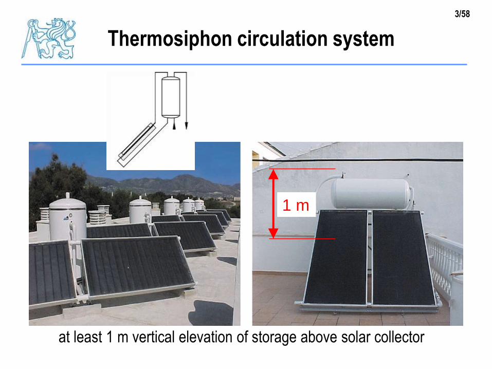
Thermosiphon circulation system
1 m
at least 1 m vertical elevation of storage above solar collector
4/58
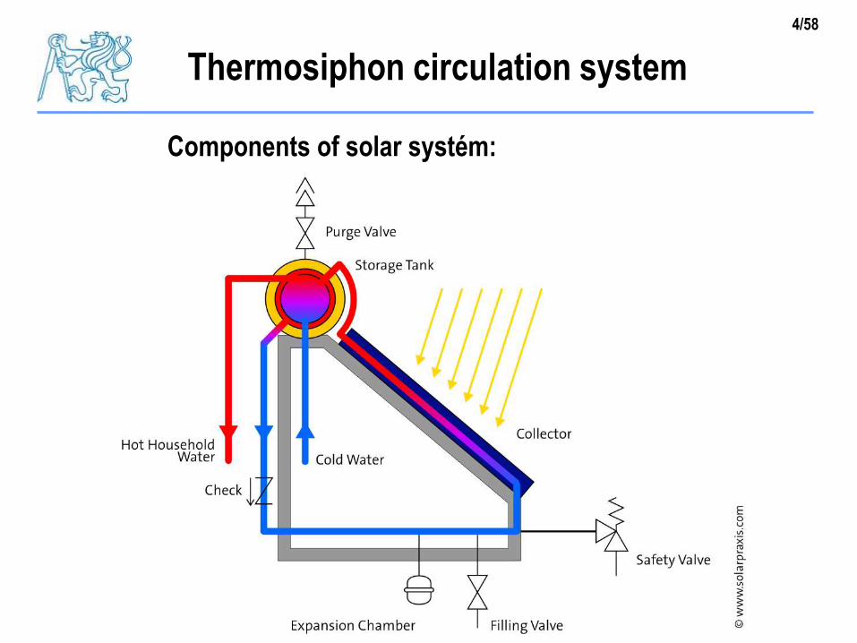
Components of solar systém:
Thermosiphon circulation system

5/58
Forced circulation system
circulation induced by pump
collector could be above
storage
no limits
electronic controller
measurement of
temperature difference
between collector and
storage – signal for
switching the pump on/off

6/58
Components of solar system
safety
valve
expansion
vessel
check
valveheat
exchanger
pipes,
insulation
storage
tank
7/58
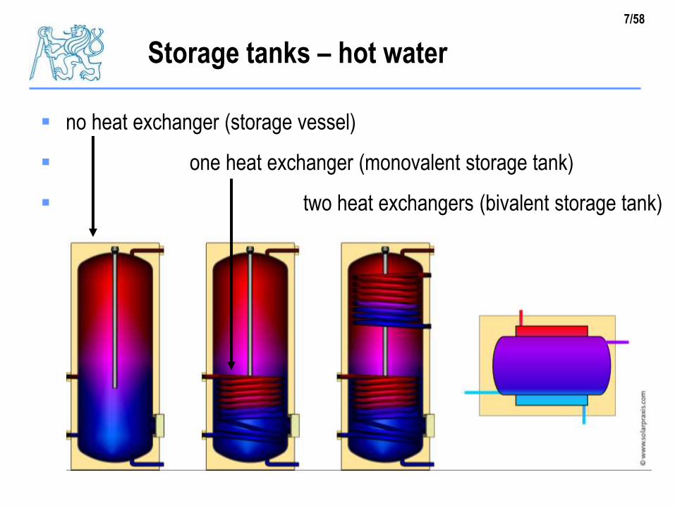
Storage tanks – hot water
no heat exchanger (storage vessel)
one heat exchanger (monovalent storage tank)
two heat exchangers (bivalent storage tank)

8/58
Storage tanks – combined with SH (space heating)
small heat
transfer area
small loads
1 – 2 persons
double small heat
transfer surface
higher loads
3 – 4 persons
tank in tank
(DHW tank in SH tank)with tube heat exchanger
(DHW heat exchanger
in SH tank)
9/58
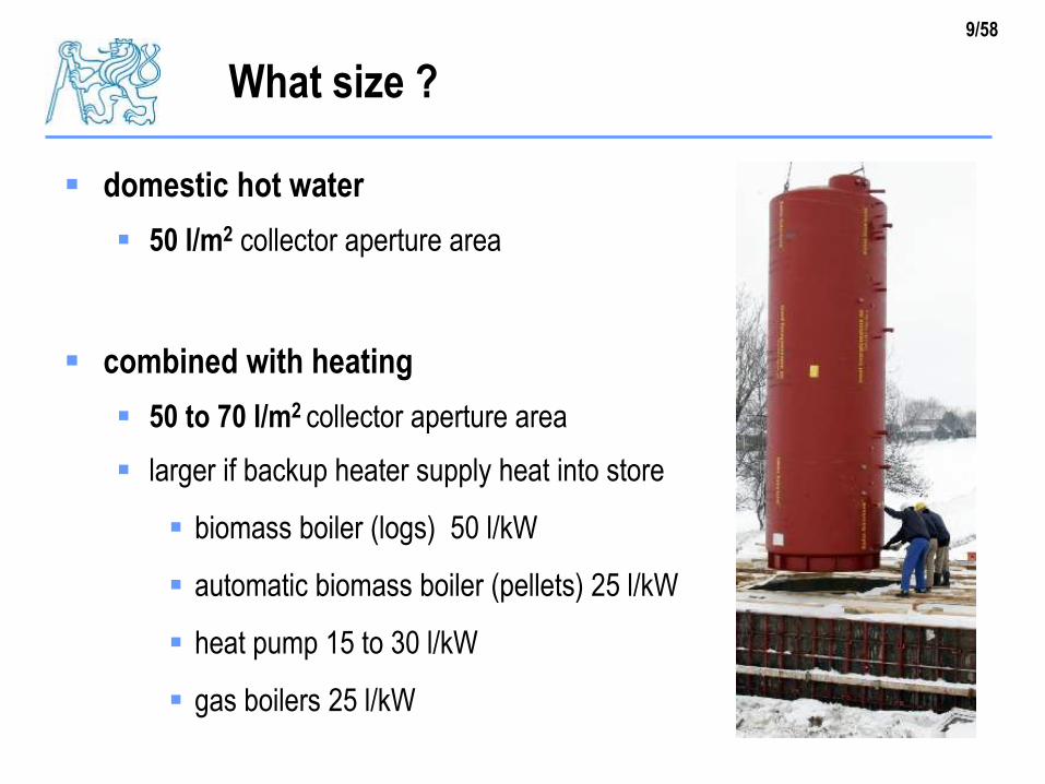
What size ?
domestic hot water
50 l/m2 collector aperture area
combined with heating
50 to 70 l/m2 collector aperture area
larger if backup heater supply heat into store
biomass boiler (logs) 50 l/kW
automatic biomass boiler (pellets) 25 l/kW
heat pump 15 to 30 l/kW
gas boilers 25 l/kW

10/58
What size ? EXAMPLE
solar combitank
one tank for solar system and back-up
one tank for DHW and SH
example
biomass boiler 10 kW
solar system 10 m2 10 m2 x 50 l
= 500 l
boiler
11/58
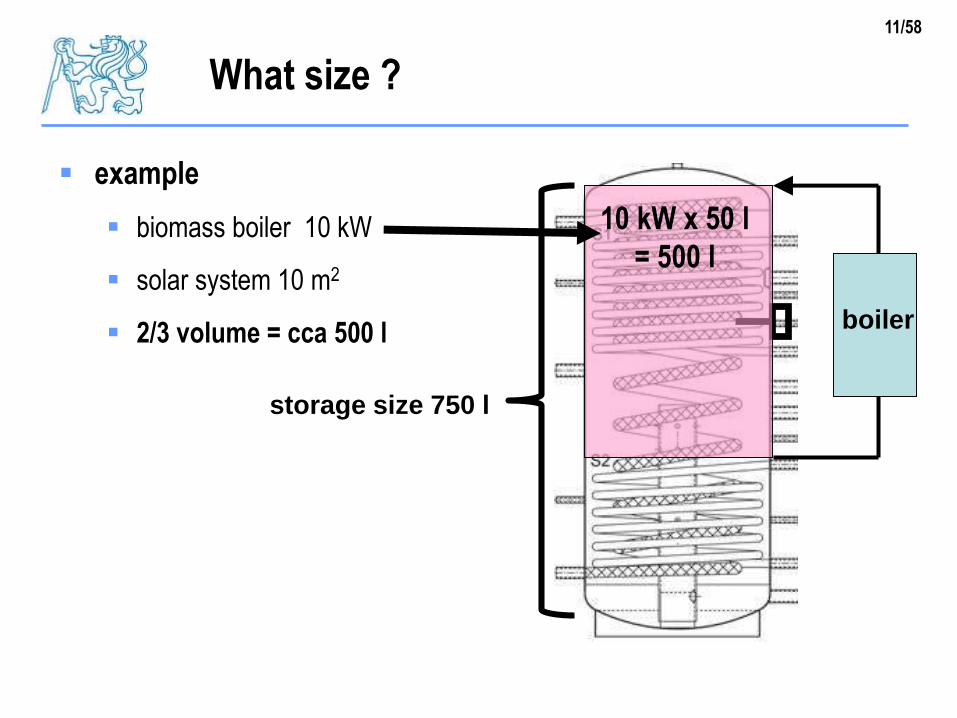
What size ?
example
biomass boiler 10 kW
solar system 10 m2
2/3 volume = cca 500 l
10 kW x 50 l
= 500 l
boiler
storage size 750 l

12/58
Exergy
usability of stored heat ~ usable temperature
thermal stratification = higher efficiency, higher solar fraction
stratified storage mixed storage

13/58
Factors influencing stratification
aspect ratio of tank: Height / Diameter (slim tank… better stratificaion)
heat input (stratified input is better than fixed)
cold water input (in bottom, prevented mixing)
return flow from heating system input (stratified is better than fixed)
heat loss of storage, thermal bridges – make worst strafication
stratification devices (for development of stratified volume)
14/58
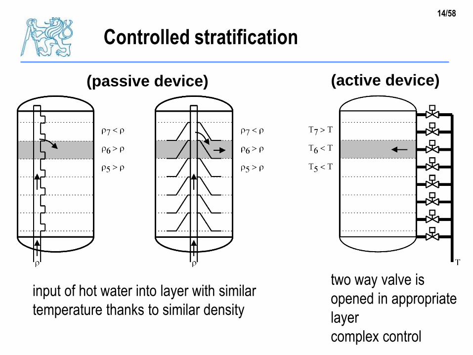
Controlled stratification
two way valve is
opened in appropriate
layer
complex control
input of hot water into layer with similar
temperature thanks to similar density
(passive device) (active device)

15/58
Stratification devices in combined tank
insulation
external DHW heat exchanger
piping
stratified SH return flow
stratification device with integrated heat
exchanger HX
input of cooled water from DHW heat
exchanger
SOL SH
CW
DHW
adaptable flowrate (controlled)

16/58
tube heat exchanger immersed in the tank
U-values = 120 to 300 W/m2K (thermal transmittance)
(laminar flow, natural convection) 0.4 m2 ribbed tubes / m2 col.area, 0.2 m2 bare exchange tubes / m2 col.area
Heat exchangers (internal)
for small
systems < 20 m2
17/58
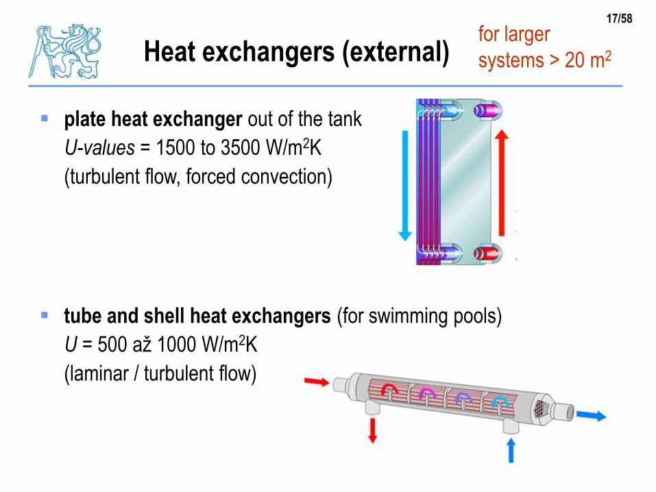
plate heat exchanger out of the tank
U-values = 1500 to 3500 W/m2K
(turbulent flow, forced convection)
tube and shell heat exchangers (for swimming pools)
U = 500 až 1000 W/m2K
(laminar / turbulent flow) 0.05 to 0.08 m2 exchange area / m2 col.area
Heat exchangers (external)for larger
systems > 20 m2
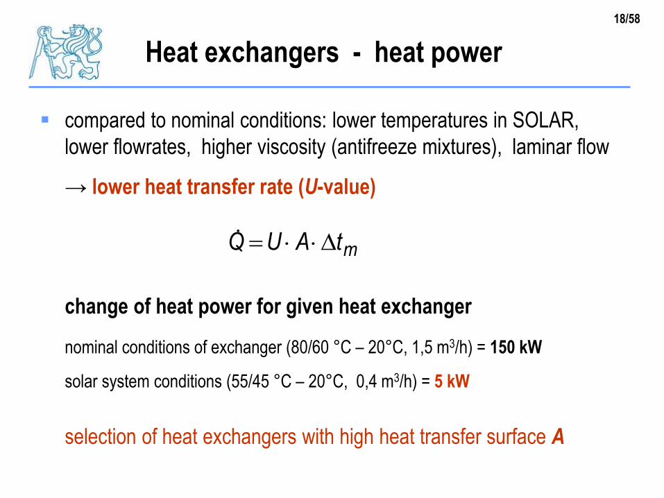
18/58
compared to nominal conditions: lower temperatures in SOLAR,
lower flowrates, higher viscosity (antifreeze mixtures), laminar flow
→ lower heat transfer rate (U-value)
change of heat power for given heat exchanger
nominal conditions of exchanger (80/60 °C – 20°C, 1,5 m3/h) = 150 kW
solar system conditions (55/45 °C – 20°C, 0,4 m3/h) = 5 kW
selection of heat exchangers with high heat transfer surface A
Heat exchangers - heat power
mtAUQ

19/58
Plate heat exchangers
50 °C
25 °C
48 °C
20 °C
Q = 26 kW
1000 l/h 900 l/h
U = 2000 W/m2K
A = 4 m2
50 °C
34 °C
38 °C
20 °C
Q = 17 kW
1000 l/h 900 l/h
U = 1000 W/m2K
A = 1.3 m2
93 % 60 %
tm = 3.3 K tm = 13 Ktm Arithmetic Mean Temperature Difference
= (tpi + tpo) / 2 - (tsi + tso) / 2
20/58
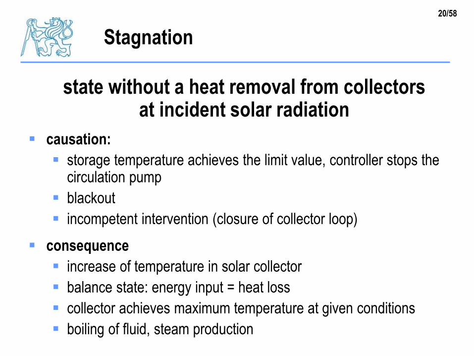
Stagnation
state without a heat removal from collectorsat incident solar radiation
causation:
storage temperature achieves the limit value, controller stops thecirculation pump
blackout
incompetent intervention (closure of collector loop)
consequence
increase of temperature in solar collector
balance state: energy input = heat loss
collector achieves maximum temperature at given conditions
boiling of fluid, steam production
21/58
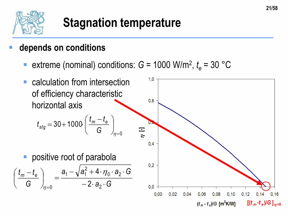
Stagnation temperature
depends on conditions
extreme (nominal) conditions: G = 1000 W/m2, te = 30 °C
calculation from intersection
of efficiency characteristic with
horizontal axis
positive root of parabola
0
100030
G
ttt emstg
Ga
Gaaa
G
tt em
2
20211
0 2
4
22/58
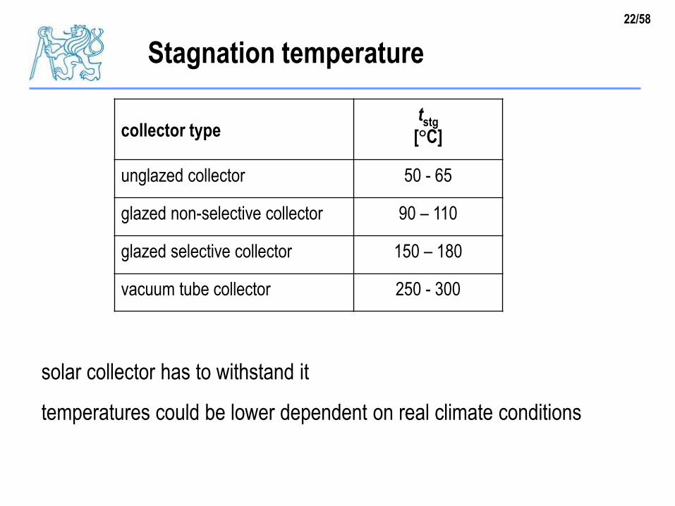
Stagnation temperature
collector typetstg
[°C]
unglazed collector 50 - 65
glazed non-selective collector 90 – 110
glazed selective collector 150 – 180
vacuum tube collector 250 - 300
solar collector has to withstand it
temperatures could be lower dependent on real climate conditions
23/58
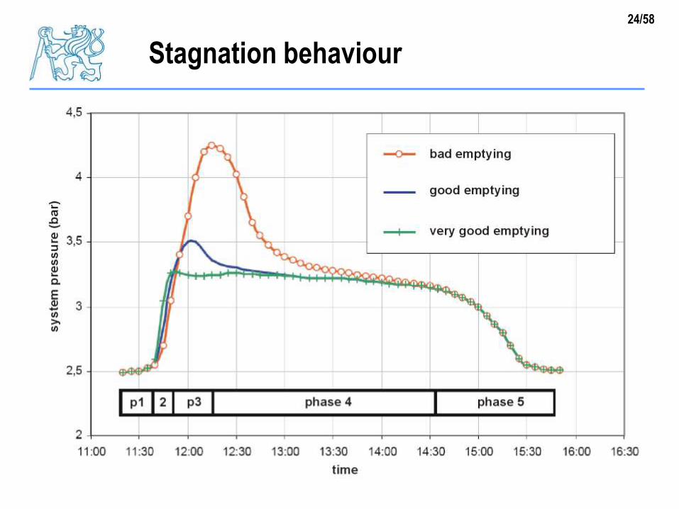
Stagnation behaviour
Phase1: liquid is expanding
Phase2: achieves boiling point (at given pressure), boiling starts
first bubbles appear, saturated steam, liquid is expelled fromcollector
Phase3: rest of liquid is transformed in steam
volume of collector is filled by steam, high heat removal
Phase4: superheating of steam in collector
emptying of collector, stable state, collector full of steam
Phase5: decrease of radiation, decrease of temperature
condensation, liquid phase fills up the collector back
24/58
Stagnation behaviour
25/58
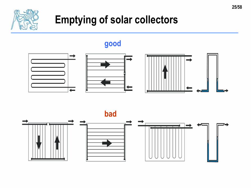
Emptying of solar collectors
good
bad

26/58
Types of solar liquids
water
nontoxic, nonflammable, cheap, high thermal capacity, low
viscosity
limited usable temperature range (seasonal systems),
ethylenglycol
antifreeze mixture with water, toxic, low viscosity
propylenglycol
antifreeze mixture with water, high viscosity dependent on
temperature, low thermal capacity (lower by 20 % than water),
corrosion inhibitors, stabilisers and other additives

27/58
Properties of propylenglycol-water
density specific heat
dynamic viscosity thermal expansion
http://www.mrc-eng.com/Downloads/Brine%20Properties.pdf

28/58
Kinematic viscosity
0
1
2
3
4
5
6
7
20 40 60 80 100
t [°C]
[mm2/s]
propylenglykol+voda
voda
Propylenglycol has higher viscosity,
laminar flow, so friction losses
significant dependence of viscosity on
temperature
change of hydraulics during operation
Prophylenglycol+water.. -30°C
water
29/58
Piping and thermal insulation
durability
resistant to pressures and temperatures
ageing, atmospheric conditions
energy performance
piping – low pressure loss, consumption of electricity for pumps
thermal insulation – low heat loss, efficiency and gains of solar
system, use of back-up heating

30/58
Materials for pipes
plastic pipes
EPDM, UV protection, only swimming pools
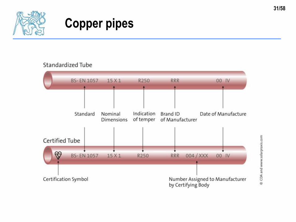
copper pipes
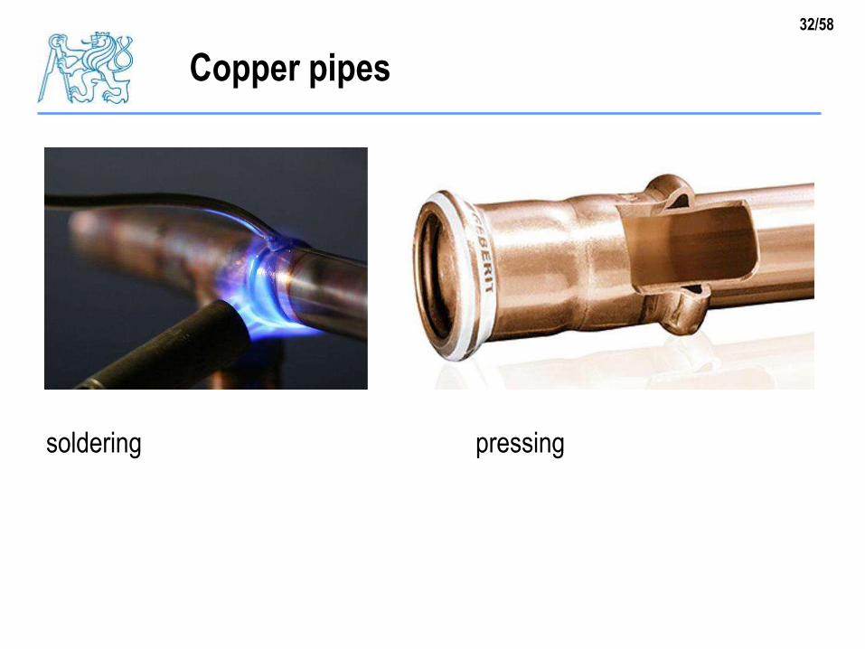
easy connections, soldering, pressing, same material as
collectors, zero electro/chemical potential (low corrosion)
steel pipes
welding, complicated assembly, low price!
stainless steel (corrugated)
easy assembly, formable, also for heat exchangers
31/58
Copper pipes
32/58
Copper pipes
soldering pressing

33/58
Steel pipes
34/58
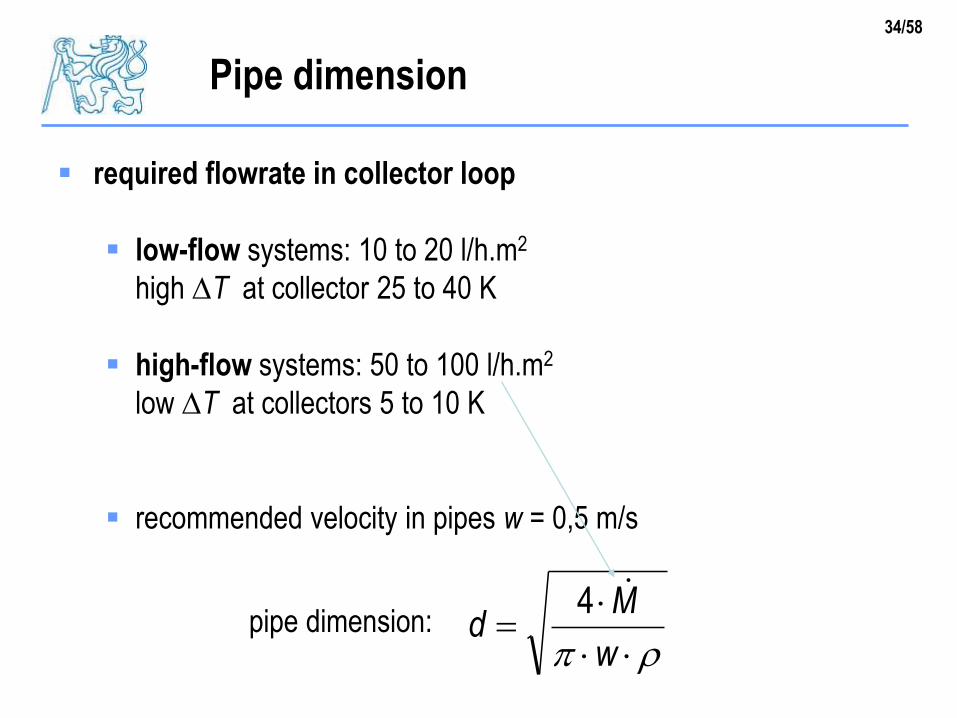
Pipe dimension
required flowrate in collector loop
low-flow systems: 10 to 20 l/h.m2
high T at collector 25 to 40 K
high-flow systems: 50 to 100 l/h.m2
low T at collectors 5 to 10 K
recommended velocity in pipes w = 0,5 m/s
pipe dimension:
w
Md
4
35/58
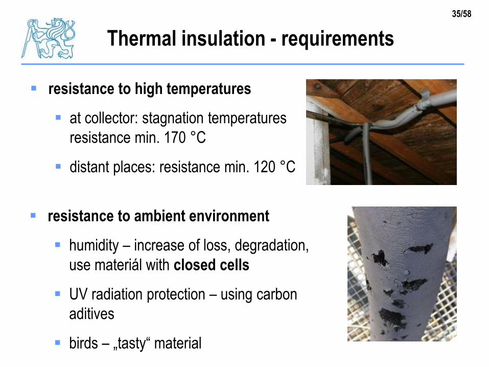
Thermal insulation - requirements
resistance to ambient environment
humidity – increase of loss, degradation,
use materiál with closed cells
UV radiation protection – using carbon
aditives
birds – „tasty“ material
resistance to high temperatures
at collector: stagnation temperatures
resistance min. 170 °C
distant places: resistance min. 120 °C

36/58
Materials for thermal insulation
EPDM foams, syntetic rubber
(+) low thermal conductivity
(+) closed structure
(0) UV protection
(–) „tasty“ material for birds
resistance:
170 °C short-term
130 °C long-term
37/58
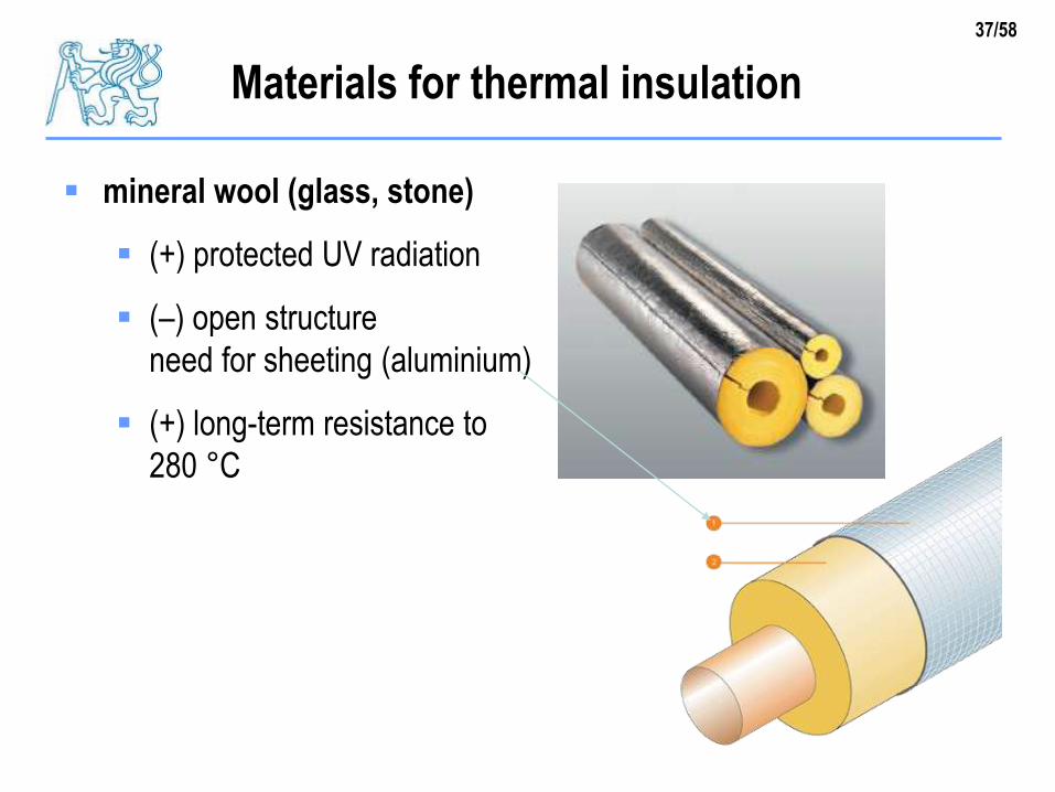
Materials for thermal insulation
mineral wool (glass, stone)
(+) protected UV radiation
(–) open structure
need for sheeting (aluminium)
(+) long-term resistance to
280 °C
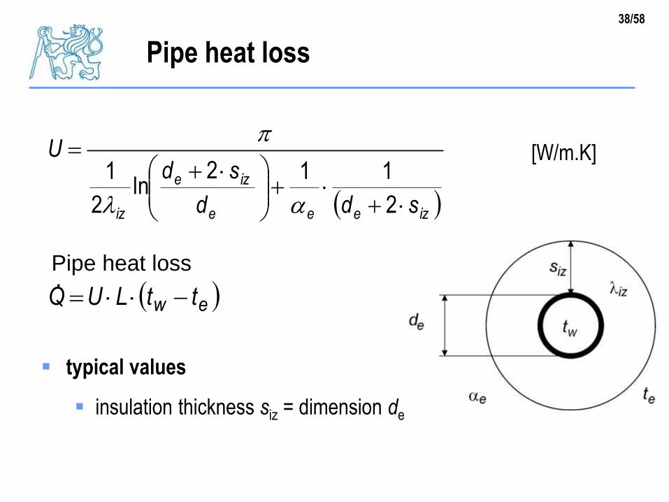
38/58
Pipe heat loss
izeee
ize
iz sdd
sdU
2
112ln
2
1
ew ttLUQ
[W/m.K]
typical values
insulation thickness siz = dimension de
Pipe heat loss

39/58
Insulated piping

40/58
Safety and protection devices
expansion vessel
allows the changes of fluid volume (due to thermal expansion)
without extreme increase of pressure above non-perimissible
limit
safety valve
protects the collector loop against non-permissible pressure
safety valve will not react during standard operation
even in case of stagnation
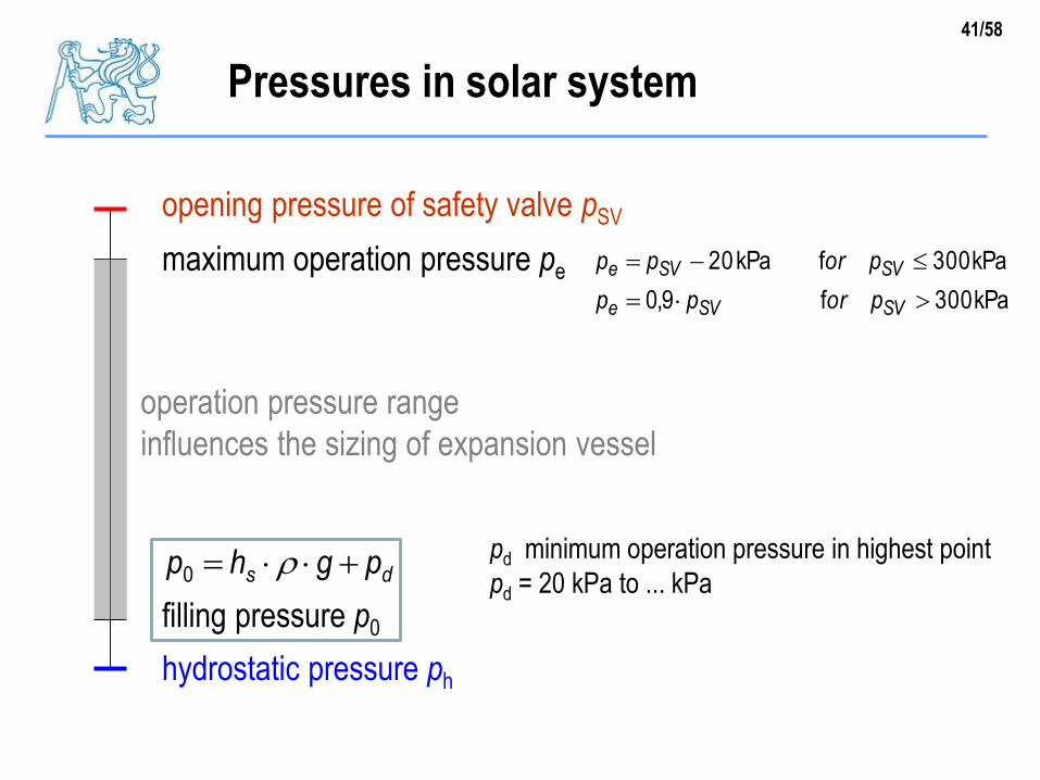
41/58
Pressures in solar system
opening pressure of safety valve pSV
maximum operation pressure pe
kPa300f9,0
kPa300fkPa20
SVSVe
SVSVe
porpp
porpp
hydrostatic pressure ph
filling pressure p0
ds pghp 0pd minimum operation pressure in highest point
pd = 20 kPa to ... kPa
operation pressure range
influences the sizing of expansion vessel

42/58
Safety (relief) valve
relief pressure
respects pressure
endurance of system
components
influences size of
expansion vessel
cap
spring ring
membrane
screw joint
sealing
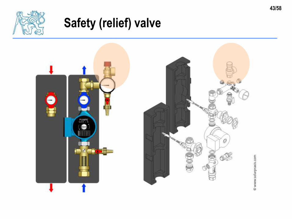
43/58
Safety (relief) valve

44/58
Location of safety valve
between safety valve and collector
must not be any valve
pressure loss at vapour mass flowrate
< 3 % of relief pressure
free outflow has to be assured from
relief
regular checks provided
no closure
kg/h][kWh/kg58.0
[kW]p
p
p
p
Q
r
Qm
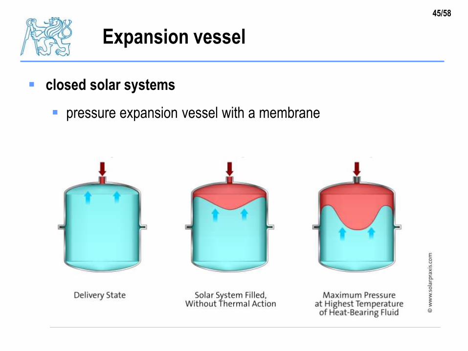
45/58
Expansion vessel
closed solar systems
pressure expansion vessel with a membrane
46/58
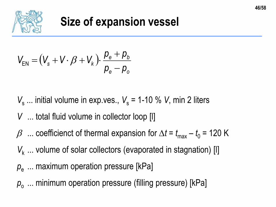
Size of expansion vessel
oe
beks
pp
ppVVVV
EN
Vs ... initial volume in exp.ves., Vs = 1-10 % V, min 2 liters
V ... total fluid volume in collector loop [l]
... coefficienct of thermal expansion for t = tmax – t0 = 120 K
Vk ... volume of solar collectors (evaporated in stagnation) [l]
pe ... maximum operation pressure [kPa]
po ... minimum operation pressure (filling pressure) [kPa]

47/58
Coefficient of thermal expansion
1)(
)(
)(
)()(
max
0
0
0max
t
t
tv
tvtv

48/58
Expansion vessel
selection of expansion vessel from a manufacturer predefined
sizes

49/58
Expansion vessel - location
right wrong

50/58
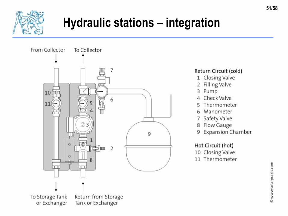
Hydraulic stations – integration
ciruclation pump
closing valves
check valve
connection of expansion vessel
safety valve
thermometers
51/58
Hydraulic stations – integration

52/58
Air venting
53/58
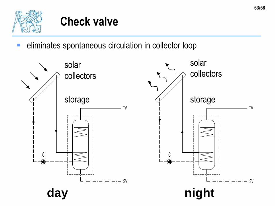
Check valve
eliminates spontaneous circulation in collector loop
solar
collectors
solar
collectors
storage storage
day night

54/58
Check valve
spring
spring
55/58
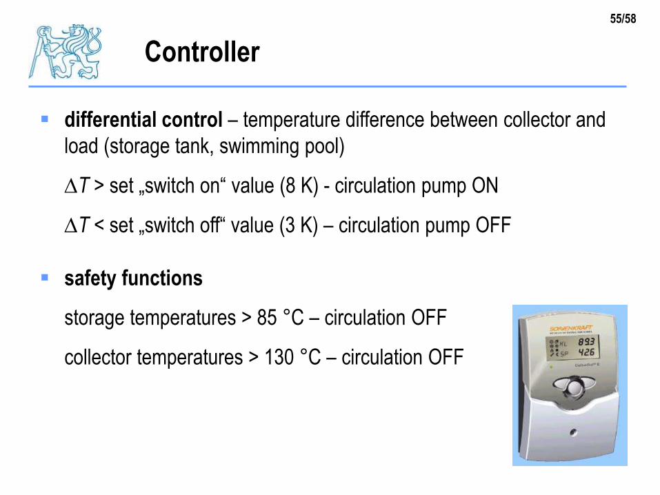
Controller
differential control – temperature difference between collector and
load (storage tank, swimming pool)
T > set „switch on“ value (8 K) - circulation pump ON
T < set „switch off“ value (3 K) – circulation pump OFF
safety functions
storage temperatures > 85 °C – circulation OFF
collector temperatures > 130 °C – circulation OFF
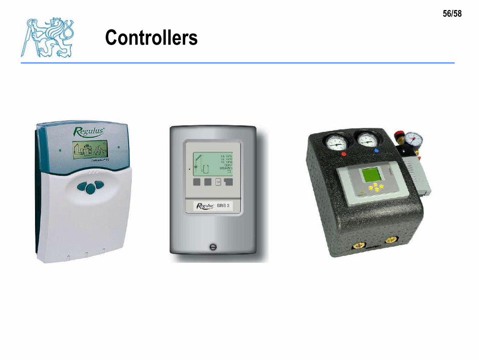
56/58
Controllers
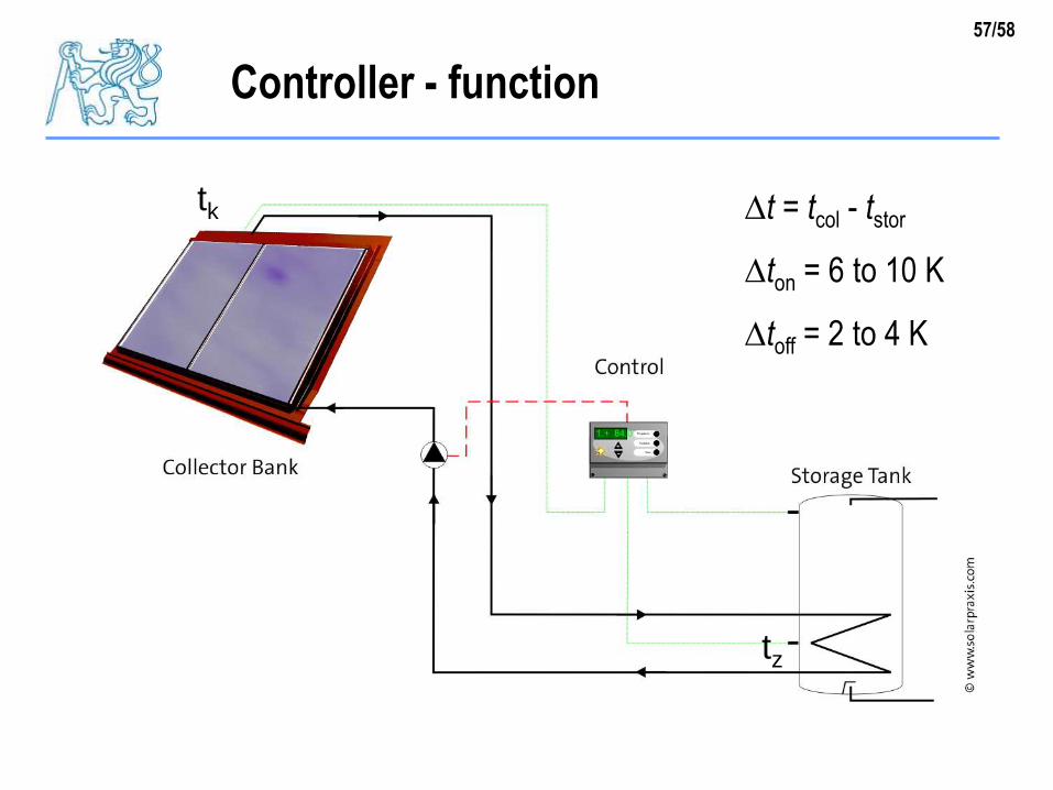
57/58
Controller - function
tz
tk t = tcol - tstor
ton = 6 to 10 K
toff = 2 to 4 K
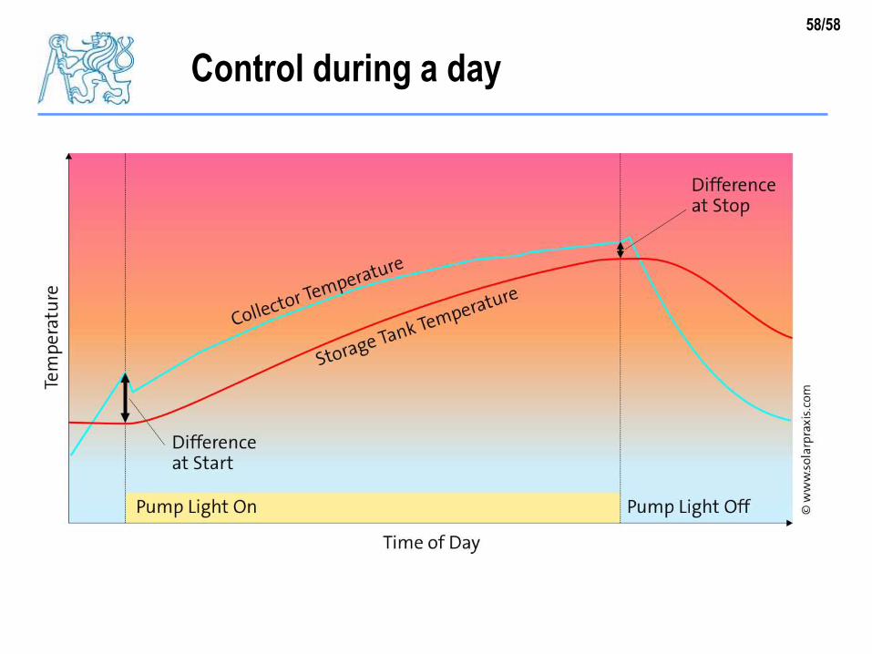
58/58
Control during a day
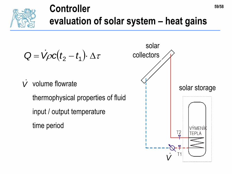
59/58Controller
evaluation of solar system – heat gains
12 ttcVQ solar
collectors
solar storage
V
volume flowrate
thermophysical properties of fluid
input / output temperature
time period
V