Embed Size (px)
Citation preview
17236733/B-10011-5
OPERATION MANUAL
LSCSubmersible Residue Dewatering Pump
LSPSelf-Priming Residue Dewatering Pump
TSURUMI MANUFACTURING CO., LTD.
INTRODUCTION
Thank you for selecting the Tsurumi LSC Submersible Residue Dewatering Pump and LSP Self-Priming Residue Dewatering Pump for your application.
This equipment should not be used for applications other than those listed in this manual. Failure to observe this precaution may lead to a malfunction or an accident. In the event of a malfunction or an accident, the manufacturer will not assume any liability. After reading this Operation Manual, keep it in a location that is easily accessible, so that it can be re-ferred to whenever information is needed while operating the equipment.
CONTENTS1. BE SURE TO READ FOR YOUR SAFETY ..................... 12. PART NAMES ................................................................. 43. PRIOR TO OPERATION ............................................... 54. INSTALLATION ............................................................. 65. ELECTRICAL WIRING .................................................... 86. OPERATION .................................................................... 107. MAINTENANCE AND INSPECTION ............................... 118. DISASSEMBLY AND REASSEMBLY PROCEDURE ...... 129. TROUBLESHOOTING .................................................. 15
-1-
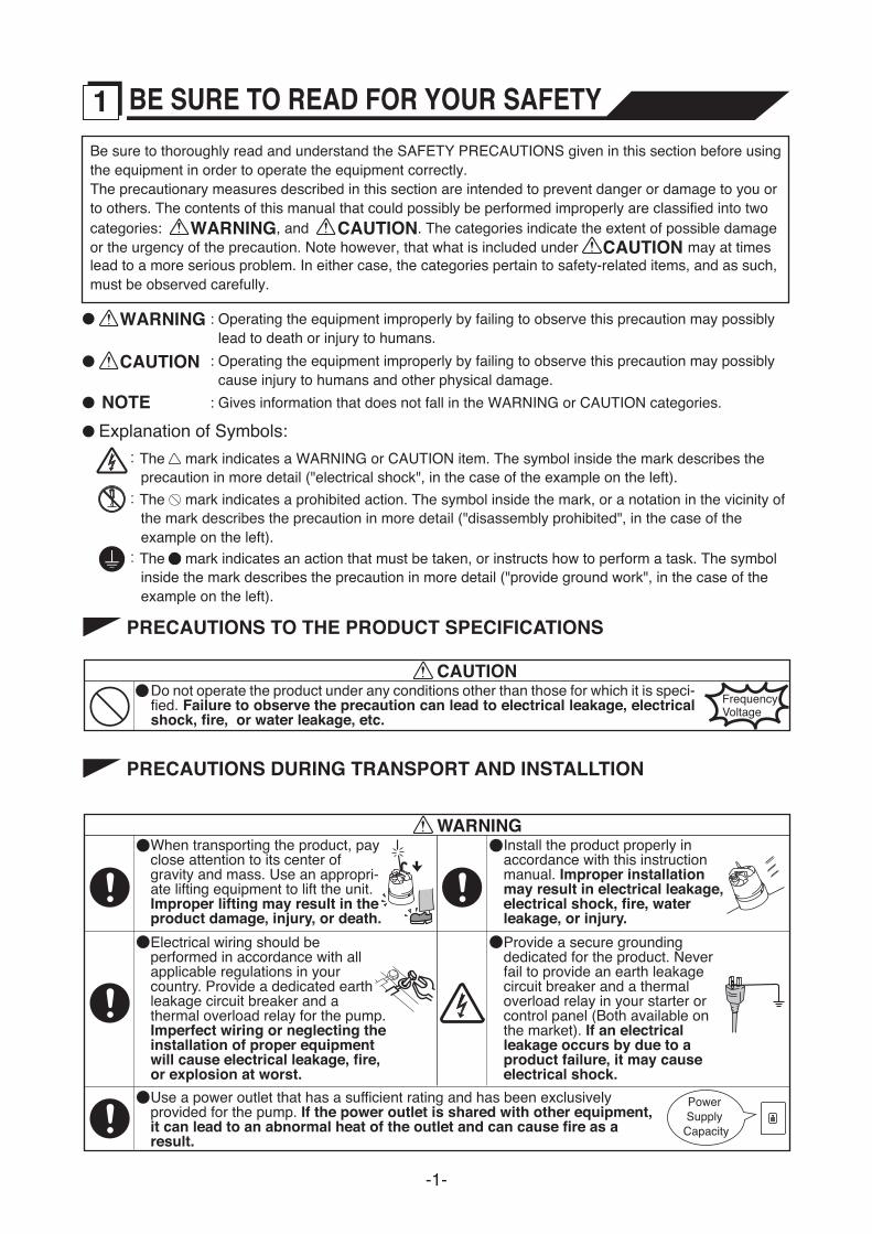
:The mark indicates an action that must be taken, or instructs how to perform a task. The symbol inside the mark describes the precaution in more detail ("provide ground work", in the case of the example on the left).
:The mark indicates a WARNING or CAUTION item. The symbol inside the mark describes the precaution in more detail ("electrical shock", in the case of the example on the left).
: Operating the equipment improperly by failing to observe this precaution may possibly cause injury to humans and other physical damage.
: Operating the equipment improperly by failing to observe this precaution may possibly lead to death or injury to humans.
: Gives information that does not fall in the WARNING or CAUTION categories.
:The mark indicates a prohibited action. The symbol inside the mark, or a notation in the vicinity of the mark describes the precaution in more detail ("disassembly prohibited", in the case of the example on the left).
Be sure to thoroughly read and understand the SAFETY PRECAUTIONS given in this section before using the equipment in order to operate the equipment correctly.The precautionary measures described in this section are intended to prevent danger or damage to you or to others. The contents of this manual that could possibly be performed improperly are classified into two categories: WARNING, and CAUTION. The categories indicate the extent of possible damage or the urgency of the precaution. Note however, that what is included under CAUTION may at times lead to a more serious problem. In either case, the categories pertain to safety-related items, and as such, must be observed carefully.
WARNING
CAUTION
NOTEExplanation of Symbols:
1 BE SURE TO READ FOR YOUR SAFETY
Do not operate the product under any conditions other than those for which it is speci-fied. Failure to observe the precaution can lead to electrical leakage, electrical shock, fire, or water leakage, etc.
CAUTIONFrequencyVoltage
PRECAUTIONS TO THE PRODUCT SPECIFICATIONS
WARNING
Power Supply Capacity
When transporting the product, pay close attention to its center of gravity and mass. Use an appropri-ate lifting equipment to lift the unit. Improper lifting may result in the product damage, injury, or death.Electrical wiring should be performed in accordance with all applicable regulations in your country. Provide a dedicated earth leakage circuit breaker and a thermal overload relay for the pump. Imperfect wiring or neglecting the installation of proper equipment will cause electrical leakage, fire, or explosion at worst.Use a power outlet that has a sufficient rating and has been exclusively provided for the pump. If the power outlet is shared with other equipment, it can lead to an abnormal heat of the outlet and can cause fire as a result.
Install the product properly in accordance with this instruction manual. Improper installation may result in electrical leakage, electrical shock, fire, water leakage, or injury.Provide a secure grounding dedicated for the product. Never fail to provide an earth leakage circuit breaker and a thermal overload relay in your starter or control panel (Both available on the market). If an electrical leakage occurs by due to a product failure, it may cause electrical shock.
PRECAUTIONS DURING TRANSPORT AND INSTALLTION
-2-
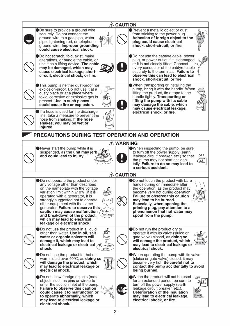
CAUTION
Do not scratch, fold, twist, make alterations, or bundle the cable, or use it as a lifting device. The cable may be damaged, which may cause electrical leakage, short-circuit, electrical shock, or fire.
Be sure to provide a ground wire securely. Do not connect the ground wire to a gas pipe, water pipe, lightening rod, or telephone ground wire. Improper grounding could cause electrical shock.
Do not use the cabtyre cable, power plug, or power outlet if it is damaged or it is not closely fitted. Connect every conductor of the cabtyre cable securely to the terminals. Failure to observe this can lead to electrical shock, short-circuit, or fire.When transporting or installing the pump, bring it with the handle. When lifting the product, tie a rope to the handle tightly. Transporting or lifting the pump with its cable may damage the cable, which may cause electrical leakage, electrical shock, or fire.
This pump is neither dust-proof nor explosion-proof. Do not use it at a dusty place or at a place where toxic, corrosive or explosive gas is present. Use in such places could cause fire or explosion.
Prevent a metallic object or dust from sticking to the power plug. Adhesion of foreign object to the plug could cause electrical shock, short-circuit, or fire.
If a hose is used for the discharge line, take a measure to prevent the hose from shaking. If the hose shakes, you may be wet or injured.
PRECAUTIONS DURING TEST OPERATION AND OPERATION
CAUTION
WARNINGNever start the pump while it is suspended, as the unit may jerk and could lead to injury.
When inspecting the pump, be sure to turn off the power supply (earth leakage circuit breaker, etc.) so that the pump may not start acciden-tally. Failure to do so may lead to a serious accident.
Do not operate the product under any voltage other than described on the nameplate with the voltage variation limit within ±10%. If it is operated with a generator, it is strongly suggested not to operate other equipment with the same generator. Failure to observe this caution may cause malfunction and breakdown of the product, which may lead to electrical leakage or electrical shock.
Do not touch the product with bare hands during or immediate after the operation, as the product may become very hot during operation. Failure to observe this caution may lead to be burned.Especially, when opening the priming plug, pay attention to a phenomenon that hot water may spout from the pump.
Do not use the product in a liquid other than water. Use in oil, salt water or organic solvents will damage it, which may lead to electrical leakage or electrical shock.
Do not run the product dry or operate it with its valve (sluice or gate valve) closed, as doing so will damage the product, which may lead to electrical leakage or electrical shock.When operating the pump with its valve (sluice or gate valve) closed, it may become very hot. Be careful not to contact the pump accidentally to avoid being burned.When the product will not be used for an extended period, be sure to turn off the power supply (earth leakage circuit breaker, etc.). Deterioration of the insulation may lead to electrical leakage, electrical shock, or fire.
For water only
RatedVoltage
OFF
Do not allow foreign objects (metal objects such as pins or wires) to enter the suction inlet of the pump. Failure to observe this caution could cause it to malfunction or to operate abnormally, which may lead to electrical leakage or electrical shock.
Do not use the product for hot or warm liquid over 40, as doing so will damage the product, which may lead to electrical leakage or electrical shock.
OFF
-3-
PRECAUTIONS DURING MAINTENANCE AND INSPECTION
CAUTION
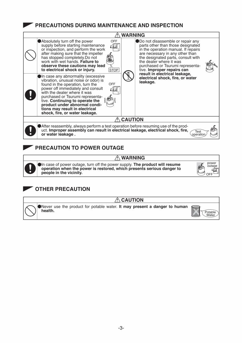
WARNINGAbsolutely turn off the power supply before starting maintenance or inspection, and perform the work after making sure that the impeller has stopped completely.Do not work with wet hands. Failure to observe these cautions may lead to electrical shock or injury.
After reassembly, always perform a test operation before resuming use of the prod-uct. Improper assembly can result in electrical leakage, electrical shock, fire, or water leakage .
In case any abnormality (excessive vibration, unusual noise or odor) is found in the operation, turn the power off immediately and consult with the dealer where it was purchased or Tsurumi representa-tive. Continuing to operate the product under abnormal condi-tions may result in electrical shock, fire, or water leakage.
Do not disassemble or repair any parts other than those designated in the operation manual. If repairs are necessary in any other than the designated parts, consult with the dealer where it was purchased or Tsurumi representa-tive. Improper repairs can result in electrical leakage, electrical shock, fire, or water leakage.
Test operation
STOP
OFF
OFF
PRECAUTION TO POWER OUTAGE
In case of power outage, turn off the power supply. The product will resume operation when the power is restored, which presents serious danger to people in the vicinity.
WARNINGpower outage
OFF
OTHER PRECAUTION
CAUTIONNever use the product for potable water. It may present a danger to human health. Potable
Water
-4-
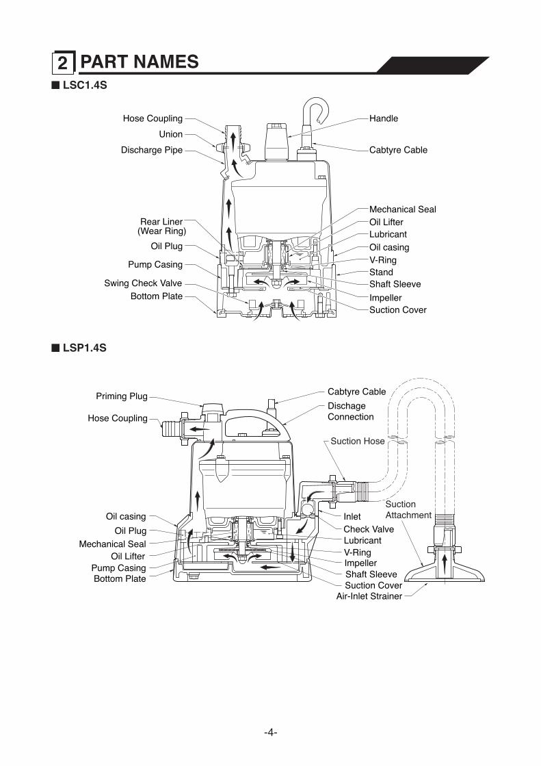
LSC1.4S
LSP1.4S
Hose Coupling
Oil Plug
Rear Liner
Pump Casing
Swing Check ValveBottom Plate
UnionDischarge Pipe
Handle
Mechanical SealOil LifterLubricantOil casingV-RingStandShaft SleeveImpellerSuction Cover
Cabtyre Cable
(Wear Ring)
Suction Hose
SuctionAttachment
Hose Coupling
Priming Plug
Oil Plug
Pump CasingBottom Plate
Dischage Connection
Mechanical SealOil Lifter
Lubricant
Oil casing
V-Ring
InletCheck Valve
Shaft SleeveImpeller
Suction CoverAir-Inlet Strainer
Cabtyre Cable
2 PART NAMES
-5-
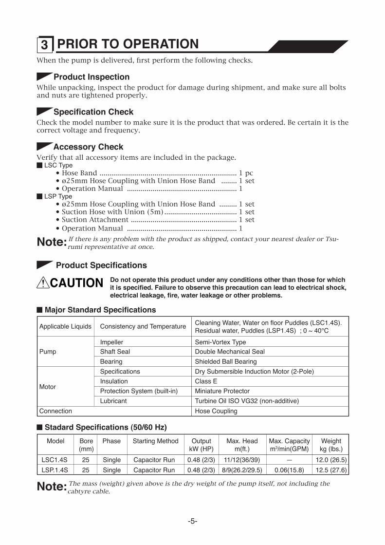
When the pump is delivered, first perform the following checks.
Product InspectionWhile unpacking, inspect the product for damage during shipment, and make sure all bolts and nuts are tightened properly.
Specification CheckCheck the model number to make sure it is the product that was ordered. Be certain it is the correct voltage and frequency.
Accessory CheckVerify that all accessory items are included in the package.
LSC Type • Hose Band ...................................................................... 1 pc • ø25mm Hose Coupling with Union Hose Band ........ 1 set • Operation Manual ........................................................ 1
LSP Type • ø25mm Hose Coupling with Union Hose Band ......... 1 set • Suction Hose with Union (5m) ..................................... 1 set • Suction Attachment ...................................................... 1 set • Operation Manual ........................................................ 1
Note: If there is any problem with the product as shipped, contact your nearest dealer or Tsu-rumi representative at once.
Major Standard Specifications
Applicable Liquids Consistency and Temperature Cleaning Water, Water on floor Puddles (LSC1.4S).Residual water, Puddles (LSP1.4S) ; 0 ~ 40°C
PumpImpeller Semi-Vortex TypeShaft Seal Double Mechanical Seal Bearing Shielded Ball BearingSpecifications Dry Submersible Induction Motor (2-Pole)Insulation Class E Protection System (built-in) Miniature Protector
Turbine Oil ISO VG32 (non-additive)LubricantConnection Hose Coupling
Motor
Stadard Specifications (50/60 Hz)
LSP.1.4SLSC1.4S
2525
SingleSingle
Capacitor RunCapacitor Run
Model Bore(mm)
0.48 (2/3)0.48 (2/3)
OutputkW (HP)
8/9(26.2/29.5)11/12(36/39)
Max. Headm(ft.)
0.06(15.8)—
Max. Capacitym3/min(GPM)
12.5 (27.6)12.0 (26.5)
Weightkg (lbs.)
Phase Starting Method
Note: The mass (weight) given above is the dry weight of the pump itself, not including the cabtyre cable.
3 PRIOR TO OPERATION
Product Specifications
CAUTION Do not operate this product under any conditions other than those for which it is specified. Failure to observe this precaution can lead to electrical shock, electrical leakage, fire, water leakage or other problems.
-6-
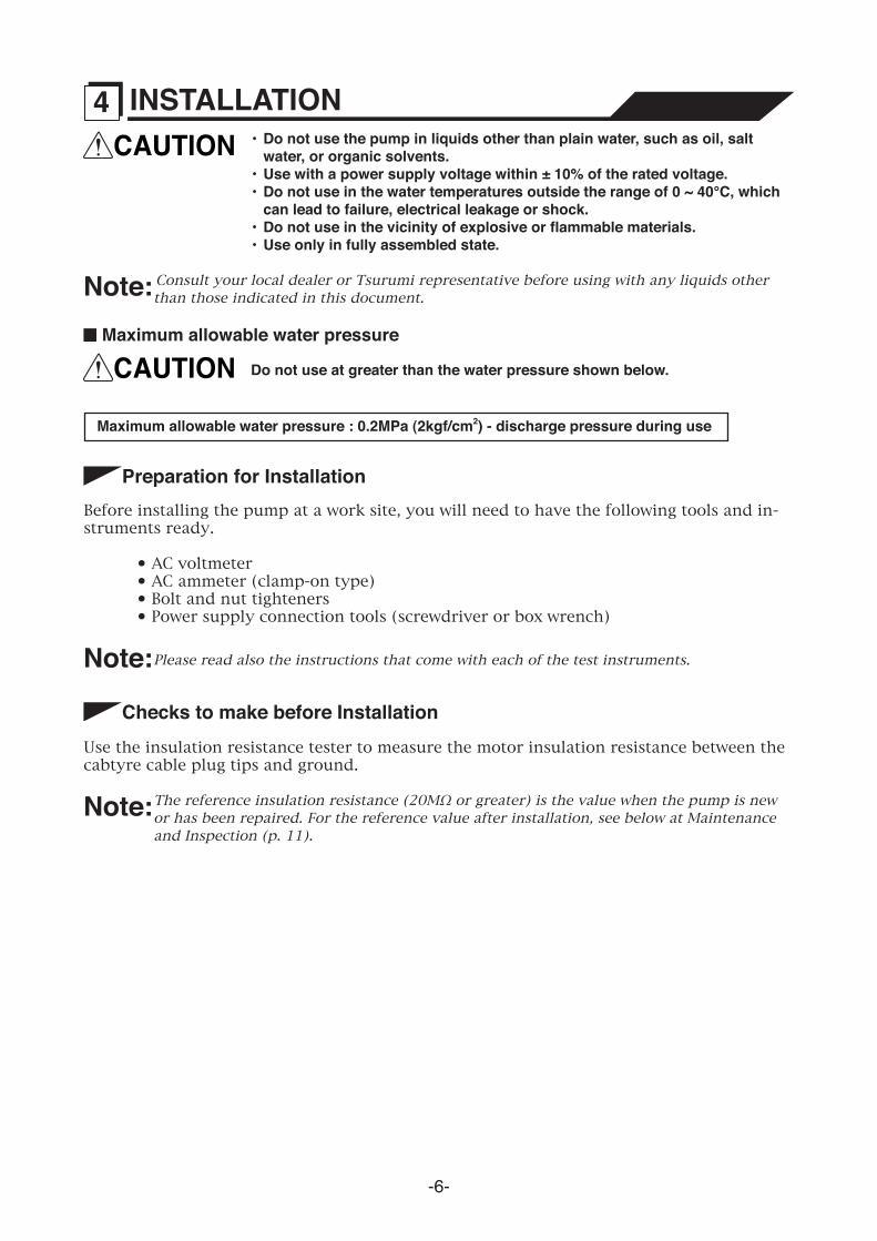
CAUTION • Do not use the pump in liquids other than plain water, such as oil, salt water, or organic solvents.
• Use with a power supply voltage within ± 10% of the rated voltage. • Do not use in the water temperatures outside the range of 0 ~ 40°C, which
can lead to failure, electrical leakage or shock. • Do not use in the vicinity of explosive or flammable materials. • Use only in fully assembled state.
Note: Consult your local dealer or Tsurumi representative before using with any liquids other than those indicated in this document.
Maximum allowable water pressure
CAUTION Do not use at greater than the water pressure shown below.
Maximum allowable water pressure : 0.2MPa (2kgf/cm2) - discharge pressure during use
4 INSTALLATION
Preparation for InstallationBefore installing the pump at a work site, you will need to have the following tools and in-struments ready.
• AC voltmeter • AC ammeter (clamp-on type) • Bolt and nut tighteners • Power supply connection tools (screwdriver or box wrench)
Note: Please read also the instructions that come with each of the test instruments.
Checks to make before InstallationUse the insulation resistance tester to measure the motor insulation resistance between the cabtyre cable plug tips and ground.
Note: The reference insulation resistance (20MΩ or greater) is the value when the pump is new or has been repaired. For the reference value after installation, see below at Maintenance and Inspection (p. 11).
-7-
Precautions in Installation
WARNING When installing the pump, pay close attention to its center of gravity and weight. If it is not lowered into place correctly, it may fall and be damaged or cause injury.
CAUTION Do not under any circumstances install or move the pump by suspending it from the cabtyre cable. The cable may be damaged, causing electrical leakage, shock, or fire.
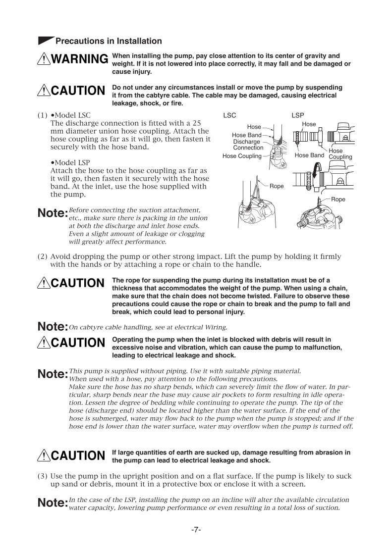
(1) •Model LSC The discharge connection is fitted with a 25
mm diameter union hose coupling. Attach the hose coupling as far as it will go, then fasten it securely with the hose band.
•Model LSP Attach the hose to the hose coupling as far as
it will go, then fasten it securely with the hose band. At the inlet, use the hose supplied with the pump.
Note: Before connecting the suction attachment, etc., make sure there is packing in the union at both the discharge and inlet hose ends. Even a slight amount of leakage or clogging will greatly affect performance.
Rope
HoseHose BandDischarge Connection
Rope
LSCHose
Hose CouplingHose Band
LSP
Hose Coupling
(2) Avoid dropping the pump or other strong impact. Lift the pump by holding it firmly with the hands or by attaching a rope or chain to the handle.
CAUTION The rope for suspending the pump during its installation must be of a thickness that accommodates the weight of the pump. When using a chain, make sure that the chain does not become twisted. Failure to observe these precautions could cause the rope or chain to break and the pump to fall and break, which could lead to personal injury.
Note: On cabtyre cable handling, see at electrical Wiring.
CAUTION Operating the pump when the inlet is blocked with debris will result in excessive noise and vibration, which can cause the pump to malfunction, leading to electrical leakage and shock.
Note: This pump is supplied without piping. Use it with suitable piping material. When used with a hose, pay attention to the following precautions. Make sure the hose has no sharp bends, which can severely limit the flow of water. In par-
ticular, sharp bends near the base may cause air pockets to form resulting in idle opera-tion. Lessen the degree of bedding while continuing to operate the pump. The tip of the hose (discharge end) should be located higher than the water surface. If the end of the hose is submerged, water may flow back to the pump when the pump is stopped; and if the hose end is lower than the water surface, water may overflow when the pump is turned off.
CAUTION If large quantities of earth are sucked up, damage resulting from abrasion in the pump can lead to electrical leakage and shock.
(3) Use the pump in the upright position and on a flat surface. If the pump is likely to suck up sand or debris, mount it in a protective box or enclose it with a screen.
Note: In the case of the LSP, installing the pump on an incline will alter the available circulation water capacity, lowering pump performance or even resulting in a total loss of suction.
-8-
Performing electrical wiringWARNING • Electrical wiring should be performed by a qualified person in accord with
all applicable regulations. Failure to observe this precaution not only risks breaking the law but is extremely dangerous.
• Incorrect wiring can lead to electrical leakage, electrical shock or fire. • Absolutely provide a dedicated earth leakage circuit breaker and a thermal
overload relay suitable for the pump (available on the market). Failure to follow this warning can cause electrical shock or explosion when the product fails or an electrical leakage occurs.
Provide an extra allowance in the capacity of power supply and wiring.
Grounding
WARNING Do not use the pump without first grounding it properly. Failure to ground it can lead to electrical shock from an electrical leak or pump malfunction.
CAUTION Do not attach the grounding wire to a gas pipe, water pipe, lightning arrestor or telephone grounding wire. Improper grounding can result in electrical shock.
Connecting the power supply
WARNING Before connecting leads to the terminal strip, make certain the power supply is turned off (circuit breaker, etc.), to avoid electrical shock, shorting, or unexpected starting of the pump, leading to injury.
WARNING Before inserting the power supply plug, make certain the power supply is turned off (circuit breaker, etc.), to avoid electrical shock, shorting, or unexpected starting of the pump, leading to injury.
CAUTION Do not use the product with the cabtyre cables or plug connected loosely, which can result in electric shock, shorting, or fire.
CAUTION Draw power from a dedicated power outlet having sufficient capacity for the pump. Sharing the outlet with other equipment may cause overheating at the branch outlet and could result in fire.
CAUTION Be sure to use a dedicated power supply with a ground leakage circuit breaker.
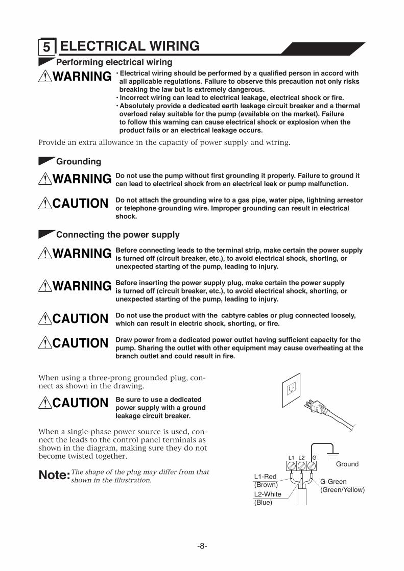
Note: The shape of the plug may differ from that shown in the illustration.
When using a three-prong grounded plug, con-nect as shown in the drawing.
When a single-phase power source is used, con-nect the leads to the control panel terminals as shown in the diagram, making sure they do not become twisted together.
5 ELECTRICAL WIRING
L1-Red(Brown) G-Green
(Green/Yellow)L2-White(Blue)
L1 L2 GGround
-9-
Electrical Circuit Diagrams
Cabtyre cable
CAUTION • If it is necessary to extend the cabtyre cable, use a core size equal to or larger than the original. This is necessary not only for avoiding a performance drop, but to prevent cable overheating which can result in fire, electrical leakage or electrical shock.
• If a cable with cut insulation or other damage is submerged in the water, there is danger of water seeping into the motor causing a short. This may result in damage to the pump, electrical leakage, electrical shock, or fire.
• Be careful not to let the cabtyre cable be cut or become twisted. This may result in damage to the pump, electrical leakage, electrical shock, or fire.
• If it is necessary to submerse the connection leads of the cabtyre cable in water, first seal the leads completely in a molded protective sleeve, to prevent electrical leakage, electrical shock, or fire.
Do not allow the cabtyre cable leads or power supply plug to become wet.Make sure the cable does not become excessively bent or twisted, and does not rub against a structure in a way that might damage it.
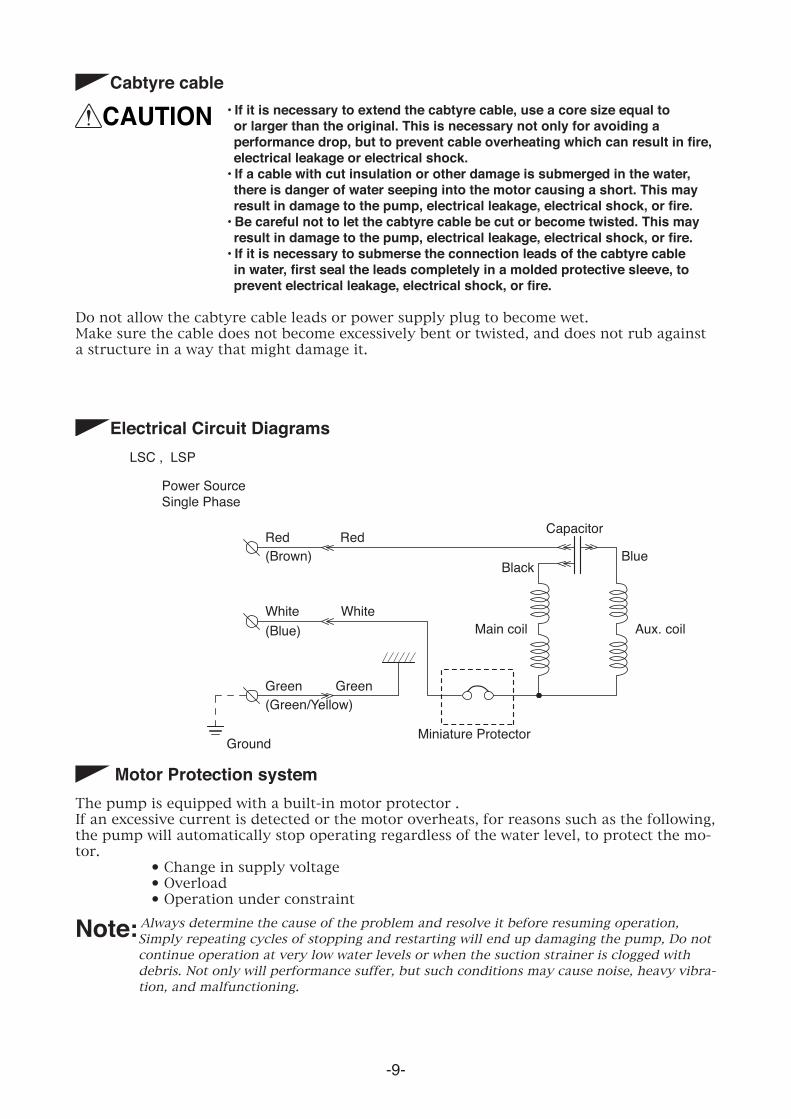
Power SourceSingle Phase
LSC , LSP
Red(Brown)
(Blue)
(Green/Yellow)
White
Green Green
White
RedBlue
GroundMiniature Protector
Black
Main coil Aux. coil
Capacitor
Motor Protection systemThe pump is equipped with a built-in motor protector .If an excessive current is detected or the motor overheats, for reasons such as the following, the pump will automatically stop operating regardless of the water level, to protect the mo-tor.
• Change in supply voltage• Overload • Operation under constraint
Note: Always determine the cause of the problem and resolve it before resuming operation, Simply repeating cycles of stopping and restarting will end up damaging the pump, Do not continue operation at very low water levels or when the suction strainer is clogged with debris. Not only will performance suffer, but such conditions may cause noise, heavy vibra-tion, and malfunctioning.
-10-
Before starting(1) Make sure once again that the product is of the correct voltage and frequency rating.
CAUTION Using the product at other than rated voltage and frequency will not only lower its performance but may damage the product.
Note:Confirm the rated voltage and frequency on the model name plate.
(2) Confirm the wiring, supply voltage, circuit breaker capacity, and motor insulation resis-tance.
Reference insulation resistance = 20MΩ or greater.
Note: The reference insulation resistance (20MΩ or greater) is the value when the pump is new or has been repaired. For the reference value after installation, see below at Maintenance and Inspection (p.11).
(3) The setting on the circuit breaker or other overload protector should be made in ac-cord with the rated current of the pump.
Note:See the model name plate on the pump for its rated current.
(4) When powering the pump with a generator, do not share the generator with other equipment.
Test Operation
WARNING Never Operate the pump while it is suspended in the air. The recoil may result in injury or other major accident.
Never start the pump when people are standing next to it. An electrical leak can result in electrical shock.
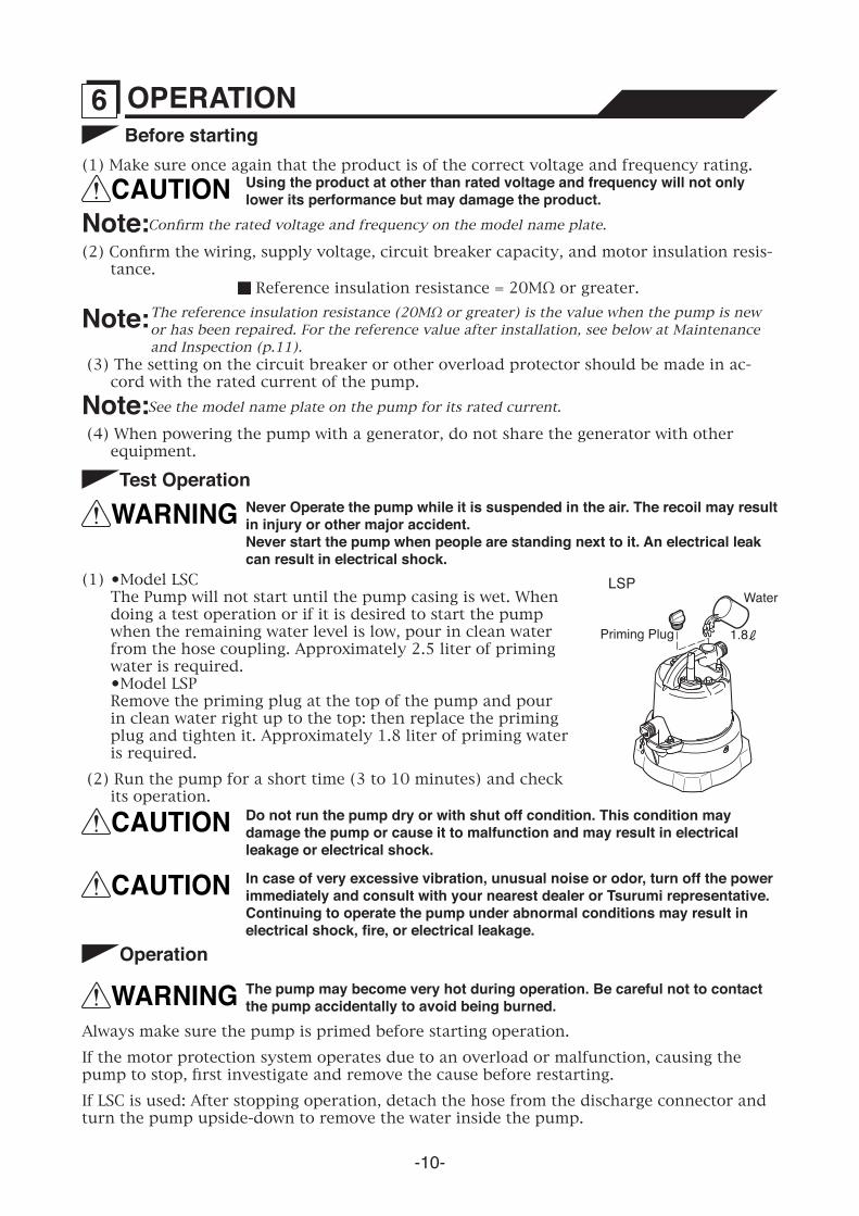
(1) •Model LSC The Pump will not start until the pump casing is wet. When
doing a test operation or if it is desired to start the pump when the remaining water level is low, pour in clean water from the hose coupling. Approximately 2.5 liter of priming water is required.
•Model LSP Remove the priming plug at the top of the pump and pour
in clean water right up to the top: then replace the priming plug and tighten it. Approximately 1.8 liter of priming water is required.
(2) Run the pump for a short time (3 to 10 minutes) and check its operation.
1.8
Water
Priming Plug
LSP
CAUTION In case of very excessive vibration, unusual noise or odor, turn off the power immediately and consult with your nearest dealer or Tsurumi representative. Continuing to operate the pump under abnormal conditions may result in electrical shock, fire, or electrical leakage.
Operation
WARNING The pump may become very hot during operation. Be careful not to contact the pump accidentally to avoid being burned.
Always make sure the pump is primed before starting operation.If the motor protection system operates due to an overload or malfunction, causing the pump to stop, first investigate and remove the cause before restarting.If LSC is used: After stopping operation, detach the hose from the discharge connector and turn the pump upside-down to remove the water inside the pump.
6 OPERATION
CAUTION Do not run the pump dry or with shut off condition. This condition may damage the pump or cause it to malfunction and may result in electrical leakage or electrical shock.
-11-
Regular maintenance and inspections are a necessity for continued efficient functioning of the pump. If any abnormal conditions are noticed, refer to the section on troubleshoot-ing (P.15) and take corrective measures immediately. It is recommended that a spare pump be kept ready in case of any problems.
Prior to Inspecting
WARNING Detach the cabtyre cable from the receptacle or terminals, after making certain the power supply (circuit breaker, etc.) is turned off. Failure to follow this precaution may result in a serious accident from electrical shock or unexpected starting of the pump motor.
(1) Washing the Pump Remove accumulated matter from the surface of the pump and wash it with clean water.
Take special care to remove any debris from the impeller.
(2) Inspecting the Pump Exterior Look for any peeling or chipped paint, and make sure the nuts and bolts are fastened
tightly. Any cracks in the surface should be repaired by cleaning that area, drying it and then applying a touchup coating.
Note: Touchup is not supplied. Note that some kinds of damage or looseness may require that the unit be disassembled for repairs. Please consult with your nearest dealer or Tsurumi representative.
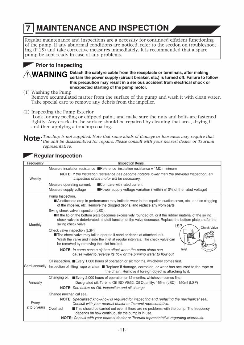
Regular InspectionFrequency
Monthly
Annually
Semi-annually
Weekly
Inspection Items
Every 2 to 5 years
Measure insulation resistance
Measure operating current.
NOTE: If the insulation resistance has become notable lower than the previous inspection, an inspection of the motor will be necessary.
Pump Inspection.
NOTE: In some case a siphon effect when the pump stops can cause water to reverse its flow or the priming water to flow out.
NOTE: See below on OIL inspection and oil change.
Changing oil.
NOTE: Specialized know-how is required for inspecting and replacing the mechanical seal. Consult with your nearest dealer or Tsurumi representative.
Overhaul
NOTE: Consult with your nearest dealer or Tsurumi representative regarding overhauls.
Swing check valve inspection (LSC).
Check valve inspection (LSP).
Change mechanical seal.
Measure supply voltage
Inlet
Check ValveLSP
Reference insulation resistance = 1MΩ minimum
Oil inspection. Every 1,000 hours of operation or six months, whichever comes first.
Every 2,000 hours of operation or 12 months, whichever comes first.Designated oil: Turbine Oil ISO VG32. Oil Quantity: 155ml (LSC) ; 150ml (LSP)
Compare with rated currentPower supply voltage variation ( within ±10% of the rated voltage)
A noticeable drop in performance may indicate wear in the impeller, suction cover, etc., or else clogging of the impeller, etc. Remove the clogged debris, and replace any worn parts.
If the lip on the bottom plate becomes excessively rounded off, or it the rubber material of the swing check valve is deteriorated, shutoff function of the valve decrease. Replace the bottom plate and/or the swing check valve.
The check valve may fail to operate if sand or debris at attached to it. Wash the valve and inside the inlet at regular intervals. The check valve canbe removed by removing the inlet hex.bolt.
This should be carried out even if there are no problems with the pump. The frequency depends on how continuously the pump is in use.
Inspection of lifting rope or chain Replace if damage, corrosion, or wear has occurred to the rope or the chain. Remove if foreign object is attaching to it.
7 MAINTENANCE AND INSPECTION
-12-
StorageWhen the pump is out of use for an extended period, wash it and dry it thoroughly, then store it indoors.
Note: Always run a test operation before putting the pump back into service.
Oil Inspection and Oil change
Note: Worn oil and other waste products should be disposed of by a qualified agent, in accord with applicable laws. The oil plug packing should be replaced each time the oil is inspected or changed.
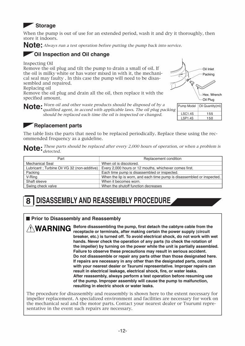
Inspecting OilRemove the oil plug and tilt the pump to drain a small of oil. If the oil is milky white or has water mixed in with it, the mechani-cal seal may faulty . In this case the pump will need to be disas-sembled and repaired.Replacing oilRemove the oil plug and drain all the oil, then replace it with the specified amount.
Hex. WrenchOil Plug
PackingOil Inlet
LSC1.4S 155
Pump Model Oil Quantity(ml)
LSP1.4S 150
Replacement partsThe table lists the parts that need to be replaced periodically. Replace these using the rec-ommended frequency as a guideline.
Note: These parts should be replaced after every 2,000 hours of operation, or when a problem is detected.
Mechanical SealPart Replacement condition
Lubricant ; Turbine Oil VG 32 (non-additive)PackingV-RingShaft sleeve
When oil is discolored.Every 2,000 hours or 12 mouths, whichever comes first.Each time pump is disassembled or inspected.When the lip is worn, and each time pump is disassembled or inspected.When it becomes worn.
Swing check valve When the shutoff function decreases
Prior to Disassembly and Reassembly
WARNING Before disassembling the pump, first detach the cabtyre cable from the receptacle or terminals, after making certain the power supply (circuit breaker, etc.) is turned off. To avoid electrical shock, do not work with wet hands. Never check the operation of any parts (to check the rotation of the impeller) by turning on the power while the unit is partially assembled. Failure to observe these precautions may result in serious accident.
Do not disassemble or repair any parts other than those designated here. If repairs are necessary in any other than the designated parts, consult with your nearest dealer or Tsurumi representative. Improper repairs can result in electrical leakage, electrical shock, fire, or water leaks.
After reassembly, always perform a test operation before resuming use of the pump. Improper assembly will cause the pump to malfunction, resulting in electric shock or water leaks.
The procedure for disassembly and reassembly is shown here to the extent necessary for impeller replacement. A specialized environment and facilities are necessary for work on the mechanical seal and the motor parts. Contact your nearest dealer or Tsurumi repre-sentative in the event such repairs are necessary.
8 DISASSEMBLY AND REASSEMBLY PROCEDURE
-13-
Oil Plug
Rear Liner (Wear Ring)
Pump Casing
Swing Check Valve
Bottom Plate
Oil casing
Packing
V-RingO-Ring
Stand
Shaft Sleeve
Impeller
Suction Cover
Plain Washer
Plain WasherSpring WasherHex. Cap Nut
Hex. Nut
Hex. BoltPlain Washer
Hex Bolt with Flat Washer
Reassembly Procedure
Observe the precautions given below and reassemble the unit in the reverse order of disas-sembly.
Note: The packings must be replaced with a new part. If any part is worn or damaged, make sure to replace it with a new part.
Remove sand or debris from rubber parts (rear liner, impeller, pump casing, and suction cover) before reassembling them. After installing the impeller and the suction cover, make sure that the impeller rotates smoothly and that it does not interfere with the suction cover.
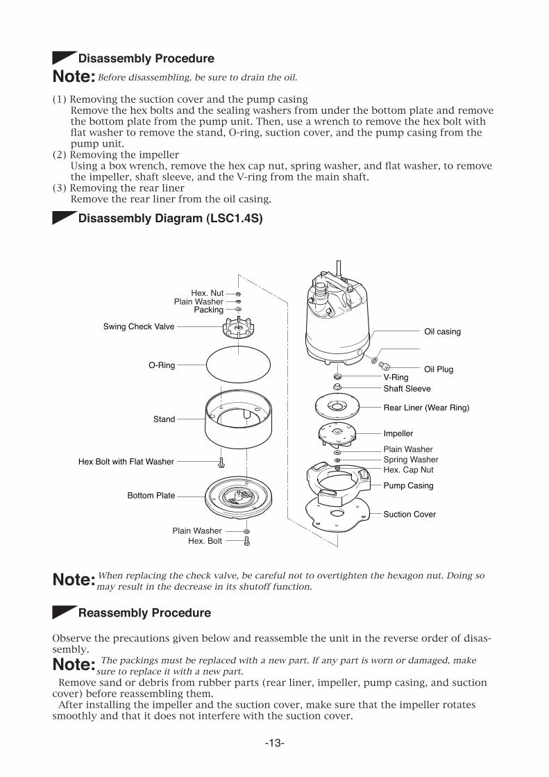
Disassembly Diagram (LSC1.4S)
Disassembly ProcedureNote: Before disassembling, be sure to drain the oil.
(1) Removing the suction cover and the pump casing Remove the hex bolts and the sealing washers from under the bottom plate and remove
the bottom plate from the pump unit. Then, use a wrench to remove the hex bolt with flat washer to remove the stand, O-ring, suction cover, and the pump casing from the pump unit.
(2) Removing the impeller Using a box wrench, remove the hex cap nut, spring washer, and flat washer, to remove
the impeller, shaft sleeve, and the V-ring from the main shaft.(3) Removing the rear liner Remove the rear liner from the oil casing.
Note: When replacing the check valve, be careful not to overtighten the hexagon nut. Doing so may result in the decrease in its shutoff function.
-14-
Reassembly
Exploded view(LSP1.4S)
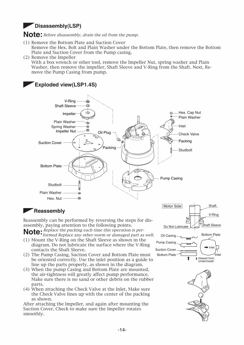
Disassembly(LSP)Note: Before disassembly, drain the oil from the pump.
(1) Remove the Bottom Plate and Suction Cover Remove the Hex. Bolt and Plain Washer under the Bottom Plate, then remove the Bottom
Plate and Suction Cover from the Pump casing. (2) Remove the Impeller With a box wrench or other tool, remove the Impeller Nut, spring washer and Plain
Washer, then remove the impeller, Shaft Sleeve and V-Ring from the Shaft. Next, Re-move the Pump Casing from pump.
Oil Plug
Pump Casing
Bottom Plate
PackingPacking
V-RingShaft Sleeve
Impeller
Impeller Nut
Suction Cover
Plain WasherPlain Washer
Inlet
Check Valve
Spring Washer
Hex. Cap Nut
Hex. Nut
Studbolt
Studbolt
Plain Washer
Bottom Plate
Bottom Plate
Motor Side
Do Not Lubricate Shaft Sleeve
Shaft
V-Ring
Oil Casing
Pump Casing
Suction Cover
Viewed from Undermeath
Inlet
Inlet
Reassembly can be performed by reversing the steps for dis-assembly, paying attention to the following points.
Note: Replace the packing each time this operation is per-formed Replace any other worm or damaged part as well.
(1) Mount the V-Ring on the Shaft Sleeve as shown in the diagram. Do not lubricate the surface where the V-Ring contacts the Shaft Sleeve.
(2) The Pump Casing, Suction Cover and Bottom Plate must be oriented correctly. Use the inlet position as a guide to line up the parts properly, as shown in the diagram.
(3) When the pump Casing and Bottom Plate are mounted, the air-tightness will greatly affect pump performance. Make sure there is no sand or other debris on the rubber parts.
(4) When attaching the Check Valve at the Inlet, Make sure the Check Valve lines up with the center of the packing as shown.
After attaching the Impeller, and again after mounting the Suction Cover, Check to make sure the Impeller rotates smoothly.
-15-
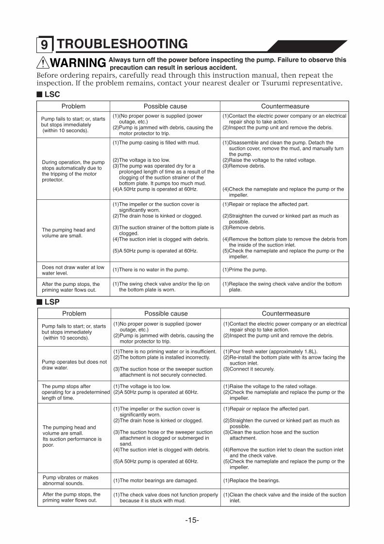
WARNING Always turn off the power before inspecting the pump. Failure to observe this precaution can result in serious accident.
Before ordering repairs, carefully read through this instruction manual, then repeat the inspection. If the problem remains, contact your nearest dealer or Tsurumi representative.
(1)Contact the electric power company or an electrical repair shop to take action.
(2)Inspect the pump unit and remove the debris.
(1)(No proper power is supplied (power outage, etc.)
(2)Pump is jammed with debris, causing the motor protector to trip.
(1)Disassemble and clean the pump. Detach the suction cover, remove the mud, and manually turn the pump.
(2)Raise the voltage to the rated voltage.(3)Remove debris.
(4)Check the nameplate and replace the pump or the impeller.
(1)The pump casing is filled with mud.
(2)The voltage is too low.(3)The pump was operated dry for a
prolonged length of time as a result of the clogging of the suction strainer of the bottom plate. It pumps too much mud.
(4)A 50Hz pump is operated at 60Hz.
(1)Prime the pump.(1)There is no water in the pump.
(1)Repair or replace the affected part.
(2)Straighten the curved or kinked part as much as possible.
(3)Remove debris.
(4)Remove the bottom plate to remove the debris from the inside of the suction inlet.
(5)Check the nameplate and replace the pump or the impeller.
(1)The impeller or the suction cover is significantly worn.
(2)The drain hose is kinked or clogged.
(3)The suction strainer of the bottom plate is clogged.
(4)The suction inlet is clogged with debris.
(5)A 50Hz pump is operated at 60Hz.
Pump fails to start; or, starts but stops immediately (within 10 seconds).
During operation, the pump stops automatically due to the tripping of the motor protector.
The pumping head and volume are small.
Does not draw water at low water level.
(1)Replace the swing check valve and/or the bottom plate.
(1)The swing check valve and/or the lip on the bottom plate is worn.
After the pump stops, the priming water flows out.
Problem Possible cause Countermeasure
LSC
(1)Contact the electric power company or an electrical repair shop to take action.
(2)Inspect the pump unit and remove the debris.
(1)No proper power is supplied (power outage, etc.)
(2)Pump is jammed with debris, causing the motor protector to trip.
(1)Raise the voltage to the rated voltage.(2)Check the nameplate and replace the pump or the
impeller.
(1)The voltage is too low.(2)A 50Hz pump is operated at 60Hz.
(1)Pour fresh water (approximately 1.8L).(2)Re-install the bottom plate with its arrow facing the
suction inlet.(3)Connect it securely.
(1)There is no priming water or is insufficient.(2)The bottom plate is installed incorrectly.
(3)The suction hose or the sweeper suction attachment is not securely connected.
(1)Replace the bearings.(1)The motor bearings are damaged.
(1)Repair or replace the affected part.
(2)Straighten the curved or kinked part as much as possible.
(3)Clean the suction hose and the suction attachment.
(4)Remove the suction inlet to clean the suction inlet and the check valve.
(5)Check the nameplate and replace the pump or the impeller.
(1)The impeller or the suction cover is significantly worn.
(2)The drain hose is kinked or clogged.
(3)The suction hose or the sweeper suction attachment is clogged or submerged in sand.
(4)The suction inlet is clogged with debris.
(5)A 50Hz pump is operated at 60Hz.
Pump fails to start; or, starts but stops immediately (within 10 seconds).
Pump operates but does not draw water.
The pump stops after operating for a predetermined length of time.
The pumping head and volume are small. Its suction performance is poor.
Pump vibrates or makes abnormal sounds.
(1)Clean the check valve and the inside of the suction inlet.
(1)The check valve does not function properly because it is stuck with mud.
After the pump stops, the priming water flows out.
Problem Possible cause Countermeasure
LSP
9 TROUBLESHOOTING

-16-
Disposal of ProductProperly dispose of the product by disassembling it, presorting the contents, and sending them to the waste material treatment site.
Remarks
Purchase date
Manufacturing number
Product model
The following information is required when ordering repairs or making other inquiries.