Embed Size (px)
Citation preview

SELECTION OF EQUIPMENT AND PROJECT ENGINEERING
FOR OPTIMIZING CIVIL AND STRUCTURAL COST
J. K. Singh, U. K. Mitra and Sunil Gupta
Holtec Consulting Private Limited, India
ABSTRACT
The cement plant capacities have come a long way leading to the present plant capacities. In recent
years, the quantum of civil and structural costs has grown disproportionately in respect to the
percentage of over all cost.
This necessitates the need of proper plant equipment selection and project engineering leading to
the savings in civil and structural cost and close coordination among various functional departments
to optimize the building size and shape.
1.0 SUMMARY
Based on HOLTEC’s in depth experience, it is possible and desirable to reduce civil and structural
costs in certain areas by adopting the cost effective solutions of project engineering. The areas
covered in this paper as case studies are:
a) Selection of proper design of reclaimers:
b) Location for raw mill/kiln chimney
c) Location of kiln feed bin
d) Locating the calibration point for weigh feeders in grinding systems
e) Construction technology for large capacity silos
f) New technology of receiving and unloading raw materials and solid fuels through trucks
g) Limestone crushing structure optimization
2.0 CASE STUDIES
Case studies have been carried out for above areas and the details have been provided below:
1. Selection of proper design of reclaimers
In general, the following two designs of side reclaimers are available:
a) Ascending trough design reclaimer, without retaining wall
b) Inclined reclaimer, with retaining wall
a. Ascending trough design reclaimer, without
retaining wall
b. Inclined reclaimer, with retaining wall
Fig-1 : Two designs of Side Reclaimers
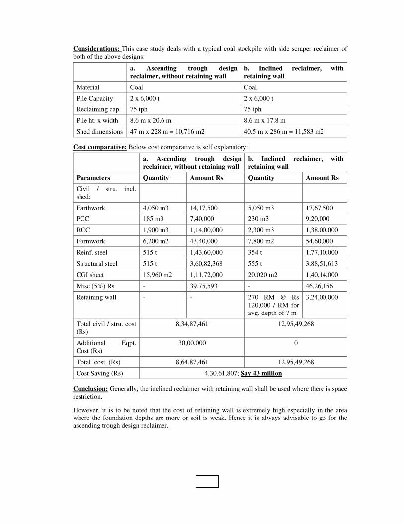
Considerations: This case study deals with a typical coal stockpile with side scraper reclaimer of
both of the above designs:
a. Ascending trough design
reclaimer, without retaining wall
b. Inclined reclaimer, with
retaining wall
Material Coal Coal
Pile Capacity 2 x 6,000 t 2 x 6,000 t
Reclaiming cap. 75 tph 75 tph
Pile ht. x width 8.6 m x 20.6 m 8.6 m x 17.8 m
Shed dimensions 47 m x 228 m = 10,716 m2 40.5 m x 286 m = 11,583 m2
Cost comparative: Below cost comparative is self explanatory:
a. Ascending trough design
reclaimer, without retaining wall
b. Inclined reclaimer, with
retaining wall
Parameters Quantity Amount Rs Quantity Amount Rs
Civil / stru. incl.
shed:
Earthwork 4,050 m3 14,17,500 5,050 m3 17,67,500
PCC 185 m3 7,40,000 230 m3 9,20,000
RCC 1,900 m3 1,14,00,000 2,300 m3 1,38,00,000
Formwork 6,200 m2 43,40,000 7,800 m2 54,60,000
Reinf. steel 515 t 1,43,60,000 354 t 1,77,10,000
Structural steel 515 t 3,60,82,368 555 t 3,88,51,613
CGI sheet 15,960 m2 1,11,72,000 20,020 m2 1,40,14,000
Misc (5%) Rs - 39,75,593 - 46,26,156
Retaining wall - - 270 RM @ Rs
120,000 / RM for
avg. depth of 7 m
3,24,00,000
Total civil / stru. cost
(Rs)
8,34,87,461 12,95,49,268
Additional Eqpt.
Cost (Rs)
30,00,000 0
Total cost (Rs) 8,64,87,461 12,95,49,268
Cost Saving (Rs) 4,30,61,807; Say 43 million
Conclusion: Generally, the inclined reclaimer with retaining wall shall be used where there is space
restriction.
However, it is to be noted that the cost of retaining wall is extremely high especially in the area
where the foundation depths are more or soil is weak. Hence it is always advisable to go for the
ascending trough design reclaimer.

2. Location for raw mill/kiln chimney
Chimney for raw mill / kiln bag house can be:
a. Steel chimney supported with preheater tower ; or
b. Standalone chimney:
i. Standalone (semi-guided) steel chimney ; or
ii. Standalone (self supported) concrete chimney with fire brick lining
a. Steel chimney supported
with preheater tower
b-i. Standalone (semi-
guided) steel chimney
b-ii. Standalone (self-
supported) concrete chimney
Fig-2 : Two locations of raw mill / kiln chimney
The chimney height is governed by preheater height, whether it is supported with preheater or it is
standalone one. This case study has been done on a typical chimney with either of the above
options.
Considerations: Chimney height : 165 m; Dia: 5.6 m, Foundation : RCC
Advantages and disadvantages of these options are:
S.
No.
a. Steel chimney supported
with preheater tower
b-i. Standalone (semi-
guided) steel chimney
b-ii. Standalone (self
supported) concrete
chimney
1. Lower cost, due to saving in
chimney shell, foundation and
supports cost
High cost
Substantially high cost
2. Construction period is
substantially low
Construction period is
high
Construction period is very
high
3. Easy accessibility to chimney
by PH lift / staircase
Separate access for
chimney is required
Separate access for
chimney is required
4. No fire brick lining and acid-
resistant required, acts as duct
Fire brick lining and acid
resistant not required
Fire brick lining and acid
resistant required
5. Bag house with same side
inlet and outlet, resulting in
marginal increase in cost
Bag house with inlet and
outlet on opposite side
Bag house with inlet and
outlet on opposite side

HOLTEC has done engineering for many plants worldwide, where main chimney has been
supported with preheater tower.
Cost comparative: Below cost comparative is self explanatory:
a. Steel chimney
supported with
preheater tower
b-i. Standalone (semi-
guided) steel chimney
b-ii. Standalone (self
supported) concrete
chimney
Parameters Quantity Amount Rs Quantity Amount Rs Quantity Amount Rs
Civil / stru.:
Earthwork 300 m3 1,05,500 1,750 m3 6,12,500 1,140 m3 3,99,000
PCC 6 m3 24,000 30 m3 1,20,000 25 m3 1,00,000
RCC 115 m3 6,90,000 1,800 m3 1,08,00,000 2,851 m3 1,71,00,000
Formwork 150 m2 1,05,000 6,750 m2 47,25,000 190 m2 1,33,000
Slipform 0 0 0 0 9,025 m2 67,68,750
Reinf. steel 20 t 9,77,000 360 t 18,00,000 570 t 2,85,00,000
Structural steel 500 t 35,00,000 500 t 35,00,000 115 t 80,50,000
Fire brick 0 0 0 0 1,425 t 1,71,00,000
Acid resistant 0 0 0 0 1,378 t 1,92,85,000
Painting Lumpsum 20,00,000 Lumpsum 20,00,000 Lumpsum 25,00,000
Misc (5%) Rs - 19,45,075 - 35,62,875 - 49,96,788
Total civil /
stru. cost (Rs)
4,08,46,575 7,48,20,375 10,49,32,538
Additional cost
of bag house
with same side
inlet, o/l (Rs)
60,00,000 0 0
Total cost (Rs) 4,68,46,575 7,48,20,375 10,49,32,538
Cost
Saving(Rs)
With Option a: 5,80,85,963; Say 58 million (over option b-ii)
With Option a: 2,79,73,800, Say 28 million (over option b-i)
Conclusion: It has been evolved that there shall be substantial saving in civil / structural cost and
construction time of chimney, if it is supported with preheater.
3. Location of kiln feed bin
Kiln feed bin can be located:
a. In the space available in preheater tower at first floor
b. Underneath blending silo

a. Kiln feed bin in preheater tower at first floor b. Kiln feed bin below blending silo
Fig-3 : Two locations of kiln Feed Bin
This case study deals with a typical kiln feed bin located in either of above locations.
Considerations: Raw meal silo : 15,000 t; Dia : 20 m; saving (with option b) in silo height and silo
feed bucket elevator height: 11 m; new bucket elevator requirement (21 m c-c) for kiln feed bin
feeding (with option a) and an additional bag filter required (with option a)
Advantages and disadvantages of these options are:
S.
No.
a. Kiln feed bin in preheater tower at first floor b. Kiln feed bin below blending
silo
1. Lower civil cost, due to considerable reduction in
silo height
Higher civil cost
2. Slightly higher mechanical equipment cost due to
additional bucket elevator and increase in air slides
length, part of which gets compensated by reduced
raw meal silo feed bucket elevator height
Slightly lower mechanical
equipment cost
3. Slightly increased specific power consumption, part
of which gets compensated by reduced raw meal
silo feed bucket elevator height
Slightly lower specific power
consumption
4. Fair amount of working space available around kiln
feed bin in better conditions
Available working space is less in
hot conditions
5. Construction period for silo is less Longer construction period for silo
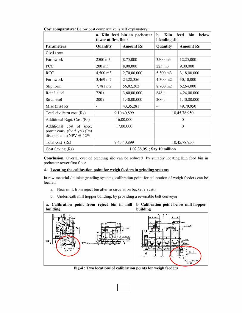
Cost comparative: Below cost comparative is self explanatory:
a. Kiln feed bin in preheater
tower at first floor
b. Kiln feed bin below
blending silo
Parameters Quantity Amount Rs Quantity Amount Rs
Civil / stru:
Earthwork 2500 m3 8,75,000 3500 m3 12,25,000
PCC 200 m3 8,00,000 225 m3 9,00,000
RCC 4,500 m3 2,70,00,000 5,300 m3 3,18,00,000
Formwork 3,469 m2 24,28,356 4,300 m2 30,10,000
Slip form 7,781 m2 56,02,262 8,700 m2 62,64,000
Reinf. steel 720 t 3,60,00,000 848 t 4,24,00,000
Stru. steel 200 t 1,40,00,000 200 t 1,40,00,000
Misc (5%) Rs - 43,35,281 - 49,79,950
Total civil/stru cost (Rs) 9,10,40,899 10,45,78,950
Additional Eqpt. Cost (Rs) 16,00,000 0
Additional cost of spec.
power cons. (for 5 yrs) (Rs)
discounted to NPV @ 12%
17,00,000 0
Total cost (Rs) 9,43,40,899 10,45,78,950
Cost Saving (Rs) 1,02,38,051; Say 10 million
Conclusion: Overall cost of blending silo can be reduced by suitably locating kiln feed bin in
preheater tower first floor
4. Locating the calibration point for weigh feeders in grinding systems
In raw material / clinker grinding systems, calibration point for calibration of weigh feeders can be
located:
a. Near mill, from reject bin after re-circulation bucket elevator
b. Underneath mill hopper building, by providing a reversible belt conveyor
a. Calibration point from reject bin in mill
building
b. Calibration point below mill hopper
building
Fig-4 : Two locations of calibration points for weigh feeders

By shifting the calibration point to reject bin after re-circulation bucket elevator, load bearing mill
hoppers building can be lowered down, resulting in reduced civil / structural cost. This will also
result in saving of one reversible belt conveyor incl. drive and motor below mill hoppers, de-
dusting of one transfer point and marginal saving in specific power consumption.
Considerations: Building size : 31 m x 9 m, Saving in building height (with option b) : 5 m, saving
of one reversible belt conveyor below mill hoppers, its drive and one bag filter
Cost comparative: Below cost comparative is self explanatory:
a. Calibration point from
reject bin in mill building
b. Calibration point below mill
hopper building
Parameters Quantity Amount Rs Quantity Amount Rs
Civil / stru:
Earthwork 1,300 m3 4,55,000 1,500 m3 5,25,000
PCC 20 m3 80,000 25 m3 1,00,000
RCC 1,750 m3 1,05,00,000 1,900 m3 1,14,00,000
Formwork 6,125 m2 42,87,500 6,650 m2 46,55,000
Reinf. steel 298 t 1,48,75,000 323 t 1,61,50,000
Stru. steel 100 t 70,00,000 135 t 94,15,000
Misc (5%) Rs - 18,59,875 - 21,12,250
Total civil / stru cost
(Rs)
3,90,57,375 4,43,57,250
Additional Eqpt. Cost(Rs) 0 10,00,000
Total cost (Rs) 3,90,57,375 4,53,57,250
Cost Saving (Rs) 62,99,875; Say 6.3 million
Conclusion: By providing calibration point from reject bin near mills, load bearing mill hoppers
building can be lowered down, resulting in reduced civil / structural cost as well as equipment cost
5. Construction technology for large capacity silos
Silos can be constructed as:
a. RCC silos, without pre-stressing i.e. conventional silos
b. Pre-stressed silos
This case study deals with cost comparison of typical clinker silos using either of above technology.

a. RCC silos, without pre-stressing b. Pre-stressed silos
Fig-5 : Two locations of raw mill / kiln chimney
Considerations: Clinker silo capacity : 50,000 t; dia : 40 m; height : 40 m
Advantages and disadvantages of these options are:
S. No. a. RCC silos, without pre-stressing b. Pre-stressed silos
1. Lower civil cost Higher civil cost
2. Ordinary skilled work force required Highly skilled execution team required
3. Construction time is lower Construction time is higher
Cost comparative: Below cost comparative is self explanatory:
a. Silos, without pre-stressing b. Pre-stressed silos
Parameters Quantity Amount Rs Quantity Amount Rs
Civil / stru:
Earthwork 12,000 m3 42,00,000 12,000 m3 42,00,000
PCC / plum 2,870 m3 1,10,67,500 2,870 m3 1,10,67,500
RCC 7,000 m3 4,20,00,000 7,000 m3 4,20,00,000
Formwork 2,625 m2 18,37,500 2,625 m2 18,37,500
Slip form 12,500 m2 90,00,000 12,500 m2 90,00,000
Reinf. steel 1,050 t 5,25,00,000 945 t 4,72,50,000
Structural steel 200 t 1,40,00,000 200 t 1,40,00,000
CGI sheet 2,000 m2 14,00,000 2,000 m2 14,00,000
Deck plate 28 t 19,60,000 28 t 19,60,000
RR masonry 5,800 m3 1,62,40,000 5,800 m3 1,62,40,000
Pre-stressing work 0 0 150 t 2,25,00,000
Misc (5%) Rs - 77,10,250 - 86,47,750
Total civil / stru. cost(Rs) 16,19,15,250 18,16,02,750
Cost Saving (Rs) 1,96,87,500, Say 19.7 million
Conclusion: Large capacity silos can also be constructed without pre-stressing, thus, reducing
structural cost and construction time, and eliminates necessity of highly skilled execution team
specially for pre-stressing.
HOLTEC has done engineering for many large capacity clinker silos without pre-stressing, for
e.g.:
♦ Binani Cement : 50,000 t, 40 m dia, year 2006-07
♦ Chettinad Cement : 55,000 t, 40 m dia, year 2006-07
♦ KJS Cement : 50,000 t, 40 m dia, year 2009-10
♦ Lafarge, Arasmeta : 40,000 t, 40 m dia, year 2005-06
♦ OCL Rajgangpur : 40,000 t, 40 m dia, year 2007-08
♦ Soufian Cement Company, Iran : 45,000 t, 40 m dia, year 2009
Some other silos without pre-stressing designed by HOLTEC, under execution are:
♦ Dungsum Cement Corporation Ltd., Bhutan, Clinker silo : 45,000 t, 40 m dia
♦ Wonder cement Ltd., Clinker silo : 40,000 t, 40 m dia
Some clinker silos with pre-stressing designed by HOLTEC are:
♦ Binani Cement : 40,000 t, 35.5 m dia, year 1995-96
♦ Chettinad Cement : 40,000 t, 35.5 m dia, year 1999-00
♦ Grasim Cement (Grasim South plant): 40,000 t, 35.5 m dia, year 1998-99
♦ Grasim Cement, Kotputli : 1,50,000 t, 65 m dia, year 2007-08
♦ National Cement Company, Yemen : 45,000 t, 35.5 m dia, year 2006-07
♦ Zuari Cement : 91,000 t, 60 m dia, year 2006-07
6. New technology of receiving and unloading raw materials and solid fuels through
trucks:
Bulk materials by trucks can be received by:
a. Truck tippler and Box type feeders
b. Truck tippler, underground hopper (in RCC and / or steel construction), followed by
apron feeder and belt conveyor
Conventional system used for receiving materials is underground dump hopper followed by apron
feeder and belt conveyor in tunnel. A box type feeder is a combination of an inclined apron-belt
with an in-built horizontal box for receiving materials. In conventional system, an additional belt
conveyor is also required to convey material out of tunnel, which results in an additional transfer
point and venting point. Both of above systems can be integrated with truck tipper, as per
requirement.
a. Box type feeder b. Underground hopper followed by apron
feeder
System comprises of :
♦ Truck tippler
♦ Box feeder
♦ Small ramp
System comprises of :
♦ Truck tippler
♦ Dump hopper (underground)
♦ Ramp
♦ Apron feeder
♦ An additional belt conveyor
♦ Tunnel
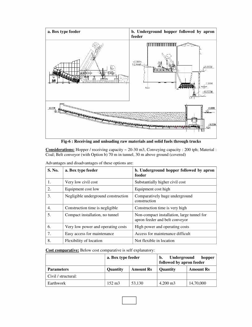
a. Box type feeder b. Underground hopper followed by apron
feeder
Fig-6 : Receiving and unloading raw materials and solid fuels through trucks
Considerations: Hopper / receiving capacity ~ 20-30 m3, Conveying capacity : 200 tph; Material :
Coal; Belt conveyor (with Option b) 70 m in tunnel, 30 m above ground (covered)
Advantages and disadvantages of these options are:
S. No. a. Box type feeder b. Underground hopper followed by apron
feeder
1. Very low civil cost Substantially higher civil cost
2. Equipment cost low Equipment cost high
3. Negligible underground construction Comparatively huge underground
construction
4. Construction time is negligible Construction time is very high
5. Compact installation, no tunnel Non-compact installation, large tunnel for
apron feeder and belt conveyor
6. Very low power and operating costs High power and operating costs
7. Easy access for maintenance Access for maintenance difficult
8. Flexibility of location Not flexible in location
Cost comparative: Below cost comparative is self explanatory:
a. Box type feeder b. Underground hopper
followed by apron feeder
Parameters Quantity Amount Rs Quantity Amount Rs
Civil / structural:
Earthwork 152 m3 53,130 4,200 m3 14,70,000

a. Box type feeder b. Underground hopper
followed by apron feeder
Parameters Quantity Amount Rs Quantity Amount Rs
PCC 10 m3 40,000 50 m3 2,00,000
RCC 35 m3 2,10,000 1,100 m3 66,00,000
Formwork 20 m2 14,000 3,900 m2 27,30,000
Reinf. steel 3.5 t 1,75,000 132 t 66,00,000
Structural steel 15 t 10,50,000 40 t 28,00,000
CGI sheet 0 0 650 m2 4,55,000
Belt conveyor (covered) 0 0 30 RM @ Rs
50,000 / RM
15,00,000
Ramp Lumpsum 400,000 Lumpsum 900,000
Misc (5%) Rs - 97,107 - 11,62,750
Total civil / stru. cost (Rs) 20,39,237 2,44,17,750
Eqpt. Cost (Rs) 90,00,000 97,00,000
Total cost (Rs) 1,10,39,237 3,41,17,750
Cost Saving (Rs) 2,30,78,513; Say 23 million
On an average, 3 systems are installed for receiving and unloading raw materials and solid fuels in a
typical cement plant. Thus, cost saving for a plant shall be 3 x Rs 23 million, i.e. Rs 69 million.
Conclusion: Box type feeders can be used in place of underground hoppers and feeders, totally
above ground reducing cost of ownership (equipment cost plus civil / structural cost) as well as
execution / installation time. Box type feeder is also highly favored in areas, where water table is
high.
7. Limestone crushing structure optimization
Optimization in limestone structure is possible with reduction in retaining wall length and volume.
This is effectively done by decreasing length of retaining wall and providing wing wall followed by
stone pitching / natural slope.
a. Structure with reduced retaining wall b. Structure with full retaining wall
Fig-7 : Limestone crushing structure optimization
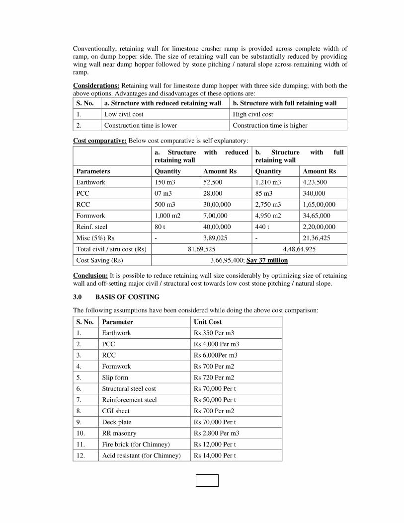
Conventionally, retaining wall for limestone crusher ramp is provided across complete width of
ramp, on dump hopper side. The size of retaining wall can be substantially reduced by providing
wing wall near dump hopper followed by stone pitching / natural slope across remaining width of
ramp.
Considerations: Retaining wall for limestone dump hopper with three side dumping; with both the
above options. Advantages and disadvantages of these options are:
S. No. a. Structure with reduced retaining wall b. Structure with full retaining wall
1. Low civil cost High civil cost
2. Construction time is lower Construction time is higher
Cost comparative: Below cost comparative is self explanatory:
a. Structure with reduced
retaining wall
b. Structure with full
retaining wall
Parameters Quantity Amount Rs Quantity Amount Rs
Earthwork 150 m3 52,500 1,210 m3 4,23,500
PCC 07 m3 28,000 85 m3 340,000
RCC 500 m3 30,00,000 2,750 m3 1,65,00,000
Formwork 1,000 m2 7,00,000 4,950 m2 34,65,000
Reinf. steel 80 t 40,00,000 440 t 2,20,00,000
Misc (5%) Rs - 3,89,025 - 21,36,425
Total civil / stru cost (Rs) 81,69,525 4,48,64,925
Cost Saving (Rs) 3,66,95,400; Say 37 million
Conclusion: It is possible to reduce retaining wall size considerably by optimizing size of retaining
wall and off-setting major civil / structural cost towards low cost stone pitching / natural slope.
3.0 BASIS OF COSTING
The following assumptions have been considered while doing the above cost comparison:
S. No. Parameter Unit Cost
1. Earthwork Rs 350 Per m3
2. PCC Rs 4,000 Per m3
3. RCC Rs 6,000Per m3
4. Formwork Rs 700 Per m2
5. Slip form Rs 720 Per m2
6. Structural steel cost Rs 70,000 Per t
7. Reinforcement steel Rs 50,000 Per t
8. CGI sheet Rs 700 Per m2
9. Deck plate Rs 70,000 Per t
10. RR masonry Rs 2,800 Per m3
11. Fire brick (for Chimney) Rs 12,000 Per t
12. Acid resistant (for Chimney) Rs 14,000 Per t
4.0 REFERENCES
The following reference projects have been refereed for the Case Studies:
1. Selection of proper design of reclaimers : 3,000 tpd Dungsum Cement Corporation Ltd.,
Bhutan
2. Location for raw mill/kiln chimney : Reliance Cement Company Pvt. Ltd., 10,000 tpd
Integrated Unit, Maihar, MP, India
3. Location of kiln feed bin : 3,000 tpd Dungsum Cement Corporation Ltd., Bhutan
4. Locating the calibration point for weigh feeders in grinding systems : 4,500 tpd Dalmia
Cement Ltd. – Kadappa, India
5. Construction technology for large capacity silos : As mentioned in case study above
6. New technology of receiving and unloading raw materials and solid fuels through trucks :
3,000 tpd Dungsum Cement Corporation Ltd., Bhutan
7. Limestone crushing structure optimization : 6,500 tpd Wonder Cement Ltd., Nimbahera,
Rajasthan, India
5.0 CONCLUSION AND RECOMMENDATIONS
Net saving with application of all of the above case studies shall be in the order of Rs 250 millions.
However, actual cost saving shall depend on case to case basis for each project, concept, capacity
etc.