Embed Size (px)
Citation preview

Automation & ControlMachines & installations with industrial communicationsSelect the winning network
077CatalogueJanuary

4
General contents 0 Machines & Installationswith industrial communications
1 – Networks in Machines and InstallationsIntroduction networks . . . . . . . . . . . . . . . . . . . . . . . . . . . . . . . . . . . . . . . page 1/2
Implementations . . . . . . . . . . . . . . . . . . . . . . . . . . . . . . . . . . . . . . . . . . . . page 1/6
2 – Implementations
Ethernet in Machines and Installations . . . . . . . . . . . . . . . . . . . . . . . . . page 2/2
CANopen in Machines and Installations . . . . . . . . . . . . . . . . . . . . . . . . page 2/8
AS-Interface in Machines and Installations . . . . . . . . . . . . . . . . . . . . . page 2/26
3 – Ethernet in Machines and Installations
Services classes offered . . . . . . . . . . . . . . . . . . . . . . . . . . . . . . . . . . . . . page 3/2
Human-Machine Interface . . . . . . . . . . . . . . . . . . . . . . . . . . . . . . . . . . . . . page 3/6
Controllers and PLCs . . . . . . . . . . . . . . . . . . . . . . . . . . . . . . . . . . . . . . page 3/18
Field devices . . . . . . . . . . . . . . . . . . . . . . . . . . . . . . . . . . . . . . . . . . . . . page 3/34
Infrastructure and wiring system . . . . . . . . . . . . . . . . . . . . . . . . . . . . . page 3/44
Ethernet gateways . . . . . . . . . . . . . . . . . . . . . . . . . . . . . . . . . . . . . . . . . page 3/64
Diagnostic software . . . . . . . . . . . . . . . . . . . . . . . . . . . . . . . . . . . . . . . page 3/68
4 – CANopen in Machines and InstallationsConformance classes . . . . . . . . . . . . . . . . . . . . . . . . . . . . . . . . . . . . . . . page 4/2
Controllers and PLCs . . . . . . . . . . . . . . . . . . . . . . . . . . . . . . . . . . . . . . . page 4/6
Field devices . . . . . . . . . . . . . . . . . . . . . . . . . . . . . . . . . . . . . . . . . . . . . page 4/14
Infrastructure and wiring system . . . . . . . . . . . . . . . . . . . . . . . . . . . . . page 4/48
CANopen gateway . . . . . . . . . . . . . . . . . . . . . . . . . . . . . . . . . . . . . . . . . page 4/54
5 – AS-Interface in Machines and InstallationsControllers and PLCs . . . . . . . . . . . . . . . . . . . . . . . . . . . . . . . . . . . . . . . page 5/2
Field devices for generic products . . . . . . . . . . . . . . . . . . . . . . . . . . . . . page 5/6
Field devices for control . . . . . . . . . . . . . . . . . . . . . . . . . . . . . . . . . . . . page 5/18
Dedicated components for dialogue . . . . . . . . . . . . . . . . . . . . . . . . . . page 5/42
Safety solutions . . . . . . . . . . . . . . . . . . . . . . . . . . . . . . . . . . . . . . . . . . . page 5/48
Infrastructure and wiring system . . . . . . . . . . . . . . . . . . . . . . . . . . . . . page 5/56
AS-Interface gateways . . . . . . . . . . . . . . . . . . . . . . . . . . . . . . . . . . . . . page 5/72
Tools . . . . . . . . . . . . . . . . . . . . . . . . . . . . . . . . . . . . . . . . . . . . . . . . . . . . page 5/76

5
6 – Collaborative Automation Partner ProgramPresentation . . . . . . . . . . . . . . . . . . . . . . . . . . . . . . . . . . . . . . . . . . . . . . . page 6/2
Partner data sheets . . . . . . . . . . . . . . . . . . . . . . . . . . . . . . . . . . . . . . . . . . page 6/6
7 – Technical information
Ethernet, system approach . . . . . . . . . . . . . . . . . . . . . . . . . . . . . . . . . . . page 7/2
CANopen technical information. . . . . . . . . . . . . . . . . . . . . . . . . . . . . . . page 7/22
AS-Interface technical information . . . . . . . . . . . . . . . . . . . . . . . . . . . . page 7/26
General information . . . . . . . . . . . . . . . . . . . . . . . . . . . . . . . . . . . . . . . . page 7/34
Product reference index . . . . . . . . . . . . . . . . . . . . . . . . . . . . . . . . . . . . page 7/42

3/0
Contents 0
3
3 - Ethernet in Machines and Installations
3.1 Service classes offeredb Presentation . . . . . . . . . . . . . . . . . . . . . . . . . . . . . . . . . . . . . . . . . . . . . . . page 3/2
b Choice of Transparent Ready devices . . . . . . . . . . . . . . . . . . . . . . . . . . . page 3/3
b Web service classes . . . . . . . . . . . . . . . . . . . . . . . . . . . . . . . . . . . . . . . page 3/4
b Ethernet communication service classes . . . . . . . . . . . . . . . . . . . . . . . . page 3/5
3.2 Human-Machine Interfaceb Magelis graphic terminals
v XBT GT touch sensitive graphic terminals . . . . . . . . . . . . . . . . . . . . . page 3/6
v XBT F graphic terminals . . . . . . . . . . . . . . . . . . . . . . . . . . . . . . . . . . page 3/7
b Magelis iPC industrial PCs
v Smart and Compact . . . . . . . . . . . . . . . . . . . . . . . . . . . . . . . . . . . . . . page 3/8
v Modular . . . . . . . . . . . . . . . . . . . . . . . . . . . . . . . . . . . . . . . . . . . . . . page 3/10
v iDisplay flat screens . . . . . . . . . . . . . . . . . . . . . . . . . . . . . . . . . . . . . page 3/12
b HMI software
v FactoryCast HMI software . . . . . . . . . . . . . . . . . . . . . . . . . . . . . . . . page 3/13
v Vijeo Look control software . . . . . . . . . . . . . . . . . . . . . . . . . . . . . . . page 3/14
v Vijeo Citect supervisory software . . . . . . . . . . . . . . . . . . . . . . . . . . . page 3/15
v Monitor Pro SCADA software . . . . . . . . . . . . . . . . . . . . . . . . . . . . . . page 3/16
v OPC Factory Server . . . . . . . . . . . . . . . . . . . . . . . . . . . . . . . . . . . . . . page 3/17
3.3 Controllers and PLCsb Modicon Momentum M1E processor adapter . . . . . . . . . . . . . . . . . . . page 3/18
b Twido compact base . . . . . . . . . . . . . . . . . . . . . . . . . . . . . . . . . . . . . . page 3/19
b TwidoPort interface for Twido controllers . . . . . . . . . . . . . . . . . . . . . . page 3/20
b Modicon M340 platform . . . . . . . . . . . . . . . . . . . . . . . . . . . . . . . . . . . . page 3/21
b Modicon Premium platform . . . . . . . . . . . . . . . . . . . . . . . . . . . . . . . . . page 3/23
b Modicon Quantum platform . . . . . . . . . . . . . . . . . . . . . . . . . . . . . . . . . page 3/26
b Preventa compact safety PLCs . . . . . . . . . . . . . . . . . . . . . . . . . . . . . . page 3/28
b W@de information servers . . . . . . . . . . . . . . . . . . . . . . . . . . . . . . . . . page 3/30
3.4 Field devicesb Modicon Momentum distributed I/O . . . . . . . . . . . . . . . . . . . . . . . . . . . page 3/34
b Advantys OTB distributed I/O . . . . . . . . . . . . . . . . . . . . . . . . . . . . . . . page 3/35
b Advantys STB distributed I/O . . . . . . . . . . . . . . . . . . . . . . . . . . . . . . . . page 3/36
b ATV 61 and ATV 71 variable speed drives. . . . . . . . . . . . . . . . . . . . . . page 3/37
b Lexium 15 and Lexium 17D servo drives . . . . . . . . . . . . . . . . . . . . . . . page 3/39
b Inductel identification system . . . . . . . . . . . . . . . . . . . . . . . . . . . . . . . . . page 3/41
b Ositrack identification system . . . . . . . . . . . . . . . . . . . . . . . . . . . . . . . . . page 3/42
3/1
3
3.5 Infrastructure and wiring systemb Infrastructure
v Presentation . . . . . . . . . . . . . . . . . . . . . . . . . . . . . . . . . . . . . . . . . . . page 3/44
v Topologies . . . . . . . . . . . . . . . . . . . . . . . . . . . . . . . . . . . . . . . . . . . . page 3/45
v Characteristics . . . . . . . . . . . . . . . . . . . . . . . . . . . . . . . . . . . . . . . . . page 3/47
v Management . . . . . . . . . . . . . . . . . . . . . . . . . . . . . . . . . . . . . . . . . . . page 3/48
v Redundancy . . . . . . . . . . . . . . . . . . . . . . . . . . . . . . . . . . . . . . . . . . . page 3/49
b Wiring system . . . . . . . . . . . . . . . . . . . . . . . . . . . . . . . . . . . . . . . . . . . . page 3/50
b References of ConneXium connection componants . . . . . . . . . . . . . . page 3/52
b ConneXium product data sheets
v Hubs . . . . . . . . . . . . . . . . . . . . . . . . . . . . . . . . . . . . . . . . . . . . . . . . . page 3/54
v Transceivers . . . . . . . . . . . . . . . . . . . . . . . . . . . . . . . . . . . . . . . . . . . page 3/55
v Unmanaged switches . . . . . . . . . . . . . . . . . . . . . . . . . . . . . . . . . . . . page 3/56
v Managed switches . . . . . . . . . . . . . . . . . . . . . . . . . . . . . . . . . . . . . . page 3/58
v IP 67 switch . . . . . . . . . . . . . . . . . . . . . . . . . . . . . . . . . . . . . . . . . . . page 3/63
3.6 Ethernet gatewaysb Ethernet / Modbus gateway . . . . . . . . . . . . . . . . . . . . . . . . . . . . . . . . . page 3/64
b Web FactoryCast gateway . . . . . . . . . . . . . . . . . . . . . . . . . . . . . . . . . . page 3/65
b Ethernet / Modbus Plus gateway/router . . . . . . . . . . . . . . . . . . . . . . . . page 3/66
b Ethernet / AS-Interface gateway . . . . . . . . . . . . . . . . . . . . . . . . . . . . . . page 3/67
3.6 Diagnostic softwareb ConneXview Ethernet network diagnostic software . . . . . . . . . . . . . . . page 3/68

3/2
3
3.1
Description Ethernetin Machines and Installations 0
Service classes offered
The Transparent Ready service classes make it possible to identify the services provided by each device: b Diagnostic, display and control services via Web technologiesb Ethernet communication services.
The Transparent Ready service classes thus simplify the choice of devices and ensure their interoperability within an architecture.
Presentation
Ethernet TCP/IP technologies and
services
Web technologies and services
Transparent Ready

3/3
3
3.1
Description (continued) Ethernetin Machines and Installations 0
Service classes offered
The services provided by a Transparent Ready device are identified by a letter defining the level of Web service, followed by a number defining the level of Ethernet communication service. For example:b A class A10 product is a device with no Web service and standard Ethernet servicesb A class C30 product is a device with a configurable Web server and advanced Ethernet communication services.
The services provided by a higher class include all the services supported by a lower class.
Transparent Ready devices are chosen from 4 main families:b Sensor and preactuator type field devices (simple or intelligent)b Controllers and PLCsb Human Machine Interface (HMI) applicationsb Dedicated gateways and servers.
The selection table on the following pages can be used for choosing Transparent Ready devices according to the required service classes.
Choice of Transparent Ready devices
Class 30
Simple and intelligent devices
Class A Class B Class C Class D
A10
B20
B30
Class 20Controllers and PLCs
D10
C20
Class 10
Sta
ndar
d se
rvic
esC
omm
unic
atio
n m
anag
emen
t se
rvic
es
Adv
ance
dse
rvic
e
B10
No service Standard Configurable Active
Web services
Ethernet communication
services

3/4
3
3.1
Description (continued) Ethernetin Machines and Installations 0
Service classes offered
The Web services are defined by 4 classes identified by a letter: b Class A: No Web serviceb Class B: Standard Web servicesb Class C: Configurable Web servicesb Class D: Active Web services.
Transparent Ready devices with an embedded Web server can provide 4 types of Web service:b Maintenance Web servicesb Control Web servicesb Diagnostic Web servicesb Optional Web services such as documentation or configuration. The following table specifies the services provided by each Web service class (A, B, C or D).
Web service classes
Web server class
Maintenance Monitoring and IT link Diagnostics Optional
Web services
Active Web server
Configurable Web server
Standard Web server
No Web server
D
C
B
A
- User website update
- Remote device software update- Remote auto-tests
- Device description- Data viewer
- No Web service
- Autonomous execution of specific services (e.g. alarm notification by E-mail, exchange with databases, calculations, ...)- SOAP/XML (client/server)
- PLC variables editor- Remote commands- User Web pages- SOAP/XML (server)
- User-defined states
- Communication service diagnostics- State of internal device resources
- Device status- Device diagnostic
- User documentation
- Configuration of network parameters and Ethernet communication services- Device documentation
3/5
3
3.1
Description (continued) Ethernetin Machines and Installations 0
Service classes offered
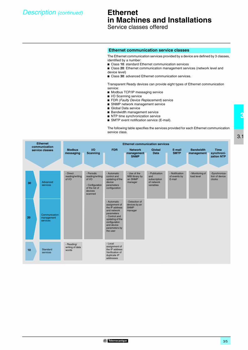
The Ethernet communication services provided by a device are defined by 3 classes, identified by a number:b Class 10: standard Ethernet communication servicesb Class 20: Ethernet communication management services (network level and device level)b Class 30: advanced Ethernet communication services.
Transparent Ready devices can provide eight types of Ethernet communication service:b Modbus TCP/IP messaging serviceb I/O Scanning serviceb FDR (Faulty Device Replacement) serviceb SNMP network management serviceb Global Data serviceb Bandwidth management serviceb NTP time synchronization serviceb SMTP event notification service (E-mail).
The following table specifies the services provided for each Ethernet communication service class.
Ethernet communication service classes
Ethernet communication service classes
30
20
10
Ethernet communication services
Modbus messaging
I/OScanning
FDR Network management
SNMP
GlobalData
Bandwidth management
Time synchroni-zation NTP
Advanced services
Communication management services
Standard services
- Direct reading/writing of I/O
- Periodic reading/writing of I/O
- Configuration of the list of devices scanned
- Use of the MIB library by an SNMP manager
- Automatic control and updating of the device parameters configuration
- Automatic assignment of the IP address and network parameters- Control and updating of the configuration and device parameters by the user
- Local assignment of the IP addressVerification of duplicate IP addresses
- Monitoring of load level
-Synchroniza-tion of device clocks
- Publication and subscription of network variables
- Reading/writing of data words
- Detection of devices by an SNMP manager
E-mailSMTP
- Notification of events by E-mail

3/6
3
3.2
Product data sheet Ethernetin Machines and Installations 0
Human-Machine Interface productsMagelis XBT GTtouch-sensitive graphic terminals
Magelis XBT GT (with 3.8” to 15” LCD touch screen) graphic terminals provide simple access to communication solutions via their direct connection to the Ethernet TCP/IP network.
Presentation
Characteristics and references
Touch screen graphic terminals Magelis XBT GTDisplay LCD screen size 3.8" 5.7” 7.5” 10.4” 12.1” 15"Memory capacity Application 8 MB
Flash EPROM16 MB Flash EPROM
32 MB Flash EPROM
Extension – By Compact Flash card 128, 256, 512 MB or 1 GBFunctions Representation of variables Alphanumeric, bitmap, bargraph, gauge, tank, curve, polygon, button, light
Curves Yes, with logAlarm log Yes
Communication Integrated Ethernet (RJ45) 10BASE-T 10BASE-T/100BASE-TXDownloadable protocols Uni-TE, Modbus, Modbus TCP/IP and third-party protocols
Compatibility with PLCs Twido, Modicon M340, Modicon Premium, Modicon Quantum
Configuration software Vijeo Designer VJD ppD TGS V44M (on Windows 2000 and XP)Operating systems MagelisCompact Flash card slot – Yes
Dimensions W x H x D (mm) 130 x 104 x 41 167.5 x 135 x 59.5
215 x 170 x 60 313 x 239 x 55 (2)
313 x 239 x 56 395 x 294 x 60
Supply voltage c 24 VReferences Back-lit monochrome STN screen XBT GT1130
(1)XBT GT2130 – – – –
64-color STN screen – – XBT GT4230 XBT GT5230 – –256-color TFT screen – XBT GT2330 XBT GT4330 XBT GT5330 XBT GT6330 –256-color TFT screen with video input – – XBT GT4340 XBT GT5340 XBT GT6340 XBT GT7340
Separate partsMagelis XBT GT terminals Compact Flash memory cards 128 MB 256 MB 512 MB 1 GbReferences XBT ZGM128 XBT ZGM256 MPC YN0 0CFE 00N MPC YN0 0CF1 00N
(1) With 6 function keys R1...R6.(2) For XBT GT5330/GT5340 : 270.5 x 212.5 x 57.
For further information, please consult our “Human-Machine Interface” catalog.

3/7
3
3.2
Product data sheet Ethernetin Machines and Installations 0
Human-Machine Interface productsMagelis XBT F graphic terminals
Magelis XBT F 10.4” (with keypad or touch screen) graphic terminals provide simple access to communication solutions via their direct connection to the Ethernet TCP/IP network.
Presentation
Characteristics and references
Graphic terminals Magelis XBT FDisplay LCD screen size 10.4”
Memory capacity Application 16 MB Flash EPROM (via PCMCIA type II card)Extension –
Data entry keypad Soft function keys with LED 10 –
Static function keys with LED 12 + legends –Service keys 12 –Alphanumeric keys 12 + 3
alphanumeric access
–
Touch-sensitive keys – – 8 in 1 row 16 in 2 rows 12 in 2 columnsTouchscreen data entry – Yes
Functions Representation of variables Alphanumeric, bitmap, bargraph, gauge, potentiometer, selectorRecipes 125 records maximum with 5000 valuesCurves 16 real-time curves
Alarm log YesCommunication Integrated Ethernet 10BASE-T/100BASE-TX (RJ45)
Buses and networks Fipio, Fipway, Modbus Plus
Downloadable protocols Uni-TE, Uni-TE TCP, Modbus, Modbus TCP/IP and third-party protocolsCompatibility with PLCs Twido, Modicon M340, Modicon Premium, Modicon QuantumConfiguration software XBT L1003M (on Windows 98, 2000 and XP)
Operating systems MagelisDimensions W x H x D (mm) 296 x 91 x 332 296 x 91 x 222 296 x 95 x 222Supply voltage c 24 V
References 256-color TFT screen XBT F024610 XBT F034610 XBT FC044610 XBT FC084610 XBT FC064610
Separate partsMagelis XBT F Graphic terminals
PCMCIA memory card 16 MB – – –PCMCIA card for connection to Fipio bus Fipway network Modbus Plus network
References XBT MEM16 TSX FPP 10 TSX FPP 20 TSX MBP 100

3/8
3
3.2
Product data sheet Ethernetin Machines and Installations 0
Human-Machine Interface productsMagelis Smart iPC industrial PCs
Magelis Smart iPC industrial PCs are "hardened" PCs, which do not feature vulnerable components: hard disk, CD-ROM drive, etc. They are equipped with a 12" or 15" active-matrix backlit color TFT LCD touch screen
b 12” models (MPC ST2 1NAJ 10T/R ) have a 100…240 V power supply and feature in particular two Ethernet 10BASE-T/100BASE-TX ports (RJ45 connectors) and a total of 5 USB ports, one of which is located on the front panel.b 15” models (MPC ST5 2NDJ 10T/R ) have a c 24 V power supply, 1 Ethernet port and 2 USB ports.
Magelis Smart iPC industrial PCs feature a Windows XPe SP2 operating system and are supplied ready-to-use in two configurations:b Web edition: MPC STp pNpJ 10T, with application software pre-installed on a 1-GB Flash memory card:v Internet Explorer for browsing the Web (Internet/Intranet)v Windows Terminal Services client for client/server architecturesv Software (readers) for reading Word (.doc), Excel (.xls), PowerPoint (.ppt), and Acrobat (.pdf) filesb HMI edition - Vijeo Designer RT: MPC STp pNpJ 10R, with the software components listed above pre-installed on a Flash card, plus:v Vijeo Designer Run Time software
Presentation
Characteristics and references
Compact industrials PCs Smart iPCDisplay Size 12" XGA (800 x 600) 15” XGA (1024 x 768)
Format TFT active matrix back-lit color LCD (262,144 colors)Data entry Via touchscreenProcessor Format Intel Celeron M VIA
Frequency 600 MHz 667 MHzEthernet TCP/IP Network 2 x 10BASE-T/100BASE-TX (RJ45) 1 x 10BASE-T/100BASE-TX (RJ45)Storage 1 GB Compact Flash
RAM 256...1024 MB 256...512 MBCD-ROM drive –Expansion slots PCMCIA cards 1 slot (taking a maximum of 1 x type III card or
1 x type I card)1 slot (taking a maximum of 1 x type III card or 2 x type I cards)
PCI port –Compact Flash card 1 slot reserved for 1-GB card containing OS and software
Operating system Windows Xpe integrated Windows 2000 preinstalled
I/O ports 4 x USB 2 x USB, 1 x COM1, 1 x COM2, 1 x parallel1 x PS2 keyboard
On front panel 1 x USB –
Mounting On panel or cabinet door (8 fixing bolts supplied)Dimensions W x H x D (mm) 313 x 239 x 65 mm 395 x 294 x 65 mmPower supply a 100...240 V c 24 V
Edition Web MPC ST2 1NAJ 10T – MPC ST5 2NDJ 10T –HMI Vijeo Designer Run- Time – MPC ST2 1NAJ 10R – MPC ST5 2NDJ 10R
Separate parts 12" MPC ST2 NAJ 10p 15" MPC ST5 2NDJ 10pRAM expension kit 512 MB MPC YK0 5RAM 512 MPC YK0 2RAM 512
1024 MB MPC YK2 2RA1 024 –
Compact Flash memory 1 GB blank MPC YN0 0CF1 00N
1 GB, Web edition software pre-installed
MPC YN2 1CF1 00T MPC YN0 0CF1 52T
1 GB HMI edition Vijeo Designer RT software pre-installed
MPC YN2 1CF1 00R MPC YN0 0CF1 52R

3/9
3
3.2
Product data sheet Ethernetin Machines and Installations 0
Human-Machine Interface productsMagelis Compact iPC industrial PCs
Magelis Compact iPC industrial PCs are “hardened” PCs adapted to the restrictions of industrial environments, and combining compact dimensions with advanced performance and openness to applications under Windows 2000 or Windows XPpro.Powered by a a 100…240 V supply, they are equipped with a 12” or 15” active-matrix backlit color TFT LCD touch screen, a USB port on the front panel (in addition to the standard USB ports), a u 20 GB hard disk, a slot for a PCI card, and a slot for a PCMCIA card.
b 12” models MPC KT2 2NAp 00N (Intel Celeron M 1.3 GHz processor) feature in particular two Ethernet 10BASE-T/100BASE-TX ports (RJ45 connectors) and a total of 5 USB ports, one of which is located on the front panel.b 15” models MPC KT5 2NAp 00N (VIA 667 MHz processor) and MPC KT5 5NAp 00N (Intel Pentium 4M 1.7 GHz processor) feature 1 Ethernet port and 2 USB ports.
Magelis Compact iPC hardware is also available in the form of “packages”, which are supplied together with the application software listed below and are compatible with the relevant processor power:Vijeo Designer RT:References MPC KTp pNAp 00R
Presentation
Compact iPC - Hardware
Compact iPC - Software packages
Characteristics and references
Compact industrials PCs Compact iPCDisplay Size 12" XGA (1024 x 768) 15” XGA (1024 x 768)
Format TFT active matrix back-lit color LCD (262,144 colors)Data entry Via touchscreenProcessor Format Intel Celeron M VIA Pentium 4 Mobile
Frequency 1.3 GHz 667 MHz 1.7 GHzEthernet TCP/IP Network 2 x 10BASE-T/100BASE-TX
(RJ45)1 x 10BASE-T/100BASE-TX (RJ45)
Storage Hard disk u 20 GBRAM 512...1024 MB 512 MB
CD-ROM drive – Yes, 24xFloppy disk drive – Yes, 3.5", 1.44 MBExpansion slots PCMCIA cards 1 slot (taking a maximum of 1 x
type III card or 1 x type I card)1 slot (taking a maximum of 1 x type III card or 2 x type I cards)
PCI port 1 PCI bus slot
Operating system Windows 2000 or Windows XP ProI/O ports 4 x USB
1 x RS2322 x USB, 1 x COM1, 1 x COM2,1 x parallel2 x PS2
On front panel 1 x USB –Mounting On panel or cabinet door (8 fixing bolts supplied)Dimensions W x H x D (mm) 313 x 239 x 108 mm 395 x 294 x 108 mm
Software package – MPC KT2 2NAp 00N MPC KT5 2NAp 00N MPC KT5 5NAp 00NVijeo Designer Run Time MPC KT2 2NAX 00R MPC KT5 2NAX 00R MPC KT5 5NAX 00RVijeo Look Run Time – MPC KT5 2NAp 00A –Vijeo Look Built Time – – MPC KT5 5NAp 00B
Separate parts 12" modelsMPC KT2 2NAp 00N
15" models
MPC KT5 2NAp 00N MPC KT5 5NAp 00NRAM expansion Kit 512 MB MPC YK0 5RAM 512 – MPC YK0 2RAM 512 MPC YK0 5RAM 512
1024 MB – MPC YK2 2RA1 024 – –

3/10
3
3.2
Product data sheet Ethernetin Machines and Installations 0
Human-Machine Interface productsMagelis Modular iPC industrial PCs
The main features of the Magelis Modular iPC range of industrial PCs are:b Modularity in respect of power ratings and expansion options for Control box 102 and Control box 402.b Integration of diagnostic tools designed to facilitate operation and maintenance.
The Magelis Modular iPC offer comprises:b Three front panels with 15” color TFT LCD screen.b Control box 102 and Control box 402.
Magelis iPC front panel screens for mounting on a Control box 102/402 comprise:b A 15” TFT active matrix backlit color LCD screen, with or without touch-screen capability, depending on the modelb An infrared IrDA-compatible portb A connector for the PS/2 keyboard or mouse port, protected by a plug
With the keyboard model:b A standard IBM 70-key keyboard b 2 x 10 user-configurable keysb A pointing device with tactile feedback
Presentation
Characteristics and references
Screens for Modular iPC industrial PCs (any screen can be used with any type of Control box)
Display LCD screen size 15" XGA (1024 x 768)Format TFT active matrix back-lit (262,144 colors)
Data entry By Keyboard Keyboard and touchscreen Touchscreen
Alphanumeric keys 70 standard IBM keys –User function keys 2 x 10 keys –
Touch panel Analog resistive, 35 million cyclesI/O ports 1 PS/2 port for keyboard/mouse and pointing device
1 IrDA compliant infrared portMounting On any Control box MPC EN0/DN0 listed belowPower supply Via Control box
Dimensions (W x H x D) 480 x 370 x 53 mm 480 x 370 x 53 mm 460 x 340 x 53 mmReferences MPC NA5 0NNN 20N MPC NB5 0NNN 20N MPC NT5 0NNN 20N

3/11
3
3.2
Product data sheet (continued)
Ethernetin Machines and Installations 0
Human-Machine Interface productsMagelis Modular iPC industrial PCs
Modular iPC Control boxes will feature one of the 15” MPC Np5 front panels and are equipped with:b An Intel Celeron M 1.3 GHz or Intel Pentium M 1.6 GHz processorb A 40 MB hard disk, minimumb 512 MB of RAM as standard, expandable to 4 GBb A floppy disk driveb A removable CD-ROM drive (1)b A TCP/IP, 10BASE-T/100BASE-TX, 10/100 Mbps Ethernet port (RJ45 connector)b Two 12 Mbps USB portsb Two serial COM ports (RS 232)b One parallel portb Windows 2000 or Windows XP Pro operating system pre-installed
Presentation
Characteristics and references
Control boxes Control box 102 Control box 402Processor Format Intel Celeron M Intel Pentium M Intel Celeron M Intel Pentium M
Frequency 1.3 GHz 1.6 GHz 1.3 GHz 1.6 GHzStorage Hard disk u 40 GB, removableRAM SDRAM 256 MB, expandable to 512 MB (2 memory slots maximum)
CD-ROM drive Yes, removable, 24x or combined DVD-R/CD-RW drive (available as an option)Floppy disk drive 3.5", 1.44 MBExpansion slots 1 x PCI bus slot and
2 x type 1/2 (or 1 x type III) PCMCIA slots4 x PCI bus slots and2 x type 1/2 (or 1 x type III) PCMCIA slots
Integrated Ethernet TCP/IP port 1 x 10BASE-T/100BASE-TX (RJ45)
I/O ports 2 x USB, 1 x COM1, 1 x COM4, and 1 x parallel, 1 x VGA external video port, 2 x PS/2 port (1)Mounting b With front panel screen: on panel or cabinet door (fixing bolts supplied with each unit). On 19"
rack with 15" front panel screen, requires mounting accessory MPC YNO 0RMK 00N.b Without front panel screen: on panel or cabinet door, requires mounting panel MPC NP0 0NNN 00N.
Operating system Windows XP Pro or Windows 2000 operating system pre-installed
Dimensions W x H x D (mm) 310 x 310 x 155 310 x 310 x 245Power supply a 100…240 V MPC EN0 2NAp 00N MPC EN0 5NAp 00N MPC DN0 2NAp 00N MPC DN0 5NAp 00N
c 24 V MPC EN0 2NDp 00N MPC EN0 5NDp 00N MPC DN0 5NDp 00N MPC DN0 5NDp 00N
(1) Port not operational when the Control box is fitted with the front panel screen.
Nota : Operating system: Replace p with X to order the model with Windows XP Pro installed or with A to order the model with Windows 2000 pre-installed.
Modular Magelis iPC-Vijeo Look software combined offers Control box 102 Control box 402Processor Intel Celeron, 1.3 GHz Intel Pentium, 1.6 GHzExpansion card slots 1 x PCI slot
2 x PCMCIA slots4 x PCI slots2 x PCMCIA slots
Vijeo Look supervisory software (see page 3/14) Run Time (RT) monitoring Run Time (RT) monitoring Build Time/Run Time (BT/RT) monitoring
Power supply a 115…230 V MPC EN0 2NAX 00A MPC DN0 5NAX 00A MPC DN0 5NAX 00B
Separate partsRAM expension kit (2) 512 MB 1 GBPower supply a 115…230 V MPC YDE RAM0 512 MPC YDE RAM1 024(2) Control box 102 and 402 units have 2 slots for RAM cards (one of wich has a 512 MB RAM card installed as standard).

3/12
3
3.2
Product data sheet Ethernetin Machines and Installations 0
Human-Machine Interface productsMagelis iDisplay flat screens
Magelis iDisplay screens are monitors with industrial flat screens designed for use in conjunction with PCs.The screen is availables in size 15”. Featuring the latest TFT LCD technology, they offer top-class visualization and extended service life. Their touch screen interface makes for easy setup of user-friendly and high-performance HMI interfaces.
Certified in accordance with PLC product standards, designed for use in harsh industrial environments and offering an excellent screen size/dimensions ratio, they can be installed easily on any machine and in any device, and are suitable for use in any type of environment.
With identical dimensions to and a screen the same size as Magelis Smart iPC and Compact iPC industrial PCs, Magelis iDisplay screens can be used to visualize the development of installations with optimum ease and simplicity.
Presentation
Characteristics and references
Type 15"Screen Resolution XGA 1024 x 768
Type Active-matrix color TFT LCD
Number of colors 16 777 216Brightness u 200 cd/m2 adjustableBacklighting (service life) 50,00 hours
Product certification UL 508, CSA, IEC 61131-2Temperature in operation 0 to +50°C, compliant with EN 61131-2, UL
in storage -10 to +60°C, compliant with IEC 68-2-2 tests Bb and Ab, IEC 68-2-14 test Na, and EN 61131-2
IP level IP 65Product certification UL 508, CSA, IEC 61131-2Touch panel Analog resistive, 35 million cycles
Inputs Image VGA or DVI-D portOutputs Touch panel USB or RS 232C portPower supplyI
Voltage ratings a 100 to 240 V (threshold values 98 to 264 V), EN 61131-2-compliant
Frequencies 50/60 Hz (threshold values 47/63 Hz), EN 61131-2-compliantMicro-breaks y 20 ms
Power consumption 120 VA
Dimensions W x H x D (mm) 395 x 294 x 65Mounting Magelis iDisplay flat screens MPC YT5 can be mounted on a panel or cabinet door (fixing parts
supplied). Cable 3 meters includedPower supply a 100…240 V MPC YT5 0NAN 00N MPC YT9 0NAN 00N

3/13
3
3.2
Product data sheet Ethernetin Machines and Installations 0
Human-Machine Interface productsFactoryCast HMI software
FactoryCast HMI application development software, referenced TLX CD FCHMI V1M, provides multiproject management and complete control of FactoryCast HMI applications, during both the development and the debugging phases, thanks to the online mode and simulation mode (operational when the system is offline) options.
This software enables the intuitive and user-friendly setup of HMI functions by simply setting parameters using a tree structure of the application and can be used for complete management of the Web site:
b Setting parameters for HMI functions:v Configuration of PLC interfaces: Import symbol databases and set parameters for the acquisition periodv Configuration of spreadsheetsv Configuration of E-mailv Configuration of connections to databasesv SOAP/XML client /server interface (see page 7/5)v Recipe management
b Management of the Web site:v Management of the Web site tree structure (creation/deletion of HTML folders and files)v Management of default Web site pagesv Management of user Web site pages (1)v Graphic object editor for animating Web pagesv Launch of the system editor for HTML pages (FrontPage or similar)v Up/downloading/comparison of Web pages in online modev Debugging of Web pages in online mode or in simulation mode (including animations and Java beans)
b Simulation modeThe application and the Web site (including animations and Java beans) can be debugged in either online or simulation mode, which enables operation to be tested without a FactoryCast HMI module and without a physical connection to a PLC, thus simplifying debugging.
An integrated graphics editor in the FactoryCast HMI software can be used to easily customize the following graphic objects: bar charts, gauges, LEDs, curves, cursors, operator input fields, alphanumeric display fields, buttons, etc.User Web pages are created graphically using an external HTML editor (FrontPage or similar, not supplied).FactoryCast HMI includes a plug-in for FrontPage 2000. This plug-in makes it easier to set up animations, which enable PLC variables to be accessed in realtime in the HTML pages created by the user. They are created in the HTML editor by simply inserting customized graphic objects (FactoryCast Java beans).
(1) Creation of user Web pages: User Web pages created in the FactoryCast HMI environment are actual animated supervision screens and can be used to monitor your process. Based on HMI Web technology, they enable realtime access to PLC variables thanks to the FactoryCast graphic objects library (FactoryCast Java beans).
Web application development, FactoryCast HMI software
ReferencesFactoryCast HMI modulesActive Web server Module for
automation platformData rate Reference Weight
kg FactoryCast HMI Modicon Premium 10/100 Mbps TSX WMY 100 0.340
Modicon Quantum 100 Mbps 140 NWM 100 00 -
TSX WMY 100
140 NWM 100 00
FactoryCast HMI installation software (to be ordered separately)
Name and description
Use Operating system
Reference Weightkg
Multilingual FactoryCast HMI (1)
Development and debugging of the HMI application
Windows 2000, Windows XP
TLX CD FCHMI V1M 0.340
(1) Includes documentation in electronic format.

3/14
3
3.2
Product data sheet Ethernetin Machines and Installations 0
Human-Machine Interface productsVijeo Look control software
Vijeo Look version 2.5 is a SCADA (Supervisory Control And Data Acquisition) software package designed for standalone stations. It is based on open, standardized technologies, similar to Transparent Ready products. For example, it provides the ability to display pages in Modicon PLC embedded Web servers.
It is easy to implement and offers all the standard functions of a graphic supervision tool. Vijeo Look is supplied with a pre-configured OFS (OPC Factory Server, see page 3/17) data server. It is compatible with PCs running Windows 2000 Professional or Windows XP Professional, and is used for creating applications based on Telemecanique Twido, Modicon TSX Micro, Modicon Premium/Atrium/Momentum/Quantum PLCs.
The functions of Vijeo Look supervisory software can be used for:b Acquisition of PLC tagsb Visualization of these tagsb Process supervision and controlb Recording the values of PLC tags or internal process tags in a databaseb Embedded software processing
PLC tags are acquired exclusively by connecting to the PLCs via the OPC server, supplied with the OFS data server software included with Vijeo Look.In the case of discrete and analog I/O tags from TSX Micro/Premium/Quantum PLCs (and Advantys STB/Momentum/TBX remote I/O), the acquisition process in the Vijeo Look database takes place in an implicit, transparent manner.As an OPC server, Vijeo Look enables you to create and enhance tags, as well as make them available.
The Vijeo Look offer includes 2 types of software license:b Build Time/Run Time license (BT/RT) allowing the application to be built and runb Run Time license (RT) allowing the application built with the RT/BT license to run
There are four I/O sizes offered for each license type: Small (128 I/O), Medium (512 I/O), Large (1024 I/O) and Extra Large (2048 I/O).
Presentation
Logging
Processing
Visualization
Communication
Structure of the offer
ReferencesVijeo Look software
Compatibility Twido, Modicon TSX Micro/Momentum/Premium/Atrium/Quantum PLCs
Operating system Windows 2000 Professional or Windows XP ProfessionalType of license Small, 128 I/O Medium, 512 I/O Large, 1024 I/O Extra Large, 2048 I/OReferences Build Time/Run Time (BT/RT) VJL SMD BTS V26M VJL SMD BTM V26M VJL SMD BTL V26M VJL SMD BTX V26M
Run Time (RT) VJL SMD RTS V26M VJL SMD RTM V26M VJL SMD RTL V26M VJL SMD RTX V26M

3/15
3
3.2
Product data sheet 3 Ethernetin Machines and Installations 3
Human-Machine Interface productsVijeo Citect supervisory software
The Vijeo Citect supervisory software offer is characterized by its flexibility, allowing customers to build the supervision solution that corresponds to their needs.
Vijeo Citect features and power makes it suitable for any application in any market, in most demanding fields:v Energy and Infrastructure: Airports, Roads & tunnels, Water, Oil & Gas.v Industry: Food & Beverage, Mining, Metal, Minerals.
The flexible architecture in vijeo Citect software and applications make the investments are always scalable, and durable.
From small stand-alone system, to large distributed redundant multiple network systems, only one single development tool needs to be used: this dramatically reduces training and knowledge management costs, optimizing the investments.
As Vijeo Citect is perfectly aligned with Schneider Electric’s control/HMI/SCADA offer development strategy, designers and users take full benefit from single accountability with Schneider Electric for system integration and performance.
Vijeo Citect exists:v in a Client-Server architecture, ranging from 75 Points to an unlimited number of Pointsv in a stand-alone version called Vijeo Citect Lite that can manage up to 1200 PointsEach Server license includes a Server Client and OFS. OFS allows a Vijeo Citect SCADA application, as a “client”, to access any data in any Schneider Electric control system and electrical distribution device connected to networks or fieldbuses, in real time. It also allows communication with third-party devices supporting Modbus and Modbus TCP protocols.
Four types of Clients are available:v Display Clients, used by operators accessing the Vijeo Citect Server thru a local connection.v Manager Clients, for user who not need to get a view of the Vijeo Citect application with no control, thru local connection.v Web Display Clients: same as Display Clients, thru a Web connection.v Web Manager Clients: same as Manager Clients, thru the Web..
v Static Client license: For operators who need to have access to the control system at any time, whatever the number of Clients currently connected to the Server is. Resides in a physical key plugged into the operators’s Client PC.v Floating Client license: For users who need to use the Client occasionally. Connections are allowed until the number of floating licenses purchased has been reached. Stored on the Server key.v Redundancy Client license: For a Standby Server in a Redundant configuration.
Presentation
Single server architecture with 2 Web Clients
Single server architecture with 3 Client licenses: 2 floating and 1 static
Server and its Client
Static licenseFloating licenses
Server licenses
Client licenses
Static, Floating and Redondancy Client licenses
CharacteristicsCompatibility All Modicon PLCs and all automation systems using the OPC standard (OFS)
Operating system Windows XP Pro, Windows 2000, Windows Server 2003Sizes 75, 150, 500, 1500, 5000, 15000, unlimited number of PointsLicense types v Server, Client, Redundant
v Vijeo Citect Lite: Stand-alone system, 300, 600 or 1200 PointsClient types v Display
v Web Displayv Managerv Web Manager
Development workshop Delivers components: CD including Vijeo Citect, OFS, Schneider Electric drivers pack, hardware key(s), installation guide
Hardware keys USB or parallelEvaluation license Runs in stand-alone modeSupport Includes technical support and upgrades. (1 year included at purchase)
References Please contact your Regional Sales Office

3/16
3
3.2
Product data sheet Ethernetin Machines and Installations 0
Human-Machine Interface productsMonitor Pro SCADA software
Monitor Pro V7.6 is a SCADA (Supervisory Control and Data Acquisition) software solution. Its high-performance real-time server offers excellent processing capability, mainly due to the application objects. In addition, its client-server architecture on Ethernet TCP/IP enables it to be easily integrated in architectures based on Transparent Ready products: multi-server for sharing processing, multi-user for wide distribution of information, or in redundancy mode for your “high availability” applications.
b The graphic interface offers a library of graphic objects. Based on Windows technology, the interface is easy to customize.b Configuration Explorer: an intuitive environment for configuring the real-time data server and for object-oriented configuration.b The relational database access interface, supplied with SQL Server 2000. Monitor Pro V7.6 makes it easy to record production data or access stored information. Monitor Pro V7.6 also operates with Oracle, Sybase, Dbase IV and all other databases that support the ODBC standard.b Improved availability: Monitor Pro incorporates redundancy services ensuring a high level of architecture availability.b Integrated traceability functions, for real-time monitoring of the quality of your production as well as logging all the actions of the operators.
Monitor Pro V7.6 is the supervisory software package that adapts to your needs. It offers you real-time production monitoring and enables you to optimize the use of your equipment.
Description
Multi-level architecture
Monitor ProBuild Time/Run
client stations
Monitor ProBuild Time
server stations
Data/information
Redundancy
CharacteristicsFormat Control software
Compatibility All Telemecanique PLCs and all automation systems on the market via communication drivers or using the OPC standard
Operating system Windows 2000 service Pack 3, Windows XP or Windows Server 2003Input/Output size 11 sizes, from 300 I/O to an unlimited number of I/O (from 4800 tags to an unlimited number)
Version Build Time/Run Time (BT/RT) or Run Time (RT)PC CD-ROM references Please contact your Regional Sales Office

3/17
3
3.2
Product data sheet Ethernetin Machines and Installations 0
Human-Machine Interface productsOPC Factory Server
Based on the OLE for Process Control (OPC) standard, Telemecanique's OPC Factory Server (OFS) software allows “client” software applications, such as supervisors/SCADA and customized interfaces, to access the data of Schneider Electric control system and electrical distribution devices connected to networks or fieldbuses in real time.It also allows communication with third-party devices supporting Modbus and Modbus TCP protocols.
In version V3.3, the OFS data server integrates the most recent specifications of the OPC Foundation:b OPC-DA (OPC Data Access)b .NET API interface b OPC XML-DA V1.0 (OPC XML Data Access)
OFS software can be integrated in control system architectures as shown below:
The OFS server 1 is at the center of the data exchanges.The direct and dynamic link 2 between the OFS server and the Unity Pro project station results in productivity gains for designers and users of the devices.OFS has direct access to the items in the Unity Pro project. In addition, it performs a consistency check between these items and those of the Premium and Quantum PLCs.
The OFS V3.3 offer comprises:b OPC server softwareb OPC server simulator (for debugging the application when no PLCs are present)b OFS server configuration softwareb An example of OPC client for setting up applicationsb The setup documentation on CD-ROMSupplied on CD-ROM, the software operates independently on a PC. It interfaces with the variable export files generated by PL7, ProWORX, Concept, and Unity Pro software. It also provides a direct and dynamic link to the Unity Pro and Concept applications (1).The OFS V3.3 offer is available in two levels:b OFS Small: data server for 1000 items (2) that does not support the OPC XML-DA protocol b OFS Large: complete data server
(1) Requires Concept version > 2.0 software to be installed on the same station.(2) item: variable, structure, table etc. in the Unity Pro application.
Description
1
2
Ethernet TCP/IP
OFS server (V3.0)
Database
Symbols.xvm (Unity Pro)Symbols.prj (Concept)Symbols.scy (PL7)
Premium
Modicon M340Momentum
QuantumEthernet TCP/IP
Unity Pro project station
OPC client
Structure of the offer
ReferencesOFS data server software
Operating system Windows 2000 Professional or Windows XPType of license Single station 10 stations 200 stations
References OPC Factory Server V3.3 Small software TLX CD SUOFS 33 TLX CD STOFS 33 –OPC Factory Server V3.3 Large software TLX CD LUOFS 33 TLX CD LTOFS 33 TLX CD LFOFS 33

3/18
3
3.3
Product data sheet Ethernetin Machines and Installations 0
Controllers and PLCsModicon Momentum M1E processor adapter
M1 processor adapters with embedded Web server are based on the Modicon Momentum distributed I/O family of products. They are designed to be stand alone for mounting on any discrete, analog or application-specific I/O base. Depending on the type, they take one of the following:b Remote I/O via the I/O bus portb Connection of a Modbus Fmaster/slave bus.
An optional module inserted between the M1 processor and the I/O base enables these units for network connection. The Flash memory can also be used to back up the applications, creating a local copy of the program to be loaded in the RAM.
Either ProWORX 32 software (LL984 programming) or Concept software (5 IEC languages) is required for programming M1 processor adapters, depending on the model.
M1E 171 CCC 960 20/30 and 171 CCC 980 20/30 processor adaptershave the following on the front panel:1 A standard (RJ45) connector for 10BASE-T interface.2 A 9-way female SUB-D connector for Modbus or I/O bus connection (depending
on the model).3 Three LED indicators.
Presentation
M1E processor adapter on Momentum I/O base
Description
1 23
CharacteristicsType of module 171 CCC 980 20 171 CCC 980 30 171 CCC 960 20 171 CCC 960 30
Transparent Ready services
Class B10
Web services “Rack Viewer” access to the product description and status, and to the island diagnostics“Data editor” access to the configuration functions and variables“Web page loader” software tool for loading user Web pages
Ethernet TCP/IP communication management services
Modbus Messaging (read/write data words)I/O Scanning
Structure Physical interface 10BASE-T
Data rate 10 MbpsMedium Twisted pair
Network module Operating temperature 0…+60 °C
Relative humidity 10...95% non condensing during operationDegree of protection IP 20Power supply Supplied by the 170 App I/O base on which the processor is mounted
Processor scan time 0.3 ms per KinstructionRAM/Flash memory 512 K/512 K 544 K/1 M 512 K/512 K 544 K/1 MUser memory/data memory 18 K/24 K
Programming software ProWORX 32 Concept, ProWORX 32
ProWORX 32 Concept, ProWORX 32
Other communication ports 1 RS 485 Modbus port 1 I/O bus (derived from INTERBUS)Communication extension ports Via optional modules (1 Modbus Plus port, 1 redundant Modbus Plus port, 1 serial link)Conformity to standards UL, cUL, FM Class 1 Division 2, NEMA type 250, eLED indicators Adapter operating (RUN)
Ethernet network status (LAN Act), Ethernet network activity (LAN STS)
ReferencesDescription Communication
portsProgramming Reference Weight
kgM1E processors
Class B10
1 Ethernet,1 Modbus
ProWORX 32 171 CCC 980 20 0.042Concept,ProWORX 32
171 CCC 980 30 0.042
1 Ethernet,1 I/O bus
ProWORX 32 171 CCC 960 20 0.042Concept,ProWORX 32
171 CCC 960 30 0.042
Accessories and separate parts: Please consult the “Modicon Momentum automation platform” catalog.
171 CCC 980/960 p0

3/19
3
3.3
Product data sheet Ethernetin Machines and Installations 0
Controllers and PLCsTwido compact base
The Twido range of PLCs provides a compact base with integrated Ethernet port. The TWD LCAE 40DRF base is a compact-sized (95 x 90 x 70 mm), “all-in-one” solution. It uses a 100…240 Va power supply and has the following discrete I/O:b 24 x 24 Vc inputsb 14 relay outputsb 2 x 24 Vc transistor outputs.This base can take:b Up to 7 I/O expansion modules, thus increasing the I/O capacity to 152 (with screw terminal version) or 264 (with HE 10 connector version)b All Twido range separate parts (memory cartridge or real-time clock, serial link adapters, digital display).
The TWD LCAE 40DRF Twido compact PLC base with integrated Ethernet port consists of:1 An RS 485 serial link port mini-DIN connector (for connecting the programming
terminal).2 A slot for diagnostics/maintenance digital display unit.3 Screw terminals for the 24 Vc sensor power supply and for connecting the input
sensors (protected by hinged terminal covers).4 A connector for expansion modules (7 modules max: discrete I/O, analog I/O,
AS-Interface bus). 5 An LED display block.6 Screw terminals for connecting the output preactuators (protected by hinged
terminal covers).7 Two analog adjustment points.8 A connector for the extension of the 2nd RS 232C/RS 485 serial link port.9 Screw terminals for connecting the 100...240 Va power supply.
Accessible from beneath the controller:10 A connector for memory cartridge or real-time clock.11 A standard (RJ45) connector for 10BASE-T/100BASE-TX interface.
Presentation
Twido compact base with display
Description
1 2
3
4
5
6
78910 11
CharacteristicsTransparent Ready services
Class A10Web services No Web serverStandard Ethernet TCP/IP communication services
Modbus messaging (read/write data words)BOOTP client for allocation of IP addresses via FDR server
Structure Physical interface RJ45 standard 10BASE-T/100BASE-TX connector
Data rate 10/100 Mbps with automatic recognitionMedium Twisted pair
Drive Operating temperature -0…+55 °C
Relative humidity 30...90% non condensingDegree of protection IP 20Power supply 100…240 Va, 50/60 Hz (limits 85…264 Va, 47…63 Hz)
24 Vc sensor power supply 250 mAInputs 24 x 24 Vc, 11 and 7 mA, type 1 inputs (positive or negative logic)Outputs 14 x 230 Va or 30 Vc, 2 A relay outputs
2 x 24 Vc, 1 A (positive logic) transistor outputsCounter 2 x 24 Vc 5 kHz channels, 2 x 24 Vc 20 kHz channelsProgramming TwidoSoft (Ladder language, Instruction List), 3000 instructions (6000 with memory cartridge)
Application memory 3000 instructions (6000 with memory extension cartridge)Conformity to standards IEC 61131-2, UL 508, UL 1604/CSA C22.2 No. 213 (Class 1 Division 2 Groups A, B, C, D), e
et TuVLED indicators Controller status (PWR, RUN, ERR and STAT), I/O (INp/OUTp)
Ethernet network status (LAN ST), 10 or 100 Mbps data rate (L ACT)
ReferencesDescription No. of discrete I/O Reference Weight
kgCompact base with integrated Ethernet port100…240 Va power supply
Class A10
24 x 24 Va inputs14 relay outputs2 solid state outputs24 Vc
TWD LCAE 40DRF –
Separate parts, I/O expansion modules, extension modules, prewired system and TwidoSoft programming software: Please consult our “Automation and relay functions” catalog.
TWD LCAE 40DRF

3/20
3
3.3
Product data sheet Ethernetin Machines and Installations 0
Controllers and PLCsTwidoPort, Ethernet Interface for Twido controllers
TwidoPort module 499 TWD 01100 is an Ethernet interface that is easy to use and dedicated to a compact or modular Twido programmable controller version ≥ 3.0. It allows incorporation of the Twido controller into an Ethernet network as a passive device (slave). With version 3.0 of TwidoSoft software and of the Twido operating system, the TwidoPort module is ready for use.When connected to the RS 485 port of the Twido programmable controller, the TwidoPort module acts as a gateway between the Ethernet network and the Modbus serial link.The connecting cable is supplied with the module.
The main characteristics of the TwidoPort module are as follows:b Connects to the RS 485 port of the Twido controller; no external auxiliary supply is necessary.b Ethernet configuration:v takes the Ethernet configuration from the Twido application configuration (normal mode),v supports manual configuration using Telnet.b Provides Ethernet statistics via a Telnet session
An optional type RS 485 link allow to have a second Modbus serial link to connect, for example, a Magelis XBT terminal for operator dialogue. This option is the TWD NAC 485D/485T serial interface adapter.
TwidoPort 499 TWD 01100 interface module comprises: 1 Five LEDs (SER ACT, STATUS, LINK, 100 MB, ETH ACT) indicating
performances associated with the TwidoPort module.2 An RJ45 connector for connection of the power supply and communications to the
RS 485 on the Twido controller, cable TWD XCA RJP03P supplied.3 An RJ45 connector (accessed through the bottom of the module) for connection
to the Ethernet TCP/IP network.4 An earthing screw (accessed through the bottom of the module).
Presentation
Ethernet TCP/IP
Modbus
Twido modular base controller
Description
2
1
3
4
CharacteristicsTwidoport module 499 TWD 01100
Transparent Ready services
Class A10Web server None
Standard Ethernet TCP/IP communication services
Modbus messaging (read/write data words)BOOTP functionauto MDI/MDX (no need cross over cable)Telnet for manual configuration and Ethernet statistics
Structure Physical interface RJ45 standard 10BASE-T/100BASE-TX connectorData rate 10/100 Mbps with automatic recognition
Medium Twisted pairTwidoPort interface Operating temperature 0...55 °C
Relative humidity 10…95 % (without condensation)
Degree of protection IP 20Max. consumption at c 5 V 180 mASupply voltage 5 ± 0.5 supplied by compact or modular Twido programmable controllerConformity to standards UL 508, CSA 1010, FCC Class A, EN 61131-2, eLED indicators Modbus serial link activity (SER ACT), STATUS, Ethernet link status (LINK), 100 Mbps data rate
(100 MB), Ethernet network activity (ETH ACT)
ReferenceDescription Characteristics Reference Weight
kgTwidoPort interface modulefor all base controllers version ≥ 3.0
Class A10
10/100 Mbps. Auto MDIX function. RJ45 connector.TWD XCA RJP03P cable supplied.
499 TWD 01100 0.200
Separate parts, base controllers, I/O expansion modules, extension modules, prewired system and TwidoSoft programming software: Please consult our “Automation and relay functions” catalog.
499 TWD 01100

3/21
3
3.3
Product data sheet (continued)
Ethernetin Machines and Installations 0
Controllers and PLCsModicon M340 processors with integrated Ethernet port
Robust, powerful and compact, the new Modicon M340 PLC is the ideal solution for machine manufacturers in applications such as secondary packaging, materials handling, textiles, printing, food processing, woodworking machines, ceramics, etc. The integration of Altivar and Lexium variable speed drives, Magelis display units and Preventa safety modules has been boosted in order to simplify the setup and use of Telemecanique solutions.
BMX P34 2020 and BMX P34 2030 Modicon M340 processors with integrated Ethernet port have the following on the front panel:1 Safety screw for locking the module in its slot (marked 0) in the rack2 A display unit including at minimum 3 LEDs relating to the Ethernet port.3 A mini B USB connector for a programming terminal (or Magelis XBT GT operator
interface) (1)4 A slot equipped with its Flash memory card for saving the application and
activating the standard Web server, Transparent Ready class B10 .5 An RJ45 connector for connection to the 10BASE-T/100BASE-TX Ethernet
TCP/IP networkAlso included, depending on the model:6 BMX P 34 2020 processor: An RJ45 connector for the Modbus serial link or
character mode link (RS 232C/RS 485, 2-wire, non-isolated)7 BMX P 34 2030 processor: A 9-way SUB-D connector for the master CANopen
machine and installation busOn the back panel: 2 rotary switches for assigning the IP address.
Presentation
Description
6
2
3
5
1
4
7
CharacteristicsModule type Unity Pro software BMX P34 2020 BMX P34 2030
Transparent Ready services
Class B10Standard Web server Rack Viewer access to the product description and status and to the PLC diagnostics
Data Editor access to the configuration functions and PLC variablesStandard Ethernet TCP/IP communication service Modbus TCP messaging (read/write data words)
Ethernet TCP/IP advanced communication services
I/O Scanning –Global Data –FDR Client Automatic assignment of IP address and network parameters
SMTP E-mail notification –SNMP network administrator YesBandwidth management Yes
Structure Physical interface 10BASE-T/100BASE-TX (RJ45)Data rate 10/100 Mbps with automatic recognitionMedium Twisted pair
Modicon M340 processor
No. of discrete I/O 1024No. of analog I/O 256No. of application-specific channels 36
Max. no. of Ethernet TCP/IP connections 2 (integrated port and BMX NOE 0100 network module)Other integrated communication ports Modbus serial link or character mode CANopen busOperating temperature 0…+ 60 °C
Relative humidity 10...95% non condensing during operationDegree of protection IP 20Power supply Via the power supply of the rack supporting the processor
Conformity to standards IEC/EN 61131-2, UL 508, CSA 22.2 n°142, CSA 22.2 n°213 Class 1 Division 2 , eLED indicators Activity on the Ethernet TCP/IP network (ETH ACT, green)
Status of the Ethernet TCP/IP network (ETH STS, green)Data rate on the 10 or 100 Mbps Ethernet TCP/IP network, (ETH 100, red)4 LEDs specific to processor operation (RUN, ERR, I/O, CARD ERR) 1 or 2 LEDs specific to the other communication ports (SER COM or CAN RUN and CAN ERR) (2)
ReferencesDescription I/O capacity
Memory capacityOther integrated communication ports
Reference Weightkg
Processors with integrated Ethernet link
Class B10
1024 discrete I/O 256 analog I/O 36 app-sp. channels
4096 Kb integrated
Modbus serial link or character mode
BMX P34 2020 0,205
CANopen bus BMX P34 2030 0,215
(1) The Magelis XBT GT graphic terminal requires Vijeo Designer configuration software version 4.5. Available 1st quarter 2007.
(2) SER COM for serial link or CAN RUN and CAN ERR for CANopen bus.BMX P34 2020 BMX P34 2030

3/22
3
3.3
Product data sheet Ethernetin Machines and Installations 0
Controllers and PLCsModicon M340 Ethernet network modules
The BMX NOE 0100 module is a standard module occupying a single slot in the rack of the Modicon M340 platform equipped with a Standard processor or associated Performance processor (maximum of 1 module per configuration).Depending on the memory card it is equipped with, the Web server is Transparent Ready class B30 or C30
LThe BMX NOE 0100 module has the following on the front panel:1 Safety screw for locking the module in its slot (marked 0) in the rack2 A display unit consisting of 6 LEDs3 A slot equipped with its Flash memory card for activating the standard Web server,
Transparent Ready class B30. This card can be replaced by the BMX RWS C016M card, Transparent Ready class C30
4 An RJ45 connector for connection to the 10BASE-T/100BASE-TX Ethernet TCP/IP network
5 A pencil-point RESET pushbutton for a cold restart of the moduleOn the back panel: 2 rotary switches for assigning the IP address in one of 3 modes: v Address set by the position of the two switchesv Address set by the application parametersAddress set by the Ethernet TCP/IP network BOOTP server.
Presentation
Description
5
2
4
1
3
CharacteristicsModule type Unity Pro software BMX NOE 0100 BMX NOE 0100 + BMX RWS C016M
Transparent Ready services
Class B30 C30Standard Web server Rack Viewer access to the product description and status and to the PLC diagnostics
Data Editor access to the configuration functions and PLC variablesConfigurable Web server Yes Yes
User Web pages (available size) – Yes (16 Mb)Standard Ethernet TCP/IP communication service Modbus TCP messaging (read/write data words)Ethernet TCP/IP advanced communication services
I/O Scanning Yes
Global Data YesFDR server Automatic assignment of IP address and network parametersSMTP E-mail notification –
SNMP network administrator YesBandwidth management Yes
Structure Physical interface 10BASE-T/100BASE-TX (RJ45)
Data rate 10/100 Mbps with automatic recognitionMedium Twisted pair
Network module
Operating temperature 0…+ 60 °C
Relative humidity 10...95% non condensing during operationDegree of protection IP 20Power supply Via the power supply of the rack supporting the processor
Conformity to standards IEC/EN 61131-2, UL 508, CSA 22.2 n°142, CSA 22.2 n°213 Class 1 Division 2 , eLED indicators Activity on the Ethernet TCP/IP network (ETH ACT, green)
State of the Ethernet TCP/IP network (ETH STS, green)Data rate on the 10 or 100 Mbps Ethernet TCP/IP network, (ETH 100, red)3 LEDs specific to module operation (RUN, ERR, CARD ERR)
ReferencesDescription Data rate Transparent Ready
classReference Weight
kgEthernet TCP/IP network module
10/100 Mbps B30 BMX NOE 0100 0,200
Memory cards (1) C30 BMX RWS C016M 0,002
(2) B30 BMX RWS B000M 0,002
(1) Memory card to be ordered separately, replace the BMX RWS B000M memory card supplied as standard with the BMX NOE 0100 module.
(2) Card as spare part, supplied as standard with the BMX NOE 0100 module.BMX NOE 0100 BMX RWS 0ppM

3/23
3
3.3
Product data sheet Ethernetin Machines and Installations 0
Controllers and PLCsModicon Premium Processors withintegrated Ethernet port
Modicon Premium is the optimized automation platform for complex machines, manufacturing applications and infrastructures. These processors are open to the latest technologies, with integrated universal Ethernet TCP/IP connections. Premium also has numerous advanced automation functions (counting, electronic cam, position control, weighing, process control, data storage and machine safety).
TSX P57 1634M, TSX P 26pp/2823/36pp/4634/4823/5634M double format processors (1) with integrated Ethernet port include the following on the front panel:1 A display block with 5 LEDs relating to the processor.2 A display block relating to the integrated Ethernet port.3 An 8-way female mini-DIN connector marked TER for connecting a programming
or adjustment terminal.4 A USB connector marked TER for connecting a programming or adjustment
terminal.5 An 8-way female mini-DIN connector marked AUX for connecting an RS 485
peripheral device.6 A standard (RJ45) connector for 10BASE-T/100BASE-TX interface.7 A slot for a PCMCIA memory extension card.8 A slot for a PCMCIA communication or data storage memory extension card.9 A 9-way SUB-D connector (on TSX P57 2823/4823AM models) for Fipio bus
manager link.
Presentation
Description
17 2 1 2
3 754
68
9
CharacteristicsType of module Unity Pro software TSX P57 1634M TSX P57 2634M TSX P57 3634M TSX P57 4634M TSX P57 5634M
PL7 Pro software – TSX P57 2p23M TSX P57 3623AM TSX P57 4823AM –Transparent Ready services
Class B30
Standard Web services “Rack Viewer” access to the product description and status and to the PLC diagnostics “Data editor” access to the configuration functions and PLC variables
Standard Ethernet TCP/IP communication services Modbus TCP/IP messaging (read/write data words)Ethernet TCP/IP advanced communication services
I/O Scanning Yes (between 64 stations) Yes (128 stations)
Global Data YesFDR server Automatic assignment of IP address and network parameters
SMTP e-mail notification Yes, via Unity Pro function blocksSNMP network administrator YesBandwidth management Yes
Structure Physical interface 10BASE-T/100BASE-TX (RJ45)Data rate 10/100 Mbps with automatic recognitionMedium Twisted pair
Premium processor
No. of discrete I/O 512 1024 2048No. of analog I/O 24 80 128 256 512No. of application-specific channels 8 24 32 64
Max. no. of network connections(including integrated link)
1 3 4 5
Other TCP/IP communication services
Uni-TE TCP Client/server requests: 128 bytes in synchronous mode and 1 Kb in asynchronous modeX-Way Yes
Operating temperature 0…+60 °C
Relative humidity 10...95% non condensing during operationDegree of protection IP 20Power supply Via the power supply of the rack supporting the processor
Conformity to standards IEC/EN 61131-2, UL 508, CSA 1010-1, FM Class 1 Division 2 Group A/B/C/D, eLED indicators Ethernet network status (RUN), transmission/reception activity (TX/RX)
Collision detection (COL), Ethernet link diagnostics (STS), Ethernet port fault (ERR)5 LEDs specific to the operation of the processor (RUN, ERR, I/O, TER and FIP)
ReferencesDescription Discrete I/O
Analog I/OApp-sp. chann.
Reference Weightkg
Unity Pro PL7 Junior/ProProcessors with integrated Ethernet link
Class B30
512 / 24 / 8 TSX P57 1634M – 0.042
1024 / 80 / 24 TSX P57 2634M TSX P57 2623M 0.042– TSX P57 2823M (2)
1024 / 128 / 32 TSX P57 3634M TSX P57 3623AM 0.042
2048 / 256 / 64 TSX P57 4634M TSX P57 4823AM (2) 0.0422048 / 512 / 64 TSX P57 5634M –
(1) Except TSX P57 1634M processor, single format.(2) Also has an integrated Fipio bus manager link.
TSX P57 4634/5634M TSX P57 26/28/36/48ppM

3/24
3
3.3
Product data sheet Ethernetin Machines and Installations 0
Controllers and PLCsModicon Premium Ethernet network modules
TSX ETY ppp modules are single format modules which are installed in a rack slot on Modicon Premium PLC stations or Modicon Atrium coprocessors. A configuration can take from 1 to 4 network modules, depending on the type of processor.TSX ETY 110/110 WS/4103/5103 Ethernet modules route X-Way and Uni-TE messages transparently from a TCP/IP network to an X-Way network and vice versa.
The front panel of TSX ETY ppp modules comprises:1 A display block indicating the state of the module.2 A standard (RJ45) connector for 100BASE-TX and/or 100BASE-T interface
depending on the model.3 A standard connector for 10BASE5 interface (AUI) with TSX ETY 100 WS.4 Four thumbwheels for defining the station number and network number, with
TSX ETY 100 WS.
Presentation
Description
1
2
3
4
CharacteristicsType of module TSX ETY 110 WS
FactoryCastTSX ETY 4103 TSX ETY 5103
FactoryCastTSX WMY 100FactoryCast HMI
Transparent Ready services
Class C10 B30 C30 D10Standard Web services “Rack Viewer” access to the product description and status and to the PLC diagnostics
“Data editor” access to the configuration functions and variablesFactoryCast configurable Web services Yes – YesUser Web pages (available size) Yes (1.4 Mb) – Yes (8 Mb)
FactoryCast HMI active Web services – Yes (1)Standard Ethernet TCP/IP communication services
Modbus TCP/IP messaging (read/write data words)
Ethernet TCP/IP advanced communication services
I/O Scanning – Yes (between 64 stations) –
Global Data – Yes –FDR server – Automatic assignment of IP address and
network parameters–
NTP time synchronization – – Yes –SMTP E-mail notification – Yes, via Unity Pro function blocks Yes
(active Web server)SNMP network administrator SNMP Agent
SOAP XML Web service – – Server Client/serverTCP Open Option – Option –Bandwidth management – Yes –
Structure Physical interface 10BASE-T (RJ45) 10BASE5 (AUI)
10BASE-T/100BASE-TX (RJ45)
Data rate 10 Mbps 10/100 Mbps with automatic recognitionMedium Twisted pair Twisted pair
Network module
Operating temperature 0…+60 °C
Relative humidity 10...95% non condensing during operationDegree of protection IP 20Power supply Via the power supply of the rack supporting the processor
Other TCP/IP communication services
Uni-TE TCP Client/server requests: 128 bytes in synchronous mode and 1 Kb in asynchronous mode
–
Ethway/X-Way Uni-TE, common words –Conformity to standards IEC/EN 61131-2, UL 508, CSA 1010-1, FM Class 1 Division 2 Group A/B/C/D, eLED indicators Ethernet network status (RUN), transmission/reception activity (TX/RX)
Collision detection (COL), Ethernet port fault (ERR)
ReferencesDescription Data rate Transparent Ready
classReference Weight
kgEthernet TCP/IP modules
10 Mbps C10 TSX ETY 110 WS 0.37010/100 Mbps B30 TSX ETY 4103 0.340
C30 TSX ETY 5103 0.340
D10 TSX WMY 100 0.340FactoryCast software
FactoryCast server configuration Supplied with TSX ETY 110WS/5103HMI application development TLX CD FCHMI V1M –
TCP Open software
TCP Open function block library TLX CD TCP50M –SDKC, C language development
Unity applications UNY SPU ZU CD20EPL7 applications TLX LSDKC PL741M –
(1) Database management, arithmetic and logic calculations, automatic e-mail transmission on process event, connection to relational databases.
For further information: Please consult our “Modicon Premium and Unity & PL7 software automation platform” catalog.
TSX ETY 110 WS TSX ETY p103/WMY 100

3/25
3
3.3
Product data sheet Ethernetin Machines and Installations 0
Controllers and PLCsModicon Atrium Coprocessors and TCP/IP gateway
The Atrium coprocessor (PCI bus card), combined with a Magelis iPC industrial PC, provides a PC with a built-in PLC and supervisory software. This type of configuration is designed for installations that require a high level of interaction between the automation functions and the HMI applications.The software gateway enables Atrium PLCs to communicate using Modbus (or Uni-TE) Ethernet TCP/IP via the integrated Ethernet port in the industrial PC.
TSX PCI 57 204/354M coprocessors occupy two consecutive slots on the PC PCI bus but only use one electrically. They comprise:b On the faceplate:1 A slot for a PCMCIA communication or data storage memory extension card.2 A 9-way female SUB-D connector for connecting Bus X to the first Premium rack
supporting the I/O modules and application-specific modules.3 An 8-way female mini-DIN connector marked TER for connecting a programming
terminal.4 An ERR LED (coprocessor or embedded equipment fault).5 A 9-way male SUB-D connector (on TSX PCI 57 354M model) for Fipio bus
manager communication.b On the card, component side:v 4 or 5 LEDs indicating the operating statusv A slot for the coprocessor internal RAM backup batteryv A slot for a PCMCIA memory extension card.
The TCP/X-Way software gateway performs 2 main functions for Atrium coprocessors:b Communication using the Modbus (or Uni-TE) TCP/IP protocol via the Ethernet TCP/IP card integrated in the PCb Data exchange in both directions with remote stations via the telephone modem in the PC.This software interfaces with the Atrium coprocessor PCIway driver and automatically routes messages. The most common configurations are:v Via Ethernet network (diagram opposite). Access is made secure by checking incoming IP addresses, in a similar way to the Premium PLC TSX ETY 4103 Ethernet module. The Global Data and I/O Scanning services are not supported.v Via modem link. Incoming calls are checked via the standard Windows password checking mechanisms. In addition to remote access with Unity Pro, the TCP/IP gateway enables communication with other stations that can be connected to a local Ethernet network (RAS (Remote Access Server) function).
Presentation
Description of the Atrium coprocessor
2
1
3
5
4
1 2
3
SCADAOFS server
Ethernet TCP/IP
PC
Premium
Quantum
ModbusUni-TE
1 Atrium coprocessor.2 Ethernet TCP/IP card or integrated port.3 TCP/X-Way software gateway.
Description of the TCP/IP gateway
CharacteristicsType of module Unity Pro software TSX PCI 57 204M TSX PCI 57 454M
Transparent Ready services
Class A10Standard Web services No Web serverStandard Ethernet TCP/IP communication services
Modbus TCP/IP messaging (read/write data words)
Structure That of the Ethernet link integrated in the host PC
Atrium coprocessor See characteristics of the Premium processor
TSX P57 2pppM, page 3/23 TSX P57 3pppM, page 3/23
ReferencesDescription Discrete I/O
Analog I/OApp-sp. chann.
Type of license Reference Weightkg
Coprocessors
Class A10
1024 / 80 / 24 – TSX PCI 57 204M 0.3102048 / 256 / 64 – TSX PCI 57 454M 0.340
TCP/IP gateway software
– Single (1 station) TLX CD GTW 10M –
Team (10 stations) TLX CD10 GTW 10M –Site (200 stations) TLX CDUN GTW 10M –
TSX PCI 57 204M TSX PCI 57 454M

3/26
3
3.3
Product data sheet Ethernetin Machines and Installations 0
Controllers and PLCsModicon Quantum Processors with integrated Ethernet port
Equipped with a high performance processor, Modicon Quantum is optimized for the control of semi-continuous processes and for high availability requirements. The Quantum platform meets the requirements of the agribusiness, pharmaceutical, metallurgy, chemical-petrochemical and energy-infrastructure sectors.
The new Quantum processors use the latest technologies with integrated Ethernet TCP/IP port, data storage and display unit with keys for local management.
The 140 CPU 651 50 and 140 CPU 651 60 processors have the following on the front panel:1 An LCD display cover, providing access to:v A key switch for locking system operations that may be requested and all the permitted parameters that may be modified via the LCD display (2) and 5-button keypad (3)v A slot for the backup batteryv A “Restart” push button.2 An LCD display (2 lines of 16 characters) with brightness and contrast controls.3 A keypad with 5 buttons (ESC, ENTER, MOD, ÎI, =>) and 2 LEDs.4 An RJ45 connector for connecting to the Modbus bus.5 A female USB B type connector for connecting the programming PC.6 A 9-way female SUB-D connector for connection to the Modbus Plus network.7 Two slots for PCMCIA memory extension cards.8 Two LEDS marked COM and ERR.9 An RJ45 connector for connection to the Ethernet network.
Presentation
Description
1
2
345
6
7
9
8
CharacteristicsType of module Unity Pro software 140 CPU 651 50 140 CPU 651 60
Transparent Ready services
Class B30Standard Web services “Rack Viewer” access to the product description and status and to the PLC diagnostics
“Data editor” access to the configuration functions and PLC variablesStandard Ethernet TCP/IP communication services
Modbus TCP/IP messaging (read/write data words)
Ethernet TCP/IP advanced communication services
I/O Scanning Yes (between 128 stations)
Global Data YesFDR server Automatic assignment of IP address and network parametersSMTP E-mail notification Yes, via Unity Pro function blocks
SNMP network administrator YesBandwidth management Yes
Structure Physical interface 10BASE-T/100BASE-TX (RJ45)
Data rate 10/100 Mbps with automatic recognitionMedium Twisted pair
Quantum processor
No. of discrete I/O Local: 26 slots, decentralized: 31744 I/31744 Q, distributed: 8000 I/8000 Q/network
No. of analog I/O Local: 26 slots, decentralized: 1984 I/31984 Q, distributed: 500 I/500 Q/networkMax. no. of communication modules 6 in local rackMax. memory capacities
Program 7168 Kb
Localized/non-localized data 512 Kb 1024 Kb (768 Kb with no PCMCIA card)Data storage 8192 Kb
Operating temperature 0…+60 °C
Relative humidity 10...95% non condensing during operationDegree of protection IP 20Power supply Via the power supply of the rack supporting the processor
Conformity to standards UL 508, cUL, CSA 22.2-142, FM Class 1 Division 2, eLED indicators Activity on the Ethernet port (COM), collision detection (ERR)
ReferencesDescription Processor
clock frequency
Program/data capacity (1)
Reference Weightkg
Processors with integrated Ethernet link
Class B30
166 MHz 7168 Kb/512 Kb 140 CPU 651 50 –266 MHz 7168 Kb/1024 Kb 140 CPU 651 60 –
(1) With PCMCIA card.
For further information: Please consult our “Modicon Quantum and Unity, Concept & ProWORX 32 software automation platform” catalog.
140 CPU 651 50/60

3/27
3
3.3
Product data sheet Ethernetin Machines and Installations 0
Controllers and PLCsModicon Quantum Ethernet network modules
Ethernet 140 NOE 771 p1/NWM 100 00 Ethernet network modules are single format modules for installing in the local rack slots of a Modicon Quantum PLC configuration. A configuration can take from 2 to 6 application-specific modules, including network modules, depending on the type of processor.
The front panel of TCP/IP 140 NOE 771 01/771 11 and 140 NWM10000 Ethernet modules comprises:
1 A display block, which indicates the module status and the transmission status on the network.
A hinged cover for access to:2 A (MT-RJ) connector for 100BASE-FX optical interface.3 A standard (RJ45) connector for 10BASE-T/100BASE-TX interface.
Presentation
2
1
3
Description
CharacteristicsType of module 140 NOE 771 01 140 NOE 771 11
FactoryCast140 NWM 100 00FactoryCast HMI
Transparent Ready services
Class B30 C30 D10
Standard Web services “Rack Viewer” access to the product description and status and to the PLC diagnostics “Data editor” access to the configuration functions and variables
FactoryCast configurable Web services – YesUser Web pages (available size) – Yes (8 Mb)FactoryCast HMI active Web services – Yes (1)
Standard Ethernet TCP/IP communication services
Modbus TCP/IP messaging (read/write data words)
Ethernet TCP/IP advanced communication services
I/O Scanning Yes (between 128 stations) –Global Data Yes –
FDR server Automatic assignment of IP address and network parameters –NTP time synchronization – Yes –SMTP e-mail notification Yes, via Unity Pro function blocks Yes (active Web server)
SNMP network administrator Yes SNMP AgentSOAP XML Web service – Server Client/serverBandwidth management Yes –
Redundancy service Compatible with Hot Standby redundant architecture (2) –Structure Physical interface 10BASE-T/100BASE-TX (RJ45) or 100BASE-FX (MT/RJ)
Data rate 10/100 Mbps
Medium Twisted pair/optical fiberNetwork module
Operating temperature 0…+60 °CRelative humidity 10...95% non condensing during operation
Degree of protection IP 20Power supply Via the power supply of the rack supporting the processorConformity to standards UL 508, cUL, CSA 22.2-142, FM Class 1 Division 2, eLED indicators Rack operational (Active), module ready (Ready), network active (Link)
Ethernet network status (Run), download mode (Kernel), Full-duplex mode (Fduplex)Transmission/reception activity (TxAct/RxAct), 10 Mbps or 100 Mbps data rate (10MB/100MB)Collision detection (Coll), Ethernet module fault (Fault)
(1) Database management, arithmetic and logic calculations, automatic e-mail transmission on process event, connection to relational databases.
(2) See “System approach”, section 2.5.
ReferencesDescription Data rate Transparent Ready
classReference Weight
kgEthernet TCP/IP modules
10/100 Mbps B30 140 NOE 771 01 0.345C30 140 NOE 771 11 0.345D10 140 NWM 100 00 0.345
FactoryCast software
FactoryCast server configuration Supplied with 140 NOE 771 11HMI application development TLX CD FCHMI V1M –
For further information: Please consult our “Modicon Quantum and Unity, Concept & ProWORX 32 software automation platform” catalog.
140 NOE 771 p1/NWM 100 00

3/28
3
3.3
Product data sheet Ethernetin Machines and Installations 0
Controllers and PLCsPreventa compact safety PLCs
Preventa XPS MF compact safety PLCs provide a control solution for automated production lines combined with monitoring of the safety functions necessary for the protection of personnel and the safety of machines.They have been developed to meet the requirements of standard SIL 3 according to IEC 61508 and category 4 according to EN 954-1.The range of XPS MF compact safety PLCs is based on 6 small sized PLCs XPS MF 40pp, with differing characteristics (number and type of discrete inputs/outputs, communication ports).These Safety PLCs communicate over SafeEthernet with the remote safety I/O modules XPS MF1/2/3 and various other devices such as graphic terminal.
XPS MF 40pp Preventa compact safety PLCs have the following on the front panel of their metal casing:1 A terminal for c 24 V power supply2 Two RJ45 type connectors for Ethernet 10BASE-T/100BASE-TX 3 A display block system diagnostic4 Reset button5 6 terminals for discrete inputs/outputs6 2 terminals for pulsed outputs (only use with line control)7 An RJ45 type connector for the TER Modbus interface with two status LEDs (for
XPS MF4020/4022 models).
The XPSMF40 versions XPSMF4040 and XPSMF4042 are equipped with a Profibus DP communication interface for non-safety-related data transfer (a 9-way female SUB-D connector is situated on the front plate of the device). The XPSMF40 Safety PLC versions XPSMF4020 and XPSMF4022 are equipped with a Modbus serial line slave interface for non-safety-related data transfer (a shielded RJ45 connector for RS 485 (Modbus slave) is situated on the front plate of the device).
For further information: Please consult our “Preventa safety solutions” catalog.
Presentation
Description
XPS MF 402p
1
2
3
6
5
4
7
CharacteristicsType of Preventa PLC XPS MF 4000 XPS MF 4020 XPS MF 4040 XPS MF 4002 XPS MF 4022 XPS MF 4042
Transparent Ready services
Class A10
Web services No Web serverStandard Ethernet TCP/IP communication services – Modbus TCP/IP messaging (read/write data
words)Structure Physical interface 10BASE-T/100BASE-TX (RJ45)
Data rate 10 Mbps full duplex, 100 Mbps half duplex, with auto-negotiation
Medium Twisted pair category 5D or better, filter optic cablePreventa compact PLC
No. of 24 Vc I/O 24 configurable I/ONo. of connections
Ethernet, SafeEthernet protocol 2
Bus – Modbus serial link Slave
Profibus DP Slave
– Modbus serial link Slave
Profibus DP Slave
Operating temperature 0…+ 60 °CRelative humidity 10...95% non condensing during operationDegree of protection IP 20
Power supply 24 Vc (- 15%...+ 20%)Max. operating category for product Category 4 according to EN 954-1, SIL 3 according to IEC 61508Conformity to standards IEC 61205, IEC 61131, EN 50156 pending, DIN V 19250, NFPA
LED indicators
PLC status (24 VDC, RUN, ERROR, PROG, FORCE, FAULT, OSL, BL)Discrete I/O (INp/OUTp), SafeEthernet status (RJ45)
References
XPS MF 4000/4002 XPS MF 4020/4022
Description Inputs & Outputs
Communication Reference Weightkg
Compact safety PLCs
Class A10
24 configurable I/O
SafeEthernet XPS MF 4000 –XPS MF 4002 –
SafeEthernet, Modbus serial link
XPS MF 4020 –XPS MF 4022 –
SafeEthernet, Profibus DP XPS MF 4040 –
XPS MF 4042 –
Description Use Reference Weightkg
Software Development of Preventa safety PLC applications
XPS MFWIN 0.200
Update Software
Update of Preventa safety PLC software SSV XPS MFWINUP –

3/29
3
3.3
Product data sheet Ethernetin Machines and Installations 0
Controllers and PLCsPreventa modular safety PLCs
The Preventa safety PLC XPS MF60 provides a modular solution for controlling automated lines combined with monitoring of the safety functions necessary for the protection of personnel and machines. The XPS MF60 safety PLC has been developed to meet the SIL 3 requirements of standard IEC 61508 and category 4 in accordance with standard EN 954-1. The XPS MF60 modular PLC incorporates 4 Ethernet TCP/IP ports as standard and has 6 slots available to take the 7 types of discrete, analog and counter I/O modules. These PLCs use the SafeEthernet protocol for communication with XPS MF30/31/35 compact PLCs and XPS MF1/2/3 remote safety I/O modules and various other devices such as graphic terminal.
The Preventa modular safety PLC XPS MF60 consists of a metal rack with the following: 1 A c 24 V power supply module with Lithium backup battery. 2 A CPU.3 Up to six input/output modules.4 A metal plate for mounting the shielded connecting cables of the analog inputs
(EMC) with a grounding screw. 5 A grounding screw (on a metal plate).6 Two cooling fans (under the rack). 7 Four Ø 14 mm oblong holes for mounting the rack on a vertical support.
For further information: Please consult our “Preventa safety solutions” catalog.
Presentation
Description
1 2 3
7 65 4
CharacteristicsType of Preventa PLC XPS MF60
Services Transparent Ready
Class A10Web services No Web server
Standard Ethernet TCP/IP communication services Modbus TCP/IP messaging (read/write data words)Structure Physical interface 10BASE-T/100BASE-TX (RJ45)
Data rate 100 Mbps full duplex, 10 Mbps half duplex, with auto-negotiation
Medium Twisted pair category 5D or better, filter optic cable Preventa modular PLC
c 24 V discrete I/O modules 24 I (c 24 V isolated, configurables), 32 E (c 24 V isolated), 8 S relay (a 230 V/c 110 V)24 E (c 24 V isolated) /16 S (c 24 V isolated, 2 A )
Analog I/O modules 8 I single-pole (± 10 V, 0...20 mA) or 4 I double-pole (± 10 V) , 8 O (± 10 V, 0...10 V, 0...20 mA)Counter module 2 counter inputs (100 kHz, c 5/24 V) and 4 discrete outputs (c 24 V isolated, 0,5 A)
No. of connections
Ethernet TCP/IP with Modbus and Safe Ethernet
4
Bus Modbus Serial line slave (RS 485, 122 slaves max.)Operating temperature 0…+ 60 °C Relative humidity 10...95 % non condensing during operation
Degree of protection IP 20 with covering plate on unused “in rack” I/O module slotsIP 54 mounted in enclosure
Dimensions (W x H x D) mm 257 x 310 x 239Power supply c 24 V (- 15...+ 20 %)Max. operating category for product Category 4 according to EN 954-1, SIL 3 according to IEC 61508
Conformity to standards IEC 61131-2, EN 50156 pending, DIN V 19250, NFPALED indicators PLC status (RUN, STOP, ERROR, PROG, FORCE, FAULT, OSL, BL, FB2)
SafeEthernet status (RJ45)
References
XPS MFGEH01, XPS MFPS01, XPS MFCPU22, XPS MFDI2401, XPS MFDI3201, XPS MFAI801, XPS MFAO801, XPS MFDO801 and XPS MFDIO241601
Description Use Reference Weightkg
Modular CPUClass A10
4 Ethernet/SafeEthernet integrated1 Modbus slave integrated
XPS MFCPU22 0,280
Rack 1 slot for power supply1 slot for modular CPU6 slots for I/O modules
XPS MFGEH01 –
Power supply c 24 V with “Fault contact” function XPS MFPS01 0,820Input/output modules
24 discrete inputs (c 110 V / a 127 V) XPS MFDI2401 0,260
32 discrete inputs XPS MFDI3201 0,2608 relay outputs (a 0…230 V/c 110 V) XPS MFDO801 0,60024 discrete inputs 16 discrete outputs XPS MFDIO241601 0,260
8 or 4 analog inputs (sing.or double-pole) XPS MFAI801 0,2408 analog outputs XPS MFAO801 0,2802 counter inputs/4 discrete outputs XPS MFCIO2401 0,260
Description Use Reference Weightkg
Software Development of Preventa PLC applications in Windows
XPS MFWIN 0.200

3/30
3
3.3
Product data sheet Ethernetin Machines and Installations 0
Ethernet information serversW315/320E W@de RTU information servers
W@de RTU information servers are designed principally for remote sites in the water sector or generally for infrastructures. They are standalone conformally coated modules. They can be inserted in slots of a Modicon Premium PLC or connected to a Twido controller, a Modicon M340 PLC or Modicon Quantum.
They can be interfaced to all SCADA or HMI software (compatible with Modbus TCP/IP, Modbus, DNP3.0, IEC 870-5-101/104) and exchange commands between themselves. The server:b Detects application process errors by interrogating the PLC.b Saves and timestamp events and measures.b Generates alarms and periodic reports via Modem or Ethernet (SMS, ...).b Is easy to configure throught a embedded web interface.b Can be delivered with specialized PLC application examples (water, ...).b Allows remote programming and remote configuration of the connected PLC .b Charges and monitors a backup battery (optional or integrated).
For more information, please visit us at: http://www.wade-rtu.com (1).
The front panel of the W315/320E servers comprises:1 Display block indicating the module status.2 USB connector for link to configuring PC.3 RJ45 normalized connector for 10BASE T/100BASE-TX interface
(Ethernet TCP/IP, Modbus TCP/IP and XIP). 4 RJ45 connector for Modbus link to local PLC (RS 232C/RS 485/RS 422).5 RJ11 connector for PSTN/ISDN.6 RJ45 connector for RS 232/RS 485 port (no integrated modem).7 MMCX connector for GSM/GPRS antenna.8 SMA connector for GPS antenna.9 SIM card slot.10Removable (2) screw terminals for connecting the c or a power supply
(depending on model).11Removable screw terminals for connecting the optional c 12 V battery.12Removable screw terminals for connecting the discrete inputs/outputs.
(1) For user’s manuals, password is “gammewade”. For product online demonstrations, login and password are “guest". For all other information access is free.
(2) Only with TSX HEW 320ppp.
Presentation
Access control
Regulator Modicon M340
Altivar
Pumps protection
PSTN/LL Radio/GSM/GPRS
RS 232/485/422
SCADASMS
InternetE-mail
Ethernet TCP/IP
Premium + W@de
TCP/IP
Pumps
2
1
3
4
57
9
10
TSX HEW 315G1C / G2C
TSX HEW 320T1S1CTSX HEW 320G1P1C
1
28
3
24
4
7
12 12
11 115
109
6
Description
CharacteristicsType of module TSX HEW 315ppC TSX HEW 320ppC/320ppppC
Transparent Ready services
Class B10Standard Web services Access to PLC variables, alarms, file transfers and configuration functions
Active Web services
Sending SMS messages. Log archiving: 50,000 time-stamped data items in Flash memory (4 Mb). Alarm management: alarms sending by SMS, acknowledgment of alarms, depends on the protocol on modem link
Standard Ethernet TCP/IP communication services
Read/write data: Modbus TCP/IP messaging. PLC programming: Transparent access (PPP) by telephone (PSTN/ISDN), GSM/GPRS, 1200bds radio or external modem with Unity Pro, TwidoSuite, PL7, ProWORX 32 and Concept software. Transparent gateway: Modbus TCP/IP <-> Modbus
Ethernet TCP/IP advanced communication services
Automation protocols: Modbus TCP/IP (messaging and I/O Scanning), CEI 870-5-104
Other communication services
Via serial port Modbus
Via Modem Modbus TCP/IP, Modbus, CEI 870-5-101, CEI 870-5-104, DNP3.0Time synchro via Modem By protocol By protocol or by GPS (instead of 2nd Modem
location )Structure Physical interface - data rate 10BASE-T/100BASE-TX (RJ45) (AUI) - 10/100 Mbps with automatic recognitionOther characteristics
Operating temperature - 25…+ 70 °C (without fan)
Relative humidity 95 % Degree of protection IP 20Power supply c 24 V (limits c 9...30 V) a 110/230 V and/or c 12 V battery
Conformity to standards CISPR/EN 55024, CISPR/EN 55022, IEC 60068-2-1,2,52,78, IEC 60068-2-6-27UL508 and CSA142 in projectIntegrated modem standards: PSTN/ISDN R&TTE, FCCpart68, CS03, GSM R&TTE, GCF
LED indicatorsPower supply (ON), Fault , PLC activity (PLC), modem ,Discrete inputs/ouputs (D1...D6), discrete inputs/outputs (DI1…DI5/DO1 and DO2)

3/31
3
3.3
Product data sheet (continued)
Ethernetin Machines and Installations 0
Ethernet information serversW315/320E W@de RTU information servers
References W315 W@de RTU information serversModule width
Nb of discrete I/O
Type of integrated modem Reference Weightkg
Simple – PSTN/ISDN TSX HEW 315T1C –
GSM/GPRS 900-1800 MHz TSX HEW 315G1C –GSM/GPRS 850-1900 MHz TSX HEW 315G2C –1200 bds radio modem (without radio) TSX HEW 315R1C –
RS 232/485 port (no integrated modem) TSX HEW 315S1C –
W320E W@de RTU information servers with one integrated modemDouble - 6 I or 2 I/4 O
(depending on configuration),- 5 I/2O)
PSTN/ISDN TSX HEW 320T1C –GSM/GPRS 900-1800 MHz TSX HEW 320G1C –
GSM/GPRS 850-1900 MHz TSX HEW 320G2C –1200 bds radio modem (without radio) TSX HEW 320R1C –RS 232/485 port (no integrated modem) TSX HEW 320S1C –
W320E W@de RTU information servers with one integrated modem and one GPS receiverModule width
Nb of discrete I/O
Type of integrated modem GPS receiver Reference Weightkg
Double - 6 I or 2 I/4 O (depending on configuration),- 5 I/2O)
PSTN/ISDN Yes TSX HEW 320T1P1C –GSM/GPRS 900-1800 MHz Yes TSX HEW 320G1P1C –GSM/GPRS 850-1900 MHz Yes TSX HEW 320G2P1C –
1200 bds radio modem (without radio)
Yes TSX HEW 320R1P1C –
RS 232/485 port (no integrated modem)
Yes TSX HEW 320S1P1C –
W320E W@de RTU information servers with 2 integrated modems (1)Module width
Nb of discrete I/O
Type of first integrated modem
Type of second integrated modem
Reference Weightkg
Double - 6 I or 2 I/4 O (depending on configuration),- 5 I/2O)
PSTN/ISDN GSM/GPRS 900-1800 MHz
TSX HEW 320T1G1C –
GSM/GPRS 850-1900 MHz
TSX HEW 320T1G2C –
1200 bds radio modem (without radio)
TSX HEW 320T1R1C –
RS 232/485 port (no integrated modem)
TSX HEW 320T1S1C –
GSM/GPRS 900-1800 MHz 1200 bds radio modem (without radio)
TSX HEW 320G1R1C –
RS 232/485 port (no integrated modem)
TSX HEW 320G1S1C –
GSM/GPRS 850-1900 MHz RS 232/485 port (no integrated modem)
TSX HEW 320G2S1C –
1200 bds radio modem (without radio)
RS 232/485 port (no integrated modem)
TSX HEW 320R1S1C –
RS 232/485 port (no integrated modem)
RS 232/485 port (no integrated modem)
TSX HEW 320S1S1C –
AccessoriesDescription Details Reference Weight
kgGSM whip antenna With 5 m cable TSX HAW GANT1 –GSM pach antenne With 4 m cable TSX HAW GANT2 –
Antenna extension cable
5 m cable for TSX HAW GANT1 TSX HAW GEXT1 –
Power supply and battery charger
a 110-220 V / c 24 V, 20W, conformally coated For TSX HEW 315ppC
TSX HEW ACPW2C –
Battery c 12 V, 7 Ah For TSX HEW 320ppC/320ppppC For TSX HEW ACPW2C power supply
TSX HAW AR7 –
PLC application softwareFor PLC (1) and controllers
Description Reference Weightkg
Twido controllers Water sector related application software TSX SEW 3SFU20 –
W@de RTU supervisory softwareFor W@de RTU information servers
Description Reference Weightkg
TSX HEW 315ppCTSX HEW 320ppCTSX HEW 320ppppC
W@de RTU supervisory software TSX SBW 502V20 –
(1) For non listed combinations of modems, please consult our Regional Sales Office.
TSX HEW 315T1C
TSX HEW 315G1C / G2C
TSX HEW 320G1P1C
TSX HEW 320T1S1C

3/32
3
3.3
Product data sheet Ethernetin Machines and Installations 0
Ethernet information serversW330 W@de RTU information servers
W@de RTU information servers are designed principally for remote sites in the water sector or generally for infrastructures. The W330 is a single format standalone module. It can be inserted in a slot of a Modicon Premium PLC or connected to a Twido controller, a Modicon M340 PLC or a Modicon Quantum.
They can be interfaced to all SCADA or HMI software (compatible with Modbus TCP/IP) and exchange commands between themselves.
The server:b Detects application process errors by interrogating the PLC.b Saves and timestamps events and measures.b Generates alarms and periodic reports via Modem or Ethernet (SMS, ...).b Is easy to configure throught an embedded web interface.b Can be delivered with specialized PLC application examples (water, ...).b Allows remote programming and remote configuration of the connected PLC.b Charges and monitors a backup battery (optional).
For more information, please visit us at: http://www.wade-rtu.com (1).
The front panel of TSX HEW 330pp modules comprises:1 Display block indicating the module status.2 RJ45 normalized connector for 10BASE T/100BASE-TX interface
(Ethernet TCP/IP, Modbus TCP/IP and XIP). 3 RJ45 connector for link to local PLC (RS 232C/RS 485/RS 422, Modbus and
Uni-Telway).4 Connector type:
- RJ11 for PSTN/ISDN/LL link (with TSX HEW 330T1),- MMCX for GSM antenna (below the module with TSX HEW 330G1/G2),- SUB-D for RS 232/RS 485 port, no integrated modem (with TSX HEW 330S1).
5 Removable screw terminals for connecting the discrete inputs/outputs.6 Removable screw terminals for connecting the c power supply.
(1) For user’s manuals, password is “gammewade”. For product online demonstrations, login and password are “guest". For all other information access is free.
Presentation
Access control
Modicon M340
Premium Altivar
Pumps protection
PSTN/LL Radio/GSM/GPRS
Twido
SCADASMS
InternetE-mail
Ethernet TCP/IP
Serial linkW@de
TCP/IP
Pumps
Description
1
2
3
5
6
4

3/33
3
3.3
Product data sheet (continued)
Ethernetin Machines and Installations 0
Ethernet information serversW330 W@de RTU information servers .
(1) For Modicon Unity PLC application software, please consult our Regional Sales Office.
(1) For Modicon PLC application software, please consult our Regional Sales Office or see http://www.wade-rtu.com (login: "guest", password: "guest").
CharacteristicsType of module TSX HEW 330pp
Transparent Ready services
Class D10
Standard Web services Access to PLC variables, alarms, logs and trend curves, file transfers and configuration functions
Configurable Web services Creation of dynamic pages with any HTML Editor (3 Mb available)Active Web services Sending SMS messages. SMTP E-mail notification. Log archiving: 140,000 time-stamped data
items in battery-backed Flash memory (4 Mb). Alarm management: alarm sending by SMS, E-mail, put-FTP or SNMP-trap, acknowledgment of alarms, pager. Programmable scripts: Alarm summaries, report management (Java script and Visual Basic)
Standard Ethernet TCP/IP communication services
Read/write data: Modbus TCP/IP and XIP messaging. PLC programming: Transparent access (PPP) by telephone (PSTN/ISDN), Leased Line (LL), GSM/GPRS or external modem with Unity Pro, TwidoSuite, PL7, ProWORX 32 and Concept software. Transparent gateway: Modbus TCP/IP <-> Modbus and XIP <-> Uni-Telway.
Ethernet TCP/IP advanced communication services
FTP Client/Server: file transmission on a server. NTP time synchronization. Automation protocols: Modbus TCP/IP (messaging and I/O scanning), XIP. SNMP network administration. VPN server compatibility. Security for remote accesses : firewall, IP filtering.
Other communication services
Via serial port Modbus, Uni-Telway, NetMPI, DF1.Via Modem Modbus TCP/IP, HTTP, FTP, SMTP, NTP, SNMP
RAS (remote access server) NAT routing function and “Call Back” functionStructure Physical interface - data rate 10BASE-T/100BASE-TX (RJ45) (AUI) - 10/100 Mbps with automatic recognitionOther characteristics
Operating temperature - 25…+ 55 °C (without fan)
Relative humidity 95 % Degree of protection IP 20Power supply c 24 V (limits c 9...30 V)
Conformity to standards CISPR/EN 55024, CISPR/EN 55022, IEC 60068-2-1,2,52,78, IEC 60068-2-6-27UL508 and CSA142 in projectIntegrated modem standards: PSTN/ISDN R&TTE, FCC Part 68, CS03, GSM R&TTE, GCF
LED indicatorsPower supply (ON), Fault , PLC activity (PLC), modem , Ethernet (LINK), Ethernet activity (ACT), discrete input status (DI), discrete output status (DO)
References
TSX HEW 330T1
Description Details Type of integrated modem
Reference Weightkg
W330 W@de RTU information servers
1 input, 1 transistor output
PSTN/ISDN/LL TSX HEW 330T1 –GSM/GPRS 900-1800 MHz
TSX HEW 330G1 –
GSM/GPRS 850-1900 MHz
TSX HEW 330G2 –
RS 232/485 port (no integrated modem)
TSX HEW 330S1 –
AccessoriesDescription Details Reference Weight
kgGSM whip antenna 5 m cable TSX HAW GANT1 –
GSM pach antenne 4 m cable TSX HAW GANT2 –Antenna extension cable
5 m cable for TSX HAW GANT1 TSX HAW GEXT1 –
Power supply and battery charger
a 110-220 V / c 24 V, 20W, conformally coated
TSX HEW ACPW2C –
Battery c 12 V, 7 Ah For TSX HEW ACPW2C TSX HAW AR7 –
PLC application softwareFor PLC (1) and controllers
Description Reference Weightkg
Twido controllers Water sector related application software
TSX SEW 3SFU20 –

3/34
3
3.4
Product data sheet Ethernetin Machines and Installations 0
Field devicesModicon Momentum distributed I/O, communication adapters
Momentum I/O bases equipped with 170 ENT 110 0p Ethernet communication adapters create a distributed I/O system on an Ethernet TCP/IP network. Each I/O base and communicator assembly constitutes a device on the network. Types of base available:b Discrete: inputs or outputs (32 channels max.), mixed I/O (20 or 32 channels max.).b Analog: current or voltage inputs or outputs, Pt/Ni thermocouple, temperature probe or mV inputs.b Mixed, up to 16 discrete I/O and 10 analog I/O.b Application-specific: 200 kHz 2-channel counter, Modbus port with 9 discrete I/O.Sensors and preactuators are connected on removable screw or spring terminals.
Ethernet TCP/IP 170 ENT 110 02/01 communication adapters comprise:1 Standard connector for 10BASE-T or 10BASE-T/100BASE-TX interface
depending on model (RJ45).2 Area for identification label (supplied with each I/O base).3 LED status indicators.All the communication adapters can be fitted on any type of I/O base (discrete, analog or application-specific).
Presentation
3 2 1 Description
CharacteristicsType of communicator 170 ENT 110 02 170 ENT 110 01
Transparent Ready services
Class A10 B20Standard Web server – “Rack Viewer” access to the product
description and status and to base unit diagnostics“Data editor” access to the configuration functions and variables
Standard Ethernet TCP/IP communication services
Modbus Messaging (read/write data words)
– FDR client for automatic assignment of the IP address and network parametersSNMP agent, detection of the product by an SNMP manager
Structure Physical interface RJ45 standard 10BASE-T connector RJ45 standard 10BASE-T/100BASE-TX connector
Data rate 10 Mbps 10/100 Mbps with automatic recognitionMedium Twisted pair
Ethernet communication adapter
Operating temperature 0…+ 60°CRelative humidity 5...95% non condensingDegree of protection IP 20
Power supply Via I/O baseI/O bases Discrete inputs c 24 V (16 or 32 channels), a 120 V and 230 V (16 channels)
Discrete solid state outputs
c 24 V/0.5 A (16 or 32 channels), a 120 and 230 V/0.5 or 2A (8 or 16 channels)
Discrete solid state mixed I/O
Inputs c 24 V (16 channels) and Outputs c 24 V/0.5 or 2 A (8, 12 or 16 channels)Inputs a 120 V (10 channels) and Outputs a 120 V/0.5 A (8 channels)
Relay mixed I/O Inputs c 24 V (10 channels) and Relay outputs c 20…115 V or Outputs a 24…230 V/2 A (8 N/O channels)
Analog inputs Voltage/current (8 or 16 channels), thermocouple/temperature probe (4 channels)
Analog outputs - 10 V…+ 10 V, 0…20 mA or - 10 V…+ 10 V, 4…20 mA (4 channels)Mixed discrete and analog I/O
4I/2Q analog voltage/current and 4I/2Q c 24V6I/4Q analog 0…10 V and 8I/8Q c 24 V, 6I/4Q analog. - 10…+ 10 V and 8I/8Q c 24 V
Application-specific 200 kHz 2 channel counter, module 6I/3Q a 120 V with 1 RS 485 Modbus portConformity to standards UL, CSA, e, FM Class 1 Division 2 UL, CSA, eLED indicators Ethernet network status (LAN Active)
Module status (RUN)Ethernet network status (ST), data rate (10T, 100T)Module status (RUN)
ReferencesDescription Transparent Ready
classData rate Reference Weight
kgEthernet communication adapters
A10 10 Mbps 170 ENT 110 02 0.070B20 10/100 Mbps 170 ENT 110 01 0.070
(1) I/O bases and separate parts: Please consult our “Modicon Momentum automation platform” catalog.
170 ENT 110 02/01

3/35
3
3.4
Product data sheet Ethernetin Machines and Installations 0
Field devicesAdvantys OTB distributed I/O
The Advantys OTB distributed I/O solution, which complements the Advantys STB offer, consists of a compact system (network interface and integrated I/O) with the addition of Twido I/O expansion modules. Each island has, on a DIN rail:b A network interface module (including Ethernet TCP/IP) with 12 c 24 V inputs, 6 relay outputs and 2 solid state outputs c 24 V 0.3 A.b As an extension, up to 7 discrete or analog I/O expansion modules.This structure, created using IP 20 modules, can thus be used to manage 20 to 244 I/O per island over a maximum length of 328.7 mm (height 94.5 mm).
The OTB 1E0 DM9LP Ethernet TCP/IP network interface module with integrated I/O has the following on the front panel:1 A pivoting door for accessing a standard to rotary switches for Ethernet address
assignment (IP by default, by DHCP server or by BOTTP server.2 An LED display block.3 Screw terminals for the c 24 V sensor power supply and for connecting the input
sensors (with 1 common).4 Screw terminals for connecting the output preactuators (with 4 commons).5 A standard connector for 10BASE-T/100BASE-TX physical interface (RJ45).On the right-hand side panel:A connector for TWD Dpp/App I/O expansion modules (7 modules max.).
Presentation
Description
1
2
3
4
5
CharacteristicsTransparent Ready services
Class A10
Standard Web server NoneStandard Ethernet TCP/IP communication service
Modbus messaging (read/write data words)
Structure Physical interface RJ45 standard 10BASE-T/100BASE-TX connector
Data rate 10/100 Mbps with automatic recognitionMedium Twisted pair
Ethernet communication adapter
Operating temperature 0…+ 55°C
Relative humidity 30…95% non condensingDegree of protection IP 20Power supply c 24 V (limits c 20.4…26.4 V)
Inputs 12 inputs c 24 V, 5 and 7.7 mA, 1 common point (positive or negative logic)Connection via removable screw terminals
Outputs 6 a 230 V or c 30 V, 2 A relay outputs, 3 common points (1 x 3, 1 x 2 and 1 x 1)2 c 24 V, 0.3 A transistor outputs, 1 common point (positive logic)Connection via removable screw terminals
Conformity to standards IEC 61131-2, UL 508CSA C22.2 No. 213 (Class 1 Division 2 Groups A, B, C, D), e
LED indicators Controller status (PWR and STAT), I/O (Ip/Qp)Ethernet network status/10 or 100 Mbps data rate (10 T and 100T)
ReferencesDescription No. of discrete I/O Reference Weight
kgEthernet network interface modulec 24 V power supply
Class A10
12 a 24 V inputs6 relay outputs2 c 24 V solid state outputs
OTB 1E0 DM9LP 0.205
OTB 1E0 DM9LP
Discrete I/O expansion modulesNumber of channels 8 16 4 I/4 Q 16 I/8 Q
a 120 V inputs TWD DAI 8DT – – –c 24 V inputs TWD DDI 8DT TWD DDI 16DT TWD DMM 8DRT TWD DMM 24DRF 2 A relay outputs TWD DRA 8RT TWD DRA 16RTc 24 V 0.3 A transistor outputs TWD DDO 8TT – – –
Analog I/O expansion moduleNumber of channels 1 2 4 8 2 I/1Q
0…10 V, 0…20 mA inputs – – TWD AMI 4LT TWD AMI 8HT –Thermocouple/Pt temp. probe inputs – – – TWD ARI 8HT TWD ALM 3LT0…10 V, 4…20 mA outputs TWD AMO 1HT – – – TWD AMM 3HT0…10 V, 4…20 mA inputs – TWD AMI 2HT – –+/- 0…10 V outputs – TWD AVO 2HT – –
For further information, please consult our “Automation and control, automation and relay functions” catalog.

3/36
3
3.4
Product data sheet Ethernetin Machines and Installations 0
Field devicesAdvantys STB distributed I/O
The Advantys STB distributed I/O solution is an open, modular I/O system. It can be used to design industrial automation islands managed by a master controller connected to various buses and networks, including Ethernet TCP/IP. Each island comprises a set of modules mounted on a DIN rail to make up one or more segments in which the power supplies (logic c 5 V, sensors and preactuators c 24 V or a 115/230 V) are distributed automatically. The Advantys STB I/O family can be divided into 2 groups of modules:b Standard range: comprehensive offer with configurable parameters.b Basic range: just enough offer but (without parameting) with fewer functions and non-configurable modules.Sensors and preactuators are connected on removable screw or spring terminals.The Advantys configuration software is used to set the parameters of the numerous I/O module functions (logic of each channel, behavior in the event of a short-circuit or overload, fallback position, reflex functions, etc).
The STB NIP 2212 Ethernet TCP/IP network interface module has the following on the front panel:1 A standard connector for 10BASE-T interface (RJ45).2 Two rotary selector switches for addressing nodes on the bus or the network.3 A c 24 V external power supply connector for the removable screw-type
(STB XTS 1120) or spring-type (STB XTS 2120) terminals.4 An LED display block.5 A screw for unlocking the module from the DIN rail.6 A slot for an STB XMP 4440 removable memory card.7 Cover for access to: a port for connecting the island setup and configuration PC
or an HMI terminal (read/write data), and the Reset button.On the right-hand side panel:A bus connector for connecting (via base units) to the power distribution module and to the I/O modules (max. 32 modules on 7 segments).
Presentation
Description
3
2
1 4
56
7
CharacteristicsTransparent Ready services
Class B20Standard Web server “Rack Viewer” access to the product description and status and to the island diagnostics
“Data editor” access to the configuration functions and variablesEthernet TCP/IP communication management service
Modbus messaging (read/write data words)FDR client for automatic assignment of the IP address and network parametersSNMP agent, detection of the product by an SNMP manager
Structure Physical interface RJ45 standard 10BASE-T connectorData rate 10 MbpsMedium Twisted pair
Ethernet communication adapter
Operating temperature 0…+ 60°C without deratingRelative humidity 95% non condensing at 60°CDegree of protection IP 20
Power supply c 24 V (limits c 19.2…30 V), 750 mA maxiMax. number of I/O modules 32 per islandNumber of segments 1 primary and 6 extensions (on 15 m maxi)
I/O modules (standard et basic)
Discrete inputs c 24 V (2, 4, 6 or 16 channels), a 115 V and 230 V (2 channels)Discrete solid state outputs
c 24 V/0.5 A (2, 4, 6 or 16 channels), c 24 V/2 A (2 channels), a 115…230 V/2 A (2 channels)
Relay outputs c 24 V or a 115…230 V 2 “C/O”/2 A, 2 “N/C” + “N/O”/7AAnalog inputs - 10 V…+ 10 V, 0…20 mA, multi-range (2 channels)
Analog outputs - 10 V…+ 10 V, 0…20 mA (2 channels)Application-specific Tego Power 8 motor starters (16 inputs), TeSys model U 4 controller-starters (12 inputs)
40 kHz 1 channel counter
Conformity to standards IEC/EN 61131-2, UL 508, CSA 1010-1, FM Class 1 Division 2, eMarine classification: ABS, BV, DNV, GL, LR and RINA
LED indicators Ethernet network status (10T ACT, LAN ST)Module and island status (POWER, RUN, ERROR and TEST)
ReferencesDescription Use Reference Weight
kgEthernet “NIM” network interface modulesClass B20
c 24 V power supply STB NIP 2212 0.130
Removable power supply terminals (pack of 10)
Screw STB XTS 1120 0.003Spring STB XTS 2120 0.003
32 Kb removable memory card Application memory backup STX XMP 4440 –
(1) Power distribution modules, I/O modules, bases, configuration software and separate parts: Please consult our “Advantys STB I/O, the open solution” catalog.
STB NIP 2212

3/37
3
3.4
Product data sheet Ethernetin Machines and Installations 0
Field devicesATV 61 variable speed drives (pump and fan applications)
Dedicated to pump and fan applications in building and industrial segments, the Altivar 61 variable speed drives adapt effortlessly to simple catalogue machines.Its performance levels and ease of parameter setting make it the reference product.Open to all building and industrial communication networks, it can be connected to Ethernet Transparent Ready by an optional card.
The Altivar 61 range of variable speed drives extends across a range of motor power ratings up to 630 kW with two types of power supply:b 200_240 V 3-phase, up to 90 kWb 380_480 V 3-phase, up to 630 kW.
The Altivar 61 integrates the numerous functions : PID regulator, automatic motor adaptation, automatic restart, sleep and wake up mode, flying mode, ...
The Altivar 61 can be inserted in an installation’s safety system. It integrates the “Power Removal” safety function which prohibits any accidental starting of the motor. This function complies with machine standard EN 954-1 category 3, the standard governing electrical installations IEC/EN 61508 SIL2 and the power drive systemsstandard IEC/EN 61800-5-2.
The Altivar 61 variable speed drive can integrate a maximum of three option cards simultaneously, of which the Ethernet TCP/IP communication card. All the drive functions can be accessed via Modbus services: controlling, monitoring, adjustment and configuration.1 An optionnal Ethernet TCP/IP communication card.2 A standard connector for 10BASE-T/100BASE-TX interface (RJ45).
(1) The standard Web server can be adapted or replaced by a customized Web server depending on the requirements of the application. Knowledge of HTTP protocol and Java technology is required to make modifications.
(2) The periodic variables of I/O Scanning may be freely assigned according to the needs of the application.
Presentation
ATV 61 without graphic terminal
ATV 61 with graphic terminal
Description1
2
CharacteristicsTransparent Ready services
Class C20Standard Web services (1) “Altivar Viewer” drive diagnostics
“Data editor” access to the configuration, adjustment and signaling functions“Altivar chart” simplified ocsilloscope function“Security” configuration of passwords to access viewing and modification"Ethernet statistics” drive identification and transmission statistics
Configurable Web service Downloading user defined Web pages by FTPStandard Ethernet TCP/IP communication services
Modbus TCP/IP messaging(read/write registers, read device identification, diagnostics)BOOTP, DHCP (8 simultaneous Modbus TCP/IP connections), TFTP
Ethernet TCP/IP advanced communication services
I/O Scanning, 10 control variables and 10 monitoring variables freely configurable (2)FDR client, automatic assignment of the IP address and network parametersSNMP agent, detection of the product by an SNMP manager
Structure Physical interface RJ45 standard 10BASE-T/100BASE-TX connectorData rate 10/100 Mbps with automatic recognition
Medium Twisted pairDrive Operating temperature - 10…+ 50°C or - 10…+ 60°C with derating and with the cpntrol card fan kit VW3 A9 4pp
Relative humidity 5...95 % without condensation or dripping water conforming to IEC 60068-2-3
Degree of protection IP 21 or IP00 (depending on model) and IP 41 on upper part (with cover plate) Output frequency range 1...1000 Hz or 1...500 Hz depending on modelSpeed range 1...100 in open loop mode
Motor control profile with asynch. motor Flux vector control without sensor, voltage/freqency ration (2 or 5 pulses), ENA systemConformity to standards IEC/EN 61800-5-1, IEC/EN 61800-3 (environments 1 and 2 categories C1 to C3,
e, UL, CSA, DNV, C-Tick, NOM 117 and GOSTLED indicators 5 LEDs on the card: RX (reception), TX (transmission), FLT (collosion detection),
STS (IP address) and 10/100 Mbps (speed)
ReferenceDescription For drive Reference Weight
kgCommunication cardEthernet Modbus TCP/IP 10/100 Mbps
Class C20
ATV 71, ATV 61 VW3 A3 310 0.300
VW3 A3 310

3/38
3
3.4
Product data sheet Ethernetin Machines and Installations 0
Field devicesATV 71 variable speed drives
The Altivar 71 range of variable speed drives extends across a range of motor powerratings from 0.37 kW to 500 kW with three types of power supply:b 200_240 V single-phase, from 0.37 kW to 5.5 kWb 200_240 V 3-phase, from 0.37 kW to 75 kWb 380_480 V 3-phase, from 0.75 kW to 500 kW.
Open to all industrial communication networks and featuring numerous automation system options, the Altivar 71 adapts effortlessly to complex sophisticated machines. Its performance levels and ease of parameter setting make it the reference product up to 500 kW. It can be connected to Ethernet Transparent Ready by an optional card.The Altivar 71 can be inserted in an installation’s safety system. It integrates the “Power Removal” safety function which prohibits any accidental starting of the motor. This function complies with machine standard EN 954-1 category 3, the standard governing electrical installations IEC/EN 61508 SIL2 and the power drive systems standard IEC/EN 61800-5-2.
The functionality of the Altivar 71 drive boosts performance and increases a machine’s flexibility of use across multiple applications (handling, hoisting, process machines, textile machines, packaging, ...).
The Altivar 71 variable speed drive can integrate a maximum of three option cards simultaneously, of which the Ethernet TCP/IP communication card. All the drive functions can be accessed via Modbus services: controlling, monitoring, adjustment and configuration.1 An optionnal Ethernet TCP/IP communication card.2 A standard connector for 10BASE-T/100BASE-TX interface (RJ45).
(1) The standard Web server can be adapted or replaced by a customized Web server depending on the requirements of the application. Knowledge of HTTP protocol and Java technology is required to make modifications.
(2) The periodic variables of I/O Scanning may be freely assigned according to the needs of the application.
Presentation
ATV 71 without graphic terminal
ATV 71 with graphic terminal
Description 1
2
CharacteristicsTransparent Ready services
Class C20Standard Web services (1) “Altivar Viewer” drive diagnostics
“Data editor” access to the configuration, adjustment and signaling functions“Altivar chart” simplified oscilloscope function“Security” configuration of passwords to access viewing and modification"Ethernet statistics” drive identification and transmission statistics
Configurable Web service Downloading user defined Web pages via FTP Standard Ethernet TCP/IP communication services
Modbus TCP/IP messaging(read/write registers, read device identification, diagnostics)BOOTP, DHCP (8 simultaneous Modbus TCP/IP connections), TFTP
Ethernet TCP/IP advanced communication services
I/O Scanning, 10 control variables and 10 monitoring variables freely configurable (2)FDR client, automatic assignment of the IP address and network parametersSNMP agent, detection of the product by an SNMP manager
Ethernet structure Physical interface RJ45 standard 10BASE-T/100BASE-TX connectorData rate 10/100 Mbps with automatic recognition
Medium Twisted pairVariable speed drive
Operating temperature - 10…+ 50°C ou - 10…+ 60°C with derating and with the control card fan kit VW3 A9 4ppRelative humidity 5...95 % without condensation or dripping water conforming to IEC 60068-2-3
Degree of protection IP 21 or IP00 (depending on model) and IP 41 on upper part (with cover plate) Output frequency range 1...1000 Hz or 1...500 Hz depending on modelSpeed range 1...100 in open loop mode
Motor control profile with motor
Asynchronous Flux vector control with or without sensor, voltage/frequency ration (2 or 5 pulses), ENA systemSynchronous Vector control without speed feedback
Conformity to standards IEC/EN 61800-5-1, IEC/EN 61800-3 (environments 1 and 2 categories C1 to C3,e, UL, CSA, DNV, C-Tick, NOM 117 and GOST
LED indicators 5 LEDs on the card: RX (reception), TX (transmission), FLT (collision detection), STS (IP address) and 10/100 Mbps (speed)
ReferenceDescription For drive Reference Weight
kgCommunication cardEthernet Modbus TCP/IP 10/100 Mbps
Class C20
ATV 71, ATV 61 VW3 A3 310 0.300
VW3 A3 310

3/39
3
3.4
Product data sheet Ethernetin Machines and Installations 0
Field devicesLexium 15 servodrives for brushless motors
The Lexium 15 servo drive is connected to the Ethernet TCP/IP network via theAM0 ETH 001V000 communication card.
This Transparent Ready A10 class card allows access to Modbus messaging, I/O scanning and faulty device replacement services (FDR "Faulty Device Replacement").The cost of installing servo drives on the Internet TCP/IP network is reduced by the AM0 ETH 001V000 card’s internal switch, which allows a "Daisy Chain" topology to be used. Unlike the star topology, daisy chaining does not require the use of a hub or external industrial switch.
Other devices can be connected to the Ethernet TCP/IP network such as Premium PLCs (1), Magelis XBT terminals (2), Altivar variable speed drives (3), Advantys STB I/O (4), etc.
In offline mode with integrated position indexer (simple applications that do not require a PLC position control module), Lexium 15 drives have a slot that can take an Ethernet TCP/IP network card. As well as the standard Ethernet connections via switches or hubs (for example, from the ConneXium range), this Ethernet card which has 2 Ethernet ports enables daisy chain connection of up to 32 Lexium 15 drives. Switches or hubs can be used to create a topology with a number of daisy chains.
The Unilink software is used for local configuration of the Ethernet parameters and Ethernet, Modbus and drive diagnostics. Modbus messaging is used to access all this information on Ethernet.
Lexium 15 drives are connected to the Ethernet TCP/IP network via the AM0 ETH 001V000 communication card. The card has the following on the front panel:1 LED indicators.2 A standard connector for 10BASE-T/100BASE-TX interface (RJ45).3 A standard connector for 10BASE-T/100BASE-TX interface (RJ45) for daisy
chain connection.
Presentation.
Lexium 15
Premium
Ethernet TCP/IP Daisy Chain wiring
Description
1
2
3
CharacteristicsTransparent Ready services
Class A10Standard Web server No Web serverStandard Ethernet TCP/IP communication services
Modbus messaging (read/write drive parameters (240 bytes max), identification and diagnosticsSave and restore drive parameters and “Motion Tasks” in blocks via dedicated registersFDR client for local assignment of the IP addressI/O Scanning service (13 control words and 18 status words)
Structure Physical interface 2 x RJ45 standard 10BASE-T/100BASE-TX connectors (ETH1, ETH2) for daisy chain connection
Data rate 10/100 Mbps half duplex and full duplexMedium Twisted pair
Lexium 15 drives Operating temperature 0…+ 45°C, + 45…+ 55°C with derating, see our “Lexium 15 motion control” catalog
Relative humidity 85% non condensingDegree of protection IP 21Power supply 200...480 Va 3-phase
Servo motor output Continuous/maximum current: 1.5 A/3 A to 70 A depending on the modelConformity to standards EN 50178, EN 60139-1, EN 60204, UL 508C, UL 840, CSA 22-2
Machine safety NF EN 292-1, EN954-1LED indicators Transmission/reception activity (ACT for ETH1, ACT for ETH2), communication status (STS)
ReferencesDescription For Lexium
driveNumber of discrete inputs
Reference Weightkg
Communication cardsEthernet Modbus TCP/IP 10/100 Mbps
Class A10
MHDA 1pppN00/A00
– AM0 ETH 001 V000 0.180
(1) See pages 3/23 and 3/24.(2) See pages 3/6 and 3/7.(3) See pages 3/37 and 3/38.(4) See page 3/36.
AM0 ETH 001V000

3/40
3
3.4
Product data sheet Ethernetin Machines and Installations 0
Field devicesLexium 17D servodrives for brushless motors
Lexium 17D digital drives provide static switching, current (or torque) regulation, speed regulation and position control for BPH, BPL or SER brushless motors. They are available in 7 current ratings (1.5, 3, 6, 10, 20, 40 and 70 A rms continuous).
In offline mode with integrated position indexer (simple applications that do not require a PLC position control module), Lexium 17D drives have a slot that can take an Ethernet TCP/IP network card. As well as the standard Ethernet connections via switches or hubs (for example, from the ConneXium range), this Ethernet card which has 2 Ethernet ports enables daisy chain connection of up to 32 Lexium 17D drives. Switches or hubs can be used to create a topology with a number of daisy chains.
The Unilink software is used for local configuration of the Ethernet parameters and Ethernet, Modbus and drive diagnostics. Modbus messaging is used to access all this information on Ethernet.
Lexium 17D drives are connected to the Ethernet TCP/IP network via the AM0 ETH 001V000 communication card. The cards have the following on the front panel:1 A 10-way Phœnix removable connector for connecting 8 configurable discrete
inputs (with AM0 ETH 002V000 card).2 LED indicators.3 A standard connector for 10BASE-T/100BASE-TX interface (RJ45).4 A standard connector for 10BASE-T/100BASE-TX interface (RJ45) for daisy
chain connection.
Presentation.
Lexium 17D
Premium
Ethernet TCP/IP Daisy Chain wiring
Description
1
2
3
4
CharacteristicsTransparent Ready services
Class A10Standard Web server No Web serverStandard Ethernet TCP/IP communication services
Modbus messaging (read/write drive parameters (240 bytes max), identification and diagnosticsSave and restore drive parameters and “Motion Tasks” in blocks via dedicated registersFDR client for local assignment of the IP addressI/O Scanning service (22 control words and 19 status words)
Structure Physical interface 2 x RJ45 standard 10BASE-T/100BASE-TX connectors (ETH1, ETH2) for daisy chain connection
Data rate 10/100 Mbps with automatic recognitionMedium Twisted pair
Lexium 17D drives Operating temperature 0…+ 45°C, + 45…+ 55°C with derating, see our “Lexium 17D motion control” catalog
Relative humidity 85% non condensingDegree of protection IP 21Power supply 208...480 Va 3-phase
Brushless motor output Continuous/maximum current: 1.5 A/3 A to 70 A/140 A depending on the modelConformity to standards EN 50178, EN 60139-1, EN 60204, UL 508C, UL 840, CSA 22-2
Machine safety NF EN 292-1, EN954-1LED indicators Transmission/reception activity (ACT for ETH1, ACT for ETH2), communication status (STS)
ReferencesDescription For Lexium
driveNumber of discrete inputs
Reference Weightkg
Communication cardsEthernet Modbus TCP/IP 10/100 MbpsClass A10
MHDA 1pppN00/A00
– AM0 ETH 001 V000 0.180
AM0 ETH 001V000
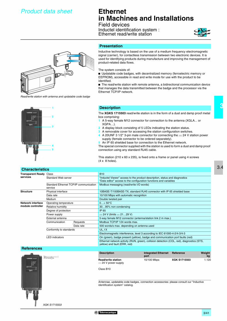
3/41
3
3.4
Product data sheet Ethernetin Machines and Installations 0
Field devicesInductel identification system :Ethernet read/write station
Inductive technology is based on the use of a medium frequency electromagnetic signal (carrier), for contactless transmission between two electronic devices. It is used for identifying products during manufacture and improving the management of product-related data flows.
The system consists of:b Updatable code badges, with decentralized memory (ferroelectric memory or EEPROM), accessible in read and write mode for use with the product to be identified.b The read/write station with remote antenna, a bidirectional communication device that manages the data transmitted between the badge and the processor via the Ethernet TCP/IP network.
The XGKS 1715503 read/write station is in the form of a dust and damp proof metal box comprising:1 A 5-way female M12 connector for connection to the antenna (XGLA... or
XGPA…).2 A display block consisting of 5 LEDs indicating the station status.3 A removable cover for accessing the station configuration switches.4 A 20UNF 3 1/2" 3-pin male connector for connecting the c 24 V station power
supply (female connector to be ordered separately).5 An IP 65 shielded base for connection to the Ethernet network. The special connector supplied with the station is used to form a dust and damp proof connection using any standard RJ45 cable.
This station (210 x 60 x 235), is fixed onto a frame or panel using 4 screws(4 x 8 holes).
Presentation
DATA DATA
DATA DATA
DATA DATA
DATA DATA
DATA DATA
DATA DATA
DATA DATA
DATA DATA
Read/write station with antenna and updatable code badge
1
2
3
45
Description
CharacteristicsTransparent Ready services
Class B10Standard Web server “Inductel Viewer” access to the product description, status and diagnostics
“Data editor” access to the configuration functions and variablesStandard Ethernet TCP/IP communication service
Modbus messaging (read/write I/O words)
Structure Physical interface 10BASE-T/100BASE-TX, standard RJ45 connector with IP 65 shielded base Data rate 10/100 Mbps with automatic recognition
Medium Double twisted pairNetwork interface module controller
Operating temperature 0…+ 50°CRelative humidity 30…95% non condensing
Degree of protection IP 65Power supply c 24 V (limits c 21…29 V)External antenna 5-way female M12 connector (antenna/station link 2 m max.)
Communication Requests Modbus TCP/IP 124 words max.Data rate 500 words/s max. depending on antenna used
Conformity to standards UL, eElectromagnetic interference, level 3 according to IEC 61000-4-2/4-3/4-3
LED indicators On (green), badge present (yellow), badge and communication port faults (red)Ethernet network activity (RUN, green), collision detection (COL, red), diagnostics (STS, yellow) and fault (ERR, red)
ReferencesDescription Integrated Ethernet
portReference Weight
kgRead/write stationc 24 V power supply
Class B10
10/100 Mbps XGK S1715503 1.120
Antennae, updatable code badges, connection accessories: please consult our “Inductive identification system” catalog.
XGK S1715503

3/42
3
3.4
Product data sheet Ethernetin Machines and Installations 0
Field devicesOsitrack identification system
RFID (Radio Frequency Identification) is a term generally used for radio frequency identification systems. These frequencies range between 50 kHz and 2.5 GHz. The most widely used is 13.56 MHz.The Ositrack RFID identification system enables object traceability, identification (tracking) functions to be performed and access control.
The information is stored in an accessible memory using a simple radio frequency link. This memoryis in the form of an electronic tag, which contains an antenna and an integrated circuit.The tag contains the information associated with the object to which it is fixed. When a tag passes through the field generated by the reader/station, it detects the signal and exchanges the data (read or write) between its memory and the reader/station.
Ositrack is open to the majority of ISO 18000-3, ISO 15693 and ISO 14443 electronic tags.Ositrack integrates Modbus RTU, Uni-Telway (1), Modbus TCP/IP and CANopen (1) protocols.
The Ethernet box XGS Z33ETH is fitted with M12 connectors. It is used to connect the supply, the Ethernet network and 1 to 3 stations XGC S.It comprises a sealed metal enclosure fitted with:1 Ethernet network signalling LEDs.2 One Ethernet M12 type, D coding, socket.3 One green LED indicator for connecting the 24 Vc power supply.4 One power supply M12 type 4-pinmale socket.5 3 x M12 type female, A coding, sockets for connecting 1 to 3 compact stations
XGC S.
Presentation
Description
1
2
4
5
3

3/43
3
3.4
Product data sheet (continued)
Ethernetin Machines and Installations 0
Field devicesOsitrack identification system
CharacteristicsTransparent Ready services
Class A10Standard Web server No Web server
Standard Ethernet TCP/IP communication service
Modbus messaging (read/write I/O words)
Structure Physical interface 10BASE-T/100BASE-T XData rate 10/100 Mbps with automatic recognitionMedium Ethernet cable with M12 connection (TCS ECL1M1pS2 : Telemecanique ConneXium range)
XGS cable connector
Operating temperature 0…+ 50°C
Relative humidity 30…95% non condensingDegree of protection IP 65Power supply c 24 V (limits c 19.2…29 V)
Connecting XGC S stations 5-way female M12 connectorCommunication Requests Modbus TCP/IP 124 words max.
Speed 2 Kbytes/s max. depending on associated tags
Conformity to standards UL, eElectromagnetic interference, level 3 according to IEC 61000 and EN 55022
LED indicators Ethernet network activity (RUN, green), collision detection (COL, red), diagnostics (STS, yellow), fault (ERR, red) and 24 Vc power supply (green)
ReferenceDescription Integrated Ethernet
portReference Weight
kgEthernet cable connector (for 3 XGC S compact stations)24 Vc power supply
Class A10
10/100 Mbps XGS Z33ETH 1.060
Stations, updatable code badges, connection accessories: please consult our “Inductive identification system” catalog.
(1) Available later for Uni-Telway and CANopen protocols.
XGS Z33ETH

3/44
3
3.5
Presentation Ethernetin Machines and Installations 0
Infrastructure
The ConneXium Industrial Ethernet Offer is comprised of a complete family of products and tools required to build the infrastructure of an Industrial Ethernet network. In the following chapter summary information for the proper design of a network and the selections of its components is offered.
There are three main areas of differentiation between Ethernet applications in an office environment and Ethernet applications in an Industrial environment, they are:b Environmentb Layout (not physical layer specification)b Performance
Contrary to the office environment and even though ISO/IEC is working on it, there are not yet clearly defined specifications for Ethernet devices targeted to Industrial applications. The specifications of what it is called Industrial Ethernet are defined by different agencies or entities based upon its nature and based upon what the automation market has traditionally used.
The environmental specifications of Industrial Ethernet devices are today defined by the traditional agencies that define the environmental specifications for standard industrial devices (UL, CSA, e, ...).
The IEEE 802.3 defines the physical layer specifications of the Ethernet network (types of connectors, distance between devices, number of devices, ...) while the 11801 (similarly to the TIAEIA 568B, and CENELEC EN 50173) provide installers the layout guidelines; therefore when designing and Industrial Ethernet network and selecting its infrastructure components the IEEE 802.3 rules for quantities of devices and lengths.
The performance specifications are actually being worked on by ISO/IEC.
The Ethernet 802.3 Link Layer is based on a collision detection mechanism (CSMA CD): every node whose information has collided on the network realizes the collision and re-sends the information.
The process of re-sending information causes delays in its propagation and could affect the application.A collision domain is a group of Ethernet end devices interconnected by hubs or repeaters (devices that receive information and send it out to all their other ports, no matter where the destination device is connected): it means that all devices will be affected by collisions.
With the availability of full duplex switches (devices that receive information and send it out just through the port to which the destination device is connected) the collision domains have disappeared.
Therefore, for industrial automation applications it is strongly recommended to use in every case full duplex switches to interconnect devices. In this way the collision domains will be eliminated completely.
Presentation
Office Ethernet versus Industrial Ethernet
Ethernet 802.3 principles
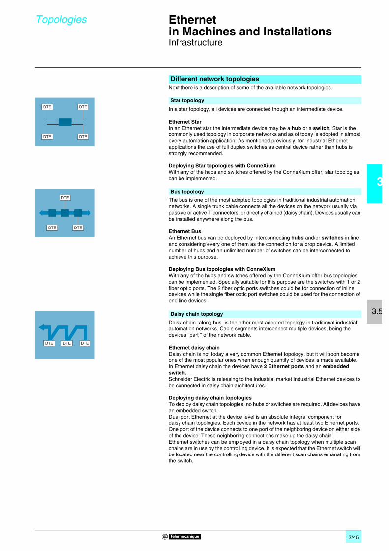
3/45
3
3.5
Topologies Ethernetin Machines and Installations 0
Infrastructure
Next there is a description of some of the available network topologies.
In a star topology, all devices are connected though an intermediate device.
Ethernet Star In an Ethernet star the intermediate device may be a hub or a switch. Star is the commonly used topology in corporate networks and as of today is adopted in almost every automation application. As mentioned previously, for industrial Ethernet applications the use of full duplex switches as central device rather than hubs is strongly recommended.
Deploying Star topologies with ConneXiumWith any of the hubs and switches offered by the ConneXium offer, star topologies can be implemented.
The bus is one of the most adopted topologies in traditional industrial automation networks. A single trunk cable connects all the devices on the network usually via passive or active T-connectors, or directly chained (daisy chain). Devices usually can be installed anywhere along the bus.
Ethernet BusAn Ethernet bus can be deployed by interconnecting hubs and/or switches in line and considering every one of them as the connection for a drop device. A limited number of hubs and an unlimited number of switches can be interconnected to achieve this purpose.
Deploying Bus topologies with ConneXiumWith any of the hubs and switches offered by the ConneXium offer bus topologies can be implemented. Specially suitable for this purpose are the switches with 1 or 2 fiber optic ports. The 2 fiber optic ports switches could be for connection of inline devices while the single fiber optic port switches could be used for the connection of end line devices.
Daisy chain -along bus- is the other most adopted topology in traditional industrial automation networks. Cable segments interconnect multiple devices, being the devices “part ” of the network cable.
Ethernet daisy chainDaisy chain is not today a very common Ethernet topology, but it will soon become one of the most popular ones when enough quantity of devices is made available. In Ethernet daisy chain the devices have 2 Ethernet ports and an embedded switch.Schneider Electric is releasing to the Industrial market Industrial Ethernet devices to be connected in daisy chain architectures.
Deploying daisy chain topologiesTo deploy daisy chain topologies, no hubs or switches are required. All devices have an embedded switch.Dual port Ethernet at the device level is an absolute integral component for daisy chain topologies. Each device in the network has at least two Ethernet ports. One port of the device connects to one port of the neighboring device on either side of the device. These neighboring connections make up the daisy chain. Ethernet switches can be employed in a daisy chain topology when multiple scan chains are in use by the controlling device. It is expected that the Ethernet switch will be located near the controlling device with the different scan chains emanating from the switch.
Different network topologies
Star topology
Bus topology
Daisy chain topology
DTE DTE
DTE DTE
DTE
DTEDTE
DTEDTE DTE

3/46
3
3.5
Topologies (continued), Ethernetin Machines and Installations 0
Infrastructure
Limitations of daisy chain:Limitations of daisy chain to insure the operational integrity of the network and meet performance metrics, are:b Dual port Ethernet devices only support 10 Mbit/s and/or 100 Mbit/s operational speeds and must use one or the other.b The network will operate only as fast as the slowest device that is connected to the networkb In order to improve network traffic latency the numbers of devices in a single scan chain, has been limited to 32 devices. b Limiting a single scan chain to 32 devices the time for a round trip of a packet through the daisy Chain is expected less than 5 milliseconds (with 32 devices plugged on a scan daisy chain.
The maximum packet latency of a packet passing through any device in a scan chain is no more than 10 µs.
The first Schneider Electric device with Ethernet daisy chain capabilities is the Lexium 15/17D servodrive, see pages 3/39 and 3/40.
In a ring topology, all devices or network infrastructure components are connected in a loop with no beginning or end. Through these types of topologies a type of network redundancy is achieved.
Ethernet RingEthernet rings are usually the backbones of applications in which high availability is required. If ring topology is required then switches that support this feature should be ordered.
Deploying Ring topologies using ConneXium.The ConneXium line offers hubs and switches that allow the deployment of single and coupled self-healing rings. There is additional information about this topic in the redundancy segment.
Daisy chain topology (continued)
Ring topology
DTEDTE
DTEDTE DTE DTE

3/47
3
3.5
Characteristics Ethernetin Machines and Installations 0
Infrastructure
(1) Based on 802.3, full duplex/half duplex.(2) Depends on the optical budget and fiber attenuation.(3) Depends on the optical fiber budget and fiber attenuation, typical specification is 2 km for
multimode and 15 km from monomode.
Nota : The above are the specifications defined by IEEE 802.3. However some of the cables are no longer being developed. For instance, for 10BASE-T and 100BASE-TX, a CAT-5e cable is used.
Distance limitations and number of devices per segmentBased upon the 802.3, the distance limits and the numbers of devices in cascade are the following:
Type Maximum segment length (1)
Maximum segment length (offered by ConneXium devices)
Maximum number of hubs in cascade
Maximum number of switches in cascade
10BASE-T 100 m 100 m 4 Unlimited
100BASE-TX 100 m 100 m 2 Unlimited1000BASE-T 100 m 100 m – Unlimited10BASE-FL 2000 m 3100 m (2) 11 (fiber ring) –
100BASE-FX 412 m/2000 m 4000 m with multimode, 32.500 m with monomode (3)
– Unlimited
1000BASE-SX 275 m – – Unlimited
Physical MediaThe Ethernet 802.3 defines the Physical Layer. A summary of the most common ones are shown belowType Data rate Cable type Connector type
Defined by 802.3 Recommended by Schneider Electric
Defined by 802.3 Recommended by Schneider Electric
10BASE-T 10 Mbit/s CAT 3 - UTP CAT 5E - STP RJ45 RJ45100BASE-TX 100 Mbit/s CAT 5 - UTP CAT 5E - STP RJ45 RJ45
1000BASE-T 1 Gbit/s CAT 5 - UTP CAT 5E - STP RJ45 RJ4510BASE-FL 10 Mbit/s Two multimode fiber optic
cables typically 62.5/125 µm fiber, 850 nm light wavelength
Two multimode fiber optic cables typically 62.5/125 µm fiber, 850 nm light wavelength
ST ST
100BASE-FX 100 Mbit/s Two multimode optical fibers typically 62.5/125 µm multimode fiber, 1300 nm light wavelength
Two multimode optical fibers typically 62.5/125 µm multimode fiber, 1300 nm light wavelength
ST SC
– Two monomode optical fibers typically 9/125 µm multimode fiber, 1300 nm light wavelength
– SC
1000BASE-SX 1 Gbit/s Two 62.5/125 or 50/125 multimode optical fibers, 770 to 860 nm light wavelength
Two 62.5/125 µm or 50/125 m multimode optical fibers , 1300 nm light wavelength
SC LC
1000BASE-LX 1 Gbit/s – Two 9/125 µm monomode optical fibers, 1300 nm light wavelength
– LC

3/48
3
3.5
Management Ethernetin Machines and Installations 0
Infrastructure
The Ethernet devices in general (end devices and the cabling devices) devices may be divided in two categories: unmanaged and managed devices:b The unmanaged devices are those which there is no possibility to configure or control any of the parameters of the device. b The managed devices are those which there is possibility to configure or control the parameters of the device (manage them) and to access to its internal information.
The ConneXium product line offers both types of devices.
There is also a third category of devices not specifically defined but is important to understand the difference. These devices only allow access to its information but can not be controlled and/or configured. Usually these devices are considered in the category of managed devices.
The managed devices offer the following features:b Traffic optimization and filtering, goal is to increase the bandwidth, or the traffic capacity in a network (some of the features in this area are message and port priority, flow control, multicast filtering, broadcast limiting, IGMP snooping, Vlan, etc.).b VLAN, a virtual LAN (VLAN) consists of a group of network participants in one or more network segments who can communicate with each other as if they belonged to the same LAN. VLANs are based on logical (instead of physical) links. The biggest advantage of VLANs is their possibility of forming user groups based on the participant function and not on their physical location or medium. Since broad/multicast data packets are transmitted exclusively within a virtual LAN, the remaining data network is unaffected. VLAN can also serve as a security mechanism to block unwanted Unicast messages.b Security, feature that helps the user protect the switch from unauthorized access that could result in changes in its configuration and impact the traffic going through the switch (some of the features in this area are port security, read/write community name, etc.). User can also set up the switch so that it blocks messages coming from unauthorized “devices” source addresses connected to the switch.b Time Synchronization, feature that allows all the devices in the network to be synchronized on time.b Network Redundancy, to develop high availability applications.b …
Management

3/49
3
3.5
Redundancy Ethernetin Machines and Installations 0
Infrastructure
To develop high availability applications, “redundancy” in the networking infrastructure is the answer. By implementing a single ring architecture, or a coupled ring one, can protect themselves against losses of network segments.
The first level of redundancy is achieved by implementing a single ring. The ConneXium switches allow the set up of backbone ring configurations.
The ring is constructed using the HIPER-Ring ports. If a section of the line fails, a ring structure of up to 50 Switches transforms back to a line-type configuration within 0.5 seconds.
The second level of redundancy is achieved by implementing a dual ring. The control intelligence built into the ConneXium switches allows the redundant coupling of HIPER-Rings and network segments.
These configurations would double the redundancy obtained by using a single ring.
A third level of redundancy can be achieved by implementing a mesh topology. In simple terms spaning tree is a protocol that ensures a single path for the signal, when multiple paths exist, and if the active path is broken, the spanning tree protocol enables one of the alternatives paths.
The ConneXium switches offer the possibility.
Redundancy
Single Ring
Dual Ring
Mesh topology using the Rapid Spanning Tree protocol
DTEDTE
DTEDTE DTE DTE
DTEDTE
DTEDTE DTE DTE
DTE
DTE
DTE DTE
DTE
DTE

3/50
3
3.5
Wiring system Ethernetin Machines and Installations 0
Infrastructure
The Schneider Electric Ethernet cable provides all cable options to wire IP20 and IP67 devices in copper as well as in fiber optic.
For key:1, 3: Straight cables, 2, 4: Crossed cord cables,8: Cables with IP 67 connector,see pages 3/52 and 3/53.
Presentation
ExamplesCombined IP20 and IP67 wiring, copper
1, 3
2, 4
2, 4
88
1, 3
1, 3
1, 3
1, 3 1, 3

3/51
3
3.5
Wiring system Ethernetin Machines and Installations 0
Infrastructure
For key:1, 3: Straight cables, 2, 4: Crossed cord cables,5, 6, 7: Fiber optic cables,8: Cables with IP 67 connector,
see pages 3/52 and 3/53.
Examples (continued)
Combined Copper and Fiber wiring
FirewallServer
1, 3 1, 3
1, 31, 3 1, 3 1, 3
1, 3
1, 3
1, 3
1, 3
1, 3
1, 31, 3
2, 4 2, 42, 4
2, 42, 4
2, 42, 4
2, 4
8
5, 6, 7
Preventa safety PLC
InternetMES Client
Router
Quantum
Quantum
Premium
TwidoAdvantys STB
Altivar 71
Altivar 71
Magelis
Magelis
Ositrack
FactoryCast gateway
ModbusManaged switch
Hub or unmanaged switch
Fiber link
Copper link
Copper link

3/52
3
3.5
Wiring system (continued) Ethernetin Machines and Installations 0
Ethernet TCP/IP, Transparent ReadyCabling system: Connexium connection components
ConneXium shielded connection cables are available in two versions to meet the various current standards and approvals:b EIA/TIA 568 standard shielded twisted pair cablesThese cables conform to: v EIA/TIA-568 standard, category CAT 5E, v IEC 11801/EN 50173 standard, class D. Their fire resistance conforms to: v NFC 32070# C2 classificationv IEC 322/1 standardsv Low Smoke Zero Halogen (LSZH).
b UL and CSA 22.1 approved shielded twisted pair cablesThese cables conform to: v UL and CSA 22.1 standardsTheir fire resistance conforms to NFPA 70.
These glass fiber optics are for making connections:b To a terminal device (DTE)b Between hubs, transceivers and switches
Shielded copper connection cables
490 NTp 000 pp
EIA/TIA 568 standard shielded twisted pair cablesDescription Preformed at both ends Rep. Length
m (ft)Reference Weight
kgStraight cables 2 RJ45 connectors
For connection to terminal devices (DTE)
1 2 (6.6) 490 NTW 000 02 –
5 (16.4) 490 NTW 000 05 –12 (39.4) 490 NTW 000 12 –40 (131.2) 490 NTW 000 40 –
80 (262.5) 490 NTW 000 80–
Crossed cord cables
2 RJ45 connectorsFor connections between hubs, switches and transceivers
2 5 (16.4) 490 NTC 000 05 –15 (49.2) 490 NTC 000 15 –40 (131.2) 490 NTC 000 40 –
80 (262.5) 490 NTC 000 80 –
UL and CSA 22.1 approved shielded twisted pair cablesDescription Preformed at both ends Rep Length Reference Weight
kgStraight cables 2 RJ45 connectors
For connection to terminal devices (DTE)
3 2 (6.6) 490 NTW 000 02U –5 (16.4) 490 NTW 000 05U –12 (39.4) 490 NTW 000 12U –
40 (131.2) 490 NTW 000 40U –80 (262.5) 490 NTW 000 80U –
Crossed cord cabless
2 RJ45 connectorsFor connections between hubs, switches and transceivers
4 5 (16.4) 490 NTC 000 05U –15 (49.2) 490 NTC 000 15U –
40 (131.2) 490 NTC 000 40U –80 (262.5) 490 NTC 000 80U –
Glass fiber optic cables
Description Preformed at both ends Rep. Length Reference Weightkg
Glass fiber optic cables
1 SC connector1 MT-RJ connector
5 5 (16.4) 490 NOC 000 05 –
1 ST connector (BFOC) 1 MT-RJ connector
6 5 (16.4) 490 NOT 000 05 –
2 MT-RJ connectors 7 3 (9.8) 490 NOR 000 03 –
5 (16.4) 490 NOR 000 05 –15 (49.2) 490 NOR 000 15 –
490 NOC 000 05
MT-RJ
SC
490 NOR 000 05
MT-RJ
MT-RJ
490 NOT 000 05
MT-RJ
ST

3/53
3
3.5
Wiring system (continued) Ethernetin Machines and Installations 0
Ethernet TCP/IP, Transparent ReadyCabling system: Connexium connection components
(1) Dimensions W x H X D = 20 x 18 x 50 mm.
Separate parts for TCS ESM switches
TCS EAA F1LFp 00
Description Optical fiber Type Reference Weightkg
Fiber optic modules for Gigabit ports with LC connector(1)
Multimode 50/125µm or 62.5/125µm
1000BASE-SX TCS EAA F1LFU00 0.040
Single mode 9/125µm 1000BASE-LH TCS EAA F1LFH00 0.040
Multimode 50/125µm or 62.5/125µmSingle mode 62.5/125µm
1000BASE-LX TCS EAA F1LFS00 0.040
Configuration backup key
Via the USB port on the front of the switch, used to: - save and retrieve the switch configuration- update the internal software
TCS EAM 0100 –
Connection components for IP 67 switchDescription Preformed at both
endsRep. Length
m (ft)Reference Weight
kgCopper cables 1 IP 67 4-way M12
connectorand 1 RJ45 connector
8 1 (3.3) TCS ECL 1M3M 1S2 –
1.5 (4.9) TCS ECL 1M3M 1X5S2 –3 (9,8) TCS ECL 1M3M 3S2 –5 (16.4) TCS ECL 1M3M 5S2 –
10 (32.8) TCS ECL 1M3M 10S2 –25 (82) TCS ECL 1M3M 25S2 –
40 (131.2) TCS ECL 1M3M 40S2 –
2 IP 67 4-way M12 connectors
– 1 (3.3) TCS ECL 1M1M 1S2 –1.5 (4.9) TCS ECL 1M1M 1X5S2 –3 (9,8) TCS ECL 1M1M 3S2 –
5 (16.4) TCS ECL 1M1M 5S2 –10 (32.8) TCS ECL 1M1M 10S2 –25 (82) TCS ECL 1M1M 25S2 –
40 (131.2) TCS ECL 1M1M 40S2 –
M12/RJ45 adaptor
IP 67 female 4-way M12 connector and female RJ45 connector
– – TCS EAA F11F13F00 –
Power cables Female M12 straight connector
– 2 (6.6) XZC P1164L2 –5 (16.4) XZC P1164L5 –
Female M12 elbowed connector
– 2.5 (8.2) XZC P1264L2 –
5 (16.4) XZC P1264L5 –
Power connectors
Female M12 straight connector
– – XZC C12 FDM 50B –
Female M12 elbowed connector
– – XZC C12 FCM 50B –

3/54
3
3.5
Ethernetin Machines and Installations 0
Ethernet TCP/IP, Transparent ReadyCabling system: ConneXium hub
Hubs (concentrators) are used for transmitting signals between several media (ports). Hubs are “plug and play” devices that do not need any configuration.The use of hubs makes it possible to create the following topologies:b Star topology using hubsb Tree topology using hubsConsult our catalogue “Ethernet TCP/IP and Web technologies, Transparent Ready”.
Presentation
DTE DTE
DTE DTE DTE DTE
Star topology Tree topology
Hub
Hub
HubHub
Characteristics and reference
HubsInterfaces Copper cable ports Number and type 4 x 10BASE-T ports
Shielded connectors RJ45Medium Shielded twisted pair, category CAT 5E
Total length of pair 100 mFiber optic ports Number and type –
Topology Number of cascaded hubs max. 4Number of hubs in a ring –
Redundancy P1 and P2 redundant power supplies
Power supply Voltage 24 V (18…32) c, safety extra low voltage (SELV)
Power consumption 80 mA (130 max. at 24 V c)Removable connector 5-way
Operating temperature 0…+ 60 °CRelative humidity 10…95% non condensing
Degree of protection IP 30Dimensions W x H x D 40 x 125 x 80 mmMounting On symmetrical DIN rail, 35 mm wide
Weight 0.530 kg
Conformity to standards cUL 60950, UL 508 and CSA 142, UL 1604 and CSA 213 Class 1 Division 2, e, GLFM 3810, FM 3611 Class 1 Division 2
LED indicators Power supply, activity, link
Alarm relay Power supply fault, Ethernet network fault or communication port fault (1 A max. volt-free contact at 24 V c)
Reference 499 NEH 104 10
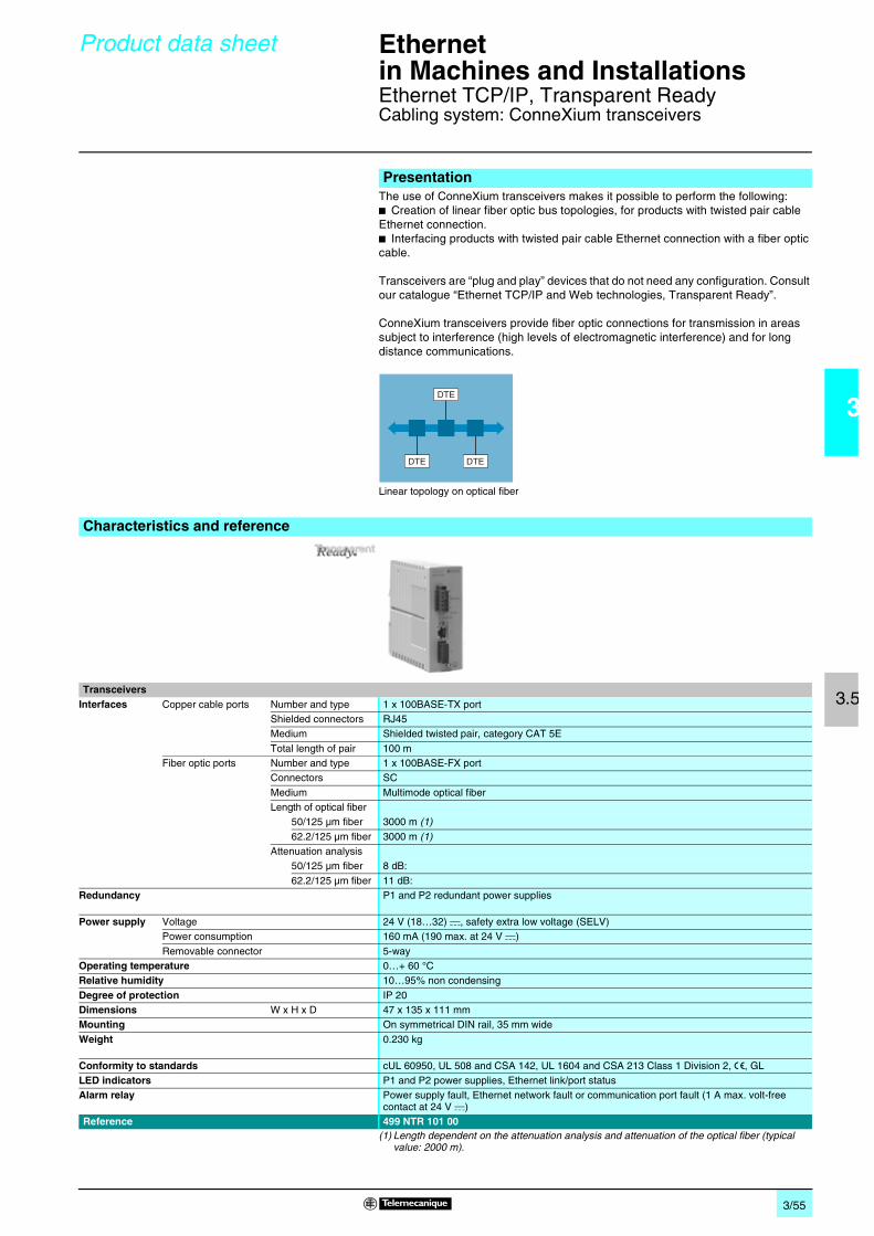
3/55
3
3.5
Product data sheet Ethernetin Machines and Installations 0
Ethernet TCP/IP, Transparent ReadyCabling system: ConneXium transceivers
The use of ConneXium transceivers makes it possible to perform the following: b Creation of linear fiber optic bus topologies, for products with twisted pair cable Ethernet connection.b Interfacing products with twisted pair cable Ethernet connection with a fiber optic cable.
Transceivers are “plug and play” devices that do not need any configuration. Consult our catalogue “Ethernet TCP/IP and Web technologies, Transparent Ready”.
ConneXium transceivers provide fiber optic connections for transmission in areas subject to interference (high levels of electromagnetic interference) and for long distance communications.
(1) Length dependent on the attenuation analysis and attenuation of the optical fiber (typical value: 2000 m).
Presentation
DTE
DTEDTE
Linear topology on optical fiber
Characteristics and reference
TransceiversInterfaces Copper cable ports Number and type 1 x 100BASE-TX port
Shielded connectors RJ45Medium Shielded twisted pair, category CAT 5E
Total length of pair 100 mFiber optic ports Number and type 1 x 100BASE-FX port
Connectors SC
Medium Multimode optical fiberLength of optical fiber
50/125 µm fiber 3000 m (1)
62.2/125 µm fiber 3000 m (1)Attenuation analysis
50/125 µm fiber 8 dB:
62.2/125 µm fiber 11 dB:Redundancy P1 and P2 redundant power supplies
Power supply Voltage 24 V (18…32) c, safety extra low voltage (SELV)Power consumption 160 mA (190 max. at 24 V c)
Removable connector 5-wayOperating temperature 0…+ 60 °CRelative humidity 10…95% non condensing
Degree of protection IP 20Dimensions W x H x D 47 x 135 x 111 mmMounting On symmetrical DIN rail, 35 mm wide
Weight 0.230 kg
Conformity to standards cUL 60950, UL 508 and CSA 142, UL 1604 and CSA 213 Class 1 Division 2, e, GLLED indicators P1 and P2 power supplies, Ethernet link/port statusAlarm relay Power supply fault, Ethernet network fault or communication port fault (1 A max. volt-free
contact at 24 V c)Reference 499 NTR 101 00

3/56
3
3.5
Product data sheet Ethernetin Machines and Installations 0
Ethernet TCP/IP, Transparent ReadyCabling system: ConneXium unmanaged switches
PresentationSwitches are used to increase the limits of architectures based on hubs or transceivers, by separating collision domains. Higher layer communication is provided between the ports, and collisions at link layer are not propagated (filtering). They therefore improve performance by better allocation of the pass band due to the reduction of collisions and the network load.Certain Connexium switch models also enable redundant architectures to be created on twisted pair copper ring or fiber optic.
Switches are “plug & play” devices that do not need any configuration. They can also be managed remotely via the SNMP or HTTP protocols for monitoring and diagnostics purposes.
Characteristics and references: twisted pair
Switches Optimized, copper twisted pair, unmanaged
Copper twisted pair, unmanaged
Interfaces Copper cable ports Number and type 5 x 10BASE-T/100BASE-TX ports 8 10BASE-T/100BASE-TX portsShielded connectors RJ45
Medium Shielded twisted pair, category CAT 5ETotal length of pair 100 m
Fiber optic ports Number and type –
Connectors –Medium –Length of optical fiber
50/125 µm fiber –62.2/125 µm fiber9/125 µm fiber –
Attenuation analysis50/125 µm fiber –62.2/125 µm fiber
9/125 µm fiber –Topology Number of switches Cascaded Unlimited
Redundant in a ring –
Redundancy – P1 and P2 redundant power supplies
Power supply Voltage 24 V c (19.2…30) 24 V c (18…32) safety extra low voltage (SELV)Power consumption mA max. 120 125 (290 max.)Removable connector 3-way 5-way
Operating temperature 0…+ 60 °CRelative humidity 10…95% non condensingDegree of protection IP 20
Dimensions W x H x D 75.2 x 143 x 43 mm 47 x 135 x 111 mmMounting On symmetrical DIN rail, 35 mm wideWeight 0.190 kg 0.230 kg
Conformity to standards UL 508, CSA 1010, EN 61131-2 cUL 60950, UL 508 and CSA 142, UL 1604 and CSA 213 Class 1 Division 2, e, GL
LED indicators Power supply, link status, data rate P1 and P2 power supplies, Ethernet link/port status
Alarm relay – Power supply fault, Ethernet network fault or communication port fault (1 A max. volt-free contact at 24 V c)
Reference 499 NES 251 00 499 NES 181 00
DTE
DTEDTE
DTE DTE
DTE DTE
DTE DTE
DTE
DTEDTE
DTE DTE
DTE
DTEDTE
DTE DTE
DTE DTE
100 Mbps optical ring
Collision domain 1
Collision domain 2
Collision domain 3

3/57
3
3.5
Product data sheet (continued)
Ethernetin Machines and Installations 0
Ethernet TCP/IP, Transparent ReadyCabling system: ConneXium unmanaged switches
Characteristics and references: 5 ports, twisted pair and fiber optic
Switches Copper twisted pair and fiber optic, unmanaged
Interfaces Copper cable ports Number and type 4 x 10BASE-T/100BASE-TX ports
3 x 10BASE-T/100BASE-TX ports
4 x 10BASE-T/100BASE-TX ports
3 x 10BASE-T/100BASE-TX ports
Shielded connectors RJ45Medium Shielded twisted pair, category CAT 5E
Total length of pair 100 mFiber optic ports Number and type 1 x 100BASE-FX port 2 x 100BASE-FX ports 1 x 100BASE-FX port 2 x 100BASE-FX ports
Connectors SC
Medium Multimode optical fiber Single mode optical fiberLength of optical fiber
50/125 µm fiber 5,000 m (1) –
62.2/125 µm fiber 4,000 m (1) –9/125 µm fiber – 32,500 m (2)
Attenuation analysis
50/125 µm fiber 8 dB –62.2/125 µm fiber 11 dB –9/125 µm fiber – 16 dB
Topology Number of switches Cascaded UnlimitedRedundant in a ring –
Redundancy P1 and P2 redundant power supplies
Power supply Voltage 24 V c (18…32), safety extra low voltage (SELV)
Power consumption mA max. 200 240 200 240Removable connector 5-way
Operating temperature -40...+70 °C
Relative humidity 10…95% non condensingDegree of protection IP 20Dimensions W x H x D 47 x 135 x 111 mm
Mounting On symmetrical DIN rail, 35 mm wideWeight 0.330 kg 0.335 kg 0.330 kg 0.335 kg
Conformity to standards cUL 60950, cUL 508 and CSA 142, UL 1604 and CSA 213 Class 1 Division 2, e, GLLED indicators P1 and P2 power supplies, Ethernet link status, transmission activity
Alarm relay Activity, power supply fault, Ethernet network fault or communication port fault (1 A max. volt-free contact at 24 V c)
Reference 499 NMS 251 01 499 NMS 251 02 499 NSS 251 01 499 NSS 251 02(1) Length dependent on the attenuation analysis and attenuation of the fiber optic (typical
value: 2,000 m).(2) Length dependent on the attenuation analysis and attenuation of the fiber optic (typical
value: 15,000 m).

3/58
3
3.5
Product data sheet Ethernetin Machines and Installations 0
Ethernet TCP/IP, Transparent ReadyCabling system: ConneXium managed switches
(1) Length dependent on the attenuation analysis and attenuation of the fiber optic (typical value: 2,000 m).
(2) Length dependent on the attenuation analysis and attenuation of the fiber optic (typical value: 15,000 m).
Characteristics and references: 4 ports, twisted pair and fiber optic
Switches Copper twisted pair and fiber optic, managed
Interfaces Copper cable ports Number and type 3 x 10/100BASE-TX ports
2 x 10/100BASE-TX ports
3 x 10/100BASE-TX ports
2 x 10/100BASE-TX ports
Shielded connectors RJ45Medium Shielded twisted pair, category CAT 5ETotal length of pair 100 m
Fiber optic ports Number and type 1 x 100BASE-FX port 2 x 100BASE-FX ports 1 x 100BASE-FX port 2 x 100BASE-FX portsConnectors Duplex SCMedium Multimode optical fiber Single mode optical fiber
Length of optical fiber50/125 µm fiber 5,000 m (1) –
62.2/125 µm fiber 4,000 m (1) – 9/125 µm fiber – 32,500 m (2)
Attenuation analysis
50/125 µm fiber 8 dB –62.2/125 µm fiber 11 dB –9/125 µm fiber – 16 db
Ethernet services FDR, SMTP V3, SNTP client, multicast filtering for optimization of the Global Data protocol, configuration via Web accessVLAN, IGMP Snooping, RSTP (Rapid Scanning Tree Protocol), priority port, data stream control, secure port
Topology Number of switches Cascaded UnlimitedRedundant in a ring max. 50
Redundancy Redundant power supplies, redundant single ring, ring coupling
Power supply Voltage Operation 9.6...60 V c/18…30 V a, safety extra low voltage (SELV)Power consumption 6.5 W 7.3 W 6.5 W 7.3 WRemovable connector 6-way
Operating temperature 0…+ 60 °CRelative humidity 10…90% non condensingDegree of protection IP 20
Dimensions W x H x D 47 x 131 x 111 mmMounting On symmetrical DIN rail, 35 mm wideWeight 0.400 kg
Conformity to standards IEC 61131-2, IEC 61850-3, UL 508, UL 1604 Class 1 Division 2, CSA C22.2 14 (cUL), CSA C22.2 213 Class 1 Division 2 (cUL), e, GL
LED indicators Power supply status, alarm relay status, active redundancy, redundancy management, copper port status and copper port activity
Alarm relay Power supply fault, Ethernet network fault, communication port fault, redundancy fault (1 A max. volt-free contact at 24 V c)
Reference TCS ESM043F1CU0
TCS ESM043F2CU0
TCS ESM043F1CS0
TCS ESM043F2CS0

3/59
3
3.5
Product data sheet (continued)
Ethernetin Machines and Installations 0
Ethernet TCP/IP, Transparent ReadyCabling system: ConneXium managed switches
Characteristics and references: 4 and 8 ports, twisted pair
Switches Copper twisted pair, managed
Interfaces Copper cable ports Number and type 4 x 10/100BASE-TX ports 8 x 10/100BASE-TX ports
Shielded connectors RJ45Medium Shielded twisted pair, category CAT 5E
Total length of pair 100 mFiber optic ports Number and type –
Connectors –
MediumLength of optical fiber
50/125 µm fiber –
62.2/125 µm fiber –9/125 µm fiber –
Attenuation analysis
50/125 µm fiber –62.2/125 µm fiber –9/125 µm fiber –
Ethernet services FDR, SMTP V3, SNTP client, multicast filtering for optimization of the Global Data protocol, configuration via Web accessVLAN, IGMP Snooping, RSTP (Rapid Scanning Tree Protocol), priority port, data stream control, secure port
Topology Number of switches Cascaded UnlimitedRedundant in a ring max. 50
Redundancy Redundant power supplies, redundant single ring, ring coupling
Power supply Voltage Operation 9.6...60 V c/18…30 V a, safety extra low voltage (SELV)Power consumption 5.3 W 5.3 WRemovable connector 6-way
Operating temperature 0…+ 60 °CRelative humidity 10…90% non condensingDegree of protection IP 20
Dimensions W x H x D 47 x 131 x 111 mm 74 x 131 x 111 mmMounting On symmetrical DIN rail, 35 mm wideWeight 0.400 kg
0.410 kg
Conformity to standards IEC 61131-2, IEC 61850-3, UL 508, UL 1604 Class 1 Division 2, CSA C22.2 14 (cUL), CSA C22.2 213 Class 1 Division 2 (cUL), e, GL
LED indicators Power supply status, alarm relay status, active redundancy, redundancy management, copper port status and copper port activity
Power supply status, alarm relay status, active redundancy, redundancy management, fiber port status and fiber port activity
Alarm relay Power supply fault, Ethernet network fault or communication port fault (1 A max. volt-free contact at 24 V c)
Reference TCS ESM 043F23F0 TCS ESM 083F23F0

3/60
3
3.5
Product data sheet (continued)
Ethernetin Machines and Installations 0
Ethernet TCP/IP, Transparent ReadyCabling system: ConneXium managed switches
(1) Length dependent on the attenuation analysis and attenuation of the fiber optic (typical value: 2,000 m).
(2) Length dependent on the attenuation analysis and attenuation of the fiber optic (typical value: 15,000 m).
Characteristics and references: 8 ports, twisted pair and fiber optic
Switches Copper twisted pair and fiber optic, managed
Interfaces Copper cable ports Number and type 7 x 10/100BASE-TX ports
6 x 10/100BASE-TX ports
7 x 10/100BASE-TX ports
6 x 10/100BASE-T ports
Shielded connectors RJ45Medium Shielded twisted pair, category CAT 5ETotal length of pair 100 m
Fiber optic ports Number and type 1 x 100BASE-FX port
2 x 100BASE-FX ports
1 x 100BASE-FX port
2x 100BASE-FX ports
1 + 1 x 100BASE-FX port
Connectors Duplex SC
Medium Multimode optical fiber Single mode optical fiber Single mode optical fiber and multimode optical fiber
Length of optical fiber50/125 µm fiber 5,000 m (1) – 5,000 m (1)
62.2/125 µm fiber 4,000 m (1) – 4,000 m (1)9/125 µm fiber – 32,500 m (2) 32,500 m (2)
Attenuation analysis
50/125 µm fiber 8 dB – 8 dB62.2/125 µm fiber 11 dB – 11 dB9/125 µm fiber – 16 dB 16 dB
Ethernet services FDR, SMTP V3, SNTP client, multicast filtering for optimization of the Global Data protocol, configuration via Web accessVLAN, IGMP Snooping, RSTP (Rapid Scanning Tree Protocol), priority port, data stream control, secure port
Topology Number of switches Cascaded UnlimitedRedundant in a ring max. 50
Redundancy Redundant power supplies, redundant single ring, ring coupling
Power supply Voltage Operation 9.6...60 V c/18…30 V a, safety extra low voltage (SELV)Power consumption 6.5 W 7.3 W 6.5 W 7.3 WRemovable connector 6-way
Operating temperature 0…+ 60 °CRelative humidity 10… 90% non condensingDegree of protection IP 20
Dimensions W x H x D 74 x 131 x 111 mmMounting On symmetrical DIN rail, 35 mm wideWeight 0.410 kg
Conformity to standards IEC 61131-2, IEC 61850-3, UL 508, UL 1604 Class 1 Division 2, CSA C22.2 14 (cUL),
CSA C22.2 213 Class 1 Division 2 (cUL), e, GLLED indicators Power supply status, alarm relay status, active redundancy, redundancy management,
fiber port status and fiber port activityAlarm relay Power supply fault, Ethernet network fault or communication port fault (1 A max. volt-free
contact at 24 V c)Reference TCSESM
083F1CU0TCSESM083F2CU0
TCSESM 083F1CS0
TCSESM083F2CS0
TCSESM083F2CX0

3/61
3
3.5
Product data sheet (continued)
Ethernetin Machines and Installations 0
Ethernet TCP/IP, Transparent ReadyCabling system: ConneXium managed switches
(1) Length dependent on the attenuation analysis and attenuation of the fiber optic (typical value: 2,000 m).
Characteristics and references: 16 and 24 ports, twisted pair, fiber optic
Switches Copper twisted pair and fiber optic, managed
Copper twisted pair, managed
Copper twisted pair and fiber optic, managed
Interfaces Copper cable ports Number and type 16 x 10/100BASE-TX ports 14 x 10/100BASE-TX ports 22 x 10/100BASE-TX ports
Shielded connectors RJ45Medium Shielded twisted pair, category CAT 5ETotal length of pair 100 m
Fiber optic ports Number and type – 2 x 100BASE-FX portsConnectors – Duplex SCMedium – Multimode optical fiber
Length of optical fiber50/125 µm fiber – 5,000 m (1)62.2/125 µm fiber – 4,000 m (1)
9/125 µm fiber – –Attenuation analysis
50/125 µm fiber – 8 dB
62.2/125 µm fiber – 11 dB9/125 µm fiber – –
Ethernet services FDR, SMTP V3, SNTP client, multicast filtering for optimization of the Global Data protocol, configuration via Web accessVLAN, IGMP Snooping, RSTP (Rapid Scanning Tree Protocol), priority port, data stream control, secure port
Topology Number of switches Cascaded UnlimitedRedundant in a ring max. 50
Redundancy Redundant power supplies, redundant single ring, ring coupling
Power supply Voltage Operation 9.6...60 V c/18…30 V a, safety extra low voltage (SELV)
Power consumption 9.4 W 11.8 W 15.5 WRemovable connector 6-way
Operating temperature 0…+ 60 °C
Relative humidity 10… 90% non condensingDegree of protection IP 20Dimensions W x H x D 111 x 131 x 111 mm
Mounting On symmetrical DIN rail, 35 mm wideWeight 0.600 kg 0.650 kg
Conformity to standards cUL 60950, UL 508 and CSA 142, UL 1604 and CSA 213 Class 1 Division 2, e, GLLED indicators Redundant power supplies,
single ringRedundant power supplies, single ring, double ring
Alarm relay Power supply fault, Ethernet network fault or communication port fault (1 A max. volt-free contact at 24 V c)
Reference TCSESM 163F2CU0 TCSESM 163F23F0 TCSESM 243F2CU0

3/62
3
3.5
Product data sheet (continued)
Ethernetin Machines and Installations 0
Ethernet TCP/IP, Transparent ReadyCabling system: ConneXium managed switches
(1) With TCS EAA F1LFU00 fiber optic module to be ordered separately, see page 3/53.(2) With TCS EAA F1LFH00 fiber optic module to be ordered separately, see page 3/53.(3) With TCS EAA F1LFS00 fiber optic module to be ordered separately, see page 3/53.
Characteristics and references: 8 ports and 2 Gigabit ports, twiwted pair, fiber optic
Switches Copper twisted pair and fiber optic, managed Copper twisted pair, managedInterfaces Copper cable ports Number and type 8 x 10/100BASE-TX ports 8 x 10/100BASE-TX ports and
2 x 10/100/1000BASE-TX ports (Gigabit)
Shielded connectors RJ45Medium Shielded twisted pair, category CAT 5ETotal length of pair 100 m
Gigabit portsfiber optic (with SFP fiber module to be mounted on SFP connector)
Number and type 2 x 1000BASE-SX ports (1)
2 x 1000BASE-LH ports (2)
2 x 1000BASE-LX ports (3)
–
Connectors LC –
Medium Multimode optical fiber
Single mode optical fiber
Single mode and multimode optical fiber
–
Length of optical fiber
50/125 µm fiber 550 m – 550 m –62.2/125 µm fiber 275 m – 550 m –9/125 µm fiber – 8 -72,000 m 20,000 m –
Attenuation analysis50/125 µm fiber 7.5 dB – 11 dB –62.2/125 µm fiber 7.5 dB – 11 dB –
9/125 µm fiber – 6 - 22 dB 11 dB –Ethernet services FDR, SMTP V3, SNTP client, multicast filtering for optimization of the Global Data protocol,
configuration via Web accessVLAN, IGMP Snooping, RSTP (Rapid Scanning Tree Protocol), priority port, data stream control, secure port
Topology Number of switches Cascaded Unlimited
Redundant in a ring max. 50Redundancy Redundant power supplies, redundant single ring, ring coupling
Power supply Voltage Operation 9.6...60 V c/18…30 V a, safety extra low voltage (SELV)Power consumption 8.9 W + 1 W per SFP fiber module 8.3 W
Removable connector 6-wayOperating temperature 0…+ 60 °CRelative humidity 10… 90% non condensing
Degree of protection IP 20Dimensions W x H x D 111 x 131 x 111 mmMounting On symmetrical DIN rail, 35 mm wide
Weight 0.410 kg
Conformity to standards cUL 60950, UL 508 and CSA 142, UL 1604 and CSA 213 Class 1 Division 2, e, GLLED indicators Power supply status, alarm relay status, active redundancy, redundancy management,
fiber port status and fiber port activityAlarm relay Power supply fault, Ethernet network fault or communication port fault (1 A max. volt-free
contact at 24 V c)
Reference TCS ESM 103F2LG0 TCS ESM 103F23G0

3/63
3
3.5
Product data sheet Ethernetin Machines and Installations 0
Ethernet TCP/IP, Transparent ReadyCabling system: ConneXium IP 67 switch
Characteristics and references: IP 67 unmanaged switch
IP 67 switch Twisted pair, unmanagedInterfaces Copper cable ports Number and type 5 x 10BASE-T/100BASE-TX ports
Shielded connectors M12 (type D) Medium Shielded twisted pair, category CAT 5ETotal length of pair 100 m
Fiber optic ports Number and type –Connectors –Medium –
Length of optical fiber –Attenuation analysis –
Ethernet services Storage and re-routing of received data, auto MDI/MDX (automatic switching depending on whether cables are straight or crossed), automatic negotiation of 10/100 Mbps and duplex mode (on all ports), automatic change of polarity
Topology Number of switches Cascaded UnlimitedRedundant in a ring –
Redundancy –Power supply Voltage 24 V c (18…32 V c), safety extra low voltage (SELV)
Power consumption 100 mA
Connector 5-way M12 (type A, male)Operating temperature 0…+ 60°CRelative humidity –
Degree of protection IP 67Dimensions W x H x D 60 x 126 x 31 mmWeight 0.210 kg
Conformity to standards cUL 508 and CSA 22.2 14LED indicators Power supply, line status, line activityAlarm relay –
Reference TCS ESU 051 F0
IP 67 cordsetsEthernet cordsets Preformed at each end, see page 3/53
Power supply cables Preformed at each end with M12 female straight connectors
Preformed at each end with female M12 angled connectors
Length 2 m 5 m 2.5 m 5 m
Reference XZC P1164L2 XZC P1164L5 XZC P1264L2 XZC P1264L5
Spare power connectors Female M12 straight connector Female M12 angled connectorReference XZC C12 FDM 50B XZC C12 FCM 50B

3/64
3
3.6
Product data sheet Ethernetin Machines and Installations 0
Ethernet gatewaysEthernet/Modbus gateway
TSX ETG 100 gateway provides a simple and low-cost means of integrating any existing Modbus serial RTU device, installation or automation island in an Ethernet TCP/IP network infrastructure.The gateway is able to make the serial Modbus devices directly accessible to high level application in real time (management, SCADA).
Modbus serial devices can be Twido controller, Compact/Momentum/ Premium/Quantum PLCs, Altivar variable speed drives, Altistart starters, Magelis terminals or any other products compatible withe the Modbus standards.
TSX ETG 100 gateway is an IP 30 box, mounted on DIN rail.1 A screw terminal for connecting the c 24 V power supply.2 A standard RJ45 connector for 10BASE-T/100BASE-TX interface.3 Seven LED indicators for Ethernet communication (LK, RX, TX, 100), and serial
link communication (RS485, RX, TX).4 A LED indicator for c 24 V power supply and Reset button.5 A RJ45 connector for Modbus RS 232 sérial link.6 A micro switches for 2 or 4-wire RS 485 serial link configuration.7 A 5-way removable terminal block for Modbus RS 485 serial link .
Presentation
Description
1
2
5
6
7
3
4
CharacteristicsType of gateway TSX ETG 100
Transparent Ready services
Class B10Standard Web services
Configuration Predefined Web pagesRead/Write Acces to connected products list, reading of Modbus devices registers
Diagnostic Via predefined Web pages : diagnostic on Ethernet and Modbus linksEthernet TCP/IP communication management services
Modbus messaging Read/Write Modbus registers of connected devices
SNMP SNMP Agent, device administration with a SNMP managerBOOTP protocol FDR Client (replacement of defective product)Security Miniature firewall on-board (IP address filtering) and password protection
Ethernet connectivity
Physical interface 10BASE-T/100BASE-TX (RJ45)Data rate 10/100 Mbps with automatic recognitionMedium Twisted pair
Modbus connectivity Type of port RS 485 (2 or 4-wire) or RS 232Protocol Modbus (RTU and ASCII)Maxi transmission speed 38,4 Kbps (RS 485), 57,6 Kbps (RS 232)
Number of devices 32 max.Other characteristics Operating temperature 0...+ 60 °C
Relative humidity 5…95% non condensing at 40 °C
Degree of protection IP 30Dimensions (L x H x P) 72 x 81 x 76 mm, mounting on symmetrical DIN railPower supply c 24 V, 4 W or by power supply device PoE (Power Over Ethernet - IEEE 802.3af)
Conformity to standards UL, cUL (conforming to CSA C22-2 no. 14-M91), UL508, eEnvironmental resistance EN 61000-6-2, EN 61000-4-2/3/4/5/6/8, EN 55022/FCC class A
ReferencesDescription Fonctions References Weight
kgModbus Ethernet gateway/router
Class B 10
Twido, Compact, Momentum, TSX Micro, Altivar, Altistart, Magelis, ... All products compatible with Modbus standard
TSX ETG 100 –
Kit for configuration Allows gateway configuration through Ethernet or RS 232 port. Comprises RJ45/9-way SUB-D adaptator and a CAT5 twisted pair cable, 3 m length
TCS EAK 0100 –
PoE power supply (conform to IEEE 802.3af)
Allows gateway power supply through Ethernet CAT5 cable. Daisy chain power supply connection. Include power supply cable (Australia, Europa, UK and USA)
TCS EAQ 0100 –TSX ETG 100 TCS EAQ 0100

3/65
3
3.6
Product data sheet Ethernetin Machines and Installations 0
Ethernet gatewaysWeb FactoryCast Gateway
FactoryCast Gateway is a new offer of “all in one” intelligent Web gateways integrating, in a standalone compact unit:b All the TCP/IP network communication and serial link (Modbus or Uni-Telway) interfaces.b An RAS remote access (1)/IP Router function.b A customizable Web server .TSX ETG 1000/1010 gateways are a low-cost response to the need to integrate serial link installations in an existing Ethernet TCP/IP infrastructure as well as requirements for remote access services including remote diagnostics, remote maintenance, remote monitoring and remote control.
TSX ETG 1000/1010 FactoryCast Gateways feature, on the front panel:1 Three LEDs indicating the gateway status (RUN, ERR, Ethernet)2 The module MAC address (default factory-set address)3 A mini-DIN connector for connection to the terminal port (marked TER)4 An RJ45 connector for the serial link (Modbus or Uni-Telway) (marked RS 485)5 A standard RJ45 connector for connection to the Ethernet TCP/IP network
(marked ETHERNET)6 A 9-way male SUB-D connector for the RS 232 serial link (marked
Modem RS 232)7 A screw terminal for connecting the 24 Vc external power supply8 A support plate for fixing the module to a DIN rail or an AM1-PA pre-slotted plate
Presentation
Description 1
4
5
6
7
8
23
TSX ETG 1000 TSX ETG 1010
CharacteristicsWeb gateway module FactoryCast Gateway TSX ETG 1000 TSX ETG 1010
Transparent Ready servicesClass C20
Gateway/router function Ethernet TCP/IP gateway to Modbus, modem to Modbus and modem to Ethernet TCP/IP with IP routing
Ethernet TCP/IP gateway to Uni-Telway, modem to Uni-Telway and modem to Ethernet TCP/IP with IP routing
Routing of the I/O Scanning serviceProtocols Serial Modbus master Uni-Telway slave
TCP/IP Modbus TCP/IP Uni-TE TCP and/or Modbus TCP/IPStandard Web services
Configuration Via predefined Web pagesDiagnostic Via predefined Web pages: Diagnostics on Ethernet link, serial link, modem link; and
diagnostics on e-mail and FDR servicesRead/write Data editor, “ready-to-use” Web pages: Access to connected device registers
Configurable Web services HTTP server (8 MB of Flash memory available)Hosting of animated Web pages created by the user and all documents (doc, pdf, etc.)Library of graphic objects (Java applet) with Wizard utility for FrontPage
File upload/download via FTPE-mail service Alarm notification by e-mail (via remote SMTP server)Ethernet TCP/IP advanced communication services
BootP/DHCP protocol Automatic assignment of IP address, FDR client (replacement of defective product)
SNMP SNMP agent, administration of the device by an SNMP managerSecurity Miniature firewall on-board (IP address filtering) and password protection
Connectivity Ethernet TCP/IP Physical interface RJ45 standard 10BASE-T/100BASE-TX connectorData rate 10/100 Mbps with automatic recognitionMedium Twisted pairs
Modem Physical interface RS 232C link, half- or full-duplex, 57 kbps, 9-way SUB-D connectorPPP protocol (incoming and outgoing calls), PAP authentication protocol
Services Remote access via RAS compatible with RTC, GSM, VPN modemSerial link Physical interface Modbus RS 485 link, max. 115 kbps, standard
RJ45 connectorUni-Telway RS 485 link, max. 19.2 kbps, standard RJ45 connector
No. of devices 32 max.Characteristics Operating temperature 0 to + 60°C
Relative humidity 10 to 95% non condensing during operationDegree of protection IP 20Power supply c 24 V (limits c 19.2 to 30 V), 100 mA
Conformity to standards ISO/IEC 8802-3, ANSI/IEEE Std 802.3, EN 61000-6-4, EN 55011 Class A,IEC/EN 61131-2, UL 508, CSA C22.2 No. 142, CSA C22.2 No. 213 Class 1 Division 2
Pending: Marine Marchande certifications LED indicators Modbus activity (RUN Modbus) Uni-Telway activity (RUN/UTW)
Ethernet activity (ETHERNET), gateway error (ERR)
References Designation Routing Reference Weight
kgWeb FactoryCast Gateway gateways/routersClass C20
Ethernet / Modbus RTU TSX ETG 1000 0,280Ethernet / Uni-Telway TSX ETG 1010 0,280
TSX ETG 1000 TSX ETG 1010

3/66
3
3.6
Product data sheet Ethernetin Machines and Installations 0
Ethernet gatewaysEthernet/Modbus Plus gateway/router
The 174 CEV ConneXium communication gateways are used for interconnecting the following:b Modbus/Ethernet TCP/IP for 174 CEV 300 20b Modbus Plus/Ethernet TCP/IP for 174 CEV 200 40 by providing multiple ports to adapt to the different architecture.
Presentation
Characteristics
Type of gateway 174 CEV 200 40Transparent Ready services
Class B10Standard Web services Configuration Predefined Web pages
Read/Write Acces to connected products list, reading of Modbus Plus devices registers Diagnostic Via predefined Web pages : diagnostic on Ethernet and Modbus Plus links
Standard Ethernet TCP/IP communication services
Modbus TCP messagingSNMP Agent
Functions Communication gateway Ethernet/Modbus Plus (many-to-many Modbus Plus)
Interface for programming Ethernet/Modbus PlusModbus SL (RS 232/RS 485 serial link) –Modbus Plus (RS 485 network) Token bus, HDLC synchronous mode
Data rate 1 MbpsConfiguration Local or remote (1)
Interfaces Ethernet TCP/IP port Type 1 x 10BASE-T/100BASE-TXShielded connectors RJ45 Medium Shielded twisted pair
Max. distances 100 m (327 ft)Serial port Type 1 x Modbus Plus
Shielded connectors 9-way SUB-D connector
Medium Shielded twisted pair (single or double)Power supply Voltage a 110/220 V (a 93.5 V…242 V), 47…63 Hz
Power consumption 1 A
Operating temperature 0…+ 50°CRelative humidity 10…95% non condensingDegree of protection IP 20
Dimensions W x H x D mm (in) 122 x 229 x 248 (4.80 x 9.0 x 9.80)Weight kg (lbs) 4.260 (9.40)Conformity to standards UL 508, CSA 142, e
LED indicator Power(1) Local with additional keyboard and monitor, via a dedicated screen for basic diagnostic and
configuration. Remote, via intuitive Web pages for full configuration and diagnostic.
References
174 CEV 200 40
Description Transparent Ready class
Functions Reference Weightkg
Ethernet/Modbus Plus gateway/router
B10 - 1 Ethernet port, 10BASE-T/100BASE-TX- 1 Modbus Plus port
174 CEV 200 40 4,260

3/67
3
3.6
Product data sheet Ethernetin Machines and Installations 0
Ethernet / AS-Interface gateway
The digital analog input/output slaves are available with Modbus read and write register requests, so it is possible to configure an I/O scanner in a PLC to include all digital and analog I/O on the AS-Interface network.The gateway needs no additional configuration software. The little configuration needed can be done directly at the devices with a menu driven user interface.
PresentationThe TCS AGEA1SF13F Modbus/TCP to AS-Interface gateway provides access to AS-Interface slave devices on an Ethernet based industrial network. The gateway implements an AS-Interface master with a master profile M4 according to the AS-Interface Complete Specification version 3.0. The M4 master profile allows access to all slave profiles defined in this specification.
Description
TCS AGEA1SF13F
CharacteristicsModbus / TCP AS-Interface gateway TCS AGEA1SF13F
TransparentReady features Conformance class A10
Standard IEEE 802.3, 10BASE-T/100BASE-TXBit rates Mbps 10/100
Connector RJ45AS-Interface features Master profile M4
Standard V3.0
Operating current Approx. 200 mA out of AS-Interface circuitOperating voltage AS-Interface voltageVoltage of insulation Conforming to IEC 1000-4-3 V > 500
EMC directions EN 50082, EN 50081Ambient air temperature Operation °C O...+ 55
Storage °C - 25...+ 85
Housing Stainless steelDimensions (L x W x H) mm 120 x 100 x 83Degree of protection Conforming to DIN 40 050 IP20
Tolerable loading reffering to impacts and vibrations According to EN 61 131-2Weight g 550HMI LCD Displaying slave addresses and error messages
LED green (POWER) Power onLED green (SER ACT) Ethernet network activeLED red (CNF ERR) Configuration error
LED green (ASI PWR) AS-Interface voltage OKLED green (ASI ACT) AS-Interface normal operation activeLED green (PRG EN) Automatic address programming enabled
LED yellow (PRJ MODE) Gateway is in configuration modeButtons 4
References
TCS AGEA1SF13F
Description Transparent Ready class
Functions Reference Weightkg
AS-Interface/Ethernet gateway
A10 - 1 AS-Interface port- 1 Ethernet port, 10BASE-T/100BASE-TX
TCS AGEA1SF13F –

3/68
3
3.6
Product data sheet Ethernetin Machines and Installations 0
Diagnostic softwareConneXview : Ethernet Network Diagnostic Software
ConneXview is a user friendly software tool used to diagnose industrial Ethernet networks. It provides a very easy and intuitive interface for network operators and maintenance personnel, plus a set of features and advanced functions that are of great value to system integrators and controls engineers.
ConneXview performs an automatic discovery of IP devices connected on an Ethernet network. As a default, the tool will discover the subnet of the host computer (the computer that is running the tool). A user can manually add additional subnets for discovery. ConneXview will discover the additional subnets as long as they are reachable via layer 3 switches or routers.
ConneXview then automatically maps the network topology and devices, providing a green/ yellow/ red color coding of links and devices to enable users to quickly evaluate the status of the network. ConneXview also offers multiple layout options for viewing the network. In addition a user can layout the network manually.
Most network management applications are not designed for the industrial automation environment, and even those that are do not support both of the critical protocols necessary for discovering and mapping networks.
b SNMP: Simple Network Management Protocol ConneXview can read information from managed end devices and infrastructure devices (switches, routers, etc.) to automatically construct a topological map of the physical layout of the network. It is also used to gather diagnostic information from managed devices.
b Modbus TCP/IP ConneXview also uses Modbus TCP/IP commands to read binary and word registers from PLC's and I/O devices, and can therefore generate warnings and alarms based upon register changes, user defined monitors, or limit values that IT-based tools are unable to.
Presentation
Automatic discovery of connected devices
Support of SNMP and Modbus TCP/IP

3/69
3
3.6
Product data sheet (continued)
Ethernetin Machines and Installations 0
Diagnostic softwareConneXview : Ethernet Network Diagnostic Software
The Network Assistant is a context-sensitive help file containing topics describing every network alarm and warning reported by ConneXview. Selecting an alarm and clicking on the help button will launch the Network Assistant where you will find:v the alarm text message,v a definition of the alarm,v a list of the possible causes of the alarm,v a series of recommended actions to clear the alarm.
It also includes references to other resources and materials that can be consulted to help resolve the situation.
Out-of-the-box ConneXview has a device-type library that enables it to identify a large number of Schneider devices. The DTE can also be used to add 3rd party devices that are not already in the library.
ConneXview monitors each device in the network map using default thresholds. Although not needed in a majority of network environments, a user can separately change the default thresholds for any device in the network map to adjust for specific requirements.
Within the Device Type Editor a user can associate end devices and infrastructure devices with:v a URL that opens a web page, for example in a managed switch that offers additional data and diagnostic information,v a local application, for example Unity or Concept programming software,v a local document, for example technical manuals.By right-clicking on a device type instance within ConneXview a user can invoke the associated action.
Network Assistant
Network Assistant
Device Type Editor
Device Type Editor
Setting thresholds for alarming per instance
Associate URL links and/or local actions with a device type
ReferencesConneXview Ethernet Diagnostic Software
System Requirements (minimum):- Processor: Intel 800 MHz Pentium 3 CPU or higher- RAM Memory: 512 MB or higher- Hard Drive: 250 MB of free space or more- Operating System: Windows 2000, XP Professional
Description User Reference Weightkg
ConneXiumsoftware
Single user license TCS EAZ 01P SFE10 –
Group license (3-user) TCS EAZ 01P GFE10 –
Team license (10-user) TCS EAZ 01P TFE10 –
Site license (Facility license) TCS EAZ 01P FFE10 –
TCS EAZ 01P SFE10
Device Property Editor