Embed Size (px)
Citation preview
SCHWEITZER ENGINEERING LABORATORIES 2350 NE Hopkins Court $ Pullman, WA $ 99163-5603 $ USA Phone: (509) 332-1890 $ Fax: (509) 332-7990 E-mail: [email protected] $ Internet: www.selinc.com
SEL-251 Distribution Relay
Phase Overcurrent Relay with Voltage Control Negative-Sequence Overcurrent Relay* Ground Overcurrent Relay Multiple Shot Reclosing Relay Selectable Setting Groups Circuit Breaker Monitor Fault Locator SELOGIC
® Control Equations
Data Sheet
• Develop traditional and advanced schemes using SELOGIC control equations
• Phase overcurrent elements have optional voltage control for load security
• Negative-sequence elements reject load for more sensitive phase fault protection*
• Ground/Residual overcurrent elements cover ground faults
• Choose fast or electromechanical reset characteristic for time-overcurrent elements
• Overcurrent elements inhibit recloser reset to prevent nuisance "trip-reclose" cycling
• Sequence coordination avoids unnecessary tripping for faults beyond line reclosers
• Six selectable setting groups cover all feeder protection contingencies
• Circuit breaker monitor sums interrupted current in each pole to aid maintenance
• Fault locator reduces line patrol and outage time for increased service reliability
• Eleven-cycle event reports simplify fault and system analysis
• Comprehensive voltage, current, power, unbalance, and demand metering
• Connects to SEL-RD Relay Display for easy local information access * The SEL-251-1 does not include negative-sequence elements.
www . El
ectric
alPar
tMan
uals
. com

2 www . El
ectric
alPar
tMan
uals
. com

3
GENERAL DESCRIPTION
The SEL-251 DISTRIBUTION RELAY protects, controls, and monitors distribution feeders. It offers important new and unique features, like user-programmable SELOGIC control equations, negative-sequence overcurrent elements, and selectable setting groups. The advanced relay design enhances security, reliability, sensitivity, and operation.
Other models covered by this Data Sheet:
• SEL-251D Relay (similar to the SEL-251, but designed for delta-connected voltage inputs),
• SEL-251-1 and SEL-251D-1 Relays (similar to SEL-251 and SEL-251D, with extra residual/ground elements in place of the negative-sequence elements). The SEL-251-1 and SEL-251D-1 models will be referred to as “-1” models in the remainder of this Data Sheet.
SELOGIC Control Equations: The Next Step in Programmable Relay Logic
In 1987, SEL invented Programmable Mask Logic. The SEL-251 Relay offers SELOGIC control equations, the next step in user-programmability. SELOGIC control equations include AND, OR, and invert functions as well as timing and programmable inputs and outputs. SELOGIC control equations add power and flexibility while simplifying programming.
Phase, Ground, and Negative-Sequence Overcurrent Protection*
Phase and negative-sequence overcurrent elements detect phase faults. Negative-sequence overcurrent elements reject three-phase load to provide more sensitive coverage of phase-to-phase faults. Phase overcurrent elements are needed only for three-phase faults where negative-sequence quantities are not produced.
On heavily loaded feeders, undervoltage torque control of phase overcurrent elements adds security. Choose between three-phase and single-phase-pair undervoltage torque control. When phase overcurrent elements are used only for three-phase faults, three-phase undervoltage torque control enhances security.
Ground/Residual overcurrent elements detect ground faults, and external inputs can torque control selected overcurrent elements.
There are two reset characteristic choices for the time-overcurrent elements. One choice resets the elements if current drops below pickup for at least one cycle. The other choice emulates electromechanical induction disc elements where the reset time depends on the time dial setting, the percentage of disc travel, and the amount of current between zero and pickup.
* “-1” models have extra ground/residual elements in place of negative-sequence elements.
Sophisticated Multiple-Shot Reclosing Relay Includes Reset Inhibit and Sequence Coordination
The reclosing relay allows up to four reclosing shots with separate, settable open interval timers and reset interval timer. Overcurrent conditions, during the reclosing relay reset interval, inhibit the reset interval timer and prevent the reclosing relay from resetting when a trip condition is imminent. A close failure timer can limit CLOSE output contact assertion. Reclose cancel conditions are programmable. A programmable input can be used as a reclose enable input to disable/enable the reclosing relay.
www . El
ectric
alPar
tMan
uals
. com

4
The SEL-251 Relay includes easily programmable sequence coordination to keep the relay "in step" with line reclosers, preventing undesired tripping for faults beyond line reclosers.
Six Selectable Groups of Settings and Logic
The relay stores six setting groups. Select the active setting group by contact input or command. Use these setting groups to cover a wide range of distribution feeder protection contingencies. Selectable setting groups make the SEL-251 Relay ideal for bus-tie and substitute breaker applications, and other applications requiring frequent setting changes.
Circuit Breaker Monitor Tracks Breaker Performance and Helps Maintenance Planning
Separate circuit breaker trip counters differentiate and tally relay-initiated trips and external trips. Running sums of interrupted current for relay and external trips indicate breaker wear on a pole-by-pole basis. Use these data to schedule breaker maintenance.
Trip failure logic provides alarm and breaker failure functions. A close failure alarm indicates circuit breaker closing circuit or mechanism problems. The trip circuit monitor detects abnormal open or short circuits in the circuit breaker tripping circuit or status input.
Fault Locator Reduces Line Patrol and Outage Time
The SEL-251 Relay includes a fault locator which uses fault type, prefault, and fault conditions to provide an accurate estimate of fault location without the need for communications channels, special instrument transformers, or source impedance information, even during conditions of substantial load flow and fault resistance. Fault locating reduces line patrol and outage time.
Analyze Operations Using Event Reports
Eleven-cycle event reports triggered by user-selected conditions provide the current, voltage, and sequence-of-events information you need to understand relay and circuit breaker performance for every fault. The relay stores the twelve latest event reports.
Comprehensive Metering Supports Protection, Operation, and Demand Analysis
The SEL-251 Relay measures phase, negative-sequence, and zero-sequence voltage and current, as well as MW and MVAR. Demand and peak demand values for current, MW, and MVAR are also available. Metering also supports protection by allowing inspection of the quantities moni-tored by relay elements and checking for load encroachment and unbalance through instanta-neous, demand, and peak-demand measurements. SEL-251D, 251D-1, and 251-1 Relays have fewer metered quantities available.
Access SEL-251 Relay Information Via the SEL-RD Relay Display
You can connect up to four SEL-251 relays to one SEL-RD. Access relay target, meter, status, fault history, and circuit breaker information via the relay display. You can also change the active setting group via the display.
www . El
ectric
alPar
tMan
uals
. com
5
Security, Reliability, Sensitivity, Flexibility, Capability, and Economy
The SEL-251 Relay improves every aspect of feeder protection:
Security: Undervoltage supervision and negative-sequence overcurrent elements avoid load encroachment
Reliability: Field-proven technology; new backup concepts Sensitivity: Negative-sequence overcurrent elements for better phase fault coverage Flexibility: SELOGIC control equations handle virtually every conceivable scheme Capability: Brings transmission relay features to distribution applications Economy: Low price and unique features make the relay an exceptional value
* Not available on “-1” models.
Packaging and Connections
The SEL-251 (with 5 A nominal current inputs) and SEL-251D Relays are housed in a shallow low profile (SLP) chassis (see Figure 9 for dimensions).
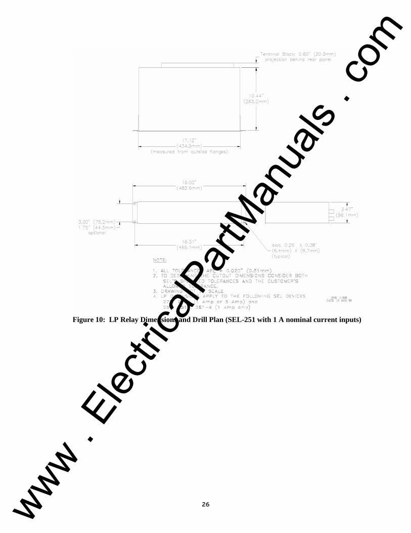
The SEL-251 Relay (with 1 A nominal current inputs) is housed in a low profile (LP) chassis (see Figure 10 for dimensions).
The SEL-251 and SEL-251D Relays are standard with Conventional Terminal Blocks and standard-duty output contacts. The SEL-251 Relay can be optionally ordered as a Connectorized® model, which features plug-in connectors and high-current interrupting output contacts (polarity-sensitive).
How to Order
Contact your SEL Representative for ordering information. Do not order your relay from this Data Sheet, as some combinations of features may be unavailable.
GENERAL SPECIFICATIONS
AC Voltage Inputs
Wye-Connected (SEL-251): 120 V nominal phase-to-neutral, three-phase, four-wire connection (connect any voltage up to 150 Vac). 150 V phase-to-neutral saturation limit.
Delta-Connected (SEL-251D): 120 V nominal phase-to-phase, three-phase, three-wire connection 150 V phase-to-phase saturation limit
AC Current Inputs
5 A nominal 1 A nominal (some models, LP chassis only) 15 A continuous 3 A continuous 110 A saturation limit 20 A saturation limit 500 A 1-second thermal rating 100 A 1-second thermal rating
Frequency and Rotation
60 Hz, ABC (50 Hz is an available ordering option for some models, ACB rotation is an available ordering option for some models)
www . El
ectric
alPar
tMan
uals
. com

6
Output Contact Current Ratings
Conventional Terminal Blocks Per IEC 255-0-20 : 1974, using the simplified method of assessment 6 A continuous carry 30 A make per IEEE C37.90 : 1989 100 A for one second 270 Vac/360 Vdc MOV for differential surge protection. Pickup/dropout time: < 5 ms Breaking Capacity (L/R = 40 ms): 48 V 0.5 A 10,000 operations 125 V 0.3 A 10,000 operations 250 V 0.2 A 10,000 operations Cyclic Capacity (L/R = 40 ms): 48 V 0.5 A 2.5 cycles per second 125 V 0.3 A 2.5 cycles per second 250 V 0.2 A 2.5 cycles per second
Plug-In Connectors (high-current interrupting) 6 A continuous carry 30 A make per IEEE C37.90 : 1989 330 Vdc MOV for differential surge protection Pickup time: < 5 ms Dropout time: < 8 ms (typical) Breaking Capacity: 10 A 10,000 operations 48 and 125 V (L/R = 40 ms) 250 V (L/R = 20 ms) Cyclic Capacity: 10 A 4 cycles in 1 second, followed by 2 minutes idle for thermal dissipation 48 and 125 V (L/R = 40 ms) 250 V (L/R = 20 ms)
Note: Do not use high-current interrupting output contacts to switch ac control signals. These outputs are polarity dependent.
Optioisolated Inputs
The SEL-251 available input ratings are different for the three chassis types. The nominal input rating is not field adjustable – it is determined at the time of order, and is identical for all six inputs. The inputs are not polarity dependent.
Conventional Terminal Blocks – SLP chassis (5 A nominal current inputs)
Nominal Input Rating
Operating Range
Burden at Rated Voltage
Level Sensitive?
24 Vdc 15 – 30 Vdc 4 mA No 48 Vdc 30 – 60 Vdc 4 mA No
125 Vdc 100 – 150 Vdc 6 mA Yes, off below 75 Vdc 250 Vdc 150 – 300 Vdc 4 mA No
www . El
ectric
alPar
tMan
uals
. com

7
Conventional Terminal Blocks – LP chassis (1 A nominal current inputs)
Nominal Input Rating
Operating Range
Burden at Rated Voltage
Level Sensitive?
24 Vdc 15 – 30 Vdc 4 mA No 48 Vdc 30 – 60 Vdc 4 mA No
125 Vdc 80 – 150 Vdc 4 mA No 250 Vdc 150 – 300 Vdc 4 mA No
Plug-In Connectors
Nominal Input Rating
Operating Range
Burden at Rated Voltage
Level Sensitive?
24 Vdc 15 – 30 Vdc 4 mA No 48 Vdc 38 – 60 Vdc 5 mA Yes, off below 29 Vdc
125 Vdc 100 – 150 Vdc 6 mA Yes, off below 75 Vdc 250 Vdc 150 – 300 Vdc 4 mA No
Power Supply 24/48 V: 20 – 60 Vdc; 125/250 V: 85 – 350 Vdc or 85 – 264 Vac 10 W nominal, 14 W maximum (all output relays energized)
Communications Two EIA-232 serial communications ports, Port 2 of the SEL-251 Relay has front-and rear-panel connectors
Dimensions See Figure 9 for SLP chassis (5 A nominal current input models) See Figure 10 for LP chassis (1 A nominal current input models)
Time Code Input Relay accepts demodulated IRIG-B time code input
Mounting Available in horizontal and vertical mounting configurations
Dielectric Strength
V, I inputs: 2500 Vac for 10 seconds Other: 3000 Vdc for 10 seconds (excludes EIA-232) Routine Tested
Operating Temperature
-40° to 158°F (-40° to 70°C)
Environmental Type Tests
IEEE C37.90-1989 IEEE Standards for Relays and Relay Systems Associated with Electrical Power Apparatus, Section 8: Dielectric Tests Severity Level: 2500 Vac on analog inputs; 3000 Vdc on power supply, contact inputs and contact outputs
IEEE C37.90.1-1989 IEEE Standard Surge Withstand Capability (SWC) Tests for Protective Relays and Relay Systems Severity Level: 3.0 kV oscillatory, 5.0 kV fast transient
www . El
ectric
alPar
tMan
uals
. com

8
IEEE C37.90.2 (Issued for trial use December 1987) IEEE Trial-Use Standard, Withstand Capability of Relay Systems to Radiated Electromagnetic Interference from Transceivers Severity Level: 10 V/m
Exceptions:
5.5.2 (2) Performed with 200 frequency steps per octave 5.5.3 Digital Equipment Modulation Test not performed 5.5.4 Test signal turned off between frequency steps to simulate
keying
IEC 68-2-1 Fifth Edition - 1990 Environmental testing, Part 2: Tests - Test Ad: Cold Severity Level: 16 hours at -40°C
IEC 68-2-2 Fourth Edition - 1974 Environmental testing, Part 2: Tests - Test Bd: Dry heat Severity Level: 16 hours at +85°C
IEC 68-2-30 Second Edition - 1980 Basic environmental testing procedures, Part 2: Tests - Test Db and guidance: Damp heat, cyclic (12 + 12-hour cycle) Severity Level: 55°C, 6 cycles
IEC 255-5 First Edition - 1977 Electrical relays, Part 5: Insulation tests for electrical relays, Section 6: Dielectric Tests Severity Level: Series C (2500 Vac on analog inputs; 3000 Vdc on power supply, contact inputs and contact outputs) Section 8: Impulse Voltage Tests Severity Level: 0.5 Joule, 5000 volt
IEC 255-21-1 First Edition - 1988 Electrical relays, Part 21: Vibration, shock, bump, and seismic tests on measuring relays and protection equipment, Section One - Vibration tests (sinusoidal) Severity Level: Class 1
IEC 255-21-2 First Edition - 1988 Electrical relays, Part 21: Vibration, shock, bump, and seismic tests on measuring relays and protection equipment, Section Two - Shock and bump tests Severity Level: Class 1
IEC 255-22-1 First Edition - 1988 Electrical disturbance tests for measuring relays and protection equipment, Part 1: 1 MHz burst disturbance tests Severity Level: 2.5 kV peak common mode, 1.0 kV peak differential mode
IEC 255-22-3 - 1989 Electrical relays, Part 22: Electrical disturbance tests for measuring relays and protection equipment, Section Three - Radiated electromagnetic field disturbance tests
www . El
ectric
alPar
tMan
uals
. com

9
Exceptions:
4.3.2.2 Frequency sweep approximated with 200 frequency steps per octave
IEC 801-2 Second Edition - 1991-04 Electromagnetic compatibility for industrial-process measurement and control equipment, Part 2: Electrostatic discharge requirements Severity Level: 3
IEC 801-3 Electromagnetic compatibility for industrial process measurement and control equipment, Part 3: Radiated electromagnetic field requirements Severity Level: 10 V/m
Exceptions:
9.1 Frequency sweep approximated with 200 frequency steps per octave.
IEC 801-4 First Edition - 1988 Electromagnetic compatibility for industrial process measurements and control equipment, Part 4: Electrical fast transient/burst requirements Severity Level: 4 (4 kV on power supply, 2 kV on inputs and outputs)
Unit Weight SLP chassis: 12 lbs (5.5 kg) – 5 A nominal current inputs LP chassis: 16 lbs (7.3 kg) – 1 A nominal current inputs
Figure 1: SEL-251 Conventional Terminal Block Model Inputs, Outputs, and Targets Diagram
www . El
ectric
alPar
tMan
uals
. com

10
Notes: a) Plug-In Connector models have “+” polarity marks on terminals 2, 4, 6, 8, 10, 12, 14, and 16 (see Figure 8, rear view);
b) Plug-In Connector model output contacts (except ALARM) cannot be configured as Form B contacts, these are all Form A contacts, while the ALARM contact is always Form B;
c) The TARGET LEDs are different on “-1” relays. See text following Figure 3 for details.
FUNCTIONAL SPECIFICATIONS
Overcurrent Elements
Values are shown for 5 A nominal current input models. (Divide current values by five for 1 A nominal current input models.)
Phase Overcurrent Elements for Phase and Three-Phase Faults (51T, 50LT, 50H, 50C)
51T Phase Time-Overcurrent Element • Curve families: moderately inverse, inverse, very inverse, extremely inverse
(additional selection on “-1” models: short-time inverse) • Time dial: 0.5 to 15.00 in 0.01 steps. • Pickup (51P): 1 to 12 A ±2% of setting ±0.1 A secondary • Time delay or one-cycle reset time • Timing: ±5% and ±1 cycle for currents between 2 and 20 multiples of pickup • Internally and externally torque controllable
50LT Phase Definite-Time Overcurrent Element • Pickup (50L): 0.5 to 100 A ±2% of setting ±0.1 A secondary • Time delay: 0 to 16,000 cycles in one-cycle steps • Internally and externally torque controllable
50H Phase Instantaneous Overcurrent Element • Pickup: 0.5 to 100 A ±2% of setting ±0.1 A secondary • Internally and externally torque controllable
50C Phase Instantaneous Overcurrent Element • Pickup: 0.5 to 100 A ±2% of setting ±0.1 A secondary • Can be used to override voltage control through TCI setting choice
Negative-Sequence Overcurrent Elements for Phase-to-Phase Faults (51QT, 50QT) (not present in “-1” models)
51QT Negative-Sequence Time-Overcurrent Element • Element measures 3xI2 negative-sequence current • Curve families: moderately inverse, inverse, very inverse, extremely inverse • Time dial: 0.5 to 15.00 in 0.01 steps • Pickup (51QP): 1 to 12 A ±3% of setting ±0.18 A secondary • Time delay or one-cycle reset time • Timing: ±5% and ±1 cycle for currents between 2 and 20 multiples of pickup • Externally torque controllable
www . El
ectric
alPar
tMan
uals
. com

11
50QT Negative-Sequence Definite-Time Overcurrent Element • Element measures 3xI2 negative-sequence current • Pickup (50Q): 0.5 to 100 A ±3% of setting ±0.18 A secondary • Time delay: 0 to 16,000 cycles in one-cycle steps • Externally torque controllable
Extra Ground/Residual Overcurrent Elements for Gound Faults in “-1” models (51GT, 50GT)
51GT Ground/Residual Time-Overcurrent Element • Similar specifications to 51T element, except 51G pickup setting range is 1 to 12 A,
± 3 percent of the setting, ± 0.18 A secondary, and is externally torque-controllable.
50GT Ground/Residual Definite Time-Overcurrent Element • Similar specifications to 50LT element, except 50G pickup setting range is 0.5 to
100 A, ± 3 percent of setting, ± 0.18 A secondary, and is externally torque-controllable.
Residual Overcurrent Elements for Ground Faults (51NT, 50NLT, 50NH)
51NT Ground/Residual Time-Overcurrent Element • Curve families: moderately inverse, inverse, very inverse, extremely inverse
(additional selection on “-1” models: short-time inverse) • Time dial: 0.5 to 15.00 in 0.01 steps • Pickup (51NP): 0.25 to 12 A secondary • Time delay or one-cycle reset time • Timing: ±5% and ±1 cycle for currents between 2 and 20 multiples of pickup • Externally torque-controllable
50NLT Ground/Residual Definite-Time Overcurrent Element • Pickup (50NL): 0.5 to 100 A secondary (for 1 ≤ 51NP ≤ 12 A secondary) • 0.25 to 50 A secondary (for 0.5 ≤ 51NP < 1 A secondary) • 0.125 to 25 A secondary (for 0.25 ≤ 51NP < 0.5 A secondary) • Time delay: 0 to 16,000 cycles in one-cycle steps • Externally torque-controllable
50NH Ground/Residual Instantaneous Overcurrent Element • Pickup: same range as 50NLT • Externally torque controllable
Accuracy • Residual element pickup accuracy is dependent upon the 51NP setting. Pickup
accuracy of the 51NP, 50NL, and 50NH elements is shown below in the given 51NP setting range.
1.0 ≤ 51NP ≤ 12.0 A sec Pickup ±2% ±0.100 A sec 0.5 ≤ 51NP < 1.0 A sec Pickup ±2% ±0.050 A sec 0.25 ≤ 51NP < 0.5 A sec Pickup ±2% ±0.025 A sec
www . El
ectric
alPar
tMan
uals
. com

12
Voltage Element for Internal Torque Control or Transformer Blown-Fuse Detection (27)
• 27AB, 27BC, 27CA Phase-to-Phase Voltage Elements • Setting Range: 0 to 250 V line-to-line secondary ±5%, ±1 V • Two setting limits: 27H and 27L (high and low, respectively) • 27 element asserts only if voltage is between 27H and 27L • User selects either three-phase or phase-to-phase voltage condition • Implement undervoltage load-shedding scheme • Internally torque-control selected phase overcurrent elements • Detect operation of transformer high-side fuses
Time-Delayed 52A or 52B Functions Handle Fuse-Saving and Inrush
The time-delay pickup and time-delay dropout time settings (52APU and 52ADO, respectively) are provided to generate the 52AT and 52BT functions. The 52AT and 52BT bits can be used to supervise overcurrent elements for fuse-saving and inrush conditions.
Demand Current Thresholds Alarm for Overload and Unbalance
Settable demand current thresholds are available for the phase, negative-sequence, and ground/residual demand ammeters. When demand current exceeds a threshold, the respective Relay Word bit PDEM, QDEM, or NDEM asserts.
PDEM, QDEM, or NDEM alarm for phase overload, negative-sequence unbalance, or residual unbalance, respectively. They can provide advance warning of encroachment on relay overcurrent element pickups. The same demand ammeter time constant (DATC = 5 to 60 minutes, in one minute increments) is used for all three demand ammeters.
Trip Failure Timer Detects Breaker Failure or Slow Trip
A relay trip starts a trip failure timer. If the trip condition lasts longer than the TFT setting, the TF bit in the Relay Word asserts. The TF bit deasserts 60 cycles after the trip condition drops out. The TF bit can be assigned to an output contact to alarm for slow trips or to provide breaker failure tripping. It can also be used to cancel reclosing or trigger an event report.
Close Failure Timer Detects Failure to Close or Slow Close
A Close Failure Timer controls the length of time the CLOSE output contact remains asserted. If CLOSE output contact assertion exceeds the CFT time setting, the close attempt is unsuccessful. The relay opens the CLOSE output contact, the reclosing relay locks out, and the CF bit in the Relay Word asserts. The CF bit asserts for 60 cycles. Use the CF bit to alarm for close failures, slow-close conditions, and to trigger event reports.
If time setting CFT=0, the close failure timer is defeated and the CLOSE output contact remains asserted until the circuit breaker status input indicates that the circuit breaker is closed.
Trip Circuit Monitor Alarm Checks Trip Circuit and Verifies Circuit Breaker Status Input
You can assign one of the six programmable inputs to the trip circuit monitor (TCM) logic and wire it in parallel with the TRIP output contact.
www . El
ectric
alPar
tMan
uals
. com

13
The TCM logic ensures that the circuit breaker status and TCM inputs agree. If the two inputs disagree for at least 60 cycles, the trip circuit monitor alarm (TCMA) bit asserts in the Relay Word. The TCMA bit deasserts 60 cycles after the TCMA condition drops out. The TCMA bit can be used to alarm, cancel reclosing, or trigger event reports.
SEL-251 RELAY SELOGIC CONTROL EQUATIONS
SELOGIC control equations put relay logic in the hands of the relay application engineer. Assign the inputs to suit your application, logically combine selected relay elements for various control functions, use non-dedicated timers for special applications, and assign output contacts to your logic functions.
Programming SELOGIC control equations consist of assigning functions to the programmable inputs, designing the internal logic you need, expressing that logic in terms of the relay elements and internal logic variables, and defining the output functions. Complete all SELOGIC control equations programming using the SET command.
Figure 2: SEL-251 Relay SELOGIC Control Equations Block Diagram
www . El
ectric
alPar
tMan
uals
. com
14
Assign Inputs to the Functions You Need
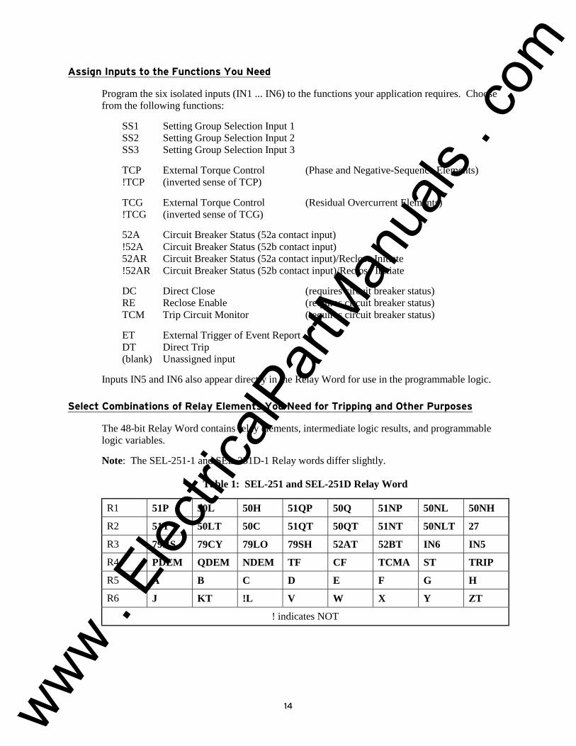
Program the six isolated inputs (IN1 ... IN6) to the functions your application requires. Choose from the following functions:
SS1 Setting Group Selection Input 1 SS2 Setting Group Selection Input 2 SS3 Setting Group Selection Input 3
TCP External Torque Control (Phase and Negative-Sequence Elements) !TCP (inverted sense of TCP)
TCG External Torque Control (Residual Overcurrent Elements) !TCG (inverted sense of TCG)
52A Circuit Breaker Status (52a contact input) !52A Circuit Breaker Status (52b contact input) 52AR Circuit Breaker Status (52a contact input)/Reclose Initiate !52AR Circuit Breaker Status (52b contact input)/Reclose Initiate
DC Direct Close (requires circuit breaker status) RE Reclose Enable (requires circuit breaker status) TCM Trip Circuit Monitor (requires circuit breaker status)
ET External Trigger of Event Report DT Direct Trip (blank) Unassigned input
Inputs IN5 and IN6 also appear directly in the Relay Word for use in the programmable logic.
Select Combinations of Relay Elements You Need for Tripping and Other Purposes
The 48-bit Relay Word contains relay elements, intermediate logic results, and programmable logic variables.
Note: The SEL-251-1 and SEL-251D-1 Relay words differ slightly.
Table 1: SEL-251 and SEL-251D Relay Word
R1 51P 50L 50H 51QP 50Q 51NP 50NL 50NH
R2 51T 50LT 50C 51QT 50QT 51NT 50NLT 27
R3 79RS 79CY 79LO 79SH 52AT 52BT IN6 IN5
R4 PDEM QDEM NDEM TF CF TCMA ST TRIP
R5 A B C D E F G H
R6 J KT !L V W X Y ZT
! indicates NOT
www . El
ectric
alPar
tMan
uals
. com

15
51P Phase time-overcurrent element pickup 50L Phase definite-time overcurrent element pickup 50H Phase instantaneous overcurrent element 51QP Negative-sequence time-overcurrent element pickup 50Q Negative-sequence definite-time overcurrent element pickup 51NP Ground/Residual time-overcurrent element pickup 50NL Ground/Residual definite-time overcurrent element pickup 50NH Ground/Residual instantaneous overcurrent element 51T Phase time-overcurrent element 50LT Phase definite-time overcurrent element 50C Phase instantaneous overcurrent element (can override voltage control by 27) 51QT Negative-sequence time-overcurrent element 50QT Negative-sequence definite-time overcurrent element 51NT Ground/Residual time-overcurrent element 50NLT Ground/Residual definite-time overcurrent element 27 Voltage element (phase-phase or three-phase undervoltage or transformer blown fuse) 79RS Reclosing relay is in the reset state 79CY Reclosing relay is in the reclose cycle state 79LO Reclosing relay is in the lockout state 79SH "Shot" bit; asserts for shots selected by the M79SH setting 52AT Time delayed 52A 52BT Inverse of 52AT IN6 Input IN6 bit; asserts for control voltage applied to input IN6 IN5 Input IN5 bit; asserts for control voltage applied to input IN5 PDEM Phase demand current threshold exceeded QDEM Negative-sequence demand current threshold exceeded NDEM Ground/Residual demand current threshold exceeded TF Trip failure condition CF Close failure condition TCMA Trip circuit monitor alarm: asserts for abnormal open or short circuit in the circuit breaker
tripping circuit or circuit breaker status input (52A) ST Output from timer TS, driven by any OR-combination of elements in R1 through R3 assigned
to setting S TRIP Follows the state of the TRIP output contacts A B C D Select any OR-combination of elements in R1 and R2 E F G H Select any OR-combination of elements in R3 and R4 J Select any OR-combination of elements in R1 through R4 KT Output from timer TK, driven by any selected OR-combination of elements in R1 through R4
assigned to setting K !L Output from an inverter, driven by any selected OR-combination of elements in R1 through
R4 assigned to setting L V W X Y Select any AND-combination of elements A through !L ZT Output from timer TZ, driven by any selected AND-combination of elements A through !L
assigned to setting Z
www . El
ectric
alPar
tMan
uals
. com

16
Program the Output Contacts
Write output equations to define tripping and other control functions.
TRIP: Select any OR-combination of elements in R1, R2, R4, and R6 Direct Trip (DT) input and the OPEN command also assert TRIP A1, A2: Select any OR-combination of elements in R1, R2, R3, and R4 A3: Select any OR-combination of elements in R1, R3, R4, and R6 A4: Select any OR-combination of elements in R2, R3, R4, and R6 Optionally, A4 can operate as an ALARM
The CLOSE and ALARM functions have dedicated outputs:
CLOSE: Asserted by reclosing relay, Direct Close (DC) input, or CLOSE command ALARM: Asserts when any self-test enters a warning or failure state
On Conventional Terminal Block Relays all output contacts may be configured as "a" or "b" contacts with soldered wire jumpers.
Use the SHOWSET Command to See the Logic Equations
Use the SHOWSET command to print all of relay settings, including the SELOGIC control equations configuration.
SELOGIC Control Equations Settings are Part of Each Setting Group
When you switch groups, you switch logic settings as well as relay element settings. So, the six groups can be programmed for different operating conditions, such as feeder paralleling, station maintenance, seasonal operations, and cogeneration on/off.
TARGETS
Read targeting information locally by inspecting the front panel LEDs, remotely using the TARGET command or reading the event reports.
The INST target indicates no overcurrent condition in Relay Word row R1 was asserted longer than the ITT (instantaneous target time) timer setting before the TRIP output contacts asserted. The ITT setting gives you control over what is considered a "close-in" fault.
The phase current indicators (A, B, C) show which phases were above the 51P pickup setting at the time of trip.
The negative-sequence and residual current indicators (Q, N) similarly show if these currents were above the respective 51QP and 51NP pickup settings at the time of trip.
The RS and LO indicators show the state of the reclosing relay (reset or lockout).
Figure 3: SEL-251 and SEL-251D Relay Front-Panel Target LEDs
www . El
ectric
alPar
tMan
uals
. com
17
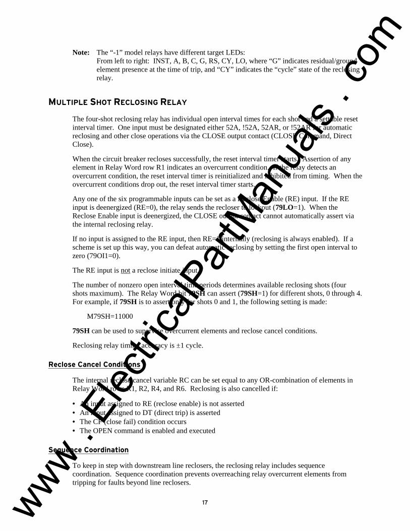
Note: The “-1” model relays have different target LEDs: From left to right: INST, A, B, C, G, RS, CY, LO, where “G” indicates residual/ground element presence at the time of trip, and “CY” indicates the “cycle” state of the reclosing relay.
MULTIPLE SHOT RECLOSING RELAY
The four-shot reclosing relay has individual open interval times for each shot and a settable reset interval timer. One input must be designated either 52A, !52A, 52AR, or !52AR for automatic reclosing and other close operations via the CLOSE output contact (CLOSE Command, Direct Close).
When the circuit breaker recloses successfully, the reset interval timer starts. Assertion of any element in Relay Word row R1 indicates an overcurrent condition. If the relay detects an overcurrent condition, the reset interval timer is reinitialized and inhibited from timing. When the overcurrent conditions drop out, the reset interval timer starts.
Any one of the six programmable inputs can be set as a Reclose Enable (RE) input. If the RE input is deenergized (RE=0), the relay sends the recloser to lockout (79LO=1). When the Reclose Enable input is deenergized, the CLOSE output contact cannot automatically assert via the internal reclosing relay.
If no input is assigned to the RE input, then RE=1 internally (reclosing is always enabled). If a scheme is set up this way, you can defeat automatic reclosing by setting the first open interval to zero (79OI1=0).
The RE input is not a reclose initiate input.
The number of nonzero open interval time periods determines available reclosing shots (four shots maximum). The Relay Word bit 79SH can assert (79SH=1) for different shots, 0 through 4. For example, if 79SH is to assert only for shots 0 and 1, the following setting is made:
M79SH=11000
79SH can be used to supervise overcurrent elements and reclose cancel conditions.
Reclosing relay timing accuracy is ±1 cycle.
Reclose Cancel Conditions
The internal reclose cancel variable RC can be set equal to any OR-combination of elements in Relay Word rows R1, R2, R4, and R6. Reclosing is also cancelled if:
• An input assigned to RE (reclose enable) is not asserted • An input assigned to DT (direct trip) is asserted • The CF (close fail) condition occurs • The OPEN command is enabled and executed
Sequence Coordination
To keep in step with downstream line reclosers, the reclosing relay includes sequence coordination. Sequence coordination prevents overreaching relay overcurrent elements from tripping for faults beyond line reclosers.
www . El
ectric
alPar
tMan
uals
. com

18
You can set the internal variable SEQ to any OR-combination of elements in Relay Word row R1. The combination you select determines which overcurrent conditions control sequence coordination. If no trip output is present and the breaker is closed, SEQ assertion followed by dropout advances the shot counter. Advancing the shot counter keeps the SEL-251 Relay in step with the line recloser.
SELECTABLE SETTING GROUPS
The relay accepts six separate groups of relay and logic settings.
The relay determines which group of settings and logic to use by monitoring the setting group selection inputs (SS1, SS2, and SS3) or by the GROUP command. To use inputs, program one or more of the setting selection inputs (SS1, SS2, SS3) to one or more respective inputs.
Program relay elements and logic with the SET command.
CIRCUIT BREAKER MONITOR
The SEL-251 Relay detects every circuit breaker trip operation. It designates each trip as one caused by the relay or an external trip and maintains a running count of each.
The relay also maintains a running sum of the interrupted current in each circuit breaker pole for relay and external trips. Running sums for relay trips use the current present when the trip output contacts are asserted. Running sums for external trips use the currents present when the circuit breaker status input indicates that the circuit breaker is opening.
Display the circuit breaker operation data using the BREAKER command.
=>BREAKER <ENTER>BREAKER <ENTER>BREAKER <ENTER>BREAKER <ENTER> Example 21.6 kV distribution feeder Date: 1/5/93 Time: 09:09:58 Rly Trips=15 From: 1/1/92 01:01:01 IA=42650 IB=37910 IC=34200 Ext Trips=2 From: 1/1/92 01:01:01 IA=650 IB=670 IC=620
Circuit breaker operation data can be reset by command.
METERING
The SEL-251 Relay provides complete voltage and current metering. It also determines real and reactive power values, demand values, peak demand values, and negative- and zero-sequence components of the voltages and currents (see note following the METER Command sample printout).
Demand ammeters with 5- to 60-minute time constants show phase, negative-sequence, and zero-sequence (ground/residual) demand currents. Peak demands are saved.
Display metering data using the METER and METER D commands (present and demand metering information, respectively).
www . El
ectric
alPar
tMan
uals
. com

19
=>METER METER METER METER <ENTER><ENTER><ENTER><ENTER> Example 21.6 kV distribution feeder Date: 1/5/93 Time: 09:10:49 MET IA=356 B=364 C=361 R=6 3I2=5 P=12.910 Q=1.130 VA=12021 VB=12015 VC=12043 3V0=20 AB=20827 BC=20839 CA=20836 3V2=17
Note: VA, VB, VC, 3V0, and 3V2 quantities are not available on the SEL-251D Relays. 3I2 quantities are not available on the “-1” Relays.
=>METER D <ENTER> METER D <ENTER> METER D <ENTER> METER D <ENTER> Example 21.6 kV distribution feeder Date: 1/5/93 Time: 09:11:03 DEM IA=347 B=349 C=349 R=4 3I2=3 P=12.897 Q=0.997 PK IA=412 B=410 C=414 R=15 3I2=13 P=14.701 Q=1.280
Demand and peak demand metering information can also be reset by command.
HISTORY SUMMARY
The HISTORY command quickly retrieves summaries of the last twelve event records, as shown in the following example.
=>HISTORY <ENTER> HISTORY <ENTER> HISTORY <ENTER> HISTORY <ENTER> Example 21.6 kV distribution feeder Date: 1/5/93 Time: 09:10:27 # DATE TIME EVENT LOCAT SHOT CURR GROUP TARGETS 1 1/5/93 01:36:59.070 AG T 2.43 0 2798 2 INSTAQN 2 12/17/92 08:07:40.129 CG T 3.52 1 2361 3 INSTCQN 3 12/17/92 08:07:35.133 CG T 3.51 0 2364 3 INSTCQN 4 12/15/92 01:07:35.862 TRIG 0 345 1 5 6 7 8 9 10 11 12
www . El
ectric
alPar
tMan
uals
. com

20
AC CONNECTIONS
Figure 4: SEL-251 Relay Typical AC Current and Voltage Connections
Figure 5: SEL-251D Relay Typical AC External Current and Voltage Connections
www . El
ectric
alPar
tMan
uals
. com
21
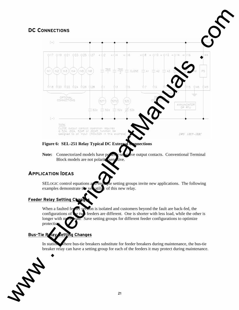
DC CONNECTIONS
Figure 6: SEL-251 Relay Typical DC External Connections
Note: Connectorized models have polarity-sensitive output contacts. Conventional Terminal Block models are not polarity-sensitive.
APPLICATION IDEAS
SELOGIC control equations and multiple setting groups invite new applications. The following examples demonstrate the versatility of this new relay.
Feeder Relay Setting Changes
When a faulted feeder section is isolated and customers beyond the fault are back-fed, the configurations of the two feeders are different. One is shorter with less load, while the other is longer with more load. Save setting groups for different feeder configurations to optimize protection.
Bus-Tie Relay Setting Changes
In stations where bus-tie breakers substitute for feeder breakers during maintenance, the bus-tie breaker relay can have a setting group for each of the feeders it may protect during maintenance.
www . El
ectric
alPar
tMan
uals
. com
22
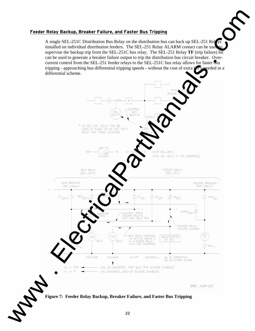
Feeder Relay Backup, Breaker Failure, and Faster Bus Tripping
A single SEL-251C Distribution Bus Relay on the distribution bus can back up SEL-251 Relays installed on individual distribution feeders. The SEL-251 Relay ALARM contact can be used to supervise the backup trip from the SEL-251C bus relay. The SEL-251 Relay TF (trip failure) bit can be used to generate a breaker failure output to trip the distribution bus circuit breaker. Over-current control from the SEL-251 feeder relays to the SEL-251C bus relay allows for faster bus tripping - approaching bus differential tripping speeds - without the cost of extra CT's needed in a differential scheme.
Figure 7: Feeder Relay Backup, Breaker Failure, and Faster Bus Tripping
www . El
ectric
alPar
tMan
uals
. com

23
EVENT REPORT
The SEL-251 Relay event report displays current and voltage quantities in primary units every quarter-cycle for eleven cycles. The relay uses a simple process to encode relay element states, outputs, and inputs, which makes the report compact and easy to interpret. Event reports can be generated for fault, cold load inrush, and other conditions.
Event Report Triggering
Set the internal variable ER to any OR-combination of elements in Relay Word rows R1, R2, R4, and R6 to trigger an event report for any desired combination of conditions the relay can detect. Event reports also trigger if:
• The TRIP output contacts are asserted • An input assigned to the ET (External Trigger) function is asserted • The TRIGGER command is executed
Event Report Column Headings
(SEL-251 event report column headings shown. There are minor differences in the SEL-251D and “-1” model event reports column headings.)
Currents Primary Amps IR residual current IA A-phase current IB B-phase current IC C-phase current
Voltages Primary Volts VA A-phase voltage VB B-phase voltage VC C-phase voltage
P Phase Elements 51 phase time-overcurrent element 50L phase definite-time overcurrent
element 50H phase instantaneous overcurrent
element TCI internal torque control conditions
Q Negative-Sequence Elements 51 negative-sequence time-overcurrent
element 50 negative-sequence definite-time
overcurrent element
N Ground/Residual Elements 51 ground/residual time-overcurrent
element 50L ground/residual definite-time
overcurrent element 50H ground/residual instantaneous
overcurrent element
I Demand Current DEM phase, negative-sequence, and
residual demand current thresholds
79 reclosing relay states (reset, reclosing cycle, lockout)
BKR circuit breaker alarm conditions (trip failure, close failure, and trip coil monitor alarms)
Out Output Contacts T&C TRIP and CLOSE output contacts 1&2 A1 and A2 output contacts 3&4 A3 and A4 output contacts ALR ALARM output contact
In Inputs 1&2 IN1 and IN2 inputs 3&4 IN3 and IN4 inputs 5&6 IN5 and IN6 inputs
www . El
ectric
alPar
tMan
uals
. com
24
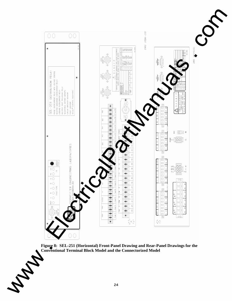
Figure 8: SEL-251 (Horizontal) Front-Panel Drawing and Rear-Panel Drawings for the Conventional Terminal Block Model and the Connectorized Model
www . El
ectric
alPar
tMan
uals
. com

25
Figure 9: SLP Relay Dimensions and Drill Plan (SEL-251 with 5 A nominal current inputs)
www . El
ectric
alPar
tMan
uals
. com
26
Figure 10: LP Relay Dimensions and Drill Plan (SEL-251 with 1 A nominal current inputs)
www . El
ectric
alPar
tMan
uals
. com

27
Figure 11: Panel-Cutout Diagram for SEL-200 Series Panel-Mount Relays
FACTORY ASSISTANCE
The employee-owners of Schweitzer Engineering Laboratories are dedicated to making electric power safer, more reliable, and more economical.
We appreciate your interest in SEL products, and we are committed to making sure you are satisfied. If you have any questions, please contact us at:
Schweitzer Engineering Laboratories 2350 NE Hopkins Court Pullman, WA USA 99163-5603 Tel: (509) 332-1890 Fax: (509) 332-7990
We guarantee prompt, courteous, and professional service.
We appreciate receiving any comments and suggestions about new products or product improvements that would help us make your job easier.
www . El
ectric
alPar
tMan
uals
. com

All brand or product names appearing in this document are the trademark or registered trademark of their respective holders.
Schweitzer Engineering Laboratories, SELOGIC, Connectorized, and are registered trademarks of Schweitzer Engineering Laboratories.
This product is covered by U.S. Patent No: 5,041,737; 5,477,408; 5,479,315; 5,602,7078.
Copyright © SEL 1992, 1993, 1995, 1996, 2000 (All rights reserved) Printed in USA.
SEL-251 Data Sheet Date Code 20000417
www . El
ectric
alPar
tMan
uals
. com