Embed Size (px)
Citation preview

ORIGINAL ARTICLE
Seismic retrofitting solution of an adobe masonry wall
A. Figueiredo • H. Varum • A. Costa •
D. Silveira • C. Oliveira
Received: 22 March 2011 / Accepted: 25 June 2012
� RILEM 2012
Abstract Adobe constructions represent a high
percentage of the national patrimony, with high
historical, cultural and architectonic value. Well-
preserved adobe structures can exhibit a particular
architecture with very attractive geometric character-
istics while also incorporating natural materials.
However, the behavior of these structures is deficient
under horizontal loads, such as those induced by an
earthquake, which endangers their structural integrity
and human lives. To develop a seismic retrofit
solution, a real-scale wall was characterized and
tested by considering permanent vertical actions with
cyclic horizontal forces of increasing amplitude. To
retrofit the wall, repair and seismic reinforcement
solutions were developed and combined to evaluate
their efficiencies. To repair the damages, hydraulic
lime gum was injected by pressure into the cracks. The
reinforcement solution included the use of a synthetic
mesh in the wall. The retrofitted wall was then tested,
and the results indicated that the retrofit solutions
significantly improved the seismic performance of the
wall. This study contributes to the characterization of
walls constructed with adobe masonry and their
behavior under horizontal actions. Furthermore, an
economic, sustainable and efficient solution is pre-
sented for the retrofitting of adobe walls, with
significant performance improvements obtained.
Keywords Adobe structures � Mechanical
properties � Structural behavior � Seismic assessment �Seismic strengthening techniques
1 Introduction
Earth is one of the oldest construction materials in use.
The unique properties and accessibility of this material
justify its wide dissemination and continued use over
time. There is no consensus regarding the exact period
of time when humans began to use earth as a
construction material. Houben and Guillaud [9] find
that the use of sun-dried blocks composed of argilla-
ceous earth (adobe) dates back to 8,000 B.C. Minke
[13] affirms that the use of earth construction by our
ancestors began more than 9,000 years ago. Torgal
and Jalali [20] identify the beginning of earth
A. Figueiredo � H. Varum (&) � A. Costa �D. Silveira � C. Oliveira
Departamento de Engenharia Civil, Universidade de
Aveiro, 3810-193 Aveiro, Portugal
e-mail: [email protected]
A. Figueiredo
e-mail: [email protected]
A. Costa
e-mail: [email protected]
D. Silveira
e-mail: [email protected]
C. Oliveira
e-mail: [email protected]
Materials and Structures
DOI 10.1617/s11527-012-9895-1

construction with the period in which the first
agricultural societies were developed (12,000 to
7,000 B.C.). Nevertheless, many ancient constructions
have remained intact over time and are now buildings
known worldwide with high cultural and historical
value. Some examples include the Temple of Ramses
II in Gourna (1,200 B.C.), Egypt, the Great Wall of
China (220 B.C.) and the famous Pyramid of the Sun
in Teotihuacan, Mexico (200 B.C.).
With the introduction of new materials and tech-
niques in current constructions, a deceleration, and
sometimes even stagnation, of earth construction has
been verified. Despite this finding, it is estimated that
approximately 30 % of the world’s population still
lives in buildings constructed with earth [9]. A large
percentage of these buildings are currently associated
with rural populations that have low economic
resources. Furthermore, a large portion of the existing
earth constructions is now located in regions where
seismic hazards cannot be disregarded, including
Southern Europe, Western North and South America,
Central America, some regions of Africa, Southern
Asia, and Australia.
In Portugal, earth construction was a very common
practice until the middle of the 20th century. Between
the 1950s and the 1970s, this construction method was
progressively substituted by the use of reinforced
concrete structures combined with ceramic brick
walls. Currently, there are still innumerable buildings
in Portugal that illustrate the various traditional earth
construction techniques. In the southern region of the
country, the dominant construction technique was
rammed earth. In the littoral center, the adobe
construction technique prevailed. The north and
interior center of the country were dominated by
stone masonry construction [27]. In the Beira Alta and
Beira Baixa regions, there is a common traditional
constructive typology that combines stone masonry
and tabique walls, which consist of a wooden struc-
tural system filled with earth [6].
Despite their advantages, adobe constructions have
some problematic characteristics. If not properly
reinforced, this type of construction can exhibit a
deficient response to seismic actions due to the
properties of adobe masonry, such as large mass,
limited tensile strength, fragile behavior, and soften-
ing and loss of strength upon saturation. Under
horizontal actions, these structures can suffer severe
structural damage and sometimes collapse, causing
innumerable human and material losses. The statistics
on losses caused by recent earthquakes in regions
where constructions are mainly composed of adobe
clearly attest to the deficient behavior of these
structures.
In 2001, an earthquake with a momentum magni-
tude (Mw) of 8.4 affected the Peruvian regions of
Arequipa, Moquegua and Tacna, causing the destruc-
tion of 36,000 houses, 25,000 of which were com-
posed of adobe, and the death of 81 people [1]. In the
same year, two earthquakes occurred in El Salvador,
with Mw of 7.7 and 6.6, causing severe damage, or
even collapse, in 200,000 adobe houses and the loss of
1,100 lives [1]. In 2007, another earthquake was felt
along the coast of Peru, 169 km southeast of the
capital, Lima. It reached a magnitude of 8 on the
Richter scale, causing the partial or total destruction of
approximately 38.000 dwellings, the majority of
which were composed of adobe, and resulting in 500
casualties.
The high seismic vulnerability of certain earth
structures, particularly those located in regions of
considerable seismic risk, combined with their present
state of degradation, justifies the investigation and
development of adequate and efficient seismic
strengthening techniques.
2 Previous experimental work: state of the art
Previously, the information regarding scientific results
on the behavior of earth structures and their mechan-
ical properties was extremely insufficient and did not
allow for the development of improved solutions.
However, particularly since the 1970s, there has been
increasing interest in the subject, with different
investigation groups conducting scientific research in
this area.
A research group from the Pontifical Catholic
University of Peru (PUCP) has been playing an
important role in the acquisition of knowledge on
adobe masonry behavior and the development of
reinforcement solutions against earthquakes. The
significant work conducted by this research group in
the last 35 years is reported in detail in Vargas et al.
[21]. In 1973, full-scale adobe cubes were built and
placed in a tipper platform of concrete to analyze and
characterize collapse modes [3]. During the tests, the
Materials and Structures

concrete platform was continuously tilted until the
collapse of the adobe blocks occurred. The collapse
mechanism was evaluated by registering the angle of
the concrete platform with the horizontal direction at
collapse. The seismic action was quantified through
the lateral component of the units’ self-weight. The
results obtained from the units without reinforcement
allowed for the characterization of the collapse modes
typically observed in adobe dwellings during strong
ground motions. From the reinforced units, it was
concluded that the interior reinforcement of adobe
blocks with milled cane in 4 horizontal rows increases
the seismic resistance of the masonry walls.
In 2004, several full-scale adobe walls were tested at
PUCP under cyclic horizontal forces to simulate the
effect of earthquakes. The main purpose of the research
was to assess the viability of incorporating low-cost
materials, such as geosynthetic, plastic or metallic
meshes, in the seismic retrofitting of existing adobe
constructions. The results obtained for the different
reinforcement solutions studied were acceptable, par-
ticularly for the geosynthetic meshes. The improve-
ments in the wall ductility were significant compared
with the specimen without reinforcement. The original
wall registered elastic behavior until a drift of 0.26 %,
with an elastic stiffness of 41 kN/mm. The maximum
strength attained was 41.39 kPa at a drift of 0.10 %.
The test was conducted up to the maximum drift of
2.59 %, with an associated strength of 33.77 kPa. In
contrast, the wall with external geosynthetic mesh
reached a maximum strength of 42.48 kPa at a drift of
1.04 %, presenting an elastic stiffness of 30 kN/mm.
The strengthened wall was able to withstand a max-
imum lateral drift of 5.18 %, which is twice that
withstood by the wall without reinforcement. The
strengthened wall specimen exhibited good signs of
stability, registering only a slight softening [2].
At the Autonomous University of Mexico State,
Noguez and Navarro [15] conducted an experimental
project to repair adobe walls with synthetic meshes.
Five adobe wall models were built, each of which was
2.30 m wide and 2.30 m high. Two walls were built
using traditional adobe bricks, and the remaining three
were built with industrial bricks. The walls studied had
the following characteristics: W1—traditional bricks
without reinforcement; W2—traditional bricks, con-
fined at the top and sides with concrete; W3—
industrial bricks without reinforcement; W4—indus-
trial bricks with the same reinforcement as W2; and
W5—industrial bricks reinforced with chicken wire
mesh. The walls were simultaneously tested under
dead loads and cyclic horizontal loads.
In the first phase of this study, it was concluded that
the walls built with industrial bricks performed
significantly better than the other walls. The mechan-
ical resistance and ductility of the walls increased,
although this type of masonry exhibits fragile ruptures
under horizontal actions.
After the first series of tests, walls W1, W3 and W4
were repaired with a plaster mortar composed of
cement and sand in addition to being reinforced with
synthetic mesh. These walls were tested again under
similar conditions.
It was concluded that synthetic meshes provide an
adequate reinforcement methodology that is accessi-
ble and compatible with the construction technologies
used in adobe buildings [15].
Yamin, together with a group of researchers, tested
18 adobe walls that were 2.50 m wide, 2.00 m high,
and 0.40–0.50 m thick [28]. The walls were tested
under vertical loads combined with cyclic horizontal
loads at the top. These walls had different construction
solutions (no reinforcement, mesh reinforcement or
wood reinforcement) and different materials (adobe or
rammed earth). The results obtained for the adobe
walls tested are shown in Table 1.
The experimental tests demonstrated that the reha-
bilitation techniques under consideration could
slightly improve the seismic behavior of the walls by
providing better structural continuity and confine-
ment, thus reducing structural instability. The appli-
cation of these techniques can reduce the seismic
vulnerability of adobe structures, thus decreasing the
risk associated with human losses or historical
heritage.
Zavala and Igarashi [29] developed experimental
studies on walls with an average length of 2.45 m,
average height of 2.30 m and average thickness of
0.20 m. In the experimental tests, a cyclic horizontal
force was applied at a height of 1.18 m from the wall’s
base in each wall, with the exception of wall 1, for
which the force was applied at its top. For the walls
without reinforcement, a mean drift of 0.04 % was
obtained for an installed horizontal stress of 12.01 kPa.
The maximum drifts and maximum stresses registered
are displayed in Table 2.
Materials and Structures

After these tests, the walls were reinforced with two
different solutions and tested again. The results
obtained are shown in Table 3.
The use of the two reinforcement solutions on the
walls increased their lateral strength capacity, global
strength capacity and deformation capacity. Another
advantage of these reinforcements is their low cost,
which would facilitate their application by populations
with low economic resources.
There is great diversity in adobe masonry world-
wide due to vernacular traditions perpetuated through
generations. This multiplicity of adobe types is due not
only to the variety of soil types used in the different
continents or regions but also to the fact that earth
construction is an enduring construction technique
that has survived through the ages, undergoing alter-
ations over time. Despite all of the work that has
already been performed, there is always the need for
additional research. Existing reinforcement solutions
must be investigated to become fully viable and
applicable. Furthermore, new reinforcement solutions
must be developed to protect adobe structures from
earthquakes and provide a more efficient behavior.
The Department of Civil Engineering of Aveiro
University in Portugal has recently been conducting
several scientific studies on the behavior of adobe
structures located in the Aveiro district. The research
has focused on adobe masonry behavior through
analysis of its composition, resistance, stiffness,
ductility, energy dissipation capacity and collapse
mechanisms. With the results obtained, a meticulous
evaluation regarding the frequent causes of structural
pathologies and fragilities in adobe masonry is being
conducted. These studies have provided important
guidelines for the definitions of reinforcement and
rehabilitation of seismic-resistant structures [4, 5, 7,
12, 16–18, 22–26].
An example of these studies is the 1.06-m-high,
1.02-m-wide, 0.19-m-thick wall that was built and
tested in the laboratory of the Civil Engineering
Department of the University of Aveiro. The material
used in its construction was adobe collected from
traditional buildings in the region. This adobe has a
compression resistance of 1.10 MPa and a Young’s
modulus of 147.3 MPa. The mortar used for the
expansion joints has a compression resistance of
1.42 MPa and a Young’s modulus of 112.8 MPa. In
the experimental tests, a vertical permanent load of
2.86 kN was placed on top of the wall, and horizontal
loads were applied to the wall plane in increasing
amplitude cycles until collapse. The resistance
Table 1 Results from the cyclic tests (adapted from Yamin et al. [28])
Wall Reinforcement Vertical permanent
stress (kPa)
Elastic tension
(kPa)
Maximum
strength (kPa)
Elastic
drift (%)
Maximum
drift (%)
1 No reinforcement 70 20 25 0.03 0.06
2 No reinforcement 50 18 22 0.04 0.07
3 No reinforcement 20 10 12 0.04 0.07
4 Mesh 70 30 36 0.11 0.36
5 Mesh 50 21 36 0.14 0.56
6 Mesh 20 20 32 0.11 0.38
7 Mesh 40 10 26 0.12 0.35
8 Wood 70 16 44 0.08 0.55
9 Wood 20 12 20 0.06 0.31
Table 2 Results of the cyclic test (adapted from [29])
Wall Maximum strength (kPa) Maximum Drift (%)
2 21.62 0.28
3 23.42 0.33
4 23.62 0.37
Table 3 Results of the cyclic test (adapted from [29])
Wall Reinforcement Maximum
strength (kPa)
Maximum
Drift (%)
1 Solution one 33.83 1.72
3 31.03 1.66
2 Solution two 33.43 1.67
4 38.24 1.69
Materials and Structures

capacity of the wall was evaluated at 0.57 kPa with an
approximate drift of 0.37 % [23].
Other in situ tests have been conducted, such as out-
of-plane tests on single-dwelling walls. Horizontal
forces were applied at a height of 2.33 m from the base
of the walls in increasing amplitude cycles until
failure. Elastic behavior was observed at a drift of
0.4 % and a maximum resistance of 0.8 %. The
maximum imposed drift was 3.8 % [23].
The information collected from previous experi-
ments conducted at Aveiro University provides a solid
foundation for the study and development of strength-
ening solutions for adobe structures.
In summary, different studies have been conducted
regarding the mechanical characterization of adobe
structures, their structural behavior and their perfor-
mance under seismic actions. Several studies show
that the incorporation of meshes in the rehabilitation or
strengthening of adobe structures significantly
improves their seismic performance. The studies
presented were conducted using different material
compositions and different geometries or typologies;
thus, a direct association and comparison of results is
not easy. Nevertheless, several studies present rein-
forcement solutions using meshes, resulting in signif-
icant improvements in the structures’ performance.
The adobe structures studied showed maximum
strengths of approximately 12–41 kPa and maximum
drifts of approximately 0.1–2.6 %, while the mesh
reinforcement solution yielded maximum strengths of
approximately 26–43 kPa and maximum drifts of
approximately 0.4–5.2 %, which is more than twice
that of the structures without reinforcement.
3 Development and testing of repair
and strengthening solutions for an adobe
masonry wall
3.1 Overview
The Civil Engineering Department of Aveiro University
has been conducting research on rehabilitation tech-
niques, particularly for adobe construction. The aim of
this experimental study was to conduct a thorough
evaluation of the performance of adobe structures, with
and without seismic retrofitting, with a specific strength-
ening solution. In addition, a cost-effective, undemand-
ing and simple strengthening solution for adobe
construction was intended to be developed for use by
populations facing economic challenges.
A full-scale adobe wall was built in the Civil
Engineering Laboratory of Aveiro University using
adobe blocks from a demolition site in the Aveiro
region. Only traditional techniques and materials were
used in the laboratory to accurately portray existing
structures. A full-scale model was adopted to remove
current limitations in the representation of results
associated with scaled models, as reported by Moham-
med and Hughes [14].
During the experimental tests, a series of dynamic,
cyclic, in-plane tests were carried out on the wall to
evaluate and characterize adobe construction in the
region. After the first series of tests, the damages to the
wall were repaired, and a seismic retrofit solution was
applied. To validate the efficacy of the repair and
retrofitting techniques, a series of dynamic cyclic tests,
following the same procedure that was first applied to
the wall, was performed again.
3.2 Test of the unstrengthened adobe masonry
wall
As mentioned in Sect. 3.1, a full-sized adobe masonry
wall was built with adobe blocks collected from a
demolition site in Aveiro. To simulate an adobe
structure that represented the vast number of adobe
buildings in the district, a mortar using hydraulic lime
was cast in the laboratory and applied to the edification
of the wall. To take the influence of adjacent walls into
account, the wall was built in the shape of a double-T
in plan view. The real-scale adobe wall had a height of
3.07 m, a length of 3.5 m and a mean thickness of
0.29 m (Fig. 1). For the foundation, reinforced con-
crete pad footings were fixed to the reaction slab of the
laboratory with threaded bars. The first adobe layer
was connected to the foundation with a cement mortar
(Fig. 1a) to prevent the failure of this connection
during the cyclic tests.
The adobe blocks used had mean dimensions of
29 9 45 9 12 cm3, a specific weight of approxi-
mately 16 kN/m3, a mean compression resistance of
0.46 MPa and a mean tensile resistance of 0.15 MPa.
For the production of joint and plaster mortars, a
hydrated lime:slightly argillaceous soil:sand ratio of
1:1:2, in terms of apparent volume, was adopted.
The applied mortar exhibited a specific weight of
18 kN/m3, a bending tensile strength of 0.23 MPa and
Materials and Structures

a compression strength of 0.67 MPa. After applying
the plaster (Fig. 1e), the wall was painted with lime
painting, a traditional technique used in adobe
construction.
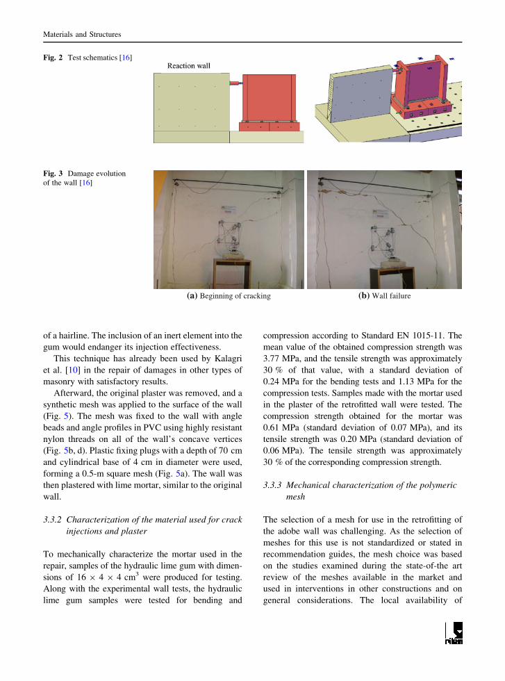
In the first experimental test series, the wall was
subjected to cyclic and dynamic tests [16]. The general
scheme of the test setup is displayed in Fig. 2.
A vertical uniform load with an equivalent mass of
20 kN was added on top of the wall to simulate the
common dead and live loads on typical adobe
structures. A cyclic horizontal demand of increasing
amplitude was applied 2.5 m above the base of the
wall until failure (Fig. 3). The displacement was
applied through a hydraulic actuator, and the values
were registered through transducers, electronic poten-
tiometers and optical fiber sensors.
From the cyclic tests, the maximum lateral force
obtained was 58.14 kN, corresponding to a shear
strength capacity of 57.28 kPa. The maximum drift
imposed was 0.61 % (Fig. 17, under original wall).
The shear strength was determined at the base of the
wall for mean values of the horizontal stress, taking
into consideration the contribution of the wall’s web to
its resistance capacity.
After the first cycle, the wall’s strength registered a
strong decrease, with a notable stiffness reduction.
The failure mode was fragile, as expected for adobe
constructions. An important factor in the decrease in
the strength of a masonry wall is the strength capacity
of the bond between the mortar and adobe blocks.
Maheri et al. [11] have studied the influence of this
particular parameter. In their study, the first fissures
appeared due to the low bonding strength between
mortar and blocks. The initial development of cracks
is mainly in the diagonal direction. Subsequently, for
high loads, the fissures become vertical. However,
research on the bond properties between adobe blocks
and mortar is still limited.
3.3 Damage repair and strengthening solution
3.3.1 Brief description
After the first experimental test series, the wall was
repaired by pressure-injecting hydraulic lime gum into
the cracks (Fig. 4). This gum consisted of a simple
mixture of hydraulic lime diluted in water with no
inert elements, as most of the fissures had the thickness
(a) Initial phase of construction – foundation
(b) Construction development (c) Wall before plastering
(d) Plastering (e) Wall with plaster (f) After air lime application
Fig. 1 Construction phases
Materials and Structures
of a hairline. The inclusion of an inert element into the
gum would endanger its injection effectiveness.
This technique has already been used by Kalagri
et al. [10] in the repair of damages in other types of
masonry with satisfactory results.
Afterward, the original plaster was removed, and a
synthetic mesh was applied to the surface of the wall
(Fig. 5). The mesh was fixed to the wall with angle
beads and angle profiles in PVC using highly resistant
nylon threads on all of the wall’s concave vertices
(Fig. 5b, d). Plastic fixing plugs with a depth of 70 cm
and cylindrical base of 4 cm in diameter were used,
forming a 0.5-m square mesh (Fig. 5a). The wall was
then plastered with lime mortar, similar to the original
wall.
3.3.2 Characterization of the material used for crack
injections and plaster
To mechanically characterize the mortar used in the
repair, samples of the hydraulic lime gum with dimen-
sions of 16 9 4 9 4 cm3 were produced for testing.
Along with the experimental wall tests, the hydraulic
lime gum samples were tested for bending and
compression according to Standard EN 1015-11. The
mean value of the obtained compression strength was
3.77 MPa, and the tensile strength was approximately
30 % of that value, with a standard deviation of
0.24 MPa for the bending tests and 1.13 MPa for the
compression tests. Samples made with the mortar used
in the plaster of the retrofitted wall were tested. The
compression strength obtained for the mortar was
0.61 MPa (standard deviation of 0.07 MPa), and its
tensile strength was 0.20 MPa (standard deviation of
0.06 MPa). The tensile strength was approximately
30 % of the corresponding compression strength.
3.3.3 Mechanical characterization of the polymeric
mesh
The selection of a mesh for use in the retrofitting of
the adobe wall was challenging. As the selection of
meshes for this use is not standardized or stated in
recommendation guides, the mesh choice was based
on the studies examined during the state-of-the art
review of the meshes available in the market and
used in interventions in other constructions and on
general considerations. The local availability of
Fig. 2 Test schematics [16]
(a) Beginning of cracking (b) Wall failure
Fig. 3 Damage evolution
of the wall [16]
Materials and Structures

materials was another requirement. Therefore, inqui-
ries were made regarding the available meshes in the
local market. During the selection, several consider-
ations were taken into account. For instance, adobe
is a material with a high water absorption capacity.
Consequently, and to assure the good performance
and durability of the strengthening material in direct
contact with adobe, any material that can be affected
by corrosion should not be used. Therefore, meshes
that may have corrosion problems were not consid-
ered in the strengthening solution. Other issues were
also taken into account when selecting a mesh to
use, including strength, grid dimension, roughness
and malleability.
(a) Filling of fissures (b) Injection of hydraulic lime
Fig. 4 Damage repair of the wall
(a) Plastic fixing plugs (b) Profiles in PVC
(c) General scheme of the strengthening (d) Application of the synthetic meshsolution
Fig. 5 Strengthening of the
wall
Materials and Structures

The mesh strength should be adequate to provide
good confinement of the adobe wall, with a retrofit of
its properties. The dimensions of the mesh grid should
provide for a good bonding between the wall and
mesh; a grid that is too sparse will reduce the
strengthening feature of the solution, while a grid that
is too dense will not provide for good adhesion.
Concerning the mesh roughness, it is important that
the mesh surface is unpolished to provide a good grip.
The malleability of mesh is quite important, as the
mesh should adjust to the irregularities of the wall. A
polymeric mesh was selected due to its following
characteristics:
– Commercial product with high availability in the
market;
– Low-cost when compared with other available
meshes;
– Non-corrodible;
– No polished exterior texture;
– Opening size of 15 9 20 mm2, which is an area
considered to provide an adequate distribution of
stresses and deformations without making the
plaster difficult to apply;
– Easily flexible, with a small mesh thickness
(0.8 9 0.6 mm2), which can provide a high mal-
leability and good adjustment to all of the wall’s
irregularities.
The selected mesh was subjected to a tensile test to
evaluate its mechanical behavior. The test was con-
ducted at a constant speed of 3 mm/min and at an
average temperature of 22 �C. Two samples were
tested with the same width (18.5 cm) and two different
heights (22.5 and 23.5 cm).
Figure 6 shows the stress versus deformation
results of the tensile tests. The tensile failure tension
is 9 MPa for a maximum longitudinal deformation of
18 %. The initial Young’s modulus was determined by
considering the trend line for the elastic linear portion:
E0 = 150 MPa.
3.4 Tests of the strengthened adobe wall
After repairing and retrofitting the adobe wall, the
strengthened wall was tested using the same test
procedure utilized for the unstrengthened wall. As
discussed in Sect. 3.2, during the dynamic and cyclic
tests, a vertical uniform load was applied to the top of
the wall through an equivalent mass of 20 kN
(Fig. 7a). This load simulates dead loads, such as
timber roofs and floors, or live loads in typical adobe
constructions. For this value, it was considered that the
weight corresponded to a 2.5-m length of timber
formwork (0.50 kN/m2) and to a timber roof with
ceramic tile (0.88 kN/m2). A frieze composed of adobe
with a height of 0.40 m was also considered. The
vertical load on top of the wall did not impose any
restrictions on the boundary condition on top of the
wall.
To estimate the natural frequency of the wall while
the horizontal displacement was applied, a seismo-
graph was placed in a special opening at the top of the
wall that was built for this purpose (shown in Fig. 7a).
After each of the different displacement values was
imposed, the wall was hammered in its main plane
with a rubber hammer, and the resultant accelerations
were registered with the seismograph. These acceler-
ations allowed for the determination of the wall’s first
frequency. The frequencies were also evaluated
through optical fiber accelerometers (Fig. 7b).
The cyclic test was developed by imposing a cyclic
horizontal displacement at a height of 2.5 m from the
base of the wall. The displacement was applied
through a hydraulic actuator with a maximum load
potency of 90 kN (Fig. 7c), and the values were
registered through a load cell type TC4 connected to
the actuator embolus. A steel profile fixed to a thick
timber element was placed between the actuator and
the wall, with the timber element in direct contact with
the wall. The displacements and general response of
the wall during the cyclic horizontal displacement
tests were registered through transducers, electronic
potentiometers and optical fiber sensors (Fig. 7c, e).
The georadar technique was also used to identify
and monitor the evolution of damage at the end of each
cycle. The results obtained with this technique are
Fig. 6 Tensile test results
Materials and Structures

described in detail by Grangeia et al. [8] and Tareco
et al. [19].
3.4.1 Cyclic test
3.4.1.1 Test procedure and instrumentation The
same test procedure used for the original wall was
applied to the retrofitted wall. A cyclic displacement
of increasing amplitude was applied 2.5 m above the
base of the wall until its collapse. As stated before, a
uniform vertical load of 20 kN was also applied to the
top of the wall. Figures 8 and 9 show the position of
the electronic transducers and the point at which the
displacement was imposed, respectively, as in the test
conducted on the original wall.
To enable a better identification and representation
of the fissures formed during the tests, a square grid of
dots with a 0.25-m spacing was placed on one side of
the wall. This grid was extremely useful for rigorously
representing the position and propagation of the cracks
during the tests.
3.4.1.2 Test results The retrofitted wall was
cyclically tested with horizontally controlled
displacements. The consecutive drift amplitudes
imposed on the wall are shown in Table 4. For each
amplitude step of imposed lateral drifts, the cyclic
displacements were repeated three times.
Figure 10 shows the force cycles applied to the wall
during the tests. It is possible to observe the force
peaks registered for the wall, portraying its response
capacity to the imposed drifts.
From these results, the lateral displacements profile
evolution can be obtained (Fig. 11). The drift is
computed by dividing the imposed displacement by
the wall’s height. In the first horizontal cycle (until
0.1 % drift), the deformed shape of the wall had a
rather linear behavior. In the final phase of the tests
(for high drifts), the wall showed a strong non-linear
behavior (after a drift of 0.5 %).
No sliding occurred at the base of the wall, as the
sensor fixed to the wall did not register any displace-
ments during the displacement cycles.
(a) Vertical load and (b) Optical fiber sensors (c) Hydraulic actuator
(d) Electronic transducers (e) Optical sensors (f)
seismograph
Georadar equipment
Fig. 7 Equipment used in the tests
Materials and Structures

Based on the wall response to the rising amplitude
displacements, the following observations were made
(Fig. 12):
– The maximum shear strength of the wall was
approximately 70.69 kPa, corresponding to a force
of 71.75 kN.
– The shear resistance obtained at a drift of 1 % was
approximately 45 kPa (70 % of the maximum
shear strength of the wall).
– The maximum imposed deformation was 1.6 %
for a corresponding displacement of 45 mm.
– During the first few cycles, the wall response was
almost linear, although some small cracking
occurred.
Figure 13 shows the graphs obtained for the
moment at the base of the wall versus rotation close
to the displacement application point (h = 2.5 m).
The results obtained were analyzed, and the following
conclusions were drawn:
– The maximum moment at the wall base was 180
kNm.
– There is a moment strength degradation of
approximately 25 % in the last few cycles (135
kNm).
– In the first few cycles, a quasi-linear behavior
was observed in the curve moment versus
rotation at the wall’s base (until a rotation of
0.15 mrad).
– In the last cycle (drift of 1.6 %) in the west-east
orientation, the maximum rotation was observed in
the two control sections.
(a) Vertical displacement transducers (b) Horizontal displacement transducers
Fig. 8 Displacement transducers on the west and east faces of the wall
Fig. 9 Displacement transducers on the north face of the wall
-80
-60
-40
-20
0
20
40
60
80
For
ce (
kN)
Step
Fig. 10 Evolution of force on the wall during the cyclic tests
Table 4 Imposed lateral drift of the wall
Drift (%)
0.005 0.01 0.02 0.05 0.1 0.2 0.5 1.0 1.6
Materials and Structures

– The fissures began at a base rotation of 0.15 mrad
and a rotation of 0.80 mrad at a height of 2.40 m.
– In the cycle with base rotations of 0.4 and 2 mrad at
a height of 2.40 m, the diagonal cracking exhibited
larger openings than in previous cycles, with
plaster detachment in certain areas.
The evolution of the dissipated energy during the
test was determined by integration of the force
displacement chart (Fig. 14).
Four distinct levels of dissipated energy were
identified:
– In the first few cycles of imposed deformation,
there was almost no energy dissipation, confirming
the absence of damage at this level.
– The energy dissipation began at drifts ranging
from 0.02 to 0.2 %, indicating the initiation of
damage and crack propagation in the wall.
– At a drift of 0.5 %, there was a more intense
damage evolution.
– In the last few cycles, during which high defor-
mations were imposed, the amount of damage to
the wall increased exponentially, as shown in the
energy dissipation graph. Approximately 4/5 of
the total energy was dissipated at this time.
Based on an analysis of the results, the fissures
began at a deformation of 0.05 %. By increasing the
deformation amplitude in the following cycle, cracks
that had already formed began to rapidly propagate.
Furthermore, new cracks with larger openings and
more rapid development were observed. In the follow-
ing displacements, an intense detachment of the plaster
was observed in the cracked area. Local crushing in the
area where the displacement was imposed was also
observed. Figures 15 and 16 show a detailed graphical
representation of the wall response during the tests.
3.4.2 Dynamic tests
The assessment of the natural frequency of a structure
and its progression over time is important for under-
standing the behavior of structures and their corre-
sponding damages in the structure. As mentioned
previously, a seismograph was placed on top of the
wall to evaluate the frequency evolution. With this
instrument, a signal can be obtained from an excita-
tion, allowing for the determination of the natural
frequency of the structure.
During the cyclic tests, the natural frequency was
measured for each cycle to relate the frequencies with
the damages on the wall during several cycles of
First few cycles(b)Entire test(a)
F d
2.50m
F d
2.50m
θ θ
Fig. 12 Cyclic response in terms of force versus drift
0
1
2
3
0 5 10 15 20 25
Hei
ght (
m)
Lateral displacement (mm)
Drift of 0.1% Drift of 0.2%
Drift of 0.5% Drift of 1.0%
Fig. 11 Lateral displacement profile
Materials and Structures

imposed deformations. The results obtained are shown
in Fig. 18.
3.5 Efficiency of the repair and strength solution
To evaluate the efficiency of the retrofit solution, a
force-drift graph was built based on the results of the
original wall and the retrofitted wall. With this graph,
the wall responses before and after strengthening can
be compared.
From Fig. 17, the following conclusions are drawn:
– After performing the repair and strengthening of
the wall, its stiffness improved and became
equivalent to that of the original wall.
– The maximum resistant shear capacity of the wall
increased by 23.43 % after the retrofit.
– The maximum deformation of the wall tripled after
the retrofit.
– The fragility of the wall decreased after the peak
force was reached, thereby increasing its ductility
and energy deformation capacity.
– In consecutive cycles, a lesser degradation of
resistance was observed in the retrofitted wall.
The efficacy of both the wall repairs and the
strengthening measures was also evaluated based on
the values of the wall’s natural frequency before the
horizontal displacements were imposed in both the
original and reinforced states. These frequencies for
both test sets were analyzed in a comparison graph
(Fig. 18) to obtain a better characterization of the
damage evolution.
By analyzing the values obtained for the natural
frequency before and after retrofitting, it is clear that
the strengthening procedure allowed the original
stiffness of the undamaged wall to recover. The first
frequency presented in the graph corresponds to the
wall frequency before the cyclic tests began. From the
graph, it can be observed that the response of the
retrofitted wall had a smoother stiffness decrease and
thus a smoother natural frequency decrease compared
with the original wall. Thus, from these results, it is
possible to conclude that the repair and strengthening
procedures implemented in this study are beneficial
for the enhancement of wall behavior when subjected
to horizontal demands.
In summary, it can be stated that the repair and
strengthening solution implemented on the adobe wall
increased the wall’s maximum resistance by 23.43 %
and increased its maximum drift by 220 %.
Regarding adobe construction in general, as the
geometry and material characteristics of these con-
structions and their reinforcements vary, a direct
comparison of the results of the present study with
those in the literature is not feasible. Nevertheless, it is
possible to perform a comparison with respect to
percentage gains due to the utilization of mesh
reinforcements with the results of Blondet et al. [2],
who performed a similar study. In their study, the
0
2
4
6
8
10
12
Dis
sipa
ted
ener
gy (
kN.m
) Δ(%)=0.005 - 0.01
Δ(%)=0.02 - 0.2
Δ(%)=0.5
Δ(%)=1.0 - 1.6
Step
Fig. 14 Evolution of energy dissipation
(a) Base rotation
-200
-150
-100
-50
0
50
100
150
200
-1.2 -0.8 -0.4 0 0.4 0.8 1.2
Bas
e m
omen
t (kN
.m)
Base rotation (mrad)
M
(b) Rotation at a height of 2.45 m
-200
-150
-100
-50
0
50
100
150
200
-10 -5 0 5 10
Bas
e m
omen
t (kN
.m)
Top rotation (mrad)
M 2.45m
θ θ
θ θ
Fig. 13 Response in terms of moment versus rotation
Materials and Structures

resistance and drift increased by 2.63 and 100 %,
respectively, which corresponds to lower values than
those obtained in the present study.
4 Main conclusions and final comments
In the initial part of this research on the development
of repair techniques, it was possible to conclude that
some of the types of damage typically found in adobe
constructions can be easily repaired through simple
and inexpensive rehabilitation techniques. To study
the behavior of adobe constructions and develop
inexpensive techniques for their retrofitting, a real-
scale adobe wall was built and tested under cyclic
horizontal loads. Then, a strengthening solution was
applied, and the strengthened wall was tested. This
study provides information that contributes to the
understanding of the behavior of adobe masonry
structures under cyclic loads, such as those induced by
earthquakes.
All of the materials used for the construction, repair
and strengthening of the wall were tested in the
laboratory. The preparation of all of the materials and
the retrofitting of the wall were all conducted in the
laboratory; thus, all of the materials and techniques
used were rigorously controlled. The materials used in
the wall retrofit were inexpensive and proved to be
efficient in the improvement of the wall performance.
The tests performed in this study demonstrated that,
with the retrofit that was implemented, the stiffness of
an adobe wall could be recovered, with a triple
increase in the ductility, a significant improvement in
the energy dissipation and a 23.43 % increase in the
wall’s shear capacity. In addition, after the retrofitting,
no fragile ruptures were observed, although this type
of failure is typical in this type of masonry. The
strengthening solution was able to improve the
S
0,25
0,50
0,75
1,00
1,25
1,50
1,75
2,00
2,25
2,50
2,75
3,00
N
0,25
0,50
0,75
1,00
1,25
1,50
1,75
2,00
2,25
2,50
2,75
3,00
= 0.05%Δ = 0.10%•
Fig. 15 Damage evolution in the south and north faces of the wall
Materials and Structures

structural performance of the wall, thereby decreasing
its seismic vulnerability. With the results obtained, it
was possible to conclude that the effects due to seismic
actions can be significantly reduced when these adobe
structures are adequately reinforced.
The inexpensive repair and strengthening solution
used on the wall were able to increase the maximum
resistance and maximum drift by 23.43 and 220 %,
respectively. These remarkable improvements suggest
S
0,25
0,50
0,75
1,00
1,25
1,50
1,75
2,00
2,25
2,50
2,75
3,00
N
0,50
0,75
1,00
1,25
1,50
1,75
2,00
2,25
2,50
2,75
3,00
Plaster detaching
Cracks in the adobe blocks
Fig. 16 Final damage state: south and north faces
-80
-60
-40
-20
0
20
40
60
80
-2 -1 0 1 2
For
ce (
kN)
Drift (%)
Original wall
Strengthened wall
Fig. 17 Comparative response of the original (non-strength-
ened) and strengthened walls in terms of force versus drift
0
5
10
15
20
25
0 0,2 0,4 0,6 0,8 1 1,2 1,4 1,6
Fre
quen
cies
(H
z)
Drift (%)
Strengthened wall
Original walll
Fig. 18 Natural frequency evolution of the original and
strengthened adobe walls
Materials and Structures

that this solution can be used effectively by construc-
tion and rehabilitation companies in the preservation
and strengthening of these structures.
Acknowledgments The authors of this paper would like to
express their deepest thanks to all of the people, companies and
institutions that allowed this research to be pursued by helping
with the preparation and development of the experimental tests,
including the Laboratory of Earthquake and Structural
Engineering (LESE), Faculty of Engineering, Porto
University; STAP; Fregaze; Aveiro City Council; and the
Physics, Mechanical and Geological Sciences Departments of
Aveiro University, all of which are located in Portugal.
References
1. Blondet M, Garcia G, Brzey S (2003) Construcciones de
adobe resistentes a los terremotos. Contribution for ‘‘World-
Housing Encyclopedia’’, Marjorie Greene, EERI/IAEE
2. Blondet M, Torrealva D, Garcia G, Ginocchio F, Madueno I
(2005) Using industrial materials for the construction of safe
adobe houses in seismic areas. In: EarthBuild2005 Inter-
national Conference, University of Technology. Sydney,
Australia
3. Corazao M, Blondet M (1973) Estudio Experimental del
Comportamiento Estructural de las Construcciones de
Adobe Frente a Solicitaciones Sısmicas. Banco Peruano de
los Constructores. Departamento de Ingenieria, Universidad
Catolica del Peru, Lima, Peru
4. Costa A, Varum H, Pereira H, Rodrigues H, Vicente R,
Arede A, Costa AA (2007) Avaliacao experimental do
comportamento fora do plano de paredes de alvenaria de
adobe. V Seminario Arquitectura de Terra em Portugal,
Departamento de Engenharia Civil, University of Aveiro,
Aveiro, Portugal
5. Costa A, Varum H, Arede A, Costa AA, Pereira H, Silveira
D, Rodrigues H, Vicente R (2008) Caracterizacao do com-
portamento estrutural de adobes e de paredes de alvenaria de
adobe. Portuguese Journal ‘‘Revista Construir’’, Workme-
dia, Ano V, Numero 123, pp 22–25
6. Fernandes M, Mestre V (2006) Portugal atlantico versus
Portugal mediterraneo – tipologias arquitectonicas em terra.
International Conference TerraBrasil 2006, Ouro Preto,
Minas Gerais
7. Figueiredo A (2009) Caracterizacao de uma solucao de
reforco sısmico de paredes de adobe. Civil Engineering
Master Degree dissertation, Civil Engineering Department,
Aveiro University, Aveiro
8. Grangeia C, Tareco H, Senos-Matias M, Varum H, Costa A
(2010) Utilizacao de georadar na caracterizacao da evol-
ucao do dano estrutural de uma parede: ensaio a escala real.
8th National Conference on Seismology and Earthquake
Engineering, Sısmica 2010, Universidade de Aveiro, Aveiro
9. Houben H, Guillaud H (1994) Earth Construction—a
Comprehensive guide, CRATerre – EAG. Intermediate
Technology Publications, London
10. Kalagri A, Miltiadou-Fezans A, Vintzileou E (2010) Design
and evaluation of hydraulic lime grouts for the
strengthening of stone masonry historic structures. Mater
Struct 43:1135–1146
11. Maheri M, Motielahi F, Najafgholipour MA (2011) The
effects of pre and post construction moisture condition on
the in-plane and out-of-plane strengths of brick walls. Mater
Struct 44:541–559
12. Martins T, Varum H (2006) Adobe’s mechanical charac-
terization in ancient constructions: the case of Aveiro’s
region. Mater Sci Forum 514–516:1571–1575
13. Minke G (2006) Building with earth, design and technology
of a sustainable architecture. Birkhauser—Publishers for
Architecture, Basel-Berlin-Boston, ISBN-10: 3764374772
14. Mohammed A, Hughes TG (2011) Prototype and model
masonry behavior under different loading conditions. Mater
Struct 44:53–65
15. Noguez R, Navarro S (2005) Reparacion de muros de adobe
com el uso de mallas sinteticas. PUCP, International Con-
ference SismoAdobe2005
16. Pereira H (2008) Caracterizacao do comportamento estru-
tural de construcoes em adobe. Civil Engineering Master
Degree dissertation, Civil Engineering Department, Aveiro
University, Aveiro
17. Silveira D, Varum H, Costa A (2007) Rehabilitation of an
important cultural and architectural heritage: the traditional
adobe constructions in Aveiro district. In: Kungolas A,
Brebbia CA, Beriatos E (eds) Sustainable development.
WITPress, Carvoeiro, Algarve, pp 705–714. ISBN 978-1-
84564-103-0
18. Silveira D, Varum H, Costa A, Martins T, Pereira H,
Almeida J (2012) Mechanical properties of adobe bricks in
ancient constructions. Constr Build Mater 28(1):36–44. doi:
10.1016/j.conbuildmat.2011.08.046
19. Tareco H, Grangeia C, Varum H, Senos-Matias M (2009) A
high resolution GPR experiment to characterize the internal
structure of a damaged adobe wall. EAGE First Break
27(8):79–84
20. Torgal P, Jalali S (2009) Construcao em Terra: o Passado,
Presente e o Futuro – Revista Profissional da construcao.
National Journal Arte &Construcao, N. 230 – Portugal
21. Vargas J, Blondet M, Ginocchio F, Garcıa G (2005) 35 Anos
de investigaciones en sismo adobe: la tierra armada, Inter-
national Conference SismoAdobe 2005: Architecture,
Construction and Conservation of Earthen Buildings in
Seismic Areas, Lima, Pontificia Universidad Catolica del
Peru,. Lima, Peru
22. Varum H, Martins T, Velosa A (2005a) Caracterizacao do
adobe em construcoes existentes na regiao de Aveiro. Ibe-
rian-American Conference, IV SIACOT Seminario Ibero-
Americano de Construcao com terra e III Seminario Ar-
quitectura de Terra em Portugal. Convento da Orada.
Monsaraz, Portugal
23. Varum H, Costa A, Pereira H, Almeida J, Rodrigues H
(2006a) Avaliacao Experimental do Comportamento
Estrutural de Elementos Resistentes em Alvenaria de Adobe
- III Congreso Internacional de Arquitectura en Tierra:
Tradicion y Innovacon - Universidad de Valladolid, Valla-
dolid, Espana, 11 a 12 de Agosto de 2006
24. Varum H, Costa A, Pereira H, Almeida J (2006b) Com-
portamento estrutural de elementos resistentes em alvenaria
de adobe. International ConferenceTerra Brasil. Minas
Gerais. Ouro Preto, Brazil
Materials and Structures

25. Varum H, Costa A, Velosa A, Martins T, Pereira H,
Almeida J (2006c) ‘‘Caracterizacao mecanica e patologica
das construcoes em Adobe no distrito de Aveiro como su-
porte em intervencoes de reabilitacao’’ - Projecto Culture
2000/Mediterrae - Houses and cities built with earth: con-
servation, significance and urban quality. ARGUMEN-
TUM, Junho de 2006, pp 41–45, ISBN 972-8479-41-7
26. Varum H, Figueiredo A, Silveira D, Martins T, Costa A
(2011) Outputs from the research developed at the Univer-
sity of Aveiro regarding the mechanical characterization of
existing adobe constructions in Portugal - Revista Informes
de la Construccion 63(523):127–142. doi:10.3989/ic.10.016
27. Veiga O, Galhano F (1992) Arquitectura Tradicional Por-
tuguesa. Portugal de Perto Publicacoes D. Quixote, Portugal
28. Yamin L, Phillips C, Reyes J, Rivero S, Ruiz D (2007)
Estudios de vulnerabilidad sısmica, rehabilitacion y refu-
erzo de casas en adobe y tapia pisada. Revista de Estudios
sobre Patrimonio. J Cult Heritage Stud, ISSN 1657-9763
29. Zavala C, Igarashi L (2005) Propuesta de Reforzamiento
para Muros de Adobe. In: International Conference Sis-
moAdobe 2005: architecture, construction and conservation
of earthen buildings in seismic areas. Lima, Pontificia
Universidad Catolica del Peru, Lima, Peru
Materials and Structures