Embed Size (px)
Citation preview

GEOPHYSICS, VOL. 63, NO. 4 (JULY-AUGUST 1998); P. 1285–1294, 11 FIGS., 1 TABLE.
Seismic reflection imaging of a geothermal aquiferin an urban setting
Lee Liberty∗
ABSTRACT
A seismic reflection survey that was conducted indowntown Boise, Idaho, to help city planners site a newwell for injection of spent geothermal water illustratessome methods to safely and successfully employ a seis-mic reflection survey in an urban setting. The objectiveof the seismic survey was to estimate the depth and con-tinuity of a basalt and rhyolite volcanic sequence. Wellsiting was based on geothermal aquifer depth, location ofinterpreted faults, projected thermal impact of injectionon existing wells, surface pipe extension costs, and pub-lic land availability. Seismic acquisition tests and carefulprocessing were used to ensure high-quality data whileminimizing the potential for damage along city streets.A video camera placed in a sewer and a blast vibrationmonitor were used to confirm that energy from the seis-mic source (a 75-in3 land air gun) did not damage nearby
buildings, street surfaces, or buried utilities along thesurvey lines. Walkaway seismic tests were also used tocompare signal quality of the air-gun source to an explo-sive source for imaging targets up to 800 m depth. Thesetests show less signal bandwidth from the air-gun sourcecompared to the buried explosive source, but the air-gunsignal quality was adequate to meet imaging objectives.
Seismic reflection results show that the top of this rhy-olite/basalt sequence dips (∼8–11◦) southwest away fromthe Boise foothills at depths of 200 to 800 m. Seismicmethods enabled interpretation of aquifer depths alongthe profiles and located fault zones where injected watermay encounter fracture permeability and optimally ben-efit the existing producing system. The acquisition andprocessing techniques used to locate the Boise injectionwell may succeed for other hydrogeologic and environ-mental studies in urban settings.
INTRODUCTIONThe first geothermal heating district in the nation was es-
tablished in Boise, Idaho, in 1892 (Wood and Burnham, 1987).Today, over 100 million gal of water are drawn annually fromwells into the geothermal aquifer to provide heat to govern-ment buildings and residential homes in Boise through a dis-tribution of more than 10 km of surface pipes (Rafferty, 1992).Four separate geothermal-based heating facilities are presentlyin operation (Figure 1), including the Boise Warm Springs Wa-ter District, the State of Idaho, the U.S. Department of VeteransAffairs, and the City of Boise systems.
In recent years, the increased rate of hot water extrac-tion has resulted in a drop in artesian levels. The Idaho De-partment of Water Resources has imposed a moratorium onincreased production from the geothermal aquifer until ac-tions are taken to stabilize the system. Since the Depart-ment of Veterans Affairs and the State of Idaho already injectspent geothermal water, and the Boise Warm Springs Water
Manuscript received by the Editor April 17, 1997; revised manuscript received September 26, 1997.∗Center for Geophysical Investigation of the Shallow Subsurface (CGISS), Boise State University, Boise, Idaho 83725. E-mail: [email protected]© 1998 Society of Exploration Geophysicists. All rights reserved.
District has legal rights to the geothermal aquifer without in-jection of spent water (based on a historical precedent), theCity of Boise and the U.S. Department of Energy have agreedto design and construct a new injection well.
To continue to develop the Boise geothermal aquifer, stepsmust be taken to stabilize the pressure of the system withoutsignificantly reducing the temperature of the extracted water.However, with the current practice of dumping spent geother-mal water into the Boise River and extracting water faster thannatural recharge, the system’s ability to stabilize is greatly re-duced. In addition, the spent geothermal water has a high flu-oride (∼15 ppm) and thermal load. Limitations on dumpingthe unprocessed water directly into the river may soon be set.By adding a new injection well, the city hopes to stabilize thegeothermal system and lift the moratorium imposed by theIdaho Department of Water Resources, thereby allowing morecustomers to have access to this potentially renewable and localenergy resource.
1285

1286 Liberty
Two seismic reflection lines (Figure 1) were deployed to helpsite the new geothermal injection well. Since the footage costsfor drilling match the footage costs for extending the pipesfor the heating system, seismic line locations were chosen tocover an area near the existing collection and distribution sys-tem and near well control, thus placing the seismic reflectionprofiles in downtown Boise. A first-order goal was to estimatethe depth to the geothermal aquifer along the profiles so thatdrilling costs associated with different sites could be identi-fied. In addition to estimating depth to the geothermal aquifer,locating faults in the rhyolite/basalt sequence was of interest.If the injection well penetrates a fault zone, the geothermalwater may circulate back to the production wells, assuming thefaults act as conduits for geothermal water circulation. Also, arequirement that the injection well minimize the thermal im-pact on the existing production wells forced the new injectionwell site south of the current production field (Figure 1). Theideal site, from the city’s perspective, was at the present spentgeothermal water disposal site along the Boise River (Figure 1),where infrastructure and appropriate zoning already exist, butfinal site selection considered drilling costs (based on aquiferdepth), surface pipe extension costs, land availability, thermalimpact on the existing well field, and geometry of the geother-mal aquifer (i.e., fault locations).
GEOLOGIC FRAMEWORK
Each geothermal production well in Boise pumps 65–75◦Cwater from a porphyritic rhyolite member of the Idavada
FIG. 1. Location map of study area in downtown Boise, Idaho. Seismic reflection line locations, walkaway test sites, Boise Citygeothermal pipes, and geothermal wells are identified. Asterisk along Line 1 represents selected injection site.
Group, an upper Miocene volcanic and sedimentary rock as-semblage (Figure 2). The rhyolite units are widespread andare suspected to extend throughout much of the Boise val-ley (Wood and Burnham, 1983; Clemens and Wood, 1993).The geometry of permeability in the rhyolite unit is unknown.Fracture permeability as a result of original cooling joints, flowbreccia, or weathering is suspected in some wells (e.g., Stateof Idaho wells), whereas fractures related to faults may con-tribute to geothermal water circulation in other productionwells (e.g., Boise city wells, Veterans Administration wells).Wedge-shaped fault blocks mapped along the Boise front ex-ist as a result of late Cenozoic normal faulting (Wood andBurnham, 1983). These interconnected faults, ranging from aN10◦W to N70◦W orientation, provide potential avenues forlateral and vertical geothermal water circulation within thevolcanic units.
The geothermal water is confined from above by a basalt,basaltic tuff, and sedimentary rock sequence. In particular, low-permeability basaltic tuffs unconformably overlie the erodedtop of the geothermal aquifer (Clemens and Wood, 1993).The upper contact to the geothermal system can be recog-nized by both a temperature and a static water-level increasein geothermal wells at the lower contact of the basaltic tuffs(Wood and Burnham, 1983). Miocene to Quaternary IdahoGroup fluvial and lacustrine sediments unconformably over-lie the basaltic tuffs and fill the western Snake River PlainBasin (Wood, 1994). Beneath the Boise downtown area, thedeeper Idaho Group sediments are predominantly lacustrine

Seismic Imaging in an Urban Setting 1287
mudstones of low permeability overlain by fluvial interbeddedsands, muds, and gravels (S. Wood, personal communication).The deeper Idaho Group sediments contain two intercalatedbasalt flows (Clemens and Wood, 1993).
Below the rhyolite units are granitic rocks of the CretaceousIdaho Batholith. Fractures in the Idaho Batholith rocks arethe presumed avenue for deep circulation and natural rechargeof the aquifer (Figure 3). Open fractures from late Cenozoicfault activity are a conduit for the hot water, with a moderateartesian head, into the permeable rhyolite units above (Woodand Burnham, 1983).
SEISMIC METHODS
Walkaway seismic tests
A surface seismic source was needed to acquire seismic datathrough downtown Boise because of restrictions on shot-holedrilling along city streets underlain by utilities. We selected aland air gun (from Bolt Technologies) as our seismic source be-cause of its mobility, repeatability, and energy output. A sweptseismic source (e.g., vibroseis or MiniSOSIE) was not selectedbecause the required signal durations exceeded the recordingcapabilities of our system. We compared the air gun’s energyoutput with a buried explosive source (1/3 lb kinestik) to de-termine if the signal quality of the air gun was adequate to im-age our target. We selected two walkaway test sites (Figure 1)at geologic end-member locations (where estimated bedrockdepth was shallowest and deepest along the proposed pro-files). Bedrock depths were projected from nearby geothermalwells (Figure 2) and estimates of dip for the volcanic assem-blage. Results from the test site with greatest depth to bedrock
FIG. 2. Geologic cross section through downtown Boise based on local geothermal wells (from Burnham and Wood, 1985). Thesection has equal horizontal and vertical scales. The site for the Fort Boise walkaway seismic test is shown.
(Figure 4a) show a large-amplitude reflection package nearthe predicted depth to the top of the rhyolite/basalt sequenceusing the explosive and the air-gun sources. Although reflec-tions from the air-gun source appear more band limited (Fig-ure 4b), comparable reflections appear. Thus, the results ofthe walkaway tests indicate that both the explosive and theair-gun sources provided enough energy to image the rhyo-lite/basalt sequence at the end-member sites. The results alsosuggest that the projected depth to the upper rhyolite at theinitially preferred injection site (at the present disposal siteshown on Figure 1) was too deep (based on the assumptionthat the thickness of the upper rhyolite to upper basalt con-tact is constant, as shown in Figure 2). Depth to the rhyolite atthe site is greater than 800 m (using 2100 m/s velocity). Thatdepth, and the uncertainty of the thickness of section used toextrapolate the rhyolite aquifer below the basalt reflector, ledto the abandonment of the original site north of the Boise River(Figure 1).
Damage tests
Boise city officials and local utility representatives requiredproof that no damage to city streets, buried utilities, or adja-cent buildings would result from acquiring seismic data with aland air gun. Also, the noise component of the air gun wasof concern due to off-hours acquisition through residentialneighborhoods. The city selected a test site on a street whereroad resurfacing was scheduled and a cracked sewer line wasburied at a depth of 1–2 m. Tests on unlined asphalt and con-crete sidewalks (without a subbase) were also performed. Thecity ran a video camera in the sewer line, both before and afterair-gun shots, to monitor any changes in the sewer’s cementwall. A four-component (longitudinal, transverse, vertical, and

1288 Liberty
FIG. 3. Conceptual model (vertical and horizontal scales approximately equal) representing the local geothermal groundwatercirculation system (modified from Wood and Burnham, 1987). Groundwater circulates through fractures in granite of the IdahoBatholith. Artesian pressure forces the geothermal water along zones of weakness (faults) until it is trapped by impermeable basaltoverlying the permeable rhyolite units.
FIG. 4. (a) Comparison of buried explosive versus land air gun sources at Ann Morrison Park. Both sources produce adequateenergy to image the target zone (up to 800 m depth). (b) Spectral analyses show the buried explosive source produces a broaderreflection bandwidth than the air gun source. The frequency measurements are from a 400–850 ms window at 380–480 m offset.

Seismic Imaging in an Urban Setting 1289
sound) blast vibration monitor was also used to measure peakparticle velocities and sound pressure at various offsets fromthe air gun (Figure 5). These measurements were then com-pared to damage and noise level studies (Bollinger, 1971;Siskind et al., 1980; Konya and Walter, 1990) to assess the riskof structural damage to nearby buildings, buried objects, andthe road surface (Figure 6). We tested the air gun at varyingpressures (1500 and 2000 psi), chamber sizes (60 and 75 in3
guns), and distances from the sewer line.The tests demonstrated that little to no damage on road-
grade asphalt resulted after 2–4 consecutive air-gun shots (withthe 75-in3 chamber), but small cracks appeared after 1–2 shotson unlined asphalt, concrete roadways, and sidewalks. We ob-served no change in the integrity of the sewer line with anycombination of acquisition parameters, including the use of a75-in3 chamber with full pressure (2000 psi) directly over thecracked line at the shallowest site (1 m depth). The results ofthe blast vibration monitor suggest that the air gun could besafely deployed at distances as close as 5 m without proba-ble damage to nearby structures. This was based on observedfrequency and amplitude measurements of the peak particlevelocity (Figure 6). Although frequencies decrease with in-
FIG. 5. Results from the blast vibration monitoring test. Note peak particle velocities (PPV) less than 1 in/s for all three components(longitudinal, transverse, and vertical) and frequencies exceeding 40 Hz at near offsets (5 m). Sound levels fall below any potentialdamage levels for distances greater than 5 m (Bollinger, 1971).
creasing distances from the source (thus increasing the damagerisk), particle velocity amplitudes also decrease. For distancesof 5 m, frequencies greater than 40 Hz were observed, placingdamage probabilities below minor damage levels (Figure 6).Because particle velocities generally increase by a factor ofthree when distance is halved (Konya and Walter, 1990), wechose to maintain a conservative 5 m distance from any per-manent structures or buried utilities with two air-gun shots perlocation (to reduce risk of surface cracking). Empirical studies(Bollinger, 1971) rate this distance as noticeable to unpleasantwith respect to ground motion and sound pressure levels, butthe air-gun source was generally operated at distances greaterthan 10 m from residential buildings and continually moving,therefore maintaining the curiosity of nearby residents withoutgenerating complaints.
Seismic data acquisition
After the walkaway and damage tests successfully demon-strated that the seismic reflection technique could determinedepth to rocks associated with the geothermal aquifer withindowntown Boise, two seismic reflection lines were acquired

1290 Liberty
(Figure 1) to determine the geologic structure. A 10-m sourceand receiver interval was selected to image within the reflectionwindow for the estimated range of aquifer depths (from Fig-ures 2 and 4) and to reduce the influence of ground roll energyon the final stack. Standard common midpoint acquisition tech-niques (Mayne, 1962) for shallow targets (e.g., Hunter et al.,1984; Steeples and Miller, 1990) were employed. At each shotpoint, 8 to 16 air-gun shots were recorded using a source array(moving the air-gun source one pad length after two shots). In-dividual shots records were summed for each station locationto attenuate ambient noise (traffic, wind noise, etc.), groundroll, and increase the overall data quality.
The data were recorded using a 48-channel Bison 9048 seis-mograph with 10-Hz geophones. We selected 10-Hz geophonesbecause of the relatively low-frequency nature of the air-gunsource and the dynamic range of the Bison seismograph. Sand-bags were placed on all geophones to further attenuate air-coupled noise and to help alert on-coming traffic to the geo-phone locations. Baseplates replaced spikes to couple withthe asphalt surface. Shots were recorded on all stations ex-cept across the busiest streets. This provided nearly full 24-foldcoverage along the length of both profiles.
FIG.6. (a) A comparison of particle velocity with damage prob-ability for frequencies greater than 40 Hz. (b) Damage criteria.Note: (from Figure 5) frequency content for near offsets (5 m)is greater than 40 Hz for all components. Figure is modifiedfrom Siskind et al. (1980).
Seismic data processing
The data were checked for quality each day during andafter field acquisition. Data were processed (summarized inTable 1) on a workstation using Landmark’s ProMAX seis-mic processing package. Individual air-gun shots were summedinto common shot gathers using an alpha-trimmed mean sum-ming method. This method excluded 12.5% of the smallest andlargest samples from individual shots and was preferred overa simple shot averaging process because of the large amountof ambient noise. Also, the alpha-trimmed method was su-perior to a diversity stack method (scaling by the inverse ofthe power) because of problems associated with our roll-alongswitch. Because of a wiring short, groups of channels droppedwere occasionally on the raw shot records, thus providing verysmall amplitude signals on these channels. A diversity stackmethod would have amplified the dropped channels by an in-verse scaling process, thus destroying the data quality for anentire common-shot record.
After stacking common-shot gathers, the data were pro-cessed to optimize the signal quality and remove coherent andrandom noise. Muting was applied to reduce surface waves,refractions, and waveguide reverberations. Trace edits, a band-pass filter, and spiking deconvolution also helped improve thesignal quality. An iterative approach to velocity analyses andresidual static corrections increased reflection coherency onthe final stacks. Migration of the stacked seismic data was suc-cessful where full coverage was available. Artifacts from themigration process appeared where data quality suffered fromacquisition and processing limitations.
Reflection line 1
Line 1 begins south of the Boise River on the campus ofBoise State University (Figure 1). The survey line crosses JuliaDavis Park, then follows 3rd Street through downtown Boisebefore terminating at the city’s geothermal production wells.The state’s injection well and the U.S. Geological Survey’s mon-itoring well provide a tie to lithology along the profile.
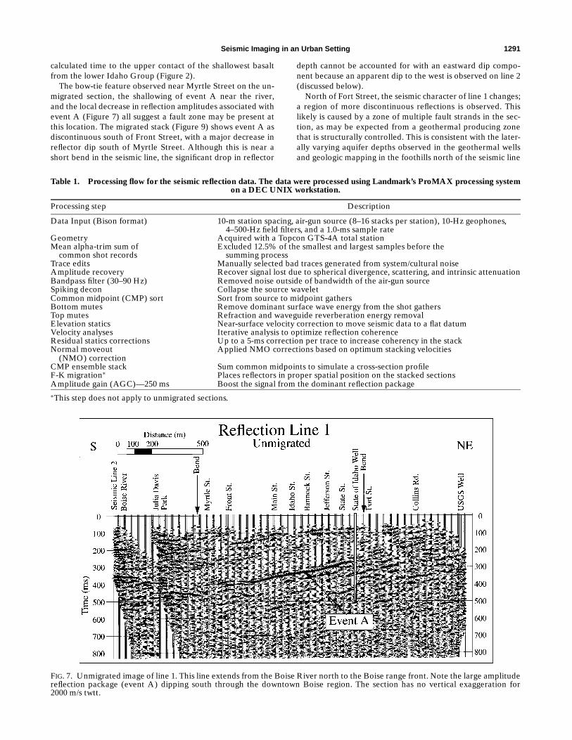
The dominant feature on the unmigrated stack of line 1 (Fig-ure 7) is a reflection that dips (∼11◦) to the south, from 250to 400 ms two-way traveltime (twtt) between Myrtle Streetand Fort Street (event A). South of Myrtle Street, event Acontains lower relative amplitudes, then dips north below JuliaDavis Park with a bow-tie feature (crossing reflections) nearthe bend in the seismic line between Myrtle Street and thepark. Event A shallows to the south near the Boise River andthe line 2 intersection. North of Fort Street, reflections appearmore discontinuous to absent, including event A. Additionalreflections appear in the unmigrated seismic section both aboveand below event A throughout the section, but generally ap-pear more discontinuous. The dip of these secondary reflectorsis generally similar to event A.
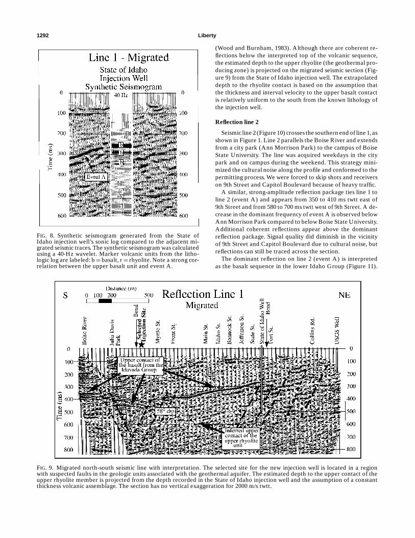
A sonic log from the State of Idaho’s geothermal injec-tion well (along line 1) provides information to build a syn-thetic seismogram (Figure 8) to correlate lithology to the mi-grated seismic section. The expected arrival times of syntheticreflections from individual volcanic units associated with thegeothermal aquifer match the observed arrivals. In particular,event A at the injection well site appears at approximately260 ms twtt on the migrated seismic section and matches the
Seismic Imaging in an Urban Setting 1291
calculated time to the upper contact of the shallowest basaltfrom the lower Idaho Group (Figure 2).
The bow-tie feature observed near Myrtle Street on the un-migrated section, the shallowing of event A near the river,and the local decrease in reflection amplitudes associated withevent A (Figure 7) all suggest a fault zone may be present atthis location. The migrated stack (Figure 9) shows event A asdiscontinuous south of Front Street, with a major decrease inreflector dip south of Myrtle Street. Although this is near ashort bend in the seismic line, the significant drop in reflector
Table 1. Processing flow for the seismic reflection data. The data were processed using Landmark’s ProMAX processing systemon a DEC UNIX workstation.
Processing step Description
Data Input (Bison format) 10-m station spacing, air-gun source (8–16 stacks per station), 10-Hz geophones,4–500-Hz field filters, and a 1.0-ms sample rate
Geometry Acquired with a Topcon GTS-4A total stationMean alpha-trim sum of Excluded 12.5% of the smallest and largest samples before the
common shot records summing processTrace edits Manually selected bad traces generated from system/cultural noiseAmplitude recovery Recover signal lost due to spherical divergence, scattering, and intrinsic attenuationBandpass filter (30–90 Hz) Removed noise outside of bandwidth of the air-gun sourceSpiking decon Collapse the source waveletCommon midpoint (CMP) sort Sort from source to midpoint gathersBottom mutes Remove dominant surface wave energy from the shot gathersTop mutes Refraction and waveguide reverberation energy removalElevation statics Near-surface velocity correction to move seismic data to a flat datumVelocity analyses Iterative analysis to optimize reflection coherenceResidual statics corrections Up to a 5-ms correction per trace to increase coherency in the stackNormal moveout Applied NMO corrections based on optimum stacking velocities
(NMO) correctionCMP ensemble stack Sum common midpoints to simulate a cross-section profileF-K migration∗ Places reflectors in proper spatial position on the stacked sectionsAmplitude gain (AGC)—250 ms Boost the signal from the dominant reflection package∗This step does not apply to unmigrated sections.
FIG. 7. Unmigrated image of line 1. This line extends from the Boise River north to the Boise range front. Note the large amplitudereflection package (event A) dipping south through the downtown Boise region. The section has no vertical exaggeration for2000 m/s twtt.
depth cannot be accounted for with an eastward dip compo-nent because an apparent dip to the west is observed on line 2(discussed below).
North of Fort Street, the seismic character of line 1 changes;a region of more discontinuous reflections is observed. Thislikely is caused by a zone of multiple fault strands in the sec-tion, as may be expected from a geothermal producing zonethat is structurally controlled. This is consistent with the later-ally varying aquifer depths observed in the geothermal wellsand geologic mapping in the foothills north of the seismic line
1292 Liberty
FIG. 8. Synthetic seismogram generated from the State ofIdaho injection well’s sonic log compared to the adjacent mi-grated seismic traces. The synthetic seismogram was calculatedusing a 40-Hz wavelet. Marker volcanic units from the litho-logic log are labeled: b=basalt, r= rhyolite. Note a strong cor-relation between the upper basalt unit and event A.
FIG. 9. Migrated north-south seismic line with interpretation. The selected site for the new injection well is located in a regionwith suspected faults in the geologic units associated with the geothermal aquifer. The estimated depth to the upper contact of theupper rhyolite member is projected from the depth recorded in the State of Idaho injection well and the assumption of a constantthickness volcanic assemblage. The section has no vertical exaggeration for 2000 m/s twtt.
(Wood and Burnham, 1983). Although there are coherent re-flections below the interpreted top of the volcanic sequence,the estimated depth to the upper rhyolite (the geothermal pro-ducing zone) is projected on the migrated seismic section (Fig-ure 9) from the State of Idaho injection well. The extrapolateddepth to the rhyolite contact is based on the assumption thatthe thickness and interval velocity to the upper basalt contactis relatively uniform to the south from the known lithology ofthe injection well.
Reflection line 2
Seismic line 2 (Figure 10) crosses the southern end of line 1, asshown in Figure 1. Line 2 parallels the Boise River and extendsfrom a city park (Ann Morrison Park) to the campus of BoiseState University. The line was acquired weekdays in the citypark and on campus during the weekend. This strategy mini-mized the cultural noise along the profile and conformed to thepermitting process. We were forced to skip shots and receiverson 9th Street and Capitol Boulevard because of heavy traffic.
A similar, strong-amplitude reflection package ties line 1 toline 2 (event A) and appears from 350 to 410 ms twtt east of9th Street and from 580 to 700 ms twtt west of 9th Street. A de-crease in the dominant frequency of event A is observed belowAnn Morrison Park compared to below Boise State University.Additional coherent reflections appear above the dominantreflection package. Signal quality did diminish in the vicinityof 9th Street and Capitol Boulevard due to cultural noise, butreflections can still be traced across the section.
The dominant reflection on line 2 (event A) is interpretedas the basalt sequence in the lower Idaho Group (Figure 11).

Seismic Imaging in an Urban Setting 1293
A major offset fault (∼200 m) is interpreted west of 9th Streetand may be an extension of the northwest-trending Eagle-WestBoise fault, originally mapped by Squires et al. (1992) north-west of downtown Boise. The fault orientation observed on theseismic data must trend north to northwest since fault offset ofthis magnitude is not observed along line 1. The magnitude ofoffset does match that of the Eagle-West Boise fault (Squireset al., 1992).
FIG. 10. Unmigrated image of line 2. Note the large-amplitude reflection package on the east and west portion of the image from350 to 750 ms. Also note the continuous reflectors above the large-amplitude discontinuous reflection package. The section has novertical exaggeration for 2000 m/s twtt.
FIG. 11. Interpretation of unmigrated line 2 (migrated section not shown due to migration artifacts from the line ends). The uppercontact of the basalt from the Idaho Group reflector is inferred from line 1. The Eagle-West Boise fault is a feature seen on petroleumindustry data acquired near Boise and appears in a road cut northwest of downtown. Apparent fault offset is approximately 200 mdown to the west on the Eagle-West Boise fault. The section has no vertical exaggeration for 2000 m/s twtt.
The change in reflection character of event A across the faultmay be associated with increased depth to the west, or may bedue to a change in lithology of the overlying sedimentary se-quence. The lithologic logs of the region suggest a change froma more coarse-grained sandstone dominated facies in the upperfew hundred meters below Ann Morrison Park (to the depth ofwell logs in the region) compared to a finer grained mudstonefacies north and east of the Eagle-West Boise fault (Squires

1294 Liberty
et al., 1992). More steeply dipping reflections above event Asuggest sedimentary downlap on the volcanic rock assemblageand are likely associated with interbedded lacustrine sedimen-tary deposits from a prograded prodelta typical in the BoiseBasin (Wood, 1994). Reflections associated with these sedi-ments do not appear offset by the Eagle-West Boise fault, sug-gesting the fault zone has not been active since deposition. Achange in reflector dip in the sedimentary section on the westend of line 2 is also observed. This is likely sedimentary inorigin.
DISCUSSION
Although the geometry of permeability within the geother-mal aquifer is unknown, locating a zone of fractured volcanicrocks at a sufficient distance from the existing well field (toavoid cooler water breakthrough) provides the greatest proba-bility of stabilizing the temperature and pressure in the aquifer.The city hopes to drill into a fractured zone in the rhyolite unitof the Idavada Group, where permeability is high enough toaccept the spent water that will subsequently be reheated bypercolation through the geothermal aquifer. The seismic re-sults emphasize this correlation between fault zones and thelocation of existing geothermal wells. Although the state’sgeothermal wells were located by convenience, these wells (andthe city and Veterans Affairs wells) likely induce circulation ofgeothermal water due to interconnected fracture permeability.
The depth to the geothermal aquifer and proximity to thehot-water distribution and collection system are also impor-tant cost considerations. Since the primary fault zone northof State Street is off-limits to exploration due to concerns ofthermal impact to existing wells, a secondary fault zone is of in-terest. An advisory panel, convened by the City Public WorksDepartment, jointly recommended placing the proposed injec-tion well along line 1 south of Myrtle Street (Figure 1) in theinterpreted fault zone shown on Figure 9.
A primary concern with locating the injection well north ofthe selected site was drilling into an unfractured, imperme-able rhyolite, thus providing no disposal option for the spentwater. If the rhyolite units are permeable, current produc-tion wells may be thermally impacted. To the south and west(along line 2), the geothermal aquifer appears deeper and thegeology more continuous (no major fracture zones), except forthe interpreted Eagle-West Boise fault on line 2 (Figure 10).This fault zone was not recommended for the injection sitebecause of the increased depth to the aquifer, and the sus-pected northwest trend of the fault, thus decreasing the like-lihood of interaction with the primary geothermal productionzone. Also, the Eagle-West Boise fault acts as an impermeableboundary in the cold water aquifer (Squires et al., 1992). A sim-ilar condition in the geothermal aquifer would have defeated aprimary goal of the injection well. Although the selected injec-tion site is not along the current path of surface pipes, futurepotential customers are located nearby and extending the dis-tribution system into this area may be economically justified.
CONCLUSIONS
The Boise geothermal seismic work demonstrates that theseismic reflection method with a land air gun is a viable, nonin-vasive technique for imaging near-surface targets in an urbanenvironment. Cooperation with local authorities and adequatetesting of seismic sources at end-member geologic sites prior
to acquiring seismic reflection profiles ensured a safe projectwith a reasonable probability of success.
An injection well site was selected in a secondary fault zoneoutside the present geothermal well field based on the seismicresults. The seismic methods provided data that helped opti-mize the site selection to stabilize pressure in the geothermalsystem, avoid thermal breakthrough of cooler injection intoproduction wells, decrease drilling costs, and increase produc-tion of the geothermal heating system for future customers. Ifthis secondary fault zone proves to be an active geothermalproducing zone, more exploration is likely.
NOTE ADDED IN PROOF
During April 1998, drillers completed the injection wellat the site selected from the seismic reflection results. The depthto the upper contact of the upper basalt was 468 m and the depthto the upper contact of the upper rhyolite unit was 635 m. Thesedepths correlate well with the observed two-way traveltimesfrom the seismic reflection experiment (450 ms and 600 ms,respectively) using an average velocity of 2100 m/s (based onsonic log measurements from the State of Idaho well). Also, atpresent, the well is producing more than 2650 liters/minute of76◦C water without pumping, suggesting the rhyolite unit maybe fractured.
ACKNOWLEDGMENTS
Funding for this project was provided by the U.S. Depart-ment of Energy and the City of Boise (cooperative agree-ment number DE-FC07-93ID13137). The author thanks thefield crew involved in the acquisition of the seismic survey andthe Boise geothermal advisory panel. Thanks to Jack Pelton,Spencer Wood, Harry Jol, and an anonymous reviewer for con-tributing to this document. CGISS contribution number 0072.
REFERENCES
Bollinger, G. A., 1971, Blast vibration analysis: Southern Illinois Uni-versity Press.
Burnham, W. L., and Wood, S. H., 1985, Field trip guide for geologyof the Boise geothermal system: 38th Ann. Mtg., Rocky MountainSection, Geol. Soc. Am.
Clemens, D. M., and Wood, S. H., 1993, Radiometric dating, volcanicstratigraphy, and sedimentation in the Boise foothills, northeast-ern margin of the western Snake River Plain, Ada county, Idaho:Isocron/West, 59, 3–10.
Hunter, J. A., Pullan, S. E., Burns, R. A., Gagne, R. M., and Good,R. L., 1984, Shallow seismic reflection mapping of the overburden-bedrock interface with the engineering seismograph—Some simpletechniques: Geophysics, 49, 1381–1385.
Konya, C. J., and Walter, E. J., 1990, Surface blast design: Prentice-Hall,Inc.
Mayne, W. H., 1962, Horizontal data stacking techniques: Geophysics,27, 927–938.
Rafferty, K., 1992, A century of service: The Boise Warm Springs WaterDistrict system: Geo-Heat Center Quarterly Bull., 14, No. 2, 1–5.
Siskind, D. E., Stagg, M. S., Kopp, J. W., and Dowding, C. H., 1980,Structure response and damage produced by ground vibrations fromsurface blasting, U.S. Bur. Mines Report of Investigations 8896.
Steeples, D. W., and Miller, R., 1990, Seismic reflection methods appliedto engineering, environmental, and groundwater problems, in Ward,S., Ed., Geotechnical and environmental geophysics, 1, 1–30.
Squires, E., Wood, S. H., and Osiensky, J. L., 1992, Hydrogeologicframework of the Boise aquifer system, Ada County, Idaho: IdahoWater Resources Research Institute, Research Technical Report 14-08-0001-G1559-06.
Wood, S. H., 1994, Seismic expression and geological significance ofa lacustrine delta in Neogene deposits of the western Snake RiverPlain, Idaho: AAPG Bull., 78, 102–121.
Wood, S. H., and Burnham, W. L., 1983, Boise, Idaho geothermal sys-tem: Geothermal Resources Council, Transactions, 7, 215–223.
——— 1987, Geologic framework of the Boise Warm Springs geother-mal area, Idaho: Geol. Soc. Am. Centennial Field Guide, RockyMountain Section, 117–122.