Embed Size (px)
Citation preview

© 2016. A. Ravitheja. This is a research/review paper, distributed under the terms of the Creative Commons Attribution-Noncommercial 3.0 Unported License http://creativecommons.org/ licenses/by-nc/3.0/), permitting all non commercial use, distribution, and reproduction in any medium, provided the original work is properly cited.
Global Journal of Researches in Engineering: E Civil And Structural Engineering Volume 16 Issue 1 Version 1.0 Year 2016 Type: Double Blind Peer Reviewed International Research Journal Publisher: Global Journals Inc. (USA)
Seismic Evaluation of Multi Storey RC Buildings with and without Fluid Viscous Dampers
By A. Ravitheja
Abstract- Earthquakes are one of the most destructive of natural hazards. Earthquake occurs due to sudden transient motion of the ground as a result of release of energy in a matter of few seconds. These recent events remind us of the vulnerability of our society to natural hazards. The protection of civil structures, including material content and human occupants is, without doubt, a worldwide priority. The challenge of structural engineers is to develop safer civil structures to better withstand these natural hazards. In the present study reinforced concrete moment resisting frame building of G+20 are considered. The building is considered to be located in the seismic zone (v) and intended for commercial purpose. Model-I Building without dampers, Model-II –Building with dampers. The building of G+20 has been modeled by providing with and without damper providing all parameters using S A P 2 0 0 0 software. Results show that using fluid viscous dampers to building can effectively reduce the building responses by selecting optimum damping coefficient i.e. when the building is connected to the fluid viscous dampers (FVD) can control both displacements and accelerations of the building. Further damper at appropriate locations can significantly reduce the earthquake response.
Keywords: SAP2000, pushover analysis, base shear, lateral displacement, storey drifts.
GJRE-E Classification : FOR Code: 290801
SeismicEvaluationofMultiStoreyRCBuildingswithandwithoutFluidViscousDampers Strictly as per the compliance and regulations of :
M tech Structural Engineering in G Pulla Reddy Engineering College, India
Online ISSN: 2249-4596 & Print ISSN: 0975-5861

Seismic Evaluation of Multi Storey RC Buildings with and without Fluid Viscous Dampers
A. Ravitheja
Abstract- Earthquakes are one of the most destructive of natural hazards. Earthquake occurs due to sudden transient motion of the ground as a result of release of energy in a matter of few seconds. These recent events remind us of the vulnerability of our society to natural hazards. The protection of civil structures, including material content and human occupants is, without doubt, a worldwide priority. The challenge of structural engineers is to develop safer civil structures to better withstand these natural hazards. In the present study reinforced concrete moment resisting frame building of G+20 are considered. The building is considered to be located in the seismic zone (v) and intended for commercial purpose. Model-I Building without dampers, Model-II –Building with dampers. The building of G+20 has been modeled by providing with and without damper providing all parameters using S A P 2 0 0 0 software. Results show that using fluid viscous dampers to building can effectively reduce the building responses by selecting optimum damping coefficient i.e. when the building is connected to the fluid viscous dampers (FVD) can control both displacements and accelerations of the building. Further damper at appropriate locations can significantly reduce the earthquake response.
I. Introduction
a) General arthquakes are one of the most destructive of natural hazards. Earthquake occurs due to sudden transient motion of the ground as a result
of release of energy in a matter of few seconds. The impact of the event is most traumatic because it affects large area, occurs all of a sudden and unpredictable. Vibrations induced in the earth’s crust due to internal or external causes that virtually shake up a part of the crust and all the structures and living and non-living things existing on it they can cause large scale loss of life, property and disrupts essential services such as water supply, sewerage systems, communication, power and transport etc. The aftermath leads to destabilize the economic and social structure of the nation. The primary objective of earthquake resistant design is to prevent building collapse during earthquakes thus minimizing the risk of death or injury to people in or around those buildings. Earthquake forces are generated by the dynamic response of the building to earthquake induced ground motion. This makes earthquake
actions
Author α:
M tech structural engineering in G Pulla Reddy Engineering
College. e-mail:
Fundamentally different from any other imposed loads. Dynamic responses are stresses, strains, displacement, acceleration etc. The design of buildings for seismic loads is special, when compares to the design for gravity loads (dead loads and live loads). Gravity loads are relatively constant, in terms of their magnitude and are treated as ‘static’ loads. In contrast, seismic loads are predominantly horizontal (lateral), reversible (the forces are back-and-forth), dynamic (the forces rapidly vary with time) and of very short duration. The seismic loads are more uncertain than the conventional gravity loads in terms of magnitude, variation with time and instance of occurrence. The variations of the forces with time affect the resistance of the building. The maximum magnitudes of the internal forces and their locations in the structural members are different from those due to gravity loads. In order to make a building seismo-resistant, it should have good building configuration, lateral strength, lateral stiffness, ductility, stability and integrity. Data obtained from the NESDIS National Geophysical Data Centre, Significant Earthquake Database. Table 1.1 shown the Loss of Life and Property Damage for Recent Earthquake Disaster
E
Gl oba
l Jo
urna
l of
Resea
rche
s in E
nginee
ring
()
Volum
e X
VI Issue
I V
ersion
I
21
Year
2016
FE
© 2016 Global Journals Inc. (US)
Keywords: SAP2000, pushover analysis, base shear, lateral displacement, storey drifts.
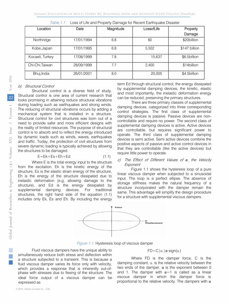
Table.1.1 :
Loss of Life and Property Damage for Recent Earthquake Disaster
Location
Date
Magnitude
LossofLife
Property Damage
Northridge 17/01/1994 6.8
60
$20billion
Kobe,Japan 17/01/1995 6.8
5,502
$147 billion
Kocaeli, Turkey 17/08/1999 7.8
15,637 $6.5billion
Chi-Chi,Taiwan 28/09/1999 7.7
2,400
$14billion
Bhuj,India 26/01/2001 8.0
20,005 $4.5billion
b)
Structural Control Structural control is a diverse field of study.
Structural control is one area of current research that looks promising in attaining reduce structural vibrations during loading such as earthquakes and strong winds. The reducing of structural vibrations occurs by adding a mechanical system that is installed in a structure. Structural control for civil structures was born out of a need to provide safer and more efficient designs with the reality of limited resources. The purpose of structural control is to absorb and to reflect the energy introduced by dynamic loads such as winds, waves, earthquakes and traffic. Today, the protection of civil structures from severe dynamic loading is typically achieved by allowing the structures to be damaged.
E=Ek+Es+Eh+Ed (1.1) Where E is the total energy input to the structure
from the excitation, Ek is the kinetic energy of the structure, Es is the elastic strain energy of the structure, Eh is the energy of the structure dissipated due to inelastic deformation (e.g, allowing damage to the structure), and Ed is the energy dissipated by supplemental damping devices. For traditional structures, the right hand side of the equation (1.1) includes only Ek, Es and Eh. By including the energy
term Ed through structural control, the energy dissipated by supplemental damping devices, the kinetic, elastic and most importantly, the inelastic deformation energy can be reduced, preserving the primary
structures.
There are three primary classes of supplemental damping devices, categorized into three corresponding control strategies. The first class of supplemental damping devices is passive. Passive devices are non-controllable and require no power. The second class of supplemental damping devices is active. Active devices are
controllable,
but requires significant power to
operate. The third class of supplemental damping devices is semi active. Semi active devices combine the positive aspects of passive and active control devices in that they
are controllable (like the active devices) but
require little power to operate.
c)
The Effect of Different Values of α, the Velocity Exponent
Figure 1.1 shows the hysteresis loop of a pure linear viscous damper when subjected to a sinusoidal input. The loop is a perfect ellipse. The absence of storage stiffness makes the natural frequency of a structure incorporated with the damper remain the same. This advantage will simplify the design procedure for a structure with supplemental viscous dampers.
Figure 1.1: Hysteresis loop of viscous damper
Fluid viscous dampers have the unique ability to simultaneously reduce both stress and deflection within a structure subjected to a transient. This is because a fluid viscous damper varies its force only with velocity, which provides a response that is inherently out-of-phase with stresses due to flexing of the structure. The ideal force output of a viscous damper can be expressed as
FD=C|u.|α
sign(u.)
Where FD is the damper force, C is the damping constant, u. is the relative velocity between the two ends of the damper, α
is the exponent between 0 and 1. The damper with α=1 is called as a linear
Globa
l Jo
urna
l of
Resea
rche
s in E
nginee
ring
()
Volum
e X
VI Issue
I V
ersion
I
22
Year
2016
FESeismic Evaluation of Multi Storey RC Buildings with and without Fluid Viscous Dampers
viscous damper in which the damper force is proportional to the relative velocity. The dampers with α
© 2016 Global Journals Inc. (US)

larger than 1 have not been seen in the practical applications. The damper with α
smaller than 1 is called as a non-linear viscous damper
which is effective in minimizing high velocity shocks. The below figure 1.2 shows the force velocity relationships of the three different
types of viscous dampers. This figure
demonstrates the efficiency of non
-
linear dampers in minimizing high velocity shocks. For a small relative velocity, the damper with a α
value less than 1 can give
a larger damping force than the other two types of dampers.
Figure 1.2 : Force- Velocity Relationship Viscous Damper
Line 1: FD=CN1 Vα , Non-linear damper with α >1. Line 2: FD=CL Vα , Linear Damper. Line 3: FD=CN2 Vα , Non-linear damper with α<1.
d) Placement of FVDs in a structure Having determined the target building
performance and required damping contribution to the response, the designer must identify appropriate locations to install the dampers. Often this is in the form of diagonal braces in which the damper device is placed in-line with the brace member. However as demonstrated by Constantinou et al. [1] and Şigaher and Constantinou [2], there are a many configurations that could be considered which can avoid significant architectural and functional compromise. The key point is that the damper must connect to points in the
structure that have differential motion when the building sways. This motion can be either horizontal or vertical depending on the primary lateral force resisting system and the inherent deformed shape of the structure. The use of ‘toggle-brace’ configurations can significantly increase the velocity applied to the damper using geometric amplification as shown in figure 1.3, and this corresponds to improved efficiency of the damper in terms of lateral force resistance and energy dissipation. Such setups can be used to reduce the size of the damper, or improve the damping effect on the structure. It should be noted however that experimental studies on toggle setups have generally not achieved the calculated efficiencies due to the brace and connection flexibility reducing the velocity amplification.
Figure 1.3 : Configurations for viscous dampers within a basic structural frame.
Figure adapted from Şigaher and Constantinou (2003)
e) Installation of FVD’s Fluid viscous dampers can be installed as
diagonal members in several ways, or can tie
intochevron braces. They can also be used as the two elements of the chevron braces. As show in figures 1.4 the typical fluid viscous dampers installations.
Globa
l Jo
urna
l of
Resea
rche
s in E
nginee
ring
()
Volum
e X
VI Issue
I V
ersion
I
23
Year
2016
FE
Seismic Evaluation of Multi Storey RC Buildings with and without Fluid Viscous Dampers
© 2016 Global Journals Inc. (US)

Fluid Viscous Dampers Can Be Installed In Several Ways As Shown In Following Figures
Figure 1.4 : Diagonal Bracing with Dampers
II. Review of Literature
Jinkoo K. and B. Sunghyuk [3] they investigated on appropriate plan-wise distribution of viscoelastic dampers to minimize the torsional responses of an asymmetric structure, with one axis of symmetry subjected to an earthquake-induced dynamic motion. The modal characteristic equations of a single-storey asymmetric structure with four corner columns and added viscoelastic dampers were derived, and a parametric study was performed to identify the design variables that influence the torsional responses. Based on the results of parametric study, a simple and straightforward methodology to find out the optimum eccentricity of added VED to compensate for the torsional effect of a plan-wise asymmetric structure was developed using modal coefficients. The results indicate that the torsional response of asymmetric structures can be reduced significantly following the proposed method, and that the viscoelastic dampers turn out to be more
effective than viscous dampers in controlling torsional response of a plan-wise asymmetric building structure.
Diclelia, M. and A. Mehta[4] they studied of seismic performance of steel chevron braced frames (CBFs) with and without viscous fluid dampers (VFDs) as a function of the intensity and frequency characteristics of the ground motion and VFD parameters. For this purpose, comparative nonlinear time history (NLTH) analyses of single and multiple story CBFs with and without VFDs are conducted using ground motions with various frequency characteristics scaled to represent small, moderate and large intensity earthquakes. Additionally, NLTH analyses of single and multiple story CBFs with VFDs are conducted to study the effect of the damping ratio and velocity exponent of the VFD on the seismic performance of the frames. The analysis results revealed that the seismic performance of the CBFs without VFDs is very poor and sensitive to the frequency characteristics and intensity of the ground motion due to brace buckling effects. Installing VFDs
Globa
l Jo
urna
l of
Resea
rche
s in E
nginee
ring
()
Volum
e X
VI Issue
I V
ersion
I
24
Year
2016
FESeismic Evaluation of Multi Storey RC Buildings with and without Fluid Viscous Dampers
© 2016 Global Journals Inc. (US)

into the CBFs significantly improved their seismic performance by maintaining their elastic behavior. Furthermore, VFDs with smaller velocity exponents and larger damping ratio are observed to be more effective in improving the seismic performance of the CBFs. However, VFDs with damping ratios larger than 50% do not produce significant additional improvement in the seismic performance of the CBFs.
Lap-Loi et al [5] they investigated on Optimal design theory for linear tuned mass dampers (TMD) has been thoroughly investigated, but is still under development for nonlinear TMDs. In this paper, optimization procedures in the time domain are proposed for design of a TMD with nonlinear viscous damping. A dynamic analysis of a structure implemented with a nonlinear TMD is conducted first. Optimum design parameters for the nonlinear TMD are searched using an optimization method to minimize the performance index. The feasibility of the proposed optimization method is illustrated numerically by using the Taipei 101 structure implemented with TMD. The sensitivity analysis shows that the performance index is less sensitive to the damping coefficient than to the frequency ratio. Time history analysis is conducted using the Taipei 101 structure implemented with different TMDs under wind excitation. For both linear and nonlinear TMDs, the comfort requirements for building occupants are satisfied as long as the TMD is properly designed. It was found that as the damping exponent increases, the relative displacement of the TMD decreases but the damping force increases.
Providakis, C.P [6] has studied isolation is a quite sensible structural control strategic design in reducing the response of a structural system induced by strong ground motions. It is clear that the effects of near-fault (NF) ground motions with large velocity pulses can bring the seismic isolation devices to critical working conditions. In the present paper, nonlinear time history analyses were performed using a commercial structural analysis software package to study the influence of isolation damping on base and superstructure drift. Various lead-rubber bearing (LRB) isolation systems are systematically compared and discussed for aseismic performances of two actual reinforced concrete (RC) buildings. Parametric analysis of the buildings fitted with isolation devices is carried out to choose the appropriate design parameters.
Dong-dong et al [7] studied the dynamic response analysis of damper connected adjacent multi storey structures with uncertain parameters. They considered uncertainities of mass and stiffness firstly. The ground acceleration is represented by Kanai- Tajimi filtered non-stationary process. The mean square random responses of structural displacement and storey drift are chosen as the optimization objectives. The variations of mean square responses of top floor displacements and bottom storey drifts in neighboring
structures with the damper stiffness and damping coefficient are analyzed in detail. Through the parametric study, the acquiring optimum parameters of damper are regarded as numerical results. A comparative study proves that the optimal theoretical values of damper parameters are very close to those through extensive numerical parametric studies. The theory results are calculated using the first natural frequencies and the total mass of the adjacent deterministic structures with mean parameters. To mitigate the mean square random responses of displacement, acceleration and inter storey drift in adjacent structures, the performance of connecting dampers is investigated. The numerical results demonstrate that coupling adjacent structures is an effective means of protection for flexible building structures.
Huangshang and Linuo [7] carried out work to obtain the optimal parameters of dampers linking adjacent structures for seismic mitigation, two SDOF systems connected with visco-elastic damper (VED) are taken as research object and the primary structural vibration frequency ratio, connection stiffness and linking damping ratio as research parameters. Modified Kanai-Tajimi spectrum is selected to model the earthquake excitation. Finally, the seismic responses of example structures with or without connecting dampers are contrastively analyzed. The dependence of response mitigation effective on research parameters is highlighted. The results indicate fine earthquake reduction effectiveness of dampers connecting structures. It is also showed that optimal parameters of damper cannot reduce the seismic responses of the primary structures connected to the best extent simultaneously. Based on the studies they concluded that the seismic responses of both buildings could be considerably reduced if damper parameters are selected appropriately and the seismic mitigation effects are affected by the dynamic characteristics of adjacent structures are different enough. Finally the seismic reduction effect of the softer building can be more enhanced than that of the stiffer building by installing VFD’s.
Sadeghi Balkanlou et al [8] investigated dampers position and optimizing their position at the height of the structure are studied. It investigates about viscous damper systems and their effects on seismic behavior of multistory structures and determines effects of damper system position on structure height using uniform distribution and SSSA methods. In this research, three 4, 8, 12storey steel structure frames were selected as the understudy models. The models were designed and analyzed based on available Codes to represent a sample of available structures. To evaluate effects of specific features of damper system, two 15% and 25% target values were considered for effective damping ratio of the damper system such that the results serve
Globa
l Jo
urna
l of
Resea
rche
s in E
nginee
ring
()
Volum
e X
VI Issue
I V
ersion
I
25
Year
2016
FE
Seismic Evaluation of Multi Storey RC Buildings with and without Fluid Viscous Dampers
© 2016 Global Journals Inc. (US)

as representative of appropriate spectrum of conventional features of damper system. Following time history analyses on the models created under three earthquake records which were caled according to spectrum design of Iran 2800 Code-3rd Ed.
Raveesh R M and Sahana T S [9] investigated evaluate effect of tuned mass dampers on the structural response of multistorey RC frame structures subjected to implemental dynamic analysis. A multistorey RC frame structure buildings having a ratio of height to breadth from 1, 2 and 3 is used in this study. The models were used to represent buildings located in zone 5 of India. The systemic parameters studied are natural time period, base shear, roof displacement, lateral displacement. A single ground motions were used in the study to generate single record Time v/s Acceleration curves namely BHUJ EARTHQUAKE. These ground motions was scaled to the design spectral acceleration prior to the application. The effect of acceleration is examined in this analysis SAP 2000, a program capable of performing nonlinear dynamic analysis. Based on the analysis results, it has been
concluded that the effect of tuned mass dampers plays a significant role to decrease the natural frequency, base shear, roof displacement, lateral displacement, story drift, bending moment and shear force in a multistorey RC framed Structure.
III. Modelling and Seismic Analysis
The majority of buildings in which floor
diaphragms are sufficiently rigid in their planes, the dynamic analysis can be carried out by using reduced 3D model. This is based on the following assumptions: i. The floors are rigid in their planes having 3 DOF’s,
to horizontal translations and a single rotation about a vertical axis.
ii. The mass of building and mass moment of inertia are lumped at the floor levels at the corresponding degrees of freedom.
iii. The inertia forces or movements due to vertical or rotational components of joint motions are negligible, therefore ignored.
Fig. 3.1 : Building Model with 3DOFs
The simplified model with above assumptions is shown in Fig. 3.1. The dynamic degrees of freedom are drastically reduced by static condensation and yet it produces quite accurate results. In case, the floor diaphragms are not adequately rigid in buildings with very stiff vertically resisting elements such as elevator cores, and diaphragms having large openings, irregular shapes etc., the in-plane rigid assumption is not valid. In such cases, a more complex model with additional degrees of freedom is considered to properly represent in-plane flexibility. The floor slabs in such cases can be idealized as an assemblage of finite elements.
b) Analysis Using Sap 2000 The entire analysis has done for all the 3D
models using SAP 2000 nonlinear version software. The results will be tabulated in order to focus the parameters such as time period, base shear, story drift and lateral displacements in linear analysis.
c) Response Spectrum Method Dynamic analysis of the building models is
performed using SAP 2000. The lateral loads generated
by ETABS correspond to the seismic zone V and 5% damped response spectrum given in IS 1893 (Part 1): 2002. The fundamental natural period values are calculated by SAP 2000, by solving the Eigen value problem of the model. Thus, the total earthquake load generated and its distribution along the height corresponds to the mass and stiffness distribution as modeled by SAP 2000. Here, as in the equivalent static analysis, the seismic mass is calculated using full dead load plus 25% of live load. The 5% damped response spectrum is considered for all modes of the building. For the modal combination the square root of sum of squares (SRSS) method is considered, because in this method of modal combination coupling of the modes doesn’t take place. For each displacement and force in the structure, the modal combinations produce a single positive results for each direction of acceleration, these directional value for a given response quantity have to be combined to produce a single positive result, and for this directional combination, CQC method is adopted. After defining the response spectrum case, analysis is carried out.
Globa
l Jo
urna
l of
Resea
rche
s in E
nginee
ring
()
Volum
e X
VI Issue
I V
ersion
I
26
Year
2016
FESeismic Evaluation of Multi Storey RC Buildings with and without Fluid Viscous Dampers
© 2016 Global Journals Inc. (US)
a) Modelling of the Multistorey Building

d) Pushover Analysis After the linear static analysis the designing of
3D Building model for gravity load combinations as per IS 456-2000 has done. Later assign the default hinge properties available in SAP 2000 Nonlinear as per ATC-40 to the frame elements. For the beam default hinge that yields based upon the flexure (M3) is assigned, for the column default hinge that yields based upon the interaction of the axial force and bending moment (P M2 M3) is assigned.
Define three static pushover cases. In the first case gravity load is applied to the structure, in the second case lateral load is applied to the structure along X-direction and in the third case lateral load is applied to the structure along Y-direction.
The buildings are pushed to a displacement of 4% of height of the building to reach collapse point as per ATC 40 (Applied Technology Council). Tabulate the nonlinear results in order to obtain the inelastic behavior.
The effective stiffness of friction damper is (0.2 to 1.2 times the initial stiffness (ki) of the frame structures) and damping coefficient. Initial elastic stiffness of modelled frame structures is determined from non-linear static analysis (Pushover curve) and damping
ratio is a function of structure mass, stiffness and damping ratio. In the present study damping ratio is taken as 5% of the critical value and mass of the frame structure is computed by using total gravity dead loads.
Where, Damping Coefficient=ξ x 2√ ξ = Damping ratio Ki = Initial stiffness.
In the present study reinforced concrete
moment resisting frame building of G+20 are considered. The plan layout, elevations and 3D view of all storeyed buildings with and without dampers are as shown in the below Figures. The building is considered to be located in the seismic zone v and intended for commercial purpose. Model-I Building without dampers. Model-II –Building with dampers.
Fig. 3.2 : Plan of Selected Multistorey Building Model
Fig. 3.3 : Model G+20 without FVD
Globa
l Jo
urna
l of
Resea
rche
s in E
nginee
ring
()
Volum
e X
VI Issue
I V
ersion
I
27
Year
2016
FE
Seismic Evaluation of Multi Storey RC Buildings with and without Fluid Viscous Dampers
© 2016 Global Journals Inc. (US)
e) Details of Selected Building
The building of G+20 has been modeled by providing with and without damper providing all parameters using SAP 2000 software. The building considered to model as shown in following figures.

Fig. 3.4 : Model G+20 with FVD
The analysis has been carried out by Equivalent Static Method and Response Spectrum Method.The results of Time period, Lateral displacement, Base shear, Storey drift were determined for all models.
f) Load Combinations The following load combinations are considered
for the analysis and design as per IS: 1893-2002.
Table 3.1: Load combinations as per IS: 1893-2002 and IS: 875 (Part3)-1987
LoadCombination
LoadFactors
Gravityanalysis
1.5(DL+LL)
Equivalentstaticanalysis
1.2(DL+LL±EQX)
1.2(DL+LL±EQY)
1.5(DL±EQX)
1.5(DL±EQY)
0.9(DL±EQX)
0.9(DL±EQY)
Responsespectrum analysis
1.2(DL+LL±RSX)
1.2(DL+LL±RSY)
1.5(DL±RSX)
1.5(DL±RSY)
0.9(DL±RSX)
0.9(DL±RSY)
The example of buildings considered in the present study is appropriately modeled in SAP 2000 by giving all the required input data mentioned in the APPENDIX A. The building models are analyzed separately as per the analysis methods mentioned in Table 3.1 with respect to the load combinations
IV.
Results and Discussions
a)
Natural Time Periods
The natural time periods obtained from seismic code IS 1893 (Part 1) -2000 and analytical results obtained using (SAP 2000) are given in Table 4.1 and Fig.4.1.
Globa
l Jo
urna
l of
Resea
rche
s in E
nginee
ring
()
Volum
e X
VI Issue
I V
ersion
I
28
Year
2016
FESeismic Evaluation of Multi Storey RC Buildings with and without Fluid Viscous Dampers
© 2016 Global Journals Inc. (US)

Table
4.1 : Codal and Analytical Time Period (seconds) for all storey building as per
IS 1893 (Part l) – 2000
BUILDING
MODELS GRAVITYANALYSIS
CODAL 1.5(DL+IL)
G+20
ModelI
1.8150
3.5177
ModelII 1.8150
1.9832
Fig.4.1 : Natural time period (seconds) profile for all Storey buildings for codal and analytical load combination as per IS1893 (Part 1) -2000.
(i)
Model-I: Building without damper. (ii)
Model-II: Building with damper.
The fundamental natural periods obtained for the seismic designed building and gravity models have plotted in Fig. 4.1 From the
plot it is very clear that,
stiffness of the building is directly proportional to its natural frequency and hence inversely proportional to the natural period. That is, if the stiffness of building is increased the natural period goes on decreasing. And as the natural frequency of the taller buildings is high due to the more mass, the natural period goes on increasing for three different multi storied buildings. The comparison of natural period presented in the table or plot shows that, the code IS 1893 (Part-I) 2002 uses empirical formula to calculate natural period which is directly depends on the height of the building. Whereas the analytical procedure calculates the natural period on the basis of mass and stiffness of the building (Eigen value and Eigen vectors).
b)
Base Shear
In the response spectrum method the design base shear (VB) is made equal to the base shear obtained from equivalent static method V B as per clause 7.8.2 of IS: 1893(Part 1):2002 by applying the scaling factors calculated as shown in Table 4.2 to 4.4.
Globa
l Jo
urna
l of
Resea
rche
s in E
nginee
ring
()
Volum
e X
VI Issue
I V
ersion
I
29
Year
2016
FE
Seismic Evaluation of Multi Storey RC Buildings with and without Fluid Viscous Dampers
The base shear is a function of mass, stiffness, height, and the natural period of the building structure.
From the previous results it is very clear that the fundamental natural periods obtained from the code, fall far short from that of the analytical natural periods. And in the equivalent static method design horizontal acceleration value obtained by codal natural period is adopted, and the basic assumption in the equivalent static method is that only first mode of vibration of building governs the dynamics and the effect of higher modes are not significant therefore, higher modes are not considered in this method. Hence base shears obtained from the equivalent static method are larger than the dynamic response spectrum method where in the dynamic response spectrum, all the modes of the building are considered, and first mode governs in the shorter buildings and as the storey increases for tall buildings, the flexibility increases and higher modes come into picture. The base shear for the equivalent static method (VB) and the response spectrum method (V B ) as per IS 1893 (Part 1): 2002 for the various building models are listed in the tables below.
© 2016 Global Journals Inc. (US)

Table 4.2 : Base shear and scaling factors for all models for 1.2(DL+LL+EQL) Combination
Storey
Base shear in kN for Model-I Baseshear in kN
for Model–II
EQX
RSX
Scale
Factor
EQY
RSY
Scale
Factor
EQX
RSX
Scale
Factor
EQY
RSY
Scale
Factor
G+20 7957.35 4408.74 1.8049 7995.65 4284.22 1.8663 8804.51 6073.75 1.4496 8827.41 5955.21 1.4823
Table 4.3 :
Base shear and scaling factors for all models for 1.5(DL+EQL) combination
Storey
Base shear inkN for Model-I Base shear in kN forModel-II
EQX
RSX
Scale
Factor
EQY
RSY
Scale
Factor
EQX
RSX
Scale
Factor
EQY
RSY
Scale
Factor
G+20 9946.69 5268.54 1.8879 9946.69 5201.59 1.9122 11005.69 755.89 1.4558 11005.69 6974.89 1.5779
Table 4.4 : Base shear and scaling factors for all models for 0.9(DL+EQL) combination
Storey
Base shear in kN for Model-I Base shear in kN for Model–II
EQX
RSX
Scale
Factor
EQY
RSY
Scale
Factor
EQX
RSX
Scale
Factor
EQY
RSY
Scale
Factor
G+20 9946.69 5268.54 1.8879 9946.69 5201.59 1.9122 11005.69 7559.89 1.4558 11005.69 6974.89 1.5779
(i) Model – I: Building without Damper. (ii) Model – II: Building with Damper.
The base shear is a function of mass, stiffness, height, and the natural period of the building structure. Moreover the basic assumption in the equivalent static method is that only first mode of vibration of building governs the dynamics of the structures. In dynamic response spectrum method, all the modes of the building are considered, and the first mode governs in the case of shorter buildings and as the number of storeys increase for tall buildings, the flexibility increases and higher modes come into picture. Hence base shears obtained from the equivalent static method are larger than the base shear obtained from dynamic response spectrum method. The base shear values obtained by equivalent static method are higher than those obtained by Response spectrum method for gravity and seismic analysis for G+20 buildings. c) Lateral Displacement
The lateral displacements obtained for equivalent static method (EQS) and response spectrum method (RSP) for 11 to 21 storey building models, along both X and Y directions are listed in the tables below. In order to account the effect of torsion the displacements are captured in both directions when force is acting in particular direction. Table 4.5 shows the lateral displacements of G+20 storied building with and
without damper, by taking load combinations in consideration. Similarly fig.4.2 to 4.7 indicates the plot of lateral displacements versus storey number for various load combinations.
Globa
l Jo
urna
l of
Resea
rche
s in E
nginee
ring
()
Volum
e X
VI Issue
I V
ersion
I
30
Year
2016
FESeismic Evaluation of Multi Storey RC Buildings with and without Fluid Viscous Dampers
© 2016 Global Journals Inc. (US)

Table 4.5 : Lateral displacement of G+20 storey building models for seismic analysis
(a)Longitudinal direction for seismic combination1.2(DL+LL+EQX)and1.2(DL+LL+RSX)
STOREY
Equivalent static method Respon sespectrum method
Lateral displace ment(mm) Lateral displacement(mm) ModelI ModelII ModelI ModelII
21 345.68 149.53 239.11 91.04 20 340.87 146.98 236.24 89.67 19 333.40 143.29 231.81 87.69 18 323.26 138.48 225.87 85.14 17 310.64 132.64 218.54 82.07 16 295.73 125.87 209.86 78.52 15 280.29 118.97 200.79 74.90 14 263.41 111.51 190.76 70.94 13 245.20 103.51 179.75 66.64 12 225.81
95.06 167.78 62.02
11 205.41 86.23
154.84 57.08 10 185.20
77.60 141.69 52.14
9 164.44 68.80
127.84 46.99 8 143.24
59.86 113.28 41.61
7 121.71 50.82
98.01
35.99 6 100.05 41.77
82.03 30.15
5 79.04 33.08 65.92 24.31 4 58.38 24.55 49.51 18.37 3 38.56 16.34 33.21 12.42 2 20.57 8.81 17.94 6.79
1 6.37 2.76 5.61 2.15
BASE 0.00 0.00 0.00 0.00
(b)Transverse
direction for seismic combination1.2(DL+LL+EQY)and1.2(DL+LL+RSY)
STOREY
Equivalen tstatic method Responsespectrummethod
Lateral displacement(mm)
Lateraldisplacement(mm)
ModelI ModelII ModelI ModelII
2
396.39
166.85
221.18
97.85
2
389.73
163.47
217.82
96.02
1
380.34
158.96
213.21
93.63
1
368.04
153.28
207.26
90.67
1
353.04
146.51
200.10
87.19
1
335.58
138.77
191.78
83.23
Globa
l Jo
urna
l of
Resea
rche
s in E
nginee
ring
()
Volum
e X
VI Issue
I V
ersion
I
31
Year
2016
FE
Seismic Evaluation of Multi Storey RC Buildings with and without Fluid Viscous Dampers
© 2016 Global Journals Inc. (US)

1
317.41 130.87 183.05 79.18
1
297.73 122.39 173.53 74.81
1
276.62 113.37 163.17 70.12
1
254.27 103.89 151.99 65.11
1
230.87 94.03 140.00 59.79
1
207.64 84.41 127.79 54.48
9 183.90 74.62 115.02 48.97
8 159.73 64.72 101.66 43.24
7 135.30 54.78 87.72 37.30
6 110.85 44.85 73.21 31.14
5 87.19 35.37 58.60 25.01
4 64.06 26.11 43.81 18.80
3 42.04 17.27 29.22 12.65
2 22.24 9.25 15.67 6.87
1 6.8
2.89 4.85 2.17
BASE 0.0
0.00 0.00 0.00
(c)Longitudinal direction for seismic combination1.5(DL+EQX)and1.5(DL+RSX)
STOREY Equivalent static method Response spectrum method
Lateral displace ment (mm) Lateral displace ment(mm)
ModelI ModelII ModelI ModelII
21 432.06 186.06 298.85 112.96
20 426.03 182.87 295.24 111.23
19 416.69 178.25 289.70 108.74
18 404.02 172.24 282.29 105.56
17 388.26 164.96 273.13 101.75
16 369.63 156.52 262.29 97.33
15 350.32 147.91 250.95 92.82
14 329.23 138.62 238.41 87.91
13 306.47 128.66 224.66 82.58
12 282.24 118.14 209.70 76.84
11 256.74 107.16 193.54 70.72
10 231.48 96.42 177.10 64.60
9 205.54 85.47 159.79 58.21
8 179.03 74.35 141.59 51.54
7 152.13 63.12 122.51 44.58
6 125.05 51.88 102.54 37.35
5 98.79 41.07 82.40 30.11
Globa
l Jo
urna
l of
Resea
rche
s in E
nginee
ring
()
Volum
e X
VI Issue
I V
ersion
I
32
Year
2016
FESeismic Evaluation of Multi Storey RC Buildings with and without Fluid Viscous Dampers
. . . .
4 72.97 30.48 61.89 22.75
© 2016 Global Journals Inc. (US)

3 48.20 20.28 41.51 15.39
2 25.71 10.94 22.42 8.41
1 7.96 3.42 7.01 2.66
BASE 0.00 0.00 0.00 0.00
(d)Transverse direction for seismi ccombination1.5(DL+EQY)and1.5(DL+RSY)
STOREY
Equivalent static method Response spectrum method
Lateral displacement(mm) Lateral displacement(mm)
ModelI ModelII ModelI ModelII
21 495.35 207.57 276.34 121.31
20 487.05 203.36 272.16 119.04
19 475.32 197.72 266.41 116.05
18 459.95 190.63 258.98 112.36
17 441.21 182.19 250.04 108.03
16 419.39 172.53 239.64 103.11
15 396.70 162.69 228.75 98.08
14 372.10 152.13 216.85 92.66
13 345.73 140.90 203.91 86.84
12 317.80 129.11 189.95 80.63
11 288.55 116.83 174.97 74.03
10 259.53 104.87 159.71 67.46
9 229.85 92.70 143.75 60.63
8 199.64 80.39 127.06 53.54
7 169.11 68.03 109.63 46.18
6 138.55 55.70 91.50 38.55
5 108.98 43.92 73.25 30.97
4 80.07 32.42 54.76 23.28
3 52.54 21.44 36.52 15.66
2 27.80 11.49 19.59 8.51
1 8.51 3.60 6.06 2.69
BASE
0.00 0.00 0.00 0.00
Globa
l Jo
urna
l of
Resea
rche
s in E
nginee
ring
()
Volum
e X
VI Issue
I V
ersion
I
33
Year
2016
FE
Seismic Evaluation of Multi Storey RC Buildings with and without Fluid Viscous Dampers
© 2016 Global Journals Inc. (US)

Globa
l Jo
urna
l of
Resea
rche
s in E
nginee
ring
()
Volum
e X
VI Issue
I V
ersion
I
34
Year
2016
FESeismic Evaluation of Multi Storey RC Buildings with and without Fluid Viscous Dampers
© 2016 Global Journals Inc. (US)
(e)Longitudinal direction forseismic combination0.9(DL+EQX)and0.9(DL+RSX)
STOREY
Equivalent static method Responsespectrummethod
Lateral displace ment(mm) Lateral displace ment(mm)
ModelI ModelII ModelI ModelII
21 432.08 185.58 298.87 112.48
20 426.02 182.38 295.24 110.7519 416.69 177.77 289.70 108.27
18 404.02 171.77 282.29 105.10
17 388.25 164.51 273.13 101.2916 369.63 156.08 262.29 96.90
15 350.32 147.49 250.95 92.4114 329.23 138.22 238.41 87.5113 306.47 128.29 224.66 82.20
12 282.24 117.79 209.70 76.49
11 256.74 106.84 193.54 70.40
10 231.48 96.12 177.09 64.30
9 205.54 85.20 159.79 57.94
8 179.03 74.11 141.59 51.30
7 152.13 62.91 122.50 44.38
6 125.05 51.70 102.54 37.17
5 98.79 40.93 82. 29.97
4 72.97 30.37 61. 22.64
3 48.20 20.21 41. 15.32
2 25.71 10.90 22. 8.37
1 7.96 3.41 7. 2.65
BASE 0.00 0.00 0.00 0.00
(f)transverse direction for seismic combination0.9(DL+EQY)and0.9(DL+RSY)
STOREY
Equivalentstaticmethod Response spectrum method
Lateral displace ment(mm) Lateral displace ment(mm)
ModelI ModelII ModelI ModelII
21 495.33 207.03 276.33 120.78
20 487.05 202.83 272.16 118.51
19 475.31 197.20 266.41 115.53
18 459.95 190.12 258.98 111.85
17 441.21 181.70 250.04 107.54
16 419.39 172.05 239.64 102.63
15 396.70 162.24 228.75 97.63

Fig. 4.2 :
Lateral displacement (mm) profile for G+20 storey in Longitudinal direction By Seismic 1.2 EQX and RSX
14
372.11
151.70
216.85
92.23
13
345.73
140.49
203.91
86.43
12
317.80
128.72
189.95
80.25
11
288.55
116.48
174.97
73.68
10 259.53
104.55
159.71
67.14
9
229.85
92.41
143.75
60.34
8
199.64
80.13
127.06
53.28
7
169.11
67.80
109.63
45.96
6
138.55
55.51
91.50
38.36
5 108.98
43.77
73.25
30.82
4 80.07
32.30
54.76
23.17
3
52.54
21.36
36.52
15.58
2 27.80
11.45
19.59
8.47
1
8.51
3.59
6.06
2.68
BASE
0.00
0.00
0.00
0.00
Globa
l Jo
urna
l of
Resea
rche
s in E
nginee
ring
()
Volum
e X
VI Issue
I V
ersion
I
35
Year
2016
FE
Seismic Evaluation of Multi Storey RC Buildings with and without Fluid Viscous Dampers
© 2016 Global Journals Inc. (US)
.

Fig.4.3
:
Lateral displacement (mm) profile for G+20 storey in Transverse direction
by
Seismic 1.2 EQX and RSY
Fig.
4.4
: Lateral displacement (m) profile for G+20 storey in longitudinal direction by
Seismic 1.5 EQX and RSX
Fig.4.5 :
Lateral displacement (mm) profile for G+20 storey in Transverse
direction by Seismic 1.5 EQY and RSY
Globa
l Jo
urna
l of
Resea
rche
s in E
nginee
ring
()
Volum
e X
VI Issue
I V
ersion
I
36
Year
2016
FESeismic Evaluation of Multi Storey RC Buildings with and without Fluid Viscous Dampers
© 2016 Global Journals Inc. (US)

Fig.4.6 :
Lateral displacement (mm) profile for G+20 storey in Longitudinal direction by
Seismic 0.9 EQX and RSX
Fig.4.7:
Lateral displacement (mm) profile for G+20 storey in Transverse direction by
Seismic 0.9 EQY and RSY
For all the load combination the lateral
displacement is maximum at roof level has a maximum value of 432.06mm for model I compared to model II maximum value of 186.06mm in longitudinal direction for equivalent static method. And in response spectrum method model I and model II have displaced maximum values of 298.85mm and 112.96mm respectively in longitudinal direction. Similarly, in transverse direction model I has displaced 495.35mm and model II 207.57mm for equivalent static method, in response spectrum method model I and model II have displaced 276.34mm and 121.31mm respectively.
This clearly shows that the fluid viscous damper are effective reducing the lateral displacement due to seismic loads.
From the results of roof
displacement for Model I (bare frame without FVD) and Model II (building with FVD) it can be observed that Model I gives maximum displacement for G+20 storey buildings analysed for seismic loads which gives maximum displacement for Model I. Lateral displacements increases as the number of stories increases. So the lateral displacement can be reduced by introduction of FVD in building.
Globa
l Jo
urna
l of
Resea
rche
s in E
nginee
ring
()
Volum
e X
VI Issue
I V
ersion
I
37
Year
2016
FE
Seismic Evaluation of Multi Storey RC Buildings with and without Fluid Viscous Dampers
© 2016 Global Journals Inc. (US)

d) Storey Drifts Inter Storey drifts for different models
obtained from the analysis are shown in Table.4.6 below. Inter Storey drifts profile can also be observed in Fig. 4.8 to 4.13.
According to IS 1893(Part 1):2002 clause 7.11.1 Storey drifts limitations are explained that the Storey
drifts in any storey due to the minimum specified design lateral force, with partial load factor of 1.0 shall not exceed 0.004 times the storey height. For 3.5 m storey height has got 14.00 mm.
Table 4.6 : Inter storey drift of G+20 storey building models for seismic analysis
(a)Longitudinal direction for seismic combination1.2(DL+LL+EQX)and1.2(DL+LL+RSX)
STOREY
Equivalent static method Responsespectrummethod
Inter Storey Drift(mm) Inter Storey Drift(mm)
ModelI ModelII ModelI ModelII
21 1.37 0.73 0.82 0.39
20 2.14 1.06 1.27 0.57
19 2.90 1.37 1.70 0.73
18 3.60 1.67 2.09 0.87
17 4.26 1.94 2.48 1.01
16 4.41 1.97 2.59 1.04
15 4.82 2.13 2.87 1.13
14 5.20 2.28 3.15 1.23
13 5.54 2.41 3.42 1.32
12 5.83 2.52 3.70 1.41
11 5.77 2.47 3.76 1.41
10 5.93 2.51 3.96 1.47
9 6.06 2.56 4.16 1.54
8 6.15 2.58 4.36 1.60
7 6.19 2.59 4.57 1.67
6 6.00 2.48 4.60 1.67
5 5.90 2.44 4.69 1.70
4 5.66 2.35 4.66 1.70
3 5.14 2.15 4.36 1.61
2 4.06 1.73 3.52 1.33
1 1.82 0.79 1.60 0.61
BASE 0.00 0.00 0.00 0.00
Globa
l Jo
urna
l of
Resea
rche
s in E
nginee
ring
()
Volum
e X
VI Issue
I V
ersion
I
38
Year
2016
FESeismic Evaluation of Multi Storey RC Buildings with and without Fluid Viscous Dampers
© 2016 Global Journals Inc. (US)

(b)Transverse direction for seismic combination1.2(DL+LL+EQY)and1.2(DL+LL+RSY)
STOREY
Equivalent static method Respon
sespectrum method
Inter Storey Drift(mm) Inter Storey Drift(mm)
ModelI ModelII ModelI ModelII
21 1.90
0.96
0.96
0.52
20 2.68
1.29
1.32
0.68
19 3.51
1.62
1.70
0.85
18 4.28
1.93
2.05
0.99
17 4.99
2.21
2.38
1.13
16 5.19
2.26
2.49
1.16
15 5.62
2.42
2.72
1.25
14 6.03
2.58
2.96
1.34
13 6.39
2.71
3.19
1.43
12 6.68
2.82
3.42
1.52
11 6.64
2.75
3.49
1.52
10 6.78
2.80
3.65
1.57
9 6.91
2.83
3.82
1.64
8 6.98
2.84
3.98
1.70
7 6.98
2.84
4.15
1.76
6 6.76
2.71
4.17
1.75
5 6.61
2.65
4.23
1.77
4 6.29
2.53
4.17
1.76
3 5.66
2.29
3.87
1.65
2 4.41
1.82
3.09
1.34
1 1.94
0.83
1.38
0.62
BASE
0.00
0.00
0.00
0.00
(c)Longitudinal direction for seismic combination1.5(DL+EQX)and1.5(DL+RSX)
STOREY
Equivalent static method Respon sespectrum method
Inter Storey Drift (mm) Inter Storey Drift (mm)
ModelI ModelII ModelI ModelII
21 1.72
0.91
1.03
0.49
20 2.67
1.32
1.58
0.71
19 3.62
1.72
2.12
0.91
18 4.50 2.08 2.62 1.09
17 5.32 2.41 3.10 1.26
Globa
l Jo
urna
l of
Resea
rche
s in E
nginee
ring
()
Volum
e X
VI Issue
I V
ersion
I
39
Year
2016
FE
Seismic Evaluation of Multi Storey RC Buildings with and without Fluid Viscous Dampers
© 2016 Global Journals Inc. (US)

16 5.52 2.46 3.24 1.29
15 6.03 2.66 3.58 1.40
14 6.50 2.84 3.93 1.52
13 6.92 3.01 4.27 1.64
12 7.29 3.14 4.62 1.75
11 7.22 3.07 4.70 1.75
10 7.41 3.13 4.94 1.82
9 7.57 3.18 5.20 1.91
8 7.69 3.21 5.45 1.99
7 7.74 3.21 5.71 2.07
6 7.50 3.09 5.75 2.07
5 7.38 3.03 5.86 2.10
4 7.08 2.91 5.82 2.10
3 6.43 2.67 5.45 1.99
2 5.07 2.15 4.40 1.64
1 2.27 0.98 2.00 0.76
BASE 0.00 0.00 0.00 0.00
(d)Transverse direction for seismic combination1.5(DL+EQY)and1.5(DL+RSY)
Equivalent static method Responsespectrummethod
Inter Storey Drift (mm) Inter Storey Drift (mm)
ModelI ModelII ModelI ModelII
21
2.37
1.20
1.19
0.65
20 3.35
1.61
1.64
0.85
19
4.39
2.03
2.12
1.06
18
5.35
2.41
2.56
1.24
17 6.23
2.76
2.97
1.41
16
6.48
2.81
3.11
1.44
15
7.03
3.02
3.40
1.55
14
7.54
3.21
3.70
1.66
13 7.98
3.37
3.99
1.77
12
8.35
3.51
4.28
1.88
11 8.29
3.42
4.36
1.88
10
8.48
3.48
4.56
1.95
9 8.63 3.52 4.77 2.03
8
8.72 3.53 4.98 2.10
7 8.73 3.52 5.18 2.18
6 8.45 3.36 5.21 2.17
Globa
l Jo
urna
l of
Resea
rche
s in E
nginee
ring
()
Volum
e X
VI Issue
I V
ersion
I
40
Year
2016
FESeismic Evaluation of Multi Storey RC Buildings with and without Fluid Viscous Dampers
© 2016 Global Journals Inc. (US)
STOREY

5 8.26 3.29 5.28 2.20
4 7.86 3.14 5.21 2.18
3 7.07 2.84 4.84 2.04
2 5.51 2.25 3.86 1.66
1 2.43 1.03 1.73 0.77
BASE 0.00 0.00 0.00 0.00
(e)Longitudinal direction for seismic combination0.9(DL+EQX)and0.9(DL+RSX)
STOREY
Equivalen tstatic method Responsespectrummethod
Inter Storey Drift (mm) Inter Storey Drift (mm)
ModelI ModelII ModelI ModelII
21 1.73 0.91 1.04 0.50
20 2.67 1.32 1.58 0.71
19 3.62 1.71 2.12 0.91
18 4.51 2.08 2.62 1.09
17 5.32 2.41 3.10 1.26
16 5.52 2.45 3.24 1.28
15 6.03 2.65 3.58 1.40
14 6.50 2.84 3.93 1.52
13 6.92 3.00 4.27 1.63
12 7.28 3.13 4.62 1.74
11 7.22 3.06 4.70 1.74
10 7.41 3.12 4.94 1.82
9 7.57 3.17 5.20 1.90
8 7.69 3.20 5.45 1.98
7 7.73 3.20 5.71 2.06
6 7.50 3.08 5.75 2.06
5 7.38 3.02 5.86 2.09
4 7.08 2.90 5.82 2.09
3 6.43 2.66 5.45 1.98
2 5.07 2.14 4.40 1.64
1 2.27 0.97 2.00 0.76
BASE 0.00 0.00 0.00 0.00
Globa
l Jo
urna
l of
Resea
rche
s in E
nginee
ring
()
Volum
e X
VI Issue
I V
ersion
I
41
Year
2016
FE
Seismic Evaluation of Multi Storey RC Buildings with and without Fluid Viscous Dampers
© 2016 Global Journals Inc. (US)
(f)transverse direction for seismic combination0.9(DL+EQY)and0.9(DL+RSY)
STOREY
Equivalent static method Response spectrum method
Inter Storey Drift(mm) Inter Storey Drift(mm)
ModelI ModelII ModelI ModelII
21 2.37 1.20 1.19 0.65
20 3.35 1.61 1.65 0.85
19 4.39 2.02 2.12 1.05
18 5.35 2.41 2.56 1.23
17 6.24 2.76 2.97 1.40
16 6.48 2.80 3.11 1.43
15 7.03 3.01 3.40 1.54
14 7.54 3.20 3.70 1.66
13 7.98 3.36 3.99 1.77
12 8.36 3.50 4.28 1.88
11 8.29 3.41 4.36 1.87
10 8.48 3.47 4.56 1.94
9 8.63 3.51 4.77 2.02
8 8.72 3.52 4.98 2.09
7 8.73 3.51 5.18 2.17
6 8.45 3.35 5.21 2.15
5 8.26 3.28 5.28 2.19
4 7.86 3.13 5.21 2.17
3 7.07 2.83 4.84 2.03
2 5.51 2.25 3.86 1.65
1 2.43 1.02 1.73 0.77
BASE 0.00 0.00 0.00 0.00
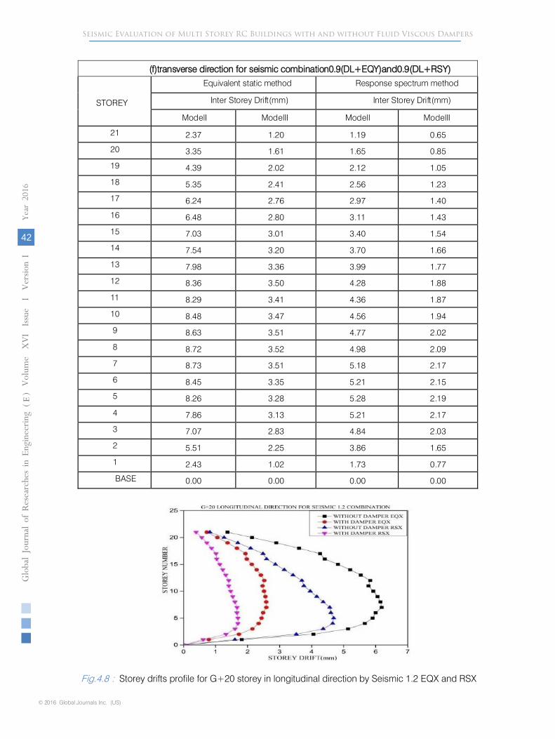
Fig.4.8 : Storey drifts profile for G+20 storey in longitudinal direction by Seismic 1.2 EQX and RSX
Globa
l Jo
urna
l of
Resea
rche
s in E
nginee
ring
()
Volum
e X
VI Issue
I V
ersion
I
42
Year
2016
FESeismic Evaluation of Multi Storey RC Buildings with and without Fluid Viscous Dampers
© 2016 Global Journals Inc. (US)

Fig. 4.9 : Storey drifts profile for G+20 storey in longitudinal direction by Seismic 1.5EQX and RSX
Fig. 4.10 : Storey drifts profile for G+20 storey in transverse direction by Seismic 1.2
EQY and RSY
Fig. 4.11 :
Storey drifts profile for G+20 storey in transverse direction by Seismic 1.5
EQY and RSY
Globa
l Jo
urna
l of
Resea
rche
s in E
nginee
ring
()
Volum
e X
VI Issue
I V
ersion
I
43
Year
2016
FE
Seismic Evaluation of Multi Storey RC Buildings with and without Fluid Viscous Dampers
© 2016 Global Journals Inc. (US)

Fig. 4.12 : Storey drifts profile for G+20 storey in longitudinal direction by Seismic 0.9 EQX and RSX
Fig. 4.13
: Storey drifts profile for G+20 storey in transverse direction by Seismic 0.9 and RSY
(i)
Model-I: Building without FVD
(ii)
Model-II: Building with FVD
For all the load combination the storey drift is maximum for model I compared to model II the model I has a maximum value of 7.74mm for model I compared to model II maximum value of 3.21mm in longitudinal direction for equivalent static method. And in response spectrum method model I and model II have drifted maximum values of 5.86mm and 2.10mm respectively in longitudinal direction. Similarly in transverse direction model I has drifted 8.73mm and model II 3.52mm for equivalent static method, in response spectrum method model I and model II have drifted 5.28mm and 2.20mm respectively.
This clearly shows that the fluid viscous dampers are effective reducing the storey drift due to seismic loads.
As per Clause 7.11.1 of IS 1893 (Part 1)2002 the inter storey drift in any storey should not exceed 0.004 times the storey height. From the results mentioned above it can be observed that Model I, Model II doesn’t crosses inter storey drift limits for equivalent static method and also Response spectrum method none of the buildings has crossed the drift limits in any direction for G+20 storey models.
From above results for Model I i.e. regular building has got more Storey drifts for G+20 and for Model II (building with fluid viscous dampers) has less storey drift compared to Model-I. The inter storey drift is more at the bottom storey than at the top storey and also as the number of storey increases the relative drift of the storey also increase. The introduction of fluid viscous dampers in the building drastically reduces the inter storey drift in the building.
Globa
l Jo
urna
l of
Resea
rche
s in E
nginee
ring
()
Volum
e X
VI Issue
I V
ersion
I
44
Year
2016
FESeismic Evaluation of Multi Storey RC Buildings with and without Fluid Viscous Dampers
© 2016 Global Journals Inc. (US)

Globa
l Jo
urna
l of
Resea
rche
s in E
nginee
ring
()
Volum
e X
VI Issue
I V
ersion
I
45
Year
2016
FE
Seismic Evaluation of Multi Storey RC Buildings with and without Fluid Viscous Dampers
V. Conclusions
The Present study is focused on the study of Seismic demands of different R.C buildings high rise buildings using various analytical techniques for the buildings located in seismic zone V of India medium soil. The Performance of the building is studied in terms of time period, base shear, lateral displacements, storey drifts in linear static and linear dynamic analysis for withand without fluid viscous dampers building G+20 storey models.
The seismic analysis is carried out by equivalent static method and response spectrum method for G+20 storey building with unsymmetrical in plan. The following are the conclusions which can be concluded from the present study, which are as follows.1. The fundamental natural period of the structure
increases due to lesser stiffness of the bare frame buildings compared to buildings having fluid viscous dampers.
2. The base shears due to seismic forces for the building with fluid viscous dampers are more than the base shear obtained for without fluid viscous dampers.
3. Compared to the regular building the storey displacement decreases for the buildings having fluid viscous dampers. Addition of fluid viscous dampers in the building will result in drastic reduction of lateral displacement of the building there by in turn assures the safety of the structure.
4. The storey drift increases in regular building as compared to building having fluid viscous dampers. T h e addition of fluid viscous dampers in the building drastically reduces the inter storey drift when compared to that of building without fluid viscous dampers.
References Références Referencias
1. Constantinou, M.C., Tsopelas, P., Hammel, W., and Sigaher, A.N. (2001). Toggle-brace-damper
seismic energy dissipation systems. Journal of Structural Engineering,127:2, 105–112.
2. Şigaher AN, Constantinou MC. “Scissor-Jack-Damper energy dissipation system”. Earthquake Spectra 2003; 19(1): 133-158.
3. Jinkoo K. and B. Sunghyuk, 2002 “Optimum distribution of added viscoelastic dampers for mitigation of torsional responses of plan-wise asymmetric structures” J. Eng. Struct., 24: 1257-1269.
4. Diclelia, M. and A. Mehta, 2007” Seismic performance of chevron braced steel frames with and without viscous fluid dampers as a function of ground motion and damper characteristics” J. Construct. Steel Res., 63: 1102-1115.
5. Lap-Loi, C., W. Lai-Yun, H. Hsu-Hui, C. Chung-Hsin and L. Kuan-Hua, 2009 “Optimal design theories of tuned mass dampers with nonlinear viscous damping” J. Earthquake Eng. Eng. Vibrat., 8: 41671-41674.
6. Providakis, C.P., 2008. Effect of LRB isolators and supplemental viscous dampers on seismic isolated buildings under near-fault excitations. J. Eng. Struct., 30: 1187-1198.
7. Huangsheng, S. and Linuo, C (2011). “Connecting Parameter Study on Adjacent Structures Linked by Dampers,” Advanced Materials Research, 243-249, 3832-3838.[8] V. Sadeghi Balkanlou , M. Reza Bagerzadeh Karimi , B. Bagheri Azar and Alaeddin Behravesh (2013) “Evaluating Effects of Viscous Dampers on optimizing Seismic Behavior of Structures”International Journal of Current Engineering and Technology ISSN 2277 -4106
8. Raveesh R M and Sahana T S (2014) “Effect of Tuned Mass Dampers on Multistorey RC Framed Structures” International Journal of Engineering Research & Technology (IJERT) ISSN: 2278-0181 Vol. 3 Issue 8, August - 2014
Appendixa
Design Data For All The Buildings
Structure SMRFNo.ofstorey G+20
Storeyheight 3.5m
Typeofbuildinguse CommercialSeismiczone V
MaterialPropertiesYoung’smodulus ofM20concrete,E 22.36x 10⁶kN/m2
© 2016 Global Journals Inc. (US)

Globa
l Jo
urna
l of
Resea
rche
s in E
nginee
ring
()
Volum
e X
VI Issue
I V
ersion
I
46
Year
2016
FESeismic Evaluation of Multi Storey RC Buildings with and without Fluid Viscous Dampers
Grade ofconcrete M35(beams,slabandcolumns)
Grade ofsteel Fe415Densityofreinforcedconcrete 25kN/m3
MemberPropertiesSlab 0.2m
Beam(forall models) 0.30x 0.60mG+20
Columnsize(Upto5thstorey) 0.9x0.9m
Columnsize(6thto 10th storey) 0.8x0.8m
Columnsize(11thto 15thstorey) 0.7x0.7m
Columnsize(16thto 21ststorey) 0.6x0.6m
AssumedDeadLoadIntensitiesRooffinishes(DPC) 1.5kN/m2
Floor finishes 1.0kN/m2
LiveLoadIntensitiesFloor 3.0kN/m2
LINK (FluidViscous Dampers) PROPERTIES1) EffectiveStiffness,KN/m
a) G+20 43664
2) DampingCo-efficient,KN-s/m
a) G+20 8843
IS:1893-2002EQUIVALENTSTATICMETHOD
Zo VZonefactor,Z(Table2) 0
Importancefactor,I(Table6) 1
Responsereductionfactor,R (Table7) 5Dampingratio 5%(forRCframedbuilding)
© 2016 Global Journals Inc. (US)