Embed Size (px)
Citation preview

Structural Analysis of Historical Constructions –Anamnesis, diagnosis, therapy, controls – Van Balen & Verstrynge (Eds)
© 2016 Taylor & Francis Group, London, ISBN 978-1-138-02951-4
Seismic design of tension wall-diaphragm anchorage for historicalunreinforced masonry buildings
S. MoreiraDepartment of Civil Engineering, Pontificia Universidad Católica del Perú-PUCP, Lima, Peru
L.F. Ramos, D.V. Oliveira & P.B. LourençoISISE, Department of Civil Engineering, University of Minho, Guimarães, Portugal
V.S. CóiasMonumenta Lda, Lisboa, Portugal
ABSTRACT: The absence of appropriate structural connections is known to be one of the main factors con-tributing to the activation of out-of-plane mechanisms of masonry walls that can compromise the entire stabilityof a building. The high vulnerability of historical unreinforced masonry buildings to these types of mechanismsimposes the necessity to develop engineered strengthening solutions capable of ensuring positive wall-diaphragmanchorage to work in tension. A design methodology was developed covering aspects related to the estimation ofthe seismic demand and the design of a retrofit solution studied experimentally. The procedure proposed relieson the assessment of the resistant capacity associated with several possible failure modes and the estimationof the seismic demand considering the existing recommendations found on Eurocode 8 (CEN/TC 250 2010),ASCE/SEI 41-13, and NZSEE (2006).
1 INTRODUCTION
Ensuring the presence of effective tension wall-diaphragm anchors is one of the primordial steps tobe addressed when retrofitting a building, in order toenable a continuous load path and a “box-like” behav-ior (Lourenço et al. 2011, CEN/TC250 2010, Senaldiet al. 2014).
In spite of their recognized importance, wall-diaphragm (or wall-to-floor) connections have notbeen subject of many experimental or numericalstudies. Only recently, pullout tests have been con-ducted on strengthened original or representative wall-diaphragm connections, in an effort to better character-ize retrofit solutions that have been applied historicallyor for several years already (metallic straps, ties,injection anchors, etc.).
Lin & LaFave (2012) carried out several pull-out tests on strengthened connections (representativespecimens with timber floor joists resting on slots openin the masonry wall), typical of pre-50s unreinforcedmasonry buildings (URM), to study their capacity andthe influence of different parameters on the results.While the unstrengthened connection relied only onfriction to resist to horizontal actions, the strength-ened connection was equipped with wall anchors madeof a steel strap and a threaded rod, welded together.The steel strap was nailed to the timber floor joist, bytwo nails, and the threaded rod was anchored on the
external face of the masonry wall portion, by meansof a washer and a standard hex nut. Its capacity wasestimated to be between 5.8 kN and 8.5 kN, and wasassociated with nails’ shear off and pullout. It was alsoconcluded that dynamic loading leads to more conser-vative displacements, in comparison with monotonicand quasi-static cyclic loadings, which consequentlyincreases brittleness of behavior.
Campbell et al. (2012) discussed failure modes ofwall-diaphragm connections strengthened with a simi-lar solution as the one studied by Lin & LaFave (2012),observed after the 2011 Christchurch earthquake. Themost common failure mode was punching shear failureof masonry, followed by yielding or rupture of the con-nector rod, rupture at weld between connector rod andjoist plate, and splitting of joist or stringer. The fail-ure modes concerning failure of fixing at joist plate,splitting or fracture of the anchor plate, and yieldingor rupture at threaded nut were not observed.
This paper focus on the results obtained from thequasi-static monotonic and cyclic tests performedon unstrengthened and strengthened wall-diaphragmspecimens by Moreira et al. (2014) and proposesa methodology for the design of the tested tensionwall-diaphragm anchors.
The type of wall-diaphragm connection studiedconsisted of a timber floor joist end nailed to a tim-ber wall-plate, embedded in the masonry wall. Thestrengthening solution developed is an evolution of the
1590

Figure 1. Example of strengthened wall-to-floor connec-tion: (a) Configuration of the strengthening solution; and (b)possible failure modes.
metal straps being applied for centuries. It consists of astainless steel angle bolted to the timber floor joist andanchored to the masonry wall, by means of a tie rodwith an anchor plate on the exterior face of the wall (seeFigure 1a). The experimental campaign enabled thecharacterization of failure modes, maximum pulloutforce, hysteretic behavior, energy dissipation, strengthand stiffness degradation as well as other parame-ters (Moreira 2015). The different types of damagesobserved, which by parameter variation can becomefailure modes in different scenarios are presented inFigure 1b, and further developed in Section 3.
Although one is addressing retrofit design at com-ponent level, the global perspective of the buildingshould always be taken into consideration. This meansthat the intervention should not decrease the over-all available ductility and if clear deficiencies aredetected, they should be corrected or improved asmuch as possible.
Previous studies pointed out that the strengthen-ing solution under study provides high ductility tothe wall-diaphragm connections, but causes a slightdecrease in comparison to the unstrengthened connec-tions. Although ductility is decreased at local level,strengthening the wall-diaphragm connections enablesthe formation of more ductile global failure modes thatexplore the in-plane capacity of walls (Moreira 2015).As part of the retrofit process, assessment of globalstructural performance before and after the proposedintervention, using linear or nonlinear procedures,should be considered.
The retrofit methodology contemplates varioussteps that go from assessment of the wall-diaphragmconnection to the actual design of the retrofit solu-tion (NZSEE 2006, ASCE/SEI-41 2014, Paganoni &D’Ayala 2014). First phase falls into inspection anddiagnose of the wall-diaphragm connection, charac-terizing its typology (existence of timber wall-plate,depth of the joist inside the wall, spacing betweenjoists, etc.), the material properties (compressive andtensile strengths of masonry; density and tensilestrength of timber), the existing decay (putrefaction,decreased cross-section of timber, cracks on the wall,etc.), among other aspects. This assessment can becarried out through existing information (drawings,reports, etc.), visual inspection, and semi- and/or non-destructive techniques (boroscopic camera, GPR, flat-jack test, sonic tests, resistograph, etc.). Destructivetesting to assess mechanical properties is rarely appli-cable, but when possible, constitutes a good sourceof information, particularly through compression anddiagonal compression tests of masonry wallets, and insitu pullout tests of timber joists.
After obtaining the necessary information to pro-ceed the assessment, one can then start the core phaseof the retrofit design of the connection, which is laterdeveloped in Section 4.The next sections cover the dif-ferent aspects of the design of tension wall-diaphragmanchors for historical structures.
2 SEISMIC DEMAND
The simplified approach proposed for the determina-tion of the seismic demand for connections follows thesteps indicated in NZS (2015), in NZSEE (2006) forparts and ASCE/SEI-41 (2014) for out-of-plane wallanchorage to diaphragms, but adapts them to the cal-culation philosophy adopted by the EC8 (CEN/TC 2502010) for nonstructural elements.
All the existing recommendations consider the fol-lowing variables in their formulation, in spite of thedifferent designations:
• Seismic coefficient;• Weight of the wall tributary to the anchor;• Importance factor• Behavior factor• Factor to account for the variation of the position
of the connection in height
The calculation of the horizontal seismic force, act-ing at the center of mass of the connection, Fch,d ,adopts the formulation considered for the horizontalseismic force of nonstructural elements, as expressedin EC8 (CEN/TC 250 2010) and it is represented byEquation 1.
where Fch,d was previously defined; Sch = seismiccoefficient applicable to connections; Wc = weight ofthe wall tributary to the connection; γc = importance
1591
factor; and qc = behavior factor of the connection. Thevalue taken for γc should not be inferior to the impor-tance factor of the structure. The behavior factor, qc,should be determined experimentally and its valueshould be at most 2 (CEN/TC250 2010, NZS 2015).Two horizontal seismic forces should be computed foreach part of the wall tributary to the connection (aboveand below).
The seismic coefficient Sch corresponds to the min-imum of two coefficients (see Equation 2), beingthe first relative to the spectral acceleration, Sch,1,and the second one concerning a rocking mechanismof the wall, Sch,2.
The coefficient Sch,1 is determined considering thespectral acceleration of a rigid structure affected byamplification factors, compiled in the third factor ofEquation (3). The amplification factors that reflect theinfluence of the period of the connection and also itsheight relatively to the total height of the building.Since Tc is quite difficult to estimate, one can assumethat it is the same as T1 (rigid connection to the struc-ture), transforming Equation 3 to a much simpler one,as shown in Equation 4.
where Sch,1was previously defined; α = ratio of thedesign ground acceleration on type A ground, ag ,to the acceleration of gravity; S = soil factor;Tc = fundamental vibration period of the connection;T1 = fundamental vibration period of the buildingsin the relevant direction; z = height of the connec-tion above the level of application of the seismicaction (foundation or top of a rigid basement); andH = building height measured from the foundation orfrom the top of a rigid basement. The value of the seis-mic coefficient Sch,1may not be taken less than α · S(CEN/TC 250 2010).
The calculation of Sch,2follows the exact formula-tion presented in NZSEE (2006), which correspondsto the seismic coefficient capable of causing a rock-ing mechanism of the wall, forming a three hinges onthe wall between floors, one at the level of each floorand another one at the mid-height. Its calculation isobtained through the application of the Virtual WorkPrinciple.
3 RESISTANT CAPACITIES
3.1 Masonry cone breakout (FM1)
The principles regarding plasticity theories valid forthe masonry cone breakout of headed anchors were
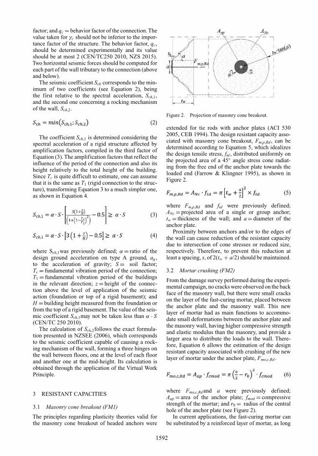
Figure 2. Projection of masonry cone breakout.
extended for tie rods with anchor plates (ACI 5302005, CEB 1994). The design resistant capacity asso-ciated with masonry cone breakout, Fm,p,Rd , can bedetermined according to Equation 5, which idealizesthe design tensile stress, ftd , distributed uniformly onthe projected area of a 45◦ angle stress cone radiat-ing from the free end of the anchor plate towards theloaded end (Farrow & Klingner 1995), as shown inFigure 2.
where Fm,p,Rd and ftd were previously defined;ANc = projected area of a single or group anchor;tw = thickness of the wall; and a = diameter of theanchor plate.
Proximity between anchors and/or to the edges ofthe wall can cause reduction of the resistant capacitydue to intersection of cone stresses or reduced size,respectively. Therefore, to prevent this reduction atleast a spacing, s, of 2(tw + a/2) should be maintained.
3.2 Mortar crushing (FM2)
From the damage survey performed during the experi-mental campaign, no cracks were observed on the backface of the masonry wall, but there were small crackson the layer of the fast-curing mortar, placed betweenthe anchor plate and the masonry wall. This newlayer of mortar had as main functions to accommo-date small deformations between the anchor plate andthe masonry wall, having higher compressive strengthand elastic modulus than the masonry, and provide alarger area to distribute the loads to the wall. There-fore, Equation 6 allows the estimation of the designresistant capacity associated with crushing of the newlayer of mortar under the anchor plate, Fmo,c,Rd .
where Fmo,c,Rdand a were previously defined;Aap = area of the anchor plate; fmod = compressivestrength of the mortar; and r0 = radius of the centralhole of the anchor plate (see Figure 2).
In current applications, the fast-curing mortar canbe substituted by a reinforced layer of mortar, as long
1592
as its area is wide enough to distribute stresses to thewall without causing permanent damage.
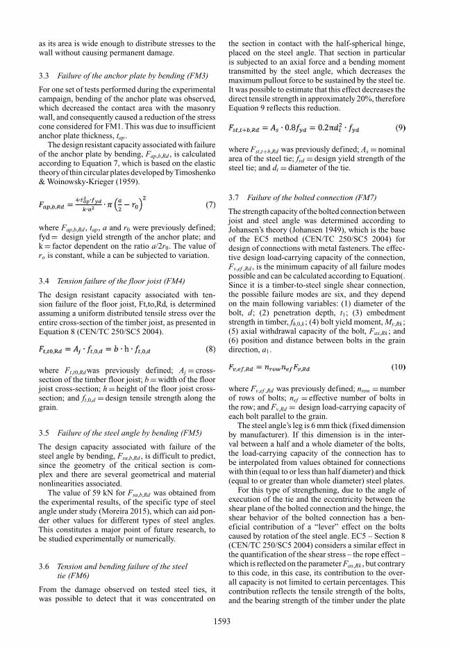
3.3 Failure of the anchor plate by bending (FM3)
For one set of tests performed during the experimentalcampaign, bending of the anchor plate was observed,which decreased the contact area with the masonrywall, and consequently caused a reduction of the stresscone considered for FM1. This was due to insufficientanchor plate thickness, tap.
The design resistant capacity associated with failureof the anchor plate by bending, Fap,b,Rd , is calculatedaccording to Equation 7, which is based on the elastictheory of thin circular plates developed byTimoshenko& Woinowsky-Krieger (1959).
where Fap,b,Rd , tap, a and r0 were previously defined;fyd = design yield strength of the anchor plate; andk = factor dependent on the ratio a/2r0. The value ofro is constant, while a can be subjected to variation.
3.4 Tension failure of the floor joist (FM4)
The design resistant capacity associated with ten-sion failure of the floor joist, Ft,to,Rd, is determinedassuming a uniform distributed tensile stress over theentire cross-section of the timber joist, as presented inEquation 8 (CEN/TC 250/SC5 2004).
where Ft,t0,Rdwas previously defined; Aj = cross-section of the timber floor joist; b = width of the floorjoist cross-section; h = height of the floor joist cross-section; and ft,0,d = design tensile strength along thegrain.
3.5 Failure of the steel angle by bending (FM5)
The design capacity associated with failure of thesteel angle by bending, Fsa,b,Rd , is difficult to predict,since the geometry of the critical section is com-plex and there are several geometrical and materialnonlinearities associated.
The value of 59 kN for Fsa,b,Rd was obtained fromthe experimental results, of the specific type of steelangle under study (Moreira 2015), which can aid pon-der other values for different types of steel angles.This constitutes a major point of future research, tobe studied experimentally or numerically.
3.6 Tension and bending failure of the steeltie (FM6)
From the damage observed on tested steel ties, itwas possible to detect that it was concentrated on
the section in contact with the half-spherical hinge,placed on the steel angle. That section in particularis subjected to an axial force and a bending momenttransmitted by the steel angle, which decreases themaximum pullout force to be sustained by the steel tie.It was possible to estimate that this effect decreases thedirect tensile strength in approximately 20%, thereforeEquation 9 reflects this reduction.
where Fst,t+b,Rd was previously defined; As = nominalarea of the steel tie; fyd = design yield strength of thesteel tie; and dt = diameter of the tie.
3.7 Failure of the bolted connection (FM7)
The strength capacity of the bolted connection betweenjoist and steel angle was determined according toJohansen’s theory (Johansen 1949), which is the baseof the EC5 method (CEN/TC 250/SC5 2004) fordesign of connections with metal fasteners. The effec-tive design load-carrying capacity of the connection,Fv,ef ,Rd , is the minimum capacity of all failure modespossible and can be calculated according to Equation(.Since it is a timber-to-steel single shear connection,the possible failure modes are six, and they dependon the main following variables: (1) diameter of thebolt, d; (2) penetration depth, t1; (3) embedmentstrength in timber, fh,0,k ; (4) bolt yield moment, My,Rk ;(5) axial withdrawal capacity of the bolt, Fax,Rk ; and(6) position and distance between bolts in the graindirection, a1.
where Fv,ef ,Rd was previously defined; nrow = numberof rows of bolts; nef = effective number of bolts inthe row; and Fv,Rd = design load-carrying capacity ofeach bolt parallel to the grain.
The steel angle’s leg is 6 mm thick (fixed dimensionby manufacturer). If this dimension is in the inter-val between a half and a whole diameter of the bolts,the load-carrying capacity of the connection has tobe interpolated from values obtained for connectionswith thin (equal to or less than half diameter) and thick(equal to or greater than whole diameter) steel plates.
For this type of strengthening, due to the angle ofexecution of the tie and the eccentricity between theshear plane of the bolted connection and the hinge, theshear behavior of the bolted connection has a ben-eficial contribution of a “lever” effect on the boltscaused by rotation of the steel angle. EC5 – Section 8(CEN/TC 250/SC5 2004) considers a similar effect inthe quantification of the shear stress – the rope effect –which is reflected on the parameter Fax,Rk , but contraryto this code, in this case, its contribution to the over-all capacity is not limited to certain percentages. Thiscontribution reflects the tensile strength of the bolts,and the bearing strength of the timber under the plate
1593

on the opposite side of the timber element, as shownin Equation 11.
where Fax,Rk and nrow were previously defined;n = total number of bolts; fyk = characteristic yieldstrength of the bolts; Api,net = area of the plate oppos-ing the steel angle, below the timber joist; andfc,90,k = characteristic compressive strength perpen-dicular to the grain.
4 DESIGN SEQUENCE
The design sequence proposed to the tension wall-diaphragm anchors is presented in 5 and initiates withthe calculation of the seismic demand on the con-nection per meter, Fch,d . The next step concerns theverification of the necessity to retrofit or not, by usingEquation 11. If true, the unstrengthened connectionhas enough capacity to resist the seismic demand andthere is no need to retrofit.
where Fch,d was defined previously; Furc,Rd = designresistant capacity of the unstrengthened connection;and sj = spacing between joists.
Considering the existing literature and the pull-out tests carried out on unstrengthened specimens,the design capacity of unstrengthened wall-diaphragmconnections, Furc,Rd , can take values between 2 kN and4 kN, depending on its configuration (Cóias e Silva2007, Moreira et al. 2012, Lin & LaFave 2012).
If retrofit is proven to be necessary, one proceedson the flowchart to the design of the different compo-nents of the strengthening solution. Two key aspectsof the design sequence are: to consider that the dis-tinct failure modes occur isolated and in series, whichis a simplified view of the overall performance of theconnections, and to establish that each of the designresistant capacities must be higher than the designseismic demand.
Using the formulae presented in Section 3, it is pos-sible to proceed with the design of certain geometricvariables, as shown in Figure 3. It goes without say-ing that these dimensions should be pondered withinreasonable values, aiming at optimization of resourcesand design. The mechanical properties of the stainlesssteel that constitute the different components of thestrengthening solution are considered fixed, thereforethey are not design variables. The values of Fsa,b,Rdare assumed to be provided by the manufacturer ofthe steel angle (research under development). Onlythe resistant capacities associated with failure modesFM4 and FM5 are subjected to verification instead ofdesign. While the latter can be iteratively adjusted, the
first, if not verified, terminates the flowchart, sinceimplicates major changes to the timber joist.
The minimum amount of anchors, n, and spacingbetween them, s, are obtained considering that theseismic demand is equally distributed through all thelength of the wall. It is recommended to first deter-mine s, which is at most equal to Fc,Rd divided byFch,d , taking into consideration the value of sj . Then,one determines n. If s is higher than sj , Fc,Rd shouldbe increased.
Tomaževiè (1999) suggests that s should be around1.5 m to 2.0 m, while in older applications of strength-ening, as for example with metal straps, this distancewas approximately 4 m. ASCE/SEI-41 (2014) consid-erers that the spacing between anchors should not behigher than 2.4 m (converted to one decimal place of8 ft).
5 APPLICATION EXAMPLE
The example presented here concerns a connectionbetween the 2nd and 3rd storey of an unreinforcedmasonry building with timber floors, as presented inFigure 4. The ground-floor and 1st floor have both3.0 m of height. In terms of materials, is consideredthat both masonry walls (each floor) have the samedesign properties, which are the following: density,ρd , of 2000 kg/m3 and tensile strength of 0.10 MPa.For the floor joists, it is considered that they have thefollowing characteristic properties: density ρk of 300,fc,90,k of 5.0 MPa, and ft,0,m of 10.0 MPa. The floorjoists are spaced of 0.40m and have a cross-section of0.08 × 0.20 m2.
The building is located in the 2.1 seismic zone,according to the National Annex of Portugal, ofEurocode 8-Part 1 (CEN/TC 250 2010) and belongsto the importance class number II. The soil belongs toclass C.
Considering the seismic zone and Equation 4, it ispossible to determine Sch,1 for each floor, as shownnext:
The calculation of Sch,2 follows the method sug-gested in section 2 and found in Section 10 of theNZSEE (2006). The main steps are briefly presentednext:
- 2nd storey:
1594

Figure 3. Design sequence of tension wall-diaphragmanchors.
Figure 4. Representation of a connection between twofloors, for exercise purposes.
For the estimation of P was considered a linearweight of 0.50 kN/m for the timber joist, 1 kN/m forother permanent loads, and 12 kN/m from the roof.
The values considered for the eccentricities shouldbe pondered according to the boundary conditions, andin this case the following were adapted.
Using the Principle ofVirtual Works, one can obtainb, as follows:
The value determined for the Sch,2of the 2nd flooris the one presented next:
For the 3rd floor, the same procedure was applied andthe of 0.28 g was obtained for Sch,2. The Sch adoptedfor each floor is the minimum of both the coefficients,which in this case is 0.52 g and 0.28 g, for the 2nd and3rd floors, respectively.
The design seismic force on the connection, assum-ing a γp of 1.0 and qp of 1.5 takes the value of 7.1 kN.The intermediate steps are:
Considering the spacing of 0.40 m and the valueobtained experimentally for Furc,Rd , 2.3 kN, oneobtains a linear force of approximately 5.8 kN/m,which is lower than Fch,total,d , meaning the connectionhas to be retrofitted.
Proceeding on the design sequence presented inFigure 3, the following steps regard the design ofsome parameters. In Table 1 are presented the designresults determined for the retrofit solution and in Fig-ure 5 is shown the distribution of the anchors on theconnections.
1595

Table 1. Results of the design sequence.
Anchor plate diameter, a 0.25 mAnchor plate thickness, tap 0.006 mTies diameter, dt ϕ12Bolted connection 4ϕ8Spacing, s 2.40 mNumber of anchors, n 4
Figure 5. Distribution of the wall-diaphragm anchorage.
6 CONCLUSIONS
The proposed design for the tension wall-diaphragmanchorage is one more step for the integrated approachto develop an “engineered strengthening”, whichstarted with the experimental campaign on the pro-totypes proposed by the company Monumenta Lda.
The proposed procedure is a force-based designmethod and aims at assisting practitioners on imple-menting a simplified calculation of the tensionanchors.
A quantification of the seismic demand on ten-sion anchors for linear procedures was proposed,comparing and adapting existing recommendationsfound on Eurocode 8 (CEN/TC250 2010), ASCE/SEI41-13, and NZSEE (2006) to the specificities ofwall-diaphragm connections.
Based on the existing literature and the experimen-tal results, it was possible to establish a set of possiblefailure modes and define their respective resistantcapacities formulae, which enable accurate design ofthe different components of the tension anchors.
Future works contemplate, as already mentioned,experimental and numerical campaigns to character-ize the behavior of the steel angle when subjectedto bending, and further development of the designmethodology, including application to case studies.
ACKNOWLEDGEMENTS
The authors would like to acknowledge ProfessorJason Ingham for providing essential information andtechnical expertise concerning the NZSEE (2006)application. This work was partially funded by projectFP7-ENV-2009-1-244123-NIKER of the 7th Frame-work Program of the European Commission, andby FCT, within ISISE, project UID/ECI/04029/2013,which are gratefully acknowledged.
REFERENCES
ACI 530, 2005. Building Code Requirements for MasonryStructures (ACI 530-05), Masonry Standars Joint Comit-tee.
ASCE, 2014. ASCE/SEI 41-13. Seismic Evaluation andRetrofit of Existing Buildings, USA.
Campbell, J. et al., 2012. Test results for extracted wall-to-diaphragm anchors from Christchurch unreinforcedmasonry buildings. SESOC Journal, 25(1), pp. 57–67.
CEB, 1994. Fastenings to Concrete and Masonry Structures.State-of-the-art report, London: Thomas Telford.
CEN/TC 250, 2010. EN 1998-1: 2010 Eurocode 8 - Designof structures for earthquake resistance. Part 1: Generalrules, seismic actions and rules for buildings.
CEN/TC 250/SC5, 2004. EN 1995-1-1:2004. Eurocode 5 –Design of timber structures - Part 1-1: General - Commonrules and rules for buildings, Brussels, Belgium.
Cóias e Silva, V., 2007. Reabilitação Estrutural de EdifíciosAntigos, Lisboa: Argumentum.
Farrow, C.B. & Klingner, R.E., 1995. Tensile Capacity ofAnchors with Partial or Overlapping Failure Surfaces:Evaluation of Existing Formulas on an LRFD Basis. ACIStructural Journal, 92(6), pp. 698–709.
Johansen, K.W., 1949. Theory of Timber Connections.International Association of Bridge and Structural Engi-neering, 9, pp. 249–262.
Lin, T.J. & LaFave, J.M., 2012. Experimental struc-tural behavior of wall-diaphragm connections for oldermasonry buildings. Construction and Building Materials,26, pp. 180–189.
Lourenço, P.B. et al., 2011. Analysis of Masonry Struc-tures Without Box Behavior. International Journal ofArchitectural Heritage, 5(4–5), pp. 369–382. Available at:http://www.tandfonline.com/doi/abs/10.1080/15583058.2010.528824.
Moreira, S. et al., 2014. Developing a seismic retrofittingsolution for wall-to-floor connections of URM build-ingswith wood diaphragms. In 9th International MasonryConference (9th IMC). Guimarães, Portugal.
Moreira, S. et al., 2012. Experimental study on the seismicbehavior of masonry wall-to-floor connections. In 15thWorld Conference on Earthquake Engineering.
Moreira, S., 2015. Seismic retrofit of masonry-to-timberconnections in historical constructions. University ofMinho.
1596

NZS, 2015. NZS 1170 . 5: 2004 Structural Design ActionsPart 5: Earthquake actions - New Zealand.
NZSEE, 2006. Assessment and Improvement of the Struc-tural Performance of Buildings in Earthquakes. Section10 Revision Seismic Assessment of Unreinforced MasonryBuildings.
Paganoni, S. & D’Ayala, D., 2014. Testing and design proce-dure for corner connections of masonry heritage buildingsstrengthened by metallic grouted anchors. EngineeringStructures, 70, pp. 278–293.
Senaldi, I. et al., 2014.The Effect of Stiffened Floor and RoofDiaphragms on the Experimental Seismic Response of a
Full-Scale Unreinforced Stone Masonry Building. Jour-nal of Earthquake Engineering, 18(3), pp. 407–443.Avail-able at: http://www.tandfonline.com/doi/abs/10.1080/13632469.2013.876946 [Accessed March 24, 2014].
Timoshenko, S. & Woinowsky-Krieger, S., 1959. Theoryof Plates and Shells Second Edi., McGraw-Hill BookCompany.
Tomaževic, M., 1999. Earthquake-resistant design ofmasonry buildings A. S. Elnashai & P. J. Dowling, eds.,Imperial College Press.
1597