Embed Size (px)
Citation preview
NUREG/CR-6733
A Baseline Risk-Informed, Performance-Based Approach for In Situ Leach Uranium Extraction Licensees
Center for Nuclear Waste Regulatory Analyses
U.S. Nuclear Regulatory Commission Office of Nuclear Material Safety and Safeguards
Washington, DC 20555-0001 .oG.o
SEI037
- 1 -
AVAILABILITY OF REFERENCE MATERIALS IN NRC PUBLICATIONS
NRC Reference Material
As of November 1999, you may electronically access NUREG-series publications and other NRC records at NRC's Public Electronic Reading Room at www.nrc.gov/NRC/ADAMS/index.html. Publicly released records include, to name a few, NUREG-series publications; Federal Register notices; applicant, licensee, and vendor documents and correspondence; NRC correspondence and internal memoranda; bulletins and information notices; inspection and investigative reports; licensee event reports; and Commission papers and their attachments.
NRC publications in the NUREG series, NRC regulations, and Title 10, Energy, in the Code of Federal Regulations may also be purchased from one of these two sources. 1. The Superintendent of Documents
U.S. Government Printing Office Mail Stop SSOP Washington, DC 20402-0001 Internet: bookstore.gpo.gov Telephone: 202-512-1800 Fax: 202-512-2250
2. The National Technical Information Service Springfield, VA 22161-0002 www.ntis.gov 1-800-553-6847 or, locally, 703-605-6000
A single copy of each NRC draft report for comment is available free, to the extent of supply, upon written request as follows: Address: Office of the Chief Information Officer,
Reproduction and Distribution Services Section
U.S. Nuclear Regulatory Commission Washington, DC 20555-0001
E-mail: [email protected] Facsimile: 301-415-2289
Some publications in the NUREG series that are posted at NRC's Web site address www. nrc.gov/NRC/NUREGS/indexnum.html are updated periodically and may differ from the last printed version. Although references to material found on a Web site bear the date the material was accessed, the material available on the date cited may subsequently be removed from the site.
Non-NRC Reference Material
Documents available from public and special technical libraries include all open literature items, such as books, journal articles, and transactions, Federal Register notices, Federal and State legislation, and congressional reports. Such documents as theses, dissertations, foreign reports and translations, and non-NRC conference proceedings may be purchased from their sponsoring organization.
Copies of industry codes and standards used in a substantive manner in the NRC regulatory process are maintained at
The NRC Technical Library Two White Flint North 11545 Rockville Pike Rockville, MD 20852-2738
These standards are available in the library for reference use by the public. Codes and standards are usually copyrighted and may be purchased from the originating organization or, if they are American National Standards, from
American National Standards Institute 11 West 42'n Street New York, NY 10036-8002 www.ansi.org 212-642-4900
Legally binding regulatory requirements are stated only in laws; NRC regulations; licenses, including technical specifications; or orders, not in NUREG-series publications. The views expressed in contractor-prepared publications in this series are not necessarily those of the NRC.
The NUREG series comprises (1) technical and administrative reports and books prepared by the staff (NUREG-XXXX) or agency contractors (NUREG/CR-XXXX), (2) proceedings of conferences (NUREG/CP-XXXX), (3) reports resulting from international agreements (NUREG/IA-XXXX), (4) brochures (NUREG/BR-XXXX), and (5) compilations of legal decisions and orders of the Commission and Atomic and Safety Licensing Boards and of Directors' decisions under Section 2.206 of NRC's regulations (NUREG-0750).
DISCLAIMER: This report was prepared as an account of work sponsored by an agency of the U.S. Government. Neither the U.S. Government nor any agency thereof, nor any employee, makes any warranty, expressed or implied, or assumes any legal liability or responsibility for any third party's use, or the results of such use, of any information, apparatus, product, or process disclosed in this publication, or represents that its use by such third party would not infringe privately owned rights.
- 2 -

NUREG/CR-6733
A Baseline Risk-Informed, Performance-Based Approach for In Situ Leach Uranium Extraction Licensees Manuscript Completed: June 2001 Published: September 2001
Prepared by P. C. Mackin, D. Daruwalla, J. Winterle, M. Smith, D. A. Pickettt
Center for Nuclear Waste Regulatory Analyses 6220 Culebra Road San Antonio, TX 78228-0510
M. Layton, NRC Project Manager
Prepared for Division of Fuel Cycle Safety and Safeguards Office of Nuclear Material Safety and Safeguards U.S. Nuclear Regulatory Commission Washington, DC 20555-0001 NRC Job Code J5220
- 3 -

NUREG/CR-6733 has been reproduced from the best available copy.
- 4 -

ABSTRACT
Existing U.S. Nuclear Regulatory Commission (NRC) regulations are not specifically applicable to uranium recovery facilities. Appendix A to 10 CFR Part 40 provides criteria for the operation of conventional uranium mills and for the disposition of their tailings or wastes; however, technology for in situ leaching (ISL) of uranium, which comprises the majority of current uranium extraction operations in the United States, for the most part evolved subsequent to the promulgation of 10 CFR Part 40.
The technology for the extraction of uranium using ISL techniques allows economical recovery of uranium from lower grade ores and causes less environmental disruption than conventional extraction and milling. The final stages of the ISL process produce yellowcake (U30.) using the same drying process employed by conventional uranium mills. Other aspects of the ISL process are substantially different from conventional uranium ore processing.
Current NRC regulations specifically applicable to uranium extraction at 10 CFR Part 40, Appendix A implement U.S. Environmental Protection Agency (EPA) regulations at 40 CFR Part 192. The current regulations address yellowcake drying and the wastes produced from ISL operations but do not govern other aspects of the ISL process, including the restoration of groundwater contaminated by these operations.
The NRC is implementing Direction Setting Issue 12 of its Strategic Reassessment and Rebaselining Initiative to employ risk-informed, performance-based (RIPB) regulatory programs that consider, among other factors, the degree of risk associated with specific operations in defining the nature of the applicable regulatory requirements. These regulatory programs typically identify performance measures as the basis for regulatory requirements.
The NRC staff tasked the Center for Nuclear Waste Regulatory Analyses (CNWRA) to develop a RIPB foundation for regulating ISL facilities. This report presents the results from that effort. The CNWRA used commonly accepted practices for hazard identification, consequence analysis, and risk assessment to define risks associated with ISL facility operations. The report examines operations for extracting and processing uranium into yellowcake, restoring groundwater quality subsequent to ore extraction, and health and environmental hazards and risks. Where possible, quantitative and probabilistic methods were used. The CNWRA used staff with expertise in dose assessment and health physics; process engineering; groundwater science and engineering; geochemistry; systems analysis and risk assessment; probabilistic and statistical analysis; identification, analysis, management, and evaluation of risk:; and NRC regulation of source and 1 e.(2) byproduct material to complete this assessment. The CNWRA also collaborated closely with NRC staff experienced in ISL facility licensing.
iii
- 5 -

CONTENTS
Section Page
A B STRA CT ........................................................................ iii FIG U R E S .......................................................................... ix TA B L E S .......................................................................... xi ACKNOW LEDGM ENTS ............................................................ xiii
INTRODUCTION ........................................................... 1-1
2 DESCRIPTION OF IN-SITU LEACH FACILITY OPERATIONS ...................... 2-1 2.1 URANIUM EXTRACTION FROM THE ORE BODY ........................ 2-1 2.2 OPERATIONS IN THE PROCESSING PLANT ............................. 2-6
2.2.1 Ion Exchange .................................................. 2-6 2.2.2 Elution ........................................................ 2-8 2.2.3 Precipitation and Drying .......................................... 2-8
2.3 AQUIFER RESTORATION ............................................. 2-9 2.3.1 Groundwater Sweep ............................................ 2-10 2.3.2 Reverse Osmosis with Permeate Injection ........................... 2-10 2.3.3 Recirculation .................................................. 2-12 2.3.4 Stabilization .................................................. 2-12
2.4 INSTRUMENTATION ................................................ 2-12 2.5 WASTE MANAGEMENT ............................................. 2-13
2.5.1 Liquid W aste Disposal .......................................... 2-13 2.5.2 Solid Effluent W aste Disposal .................................... 2-14 2.5.3 Gaseous Effluent and Airborne Particulate Waste Disposal ............. 2-14
2.6 RECLAMATION, DECONTAMINATION, AND DECOMMISSIONING ....... 2-15 2.7 MANAGEMENT CONTROLS AND OPERATING PROCEDURES ............ 2-17 2.8 RADIATION SAFETY CONTROLS AND MONITORING ................... 2-18
2.8.1 Gaseous and Airborne Particulate Effluent Controls ................... 2-18 2.8.2 Radioactive Liquid Effluent Controls ............................... 2-18 2.8.3 External Radiation Exposure Monitoring Program .................... 2-19 2.8.4 In-Plant Airborne Radiation Monitoring ............................ 2-20 2.8.5 Airborne Environmental Monitoring Programs ....................... 2-20 2.8.6 In-Plant Radon Daughter Surveys ................................. 2-20
2.9 RESPIRATORY PROTECTION PROGRAM .............................. 2-20 2.10 BIOASSAY PROGRAM ............................................... 2-21 2.11 CONTAMINATION CONTROL PROGRAMS ............................. 2-21 2.12 GROUNDWATER AND SURFACE WATER MONITORING PROGRAMS ..... 2-21
2.12.1 Groundwater Monitoring ........................................ 2-21 2.12.2 Surface W ater Monitoring ....................................... 2-22
2.13 MANAGEMENT AUDIT AND CONTROL PROGRAM ..................... 2-22 2.14 REPORTING REQUIREMENTS ........................................ 2-23
3 APPROACH TO RISK ASSESSMENT .......................................... 3-1 3.1 BACKGROUND ...................................................... 3-1 3.2 SURFACE ENVIRONMENT CHEMICAL HAZARDS ....................... 3-2
v
- 6 -

CONTENTS (continued)
Section Page
3.3 SURFACE ENVIRONMENT RADIOLOGICAL HAZARDS ................... 3-5 3.4 GROUNDWATER CHEMICAL AND RADIOLOGICAL CONTAMINATION
HAZARDS ......................................................... 3-6
4 CONSEQUENCE ANALYSES ................................................. 4-1 4.1 CHEMICAL HAZARD CONSEQUENCE ANALYSES ....................... 4-1
4.1.1 Hazard Analysis for Ammonia ..................................... 4-4 4.1.2 Hazard Analysis for Sulfuric Acid .................................. 4-5 4.1.3 Hazard Analysis for Oxygen ....................................... 4-7 4.1.4 Hazard Analysis for Hydrogen Peroxide ............................. 4-8 4.1.5 Hazard Analysis for Sodium Hydroxide .............................. 4-9 4.1.6 Hazard Analysis for Barium Chloride .............................. 4-10 4.1.7 Hazard Analysis for Carbon Dioxide ............................... 4-11 4.1.8 Hazard Analysis for Hydrochloric Acid ............................. 4-12 4.1.9 Hazard Analysis for Sodium Carbonate and Sodium Chloride ........... 4-14 4.1.10 Hazard Analysis for Hydrogen Sulfide and Sodium Sulfide ............. 4-15 4.1.11 General Consideration of Chemical Risk ............................ 4-16
4.2 RADIOLOGICAL HAZARD CONSEQUENCE ANALYSIS .................. 4-16 4.2.1 Thickener Failure and Spill ...................................... 4-16 4.2.2 Radon Release Consequence Analysis .............................. 4-27 4.2.3 External Consequence from Pregnant Lixiviant and Loaded Resin Spills . 4-31 4.2.4 Yellowcake Dryer Hazard Analysis ................................ 4-31
4.3 GROUNDWATER CONTAMINATION HAZARD CONSEQUENCE AN ALY SIS ......................................................... 4-35 4.3.1 Groundwater Protection Regulations for In Situ Leach Facilities ......... 4-35 4.3.2 Implementation of Groundwater Protection Requirements: Excursion
Control M onitoring ............................................. 4-36 4.3.3 Excursion Risk Analysis ......................................... 4-38
4.3.3.1 Source Zone Size, Location, and Persistence .................. 4-40 4.3.3.2 Lateral Spreading between Source Zone and Monitor Wells ...... 4-40 4.3.3.3 Monitor Well Locations and Spacing ........................ 4-43
4.3.4 Summary and Regulatory Considerations ........................... 4-44 4.4 PREGNANT LIXIVIANT FIELD SPILL HAZARD CONSEQUENCE
ANALY SIS ......................................................... 44 5 4.4.1 Pregnant Lixiviant Field Spill Consequence Analysis for Surface
Ponding ...................................................... 4-46 4.4.2 Pregnant Lixiviant Field Spill Consequence Analysis for Runoff to
Surface W ater ................................................. 4-4 9 4.4.3 Pregnant Lixiviant Field Spill Consequence Analysis for Retention
in Soil ....................................................... 4-50 4.4.4 Pregnant Lixiviant Field Spill Consequence Analysis for Transport to
Groundwater ........................................... 4-53 4.4.5 Assessment of Likelihood for a Pregnant Lixiviant Field Spill .......... 4-53
vi
- 7 -

CONTENTS (continued)
Section Page
4.4.6 Summary of Risk Significance for Pregnant Lixiviant Field Spill ......... 4-53 4.5 TRANSPORTATION HAZARD RISK ANALYSIS ......................... 4-53
4.5.1 Transportation Risk Analysis ..................................... 4-54 4.5.2 Safety Controls and Mitigating Actions for Transportation Hazards ....... 4-55 4.5.3 Summary of Risk Significance for Transportation Hazards .............. 4-55
4.6 TORNADO HAZARD AND CONSEQUENCE ANALYSIS .................. 4-55 4.7 SEISMIC HAZARD AND CONSEQUENCE ............................... 4-56 4.8 PERFORMANCE MEASURES ......................................... 4-57
5 RISK INSIGHTS AND RECOMMENDATIONS ................................... 5-1 5.1 CHEM ICAL RISK ..................................................... 5-1
5.1.1 Chemical Risk Insights ........................................... 5-1 5.1.2 Recommendation Regarding Chemical Risks ......................... 5-2
5.2 RADIOLOGICAL RISKS ............................................... 5-2 5.2.1 Radiological Risks Insights ....................................... 5-2 5.2.2 Recommendations Regarding Radiological Risks ...................... 5-3
5.3 GROUNDWATER CONTAMINATION RISKS ............................. 5-3 5.3.1 Groundwater Contamination Risks Insights ........................... 5-3 5.3.2 Recommendations Regarding Groundwater Contamination Risks ......... 5-4
5.4 PREGNANT LIXIVIANT FIELD SPILL RISKS ............................. 5-4 5.4.1 Pregnant Lixiviant Field Spill Risks Insights .......................... 5-5 5.4.2 Recommendations Regarding Pregnant Lixiviant Field Spill Risks ........ 5-5
5.5 TRANSPORTATION RISKS ............................................ 5-6 5.5.1 Transportation Risks Insights ...................................... 5-6 5.5.2 Recommendations Regarding Transportation Risks ..................... 5-6
5.6 TORNADO RISKS .................................................... 5-6 5.6.1 Tornado Risks Insights ........................................... 5-6 5.6.2 Recommendations Regarding Tornado Risks .......................... 5-7
5.7 SEISM IC RISKS ...................................................... 5-7 5.7.1 Seismic Risks Insights ........................................... 5-7 5.7.2 Recommendations Regarding Seismic Risks .......................... 5-7
5.8 SAFETY CONTROLS AND DEVICES .................................... 5-7 5.8.1 Safety Controls and Devices Risk Insights ............................ 5-7 5.8.2 Recommendations Regarding use of Safety Devices and Controls ......... 5-8
5.9 PERFORMANCE MEASURES .......................................... 5-8
6 REFERENCES .............................................................. 6-1
vii
- 8 -

CONTENTS (continued)
Section Page
APPENDIXES
A - MATERIAL SAFETY DATA SHEETS ................................... A-1 B - EXTERNAL DOSE ESTIMATE FOR STANDING NEAR THICKENER TANK.. B-1 C - EXTERNAL DOSE ESTIMATES FOR PREGNANT LIXIVIANT SPILL AND
PREGNANT LIXIVIANT SPILL CONTAINING LOADED RESIN ............ C-1 D - GENII VERSION 1.485 INPUT FILE USED TO COMPARE 226Ra AND
URANIUM TOTAL EFFECTIVE DOSE EQUIVALENT, AS REQUIRED BY 10 CFR PART 40, APPENDIX A, CRITERION 6-(6) ........................ D-1
E - EXAMPLE GENII VERSION 1.485 INPUT FILE FOR THE PERIOD 1 YR FOLLOW ING CLOSURE .............................................. E-1
viii
- 9 -

FIGURES
Figure Page
2-1 Simplified cross sections of roll-front uranium deposits formed by regional groundwater m igration ................................................................... 2-2
2-2 Idealized schematic cross section illustrating ore-zone geology and lixiviant migration from an injection well to a production well with no vertical or horizontal excursion ............ 2-3
2-3 Schematic diagram of a well field showing injection/production well patterns, monitor wells, manifold building, and pipelines ........................................... 2-5
2-4 Schematic flow diagram of an in situ leach uranium recovery process ................... 2-7 2-5 Aquifer restoration process schematic ........................................... 2-11
3-1 Approach to hazard identification and consequence assessment ........................ 3-3
4-1 Graphical representation of Eq. (4-4) showing how near-surface wind speed and spill area are used to determine the total volume of contaminated air removed from the spill site during a given time period ................................................. 4-20
4-2 A plot of the downwind doses at various x-distances (meters) (y = 0, z = 1 m) from a U30 8 spill, based on different airborne release durations (length of time that the U30, spill receives no mitigating action after drying to a point when airborne release is possible) .................................................................. 4-23
4-3 A plot showing opposing effects of average U30 8 concentration and release duration on dose at 0 m ................................................................ 4-24
4-4 A plot showing sensitivity of downwind dose to varying atmospheric stability classes for an 8-hr release duration ....................................................... 4-25
4-5 A plot showing sensitivity of downwind dose to varying 30-ft elevation wind speeds for an 8-hr release duration ............................................... 4-26
4-6 A plot showing sensitivity of downwind dose to varying wind directions for a 30-ft elevation wind speed of 4.7 m/s, stability class of B, and 8-hr release duration ........... 4-27
4-7 A plot showing sensitivity of downwind dose to varying spill sizes for a stability class B, 8-hr release duration, and 30-ft elevation wind speed of 4.7 m/s ....................... 4-28
4-8 Schematic illustration of a horizontal excursion monitoring ring showing a scenario where an excursion is detected (lower) and another where an excursion goes undetected (upper) (after Kasper et al., 1979) .............................................. 4-39
4-9 A plot of the top six contributors to dose for a maximally exposed individual living on a 240 in2 area contaminated with a pregnant lixiviant spill at times I yr, 3 yr, 5 yr, 10 yr, and 25 yr following closure of a facility .......................................... 4-52
ix
- 10 -

TABLES
Table Page
3-1 Summary of uranium in situ leach facility surface environment radiological consequence analyses .................................................................... 3-6
4-1 Pertinent regulations for the chemicals used at uranium in situ leach facilities ............. 4-2 4-2 Wind speed information for various cities within Nebraska, New Mexico, Texas, and
Wyoming from the National Climatic Data Center (2000) ........................... 4-19 4-3 Statistical summary of wind speed information presented in table 4-2 for various cities
within Nebraska, New Mexico, Texas, and Wyoming ............................... 4-20 4-4 Example reported 222Rn groundwater concentrations ................................ 4-29 4-5 Assumed activities used for pregnant lixiviant and loaded resin spill scenarios ........... 4-29 4-6 Typical scales for single production-injection patterns and spacings between horizontal and
vertical excursion monitor wells ................................................ 4-37 4-7 Highest contaminant levels in pregnant lixiviant from compiled documents ............. 4-47 4-8 Calculated external gamma dose-equivalent atop a pregnant lixiviant pond of infinite lateral
extent and depth ............................................................ 4-4 8 4-9 Radionuclide limits derived from 10 CFR Part 20, Appendix B: five times the lowest annual
limits on intake and water effluent concentration limits ............................. 4-49 4-10 Effluent concentration limits from subchapter N of 40 CFR Parts 400-471 .............. 4-50 4-11 The lower of two toxicity characteristic leaching procedure-based definitions of hazard level
in solid wastes from 40 CFR 261.24 and 40 CFR 268.48 ............................ 4-52
xi
- 11 -

ACKNOWLEDGMENTS
This report was prepared to document work performed by the Center for Nuclear Waste Regulatory Analyses (CNWRA) for the U.S. Nuclear Regulatory Commission (NRC) under Contract No. NRC-02-98-002. The activities reported here were performed on behalf of the NRC Office of Nuclear Material Safety and Safeguards, Division of Fuel Cycle Safety and Safeguards. This report is an independent product of the CNWRA, which does not necessarily reflect the views or regulatory position of the NRC. The authors thank D. Turner, and R. Benke, for their technical reviews and B. Sagar for his programmatic review. The authors are grateful for the secretarial support provided by L. Selvey.
QUALITY OF DATA, ANALYSES, AND CODE DEVELOPMENT
DATA: CNWRA-generated original data contained in this report meet quality assurance (QA) requirements described in the CNWRA Quality Assurance Manual. Sources for other data should be consulted for determining the level of quality for those data.
ANALYSES AND CODES: The software Environmental Simulation Program (ESP) Version 6.2 (OLI Systems, Inc., 1999) was used to calculate the solubility of radon in liquid phase at atmospheric pressure and the vapor pressures for several of the chemicals used in the uranium in-situ leach process. ESP is a commercial code, and only the object code is available to the CNWRA. ESP Version 6.2 is under CNWRA configuration control. A hardcopy of the ESP Version 6.2 input and output data used in the simulations is maintained in the CNWRA QA archives. The GENII Version 1.485 computer code (Napier et al., 1988) was used for analyses contained in this report. This computer code is controlled under the CNWRA software configuration procedures. CNWRA calculations and analyses supporting this report are documented in Scientific Notebook Nos. 398, 399, 400, and 405E.
xiii
- 12 -

1 INTRODUCTION
Existing U.S. Nuclear Regulatory Commission (NRC) regulations are not specifically applicable to uranium recovery facilities. Rather, Code of Federal Regulations Title 10, Part 40 (10 CFR Part 40), Domestic Licensing of Source Material, which applies broadly to all facilities receiving title to, receiving, possessing, using, transferring, or delivering source and byproduct materials, has been used for uranium recovery licensing. Appendix A to 10 CFR Part 40 provides criteria for the operation of conventional uranium mills and for the disposition of their tailings or wastes. Further, technology for in situ leaching (ISL) of uranium, which comprises the majority of current uranium extraction operations in the United States, for the most part evolved subsequent to the promulgation of 10 CFR Part 40.
The technology for the extraction of uranium using ISL techniques has developed as conventional uranium extraction and milling techniques have become less economical and environmentally unattractive. ISL technology allows economical recovery of uranium from lower grade ores and causes less environmental disruption than conventional extraction and milling. The final stages of the ISL process produce yellowcake (U30.) using the same drying process employed by conventional uranium mills. Other aspects of the ISL process are substantially different from conventional uranium ore processing.
Current NRC regulations specifically applicable to uranium extraction are at 10 CFR Part 40, Appendix A, Criteria Relating to the Operation of Uranium Mills and the Disposition of Tailings or Wastes Produced by the Extraction or Concentration of Source Material From Ores Processed Primarily for Their Source Material Content. This appendix implements U.S. Environmental Protection Agency (EPA) regulations at 40 CFR Part 192, Health and Environmental Protection Standards for Uranium and Thorium Mill Tailings. The regulatory requirements at 10 CFR Part 40 address yellowcake drying and the wastes produced from ISL operations but do not govern other aspects of the ISL process, including the restoration of groundwater contaminated by these operations. To address these deficiencies, NRC licenses for ISL facilities have established the requirements necessary to protect public health and safety and the environment through the imposition of license conditions.
Widespread use of license conditions is not an optimum regulatory framework. Since these license conditions are subject to rejection or modification through legal challenge, they add substantial uncertainty and economic and operational risk to ISL operations. Ensuring consistency of requirements for all licensees is also difficult with widespread use of license conditions. Consequently, the NRC is considering the preparation of new or updated regulatory guidance specifically for uranium recovery facilities that would incorporate requirements for ISL operations.
The Commission has provided the following direction to the staff on these new regulations (U.S. Nuclear Regulatory Commission, 2000a,b):
"* The staff should make any rulemaking plan available for comment.
"• All liquid effluents at ISL facilities, including evaporation pond sludges should be considered I1 e.(2) byproduct material.
"• Dual regulation of groundwater at ISL facilities will continue until such time that NRC can defer to EPA's Underground Injection Control (UIC) Program.
1-1
- 13 -

The NRC is implementing Direction Setting Issue 12 of its Strategic Reassessment and Rebaselining Initiative, which defines an agency-wide goal to employ risk-informed, performance-based (RIPB) licensing. Regulatory programs that are RIPB consider, among other factors, the degree of risk associated with specific operations in defining the nature of the applicable regulatory requirements. In general, operations that pose a high risk to public health and safety or the environment would be subject to more stringent regulatory requirements. Conversely, those operations that pose a low risk to public health and safety or the environment would be regulated less stringently. Risk considerations may also help determine which aspects of a facility should be regulated. RIPB regulatory programs typically identify performance measures as the basis for regulatory requirements.
To improve the regulatory framework for ISL facilities and to comply with Commission direction to implement RIPB regulatory programs (U.S. Nuclear Regulatory Commission, 1999a), the NRC staff tasked the Center for Nuclear Waste Regulatory Analyses (CNWRA) to provide technical assistance in developing a RIPB foundation for regulating ISL facilities. This report presents the results from that effort. The CNWRA used commonly accepted practices for hazard identification, consequence analysis, and risk assessment to define risks associated with ISL facility operations. The CNWRA assessment examined operations associated with extracting and processing uranium into yellowcake and restoring groundwater quality subsequent to ore extraction activities. The assessment included health and environmental hazards and risks. Where possible, quantitative and probabilistic methods were used; however, qualitative techniques were employed where necessary. The CNWRA used staff with expertise in dose assessment and health physics; process engineering; groundwater science and engineering; geochemistry; systems analysis and risk assessment; probabilistic and statistical analysis; identification, analysis, management, and evaluation of risk; and NRC regulation of source and 1 le.(2) byproduct material to complete this assessment. The CNWRA also collaborated closely with NRC staff experienced in ISL facility licensing. CNWRA staff visited two ISL facilities to gather information to support the analyses presented in this report.
Section 2 of this report provides a description of ISL facility operations. Section 3 presents the approach to risk assessment. Section 4 provides consequence analyses. Section 5 contains a summary of conclusions and recommendations, and section 6 lists references used in conducting the analyses and preparing the report.
1-2
- 14 -

2 DESCRIPTION OF IN-SITU LEACH FACILITY OPERATIONS
This description was derived from NUREG-1508, Final Environmental Impact Statement to Construct and Operate the Crown Point Uranium Solution Mining Project, Crown Point, New Mexico (U.S. Nuclear Regulatory Commission, 1997a); Crow Butte Uranium Project, Dawes County, Nebraska, Application for Renewal of USNRC Radioactive Source Materials License SUA-1534 (Crow Butte Resources, Inc., 1995); Supplemental Data for Renewal Source Material License SUA-143 1, Irigary and Christensen Ranch Projects (Cogema Mining, Inc., 1995); NUREG-1569, Draft Standard Review Plan for In Situ Leach Uranium Extraction License Applications (U.S. Nuclear Regulatory Commission, 1997b); and discussions with licensee and NRC staff experienced in ISL facility operation and regulation.
2.1 URANIUM EXTRACTION FROM THE ORE BODY
The ISL uranium extraction process involves three primary operations: uranium mobilization, uranium processing, and aquifer restoration. First, barren extraction solution (lixiviant), composed of groundwater enhanced by an oxidant and carbonate/bicarbonate, is injected through wells into the ore zone. This lixiviant moves through pores in the ore body and mobilizes uranium and other elements. The resulting "pregnant" lixiviant, which now contains uranium, is withdrawn by production wells and pumped to the processing plant. Then, uranium is extracted from the pregnant lixiviant by ion exchange in the processing plant, is dried to yellowcake form, and is packaged. Finally, groundwater that has been contaminated by the ore extraction process is cleaned up. More detailed descriptions of these operations are provided in subsequent sections of this report.
Uranium recovery using ISL techniques generally takes advantage of uranium mineralization in the form of roll fronts as shown in figure 2-1. These roll fronts are typically found at the edges of areas of altered sandstone. The roll fronts were created when preexisting uranium mineralization was oxidized and mobilized by dissolved oxygen contained in meteoric groundwater migrating through the sands. As groundwater oxygen was consumed, uranium and lesser amounts of other redox-sensitive metals, such as selenium and vanadium, were deposited at the interface between the oxidized and the reduced portions of the sands. Uranium-bearing fronts may not be present along the edges of all oxidized areas. They tend to concentrate in areas where physical and geochemical conditions are most favorable. Important factors controlling uranium deposition are the porosity, permeability, and geometry of the sands as well as the quantity of reducing agents such as pyrite and carbonaceous material present. The most common uranium ore minerals are uraninite (U0 2) and coffinite [U(SiO4)(OH)4]. Typically, minor quantities of tyuyamunite [Ca(UO2)2(VO4)2"H20] are also present. The ore-bearing sands are usually confined by semi-permeable layers. These semi-permeable units are key features to isolate the ore-producing horizon from overlying and underlying aquifers. Well field boundaries are defined by the licensee based on the geometry of the specific ore body.
During ISL operations, uranium is removed from the roll front by the lixiviant. Lixiviant is typically formed by adding an oxidant (oxygen gas or hydrogen peroxide) and sodium carbonate/bicarbonate to ore body groundwater. The sodium carbonate/bicarbonate (or occasionally carbon dioxide gas) contributes a carbonate complex to keep oxidized uranyl ion (UO2
2") in solution. Carbon dioxide can also be added for pH control. Lixiviant essentially reverses the geochemical reactions which initially caused deposition of the roll front. Lixiviant is pumped down injection wells to the mineralized zones where it oxidizes and dissolves uranium from the sandstone formation (figure 2-2). The uranium-bearing solution migrates through the pore spaces in the sandstone and is recovered in production wells. This pregnant lixiviant is pumped to the
2-1
- 15 -

Infi
ltra
tion
Wal
er
Tab
le
App
rox.
0.0
5.0
.25%
U
rani
um O
re
VIV
O
Ilnn
.
Con
fini
ng M
udat
one
Fig
ure
2-1.
Sim
plif
ied
cros
s se
ctio
n of
rol
l-fr
ont
uran
ium
dep
osit
s fo
rmed
by
regi
onal
gro
undw
ater
mig
rati
on (
U.S
. N
ucle
ar
Reg
ulat
ory
Com
mis
sion
, 19
97a)
- 16 -

Inje
ctio
n
i~iii
il ii'
iOre
Ba
rn
Pert
orat
ions
•.-
'
00
pe
rforat
ions.•
ii••ii
ii!.!•
i
--
--
-- -
--
--
--
--
---
---
-
----------
Les
s Pe
rmea
bleS
trat
a---
----
----
Fig
ure
2-2.
Ide
aliz
ed s
chem
atic
cro
ss s
ectio
n il
lust
rati
ng o
re-z
one
geol
ogy
and
lixiv
lant
mig
ratio
n fr
om a
n in
ject
ion
wel
l to
a pr
oduc
tion
wel
l w
ith n
o ve
rtic
al o
r ho
rizo
ntal
exc
ursi
on (
U.S
. N
ucle
ar R
egul
ator
y C
omm
issi
on,
1997
a)
- 17 -

processing plant. In the processing plant, the uranium is extracted, the barren lixiviant is recharged, and the solution is returned through the injection pumps to dissolve additional uranium. This process is continued until the licensee determines that further uranium extraction is uneconomical.
The principal geochemical reactions caused by the lixiviant are the oxidation and resulting mobilization of uranium. Adding oxygen or hydrogen peroxide to the lixiviant oxidizes uranium from the relatively insoluble tetravalent state (U4÷) to the more soluble hexavalent state (UO2
2+). The typical reaction in Eq. (2-1) is
2(UO2 )(solid) + 0 2 (dissolved oxygen) = 2(UO 3) (2-1)
Once the uranium is in the +6 valence state, the complexing agent (typically bicarbonate) in the lixiviant drives the dissolution and mobilization of the uranium. Although uranium aqueous chemistry is complex, typical reactions [Eqs. (2-2) and (2-3)] in the ore body may include
U0 3 + 2(MHCO 3) = M 2UO 2 (CO 3) 2 + H 2 0, and (2-2)
U0 3 + D(HC0 3)2 = DUO 2(CO3)2 + H 2 0 (2-3)
where M and D are any monovalent and divalent cations, respectively.
During the uranium extraction process, ore body groundwater will become enriched in uranium and other redox-sensitive metals that are typically associated with uranium in nature. The most common metals are arsenic, selenium, vanadium, iron, manganese, and radium. These, and other contaminants such as chloride, must be removed from the groundwater after uranium extraction is completed to restore the groundwater to preextraction quality. Groundwater restoration will be addressed in more detail in subsequent discussion.
During uranium extraction operations, injection and production well patterns are established to support efficient ore recovery. A typical well arrangement is shown in figure 2-3. The well pattern installation at a given deposit is based on the geometry of the ore body. Various shapes are used, although five spot, alternative line drives, and staggered line drives are common. Since the ore bodies normally have irregular shapes, some of the well patterns are irregular. The production wells are normally positioned to pump pregnant lixiviant from a number of injection wells. Additionally, in the processing plant, a small (typically about 1-3 percent) bleed is removed from the process circuit as discussed in section 2.5.1 of this report to ensure that there is a net inflow of groundwater to the well field. This net inflow helps protect against vertical and horizontal excursions of lixiviant, and its associated contaminants, out of the well field. These excursions cause unintended contamination of the local groundwater, and license conditions require that they be reported to the NRC and cleaned up. Faulty wells and open exploration boreholes can be the cause of lixiviant excursions in the overlying and underlying aquifers, and all wells are subjected to periodic integrity tests.
Licensees use monitoring wells to help identify lixiviant excursions. Within the ore body, monitoring wells are installed around the perimeter of the well field to detect horizontal excursions within the ore body aquifer. These monitoring wells should be close enough to the well field to detect excursions quickly, but far enough away to avoid erroneous detections. They should be spaced close enough horizontally so that an excursion plume will intersect at least one monitoring well. Typical placement calls for the
2-4
- 18 -

A ARecovery Trunkline
AEdge of
Wellfield Area
A
. Injection/Recovery Wells
Ore Zone Monitor Wells
Shallow Zone Monitor Wells (One Per 4 Acres)
AA
Inset: 5-Spot Pattern
/ '. 1'N. " ...•- t
i -... . 1/ -,/
Groundwater Flow
Figure 2-3. Schematic diagram of a well field showing injection/production well patterns, monitor wells, manifold building, and pipelines (U.S. Nuclear Regulatory Commission, 1997a)
2-5
ABuiling
A
A 0
- 19 -

monitoring wells to be about 121.9 m (400 ft) from the perimeter of the well field with a horizontal spacing of 121.9 to 182.9 m (400 to 600 ft) between monitoring wells. The specific spacing and location of the monitoring wells is typically established by license condition and is often modified in consideration of site specific knowledge of the hydrogeologic characteristics of the ore body and the ease with which excursions can be detected and cleaned up.
Licensees are also required to establish monitor wells in overlying and underlying aquifers to detect vertical excursions. Historically, these monitoring wells are more widely spaced than those within the ore body aquifer, although underlying aquifer monitoring wells may not be required under some circumstances. General guidelines for placement of these monitoring wells have been (i) one monitor well per 1.6 ha (4 acres) of well field in the first overlying aquifer, (ii) one monitor well per 3.2 ha (8 acres) in each higher aquifer, and (iii) one monitor well per 1.6 to 3.2 ha (4 to 8 acres) in the underlying aquifer. These monitoring wells are typically sampled every 2 wk during operations. Section 2.12 of this report provides a detailed discussion of groundwater monitoring. This monitoring is used in conjunction with well integrity testing to identify and mitigate the occurrence of vertical excursions.
Pregnant lixiviant is pumped from the well fields to the processing plant by submersible pumps located in each production well. In some cases, booster pumps are installed in the lines to the processing plants. Depending on site-specific environmental conditions (e.g., seasonal temperature), the main injection and production lines to the processing plants may either run on the ground surface or be buried up to several feet to prevent freezing. These lines are usually 10.2- to 35.6-cm (4- to 14-in.) high density polyethylene or polyvinyl chloride pipes. The pregnant lixiviant is enriched in uranium relative to groundwater [typically about 5 x 10⁻⁴ lb/gal. (60 mg/L)] and is also likely to contain the trace elements and contaminants discussed previously.
2.2 OPERATIONS IN THE PROCESSING PLANT
Generally, the processing plant contains three fluid circuits: ion exchange, elution, and precipitation and drying (figure 2-4). Each of these is described separately in the following text.
2.2.1 Ion Exchange
As pregnant lixiviant from the production wells enters the ion exchange circuit, it may either be stored in a surge tank or sent directly to ion exchange columns. In the ion exchange columns, the uranium is absorbed onto uranium-selective resin beads. The primary reaction is the exchange of the uranium carbonate anionic complex for chloride ions, which become the source of higher chloride levels in the ore body. This happens because the (now barren) lixiviant exits the ion exchange columns, is recharged with oxidant and bicarbonate, and is returned to the well field for further extraction of uranium. The ion exchange reaction [Eq. (2-4)] is
2R(CI) + 2Na÷ + UO 2 (CO 3 )2 = R 2U0 2 (CO 3 )2 + 2NaC1 (2-4)
where R is the resin ion exchange site.
More fluid is extracted from the well field than is returned to the well field. This maintains a negative pressure gradient which causes the groundwater from the surrounding area to flow towards the ore
2-6
- 20 -

YE
LL
OW
CA
KE
RE
CO
VE
RY
UR
AN
IUM
EX
TR
AC
TIO
N
Fig
ure
2-4.
Sch
emat
ic f
low
dia
gram
of a
n in
situ
leac
h ur
aniu
m r
ecov
ery
proc
ess
(U.S
. Nuc
lear
Reg
ulat
ory
Com
mis
sion
, 19
97&
)
tFJ
- 21 -

_I
zone, thus containing the lixiviant within the desired ore-bearing region. This production bleed (typically about 1-3 percent) is removed downstream of the ion exchange columns, prior to reinjection of the barren lixiviant into the well field (see figure 2-4).
When the ion exchange columns become saturated with uranium, they are taken off line, and other columns are brought on line. Some facilities (termed satellite facilities) cannot process the ion exchange resins further. In these facilities, the resin is discharged to a truck and is then transported to a facility that has the capacity for further processing. These trucks are generally sole-use trucks that are placarded for this purpose in accordance with U.S. Department of Transportation requirements and NRC regulations at 10 CFR Part 7 1. Later sections of this report assesses the hazards associated with transferring and transporting loaded ion exchange resin.
2.2.2 Elution
In those ISL facilities that can process resin, after the resin is loaded with uranium, it enters the elution circuit. In the elution circuit, the uranium is washed from the resin, and the resin is made available for further cycles of uranium absorption. The resin may be eluted directly in the ion exchange column, or it may be transferred to a separate elution tank. In the elution process, the uranium is removed from the resin by flushing with a concentrated brine solution. This process returns Cl ions to the resin exchange sites, regenerating the resin at the same time that the uranium is released for further processing. A sodium carbonate or bicarbonate rinse is also used during this phase to keep the stripped uranium from precipitating in the elution vessel. The resulting uranium-rich solution is termed pregnant or rich eluant typically contains 0.067 lb/gal. (8 to 20 g/L). It is normally discharged to a holding tank. After a sufficient quantity of pregnant eluant is obtained, it is moved to the precipitation and drying circuit.
2.2.3 Precipitation and Drying
In the precipitation and drying circuit, the pregnant eluant is acidified using hydrochloric or sulfuric acid to destroy the uranyl carbonate complex. Hydrogen peroxide (H202) is then added to precipitate the uranium as uranyl peroxide (UO202). Caustic soda (NaOH) or ammonia (NH3) is also normally added at this stage to neutralize the acid remaining in the eluate. The (now barren) eluant is typically recycled. Water left over from these processes may be reused in the eluant circuit or may be managed as waste water. Waste water management is addressed in a subsequent section.
After the precipitation process, the resulting slurry is sent to a thickener where it is settled, washed, filtered, and dewatered. At this point, the slurry is 30 to 50 percent solids. This thickened slurry may be transported to a uranium processing plant to produce yellowcake (U30.), or it may be dried and packaged onsite.
For on-site processing, the slurry is next dried in the yellowcake dryer. Two kinds of yellowcake dryer are used: multihearth dryers and vacuum dryers. Older plants use gas-fired multihearth dryers. These dryers typically dry the yellowcake at about 400 to 620 'C (750 to 1,150 'F). Because of the high temperatures involved, any organic contaminants in the yellowcake (e.g., grease from bearings) will be completely burned and will exit the system with the dryer offgas. This is advantageous because left over organic residues in the packaged yellowcake product may oxidize while in the drum, leading to pressurization and bursting of the drum due to evolution of gases (primarily CO2) in the drum (U.S. Nuclear Regulatory Commission, 1999b). The offgas discharge from the dryer is scrubbed with a high intensity venturi scrubber
2-8
- 22 -

that has a 95 to 99 percent efficiency for removal of uranium particulates prior to release to the atmosphere. Solutions from the scrubber are normally returned to the precipitation circuit and are processed to recover any uranium particulates. As a result, the stack discharge normally contains only water vapor and quantities of uranium fines that are well below regulatory limits.
Newer plants usually employ vacuum yellowcake dryers. In a vacuum dryer, the heating system is isolated from the yellowcake so that no radioactive materials are entrained in the heating system or its exhaust. The drying chamber that contains the yellowcake slurry is under vacuum. Therefore, any potential leak would cause air to flow into the chamber, and the drying can take place at relatively low temperature [e.g., 149°C (250 °F)]. Moisture in the yelloweake is the only source of vapor. Emissions from the drying chamber are normally treated in two ways. First, vapor is passed through a bag filter to remove yellowcake particulates with an efficiency in excess of 99 percent. Any captured particulates are returned to the drying chamber. Then, any water vapor exiting the drying chamber is cooled and condensed. This process captures virtually all escaping particles.
The dried product (yellowcake) exits the bottom of the dryer into drums for packaging and shipping. The packaging area normally has a baghouse dust collection system to protect personnel and to minimize release of the yellowcake. Air from the baghouse dust collection system is typically routed to the dryer offgas line and scrubber. During drum loading, the drum is normally kept under negative pressure via a drum hood with a suction line. The drum hood transports any released particulates to a baghouse dust collector. The filtered air from this baghouse joins the dryer offgas and is passed through the scrubber. Parameters important to the effective operation of the dryer must be monitored, and existing NRC regulations at 10 CFR Part 40, Appendix A, Criterion (8), prohibit dryer operations when these parameters are outside prescribed ranges. After the dried product is cooled, it is packaged in 208 L (55-gal.) drums for shipment.
2.3 AQUIFER RESTORATION
The purpose of aquifer restoration within the well field is to assure the water quality and groundwater use adjacent to the well field will not be adversely affected by the uranium extraction operation. The portion of the aquifer designated for uranium extraction is exempted from regulatory protection by the EPA, in accordance with the Safe Drinking Water Act. However, groundwater adjacent to the exempted portion of the aquifer must still be protected. States authorized to implement the EPA groundwater protection program and the NRC use well field restoration as one method for protecting human health and environment.
Before beginning ore extraction, the licensee establishes baseline groundwater quality in selected wells in the production zone, in perimeter monitoring wells, and in monitoring wells in overlying and underlying aquifers, as described in NUREG-1569 (U.S. Nuclear Regulatory Commission, 1997b). Generally, groundwater quality restoration criteria are established on a parameter-by-parameter basis. The primary goal of aquifer restoration is to return all parameters to the average preextraction baseline conditions. If this goal can not be met with reasonable restoration efforts, the secondary goal is to return water quality to the maximum concentration limits specified in EPA primary and secondary drinking water regulations. For uranium, a concentration of 300 pCi/L (0.44 mg/L) has been used: this standard is based on requirements at 10 CFR Part 20 and is suitable for unrestricted release of natural uranium to water. Other uranium values may also be suitable, depending on pre-extraction water use that can be supported by the adjacent groundwater.
2-9
- 23 -

After uranium extraction is completed, the groundwater contains contaminants that were mobilized by the lixiviant. Licensees are to begin aquifer restoration in each extraction unit as the extraction operations end. This shortens the period of groundwater contamination. The contaminants currently must be cleaned up to standards specified by license conditions in each operating license. Groundwater restoration programs typically employ (i) groundwater sweep, (ii) reverse osmosis with permeate injection, (iii) groundwater recirculation, and (iv) stabilization monitoring. A description of each of these follows.
2.3.1 Groundwater Sweep
During groundwater sweep, water is pumped from the well field to the processing plant through all production and injection wells without reinjection, drawing native groundwater inward to flush the contaminants from areas that have been affected by the horizontal spreading (flaring) of contaminants in the affected zone during ore extraction. The intent of this process is to begin restoring the water quality. Generally, groundwater sweep is planned to reduce the conductivity, a total dissolved solids indicator, by about 25 percent in the well field. Water removed from the well field during this phase is typically treated for removal of uranium, 22Ra, and dissolved solids by reverse osmosis prior to discharge under an appropriate permit (reverse osmosis is discussed in more detail in subsequent text). A typical groundwater sweep process is depicted in figure 2-5. In the processing plant, the solution is filtered to remove suspended solids and is then pumped through an ion exchange column to remove uranium. The resulting fluid may be treated to purify it further, may be reinjected to the well field to assist in aquifer restoration, or may be disposed by one of the NRC-approved methods discussed in subsequent sections. The fluid is often placed in a lined evaporation pond where it is treated with barium chloride (BaCl.) to remove 95 to 99 percent of the 226Ra. The result is a barium/. 6Ra sulfate precipitate. This sludge is disposed as 1 e.(2) byproduct material, normally in a uranium mill tailings impoundment that is licensed for such disposal. Reverse osmosis may be combined with groundwater sweep.
2.3.2 Reverse Osmosis with Permeate Injection
After (and sometimes during) groundwater sweep operations, reverse osmosis/permeate injection is used. The goal of this phase is to return total dissolved solids, trace metal concentrations, and aquifer pH to baseline values. During reverse osmosis/permeate injection, chemical constituents are removed from the groundwater by passing it through a pressurized, semi-permeable membrane that yields two fluids: clean water (permeate: about 70 percent) and water with concentrated ions (brine: about 30 percent). The permeate is reinjected to the well field. Brine resulting from the reverse osmosis process is either pumped to an evaporation pond or is processed again through a brine concentrator. The brine concentrator heats and evaporates the water, concentrating the brine, which then contains precipitated solids in the form of common salts. The brine concentration process typically results in about one part briny slurry and salts and 300 parts purified wastewater. The briny slurry is then pumped to an evaporation pond for treatment and surface discharge, to other ponds for evaporation, or to deep disposal. Since about 30 percent of the water pumped from the well field during reverse osmosis/permeate injection is not returned, there will be a continuous introduction of clean native groundwater to the well field, which will help in aquifer restoration. Figure 2-5 shows a typical reverse osmosis/permeate injection process. Often, the reverse osmosis/permeate injection process is effective enough at removing uranium and 226Ra that further treatment for these constituents is not required. Antiscalants must be added to the groundwater upstream of the reverse osmosis unit to prevent fouling the membranes. Typically, sodium hexametaphosphate or polycarboxylic acid are used for this purpose. Sulfuric acid is normally added to provide the proper pH for reverse osmosis. After reverse osmosis, pH must be readjusted to match baseline pH levels by addition of sodium hydroxide.
2-10
I- 24 -

101,
I AN
K
Figu
re 2
-5. A
quif
er r
esto
rati
on p
roce
ss s
chem
atic
(U
.S.
Nuc
lear
Reg
ulat
ory
Com
mis
sion
, 19
97a)
wA
S IC
1A
W~I
I-.
OP
IIt*
4AL
f It
I(R
I A
ND
<•_ ,-
...
P
t KA
,-
- 25 -

Another important process in aquifer restoration is metals reduction. During ore extraction, the state is allowed to persist after ore extraction, metals and other constituents will continue to leach and will remain at high levels. Therefore, the preextraction oxidation state should be reestablished. This is typically achieved by the addition of an oxygen scavenger or reducing agent such as hydrogen sulfide (H2S) after the first well field pore volume of permeate has been injected.
2.3.3 Recirculation
After completion of the reverse osmosis/permeate injection phase, the well field water will have characteristics similar to those of the permeate, and the recirculation phase takes place. To produce a more even distribution of aquifer properties, well field water is circulated using the original injection and production wells. The quantity of water that is recirculated is dependent on site-specific parameters and contaminant levels. Recirculation ends the active aquifer restoration.
2.3.4 Stabilization
The final phase of aquifer restoration is stabilization. During this period, aquifer water is typically monitored by quarterly sampling to ensure that baseline or preextraction class-of-use conditions have been permanently restored and that there is no impact on any adjacent nonexempt aquifer. Aquifer restoration is reinitiated if determined to be necessary as a result of stabilization monitoring.
2.4 INSTRUMENTATION
Instrumentation supporting ISL operations varies among facilities. Typical instrumentation includes continuous pressure monitoring on both the injection and production piping and audible alarms to give indication of leaks or ruptures. In some plants, a pressure controller located downstream of the injection pumps maintains proper injection pressure. In most facilities, pressures and flow rates in each injection and production line can be monitored at well houses in the field or at a central operating station. Instrumentation can also include pH indicators and tank level indicators. Typical examples of alarms include the following:
"• Elution pump stop "* Main recovery line high and low pressure "* Main injection line high and low pressure "* Yellow cake dryer conditions such as
- Drum high level - Scrubber high and low recirculation flow - Scrubber water level - Scrubber air pressure - Combustion air failure - Shaft cooling failure - Main fuel status - Delumper high or low torque - Burner flame failure - Shaft stop - Shaft high temperature - Furnace low temperature
2-12
- 26 -

Instrumentation is backed up by operator presence in the processing facility and by routine tours and inspection of well field areas. Operator inspection frequency is typically established on a case-by-case basis through license conditions. Specific requirements for monitoring and operability of yellowcake drying equipment are contained in current NRC regulations at 10 CFR Part 40, Appendix A.
2.5 WASTE MANAGEMENT
2.5.1 Liquid Waste Disposal
Liquid effluents are generated during both ore extraction and aquifer restoration. During operations, one liquid effluent stream is a process bleed that is typically about 1-3 percent of the process flow rate. This bleed may be disposed via permitted deep injection, in a lined evaporation pond, or by passage through a reverse osmosis unit followed by discharge to the surface. Other liquid effluent streams are from sand filter backwash, resin transfer wash, and plant wash down. These other liquid wastes typically are disposed in lined evaporation ponds or to deep well injection.
Most uranium ISL facilities have concrete curbed floors equipped with floor drains and a sump to control and retain water from spills and washdowns. The sumps are normally equipped with pumps that can transfer liquids to lined evaporation ponds or return them to the process circuit. Most chemical tanks have berms that can hold their contents should they rupture.
Waste fluids may be disposed in waste retention ponds. These ponds facilitate evaporative removal of water that cannot be discharged to the environment. They also concentrate and control source and 1 le.(2) byproduct material that may be in the liquid effluents. In some cases, these waste retention ponds store wastes until they can be disposed elsewhere. Requirements for constructing, operating, and monitoring these ponds for leakage are specified in existing NRC regulations at 10 CFR Part 40, Appendix A.
During operations, the primary source of liquid effluents is the process bleed that minimizes the likelihood of well field excursions by ensuring a net inflow of clean groundwater to the well field. This process bleed is typically about 1-3 percent of the total process flow and is a few tens of gallons per minute. The process bleed is often treated to remove radium, and additional treatment is often provided to concentrate other contaminants in a smaller volume ofwastewater. The purified water is normally returned to the process circuit, and the remainder is disposed using an NRC-approved method. There are also small and intermittent waste streams. These wastes are often collected and concentrated or treated to reduce waste quantities in a component such as a brine concentrator prior to disposal.
Uranium ISL facilities have used various methods to dispose liquid waste streams. These methods include evaporation in ponds, deep well injection, land application, and surface discharge under a National Pollution Discharge Elimination System (NPDES).
Disposal in evaporation ponds and deep injection wells are the most frequently used methods for wastewater streams. Evaporation ponds have specific requirements in existing NRC regulations at 10 CFR Part 40, Appendix A. The land that they cover is significantly disturbed and may require decontamination at decommissioning. These ponds must have leak detection systems. Ultimately, the sludge from these ponds is disposed at licensed 1 le.(2) byproduct material disposal sites.
2-13
- 27 -

Deep well injection is also used frequently as a wastewater disposal method at uranium ISL facilities. Deep injection wells typically extend below 1,524 m (5,000 ft), well below any usable aquifer, and are typically in areas where the groundwater is not suitable for drinking. Reverse osmosis brine is often injected into these wells. Deep well injection requires an injection permit granted by EPA or the appropriate state regulatory agency, as well as approval from the NRC.
Land application is a wastewater disposal method that distributes the water over a relatively large area of land. Any wastewater disposed in this method must have uranium and radium removed to avoid contamination of surface soils or plants. Land application is less frequently used and also necessitates compliance with irrigation standards or water use standards of applicable agencies.
Surface discharge of waste waters has only been used for disposing treated water. Concentrations of radionuclides in wastewaters disposed using this method must meet NRC regulatory standards. Nonradiological constituents must meet acceptable limits for surface water discharge.
2.5.2 Solid Effluent Waste Disposal
Solid wastes normally consist of spent resin, empty chemical containers, miscellaneous pipes and fittings, contaminated sludge in ponds, tank sediments, and domestic trash. These wastes are classified as contaminated or noncontaminated based on their radiological characteristics. Noncontaminated wastes are disposed consistent with requirements for ordinary trash.
Solid residues from sand filter systems, tank sediments, and sump sediments that result from the process stream will remain in the lined evaporation ponds until decommissioning. These wastes are 1 le.(2) byproduct material and are disposed in an NRC-licensed disposal facility.
Evaporation pond sludges and sediments will contain extraction process chemicals and radionuclides. Dust and dirt are likely to have blown into the pond during its life and increased the volume of sludges. During removal of these sludges, dust abatement techniques are used to minimize worker exposure. Sludges are 11 e.(2) byproduct material and are disposed in a facility licensed for these materials.
Equipment from the processing plants is handled in one of three ways. Contaminated equipment may be dismantled and sold or transferred to another licensed facility. If properly decontaminated, this material could be sold for reuse, salvage, or scrap. Decontaminated materials that have no resale value, such as building foundations, may be removed for disposal elsewhere or buried onsite. Waste materials that cannot be decontaminated are disposed in an NRC-licensed facility. Reclamation, decontamination, and decommissioning are discussed in more detail in section 2.6 of this report.
2.5.3 Gaseous Effluent and Airborne Particulate Waste Disposal
Historically, gaseous emissions from uranium ISL extraction operations are significantly lower than those from conventional mills. ISL operations produce airborne effluents as gaseous emissions and as airbome particulates resulting from lixiviant circulation and yellowcake drying.
Radon gas is normally present in lixiviant at fairly high concentration. At pressurized ISL facilities, most of the radon will remain in solution. However, radon may escape from the processing circuit through vents or leaks or when transferring resin for transport from a satellite facility to a main processing
2-14
- 28 -

plant. Hazards from radon gas are usually addressed in one of two ways. In areas of the country where the processing plant may be open to outside air, any escaping radon gas is rapidly dissipated in the environment. In areas where the processing facilities must be indoors due to local climate conditions, a closed, pressurized processing plant is normally used. Excess vapor pressure from dissolution of radon and carbon dioxide or oxygen in the lixiviant is normally vented by relief valves piped to outside locations. Radon release from the processing plant can occur when ion exchange columns are opened for resin transfer or elution. Any such releases rely on the processing building ventilation system for removal, and concentrations of radioactive materials in internal or external gaseous effluent releases must meet the requirements at 10 CFR Part 20.
Radioactive particulate releases, if they occur, are likely to be associated with yellowcake drying and packaging operations. Other particulate emissions from the processing facility are primarily in the form of soda ash (Na2CO3), which is used to generate the sodium bicarbonate for lixiviant makeup. Normally there are baghouse dust collection systems that capture over 99 percent of the particulate emissions that arise from filling the soda ash storage containers. Baghouse dusts are returned to the system. A typical estimate for the releases from this source is 2 tons/yr.
Spills of radioactive liquids that are allowed to dry before they are cleaned up could be a source of air particulates and pose an inhalation hazard.
2.6 RECLAMATION, DECONTAMINATION, AND DECOMMISSIONING
Decommissioning normally takes place in accordance with an approved decommissioning plan. Typical decommissioning activities include
"* Plugging and abandoning wells
"• Conducting radiological surveys of facilities, process equipment, and materials to evaluate the potential for exposure during decommissioning
"• Removing contaminated equipment and materials to an approved disposal facility or reusing
them
"• Decontaminating items to be released for unrestricted use
"* Surveying excavated areas for contamination and removing any contamination
"• Backfilling and recontouring disturbed areas
"* Performing final site soil radiation background surveys
"* Revegetating disturbed areas
Process buildings and equipment are surveyed to identify any radiation hazards. Most buildings and equipment are expected to be reusable. Alternatives for handling process buildings and equipment include removal or disposal. Contaminated items must be decontaminated if they are to be released for offsite, unrestricted use.
2-15
- 29 -

Pond liners and leak detection systems are surveyed. If they are found to be contaminated, they will normally be disposed in a licensed disposal facility.
Well fields must be decommissioned after groundwater restoration has been completed. First, surface equipment such as injection and production lines; electrical components; and well head equipment such as valves, meters, or fixtures are salvaged. Then, buried piping will be removed, and the wells will be plugged and abandoned using accepted practices. The well field area is normally decontaminated in accordance with NRC regulatory limits at 10 CFR Part 40, Appendix A, and surveys are performed to ensure that no contaminated areas remain. Surface reclamation is completed using an approved surface reclamation plan. Experience indicates that about 90 percent of materials will be suitable for unrestricted release or disposal at an unrestricted area landfill. The objectives of proper well field decommissioning are to protect the groundwater supply and to eliminate physical hazards.
Soils must be decontaminated for decommissioning. A gamma survey is conducted to determine whether any contaminated areas exist. Criteria at 10 CFR Part 40, Appendix A are used for identifying contaminated soils and for determining when cleanup is complete. In the well fields, where gamma surveys correlate strongly with actual radiation concentrations in soil, gamma surveys are conducted as each well field unit is decommissioned and are compared with background levels. Soil samples are obtained from any areas that have elevated gamma readings. Any area contaminated with 22Ra, 228Ra, or any other radionuclide in excess of the limits specified at 10 CFR Part 40, Appendix A, Criterion 6-(6) must be decontaminated. Contaminated soil must be removed and disposed in the same way as any other radioactively contaminated material. The NRC must review and approve survey and sampling results. The most likely areas for contaminated soils are well field surfaces, evaporation pond bottoms and berms, process building areas, storage yards, and transportation routes for ore extraction products or contaminated materials.
An NRC-approved surface reclamation plan is also used to return disturbed lands to production or to planned postoperational land use. Reclaimed lands should normally be capable of supporting such activities as livestock grazing and should provide suitable habitat for wildlife. Baseline data on soils, vegetation, wildlife, and radiation are used as guidelines for the surface reclamation. Areas disturbed by the ore extraction operations are restored as closely as possible to preoperational conditions. These activities include replacing soils, recontouring affected areas, reestablishing original drainage, and revegetation.
During operations, only portions of the licensed area will be disturbed at any one time. As ore extraction is completed in each area, reclamation takes place to minimize the total area disturbed and to return disturbed land to its preoperational condition so that environmental impacts are minimized.
NRC regulations [10 CFR Part 40, Appendix A, Criterion (9)] require that licensees maintain an adequate financial surety to cover the costs of decommissioning, reclamation of disturbed areas, waste disposal, and groundwater restoration. This surety is to be sufficient to allow a third party to complete the reclamation in the event a licensee defaults. The surety is reviewed annually by NRC to assess expansions in operations, changes in engineering design, completion of decommissioning activities, and inflation.
Aquifer restoration is a part of decommissioning. It has been discussed in section 2.3 of this report.
A decommissioning health physics program and radiation safety program will be in effect during decommissioning to ensure that exposures are kept as low as is reasonably achievable (ALARA) in accordance with requirements at 10 CFR Part 20. A radiation safety technician or appropriately trained
2-16
- 30 -

delegate will be present for any activities that may pose a radiation exposure hazard. All decommissioning workers will be trained in practices to minimize exposures, and written procedures are required for any decommissioning activities requiring handling of radioactive materials.
2.7 MANAGEMENT CONTROLS AND OPERATING PROCEDURES
Management controls take many forms including (i) use of standard operating procedures, (ii) safety and environmental review panel oversight, (iii) a defined training program, (iv) audit and inspection programs, (v) specified training and qualification requirements for individual positions, and (vi) facility security.
Written standard operating procedures are normally used for any routine activities involving radioactive materials. Written operating procedures are also normally used for any activities associated with environmental monitoring, occupational health physics, emergencies, and general safety. Formal reviews are required to approve these procedures, and the facility radiation safety officer must be one of the approving officials. Standard operating procedures are reviewed annually by the radiation safety officer for currency. Changes to procedures are also formally reviewed and approved, and copies of relevant procedures are kept at appropriate operating stations.
For any nonroutine activities that may involve exposure to radiation but for which standard operating procedures do not exist, a radiation work permit is required. A radiation work permit defines the radiological safety precautions, equipment, specialized clothing, and radiation surveys required for the work. This radiation work permit is issued by the radiation safety officer or appropriately trained delegate.
Performance-based uranium ISL licenses require that a safety and environmental review panel be established. The purpose of this panel is to review proposed changes, tests, or experiments to determine whether they require a license amendment. Changes, tests, or experiments may be conducted without prior NRC approval if (i) they do not conflict with any requirements specifically stated in the license or impair the licensee's ability to meet all applicable NRC regulations, (ii) there is no degradation in the essential safety or environmental commitments in the license application or those provided in an approved reclamation plan, and (iii) they are consistent with NRC conclusions regarding actions analyzed and selected in the facility environmental assessment.
Licensees must establish a management audit and inspection program that addresses items such as
"* Inspections of radiation safety control practices "* Reviews of monitoring and exposure data "* Adequacy of survey records "• Compliance with the ALARA program "* Compliance with license conditions "• Sufficiency of any quality assurance/quality control program
Licensees must define appropriate qualifications for key staffimembers involved in the radiation safety program to include the radiation safety officer and the radiation safety technicians. Employees and contractors must be trained in radiation safety. This training must include topics such as radioactive material handling and emergency procedures. Contractors and visitors to ISL sites must receive hazard training on
2-17
- 31 -

radiation safety requirements and on survey requirements to be applied when leaving the restricted area. Permanent employees receive training on such topics as
"• Fundamentals of health protection "• Personal hygiene at uranium extraction facilities "• Facility-provided protection "• Health protection measures "• Emergency procedures
Specialized training is provided for supervisors and persons responsible for the radiation safety program. Written tests are required to demonstrate adequate knowledge after training. In addition, radiation safety technicians have specific on-the-j ob training requirements. All permanent employees receive ongoing radiation safety training, usually as part of quarterly safety meetings. Training records are prepared for each employee and are usually kept for a period of 5 yr after the training is received.
Security measures are in effect at uranium ISL facilities. Normally, entrances to the property are posted to inform visitors that radioactive material may be present and that permission is required for entry. The permitted areas are normally fenced and have gates that can be locked. Licensees are exempted from the specific requirements of 10 CFR 20.1902(e) providing all facility entrances are conspicuously posted in accordance with 10 CFR 20.1902(e) with the words, "any area within this facility may contain radioactive material." Visitors are required to register and are not allowed inside the process facility or in well fields without escort. Visitors and workers in the processing plant, well fields, and related areas are required to wear standard safety equipment such as hard hats, safety glasses, and safety shoes.
2.8 RADIATION SAFETY CONTROLS AND MONITORING
Results from internal and external exposure monitoring indicate that the average total effective dose equivalent (TEDE) to workers at ISL facilities is typically a few percent of the regulatory limit.
2.8.1 Gaseous and Airborne Particulate Effluent Controls
The normal airborne releases from ISL facilities are 122Rn and its daughters from process fluids
and particulates from the yellowcake drying and packaging operations. In pressurized ISL facilities, radon gas is normally released from process bleed or during chemical makeup. Radon and its daughters are also released during aquifer restoration, but normally in reduced amounts due to lower flow rates. Tanks are normally vented to the atmosphere outside the facility, and plant buildings are fitted with exhaust fans to remove radon and its daughters released in the buildings. The exhaust systems from the yellowcake dryers are equipped with scrubbers that substantially reduce emissions.
2.8.2 Radioactive Liquid Effluent Controls
Spills may occur during operations, and standard operating procedures must be developed to provide instructions for spill response. In the well field, spills of lixiviant can occur as a result of pipe failures. These spills or leaks would normally be detected by a loss of injection system pressure, direct observation, or imbalance in injection/production flows. These spills should not degrade the surface soils, and procedures provide for cleanup and decontamination if necessary. Spills would normally be contained by rapidly constructed dikes, ditches, or impoundments. The fluids would be pumped with portable
2-18
- 32 -

equipment to the process area for recycle, to the built-in sumps, to portable tanks, or to the evaporation ponds. Spills internal to the processing facility are normally contained within the built-in berms or sumps. Leaks in buried lixiviant piping present special concerns and are addressed in a subsequent portion of this report. Tank failures external to the facility are also normally contained within berms.
Evaporation ponds could leak. However, ponds are required by regulation to have liners and leak detection systems. Weekly leak inspections are performed and documented. Visual inspections of the pond embankments, fences, liners, and measurement of freeboard are also conducted and documented weekly. Evidence of leakage requires corrective action including
"* Sampling the leaked fluid
"* Notifying the NRC within 48 hr
"* Lowering pond level and investigating liners for leakage
"* Repairing the leak and reintroducing water (daily monitoring for leakage is required during refilling)
"* Submitting a written report to NRC within 30 days
Some permeate storage ponds are unlined and have no leak detection devices because the water in them meets NPDES discharge criteria. These ponds are sampled quarterly for constituents such as uranium, 26Ra, pH, total dissolved solids, chloride, sulfate, ammonium, nitrate, and zinc. Results are reported to the NRC.
Well casing failures can lead to excursions. Accordingly, all wells must undergo installation integrity testing, periodic repeat testing, and testing after any maintenance activity that might cause a leak. Close monitoring of injection pressures and flows facilitates well casing leak detection. Sampling from monitoring wells in the ore body aquifer and in overlying and underlying aquifers also supports early detection and cleanup of leaks. During operation, injection well pressures and flows are periodically monitored and recorded.
2.8.3 External Radiation Exposure Monitoring Program
External gamma radiation surveys are conducted on a routine basis (e.g., monthly). These surveys include areas where higher radiation levels would be most likely to occur such as in tanks and in filters. Action levels are established to provide indication of unusual radiation levels and to allow sufficient time for corrective response before any limits are reached or exceeded. If an action level is reached, survey frequency is increased, and investigations are conducted and documented to determine the cause. The NRC provides guidance on radiation surveys in Regulatory Guide DG-8026 (Proposed Revision I of Regulatory Guide 8.30), Health Physics Surveys in Uranium Recovery Facilities (U.S. Nuclear Regulatory Commission, 2000e)..An employee personnel dosimetry program is required. Historical results indicate that average employee exposures are well below regulatory limits (about 1 percent). Not all employees are required to wear dosimeters.
2-19
- 33 -

2.8.4 In-Plant Airborne Radiation Monitoring
Area air samples are collected periodically (e.g., monthly) as specified locations. Usually, an action level of 25 percent of the derived air concentration value as defined in 10 CFR Part 20 is established. If this level is reached, samples are taken more frequently, and an investigation is undertaken. Corrective action is specified if determined to be necessary. Normally, continuous air sampling is conducted during yellowcake drying and packaging. Historical sampling results indicate that airborne radiation levels are well below the action level. NRC also provides guidance on airborne sampling in Regulatory Guide 8.25, Air Sampling in the Work Place (U.S. Nuclear Regulatory Commission, 1992) that is routinely used at uranium ISL facilities.
2.8.5 Airborne Environmental Monitoring Programs
Airborne environmental monitoring programs are established to monitor the release of airborne radioactive effluents from uranium ISL facilities. The results from the monitoring programs are generally compared with baseline values and with regulatory limits. Restricted areas are normally established to help control radioactive materials. Typical restricted areas include the process building, an area around the yellowcake dryer, and evaporation ponds. Monitoring includes radon, radon daughters, air particulates from yellowcake drying, soil (sampled for natural uranium, 226Ra, 230Th, and 210pb), vegetation (sampled for natural uranium, 226Ra, 230Th, and 2t0Pb), and direct radiation. Results are consistently far below regulatory limits.
The exposure limit for airborne natural uranium is 2,000 derived air concentration-hours per year. Time studies are normally performed to determine worker-occupied locations and occupancy times. The airborne uranium activity is determined from facility surveys. The intake of soluble uranium is then calculated using accepted formulas, and the calculations are documented by the licensees. The maximum individual exposure to airborne uranium is typically a few percent of the regulatory limit.
2.8.6 In-Plant Radon Daughter Surveys
Radon daughter surveys are normally taken in the process plant on a monthly basis. An action level equal to 25 percent of the derived air concentration of 0.08 working levels, is usually established. Sample results in excess of the action level require increased sampling frequency, investigation, documentation, and corrective action, if appropriate. Using the same approach described for natural uranium exposure, maximum exposures to radon daughters are typically determined to be a few percent of regulatory limits.
2.9 RESPIRATORY PROTECTION PROGRAM
Respiratory protection programs at uranium ISL facilities normally implement the guidance in Regulatory Guide 8.15, Acceptable Programs for Respiratory Protection (U.S. Nuclear Regulatory Commission, 1999c). Respiratory protection equipment is supplied to employees in areas where engineering controls may be inadequate to maintain acceptable levels of exposure to radioactive or toxic materials. These programs have historically been effective in providing respiratory protection.
Spills can occur from chemical storage tanks. Some of these chemicals can present respiratory hazards. For chemical tanks inside the process building, these spills would normally be contained by installed berms, would be collected by the built-in sumps, and would be pumped to a receiving tank. External tanks
2-20
- 34 -

usually have berms sized to contain the tanks' capacity. Leak isolation is normally achieved by shutting appropriate valves and stopping pumps. Respiratory protection equipment should be provided consistent with accepted practices for handling these chemicals. Consequences of hazardous chemical spills are addressed in section 4 of this report.
2.10 BIOASSAY PROGRAM
ISL facilities typically implement bioassay programs consistent with NRC guidance in Regulatory Guide 8.22, Bioassay at Uranium Mills (U.S. Nuclear Regulatory Commission, 1988). The bioassay program detects uranium intake in employees who are regularly exposed to uranium. Prior to assignment, new employees are required to submit a baseline urinalysis sample. During operations, urine samples are collected monthly from process workers. Action in response to bioassay results is established based on Regulatory Guide 8.22 (U.S. Nuclear Regulatory Commission, 1988). The bioassay program at ISL facilities has been demonstrated to be effective in monitoring employee uranium intake.
2.11 CONTAMINATION CONTROL PROGRAMS
A typical uranium ISL facility contamination control program consists of surveys for surface contamination, contamination of skin and personal clothing, and equipment contamination prior to release to an unrestricted area. The contamination control programs are based on guidance in Draft Regulatory Guide DG-8026, (Proposed Revision I of Regulatory Guide 8.30), Health Physics Surveys in Uranium Recovery Facilities (U.S. Nuclear Regulatory Commission, 2000e).
2.12 GROUNDWATER AND SURFACE WATER MONITORING PROGRAMS
Detailed water sampling programs are implemented at uranium ISL facilities to identify any potential impacts of operations on water resources. The programs typically include regional groundwater, groundwater within individual well fields, and surface water on a regional and site specific basis.
2.12.1 Groundwater Monitoring
Regional groundwater monitoring results historically show no variances that can be attributed to uranium ISL operations. Within well fields, monitoring is done in the ore body aquifer and in overlying and underlying aquifers as discussed previously. Site-specific hydrostratigraphic conditions may require additional monitoring actions. Within each well field, baseline water quality is determined prior to ore extraction through a sampling program that provides statistically valid parameter values and that considers temporal and spatial variation. The baseline water quality is determined both for the ore zone and for the monitoring wells. Operational monitoring programs require periodic sampling of monitor wells (typically, at least once every 2 wk during operations) with analysis for specific indicators of lixiviant excursions. These indicators depend on the hydrochemistry for a specific site, and are typically chloride, conductivity, and total alkalinity, although others may be specified by license conditions. NRC has provided guidance on sampling and monitoring programs in NUREG-1569 (U.S. Nuclear Regulatory Commission, 1997b). Taking background concentrations into consideration, upper control limits (UCLs) are established for particular constituents that would be indicative of a lixiviant excursion. These UCLs provide the basis for determining whether a well field has had an excursion and for determining when excursion corrective action has been satisfactorily completed. License conditions specify excursion reporting requirements.
2-21
- 35 -

Corrective action for excursions includes
"• Investigation to determine the cause
"* Adjustment of injection/production flow rates to increase the net inflow to the well field
"• Conversion of some injection wells to production wells to enhance the recovery of extraction solutions
* Suspension of lixiviant injection into adjacent well fields
In addition to these actions, the sampling frequency for a well on excursion status is increased to weekly, and the number of monitored parameters may be expanded. An excursion is normally considered to be corrected when three consecutive weekly samples show the excursion indicators to be less than the UCL.
2.12.2 Surface Water Monitoring
Preoperational samples are taken from nearby surface water locations to determine baseline values. During operation, samples are typically taken quarterly. The primary purpose of this monitoring is to detect evaporation pond leakage. For ephemeral surface water bodies, samples are taken on a runoff event basis. Historically, results show that ISL uranium extraction operations have no measurable effect on surface water during normal operations.
2.13 MANAGEMENT AUDIT AND CONTROL PROGRAM
ISL facilities generally have management audit and control programs. The objective of these programs is to identify, any deficiencies so that corrective action can be taken. The programs also provide a level of confidence in the results of the management and monitoring programs. These programs typically address the following:
" Formal delineation of organizational structure and management responsibilities: these include responsibility for review and approval of procedures, monitoring data, and reports
" Minimum qualifications and training for individuals performing tasks important to safety and for those conducting the quality assurance program
"* Written procedures for quality assurance activities
"* Quality control for laboratories
"* Management audits to ensure that the quality assurance program is being effectively implemented
2-22
- 36 -

Typical areas that have written, formally approved standard operating procedures include
"* Environmental monitoring
"* Testing
"* Activities that may cause chemical and radiation exposures
"* Equipment operation and maintenance
"* Occupational health physics
"* Corrective action programs
"* Employee health and safety
"* Emergency/incident response
"• Laboratory practices
2.14 REPORTING REQUIREMENTS
ISL facilities submit certain reports to document activities and events. These reports may include the following:
. Semi-annual
-- Results of the effluent and environmental monitoring programs
-- Reports required by specific license conditions
-- Results of the operational groundwater monitoring program
-- Summaries of well integrity testing
. Annual
- Maps showing extraction and aquifer restoration activity
- Quantities of injection and production fluid for each extraction facility unit including a description of how these quantities were determined
- Results from the water quality monitoring program including maps and descriptions of any excursions
- An updated potentiometric surface map
2-23
- 37 -

Changes made to operations and approved by the safety and environmental review panel
Surety updates to reflect any ongoing decontamination and groundwater restoration activities
Incidents as required by 10 CFR 20.2202 for radioactive materials and by license conditions for lixiviant excursions and leaking settlement ponds
For nonroutine events that require reports, uranium ISL facilities follow any guidelines provided by the appropriate federal, state, and local regulatory agencies.
2-24
- 38 -

3 APPROACH TO RISK ASSESSMENT
3.1 BACKGROUND
Risk assessments for facilities and their associated operations generally have three components: (i) what can go wrong? (ii) how likely is it? and (iii) what are the consequences? After these three components are assessed, risk is typically determined as the product of consequence and likelihood of occurrence. The risk assessment in this report began with the intent to follow a standard approach which would include (i) hazard identification, (ii) event and failure analysis, (iii) consequence evaluation, (iv) probability assignment, and (vi) risk calculation. However, as the analysis evolved, the authors recognized that for screening purposes the approach should be tailored to the nature of the specific materials, activities, and regulatory requirements associated with uranium ISL facilities. This approach provided opportunities to streamline and simplify the analysis.
Risk assessment requires the identification of hazards. The identification of hazards for this report is undertaken within the scope of the NRC mission which "...is to regulate the Nation's civilian use of byproduct, source, and special nuclear materials to ensure adequate protection of public health and safety, to promote the common defense and security, and to protect the environment..." (U.S. Nuclear Regulatory Commission, 1999c). Consequently, the hazard assessment is primarily concerned with effects that could be caused by the use of radioactive materials. The scope of the NRC mission includes hazardous chemicals to the extent that mishaps with these chemicals could affect releases of radioactive materials. NRC also has responsibility, along with the EPA, for regulation of groundwater at uranium ISL facilities. The Commission has directed the staff to continue dual regulation of groundwater with EPA until such time as NRC can defer to the EPA UIC program for this purpose (U.S. Nuclear Regulatory Commission, 2000b). Under the National Environmental Policy Act, the NRC must also consider the environmental effects of its licensed facilities.
Assessment of consequences should be in terms of defined and measurable performance measures that can be compared to regulatory standards. For uranium ISL facilities, the authors identified the following performance measures.
"* Radiation exposure limits in 10 CFR Part 20
"* ALARA requirements in 10 CFR Part 20
"* Groundwater protection limits established by EPA and implemented in 10 CFR Part 40, Appendix A
"* Yellowcake dryer optimal operating parameter ranges (addressed in 10 CFR Part 40, Appendix A, Criterion 8)
All consequences within the scope of this report and the NRC mission that can result from uranium ISL facility operations can be linked to releases of radioactive or hazardous materials. Additionally, consideration of the nature of operations at uranium ISL facilities, as presented in section 2 of this report, leads to the conclusion that the releases of concern can be placed in three categories: (i) surface environment chemical hazards, (ii) surface environment radiological hazards, and (iii) groundwater chemical and radiological contamination hazards. For each of these three categories of releases, the associated risks are addressed in a manner that is tailored to the nature of operations and the regulatory requirements at uranium
3-1
- 39 -
ISL facilities. The approach taken to each of the categories is dictated by the nature of the hazards, the manner in which these hazards are addressed by the relevant regulatory agencies, and the accepted practices of associated industries.
The authors used available risk information to simplify and tailor the risk assessment for uranium ISL facilities. Participation in licensing activities, information gained from site visits, and discussions with NRC staff members supported a broad assumption that uranium ISL facilities pose inherently low risk. These facilities contain no operating reactors, no fission products, and no high radiation areas requiring extensive shielding; and they have operating records that confirm low exposures to workers and the public.
Since risk is the product of consequence and likelihood of occurrence, assuming that uranium ISL facilities present inherently low risk implies that the consequences of accidents, their probabilities, or both are small. An examination of the Nuclear Material Events Database revealed that releases of radioactive material and contamination of groundwater occur with relatively high frequency at these facilities (i.e., both types of events can be expected to occur during the lifetime of a facility). Therefore, these events can not be omitted from a risk assessment on the basis of low probability. As a result, the authors focused on the evaluation of accident consequences.
The authors began the risk analysis by assessing the consequences of conservatively modeled accident scenarios. If the results of these analyses revealed that consequences were sufficiently small, the authors concluded that risk was small and there was no need to conduct further assessments. If the results showed that the consequences were greater than regulatory limits, the authors explored reasonable mitigating actions. This approach was intended to avoid the uncertainties and difficulties associated with calculating the likelihood of occurrence with the small amount of data available. The approach to hazard identification and consequence assessment is presented in figure 3-1.
The approach to risk assessment for each of the three categories previously defined is summarized in the following subsections. Detailed consequence analyses are presented in section 4 of this report.
3.2 SURFACE ENVIRONMENT CHEMICAL HAZARDS
Uranium ISL facilities use hazardous chemicals to support the reactions necessary to extract uranium, process waste water, and restore groundwater quality. The NRC mission (U.S. Nuclear Regulatory Commission, 1999c) requires that NRC address chemical hazards if they could affect the severity of releases of radioactive materials. Regulation of the use of hazardous chemicals at ISL facilities is performed by the Mine Safety and Health Administration (MSHA). NRC inspectors report any concerns relating to the use of hazardous chemicals to the MSHA. NRC does not currently employ license conditions to control hazardous chemical use.
Standards have been developed by the relevant regulatory agencies and industries for handling and managing hazardous chemicals. These standards are generally applicable to all types of facilities and usually define specific quantities or uses of chemicals that require certain controls, procedures, or safety measures. The scope of the NRC mission does not include developing, modifying, or critiquing these standards. Similarly, in risk-informing its regulations, NRC has no authority to modify the requirements or standards of other agencies, including those related to controls, procedures, or safety measures for hazardous
3-2
- 40 -

Fig
ure
3-1.
App
roac
h to
haz
ard
iden
tifi
cati
on a
nd c
onse
quen
ce a
sses
smen
t
- 41 -

chemicals. These considerations have dictated the approach to risk assessment for surface environment chemical hazards at uranium ISL facilities as depicted in figure 3-1.
The analyses presented in this report focus mainly on operational hazards to the facility worker. This report does not address fire hazard in detail, nor does it address in detail hazard to workers or the public due to a sudden catastrophic release of large quantities of chemicals such as from a rupture in a major tank or its discharge piping system.
In assessing surface environment hazardous chemical risks, the first step is to identify those chemicals that are commonly used in substantial quantity at uranium ISL facilities and that are considered potentially hazardous. From site visits and reviews of uranium ISL facility license applications, those chemicals were determined to be
• Ammonia (pH adjustment)
* Sulfuric acid (pH control during lixiviant processing and splitting uranyl carbonate complex into CO2 gas and uranyl ions in preparation for their precipitation)
* Liquid and gaseous oxygen (oxidant in lixiviant and precipitation of uranium as an insoluble uranyl peroxide compound)
* Hydrogen peroxide (uranium precipitation, and oxidant in lixiviant)
* Sodium hydroxide (pH adjustment)
° Barium chloride (precipitation of radium during groundwater restoration and waste water treatment)
• Carbon dioxide (carbonate complexing)
* Hydrochloric acid (pH adjustment)
* Sodium carbonate (carbonate complexing and resin regeneration)
• Sodium chloride (resin regeneration)
* Hydrogen sulfide (groundwater restoration)
• Sodium sulfide (groundwater restoration)
For each of these chemicals, commonly accepted standard handling procedures, precautions, and the Material Safety Data Sheet (MSDS) were examined to determine whether the quantities or uses at uranium ISL facilities require the application of specific controls, procedures, or safety measures. Analyses of postulated accident scenarios were also conducted to evaluate operational hazards associated with individual chemicals.
If these evaluations determined that chemical quantities or operational hazards at uranium ISL facilities were such as to require specific controls, procedures, or safety measures, then this report concludes
3-4
- 42 -

that operators should follow the published regulations or accepted practices of the relevant regulatory agencies or industries. No calculation was made of the likelihood of chemical accidents, because the existing handling requirements are not contingent on this likelihood. The results of the analyses for these chemicals are presented in section 4. Additionally, section 5 recommends that licensees follow established regulations and accepted practices for storage and handling of the specific hazardous chemicals.
3.3 SURFACE ENVIRONMENT RADIOLOGICAL HAZARDS
NRC has exclusive jurisdiction for the regulation of radiological hazards at ISL facilities. The Commission has directed that the staff identify ways in which its regulations may be implemented using RIPB considerations. Therefore, unlike the situation for surface environment chemical hazards addressed in section 3.2, the NRC may consider both consequences and likelihood of occurrence when risk-informing its regulatory program for surface environment radiological hazards at uranium ISL facilities. These considerations have dictated the approach to risk screening for surface environment radiological hazards at ISL facilities as depicted in figure 3-1.
Radioactive materials at uranium ISL facilities exist as liquids, solids, and gasses. The specific radiological characteristics of these various materials are important in assessing surface environment radiological risk. The radiological properties of substances at various locations in a uranium ISL facility process stream must be known to assess the consequences of releases. The authors examined the process flow for typical uranium ISL surface facilities to identify these substances and to determine how many consequence analyses should be performed. By examining the characteristics of the various substances, as provided by licensees, it was possible to identify materials which bounded radiological properties for these analyses. Table 3-1 summarizes the results and specifies where the consequence analyses are documented in this report. An examination of the NRC Nuclear Material Events Database revealed that spills and releases are likely to occur during the lifetime of a uranium ISL facility, so their consequences must be considered in any risk assessment. Therefore, in a modification to the standard risk assessment techniques to tailor them to uranium ISL facilities, the first step was to conduct assessments to determine whether consequences of
releases can be significant.
To make this determination of consequence significance, an initial, conservative screening
assessment was conducted. Conservative accident/release scenarios were defined and modeled for the materials as shown in table 3-1. Doses to potentially exposed workers or the public were calculated for these scenarios and were then compared to exposure limits from 10 CFR Part 20. In some cases, where a
substantial range of parameter values exists or where there is significant uncertainty, sensitivity analyses were conducted to confirm that these scenarios provided conservative results. If the modeled scenarios
resulted in a determination that no exposure limits would be exceeded, then the authors concluded that risk is minimal, and the risk analysis for those substances was concluded.
The authors ultimately determined whether the release of materials representative of those throughout the uranium ISL process stream could produce any radiological consequences of significance (exceeding exposure limits). For those that could not, no further analysis was conducted. For those where
consequences could be significant, reasonable approaches to mitigation were recommended. As will be
demonstrated in section 4, the results from the consequence assessments made detailed, quantitative likelihood determinations unnecessary.
3-5
- 43 -
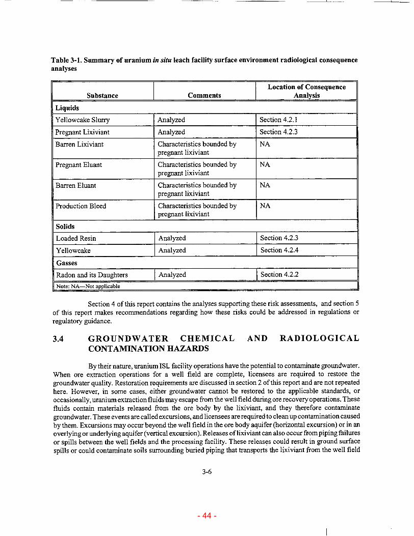
Table 3-1. Summary of uranium in situ leach facility surface environment radiological consequence analyses
Location of Consequence
Substance Comments Analysis
Liquids
Yellowcake Slurry Analyzed Section 4.2.1
Pregnant Lixiviant Analyzed Section 4.2.3
Barren Lixiviant Characteristics bounded by NA pregnant lixiviant
Pregnant Eluant Characteristics bounded by NA pregnant lixiviant
Barren Eluant Characteristics bounded by NA pregnant lixiviant
Production Bleed Characteristics bounded by NA pregnant lixiviant
Solids
Loaded Resin Analyzed Section 4.2.3
Yellowcake Analyzed Section 4.2.4
Gasses
Radon and its Daughters TAnalyzed Section 4.2.2
Note: NA-Not applicable
Section 4 of this report contains the analyses supporting these risk assessments, and section 5 of this report makes recommendations regarding how these risks could be addressed in regulations or regulatory guidance.
3.4 GROUNDWATER CHEMICAL AND RADIOLOGICAL CONTAMINATION HAZARDS
By their nature, uranium ISL facility operations have the potential to contaminate groundwater. When ore extraction operations for a well field are complete, licensees are required to restore the groundwater quality. Restoration requirements are discussed in section 2 of this report and are not repeated here. However, in some cases, either groundwater cannot be restored to the applicable standards, or occasionally, uranium extraction fluids may escape from the well field during ore recovery operations. These fluids contain materials released from the ore body by the lixiviant, and they therefore contaminate groundwater. These events are called excursions, and licensees are required to clean up contamination caused by them. Excursions may occur beyond the well field in the ore body aquifer (horizontal excursion) or in an overlying or underlying aquifer (vertical excursion). Releases of lixiviant can also occur from piping failures or spills between the well fields and the processing facility. These releases could result in ground surface spills or could contaminate soils surrounding buried piping that transports the lixiviant from the well field
3-6
- 44 -

to the processing facility. The contaminated water may pose a health hazard to people, livestock, or wildlife. Additionally, an important consideration is the probability that an excursion or buried piping rupture might occur and not be detected. As described in section 2, monitoring programs are typically implemented by license conditions to minimize the likelihood of undetected releases.
The risk assessment for lixiviant excursions or spills outside the processing facilities begins with a screening assessment of the frequency of occurrence. An examination of the reported events in the NRC Nuclear Material Events Database shows that these events are likely to happen during the lifetime of a uranium ISL facility.
Groundwater contamination presents regulatory concerns of a different nature from those associated with releases of radioactive materials in the surface environment. Whereas releases of radioactive materials may be acceptable so long as they are ALARA and do not cause unacceptable exposures, lixiviant excursions are not evaluated based on their level of concentration, volume, or area of contamination: any excursion is unacceptable. Therefore, since the record of reported events indicates that these events could be expected to occur during the lifetime of a uranium ISL facility, the likelihood of their detection and cleanup becomes a primary consideration.
Section 4 of this report contains the analyses of frequency of occurrence and the probability of detection for lixiviant excursions and for spills between the well fields and the processing facilities. Section 5 makes recommendations regarding how these events and their associated risks could be addressed in regulations or regulatory guidance. Where appropriate, potential mitigating actions to reduce risks are discussed.
3-7
- 45 -

4 CONSEQUENCE ANALYSES
4.1 CHEMICAL HAZARD CONSEQUENCE ANALYSES
As discussed in section 3 of this report, the hazardous chemicals in use at uranium ISL facilities were identified. Then, analyses were conducted to determine whether the typical quantities present at these facilities were sufficient to require the use of specific standard practices applicable to these chemicals. This section documents those analyses.
The following chemicals are typically used in substantial quantities at ISL facilities:
"* Anhydrous Ammonia (NH 3) "* Sulfuric Acid (H 2 SO4) "* Oxygen (02) "* Liquid Hydrogen Peroxide (50 percent) (H202) "* Sodium Hydroxide (50 percent) (NaOH) "• Barium Chloride (BaCl2) "• Carbon Dioxide (C0 2)
"* Hydrochloric Acid (30 percent) (HCI) "* Sodium Carbonate (saturated solution) (Na 2CO3) "* Sodium Chloride (saturated solution) (NaCl) "* Hydrogen Sulfide (H2S) "* Sodium Sulfide (Na 2S)
Use of these chemicals is controlled under a variety of regulations and agencies. To clarify the regulatory limits applicable to these chemicals, a summary of the key aspects of four relevant regulations follows.
40 CFR Part 68, Chemical Accident Prevention Provisions
This regulation includes a list of regulated toxic substances and threshold quantities for accidental release prevention.
29 CFR 1910.119, Occupational Safety and Health Administration Standards-Process Safety Management of Highly Hazardous Chemicals
This regulation provides a list of highly hazardous chemicals and toxic and reactive substances (chemicals that present the potential for a catastrophic event at or above the threshold quantity).
40 CFR Part 355, Emergency Planning and Notification
This regulation contains a list of extremely hazardous substances and their threshold planning quantities for the development and implementation of emergency response plans. There are about 360 extremely hazardous substances. Over a third ofthem are also Comprehensive Environmental Response, Compensation and Liability Act (CERCLA) hazardous substances. This regulation also lists reportable quantity (RQ) values for these substances for reporting releases. The RQs are for any CERCLA hazardous substances identified in table 302.4 of 40 CFR Part 302.
4-1
- 46 -

40 CFR 302.4, Designation, Reportable Quantities, and Notification-Designation of Hazardous Substances
This regulation provides a list of CERCLA hazardous substances. There are approximately 800 of these substances, and they are compiled from (i) the Clean Water Act, sections 311 and 307(a); (ii) the Clean Air Act, section 112; (iii) the Resource Conservation and Recovery Act, section 3001; and (iv) the Toxic Substance Control Act, section 7.
Only the key parameters and final calculation results have been presented in both international system and English units in this section.
Table 4-1 presents a summary of requirements from these regulations for the chemicals in use at uranium ISL facilities.
Table 4-1. Pertinent regulations for the chemicals used at uranium in situ leach facilities
Minimum Chemical Regulations Reporting
Ammonia (NH 3) Threshold Quantity (TQ) from Clean Air Act (CAA) for 40 CFR Part 68 Risk 4,536 kg [Approximately Management Planning (RMP) (10,000 lb) 40,823 kg TQ for Occupational Safety and Health Administration (OSHA) 29 CFR 4,536 kg (90,000 lb) are 1910.119 Process Safety Management (PSM) (10,000 lb) typically present Threshold Planning Quantities (TPQs) for 40 CFRPart355 Emergency Response 227 kg at ISL facilities] Plans (ERPs) (500 lb)
Reportable Quantity (RQ) for Comprehensive Environmental Response, 45.4 kg Compensation and Liability Act (CERCLA) from 40 CFR 302.4 (100 lb)
Sulfuric Acid TPQ for 40 CFR 355 ERP 454 kg (H2SO 4) (1,000 Ib) [Approximately 10,000 gal. (153,100 lb) are typically present at ISL facilities] Hydrogen TPQ for 40 CFR 355 ERP (concentration > 52%) 454 kg Peroxide (H202) (1,000 lb) [Approximately 7,000 gal. (70,000 lb) are TQ for OSHA 29 CFR 1910.119 PSM (concentration >52%) 3,402 kg
typically present (7,500 Ib) at ISL facilities]
Oxygen (02) Not Listed in any of the four regulations NA
Carbon Dioxide Not Listed in any of the four regulations NA (C0 2)
4-2
- 47 -

Table 4-1. Pertinent regulations for the chemicals used at uranium in situ leach facilities (cont'd)
Minimum Chemical Regulations Reporting
Sodium Not Listed in any of the four regulations NA Carbonate (Na 2CO) [Approximately 64,350 L (17,000 gal.) are typically present at ISL facilities]
Sodium Not Listed in any of the four regulations NA Chloride (NaCl) [Approximately 127,000 kg (140 tons) in two tanks are typically present at ISL facilities]
Barium Chloride Not Listed in any of the four regulations NA (BaCl2) (No specific typical quantities available)
Hydrochloric TQ from CAA for 40 CFR Part 68 RMP (concentration >37%) 6,804 kg Acid (HC1) (15,000 1)] [Approximately TQ from OSHA for 29 CFR 1910.119 PSM (for anhydrous HCI) 2,268 kg 10,000 gal. (5,000 lb) (95,850 lb) are typically present RQ for CERCLA from 40 CFR 302.4 2,268 kg
at ISL facilities] (5,000 lb)
Sodium RQ for CERCLA from 40 CFR 302.4 454 kg Hydroxide (1,000 Ib) (NaOH) [Typically 55-gal. drums (700 lb) are present at ISL facilities]
Hydrogen TQ from CAA for 40 CFR Part 68 RMP 4,536 kg Sulfide (H2S) (10,000 lb)
TQ from OSHA for 29 CFR 1910.119 PSM 680 kg (1,500 lb)
TPQ for 40 CFR Part 355 ERP 227 kg (500 lb)
RQ for CERCLA from 40 CFR 302.4 45.4 kg (100 Ib)
4-3
- 48 -

Table 4-1. Pertinent regulations for the chemicals used at uranium in situ leach facilities (cont'd)
Minimum Chemical Regulations Reporting
Sodium Sulfide Not Listed in any of the four regulations NA (Na2S)
INA-Not applicable
Examination of the MSDS sheets attached in appendix A and the analyses that follow demonstrate that these chemicals are typically present at uranium ISL facilities in sufficient quantity to pose a serious hazard if not properly handled. In addition, NH 3 and NaOH (strong bases), will react vigorously if they come into contact with the strong acids H2SO 4 and HC1 or with water. The oxidizers H20 2 and 02 will also react vigorously with natural gas which is piped to the ISL facility if a spark or ignition source is present.
4.1.1 Hazard Analysis for Ammonia
NH3 is the chemical agent most frequently involved in accidents reported under the EPA risk management program for high risk industries (Kleindorfer et al., 2000). NH13 is used at uranium ISL facilities for pH adjustment during the precipitation of uranium as an insoluble uranyl peroxide compound. NH 3 quantities and use rates vary among ISL facilities. However, they are within a small enough range that a sample calculation will suffice to demonstrate whether NH3 poses a significant hazard.
The NH 3 is commonly stored in a large-capacity tank located outdoors and is piped to the main plant for use in the processing circuit. Assuming a typical value for use rate of 549 standard liters per minute (slpm) [19.4 standard cubic feet per minute (scfm)] (at 0 'C and 14.7 lb per square inch absolute), which is equivalent to 25 kg/hr (55 lb/hr) as shown in the following calculation:
From the Ideal Gas Law, 1 gram mole of NH 3 occupies 22.4 liters (L) at 0 'C and 14.7 lbs per square inch absolute (psia).
Standard conversion factors for 22.4 L are 5.92 gal. and 0.791 ft3.
Therefore, using standard conversion factors, the header from the main storage tank has a flow rate of 19.4 ft/min. x 17 gm/gm mole x 1 gm mole/0.791 ft3 x 1 lb/454 gmn x 60 min./l hr =
55 lb/hr.
Therefore, a maximum leak rate of 25 kg/hr (55 lb/hr) could reasonably occur inside the facility.
The NH 3 in liquid form is not the primary hazard. Rather, the liquid rapidly evaporates to a hazardous gaseous state. The National Institute for Occupational Safety and Health (NIOSH) specifies that the concentration of NH 3 that is immediately dangerous to life and health (IDLH) is 300 parts per million (ppm) (National Institute of Safety and Health, 1997). Assuming that there would be pure NH 3 (i.e., 106 ppm) at the site of a piping rupture inside the ISL facilities, the NH3 released at a typical flow rate of 19.4 scfin would require a fresh air input of (19.4 scfm x 106 ppm /300 ppm) = 65,000 scfm at the location of the pipe break to adequately dilute the concentration to below the IDLH value of 300 ppm.
4-4
- 49 -

Since this is a substantial air flow in a localized area that could not be provided by a standard building ventilation system, an NH 3 header pipe break would constitute a significant hazard. In addition, the NH 3 will likely be released as a liquid spray under pressure and will also pose an additional hazard to the skin and eyes of any personnel in the immediate vicinity of the pipe break. Further, since plant personnel could be on an elevated catwalk at the time of the spill, there could be a delay in exiting the spill location. Additionally, NH 3 will react vigorously with water as well as with H 2SO4 and HCI, two strong acids used in ISL uranium extraction.
In summary, NH3 is the chemical most frequently involved in accidents reported under the EPA risk management program for high risk industries (Kleindorfer et al., 2000). A break in the NH 3 supply line at an ISL facility could result in the introduction of around 549 slpm (19.4 scfin) of NH3 and would require about 65,000 scfm of ventilation flow to dilute the concentration below the 1DLH value of 300 ppm. Therefore, NH 3 presents a significant toxicological hazard to facility workers. Workers incapacitated by such an accident would be unable to respond to an associated or concurrent radiological accident. Other hazards associated with NH 3 include a major leak in the outdoor storage tank and associated piping and accidental contact with process wastes, H2SO4, HCl, or water.
To minimize the probability and consequence of an NH3 accident, NH3 system design and operating procedures should be consistent with American National Standards Institute, Safety Requirements for the Storage and Handling of Anhydrous Ammonia (American National Standards Institute, 1989). Following are examples of recommendations that provide safe handling ofNH3 consistent with this pamphlet.
* Supply piping in the NH 3 system should be fitted with an excess flow valve that automatically closes if flow rate exceeds a specific value. The valve shall be located as close to the storage tank as possible.
"* All nonrefrigerated NH 3 piping should conform to the applicable sections of the American National Standards Institute/American Society of Material Evaluation standard code for pressure piping.
"• Positive pressure, self-contained, full face respirators should be readily available in the immediate vicinity of NH 3 piping and process operations.
Prudent design would also ensure that NH 3 piping is placed so as to minimize impact from vehicles or other objects that might cause ruptures. The CNWRA recommends that NRC guidance specify that uranium ISL facility operators follow design and operating practices published in accepted codes and standards that govern NH 3 systems such as those referenced in Safety Requirements for the Storage and Handling of Anhydrous Ammonia (American National Standards Institute, 1989).
4.1.2 Hazard Analysis for Sulfuric Acid
H2SO 4 is used at ISL facilities to split the uranyl carbonate complex from rich eluate into carbon dioxide gas and uranyl ions in preparation for their precipitation via the addition of H20 2. H2SO4 quantities and use rates vary among ISL facilities. However, they are assumed to be within a small enough range that a sample calculation for one plant will suffice to demonstrate whether H2SO4 poses a significant hazard.
4-5
- 50 -

The H2SO4 is stored in a tank located outdoors and is piped to a day tank (personal observation) in the main plant for use in the processing circuit. The day tank is much smaller, typically on the order of 1,703 L (450 gal.). The day tank is normally bermed for spill containment.
H2SO4 is extremely irritating, corrosive, and toxic to tissue, resulting in rapid destruction of the tissue and causing severe bums (Lewis, 1993).
From the MSDS (appendix A) for 93 percent H2SO4:
Threshold Limit Value (TLV) = 1 mg/m3
Short-Term Exposure Limit (STEL) = 3 mg/m3
The National Institute for Occupational Safety and Health (1997) lists an IDLH value of 15 mg/m3.
Using the conversion factor from American Conference of Governmental Industrial Hygienists
(1995):
TLV in 1 mg/m3 = (TLV in ppm) x (gram molecular weight of substance)/24.45
Given that the molecular weight of H2SO4 is 98 g/mole:
TLV for H 2 SO 4 = (1 mg/r 3) x 24.45/98 = 0.25 ppm
STEL for H 2SO 4 = (3 mg/m3) x 24.45/98 = 0.75 ppm
IDLH for H2S0 4 = (15 mg/m3) x 24.45/98 = 3.75 ppm
Given that the vapor pressure for H2SO4 is 0.0016 mm Hg at 40 'C (104 'F) (from MSDS, appendix A):
Equilibrium vapor concentration for H2SO 4 at 40 'C and atmospheric pressure =
0.0016 x 10⁶/760) = 2.1 ppm
TLV and STEL are limits which primarily pertain to the operational environment, and not to an accident situation. They represent conditions under which it is believed that nearly all workers may be repeatedly exposed without adverse effect. The TLV generally pertains to an 8-hr workday and a 40-hr work week, whereas the STEL generally pertains to a 15-min. exposure. In this context, although the equilibrium vapor concentration given above is greater than the TLV and STEL, it is expected that a spill of 93 percent H2SO4 in a typical uranium ISL facility would not pose a significant inhalation hazard to workers as long as there is normal air dilution available from the facility ventilation system. Should the H 2SO 4 spill occur when the ventilation system is inoperational, then persons would need to exit the facility quickly. Finally, the formation of mists and sprays, such as from a leak in the piping system, should be avoided, as these could cause harm through contact with the skin or through inhalation.
As an additional consideration, H2SO4 reacts vigorously with NH 3, Na2CO 3, NaOH, and water, all of which are present at uranium ISL facilities. Suitable precautions should therefore be taken to ensure that accidental contact with these chemicals is prevented. At some facilities, the H 2 SO 4 day tank is situated
4-6
- 51 -

close to other eluate processing tanks, such that a simultaneous leak in more than one tank system could
cause a vigorous reaction between the acid and the water in the eluate solutions.
The CNWRA recommends that NRC guidance specify that uranium ISL facility operators follow design and operating practices published in accepted codes and standards that govern H2SO 4 systems (see the MSDS in appendix A).
4.1.3 Hazard Analysis for Oxygen
Oxygen is normally added to the barren lixiviant upstream of the injection manifold. The 02
concentration in the lixiviant is typically maintained at around 500 mg/L (0.0312 lb/ft3). The 02 is delivered by truck and is stored on site under pressure in a tank in liquid form. The 02 is allowed to evaporate, and the gas is then transported via pipes and is introduced into the barren lixiviant piping. At some facilities, the 02 is fed into the barren lixiviant header via a common connection, whereas at other facilities it is fed via multiple connections to each individual injection well pipe. Sincej oints are susceptible to leaks, the common header system is inherently safer. Normally closed solenoids are sometimes used to automatically shut off the 02 supply in case of power failure. Most well header houses are also equipped with an exhaust ventilation system. The normally closed solenoids and the exhaust ventilation reduce the risk of 02 leaks in the lixiviant injection piping and buildup in the header house.
Because 02 readily supports combustion, fire and explosion are the main hazards associated with its storage and use. All materials that are flammable in air bum more vigorously in 02. Combustibles such
as oil and grease will bum with nearly explosive violence in 02 if ignited. Care must therefore be taken to
remove all oil, grease, and other combustible material from piping systems and containers before putting
them into 02 service. Cleaning methods used by manufacturers of 02 equipment are described in CGA G-4. 1,
Cleaning Equipment for Oxygen Service (Compressed Gas Association, Inc., 1996a) and in the Handbook
of Compressed Gases, in chapter 11 (Compressed Gas Association, Inc., 2000a). Sources of ignition should
be eliminated to the extent possible. Sudden opening of valves is to be avoided as this can result in ignition.
Safety measures, including providing system isolation and barriers, are discussed in ASTM G-88, Standard
Guide for Designing Systems for Oxygen Service (American Society for Testing of Materials, 1997). Piping
containing liquid 02 must be equipped with pressure relief devices that prevent the buildup of excessive pressure due to vaporization when liquid is trapped between valves in piping. A detailed discussion on the design and installation of gaseous 0, piping systems may be found in CGA G-4.4, Industrial Practices for
Gaseous Oxygen Transmission and Distribution Piping Systems (Compressed Gas Association, Inc., 1993a)
This publication includes requirements for both underground and above-ground piping, as well as material specifications, velocity restrictions, location and specifications for valves, and the design and specification of metering stations and filters.
02 is shipped as a gas, at pressures of 13,887 kPa (2,000 psig) or above, and also as a cryogenic liquid at pressures below 1,480 kPa (200 psig) and temperatures below -232 F° (- 147 C0 ). The 02 storage
facilities should be a safe distance away from other storage tanks and process facilities to effectively isolate them from fires and accidents in other portions of the process. Standards to ensure safety with 02 systems at user sites are detailed in National Fire Prevention Association publications such as NFPA-50, Standard for bulk Oxygen Systems at Consumer Sites (National Fire Prevention Association, 1996). At the temperature of liquid 02, ordinary carbon steels and most alloy steels lose their ductility and are considered unsuitable for use. Austenitic stainless steels such as Types 304 and 316, nickel-chrome alloys, nickel, Monel 400,
copper brasses, bronzes, and aluminum alloys are more suitable for use in liquid 02 service.
4-7
- 52 -

02 presents a substantial fire and explosion hazard. Accordingly, uranium ISL facility licensees should comply with accepted industry standards for handling this material. General precautions for safe handling of gaseous 02 are contained in CGA-4, Oxygen (Compressed Gas Association, Inc., 1996b). A thorough discussion of necessary precautions to be used for liquid 02 can be found in CGA P-12, Safe Handling of Cryogenic Liquids (Compressed Gas Association, Inc., 1993b) and in the Handbook of Compressed Gases, in chapter 2 (Compressed Gas Association, 2000a).
In view of the hazards presented by liquid 02, the CNWRA recommends that NRC guidance specify that uranium ISL facility operators follow design and operating practices published in accepted codes and standards that govern 02 systems.
4.1.4 Hazard Analysis for Hydrogen Peroxide
Hydrogen Peroxide (H20 2) is used in the precipitation phase of the uranium ISL process. A 50-percent solution of H202 is added to an acidified uranium-rich solution (-0.3 kg H20 2/kg U30 8) to form an insoluble uranyl peroxide compound, which is then typically fed to a thickener for further processing into yellowcake. The 50-percent H20 2 solution is normally stored in a tank of large capacity located outdoors and is piped to the main plant for use in the processing circuit.
H202 is a strong oxidizer, and is a reactive, easily decomposable compound. Its hazardous decomposition products include oxygen and hydrogen gas, heat, and steam. Conditions that can cause decomposition include mechanical shock, incompatible materials, light, ignition sources, excess heat, combustible materials, strong oxidants, rust, dust, and pH > 4.0. Incompatible materials include alkalies, oxidizable materials, finely divided metals (e.g., magnesium, iron), alcohols, and permanganates (see the MSDS in appendix A). Although many mixtures of H202 and organic materials do not explode upon contact, the resultant combinations can be detonable either upon catching fire or from impact. In addition, when sealed in strong containers, even a gradual decomposition of H202 to H20 + ½2 02 can cause excessive pressure to build up which may then cause the container to burst explosively (Lewis, 1993).
Solutions, vapors, and mists of H-202 are irritating to body tissue. The eyes are particularly sensitive to this material, and a 50-percent solution will cause blistering of the skin. Inhalation of the vapors can bum the respiratory tract.
From the MSDS in appendix A, for a 50-percent H20 2 solution:
NIOSH IDLH = 75 ppm 1 ppm = 1.4 mg/in3
Specific Gravity = 1.1
The OLI ESP 6.2e software program (OLI Systems, Inc., 1999) was used to calculate the vapor pressure of H20 2 solute over a 50-percent H202 solution. This yielded a vapor pressure = 0.65 mm Hg @ 30 °C.
Therefore, the concentration of H20 2 in air at saturation can be as high as (0.65/760 x 106) = 853 ppm (volume basis), which is well in excess of the IDLH concentration of 75 ppm.
In addition, as illustrated in the following example calculation, a leak in the H202 piping could result in a localized concentration inside the process building in excess of the IDLH value within minutes.
4-8
- 53 -

Typical values used for the H 2 0 2 flowrate; the volume of the process building; and the heating, ventilation, and air conditioning (HVAC) system capacity are as follows:
Flowrate of 50-percent H20 2 solution = 1.14 Lpm (0.3 gpm)
Volume of the process building = (170' x 100' x 20') W = 340,000 ft3 = (340,000 ft3 x 0.02831 m3/ft3) = 9,625 M3.The building HVAC system is designed for 5 air changes per hour.
In addition, if a 0.38 Lpm (0.1 gpm) leak goes undetected for 10 min.:
Volume of leak = (0.1 gpm x 3.7854 liters/gal. x 10) L = 3.7854 L.
Mass of leak = (3.7854 L x 1.1 kg/L) kg = (4.063 x 10⁶) mg.
Mass of H20 2 in leaked solution = (4.063 x 10⁶)/2 = (2.032 x 10⁶) mg.
In 10 min., the building HVAC system will have performed (5 x 10/60) air changes = 0.83 air changes.
Volume of the process building = 9,625 m3.
Volume of air in which the leaked H20 2 can volatilize = (1 + 0.83) x 9,625 m3 = 17,646 n3.
Concentration of H20 2 vapor in process building = (2.032 x 10⁶) mg/17,646 m3 = 115 mg/i 3.
IDLH for H20 2 vapor = 75 ppm = (75 x 1.4) mg/m3 = 105 mg/m3.
This example illustrates that an H20 2 piping system leak in the process building has the potential to result in localized vapor concentrations in excess of the IDLH value within minutes. Further, an H20 2 leak in a confined space such as a piping trench has the potential to generate lethal concentrations of vapor at an even faster rate. The CNWRA recommends that NRC guidance specify that uranium ISL facility operators follow design and operating practices published in accepted codes and standards that govern H20 2 systems (see the MSDS in appendix A).
4.1.5 Hazard Analysis for Sodium Hydroxide
Sodium hydroxide (NaOH) is used at uranium ISL facilities for pH control during radium removal from the barren lixiviant bleed stream using a conventional barium/radium sulfate co-precipitation process. NaOH quantities and use rates vary among ISL facilities. However, they are assumed to be within "a small enough range that a sample calculation for one plant will suffice to demonstrate whether NaOH poses "a significant hazard.
NaOH is typically stored as a 50-percent solution in 208-L (55-gal.) drums, and is pumped to the bleed neutralization and precipitation tanks at around 11.4 Lpm (3 gpm) using a variable frequency pump.
NaOH will react vigorously with HC1 and water, both of which are present at uranium ISL facilities. It is a cbrrosive irritant to the skin, eyes, and mucous membranes and can cause bums and deep ulceration. Mists, vapors, and dusts containing NaOH cause small bums, and contact with the eyes rapidly causes severe damage. NaOH ingestion causes serious damage to the mucous membranes or other tissues
4-9
- 54 -

contacted. Inhalation of the dust or mist can cause damage to the upper respiratory tract and to lung tissue (Lewis, 1993). The MSDS in appendix A provides further safety information on this chemical.
From the NIOSH Pocket Guide to Chemical Hazards (National Institute for Occupational Safety and Health, 1994):
NIOSH/Occupational Safety and Health Administration (OSHA) Exposure limits [time-weighted average (TWA)] = 2 mg/m3
NIOSH IDLH = 10 mg/m3
The OLI ESP 6.2e software program (OLI systems, Inc., 1999) calculated the vapor pressure over a 50-percent NaOH solution as 0 mm Hg @ 30 'C.
Therefore, NaOH is not volatile, and a spill of 50-percent NaOH solution in a uranium ISL facility will not pose a significant inhalation hazard to workers. The OSHA exposure limit and NIOSH IDLH apply to NaOH as an airborne contaminant such as a dust or mist. Dust is not a concern since uranium ISL facilities typically employ NaOH solutions and not dust-producing NaOH in solid form. However, mists and sprays from leaks in piping systems need to be avoided, as these could cause harm through contact with the skin or through inhalation.
Finally, NaOH reacts vigorously with HC1, H2SO, and water, all of which can be present at uranium ISL facilities. The CNWRA recommends that NRC guidance specify that uranium ISL facility operators follow design and operating practices published in accepted codes and standards that govern NaOH systems (see MSDS in appendix A).
4.1.6 Hazard Analysis for Barium Chloride
BaCl2 is used at ISL facilities to remove radium from the barren lixiviant bleed stream using a conventional barium/radium sulfate co-precipitation process, where barium and radium form an insoluble salt with sulfate in the processing solution. BaC12 quantities and use rates vary among ISL facilities. However, they are assumed to be within a small enough range that a sample calculation for one plant will suffice to demonstrate whether BaC12 poses a significant hazard.
Typically, a solution (20 percent assumed for this evaluation) of BaC12 is prepared from BaCl2 crystals in mix tanks and is pumped to the bleed neutralization and precipitation tanks at up to 500 ml/min using variable frequency pumps.
BaC12 is poisonous when ingested or taken in through subcutaneous, intravenous, or intraperitoneal routes. Inhalation absorption of BaC12 is 60 to 80 percent, and oral absorption is 10 to 30 percent (Lewis, 1993). The MSDS in appendix A provides further safety information on this chemical.
From the NIOSH Pocket Guide to Chemical Hazards (National Institute for Occupational Safety and Health, 1994):
NIOSH/OSHA Exposure limits (TWA) = 0.5 mg/m3 NIOSH IDLH = 50 mg/m3 (as Ba)
The OLI ESP 6.2e software (OLI Systems, Inc., 1999) calculated the vapor pressure of a 20-percent BaC12 solution as 0 mm Hg @ 25 'C.
4-10
- 55 -
Therefore, BaC12 is not volatile, and a spill of 20-percent BaCl2 solution in the ISL facility will not pose a significant inhalation hazard to workers. The OSHA exposure limit and NIOSH IDLH are for BaC12 as an airborne contaminant such as a dust or mist. The formation of mists and sprays from a leak in the piping system and the dust from BaCl2 crystals/powder therefore need to be avoided as they could pose an inhalation hazard.
The CNWRA recommends that NRC guidance specify that uranium ISL facility operators follow design and operating practices published in accepted codes and standards that govern BaC12 systems (see MSDS in appendix A).
4.1.7 Hazard Analysis for Carbon Dioxide
CO2 is added to the lixiviant at uranium ISL facilities either upstream or downstream of the ion exchange resin vessels. The CO2 concentration in the lixiviant is typically maintained at about 2,000 mg/L. The CO2 is delivered by truck and is stored on site under pressure in a tank in liquid form. The CO2 is allowed to evaporate and the gas is then transported by pipe to the process flow stream where it is introduced into the lixiviant piping at around 997.4 kPa (130 psig). At some facilities the lixiviant booster pumps are interlocked to stop if the pressure in the lixiviant circuit rises over or drops below a specified operating range. This prevents piping over pressurization or lixiviant spills in event of leaks. The CO2 injection may, in turn, be interlocked with the lixiviant booster pumps such CO 2 that injection is stopped if the pumps stop. These interlocks minimize the risk of a CO2 leak or buildup in the facility or in the lixiviant injection piping.
Leakage in a confined space is the main hazard associated with CO2, because it will displace 02
and could lead to asphyxiation. CO2 concentrations of 10 percent or more can produce unconsciousness or death. The American Conference ofGovernmental Industrial Hygienists (1995) recommended TWA for CO 2
is 5,000 ppm (9,000 mg/m3), and the STEL is 30,000 ppm (54,000 mg/m3) (the MSDS for CO2 is in appendix A). Since gaseous CO2 is one and one-half times heavier than air, it can accumulate in low or confined areas, and floor level positive ventilation systems are recommended to effectively exhaust it. In addition, appropriate warning signs should be posted outside those areas where high concentrations of CO2
gas may accumulate. When entering low or confined areas where high concentrations of CO 2 gas may be present, a self-contained breathing apparatus should be used. Facility ventilation fans are often located at roof level, making them relatively ineffective for removal of CO2 from the buildings. Fans may be relocated to a position closer to the floor in both satellite and central processing plants to remedy this situation (Rio Algom Mining Corp., 1999b).
CO2 is typically stored outdoors on site in insulated, mechanically refrigerated tanks. Storage temperatures are maintained in the range of -20 to 2 'F (-28.9 to -16.7 'C) with corresponding CO2 pressures of 200 psig to 300 psig (1,480 kPa to 2,070 kPa). Ambient temperatures below 0 *F (- 17.8 'C) for prolonged periods may cause the tank pressure to decrease and require the use of a pressure-building vaporizer. Insulated CO2 bulk storage systems must be designed to safely contain the required pressure and to meet applicable federal, state, and local regulations. Further information regarding the safe handling and use of CO2 can be found in the following publications of the Compressed Gas Association: Handbook of Compressed Gases (2000a); CGA-6, Carbon Dioxide (1997); CGA G-6.1, Standard for Low Pressure Carbon Dioxide Systems at Consumer Sites (1995); and CGA G-6.5, Standard for Small Stationary Low Pressure Carbon Dioxide Systems (1992).
4-11
- 56 -

The primary problems associated with CO2 piping are ruptures from elevated pressure or from the loss of piping ductility at low temperature. Rapid depressurization will cause the liquid to autorefrigerate. Temperatures can decrease to - 109.3 'F (-78.5 'C) when dry ice is formed. This can cause the piping to fall below the minimum design temperature. Similarly, bulk containers that have lost vapor pressure and have autorefrigerated may become colder than their minimum design temperature. Repressurization and a safe return to service will require special procedures as detailed in CGA GC-7, Guide to the Preparation of Precautionary Labeling and Marking of Compressed Gas Containers (Compressed Gas Association, 2000b). All liquid CO2 piping should be designed to compensate for shrinkage at low liquid temperatures. The discharge of CO2 to the atmosphere will cause a significant thrust force (inherent with the discharge of a high-pressure boiling liquid) that the piping must be designed to safely withstand. A pressure relief valve must be placed between positive shut-off points in the system to compensate for rapid pressure increase that may be caused by thermal expansion (1 lb of liquid CO2 will expand to approximately 8.5 ft3 of gas at atmospheric pressure). These relief valves should be set to discharge at a pressure not greater than the maximum allowable container pressure and are typically set for 450 psig (3,100 kPa). The rapid discharge of liquid CO 2 through a line that is not grounded can result in a buildup of static electricity which may be dangerous to operating personnel. Grounding CO2 pipes is therefore an important design consideration. Flexible hoses used with low pressure liquid CO 2 should have a minimum working pressure of 500 psig (3,450 kPa) and be designed for low temperature operation. Piping materials acceptable for insulated bulk liquid service include carbon steel (with forged steel fittings rated at 2,000 lb) and stainless steels. Cast iron, grade A-120 galvanized steel pipe, polyvinyl chloride pipes plastic, and malleable iron fittings are not recommended for insulated bulk service. CO 2 used in wet service will form carbonic acid. Systems handling aqueous CO2, such as the lixiviant piping, should be fabricated from CO 2 corrosion resistant materials.
In view of the potential for CO2 to displace oxygen and cause risk of asphyxiation, the CNWRA recommends that NRC guidance specify that uranium ISL facility operators follow design and operating practices published in accepted codes and standards that govern CO 2 systems.
4.1.8 Hazard Analysis for Hydrochloric Acid
Hydrochloric acid (HC1) is used at ISL facilities for pH control during radium removal from the barren lixiviant bleed stream via a conventional barium/radium sulfate co-precipitation process. HC1 quantities and use rates vary among ISL facilities. However, they are assumed to be within a small enough range that a sample calculation for one plant will suffice to demonstrate whether HC1 poses a significant hazard. As representative values, this analysis assumes that HC1 is stored as a 30-percent solution and is pumped to the bleed neutralization and precipitation tanks at up to 500 ml/min (0.13 gpm) using a variable frequency pump.
The HCI will react vigorously with NaOH, water, Na2CO 3, and H2SO 4 all of which can be present at uranium ISL facilities. It is a corrosive irritant to the skin, eyes, and mucous membranes. A concentration of 35 ppm causes irritation of the throat after short exposure (Lewis, 1993). The MSDS in appendix A, provides further safety information on HCl.
The following HC1 properties are from the NIOSH Pocket Guide to Chemical Hazards (National Institute for Occupational Safety and Health, 1994):
TWA = 5 ppm IDLH = 50 ppm
4-12
- 57 -

1 ppm = 1.52 3 mg/m3
Further, from Perry's Chemical Engineer's Handbook (Perry and Green, 1984):
Vapor Pressure of 30 percent HCl = 15.1 mm Hg @ 25 'C Density of 30 percent HCI = 1.1493 @ 20 'C
Therefore, the concentration of HCl in air at saturation (@ 25 °C and atmospheric pressure) can be as high as (15.1 x 10⁶/760) = 19,868 ppm, which is well in excess of the IDLH concentration of 50 ppm.
In addition, as shown below, a leak in the HC1 piping could result in a localized concentration inside the building close to the IDLH value in approximately 30 min.
The following typical values are assumed:
Flow rate of 30 percent HC1 to the process = 500 ml/min (0.13 gpm) Volume of the process building = (170 x 100 x 20) ft3 = 340,000 ft3 = (340,000 x 0.02831) m3
= 9,625 m3 Process building HVAC system is designed for 5 air changes per hour.
In addition, assuming a leak in the piping system of 150 ml/min (0.04 gpm) which goes
undetected for 30 min.,
Volume of leak = (0.15 x 30) L = 4.5 L (1.19 gal.)
Mass of leak = (4.5 L x 1.1493 kg/L) = 5.2 kg (5.2 x 10⁶) mg
Mass of HC1 in leaked solution = (5.2 x 106) x 0.3 = (1.6 x 10⁶) mg
In 30 min., the building HVAC system will have performed 2.5 air changes
Volume of the process building = 9,625 m3
Volume of air in which the leaked HCl can volatilize = (1 + 2.5) x 9,625 m3 = 33,687 m3
Concentration of HC1 vapor in process building = (1.6 x 10⁶) mg/33,687 m3 = 47 mg/m3
IDLH for HC1 vapor = 50 ppm = (50 x 1.52) mg/m3 = 76 mg/m3
This example illustrates that an HC1 piping system leak in a uranium ISL facility has the potential to result in localized vapor concentrations close to the IDLH value within approximately 30 min. Further, an HC1 leak in a confined space such as a piping trench has the potential to generate lethal concentrations of vapor at an even faster rate.
Therefore, a spill of 30 percent HC1 in a typical uranium ISL facility could pose a significant inhalation hazard to workers, especially if the HVAC system is inoperational. In such a case, any person entering or already present within the facility would have a very short time to exit before injury. The CNWRA recommends that the MSHA be made aware of this potential hazard.
4-13
- 58 -

Finally, HCl reacts vigorously with NaOH, water, Na2CO 3, and H2 SO4 , all of which can be present in ISL facilities. Precautions should therefore be taken to ensure that accidental contact of HC1 with NaOH or water is prevented.
The CNWRA recommends that NRC guidance specify that uranium ISL facility operators follow design and operating practices published in accepted codes and standards that govern HC1 systems (see the MSDS in appendix A).
4.1.9 Hazard Analysis for Sodium Carbonate and Sodium Chloride
Sodium carbonate (Na 2CO3) and NaC1 are used at ISL facilities for regeneration of the ion exchange resin. The loaded resin is typically contacted with a solution containing around 90 gm/L (0.75 lb/gal.) of NaCl and 20 gm/L (0.17 lb/gal.) of Na2CO3 (soda ash) in a sequence that regenerates the resin by removing the uranyl dicarbonate ions from the resin and converting them to uranyl tricarbonate. While the quantities and use rates for these chemicals vary among ISL facilities, they are assumed to be within a small enough range that a sample calculation will suffice to demonstrate whether these chemicals pose a significant hazard.
In one case, a 32-percent solution of Na2CO3 is prepared in a commercially available saturator by passing warm water [at around 122 F° (50 'C)] through a bed of soda ash. The saturated solution is stored in an indoor tank. A 26.4-percent-saturated solution of NaCl is similarly prepared using a commercially available brine generator, and is also stored in indoor tanks. Using a multi stage elution circuit, about 170,340 L (45,000 gal.) of eluate solution containing the NaCl and Na2 CO3 is used to contact approximately 14,160 L (500 ft3) of resin.
Both NaCI and Na2 CO 3 can be skin and eye irritants. Na2CO3 is also moderately toxic by inhalation. In addition, Na2CO 3 will react vigorously with H2SO 4 (Lewis, 1993) and with HC1, which can be present at uranium ISL facilities. The MSDS in appendix A, provides further safety information on these chemicals.
Since Na2CO 3 was reported to be moderately toxic by inhalation, the OLI ESP 6.2e software program (OLI Systems, Inc., 1999) was used to calculate the vapor pressure over a 32 percent Na 2CO 3 solution as 0 mm Hg @ 50 'C.
Therefore, Na2 CO3 is not volatile, and a spill of 32 percent Na2CO 3 solution in a uranium ISL facility will not pose a significant inhalation hazard to workers. Since several tons of Na2 CO 3 salt will be used as feed in the saturator, precautions should be taken to ensure that inhalation of the dust is avoided. The formation of a Na2CO 3 solution mist from a piping system leak should also be avoided as an inhalation hazard. Finally, precautions should be taken to prevent accidental contact of Na2 CO 3 salt or solution with HSO4 .
The CNWRA recommends that NRC guidance specify that uranium ISL facility operators follow design and operating practices published in accepted codes and standards that govern Na2CO3 and NaCI systems (see MSDS in appendix A).
4-14
- 59 -
4.1.10 Hazard Analysis for Hydrogen Sulfide and Sodium Sulfide
H2S is used to immobilize heavy metals during groundwater restoration.
The two main hazards associated with H2S are fire and leakage in a confined space. Because it is a flammable gas normally transported and stored in liquid form, the amount of flammable material is much greater per unit volume, making it a dangerous fire hazard when exposed to heat, flame, or oxidizers (Lewis, 1993). H2S is also a toxic, irritating, and asphyxiant gas. The American Conference of Governmental Industrial Hygienists TLV-TWA is 10 ppm (14 mg/m3), and the STEL is 15 ppm (21 mg/m3), while the OSHA ceiling concentration is 20 ppm [Handbook of Compressed Gases, (Compressed Gas association, 2000a)] and the NIOSH IDLH is 100 ppm [NIOSH Pocket Guide to Chemical Hazards (National Institute for Occupational Safety and Health, 1994)]. H2S is a poison and a severe irritant to the eyes and mucous membranes. The primary routes of entry for occupational use are inhalation and eye exposure. It has a strong odor of "rotten eggs" at concentrations as low as 0.1 ppm, changing to a sickening, sweet odor as levels rise above 50 to 200 ppm. However, exposure above 100 ppm will rapidly deaden the sense of smell, making it an insidious poison. The Handbook of Compressed Gases (Compressed Gas Association, 2000a) states that for maximum safety, indoor storage should be avoided and that indoor areas should have positive ventilation with at least six volumes of air change per hour. Since H2S is added to injection well headers, design of header houses should include adequate ventilation, and the instrumentation and control design should be checked for adequate provisions (safety interlocks) to prevent injection during abnormal or unsafe process conditions. In addition, adequate precautions are required to ensure personnel safety when entering a confined space such as a piping trench carrying an H2S line.
The location ofH2S storage sites should be a distance away from other storage tanks and process facilities such that they are effectively isolated from fire and accidents. In addition, uranium ISL facility design should ensure that storage sites for H2S are not near oxidizing materials or acids.
Detailed information on the precautions required for the safe handling of H2S and for the
procedures and equipment for its use may be found in CGA G-12, Hydrogen Sulfide (Compressed Gas Association, 1996) as well as in the Handbook of Compressed Gases (Compressed Gas Association, 2000a). The MSDS sheets for hydrogen sulfide has been included in appendix A.
Sodium sulfide (Na2S) may be used instead of 12S for the in-situ precipitation of orebody chemicals during groundwater restoration operations. Under certain conditions, sodium sulfide can react violently with water to liberate hydrogen sulfide and free alkali (Lewis, 1993). If Na2S is used, care is required to ensure that the reactions proceed in a controlled manner. The Na2S can be flammable, and contact with heat, flame, or other sources of ignition should be avoided. Materials to avoid include strong oxidizing agents, strong acids, and most common metals. Sodium sulfide (Na2S) is corrosive and will cause severe eye
and skin bums. Routes of entry into the body include inhalation, ingestion, and contact with the skin.
The CNWRA recommends that NRC guidance specify that uranium ISL facility operators follow design and operating practices published in accepted codes and standards that govern H2S and Na2S systems (see MSDS in appendix A).
4-15
- 60 -

fI~
4.1.11 General Consideration of Chemical Risk
The risks associated with using the standard chemical process industry approach to design and safety may not necessarily match the acceptable level of risk for radiological processes. Consequently, there may exist a much higher level of risk from chemical events than from radioactive events at uranium ISL facilities. This disparity in risk between chemical and radiological accidents may be acceptable as long as the design contains adequate safeguards to ensure that these two categories of accidents do not impact each other or that the consequences of the accidents are sufficiently small. Addressing the acceptability of this potential disparity in risk is beyond the scope of this report.
4.2 RADIOLOGICAL HAZARD CONSEQUENCE ANALYSIS
The radiological hazards assessment considers the characteristics of fluids at various places in a uranium ISL facility process stream, yellowcake, and gaseous effluents. For each substance, the initial step taken was to conservatively model the consequence for a release. If the consequence assessment demonstrates that an exposure limit might be exceeded, further assessment is performed or mitigating actions are considered.
In the subsections that follow, only the key parameters and final calculation results have been presented in both international system and English units.
4.2.1 Thickener Failure and Spill
Uranium processing facilities commonly use a thickener and a filter press to concentrate yellowcake slurry (figure 2-4). The thickener stores yellowcake slurry before it is transferred to the dryer. During normal operations, most of uranium progeny is removed and the slurry poses no substantial radiation hazard, because the primary source of radiation is alpha emissions that are attenuated by the liquid slurry. Calculations, included as appendix B, indicate that standing next to the thickener tank would result in an external dose rate of about 5 x 10⁻⁷ Sv/hr (0.05 mrem/hr). This translates into a working-year (2,000-hr) dose of about 1.2 x 10- Sv (120 mrem), well within exposure limits in 10 CFR Part 20.
A potential hazard exists if U3.0 is released into the air in a breathable form. A large source for such a hazard is the thickener. It is uncertain whether a spill from the thickener would be entirely contained within the processing building. The building is normally designed to contain spills (floors are sloped away from doorways and spilled liquids flow into sumps where they may be pumped to other storage tanks), but a major spill could overwhelm these design features. The processing buildings also contain berms for various other tanks. This scenario assumes that the spilled U30 8 slurry would occupy the portion of the level floor outside the individual tank berms, where 20 percent of the thickener volume escapes the building. A 1994 thickener accident at the Irigaray ISL facility resulted in about 20 percent of the thickener content being spilled inside and outside of the processing building (Cogema Mining, Inc., 1995).
A spill from the thickener could be caused by events such as a catastrophic tank failure (i.e., a break of a supporting leg or facility damage from a natural event) or break of the exit pipe and valve at the bottom of the thickener. For such events, the entire contents of the thickener could be released. For this scenario it is assumed that the thickener contains 278 m3 (73,500 gal.) of slurry and 24,200 kg (53,300 lb) U30. Assuming that 20 percent of the thickener volume exits the building, the exterior spill would contain 55.6 m 3 (14,700 gal.) of slurry and 4,835 kg (10,660 lb) of U30 8.Assuming that the 55.6 m3(4,700 gal.) that
4-16
- 61 -

spills from the process building covers a 1,000 m2 area, the 4,835 kg (10,660 lb) of U30 8 slurry will have an average depth of about 5.6 cm (2.2 in.) assuming no spill mitigation. Over time, the water in the slurry will evaporate or soak into the ground, leaving dry yellowcake powder over a wide area. Based on a U30, density of 8.30 g/cm3, the average depth of the dried U30 8 on the ground surface would be about 0.06 cm (0.024 in.) (Chemical Rubber Company, 1994). The potential for yellowcake powder to be inhaled is the sole substantial radiological hazard.
Of interest are the potential radiological health consequences from such a spill to onsite workers and offsite residents. These doses were determined for various time periods and distances from the spill. The time periods were for durations that the spill receives no mitigating action and is available for airborne transport. For these analyses, the release time does not begin until the yellowcake spill has dried and become available for airborne transport. The time periods were varied from 0.5 to 24 hr. Consequences were calculated for down wind distances from the spill that vary from 0 to 5,000 m (16,400 ft.).
Initially, while the U30, remains wet, it is expected to remain primarily at the spill location. However, once the spill area dries, it is assumed that wind will begin to carry the U30 8 down wind and eventually offsite. The drying time will depend primarily on the level of solar radiation, wind, vapor pressure, and surface infiltration; but it is anticipated that some of the surface U3O8 would dry quickly and become available for transport. These analyses assume that at some point all of the U30 would be available for transport. Under favorable soil conditions (high porosity, low compaction) and favorable climate conditions (high solar radiation, high wind speed, low vapor pressure) bulk water loss to soil and initial surface drying and removal ofU3O8 would be expected within the first hour. This scenario makes the unrealistic assumption that no efforts will be made to clean up the spill. The two primary factors affecting U30, removal would be time and wind speed. The longer the spill remains undisturbed and the higher the wind speed, the greater the amount of U30, that would be removed from the spill site and carried to receptors. The following empirical expression for fractional airborne release accounts for both time and wind speed (U.S. Nuclear Regulatory Commission, 1980)
f= 0.001 + 4.6 x 10⁻⁴(1- e--°1 5ut)u1"78 (4-1)
where
f - fractional airborne release u - wind speed (m/s) at 15.2 m (50 ft)elevation t - duration of the release (h)
The fractional airborne release will provide the total quantity ofIU3O8 released to the atmosphere during a given time period. This empirical expression was originally developed to describe accidents involving spills of plutonium oxide from falling drums. As was done in NUREG-0706 (U.S. Nuclear Regulatory Commission, 1980), it is assumed that this expression is valid for U308. The term "0.001" in Eq. (4-1) represents the initial release resulting from a falling container during a drum accident. This term has been removed for this analysis, since no material will be released until the water evaporates, yielding
f= 4.6x 10⁴(1- e-0 15 ut )u1 "78 (4-2)
To use Eq. (4-2), a value for wind speed at 15.2 m (50 ft) is required. Data from the National Climatic Data Center (NCDC) (2000) were used to determine an average wind speed for the four states
4-17
- 62 -

(Nebraska, New Mexico, Texas, and Wyoming) that contain uranium ISL extraction facilities. The wind speed information for each of the States is shown in table 4-2. The average wind speed over all sites within the four States was determined to be 4.7 m/s (10.5 mi/hr), as shown in the statistical summary of wind speed information in table 4-3.
The wind speeds reported by NCDC do not include measurement heights. However, wind speed measurements are typically made at 9.1-rn elevation (30-ft elevation), but may range up to several hundred feet. The height is usually selected to be above the surface boundary layer. The atmospheric surface boundary layer is typically about 9.1-rn high (30-ft high), but can be much greater due to varying surface irregularities such as buildings, forests, and vegetation. For these analyses, it was assumed that the NCDC wind speeds were measured at 9.1-rm elevation (30-ft elevation) and were converted to equivalent estimated 15.2-m (50-ft) measurements. The variation of wind speed with height can be described by the following power law expression (Linsley et al., 1982)
k
= Vii -- (4-3) ZI
where V - estimated wind speed at height z V, - measured wind speed at height z1 z - height for estimated wind speed zi - height for measured wind speed k - von Kirmn-n constant
When the value of the von Kkmdn constant is not known with certainty, it is recommended that it be set at 0.4. Assuming that all wind speeds reported by NCDC were taken at 9.1 m (30 ft), then the average wind speed of 4.7 m/s (10.5 mi/hr) would be estimated to be about 5.8 m/s (12.9 mi/hr) at 15.2 m (50 ft).
As an example, using Eq. (4-2) with an 8-hr release and a 5.8-rn/s (12.9 mi/hr) wind speed gives a fractional airborne release of about 1.1 x 10⁻², which for this scenario is a total release over the 8-hr period of 51 kg (112.5 lb) of U30 8. A back calculation yields a resuspension factor of 6.1 X 10⁻⁶ n-f, which is outside the range (9 x 10⁻⁸ to 5 x 10⁻⁷ m-m) reported in NUREG/CR-5512 (Kennedy and Strenge, 1992) for U30 8, but is conservative. For these analyses it was assumed that U30, release from the spill site was continuous and steady during the time period of interest. Additionally, it is assumed that the released fraction of uranium fills a volume 1 m (3.28 ft) above a square-shaped spill area and is removed continuously from the site at the wind speed of 1.9 rn/s (4.2 mi/hr) for a height of 1 m (3.28 ft) estimated using Eq. (4-3). The average U30 8 concentration above the spill site will be calculated by dividing the fraction of uranium activity released from the spill over a given time period by the total air volume passing over the spill site during that same time period. A state of equilibrium is assumed such that the amount of resuspended material over unit time equals the amount of material removed by the wind. This concept is depicted graphically in figure 4-1. In this way, the average U308 concentration in air above the spill is calculated using
Q (0.848)mf x (s/a)
Q= h-,Ku't(3,600)
4-18
- 63 -

Table 4-2. Wind speed information for various cities within Nebraska, New Mexico, Texas, and Wyoming from the National Climatic Data Center (2000)*
Average Annual Wind Average Annual Wind State City Speed (mifhr) Speed (m/s)
Nebraska Grand Island 11.8 5.3
Nebraska Lincoln 10.1 4.5
Nebraska Norfolk 11.2 5.0
Nebraska North Platte 10.1 4.5
Nebraska Omaha Eppley AP 10.5 4.7
Nebraska Omaha (North) 9.1 4.1
Nebraska Scottsbluff 10.6 4.7
Nebraska Valentine 9.7 4.3
New Mexico Albuquerque 8.9 4.0
New Mexico Clayton 12.0 5.4
New Mexico Roswell 8.7 3.9
Texas Abilene 11.9 5.3
Texas Amarillo 13.5 6.0
Texas Austin 9.1 4.1
Texas Brownsville 11.3 5.1
Texas Corpus Christi 12.0 5.4
Texas Dallas-Forth Worth 10.7 4.8
Texas Del Rio 9.7 4.3
Texas El Paso 8.8 3.9
Texas Galveston 11.0 4.9
Texas Houston 7.7 3.4
Texas Lubbock 12.4 5.5
Texas Midland-Odessa 11.1 5.0
Texas Port Arthur 9.6 4.3
Texas San Angelo 10.3 4.6
Texas San Antonio 9.1 4.1
Texas Victoria 9.9 4.4
Texas Waco 11.1 5.0
Texas Wichita Falls 11.6 5.2
Wyoming Casper 12.8 5.7
Wyoming Cheyenne 12.9 5.8
Wyoming Lander 6.8 3.0
Wyoming Sheridan 8.0 3.6
*National Climatic Data Center. Average wind-speed data from National Climatic Data Center website (http://www.ncdc.noaa-eov/ol/climate/online/ccd/avewind.html). Accessed August 11,• 2000.
4-19
- 64 -

Table 4-3. Statistical summary of wind speed information presented in table 4-2 for various cities within Nebraska, New Mexico, Texas, and Wyoming
Average Annual Standard Average Annual Standard
State Wind Speed (mi/hr) Deviation (mi/hr) Wind Speed (m/s) Deviation (m/s)
Nebraska 10.4 0.8 4.6 0.4
New Mexico 9.9 1.9 4.4 0.8
Texas 10.6 1.5 4.7 0.7
Wyoming 10.1 3.2 4.5 1.4
Nebraska, 10.4* 1.6* 4.7* 0.7* New Mexico, Texas, and Wyoming
*Average and standard deviation are for all available sites within the four States of interest.
Figure 4.1 Graphical representation of Eq. (4-4) showing how near-surface wind speed and spill area are used to determine the total volume of contaminated air removed from the spill site during a given time period. This air volume is used with the uranium release fraction to estimate the average uranium concentration in the air above the spill site.
4-20
wind volume per second
Im
spill area
z
1.9 m/s wind speed
X
%FX_
- 65 -

where
h - Assumed uniform-mixing height of airborne contamination (m) Q - U308 concentration in air above the spill site (pCi/m3) m - mass of U308 in spill (g) A - area of spill (m2) uI -- wind speed at I-m elevation (m/s) s/a - specific activity of uranium (pCi/g) 0.848 - converts mass of U30O to mass of U 3,600 - converts time t in hours to seconds
The specific activity of uranium is 6.77 x 10⁵ pCi/g as reported in 10 CFR Part 20, Appendix B.
For determination of down wind U30 8 concentrations, a Gaussian plume model of the following form was utilized (Faw and Shultis, 1993; Lamarsh, 1983)
C(x,y,z) = Q expK- Y-2- (z+h)2 + (yexp[ Y2 +(Zh)2 jj 2 u'CY o 7 _ 2 Cy2 2 2 ex 2 02 (4 -5)
where
C(x,y,z) - concentration at some position x,y,z from the spill (pCi/m3) x - down-wind distance from the spill on the ground surface (m) y - perpendicular distance from x on the ground surface (m) z - vertical distance from x (m) Q - concentration at spill (pCi/m3) a - fraction of concentration that reaches the ground that is reflected u' - wind speed at 1 m (m/s) Ca - Pasquill-Gifford diffusion parameter (in) h - stack release height (m)
The Gaussian model is acceptable without correction when the deposition velocity is less than 1 cm/s, since vertical turbulence dominates any tendency toward gravitational settling. Since U308 has a deposition velocity of approximately 1 cm/s, disregarding the effects of gravitational settling will add some conservativeness to the model (U.S. Nuclear Regulatory Commission, 1980). Additionally, the effects of radioactive decay may be disregarded, since the half-lives of 234U, 235U and 238U are all much greater than the modeling times of interest.
The original Pasquill-Gifford diffusion parameters were presented as plots (Gifford, 1968), but have since been updated by Miller (1984) to equation form, as
CY(x) = x(alln x + a2 ) and 1 (4-6)
cyz (x) = Iexp(bI + b2ln x + b31n2x)
2.15 where ai, bi are coefficients based on atmospheric stability category.
4-21
- 66 -

Using Eq. (4-6) requires the selection of an atmospheric stability category. Atmospheric stability classes range from A (extremely unstable conditions) to G (extremely stable conditions). The average surface wind speed at 1 m (3.28 ft) above ground for the four states containing uranium ISL facilities is 1.9 m/s (4.2 mi/hr). Depending on the level of daytime insolation and the level of cloudiness, the atmospheric stability could range from conditions A to B under these wind speeds. Condition B was selected as being more stable and thus more conservative, with less lateral mixing resulting in a higher concentration directly down wind. The coefficient values for atmospheric stability class B are a, (- 0.015), a2 (0.25), bi (- 0.99), b2
(0.82), and b3 (0.017) (Miller, 1984).
For the other parameters of Eq. (4-6), x was varied for distances ranging from 100 m to 5,000 m (328 to 16,400 ft) , y was set equal to zero to maximize the concentration (assuming the receptor is directly downwind), z was set equal to 1 m (3.28 ft) to give the concentration at the receptor height, and h was set equal to 1 m (3.28 ft) to simulate a near-surface release. The reflected fraction (a) was set to 1, since no realistic value could be found in the literature, and 1 is the most conservative choice.
The varied downwind concentrations were then converted to doses using inhalation dose conversion factors (DCFs) from Federal Guidance Report No. 11 (U.S. Environmental Protection Agency, 1988). This method was also used to calculate an on-site dose (x = 0 m) based on the uranium concentration estimated to be directly above the spill site. The following formula was used
D(x,y,z) = BIC(x,y,z)t; y = 0, z = Im (4-7) where
D(x,y,z) - inhalation dose (mrem) B - breathing rate (m3/yr) I - inhalation-to-DCF (mrem/pCi) C(x,y,z) - concentration at some position x,y,z from the spill (pCi/m3 ) t - duration of exposure (yr)
For these analyses, the breathing rate was assumed to be 1.05 x 10' m3/yr, a conservative value used for light outdoor activity (Bureau of Radiological Health, 1970; U.S. Nuclear Regulatory Commission, 1992). An inhalation-to-DCF of 1.254 x 10-' mrem/pCi was used for U308, calculated using an activity-weighted average of the 234U, 235U, and 23.U class Y dose conversion factors reported in Federal Guidance Report No. 11 (U.S. Environmental Protection Agency, 1988). U30 is reported to have a lung clearance class Y, which indicates that any material entering the deep respiratory tract will be retained on the order of years (U.S. Environmental Protection Agency, 1988). For most radionuclides, including 234U, 235U, and 238U, the class Y DCFs are also the most conservative, producing the highest dose estimates. The estimated downwind doses resulting from a U30 8 spill for varying distances and release durations are shown graphically in figure 4-2.
The calculations using the simple Gaussian plume model with many assumptions shows that, if no remedial or personnel protection actions were taken, offsite doses remained below 2.5 x 10-' Sv (25 mrem), and onsite doses could exceed 5 x 10'2 Sv (5 rem). If proper remedial action is taken, it is reasonable to assume that much smaller doses would be incurred by offsite receptors. Proper remedial action would contain and recover the spilled U30 8 before it was transported offsite by the wind. It is also reasonable to assume that cleanup personnel would be outfitted with protective equipment. Protection factors reported
4-22
- 67 -

L.OE+05 -
i.OE+04 5 rem occupational limit
1.OE+03
100 mrem public limit
L.OE+02 -.-.-.-.---------- ----------
---- 0
1 I.0E+01 - 100
o -- - 500
1.OE+00 -- 4- 1000
S5000
1.01E-01
1.0E-02 - -, - -- ) -- - - - - -- - -- - -- - -- -
1.0E-03
0 4 8 12 16 20 24
airborne release duration (h)
Figure 4-2. A plot of the downwind doses at various x-distances (meters) (y =0, z = 1 m) from a U30, spill, based on different airborne release durations (length of time that the U30, spill receives no mitigating action after drying to a point when airborne release is possible). These dose estimates assume that no remedial or personnel protection actions are implemented.
in 10 CFR Part 20, Appendix A for using particulate respirators range from 10 to 1,000. Use of a half facepiece, negative pressure respirator could reduce the expected dose by a factor of 10.
The distance to the offsite receptor was assumed to be 500 m (1,640 ft). This is reasonable, since a review of current uranium ISL facilities found the shortest distance between a processing facility and an urban development was 800 m (2,624 ft) forthe Crown Point, New Mexico, facility (U.S. Nuclear Regulatory Commission, 1997a). The Crown Point processing facility is adjacent to part of the southern fenceline, so it is possible that future urban development could be very near the facility. Although not a present concern, additional analyses may be required if urban development were to approach the 500-m (1,640 ft) boundary. Figure 4-2 shows that beyond a 4-hr airborne release duration the receptor dose remains nearly constant. To explain this phenomenon, figure 4-3 was plotted to show the opposing effects of average U308 concentration and release duration on dose at 0 m. As release duration increases, the average airborne U3O8 concentration decreases; resulting in a somewhat constant dose consequence beyond about 4 hr. The plot indicates that if mitigating action is required for a particular U30, spill, the response should be prior to spill dry out to be effective.
4-23
- 68 -
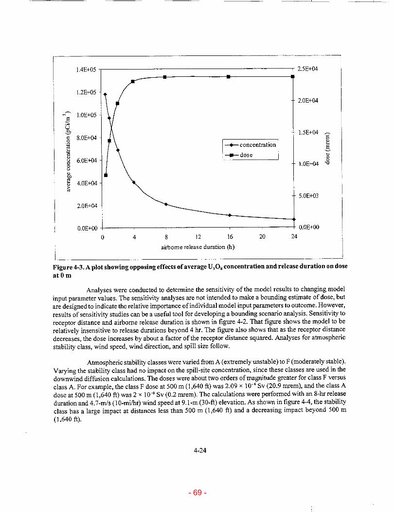
1 .4E±05
2.5E+04
1.2E+05 2.0E+04
S1.0E+05
o 1.5E+04 a 8.0E+04 -r s, concentrationE
--- dose S6.OE+04 " 1.0LE+04 " C
• 4.OE+04
5.OE+03
2.OE+04
0.OE+00 .. 0E+00
0 4 8 12 16 20 24
airborne release duration (h)
Figure 4-3. A plot showing opposing effects of average U3O8 concentration and release duration on dose at 0 m
Analyses were conducted to determine the sensitivity of the model results to changing model input parameter values. The sensitivity analyses are not intended to make a bounding estimate of dose, but are designed to indicate the relative importance of individual model input parameters to outcome. However, results of sensitivity studies can be a useful tool for developing a bounding scenario analysis. Sensitivity to receptor distance and airborne release duration is shown in figure 4-2. That figure shows the model to be relatively insensitive to release durations beyond 4 hr. The figure also shows that as the receptor distance decreases, the dose increases by about a factor of the receptor distance squared. Analyses for atmospheric stability class, wind speed, wind direction, and spill size follow.
Atmospheric stability classes were varied from A (extremely unstable) to F (moderately stable). Varying the stability class had no impact on the spill-site concentration, since these classes are used in the
downwind diffusion calculations. The doses were about two orders of magnitude greater for class F versus class A. For example, the class F dose at 500 m (1,640 ft) was 2.09 x 10⁻⁴ Sv (20.9 mrem), and the class A dose at 500 m (1,640 ft) was 2 x 10⁻⁶ Sv (0.2 mrem). The calculations were performed with an 8-hr release duration and 4.7-m/s (10-mi/hr) wind speed at 9.1-rn (30-ft) elevation. As shown in figure 4-4, the stability class has a large impact at distances less than 500 m (1,640 ft) and a decreasing impact beyond 500 m (1,640 ft).
4-24
2.5E+041.4E+05
- 69 -

Figure 4-4. A plot showing sensitivity of downwind dose to varying atmospheric stability classes for an 8-hr release duration
Wind speeds measured at 9.1-rm (30-ft) elevation were varied to measure the model sensitivity to wind speed. These wind speeds were converted to 0.3-rn (1-ft) and 15.2-m (50-ft) wind speeds. Within the four states that contain uranium ISL facilities, the highest monthly average wind speed is 7.2 m/s (16.2 mi/hr) for January at Casper, Wyoming. The lowest monthly average wind speed is 2.5 m/s (5.6 mi/hr) for October at Lander, Wyoming. For sensitivity analyses, wind speeds were varied from 1 m/s to 10 m/s. Stability class (B) and exposure duration (8 hr) were held constant. As shown in figure 4-5, varying the wind speed at 9.1 m (30 ft) elevation does not appear to have a significant affect on downwind dose, and the maximum downwind dose corresponds to a 9.1-rm (30-ft) elevation wind speed of approximately 1.7 m/s (3.8 mi/hr). This marginal impact is apparently due to the competing effects of an increasing source term (more U308 is removed with increasing wind speed) and a decreasing downwind concentration (the contaminant plume experiences greater diffusion with increasing wind speed). A different phenomenon occurs at the spill site, where the U308 concentration and resulting dose increase with increasing wind speed.
The model sensitivity to wind direction was measured by varying the location of the receptor away from the downwind direction. For sensitivity analyses, the receptor location was varied from 0 to 25 degrees away from the downwind direction. Wind speeds at 30-ft elevation (4.7 mI/s), stability class (B), and release duration (8 hr) were held constant. As shown in figure 4-6, varying the receptor location in relation to the wind direction appears to have a significant affect on downwind dose. As expected, the dose at the spill site is not affected by wind direction. The dose effect is dependent on the distance to the receptor,
4-25
300
200 A
-uB - C --- D
0 "---- E
100 - F
0 1
0 500 1000 1500 2000
distance to receptor (m)
- 70 -

20
15
- -2m/s
,•10 - a4 rn/sS
- 6--- 6 /s
-- 8 m/s -- - Om/s
0 0 500 1000 1500 2000
distance to receptor (in)
Figure 4-5. A plot showing sensitivity of downwind dose to varying 30-ft elevation wind speeds for an 8-hr release duration
but in general (for downwind distances less than 5,000 in), as the wind direction moves beyond about 15-20 degrees from the downwind direction the downwind dose decreases by about an order of magnitude.
Spill sizes were varied to measure the model sensitivity. The default spill size was 20 percent (4,835 kg U30 8 in 55.6 m3 of slurry) of the thickener volume, which is considered to be a reasonable upper bound. For sensitivity analyses, spill size was varied from 5 to 30 percent of the total thickener volume [278 m3 (73,000 gal.), 24,200 kg U30 8 (53,300 lbs U30 8)1. Stability class (B), release duration (8 hr), and wind speed 4.7 m/s (10.5 mi/hr) at 9.1-m (30-ft) elevation were held constant. As shown in figure 4-7, varying the spill mass [with associated spill areas adjusted to maintain a 5.6-cm (2.2-in.) depth] does not appear to have a significant effect on downwind dose. As expected, as the spill mass increases, the downwind dose also increases. However, the effect is minimal, since the downwind and spill site doses increase by a factor of about 2.5 when the spill mass is increased from 5 to 30 percent of the maximum thickener volume.
Based on these conservative calculations, it can be concluded that the dose from a spill to the public is expected to be below 10 CFR Part 20 limits. Doses to unprotected workers could exceed the 5 x 10⁻² Sv (5-rem) limit specified in 10 CFR Part 20. CNWRA recommends that the licenses have approved procedures for timely spill cleanup, protective equipment for workers involved in cleanup, and related worker training programs.
4-26
- 71 -

1.OOE+02
Figure 4-6. A plot showing sensitivity of downwind dose to varying wind directions for a 30-ft elevation wind speed of 4.7 m/s, stability class of B, and 8-hr release duration
4.2.2 Radon Release Consequence Analysis
A potential hazard exists if 2Rn is released into the air, especially in an enclosed area without adequate ventilation. A source for such a hazard is the ion-exchange columns used in the main and satellite ISL processing facilities. A pipe or valve failure at the ion-exchange column would be sufficient to release the pregnant lixiviant from the column, assumed to contain 2.1 x 10⁴ L (5,600 gal.). The pregnant lixiviant arriving from the well fields contains an elevated level of 222Rn, which in some groundwaters has been measured at levels greater than 3.7 x 10' Bq/L (10' pCi/L), as shown in table 4-4. For this analysis, a 22Rn
concentration of 3 x 10⁴ Bq/L (8.0 x 101 pCi/L) is assumed, which approximates the highest value reported inside a uranium recovery facility (see table 4-5). A spill from the ion-exchange column could be caused by an industrial accident such as a truck inadvertently backing into and breaking a pipe or valve.
This analysis assumes that an ion-exchange column is damaged such that pregnant lixiviant and resin drain into the processing facility at atmospheric pressure. It is further assumed that all of the "2Rn contained in the pregnant lixiviant is released instantaneously into the facility. This is a conservative assumption, because the solubility limit of radon in liquid phase at atmospheric pressure was estimated using the ESP software (OLI Systems Inc., 1999) to be 8.59 x 10' mol/L (2.94 x 10¹⁶ pCi/L), which is well above the assumed radon concentration of 8.0 x 10' pCi/L (3.0 x 10 Bq/L). The 222Rn is assumed to be released due to uncertain effects of aeration and mixing during the initial release of pregnant lixiviant from the ion-
4-27
1.OOE+01
1.OOE+00 E
" L 1.OOE-01
1.OOE-02
L.OOE-03
- 0 deg.
- 5 deg.
- 10 deg. 0-x--- 15 deg.
----- 20 deg.
-9-- 25 deg.
50000 1000 2000 3000 4000
distance to receptor (m)
- 72 -

Figure 4-7. A plot showing sensitivity of downwind dose to varying spill sizes for a stability class B, 8-hr release duration, and 30-ft elevation wind speed of 4.7 m/s. The percentages shown are 5 to 30 percent of the maximum thickener volume.
exchange column and during recirculation from the building sumps through the failed ion-exchange column. Uniform mixing was assumed in a room size of 6,500 m3 (2.3 x 101 ft3), which is the approximate size of a typical processing building. This assumption may be nonconservative, because radon is heavier than air and may not disperse uniformly.
Of interest are the potential radiological health consequences from such a spill to onsite workers and offsite residents. For this analysis, a dose was determined for an onsite male worker who performs 30 min of light activity in the immediate area of the accident. Doses were calculated using methodology provided by the National Council on Radiation Protection and Measurements (NCRP) (National Council on Radiation Protection and Measurements, 1984). Dose may be calculated as
D = 100. DCF- EEC. t (4-8) where
D - dose (tirem) 100 - conversion factor (100 rnrem = 1 mSv)
4-28
1.OE+02
1.OE+01
"'1.OE0- percent
-1-- 10 percent
o15 percent -*---1-- 20 percent
---- 25 percent
1.0E-02 -- 3 30 percent
1.OE-03
0 1000 2000 3000 4000 5000
distance to receptor (m)
- 73 -

Table 4-4. Example reported 2..Rn groundwater concentrations
222Rn Concentration Source
Bq/L pCi/L
8.77 x 10'-2.93 x 10' 2.37 x 10'-7.93 x 10' Kearney, W.F. Letter (August 2) to P. Mackin, Cente for Nuclear Waste Regulatory Analyses, Glenrock, WY: Power Resources, Inc. 2000.
4.92 x 10' 1.33 x 101 pCiIL Hydro Systems, Inc. Final Environmental Impact Statement to Construct and Operate the Crown Point Uranium Solution MiningProject, Crown Point, New Mexico. NUREG-1508. Washington, DC: U.S. Nuclear Regulatory Commission. 1997a.
4.81 x 10' 1.30 x 10' Hydro Systems, Inc. Final Environmental Impact Statement to Construct and Operate the Crown Point Uranium Solution Mining Project, Crown Point, New Mexico. NUREG-1508. Washington, DC: U.S. Nuclear Regulatory Commission. 1997a.
5.18 x 10⁴-7.14 x 10' 1.40 x 10⁶-1.93 x 10⁷ Krishnaswami, S., W. Graustein, and K. Turekian. Radium, thorium, and radioactive lead isotopes in groundwaters: Application to the in situ determination of absorption-Desorption rate constants and retardation factors. Water Resources Research 18(16): 1,633-1,675. 1982.
Table 4-5. Assumed activities used for pregnant lixiviant and loaded resin spill scenarios
Radionuclide Assumed Activity in Pregnant Lixiviant
Bq/L pCi/L 222Rn 3.0 x I0W 8.00 x 10⁵ 22 6Ra 1.3 x 10² 3.40 x10'
natural U 6.3 x 10³ (9.6 x 106)* 1.70 x 105 (2.60 x108)* 218 Po 1.3 x 10² 3.40 x10' 214Pb 1.3 x 10² 3.40 x10' 214Bi 1.3 x 10² 3.40 x10³
2 14po 1.3 x 10² 3.40 xl03
*Value in parentheses is for loaded resin (U.S. Nuclear Regulatory Commission, 1997b)
4-29
- 74 -

DCF - dose per unit equilibrium-equivalent activity concentration (mSv per Bq yr m-3)
EEC - equilibrium-equivalent concentration (Bq/m3) t - time (yr)
This NCRP dosimetry model provides an estimate for lung dose based on exposure to 122Rn. For a male performing light activity, the NCRP model assumes a breathing rate of 18.75 L/min and a DCF of 1.2 mSv y-'/Bq m-3. The EEC is an adjusted activity concentration for 222Rn that accounts for daughter disequilibrium and is calculated by Faw and Shultis (1993)
EEC = CO (4-9) F
where
CO - 222Rn concentration (Bq/m3) F - equilibrium factor
An equilibrium factor of F = 0.5 is conservative and is recommended for indoor spaces when data are unavailable (U.S. Environmental Protection Agency, 1986). The NCRP model assumes a quality factor of 20, which is appropriate for alpha particles. A volume of 2.1 x 10⁴ L (5,600 gal.) of pregnant lixiviant that has a .2.Rn concentration of 3 x 10⁴ Bq/L (8.0 x 10' pCiiL) could release up to 6.3 x 10' Bq (1.7 x 10l1 pCi) of 222Rn. If distributed uniformly in a 6,500 m3 (2.3 x 10' ft)facility, this would result in a 222 Rn concentration in the facility of 9.7 x 10⁴ Bq/m3. Using F = 0.5 and the assumed 222Rpn concentration (9.7 x 10⁴ Bq/m3) in Eq. (4-9) results in an EEC of 1.9 x 10' Bq/m3. In turn, if these values are used in Eq. (4-8), a 30-min dose of 1.3 x 10⁻² Sv (1.3 rem) is estimated for a male performing light activity without respiratory protection.
The analysis demonstrates that radon release is likely to happen during the lifetime of uranium ISL facilities. A simple NCRP model was used to estimate dose to a worker present in the area of the 222Rn
release for 30 min. The model is limited in this application, but is sufficient to demonstrate that a potential hazard exists. It remains uncertain whether using the internal volume of the facility of 6,500 m3 (2.3 x 101 ft3) for the 22Rn dilution volume is appropriate. Since the density of 22Rn is greater than that of air, the R22Rn concentration in the area of the accident and at lower elevations may be higher than the concentration calculated in this analysis. However, the conclusion would remain the same.
Based on the form of Eq. (4-8), any change to the 222Rn concentration or exposure time will have a linear affect on dose. For example, if the room size is doubled or the exposure time is halved, then the dose will be halved. Use of ventilation or atmosphere-supplying respirators designed to protect against gases should be sufficient to mitigate such consequences. Unprotected personnel should evacuate spill areas near ion-exchange columns or other areas that have pregnant lixiviant feeds and report any spills immediately. In addition to the normal monitoring requirements of 10 CFR Part 20, it is recommended that ISL facilities maintain proper equipment, training, and procedures to respond to large lixiviant spills or ion-exchange column failure. External dose consequences from pregnant lixiviant and loaded resin are evaluated in section 4.2.3 of this report.
4-30
- 75 -

4.2.3 External Consequence from Pregnant Lixiviant and Loaded Resin Spills
In section 4.2.2, this report discussed the potential consequences resulting from inhalation of 222 R released from pregnant lixiviant. This section evaluates the external radiation dose consequences from
pregnant lixiviant and loaded resin spills. Two scenarios are examined.
In the first scenario, pregnant lixiviant spills from an ion-exchange column and ponds to varying depths. The radionuclide activities are assumed as shown in table 4-5, with the additional assumption that 222Rn progeny are in equilibrium. To simplify the calculation, the lixiviant pond is assumed to be of infinite
area with 1 cm (0.4 in.), 5 cm (2 in.), 15 cm (6 in.), and infinite depths. Dose calculations were performed using DCFs for soil from Federal Guidance Report No. 12 (U.S. Environmental Protection Agency, 1993). Details for these calculations are shown in appendix C. For the most conservative calculation (infinite depth), the external dose rate estimate is about 2.7 x 10- Sv/yr (27 mrem/yr). Since this spill is likely to be cleaned up within hours, the external exposure to any one person is expected to be low and well within regulatory limits. The hourly exposure rate is about 3 x 10⁻⁸ Sv/hr (3.0 x 10⁻³ mrem/hr) (regulatory limit is 2 mrem/hr) and a worker on-site for a 24-hr period would receive an external dose of about 7.3 x 10⁻⁷ Sv (7.3 x 10⁻² mrem), which is far below the annual occupational exposure limit of 5,000 mrem. Consequently, conservatively modeled pregnant lixiviant spills have no significant external radiological consequence.
In the second scenario, pregnant lixiviant and loaded resin spill from an ion-exchange column to varying depths. The radionuclide activity concentrations are assumed as shown in table 4-5, using the natural uranium concentration for loaded resin. To simplify the calculation, the lixiviant and resin pond is assumed to be of infinite area with 1 cm (o.4 in.), 5 cm (2 in.), 15 cm (6 in.), and infinite depths. Dose calculations are performed using DCFs for soil from Federal Guidance Report No. 12 (U.S. Environmental Protection Agency, 1993). Details for these calculations are shown in appendix C. For the most conservative calculation (infinite depth), the external dose rate estimate is about 2.7 x 10⁸ Sv/yr (2.7 x 10⁻³ mrem/yr). About 99 percent of the total dose results from the resin-borne uranium. Since this spill is likely to be cleaned up within hours, the external exposure to any one person is expected to be low and well within regulatory limits. The hourly external dose rate is about 3 x 10⁻⁶ Sv/hr (0.3 mrem/hr) (regulatory limit is 2 mrem/hr from external sources in an unrestricted area) and a worker onsite for a 24-hr period would receive an external dose of about 7.4 x 10⁻⁵ Sv (7.4 torem), which is far below the annual occupational exposure limit of 5,000 mrem. Consequently, conservatively modeled pregnant lixiviant and resin spills have no significant external radiological consequence.
4.2.4 Yellowcake Dryer Hazard Analysis
Yellowcake dryers are used to dry the wet yellowcake into a powder. Two main types of dryers are used. Older and retrofit facilities generally use multiple hearth dryers, while newer facilities use rotary vacuum dryers. Since multiple hearth dryers operate at much higher temperatures [typically around 538 'C (1,000 'F)], and may be direct gas-fired, they are assumed to be more hazardous than rotary vacuum dryers.
Resources were not available to conduct a detailed hazard assessment of yellowcake dryers and their many components and failure modes. Therefore, four scenarios based on previously documented assessments in NUREG-0706 (U.S. Nuclear Regulatory Commission, 1980) were examined to determine hazards associated with the dryers.
4-31
- 76 -

Scenario 1: Fire and explosion in the yellowcake drying area
This assessment assumes that the uranium ISL facility has two yellowcake dryers, each having a capacity of about 1,950 kg (4,300 1b) of yellowcake, and two yellowcake dryer feed hoppers, each with a 4.4 m3 (155 ft3) volume. These volumes were found to be representative based on site visits and examination of system flow diagrams.
The total yellowcake inventory in the two dryers is 3,900 kg (8,600 lb). The average weight of a 55-gal. drum of yellowcake is 431 kg (950 lb) (Ferdinand, 2000). Therefore, the yellowcake inventory in two dryers is equivalent to about 9 drums.
The feed hoppers will each hold 4.4 m3 (155 ft3) of wet yellowcake from the filter press. With a specific gravity of wet yellowcake equal to 1.346, the total weight of wet yellowcake in the feed hoppers is (155 x 2) ft3 x (1.346 x 62.4) lb/ft3 or 26,037 lb.
Assuming that the material in the feed hoppers is 40 weight percent yellowcake (Ferdinand, 2000), the weight of yellowcake powder contained in the wet yellowcake is (.40 x 26,037 lb) or 10,415 lb. Assuming that a fire dries all the wet yellowcake in both feed hoppers, the yellowcake available for dispersion is (10,415/950) drums, or about 11 drums.
Therefore, the maximum yellowcake inventory that could be released in a fire or explosion scenario would be (9 + 11) drums, or 20 drums.
A more realistic estimate, used for the remainder of this analysis, is that some of the wet yellowcake is not converted into aerosol size particles by the fire or explosion. Therefore, about 10 drums of yellowcake could become airborne in the fire or explosion scenario.
Analyses in NUREG-0706 (U.S. Nuclear Regulatory Commission, 1980, p. 7-3) demonstrate that the consequences of yellowcake dryer explosions will be limited by the concentration of heavy material that can be maintained in the air. This is estimated to be approximately 100 mg/m3 (6.25 x 10⁻⁶ lbs/ft3 ) of airborne yellowcake material.
NUREG-0706 (U.S. Nuclear Regulatory Commission, 1980) also estimates an offsite dose of about 6.5 x 10' Sv (65 torem) to a 500-m 1,640-ft) location resulting from a yellowcake dryer explosion and eventual U30 release. This is the result of a release of 1.0 kg (2.2 lb) of U30 8 , assuming no filtration and that all insoluble particles are in the respirable size range. The radiation dose to the public resulting from off-normal yellowcake dryer events meets the 1 x 10⁻³ Sv (100 mrem/yr) public dose limit for normal operations in 10 CFR Part 20 but could exceed the 1 X 10⁻³ Sv (10 mrem/yr) constraint on air emissions of radioactive material to the environment in 10 CFR 20.1101, which represents a reportable event under 10 CFR 20.2203.
Based on experimental results, 100 mg/m3 (6.2 x 10⁻⁶ lb/ft3) is a reasonable assumption for an upper-bound, sustainable airborne U30O concentration (Selby et al., 1973). Selby et al. (1973) also reports that it is reasonable to assume that all materials will be released to the available airspace during an explosion, but will drop to 100 mg/m 3 (6.2 x 10⁻⁶ lb/ft3) concentration within a few minutes as the heavier materials are removed from suspension.
4-32
- 77 -

For the yellowcake dryer fire or explosion scenario, it is assumed that the airborne U30 8
concentration will drop to 100 mg/m3 (6.2 x 10⁻⁶ lb/f 3) within 10 min. The initial airborne U30 8 concentration is calculated by assuming that 4,300 kg (9,500 lb) (10 drums) of U308 will fill a room space of 3.5 x 10³ m3 (1.2 x 10' ft) (U.S. Nuclear Regulatory Commission, 1980). This results in an initial airborne U30 8 concentration of 1.23 x 10⁶ mg/m3 (7.7 x 10² lb/ft3) and an average concentration during the first 10 min, assuming steady reduction to 100 mg/m3, of 6.15 x 10' mg/r 3 (3.8 x 10⁻² lb/I). Since the dose effect is assumed to be linear with concentration, this average concentration may be used to calculate the dose expected during the first 10 min following the accident. Using Eq. (4-7) of section 4.2.1 of this report, and the relevant parameter values, gives a dose during the first 10 min of about 8.8 x 10⁻² Sv (8.8 x 10³ rem). This dose results from inhaling about 1.23 x 10² g U30 8, or about 59 cm 3 U30 8 , based on an assumed bulk density of about 950 lb U30 8 per 55-gal. drum. Additionally, this intake of about 1.04 x 10² g (0.23 lb) U far exceeds the 10 CFR 20.1201 (e) toxicity limit of 10 mg/wk for intake of soluble uranium.
The hazardous chemical risk from a yellowcake dryer fire or explosion is also substantial, since NIOSH reports the IDLH for amorphous silica (dust) to be 3,000 mg/m 3 (1.9 x 10⁻⁴ lb/ft3) (National Institute for Occupational Safety and Health, 2000) and the U.S. Department of Energy (DOE) reports the temporary emergency exposure limit (TEEL) TEEL-3 for amorphous silica to be 500 mg/mr3 (3.13 x 10' lb/ft3) (U.S. Department of Energy, 2001). The TEEL-3 level is that concentration below which nearly all individuals could be exposed without experiencing or developing life-threatening health effects. The average U30 8 airborne concentration (6.15 x 10' mg/m3) expected during the first 10 min following the accident far exceeds the critical levels for dust reported by NIOSH and DOE. Exposure to such an accident should be considered serious, and provisions should be made to evacuate and protect personnel. The inhalation dose for 10 min after the airborne U 308 concentration reduces to 100 mg/m3 is about 1.4 x 10⁻² Sv (1.3 rem).
Protection factors reported in 10 CFR Part 20, Appendix A for use of particulate respirators range from 10 to 1,000. Use of even a full-face piece, powered air-purifying respirator could reduce the expected dose by a factor of 1,000, but would still result in a dose of about 8.8 x 10² Sv (8.8 rem) during the ten minutes following the explosion and about 1.4 x 10-' Sv (1.4 mrem) during the second 10 min following the explosion. Each of these 10-min doses would be reduced by a factor of about 0.38 if the victim were unconscious, since the breathing rate would be reduced from 1.05 x 10⁴ m3/yrto about 3.94 x 10i m3/yr (Bureau of Radiological Health, 1970). The analyses indicate that yellowcake dryer fire or explosion scenarios could lead to doses that exceed the 5 rem/yr occupational dose limit of 10 CFR Part 20.
Limited data are available on the probability of a yellowcake dryer explosion. NUREG-0706 (U.S. Nuclear Regulatory Commission, 1980) reports an upper-limit failure rate of 5 x 10⁻³ per plant year. This frequency appears to be for a gas-fired multiple hearth dryer and is derived from failure rates observed for piping used in the transmission of natural gas. It is based on the conservative estimate of 52,000 m (170,000 ft) of piping per plant and does not take into account the probability of ignition given a failure. The failure rate for the rotary vacuum dryer is likely to be less, since it is not a gas-fired unit and uses hot oil as the heating medium for drying the yellowcake.
Because of the potentially severe consequences of a yellowcake dryer explosion, the checking and logging requirements contained in 10 CFR Part 40, Appendix A, Criterion 8 should be retained since no yellowcake dryer explosions have occurred since these criteria have been in effect. Operators should also develop and train crews on an emergency plan for such accidents, and should follow manufacturers recommendations for maintenance and operation of the dryers. Use of respirators is also recommended in the area of the yellowcake dryer when it is operating. Any proposed modifications to these requirements should be documented and justified in the license applications.
4-33
- 78 -

Scenario 2: Discharge Valve at Bottom of Dryer Fails Open, Overfilling a Drum and Spilling Dryer Contents
This scenario involves a maximum of 1,950 kg (4,300 lb) of yellowcake and lacks sufficient energy to aerosolize the yellowcake. Based on experiments, it is estimated that 0.1 percent ofU30 8 contained in a falling drum would become airborne (U.S. Nuclear Regulatory Commission, 1980). Ifthe same fractional release is considered valid for scenario 2, then the airborne release of U308 would be about a factor of 2,000 less than that for scenario 1. Deterministically, the consequence analyses for scenario 1 will bound scenario 2.
Scenario 3: Failure of Offgas Treatment System on one Dryer (Failure of Offgas Filter and Scrubber)
The offgas treatment system for a rotary vacuum dryer typically employs a baghouse filter and a scrubber. Due to its much higher operating temperature, a multiple hearth dryer relies exclusively on a scrubber for offgas treatment.
On most rotary vacuum dryers, the offgas treatment system is monitored for proper vacuum pressures using a vacuum sensor at the inlet throat of the dryer. Therefore, failure of the filter or the scrubber should be quickly detected.
The U308 emission rate from a typical dryer is estimated to be 1,400 g/hr (3.1 lb/hr) NUREG-0706 (U.S. Nuclear Regulatory Commission, 1980, p. 7-2). Therefore, a break in the offgas treatment system could result in the hot offgases being released in the dryer room at around 1,400 g/hr (3.1 lb/hr).
For uranium ISL facilities, where system parameters for the yellowcake emission control equipment are checked and logged hourly as required by Criterion 8 of 10 CFR Part 40, Appendix A, a scenario involving a break in the offgas system could be undetected for 1 hr, if automatic monitoring devices are not employed.
At a release rate of 1,400 g/hr (3.1 lb/hr), the maximum U30 8 airborne concentration in 1 hr would be 400 mg/m3 (2.5 x 10-' lb/ft), using the same room volume previously assumed in scenario 1. This amount of U30 8 would exceed the maximum sustainable concentration of 100 mg/m3 (6.2 x 10⁻⁶ lb/ft) assumed for scenario 1. Since no explosion is involved in this case, and the heavier U308 particles are expected to be removed from suspension within a few minutes, it is assumed that this scenario would result in a sustained airborne U30 8 concentration of 100 mg/M3 (6.2 x 10⁻⁶ lb/ft3). As reported for scenario 1, the unprotected dose rate for this case would be about 9 x 10⁻² Sv (9 rem/hr). This would be the case even if the release went undetected for longer than 1 h, due to the maximum sustainable concentration of U30. Based on the room size of 3.5 x 10³ m3 (12.4 x 10' ft3), it is reasonable to assume that 1,000 in2 (10,800 ft')is available to receive U30 8 deposition, including equipment surfaces. If only 100 mg/m3 (6.2 x 10⁻⁶ lb/ft3) can be maintained in suspension, then 1,050 g U308 would be deposited during the first hour following the break. This results in a U308 surface concentration of about 1.05 g/m 2, which is equivalent to about 0.89 g U/m2
(0.089 mg U/cm2). This is far below the natural uranium surface concentration of 2 mg/cm 2
(2.8 x 10-' lb/in.2 ) that is readily visible and therefore, U308 surface contamination could go undetected (U.S. Nuclear Regulatory Commission, 1983). However, the 100 mg/m3 (6.2 x 10⁻⁶ lb/ft3) airborne concentration for U30, should be visible, since it would appear to be about 80 times as dusty as construction traffic on an unpaved road [4.0 x 10-' mg/m3 (2.5 x 10⁻⁸ lb/ft3)], accounting for particle density differences of U303 and soil of 8.30 g/cm3 and 2.65 g/cm 3, respectively (Yu et al., 1993; Chemical Rubber Company,
4-34
- 79 -

1994; Pierzynski et al., 1994). Therefore, existing requirements in 10 CFR Part 40, Appendix A, Criterion 8 are appropriate and should be retained, since no yellowcake dryer explosions have occurred since these criteria have been in effect.
Scenario 4: Tornado Strikes to the Dryer Room
This scenario and its consequences are described in section 4.6 of this report. Scenario 1 bounds this scenario.
4.3 GROUNDWATER CONTAMINATION HAZARD CONSEQUENCE ANALYSIS
The use of ISL methods is not unique to uranium extraction. In certain copper-bearing ore bodies, for example, H2SO4 is sometimes injected to dissolve and extract copper minerals. By comparison, the additives typically used for uranium ISL in the United States are relatively benign. Nearly all currently operating uranium ISL extraction facilities in the United States use 02 as the primary oxidant (Mudd, 1998), and CO2 is often used to adjust the pH of lixiviant to desired levels (e.g., Power Resources, Inc., 1995). Changes to groundwater quality at uranium ISL extraction facilities result not so much from the addition of 02 and CO2 as from the mobilization of metals and trace elements that exist in the ore body. As noted previously, common radioactive constituents that may be mobilized by uranium ISL extraction solutions include uranium, thorium, radium, radon, and their respective daughter products. Nonradioactive trace elements can include arsenic, vanadium, zinc, selenium, and molybdenum (Kasper et al., 1979).
4.3.1 Groundwater Protection Regulations for In Situ Leach Facilities
For uranium ISL extraction facilities, injection wells are classified as Class mI wells (40 CFR 144.6), for which construction, operation, and monitoring requirements are specified in 40 CFR Part 146, Subpart D. Prior to injection of lixiviant, a UIC permit must be obtained (40 CFR 144.7). For aquifers that meet the definition of an underground source of drinking water (USDW) (40 CFR 144.3), UIC regulations allow for designation of ore bodies as exempted aquifers. To obtain an exempted aquifer designation for a uranium ore body, a extraction facility operator must present data that demonstrate the aquifer is expected to be both mineral producing and amenable to ISL extraction methods (40 CFR 144.7). Exempted aquifers have clearly defined boundaries, and the migration of lixiviant into nonexempted zones (excursion) must be controlled. Monitoring requirements must be specified in all UIC permits (40 CFR 144.54), and a plan must be submitted describing steps necessary to prevent movement of fluid into USDWs. Operators of Class III wells must also submit information on the expected overall effect of the project on the hydraulic gradient in potentially affected USDWs (40 CFR 144.54).
The NRC has regulated groundwater contamination and cleanup at ISL facilities under the authority of the Atomic Energy Act of 1954, as amended. The regulatory requirements cited in the preceding paragraph derive from the Safe Drinking Water Act and give EPA, or EPA-authorized States authority to regulate groundwater at ISL facilities under the EPA UIC program. NRC- and EPA-authorized regulatory programs are essentially duplicative in many aspects. The Commission has directed that the staff work with EPA to implement agreements by which NRC can defer to EPA regulation under its UIC program (U.S. Nuclear Regulatory Commission, 2000b).
4-35
- 80 -

4.3.2 Implementation of Groundwater Protection Requirements: Excursion Control Monitoring
At uranium ISL facilities, groundwater protection during operations requires the installation and monitoring of wells to detect potential horizontal and vertical excursions. A horizontal excursion is a lateral movement of ISL fluids outside the exempted portion of the ore-body aquifer. A vertical excursion is a movement of ISL fluids into overlying or underlying aquifers. Because construction and subsequent monitoring of excursion detection wells are expensive, operators desire to minimize the number of monitoring wells without compromising protection of nonexempted USDWs. Table 4-6 presents several examples of monitoring well location and spacing specifications that have been accepted by the NRC and incorporated into specific license conditions.
A typical horizontal excursion monitoring system, shown schematically in figure 2-3, consists of a ring of monitor wells completed in the same aquifer as the injection and production wells. The potential for horizontal excursions is controlled by maintaining well field production flow at a rate slightly greater than injection flow. This excess production is referred to as process bleed. When process bleed is properly distributed among the many production-injection patterns, the well field is said to be balanced. To minimize waste disposal costs, process bleed is limited to the minimum amount necessary to prevent excursions beyond
the well field boundary-typically, about I to 3 percent of the total production flow rate. Because operators strive to minimize process bleed, and because injection and production well flow rates tend to vary over time, maintaining a balanced well field requires continual monitoring and adjustment of flow rates.
Horizontal excursions are somewhat common at uranium ISL facilities. For example, between the years 1988 and 1995 in the Powder River Basin, Wyoming, twelve horizontal excursions were detected at the Highland Uranium Project (Power Resources, Inc., 1995); four were detected at the Irigaray Project, and five at the Christensen Ranch Project (Cogema Mining, Inc., 1995). Experience at other uranium ISL facilities was similar. Thus, from a probability-of-occurrence perspective, it is expected that one or more horizontal excursions will occur over the life of a typical uranium ISL facility. This may not be problematic, however, because the selected indicator parameters and UCLs allow detection early enough that corrective action can be taken before water quality outside the exempted aquifer boundary is significantly degraded. Significant risk from a horizontal excursion would occur only if it persisted for a long period without being detected.
Vertical excursion monitoring systems for both overlying and underlying aquifers typically consist of a set of wells that is located within the well field boundary in a seemingly random fashion with a density generally ranging from one per 3 acres to one per 5 acres (see table 4-6). Because of the relatively sparse density of vertical excursion monitor wells, a localized vertical excursion stands an increased chance of escaping detection. When vertical excursions are detected, they cannot always be retrieved by adjustment to the production-inj ection balance, because the overlying and underlying aquifers are hydraulically isolated from the production zone.
Common causes of vertical excursions include improperly cemented well casings, well casing failures, and improperly abandoned exploration wells (e.g., Cogema Mining, Inc., 1995, section 7.2.3.2). Vertical excursions can also occur where confining layers are leaky or discontinuous. Where confining layers are shown to be very thick and of negligible permeability, requirements for vertical excursion monitoring can be relaxed or eliminated (e.g., see table 4-6). Generally, vertical excursion monitoring requirements are
4-36
- 81 -

Table 4-6. Typical scales for single production-injection patterns and spacings between horizontal and vertical excursion monitor wells
Typical Production Horizontal Excursion Vertical Excursion Location Pattern Diameter Monitor Wells Monitor Wells
Crowe Butte Uranium 12.2-30.5 m 122-183 m (400-600 1 per 5 acres in Project, Nebraska' (40-100 ft) ft) apart, 91.4 m overlying aquifer only
(300 ft) from well field edge
Highland Uranium 30.5-42.7 m 122-244 m (400-800 1 per 3 acres, not more Project, Wyoming2 (100-140 ft) ft) apart, 76-183 m than 1,000 ft apart, in
(250-600 ft) from well both overlying and field edge underlying aquifers
Smith Ranch Project, 22.9-45.7 m Maximum 152 m I per 4 acres, not more Wyoming' (75-150 ft) (500 ft) apart, than 1,000 ft apart, in
approximately 152 m both overlying and (500 ft) from well field underlying aquifers edge
Crown Point Uranium -30.5 m Approximately 122 m 1 per 5 acres in Project, New Mexico4 (-100 ft) (400 ft) apart, overlying aquifer; 1 per
approximately 122 m 8 acres in any aquifers (400 ft) from well field above the first edge overlying aquifer
Christensen Ranch 15.2-30.5 m Downgradient: 91.4 m 1 per 3.5 acres in both Project, Wyoming5 (50-100 ft) (300 ft) apart, 91.4 m overlying and
(300 ft) from well field underlying aquifers edge; upgradient and sides: 152 m (500 ft) apart, 500 ft from well field
'Crowe Butte Resources, Inc. Applicationfor Renewal of USNRC Radioactive Source Material License SUA-1534. Denver, CO: Crowe Butte Resources, Inc. 1995. 2Power Resources, Inc. Operations Plan for Highland Uranium Project. Glenrock, WY: Power Resources, Inc. 1995. 3Rio Algom Mining Corp. Smith Ranch Facility Source Material License Application. Oklahoma City, OK: Rio Algom Mining Corp. 1999a. 4U.S. Nuclear Regulatory Commission. Final Environmental Impact Statement to Construct and Operate the Crown Point Uranium Solution Mining Project, Crown Point, New Mexico. NUREG-1508. Washington, DC: U.S. Nuclear Regulatory Commission. 1997a. 5 Cogema Mining, Inc. SupplementDataforRenewal SourceMaterialLicenseSUA-1431, Irigary and Christensen Ranch Project. Mills, WY: Cogema Mining, Inc. 1995.
4-37
- 82 -

only eliminated for underlying aquifers. For overlying aquifers, potential pathways for vertical excursions will always exist via production and injection boreholes that penetrate overlying confining layers to reach the ore body.
In conjunction with the installation of horizontal and vertical excursion monitoring systems, chemical constituents are selected to serve as excursion indicator parameters. Criteria for selection of an indicator parameter are that the constituent is found in elevated concentrations in uranium ISL process water and is generally nonsorbing and nonreactive so that it will be an early indicator of migrating lixiviant. UCLs are then established to determine when an indicator is present in concentrations statistically greater than background levels. Additional monitoring system details and analyses of risks associated with horizontal and vertical excursions are discussed in the following sections.
4.3.3 Excursion Risk Analysis
The consequence of an undetected excursion depends largely on site-specific hydrogeology, water quality, and water use. For this report, we assume initially that the consequence of an undetected excursion is an unacceptable degradation of a potential groundwater supply and that the risk of an undetected horizontal excursion cannot be ignored or screened out based on low consequence. That is, an undetected excursion would violate water quality standards (e.g., 40 CFR 264.92; or 10 CFR Part 40, Appendix A). Additionally, NRC must ensure that radiation exposure limits in 10 CFR Part 20 are not violated and that environmental protection regulations under 10 CFR Part 51 are complied with. Accordingly, the following risk analysis is focused on the probability that an excursion could result in an unacceptable degradation of an existing or potential groundwater supply. It is worth noting that, although the detection of horizontal and vertical excursions is frequent enough to be of concern, there were no reports of extraction fluid excursions being detected in off-site water supplies in any of the documentation for U.S. uranium ISL sites reviewed for this report. Therefore, for purposes of the following analyses of excursion risks, it is assumed that available technology and the resources set aside by surety arrangements would be sufficient for remediation of potential horizontal or vertical excursions before they could cause contamination of off-site water supplies. It is further assumed that current regulatory monitoring requirements are sufficient to preclude systematic or persistent human errors (e.g., failure to follow approved monitoring procedures) that might result in off-site excursions of uranium ISL fluids.
The probability that a horizontal or vertical excursion will degrade a water supply, p(d), can be estimated from the product of the probabilities from a chain of three sequential events
p(d) = p(l) p(2) p(3) (4-10)
where
p() - probability that an excursion will occur during the operational life of a well field
p(2) - probability that the excursion will migrate undetected past monitor-wells p(3) - probability that the undetected excursion will reach a water supply before
natural attenuation processes (e.g., sorption, dispersion) can reduce contaminant levels to near-background levels
4-38
- 83 -

As previously discussed, horizontal and vertical excursions are detected often enough at ISL facilities that one or more can be expected over the operational life of a well field. Accordingly, the value of p(l) is conservatively assumed equal to one for both horizontal and vertical excursions.
The value of p(3) depends largely on site-specific factors such as the groundwater flow rate and direction, geochemical conditions, proximity of water supply wells to the ISL facility, and plans for future water resource development. Actions taken by uranium ISL operators to minimize the value of p(3) can include periodic monitoring of nearby water supply wells. An innovative approach to eliminate the possibility of contaminating water supply wells may be implemented at the Crown Point Uranium Project in New Mexico, where operators agreed to install new municipal water supply wells farther away from the proposed ISL extraction area, if necessary.
An estimate ofp(2) can be obtained by making some general assumptions about excursion source zones and dispersion processes. To begin, consider the monitoring system illustrated in figure 4-8, which schematically illustrates detected and undetected horizontal excursions. It can be seen that the probability of an undetected excursion is greatest when (i) the source zone is small, at a fixed location, and persistent; (ii) there is little lateral spreading between the source zone and the monitor well positions; and (iii) the monitor wells are spaced far apart. The same principles apply to vertical excursions. These three factors must therefore be considered to assess the likelihood of an undetected excursion and are discussed in more detail in the following subsections.
0 00
S
* KONITORING WELL
0
0
00
0
Figure 4-8. Schematic illustration of a horizontal excursion monitoring ring showing a scenario where an excursion is detected (lower) and another where an excursion goes undetected (upper) (after Kasper et al., 1979)
4-39
- 84 -

4.3.3.1 Source Zone Size, Location, and Persistence
Horizontal excursion source zones typically develop when process bleed is not properly distributed throughout the well field. An excursion emanating from such a source zone would likely cover an area of several injection-production patterns and would be too wide to pass undetected through the horizontal excursion monitor wells. A greater probability of an undetected horizontal excursion occurs when an excursion source is small, localized, and near the edge of a well field. A pump failure at a production well could create such a source, but it would likely be detected quickly and repaired before an excursion could occur. A faulty pressure gauge or flow meter, however, could create a localized over-injection that might escape detection. If localized over-injection (or under-production) occurs in the middle of a well field, and the offending inj ection-production pattern is surrounded by other patterns, then the over-production is more likely to be absorbed and compensated for by the surrounding production-injection patterns, and an excursion would likely not occur. A localized production-injection imbalance that occurs on the edge of a well field would be affected by mixing between the adjacent well patterns. Consider, for example, a well field populated with five- or seven-spot patterns similar to those shown schematically in figure 2-3. If overinjection occurs in a single pattern at the edge of the well field, the over-injected fluid would be drawn laterally toward the neighboring production-injection patterns. If the excess production (process bleed) from the neighboring patterns is insufficient to take up the amount of over-injected fluid, one can qualitatively envision that this would result in a source zone for a potential excursion with a width along the well field edge that spans the width of the pattern where over-injection occurs plus a portion of the neighboring patterns. It is thus qualitatively assumed for the following analyses that an excursion resulting from overinjection near the edge of a well field would have an approximate minimum width of two-production injection patterns-on the order of 60 m (200 ft) for typical production injection patterns listed in table 4-6.
The size of a vertical excursion source zone also depends on the cause. Vertical excursions resulting from supposed confining layers that turn out to be discontinuous or leaky would cover a relatively large area. Conversely, source zones associated with injection well casing failures or improperly abandoned boreholes would be small, localized, and stationary. A vertical excursion source zone caused by a well casing failure might be only a few meters in width. Also, unless the casing failure is severe enough to cause a noticeable pressure drop, such an excursion source could persist until the next routine well integrity test, which is typically required only once every 5 yr. Assuming some advective spreading of contaminants in the event of a well casing failure, it is estimated that the minimum width of a vertical excursion source zone is on the order of about 10 m (30 ft).
4.3.3.2 Lateral Spreading between Source Zone and Monitor Wells
The concept of dispersion length [e.g., Schwarzenbach et al., 1993, Eq. (9-20)] is useful for assessing the degree of lateral spreading that would likely be associated with a migrating plume ofISL fluids. For Gaussian (i.e., random-process) dispersion of a point source contaminant, 95 percent of the contaminant can be expected to reside within about two dispersion lengths of the longitudinal axis of the plume. If excursion indicator parameter concentrations in ISL extraction water are substantially above background levels, concentrations above background should be readily detectable within about two dispersion lengths. Assuming a dispersion process that varies linearly with groundwater velocity [e.g., Gelhar et al. (1992), Eq. (2)] the dispersion length can be calculated from Eq. (4-11)
(T =- 2iHX (4-11)
4-40
- 85 -

where a - dispersion length (L) CH - horizontal transverse dispersivity (L) x - transport distance (L)
It can be seen that the dispersion length increases in proportion to the square-root of distance, x, which is the distance from the edge of the well field to the ring of monitor wells. The value of aH can be estimated from values reported in the literature. A survey of horizontal transverse dispersivity estimates by Gelhar et al. (1992) shows that horizontal transverse dispersivity values in a variety of aquifer types range from about 0.03-8 m (0.1-25 ft) for the scale of interest, with a median value of about 1 in (3 ft).
For a horizontal excursion, lateral dispersion is likely to be enhanced considerably by the dynamic hydraulic gradient that results from continual adjustment of injection and production flows. It is thus reasonable to consider that the appropriate dispersivity value for this situation might be near the upper end of observed values, but the median value of 1 m (3 ift) is conservatively used for this analysis. Using values of 120 in (400 ft) and 1 m (3 ft) for x and aH, respectively, yields a dispersion length estimate of about 15 m (50 ft). Counting two 15-m (50-ft) diffusion lengths to either side of a point contaminant source, it is estimated that about 60 in (200 ift) of lateral spreading would occur between a well field and a monitor well ring 120 m (400 ft) down gradient from the source. This lateral spreading would be in addition to the original width of the contaminant source zone. As previously discussed, a source zone would have an approximate minimum of about 60 m (200 ift). This yields an estimated width of about 120 m (400 ift) for a plume reaching a ring of monitor wells about 120 mn (400 ft) away.
In the event of a vertical excursion, lateral dispersion would not be enhanced by dynamic flow patterns as is expected in the ore-body aquifer. Hence, a significantly lower horizontal transverse dispersivity estimate of 0.1 in (0.33 ft) is used to calculate the dispersion length. Also, the transport distance to the nearest monitor well is variable for a vertical excursion, as the excursion could occur anywhere within the well field boundary, and vertical excursion monitoring wells appear to be placed somewhat randomly. For purpose of analysis, the case of a 150-m (- 500-ft) transport distance is examined, which yields a diffusion length of about 6 in (20 ft). Assuming a 10-m (30 ft) wide source zone and lateral spread of four diffusion lengths yields an estimated width of only about 34 m (110 ft) for a vertical excursion contaminant plume after a 150-m (-500-ft) transport distance.
A more robust estimate of excursion plume width can be obtained if indicator parameter concentrations are known for lixiviant and for baseline (preextraction) aquifer water. This can be accomplished using one of several available analytical solutions to delineate where indicator parameter concentrations in an excursion plume will exceed UCLs. The steady-state analytical solution of Liej et al. (1991) to the advection/dispersion equation for transport is convenient for this analysis, as it allows for a finite-width, constant-concentration source zone. The amount of lateral spreading can then be obtained by finding the value ofy that satisfies the following analytical solution:
CcL-Ck i~rc y-a ,(y+a'•
CU- Cbk - erfcl I -erfci, - (4-12) CO -Cbk 21 [ , ,r4ctx
4-41
- 86 -

where
y orthogonal distance from longitudinal axis of an excursion to the point were indicator parameter concentrations are equal to the UCL
a - half-width of the excursion source zone CUCL - UCL concentration of an indicator parameter Cbk - background concentration of an indicator parameter Co - extraction fluid concentration of an indicator parameter erfc - complimentary error function
As a check on the concept of counting dispersion lengths to estimate excursion plume width, an analysis using Eq. (4-12) was performed using data for the chloride indicator parameter reported for the Christensen Ranch ISL facility in the Powder River Basin, Wyoming. COGEMA Mining, Inc. (1995) reported postextraction chloride concentrations of 1,700 mg/L following the Christensen Ranch Willow Creek Research and Development test and a background concentration of 7 mg/L. The UCL for chloride at new Christensen Ranch well fields is 15 mg/L above background, which yields a value of 0.009 for the left side of Eq.(4-13).
For a horizontal excursion, the value ofy that satisfies Eq. (4-12) is about 70 m (230 ft), again assuming values of 1 m (3 ft) for a1H, a source zone width of 60 m (200 ft), and a transport distance (x) of 120 m (400 ft). The estimated excursion plume width is twice the value of y, about 140 m (460 ft). To compare this estimate to the previous example, note that the value of 0.009 for the left side of Eq. (4-13) represents a plume boundary that contains 99.1 percent of the contaminant mass. For a Gaussian dispersion process, this corresponds to three dispersion lengths to either side of the source zone. Using the dispersionlength method and assumptions of the previous example, yields a plume width of 150 m (490 ft). From this comparison, one can infer that the easier dispersion length method can provide a reasonable estimate of minimum excursion plume width when indicator parameter concentrations in extraction fluids are much greater than both UCL and background levels.
For a vertical excursion, using the previously assumed 150-m (500-ft) transport distance and 0.1 in for alt, the value of y calculated from Eq. (4-12) is about 23 m (75 ft). This yields a plume width of 46 in (150 ft) for the Christensen Ranch chloride data. Again, this is slightly more than the value estimated using the simpler dispersion length method.
The preceding analyses use a median value as an estimate of horizontal dispersivity and assume that macro-scale horizontal dispersion can be treated as a Gaussian process. This assumption is brought into question by research showing that transverse dispersivity changes with scale and therefore is not a truly Gaussian process. Rather, dispersion is affected by the variance and correlation scale of the hydraulic conductivity field. Dagan (1984), for example, derived closed form analytical expressions for apparent longitudinal and transverse dispersivity in heterogenous systems. He showed that the apparent transverse dispersivity generally increases in proportion to the variance in the log of hydraulic conductivity (log K). He also showed that apparent transverse dispersivity reaches a maximum after the solute plume has traveled a few hydraulic conductivity correlation scales, then begins to slowly decrease as travel distance increases further. To lend support to the preceding analyses, a qualitative comparison can be made to analyses published in the literature that consider nonGaussian contaminant spreading and correlated random heterogeneity in hydraulic conductivity.
4-42
- 87 -

Building on the findings of Dagan (1984), Cole and Silliman (1997) performed an analysis of
capture zones for passive monitoring wells that is particularly relevant to this discussion. They employed
inverse particle tracking to determine percentile capture contours (PCCs) for passive monitor wells for a
variety of correlated, random hydraulic conductivity fields considering a range of correlation scales and
log K variances. The 50' PCC, for example, defines an area upstream from a monitor well from which
50 percent of the "particles" arriving at the well will have traveled. At distances of 90-150 m (300-500 ft)
upstream from a passive monitor well, 50'h PCCs were generally greater than 60 m (200 ft) wide over the
range of statistical variability considered by Cole and Silliman (1997). A 95' PCC is appropriate for
comparison to the preceding analysis that presumed 95 percent of contaminants are contained within two
dispersion lengths of a contaminant source. It can be reasoned that, because a 95t' PCC would be much wider
than a 5 0th PCC, the previously estimated 60 m (200 ft) of lateral spreading of a horizontal excursion is a
reasonably conservative estimate for transport scales pertinent to uranium ISL monitoring systems. These
results also suggest that vertical excursion plumes might spread somewhat more than predicted in the
preceding analyses. Thus, uranium ISL operators who possess sufficient data to assess or bound the statistical
variability and correlation scale of log K might consider using such analytical (e.g., Dagan, 1984) or
modeling approaches (e.g., Cole and Silliman, 1997) with site-specific information to justify the relatively
large distances between vertical excursion monitoring wells.
Some extraction facility operators have used numerical modeling of operational well fields to
support monitoring system design (e.g., Power Resources, Inc., 1995). Such models typically assume
homogeneous hydraulic conductivity, which neglects potential fast transport pathways, but generally results
in conservative predictions of lateral contaminant spreading when only advective processes are considered
(i.e., when no dispersion term is used in numerical flow models). If numerical models rely on estimated
dispersion coefficients or similar parameters to explicitly consider dispersive processes, NRC should
carefully review the basis for the selected values of these parameters.
4.3.3.3 Monitor Well Locations and Spacing
Monitor well location and spacing is the final consideration in the analysis of the probability that
an excursion could go undetected, p(2) in Eq. (4-10). Put simply, if the minimum potential width of an
excursion plume is wider than the monitor well spacing, then the probability of an undetected excursion is
zero. Otherwise, an upper limit for p(2) can be calculated from one minus the ratio of the estimated minimum
plume width to the distance between monitor wells. Note that plume width refers to the portion of an
excursion plume where indicator parameters are present in concentrations above UCLs.
For horizontal excursion monitoring, the NRC Draft Standard Review Plan for In Situ Leach
Uranium Extraction License Applications (U.S. Nuclear Regulatory Commission, 1997b) suggests it is
generally acceptable to locate monitor wells 120 m (400 ft) from the well field edge, spaced 120 m (400 ft)
apart. It also advises that an angle formed by lines drawn from any production or injection well to the nearest
two monitor wells should not exceed 75 degrees. Note that the 120 m/120 m guideline results in a maximum
angle of 53 degrees for an injection or production well that is equidistant from the two nearest monitor wells.
From table 4-6 it can be seen that extraction facility operators typically space horizontal monitor wells
approximately equal to the distance from the edge of the well field, in the range of 100-150 m (300-500 ft),
which also results in a maximum 53-degree angle. The foregoing analyses of lateral spreading of a horizontal
excursion, which assumed a 120-m (400-ft) transport distance, showed that such monitor well spacings can
reasonably be expected to be less than the minimum potential plume width. The expected value of p(2) for
a horizontal excursion is therefore zero. It should be noted, however, that there are several assumptions and
uncertainties in this analysis, and there does not appear to be an excessive margin of safety with typical
4-43
- 88 -

spacings of horizontal excursion monitor wells. Thus, in the absence of additional supporting data, angles
as great as the NRC guideline of a maximum 75 degrees between production patterns and monitor wells do
not provide a high degree of confidence that any potential horizontal excursion will be detected. This last
point is important, because the horizontal monitor well spacings proposed by at least one ISL operator
(Highland Uranium Project in table 4-6), result in angles that are close to this 75-degree upper bound. In such
a case, closer scrutiny of supporting data or modeling is warranted.
For vertical excursion monitoring, the NRC Standard Review Plan (U.S. Nuclear Regulatory
Commission, 1997b) offers guidance for judging the adequacy of vertical excursion monitor well locations
and density. It advises reviewers to consider locating wells in areas where confining layers may be thin or
incompetent, and in areas where injection pressure may be highest. In well fields where the ore zone
confining layers are particularly thin, or of questionable continuity, a greater number of monitor wells or
monitored intervals is appropriate. If the direction of groundwater flow in an upper or lower aquifer is well
known, the applicant should consider locating these wells on the hydraulically downgradient side of a well
field. The extent to which consideration is given to this NRC guidance is not clear, as the technical basis for
selecting the vertical excursion monitor well locations and density is not always clearly documented in
uranium ISL license applications or operations plans. Table 4-6 demonstrates that the density of vertical
excursion monitor wells varies considerably from site to site, and spacings between these wells can be as
great as 300 m (1,000 ft). The large distances between vertical excursion monitor wells compared to the
relatively small amount of expected spreading indicates that there is a significant possibility that a vertical
excursion plume could migrate undetected past the monitoring system. Consider, for example, vertical
excursion monitor wells spaced 240 m (800 ft) apart and the 46-m (150-ft) hypothetical plume width
previously estimated. For this realistic scenario, there is an 80-percent probability that a vertical excursion would escape detection.
Mechanical integrity testing on a more frequent basis (it is typically required only once every
5 yr at present) may be used to help identify potential vertical excursions in a more timely fashion. The
authors recommend that operators explore technologies available for conducting mechanical integrity testing.
4.3.4 Summary and Regulatory Considerations
Based on the preceding analyses, the authors conclude that horizontal excursion monitoring
systems located 120-150 m (300-500 ft) from the well-field edge with a maximum 53-degree angle between
any production/injection well and the two nearest monitor wells provide reasonable confidence that
horizontal excursions will be detected. Conversely, there exist large gaps in typical vertical excursion
monitoring systems through which excursions of extraction fluids could travel undetected.
The arguably high possibility of undetected vertical excursions necessitates consideration of
other factors that might reduce risk to the public or the environment. Installing additional vertical excursion
monitor wells would reduce risk, but given the remoteness of many uranium ISL facilities, it may not always
be reasonable for operators to bear this additional expense. Thus, the likelihood that an undetected vertical
excursion would ever reach a water supply well before it is naturally attenuated should also be considered.
That is, in the context of the preceding analyses, the value of p(3) in Eq. (4-10) may be low enough to
mitigate high values of p(2) for vertical excursions. In fact, although EPA monitoring requirements are not
framed in this probabilistic context, 40 CFR 146.42(g) specifically requires consideration of the following
factors that would affect the value of p(3): (i) the population relying on the USDW potentially affected by
the injection operation; (ii) proximity of the injection operation to points of withdrawal of drinking water;
4-44
- 89 -

(iii) the local geology and hydrogeology; (iv) the operating pressures and whether a negative hydraulic
gradient is being maintained; (v) the nature and volume of the injected fluid, formation water, and process byproducts; and (vi) the injection well density. Consideration of these factors is consistent with the NRC
RIPB approach to ISL regulation. It is thus reasonable to conclude in some instances that vertical excursion
monitoring systems are adequate despite the possibility of a vertical excursion escaping detection.
Given the limitations of typical vertical excursion monitoring systems, operators should strive
to optimize their ability to detect vertical excursions without necessarily increasing the required number of
monitor wells. For example, adherence to NRC regulatory guidance for locating vertical excursion monitor
wells preferentially on the downgradient side of the well field boundary would reduce the distance between
monitor wells without necessarily requiring a greater number of wells. Also, because of the potential for
undetected vertical excursions, and because there are uncertainties in the generally positive assessment of
horizontal excursion monitoring systems, the importance of monitoring offsite water-supply wells for
possible changes in water quality should be stressed.
In summary, the EPA regulations in 40 CFR Parts 144-146 that comprise the UIC program
provide a sound, risk-informed, but not overly prescriptive framework for groundwater protection at uranium
ISL facilities. In addition to the requirements of the UIC program, the preceding analyses of risk due to
excursions underscore the need to for ISL operators to monitor offsite water-supply wells for potential water
quality degradation as an additional measure of protection of public health and safety.
4.4 PREGNANT LIXIVIANT FIELD SPILL HAZARD CONSEQUENCE
ANALYSIS
A potential hazard to both the environment and public health and safety is the release of pregnant
lixiviant from surface and near-surface pipes in the well field and between the well field and processing
facilities. Such release could result from either catastrophic failure (e.g., of pipe or valve) or from slow
leakage. Depending on whether the pipes are above or below ground, the released lixiviant will either flow
onto open ground, or will seep slowly or flow rapidly underground. Rapid, directed underground flow could
potentially result in surface release. Therefore, whether the pipes are above or under ground is significant
to consequence analysis only in that release underground is less directly observable. Other fluids (e.g., barren
lixiviant, restoration fluid) can certainly be released in similar fashion, but pregnant lixiviant will generally
contain the highest concentrations of potentially hazardous constituents. Therefore, it is reasonable to assume
that hazards from pregnant lixiviant spills bound those from other fluid spills.
Hazardous contaminants in the released fluid have several potential fates:
"• Surface ponding in place "* Runoff into surface water bodies "* Infiltration and adsorption in soil or rock "* Infiltration and transport to groundwater
The analysis of consequences presented in this report was based on these four fates.
Consequences were assessed in terms of hazard to human health and safety and to the environment.
Consequences were also assessed by comparing potential contaminant levels with EPA/NRC regulatory
limits that are based on quantitative determinations of chemical toxicity or ionizing radiation dose.
Probability of occurrence was not strictly quantified; rather, a qualitative argument was made that this type
4-45
- 90 -

�ffi
of event is not rare and should not be screened from risk assessment on the basis of low probability. It may be appropriate for licensees to minimize risk by demonstrating effective means for responding to and limiting spills.
Pregnant lixiviant is characterized by relatively high concentrations of uranium, radium, radon, and a number of nonradioactive contaminants. Table 4-7 shows the highest pregnant lixiviant contaminant concentrations found in a survey of licensing documents. These values were used in subsequent analyses to represent the spilled fluid. The list of nonradioactive contaminants was constructed using a table of groundwater standards in NUREG-1508 (U.S. Nuclear Regulatory Commission, 1997a), a list of metals for
which the EPA has established a toxicity characteristic in 40 CFR 261.24, and a table of groundwater standards in 10 CFR Part 40, Appendix A (derived from 40 CFR Part 192, Table I to Subpart A). Concentrations for the nonradioactive contaminants are based on data from expected and test pregnant lixiviant as reported in NUREG-1 508 (U.S. Nuclear Regulatory Commission, 1997a). The proposed facility at Crown Point described in the NUREG-1508 environmental impact statement (U.S. Nuclear Regulatory Commission 1997a), is assumed to be reasonably representative of active ISL facilities for characteristics, such as production fluid additives, that affect pregnant lixiviant contents. Concentrations in table 4-7 for uranium, radium, and radon are based on (i) the NUREG-1508 (U.S. Nuclear Regulatory Commission, 1997a) expected and test pregnant lixiviant values, (ii) a compilation of values in an ISL facility inspection report (U.S. Nuclear Regulatory Commission, 2000c), data provided by an environmental scientist at an ISL facility (Kearney, 2000);' and (iii) from five events listing pregnant lixiviant uranium content discovered in a search of the NRC Nuclear Materials Events Database. This analysis assumes secular equilibrium between 234U and 238U. For uranium dissolved in waters, 234U activity may exceed that of 238U. However, this excess is less pronounced or is absent in more oxidizing waters such as pregnant lixiviant when uranium is dissolved in bulk (Ivanovich and Harmon, 1992).
In the subsections that follow, only the key parameters and final calculation results have been
presented in both international system-and English units.
4.4.1 Pregnant Lixiviant Field Spill Consequence Analysis for Surface Ponding
The chief hazards to humans from ponded lixiviant would be from (i) ingestion/inhalation of
fluid or dry residue, (ii) direct radiation exposure, and (iii) inhalation of radon daughters. (Because the
ponded water would infiltrate or dry in a relatively short amount of time, environmental hazards are covered
in subsequent sections.) Radon inhalation would be hazardous only if the spill takes place in an enclosed area
such as a well header house. This hazard is not considered significant due to the small, readily ventilated area and the small amount of time these buildings are occupied.
External radiation exposure was examined conservatively and presented a negligible hazard. The
pond of spilled pregnant lixiviant is assumed to have radionuclide concentrations equivalent to those reported
in table 4-5, with the addition of the four dominant, short-lived 222Rn daughters in equilibrium (2 8Po, 2" 4Pb, 214Bi, and 214po). External dose was calculated for a person standing atop a pond conservatively assumed to
be of infinite depth. The dose calculations were performed using DCFs for soil from Federal Guidance
Report No. 12 (U.S. Environmental Protection agency, 1993). Use of soil DCFs is valid since a negligible difference in attenuation is expected between water and soil for gamma rays with energies greater than about
'Kearney, W. Personal communication (May 16) to Center for Nuclear Waste Regulatory Analyses staff, San Antonio,
Texas, during site visit. Glenrock, WY: Power Resources, Inc. 2000.
4-46
- 91 -

Table 4-7. Highest contaminant levels in pregnant lixiviant from compiled documents
Contaminant J Concentration (mg/L Unless Otherwise Noted)
Arsenic 0.3
Barium 0.6
Boron 0.2
Cadmium 0.01
Chloride 1,800
Chromium 0.03
Copper 0.04
Fluoride 1
Iron 0.02
Lead 0.01
Manganese 6
Mercury <0.0001
Molybdenum 62
Nickel 0.09
Nitrate 1
Selenium 5
Silver <0.01
Sulfate 1,200
Total dissolved solids 5,500
Uranium 250 mg/L 170,000 pCiIL (234U + 2351U + 238U)
226Ra 3,400 pCi/L
Radon 800,000 pCi/L
4-47
- 92 -

100 keV (Maus et al., 1976; Larsen and Cutshall, 1981). Table 4-8 shows that the total hourly dose rate is 3.05 x 10- Sv/hr (2.91 x 10⁻³ mrem/hr), well below the 10 CFR Part 20 external dose limit of 2 x 10-` Sv/hr (2 mrem/hr) to the public. The annual external dose is 2.7 x 10⁻⁴ Sv (25.5 mrem), well below the 10 CFR Part 20 annual limit of 1 X 10⁻³ Sv (100 mrem) to the public. Calculations using finite pond depths of 1, 5, and 15 cm yielded lower doses.
Ingestion and/or inhalation of fluid or dry residue from a spill is an exposure scenario that is implicit in the NRC regulations governing reporting requirements for exposures and contamination events. These dose-based requirements are promulgated in regulations for radiation protection (10 CFR Part 20) and source material licensing (10 CFR Part 40). 10 CFR 20.2202 defines reporting requirements in terms of TEDE that a worker received or could potentially have received from an exposure event. More directly relevant to pregnant lixiviant spills is 10 CFR 40.60, which lists reporting requirements for"contamination events." One reporting criterion in 10 CFR 40.60(b)(1)(ii) is based on comparison of the amount of radioactivity released to the lowest annual limit on intake (ALI) listed in table 1 of Appendix B to 10 CFR Part 20. This 10 CFR Part 40 section therefore provides a ready means to assess the potential hazard from a pregnant lixiviant spill without a dose assessment, because the activity-based limits are dose-based. [This section of 10 CFR Part 40 is cited in the context of spills in the NRC inspection report (U.S. Nuclear Regulatory Commission, 2000c).]
Among other operational criteria (e.g., the need for restricted access), the most restrictive activity-based criterion in 10 CFR 40.60 [specifically, section 10 CFR 40.60(b)(1)(ii)] states that an event is to be reported within 24 hr if it involves "a quantity of material greater than five times the lowest ALI specified in Appendix B of 10 CFR 20.1001-20.2401 of 10 CFR Part 20 for the material." Table 4-9 shows this value, using the lowest ALI listed for 22Rn, 226Ra, and natural uranium (in +6 valence as it exists in pregnant lixiviant). Comparison of these limiting activities with those activities calculated for the example spill in table 4-7 shows that the reporting limits are exceeded in such spill events by orders of magnitude. For example, a 10,000-L (2,642-gal.) spill with table 4-7 concentrations involves release of 29.6 x 10' Bq (8 x 10⁻³ Ci), 11.1 x 10⁵Bq(3 x 10⁻⁵ Ci),and 7.4 x 10⁷Bq(2 x 10⁻³ Ci) of 222Rn, 226Ra, andnatural uranium,
Table 4-8. Calculated external gamma dose-equivalent atop a pregnant lixiviant pond of infinite lateral extent and depth
Gamma Ray Dose- Gamma Ray Dose
Radionuclide Activity Concentration, Equivalent Rate Equivalent Rate
Bq/L pCi/L Sv/hr mrem/hr Sv/hr mremlhr
222Rn 29.6 x 101 8.00 x 10⁵ 1.34 x 10⁻⁹ 1.34 x 10⁻⁴ 1.18 x 10⁻⁵ 1.18 x 100
218Po 125.8 3.40 x 10³ 1.37 x 10⁻¹³ 1.37 x 10- 1.20 x 10⁻⁹ 1.20 x 10⁻⁴
214pb 125.8 3.40 x 10³ 3.25 x l0-9 3.25 x 10⁻⁴ 2.85 x 10⁻⁵ 2.85 x 100
214Bi 125.8 3.40 x 10' 2.38 x 10⁸ 2.38 x 10⁻³ 2.08 x 10⁻⁴ 2.08 x l0 2 14po 125.8 3.40 x 10' 1.25 x 10⁻¹² 1.25 x 10⁻⁷ 1.09 x 10⁻⁸ 1.09 x 10⁻³
226Ra 125.8 3.40 x 10' 7.70 x 10⁻¹¹ 7.70 x 10⁻⁶ 6.75 x 10⁻⁷ 6.75 x 10⁻²
Unat 6.29 x 10' 1.70 x 10⁵ 1.99 x 10⁻⁹ 1.99 x 10⁻⁴ 1.74 x 10⁻⁵ 1.74 x 100
Total [- 3.05 x I0- [3.05 x 10⁻³ 2.67 x 10⁻⁴ 2.67 x 101
4-48
-1_
- 93 -

Table 4-9. Radionuclide limits derived from 10 CFR Part 20, Appendix B: five times the lowest annual
limits on intake and water effluent concentration limits
Five Times Lowest Annual
Radionuclide Limit on Intake Effluent Concentration Limit, Bq Ci Bq/L pCi/L
22Rn 18.5 x 10⁶ 5 x 10⁻⁴ Not listed Not listed
2j6Ra 11.1 x 10i 3 x 10-' 2.22 60
Natural Uranium 14.8 x 10' 4 x 10⁻⁶ 11.1 300
respectively. Therefore, surface ponding of spilled pregnant lixiviant can exceed NRC standards for event
reporting; however, the analysis in section 4.4.3 demonstrates that such a spill poses negligible radiological
hazards unless it is allowed to dry or infiltrate and contaminate the soil.
Consequence assessment for nonradiological contaminants associated with a pregnant lixiviant
field spill is incorporated into the discussion of surface runoff in section 4.4.2.
4.4.2 Pregnant Lixiviant Field Spill Consequence Analysis for Runoff to Surface Water
Spilled pregnant lixiviant may run over the ground surface to join existing bodies of water such
as streams or stock tanks. The analysis of section 4.4.1 also applies in this circumstance, but additional
insight may be gained from comparison with effluent limits, because release of pregnant lixiviant to surface
water bodies can be considered an effluent release. In addition to intake limits, 10 CFR Part 20, Appendix
B lists dose-based limits on radioactivity concentrations in water effluent. These concentrations are presented
in table 4-9, and are orders of magnitude lower than the typical high values in table 4-7. It is clear that a
pregnant lixiviant spill can easily violate effluent concentration limits.
Subpart C of40 CFR Part 440 promulgates EPA limits on contaminant concentrations in effluent
from extraction facilities or mills producing uranium, radium, or vanadium ores. The limits for 226Ra are
1.1 Bq/L (30 pCi/L) on any one day and 3.7 x 10⁻¹ Bq/L (10 pCiIL) for a 30-day average. For uranium, the
respective limits are 4 mg/L (3.3 x 10-i lb/gal.) and 2 mg/L (1.7 x 10⁻¹ lb/gal.). The EPA 226Ra limits are
more restrictive and the EPA uranium limits are less restrictive than the NRC limits reported in table 4-9.
Effluent limits for nonradioactive contaminants are listed in table 4-10. These values were
obtained from subchapter N (Parts 400-47 1), titled Effluent Guidelines and Standards, of 40 CFR. Limits
for arsenic were included in Subpart C of 40 CFR Part 440, discussed above. Effluent limits for cadmium,
lead, mercury, nickel, and total suspended solids were obtained from other subparts of 40 CFR Part 440,
addressing various extraction and ore processing activities. Values for chromium, selenium, and silver were
found in other parts of 40 CFR Subchapter N: the selenium and silver concentrations in table 4-9 are
pretreatment standards (i.e., they apply to waters discharged into publicly-owned treatment works).
Comparison of table 4-10 with table 4-7 shows that the model pregnant lixiviant exceeds effluent
limits for selenium and total dissolved solids (the limit for total dissolved solids is lower than total suspended
solids). Combined with the radionuclide data, these observations show that release of pregnant lixiviant
4-49
- 94 -

Table 4-10. Effluent concentration limits from subchapter N of 40 CFR Parts 400-471. Values for selenium and silver are for waters discharged to treatment plants, rather than effluent. See text for sources. Total suspended solids include dissolved and colloidal constituents.
30-day Average Effluent Contaminant 1 day Effluent Limit, mg/L Limit, mg/L
Arsenic 1.0 0.5
Cadmium 0.1 0.05
Chromium 0.1 0.05
Lead 0.6 0.3
Mercury 0.002 0.001
Nickel 0.2 0.1
Selenium 1.1 0.4
Silver 1.0 0.5
Total Suspended Solids 30 20
constitutes a potential hazard in the context of regulatory effluent limits. As noted in section 4.4.5, these spills can not be discounted on the basis of probability of occurrence. For any site where pregnant lixiviant runoff to surface water is possible, a site-specific risk assessment or design mitigation measures should be provided.
4.4.3 Pregnant Lixiviant Field Spill Consequence Analysis for Retention in Soil
If pregnant lixiviant is released into or onto soil, contaminants may be sorbed into the soil and remain there. It was established in section 4.4.1 that a pregnant lixiviant spill is potentially hazardous simply by virtue of the quantity of radioactivity released. The retention of contaminants in soil presents the potential for chronic unhealthy exposure and long-term environmental impacts.
For radionuclides, decommissioning standards set dose-based soil contamination levels that require remediation, thus providing a means for assessing the potential hazard associated with soil contamination. Section 6.4.3 of the draft standard review plan for ISL license applications (U.S. Nuclear Regulatory Commission, 1997b) cites 10 CFR Part 40, Appendix A, Criterion 6-(6) in setting contamination levels based on 226Ra. The 226Ra soil concentration requiring cleanup is 1.9 x 10-' Bq/g (5 pCi/g), averaged over a 100-M2 (1,076-ft) surface and a 15-cm (5.9 in.) depth. Radium is a relatively sorptive solute; therefore, it is assumed for this analysis that all the radium released in a spill is sorbed in the upper 15 cm of soil. The spill with greatest ratio of volume to area from the studied inspection report (U.S. Nuclear Regulatory Commission, 2000c) involved 58,000 L (15,322 gal.) of pregnant lixiviant spilled over 240 m2
(2,583 ft2). The 226Ra concentration in pregnant lixiviant of 125.8 Bq/L (3,400 pCi/L) from table 4-5 yields a total 226Ra activity of 7.4 x 10⁶ Bq (2.0 x 10' Ci). Using a soil bulk density of 1.5 g/cm 3, the mass of soil in a 15-cm (5.9-in.) thickness in the spill area is 5.4 x 10' g (1.19 x 10⁵ lb). Retention of all 226Ra in this mass of soil yields a concentration of 1.4 x 10' Bq/g (3.7 pCi/g). This concentration for such an imprecise example calculation is close enough to the 1.9 Bq/g (5 pCi/g) standard to suggest that a potential hazard can exist from such spills, especially for spills that are not homogeneously distributed over the spill area.
4-50
- 95 -

Additionally, 10 CFR Part 40, Appendix A, Criterion 6-(6) requires that radionuclides other than
radium must not result in a TEDE to the average member of the critical group exceeding the dose resulting
from any radium-contaminated soil remaining at the site. The spill used in the sample scenario in the previous
paragraph for 226Ra had a uranium concentration of 1,469 Bq/L (39,700 pCi/L). Over the moderate pH range
expected in 0 2/C0 2 lixiviants (e.g. Cogema Mining, Inc., 1995; Power Resources, Inc., 1995), uranium tends
to sorb to soil. Assuming that all uranium remains in the top 15 cm (5.9 in.) of soil results in a total uranium
soil concentration of 2.4 x 10⁶ Bq/m3 (6.4 x 10⁷ pCi/m3). Analyses were conducted for this spill scenario
using GENII Version 1.485 (Napier et al., 1988) to compare the uranium TEDE to the radium TEDE, as
required by Criterion 6-(6). The analysis was for an average individual living on the 240 m2 (2,583 ft2)
contaminated area described previously in this section. GENII default parameters were used except for near
field scenario, individual dose, chronic exposure, mass loading model for resuspension, and the spill area.
For analysis, only initial concentrations of 226Ra, 234U, 235U, and 23SU were used. The GENII input file used
for this analysis is included as appendix D. The TEDE for uranium (8.5 mrem) was less than that for 26Ra
(18 mrem). However, this was not the case when the analysis was repeated using the highest uranium
concentration shown in table 4-7 (170,000 pCi/L), where the TEDE for uranium (35 mrem) exceeded the
TEDE for 226Ra (18 mrem). Again, a potential hazard can exist from lixiviant spills on the basis of this
scenario.
Analyses were conducted using GENII Version 1.485 (Napier et al., 1988) to assess the potential
long-term health effects resulting from an undetected field spill of pregnant lixiviant. The analyses simulated
a maximally-exposed individual living on the 240 m2 (2,583 fe)contaminated area described previously in
this section at times of 1 yr, 3 yr, 5 yr, 10 yr, and 25 yr after facility closure. GENII default parameter values
were used except for selecting maximum individual, near-field scenario, individual dose, chronic exposure,
mass loading model for resuspension, and the spill area. For analyses, only initial concentrations of 226Ra, 222Rn, 226Ra, 234U, and 23 5U were used, since initial inventory of short-lived decay products (218 Po, 2 14pb, 214Bi,
and 21 4po) would decay during 1 to 25 yr prior to exposure. An example GENII input file for the 1-yr scenario
is included as appendix E. The other GENII scenario input files used for this report are identical, except for
modified disposal times prior to intake (3 yr, 5 yr, 10 yr, or 25 yr). The TEDE ranged from 1.4 x 10` Sv
(140 mrem) at 1 yr after closure to 2.6 x 10⁻³ Sv (260 mrem) at 25 yr after closure. The increase over time
was due to the ingrowth of 210Pb, 210Bi, and 2" 0Po. For the earlier time exposures, the top three contributors
to dose were 226Ra, 21 Pb, and 234U. For the late time exposures, the top 3 contributors to dose were 21°pb, 226Ra, and 234U. A plot of the top 6 contributors to dose for the varied times prior to intake is shown as
figure 4-9. These GENII analyses support the conclusion that potential long-term effects from field spills may
exceed regulatory limits and that soil near pregnant lixiviant transmission pipes should be surveyed during
decommissioning and prior to release.
For retention ofnonradiological contaminants in the soil, a useful comparison may be made with
EPA regulations that define "the characteristic of toxicity." This characteristic is defined in table 1 of
40 CFR 261.24 for a solid waste based on the results from application of the Toxicity Characteristic
Leaching Procedure (TCLP) to the material. The toxicity of a contaminant in a solid waste is defined by its
concentration in a leachate obtained following the TCLP test. Another measure of the hazard from
contaminant levels in a solid material is provided in 40 CFR 268.48. This regulation defines the "Universal
Treatment Standards" for hazardous wastes, setting TCLP leachate concentrations that require treatment of
the waste. Table 4-11 shows the lower of these two TCLP-based concentration standards for contaminants
expected to be present in pregnant lixiviant. In general, the Universal Treatment Standards of 40 CFR 268.48
are significantly more restrictive.
4-51
- 96 -

150
Figure 4-9. A plot of the top six contributors to dose for a maximally exposed individual living on a 240 m 2 area contaminated with a pregnant lixiviant spill at times 1 yr, 3 yr, 5 yr, 10 yr, and 25 yr following closure of a facility. The contributions from the radon decay progeny (21"Po, 214 Pb, 214Bi, and 214po) were included with the 222 RRn results.
Table 4-11. The lower of two toxicity characteristic leaching procedure-based definitions of hazard level in solid wastes from 40 CFR 261.24 and 40 CFR 268.48
Regulatory Level, mg/L Toxicity Contaminant Characteristic Leaching Procedure
Arsenic 5.0
Barium 21
Cadmium 0.11
Chromium 0.60
Lead 0.75
Mercury 0.025
Selenium 1.0
Silver 0.14
4-52
125
- U-238
100 --- U-234
S-- Ra-226
, --- Rn-222
75 F- Pb-210
- Po-210
50
25
0~ 0 5 10 15 20 25
time since facility closure (yr)
- 97 -

An estimate of nonradiological soil contamination due to a pregnant lixiviant spill may be obtained using the same simple calculation as was used for the 226Ra concentration estimate derived earlier in this section (i.e., a 58,000-liter spill over 240 m2) with all contaminants retained in the top 15 cm (5.9 in.) of soil. Calculations were made for the eight elements shown in table 4-11 using the pregnant lixiviant
concentrations in table 4-7. The modeled soil concentrations ranged from 0.1 ppb for mercury to 5 ppm for
selenium. A concentration in TCLP leachate was then calculated assuming that all soil contaminant was
leached during the procedure. For each element, the modeled TCLP leachate concentration was below the
regulatory limits of table 4-11, suggesting that a typical high-volume spill is unlikely to lead to toxic levels
of nonradiological contaminants in soil. The model result for selenium was only a factor of three lower than
the table 4-11 limit, demonstrating that this element is more likely than others to be of concern; this result
is consistent with the identification of selenium as a contaminant of concern in the discussion of effluent
limits in section 4.4.2.
4.4.4 Pregnant Lixiviant Field Spill Consequence Analysis for Transport to
Groundwater
Since this scenario would be equivalent to a lixiviant excursion, its consequences are similar to
those addressed in section 4.3.
4.4.5 Assessment of Likelihood for a Pregnant Lixiviant Field Spill
The probability for a pregnant lixiviant spill in the field is not quantified in this report, but the
number of spill reports in the Nuclear Materials Events Database and in NRC inspection reports (e.g., U.S.
Nuclear Regulatory Commission, 2000c,d) demonstrates that these spills cannot be discounted from risk
assessments on the basis of probability. This report concludes it is reasonable to assume field spills will occur during the lifetime of an ISL facility.
4.4.6 Summary of Risk Significance for Pregnant Lixiviant Field Spill
Simple analyses comparing potential dose and contamination levels resulting from pregnant
lixiviant field spills demonstrate that this class of event is both probable and potentially hazardous. It is
recommended that licensees be required to assess the risk from pregnant lixiviant field spills in license
applications, as well as include (i) mitigation against occurrence; (ii) spill response; and (iii) remediation, including checks for undetected leaks, in their standard operating procedures.
4.5 TRANSPORTATION HAZARD RISK ANALYSIS
Transportation accidents associated with ISL facilities could involve two types of materials: dry
yellowcake and resin slurry. Yellowcake will be transported in 208-L (55-gal.) drums from an ISL facility
to a distant conversion facility, and resin will be transported in tank trucks within the ISL facility from
satellite plants to the main processing plant. The hazards associated with these activities were analyzed
previously by the NRC for both a generic uranium mill (U.S. Nuclear Regulatory Commission, 1980) and
the proposed ISL facility at Crown Point (U.S. Nuclear Regulatory Commission, 1997a), which was based
directly on the earlier generic analysis. The assumptions regarding parameters such as number and length
of trips and accident probabilities used in those analyses are relevant to the general case of a uranium ISL
facility. For example, the generic mill analysis (U.S. Nuclear Regulatory Commission, 1980) assumed a
yellowcake transport distance of 2,414 km (1,500 mi) to a conversion plant; by comparison, distances from
4-53
- 98 -

uranium ISL facilities in Wyoming, Texas, and New Mexico are on the order of 1,609-2,253 km (1,000-1,400 mi) to a conversion plant in Illinois. Also, the generic analysis assumed annual yellowcake production of 589,670 kg (1.3 million lb), which is similar to annual production totals in active uranium ISL facilities.
4.5.1 Transportation Risk Analysis
For the case of yellowcake transport offsite to a conversion facility, the earlier analyses concluded that the probability of a truck accident in any year is 11 percent for each uranium extraction facility or mill. This calculation used average accident probabilities (4.0 x 10⁻⁷/km rural interstate, 1.4 x 1 0-6/an rural two-lane road, and 1.4 x 10- 6/km urban interstate) that were conservative with respect to probability distributions used in a later NRC transportation risk assessment (U.S. Nuclear Regulatory Commission, 2000f). Two models were used to define the amount of yellowcake that would be released from drums as a result of the accident, but the relative probabilities for the two models were not quantified. Expected fractional yellowcake release from a truck was calculated as a function of accident severity and probability. The expected fractional release from an accident was 0.45 for the bounding case (Model I) and 0.03 for the more realistic case (Model II). These fractional releases were used to calculate 50-yr dose commitments per accident-in a well-populated area with a density of 61 persons/kmE-of 200 person-rem for Model I and 14 person-rem for Model II (U.S. Nuclear Regulatory Commission, 1980). We combine these dose commitments with the International Commission on Radiological Protection (1991) nominal probability coefficient for the whole population of 5 x10 -4 rem-' to calculate an expected 0.1 and 0.007 cancer deaths per accident for Models I and II, respectively. Using the 0.11 probability of an accident per year per facility leads to an estimated expected 0.01 (Model I) or 0.0008 (Model II) cancer deaths per year as a result of yellowcake transport accidents associated with one facility.
Descriptions oftwo yellowcake truck accidents in the U.S. are available. Approximately 5,443 kg (12,000 lb) or 30 percent of yellowcake was released from drums in a truck in Colorado in September 1977 (U.S. Nuclear Regulatory Commission, 1980; SRI International, 1979a), with 3,175 kg (7,000 lb) spilled on the ground. Using an estimated 3-hr airborne release from the uncontained 3,175 kg (7,000 lb) and a population density of 1.0 persons/kI 2, NRC (1980) calculated a 1.2 man-rem consequence from this accident, which is lower than the results of the generic analyses. In another accident in Kansas (SRI International, 1979b), 816 kg (1,800 lb) or 4 percent of yellowcake was spilled; no dose estimates were reported. In both cases, plastic tarps were applied to the spilled material within a few hours, and all yellowcake was thought to have been recovered. Based on a latent cancer fatality rate per man-rem of 0.0005, a population dose of 1.2 man-rem would be equivalent to about 0.0006 cancer deaths per year (National Council on Radiation Protection and Measurements, 1993). There are no specific regulatory requirements for population dose, but results are usually compared to expected cancer mortality rates. For perspective, the 1998 cancer mortality rate in the U.S. was 200.3 per 100,000 people (National Center for Health Statistics, 2001) or 0.002.
For spills from bridges, the NRC (1980) analysis was less quantitative, but the probability of such an accident was estimated at a factor of 7 x 10-' lower than the overall accident probability of 11 percent. It was also estimated that, in the event that 45 percent of the containers on a truck were immersed and breached in a river as a result of the accident, the resulting contaminant plume in the stream would be quickly diluted to permissible levels.
4-54
- 99 -

On an ISL site, uranium-loaded resin or yellowcake slurry is routinely transported by tank truck
from satellite plants to the main processing plant. For the Crown Point site, the probability of an accident
involving such a truck was estimated at 0.009 in any year (U.S. Nuclear Regulatory Commission, 1997a).
Quantitative analysis of the consequences of such an accident have not been reported, but NRC (1980,
1997a) has concluded that consequences are likely to be lower than for trucks carrying dry concentrate,
because airborne releases from wet material are minimal if the spill is quickly cleaned up.
4.5.2 Safety Controls and Mitigating Actions for Transportation Hazards
The shipments discussed here are operated under specific safety and equipment guidelines.
NRC governs packaging and transportation of licensed radioactive materials under 10 CFR Part 71.
Yellowcake fits the definition of Low Specific Activity material (specifically, LSA-I) in 10 CFR 71.4. This
classification means [ 10 CFR 71.10(c)] that yellowcake is subject to transportation and packaging provisions
only of 10 CFR 71.5, which mandates compliance with U.S. Department of Transportation regulations in
49 CFR Parts 170-189. 10 CFR 71.5 makes particular note of the following parts of title 49:
. 49 CFR Part 107, subpart G: Hazardous material shipper/carrier registration 0 49 CFR 171.15 and 171.16: Accident reporting * 49 CFR Part 172, subparts C and G: Shipping papers and emergency information . 49 CFR Part 172, subparts D and E: Marking and labeling 0 49 CFR Part 172, subpart F and appendixes B and C: Placarding • 49 CFR Part 172, subpart H: Hazardous material employee training . 49 CFR Part 173, subparts A, B, and I: Packaging a 49 CFR Part 177 and 390-397: Specifically governing transport on public highways.
The reported accidents discussed insection4.5.1 (SRI International, 1979ab) suggest that plastic
sheeting be available for use in containing airborne yellowcake releases, reducing the likelihood of
particulate airborne transport. Transport drums must meet specifications according to 49 CFR Part 173. The
NRC has also required ISL sites to request prior approval of yellowcake shipments. The NRC has
recommended that delivery trucks meet safety certifications and that drivers hold appropriate licenses (U.S.
Nuclear Regulatory Commission, 1997). These measures are likely to reduce the likelihood of accidents and
allow the NRC to be better prepared to respond.
4.5.3 Summary of Risk Significance for Transportation Hazards
Calculated expected radiological outcomes from transport accidents are relatively small,
particularly for the more realistic analyses. However, significant releases have occurred, accounting for
30 percent of the yellowcake in one case. Therefore, previous NRC license conditions and recommendations
should be retained (e.g., U.S. Nuclear Regulatory Commission, 1997a), transporters should have spill
response plans, and data on accidents and container performance should continue to inform safety and
equipment regulations.
4.6 TORNADO HAZARD AND CONSEQUENCE ANALYSIS
One of the risks associated with ISL facilities is the potential widespread release of radioactive
material from a tornado strike. Analyses in previous sections of this report have shown that the consequences
of radiological material releases, except for dry yellowcake powder and dry localized thickener spill, are not
4-55
- 100 -

significant. A tornado strike could also cause failure of chemical storage tanks and release of chemicals. The consequences of such events could be severe because of the large volumes of chemicals stored onsite. Therefore, it is important that the chemical storage tanks be located sufficiently far apart to prevent reactive chemicals from coming into mutual contact. Industry best practices should be followed for the design and operation of these chemical systems. The radiological consequences from tornado damage to an ISL facility are no worse than those already examined in this report, with the possible exception of yellowcake release and dispersal, assuming that subsequent cleanup takes place within a few days of the event. The yellowcake drying and packaging operations at uranium ISL facilities are equivalent to those at a conventional uranium mill. The NRC has previously assessed tornado hazards and consequences at uranium mills in NUREG-0706, Final Generic Environmental Impact Statement on Uranium Milling (U.S. Nuclear Regulatory Commission, 1980). After reviewing that assessment, the authors conclude that it remains valid. NUTREG-0706 (U.S. Nuclear Regulatory Commission, 1980) examines a hypothetical "model mill" and also evaluates risk on a regional basis. The regional evaluation results in the highest radiological consequences, so its results are conservatively included in this report. The NUREG-0706 (U.S. Nuclear Regulatory Commission, 1980) assessment is summarized here.
The NUREG-0706 (U.S. Nuclear Regulatory Commission, 1980) assessment notes that structures at uranium mills (and by comparison at uranium ISL facilities) are not designed to withstand tornado winds. The assessment also assumes that (i) yellowcake resulting from 3 days' production is present onsite and unpackaged (ii) an inventory of 45,000 kg (45 metric ton) of yellowcake is present onsite, and (iii) 15 percent of the packaged material is released and dispersed by the tornado. The total release is equivalent to 11,400 kg (25,000 lbs), or 26, 55-gal. drums ofyellowcake. The assessment also conservatively assumes that all the yellowcake is in a respirable form.
The yellowcake is assumed to be entrained in the tornado vortex, which dissipates upon reaching the site boundary. The yellowcake is then distributed by trailing winds through an arc of 45 degrees. The model presented in NUREG-0706 (U.S. Nuclear Regulatory Commission, 1980) yields a maximum dose at about 4 km (2.5 mi) from the yellowcake packaging and storage area. At this location, the model shows the 50-yr dose commitment to an individual's lungs to be 8.3 x 10⁻⁹ Sv (8.3 x 10⁻⁷ rem).
If the more conservative assumption is used that all yellowcake present is available to be dispersed by the tornado (a quantity equal to about 110 drums), the amount of yellowcake available for dispersion increases by a factor of about four. Considering the low maximum individual dose noted previously, increase by a factor of four would still result in acceptably low radiological consequences. Therefore, raising the quantity of material entrained by a tornado substantially would not change the general conclusion regarding the risk from tornado strike.
The authors conclude that tornado risk is very low at uranium ISL facilities and that no design or operational changes are required to mitigate this risk.
4.7 SEISMIC HAZARD AND CONSEQUENCE
One of the risks associated with ISL facilities is the potential for release of radioactive materials or hazardous chemicals due to the effects of an earthquake. Analyses in previous sections of this report have shown that the consequences of radiological material releases, except for dry yellowcake powder and dry localized thickener spill, are not significant. A tornado strike, as analyzed in section 4.5 of this report, bounds the risk of yellowcake dispersion. An earthquake could also cause failure of chemical storage tanks and
4-56
- 101 -

release of chemicals. The consequences of such events could be severe because of the large volumes of chemicals stored onsite. Therefore, it is important that the chemical storage tanks be located sufficiently far apart to prevent reactive chemicals from coming into mutual contact. Industry best practices should be followed for the design and operation of these chemical systems. The radiological consequences from earthquake damage to an ISL facility are bounded by those examined elsewhere in this report, because the quantities of materials released would be no larger, and the dispersions would be no greater, than for a tornado strike. The NRC has previously assessed tornado hazards and consequences at uranium mills in NUREG-0706, Final Generic Environmental Impact Statement on Uranium Milling (U.S. Nuclear Regulatory Commission, 1980). After reviewing that assessment, the authors conclude that it remains valid. NUREG-0706 (U.S. Nuclear Regulatory Commission, 1980) examines a hypothetical "model mill" with respect to earthquake risk. No evaluation was made on a regional basis, because NUREG-0706 (U.S. Nuclear Regulatory Commission, 1980) concluded that mitigation could be achieved through accepted design practices for earthquake hazards.
The NUREG-0706 (U.S. Nuclear Regulatory Commission, 1980) assessment notes that the model region has sustained earthquake intensities greater than Modified Mercalli VI. Under the Uniform Building Code in effect in 1980, the model region would be in seismic risk Zone 2, meaning that well-built structures would not suffer extensive damage.
The authors conclude that no special measures are required to protect uranium ISL facilities from seismic hazards.
4.8 PERFORMANCE MEASURES
A key to implementing an RIPB regulatory framework is identifying performance measures. Evaluating facility performance against these measures can provide a basis for the validity of any requirements that have been established using risk insights. Following are existing performance measures that are applicable at uranium ISL facilities.
Radiation exposure and ALARA limits in 10 CFR Part 20.
These limits provide measures against which radiation safety practices at uranium ISL facilities can be measured. The NRC has a well-developed framework of regulatory guidance for implementing occupational health physics programs. This guidance has proven effective at a wide range of nuclear facilities. Since the consequences of potential radiation releases at uranium ISL facilities are generally minor as determined by the Nuclear Material Events Database and other licensee reports, the regulatory guidance can be effective in ensuring that ALARA requirements are being met. The authors consider that adequate performance measures exist for radiation safety at uranium ISL facilities.
Groundwater protection limits established by EPA (at 40 CFR Part 192) and implemented in 10 CFR Part 40, Appendix A.
These limits provide criteria against which groundwater protection can be evaluated at uranium ISL facilities. Regulatory requirements for installing and sampling monitoring wells ensure that measurements of the effects of ISL operations on groundwater are made and documented. These EPA groundwater protection limits are not subject to modification by
4-57
- 102 -

NRC, and this report does not consider whether there is any way in which they could be made more RIPB. The authors consider that adequate performance measures exist for groundwater protection at uranium ISL facilities.
Yellowcake dryer optimal operating parameter ranges.
Existing regulations in 10 CFR Part 40, Appendix A require that parameters that indicate whether yellowcake drying equipment is operating near peak efficiency be checked and logged hourly. They also require that if operation near peak efficiency can not be established, the yellowcake drying equipment must be shut down for corrective action. These operating parameters and their optimal ranges are specific to each site, and they provide a measurement of the safety ofyellowcake drying operations. The authors consider that adequate performance measures exist for yellowcake drying operations at uranium ISL facilities.
These three sets of performance measures are adequate for uranium ISL facilities.
4-58
- 103 -

5 RISK INSIGHTS AND RECOMMENDATIONS
This section of the report summarizes the results of the consequence analyses presented in chapter 4 and provides recommendations on how NRC could use these results to risk-inform the regulation of uranium ISL facilities. The results are presented as "risk insights." These risk insights are then used to support the recommendations. In making its recommendations, the CNWRA has considered that NRC regulations are to be risk-informed rather than risk-based and acknowledges that factors other than risk, such as defense in depth and ALARA requirements, may determine NRC policies and regulatory requirements.
5.1 CHEMICAL RISK
The scope of the NRC mission includes hazardous chemicals to the extent that mishaps with
these chemicals could affect releases of radioactive materials. Regulation of the use of hazardous chemicals at uranium ISL facilities is performed by the MSHA. Standards for handling and managing hazardous chemicals are generally applicable to all facilities and usually define specific quantities or uses of chemicals that require certain controls, procedures, or safety measures. The scope of the NRC mission does not include
developing, modifying, or critiquing these standards. Additionally, the NRC has no authority to modify the requirements or standards of other agencies. As a result, risk insights and recommendations related to chemical hazards are framed within this understanding of the NRC mission. The recommendations also consider the results of the consequences of radioactive material releases as examined in section 4.2 of this report.
5.1.1 Chemical Risk Insights
Following are risk insights related to use of hazardous chemicals at uranium ISL facilities.
"* Twelve chemicals (listed in section 4.2) are commonly used in large enough quantities to pose hazards to workers at uranium ISL facilities.
" Accidents involving hazardous chemicals could affect the ability of workers to respond to accidents involving radioactive materials. However, the consequences of accidents involving radioactive materials (as presented in section 4.2 of this report) are generally small enough that no special precautions are necessary solely because of the potential radiological consequences.
" The potential exists for dangerous interactions among the 12 chemicals in common use at uranium ISL facilities and between these chemicals and substances such as water and natural gas which are also present in the facilities. The scope of this report does not include evaluations of these potential interactions beyond the recognition that they could occur.
" Standards have been developed for handling and managing hazardous chemicals (see section 4.1). These standards are generally effective and are applicable to all types of facilities. They usually define specific quantities of chemicals that require certain controls, procedures, or safety measures.
"* Risks associated with using the standard chemical process industry approach to design and
safety may lead to risks higherthan those acceptable for radioactive materials. This disparity
5-1
- 104 -

in risk between chemical and radiological accidents may be acceptable so long as the design contains adequate safeguards to ensure that these two categories of accidents do not affect each other or that the consequences of the accidents are sufficiently small.
5.1.2 Recommendation Regarding Chemical Risks
Following is a recommendation regarding the use of hazardous chemicals at uranium ISL facilities.
NRC guidance should specify that uranium ISL facility licensees follow design and operating practices published in accepted codes and standards that govern hazardous chemical systems.
5.2 RADIOLOGICAL RISKS
NRC has exclusive jurisdiction for the regulation of radiological hazards at uranium ISL facilities. NRC may consider both consequences and likelihood of occurrence when risk-informing its regulations that address radiological hazards. ISL facility operations that potentially present radiological hazard include exposures to (i) lixiviant, (ii) loaded resin, (iii) yellowcake (as a slurry or dust), (iv) radon gas or radon daughters evolving from lixiviant, and (v) radium. The assessments of radiological hazard presented in section 4.2 considered the radiological properties of materials in the various stages of the ISL uranium recovery process. Conservative, screening accident scenarios were evaluated. If these screening scenarios showed that the potential for significant exposures existed, further assessment was performed, or mitigation measures consistent with existing practice were identified.
5.2.1 Radiological Risks Insights
Following are risk insights related to radiological hazards at uranium ISL facilities.
" A conservative assessment of the radiological consequences of a thickener tank failure (the container with the largest inventory of U30 8 ) and resultant spill shows that there would be no significant radiological exposures unless the spill were allowed to dry. Once the material is dry, it can become airborne and present an inhalation hazard to both workers and members of the public.
" A conservative assessment of radon release consequences inside an ISL processing building demonstrates that a worker without respiratory protection working in the area of a large radon release could receive a significant dose but would not exceed an exposure limit from 10 CFR Part 20. Any standard mitigating measures (e.g., ventilation, use of respirators) could substantially reduce this dose.
" A conservative assessment of pregnant lixiviant and loaded resin spills inside a uranium ISL facility demonstrated that they do not have significant radiological consequences.
" A realistic assessment of consequences of potential yellowcake dryer accidents demonstrates that workers could receive doses in excess of those allowed by 10 CFR Part 20 and that exposure to unacceptable levels of nonradiological hazards is also possible.
5-2
- 105 -

* Assessment of doses to members of the public, for normal and accident conditions, indicate minimal expected risk. However, potential doses from unmitigated spills does not appear negligible.
5.2.2 Recommendations Regarding Radiological Risks
Following are recommendations regarding radiological hazards at uranium ISL facilities.
" Regulations, regulatory guidance, and the inspection program should emphasize (i) use of proven programs for radiation and occupational heath physics; (ii) development and use of operating procedures, particularly for spill response and cleanup; and (iii) training for workers in radiation health and emergency response.
"* Workers should have access to respiratory protection in the event of materials spills.
" Because the low consequences from radiological releases at uranium ISL facilities could result in complacency, ALARA principles should be stressed so that facilities do not become contaminated from small spills and contribute to unnecessary worker exposures and difficulty in facility decommissioning.
" Because of the potentially unacceptable consequences of yellowcake dryer accidents (i) the logging and checking requirements of 10 CFR Part 40, Appendix A, Criterion 8 should be retained; (ii) emergency procedures and worker training should be provided; (iii) and respiratory protection should be considered for the yellowcake dryer area.
5.3 GROUNDWATER CONTAMINATION RISKS
By their nature, uranium ISL facility operations contaminate groundwater. Groundwater may
be difficult to cleanup after operations, or excursions can occur during operations. Spills can also occur
outside the facility process buildings as a result of equipment failures. Regulations specify that groundwater
contamination is not acceptable regardless of the area, volume, or the level to which standards are exceeded.
5.3.1 Groundwater Contamination Risks Insights
Following are risk insights related to groundwater contamination hazards at uranium ISL facilities.
"* A review of documented groundwater excursions demonstrates that these events happen frequently enough that they cannot be disregarded on the basis of likelihood of occurrence.
"* The consequence of an undetected excursion is an unacceptable degradation of a potential groundwater supply, and therefore, the risk of an undetected excursion can not be screened out based on low consequence.
"• Existing regulatory guidance for the placement of horizontal excursion monitoring wells is
generally adequate to ensure that horizontal excursions would be detected. However, site-
5-3
- 106 -

specific hydrologic and hydrochemical parameters must be used when determining placement of these monitoring wells.
" Existing regulatory guidance for the placement of vertical excursion monitoring wells appears to be inadequate to provide sufficient likelihood that vertical excursions would be detected.
" Mechanical integrity testing on a more frequent basis (it is typically required only once every 5 yr at present) may be used to help identify potential vertical excursions in a more timely fashion. The authors recommend that operators explore technologies available for conducting mechanical integrity testing.
5.3.2 Recommendations Regarding Groundwater Contamination Risks
Following are recommendations regarding groundwater contamination hazards at uranium ISL facilities.
. If licensees use numerical models relying on estimated dispersion coefficients or similar parameters to explicitly consider dispersive processes, NRC should carefully review the basis for the selected values of these parameters.
* Existing regulatory guidance on placement of horizontal excursion monitoring wells should be retained. This guidance should be expanded to ensure that site-specific hydrologic characteristics are used by licensees to provide a basis for monitoring well placement.
. NRC guidance for the placement of vertical excursion monitoring wells should be modified. This guidance should require a site-specific assessment that considers the factors that might reduce risk to the public. As one potential model, 40 CFR 146.42(g) requires consideration of (i) the population relying on the USDW potentially affected; (ii) proximity to point of withdrawal of drinking water; (iii) local geology and hydrogeology; (iv) operating pressures and the existence of any negative hydraulic gradient; (v) the nature and volume of the injected fluid, formation water, and process byproducts; and (vi) injection well water density.
. Additional actions should be considered to reduce the likelihood of an undetected vertical excursion. Potential actions could include (i) more frequent well integrity tests; (ii) increasing the density of vertical excursion monitoring wells down gradient and close to the well field, while decreasing the density in other directions and farther away; (iii) identifying alternative techniques for detecting excursions other than sampling for indicator chemicals; and (iv) incorporating site-specific information (e.g., thin areas or discontinuities in aquitards). The authors recognize that the practicality of these actions remains to be examined.
5.4 PREGNANT LIXIVIANT FIELD SPILL RISKS
A potential hazard to both the environment and public health and safety could result from the release of pregnant lixiviant from surface and near-surface pipes in well fields and between the well fields
5-4
- 107 -

and processing facilities. This fluid could (i) pond on the surface, (ii) run off into surface water bodies,
(iii) infiltrate and adsorb in soil or rock, or (iv) infiltrate and transport to groundwater. Lixiviant contains a
variety of radioactive and hazardous substances. While both pregnant and barren lixiviant can spill, the
hazard assessment assumed that the consequences were bounded by the pregnant lixiviant. Consequences
were assessed in terms of hazard to human health and safety and to the environment and by comparing
potential contaminant levels with EPA/NRC regulatory limits that are based on quantitative determinations
of chemical toxicity or ionizing radiation dose.
5.4.1 Pregnant Lixiviant Field Spill Risks Insights
Following are risk insights related to pregnant lixiviant field spill hazards at uranium ISL
facilities.
"* A qualitative assessment demonstrates that a pregnant lixiviant field spill should not be
screened from risk assessment on the basis of low probability of occurrence.
"* A conservative assessment demonstrates that external radiation exposure from a surface
ponding pregnant lixiviant field spill poses negligible hazard if it is cleaned up. However, such spill can pose an ingestion or inhalation hazard if the spill is allowed to dry.
"• A conservative assessment demonstrates that a pregnant lixiviant field spill that runs off to
surface water would likely exceed regulatory effluent limits. A site-specific assessment may
show this scenario not to be realistic.
" A conservative assessment demonstrates that a pregnant lixiviant field spill that is retained
in the soil has the potential to cause unacceptable radiological and hazardous chemical
exposures over the long term and could complicate cleanup and license termination.
"* The consequences of a pregnant lixiviant field spill that transports to groundwater are
similar to those for an excursion that are addressed in section 4.3 and summarized in section
5.3.1 of this report.
* Protection against the consequences of pregnant lixiviant field spills would be provided
most effectively by effective detection and cleanup techniques.
5.4.2 Recommendations Regarding Pregnant Lixiviant Field Spill Risks
Following are recommendations regarding pregnant lixiviant field spill hazards at uranium ISL
facilities.
"• Uranium ISL facility licensees should identify techniques for detection of pregnant lixiviant
field spills. The frequency with which these techniques will be applied should be specified.
The scope of this report does not include assessment of possible techniques.
"* Procedures should be established for cleanup of pregnant lixiviant field spills. Workers
should receive training in these procedures, including the inhalation and ingestion hazards.
5-5
- 108 -

ffi�
5.5 TRANSPORTATION RISKS
Transportation hazards associated with uranium ISL facilities could involve dry yellowcake or resin slurry. The hazards associated with transportation have been previously assessed by NRC for a generic uranium mill (U.S. Nuclear Regulatory Commission, 1980) and for the proposed Crown Point, New Mexico, ISL facility (U.S. Nuclear Regulatory Commission, 1997a). The assumptions used in these analyses are relevant to the general case of an ISL facility. The authors found these previous assessments to be appropriate, and reached similar conclusions. In addition, descriptions of two yellowcake truck accidents are available and were used to support the risk assessment.
5.5.1 Transportation Risks Insights
Following are risk insights related to transportation of slurry or yellowcake at uranium ISL facilities.
* Significant releases of yellowcake from transportation accidents have occurred.
* Calculated radiological consequences from slurry or yellowcake transportation accidents are relatively small.
5.5.2 Recommendations Regarding Transportation Risks
Following are recommendations regarding transportation risks at uranium ISL facilities.
• Existing NRC license conditions should be codified in regulations, transporters should have spill response plans, and data on accidents and container performance should continue to inform safety and equipment regulations.
5.6 TORNADO RISKS
Tornadoes have the potential to disperse radioactive materials at uranium ISL facilities. The radiological consequences of damage to an ISL facility from a tornado are bounded by those from a yellowcake dryer, explosion and are no worse than those already examined for conventional uranium mills, since yellowcake packaging and drying operations at uranium ISL facilities are equivalent to those at conventional uranium mills. NRC has previously assessed tornado hazards and risks in NUREG-0706 (U.S. Nuclear Regulatory Commission, 1980). After reviewing that assessment the authors conclude that it remains valid.
5.6.1 Tornado Risks Insights
Following are risk insights related to tornadoes at uranium ISL facilities.
* Structures at uranium ISL facilities are not designed to withstand tornado winds.
* A conservative assessment of yellowcake dispersal by a tornado results in negligible radiological consequence.
5-6
- 109 -
5.6.2 Recommendations Regarding Tornado Risks
Following are recommendations regarding tornado risks at uranium ISL facilities.
. No design or operational changes are required to mitigate tornado risk.
5.7 SEISMIC RISKS
One of the risks associated with ISL facilities is the potential for release of radioactive materials or hazardous chemicals due to the effects of an earthquake. The radiological consequences of damage to an ISL facility from an earthquake are no worse than those examined elsewhere in this report, because the quantities of materials released would be no larger, and the dispersion no greater, than for a tornado strike. The NRC has previously assessed seismic hazards and consequences at uranium mills in NUREG-0706, Final Generic Environmental Impact Statement on Uranium Milling (U.S. Nuclear Regulatory Commission, 1980). After reviewing that assessment, the authors accepted its conclusion that mitigation could be achieved through accepted design practices for earthquake hazards.
5.7.1 Seismic Risks Insights
Following are risk insights related to seismic events at uranium ISL facilities.
"* The radiological consequences of damage to an ISL facility from an earthquake are bounded by those from other hazards examined in this report.
"* No special measures are required to protect uranium ISL facilities from seismic hazards.
5.7.2 Recommendations Regarding Seismic Risks
The authors have no recommended actions for seismic hazards.
5.8 SAFETY CONTROLS AND DEVICES
This report considers the phrase "safety controls and devices" to be those engineered features used to prevent or mitigate unacceptable events or their consequences including monitoring, alarm, and interlock systems. It does not include those procedural, administrative, or management controls that can be used for these same purposes. The analyses presented in this report lead to the following risk insights and recommendations for the application of safety controls and systems at uranium ISL facilities.
5.8.1 Safety Controls and Devices Risk Insights
Following are risk insights related to safety controls and devices at uranium ISL facilities.
* There are several chemicals used at uranium ISL facilities that are hazardous individually or in combination with other chemicals and materials routinely present. Safety controls and devices have been identified for some of the systems handling these chemicals, where necessary.
5-7
- 110 -

" The yellowcake dryer is the only component in the ISL processing facility for which an accident could result in unacceptable consequences that could not be easily mitigated.
" Existing regulations require hourly checks and logging for the parameters important to safe operation of the yellowcake dryer.
" If the yellowcake drying equipment is not operating at near optimum performance, existing regulations require that it be shut down and repaired.
" Undetected leaks in piping between the well fields and the processing facility could have unacceptable consequences.
5.8.2 Recommendations Regarding use of Safety Devices and Controls
Following are recommendations regarding the use of safety devices and controls at uranium ISL facilities.
" Safety devices and controls recommended in accepted codes and standards that govern the use of hazardous chemical used at uranium ISL facilities should be employed.
" Existing regulatory requirements for operating and monitoring yellowcake dryer equipment should be retained.
* Safety devices or controls for preventing or detecting leaks in piping systems between the well fields and the uranium ISL processing facility should be identified and employed.
5.9 PERFORMANCE MEASURES
Existing performance measures at ISL facilities appear adequate. These performance measures are (i) radiation exposure and ALARA limits in 10 CFR Part 20; (ii) groundwater protection limits established by EPA and implemented in 10 CFR Part 40, Appendix A; and (iii) requirements for monitoring the operation of yellowcake dryer equipment in 10 CFR Part 40, Appendix A.
5-8
- 111 -

6 REFERENCES
American Conference of Governmental Industrial Hygienists. 1995-1996 ThresholdLimit Values (TL Vs)for Chemical Substances and Physical Agents and Biological Exposure Indices (SEls). Cincinnati, OH: American Conference of Governmental Industrial Hygienists. 1995.
American National Standards Institute. Safety Requirements for the Storage and Handling of Anhydrous Ammonia. Pamphlet K-61.1 New York: American National Standards Institute. 1989.
American Society for Testing of Materials. Standard Guide for Designing Systems for Oxygen Service. ASTM G-88, West Conshohocken, PA: American Society for Testing of Materials. 1997.
Bureau of Radiological Health. Radiological Health Handbook. Rockville, MD: Bureau of Radiological Health, U.S. Department of Health, Education, and Welfare. 1970.
Chemical Rubber Company. CRC Handbook of Chemistry and Physics. Boca Raton, FL: CRC Press, Inc. 1994.
Cogema Mining, Inc. Supplemental Data for Renewal Source Material License SUA-1431, Irigary and Christensen Ranch Projects. Mills, WY: Cogema Mining, Inc. 1995.
Cole, B.E., and S.E. Silliman. Capture zones for passive wells in heterogeneous unconfined aquifers. Groundwater 35(1): 92-99. 1997.
Compressed Gas Association, Inc. Standard for Small Stationary Low Pressure Carbon Dioxide Systems. G-6.5. Norwell, MA: Kluwer Academic Publishers. 1992.
Compressed Gas Association, Inc. Industrial Practices for Gaseous Oxygen Transmission and Distribution Piping Systems. G-4.4. Norwell, MA: Kluwer Academic Publishers. 1993a.
Compressed Gas Association, Inc. Safe Handling of Cryogenic Liquids. CGA P-12. Norwell, MA: Kluwer Academic Publishers. 1993b.
Compressed Gas Association, Inc. Standard for Low Pressure Carbon Dioxide Systems at Consumer Sites. CGA G-6. 1. Norwell, MA: Kluwer Academic Publishers. 1995.
Compressed Gas Association, Inc. Cleaning Equipment for Oxygen Service. CGA G-4. 1. Norwell, MA: Kluwer Academic Publishers. 1996a.
Compressed Gas Association, Inc. Oxygen. CGA-4. Norwell, MA: Kluwer Academic Publishers. 1996b.
Compressed Gas Association, Inc. Carbon Dioxide. 5' Edition. CGA-6. Norwell, MA: Kluwer Academic Publishers. 1997.
Compressed Gas Association, Inc. Handbook of Compressed Gases. Norwell, MA: Kluwer Academic Publishers. 2000a.
6-1
- 112 -

Compressed Gas Association, Inc. Guide to the Preparation of Precautionary Labeling and Marking of Compressed Gas Containers. GC-7. 7T Edition. Norwell, MA: Kluwer Academic Publishers. 2000b.
Compressed Gas Association, Inc. Hydrogen Sulfide. CGA G-12. Norwell, MA: Kluwer Academic Publishers. 1996.
Crowe Butte Resources, Inc. Application for Renewal of USNRC Radioactive Source Material License SUA-1534. Denver, CO: Crowe Butte Resources, Inc. 1995.
Dagan, G. Solute transport in heterogeneous porous formations. Journal of Fluid Mechanics 145: 151-177. 1984.
Faw, R.E., and J.K. Shultis. Radiological Assessment-Sources and Exposures. Upper Saddle River, NJ: PTR Prentice-Hall, Inc. 1993.
Ferdinand, B. Site and Tour Smith Ranch ISL Facility. Letter (May 15) to M. Layton, U.S. Nuclear Regulatory Commission, Rockville, MD. Douglas, WY: Rio Algom Mining Corp. 2000.
Gelhar, L.W., C. Welty, and K. Rehfeldt. A critical review of data on field-scale dispersion in aquifers. Water Resources Research 28 (7): 1,955-1,974. 1992.
Gifford, F.A. An outline of theories of diffusion in the lower layers of the atmosphere. Meteorology and Atomic Energy. D.H. Slade, ed. Report TID-24190. Washington, DC: U.S. Atomic Energy Commission. 1968.
International Commission on Radiological Protection. Annals of the ICRP, 1990 Recommendations of the International Commission on Radiological Protection. ICRP Publication 60. Elmsford, NY: Pergamon Press Inc. 1991.
Ivanovich, M., and R.S. Harmon, eds. Uranium-series Disequilibrium: Applications to Earth, Marine, and Environmental Sciences. Oxford, England: Clarendon Press. 1992.
Kasper, D.R., H.W. Martin, L.D. Munsey, R.B. Bhappu, and C.K. Chase. Environmental Assessment of In Situ Mining. Open File Report 10 1-80. Washington, DC: U.S. Department of the Interior Bureau of Mines. 1979.
Kearney, W.F. Letter (August 2) to P. Mackin, Southwest Research Institute, Glenrock, WY: Power Resources, Inc. 2000.
Kennedy, Jr., W.E., and D.L. Strenge. Residual Radioactive Contamination From DecommissioningTechnical Basis for Translating Contamination Levels to Annual Total Effective Dose Equivalent. NUREG/CR-5512. Final Report. Washington, DC: U.S. Nuclear Regulatory Commission. 1992.
6-2
- 113 -

Kleindorfer, P.R., H. Feldman, R.A. Lowe. Accident Epidemiology and the U.S. Chemical Industry: Preliminary Results from RMP Information Working Paper 00-01-15 Center for Risk Management and Decision Processes. University of Pennsylvania: The Wharton School. March 2000.
Krishnaswami, S., W. Graustein, and K. Turekian. Radium, thorium, and radioactive lead isotopes in groundwaters: Application to the in situ determination of absorption-desorption rate constants and retardation factors. Water Resources Research 18(16): 1,633-1,675. 1982.
Lamarsh, J.R. Introduction to Nuclear Engineering. 2 "d Edition. Reading, MA: Addison-Wesley Publishing Company, Inc. 1983.
Larsen, I.L., and N.H. Cutshall. Direct determination of 7Be in sediments. Earth and Planetary Science Letters 54: 379-384. 1981.
Leij, F.J., T.H. Skaggs, and M. Th. van Genuchten. Analytical solutions for solute transport in threedimensional semi-infinite porous media. Water Resources Research 27(10): 2,719-2,733. 1991.
Lewis, Sr., R.J. Hazardous Chemicals Desk Reference. Third Edition. New York: Van Nostrand Reinhold. 1993.
Linsley, R.K., M.A. Kohler, and J.L.H. Paulhus. Hydrology for Engineers. 3' Edition. New York: McGrayHill, Inc. 1982.
Maus, L.D., A.B. Chace, V.C. Rose, and V.A. Nacci. Gamma ray monitoring of sediment samples. Proceedings of the ERDA Symposium on X- and Gamma-Ray Sources and Applications, May 19-21, 1976. The University of Michigan. 1976.
Miller, C.W. Atmospheric dispersion and deposition. Model and Parameters for Environmental Radiological Assessments. C.W. Miller, ed. DOE/TIC-1 1468. Washington, DC: U.S. Department of Energy. 1984.
Mudd, G. An Environmental Critique ofIn-Situ Leach Mining: The Case Against Uranium Solution Mining. A report for Friends of the Earth (Fitzroy) with The Australian Conservation Foundation- 1998. Available at http://www.sea-us.orz.au/isl/no2isl.pdf.
Napier, B.A., R.A. Peloquin, D.L. Strenge, and J.V. Ramsdell. GENII: The Hanford Environmental Radiation Dosimetry Software System. Volume 1, Conceptual Representation; Volume 2, User's Manual; and Volume 3: Code Maintenance Manual. PNL-6584. Richland, WA: Pacific Northwest National Laboratory. 1988.
National Center for Health Statistics. Table 250. Death Rates for 72 Selected Causes, By 1O-Year Age Groups, Races, and Sex: United States, 1998. Available National Center for Health Statistics website http://www.cdc.gov/nchs/products/data/gm250_98.pdf. February 21, 2001.
National Climatic Data Center. Average wind-speed data from National Climatic Data Center website (http://www.ncdc.noaa.gov/ol/climate/online/ccd/avgwind.html). Accessed August 11, 2000.
6-3
- 114 -

Il
National Council on Radiation Protection and Measurements. Evaluation of Occupational and Environmental Exposures to Radon and Radon Daughters. Report No. 78. Washington, DC: National Council on radiation Protection and Measurements. 1984.
National Council on Radiation Protection and Measurements. Limitation ofExposure to Ionizing Radiation: Recommendations of the National Council on Radiation Protection and Measurements, Report No. 116. Bethesda, MD: National Council on Radiation Protection and Measurements. 1993.
National Fire Prevention Association. Standard for Bulk Oxygen Systems at Consumer Sites. NFPA-50. Quincy, MA: National Fire Prevention Association. 1996.
National Institute for Occupational Safety and Health. NIOSH Pocket Guide to Chemical Hazards. Washington, DC: Public Health Service, Centers for Disease Control and Prevention, National Institute for Occupational Safety and Health. June 1994.
National Institute for Occupational Safety and Health. NIOSH Pocket Guide to Chemical Hazards. DHHS (NIOSH) 97-140. Washington, DC: Public Health Service, Centers for Disease Control and Prevention, National Institute for Occupational Safety and Health. 1997.
National Institute for Occupational Safety and Health. Documentation for Immediately Dangerous to Life or Health Concentrations. Available HTTP: http://www.cdc.gov/niosh/idlh/intridl4.html. 2000.
OLI Systems, Inc. A Guide to Using the OLI Software. 3rd Edition. Morris Plains, NJ: OLI Systems, Inc. 1999.
Perry, R.H., and D. Green, eds. Perry's ChemicalEngineers'Handbook. Sixth Edition. New York: McGrawHill Book Company. 1984.
Pierzynski, G.M., J.T. Sims, and G.F. Vance. Soils and Environmental Quality. Boca Raton, FL: CRC Press, Inc. 1994.
Power Resources, Inc. Operations Plan for Highland Uranium Project. Glenrock, WY: Power Resources, Inc. 1995.
Rio Algom Mining Corporation Smith Ranch Facility Source Material License Application. Oklahoma City, OK: Rio Algom Mining Corp. 1999a.
Rio Algom Mining Corp. Smith Ranch Facility: ALARA Summary, January-December 1999. License SUA-1548, Docket 40-8964. Oklahoma city, OK: Rio Algom Mining Corp. 1999b.
Schwarzenbach, R.P., P.M. Gschwend, and D.M. Imbroden. Environmental Organic Chemistry. New York: John Wiley and Sons, Inc. 1993.
Selby, J.M., E.C. Watson, J.P. Corley, D.A. Waite, L.A. Carter, J.G. Droppo, R.G. Clark, C.L. Brown, L.D. Williams, R.J. Hall, L.C. Schwendiman, J. Mishima, R.K. Woodruff, T.I. McSweeney, and J.B. Burnham. Considerations in the Assessment of the Consequences of Effluents from Mixed Oxide Fuel Fabrication Plants. BNWL-1697. Richland, WA: Pacific Northwest Laboratories. June 1973.
6-4
- 115 -

SRI International. Study of the Mechanics of a Transportation Accident Involving Natural Uranium Concentrate. NUREG/CR-0558. Menlo Park, CA: SRI International. 1979a.
SRI International. Mechanics of a Highway Accident at Wichita, Kansas, Involving Natural Uranium Concentrate. NUREG/CR-0992. Menlo Park, CA: SRI International. 1979b.
U.S. Department of Energy. Chemicals Having ERPGs, or Chemicals for Which TEELs Have Been Developed. Available HTTP: http://dewey.tis.eh.doe.gov/web/chem-safety/teels/erpgcherrLpdf. 2001.
U.S. Environmental Protection Agency. A Citizen's Guide to Radon. OPA-86-004. Washington, DC: U.S. Government Printing Office. 1986.
U.S. Environmental Protection Agency. Federal Guidance Report No. 1 1-Limiting Values ofRadionuclides Intake and Air Concentration and Dose Conversion Factors for Inhalation, Submersion, and Ingestion. EPA 520/1-88-020. Washington, DC: U.S. Environmental Protection Agency. 1988.
U.S. Environmental Protection Agency. Federal Guidance Report No. 12-External Exposure to
Radionuclides in air, Water, and Soil. EPA 402-R-93-081. Washington, DC: U.S. Environmental Protection Agency. 1993.
U.S. Nuclear Regulatory Commission. Final Generic Environmental Impact Statement on Uranium Milling-Project M-25. NUREG-0706. Volume 1. Washington, DC: U.S. Nuclear Regulatory Commission. September 1980.
U.S. Nuclear Regulatory Commission. Health Physics Surveys in Uranium Mills. Regulatory Guide 8.30. Washington, DC: U.S. Nuclear Regulatory Commission. 1983.
U.S. Nuclear Regulatory Commission. Bioassay at Uranium Mills. Regulatory Guide 8.22. Revision 1. Washington, DC: U.S. Nuclear Regulatory Commission. 1988.
U.S. Nuclear Regulatory Commission. Air Sampling in the Workplace. Regulatory Guide 8.25. Revision 1. Washington, DC: U.S. Nuclear Regulatory Commission. 1992.
U.S. Nuclear Regulatory Commission. Final Environmental Impact Statement to Construct and Operate the
Crown Point Uranium Solution Mining Project, Crown Point, New Mexico. NUREG-1508. Washington, DC: U.S. Nuclear Regulatory Commission. 1997a.
U.S. Nuclear Regulatory Commission. Draft Standard Review Plan for In Situ Leach Uranium Extraction License Applications. NUREG-1569 Washington, DC: U.S. Nuclear Regulatory Commission. 1997b.
U.S. Nuclear Regulatory Commission. Framework for Risk-Informed Regulation in the Office of Nuclear
Material Safety and Safeguards. Staff Requirements: SECY-99-100. Washington, DC: U.S. Nuclear Regulatory Commission. June 28, 1999a.
U.S. Nuclear Regulatory Commission. Exothermic Reactions Involving Dried Uranium Oxide Powder (Yellowcake). Notice 99-03. Washington, DC: U.S. Nuclear Regulatory Commission. 1999b.
6-5
- 116 -

U.S. Nuclear Regulatory Commission. Acceptable Programs for Respiratory Protection. Regulatory Guide 8.15. Revision 1. Washington, DC: U.S. Nuclear Regulatory Commission. 1999c.
U.S. Nuclear Regulatory Commission. Draft Rulemaking Plan: Domestic Licensing of Uranium and Thorium Recovery Facilities-Proposed New 10 CFR Part 41. Staff Requirements: SECY-99-001 1. Washington, DC: U.S. Nuclear Regulatory Commission. July 13, 2000a.
U.S. Nuclear Regulatory Commission. Recommendations on Ways to Improve the Efficiency of NRC Regulation at In Situ Leach Uranium Recovery Facilities. StaffRequirements: SECY-99-0013. Washington, DC: U.S. Nuclear Regulatory Commission. July 26, 2000b.
U.S. Nuclear Regulatory Commission. Inspection Report 40-8964/00-01-Smith Ranch. Washington, DC: U.S. Nuclear Regulatory Commission. 2000c.
U.S. Nuclear Regulatory Commission. Inspection Report 040-08943/00-01--Crow Butte. Washington, DC: U.S. Nuclear Regulatory Commission. 2000d.
U.S. Nuclear Regulatory Commission, Health Physics Surveys in Uranium Recovery Facilities. Draft Regulatory Guide DG-8026, Proposed Revision 1 of Regulatory Guide 8.30. Washington, DC: U.S. Nuclear Regulatory Commission. 2000e.
U.S. Nuclear Regulatory Commission. Reexamination of Spent Fuel Shipment Risk Estimates. NUREG/CR-6672. SAND2000-0234. Washington, DC: U.S. Nuclear Regulatory Commission. 2000f.
Yu, C., C. Loureiro, J.J. Cheng, L.G. Jones, Y.Y. Wang, Y.P. Chia, and E. Faillace. Data Collection Handbook to Support Modeling the Impacts of Radioactive Material in Soil. ANL/EAS-8. Argonne, IL: Argonne National Laboratory. 1993.
6-6
- 117 -

APPENDIX A
- 118 -

MATERIAL SAFETY DATA SHEETS
NATIONAL AMMONIA - ANHYDROUS AMMONIA - AMMONIA, TECHNiM*hnsds.pd.comeledu/msds/skii/sdsh/q14l/q360.html
NATIONAL AMMONIA -- ANHYDROUS AMMONIA - AMMONIA, TECHNICAL MATERIAL SAFETY DATA SHEET NSN: 6830006169184 Manufacturer's CAGE: 21059 Part No. Indicator: A Part Number/Trade Name: ANHYDROUS AMMONIA
General Information
Item Name: AMMONIA, TECHNICAL Company's Name: NATIONAL AMMONIA CO Company's Street: TACONY AND VAN KIRK STREETS Company's City: PHILDELPHIA Company's State: PA Company's Country: US Company's Zip Code: 19135 Company's Emerg Ph #: 215-525-7530 Company's Info Ph #: 215-525-7530 Record No. For Safety Entry: 007 Tot Safety Entries This Stk#: 008 Status: SH Date MSDS Prepared: 01JAN90 Safety Data Review Date: 15DEC94 Supply Item Manager: GSA MSDS Serial Number: BRKGR Hazard Characteristic Code: GI Unit Of Issue: LB Unit Of Issue Container Qty: 150 LB CY Type Of Container: METAL Net Unit Weight: 150 LBS
Ingredients/Identity Information
Proprietary: NO Ingredient: AMMONIA, ANHYDROUS (SARA III) Ingredient Sequence Number: 01 Percent: 99+ NIOSH (RTECS) Number: B00875000 CAS Number: 7664-41-7 OSHA PEL: 50 PPM ACGIH TLV: 25 PPM/35 STEL; 9293 Other Recommended Limit: NONE SPECIFIED
Physical/Chemical Characteristics
Appearance And Odor: COLORLESS GAS, PUNGENT ODOR Boiling Point: -27F,-33C Melting Point: -108F,-78C Vapor Pressure (N.M Hg/70 F): 10 ATM@25C Vapor Density (Air=!): 0.6 Specific Gravity: 0.618 Evaporation Rate And Ref: FASTER THAN WATER IF LIQ Solubility In Water: 74 G/100 CC 100 C Autoignition Temperature: N/A
Fire and Explosion Hazard Data
Flash Point: NONE Lower Explosive Limi:: 16 Upper Explosive Limit: 25 Extinguishing Media: WATER SPRAY OR FOG Special Fire Fighting Proc: PROTECIVE CLOTHES.& RESP PROTECTION. STOP SOURCE IF POSSIBLE. COOL CNTNRS W/WATER SPRAY. STAY UPWIND, USE WATER SPRAY TO KNOCK DOWN VAPOR, DILUTE. LET FIRE BURN Unusual Fire And Expl Hazrds: NOT USUALLY FIRE HAZARD. HEAT EXPOSED CNTNR
A-I
- 119 -

NATIONAL AMMONIA - ANHYDROUS AMMONIA - AMMONIA, TECHfNIJd/msds.pdc.comell.edu/msds/siri/msds/hlq]41/q 3 6 0.htmI
MAY BECOME EXPLOSION HZD. AMMONIA W/CHEM (MERCURY,BROMINE,ETC) EXPLOSIVE. SPCL CHLORINE HZD. COMBUSTION FORMS TOXIC.
Reactivity Data
Stability: YES Cond To Avoid (Stability): STABLE AT ROOM TEMPERATURES. EXOTHERMIC REACTIONS WITH ACIDS. Materials To Avoid: CHLORINE BLEACH,SULFURIC,MINERAL ACIDS;GALV STEEL, COPPER, BRASS,BRONZE,GOLD, MERCURY, SILVER, OXIDIZER, HYPOCHLORITES,HALOGEN Hazardous Decomp Products: HYDROGEN AND NITROGEN GASES ABOVE 450 C.
Health Hazard Data
Route Of Entry - Inhalation: YES Route Of Entry - Skin: YES IRRITATION, CORROSIVE BURNS, BLISTER. CONTACT FREEZES. INHALATION: SEVERE IRRITATION OF RESP TRACT, GLOTTAL EDEMA, BRONCHOSPASM, PULMONARY EDEMA, RESPIRATORY ARREST. CHRONIC EFFECTS: BRONCHITITS, DEATH, FROM SPASM, INFLAMMATION OR EDEMA OF LARYNX. Carcinogenicity - NTP: NO Carcinogenicity - IARC: NO Carcinogenicity - OSHA: NO Med Cond Aggravated By Exp: SKIN AND RESPIRATORY RELATED DISEASES AGGRAVATED BY EXPOSURE. Emergency/First Aid Proc: EYE:FLUSH W/WATER 15 MIN.HOLD EYELIDS OPEN & AWAY FROM EYEBALL.SPEED & THROROUGHNESS MOST IMPORTANT.INHAL:MOVE TO FRESH AIR.GIVE OXYGEN/ARTIF RESPRTN IF NEEDED.SKIN:FLUSH W/WATER 15 MIN.REMOVE CONTAM CLOTHING WHILE FLUSHING.DONT RUB AREA.DONT APPLY OINTMENT TO BURNS. IF SYMPTOMS PERSISTS/SEVERE,GET MED AID.NOTE TO DR:EYE INJURY MAY BE DELAYED.PULMONARY EDEMA MAY FOLLOW BRONCHITIS.SUPPORTIVE TEATMNT
Precautions for Safe Handling and Use
Steps If Matl Released/Spill: WEAR RESPIRATORY PROTECTION & PROTECTIVE CLOTHING. SHUT OFF SOURCE IF POSSIBLE. STAY UPWIND FROM SPILL. USE WATER SPRAY TO ABSORB AMMONIA GAS & DILUTE. CAUSTION: ADDING WATER TO LARGE SPILL MAY INCREASE VOLATILIZATION OF AMMONIA, INCREASE EXPOSURE. Waste Disposal Method: HAZARDOUS, CWA (40 CFR 116.4 40 CFR 117.3 REPORT QTY 100#/45.4 KG). HAZARDOUS WASTE UNDER RCRA (40 CFR 261.32 CORROSIVE NO D002) COMPLY W/REGS. SPILLS EVAPORATE. DILUTED, DISPOSE CONTAM WATER ON LAND AS FERTILIZER. KEEP FROM ENTERING STREAM/WATERBODY Precautions-Handling/Storing: STORE IN COOL, WELL-VENTED AREA WITH CONTAINERS TIGHTLY CLOSED. OSHA 29 CFR 1910.111 PRESCRIBES HANDLING & STORAGE REQUIREMENTS FOR HAZARDOUS MAT'L. Other Precautions: PROTECTIVE EQUIPMENT SHOULD BE NEAR, BUT OUTSIDE OF AMMONIA AREA. EYEWASH & SAFETY SHOWER IN IMMEDIATE AREA. SEE CFR 1910.141 FOR WORKPLACE REQUIREMENTS. CHECK AVAILABILITY OF EMERGENCY EQUIPMENT. FOLLOW PROPER PROCEDURES.
Control Measures
Respiratory Protection: MSHA/NIOSH AIR PURIFYING TYPE WITH FULL FACEPIECE FOR WORK PURPOSES; SELF-CONTAINED BREATHING APPARATUS FOR ENTRY AND ESCAPE IN EMERGENCIES. REFER TO 29 CFR 1910.134 AND ANSI: Z88.2 FOR REQUIREMENTS AND SELECTION. Ventilation: ENGINEERING CONTROL TO 25 PPM OR LESS. RESP PROTECT FOR HIGHER VAPOR CONCENTRATIONS. SEE 29 CFR 1910.134 & ANSI: Z9.2. Protective Gloves: IMPERVIOUS GLOVES Eye Protection: GAS TIGHT CHEMICAL GOGGLES Other Protective Equipment: COTTON WORK CLOTHES RECOMMENDED, IMPERVIOUS OUTER CLOTHING, OVERSHOES AS NEEDED. SEE 29 CFR 1910.132 TO 1910.136. Work Hygienic Practices: CHECK AVAILABILITY OF EMERGENCY EQUIPMENT. FOLLOW PROPER PROCEDURES. WEAR NEEDED PROTECTIVE EQUIP. DONT WEAR CONTACTS.
A-2
- 120 -

NATIONAL AMMONIA - ANHYDROUS AMMONIA - AMMONIA, TECHNMiWmsds.pdc.comeIj. edu/msds/siri/msds/h/q 141
Transportation Data
Trans Data Review Date: 93189 DOT PSN Code: AMX DOT Symbol: D DOT Proper Shipping Name: AMMONIA, ANHYDROUS, LIQUEFIED OR AMMONI SOLUTIONS DOT Class: 2.2 DOT ID Number: UN1005 DOT Label: NONFLAMMABLE GAS IMO PSN Code: AWT IMO Proper Shipping Name: AMMONIA, ANHYDROUS IMO Regulations Page Number: 2104 IMO UN Number: 1005 IMO UN Class: 2(2.3) IMO Subsidiary Risk Label: CORROSIVE IATA PSN Code: BJY IATA UN ID Number: 3318 * IATA Proper Shipping Name: AMMONIA SOLUTION IATA UN Class: 2.3 IATA Subsidiary Risk Class: 8 ITA Label: TOXIC GAS & CORROSIVE AFI PSN Code: BJY AFI Symbols: 0 AFI Prop. Shipping Name: AMMONIA, ANHYDROUS, LIQUEFIED OR AMMONIA SOLUTIONS AFI Class: 2.3 AFI ID Number: UN1005 AFI Label: 8 AFI Special Prov: 4 AFI Basic Pac Ref: 6-6,6-8 MMAC Code: NK
A
Disposal Data
------------ =~==-- - -
Label Data
Label Required: YES Label Status: G Common Name: ANHYDROUS AMMONIA IRRITATION, CORROSIVE BURNS, BLISTER. CONTACT FREEZES. INHALATION: SEVERE IRRITATION OF RESP TRACT, GLOTTAL EDEMA, BRONCHOSPASM, PULMONARY EDEMA, RESPIRATORY ARREST. CHRONIC EFFECTS: BRONCHITITS, DEATH, FROM SPASM, INFLAMMATION OR EDEMA OF LARYNX. N/IK Label Name: NATIONAL AMMONIA COMPANY Label Street: TACONY AND VANKIRK STREETS Label City: PHILADELPHIA Label State: PA Label Zip Code: 19135 Label Country: US Label Emergency Number: 215-535-7530/ 800-424-9300 CHEMTREC
A-3
llq360.htrnl
- 121 -

This page intentionally left blank.
A-4
- 122 -

http://msds.pdc.cornell.edu/msds/siritmsds/h/q 129/q4l8.hunl
MARSULEX -- SULFURIC ACID, 93.19% MATERIAL SAFETY DATA SHEET NSN: 681000N050197 Manufacturer's CAGE: MARSU Part No. Indicator: A Part Number/Trade Name: SULFURIC ACID, 93.19%
General Information
Company's Name: MARSULEX INC Company's Street: 40 RICHARDS AVE Company's P. 0. Box: 5453 Company's City: NORWALK
.Company's State: CT Company's Country: US Company's Zip Code: 06856-5453 Company's Emerg Ph #: 800-263-9502 Company's Info Ph #: 203-854-0300 Record No. For Safety Entry: 001 Tot Safety Entries This Stk#: 001 Status: SMJ Date MSDS Prepared: 01FEB90 Safety Data Review Date: 29JUN94 MSDS Serial Number: BVJNM Hazard Characteristic Code: NK
Ingredients/Identity Information ---------------- === --- ========
Physical/Chemical Characteristics
Appearance And Odor: CLEAR TO AMBER, HEAVY, OILY LIQUID W/SHARP PENETRATING SO*2 ODOR. Boiling Point: 529F,276C Melting Point: -2!F,-30C Vapor Pressure (MM Hg/70 F): 0.0016@40C Specific Gravity: 1.8354 Evaporation Rate And Ref: NOT APPLICABLE Solubility in Water: MISCIBLE Percent Volatiles By Volume: 0 pH: SUPDAT
Fire and Explosion Hazard Data -=== = • = == = = = = = = == = = = = = = =
Flash Point: NO- APPLICABLE Lower Explosive Limit: N/A Upper Explosive Limit: N/A Extinguishing Media: USE APPROPRIATE MEDIA TO EXTINGUISH SOURCE OF FIRE. USE WATER CAREFULLY. Special Fire Fighting Proc: USE NIOSH/MSHA APPRVD SCBA & FULL PROT EQUIP (FP N). FIRE INVOLVING SM AMT OF COMBUSTS MAY BE SMOTHERED W/SUITABLE DRY
CHEM. USE WATER ON COMBUSTS (SUPP DATA) Unusual Fire And Exp! Hazrds: NOT FLAMM BUT HIGHLY REACTIVE; CAPABLE OF IGNITING FINELY DIVIDED COMBUST MATLS ON CONT. REACTS VIOLENTLY W/WATER & ORG MATLS W/EVOLUTION OF HEAT. (SUPP DATA)
Reactivity Data
Stability: YES Cond To Avoid (Stability): TEMPERATURES WHICH MAY HAVE NEGATIVE EFFECT ON MATERIALS OF CONSTRUCTION USED IN EQUIPMENT. Materials To Avoid: CONT W/ORG MATLS (SUCH AS CHLORATES, CARBIDES, FULMINATES & PICRATES) MAY CAUSE FIRE & EXPLOS. CONT W/METALS MAY (ING 3)
Health Hazard Data
A-5
MAR.SUL.EX - SULFURIC ACID, 93.19%
- 123 -

MARSULEX - SULFURIC ACID, 93.19% hUp://msds.pdc.cmel.dmsd/sir/msds/h/q 129/q ] 8.htm I
Precautions for Safe Handling and Use
Control Measures
Transportation Data
Disposal Data
Label Data
Label Required: YES Label Status: G Common Name: SULFURIC ACID, 93.19% Label Name: MARSULEX INC Label Street: 40 RICHARDS AVE Label P.O. Box: 5453 Label City: NORWALK Label State: CT Label Zip Code: 06856-5453 Label Country: US Label Emergency Number: 800-263-9502
A-6
- 124 -

LOS ANGELES CHEMICAL - SULFURIC A..ENTRATED - SULFURIC ACMAE -NWLcomell.e sds/siri/msds/Wq300/q37 2-hm
LOS ANGELES CHEMICAL -- SULFURIC ACID, CONCENTRATED - SULFURIC ACID, TECHNICAL MATERIAL SAFETY DATA SHEET NSN: 6810009750707 Manufacturer's CAGE: 75656 Part No. Indicator: A Part Number/Trade Name: SULFURIC ACID, CONCENTRATED
General Information
Item Name: SULFURIC ACID, TECHNICAL Company's Name: LOS ANGELES CHEMICAL CO Company's Street: 4545 ARDINE STREET Company's City: SOUTH GATE Company's State: CA Company's Country: US Company's Zip Code: 90280 Company's Emerg Ph #: 2 1 3 -56 2 -9500/800-424-9300(CHEMTREC) Company's Info Ph #: 213-583-4761/800-356-3129 (POISON) Record No. For Safety Entry: 011 Tot Safety Entries This Stk#: 016 Status: SE Date MSDS Prepared: 18JUN93 Safety Data Review Date: 13FEB96 Supply Item Manager: CX MSDS Preparer's Name: B. MARTINEZ MSDS Serial Number: BYDJV Specification Number: O-S-809E Spec Type, Grade, Class: TYPE I,CLASS 2 Hazard Characteristic Code: Cl Unit Of Issue: DR Unit Of Issue Container Qty: 13 GAL Type Of Container: DRUM,POLYETHY Net Unit Weight: 199 LBS NRC/State License Number: NOT RELEVANT
---------------------=====---======:=====--
Ingredients/Identity Information ----------------- ====-====- ==============-===-
Proprietary: NO Ingredient: SULFURIC ACID (SARA 302/313) (CERCLA) Ingredient Sequence Number: 01 Percent: 93 - 98 NIOSH (RTECS) Number: WS5600000 CAS Number: 7664-93-9 OSHA PEL: 1 MG/M3 ACGIH TLV: I MG/M3/3 STEL; 9495 Other Recommended Limit: NONE RECOMMENDED ------------------------------------Proprietary: NO Ingredient: WATER Ingredient Sequence Number: 02 Percent: BALANCE NIOSH (RTECS) Number: ZC0110000 CAS Number: 7732-18-5 OSHA PEL: NOT RELEVANT ACGIH TLV: NOT RELEVANT Other Recommended Limit: NONE RECOMMENDED
- - - - = == = ====- - - - - - -Physical/Chemical Characteristics
Appearance And Odor: CLEAR, COLORLESS, HYGROSCOPIC, OILY LIQUID - ODORLESS Boiling Point: 538F - 640F Melting Point: -29F- 50.7F Vapor Pressure (MM Hg/70 F): <1 @ 100F Vapor Density (Air=1): UNKNOWN Specific Gravity: 1.8354 - 1.84
A-7
- 125 -

LOS ANGELES CHEMICAL - SULFURIC A...ENTRATED - SULFURIC ACM l comell.edmsds/siri/msd s/h/q300/ý372.htnl
Decomposition Temperature: UNKNOWN Evaporation Rate And Ref: UNKNOWN Solubility In Water: COMPLETELY MISCIBLE Viscosity: UNKNOWN pH: <1 Corrosion Rate (IPY): UNKNOWN
Fire and Explosion Hazard Data FIash Point: NONE Extinguishing Media: WATER SPRAY, CARBON DIOXIDE, SAND, FOAM/DRY CHEMICAL. COOL FIRE EXPOSED CONTAINERS WITH WATER. NO WATER OVER ACID. Special Fire Fighting Proc: WEAR FULL PROTECTIVE CLOTHING AND NIOSHAPPROVED SELF-CONTAINED BREATHING APPARATUS WITH FULL FACEPIECE OPERATED IN THE POSITIVE PRESSURE MODE. Unusual Fire And Expl Hazrds: VIOLENT REACTION WITH WATER. EVOLUTION OF EXPLOSIVE HYDROGEN GAS ON CONTACT WITH MOST METALS. WILL REACT WITH ORGANIC MATERIAL YIELDING HEAT & DENSE WHITE FUMES
___ Reactivity Data
Stability: YES Cond To Avoid (Stability): ADDING WATER TO ACID (ALWAYS ADD ACID SLOWLY TO WATER) Materials To Avoid: ALCOHOLS, BASES, CHLORATES, NITRATES, CARBIDES, METALS, STRONG OXIDIZING, REDUCING/ORGANICS, WATER, CYANIDES, SULFIDES
Health Hazard Data
Precautions for Safe Handling and Use
Control Measures
-_. Transportation Data
Trans Data Review Date: 96044 DOT PSN Code: NUC DOT Proper Shipping Name: SULFURIC ACID DOT Class: 8 DOT ID Number: UN1830 DOT Pack Group: II DOT Label: CORROSIVE IMO PSN Code: OFJ IMO Proper Shipping Name: SULPHURIC ACID IMO Regulations Page Number: 8230 IMO UN Number: 1830 IMO UN Class: 8 IMO Subsidiary Risk Label: IATA PSN Code: XIX IATA UN ID Number: 1830 IATA Proper Shipping Name: SULPHURIC ACID IATA UN Class: 8 IATA Label: CORROSIVE AFI PSN Code: XIX AFI Prop. Shipping Name: SULPHURIC ACID AFI Class: 8 AFI ID Number: UN1830 AFI Pack Group: iI AFI Special Prov: A3,A7,N34 AFI Basic Pac Ref: A12.3 Additional Trans Data: SULFURIC ACID CONCENTRATIONS: 93-98%. UN NUMBER, PER MSDS.
A-8
- 126 -

LOS ANGELES CHEMICAL- SULFURIC A...ENTRATED - SULFURIC AC comneLl~edu/msds/siri/msds/hq300/q37,.hun]
Disposal Data
Label Data
Label Required: YES Technical Review Date: 13FEB96 MFR Label Number: UNKNOWN Label Status: F Common Name: SULFURIC ACID, CONCENTRATED Signal Word: DANGER! Acute Health Hazard-Severe: X Contact Hazard-Severe: X Fire Hazard-None: X Reactivity Hazard-Severe: X Special Hazard Precautions: TARGET ORGANS:EYE, SKIN, RESPIRATORY & GI TRACTS. ACUTE- CORROSIVE! CAUSES SEVERE EYES & SKIN BURNS. MIST IS EXTREMELY IRRITATING TO RESPIRATORY TRACT. CONTACT WITH EYES MAY CAUSE BLINDNESS. INGESTION MAY BE FATAL. INHALATION MAY DAMAGE RESPIRATORY TRACT. CHRONIC- MAY CAUSE DENTAL EROSION, DERMATITIS, BRONCHITIS. STORE AWAY FROM INCOMPATIBLES. NEUTRALIZE SPILL WITH SODA ASH. FIRST AID- GET MEDICAL ATTENTION IMMEDIATELY. EYE/SKIN:IMMEDIATELY FLUSH WITH WATER FOR 15-20 MINUTES. HOLD EYELIDS OPEN. INHALED:REMOVE TO FRESH AIR. PROVIDE OXYGEN/CPR IF NEEDED. ORAL:DON'T INDUCE VOMITING. IF CONSCIOUS, DRINK LARGE AMOUNT MILK/WATER, MILK OF MAGNESIA. Protect Eye: Y Protect Skin: Y Label Name: LOS ANGELES CHEMICAL CO Label Street: 4545 ARDINE STREET Label City: SOUTH GATE Label State: CA Label Zip Code: 90280 Label Country: US Label Emergency Number: 213-562-9500/800-424-9300(CHEMTREC) Year Procured: 1996
A-9
- 127 -

This page intentionally left blank.
A-10
- 128 -

hn/tplwww.fi.heri.ca/msdsjnsf'96cb201.182b4I02bc8852566f10007a654?OpenDoc-um,
Hydrogen Peroxide, 50 wt% Solution in Water ACROS97775
SECTION 1 - CHEMICAL PRODUCT AND COMPANY IDENTIFICATION *
MSDS Name: Hydrogen Peroxide, 50 wt% Solution in Water Catalog Numbers:
AC302860000, AC302865000 Synonyms:
Carbamide peroxide; Hydrogen dioxide; Peroxide; Hydroperoxide; Urea peroxide; Hydrogen peroxide 100 volumes;
Company Identification (Europe): Acros Organics N.V. Janssen Pharmaceuticalaan 3a 2440 Geel, Belgium
Company Identification (USA): Acros Organics One Reagent Lane Fairlawn, NJ 07410
For information in North America, call: 800-ACROS-01 For information in Europe, call: 0032(0) 14575211 For emergencies in the US, call CHEMTREC: 800-424-9300 For emergencies in Europe, call: 0032(0) 14575299
.** SECTION 2 - COMPOSITION, INFORMATION ON INGREDIENTS *
+ ---- ....................-..... ------------------------ +---- .----. +
CAS# I Chemical Name I % I EINECS# I I---------------- I ----------------------------------------------------- ----------- I I 7722-84-1 jHydrogen peroxide I 30-50 I 231-765-0 I---------------- - ------------------------------------ ---------- ----------- I J 7732-18-5 [Water J Balance I 231-791-2 +............................------------------------ - ---- +
Hazard Symbols: 0 C Risk Phrases: 34 8
* SECTION 3 - HAZARDS IDENTIFICATION ****
EMERGENCY OVERVIEW Appearance: clear, colorless. Danger! Strong oxidizer. Contact with other material may cause a fire. Corrosive. Light sensitive. Mutagen. May be harmful if swallowed. May cause central nervous system effects. Eye contact may result in permanent eye damage. May cause blood abnormalities. May cause severe respiratory tract irritation with possible burns. Causes eye and skin irritation and possible burns. May cause severe digestive tract irritation with possible burns. Target Organs: Blood, central nervous system.
Potential Health Effects Eye:
Contact with liquid is corrosive to the eyes and causes severe burns. Contact with the eyes may cause corneal damage.
Skin: Causes severe skin irritation and possible burns. May cause discoloration, erythema, swelling, and the formation of papules and vesicles.
Ingestion: Causes qastrointestinal irritation with nausea, vomiting and diarrhea. Causes gastrointestinal tract burns. May cause vascular collapse and damage. may cause damage to the red blood cells. May cause difficulty in swallowing, stomach distension, possible cerebral swelling and death. Ingestion may result in irritation of the esophaqus, bleeding of the stomach and ulcer formation.
Inhalation: Causes chemical burns to the respiratory tract. May cause ulceration
A-1I
- 129 -

httpwww.fisherscLcalmsdsnsf/962D _. 182b 41O2 bc8852566f 1007a654?OpenDocum,
of nasal tissue, insomnia, nervous tremors with numb extremities, chemical pneumonia, unconsciousness, and death. At high concentrations, respiratory effects may include acute lung damage and delayed pulmonary edema.
Chronic: Prolonged or repeated skin contact may cause dermatitis. Laboratory experiments have resulted in mutagenic effects. Repeated contact may cause corneal damage.
SECTION 4 - FIRST AID MEASURES *
Eyes: Get medical aid immediately. Do NOT allow victim to rub or keep eyes closed. Extensive irrigation is required (at least 30 minutes).
Skin: Get medical aid immediately. Immediately flush skin with plenty of soap and water for at least 15 minutes while removing contaminated clothing and shoes. Wash clothing before reuse. Destroy contaminated shoes.
Ingestion: Do NOT induce vomiting. If victim is conscious and alert, give 2-4 cupfuls of milk or water. Never give anything by mouth to an unconscious person. Get medical aid immediately. Wash mouth out with water. Vomiting may occur spontaneously. If vomiting occurs and the victim is conscious, give water to further dilute the chemical.
Inhalation: Get medical aid immediately. Remove from exposure to fresh air immediately. If breathing is difficult, give oxygen. DO NOT use mouth-to-mouth respiration. If breathing has ceased apply artificial respiration using oxygen and a suitable mechanical device such as a bag and a mask.
Notes to Physician: Treat symptomatically and supportively. Attempts at evacuating the stomach via emesis induction or gastric lavage should be avoided. In the event of severe distension of the stomach or esophagus due to gas formation, insertion of a gastric tube may be required. To treat corneal damage, careful ophthalmologic evaluation is recommended and the possibility of local corticosteroid therapy should be considered.
**** SECTION 5 - FIRE FIGHTING MEASURES **
General Information: As in any fire, wear a self-contained breathing apparatus in pressure-demand, MSHA/NIOSH (approved or equivalent), and full protective gear. Water runoff can cause environmental damage. Dike and collect water used to fight fire. Strong oxidizer. Contact with combustible materials may cause a fire. During a fire, irritating and highly toxic gases may be generated by thermal decomposition or combustion. Use water spray to keep fire-exposed containers cool. Substance is noncombustible. Use water with caution and in flooding amounts. Vapors may be heavier than air. They can spread along the ground and collect in low or confined areas. Some oxidizers may react explosively with hydrocarbons(fuel). may decompose explosively when heated or involved in a fire. May accelerate burning if involved in a fire.
Extinguishing Media: Use water only: Do NOT use carbon dioxide. Do NOT use dry chemical. Do NOT get water inside containers. Contact professional fire-fighters immediately. Cool containers with flooding quantities of water until well after fire is out. For large fires, flood fire area with large quantities of water, while knocking down vapors with water fog.
**-* SECTION 6 - ACCIDENTAL RELEASE MEASURES *
A-12
- 130 -

Ii ww/-uh.fi he 1sdtjas/96c2OI-182b4IO2bc8852566flooo7a654*'OpenDoeuii
General Information: Use proper personal protective equipment as indicated in Section 8.
Spills/Leaks: Avoid runoff into storm sewers and ditches which lead to waterways. Clean up spills immediately, observing precautions in the Protective Equipment section. Use water spray to disperse the gas/vapor. Remove all sources of ignition. Absorb spill using an absorbent, non-combustible material such as earth, sand, or vermiculite. Flush spill area with water. Provide ventilation. Do not get water inside containers. Keep combustibles (wood, paper, oil, etc.,) away from spilled material.
SECTION 7 - HANDLING and STORAGE *
Handling: Wash thoroughly after handling. Remove contaminated clothing and wash before reuse. Use only in a well ventilated area. Contents may develop pressure upon prolonged storage. Do not get in eyes, on skin, or on clothing. Keep container tightly closed. Avoid contact with clothing and other combustible materials. Do not ingest or inhale. Store protected from light. Discard contaminated shoes. Unused chemicals should not be returned to the container. Rinse empty drums and containers thoroughly with water before discarding.
Storage: Keep away from heat, sparks, and flame. Do not store near combustible materials. Keep container closed when not in use. Store in a cool, dry, well-ventilated area away from incompatible substances. Store protected from light. Keep away form alkalies, oxidizable materials, finely divided metals, alcohols, and permanganates. Store below 35 0 C. Store only in light-resistent containers fitted with a safety vent.
**** SECTION 8 - EXPOSURE CONTROLS, PERSONAL PROTECTION ****
Engineering Controls: Use explosion-proof ventilation equipment. Facilities storing or utilizing this material should be equipped with an eyewash facility and a safety shower. Use adequate general or local exhaust ventilation to keep airborne concentrations below the permissible exposure limits.
Exposure Limits +-......--------------------
------Chemical Name I ACGIH I NIOSH JOSHA - Final PELsl -------------------- I ------------------- I ------------------- I ----------------Hydrogen peroxide Ii ppm ; 1.4 mg/m3 II ppm TWA; 1.4 Il ppm TWA; 1.4
mg/m3 TWA 75 Img/m3 TWA I -I- -ppm IDLH I I - - - - -... .............------------------- ------------------- ------------------ I Water Inone listed Inone listed Inone listed I -----------------------------------------------------------------------------
OSHA Vacated PELs: Hydrogen peroxide: 1 ppm TWA; 1.4 mg/m3 TWA Water:
No OSHA Vacated PELs are listed for this chemical.
Personal Protective Equipment
Eyes: Wear appropriate protective eyeglasses or chemical safety goggles as described by OSHA's eye and face protection regulations in 29 CFR 1910.133 or European Standard EN166.
A-13.
- 131 -

http:/Iwww.fishescic/miat /96b20i-. 82b41O2bc882566f107a654;OpenDocum.
Skin:
Clothing:
Respirators:
Wear appropriate protective gloves to prevent skin exposure.
Wear appropriate protective clothing to prevent skin exposure.
A respiratory protection program that meets OSHA's 29 CFR §1910.134 and ANSI Z88.2 requirements or European Standard EN 149 must be followed whenever workplace conditions warrant a respirator's use.
**** SECTION 9 - PHYSICAL AND CHEMICAL PROPERTIES ****
Physical State: Appearance: Odor: PH: Vapor Pressure: Vapor Density: Evaporation Rate: Viscosity: Boiling Point: Freezing/Melting Point: Autoignition Temperature: Flash Point: NFPA Rating: Explosion Limits, Lower:
Upper: Decomposition Temperature: Solubility: Specific Gravity/Density: Molecular Formula: Molecular Weight:
Liquid clear, colorless slight acid odor 3.3 (30% solution) 23 mm Hg @ 30C 1.10 >1.0 (Butyl acetate-l) 1.25 cP 108 deg C @ 760 mmHg -33 deg C Noncombustible Noncombustible Not published. 40 vol % 100 vol % Not available. Miscible in water. 1.1-1.2 (30-50%) H202 34.0128
**** SECTION 10 - STABILITY AND REACTIVITY *
Chemical Stability: Decomposes slowly to release oxygen. Unstable when heated or contaminated with heavy metals, reducing agents, rust, dirt or organic materials. Stability is reduced when pH is above 4.0.
Conditions to Avoid: Mechanical shock, incompatible materials, light, ignition sources, dust generation, excess heat, combustible materials, reducing agents, alkaline materials, strong oxidants, rust, dust, pH > 4.0.
Incompatibilities with Other Materials: Strong oxidizing agents, strong reducing agents, acetic acid, acetic anhydride, alcohols, brass, copper, copper alloys, finely powdered metals, galvanized iron, hydrazine, iron, magnesium, nitric acid, sodium carbonate, potassium permanganate, cyanides (e.g. potassium cyanide, sodium cyanide), ethers (e.g. dioxane, furfuran, tetrahydrofuran (THF)), urea, chlorosulfonic acid, alkalies, lead, nitrogen compounds, triethylamine, silver, nickel, palladium, organic matter, charcoal, sodium borate, aniline, platinum, formic acid, cyclopentadiene, activated carbon, tert-butyl alcohol, hydrogen selenide, manganese dioxide, mercurous chloride, rust, ketones, carboxylic acids, glycerine, sodium fluoride, sodium pyrophosphate, soluble fuels (acetone, ethanol, glycerol), wood, wood, asbestos, hexavalent chromium compounds, salts of iron, copper, chromium, vanadium, tungsten, molybdeum, and platinum.
Hazardous Decomposition Products: Oxygen, hydrogen gas, water, heat, steam.
Hazardous Polymerization: Will not occur.
**** SECTION 11 - TOXICOLOGICAL INFORMATION -***
- 132 -

plp/wW.f.he rsc Lcamsds 2Ds I-b2 _. 182b4102bc8852566f10 0 0 7.6 54 ,p.• Docu ,
RTECS#: CAS# 7722-84-1: MX0899000 MX0900000 CAS# 7732-18-5: ZC0110000
LD50/LC50: CAS# 7722-84-1: Inhalation, rat: LC50 -2 gm/m3/4H; Oral, mouse: LD50 - 2 gm/kg; Skin, rat: LD50 - 4060 mg/kg. CAS# 7732-18-5: Oral, rat: LD50 - >90 mL/kg.
Carcinogenicity: Hydrogen peroxide
ACGIH: A3 - Animal Carcinogen IARC: Group 3 carcinogen
Water Not listed by ACGIH, IARC, NIOSH, NTP, or OSHA.
Epidemiology: No information available.
Teratogenicity: No information available.
Reproductive Effects: No information available.
Neurotoxicity: No information available.
Mutagenicity: CAS#: 7722-84-1 Mutation in Microorganisms: Salmonella typhimurium = 100 ug/plate.; Hyman, embryo = 50 umol/L.; Cytogenetic Analysis: Human, embryo - 20 umol/L. Mutation in Mammalian Somatic Cells: Hamster, lung = lmmol/L.
Other Studies: No data available.
**** SECTION 12 - ECOLOGICAL INFORMATION *
Ecotoxicity: Not available. Fish: Carp: LC50 = 42 mg/L; 48 Hr; Unspecified Fish: Fathead Minnow: LC50 = 16.4 mg/L; 96 Hr; Fresh water Fish: Fathead Minnow: NOEC = 5 mg/L; 96 Hr; Fresh water Water flea Daphnia: EC50 = 2.4 mg/L; 48 Hr; Fresh water Fish: Channel catfish: LC50 = 37.4 mg/L; 96 Hr; Fresh water
Environmental Fate: Rain washout is expected due to condensation of hydrogen peroxide on contact with water droplets. In the atmosphere, indirect photooxidation is perdicted with a half-life of 10 to 20 hours. Non-significant evaporation and adsorption from water surfaces and soil/sediments is expected. Rapid and cosiderable aerobic biodegradation was determined with a half-life < I minute (biological treatment sludge) and 0.3 to 2 days (fresh water). Hydrogen peroxide is non-bioaccumulable.
Physical/Chemical: Not available.
Other: Not available.
**** SECTION 13 - DISPOSAL CONSIDERATIONS * Dispose of in a manner consistent with federal, state, and local regulations. RCRA P-Series: None listed. RCRA U-Series: None listed.
** SECTION 14 - TRANSPORT INFORMATION ***t
US DOT Shipping Name: HYDROGEN PEROXIDE,AQUEOUS SOLUTION
Hazard Class: 5.1 UN Number: UN2014
A-15
- 133 -

httpf/iwwwsetsk i.ca/msdsisf/96cb201-.. 82b4l2c8852.566f] 00 7a654?OpenDocumt
Packing Group: II Canadian TDG
No information available.
SECTION 15 - REGULATORY INFORMATION **
US FEDERAL TSCA
CAS# 7722-84-1 is listed on the TSCA inventory. CAS# 7732-18-5 is listed on the TSCA inventory.
Health & Safety Reporting List None of the chemicals are on the Health & Safety Reporting List.
Chemical Test Rules None of the chemicals in this product are under a Chemical Test Rule.
Section 12b None of the chemicals are listed under TSCA Section 12b.
TSCA Significant New Use Rule None of the chemicals in this material have a SNUR under TSCA.
SARA Section 302 (RQ)
None of the chemicals in this material have an RQ. Section 302 (TPQ)
CAS# 7722-84-1: concentration > 52%: TPQ - 1000 pounds; RQ - 1000 pounds
SARA Codes CAS # 7722-84-1: acute, flammable.
Section 313 No chemicals are reportable under Section 313.
Clean Air Act: This material does not contain any hazardous air pollutants. This material does not contain any Class 1 Ozone depletors. This material does not contain any Class 2 Ozone depletors.
Clean Water Act: None of the chemicals in this product are listed as Hazardous Substances under the CWA. None of the chemicals in this product are listed as Priority Pollutants under the CWA. None of the chemicals in this product are listed as Toxic Pollutants under the CWA.
OSHA: CAS; 7722-84-1 is considered highly hazardous by OSHA.
STATE Hydrogen peroxide can be found on the following state right to know lists: California, New Jersey, Florida, Pennsylvania, Minnesota, Massachusetts. Water is not present on state lists from CA, PA, MN, MA, FL, or NJ. California No Siqnificant Risk Level: None of the chemicals in this product are listed.
European/International Regulations European Labeling in Accordance with EC Directives
Hazard Symbols: 0 C Risk Phrases:
R 34 Causes burns. R 8 Contact with combustible material may cause fire.
Safety Phtiases: S 28 After contact with skin, wash immediately with plenty of ... (to be specified by the manufacturer). S 3 Keep in a cool place. S 36/39 Wear suitable protective clothing and eye/face protection. S 45 In case of accident or if you feel unwell, seek medical advice immediately (show the label where possible).
WGK (Water Danger/Protection)
A-16
- 134 -

htp-./,www.fisherscca/msdsf/96cb2O -_18.2b4102bc8852566f1 0007a654?OpenDocumc
CAS# 7722-84-1: 0 CAS# 7732-18-5: No information available.
Canada CAS# 7722-84-1 is listed on Canada's DSL/NDSL List. CAS# 7732-18-5 is listed on Canada's DSL/NDSL List. This product has a WHMIS classification of C, E, D2A. CAS# 7722-84-1 is not listed on Canada's Ingredient Disclosure List. CAS# 7732-18-5 is not listed on Canada's Ingredient Disclosure List.
Exposure Limits CAS# 7722-84-1: OEL-AUSTRALIA:TWA 1 ppm (1.5 mg/m3) OEL-BELGIUM:TWA I ppm (1.4 mg/m3) OEL-DENMARK:TWA 1 ppm (1.4 mg/m3) OEL-FINLAND:TWA 1 ppm (1.4 mg/m3);STEL 3 ppm (4.2 mg/m3) OEL-FRANCE:TWA 1 ppm (1.5 mg/m3) OEL-GERMANY:TWA 1 ppm (1.4 mg/m3) OEL-THE NETHERLANDS:TWA I ppm (1.4 mg/m3) OEL-THE PHILIPPINES:TWA 1 ppm (1.4 mg/m3) OEL-SWITZERLAND:TWA 1 ppm (1.4 mg/m3);STEL 2 ppm (2.8 mg/m3) OEL-TURKEY:TWA 1 ppm (1.4 mg/m3) OEL-UNITED KINGDOM:TWA 1 ppm (1.5 mg/m3);STEL 2 ppm (3 mg/a3)
**** SECTION 16 - ADDITIONAL INFORMATION ****
MSDS Creation Date: 7/08/1999 Revision #0 Date: Original.
The information above is believed to be accurate and represents the best information currently available to us. However, we make no warranty of merchantability or any other warranty, express or implied, with respect to such information, and we assume no liability resulting from its use. Users should make their own investigations to determine the suitability of the information for their particular purposes. In no way shall the company be liable for any claims, losses, or damages of any third party or for lost profits or any special, indirect, incidental, consequential or exemplary damages, howsoever arising, even if the company has been advised of the possibility of such damages.
- -. . . . . . . . . . . . . . . . . . . . . . . . . . . . . . . . . . . . . . . . . . . . . . . . . . . . . . . . . . . . . . . . . . . . . . .- - -
A-17
- 135 -

This page intentionally left blank.
A-18
- 136 -

hntp://sirLorg/msd.%h/q2 I 2'q401 .hw
PRAXAIR -- OXYGEN LIQUID MATERIAL SAFETY DATA SHEET NSN: 683000F047090 Manufacturer's CAGE: OLV01 Part No. Indicator: A Part Number/Trade Name: OXYGEN LIQUID
General Information
Company's Name: PRAXAIR INC Company's Street: 39 OLD RIDGEBURY RD Company's City: DANBURY Company's State: CT Company's Country: US Company's Zip Code: 06810-5113 Company's Emerg Ph #: 800-772-9247 Company's Info Ph #: 800-772-9247 Record No. For Safety Entry: 001 Tot Safety Entries This Stk*: 001 Status: SE Date MSDS Prepared: 01DEC92 Safety Data Review Date: 03APR96 Preparer's Company: PRAXAIR INC Preparer's St Or P. 0. Box: 39 OLD RIDGEBURY RD Preparer's City: DANBURY Preparer's State: CT Preparer's Zip Code: 06810-5113 MSDS Serial Number: BZCGT
Ingredients/Identity Information
Proprietary: NO Ingredient: OXYGEN (GAS) Ingredient Sequence Number: 01 Percent: 100 NIOSH (RTECS) Number: RS2060000 CAS Number: 7782-44-7
Physical/Chemical Characteristics
Appearance And Odor: LIGHT BLUE CRYOGENIC LIQUID, ODORLESS Boiling Point: -297.4F Melting Point: -361.1F Vapor Pressure (MM Hg/70 F): GAS Vapor Density (Air=l): 1.105 Specific Gravity: 1.141 Evaporation Rate And Ref: (BU AC = 1): >1 Percent Volatiles By Volume: 100
Fire and Explosion Hazard Data === == ===---==-=--=-=--=== == -== -------= ------------ -----------==
Extinguishing Media: USE MEDIA APPROPRIATE FOR SURROUNDING FIRE. USE WATER (SAFETY SHOWER) PREFERRED FOR CLOTHING FIRES. Special Fire Fighting Proc: EVACUATE PERSONNEL FROM AREA. IMMEDIATELY COOL CONTAINERS W/WATER SPRAY UNTIL COOL, SAFELY MOVE CONTAINERS. DON'T DISCHARGE WATER SPRAYS INTO LIQUID OXYGEN. Unusual Fire And Expl Hazrds: FLAMMABLE COMBUSTIBLE MATERIAL MAY CAUSE FIRE/EXPLOSION. CLOSED CONTAINER MAY RUPTURE DUE TO HEAT OF FIRE. LIQUID OXYGEN WILL FREEZE WATER RAPIDLY.
Reactivity Data
Stability: YES Cond To Avoid (Stability): HEAT Materials To Avoid: FLAMMABLE COMBUSTIBLE MATERIALS, OILS & GREASES.
A- 19
PRAXAIR -- OXYGEN UJQUID
- 137 -

PRAXAIR - OXYGEN UQUID
Hazardous Decomp Products: NONE Hazardous Poly Occur: NO
----------------------- m ------------------ m ------------ ----------------Health Hazard Data
--------------------------------------------- --------------- m-------Route Of Entry - Inhalation: YES Route Of Entry - Skin: YES Route Of Entry - Ingestion: YES Health Haz Acute And Chronic: INGESTION/SKIN/EYES: LIQUID CAUSES SEVERE FROSTBITE. INHALATION: OXYGEN AT HIGHER PRESSURE INCREASES ADVERSE EFFECTS W/IN A SHORTER TIME PERIOD. PURE OXYGEN UNDER PRESSURE CAUSES LUNG DAMAGE, CNS EFFECTS & PROLONGATION OF ADAPTION TO DARKNESS, ALVEOLAR COLLAPSE, OCCLUSION OF EUSTACHIAN TUBES, RETINAL DAMAGE. Carcinogenicity - NTP: NO Carcinogenicity - IARC: NO Carcinogenicity - OSHA: NO Explanation Carcinogenicity: NONE Signs/Symptoms Of Overexp: NASAL STUFFINESS, COUGH, SORE THROAT, CHEST PAIN, BREATHING DIFFICULTY, DIZZINESS, POOR COORDINATION, TINGLING SENSATION, VISUAL & HEARING DISTURBANCES, MUSCULAR TWITCHING, UNCONSCIOUSNESS & CONVULSIONS, PERIPHERAL VISION. Emergency/First Aid Proc: INHALATION: REMOVE TO FRESH AIR. GIVE CPR IF NOT BREATHING. KEEP WARM & AT REST. EYES: FLUSH W/WATER FOR 15 MINS. SKIN: WASH FROSTBITE AREA W/WARM WATER. NOTE TO PHYSICIAN: SUPPORTIVE TREATMENT MAY INCLUDE IMMEDIATE SEDATION, ANTI-CONVULSIVE THERAPY. OBTAIN MEDICAL ATTENTION IN ALL CASES.
-------------------------------------------------------------------Precautions for Safe Handling and Use
------------- ---- = ----------------------------------------------------Steps If Matl Released/Spill: IMMEDIATELY EVACUATE PERSONNEL FROM DANGER AREA. EXTREMELY COLD OXIDIZING LIQUID & GAS. ALLOW LIQUID TO EVAPORATE. DON'T WALK ON/ROLL EQUIPMENT OVER AS THIS COULD CAUSE EXPLOSION. SHUT OFF LEAK SAFELY. VENTILATE AREA OF LEAK/MOVE CONTAINER TO AREA. Waste Disposal Method: KEEP PERSONNEL AWAY. LIQUID OXYGEN SHOULD BE DUMPED INTO AN OUTDOOR PIT FILLED W/CLEAN, GREASE-FREE & OIL-FREE GRAVEL, IT WILL SAFELY EVAPORATE. DISPOSE OF IAW/FEDERAL, STATE & LOCAL REGULATIONS. Precautions-Handling/Storing: KEEP OIL, GREASE & COMBUSTIBLES AWAY. USE ONLY W/EQUIPMENT CONDITIONED FOR OXYGEN SERVICE. STORE a USE W/ADEQUATE VENTILATION. Other Precautions: CLOSE VALVE WHEN NOT IN USE & WHEN EMPTY. PROTECT CONTAINER AGAINST PHYSICAL DAMAGE. ISOLATE FROM COMBUSTIBLE GAS INSTALLATIONS & COMBUSTIBLE MATERIALS/BY GAS TIGHT, FIRE RESISTIVE BARRIERS. PROTECT AGAINST OVERHEATING. (SEE SUPP)
Control Measures
Respiratory Protection: AIR SUPPLIED RESPIRATORS ARE REQUIRED WHILE WORKING IN CONFINED SPACES W/THIS PRODUCT & MUST CONFORM W/OSHA REGULATIONS. Ventilation: LOCAL EXHAUST TO PREVENT THE BUILD UP OF OXYGEN CONCENTRATION. MECHANICAL (GENERAL) ADEQUATE. Protective Gloves: LOOSE FITTING CRYOGENIC Eye Protection: REQUIRED BY OSHA Other Protective Equipment: METATARSAL SHOES, PROTECTIVE CLOTHING, CUFFLESS TROUSERS, HIGH TOP SHOES. = ======== == == ==-= ==== =====-== ===== = === === ==== == ==== == ==== ===== =-=------------
Transportation Data S......-------======= ==== === -==== === ========-=-==--------------------------------------======= ======= = = ===== === ============-====== = == ==
Disposal Data ================================ == ======= = == === ==== === =======
Label Data L ==e ===R=q====== -=d = Y ===ES =====================-==================== Label Required: YES
A-20
hMp:/,sir.orilmsdsivq2 I2/q4O .hti
- 138 -
PRAXAIR - OXYGEN LIQUID
Label Status: G Common Name: OXYGEN LIQUID Special Hazard Precautions: INGESTION/SKIN/EYES: LIQUID CAUSES SEVERE FROSTBITE. INHALATION: OXYGEN AT HIGHER PRESSURE INCREASES ADVERSE EFFECTS W/IN A SHORTER TIME PERIOD. PURE OXYGEN UNDER PRESSURE CAUSES LUNG DAMAGE, CNS EFFECTS & PROLONGATION OF ADAPTION TO DARKNESS, ALVEOLAR COLLAPSE, OCCLUSION OF EUSTACHIAN TUBES, RETINAL DAMAGE. NASAL STUFFINESS, COUGH, SORE THROAT, CHEST PAIN, BREATHING DIFFICULTY, DIZZINESS, POOR COORDINATION, TINGLING SENSATION, VISUAL & HEARING DISTURBANCES, MUSCULAR TWITCHING, UNCONSCIOUSNESS & CONVULSIONS, PERIPHERAL VISION. Label Name: PRAXAIR INC Label Street: 39 OLD RIDGEBURY RD Label City: DANBURY Label State: CT Label Zip Code: 06810-5113 Label Country: US Label Emergency Number: 800-772-9247
A-21
http://siri.orgtmsfis/Iwq2l!tiq401l.htii
- 139 -

This page intentionally left blank.
A- 22
- 140 -

UQUID CARBONIC INDUSIM - CARBON DIOXIDE, LIQUID htp://sid~orgmsds/wq3l9@q 05.huz
LIQUID CARBONIC INDUSTRIES -- CARBON DIOXIDE, LIQUID MATERIAL SAFETY DATA SHEET NSN: 681000N008935 Manufacturer's CAGE: 36517 Part No. Indicator: A Part Number/Trade Name: CARBON DIOXIDE, LIQUID --------------------------------------------------------------
General Information -------------------------------------------------------------Company's Name: LIQUID CARBONIC INDUSTRIES Company's Street: 810 JORIE BLVD Company's City: OAK BROOK Company's State: IL "Company's Country: US Company's Zip Code: 60521-2216 Company's Emerg Ph #: 504- 6 7
3-8831;800-424-9300(CHEMTREC) Company's Info Ph #: 708-572-7500 Record No. For Safety Entry: 001 Tot Safety Entries This Stk#: 001 Status: SMJ Date MSDS Prepared: 01APR94 Safety Data Review Date: 04AUG95 MSDS Serial Number: BGWWY Unit Of Issue: NK ------------------
m---------------------- ---------Ingredients/Identity Information
Proprietary: NO Ingredient: CARBON DIOXIDE Ingredient Sequence Number: 01 Percent: 99.5+ NIOSH (RTECS) Number: FF6400000 CAS Number: 124-38-9 OSHA PEL: 5000 PPM ACGIH TLV: 5000 PPM; 30000 STEL
=-=-----=-----------------------------m--
Physical/Chemical Characteristics Appearance And Odor: COLORLESS GAS W/SLIGHT PUNGENT ODOR. LIQ CONVERTS TO WHITE CRYSTALLINE (SUPDAT) Boiling Point: N//K Vapor Pressure (MM Hg/70 F): 856 PSIA Vapor Density (Air=l): 1.65 @ 70F Specific Gravity: 1.014 % 2F Evaporation Rate And Ref: N/A Solubility In Water: SOLUBLE Percent Volatiles By Volume: 100
Fire and Explosion Hazard Data
Flash Point: N/A Lower Explosive Limit: N/A Upper Explosive Limit: N/A Extinguishing Media: MEDIA SUITABLE FOR SURROUNDING FIRE (FP N). NONFLAMMABLE GAS. CARBON DIOIXDE IS USED AS AN EXTINGUISHING MEDIA. Special Fire Fighting Proc: NIOSH/MSHA APPRVD SCBA & FULL PROT EQUIP(FP N). IF CYLS ARE INVOLVED IN FIRE, SAFELY RELOCATE OR KEEP COOL W/WATER SPRAY. DO NOT SPRAY WATER DIRECTLY (SUPDAT) Unusual Fire And Expl Hazrds: NONE. == ==-= = = = = = = = = = = = = == = = = = = = = = = = =========-=======-====
____ Reactivity Data
Stabilitv: YES Cond To Avoid (Stability): NOT APPLICABLE. Materials To Avoid: REACTS W/ALAKLINE MATLS TO FORM CARBONATES &
A-23
- 141 -

LIQUID CARBONIC INDUSTRIES - CARBON DIOXI LIQUID htapisir.org/lmsds/bq3 19/qIO5.htr
BICARBONATES. CAN BE EXPLO W/REACTIVE METALS (SODIUM, POTASSIUM, (SUPDAT) Hazardous Decomp Products: CARBON MONOXIDE AT HIGH TEMPERATURES. Hazardous Poly Occur: NO Conditions To Avoid (Poly): NOT RELEVANT
-----------------------------------------------------------------a
Health Hazard Data ---------------------- ---- m --------------- m ---------------- m---------LD50-LC50 Mixture: NONE SPECIFIED BY MANUFACTURER.
Route Of Entry - Inhalation: YES Route Of Entry - Skin: YES Route Of Entry - Ingestion: NO Health Haz Acute And Chronic: INHALATION: AT 2 TO 3% CONCENTRATION, SYMPTOMS OF SIMPLE ASPHYXIA OCCUR; 3 TO 5% CAUSES INCREASED RESPIRATION & HEADACHE; UP TO 15% CAUSES HEADACHE, NAUSEA, VOMITING & UNCONSCIOUSNESS. HIGHER CONCENTRATIONS CAUSE RAPID CIRCULATORY INSUFFICIENCY LEADING TO COMA & DEATH. CARBON DIOXIDE IS THE MOST (EFTS OF OVEREXP) Carcinogenicity - NTP: NO Carcinogenicity - IARC: NO Carcinogenicity - OSHA: NO Explanation Carcinogenicity: NOT RELEVANT Signs/Symptoms Of Overexp: HLTH HAZ: POWERFUL CEREBRAL VASODILATOR KNOWN. SKIN: PROLONGED CONTACT W/CARBON DIOXIDE 'SNOW" (SOLID) COULD RESULT IN CRYOGENIC "BURN" OR FROSTBITE. PERSONS IN ILL HEALTH WHERE SUCH ILLNESS WOULD BE AGGRAVATED BY EXPOSURE TO LIQUID CARBON DIOXIDE SHOULD NOT BE ALLOWED TO WORK WITH OR HANDLE THIS PRODUCT. Med Cond Aggravated By Exp: NONE SPECIFIED BY MANUFACTURER. Emergency/First Aid Proc: INGEST:CALL MD IMMED(FP N). EYES:IMMED FLUSH CONSCIOUS PERS SHOULD BE ASSISTED TO UNCONTAMD AREA & INHALE FRESH AIR. IF UNCON, PROVIDE ASSISTED RESPIRATION & SUPPLEMENTAL 0*2. FURTHER TREATMENT SHOULD BE SYMPTOMATIC & SUPPORTIVE. NIOSH/MSHA APPRVD SCBA SHOULD BE AVAIL FOR RESCUE PERS. SKIN: (FROSTBITE) FLUSH AFFECTED(SUPDAT)
-- ------------------------------------
Precautions for Safe Handling and Use ----------- --- m------- m----------------Steps If Matl Released/Spill: LIQUID CARBON DIOXIDE WILL NOT SPILL, BUT FORMS SOLID "SNOW" AT PRESSURES BELOW 67 PSIG. LEAKS SHOULD BE VENTED TO THE ATMOSPHERE "OUTSIDE" IN A SAFE AREA. FOLLOW ALL FEDERAL, STATE AND LOCAL REGULATIONS.
Neutralizing Agent: NONE SPECIFIED BY MANUFACTURER. Waste Disposal Method: DISPOSAL MUST BE IN ACCORDANCE WITH FEDERAL, STATE AND LOCAL REGULATIONS (FP N). Precautions-Handling/Storing: FOR BULK SYS: CARBON DIOXIDE, REFRIGERATED LIQ IS DELIVERED TO CUSTOMER INTO STATIONARY, INSULATED VESSELS AT CUSTOMER'S LOCATION. THESE (ING 2) Other Precautions: USE ONLY DOT OR ASME CODED CNTNRS. USE PRESS REDUCING REGULATOR WHEN CONNECTING CYL TO LOWER PRESS PIPING OR SYS. CLOSE VALVE AFTER EACH USE & WHEN EMPTY. CYLS MAY NOT BE REFILLED EXCEPT BY/WITH CONSENT OF LIQ CARBONIC. FOR MORE (ING 13)
Control Measures ======= ===========-== = === = = = = = = = = = = = = = = = = = = = = = = = = Respiratory Protection: IN EVENT OF MAJOR LEAK, NIOSH/MSHA APPROVED SELFCONTAINED BREATHING APPARATUS MAY BE REQUIRED. Ventilation: LOCAL EXHAUST, MECHANICAL (GENERAL) VENTILATION TO PREVENT ACCUMULATION ABOVE THE TWA, STEL OR PEL. Protective Gloves: LOOSE FITTING, INSULATED GLOVES. Eye Protection: ANSI APPRVD CHEM WORKERS GOGGS (ING 16) Other Protective Equipment: SAFETY SHOES; PORTABLE CARBON DIOXIDE ANALYZER. Work Hygienic Practices: NONE SPECIFIED BY MANUFACTURER. Suppl. Safety & Health Data: APPEAR/ODOR: PARTICLES (SNOW) WHEN DISCHARGED FROM CYL/VESSEL. FIRE FIGHT PROC:ON SFTY RELIEF DEVICES. MATLS TO AVOID:MAGNESIUM) & THEIR HYDRIDES. FIRST AID PROC: AREAS W/LUKEWARM WATER. DO NOT USE HOT WATER. MD SHOULD SEE PATIENT PROMPTLY IF CRYOGENIC "BURN" HAS RSLTD IN BLISTERING OF DERMAL SURF/DEEP TISS FREEZING.
A- 24
- 142 -

LIQUID CARBONIC INDUSTRIES - CARBON DIOXIIDE LIQUID
-s----lillll ---l----l----l-i-i-lll-l-i--ilil-i
Transportation Data
Trans Data Review Date: 89081 DOT PSN Code: CVK DOT Proper Shipping Name: CARBON DIOXIDE, REFRIGERATED LIQUID DOT Class: 2.2 DOT ID Number: UN2187 DOT Label: NONFLAMMABLE GAS IMO, PSN Code: DOJ IMO Proper Shipping Name: CARBON DIOXIDE, REFRIGERATED LIQUID IMO Regulations Page Number: 2111 IMO UN Number: 2187 IMO UN Class: 2(2.2) IMO Subsidiary Risk Label: IATA PSN Code: FHM IATA UN ID Number: 2187 IATA Proper Shipping Name: CARBON DIOXIDE, REFRIGERATED LIQUID IATA UN Class: 2.2 IATA Label: NON-FLAMMABLE GAS AFI PSN Code: FHM AFI Prop. Shipping Name: CARBON DIOXIDE, REFRIGERATED LIQUID AFI Class: 2.2 AFI ID Number: UN2187 API Basic Pac Ref: 6-6,6-15
-------------- = -----------------------------------------------------------
Disposal Data ------------------ ---------------------------------------------------
Disposal Data Review Date: 90094 Rec # For This Disp Entry: 01 Tot Disp Entries Per NSN: 001 Landfill Ban Item: YES Disposal Supplemental Data: SPECIFIC GRAVITY:l.01 AT 2F-16C (WATER-l), VAPOR PRESSURE:831 PSIG AT 68F,20C.VAPOR DENSITY:53 AT 68F,20C (AIRl1). SUPLIMES AT -109F,--78. IN CASE OF ACCIDENTAL EXPOSURE OR DISCHARGE, CONSULT HEALTH AND SAFETY FILE FOR PRECAUTIONS. 1st EPA Haz Wst Name New: NOT REGULATED 1st EPA Haz Wst Char New: NOT REGULATED BY RCRA 1st EPA Acute Hazard New: NO
= =========~=~------------------------------------------ = ------ ----------Label Data
Label Required: YES Technical Review Date: 07AUG95 Label Date: 27JUL95 Label Status: G Common Name: CARBON DIOXIDE, LIQUID Chronic Hazard: NO Signal Word: WARNING! Acute Health Hazard-Slight: X Contact Hazard-Moderate: X Fire Hazard-None: X Reactivity Hazard-None: X Special Hazard Precautions: CAN EXPLODE WITH REACTIVE METALS (SODIUM, POTASSIUM, ETC). ACUTE: INHALATION: AT 2 TO 3% CONCENTRATION, SYMPTOMS OF SIMPLE ASPHYXIA OCCUR; 3 TO 5% CAUSES INCREASED RESPIRATION & HEADACHE; UP TO 15% CAUSES HEADACHE, NAUSEA, VOMITING & UNCONSCIOUSNESS. HIGHER CONCENTRATIONS CAUSE RAPID CIRCULATORY INSUFFICIENCY LEADING TO COMA & DEATH. CARBON DIOXIDE IS THE MOST POWERFUL CEREBRAL VASODILATOR KNOWN. SKIN: PROLONGED CONTACT WITH CARBON DIOXIDE SOLID COULD RESULT IN CRYOGENIC BURN OR FROSTBITE. CHRONIC: NONE LISTED BY MANUFACTURER. Protect Eye: Y Protect Skin: Y Protect Respiratory: Y Label Name: LIQUID CARBONIC INDUSTRIES
A-25
http:.//Siri.ore/msds/h/q 3lt9fq I 05.ht,
- 143 -

LSQUID CARBONIC INDUSTRIES - CARBON DIOXIDE, UQUID
Label Street: 810 JORIE BLVD Label City: OAK BROOK Label State: IL Label Zip Code: 60521-2216 Label Country: US Label Emergency Number: 504-673-8831;800- 4 2 4 -9300(CBEMTREC)
A-26
hMp:J/Ssi.org/msdsl/q319iq 105.hI
- 144 -

Sodium Carbonate Solution 1 N 40172
**** SECTION 1 - CHEMICAL PRODUCT AND COMPANY IDENTIFICATION n**
MSDS Name: Sodium Carbonate Solution I N Catalog Numbers:
SS148 1, SS1481 Synonyms:
None Company Identification: Fisher Scientific
1 Reagent Lane Fairlawn, NJ 07410 For information, call: 201-796-7100
Emergency Number: 201-796-7100 For CHEMTREC assistance, call: 800-424-9300 For International CHEMTREC assistance, call: 703-527-3887
-** SECTION 2 - COMPOSITION, INFORMATION ON INGREDIENTS **
......---------.................................------------------ -- +.-----... I CAS# I Chemical Name I % I EINECS#
--------- I-----------------------------------I ------ I- - ----I 5968-11-6 ISodium carbonate monohydrate 5.8 I unlisted
---------------------------- I-----------I
+ 7732-18-5 .Water 94.2 I 231-791-2 1
-- - - - - - - - - - - - - - ---- - - --+- - - - - - - - - - - - - - - - -- - - - - - - - ---**** SECTION 3 - HAZARDS IDENTIFICATION
EMERGENCY OVERVIEW Appearance: colourless. Warning! Causes eye and skin irritation. Causes digestive and respiratory tract irritation. Target Organs: None known.
Potential Health Effects Eye:
Causes eye irritation. Skin:
Causes skin irritation. Ingestion:
Causes gastrointestinal irritation with nausea, vomiting and diarrhea. Inhalation:
May cause respiratory tract irritation. Chronic:
Prolonged or repeated skin contact may cause dermatitis.
* SECTION 4 - FIRST AID MEASURES ***
Eyes: Flush eyes with plenty of water for at least 15 minutes, occasionally lifting the upper and lower eyelids. Get medical aid. Skin: Flush skin with plenty of soap and water for at least 15 minutes while removing contaminated clothing and shoes. Get medical aid if irritation develops or persists.
Ingestion: If victim is conscious and alert, give 2-4 cupfuls of milk or water. Never give anything by mouth to an unconscious person. Get medical aid.
Inhalation: Remove from exposure to fresh air immediately. If not breathing,
A-27
h"P:/'WWWJ4k"6ýý201--aý30852566flOOkdW'C4,,!.Doc..-
- 145 -

hMp:'.www.fishemci.caimsdsnfi96cb201 .. d34aecfS3O852566f1OOOcd44?OpenDocum,
give artificial respiration. If breathing is difficult, give oxygen. Get medical aid if cough or other symptoms appear.
Notes to Physician: Treat symptomatically and
**** SECTION 5 - FIRE FIGHTING MEASURES ***
General Information: As in any fire, wear a self-contained breathing apparatus in pressure-demand, MSHA/NIOSH (approved or equivalent), and full protective gear. During a fire, irritating and highly toxic gases may be generated by thermal decomposition or combustion.
Extinguishing Media: Substance is noncombustible; use agent most appropriate to extinguish surrounding fire.
**** SECTION 6 - ACCIDENTAL RELEASE MEASURES *
General Information: Use proper personal protective equipment as indicated in Section 8.
Spills/Leaks: Absorb spill with inert material, (e.g., dry sand or earth), then place into a chemical waste container. Avoid runoff into storm sewers and ditches which lead to waterways. Clean up spills immediately, observing precautions in the Protective Equipment section. Provide ventilation.
**** SECTION 7 - HANDLING and STORAGE *
Handling: Use with adequate ventilation. Avoid contact with skin and eyes. Keep container tightly closed. Avoid ingestion and inhalation.
Storage: Store in a tightly closed container. Store in a cool, dry, well-ventilated area away from incompatible substances.
**** SECTION 8 - EXPOSURE CONTROLS, PERSONAL PROTECTION *
Engineering Controls: Good general ventilation should be sufficient to control airborne levels.
Exposure Limits ----------------------- -------------------- ------
Chemical Name I ACGIH I NIOSH IOSHA - Final PELsl -- I ------------------- ------------------- ------------------ I
I Sodium carbonate molnone listed Inone listed Inone listed I I nohydrate I I I I ------------------- I ------------------- I ------------------- I ------------------ I
I Water Inone listed ]none listed Inone listed I + ............--........... + ........... +..------------------------- . ...------- +
OSHA Vacated PELs: Sodium carbonate monohydrate:
No OSHA Vacated PELs are listed for this chemical. Water:
No OSHA Vacated PELs are listed for this chemical.
Personal Protective Equipment
Eyes: Wear appropriate protective eyeglasses or chemical safety goggles as described by OSHA's eye and face protection regulations in 29 CFR 1910.133 or European Standard EN166.
A-28
- 146 -

Skin:
Clothing:
Respirators:
Wear appropriate gloves to prevent skin exposure.
Wear appropriate protective clothing to minimize contact with skin.
Follow the OSHA respirator regulations found in 29CFR 1910.134 or European Standard EN 149. Always use a NIOSH or European Standard EN 149 approved respirator when necessary.
**** SECTION 9 - PHYSICAL AND CHEMICAL PROPERTIES ****
Physical State: Appearance: Odor: PH: Vapor Pressure: Vapor Density: Evaporation Rate: Viscosity: Boiling Point: Freezing/Melting Point: Autoignition Temperature: Flash Point: NFPA Rating: Explosion Limits, Lower:
Upper: Decomposition Temperature: Solubilitv: Specific Gravity/Density: Molecular Formula: Molecular Weight:
Liquid colourless None reported Not available. 14 mm Hg @20C 0.7 >1 (ehter-l) Not available. 212 deg F 32 deg F Not applicable. Not applicable. Not published. Not available. Not available. Not available. Completely soluble in water. -1.0 Mixture 0
SECTION 10 - STABILITY AND REACTIVITY *
Chemical Stability: Stable.
Conditions to Avoid: Incompatible materials.
Incompatibilities with Other Materials: Sodium carbonate reacts explosively with red-hot aluminum metal. Incompatible with ammonia + silver nitrate, 2,4-dinitrotoluene, 2,4,6-trinitrotoluene, sulfuric acid, sodium sulfide+ water, lithium, phosphorus pentoxide, and fluorine.
Hazardous Decomposition Products: Carbon dioxide, toxic fumes of sodium oxide.
Hazardous Polymerization: Has not been reported.
***- SECTION 11 - TOXICOLOGICAL INFORMATION ***
RTECS#: CAS# 5968-11-6 unlisted. CAS# 7732-18-5: ZC0110000
LD50/LC50: Not available. CAS# 7732-18-5: Oral, rat: LD50 = >90 mL/kg.
Carcinogenicity: Sodium carbonate monohydrate
Not listed by ACGIH, IARC, NIOSH, NTP, or OSHA. Water
Not listed by ACGIH, IARC, NIOSH, NTP, or OSHA. Epidemiology:
No data available. Teratogenicity:
A-29
htIP'./www-fishu • I...OU6c2O-d•30wf3852566f!000cd044:•penDocui.
- 147 -

http'flwww.fishemc cnimsdsfib2Ol-.dd340ecw306.52566f1 00 ocdO44?OpenDocuLc,
No data available. Reproductive Effects:
No data available. Neurotoxicity:
No data available. Mutagenicity:
No data available. Other Studies:
No data available.
**** SECTION 12 - ECOLOGICAL INFORMATION
Ecotoxicity: No information found
Environmental Fate: No information reported.
Physical/Chemical: No information found
Other: No information found
**** SECTION 13 - DISPOSAL CONSIDERATIONS * Dispose of in a manner consistent with federal, state, and local regulations. RCRA P-Series: None listed. RCRA U-Series: None listed.
*** SECTION 14 - TRANSPORT INFORMATION ****
US DOT No information available
Canadian TDG No information available.
**** SECTION 15 - REGULATORY INFORMATION *
US FEDERAL TSCA
CAS# 5968-11-6 is not on the TSCA Inventory. It is a hydrate and exempt from TSCA Inventory requirements (40CFR720.3(u)(2)). CAS# 7732-18-5 is listed on the TSCA inventory.
Health & Safety Reporting List None of the chemicals are on the Health a Safety Reportinq List. Chemical Test Rules None of the chemicals in this product are under a Chemical Test Rule. Section 12b None of the chemicals are listed under TSCA Section 12b.
TSCA Significant New Use Rule None of the chemicals in this material have a SNUR under TSCA. SARA
Section 302 (RQ) None of the chemicals in this material have an RQ.
Section 302 (TPQ) None of the chemicals in this product have a TPQ.
SARA Codes CAS # 5968-11-6: acute.
Section 313 No chemicals are reportable under Section 313.
Clean Air Act: This material does not contain any hazardous air pollutants. This material does not contain any Class 1 Ozone depletors. This material does not contain any Class 2 Ozone depletors. Clean Water Act: None of the chemicals in this product are listed as Hazardous Substances under the CWA.
A-30-
- 148 -

httP://w.fishemscicA msds.nsf796cb2OI -. dd34aecf83O852566rfOOOcd044?OpenDocurn.
None of the chemicals in this product are listed as Priority Pollutants under the CWA. None of the chemicals in this product are listed as Toxic Pollutants under the CWA.
OSHA: None of the chemicals in this product are considered highly hazardous by OSHA.
STATE Sodium carbonate monohydrate is not present on state lists from CA, PA, MN, MA, FL, or NJ. Water is not present on state lists from CA, PA, MN, MA, FL, or NJ. California No Significant Risk Level: None of the chemicals in this product are listed.
European/International Regulations European Labeling in Accordance with EC Directives
Hazard Symbols: Not available. Risk Phrases: Safety Phrases:
WGK (Water Danger/Protection) CAS# 5968-11-6: 1 CAS# 7732-18-5: No information available.
Canada CAS# 7732-18-5 is listed on Canada's DSL/NDSL List. This product has a WHMIS classification of DIB, D2B. CAS# 5968-11-6 is not listed on Canada's Ingredient Disclosure List. CAS# 7732-18-5 is not listed on Canada's Ingredient Disclosure List.
Exposure Limits
**** SECTION 16 - ADDITIONAL INFORMATION *
MSDS Creation Date: 12/12/1997 Revision #1 Date: 10/13/1999
The information above is believed to be accurate and represents the best information currently available to us. However, we make no warranty of merchantability or any other warranty,- express or implied, with respect to such information, and we assume no liability resulting from its use. Users should make their own investigations to determine the suitability of the information for their particular purposes. In no way shall the company be liable for any claims, losses, or damages of any third party or for lost profits or any special, indirect, incidental, consequential or exemplary damages, howsoever arising, even if the company has been advised of the possibility of such damages.
...............---------------------------------------------------------
A-31
- 149 -

This page intentionally left blank.
A-32
I
- 150 -

%AWK COEEK LABORATORY - STANDARD SODIUM-TIOK- STANDARD SODIUM CHLORIDE SOLUIEDN bhtpl/siri.orgmsds/Wq20 I/q470.htv
HAWK CREEK LABORATORY -- STANDARD SODIUM CHLORIDE SOLUTION - STANDARD SODIUM CHLORIDE
MATERIAL SAFETY DATA SHEET NSN: 6810011293762 Manufacturer's CAGE: 61084 Part No. Indicator: A Part Number/Trade Name: STANDARD SODIUM CHLORIDE SOLUTION --- --------------------------------------------------------- ---------
General Information ------------------------------------------------------- -----------
Item Name: STANDARD SODIUM CHLORIDE SOLUTION Company's Name: HAWK CREEK LABORATORY, INC. Company's Street: RT 1, SIMPSON ROAD Company's P. 0. Box: 686 Company's City: GLEN ROCK Company's State: PA Company's Country: US Company's Zip Code: 17327-9622 Company's Emerg Ph #: 717-235-3849 Company's Info Ph #: 717-235-3849 Record No. For Safety Entry: 005 Tot Safety Entries This Stk#: 007 Status: SE Date MSDS Prepared: 01DEC91 Safety Data Review Date: 16APR92 Supply Item Manager: CX MSDS Serial Number: BMQMY Specification Number: DOD-R-23679 Spec Type, Grade, Class: K CLASS Hazard Characteristic Code: Nl Unit Of Issue: BT Unit Of Issue Container Qty: 75 ML Type Of Container: BOTTLE Net Unit Weight: UNKNOWN
--------------------------------------- -------------------Ingredients/Identity Information
;;;i-;-7--------=--------- ----------------------------------------Proprietary: NO
Ingredient: SODIUM CHLORIDE
Ingredient Sequence Number: 01 Percent: <1 NIOSH (RTECS) Number: VZ4725000 CAS Number: 7647-14-5 OSHA PEL: NOT ESTABLISHED ACGIH TLV: NOT ESTABLISHED Other Recommended Limit: NONE SPECIFIED
Proprietary: NO Ingredient: WATER (DEIONIZED OR DISTILLED) Ingredient Sequence Number: 02 Percent: >99 NIOSH (RTECS) Number: CO110001 CAS Number: 7732-18-5 OSHA PEL: NOT ESTABLISHED ACGIH TLV: NOT ESTABLISHED Other Recommended Limit: NONE SPECIFIED = === ==== == ==--=====--=--= == ========== ==-=========--= ======== ===== -=-===== === ==
Physical/Chemical Characteristics = = ===== == === =-======-=--=-== === ===== = === ========== = =====-=-========- ====
Appearance And Odor: CLEAR, COLORLES LIQUID; NO ODOR Boiling Point: UNKNOWN Melting Point: UNKNOWN Vapor Pressure (MM Hg/70 F): UNKNOWN
Vapor Density (Air=l): UNKNOWN Specific Gravity: 1.00 Decomposition Temperature: UNKNOWN
A-'3 3
- 151 -

TIAWK CREE LABORATORY - STANDARD SODIUMTlON - STANDARD SODIUM CHLORIDE SOLUTION htP://siri-orgnmsds/v4q2o0/q470.htg,
Evaporation Rate And Ref: UNKNOWN Solubility In Water: COMPLETE Corrosion Rate (IPY): UNKNOWN ----------------------------------- n-------- --------------- m------
Fire and Explosion Hazard Data ------------------------------- m------------------------- m--------Flash Point: NOT APPLICABLE Extinguishing Media: USE WATER FOG, CARBON DIOXIDE, FOAM, OR DRY CHEMICAL. Special Fire Fighting Proc: WEAR FIRE FIGHTING PROTECTIVE EQUIPMENT AND A FULL FACED SELF CONTAINED BREATHING APPARATUS. COOL FIRE EXPOSED CONTAINERS WITH WATER SPRAY. Unusual Fire And Expl Hazrds: COMBUSTION OR HEAT OF FIRE MAY PRODUCE HAZARDOUS DECOMPOSITION PRODUCTS AND VAPORS.
---------------------------- --------------------- m ------------------Reactivity Data
-------------------------------------- m ------ ------- m------------m -----Stability: YES Cond To Avoid (Stability): NONE SPECIFIED BY MANUFACTURER. Materials To Avoid: NONE SPECIFIED BY MANUFACTURER. Hazardous Decomp Products: TOXIC FUMES Hazardous Poly Occur: NO Conditions To Avoid (Poly): NOT APPLICABLE
--------------------------------- m ------------------------------ --------Health Hazard Data
-------------------- ----- m ----------------------------------- --------LD50-LC50 Mixture: ORAL RAT LD50: 12300 MG/KG Route Of Entry - Inhalation: NO Route Of Entry - Skin: NO Route Of Entry - Ingestion: YES Health Haz Acute And Chronic: ACUTE: MAY IRRITATE SKIN, EYES, AND RESPIRATORY TRACT. MAY IRRITATE GI TRACT IF LARGE AMOUNT SWOLLOWED. CHRONIC: NONE SPECIFIED BY MANUFACTURER. Carcinogenicity - NTP: NO Carcinogenicity - IARC: NO Carcinogenicity - OSHA: NO Explanation Carcinogenicity: THIS COMPOUND CONTAINS NO INGREDIENTS AT CONCENTRATIONS OF 0.1% OR GREATER THAT ARE CARCINOGENS OR SUSPECT CARCINOGENS. Signs/Symptoms Of Overexp: INHALATION: COUGHING, SHORTNESS OF BREATH. EYES: REDNESS, TEARING. SKIN: REDNESS, RASH. INGESTION: NAUSEA, VOMITING. Med Cond Aggravated By Exp: NONE SPECIFIED BY MANUFACTURER. Emergency/First Aid Proc: EYES: FLUSH WITH RUNNING WATER FOR 15 MINUTES WHILE HOLDING EYELIDS OPEN. GET MEDICAL ATTENTION IMMEDIATELY. SKIN: WASH WITH SOAP AND WATER. REMOVE CONTAMINATED CLOTHING. GET MEDICAL ADVICE. INHALATION: REMOVE TO FRESH AIR. GIVE MOUTH-TO-MOUTH RESUSCITATION IF NOT BREATHING. GET MEDICAL ATTENTION. INGESTION: DO NOT INDUCE VOMITING. RINSE MOUTH a DRINK LARGE AMOUNTS OF WATER. GET MEDICAL ATTENTION.
-------==-== = = === = - - - -Precautions for Safe Handling and Use
Steps If Matl Released/Spill: ABSORB WITH INERT MATERIAL. SCOOP UP AND PLACE IN ACONTAINER FOR LATER DISPOSAL. Neutralizing Agent: NONE SPECIFIED BY MANUFACTURER. Waste Disposal Method: DISPOSAL OF WASTE AND HAZARDOUS MATERIAL SHALL COMPLY WITH LOCAL, STATE AND FEDERAL ENVIRONMENTAL PROTECTION AGENCY REGULATIONS. SEND WASTE MATERIAL TO AN APPROVED RECYCLING FACILITY IF FEASIBLE. CITY, STATE AND FEDERAL REGULATIONS MUST BE FOLLOWED. Precautions-Handling/Storing: STORE IN A COOL, DRY PLACE. KEEP CONTAINERS CLOSED WHEN MATERIAL IS NOT IN USE. AVOID PROLONGED OR REPEATED CONTACT. Other Precautions: NONE SPECIFIED BY MANUFACTURER.
-==== =========-=--= =-=====-============-===--==============
Control Measures ===-============-====--=------------------------------------------=-------
Respiratory Protection: NONE NORMALLY REQUIRED. WEAR A NIOSH/MSHA APPROVED CHEMICAL CARTRIDGE RESPIRATOR WITH FULL FACEPIECE AND DUST CARTRIDGES IF
A-3-4
- 152 -

HAWK CREEK LABORATORY - STANDARD SODIUMTION - STANDARD SODIUM CHLORIDE SOLU.ION http://siri.orrJmsds/Wq20iq470.hoa
PEL/TLV EXCEEDED. Ventilation: LOCAL AND MECHANICAL(GENERAL) EXHAUST TO PROVIDE ADEQUATE VENTILATION. Protective Gloves: NEOPRENE OR NITRILE RUBBER GLOVES Eye Protection: SAFETY GLASSES - CHEMICAL SPLASH GOGGLES Other Protective Equipment: WEAR INDUSTRIAL WORK CLOTHING. USE RUBBER APRON OR BOOTS IF NEEDED. HAVE EMERGENCY EYE WASH AND SAFETY SHOWER AVAILABLE. Work Hygienic Practices: WASH THOROUGHLY AFTER HANDLING AND BEFORE EATING, DRINKING OR SMOKING. LAUNDER CONTAMINATED CLOTHING BEFORE REUSE. Suppl. Safety & Health Data: AVOID PROLONGED OR REPEATED EXPOSURE. DO NOT GET ON SKIN OR IN EYES. DO NOT BREATHE VAPORS OR MIST. DO NOT INGEST. READ PRECAUTIONS ON LABEL BEFORE USE. ----- --------------------------------------------------- ------------
Transportation Data
--------------------------------------------------------m- -----------Trans Data Review Date: 92107
DOT PSN Code: ZZZ DOT Proper Shipping Name: NOT REGULATED BY THIS MODE OF TRANSPORTATION IMO PSN Code: ZZZ IMO Proper Shipping Name: NOT REGULATED FOR THIS MODE OF TRANSPORTATION IATA PSN Code: ZZZ IATA Proper Shipping Name: NOT REGULATED BY THIS MODE OF TRANSPORTATION AFI PSN Code: ZZZ AFI Prop. Shipping Name: NOT REGULATED BY THIS MODE OF TRANSPORTATION
--------------------------------------------------- -----Disposal Data
Label Data
:;l-Re-u--r-e--=--E------------------- =---------------------------------a----Label Required: YES
Technical Review Date: 16APR92 Label Status: F Common Name: STANDARD SODIUM CHLORIDE SOLUTION Chronic Hazard: NO Signal Word: CAUTION! Acute Health Hazard-Slight: X Contact Hazard-Slight: X Fire, Hazard-None: X Reactivity Hazard-None: X Special Hazard Precautions: MAY IRRITATE SKIN, EYES, AND RESPIRATORY TRACT. MAY IRRITATE GI TRACT IF LARGE AMOUNT SWOLLOWED. STORE IN A COOL, DRY PLACE. KEEP CONTAINERS CLOSED WHEN MATERIAL IS NOT IN USE. AVOID PROLONGED OR REPEATED CONTACT. FIRST AID: EYES: FLUSH WITH RUNNING WATER FOR 15 MINUTES WHILE HOLDING EYELIDS OPEN. GET MEDICAL ATTENTION IMMEDIATELY. SKIN: WASH WITH SOAP AND WATER. REMOVE CONTAMINATED CLOTHING. GET MEDICAL ADVICE. INHALATION: REMOVE TO FRESH AIR. GIVE MOUTH-TO-MOUTH RESUSCITATION IF NOT BREATHING. GET MEDICAL ATTENTION. INGESTION: DO NOT INDUCE VOMITING. RINSE MOUTH & DRINK LARGE AMOUNTS OF WATER. GET MEDICAL ATTENTION. Protect Eye: Y Protect Skin: Y Label Name: HAWK CREEK LABORATORY, INC. Label Street: RT 1, SIMPSON ROAD Label P.O. Box: 686 Label City: GLEN ROCK Label State: PA Label Zip Code: 17327-9622 Label Country: US Label Emergency Number: 717-235-3849 Year Procured: 1992
A-35
- 153 -

This page intentionally left blank.
A-36
- 154 -
NALCO CHEMICAL WATERGY GROUP - SO-.HLORIDE BARIUM C].eLI[• •lWaeLe&dmsds/sir/sdsf/q4O0/q377.hmn
NALCO CHEMICAL WATERGY GROUP -- SOLUTION S0209 BARIUM CHLORIDE - BARIUM CHLORIDE CRYS MATERIAL SAFETY DATA SHEET NSN: 685000F019664 Manufacturer's CAGE: 89524 Part No. Indicator: B Part Number/Trade Name: SOLUTION S0209 BARIUM CHLORIDE
General Information
Item Name: BARIUM CHLORIDE CRYSTALS Company's Name: NALCO CHEMICAL CO WATERGY GROUP Company's Street: ONE NALCO CENTER Company's City: NAPERVILLE Company's State: IL Company's Country: US Company's Zip Code: 60563-1198 Company's Emerg Ph #: 708-305-1000/708-920-1510 Company's Info Ph #: 708-305-1000 Record No. For Safety Entry: 002 Tot Safety Entries This Stk#: 002 Status: FE Date MSDS Prepared: 31JAN96 Safety Data Review Date: 05MAR97 MSDS Preparer's Name: WILLIAM S UTLEY Preparer's Company: NALCO CHEMICAL CO WATERGY GROUP Preparer's St Or P. 0. Box: ONE NALCO CENTER Preparer's City: NAPERVILLE Preparer's State: IL Preparer's Zip Code: 60563-1198 MSDS Serial Number: CDQSL
Ingredients/Identity Information
Proprietary: NO Ingredient: BARIUM CHLORIDE Ingredient Sequence Number: 01 Percent: 100 NIOSH (RTECS) Number: CQ8750000 CAS Number: 10361-37-2 OSHA PEL: 0.5 MG/CUM ACGIH TLV: 0.5 MG/CUM Other Recommended Limit: 0.5 MG/CUM
Physical/Chemical Characteristics
Appearance And Odor: COLORLESS FLAT CRYSTALS W/BITTER SALTY ODOR Melting Point: 235F Specific Gravity: 3.1 Solubility In Water: PARTIALLY
Fire and Explosion Hazard Data
Reactivity Data
Stability: YES Materials To Avoid: BROMINE TRIFLUORIDE, COMBUSTIBLE MATERIAL, 2-FURAN PERCARBOXYLIC ACID, ORGANIC MATTER MAY CAUSE VIOLENT REACTION. Hazardous Decomp Products: THERMAL: BARIUM OXIDES & HYDROGEN CHLORIDE. Hazardous Poly Occur: NO
A-37
Health Hazard Data
LD5O-LC50 Mixture: ORAL LD50(ALBINO RATS): 118 MG/KG Route Of Entry - Inhalation: NO
.=a=•iziII=
- 155 -

Route Of Entry - Skin: NO Route Of Entry - Ingestion: YES HARMFUL/FATAL. POISONING MAY AFFECT THE KIDNEYS, CARDIOVASCULAR & CNS. BARIUM CHLORIDE CAN CAUSE VASCULAR CONSTRICTION, VIOLENT PERISTALSIS & DIGITALIS LIKE EFFECTS. Carcinogenicity - NTP: NO Carcinogenicity - IARC: NO Carcinogenicity - OSHA: NO Explanation Carcinogenicity: NONE Signs/Symptoms Of Overexp: IRRITATION. Med Cond Aggravated By Exp: PERSONS W/CHRONIC RESPIRATORY, CARDIOVASCULAR/SKIN DISEASE. Emergency/First Aid Proc: EYES: FLUSH W/WATER FOR 15 MINS. SKIN: WASH W/SOAP & RINSE W/WATER. INGESTION: INDUCE VOMITING IMMEDIATELY. GIVE WATER. IF UNCONSCIOUS, HAVING TROUBLE BREATHING/IN CONVULSIONS, DON'T INDUCE VOMITING/GIVE WATER. INHALATION: REMOVE TO FRESH AIR. TREAT SYMPTOMS. OBTAIN MEDICAL ATTENTION IN ALL CASES.
Precautions for Safe Handling and Use Steps If Matl Released/Spill: SOLID: SWEEP/VACUUM UP & RECLAIM INTO RECOVERY/SALVAGE DRUMS FOR DISPOSAL. LARGE: ENTRY INTO LARGE TANKS, VESSLES/ENCLOSED SMALL SPACES W/INADEQUATE VENTILATION, A POSITIVE PRESSURE, SCBA IS RECOMMENDED. Waste Disposal Method: DISPOSE OF IAW/FEDERAL, STATE & LOCAL REGULATIONS. COMBINE W/OTHER PLANT BARIUM-CONTAINING WASTES. EMPTY PRODUCT CONTAINERS SHOULD BE PUNCTURED, IF PLASTIC & PLACED IN THE GARBAGE COLLECTION CONTAINER. HAZARDOUS WASTE D005. UN 1564. Precautions-Handling/Storing: EMPTY CONTAINERS MAY CONTAIN RESIDUAL PRODUCT. DON'T REUSE CONTAINER UNLESS PROPERLY RECONDITIONED. Other Precautions: DON'T TAKE INTERNALLY. AVOID CONTACT W/SKIN, EYES a CLOTHING. AVOID BREATHING DUST.
Control Measures Respiratory Protection: IF SIGNIFICANT DUSTING OCCURS, WEAR EITHER A DISPOSABLE DUST MASK/A CARTRIDGE RESPIRATOR W/PREFILTER/HIGH EFFICIENCY CARTRIDGE. Ventilation: LOCAL EXHAUST Work Hygienic Practices: REMOVE/LAUNDER CONTAMINATED CLOTHING BEFORE REUSE. WASH THOROUGHLY AFTER HANDLING. Suppl. Safety & Health Data: NOTES TO PHYSICIAN: THE PHYSICIAN'S JUDGMENT SHOULD BE USED TO CONTROL SYMPTOMS & CLINICAL CONDITION.
Transportation Data
Disposal Data
Label Data
A-38
- 156 -

Material Safety Data Sheet
acc. to OSHA and ANSI Printing date 02/03/2000 Reviewed on 04/30/1999
1 Identification of substance:
Product details:
o Trade name: Hydrochloric acid, 50% v/v Aqueous Solution
o Stock number: 35607
o Manufacturer/Supplier: Alfa Aesar, A Johnson Matthey Company Johnson Matthey Catalog Company, Inc. 30 Bond Street Ward Hill, MA 01835-8099 Emergency Phone: (978) 521-6300 CHEMTREC: (800) 424-9300 Web Site: www.alfa.com
o Information department: Health, Safety and Environmental Department
o Emergency information: During normal hours the Health, Safety and Environmental Department. After normal hours call Chemtrec at (800) 424-9300.
2 Composition/Data on components:
"o Chemical characterization: Description: (CAS#)
Hydrogen chloride (CAS# 7647-01-0), 50% Water (CAS# 7732-18-5), 50% "o Identification number(s):
"o EINECS Number: 2315957 "o EU Number: 017-002-01-X
3 Hazards identification
"o Hazard description: C Corrosive "o Information pertaining to particular dangers for man and environment R 34 Causes burns. R 37 Irritating to respiratory system.
4 First aid measures
A-39
httPyJ/'www ,,lfa.com/cgi..bin/odc qwe-DTIKnn2.jt.,nLt4•FILE --msds/35607 .htmI
- 157 -

o General information Immediately remove any clothing soiled by the product.
"o After inhalation Supply fresh air. If required, provide artificial respiration. Keep patient warm. Seek immediate medical advice.
"o After skin contact Immediately wash with water and soap and rinse thoroughly. Seek immediate medical advice.
"o After eye contact Rinse opened eye for several minutes under running water. Then consult a doctor.
"o After swallowing Seek immediate medical advice.
5 Fire fighting measures
"o Suitable extinguishing agents Product is not flammable. Use fire fighting measures that suit the surrounding fire.
"o Special hazards caused by the material, its products of combustion or
resulting gases: In case of fire, the following can be released: Hydrogen chloride (HCI)
"o Protective equipment: Wear self-contained respirator. Wear fully protective impervious suit.
C � .. 2.....a.., . -- - - --•i-atlal release measures
o Person-related safety precautions: Wear protective equipment. Keep unprotected persons away. Ensure adequate ventilation
o Measures for environmental protection: Do not allow material to be released to the environment without proper governmental permits.
"o Measures for cleaning/collecting: Absorb with liquid-binding material (sand, diatomite, acid binders, universal binders, sawdust). Use neutralizing agent. Dispose contaminated material as waste according to item 13. Ensure adequate ventilation.
"o Additional information: See Section 7 for information on safe handling See Section 8 for information on personal protection equipment. See Section 13 for disposal information.
7 Handling and storage
o Handling
A-40
http://ww-wtalt-COm/cgi-bm/odcý-we...DT.JKrm2itLnLt&FILE=msds!35607.htmI
- 158 -

http://www.alfa-com/cgi-bin/odcwe...T..DKn2jtLnLt&FILE=--sds/35607.htmI
o Information for safe handling: Keep container tightly sealed. Store in cool, dry place in tightly closed containers. Ensure good ventilation at the workplace. "o Information about protection against explosions and fires: The product is not flammable
"o Storage "oRequirements to be met by storerooms and receptacles:
No special requirements. "o Information about storage in one common storage facility:
Do not store together with alkalies (caustic solutions). Store away from metals.
"o Further information about storage conditions: Keep container tightly sealed. Store in cool, dry conditions in well sealed containers. Store under lock and key and with access restricted to technical experts or their assistants only.
8 Exposure controls and personal protection
o Additional information about design of technical systems: Properly operating chemical fume hood designed for hazardous chemicals and having an average face velocity of at least 100 feet per minute.
Components with limitworkplace:
values that require monitoring at the
Hydrogen chloride
ACGIH TLV Belgium TWA France TWA Germany TWA Netherlands TWA Switzerland TWA United Kingdom TWA Russia Denmark Finland Hungary Poland TWA Sweden USA PEL
o Additional informal
ppm 5-Ceiling 5-STEL 5-STEL 5 5 5; 10-STEL 5-STEL 5-STEL 5-STEL 5-STEL 5 mg/m3-STEL 5 mg/m3 5-STEL 5-Ceiling
tion: No data
o Personal protective equipment o General protective and hygienic measures
The usual precautionary measures for handling chemicals should be followed. Keep away from foodstuffs, beverages and feed.
A-41
- 159 -

http://www.alfa.com/cgi-bin/odcwe...DTJKrm2jtLnLt&FILE=m sds/35607.html
Remove all soiled and contaminated clothing immediately. Wash hands before breaks and at the end of work. Avoid contact with the eyes and skin.
"o Breathing equipment: Use suitable respirator when high concentrations are present.
"o Protection of hands: Impervious gloves "o Eye protection:
Safety glasses Tightly sealed goggles Full face protection
"o Body protection: Protective work clothing.
9 Physical and chemical properties:
0
0
0
0
Form: Liquid Color: Colorless Odor: Acidic
Value/Range Unit me thod I
"o Change in condition "o Melting point/Melting range: Not determ: "o Boiling point/Boiling range: Not determ: "o Sublimation temperature / start: Not determ
"o Flash point: Not applic.
"o Flamability (solid, gaseous) Product is
"o Ignition temperature: Not determ.
"o Decomposition temperature: Not determ.
"o Danger of explosion: Product does not present an explosion hazard.
"o Explosion limits: "a Lower: Not determ "o Upper: Not determ
"o Vapor pressure: Not determ
"o Density: Not determ
"o Solubility in / Miscibility with o Water: Fully misc
Exothermic reaction with water
ined ined ined
able
not flammable.
ined
ined
ined ined
ined
ined
ible
10 Stability and reactivity
o Thermal decomposition / conditions to be avoided:
A-42
- 160 -

Decomposition will not occur if used and stored according to specifications.
o Materials to be avoided: Alkali metals Bases Metal powders Sulfides Amines Aluminum/aluminum alloys. Aqueous solutions are incompatible with alkali and alkaline earth metals and many reactive organic and inorganic chemicals.
o Dangerous reactions Reacts with alkali metals Reacts with strong alkali Reacts with metals forming hydrogen Exothermic reaction with water
o Dangerous products of decomposition: Hydrogen chloride (HCI)
11 Toxicological information
o Acute toxicity: LD/Lc5O values that are relevant for classification:
ORL-RBT LD50: 900 mg/kg (HCI) INH-RAT LC50: 3124 ppm/IH (HCI) IHL-HMN LCLo: 1300 ppm/30M (HCl) IHL-HMN LCLo: 1108 ppm/5M (HCl)
o Primary irritant effect: o on the skin:
Corrosive effect on skin and mucous membranes. Irritant to skin and mucous membranes.
o on the eye: Strong corrosive effect. Irritating effect.
o Sensitization: No sensitizing effects known. o Subacute to chronic toxicity:
Hydrochloric acid is corrosive and irritating to skin, eyes, and mucous membranes. Vapors may cause severe irritation to the eyes and respiratory tract. Inhalation of vapor may cause pulmonary edema. Dilute solutions have a less irritating effect.
o Additional toxicological information: Swallowing will lead to a strong corrosive effect on mouth and throat and to the danger of perforation of esophagus and stomach. To the best of our knowledge the acute and chronic toxicity of this substance is not fully known. IARC-3: Not classifiable as to carcinogenicity to humans.
12 Ecological information:
o General notes:
A-43
httP://www-alfa-r-om/cgi-binl/odc-we ... DTJK.,m2jtdnLt&FILE=mnsds/35607JitnI
- 161 -

Do not allow material to be released to the environment without proper governmental permits.
13 Disposal considerations
o Product: o Recommnendation
Consult state, local or national regulations for proper disposal.
"o Uncleaned packagings: o Recomm~endation: Disposal must be made according to official regulations. o Recommended cleansing agent: Water, if necessary with cleansing agents.
14 Transport information
0
0
0
0
0
DOT regulations: Hazard class: 8 Identification number: UN1789 Packing group: II Proper shipping name (technical name):
Hydrochloric acid
Land transport ADR/RID ADR/RID class: Item: Danger code (Kemler): UN-Number: Description of goods:
Maritime transport na InDG Class: UN Number: Packaging group: Proper shipping name:
Air transport ICAO-TI ICAO/IATA Class: UN/ID Number: Packaging group:
(cross-border) 8 Corrosive substances 5b 80 1789 Hydrochloric acid
8 1789 II Hydrochloric acid
and IATA-DGR: 8 1789 II
o s hpping name: Hydrochloric acid
15 Regulations
o Product related hazard informations:
A-44
0
0
0 0
0
0
0
0
0
0
0 0
http://vwww-alf•com/cgi-bin/0dc-we ...DTJKnn2jtLnLt&,FiLE=msds/35607.htmt
- 162 -

"o Hazard symbols: C Corrosive
"o Risk phrases: 34 Causes burns. 37 Irritating to respiratory system.
"o Safety phrases: 26 In case of contact with eyes, rinse immediately with plenty of water and seek medical advice. 45 In case of accident or if you feel unwell, seek medical advice immediately.
"o National regulations All components of this product are listed in the U.S. Environmental Protection Agency Toxic Substances Control Act Chemical Substance Inventory.
"o Information about limitation of use: For use only by technically qualified individuals. This product is subject to the reporting requirements of section 313 of the Emergency Planning and Community Right to Know Act of 1986 and 40CFR372.
16 Other information:
Employers should use this information only as a supplement to other information gathered by them, and should make independent judgement of suitability of this information to ensure proper use and protect the health and safety of employees. This information is furnished without warranty, and any use of the product not in conformance with this Material Safety Data Sheet, or in combination with any other product or process, is the responsibility of the user.
"o Department issuing MSDS: Health, Safety and Environmental Department.
"o Contact: Darrell R. Sanders
A-45
http-//wwwv.Wlfý-coni/cgi-bin/odc-we ...DTJKrm2jd.nLt:.FI L E• /5 60 7.h t I
- 163 -

This page intentionally left blank.
A-'46
- 164 -

Material Safety Data Sheet
acc. to OSHA and ANSI Printing date 02/03/2000 Reviewed on 04/16/1999
1 Identification of substance:
o Product details:
o Trade name: Sodium hydroxide, 50% Aqueous Solution
o Stock number: 33382
o Manufacturer/Supplier: Alfa Aesar, A Johnson Matthey Company Johnson Matthey Catalog Company, Inc. 30 Bond Street Ward Hill, MA 01835-8099 Emergency Phone: (978) 521-6300 CHEMTREC: (800) 424-9300 Web Site: www.alfa.com
o Information department: Health, Safety and Environmental Department
o Emergency information: During normal hours the Health, Safety and Environmental Department. After normal hours call Chemtrec at (800) 424-9300.
2 Composition/Data on components:
"o Chemical characterization:
Description: (CAS#)
Sodium hydroxide, (CAS# 1310-73-2), 50% Water (CAS# 7732-18-5), Balance
"o Identification number(s): "o EINECS Number: 2152094 "o EU Number: 011-002-00-6
3 Hazards identification
"o Hazard description: C Corrosive "o Information pertaining to particular dangers for man and
environment R 35 Causes severe burns.
-4 rIrst aid measures
o General information
A-47
http:'./www~afa~com/cgi-bin/odk we ... eaXslJX93 pGD&FILE--msdsr3,3382, htm !
- 165 -

Immediately remove any clothing soiled by the product. "o After inhalation
Supply fresh air. If required, provide artificial respiration. Keep patient warm. Seek immediate medical advice.
"o After skin contact Immediately wash with water and soap and rinse thoroughly. Seek immediate medical advice.
"o After eye contact Rinse opened eye for several minutes under running water. Then consult a doctor.
"o After swallowing Seek immediate medical advice.
5 Fire fighting measures
"o Suitable extinguishing agents Product is not flammable. Use fire fighting measures that suit the surrounding fire.
"o Protective equipment: Wear self-contained respirator. Wear fully protective impervious suit.
6 Accidental release measures
"o Person-related safety precautions: Wear protective equipment. Keep unprotected persons away. Ensure adequate ventilation
" Measures for environmental protection: Do not allow material to be released to the environment without proper governmental permits.
"o Measures for cleaning/collecting: Use neutralizing agent. Dispose contaminated material as waste according to item 13. Ensure adequate ventilation.
"o Additional information: See Section 7 for information on safe handling See Section 8 for information on personal protection equipment. See Section 13 for disposal information.
7 Handling and storage
"o Handling "o Information for safe handling:
Keep container tightly sealed. Store in cool, dry place in tightly closed containers. Ensure good ventilation at the workplace.
"o Information about protection against explosions and fires: The product is not flammable
"o Storage
-A-48
hltV://www.alfacom/cgi-bin/odc-we ... eaXsLTXP93pGD&FILE=msdsi33382.htrnI
- 166 -

http://www.aWfI.com/cgi.bin/odc_we...eaXsiTXP93pGD&FILE=isds/33382.htmI
o Requirements to be met by storerooms and receptacles: No special requirements.
o Information about storage in one common storage facility: Do not store together with acids. Store away from metals. Store away from water/moisture.
o Further information about storage conditions: Keep container tightly sealed. Store in cool, dry conditions in well sealed containers. Store under lock and key and with access restricted to technical experts or their assistants only.
8 Exposure controls and personal protection
o Additional information about design of technical systems: Properly operating chemical fume hood designed for hazardous chemicals and having an average face velocity of at least 100 feet per minute.
Components with limit values that require monitoring at the workplace:
Sodium hydroxide mg/m3
ACGIH TLV 2-STEL/CEILING Belgium TWA 2-STEL Denmark TWA 2 France TWA 2 Germany TWA 2-inhalable fraction of the aerosol Ireland TWA 2-STEL Netherlands TWA 2-CEILING Sweden TWA 2 Switzerland TWA 2; 4-STEL United Kingdom TWA 2-STEL/CEILING OSHA PEL 2
"o Additional information: No data
"o Personal protective equipment "o General protective and hygienic measures
The usual precautionary measures for handling chemicals should be followed. Keep away from foodstuffs, beverages and feed. Remove all soiled and contaminated clothing immediately. Wash hands before breaks and at the end of work. Avoid contact with the eyes and skin. "o Breathing equipment: Use suitable respirator when high concentrations are present. "o Protection of hands: Impervious gloves
"o Eye protection: Safety glasses Tightly sealed goggles Full face protection
A-49
- 167 -

o Body protection: Protective work clothing.
9 Physical and chemical properties:
o Form: Solution o Color: Colorless o Odor: Odorless 0 Value/Range Unit Method
o Change in condition o Melting point/Melting range: Not determined o Boiling point/Boiling range: Not determined o Sublimation temperature / start: Not determined
o Flash point: Not applicable
o Flammability (solid, gaseous) Product is not flammable.
o Ignition temperature: Not determined
o Decomposition temperature: Not determined
o Danger of explosion: Product does not present an explosion hazard.
"o Explosion limits: "o Lower: Not determined "o Upper: Not determined
"o Vapor pressure: Not determined
"o Density: Not determined
"o Solubility in / Miscibility with "o Water: Soluble
10 Stability and reactivity
"o Thermal decomposition / conditions to be avoided: Decomposition will not occur if used and stored according to specifications.
"o Materials to be avoided: Acids Metal powders Halocarbons Aqueous solutions are incompatible with alkali and alkaline earth metals and many reactive organic and inorganic chemicals. "o Dangerous reactions Reacts with halogenated compounds Reacts with acids
A-50
httP://wwwalfatcom/cgi-bin/odcý_we ... eaXsIFXP93pGD&FILE=msds/33382.htnnl
- 168 -

http:l/www.altb.rom/cgi-bin/odc-we...eaXsIJXP93pGD&FILE=msds/33382.htI
Exothermic reaction with water Dangerous products of deccmposition: Metal oxide fume
11 Toxicological information
o Acute toxicity: o Primary irritant effect: o on the skin:
Strong corrosive effect on skin and mucous membranes. Irritant to skin and mucous membranes.
o on the eye: Strong corrosive effect. Irritating effect.
o Sensitization: No sensitizing effects known. o Subacute to chronic toxicity:
Sodium hydroxide, both solid and in solution, is corrosive to all body tissues causing burns, and possibly ulceration and scarring. Dilute solutions have a less irritating effect.
o Additional toxicological information: Swallowing will lead to a strong corrosive effect on mouth and throat and to the danger of perforation of esophagus and stomach. To the best of our knowledge the acute and chronic toxicity of this substance is not fully known.
12 Ecological information:
o General notes: Do not allow material to be released to the environment without proper governmental permits.
13 Disposal considerations
"o Product: "o Recommendation
Consult state, local or national regulations for proper disposal.
"o Uncleaned packagings: "o Recommendation:
Disposal must be made according to official regulations.
14 Transport information
"o DOT regulations: "o Hazard class: 8 "o Identification number: UN1824 "o Packing group: II
A-51
- 169 -

o Proper shipping name (technical name): Sodium hydroxide solution
Land transport ADR/RID ADR/RID class: Item: Danger code (Kemler) UN-Number: Description of goods:
Maritime transport IMDG: IMDG Class: UN Number: Packaging group: Proper shipping name:
(cross-border) 8 Corrosive substances 42b 80 1824 Sodium hydroxide solution
8 1824 II Sodium hydroxide solution
0
0
0
0
0
0
0
0
0
0
0
0
0 0
0
15 Regulations
"o Product related hazard informations:
"o Hazard symbols: C Corrosive
o Risk phrases: 35 Causes severe burns.
o Safety phrases: 26 In case of contact with eyes, rinse immediately with plenty of water and seek medical advice. 37/39 Wear suitable gloves and eye/face protection. 45 In case of accident or if you feel unwell, seek medical advice immediately.
"o National regulations All components of this product are listed in the U.S. Environmental Protection Agency Toxic Substances Control Act Chemical Substance Inventory.
"o Information about limitation of use: For use only by technically qualified individuals.
A-52
Air transport ICAO-TI and IATA-DGR: ICAO/IATA Class: 8 UN/ID Number: .1824 Packaging group: II Proper shipping name: Sodium hydroxide solution
16 Other information:
Employers should use this information only as a supplement to other information gathered by them, and should make independent judgement of suitability of this information to ensure proper
htlP://www-al-f&COn/cgi-bin/odc_we ... eCaXsIJXp93pGD& FILE--msds/33382.htinI
- 170 -

use and protect the health and safety of employees. This information is furnished without warranty, and any use of the product not in conformance with this Material Safety Data Sheet, or in combination with any other product or process, is the responsibility of the user.
o Depaztment issuing MSDS: Health, Safety and Environmental Department.
o Contact: Darrell R. Sanders
A-53
httP://www-alfa-COM/cgi-bin/odcý_we...eaLXsIDfP93pOD•:FILE=msds/33392.h1n
- 171 -

This page intentionally left blank.
A-54
- 172 -

MATHESON GAS PRODUCTS - HYDROGEN SULFIDE (H2S) - HYDROGEN SULFIDE.TECHNid4bsds.pdc.comell.edumsds/sirimnsd.vh'ql37, q277. hin
MATHESON GAS PRODUCTS -- HYDROGEN SULFIDE (H2S) - HYDROGEN SULFIDE,TECHNICAL MATERIAL SAFETY DATA SHEET NSN: 6830002098029 Manufacturer's CAGE: 0NPS5 Part No. Indicator: A Part Number/Trade Name: HYDROGEN SULFIDE (H2S)
General Information
Item Name: HYDROGEN SULFIDETECHNICAL Company's Name: MATHESON GAS PRODUCTS INC Company's Street: 30 SEAVIEW DR Company's City: SECACUS Company's State: NJ Company's Country: US Company's Zip Code: 07096 Company's Emerg Ph #: 2 0 1 -8 6 7 - 4 100/800-424-9300(CHEMTREC) Company's Info Ph #: 201-867-4100 Distributor/Vendor # 1: MATHESON CO DIV OF G D SEARLE MEDICAL PR Distributor/Vendor # 1 Cage: 96355 Record No. For Safety Entry: 001 Tot Safety Entries This Stk#: 004 Status: SE Date MSDS Prepared: 29MAR90 Safety Data Review Date: 28SEP94 Supply Item Manager: CX MSDS Preparer's Name: UNKNOWN MSDS Serial Number: BVFKM Specification Number: NONE Spec Type, Grade, Class: NONE Hazard Characteristic Code: G2 Unit Of Issue: CY Unit Of Issue Container Qty: 100 FT3 Type Of Container: CYLINDER Net Unit Weight: NOT KNOWN NRC/State License Number: NOT RELEVENT
Ingredients/Identity Information
Proprietary: NO Ingredient: HYDROGEN SULFIDE (SARA III) Ingredient Sequence Number: 01 Percent: 100.0 NIOSH (RTECS) Number: MX1225000 CAS Number: 7783-06-4 OSHA PEL: C, 20 PPM ACGIH TLV: 10 PPM/15 STEL; 9394 Other Recommended Limit: NONE RECOMMENDED
Physical/Chemical Characteristics
Appearance And Odor: COLORLESS, GAS OR LIQUID - WITH AN ODOR OF ROTTEN EGGS Boiling Point: -78F,-61C Melting Point: -123F,-86C Vapor Pressure (MM Hg/70 F): 15200 @77F Vapor Density (Air=l): 1.2 Specific Gravity: 1.539 G/L @ 32F Decomposition Temperature: UNKNOWN Evaporation Rate And Ref: NOT RELEVANT Solubility In Water: 2.9% @ 20C (68F) pH: 4.5SAT Corrosion Rate (IPY): UNKNOWN Autoignition Temperature: 50OF
A-55
- 173 -

MATHESON GAS PRODUCTS- HYDROGEN SULFIDE (H2S)- HYDROGEN SULFIDE.TECHNiWjbds.pdc.comell.edwmsdv;siri msd, h q I.3 ,.- ' m
Fire and Explosion Hazard Data
Flash Point: NOT RELEVANT Lower Explosive Limit: 4.0 Upper Explosive Limit: 44 Extinguishing Media: LET BURN UNLESS LEAK CAN BE STOPPED IMMEDIATELY. FOR LARGER FIRES USE WATER SPRAY, FOG OR STANDARD FOAM. Special Fire Fighting Proc: MOVE CONTAINER FROM FIRE AREA IF POSSIBLE. STAY AWAY FROM STORAGE TANK ENDS. COOL CYLINDERS WITH WATER USING UNMANNED DEVICE UNTIL WELL AFTER FIRE IS OUT. Unusual Fire And Expl Hazrds: GAS IS HEAVIER THAN AIR AND CAN TRAVEL CONSIDERABLE DISTANCE TO A SOURCE OF IGNITION AND FLASH BACK. CYLINDER MAY EXPLODE IN HEAT OF FIRE.
Reactivity Data
Stability: NO Cond To Avoid (Stability): HEAT, SPARKS, OTHER SOURCES OF IGNITION Materials To Avoid: ACETALDEHYDE, COPPER, FLUORINE, METALS, METAL OXIDES, STRONG OXIDIZERS, POTASSIUM HYDROXIDE, SODA LIME, SODIUM HYDROXIDE Hazardous Decomp Products: TOXIC OXIDES OF SULFUR Hazardous Poly Occur: NO Conditions To Avoid (Poly): NOT RELEVENT
Health Hazard Data
LD50-LC50 Mixture: LC50 (INHALATION, RAT) IS 444 PPM. Route Of Entry - Inhalation: YES Route Of Entry - Skin: NO Route Of Entry - Ingestion: NO Health Haz Acute And Chronic: TARGET ORGANS:EYE, SKIN, CNS, RESPIRATORY TRACT. ACUTE- INHALATION:IRRITANT, ASPHYXIANT, TOXIC. MAY CAUSE COUGH, PARALYSIS, SLEEPINESS, HEADACHE, BLURRED VISION, HEMORRHAGE & DEATH. EYES/ SKIN:IRRITANT. MAY CAUSE FROSTBITE. ORAL:UNLIKELY. LIQUID CAN CAUSE FROSTBITE. CHRONIC- BLURRED VISION, PARALYSIS, INSOMNIA, ANOREXIA Carcinogenicity - NTP: NO Carcinogenicity - IARC: NO Carcinogenicity - OSHA: NO Explanation Carcinogenicity: NONE Signs/Symptoms Of Overexp: EYES, SKIN & RESPIRATORY TRACT IRRITATION; PULMONARY EDEMA, COUGH, SALIVATION, MUCOUS DISCHARGE, BLURRED VISION, HEMORRHAGE, HEADACHE, DIZZINESS, WEAKNESS, NAUSEA, VOMITING, COMA, CARDIOPULMONARY ARREST, DEATH, BRAIN DAMAGE, HYPOTENSION, PAIN IN LEGS, SKIN REDNESS AND BLISTERS, EYE PAIN Med Cond Aggravated By Exp: INDIVIDUALS WITH PRE-EXISTING DISEASES OF THE EYE, SKIN, RESPIRATORY TRACT, CNS MAY HAVE INCREASED SUSCEPTIBILITY TO THE TOXICITY OF EXCESSIVE EXPOSURES. IMMEDIATELY FLUSH WITH WATER FOR AT LEAST 15 MINUTES. HOLD EYELIDS OPEN. IF FROSTBITE, WARM WATER (107F) IS PREFERRED. INHALED:REMOVE TO FRESH AIR & PROVIDE OXYGEN/CPR IF NEEDED. ORAL:UNLIKELY. IF ADVERSE EFFECTS OCCUR, TREAT SYMPTOMATICALLY & SUPPORTIVELY.
Precautions for Safe Handling and Use
Steps If Matl Released/Spill: WEAR PROTECTIVE EQUIPMENTS. VENTILATE AREA. SHUTY OFF IGNITION SOURCES. STOP LEAK IF YOU CAN DO IT WITHOUT RISK. USE WATER SPRAY TO REDUCE VAPORS. ISOLATE AREA UNTIL GAS HAS DISPERSED. NO SMOKING, FLAMES OR FLARES IN HAZARD AREA. Neutralizing Agent: NOT RELEVANT Waste Disposal Method: DISPOSE OF IN ACCORDANCE WITH ALL FEDERAL, STATE AND LOCAL REGULATIONS. REPORTABLE QUANTITY (RQ) IS 100 POUNDS. IF THE RELEASE OF THIS SUBSTANCE IS REPORTABLE UNDER CERCLA SECTION 103, THE NATIONAL RESPONSE CENTER MUST BE NOTIFIED AT 800-424-8802. Precautions-Handling/Storing: STORE CYLINDERS UPRIGHT IN COOL, WELLVENTILATED, NON-COMBUSTIBLE PLACE, AWAY FROM SOURCES OF IGNITIONS,
A-56
- 174 -

MATHESON GAS PRODUCTS -HYDROGEN SULFIDE (H2S) -HYDROGEN SULFIDE.TECHNIo~Amds pdc comell.edu/msdssiri.isd\:iq 13q72--•.1ti
LIGHTNING, STATIC ELECTRICITY, INCOMPATIBLES. Other Precautions: EXTREMELY POISONOUS. AVOID INHALATION OF VAPORS OR CONTACT WITH SKIN. DO NOT ALLOW MATERIAL TO CONTAMINATE WATER SOURCES. AVOID CONTACT WITH HEAT. VAPORS MAY BE EXPLOSIVE. FLOW OR AGITATION MAY GENERATE ELECTROSTATIC CHARGES CAUSING FIRE.
Control Measures
Respiratory Protection: IF WORKING IN A CONFINED AREA OR FIGHTING FIRE, USE NIOSH-APPROVED SELF-CONTAINED BREATHING APPARATUS OR SUPPLIED AIR RESPIRATOR WITH FULL FACEPIECE, OPERATED IN POSITIVE PRESSURE MODE. Ventilation: MECHANICAL (GENERAL AND/OR LOCAL EXHAUST, EXPLOSION-PROOF) VENTILATION TO MAINTAIN EXPOSURE BELOW PLV. Protective Gloves: COLD INSULATING GLOVES Eye Protection: SPLASH-PROOF SAFETY GOGGLES Other Protective Equipment: EYE WASH FOUNTAIN AND QUICK DRENCH SHOWER WITHIN THE IMMEDIATE WORK AREA FOR EMERGENCY USE. Work Hygienic Practices: OBSERVE GOOD PERSONAL HYGIENE PRACTICES AND RECOMMENDED PROCEDURES. Suppl. Safety & Health Data: NOTE TO PHYSICIAN:IN SEVERE POISONING, TREAT WITH AMYL NITRATE BY INHALALING 15-30 SECONDS OF EVERY MINUTE WHILE SODIUM NITRITE SOLUTION IS BEING PREPARED. IMMEDIATELY INJECT 10 ML OF A 3% SOLUTION SODIUM NITRITE IV OVER A PERIOD OF 2-4 MINUTES. IF NECESSARY, INJECT A NON-STERILE SOLUTION. OXYGEN THERAPY MAY BE HELPFUL
Transportation Data
Trans Data Review Date: 94271 DOT PSN Code: HMZ DOT Proper Shipping Name: HYDROGEN SULFIDE DOT Class: 2.3 DOT ID Number: UN1053 DOT Label: POISON GAS, FLAMMABLE GAS IMO PSN Code: IJF IMO Proper Shipping Name: HYDROGEN SULPHIDE IMO Regulations Page Number: 2151 IMO UN Number: 1053 IMO UN Class: 2(2.3) IMO Subsidiary Risk Label: FLAvMMABLE GAS IATA PSN Code: NVP IATA UN ID Number: 1053 IATA UN Class: 2.3 IATA Subsidiary Risk Class: 2.1 API PSN Code: NVP AFI Symbols: T AFI Prop. Shipping Name: HYDROGEN SULPHIDE, LIQUEFIED AFI Class: 2.3 AFI ID Number: L/N1053 AFI Label: 2.1 AFI Special Prov: 2 AFI Basic Pac Ref: 6-8
Disposal Data
Label Data
Label Required: YES Technical Review Date: 28SEP94 MFR Label Number: NOT RELEVENT Label Status: F Common Name: HYDROGEN SULFIDE (H2S) Signal Word: DANGER! Acute Health Hazard-Moderate: X Contact Hazard-Moderate: X A-57
- 175 -
MATHESON GAS PRODUCTS- HYDROGEN SULFIDE (H2S) HYDROGEN SULFIDE.TECHN sds.pdc.cornell.edumsds;siriiisd.-h;[I.q 1.-3 --. mmi
Fire Hazard-Severe: X Reactivity Hazard-None: X Special Hazard Precautions: TARGET ORGANS:EYE, SKIN, CNS, RESPIRATORY TRACT. ACUTE- INRALATION:IRRITANT, ASPHYXIANT, TOXIC. MAY CAUSE PARALYSIS, BLURRED VISION. EYES/SKIN:IRRITANT. MAY CAUSE FROSTBITE. ORAL:UNLIKELY. CHRONIC- PARALYSIS, INSOMNIA. STORE IN COOL, WELL-VENTILATED PLACE. STOP LEAK IF YOU CAN DO IT WITHOUT RISK. USE WATER SPRAY TO REDUCE VAPORS. FIRST AID- GET MEDICAL ATTENTION IMMEDIATELY. EYE/SKIN:IMMEDIATELY FLUSH WITH WATER FOR AT LEAST 15 MINUTES. HOLD EYELIDS OPEN. IF FROSTBITE, WARM WATER (107F) IS PREFERRED. INHALED:REMOVE TO FRESH AIR & PROVIDE OXYGEN/CPR IF NEEDED. ORAL:UNLIKELY. IF ADVERSE EFFECTS OCCUR, TREAT SYMPTOMATICALLY & SUPPORTIVELY. Protect Eye: Y Protect Skin: Y Label Name: MATHESON GAS PRODUCTS INC Label Street: 30 SEAVIEW DR Label City: SECACUS Label State: NJ Label Zip Code: 07096 Label Country: US Label Emergency Number: 201-867-4100/800-424-9300 (CHEMTREC)
A-58
- 176 -

J T BAKER -3910 SODIUM SULFFDO, 9-HYDRAT -SODIUM Spsds.pdc.€omeli.dumsd-iitm.-,hlq385;q29l.ht
J T BAKER -- 3910 SODIUM SULFIDE, 9-HYDRATE - SODIUM SULFIDENONAHYDRATE,ACS MATERIAL SAFETY DATA SHEET NSN: 6810002348378 Manufacturer's CAGE: 70829 Part No. Indicator: B Part Number/Trade Name: 3910 SODIUM SULFIDE, 9-HYDRATE
General Information
Item Name: SODIUM SULFIDE,NONAHYDRATE,ACS Company's Name: J.T. BAKER COMPANY Company's Street: 222 RED SCHOOL LANE Company's City: PHILLIPSBURG Company's State: NJ Company's Country: US Company's Zip Code: 08865-2219 Company's Emerg Ph #: 908- 8 59 - 2 1 5 1/800-424-9300(CHEMTREC) Company's Info Ph #: 800-JTBAKER Record No. For Safety Entry: 010 Tot Safety Entries This Stk#: Oil Status: FE Date MSDS Prepared: 08MAY95 Safety Data Review Date: 20SEP96 Supply Item Manager: CX MSDS Serial Number: CBRXF Specification Number: O-C-265 Hazard Characteristic Code: C2 Unit Of Issue: BT Unit Of Issue Container Qty: 500 GRAMS Type Of Container: BOTTLE Net Unit Weight: 500 GRAMS
Ingredients/Identity Information
Proprietary: NO Ingredient: SODIUM SULFIDE NONAHYDRATE/SODIUM SULPHIDE Ingredient Sequence Number: 01 Percent: 98-100 NIOSH (RTECS) Number: WE1925000 CAS Number: 1313-84-4 OSHA PEL: NOT ESTABLISHED ACGIH TLV: NOT ESTABLISHED Other Recommended Limit: NONE RECOMMENDED
Physical/Chemical Characteristics
Appearance And Odor: SOLID, WHITE TO YELLOW CRYSTALS, SULFUR DIOXIDE ODOR. Boiling Point: 345F,174C Melting Point: 122F,50C Vapor Pressure (MM Hg/70 F): NA Vapor Density (Air=l): NA Specific Gravity: 1.86 Decomposition Temperature: NP Evaporation Rate And Ref: NA Solubility In Water: APPRECIABLE (>10t) Percent Volatiles By Volume: 0 Viscosity: NP pH: SUPPLM Corrosion Rate (IPY): NP Autoignition Temperature: NA
Fire and Explosion Hazard Data
Flash Point: NA Flash Point Method: CC A-59
- 177 -

JT BAKER - 3910 SODIUM SULFIDE. 9-HYDRATE - SODIUM SULFIDE-NONAHYDRATF-Aaft:/Imsds.dc.comcli.eumssiri/msd-hiq385; q29 1hit
Lower Explosive Limit: NA Upper Explosive Limit: NA Extinguishing Media: USE WATER SPRAY. Special Fire Fighting Proc: WEAR PROPER PROT EQPMT & SCBA W/FULL FCPIECE OPERATED IN POSTIVE PRESSRUE MODE.MOVE CNTNR FRM FIRE AREA W/O RISK.USE WATER TO KEEP FIRE-EXPO CNTNR COOL. Unusual Fire And Expl Hazrds: GIVES OFF FLAMM VAP.VAP MAY FORM EXPLO MIXTURE W/AIR.CLSD CNTNR EXPO TO HEAT MAY EXPLODE.
Reactivity Data
Stability: YES Cond To Avoid (Stability): HEAT, FLAME, OTHER SOURCES OF IGNITION. Materials To Avoid: STRONG OXIDIZING AGENTS, STRONG ACIDS, MOST COMMON METALS. Hazardous Decomp Products: HYDROGEN SULFIDE. Hazardous Poly Occur:. NO Conditions To Avoid (Poly): NOT APPLICABLE
Health Hazard Data LD50-LC50 Mixture: NONE SPECIFIED BY MANUFACTURER. Route Of Entry - Inhalation: YES Route Of Entry - Skin: YES Route Of Entry - Ingestion: YES SEVERE BURNS. SKIN ABSORPTION:MAY BE HARMFUL. INGEST:SEVERE BURNS TO MOUTH/ THROAT/STOMACH,NAUSEA,VOMITING,DIARRHEA-
CHRONIC EFFECTS:NONE IDENTIFIED. Carcinogenicity - NTP: NO Carcinogenicity - IARC: NO Carcinogenicity - OSHA: NO Explanation Carcinogenicity: PER MSDS:CARCINOGENICITY:NTP/IARC/ZLIST/ OSHA:NO. Signs/Symptoms Of Overexp: IRRIT OF UPPER RESP TRACT. SEVERE EYE/SKIN BURNS. SKIN ABSORBTION HARMFUL. SEVERE BURNS TO MOUTH/THROAT/STOMACH NAUSEA, DIARRHEA, VOMITING. Med Cond Aggravated By Exp: RESPIRATORY SYSTEM DISEASE, CENTRAL NERVOUS SYSTEM DISORDERS. TARGET ORGANS:EYE/SKIN. Emergency/First Aid Proc: INGEST:CALL PHYSICIAN.DO NOT INDUCE VOMIT. GIVE WATER,MILK,OR MILK FO MAGNESIA IF CONSC. INHAL:REMOVE TO FRESH AIR.NOT IMMED FLUSH W/PLENTY OF WATER FOR @LEAST 15MINS.
Precautions for Safe Handling and Use Steps If Matl Released/Spill: WEAR SCBA/FULL PROT CLOTH.SHUT OFF IGN SOURCES;NO FLARES/SMOKING/FLAMES IN AREA.CAREFULLY PLACE MATL INTO CLEAN DRY CNTNR/COVER.REMOVE FROM AREA. FLUSH SPILL AREA W/WATER. Neutralizing Agent: NONE SPECIFIED BY MANUFACTURER. Waste Disposal Method: DISPO IAW ALL APPLICABLE LOCAL, STATE AND FEDERAL ENVIRONMENTAL REGULATIONS.SARA 313 TOXI CHEM/CERCLA HAZ SUBST:NO.EAP HAZ WASTE NO:DO02(CORR WASTE). Precautions-Handling/Storing: PRODUCT MUST BE REFRIG @3-8C(36-46F).KEEP CNTNR TIGHTLY CLSD.STORE IN COOL DRY WELL-VENTI AREA AWAY FROM HEAT/SPARKS/ FLAME.ISOLATE FRM INCOMP MATLS. Other Precautions: SAF-T-DATA STORAGE COLOR CODE:RED STRIPE(STORE SEPARATELY).
Control Measures
Respiratory Protection: NONE REQUIRED WHEN ADEQUATE VENTILATION CONDITIONS EXIST.IF AIRBORNE CONC IS HIGH DUST/MIST RESP IS RECOMMENDED.IF CONC EXCEEDS CAPACITY OF RESP SELF-CONTAINED BREATHING APPARATUS IS ADVISED. Ventilation: USE ADEQUATE GENERAL/LOC EXHAUST VENTIALTION TO KEEP FUME/ DUST LEVELS AS LOW AS POSSIBLE. Protective Gloves: NEOPRENE GLOVES. Eye Protection: SAFETY GOGGLES. A-60
- 178 -

JTBAKER-3910 SODIUM SULFIDE, 9-HYDRATE- SODIUM SULFIDENONAHYDRATFAcap://nsds.pdc.comelledu/msd~viri/msdsbh q38 291.hzt
Other Protective Equipment: UNIFORM, APRON. Work Hygienic Practices: NONE SPECIFIED BY MANUFACTURER. Suppl. Safety & Health Data: PH=13.5 (10% SOLN).
Transportation Data
Trans Data Review Date: 96264 DOT PSN Code: NKA DOT Proper Shipping Name: SODIUM SULFIDE, HYDRATED DOT Class: 8 DOT ID Number: UN1849 DOT Pack Group: II DOT Label: CORROSIVE IMO PSN Code: NXF IMO Proper Shipping Name: SODIUM SULPHIDE,HYDRATED IMO Regulations Page Number: 8227 IMO UN Number: 1849 IMO UN Class: 8 IMO Subsidiary Risk Label: IATA PSN Code: WYD IATA UN ID Number: 1849 IATA Proper Shipping Name: SODIUM SULPHIDE, HYDRATED IATA UN Class: 8 IATA Label: CORROSIVE AFI PSN Code: WYD AFI Prop. Shipping Name: SODIUM SULPHIDE, HYDRATED AFI Class: 8 AFI ID Number: UN1849 AFI Pack Group: II AFI Basic Pac Ref: A12.4 Additional Trans Data: PER MSDS:DOT/IMO/ICAO PROPER SHIPPING NAME: SODIUM SULFIDE,HYDRATED (30% WATER MIN),8,UN1849,PG II.
Disposal Data
Label Data
Label Required: YES Technical Review Date: 20SEP96 Label Status: G Common Name: 3910 SODIUM SULFIDE, 9-HYDRATE Chronic Hazard: NO Signal Word: WARNING! Acute Health Hazard-Moderate: X Contact Hazard-Moderate: X Fire Hazard-None: X Reactivity Hazard-Slight: X Special Hazard Precautions: CORRO.CAUSES SEVERE BURNS.HARMFUL IF INGEST/ INHAL.CONTACT W/ACID LIBERATES POISONOUS GAS.KEEP REFRIGERATED.KEEP AWAY FROM HEAT/SPARKS/FLAME.DO NOT GE TIN EYE/SKIN/CLOTH.AVOID BREATH DUST.KEEP IN TIGHTLY CLSD CNTNR.USE W/ADEQUATE VENTI.WASH WELL AFT HNDLG.FIRE:SOAK W/ WATRER.SPILL:SWEEP UP/REMOVE.FLUSH AREA W/WATER.DISPO IAW FED/STATE/LOC ENVIRO REGS.EPA HAZ WASTE#:D002.1STIAD:INGEST:CALL PHYSICIAN.DO NOT INDUCE VOMIT.GIVE WATER,MILK,OR MILK FO MAGNESIA IF CONSC. INHAL:REMOVE TO FRESH AIR.NOT BREATH GIVE ART RESP;BREATH DIFFI GIVE OXY.PROMPT ACTION ESSENTIAL. SKIN:IMMED FLUSH W/PLENTY OF WATER FOR @LEAST 15MINS.TARGET ORGANS:EYE/ SKIN. Protect Eye: Y Protect Skin: Y Protect Respiratory: Y Label Name: J.T. BAKER COMPANY Label Street: 222 RED SCHOOL LANE Label City: PHILLIPSBURG Label State: NJ A-61
- 179 -

J T BAKER - 3910 SODIUM SULYF 94,HYDRATE -SODIUM SULFMD-NNAHYDRATEAC5p: Msds.pdc.m msdssiriisq3,5iq291.hu
Label Zip Code: 08865-2219 Label Country: US Label Emergency Number: 908-859-2151\800-424-9300(CHEMTREC)
A-62
- 180 -

APPENDIX B
- 181 -

EXTERNAL DOSE ESTIMATE FOR STANDING NEAR THICKENER TANK
The following calculation estimates the external dose rate to a receptor standing near a uranium thickener tank. Several simplifying assumptions were made to facilitate the use of Federal Guidance Report No. 12 (U.S. Environmental Protection Agency, 1993) for the calculations. Assumptions include: (i) the U30, concentration in the thickener tank is uniform (it is not, since the U30 8 primarily settles to the bottom), (ii) the thickener tank is of infinite depth, (iii) the thickener tank is of infinite radius, and (iv) the receptor stands next to the thickener tank. All assumptions are conservative. The dose calculations are performed using dose conversion factors (DCFs) for soil from Federal Guidance Report No. 12 (U.S. Environmental Protection Agency, 1993). Use of soil DCFs is valid since a negligible difference in attenuation is expected between water and soil for gamma rays with energies greater than about 100 keV (Maus et al., 1967; Larsen and Cutshall, 1981). The dose rate was calculated using:
A x DCF D 4 (B-I) 4
where
15 - dose rate (mrem/yr) A - uranium activity concentration (piCi/cm3 ) DCF - natural uranium dose conversion factor (mrem per gCi y cm 3 )
Use of a geometry factor of V2 was considered to minimize the conservativeness introduced by assuming that the thickener tank is of infinite depth and diameter. As shown in figure B-i, a receptor at the edge of the thickener tank (receptor A) will receive less that half the direct dose received by a receptor in the middle of the tank (receptor B). However, the geometry factor was not used since the contribution from gamma shining from the side of the tank was not calculated and may be significant.
An external dose conversion factor of 8.765 x 10⁻²⁰ Sv per Bq s m-3 (1.023 x 10' mrem per gCi yr cm 3) was used for natural uranium, calculated using an activity-weighted average of the 234U, 235U, and 238U dose conversion factors reported in Federal Guidance Report No. 12 (U.S. Environmental Protection Agency, 1993). The calculation follows as
DCF = 234U% x DCF23 4 U +
235U% x DCF2 3 5U + 2 3 8 UxDCF (B-2)
where
-34u- 234U activity-weighted fraction (49.09%)
DCF234U -234U external dose conversion factor (2.15 x 10⁻¹ Sv per Bq s m 3)
235 u-% 235U activity-weighted fraction (2.24%)
DCF,1u - 231U external dose conversion factor (3.86 x 10- " Sv per Bq s m-3) 238 u%- 23 U activity-weighted fraction (48.67%)
DCF... -- 238U external dose conversion factor (5.52 x 10"2 Sv per Bq s m-3)
B-1
- 182 -

Figure B-1. Top view of geometry for thickener tank external dose calculation. Federal Guidance Report No. 12 calculates dose assuming that receptor is at location B standing on top of the tank. Receptor A will experience less than half the direct radiation experienced by receptor B.
This leads to a DCF value of 8.765 x 10⁻²¹ Sv per Bq s m"3 (1.023 x 10⁴ mrem per•tCi yr cm 3). The uranium activity concentration, A, in the thickener tank is determined by dividing the total uranium activity in the tank by the volume of the tank
A= M. xSA (B-3) V
where
mu - mass of uranium (g) SA - specific activity of natural uranium (jtCi/g) V - volume of thickener tank (cm 3)
As reported in section 4 of this report, the mass of uranium contained in the thickener tank is assumed to be 2.0545 x 10⁷ g (45,303 lb) and the volume of the thickener tank is assumed to be 2.782 x 10' cm 3
(1.1 x 108 in.3). The specific activity of natural uranium is 6.77 x 10⁻¹ gCi/g as reported in 10 CFR Part 20, Appendix B.
B-2
- 183 -

This leads to a uranium activity concentration (A) of 1.85 x 10³ Bq/cm3 (5.00 x 10⁻² gCi/cm3). Using these results in Eq. (B-I) gives a dose rate of 5.12 x 10⁻³ Sv/yr [5.84 x 10²mrem/yr (5.12 x 10⁻²mrem/hr)]. This translates into a working-year (2,000-hr) dose of about 117 mrem that is well within the occupational dose limit set in 10 CFR Part 20.
REFERENCES
Larsen, I.L., and N.H. Cutshall. Direct Determination of 7Be in Sediments. Earth and Planetary Science Letters 54: 379-384. 1981.
Maus, L.D., A.B. Chace, V.C. Rose, and V.A. Nacci. Gamma Ray Monitoring of Sediment Samples. Proceedings of ERDA Symposium on X- and Gamma-Ray Sources and Applications, May 19-21. The University of Michigan. 1976.
U.S. Environmental Protection Agency. Federal Guidance Report No. 12-External Exposure to Radionuclides in Air, Water, andSoil. EPA-402-R-93-081. Washington, DC: U.S. Environmental Protection Agency. 1993.
B-3
- 184 -

APPENDIX C
- 185 -

EXTERNAL DOSE ESTIMATES FOR PREGNANT LIXIVIANT SPILL AND PREGNANT LIXIVIANT SPILL CONTAINING
LOADED RESIN
The following calculations estimate the external dose rates to a receptor standing in pregnant lixiviant spills of varying depths: infinite, 15 cm (5.9 in.), 5 cm (2 in.), and 1 cm (0.4 in.). Several simplifying assumptions were made to facilitate the use of Federal Guidance Report No. 12 (U.S. Environmental Protection Agency, 1993) for the calculations. Assumptions include (i) the radionuclide concentrations in the spill are uniformly distributed, (ii) the spill is of infinite areal extent, and (iii) the receptor is standing within the spill. All assumptions are conservative. The dose calculations are performed using dose conversion factors (DCFs) for soil from Federal Guidance Report No. 12 (U.S. Environmental Protection Agency, 1993). Use of soil DCFs is valid since a negligible difference in attenuation is expected between water and soil for gamma rays with energies greater than about 100 keV (Maus et al., 1976; Larsen and Cutshall, 1981). The dose rates are calculated using
Ai x DCFj (C-1)
where
I -- dose rate (mrem/yr0 Ai - it radionuclide activity concentration (pCi/L) DCFi - ith dose conversion factor (mrem per pCi y L-')
The radionuclide activity concentrations for pregnant lixiviant and loaded resin are assumed equivalent to those reported in table 4-5. The natural uranium concentration for loaded resin was estimated from a reported resin slurry capacity for tanker truck shipments of 4,535 kg (10,000 lb) U30 8 per 9,842 L (2,600 gal.), leading to approximately 9.62 x 10⁶ Bq/L (2.60 x 10' pCi/L) (U.S. Nuclear Regulatory Commission, 1997). The DCFs for natural uranium were calculated using an activity-weighted average of the 23 4
U, 23 5
U, and 23 8U
DCFs reported in Federal Guidance Report No. 12 (U.S. Environmental Protection Agency, 1993) as shown in Eq. (C-2)
DCF = 234 U% x DCF234U + 235U% x DCF235U + 238U% x DCF2 38U (C-2)
where
234u- 234U activity-weighted fraction (49.09%) DCF234U - 234U external DCF (mrem per pCi yr L-) 235 u%/
235U activity-weighted fraction (2.24%]
DC F2, -235U external DCF (mrem per pCi yr L-U)
C-1
- 186 -

238 u
DC F23,
- 238U activity-weighted fraction (48.67%]
- 238U external DCF (mrem per pCi yr L-1)
Results for the pregnant lixiviant and loaded resin spills for infinite, 15-cm (5.9-in.), 5-cm (2-in.), and 1-cm (0.4-in.) depths are shown in tables C-1, C-2, C-3, and C-4.
Table C-1. External exposure analysis for pregnant lixiviant and loaded resin ponding to infinite depth
Dose Conversion Factor (mrem per Pregnant Lixiviant Pregnant Lixiviant and Resin
Radionuclide pCi yr L-) Dose Rate (mrem/yr) Dose Rate (mrem/yr) 222Rn 1.47 x 10- 1.18 x 100 1.18 x 100
,.a 1.99 x 10- 6.75 x 10² 6.75 x 10²
natural U 1.02 x 10-' 1.74 x 100 2.66 x 10³ 218Po 3.53 x 10-' 1.20 x 10⁻⁴ 1.20 x 10⁻⁴ 2 14pb 8.39 x 10⁻⁴ 2.85 x 100 2.85 x 100 214Bi 6.13 x 10⁻³ 2.08 x 101 2.08 x 101 214po 3.21 x 10" 1.09 X 10⁻³ 1.09 x 10⁻³
TOTAL = 2.67 x 101 2.69 x 10³
Table C-2. External exposure analysis for pregnant lixiviant and loaded resin ponding to 15-cm (5.9-in.) depth
Dose Conversion Factor (mrem per Pregnant Lixiviant Pregnant Lixiviant and Resin
Radionuclide pCi yr L-1) Dose Rate (mrem/yr) Dose Rate (mrem/yr) 222Rn 1.33 x 10⁻⁶ 1.07 x 100 1.07 x 100
226u 1.93 x 10- 6.55 x 10² 6.55 x 10²
natural U 9.95 x 10⁻⁶ 1.69 x 100 2.59 x 10³
218Po 3.07 x 10-" 1.04 x 10⁻⁴ 1.04 x 10⁻⁴
214pb 7.83 x 10⁻⁴ 2.66 x 100 2.66 x 100
214Bi 5.09 x 10⁻³ 1.73 x 101 1.73 x 10'
2.80 x 10 - 9.53 x 10 - 9.53 x 10
TOTAL = 2.28 x 101 2.61 x 10³
C-2
- 187 -

Table C-3. External exposure analysis for pregnant lixiviant and loaded resin ponding to 5-cm (2-in.) depth
Dose Conversion Factor (mrem per Pregnant Lixiviant Pregnant Lixiviant and Resin
Radionuclide pCi yr L-') Dose Rate (mrem/yr) Dose Rate (mrem/yr)
222Rn 8.56 x 10- 6.85 x 101 6.85 x 10⁻¹
2 6 Ra 1.35 x 10' 4.61 x 10⁻² 4.61 x 10⁻²
natural U 7.06 x 10⁻⁶ 1.20 x 100 1.83 x 10'
2t1 po 1.93 x 10⁻⁸ 6.55 x 10-i 6.55 x 10-
214pb 5.22 x 10⁻⁴ 1.78 x 100 1.78 x 100
214Bi 3.13 x 10⁻³ 1.06 x 10' 1.06 x 101
214po 1.76 x 10⁻⁷ 6.00 x 10⁻⁴ 6.00 x 10⁻⁴
TOTAL = 1.43 x 101 1.85 x 10³
Table C-4. External exposure analysis for pregnant lixiviant and loaded resin ponding to 1-cm (0.4-in.) depth
Dose Conversion Factor (mrem per pCi Pregnant Lixiviant Pregnant Lixiviant and Resin
Radionuclide yr L"1) Dose Rate (mrem/yr) Dose Rate (mrem/yr)
222R• 2.97 x 10 2.37 x 10- 2.37 x 101
226Ra 4.85 x 10⁻⁶ 1.65 x 10⁻² 1.65 x 10⁻²
natural U 2.56 x 10⁻⁶ 4.36 x 10⁻¹ 6.66 x 10²
2 18Po 6.66 x 10-' 2.26 x 10-' 2.26 x 10-'
214pb 1.83 x 10⁻⁴ 6.23 x I0-I6.23 x 10-1
214Bi 1.07 x 10⁻³ 3.63 x 100 3.63 x 100
214po 6.10 x 10⁻⁸ 2.07 x 10⁻⁴ 2.07 x 10⁻⁴
TOTAL = 4.95 x 100 6.71 x 10²
C-3
- 188 -

REFERENCES
Larsen, I.L., and N.H. Cutshall. Direct determination of 7Be in sediments. Earth and Planetary Science Letters 54: 379-384. 1981.
Maus, L.D., A.B. Chace, V.C. Rose, and V.A. Nacci. Gamma Ray Monitoring of Sediment Samples. Proceedings of ERDA Symposium on X- and Gamma-Ray Sources and Applications, May 19-21. The University of Michigan. May 1976.
U.S. Environmental Protection Agency. Federal Guidance Report No. 12-External Exposure to Radionuclides in Air, Water, and Soil. EPA 402-R-93-081. Washington, DC: U.S. Environmental Protection Agency. 1993.
U.S. Nuclear Regulatory Commission. Final Environmental Impact Statement to Construct and Operate the Crownpoint Uranium Solution Mining Project, Crownpoint, New Mexico. NUREG-1508. Washington, DC: U.S. Nuclear Regulatory Commission. 1997.
C-4
- 189 -

APPENDIX D
- 190 -

GENII VERSION 1.485 INPUT FILE USED TO COMPARE 226Ra AND URANIUM TOTAL EFFECTIVE DOSE EQUIVALENT, AS
REQUIRED BY 10 CFR PART 40, APPENDIX A, CRITERION 6-(6)
######################### Program GENII Input File ############ 8 Jul 88 #### Title: Criteria 6-6 Ra/U TEDE comparison for lixiviant field spill
\GENII\is4_raul.in Created on 05-30-2001 at 13:55 OPTIONS ------------- Default T Near-field scenario? (Far-field) NEAR-FIELD: narrowly-focused F Population dose? (Individual) release, single site F Acute release? (Chronic) FAR-FIELD: wide-scale release,
Average Individual data set used multiple sites Complete Complete
TRANSPORT OPTIONS ===- Section EXPOSURE PATHWAY OPTIONS===== Section F Air Transport 1 F Finite plume, external 5 F Surface Water Transport 2 F Infinite plume, external 5 F Biotic Transport (near-field) 3,4 T Ground, external 5 F Waste Form Degradation (near) 3,4 F Recreation, external 5
T Inhalation uptake 5,6 REPORT OPTIONS============............-T Drinking water ingestion 7,8 T Report AEDE only T Aquatic foods ingestion 7,8 T Report by radionuclide T Terrestrial foods ingestion 7,9 T Report by exposure pathway T Animal product ingestion 7,10 F Debug report on screen T Inadvertent soil ingestion
INVENTORY ####################################################################
1 Inventory input activity units: (1-pCi 2-uCi 3-mCi 4-Ci 5-Bq) 2 Surface soil source units (1- m2 2- m3 3- kg)
Equilibrium question goes here
-------- ---- Release Terms ------ ---------- Basic Concentrations--------Use when transport selected near-field scenario, optionally
Release Surface Buried Surface Deep Ground Surface Radio- Air Water Waste Air Soil Soil Water Water nuclide /yr /yr /m3 /m3 /unit /m3 /L /L
RA226 5.5E+06 U 234 3.lE+07 U 235 1.4E+06 U 238 3.lE+07
- --- Derived Concentrations ----Use when measured values are known
Release Terres. Animal Drink Aquatic Radio- Plant Product Water Food nuclide /kg /kg /L /kg
TIME ########################################################################
1 Intake ends after (yr) 50 Dose calc. ends after (yr) 0 Release ends after (yr) 0 No. of years of air deposition prior to the intake period 0 No. of years of irrigation water deposition prior to the intake period
FAR-FIELD SCENARIOS (IF POPULATION DOSE) #####################################
0 Definition option: 1-Use population grid in file POP.IN 0 2-Use total entered on this line
NEAR-FIELD SCENARIOS #########################################################
D-1
- 191 -

Prior to the beginning of the intake period: (yr) 0 When was the inventory disposed? (Package degradation starts) 0 When was LOIC? (Biotic transport starts) 1.0 Fraction of roots in upper soil (top 15 cm) 0 Fraction of roots in deep soil 0.0 Manual redistribution: deep soil/surface soil dilution factor 240.0 Source area for external dose modification factor (m2) TRANSPORT #**##**###################*#*##################**#**##*##########
-===AIR TRANSPORT===---------------------------------SECTION 1===== 0-Calculate PM 0 Release type (0-3)
1 Option: 1-Use chi/Q or PM value F Stack release (T/F) 2-Select MI dist & dir 0 Stack height (m) 3-Specify MI dist & dir 0 Stack flow (m3/sec)
0 Chi/Q or PM value 0 Stack radius (m) 0 MI sector index (I=S) 0 Effluent temp. (C) 0 MI distance from release point (m) 0 Building x-section (m2) T Use jf data, (T/F) else chi/Q grid 0 Building height (m)
-===SURFACE WATER TRANSPORT==------------------------SECTION 2-==== 0 Mixing ratio model: 0-use value, 1-river, 2-lake 0 Mixing ratio, dimensionless 0 Average river flow rate for: MIXFLG=0 (m3/s), MIXFLG=l,2 (m/s), 0 Transit time to irrigation withdrawl location (hr)
If mixing ratio model > 0: 0 Rate of effluent discharge to receiving water body (m3/s) 0 Longshore distance from release point to usage location (m) 0 Offshore distance to the water intake (m) 0 Average water depth in surface water body (m) 0 Average river width (m), MIXFLG=l only 0 Depth of effluent discharge point to surface water (m), lake only
-===WASTE FORM AVAILABILITY==--------------------------SECTION 3-==== 0 Waste form/package half life, (yr) 0 Waste thickness, (m) 0 Depth of soil overburden, m
-===BIOTIC TRANSPORT OF BURIED SOURCE=-----------------SECTION 4-==== T Consider during inventory decay/buildup period (T/F)? T Consider during intake period (T/F)? I1-Arid non agricultural 0 Pre-Intake site condition ................ 2-Humid non agricultural
3-Agricultural EXPOSURE ##################*###*#*##**##*####################################
-===EXTERNAL EXPOSURE-------------------...........--SECTION 5-==== Exposure time: Residential irrigation:
0 Plume (hr) T Consider: (T/F) 2920.0 Soil contamination (hr) 0 Source: 1-ground water 0 Swimming (hr) 2-surface water 0 Boating (hr) 0 Application rate (in/yr) 0 Shoreline activities (hr) 0 Duration (mo/yr) 0 Shoreline type: (1-river, 2-lake, 3-ocean, 4-tidal basin) 0 Transit time for release to reach aquatic recreation (hr) 0 Average fraction of time submersed in acute cloud (hr/person hr)
-===INHALATION---------------------------------------SECTION 6-==== 8766.0 Hours of exposure to contamination per year 1 0-No resus- 1-Use Mass Loading 2-Use Anspaugh model .0001 pension Mass loading factor (g/m3) Top soil available (cm)
-===INGESTION POPULATION=====------------------------SECTION 7-==== 0 Atmospheric production definition (select option): 0 0-Use food-weighted chi/Q, (food-sec/m3), enter value on this line
1-Use population-weighted chi/Q 2-Use uniform production 3-Use chi/Q and production grids (PRODUCTION will be overridden)
0 Population ingesting aquatic foods, 0 defaults to total (person) 0 Population ingesting drinking water, 0 defaults to total (person) F Consider dose from food exported out of region (default=F)
D-2
- 192 -

Note below: S* or Source: 0-none, 1-ground water, 2-surface water 3-Derived concentration entered above
AQUATIC FOODS / DRINKING WATER INGESTION===-.....SECTION 8---
Salt water? (default is fresh)F
-CONSUMPTIONHOLDUP RATE da kg/yr
1.00 6.9 0.00 0.0 0.00 0.0 0.00 0.0
DRINKING WATER
0 Source (see above) F Treatment? T/F 1.0 Holdup/transit(da) 440.0 Consumption (L/yr)
-===TERRESTRIAL FOOD INGESTION-----------------------SECTION 9=-===
-- IRRIGATION-S RATE TIME * in/yr mo/yr
0 0.0 0.0 0 0.0 0.0 0 0.0 0.0 0 0.0 0.0
YIELD kg/m2
1.5 4.0 2.0 0.8
PRODUCTION kg/yr
0. OE+00 0.OE+00 0. OE+00 0. OE+00
-- CONSUMPTION-HOLDUP RATE da kg/yr
14.0 15.0 14.0 140.0 14.0 64.0
180.0 72.0
-===ANIMAL PRODUCTION CONSUMPTION===- SECTION 10----
--- HUMAN---CONSUMPTION RATE HOLDUP kg/yr da
70.0 34.0 8.5 34.0
230.0 4.0 20.0 18.0
TOTAL PRODUCTION kg/yr
0.00 0.00 0.00 0.00
DRINK WATER CONTAM FRACT.
0.00 0.00 0.00 0.00
-------------.STORED FEED--------------DIET GROW -IRRIGAN FRAC- TIME S RATE TION da * in/yr
0.25 90.0 0 0.0 1.00 90.0 0 0.0 0.25 45.0 0 0.0 1.00 90.0 0 0.0
- FRESH 0.75 45.0 0 0.0 0.75 30.0 0 0.0
TION-- STOR-TIME YIELD AGE mo/yr kg/m3 da
0.00 0.80 180.0 0.00 0.80 180.0
0.00 2.00 100.0 0.00 0.80 180.0
FORAGE-----------0.00 2.00 100.0 0.00 1.50 0.0
D-3
USE ? FOOD T/F TYPE
T FISH F MOLLUS F CRUSTA F PLANTS
TRANSIT hr
0.00 0.00 0.00 0.00
PRODUCTION kg/yr
0.OE+00 0.OE+00 0.OE+00 0.OE+00
USE
T/F
T T T T
FOOD TYPE
LEAF V ROOT V FRUIT GRAIN
GROW TIME da
90.00 90.00 90.00 90.00
USE
T/F
T T T T
FOOD TYPE
BEEF POULTR MILK EGG
BEEF MILK
- 193 -

APPENDIX E
- 194 -

EXAMPLE GENII VERSION 1.485 INPUT FILE FOR THE PERIOD 1 YR FOLLOWING CLOSURE
#####*################## Program GENII Input File ############ 8 Jul 88 #### Title: ISI soil retention 1-yr idle
\GENII\is4_srl.in Created on 05-30-2001 at 10:43 OPTIONS=========================-Default T Near-field scenario? (Far-field) NEAR-FIELD: narrowly-focused F Population dose? (Individual) release, single site F Acute release? (Chronic) FAR-FIELD: wide-scale release,
Maximum Individual data set used multiple sites Complete Complete
TRANSPORT OPTIONS====- Section EXPOSURE PATHWAY OPTIONS===== Section F Air Transport 1 F Finite plume, external 5 F Surface Water Transport 2 F Infinite plume, external 5 F Biotic Transport (near-field) 3,4 T Ground, external 5 F Waste Form Degradation (near) 3,4 F Recreation, external 5
T Inhalation uptake 5,6 REPORT OPTIONS======================= T Drinking water ingestion 7,8 T Report AEDE only T Aquatic foods ingestion 7,8 T Report by radionuclide T Terrestrial foods ingestion 7,9 T Report by exposure pathway T Animal product ingestion 7,10 F Debug report on screen T Inadvertent soil ingestion
INVENTORY ##################################################*################
1 Inventory input activity units: (1-pCi 2-uCi 3-mCi 4-Ci 5-Bq) 2 Surface soil source units (1- m2 2- m3 3- kg)
Equilibrium question goes here
-------- ---- Release Terms ------- ---------- Basic Concentrations--------Use when transport selected near-field scenario, optionally
Release Surface Buried Surface Deep Ground Surface Radio- Air Water Waste Air Soil Soil Water Water nuclide I/yr /yr /m3 /m3 /unit /m3 /L /L
RN222 1.3E+09 RA226 5.5E+06 U 234 1.3E+08 U 235 6.lE+06 U 238 1.3E+08
-------- ---- Derived Concentrations ----Use when measured values are known
Release Terres. Animal Drink Aquatic Radio- Plant Product Water Food nuclide /kg /kg /L /kg
TIME #########################################################################
1 Intake ends after (yr) 50 Dose calc. ends after (yr) 0 Release ends after (yr) 0 No. of years of air deposition prior to the intake period 0 No. of years of irrigation water deposition prior to the intake period
FAR-FIELD SCENARIOS (IF POPULATION DOSE) ########*###########################
0 Definition option: 1-Use population grid in file POP.IN 0 2-Use total entered on this line
NEAR-FIELD SCENARIOS #########################################################
E-1
- 195 -

Prior to the beginning of the intake period: (yr) 1 When was the inventory disposed? (Package degradation starts) 0 When was LOIC? (Biotic transport starts) 1.0 Fraction of roots in upper soil (top 15 cm) 0 Fraction of roots in deep soil 0.0 Manual redistribution: deep soil/surface soil dilution factor 240.0 Source area for external dose modification factor (m2) TRANSPORT ##*#################################################################
====AIR TRANSPORT==----------------------------------SECTION 1===== 0-Calculate PM 0 Release type (0-3)
1 Option: 1-Use chi/Q or PM value F Stack release (T/F) 2-Select MI dist & dir 0 Stack height (m) 3-Specify MI dist & dir 0 Stack flow (m3/sec)
0 Chi/Q or PM value 0 Stack radius (m) 0 MI sector index (l=S) 0 Effluent temp. (C) 0 MI distance from release point (m) 0 Building x-section (m2) T Use if data, (T/F) else chi/Q grid 0 Building height (m)
-===SURFACE WATER TRANSPORT--------------------------SECTION 2===== 0 Mixing ratio model: 0-use value, 1-river, 2-lake 0 Mixing ratio, dimensionless 0 Average river flow rate for: MIXFLG=0 (m3/s), MIXFLG=l,2 (m/s), 0 Transit time to irrigation withdrawl location (hr)
If mixing ratio model > 0: 0 Rate of effluent discharge to receiving water body (m3/s) 0 Longshore distance from release point to usage location (m) 0 Offshore distance to the water intake (m) 0 Average water depth in surface water body (m) 0 Average river width (m), MIXFLG=l only 0 Depth of effluent discharge point to surface water (m), lake only
====WASTE FORM AVAILABILITY--------------------------SECTION 3===== 0 Waste form/package half life, (yr) 0 Waste thickness, (m) 0 Depth of soil overburden, m
-===BIOTIC TRANSPORT OF BURIED SOURCE- SECTION 4===== T Consider during inventory decay/buildup period (T/F)? T Consider during intake period CT/F)? 1-Arid non agricultural 0 Pre-Intake site condition ............ 2-Humid non agricultural
I 3-Agricultural EXPOSURE #################################################*###################
====EXTERNAL EXPOSURE-----------...............-=----SECTION 5===== Exposure time: Residential irrigation:
0 Plume (hr) T Consider: (T/F) 4380.0 Soil contamination (hr) 0 Source: 1-ground water 0 Swimming (hr) 2-surface water 0 Boating (hr) 0 Application rate (in/yr) 0 Shoreline activities (hr) 0 Duration (mo/yr) 0 Shoreline type: (1-river, 2-lake, 3-ocean, 4-tidal basin) 0 Transit time for release to reach aquatic recreation (hr) 0 Average fraction of time submersed in acute cloud (hr/person hr)
====INHALATION---------------------------------------SECTION 6===== 8766.0 Hours of exposure to contamination per year 1 0-No resus- 1-Use Mass Loading 2-Use Anspaugh model .0001 pension Mass loading factor (g/m3) Top soil available (cm)
====INGESTION POPULATION====-------------------------SECTION 7===== 0 Atmospheric production definition (select option): 0 0-Use food-weighted chi/Q, (food-sec/m3), enter value on this line
1-Use population-weighted chi/Q 2-Use uniform production 3-Use chi/Q and production grids (PRODUCTION will be overridden)
0 Population ingesting aquatic foods, 0 defaults to total (person) 0 Population ingesting drinking water, 0 defaults to total (person) F Consider dose from food exported out of region (default=F)
E-2
- 196 -

Note below: S* or Source: 0-none, 1-ground water, 2-surface water 3-Derived concentration entered above
AQUATIC FOODS / DRINKING WATER INGESTION- SECTION 8---
Salt water? (default is fresh)F
TRAN- PRODSIT UCTION hr kg/yr
0.00 0.00 0.00 0.00
0.OE+00 0. OE+00 0.OE+00 0. OE+00
-CONSUMPTIONHOLDUP RATE da kg/yr --1.00 40
0.00 0.0 0.00 0.0 0.00 0.0
DRINKING WATER
0 Source (see above) F Treatment? T/F 1.0 Holdup/transit(da) 730.0 Consumption (L/yr)
-===TERRESTRIAL FOOD INGESTION---....................--SECTION 9 -====
-- IRRIGATION-S RATE TIME * in/yr mo/yr
0 0.0 0.0 0 0.0 0.0 0 0.0 0.0 0 0.0 0.0
YIELD kg/m2
1.5 4.0 2.0 0.8
PRODUCTION kg/yr
0.OE+00 0. OE+00 0. OE+00 0. OE+00
-- CONSUMPTION-HOLDUP RATE da kg/yr
1.0 30.0 5.0 220.0 5.0 330.0
180.0 80.0
-===ANIMAL PRODUCTION CONSUMPTION=====--------------- SECTION 10----
--- HUMAN---CONSUMPTION RATE HOLDUP kg/yr da
80.0 15.0 18.0 1.0
270.0 1.0 30.0 1.0
TOTAL PRODUCTION kg/yr
0.00 0.00 0.00 0.00
DRINK WATER CONTAM FRACT.
0.00 0.00 0.00 0.00
--------STORED FEED ---------------DIET FRACTION
0.25 1.00 0.25 1.00
GROW TIME
da
90.0 90.0 45.0 90.0
-IRRIGA
S
0 0 0 0
RATE in/yr
0.0 0.0 0.0 0.0
--FRESH 0.75 45.0 0 0.0 0.75 30.0 0 0.0
?ION-- STORTIME YIELD AGE mo/yr kg/m3 da
0.00 0.80 180.0 0.00 0.80 180.0
0.00 2.00 100.0 0.00 0.80 180.0
FORAGE-----------0.00 2.00 100.0 0.00 1.50 0.0
E-3
USE ? FOOD T/F TYPE
T F F F
FISH MOLLUS CRUSTA PLANTS
USE
T/F
T T T T
FOOD TYPE
LEAF V ROOT V FRUIT GRAIN
GROW TIME da
90.00 90.00 90.00 90.00
USE ?
T/F
T T T T
FOOD TYPE
BEEF POULTR MILK EGG
BEEF MILK
- 197 -

NRC FORM 335 U.S. NUCLEAR REGULATORY COMMISSION 1. REPORT NUMBER (2-89) (Assigned by NRC, Add Vol., Supp., Rev., NRCM 1102. and Addendum Numbers, if any.) 3201. 3202 BIBLIOGRAPHIC DATA SHEET
(See instructions on the reverse)
2. TITLE AND SUBTITLE NUREG/CR-6733
A BASELINE RISK-INFORMED, PERFORMANCE-BASED APPROACH 3. DATE REPORT PUBLISHED FOR IN SITU LEACH URANIUM MONTH YEAR EXTRACTION LICENSEES September 2001
4. FIN OR GRANT NUMBER
J5220
5. AUTHOR(S) 6. TYPE OF REPORT
Patrick C. Mackin, Darus Daruwalla, James Winterle, Michael Smith, David A. Pickett Final
7. PERIOD COVERED (inclusive Dates)
8. PERFORMING ORGANIZATION - NAME AND ADDRESS (If NRC, provide Division, Office or Region, U.S. Nuclear Regulatory Commission, and mailing address; if contractor, provide name and mailing address.)
Center for Nuclear Waste Regulatory Analyses 6220 Culebra Road San Antonio, TX 78228-0510
9. SPONSORING ORGANIZATION - NAME AND ADDRESS (If NRC, type "Same as above', if contractor, provide NRC Division, Office or Region, U.S. Nuclear Regulatory Commission, and mailing address.)
Division of Fuel Cycle Safety and Safeguards
Office of Nuclear Material Safety and Safeguards U.S. Nuclear Regulatory Commission Washington, DC 20555-0001
10. SUPPLEMENTARY NOTES
M. Layton, NRC Project Manager 11. ABSTRACT (200 words or less)
The NRC is implementing an agency-wide goal to employ risk-informed, performance-based (RIPB) licensing. Regulatory programs that are RIPB consider, among other factors, the degree of risk associated with specific operations in defining the nature of the applicable regulatory requirements. In general, operations that pose a high risk to public health and safety or the environment would be subject to more stringent regulatory requirements. Conversely, those operations that pose a low risk to public health and safety or the environment would be regulated less stringently. Risk considerations may also help determine which aspects of a facility should be regulated. RIPB regulatory programs typically identify performance measures as the basis for regulatory requirements.
To improve the regulatory framework for in situ leach (ISL) uranium extraction facilities and to comply with Commission direction to implement RIPB regulatory programs, the NRC staff tasked the Center for Nuclear Waste Regulatory Analyses (CNWRA) to provide technical assistance in developing a RIPB foundation for regulating ISL facilities. This report presents the results from that effort. The CNWRA used commonly accepted practices for hazard identification, consequence analysis, and risk assessment to define risks associated with ISL facility operations. The CNWRA assessment examined operations associated with extracting and processing uranium into yellowcake and restoring groundwater quality subsequent to ore extraction activities. The assessment included health and environmental hazards and risks. Where possible, quantitative and probabilistic methods were used; however, qualitative techniques were employed where necessary. The CNWRA also collaborated closely with NRC staff experienced in ISL facility licensing. CNWRA staff visited two ISL facilities to gather information to support the analyses presented in this report.
12. KEYWORDS/DESCRIPTORS (List words or phrases that will assist researchers in locating the report.) 13. AVAILABILITY STATEMENT
Risk Informed, Performance Based, In Situ Leach, Uranium, Part 40 unlimited 14. SECURITY CLASSIFICATION (This Page)
unclassified (This Report)
unclassified 15. NUMBER OF PAGES
16. PRICE
NRC FORM 335 (2-89)
- 198 -

Federal Recycling Program
- 199 -

UN
ITE
D S
TA
TE
S N
UC
LE
AR
RE
GU
LA
TO
RY
CO
MM
ISSI
ON
W
ASH
ING
TO
N,
DC
20
555-
0001
OFF
ICIA
L B
USI
NE
SS
PEN
AL
TY
FO
R P
RIV
AT
E U
SE,
$300
- 200 -