Embed Size (px)
Citation preview

SEG-D, Rev 3.1
SEG Field Tape Standards
October, 2015
ii
Table of Contents
1.0 INTRODUCTION ................................................................................................. 5
1.1 CONTROLLING ORGANIZATION................................................................................. 6
2.0 CHANGES INTRODUCED IN REVISION 3.1 ...................................................... 7
2.1 CHANGES INTRODUCED IN REVISION 3.0 .................................................................. 7 2.2 CHANGES INTRODUCED IN REVISION 2.1 ................................................................ 10 2.3 CHANGES INTRODUCED IN REV 2.0 ........................................................................ 12 2.4 CHANGES INTRODUCED IN REV 1 ........................................................................... 14
3.0 FORMAT OVERVIEW ........................................................................................... 18
3.1 SEG-D TIMESTAMP ........................................................................................... 26 3.2 MULTI-COMPONENT DATA ................................................................................ 29 3.3 EXTENDED RECORDING MODE .......................................................................... 29 3.4 PERMANENT RECORDING SYSTEMS ................................................................... 29 3.5 TIME DRIFT ........................................................................................................ 30 3.6 POSITIONS IN SEG-D ......................................................................................... 30 4.1 REV 3.1 STORAGE UNIT LABEL (TAPE LABEL) ................................................. 33 4.2 REV 3.1 TABLE OF CONTENTS (TOC) FILE (OPTIONAL) ................................... 35
4.2.1 TOC Header .................................................................................................. 36 4.2.2 TOC Record Entry ........................................................................................ 38 4.2.3 Using the TOC with SEG-D on disk ............................................................. 39
5.0 HEADER BLOCKS .................................................................................................. 41
5.1 GENERAL HEADERS (GENERAL HEADER BLOCK #1, #2 AND #3 ARE REQUIRED) .. 41 5.2 SCAN TYPE HEADERS ............................................................................................. 43 5.3 DEMUX TRACE HEADER (REQUIRED) ..................................................................... 44 5.4 EXTENDED HEADER (OPTIONAL) ............................................................................ 46 5.5 EXTERNAL HEADER (OPTIONAL) ............................................................................ 46 5.6 GENERAL TRAILER (OPTIONAL) .............................................................................. 46
5.6.1 Edit (SEG-D Trace Edit v1.0) ....................................................................... 47 5.6.2 Position data backup ..................................................................................... 49 5.6.3 Text Comment............................................................................................... 50 5.6.4 Observer log .................................................................................................. 50 5.6.5 User defined .................................................................................................. 51
6.0 DATA BODY ............................................................................................................. 52
6.1 DATA RECORDING METHOD ................................................................................... 52 6.2 DSM FACTOR CALCULATION AND PHYSICAL UNIT ................................................ 58 6.3 SENSOR CALIBRATION............................................................................................. 61
7.0 HEADER TABLES ............................................................................................. 62
7.1 GENERAL HEADER BLOCK #1 .................................................................... 62 7.2 GENERAL HEADER BLOCK #2 .................................................................... 63 7.3 GENERAL HEADER BLOCK #3 (TIMESTAMP AND SIZE HEADER) ............... 64 7.4 GENERAL HEADER BLOCK #4 (VESSEL/CREW IDENTIFICATION) (OPTIONAL) 64 7.5 GENERAL HEADER BLOCK #5 (SURVEY AREA NAME) (OPTIONAL) .......... 65 7.6 GENERAL HEADER BLOCK #6 (CLIENT IDENTIFICATION) (OPTIONAL) ..... 66 7.7 GENERAL HEADER BLOCK #7 (JOB IDENTIFICATION) (OPTIONAL) ............ 67 7.8 GENERAL HEADER BLOCK #8 (LINE IDENTIFICATION) (OPTIONAL) .......... 68 7.9 SOURCE DESCRIPTION BLOCK (OPTIONAL) .............................................. 68
iii
7.9.1 VIBRATOR .................................................................................................. 69 7.9.2 EXPLOSIVE ................................................................................................. 69 7.9.3 AIRGUN ....................................................................................................... 70 7.9.4 WATERGUN ................................................................................................ 71 7.9.5 ELECTROMAGNETIC SOURCE ............................................................... 72 7.9.6 OTHER SOURCE ......................................................................................... 73 7.10 ADDITIONAL SOURCE INFO (OPTIONAL) ................................................... 73 7.11 SOURCE AUXILIARY CHANNEL REFERENCE (OPTIONAL) .................... 74 7.12 COORDINATE REFERENCE SYSTEM IDENTIFICATION (CONDITIONAL)76 7.13 POSITION BLOCKS (OPTIONAL) .................................................................... 76 7.14 RELATIVE POSITION BLOCK (OPTIONAL) .................................................. 79 7.15 SCAN TYPE HEADER (CHANNEL SET DESCRIPTOR) .................................... 79 7.16 DEMUX TRACE HEADER ............................................................................. 83 7.17 TRACE HEADER EXTENSION #1................................................................. 84 7.18 SENSOR INFO HEADER EXTENSION (OPTIONAL) ..................................... 84 7.19 TIMESTAMP HEADER (OPTIONAL) ............................................................... 85 7.20 SENSOR CALIBRATION HEADER (OPTIONAL) ........................................... 86 7.21 TIME DRIFT HEADER (OPTIONAL) ................................................................ 87 7.22 ORIENTATION HEADER (OPTIONAL) ........................................................... 87 7.23 MEASUREMENT BLOCK (OPTIONAL) .......................................................... 88 7.24 ELECTROMAGNETIC SRC/RECV DESC BLOCK (OPTIONAL) .................. 89 7.25 GENERAL TRAILER DESCRIPTION BLOCK (OPTIONAL) ......................... 90
8.0 HEADER BLOCK PARAMETERS ................................................................. 91
8.1 GENERAL HEADER, BLOCK #1 ................................................................... 91 8.2 GENERAL HEADER BLOCK #2 .................................................................... 93 8.3 GENERAL HEADER BLOCK #3 (TIMESTAMP AND SIZE HEADER) ............... 95 8.4 GENERAL HEADER BLOCK #4 (VESSEL/CREW IDENTIFICATION) (OPTIONAL) 96 8.5 GENERAL HEADER BLOCK #5 (SURVEY AREA NAME) (OPTIONAL) .......... 97 8.6 GENERAL HEADER BLOCK #6 (CLIENT IDENTIFICATION) (OPTIONAL) ..... 97 8.7 GENERAL HEADER BLOCK #7 (JOB IDENTIFICATION) (OPTIONAL) ............ 97 8.8 GENERAL HEADER BLOCK #8 (LINE IDENTIFICATION) (OPTIONAL) .......... 98 8.9 SOURCE DESCRIPTION BLOCK (OPTIONAL) ............................................. 98
8.9.1 VIBRATOR .................................................................................................. 98 8.9.2 EXPLOSIVE ............................................................................................... 100 8.9.3 AIRGUNs.................................................................................................... 102 8.9.4 WATERGUN .............................................................................................. 104 8.9.5 ELECTROMAGNETIC .............................................................................. 106 8.9.6 OTHER SOURCE ....................................................................................... 107
8.10 ADDITIONAL SOURCE INFO (OPTIONAL) ................................................. 109 8.11 SOURCE AUXILIARY CHANNEL REFERENCE (OPTIONAL) ................... 110 8.12 COORDINATE REFERENCE SYSTEM IDENTIFICATION (CONDITIONAL)111 8.13 POSITION BLOCKS (OPTIONAL) .................................................................. 111 8.14 RELATIVE POSITION BLOCK (OPTIONAL) ................................................ 114 8.15 SCAN TYPE HEADER (CHANNEL SET DESCRIPTOR) .................................... 115 8.16 CHANNEL SET DESCRIPTOR .................................................................... 115 8.17 DEMUX TRACE HEADER ........................................................................... 119 8.18 TRACE HEADER EXTENSION #1............................................................... 121 8.19 SENSOR INFO HEADER EXTENSION (OPTIONAL) ................................... 122 8.20 TIMESTAMP HEADER (OPTIONAL) ............................................................. 123 8.21 SENSOR CALIBRATION HEADER (OPTIONAL) ......................................... 123 8.22 TIME DRIFT HEADER (OPTIONAL) .............................................................. 124

iv
8.23 ORIENTATION HEADER (OPTIONAL) ......................................................... 125 8.24 MEASUREMENT BLOCK (OPTIONAL) ........................................................ 127 8.25 ELECTROMAGNETIC SRC/RECV DESC BLOCK (OPTIONAL) ................ 128 8.26 GENERAL TRAILER (OPTIONAL) ................................................................ 130
8.26.1 GENERAL TRAILER DESCRIPTION BLOCK (optional) ...................... 130
APPENDIX A: MANUFACTURERS OF SEISMIC FIELD RECORDERS ......... 132
APPENDIX B: GLOSSARY ........................................................................................ 137
APPENDIX C: API PRODUCER ORGANIZATION CODE .................................. 139
APPENDIX D1: COORDINATE REFERENCE SYSTEM IDENTIFICATION .. 143
D1.1 FORMAT OVERVIEW ........................................................................................... 143 D1.2 LOGICAL FILE STRUCTURE................................................................................ 144 D1.3 RECORD IDENTIFIERS ........................................................................................ 144 D1.4 DATA TYPES USED IN THE FORMAT DEFINITION .............................................. 145 D1.5 RECORD DATA TYPES [DATATYPEREF]........................................................ 146 D1.6 COMMON HEADER: FILE IDENTIFICATION RECORD .......................................... 147 D1.7 COMMON HEADER: REFERENCE SYSTEM DEFINITIONS .................................... 148 D1.8 UNIT REFERENCE SYSTEMS DEFINITION ........................................................... 149 D1.9 COORDINATE REFERENCE SYSTEMS DEFINITION ............................................. 150
D1.9.1 Coordinate Reference System Implicit Identification ................................. 152 D1.9.2 Coordinate Reference System Explicit Definition ...................................... 153 D1.9.3 Coordinate Transformation Implicit Identification ..................................... 160 D1.9.4 Coordinate Transformation Explicit Definition .......................................... 162 D1.9.5 Example Point Conversion ......................................................................... 166
D1.10 COMMENT RECORDS ........................................................................................ 166 D1.11 EXAMPLE FULL CRS DEFINITION ................................................................... 167
APPENDIX D2: COORDINATE REFERENCE SYSTEM IDENTIFICATION (DEPRECATED) 169
D2.1 LOCATION DATA ................................................................................................ 169 D2.1.1 Location Data stanza .................................................................................... 170 D2.1.2 Example Stanzas for Location Data ............................................................. 177 D2.1.3 Location Data Coordinate Transformation stanzas ...................................... 182 D2.1.4 Example Stanzas for Location Data Transformation ................................... 189
APPENDIX E: EXAMPLES AND CALCULATIONS ............................................. 191
E.1 SAMPLES PER SCAN TYPE...................................................................................... 191 E.2 SKEW FIELDS PER SCAN TYPE ............................................................................... 191 E.3 FILTER SLOPE CALCULATION ................................................................................ 192 E.4 SEG-D FILE STORAGE ON NON-TAPE MEDIA ........................................................ 192 E.5 SEG-D RECORD INDEX INTERPRETATION FOR MARINE, LAND, SEABED, TRANSITION-ZONE, AND VSP SURVEYS
.................................................................................................................................... 193 E.6 TRACE EDIT EXAMPLE .......................................................................................... 196 E.7 SOURCE INFORMATION IN GENERAL HEADER OR TRACE HEADER ...................... 197 E.8 EXTENDED RECORDING MODE EXAMPLE ............................................................ 199 E.9 SEG-D TIMESTAMP CALCULATION ...................................................................... 200 E.10 ELECTROMAGNETIC (EM) SURVEY ................................................................... 206 E.11 EXTENDED RECORDING MODE 2 ....................................................................... 209
APPENDIX F: UNIT OF MEASURE INTEGER CODES ....................................... 213

SEG-D Rev 3.1 5 October 2015
1.0 Introduction
For several years now there has been talk of the need for a new revision of the SEG-D standard for seismic field data. The
last major revision of the standard, Rev 2.0, was published in 1996 with an incremental update Rev 2.1 in 2006. This new
Revision 3.0 recognizes the significant developments in acquisition and computer technologies and brings the standard
into line with current, and many envisioned future, industry techniques and practices. It also resolves longstanding
ambiguities and corrects both typographic and factual errors that have been reported against the existing SEG-D
standards. (It does not, we admit, contain the prescription for RODE encapsulation promised in the Rev 2.0 introduction.
It has been decided to keep the mapping of seismic data to RODE separate from the SEG-D format.) While not fully
100% backwards compatible to prior revisions, the only significant changes required to existing software that creates
SEG-D output is the generation of a third General Header block, and updating the channelset descriptors to 96 bytes. Most
other additions are optional.
Among the major upgrades that can be encoded in new header and trailer blocks are microsecond accurate timestamps,
detailed source and sensor (multicomponent included) description, extended recording modes that allow for nearly 9 years
of continuous recording by permanent emplacements, electromagnetic survey support, post-acquisition edits, coordinate
reference system datum and projection, microsecond sample rates, and negative start times.
At the SEG convention in Houston in 2005, the SEG Technical Standards Committee decided to revive the SEG-D
Format Subcommittee, with Stewart A. Levin of Halliburton Energy Services, whose passions include maintenance and
improvement of SEG-D input software packages, volunteering to chair the subcommittee and provide the necessary
energy to drive it forward. Since then there has been considerable activity to ascertain what should be contained in the
new revision, with email discussion lists, subcommittee activities, progress reports in The Leading Edge and First Break,
and meetings of interested parties at the EAGE and SEG annual meetings. This updated standard explicitly incorporates
items and codes from the industry standards groups such as Energistics and the International Association of Oil and Gas
Producers (IOGP).
The following individuals have been active participants in this effort:
Jill Lewis Troika International Technical Standards Chair
Stewart A. Levin Halliburton SEG-D Subcommittee Chair
Rune Hagelund Daeco Technical Standards Vice Chair
Barry D. Barrs ExxonMobil
Roger Lott Consultant
Tore Nilsen Schlumberger WesternGeco
Francois Daube Schlumberger WesternGeco
Paul Maton Sillimanite Consultants
Nils Aatland CGG
Jacques Hamon Sercel
Angus Stott Petroleum Geo-Services
Peter Green Saudi Aramco
Joseph Cignoli Saudi Aramco
Bob Firth Troika International
Numerous other people have also participated at various times.

SEG-D Rev 3.1 6 October 2015
1.1 Controlling Organization
The SEG-D rev 3.1 is administered by the SEG Technical Standards Committee. Any questions, corrections or
problems encountered in the format should be addressed to:
Society of Exploration Geophysicists
P.O. Box 702740
Tulsa, Ok 74170-2740
Attention: SEG Technical Standards Committee
Phone: (918) 497-5500
Fax: (918) 497-5557
Internet site: www.seg.org
SEG-D Rev 3.1 7 October 2015
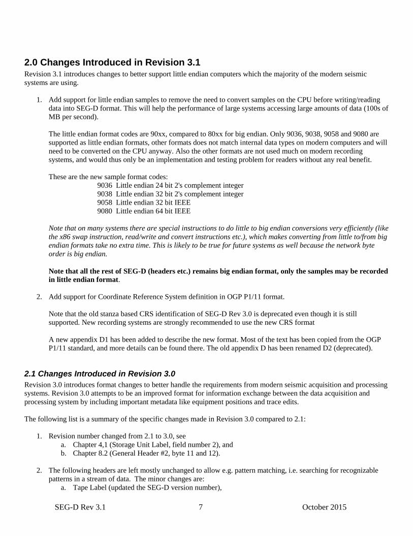
2.0 Changes Introduced in Revision 3.1 Revision 3.1 introduces changes to better support little endian computers which the majority of the modern seismic
systems are using.
1. Add support for little endian samples to remove the need to convert samples on the CPU before writing/reading
data into SEG-D format. This will help the performance of large systems accessing large amounts of data (100s of
MB per second).
The little endian format codes are 90xx, compared to 80xx for big endian. Only 9036, 9038, 9058 and 9080 are
supported as little endian formats, other formats does not match internal data types on modern computers and will
need to be converted on the CPU anyway. Also the other formats are not used much on modern recording
systems, and would thus only be an implementation and testing problem for readers without any real benefit.
These are the new sample format codes:
9036 Little endian 24 bit 2's complement integer
9038 Little endian 32 bit 2's complement integer
9058 Little endian 32 bit IEEE
9080 Little endian 64 bit IEEE
Note that on many systems there are special instructions to do little to big endian conversions very efficiently (like
the x86 swap instruction, read/write and convert instructions etc.), which makes converting from little to/from big
endian formats take no extra time. This is likely to be true for future systems as well because the network byte
order is big endian.
Note that all the rest of SEG-D (headers etc.) remains big endian format, only the samples may be recorded
in little endian format.
2. Add support for Coordinate Reference System definition in OGP P1/11 format.
Note that the old stanza based CRS identification of SEG-D Rev 3.0 is deprecated even though it is still
supported. New recording systems are strongly recommended to use the new CRS format
A new appendix D1 has been added to describe the new format. Most of the text has been copied from the OGP
P1/11 standard, and more details can be found there. The old appendix D has been renamed D2 (deprecated).
2.1 Changes Introduced in Revision 3.0
Revision 3.0 introduces format changes to better handle the requirements from modern seismic acquisition and processing
systems. Revision 3.0 attempts to be an improved format for information exchange between the data acquisition and
processing system by including important metadata like equipment positions and trace edits.
The following list is a summary of the specific changes made in Revision 3.0 compared to 2.1:
1. Revision number changed from 2.1 to 3.0, see
a. Chapter 4,1 (Storage Unit Label, field number 2), and
b. Chapter 8.2 (General Header #2, byte 11 and 12).
2. The following headers are left mostly unchanged to allow e.g. pattern matching, i.e. searching for recognizable
patterns in a stream of data. The minor changes are:
a. Tape Label (updated the SEG-D version number),

SEG-D Rev 3.1 8 October 2015
b. General Header #1 (allow FF16 as value of byte 23, to support different base scan intervals), and
c. Demux Trace Header (allow FFFF16 as value in bytes 5 and 6, to support extended trace number).
3. Rev 3.0 no longer requires a channel set to be present, making it possible to store a SEG-D record without any
data. This supports creating a SEG-D record with only header data, e.g. only External, Extended, and/or General
Trailer, which is useful for transferring metadata between systems.
4. Rev. 3.0 allows traces of zero length (no samples). This is done by setting start and end time to the same value,
and setting number of samples to 0 (Byte 13–16 of Channel Set Descriptor). This supports transfer of Trace
Header meta data between systems without any data attached.
5. Rev 3.0 is still a shot domain format; however a separate mode, Extended Recording Mode, has been added to
partially support non-shot domain data.
6. A high-resolution timestamp is introduced to accurately determine the time in SEG-D. The time of first sample in
record is entered in General Header #3 (Bytes 1–8). Position measurements, orientation measurements, source
events, etc. all have a timestamp attached, which allows multiple measurements of the same type to be stored
within the same record and trace header. This gives the manufacturer a much more fine grained control over, for
example, the movement of equipment during the record, and allows the use of modern, more powerful filtering
techniques to be applied to the data traces.
7. A SEG-D positioning format has been defined, and Position blocks may be inserted into Trace Headers. The
datum and projection information is inserted as part of the General Header. A single SEG-D record should only
contain one datum/projection, though a second geographic coordinate system (with same datum as the projected
CRS) may also be used. Multiple datums/projections may exist for a given storage unit (tape), however it is
recommended to not vary the coordinate system definitions as this increases the likelihood of errors in usage of
the data.
8. Rev 3.0 has an extended indexing structure, allowing more advanced logical addressing of traces, and better
grouping of information. The following indexes are supported for sources and receivers: Line, Point, Point Index,
Depth, Group and Re-shoot index.
9. An orientation header has been defined to properly support multi-component data. The format supports rotation to
a global reference system as part of acquisition, or to be applied later in processing. The rotation specified in the
orientation header may or may not be applied as part of acquisition. The Trace type and Line, Point and Group
indexes are used to determine which traces should be rotated together.
10. Rev 3.0 supports an increased range of sampling intervals, record lengths, number of channels, filter resolution,
etc. compared to Rev 2.x, to be able to handle the requirements of modern acquisition systems. In addition
negative times for start of trace are now supported.
11. The size of header, data, record etc. are now explicitly stated in General Header to facilitate quick data access and
facilitate error recovery.
12. All header blocks have an enumerated type attached (byte 32 of all blocks), both to increase flexibility of the
format to and simplify decoding. This also allows all information to be optional, simplifies error recovery and
increases the robustness of the format. In addition, it allows information to be inserted in the header and order
deemed most useful by the recorder.
13. The Channel Set Header has been extended to 96 bytes to support extended sampling intervals, trace lengths, etc.
All values are now explicitly stated, no complex calculation is required to determine, e.g., sampling interval or
descale multiplier. In addition derived values, such as the number of samples per channel, are also explicitly
SEG-D Rev 3.1 9 October 2015
stated to avoid ambiguities of prior versions of the SEG-D standard. A recorder-defined textual description has
been added to the channel set descriptor to increase the flexibility of the storage format and increase the efficiency
of information transfer between acquisition and processing.
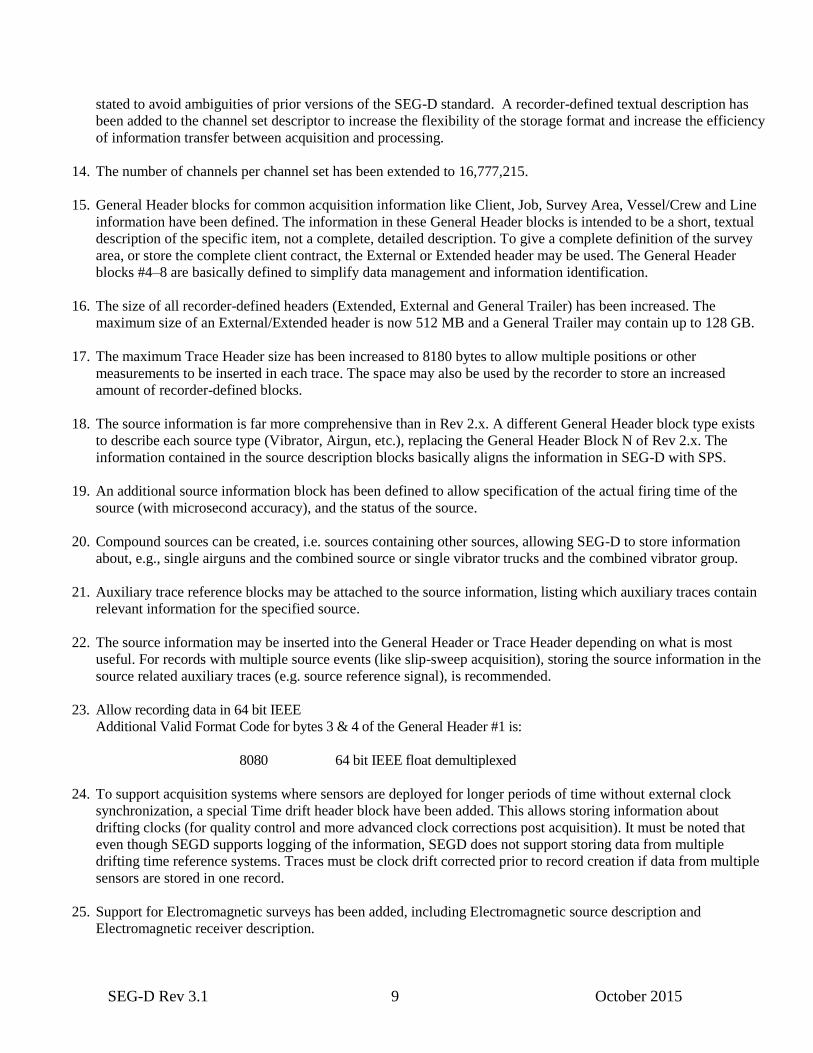
14. The number of channels per channel set has been extended to 16,777,215.
15. General Header blocks for common acquisition information like Client, Job, Survey Area, Vessel/Crew and Line
information have been defined. The information in these General Header blocks is intended to be a short, textual
description of the specific item, not a complete, detailed description. To give a complete definition of the survey
area, or store the complete client contract, the External or Extended header may be used. The General Header
blocks #4–8 are basically defined to simplify data management and information identification.
16. The size of all recorder-defined headers (Extended, External and General Trailer) has been increased. The
maximum size of an External/Extended header is now 512 MB and a General Trailer may contain up to 128 GB.
17. The maximum Trace Header size has been increased to 8180 bytes to allow multiple positions or other
measurements to be inserted in each trace. The space may also be used by the recorder to store an increased
amount of recorder-defined blocks.
18. The source information is far more comprehensive than in Rev 2.x. A different General Header block type exists
to describe each source type (Vibrator, Airgun, etc.), replacing the General Header Block N of Rev 2.x. The
information contained in the source description blocks basically aligns the information in SEG-D with SPS.
19. An additional source information block has been defined to allow specification of the actual firing time of the
source (with microsecond accuracy), and the status of the source.
20. Compound sources can be created, i.e. sources containing other sources, allowing SEG-D to store information
about, e.g., single airguns and the combined source or single vibrator trucks and the combined vibrator group.
21. Auxiliary trace reference blocks may be attached to the source information, listing which auxiliary traces contain
relevant information for the specified source.
22. The source information may be inserted into the General Header or Trace Header depending on what is most
useful. For records with multiple source events (like slip-sweep acquisition), storing the source information in the
source related auxiliary traces (e.g. source reference signal), is recommended.
23. Allow recording data in 64 bit IEEE
Additional Valid Format Code for bytes 3 & 4 of the General Header #1 is:
8080 64 bit IEEE float demultiplexed
24. To support acquisition systems where sensors are deployed for longer periods of time without external clock
synchronization, a special Time drift header block have been added. This allows storing information about
drifting clocks (for quality control and more advanced clock corrections post acquisition). It must be noted that
even though SEGD supports logging of the information, SEGD does not support storing data from multiple
drifting time reference systems. Traces must be clock drift corrected prior to record creation if data from multiple
sensors are stored in one record.
25. Support for Electromagnetic surveys has been added, including Electromagnetic source description and
Electromagnetic receiver description.

SEG-D Rev 3.1 10 October 2015
26. Sensor calibration information may now be added. SEGD supports an individual scaling factor, as part of the
sensor sensitivity value, and a more complex calibration function in frequency or time domain. The function can
either be specified as part of the trace header (frequency domain), or as a separate calibration “trace” (time
domain).
27. A set of standard measurements may now be added to a special Measurement header block, which may be
inserted into a trace header. Multiple measurement blocks may be used in any trace. Supported measurements are
depth, temperature, pressure, wind speed, altitude, uphole time, etc. Note: The format of the Measurement block
is still not finalized, discussions still ongoing with Energistics regarding the contents.
28. The General Trailer format has been completely changed from that of Rev 2.x. The new General Trailer format
consists of a number of blocks of data, each a multiple of 32 bytes, and starting with a 32 byte description header.
Any binary or ASCII block data may be stored unmodified as part of the General Trailer, as long as the block is
padded with zeros (0x00 – for binary data) or spaces (0x20 – for ASCII data) until it is a multiple of 32 bytes
long.
29. An edit format has been defined as part of the General Trailer, to simplify addition of post acquisition edit records
(e.g. by quality control or processing systems), to standardize transfer of edit information between acquisition and
processing. The format is based on the SEG ADS Trace Edit format (Norris et. al. 1999).
30. Storing positioning files like P1 and P2 as part of the General Trailer (for backup purposes), has been
standardized.
31. Some other simple Trailer blocks, like Observer Log and Text Comments have also been defined.
32. Several examples have been added to Appendix E.
33. Revision 2.x Appendix D “Header Descriptors” has been removed.
34. Appendix F, which previously listed specific tape drives and corresponding maximum block sizes, has been
removed. SEG-D revision 3.0 supports data on any fixed block, variable block and byte stream device including
tapes, disks, DVDs, and network connections with record sizes up to any specific device, operating system, file
system, or network limits. The plan is to keep information regarding specific devices, their block sizes and
recommended usage in the Technical Standards pages on http://www.seg.org. This will allow keeping the
information up to date without modifying the standards document.
35. A new Appendix F containing a snapshot of the Energistics Unit of Measure integer codes has been added. These
codes are used in the new standard Measurement block.
2.2 Changes Introduced in Revision 2.1
The following list discusses each of the specific changes made in Revision 2.1 compared to Revision 2.0.
1. Revision number changed from 2.0 to 2.1, see
- Chapter 4, field number 2
- Chapter 8.2 (General Header # 2, byte 11 and 12).
2. Since Rev 2.1 is intended to handle ultra high density tapes, acceptable media is expanded to include:
STK 9940B, IBM 3592 (Jaguar-1) and IBM TS1120 (Jaguar-2).

SEG-D Rev 3.1 11 October 2015
For further details, see Appendix F.
3. More than one production line per tape is allowed, as long as a unique combination of field file number and a new
line sequence number are used per storage unit.
The sequence number was added to General Header # 2, byte 21–22. Range is 1–65535 (Set to 0 if not valid).
4. Appendix A is updated (Manufacturers of Seismic Field Recorders).
5. Appendix C is updated (API Producer Organization Codes). Organization codes are now assigned by POSC which
maintains the current list of codes (API in previous revision).
6. Producer organization code is no longer a required field.

SEG-D Rev 3.1 12 October 2015
2.3 Changes Introduced in Rev 2.0
The following list discusses each of the specific changes made in Revision 2.0 compared to Revision 1.0. Also
mentioned are changes which were discussed as potential changes to be included in Rev 2.0, but were not included in
Rev 2.0.
1. Since Rev 2.0 is intended to handle higher density tapes, acceptable media is expanded to include: 3490/3490E,
3590, D2, and D3.
2. It is not anticipated that the higher density drives will be used to record multiplexed data. Rev 2.0 does not
support multiplexed data.
3. No specific changes will be made to SEG-D to handle “non-shot domain” data. Either a new committee should
be formed, or the charter of this committee should be extended to develop a new format for this application. It
does not appear practical to extend SEG-D to fit this application.
4. No special arrangements will be made to provide a standard method of recording SPS in the SEG-D header. The
relevant portions of SPS can be put into existing header extensions in user defined positions.
5. The MP factor description will be modified to clarify the meaning for fixed bit data (see MP discussion in
section 7).
6. The description of byte 12 in the General Header is being clarified to clearly state that the byte defines the
number of additional blocks. Figure 4 in the SEG-D Rev 1 document will be changed from # BLKS IN GEN
HDR to “# Additional blks in Gen Hdr”. Another correction will be made to correctly state, for byte 1 of the
General Header, “File number of four digits (0–9999) set to FFFF (Hex) when the file number is greater than
9999.
7. The RECEIVER LINE NUMBER (bytes 1–3) and RECEIVER POINT NUMBER (Bytes 4–6) in the Trace
Header Extension have been modified to include a fractional component. An all one’s pattern (FFFFFF16) in
either of these fields, will serve as a flag to indicate that the complete five byte value will be located in newly
defined locations in the Trace Header Extension. See Trace Header Extension table below.
8. The maximum number of Trace Header Extensions is now limited to 15.
9. Channels within the same Channel Set must now have the same number of Trace Header Extensions. Since all
traces within a Channel Set will now contain the same number of Trace Header Extensions, the number of
Trace Header Extensions will be indicated in the Channel Set Descriptor. The previously unused nibble of Byte
29 in the Channel Set Descriptor will now be defined to be a 4 bit binary parameter that defines the number of
Trace Header Extensions for that Channel Set. Byte 29 of the Channel Set descriptor will now be:
0 1 2 3 4 5 6 7
EFH3 EFH2 EFH1 EFH0 THE3 THE2 THE1 THE0
As a result of this limitation the Trace Header Extension field in Byte 10 of the Trace Header will also be
redefined as a 4 bit value limited to a maximum of 15 Trace Header Extensions.
10. The length of each trace within a Channel Set is now restricted to be the same value. This limitation and the
restricting the number of Trace Header Extensions to the same number within a Channel Set will result in each
trace within a Channel Set being recorded with the same number of bytes.
11. A tape label will be required on each tape. The details of this label format are described in section 4.
SEG-D Rev 3.1 13 October 2015
12. Data may be recorded in large logical blocks to maximize the transfer rates with high density tape systems. 3
types of device structures are supported:
A) Variable block length devices.
Every shot record must be aligned on a block boundary (i.e. each block will contain data from only one shot
record). Multiple channel sets may be included in each block. When the data to be recorded in a block contains
less than the maximum number of bytes in the block, there will be no padding characters to fill the block.
Storage Unit Structure in field 3 in Storage Unit Label must contain the text “RECORD”
B) Byte stream devices
There is no concept of a block, even though there is a hidden underlying physical block structure. Within each
file, one or more shot records are written consecutively without any gap.
Storage Unit Structure in field 3 in Storage Unit Label must contain the text “RECORD”
C) Fixed block length devices
Every shot record must be aligned on a block boundary (i.e. each block will contain data from only one shot
record). Multiple channel sets may be included in each block. Typically the last block in a shot record will
contain less data than the block size, the remaining part of this block will be padded with characters without any
information.
Storage Unit Structure in field 3 in Storage Unit Label must contain the text “FIXREC” and the block size is
found in field 5 in Storage Unit Label.
Note: Structure A can be mapped to a file directly but one can not re-generate the same interblock gaps and
File Marks from data stored on a file. Structure B and C can be mapped to a file directly and the structure can be
re-generated apart from the original position of the File Marks.
13. An appendix will be added to indicate the maximum allowable block size for accepted types of media. It is
expected that this table will need to be updated approximately once per year.
14. Byte 12 of the Trace Header will have an additional option, TR= 03 Trace has been edited. This parameter will
indicate the acquisition system has modified one or more samples of this trace. During data acquisition, if a
telemetry error occurs, a sample may be corrupted. Some radio acquisition systems fill in this missing data with
a copy of the previous sample, or interpolate to fill in the missing sample. Trace edit can also occur when a
noise edit process is applied by the acquisition system. The TR=03 flag should be set for those traces which
have been modified by the acquisition system.
15. The SEG-D, Rev 2.0 format treats data going to tape as a byte stream. File Marks are not required to separate
shot records, however File Marks may be included in between shot records where appropriate to ease error
recovery and/or to provide logical partitioning of the data. If used, File Marks may only be recorded at shot
record boundaries. For field tapes, File Marks should be written as frequently as possible, preferably for every
shot. If data is staged on disk, many shots can be stored in each file. When SEG-D, Rev 2.0 data is recorded on
tape, an EOD mark must be recorded after the last valid record and prior to the end of tape
16. The time standard referenced by byte 14 of the General Header has been changed from GMT to UTC.
17. Partitioning of a tape or other type media volume is now allowed. Each partition, or each tape if not partitioned,
constitutes one storage unit. The storage unit label shall consist of the first 128 bytes of the first user-writable
tape record in the first user-writable physical block and may, optionally, be followed by a File Mark. No File
Mark shall be written before the storage unit label.

SEG-D Rev 3.1 14 October 2015
18. Added a field in the Trace Header extension to indicate the type of sensor used for that trace (Byte 21).
2.4 Changes Introduced in Rev 1
In 1994, several changes were introduced to SEG-D to increase flexibility. These changes are listed below.
1. To allow for additional defined fields in SEG-D headers, additional blocks are allowed for the General Header and
Demux Trace Header.
2. Added provision for an optional set of General Trailer blocks. This type header allows provisions for recording
auxiliary seismic system and real-time navigation related data in the trailer. The trailer is optional and typically
follows all other recorded data.
The addition of the trailer will allow the accumulation of system faults, data QC information, real-time navigation
position, and timing information on the same tape, and contiguous with, the shotpoint that it relates to. By
recording this data after all of the other data, additional time is provided for collecting the data and transferring it to
the recording system.
The Trailer blocks take the same general form as the Channel Set Descriptor. Byte 11 uses the "Channel Type
Identification" set to 1100 to indicate a Trailer block. Bytes 1 and 2 indicate the number of the General Trailer
block, with the first block numbered as 1.
All other information in the trailer is optional and may be formatted as desired by the manufacturer/user.
The number of General Trailer blocks is indicated in bytes 13 and 14 of General Header Block #2.
3. Provide provision to include the revision of SEG-D format. Added to Bytes 11 and 12 of General Header Block #2
contain the SEG-D Revision Number. The revision number is a 16 bit unsigned binary number. The Revision
number is 1 for the proposed version.
In addition, in the General Header Block #1, nibble 1 of byte 12 contains the number of additional blocks in the
general header. Nibble 1, byte 12 is an unsigned binary number. This number will be 1 or greater for SEG D Rev
1.
4. Added provision to include the source and receiver locations for each source and receiver location. Source
locations are included in the General Header Blocks. Block #3 contains the position for Source Set #1. Additional
General Header Blocks may be included to allow for additional Source Sets.
Source positions are defined by a Source Line Number (three bytes integer and two bytes fraction), a Source Point
Number (three bytes integer and two bytes fraction), and a Source Point Index (one byte). This index allows several
locations for the source in the grid, the original value is 1 and that value is incremented by 1 every time the source is
moved, even when it is moved back to a previous location).
Receiver locations are included in Trace Header Extensions to be used with Demux Trace Headers. Receiver
positions are defined by a Receiver Line Number (three integer bytes and two fraction bytes), a Receiver Point
Number (three bytes integer and two bytes fraction), and a Receiver Point Index (one byte). This index allows for
defining the receiver group in the grid, the original value is 1 and that value is incremented by 1 every time the
receiver is moved, even when it is moved back to the previous location.
5. Provide for the use of File Numbers greater than 9999. Bytes 1, 2, and 3 in General Header Block #2 allow for a
three byte, binary file number. When the file number is greater than 9999, bytes 1 and 2 in the General Header
Block #1 must be set to FFFF.

SEG-D Rev 3.1 15 October 2015
6. Provide for Extended Channel Sets/Scan Types. General Header Block #2 allows for a two byte, binary number of
Channel Sets/Scan Types in bytes 4 and 5. When using the Extended Channel Sets/Scan Types, byte 29 of General
Header #1 must be set to FF.
7. Provide for additional Extended and External Header blocks. General Header Block #2 bytes 6 and 7 (for Extended
Header blocks) and Bytes 8 and 9 (for External Header blocks) allow the use of a two byte, binary number to allow
more than 99 blocks. When using these capabilities, General Header Block #1 byte 31 (for extended) and byte 32
(for external) must be set to FF.
8. Provide a mechanism for recording additional information about vibrator sources. Byte 15 of the General Header
Block #N indicates the signal used to control vibrator phase. Byte 16 indicates the type of vibrator (P, Shear,
Marine). Bytes 28 and 29 contain the phase angle between the pilot and the phase feedback signal.
The additional vibrator information may be recorded for multiple sets of sources by using additional General
Header blocks.
9. Provide for larger number of samples per trace. Using bytes 8, 9, and 10 of the Trace Header Extension.
10. Provide provisions for using 1/2" square tape cartridges. (ANSI X3.180 1989).
11. Allow recording data in IEEE and other new formats.
Additional Valid Format Codes for bytes 3 & 4 of the General Header are:
0036 24 bit 2's complement integer multiplexed
0038 32 bit 2's complement integer multiplexed
0058 32 bit IEEE multiplexed
8036 24 bit 2's complement integer demultiplexed
8038 32 bit 2's complement integer demultiplexed
8058 32 bit IEEE demultiplexed
The IEEE format is fully documented in the IEEE standard,
"ANSI/IEEE Std 754 - l985", available from the IEEE.
The IEEE format is summarized as follows:
Bit 0 1 2 3 4 5 6 7
Byte 1 S C7 C6 C5 C4 C3 C2 C1
Byte 2 C0 Q−1 Q−2 Q−3 Q−4 Q−5 Q−6 Q−7
Byte 3 Q−8 Q−9 Q−10 Q−11 Q−12 Q−13 Q−14 Q−15
Byte 4 Q−16 Q−17 Q−18 Q−19 Q−20 Q−21 Q−22 Q−23 (see Note 1)
The value (v) of a floating-point number represented in this format is determined as follows:
if e = 255 & f ≠ 0. .v = NaN Not-a-Number (see Note 2)
if e = 255 & f = 0. .v = (−1)s × Overflow
if 0 < e < 255. . . . . v = (−1)s × 2
e−127 × (1.f) Normalized
if e = 0 & f ≠ 0 . . . v = (−1)s × 2
e−126 × (0.f) Denormalized
if e = 0 & f = 0 . . . v = (−1)s × 0 ± zero
where e = binary value of all C's (exponent)
f = binary value of all Q's (fraction)
NOTES: 1. Bit 7 of byte 4 must be zero to guarantee uniqueness of the start of scan in the Multiplexed
format (0058). It may be non zero in the demultiplexed format (8058).

SEG-D Rev 3.1 16 October 2015
2. A Not-a-Number (NaN) is interpreted as an invalid number. All other numbers are valid and
interpreted as described above.
12. Allow for the use of blocked records. Allow blocked demultiplexed data (integral number of traces in a block).
Headers will not be blocked. All records in a block will be the same size. Not all blocks will be the same size.
Byte 20 in the general header (B1 = 1) will indicate blocked data. Blocks will be limited to 128 kilobytes. All
traces in a block are in the same Channel Set.
13. Added the effective stack order (unsigned binary), in byte 30 in the Channel Set descriptor. Set to 0 if the trace
data was intentionally set to real 0. Set to 1 if no stack. Set to the effective stack order if the data is the result of
stacked data (with or without processing).
14. Improved definition of undefined fields. All undefined fields will be specified as: "This field is undefined by
this format".
15. Added provisions for a Trace Edit byte (byte 10 of Demux Trace Header) to indicate traces zeroed for roll-on or
roll-off and to indicate deliberately zeroed traces.
TR=0 No edit of this trace
TR=1 Trace part of dead channels for roll-on or roll-off spread; trace intentionally zeroed.
TR=2 Trace intentionally zeroed.
16. Increased precision of MP factor, using byte 7 of the Channel Set descriptor.
17. Since modern seismic vessels record more than one streamer at a time, a standard convention is required to
identify which streamer recorded each channel of data. The Channel Set Descriptors are updated to handle this
task. The definition of a channel set is expanded to include the following rules. A channel set is a group of
channels that:
a) Use identical recording parameters. This includes the same record length and sampling interval.
b) Use identical processing parameters, including the same filter selection and array forming parameters.
A field has been added to Channel Set Descriptor byte 32 to describe any array forming applied to data
in that channel set.
c) Originates from the same streamer cable for marine data. The streamer cable number for each channel
set has been added to Channel Set Descriptor byte 31.
d) Consists of channels with the same group spacing. For example, if one steamer has short group spacing
close to the boat and longer groups spacing at long offsets, the data from that streamer would be
recorded as two channel sets.
In addition, the first channel in each channel set will start with Trace number one.
18. Correct the MP factor calculation (refer to Appendix E7 in the SEG-D recording format description.)
MP CALCULATION
The calculation of MP for a data recording method is given by one of the following equations:
(1) MP = FS − PA − Cmax; for binary exponents,
(2) MP = FS − PA − 2 x Cmax; for quaternary exponents,
(3) MP = FS − PA − 4 x Cmax; for hexadecimal exponents (except the 4 byte excess 64 method),
(4) MP = FS − PA − 4 x (Cmax − 64); for excess 64 hexadecimal exponents,
(5) MP = FS − PA − (Cmax − 127); for 32 bit IEEE exponents,
where
2FS
= Converter full scale (millivolts),
SEG-D Rev 3.1 17 October 2015
2PA
= Minimum system gain,
and
Cmax = maximum value of the data exponent,
Cmax = 15 for binary exponents,
7 for quaternary exponents,
3 for hexadecimal exponents except excess 64,
127 for excess 64 exponents, and
255 for 32 bit IEEE exponents.
19. Added the option for using record lengths in millisecond increments (rather than the previous 0.5 second
increments). The Extended Record Length is the record length, in unsigned binary milliseconds, and is recorded
in bytes 15–17 in General Header Block #2. If this option is used, Record Length (R), in the General Header
Block #1, bytes 26, 27 must be set to FFF.
SEG-D Rev 3.1 18 October 2015
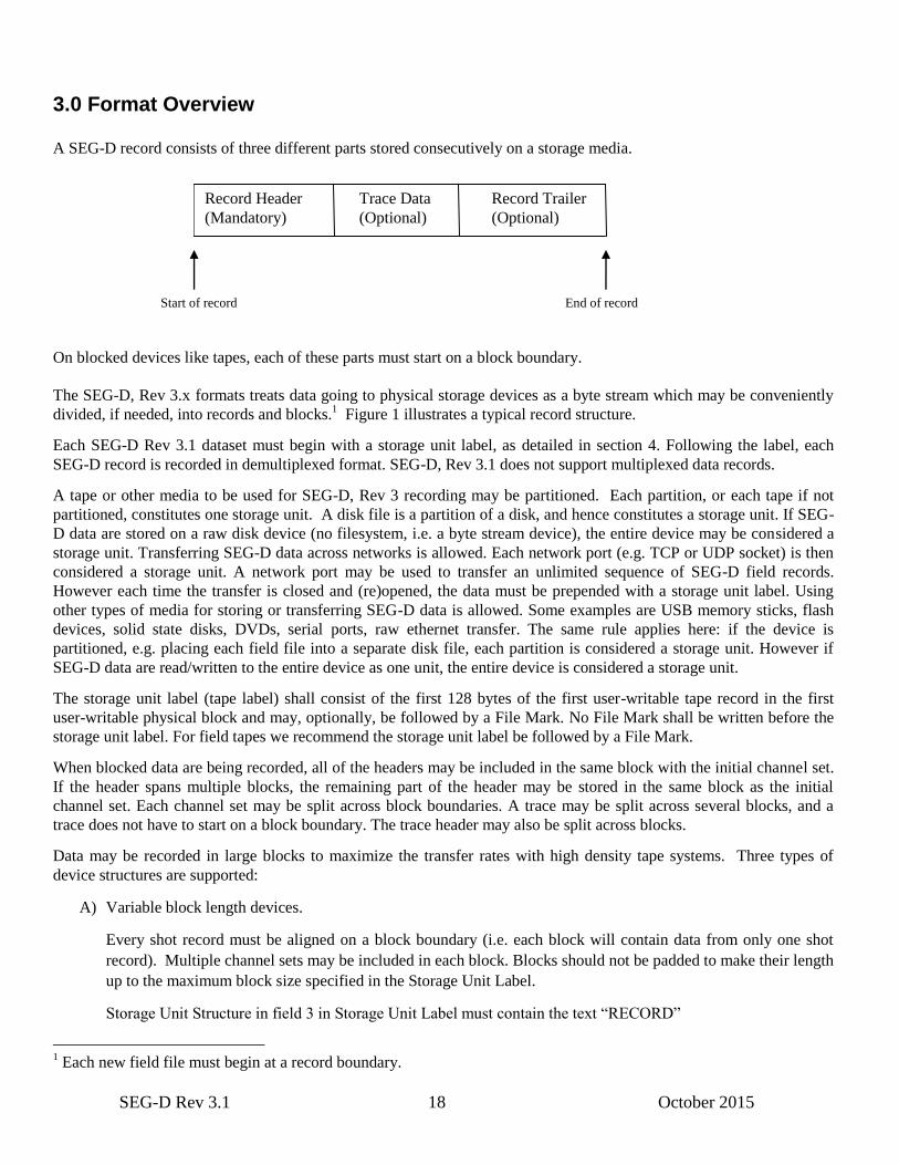
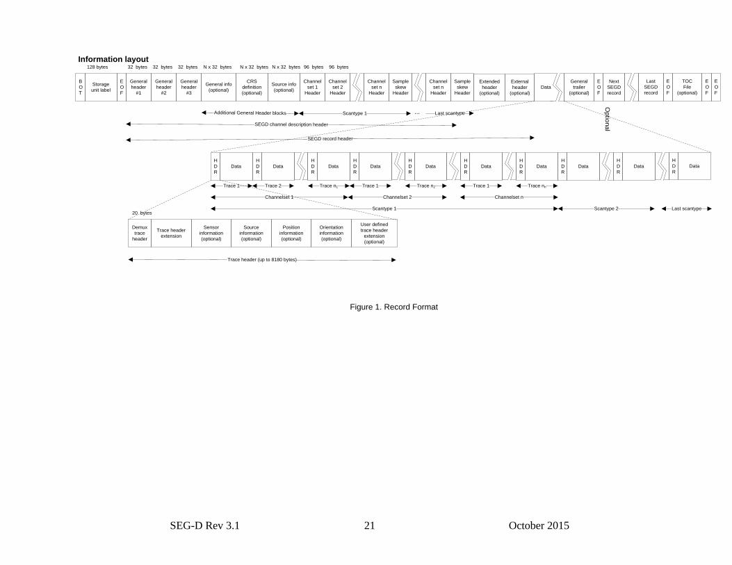
3.0 Format Overview
A SEG-D record consists of three different parts stored consecutively on a storage media.
On blocked devices like tapes, each of these parts must start on a block boundary.
The SEG-D, Rev 3.x formats treats data going to physical storage devices as a byte stream which may be conveniently
divided, if needed, into records and blocks.1 Figure 1 illustrates a typical record structure.
Each SEG-D Rev 3.1 dataset must begin with a storage unit label, as detailed in section 4. Following the label, each
SEG-D record is recorded in demultiplexed format. SEG-D, Rev 3.1 does not support multiplexed data records.
A tape or other media to be used for SEG-D, Rev 3 recording may be partitioned. Each partition, or each tape if not
partitioned, constitutes one storage unit. A disk file is a partition of a disk, and hence constitutes a storage unit. If SEG-
D data are stored on a raw disk device (no filesystem, i.e. a byte stream device), the entire device may be considered a
storage unit. Transferring SEG-D data across networks is allowed. Each network port (e.g. TCP or UDP socket) is then
considered a storage unit. A network port may be used to transfer an unlimited sequence of SEG-D field records.
However each time the transfer is closed and (re)opened, the data must be prepended with a storage unit label. Using
other types of media for storing or transferring SEG-D data is allowed. Some examples are USB memory sticks, flash
devices, solid state disks, DVDs, serial ports, raw ethernet transfer. The same rule applies here: if the device is
partitioned, e.g. placing each field file into a separate disk file, each partition is considered a storage unit. However if
SEG-D data are read/written to the entire device as one unit, the entire device is considered a storage unit.
The storage unit label (tape label) shall consist of the first 128 bytes of the first user-writable tape record in the first
user-writable physical block and may, optionally, be followed by a File Mark. No File Mark shall be written before the
storage unit label. For field tapes we recommend the storage unit label be followed by a File Mark.
When blocked data are being recorded, all of the headers may be included in the same block with the initial channel set.
If the header spans multiple blocks, the remaining part of the header may be stored in the same block as the initial
channel set. Each channel set may be split across block boundaries. A trace may be split across several blocks, and a
trace does not have to start on a block boundary. The trace header may also be split across blocks.
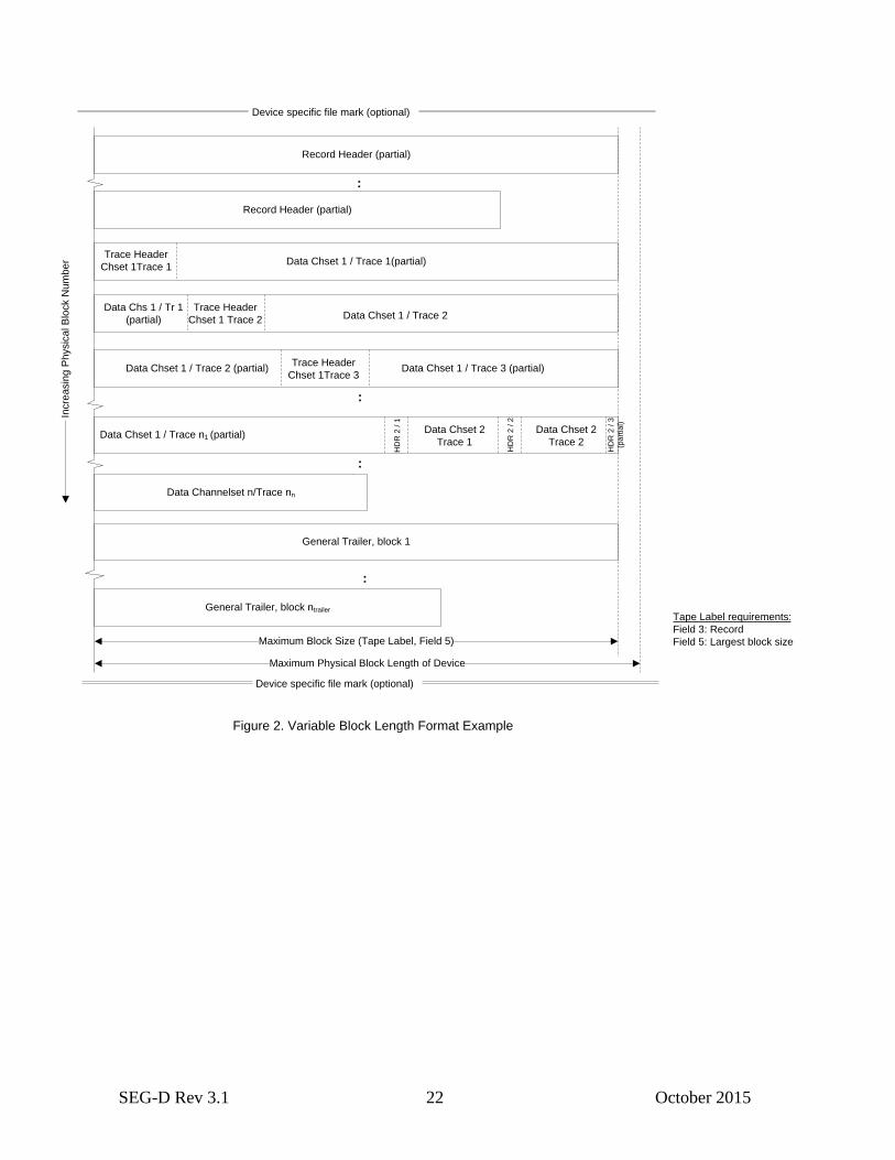
Data may be recorded in large blocks to maximize the transfer rates with high density tape systems. Three types of
device structures are supported:
A) Variable block length devices.
Every shot record must be aligned on a block boundary (i.e. each block will contain data from only one shot
record). Multiple channel sets may be included in each block. Blocks should not be padded to make their length
up to the maximum block size specified in the Storage Unit Label.
Storage Unit Structure in field 3 in Storage Unit Label must contain the text “RECORD”
1 Each new field file must begin at a record boundary.
Record Header
(Mandatory)
Trace Data
(Optional)
Record Trailer
(Optional)
Start of record End of record

SEG-D Rev 3.1 19 October 2015
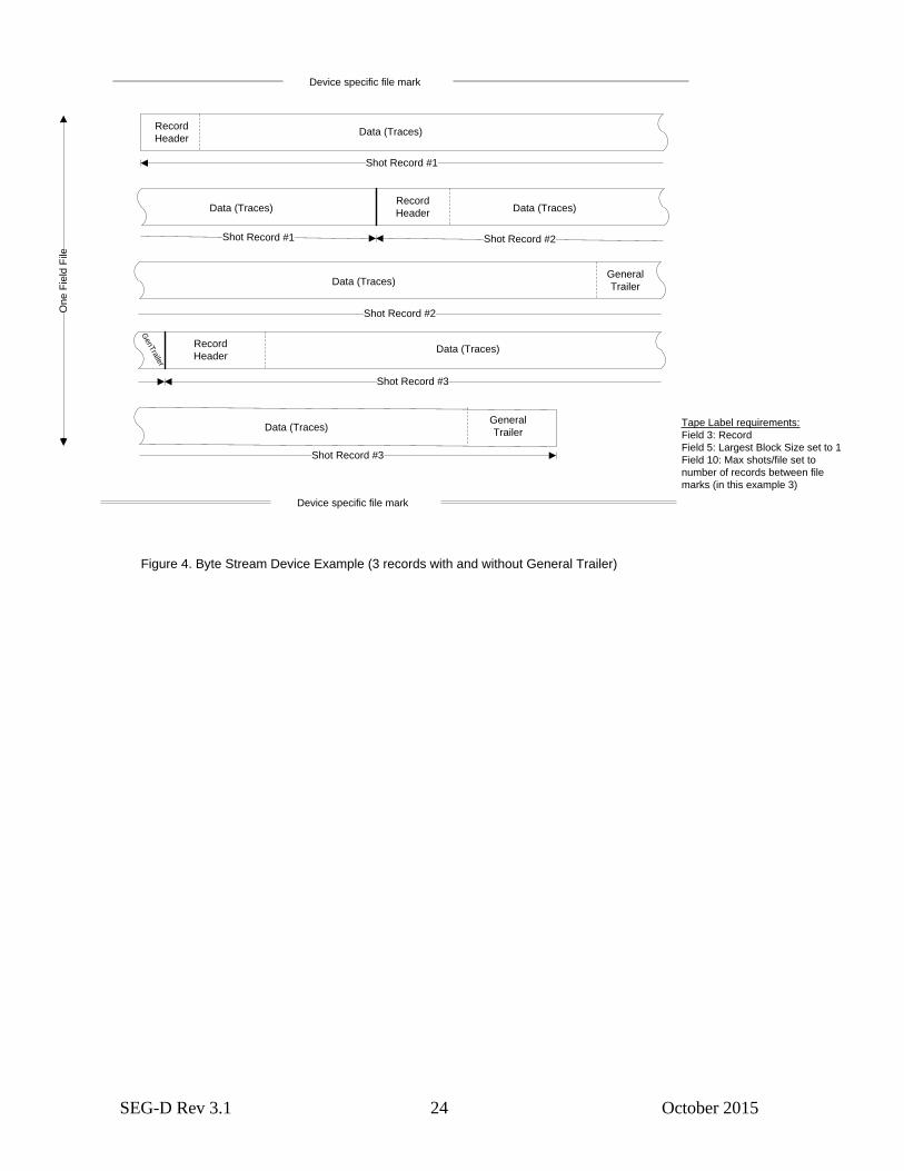
B) Byte stream devices
There is no concept of a block, even though there is a hidden underlying physical block structure. Within each
file, one or more shot records are written consecutively without any gap.
Storage Unit Structure in field 3 in Storage Unit Label must contain the text “RECORD”, and Maximum Block
Size should be set to 1.
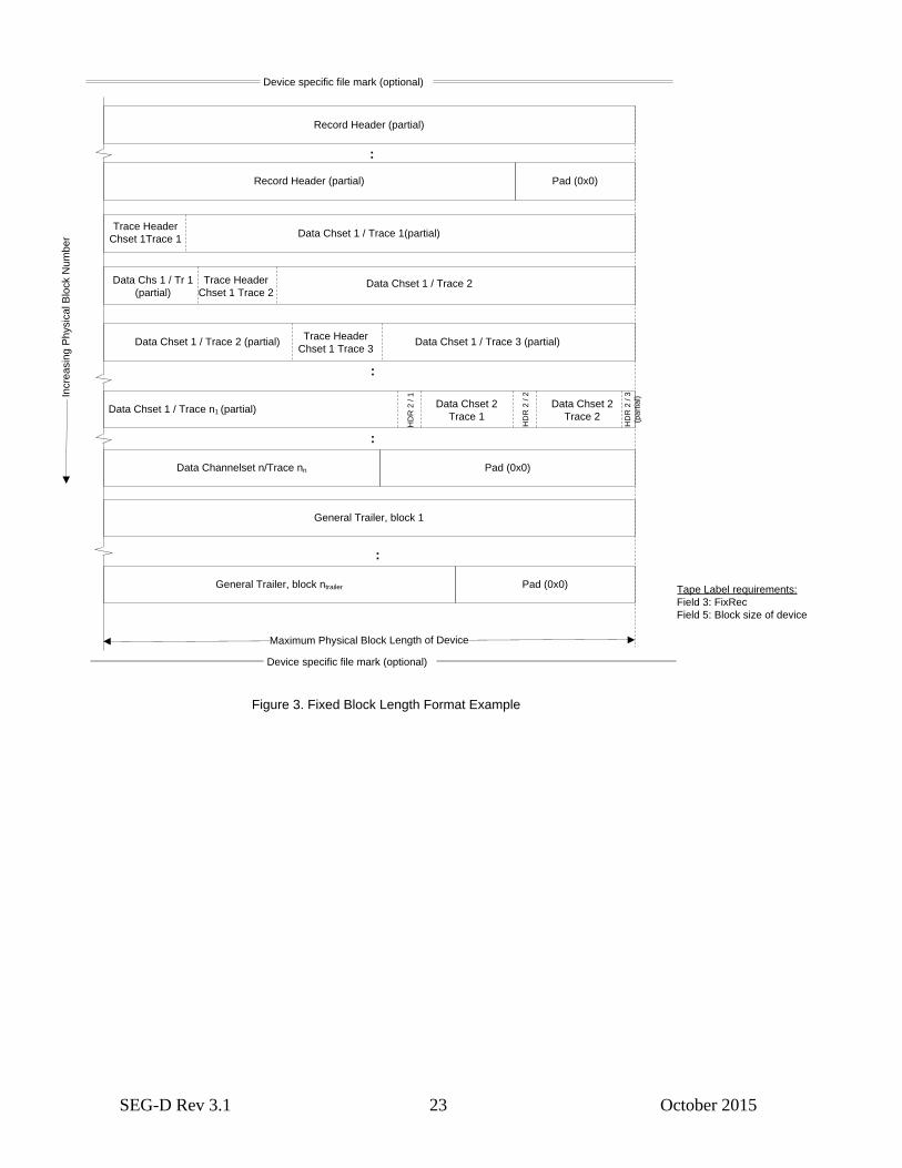
C) Fixed block length devices
Every shot record must be aligned on a block boundary (i.e. each block will contain data from only one shot
record). Multiple channel sets may be included in each block. Typically the last block in a shot record will
contain less data than the block size, the remaining part of this block will be padded with characters without any
information.
Storage Unit Structure in Field 3 in Storage Unit Label must contain the text “FIXREC” and the block size is
found in Field 5 in Storage Unit Label.
Note: Structure A can be mapped to a file directly but one cannot re-generate the same inter-block gaps (if
present) and File Marks from data stored on a file. Structure B and C can be mapped to a file directly and the
structure can be re-generated apart from the original position of the File Marks.
The SEG-D, Rev 3.0 format treats data going to tape as a byte stream. File Marks are not required to separate shot
records, however File Marks may be included between shot records where appropriate to ease error recovery and/or to
provide logical partitioning of the data. If used, File Marks may only be recorded at shot record boundaries. For field
tapes, File Marks should be written as frequently as possible, preferably for every shot. If data are staged on disk, many
shots can be stored in each file. When SEG-D, Rev 3.0 data are recorded on tape, an EOD mark must be recorded after
that last valid record and prior to the end of tape.
If the tape media supports multiple partitions, SEG-D data may be written to any of the partitions of the tape, each
beginning with a Storage Unit Label. Data from one partition cannot “run-over” into a subsequent partition, each
partition must be capable of being decoded in isolation.
On one tape, it is allowable to mix partitions containing SEG-D data with partitions containing non SEG-D formatted
information.
The headers of SEG-D Rev 3.0 can be very large compared to previous versions of the format. The maximum for each
of the main header types are shown below:
General Header: 2,097,120 bytes ~ 2 MB
Skew headers: 2,097,120 bytes ~ 2 MB
Scan type header/Channel Set descriptors: 6,291,360 bytes ~ 6 MB per scan type (up to 99 scan types)
Extended Header: 536,870,880 bytes ~ 512 MB
External Header: 536,870,880 bytes ~ 512 MB
General Trailer: 137,438,953,440 bytes ~ 128 GB
Trace Header: 8,180 bytes ~ 8 kB
In addition, the maximum trace size is
Trace: 8,180 (header) + 34,359,738,360 (data) bytes ~ 32 GB
Note: The headers and traces may therefore span multiple tape blocks.
SEG-D Rev 3.1 20 October 2015
SEGD Rev 3.0 disconnects tape blocks from data blocks completely, the start of a header block/start of trace may be
anywhere in a tape block. A header may also be split between two tape blocks, e.g. a trace header may have just one
byte in one tape block, and the rest continuing in the next block.
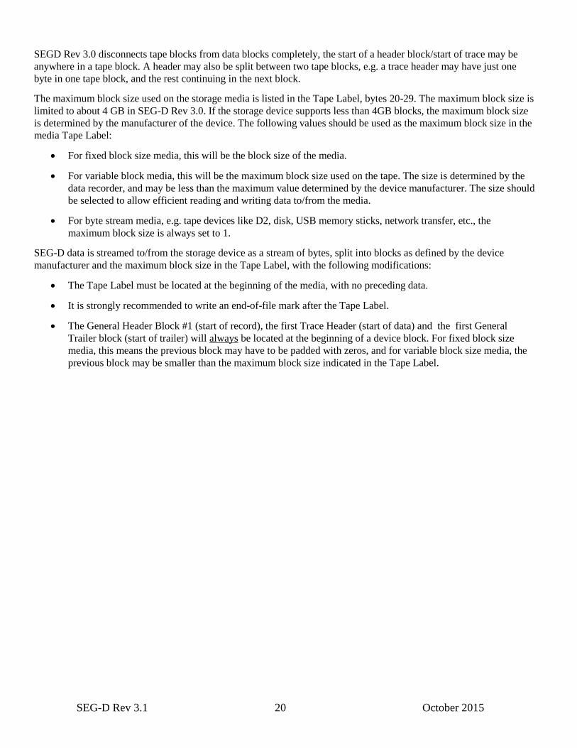
The maximum block size used on the storage media is listed in the Tape Label, bytes 20-29. The maximum block size is
limited to about 4 GB in SEG-D Rev 3.0. If the storage device supports less than 4GB blocks, the maximum block size
is determined by the manufacturer of the device. The following values should be used as the maximum block size in the
media Tape Label:
For fixed block size media, this will be the block size of the media.
For variable block media, this will be the maximum block size used on the tape. The size is determined by the
data recorder, and may be less than the maximum value determined by the device manufacturer. The size should
be selected to allow efficient reading and writing data to/from the media.
For byte stream media, e.g. tape devices like D2, disk, USB memory sticks, network transfer, etc., the
maximum block size is always set to 1.
SEG-D data is streamed to/from the storage device as a stream of bytes, split into blocks as defined by the device
manufacturer and the maximum block size in the Tape Label, with the following modifications:
The Tape Label must be located at the beginning of the media, with no preceding data.
It is strongly recommended to write an end-of-file mark after the Tape Label.
The General Header Block #1 (start of record), the first Trace Header (start of data) and the first General
Trailer block (start of trailer) will always be located at the beginning of a device block. For fixed block size
media, this means the previous block may have to be padded with zeros, and for variable block size media, the
previous block may be smaller than the maximum block size indicated in the Tape Label.
SEG-D Rev 3.1 21 October 2015
B
O
T
Storage
unit label
E
O
F
General
header
#1
General
header
#2
General info
(optional)
Source info
(optional)
Channel
set 1
Header
128 bytes 32 bytes 32 bytes N x 32 bytes N x 32 bytes
Channel
set 2
Header
Channel
set n
Header
Sample
skew
Header
Scantype 1
Channel
set n
Header
Sample
skew
Header
Last scantype
Extended
header
(optional)
External
header
(optional)
Data
General
trailer
(optional)
E
O
F
Next
SEGD
record
Op
tion
al
Last
SEGD
record
E
O
F
E
O
F
E
O
F
TOC
File
(optional)
SEGD record header
SEGD channel description header
H
D
R
Data
H
D
R
Data
H
D
R
Data
H
D
R
Data
Trace 1 Trace 2 Trace n1
H
D
R
Data
Trace n2Trace 1
Channelset 1 Channelset 2
Scantype 1
H
D
R
Data
H
D
R
Data
Trace nnTrace 1
Channelset n
H
D
R
Data
Scantype 2 Last scantype
Data
H
D
R
Data
H
D
R
Demux
trace
header
Trace header
extension
20 bytes
Position
information
(optional)
User defined
trace header
extension
(optional)
Trace header (up to 8180 bytes)
Source
information
(optional)
Information layout
General
header
#3
32 bytes 96 bytes 96 bytes
Orientation
information
(optional)
Sensor
information
(optional)
CRS
definition
(optional)
...
N x 32 bytes
Additional General Header blocks
Figure 1. Record Format
SEG-D Rev 3.1 22 October 2015
Device specific file mark (optional)
Device specific file mark (optional)
Tape Label requirements:
Field 3: Record
Field 5: Largest block size
Incre
asin
g P
hysic
al B
lock N
um
be
r
Maximum Physical Block Length of Device
Record Header (partial)
Record Header (partial)
Data Chset 1 / Trace 1(partial)
Data Chset 1 / Trace 2 (partial) Data Chset 1 / Trace 3 (partial)
:
Maximum Block Size (Tape Label, Field 5)
Data Chset 1 / Trace n1 (partial)
:
Data Channelset n/Trace nn
General Trailer, block 1
:
General Trailer, block ntrailer
Figure 2. Variable Block Length Format Example
:
Trace Header
Chset 1Trace 1
Trace Header
Chset 1 Trace 2
Trace Header
Chset 1Trace 3
Data Chs 1 / Tr 1
(partial) Data Chset 1 / Trace 2
HD
R 2
/ 1
HD
R 2
/ 2
HD
R 2
/ 3
(pa
rtia
l)
Data Chset 2
Trace 1
Data Chset 2
Trace 2
SEG-D Rev 3.1 23 October 2015
Device specific file mark (optional)
Device specific file mark (optional)
Tape Label requirements:
Field 3: FixRec
Field 5: Block size of device
Incre
asin
g P
hysic
al B
lock N
um
be
r
Maximum Physical Block Length of Device
Figure 3. Fixed Block Length Format Example
Pad (0x0)
Pad (0x0)
Pad (0x0)
Record Header (partial)
Record Header (partial)
Data Chset 1 / Trace 1(partial)
Data Chset 1 / Trace 2 (partial) Data Chset 1 / Trace 3 (partial)
:
Data Chset 1 / Trace n1 (partial)
:
Data Channelset n/Trace nn
General Trailer, block 1
:
General Trailer, block ntrailer
:
Trace Header
Chset 1Trace 1
Trace Header
Chset 1 Trace 2
Trace Header
Chset 1 Trace 3
Data Chs 1 / Tr 1
(partial)Data Chset 1 / Trace 2
HD
R 2
/ 1
HD
R 2
/ 2
HD
R 2
/ 3
(pa
rtia
l)
Data Chset 2
Trace 1
Data Chset 2
Trace 2
SEG-D Rev 3.1 24 October 2015
Device specific file mark
Tape Label requirements:
Field 3: Record
Field 5: Largest Block Size set to 1
Field 10: Max shots/file set to
number of records between file
marks (in this example 3)
Figure 4. Byte Stream Device Example (3 records with and without General Trailer)
On
e F
ield
File
Shot Record #1
Shot Record #1 Shot Record #2
General
Trailer
Shot Record #2
GenTra
iler
Shot Record #3
General
Trailer
Shot Record #3
Device specific file mark
Data (Traces)
Data (Traces) Data (Traces)
Data (Traces)
Data (Traces)
Data (Traces)
Record
Header
Record
Header
Record
Header
SEG-D Rev 3.1 25 October 2015
End of disk file
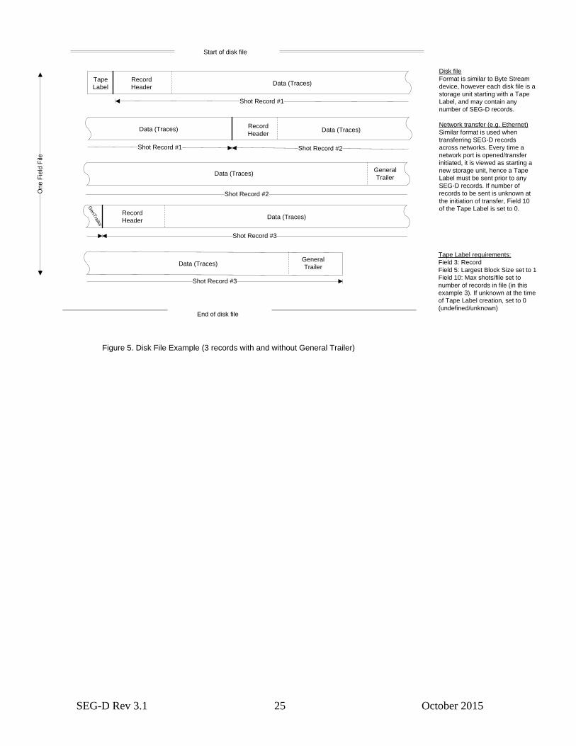
Tape Label requirements:
Field 3: Record
Field 5: Largest Block Size set to 1
Field 10: Max shots/file set to
number of records in file (in this
example 3). If unknown at the time
of Tape Label creation, set to 0
(undefined/unknown)
Figure 5. Disk File Example (3 records with and without General Trailer)
On
e F
ield
File
Record
Header
Shot Record #1
Shot Record #1 Shot Record #2
General
Trailer
Shot Record #2
GenTra
iler
Shot Record #3
General
Trailer
Shot Record #3
Start of disk file
Tape
Label
Disk file
Format is similar to Byte Stream
device, however each disk file is a
storage unit starting with a Tape
Label, and may contain any
number of SEG-D records.
Network transfer (e.g. Ethernet)
Similar format is used when
transferring SEG-D records
across networks. Every time a
network port is opened/transfer
initiated, it is viewed as starting a
new storage unit, hence a Tape
Label must be sent prior to any
SEG-D records. If number of
records to be sent is unknown at
the initiation of transfer, Field 10
of the Tape Label is set to 0.
Data (Traces)
Data (Traces) Data (Traces)
Data (Traces)
Data (Traces)
Data (Traces)
Record
Header
Record
Header

SEG-D Rev 3.1 26 October 2015
3.1 SEG-D timestamp
SEG-D Rev 3.1 supports a more accurate time stamp than provided by the earlier versions. (Rev. 2.x had only a
timestamp accurate to one second stored in General Header Block #1.) There is a need to be able to give each sample an
accurate timestamp, to be able to tie seismic data to external events, externally acquired data, or similar. Previously
every manufacturer had their own proprietary time format, e.g. by storing a timestamp as part of the Extended or
External Header. As of SEG-D Rev 3.0, a timestamp is stored in General Header Block #3, bytes 1 to 8. It is still
permissible to store timestamps as part of the External or Extended Header, however the official time of the SEG-D
record is now found in General Header Block #3.
Definition
A SEG-D Rev 3.0 timestamp is an 8 byte, signed, big-endian integer counting the number of microseconds since
6 Jan 1980 00:00:00 (GPS epoch). The timestamp is equal to GPS time converted to microseconds.
This 8 byte timestamp is heretofore referred to as a SEG-D timestamp.
The number range an 8 byte microsecond count supports is approximately 9223372036854 seconds or 292471 years.
Dates before 6 Jan 1980 00:00:00 will have negative timestamps. The earliest timestamp allowed in prior revisions of
SEG-D was 1 Jan 1970 00:00:00 (SEG-D epoch). See below for more details regarding conversion between timestamp
and UTC.
There are several reasons why GPS time has been selected as basis of SEG-D timestamp:
- Most seismic acquisition systems use GPS for positioning, and hence have GPS time easily available
- GPS time does not contain leap seconds, which would cause a problem for processing of any record crossing
leap second boundaries (remember, in Rev 3.1 measurements at several different times during the record may
exist). For this reason, UTC was not chosen as basis for timestamp.
- There are other time formats without leap seconds, such as International Atomic Time (TAI) which tracks
proper time on the Earth’s geoid; however GPS is more commonly used in seismic acquisition systems.
- There are proposals for redefinition of UTC (to eliminate leap seconds). This would cause problems for
handling historical data (i.e. tapes), as there would be a difference in definition before and after the change.
- Leap seconds are unpredictable (the Earth rotation speed changes at an unpredictable rate), so it is not possible
to create a mathematical formula to calculate leap second.
Relative Time Mode record
For recording systems without absolute time, the timestamp in General Header Block #3 (bytes 1 to 8) must be set to 0,
and the Relative Time Mode in General Header Block #3 (byte 30) set to 1. All timestamps in the record must then be
relative to start of record (time zero). If reference to absolute time is required for such a record, the manufacturer is
responsible for providing the required information separately.
The time stamp in General Header Block #1 can in Relative Time Mode either be set to 1 Jan 1970, an approximate
value of the actual time, or a relative time compared to other records in the survey, whatever the manufacturer
determines would best help interpretation of the data.

SEG-D Rev 3.1 27 October 2015
SEG-D timestamp and UTC conversion
There are a few problems with choosing GPS time as foundation for a SEG-D timestamp, mainly related to the
timestamp in General Header Block #1, which is UTC (Coordinated Universal Time) or GMT (Greenwich Mean Time).
This has not been changed in Rev. 3.0 for backward compatibility. However, when reading and writing SEG-D Rev 3.0
records, it is important to handle the differences, i.e. by adding the proper number of leap seconds.
GPS was aligned with UTC on 6 Jan 1980, but due to the variation in Earth’s rotation, the definition of seconds, etc.,
leap seconds have to be added to UTC. As of April 2009, UTC time is 15 seconds behind GPS time.
The sequence of dates of the UTC second markers during leap second is:
31 December 2005, 23h 59m 59s
31 December 2005, 23h 59m 60s
01 January 2006, 0h 0m 0s
Note: The interpretation of UTC timestamps needs to allow 60 as a value of seconds! This was previously not accounted
for in the Rev 2.x standard.
As GPS time is not defined prior to 6 Jan 1980, leap seconds are added to UTC as defined by International Atomic Time
(TAI) such that the SEG-D timestamp equals TAI time plus 19 seconds at the TAI epoch (1 Jan 1972 00:00:00). (The
reason for the 19 seconds difference is the TAI choice to start off with an initial difference to UTC of 10 seconds (TAI
was synchronized with UTC at the start of 1958, and has drifted ever since), then 9 leap seconds were added during the
1970s. As GPS time was synchronized to UTC 6 Jan 1980, GPS time is now running at a fixed 19 second difference to
TAI.)
Prior to 1970 no official leap seconds existed, so SEG-D defines for the purpose of timestamp/UTC conversions that no
leap seconds exist for 1970 and 1971 (this should have very few practical consequences).
UTC to SEG-D timestamp difference:
01 MAR 2008: UTC 14 seconds behind timestamp
06 JAN 1980: UTC equal to timestamp
01 JAN 1970: UTC 9 seconds ahead of timestamp
See Appendix E for examples of conversions between UTC and SEG-D timestamp.
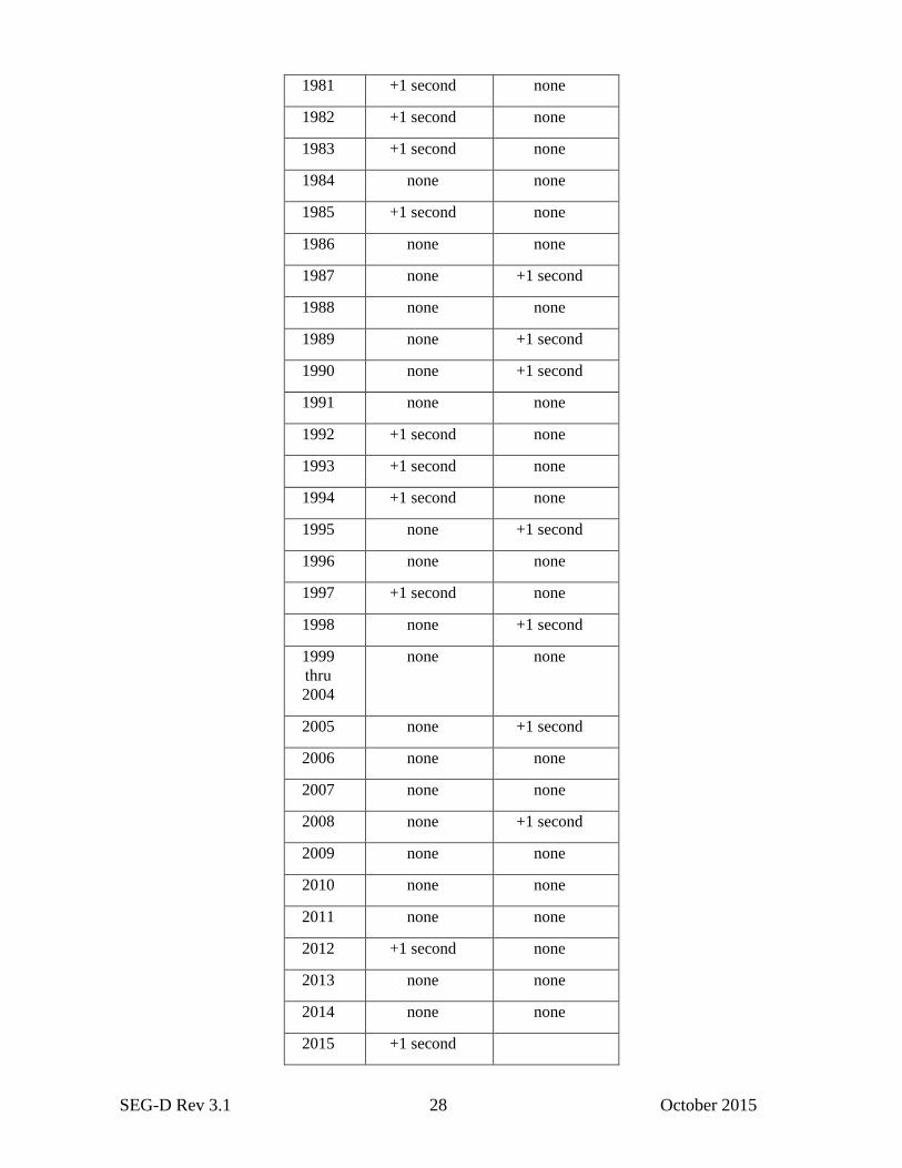
The table below shows leap seconds added to UTC time since 1970. Note the values for 1970 and 1971 (in italics) are
not according to international standards; they are just values used to allow conversion of dates back to 1 Jan 1970 (SEG-
D epoch):
Year 30 June 31 Dec
1970 none none
1971 none none
1972 +1 second +1 second
1973
thru
1979
none +1 second
each year
1980 none none
SEG-D Rev 3.1 28 October 2015
1981 +1 second none
1982 +1 second none
1983 +1 second none
1984 none none
1985 +1 second none
1986 none none
1987 none +1 second
1988 none none
1989 none +1 second
1990 none +1 second
1991 none none
1992 +1 second none
1993 +1 second none
1994 +1 second none
1995 none +1 second
1996 none none
1997 +1 second none
1998 none +1 second
1999
thru
2004
none none
2005 none +1 second
2006 none none
2007 none none
2008 none +1 second
2009 none none
2010 none none
2011 none none
2012 +1 second none
2013 none none
2014 none none
2015 +1 second
SEG-D Rev 3.1 29 October 2015
3.2 Multi-component data
Rev 2.x had limited support for multi-component data, but with several deficiencies. Rev 3.0 introduced several new
sensor types, and Position/Orientation header blocks to better cope with multi-component acquisition.
Multi-component data should be recorded with each component in separate channel sets, i.e. the X component in one
channel set, the Y component in another, etc. The component type must be clearly indicated in the Channel Set Header
and Trace Header Extension #1. The indices in Trace Header Extension #1 (i.e. receiver line/point/point index/group
index/depth index/reshoot index) will indicate which traces have to be processed together as a unit, e.g. for rotation. The
group index will indicate the component number. The sensor type will indicate which type of data each trace contains.
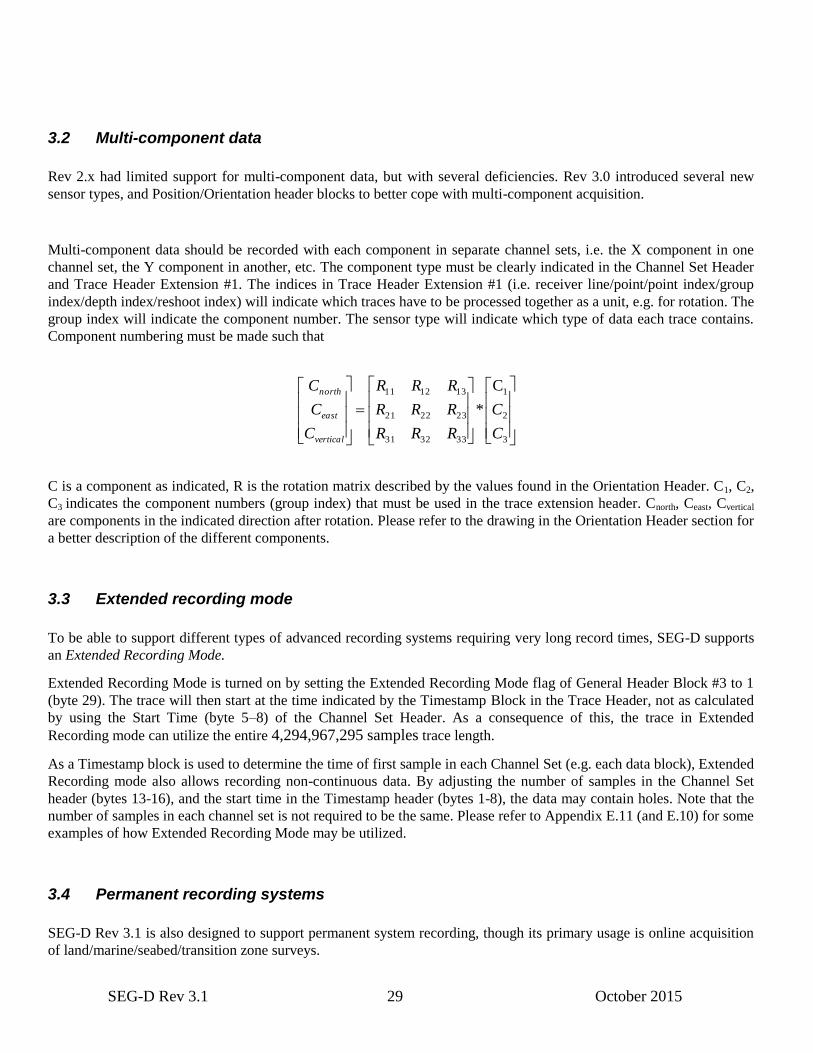
Component numbering must be made such that
3
2
1
333231
232221
131211 C
*
C
C
RRR
RRR
RRR
C
C
C
vertical
east
north
C is a component as indicated, R is the rotation matrix described by the values found in the Orientation Header. C1, C2,
C3 indicates the component numbers (group index) that must be used in the trace extension header. Cnorth, Ceast, Cvertical
are components in the indicated direction after rotation. Please refer to the drawing in the Orientation Header section for
a better description of the different components.
3.3 Extended recording mode
To be able to support different types of advanced recording systems requiring very long record times, SEG-D supports
an Extended Recording Mode.
Extended Recording Mode is turned on by setting the Extended Recording Mode flag of General Header Block #3 to 1
(byte 29). The trace will then start at the time indicated by the Timestamp Block in the Trace Header, not as calculated
by using the Start Time (byte 5–8) of the Channel Set Header. As a consequence of this, the trace in Extended
Recording mode can utilize the entire 4,294,967,295 samples trace length.
As a Timestamp block is used to determine the time of first sample in each Channel Set (e.g. each data block), Extended
Recording mode also allows recording non-continuous data. By adjusting the number of samples in the Channel Set
header (bytes 13-16), and the start time in the Timestamp header (bytes 1-8), the data may contain holes. Note that the
number of samples in each channel set is not required to be the same. Please refer to Appendix E.11 (and E.10) for some
examples of how Extended Recording Mode may be utilized.
3.4 Permanent recording systems
SEG-D Rev 3.1 is also designed to support permanent system recording, though its primary usage is online acquisition
of land/marine/seabed/transition zone surveys.
SEG-D Rev 3.1 30 October 2015
A permanent system consists of units with, typically, a few sensors and recording can last for days or even weeks.
SEG-D 3.1 supports traces of up to 2147 seconds in length. To record data for longer than this, multiple channel sets
must be used, i.e. the same traces continue into the next channel set. See Extended Recording Mode above. Multiple
traces from the same sensor are not allowed in one channel set, but it is not necessary to make a new scan type for the
next channel set. This allows recording of up to 4,294,967,295 samples per trace * 65535 (max number of channel
sets) = 281,470,681 seconds or approximately 3257 days with highest sample rate (1 microsecond). For a more
commonly used sample rate of 2 milliseconds, the maximum record length is increased to more than 17850 years. If
longer recording is required, multiple SEG-D records must be created. (Note: The example above assumes only one
channel type is recorded. If multiple channel types are needed, multiple channel sets must be created, and the maximum
record length will be reduced accordingly.)
The sizes of headers have been extended to support the extended amount of meta information required for permanent
surveys. Metadata recording incidents occurring throughout the record may appear as part of the External or Extended
Headers, inserted into the Trace Header Extension, or appended to the General Trailer. For devices with limited amount
of memory and CPU, the General Trailer option might be preferable. All metadata should be tagged with the SEG-D
timestamp (if time related), and/or scantype#/channel set#/trace# (if trace related, and information not recorded as part
of the Trace Header).
3.5 Time drift
Some acquisition systems deploy single sensor unit for long periods of time without synchronization with other parts of
the acquisition system or an external clock reference (e.g. GPS). Time drift (i.e. the clock running at a faster or slower rate
than GPS) is then a problem. SEGD supports recording the time drift for each individual trace in the Time Drift Header
block by storing the time of deployment and retrieval of the sensor, and the corresponding time offsets.
The data can then be time drift corrected using these values directly (linear time correction). If a more advanced time drift
correction is desired, the manufacturer is free to do so. The manufacturer must then provide the time drift correction
information in manufacturer specific header blocks or possibly other external data.
Trace data from a sensor unit may be recorded in SEGD format using a drifting clock, both in normal and extended
recording mode. However all channels within the record must have the same time drift (i.e. use the same time reference
system).
Note:
Trace data must be time drift corrected before merging trace data from multiple drifting sensor units into one single
SEGD record, i.e. start of trace must be aligned, and sample rate must be corrected. SEGD does not support irregular
(drifting) sample intervals or time skew between channels other than specified in the skew blocks and trace sample skew
values.
See Appendix E, EM survey, for more details regarding the time drift correction.
3.6 Positions in SEG-D
SEG-D allows for multiple coordinate tuples for any location. A coordinate tuple is an ordered set of coordinates
describing a position. For redundancy, two coordinate tuples can be given in different coordinate reference system types
for any position, e.g. geographic and projected. Coordinate reference system types are:
CRS Type Coordinate Field 1 Coordinate Field 2 Coordinate Field 3

SEG-D Rev 3.1 31 October 2015
Projected1 Easting or northing2 Northing or easting2 (not used, leave blank)
Geographic 2D Latitude Longitude (not used, leave blank)
Geographic 3D Latitude Longitude Ellipsoidal height
Geocentric Geocentric X Geocentric Y Geocentric Z
Vertical (not used, leave blank) (not used, leave blank) Gravity-related height or depth3
Engineering 1D4 Distance along X axis (not used, leave blank) (not used, leave blank)
Engineering 2D4,5 Distance along X axis Distance along Y axis (not used, leave blank)
Engineering 3D4 Distance along X axis Distance along Y axis Distance along Z axis
Compound6 According to horizontal CRS
According to horizontal CRS
According to vertical CRS
Coordinate Reference System Types and associated Coordinate Field content
Notes:
1. Sometimes called “map grid”.
2. There is significant variation worldwide in the convention used for projected CRS axis order and abbreviation. In some cases the easting
will be given before the northing and in other cases the order will be northing before easting. In both of these scenarios the axes may be
labelled X and Y; in such instances the first coordinate will be labelled X regardless of whether easting or northing and the second
coordinate labelled Y.
3. Whether vertical coordinates are heights (positive up) or depths (positive down) is given in the CRS definition.
4. 1D, 2D, and 3D engineering types are not explicitly split out in CRSTYPEREF (Table 10) but implicitly differentiated through the
Coordinate System (CS) dimension instead (field 11 in HC,1,6,0).
5. Seismic bin grids are described through both an engineering 2D CRS and an associated affine transformation that relates the bin grid to
real world Projected CRS coordinates.
6. Compound CRS is a construct which allows coordinates from complementary horizontal 2D and vertical 1D CRSs to be linked together to
form a single pseudo-3dimensional tuple. For clarity, the horizontal CRS and vertical CRS are listed with all the relevant details, the
compound CRS simply links them together into a single entity. The horizontal and vertical CRS details are not repeated in the compound
CRS.
These three fields need to hold the following values:
Coord 1 Coord 2 Coord 3
min max min max min max
Value range: −9,999,999 60,800,000 −9,999,999 60,800,000 −6,400,000 6,400,000
Resolution: 10 significant figures 10 significant figures 9 significant figures
All coordinate fields are to be capable of being signed.
Every coordinate tuple must be time-stamped, allowing multiple coordinate tuples to be given for any source or receiver
location in the record. Coordinates for each location may be given for various phases of a project – planning, execution,
etc.
Coordinates only define location unambiguously when the Coordinate Reference System (CRS) to which they are
referenced has been identified. It is recommended this is done using the OGP P1/11 CRS definition method described in
Appendix D1. Parameters defining the CRS are stored in the General Header in multiple Coordinate Reference System
Identification blocks. This method is preferred to the Location Data textual stanzas method of previous SEG-D versions,
which is still supported but deprecated in Rev 3.1.

SEG-D Rev 3.1 32 October 2015
All coordinates in a SEG-D file should preferably reference the same Coordinate Reference System. One CRS definition
then applies to all locations. Each coordinate set must be related to the relevant CRS by reference to its CRSREF, a user-
allocated integer which uniquely identifies the CRS. Should there be a requirement to store coordinates in one of a
number of CRSs, then each CRS requires identification through separate defining parameters in the General Header.
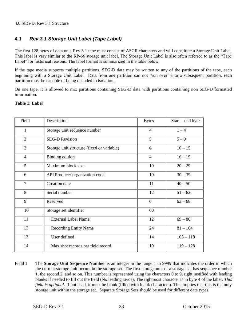
SEG-D Rev 3.1 33 October 2015
4.0 SEG-D, Rev 3.1 Structure
4.1 Rev 3.1 Storage Unit Label (Tape Label)
The first 128 bytes of data on a Rev 3.1 tape must consist of ASCII characters and will constitute a Storage Unit Label.
This label is very similar to the RP-66 storage unit label. The Storage Unit Label is also often referred to as the “Tape
Label” for historical reasons. The label format is summarized in the table below.
If the tape media supports multiple partitions, SEG-D data may be written to any of the partitions of the tape, each
beginning with a Storage Unit Label. Data from one partition can not “run over” into a subsequent partition, each
partition must be capable of being decoded in isolation.
On one tape, it is allowed to mix partitions containing SEG-D data with partitions containing non SEG-D formatted
information.
Table 1: Label
Field Description Bytes Start – end byte
1 Storage unit sequence number 4 1 – 4
2 SEG-D Revision 5 5 – 9
3 Storage unit structure (fixed or variable) 6 10 – 15
4 Binding edition 4 16 – 19
5 Maximum block size 10 20 – 29
6 API Producer organization code 10 30 – 39
7 Creation date 11 40 – 50
8 Serial number 12 51 – 62
9 Reserved 6 63 – 68
10 Storage set identifier 60
11 External Label Name 12 69 – 80
12 Recording Entity Name 24 81 – 104
13 User defined 14 105 – 118
14 Max shot records per field record 10 119 – 128
Field 1 The Storage Unit Sequence Number is an integer in the range 1 to 9999 that indicates the order in which
the current storage unit occurs in the storage set. The first storage unit of a storage set has sequence number
1, the second 2, and so on. This number is represented using the characters 0 to 9, right justified with leading
blanks if needed to fill out the field (No leading zeros). The rightmost character is in byte 4 of the label. This
field is optional. If not used, it must be blank (filled with blank characters). This implies that this is the only
storage unit within the storage set. Separate Storage Sets should be used for different data types.

SEG-D Rev 3.1 34 October 2015
Field 2 The SEG-D Revision field indicates which revision of SEG-D was used to record the data on this tape.
SD3.1 indicates that the data was recorded using SEG-D, Revision 3.1 (SD3.0 in previous revision) - This
field is required.
Field 3 Storage Unit Structure is a name indicating the record structure of the storage unit. This name is left
justified with trailing blanks if needed to fill out the field. The leftmost character is in byte 10 of the label.
For SEG-D, Rev 3 tapes, this field must contain “RECORD” or “FIXREC”. This field is required.
“RECORD” — Records may be of variable length, ranging up to the length specified in the Maximum block
size field of the storage unit label (if not zero). If the Maximum block size specified is zero, then records
may be of any length.
“FIXREC” — All records in the storage unit have the same length, namely that specified in the Maximum
block size field of the storage unit label. Although all storage units in the same storage set must have a
FIXREC structure, the maximum record length may be different in different storage units. When the
FIXREC option is used, then the maximum record length field shall not be 0 (zero).
Field 4 Binding edition is the character B in byte 16 of the label followed by a positive integer in the range 1 to 999
(no leading zeros), left justified with trailing blanks if needed to fill out the field. The integer value
corresponds to the edition of the Part 3 of the API, RP66 standard used to describe the physical binding of
the logical format to the storage unit. This field is required. The field should be set to ‘B2 ’ for SEG-D Rev
3.0.
Field 5 Maximum block size is an integer in the range of 0 to 4,294,967,295 (232
−1), indicating the maximum block
length for the storage unit, or 0 (zero) if undeclared. This number is represented using the characters 0 to 9,
right justified, with leading blanks if necessary to fill out the field (no leading zeros). The rightmost
character is byte 29 of the label. A valid value or 0 (zero) must be recorded. A value of 1 means byte stream
device (e.g. disk). It is highly recommended to indicate the maximum block length where possible, as this
will determine the size buffer needed to read the data, and will enable reading the data at a more optimal
speed (using multi-block read).
Field 6 Producer organization code is an integer in the range of 0 to 4,294,967,295 (232
−1) indicating the
organization code of the storage unit producer. This number is represented using the characters 0 to 9, right
justified, with leading blanks if necessary to fill out the field (NO leading zeros). The rightmost character is
byte 39 of the label. This field may be empty, i.e. may contain all blanks, in which case no storage unit
producer is specified (i.e. same as RP-66 V2).
Organization codes are assigned by Energistics, formerly the Petrotechnical Open Standards Consortium
(POSC), which maintains the current list of codes. Please refer to Appendix C for a list of the currently
assigned codes. To request a new organization code, contact:
Energistics
One Sugar Creek Center Blvd.
Suite 1075
Sugar Land, TX 77478 USA
+1 281 243-2121 telephone
+1 281 243-2132 fax
Field 7 Creation date is the earliest date that any current information was recorded on the storage unit. The date is
represented in the form dd-MMM-yyyy, where yyyy is the year (e.g. 1996), MMM is one of (JAN, FEB,
MAR, APR, MAY, JUN, JUL, AUG, SEP, OCT, NOV, DEC), and dd is the day of the month in the range 1
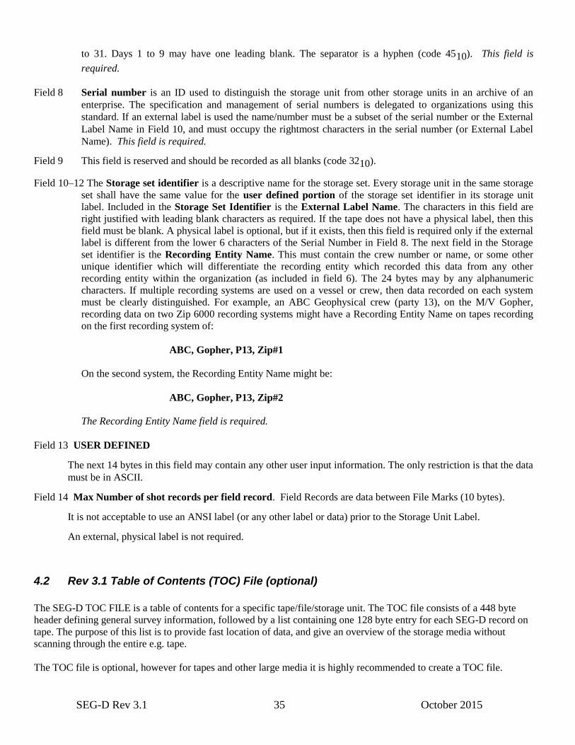
SEG-D Rev 3.1 35 October 2015
to 31. Days 1 to 9 may have one leading blank. The separator is a hyphen (code 4510). This field is
required.
Field 8 Serial number is an ID used to distinguish the storage unit from other storage units in an archive of an
enterprise. The specification and management of serial numbers is delegated to organizations using this
standard. If an external label is used the name/number must be a subset of the serial number or the External
Label Name in Field 10, and must occupy the rightmost characters in the serial number (or External Label
Name). This field is required.
Field 9 This field is reserved and should be recorded as all blanks (code 3210).
Field 10–12 The Storage set identifier is a descriptive name for the storage set. Every storage unit in the same storage
set shall have the same value for the user defined portion of the storage set identifier in its storage unit
label. Included in the Storage Set Identifier is the External Label Name. The characters in this field are
right justified with leading blank characters as required. If the tape does not have a physical label, then this
field must be blank. A physical label is optional, but if it exists, then this field is required only if the external
label is different from the lower 6 characters of the Serial Number in Field 8. The next field in the Storage
set identifier is the Recording Entity Name. This must contain the crew number or name, or some other
unique identifier which will differentiate the recording entity which recorded this data from any other
recording entity within the organization (as included in field 6). The 24 bytes may by any alphanumeric
characters. If multiple recording systems are used on a vessel or crew, then data recorded on each system
must be clearly distinguished. For example, an ABC Geophysical crew (party 13), on the M/V Gopher,
recording data on two Zip 6000 recording systems might have a Recording Entity Name on tapes recording
on the first recording system of:
ABC, Gopher, P13, Zip#1
On the second system, the Recording Entity Name might be:
ABC, Gopher, P13, Zip#2
The Recording Entity Name field is required.
Field 13 USER DEFINED
The next 14 bytes in this field may contain any other user input information. The only restriction is that the data
must be in ASCII.
Field 14 Max Number of shot records per field record. Field Records are data between File Marks (10 bytes).
It is not acceptable to use an ANSI label (or any other label or data) prior to the Storage Unit Label.
An external, physical label is not required.
4.2 Rev 3.1 Table of Contents (TOC) File (optional)
The SEG-D TOC FILE is a table of contents for a specific tape/file/storage unit. The TOC file consists of a 448 byte
header defining general survey information, followed by a list containing one 128 byte entry for each SEG-D record on
tape. The purpose of this list is to provide fast location of data, and give an overview of the storage media without
scanning through the entire e.g. tape.
The TOC file is optional, however for tapes and other large media it is highly recommended to create a TOC file.
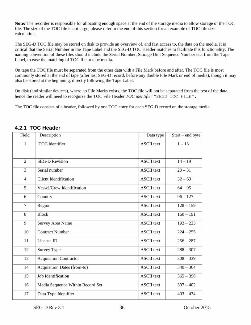
SEG-D Rev 3.1 36 October 2015
Note: The recorder is responsible for allocating enough space at the end of the storage media to allow storage of the TOC
file. The size of the TOC file is not large, please refer to the end of this section for an example of TOC file size
calculation.
The SEG-D TOC file may be stored on disk to provide an overview of, and fast access to, the data on the media. It is
critical that the Serial Number in the Tape Label and the SEG-D TOC Header matches to facilitate this functionality. The
naming convention of these files should include the Serial Number, Storage Unit Sequence Number etc. from the Tape
Label, to ease the matching of TOC file to tape media.
On tape the TOC file must be separated from the other data with a File Mark before and after. The TOC file is most
commonly stored at the end of tape (after last SEG-D record, before any double File Mark or end of media), though it may
also be stored at the beginning, directly following the Tape Label.
On disk (and similar devices), where no File Marks exists, the TOC file will not be separated from the rest of the data,
hence the reader will need to recognize the TOC File Header TOC identifier "SEGD TOC FILE".
The TOC file consists of a header, followed by one TOC entry for each SEG-D record on the storage media.
4.2.1 TOC Header
Field Description Data type Start – end byte
1 TOC identifier.
ASCII text 1 – 13
2 SEG-D Revision ASCII text 14 – 19
3 Serial number ASCII text 20 – 31
4 Client Identification ASCII text 32 – 63
5 Vessel/Crew Identification ASCII text 64 – 95
6 Country ASCII text 96 – 127
7 Region ASCII text 128 – 159
8 Block ASCII text 160 – 191
9 Survey Area Name ASCII text 192 – 223
10 Contract Number ASCII text 224 – 255
11 License ID ASCII text 256 – 287
12 Survey Type ASCII text 288 – 307
13 Acquisition Contractor ASCII text 308 – 339
14 Acquisition Dates (from-to) ASCII text 340 – 364
15 Job Identification ASCII text 365 – 396
16 Media Sequence Within Record Set ASCII text 397 – 402
17 Data Type Identifier ASCII text 403 – 434
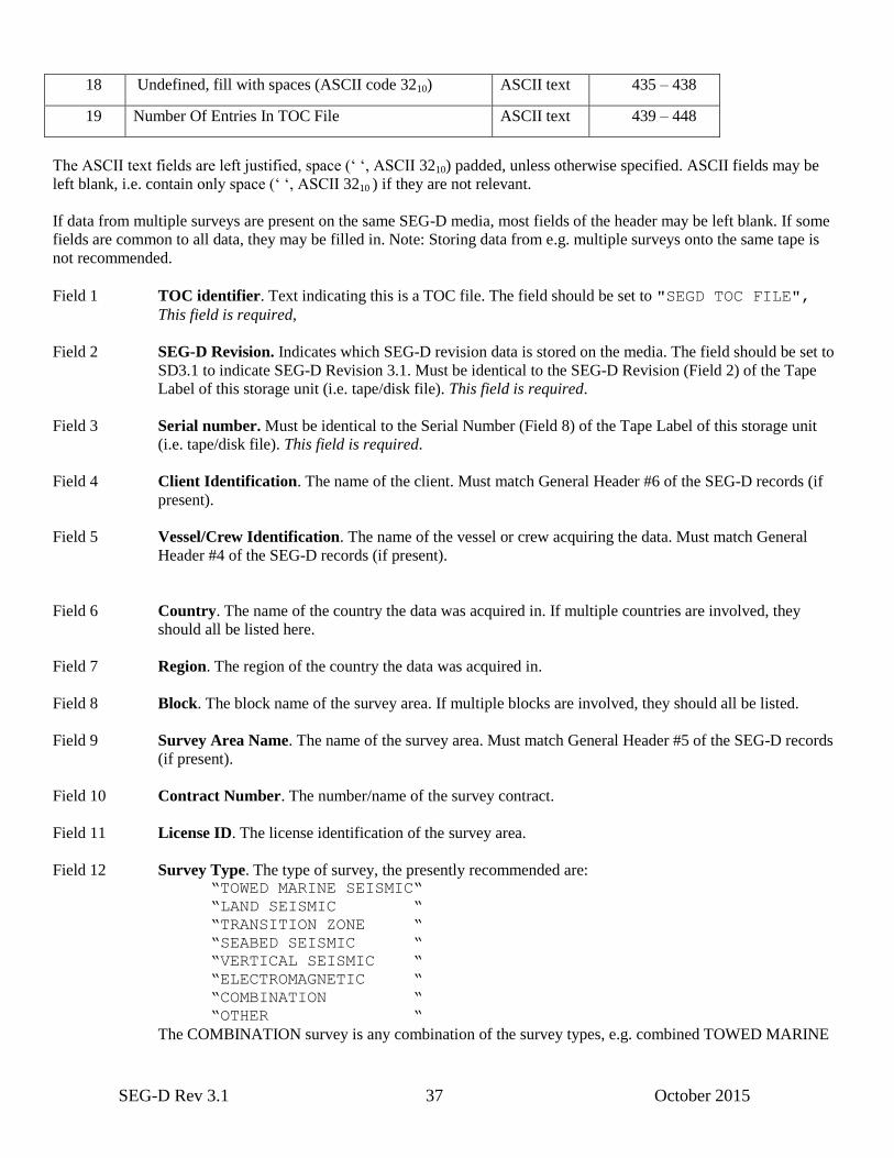
SEG-D Rev 3.1 37 October 2015
18 Undefined, fill with spaces (ASCII code 3210) ASCII text 435 – 438
19 Number Of Entries In TOC File ASCII text 439 – 448
The ASCII text fields are left justified, space (‘ ‘, ASCII 3210) padded, unless otherwise specified. ASCII fields may be
left blank, i.e. contain only space (‘ ‘, ASCII 3210 ) if they are not relevant.
If data from multiple surveys are present on the same SEG-D media, most fields of the header may be left blank. If some
fields are common to all data, they may be filled in. Note: Storing data from e.g. multiple surveys onto the same tape is
not recommended.
Field 1 TOC identifier. Text indicating this is a TOC file. The field should be set to "SEGD TOC FILE",
This field is required,
Field 2 SEG-D Revision. Indicates which SEG-D revision data is stored on the media. The field should be set to
SD3.1 to indicate SEG-D Revision 3.1. Must be identical to the SEG-D Revision (Field 2) of the Tape
Label of this storage unit (i.e. tape/disk file). This field is required.
Field 3 Serial number. Must be identical to the Serial Number (Field 8) of the Tape Label of this storage unit
(i.e. tape/disk file). This field is required.
Field 4 Client Identification. The name of the client. Must match General Header #6 of the SEG-D records (if
present).
Field 5 Vessel/Crew Identification. The name of the vessel or crew acquiring the data. Must match General
Header #4 of the SEG-D records (if present).
Field 6 Country. The name of the country the data was acquired in. If multiple countries are involved, they
should all be listed here.
Field 7 Region. The region of the country the data was acquired in.
Field 8 Block. The block name of the survey area. If multiple blocks are involved, they should all be listed.
Field 9 Survey Area Name. The name of the survey area. Must match General Header #5 of the SEG-D records
(if present).
Field 10 Contract Number. The number/name of the survey contract.
Field 11 License ID. The license identification of the survey area.
Field 12 Survey Type. The type of survey, the presently recommended are: “TOWED MARINE SEISMIC“
“LAND SEISMIC “
“TRANSITION ZONE “
“SEABED SEISMIC “
“VERTICAL SEISMIC “
“ELECTROMAGNETIC “
“COMBINATION “
“OTHER “
The COMBINATION survey is any combination of the survey types, e.g. combined TOWED MARINE
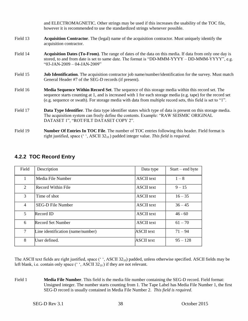
SEG-D Rev 3.1 38 October 2015
and ELECTROMAGNETIC. Other strings may be used if this increases the usability of the TOC file,
however it is recommended to use the standardized strings whenever possible.
Field 13 Acquisition Contractor. The (legal) name of the acquisition contractor. Must uniquely identify the
acquisition contractor.
Field 14 Acquisition Dates (To-From). The range of dates of the data on this media. If data from only one day is
stored, to and from date is set to same date. The format is “DD-MMM-YYYY – DD-MMM-YYYY”, e.g.
“03-JAN-2009 – 04-JAN-2009”
Field 15 Job Identification. The acquisition contractor job name/number/identification for the survey. Must match
General Header #7 of the SEG-D records (if present).
Field 16 Media Sequence Within Record Set. The sequence of this storage media within this record set. The
sequence starts counting at 1, and is increased with 1 for each storage media (e.g. tape) for the record set
(e.g. sequence or swath). For storage media with data from multiple record sets, this field is set to “1”.
Field 17 Data Type Identifier. The data type identifier states which type of data is present on this storage media.
The acquisition system can freely define the contents. Example: “RAW SEISMIC ORIGINAL
DATASET 1”, “ROT/FILT DATASET COPY 2”.
Field 19 Number Of Entries In TOC File. The number of TOC entries following this header. Field format is
right justified, space (‘ ‘, ASCII 3210 ) padded integer value. This field is required.
4.2.2 TOC Record Entry
Field Description Data type Start – end byte
1 Media File Number ASCII text 1 – 8
2 Record Within File ASCII text 9 – 15
3 Time of shot ASCII text 16 – 35
4 SEG-D File Number ASCII text 36 – 45
5 Record ID ASCII text 46 - 60
6 Record Set Number ASCII text 61 – 70
7 Line identification (name/number) ASCII text 71 – 94
8 User defined. ASCII text 95 – 128
The ASCII text fields are right justified, space (‘ ‘, ASCII 3210) padded, unless otherwise specified. ASCII fields may be
left blank, i.e. contain only space (‘ ‘, ASCII 3210 ) if they are not relevant.
Field 1 Media File Number. This field is the media file number containing the SEG-D record. Field format:
Unsigned integer. The number starts counting from 1. The Tape Label has Media File Number 1, the first
SEG-D record is usually contained in Media File Number 2. This field is required.
SEG-D Rev 3.1 39 October 2015
Field 2 Record Within File. Multiple SEG-D records may be stored within one single media file (though this is
not recommended for field tapes). Record Within File starts counting from 1, i.e. the first SEG-D record
has Record Within File = 1 (and starts at byte 0 of the media file). Field format: Unsigned integer. This
field is required.
Field 3 Time Of Shot. This field is identical to the Time Zero of the SEG-D record (General Header Block #3,
bytes 1–8), and matches the timestamp in General Header Block #1 (bytes 11–16). Field format: Signed
integer. This field is required.
Field 4 SEG-D File Number. The SEG-D file number as listed in the General Header of the SEG-D record
(bytes 1–2 of General Header Block #1, or bytes 1–3 of General Header Block #2). Field format:
Unsigned integer. This field is required.
Field 5 Record ID. The record ID identifies the record within the record set. Field format: Signed floating point
value, some examples: “4” “4.0” “4.000” “-4.0512”. This may be the shot point or source point number if
available, but can be any number that identify this record within the record set.
Field 6 Record set number. The record set this SEG-D record belongs to. Must be the same as bytes 21-22 of
General Header #2. Field format: Unsigned integer.
Field 7 Line identification (name/number). The line number or name of the line the record belongs to. For
surveys where both receiver and source line numbers exists, it is recommended to set this field to the
source line number whenever possible. Set to empty (all spaces, ASCII 3210) if not valid. Must match
General Header #8 Line Identification field of the SEG-D record (if present). Field is left justified space (‘
‘, ASCII 3210 ) padded ASCII string.
Field 8 User defined. 34 bytes of user defined ASCII text. The field can be freely utilized by the recorder, but the
contents must be ASCII text. Record as empty (fill with space (‘ ‘, ASCII 3210) if not used).
TOC file size calculation example:
Size of shot:
5000 channels, 10 seismic seconds (i.e. 10240 milliseconds) record length, SEG-D 8036 format (3 byte per
sample) and 2 millisecond sampling rate. All traces recorded for the full record time, each trace has five 32 byte
Trace Header Extension blocks. (For simplicity we ignore the SEG-D record header, it is assumed to be small
compared to the data).
5000 * (10240 / 2 * 3 + 5 * 32 + 20) = 77700000 bytes = 74.1 MB
Size of tape:
300 000 MB (or ~300 GB)
Size of table of contents file:
448 + 300000/74.1 * 128 = 507 kB (approximately)
The recorder of this dataset will need to leave 507 kilobytes of space at the end of a 300 GB tape for storing the
TOC file.
4.2.3 Using the TOC with SEG-D on disk

SEG-D Rev 3.1 40 October 2015
The Table of Contents is designed to aid in rapid access to data stored on tape and other sequential record-oriented media
where random access to arbitrary byte locations on the media is unavailable. For SEG-D datasets created as one huge
contiguous byte stream disk file, the TOC would be trivial and of quite modest utility, with just a list of TOC Record
entries showing the SEG-D File Numbers in that file, but providing no way of locating those records short of reading
through the disk file until the desired record is encountered (note that the reading is quite simple though as GeneralHeader
#3 contains size of record allowing fast jump to next record). For this reason, as well as to limit the loss of data should a
disk file be corrupted, we recommend that SEG-D data be created directly on disk in the following manner:
- The SEG-D Storage Unit Label and each Record should be written to a separate disk file.
- The naming convention of these files should include the numeric Media File Number from the TOC Record Entry field.
We also recommend the disk file name include the Record Set Number from that same TOC Record Entry and the Media
Sequence Within Record Set from the TOC Header prepended before the Media File Number.
For SEG-D records copied to disk from tape, the existing TOC is copied to a disk file of its own. In order for this copied
TOC to be immediately valid for the disk copy, we recommend the data be copied to disk in the following manner:
- Each individual tape file (which may include multiple SEG-D File Numbers) should be copied to a separate disk file. A
dummy SEG-D Storage Unit Label must be prepended before the data. It is recommended that the dummy label is based
on the tape Storage Unit Label, but modifications done such that it will not be confused with the real tape data. It is
however strongly recommended to include a reference to the original tape media in the dummy label, e.g. by utilizing the
“User defined” portion of the Storage Unit Label.
- The naming convention of these files should include the numeric Record Set Number, the Media Sequence Within
Record Set and Media File Number from the existing TOC.
For ease of listing and sorting, the numeric fields embedded in the file names should each be of a fixed length, with
leading zeros padded instead of blanks, so as to accommodate the largest possible value for that field. So, for example, if
we use the template FILE_[rsn]_[mseq]_[mfn].SGD for file names, the Record Set Number (rsn) should be 5 digits
long, the Media Sequence Within File (mseq) should be 6 digits long, and the Media File Number 8 digits long. This
results in a file name of 29 characters, quite manageable on all modern computer systems.
Note: There are a lot of other ways of storing SEG-D data on disk, for example storing each individual tape file as a disk
file in a filesystem directory. This is perfectly legal, and may be very useful for internal data storage, but it is not
considered proper SEG-D data as each disk file does not start with a Storage Unit Label and the data can not be treated
as a stream of bytes (each disk file must be read separately).
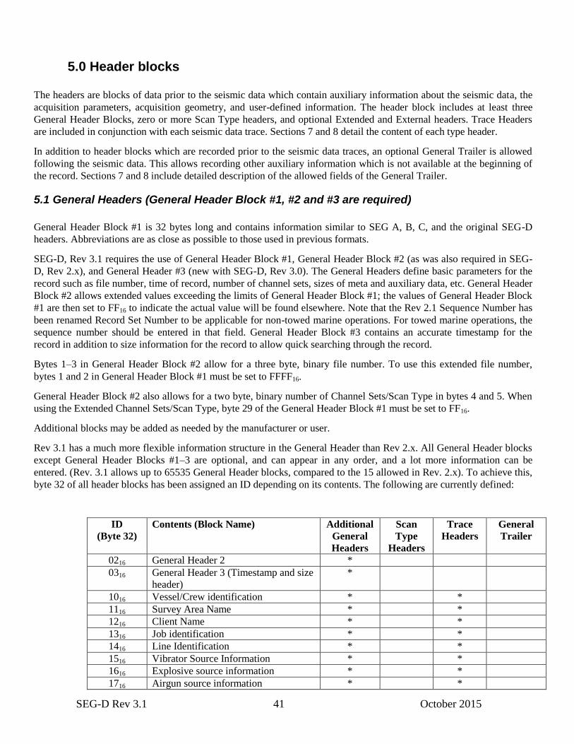
SEG-D Rev 3.1 41 October 2015
5.0 Header blocks
The headers are blocks of data prior to the seismic data which contain auxiliary information about the seismic data, the
acquisition parameters, acquisition geometry, and user-defined information. The header block includes at least three
General Header Blocks, zero or more Scan Type headers, and optional Extended and External headers. Trace Headers
are included in conjunction with each seismic data trace. Sections 7 and 8 detail the content of each type header.
In addition to header blocks which are recorded prior to the seismic data traces, an optional General Trailer is allowed
following the seismic data. This allows recording other auxiliary information which is not available at the beginning of
the record. Sections 7 and 8 include detailed description of the allowed fields of the General Trailer.
5.1 General Headers (General Header Block #1, #2 and #3 are required)
General Header Block #1 is 32 bytes long and contains information similar to SEG A, B, C, and the original SEG-D
headers. Abbreviations are as close as possible to those used in previous formats.
SEG-D, Rev 3.1 requires the use of General Header Block #1, General Header Block #2 (as was also required in SEG-
D, Rev 2.x), and General Header #3 (new with SEG-D, Rev 3.0). The General Headers define basic parameters for the
record such as file number, time of record, number of channel sets, sizes of meta and auxiliary data, etc. General Header
Block #2 allows extended values exceeding the limits of General Header Block #1; the values of General Header Block
#1 are then set to FF16 to indicate the actual value will be found elsewhere. Note that the Rev 2.1 Sequence Number has
been renamed Record Set Number to be applicable for non-towed marine operations. For towed marine operations, the
sequence number should be entered in that field. General Header Block #3 contains an accurate timestamp for the
record in addition to size information for the record to allow quick searching through the record.
Bytes 1–3 in General Header Block #2 allow for a three byte, binary file number. To use this extended file number,
bytes 1 and 2 in General Header Block #1 must be set to FFFF16.
General Header Block #2 also allows for a two byte, binary number of Channel Sets/Scan Type in bytes 4 and 5. When
using the Extended Channel Sets/Scan Type, byte 29 of the General Header Block #1 must be set to FF16.
Additional blocks may be added as needed by the manufacturer or user.
Rev 3.1 has a much more flexible information structure in the General Header than Rev 2.x. All General Header blocks
except General Header Blocks #1–3 are optional, and can appear in any order, and a lot more information can be
entered. (Rev. 3.1 allows up to 65535 General Header blocks, compared to the 15 allowed in Rev. 2.x). To achieve this,
byte 32 of all header blocks has been assigned an ID depending on its contents. The following are currently defined:
ID
(Byte 32)
Contents (Block Name) Additional
General
Headers
Scan
Type
Headers
Trace
Headers
General
Trailer
0216 General Header 2 *
0316 General Header 3 (Timestamp and size
header)
*
1016 Vessel/Crew identification * *
1116 Survey Area Name * *
1216 Client Name * *
1316 Job identification * *
1416 Line Identification * *
1516 Vibrator Source Information * *
1616 Explosive source information * *
1716 Airgun source information * *
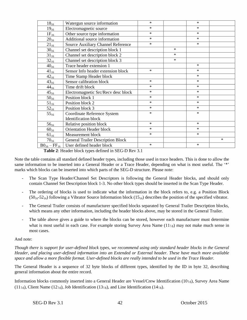
SEG-D Rev 3.1 42 October 2015
1816 Watergun source information * *
1916 Electromagnetic source * *
1F16 Other source type information * *
2016 Additional source information * *
2116 Source Auxiliary Channel Reference * *
3016 Channel set description block 1 *
3116 Channel set description block 2 *
3216 Channel set description block 3 *
4016 Trace header extension 1 *
4116 Sensor Info header extension block * *
4216 Time Stamp Header block *
4316 Sensor calibration block * *
4416 Time drift block * *
4516 Electromagnetic Src/Recv desc block * *
5016 Position block 1 * *
5116 Position block 2 * *
5216 Position block 3 * *
5516 Coordinate Reference System
Identification block
* *
5616 Relative position block * *
6016 Orientation Header block * *
6116 Measurement block * *
7016 General Trailer Description Block *
B016 – FF16 User defined header block * *
Table 2: Header block types defined in SEG-D Rev 3.1
Note the table contains all standard defined header types, including those used in trace headers. This is done to allow the
same information to be inserted into a General Header or a Trace Header, depending on what is most useful. The ‘*’
marks which blocks can be inserted into which parts of the SEG-D structure. Please note:
- The Scan Type Header/Channel Set Descriptors is following the General Header blocks, and should only
contain Channel Set Description block 1-3. No other block types should be inserted in the Scan Type Header.
- The ordering of blocks is used to indicate what the information in the block refers to, e.g. a Position Block
(5016-5216) following a Vibrator Source Information block (1516) describes the position of the specified vibrator.
- The General Trailer consists of manufacturer specified blocks separated by General Trailer Description blocks,
which means any other information, including the header blocks above, may be stored in the General Trailer.
- The table above gives a guide to where the blocks can be stored, however each manufacturer must determine
what is most useful in each case. For example storing Survey Area Name (1116) may not make much sense in
most cases.
And note:
Though there is support for user-defined block types, we recommend using only standard header blocks in the General
Header, and placing user-defined information into an Extended or External header. These have much more available
space and allow a more flexible format. User-defined blocks are really intended to be used in the Trace Header.
The General Header is a sequence of 32 byte blocks of different types, identified by the ID in byte 32, describing
general information about the entire record.
Information blocks commonly inserted into a General Header are Vessel/Crew Identification (1016), Survey Area Name
(1116), Client Name (1216), Job Identification (1316), and Line Identification (1416).

SEG-D Rev 3.1 43 October 2015
If the record is related to a single source event (shot), we recommend inserting information regarding the source (IDs
1516–1916 or 1F16 depending on source type) into a General Header. If multiple source events occur in the record, e.g.
in land slip-sweep operations, storing the source information in the relevant auxiliary source trace headers can be done.
To be able to associate information to the correct source (in General Header or Trace Header), the header blocks should
be ordered such that all information regarding one source is grouped together, followed by information related to the
next source etc. This is crucial when dealing with blocks not containing the Source ID like the Position Block. This can
schematically be summarized like this:
0..r
0..1 Source
Description
0..q
0..1 Additional
Source Info
0..n Source Aux
Channel Reference
0..m Position
Block
0..p Any other blocks
related to the source
For more information regarding the use of Source Description blocks, please refer to example E.7.
Note:
Source information (e.g. Additional Source Info or Source Aux Channel Reference) may appear in Trace Headers
without a Source Description block in front, however there must then be a Source Description block for that source in
General Header. It is not allowed to store source information in General Header without a Source Description block.
5.2 Scan Type Headers
The Scan Type Header is used to describe the information about the recorded channels (filters, sampling intervals,
sample skew, etc.). The Scan Type Header is composed of one or more channel set descriptors followed by skew
information. The channel set descriptors must appear in the same order as their respective channel sets will appear
within a base scan interval. A channel set, which is part of a scan type, is defined as a group of channels all recorded
with identical recording parameters. One or more channel sets can be recorded concurrently within one scan type. In
addition, there can be multiple scan types to permit dynamic scan type changes during the record (e.g., 12 channels at
1/2 ms switched at about 1 second to 48 channels at 2 ms). Where there are dynamic changes, Scan Type Header #1
describes the first part of the record, Scan Type Header #2 the second part, etc. Within the Scan Type Header, each
channel set descriptor is composed of a 96 byte field, and up to 65535 channel set descriptors may be present. In
addition, up to 99 scan type headers may be utilized in a record.
Following the channel set descriptors of a scan type are a number of 32 byte fields (SK, specified in byte 30 of General
Header #1) that specify sample skew. Sample skew (SS) is recorded in a single byte for each sample of each subscan of
each channel set, in the same order as the samples are recorded in the scan. Each byte represents a fractional part of the
base scan interval (Byte 23 of General Header #1). The resolution is 1/256 of this interval. For instance, if the base scan
interval is 2 msec, the least significant bit in the sample skew byte is 1/256 of 2 msec or 7.8125 microseconds.

SEG-D Rev 3.1 44 October 2015
A channel set is a group of channels that:
a) Use identical recording parameters. This includes the same record length and sampling interval.
b) Use identical processing parameters, including the same filter selection and array forming parameters.
c) Originates from the same streamer cable for marine data. The streamer cable number for each channel set is
included in the channel set descriptor byte 31.
d) Consists of channels with the same group spacing. For example, if one streamer has short group spacing close to
the boat and longer group spacing at long offsets, the data from the streamer would be recorded as two channel
sets. The first channel in each channel set will start with trace number one.
The following is a list of ground rules for the scan type header:
1. The order in which channel sets are described in the header will be the same as the order in which the data are
recorded for each channel set.
2. In a Scan Type Header containing multiple channel set descriptors with different sampling intervals, each channel
set descriptor will appear only once in each scan type header. Within the data block, however, shorter sampling
interval data are recorded more frequently.
3. In the case of multiple scan type records, such as the dynamically switched sampling interval case, each scan type
will contain the same number of channel sets. Any unused channel sets needed in a scan type must be so indicated
by setting bytes 21 to 23 (channels per channel set) to zero in the channel set descriptor.
4. In multiple scan type records, the number of bytes per base scan interval must remain a constant for all scan types
recorded.
5. Channels within the same Channel Set must now have the same number of Trace Header Extensions. Since all
traces within a Channel Set will contain the same number of Trace Header Extensions, the number of Trace
Header Extensions will be indicated in the Channel Set Descriptor. Byte 28 of the Channel Set Descriptor
contains the number of Trace Extension Headers in the channel set. This must match the byte 10 of the Demux
Trace Header of traces in the channel set. Each trace is hence limited to a maximum of 255 Trace Header
Extension blocks.
6. The length of each trace within a Channel Set is restricted to be the same value. This limitation and the restriction
of the number of Trace Header Extensions to the same number within a Channel Set will result in each trace
within a Channel Set being recorded with the same number of bytes.
5.3 Demux Trace Header (required)
The Demux Trace Header length is 20 bytes and is an identifier that precedes each channel’s data. The trace header and
the trace data are recorded as one block of data. A trace is restricted to one channel of data from one channel set of one
scan type. Some of the information in the trace header is taken directly from the general header and the scan type
header.
Bytes 7, 8, and 9 comprise the timing word that would accompany the first sample if these data were written in
multiplex format. To obtain the exact sample time, the actual sample skew time (Byte 11 multiplied by the base scan
interval) must be added to the time recorded in Bytes 7, 8, and 9.
The timing word is in milliseconds and has the following bit weight assignments:
Timing word
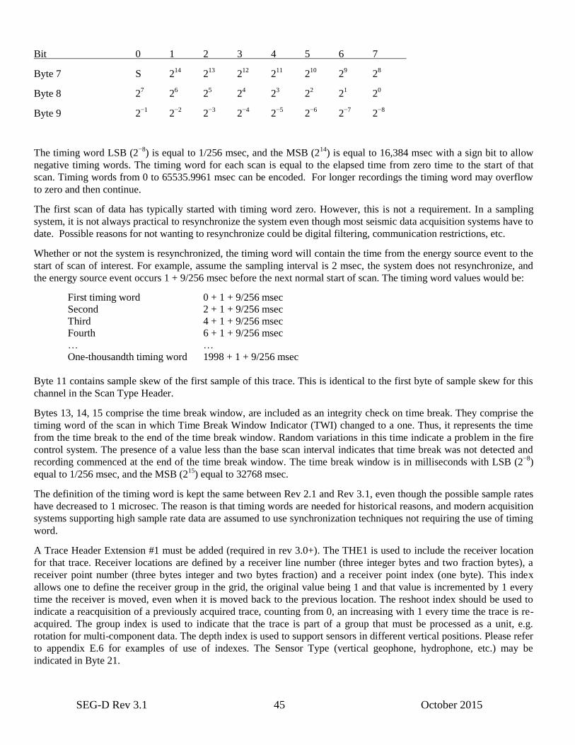
SEG-D Rev 3.1 45 October 2015
Bit 0 1 2 3 4 5 6 7
Byte 7 S 214
213
212
211
210
29 2
8
Byte 8 27 2
6 2
5 2
4 2
3 2
2 2
1 2
0
Byte 9 2−1
2−2
2−3
2−4
2−5
2−6
2−7
2−8
The timing word LSB (2−8
) is equal to 1/256 msec, and the MSB (214
) is equal to 16,384 msec with a sign bit to allow
negative timing words. The timing word for each scan is equal to the elapsed time from zero time to the start of that
scan. Timing words from 0 to 65535.9961 msec can be encoded. For longer recordings the timing word may overflow
to zero and then continue.
The first scan of data has typically started with timing word zero. However, this is not a requirement. In a sampling
system, it is not always practical to resynchronize the system even though most seismic data acquisition systems have to
date. Possible reasons for not wanting to resynchronize could be digital filtering, communication restrictions, etc.
Whether or not the system is resynchronized, the timing word will contain the time from the energy source event to the
start of scan of interest. For example, assume the sampling interval is 2 msec, the system does not resynchronize, and
the energy source event occurs 1 + 9/256 msec before the next normal start of scan. The timing word values would be:
First timing word 0 + 1 + 9/256 msec
Second 2 + 1 + 9/256 msec
Third 4 + 1 + 9/256 msec
Fourth 6 + 1 + 9/256 msec
… …
One-thousandth timing word 1998 + 1 + 9/256 msec
Byte 11 contains sample skew of the first sample of this trace. This is identical to the first byte of sample skew for this
channel in the Scan Type Header.
Bytes 13, 14, 15 comprise the time break window, are included as an integrity check on time break. They comprise the
timing word of the scan in which Time Break Window Indicator (TWI) changed to a one. Thus, it represents the time
from the time break to the end of the time break window. Random variations in this time indicate a problem in the fire
control system. The presence of a value less than the base scan interval indicates that time break was not detected and
recording commenced at the end of the time break window. The time break window is in milliseconds with LSB (2−8
)
equal to 1/256 msec, and the MSB (215
) equal to 32768 msec.
The definition of the timing word is kept the same between Rev 2.1 and Rev 3.1, even though the possible sample rates
have decreased to 1 microsec. The reason is that timing words are needed for historical reasons, and modern acquisition
systems supporting high sample rate data are assumed to use synchronization techniques not requiring the use of timing
word.
A Trace Header Extension #1 must be added (required in rev 3.0+). The THE1 is used to include the receiver location
for that trace. Receiver locations are defined by a receiver line number (three integer bytes and two fraction bytes), a
receiver point number (three bytes integer and two bytes fraction) and a receiver point index (one byte). This index
allows one to define the receiver group in the grid, the original value being 1 and that value is incremented by 1 every
time the receiver is moved, even when it is moved back to the previous location. The reshoot index should be used to
indicate a reacquisition of a previously acquired trace, counting from 0, an increasing with 1 every time the trace is re-
acquired. The group index is used to indicate that the trace is part of a group that must be processed as a unit, e.g.
rotation for multi-component data. The depth index is used to support sensors in different vertical positions. Please refer
to appendix E.6 for examples of use of indexes. The Sensor Type (vertical geophone, hydrophone, etc.) may be
indicated in Byte 21.

SEG-D Rev 3.1 46 October 2015
Additional trace header blocks (e.g. source information, positions, orientation blocks, or manufacturer defined blocks)
may be added as needed by the manufacturer or user. The maximum number of Trace Header Extensions is limited to
255.
A larger number of samples per trace may be recorded using bytes 25–28 of the first Trace Header Extension.
5.4 Extended Header (optional)
The Extended Header provides additional areas to be used by equipment manufacturers to interface directly with their
equipment. Since the nature of this data will depend heavily on the equipment and processes being applied, it will be the
responsibility of the equipment manufacturer to establish a format and document this area. Byte 31 of General Header
Block #1 contains the number of 32 byte fields in the Extended Header. If more than 99 Extended Header blocks are
used, then General Header Block #1, byte 31 is set to FF16 and bytes 6 to 8 in the General Header Block #2 indicate the
number of Extended Header Blocks.
5.5 External Header (optional)
The External Header provides a means of recording special user-desired information in the header block. This data
format will be defined and documented by the end user. The means of putting this information into the header has
usually been provided by the equipment manufacturer. Byte 32 of General Header Block #1 contains the number of 32
byte fields in the external header. If more than 99 External Header blocks are used, then General Header Block #1, Byte
32 is set to FF16 and Bytes 28 to 30 of General Header Block #2 indicates the number of External Header blocks.
5.6 General Trailer (optional)
Following the seismic data, a General Trailer may be recorded. This provides for recording auxiliary system and
positioning related data. The addition of the trailer will allow the accumulation of system faults, data QC information,
real-time position, and timing information on the same record and contiguous with the shotpoint to which it relates. By
recording this data after all of the other data, additional time is provided for collecting the data and transferring it to the
recording system. The General Trailer consists of a set of blocks consisting of a short header followed by a number of
data blocks. All information in the General Trailer is optional, and each block may be formatted as desired by the
manufacturer or user. The number of General Trailer blocks is indicated in bytes 13 to 16 of General Header Block #2.
To aid with the transfer of information between acquisition and processing, a few types of trailer blocks have been
defined:
1. Edits
2. Position data backup
3. Text comments
4. Observer log
We recommended using these standard formats when inserting this type of information in the trailer.
Note: All types of trailer records are optional.

SEG-D Rev 3.1 47 October 2015
5.6.1 Edit (SEG-D Trace Edit v1.0)
Block Type (byte 1) is set to 0116, ASCII/binary (byte 2) set to 0216 and Description (byte 9–24) set to
"TRACE EDIT v1.0 ".
The edits trailer allows the recorder to modify the trace information provided by the trace header in the record. This is
typically used to indicate problems with certain traces. Edits trailer blocks are typically generated post acquisition, during
the QC and processing stages. SEG-D Rev 3 allows multiple Edit trailer blocks to be defined. The information in later
Edit blocks overrides information in earlier blocks.
The format presented here is similar to the one described in [SEG ADS Trace Edit, Norris, Hares, Faichney, 2001, SEG-
UKOOA Ancillary Data Standard - ADS Trace Edit: Geophysics, 66, no. 06, 2040–2054], though some
modifications/simplifications have been done. The SEG ADS Trace Edit format is very flexible, and some adaptation
must be done to make it fit the SEG-D record structure. In addition, the format of some fields had to be more strictly
defined to enable automatic parsing of the format.
It is recommended that the recording system creates Edit records to indicate which traces are bad, even though this is also
indicated in the trace headers. This will give a quick overview of the shot without the need for scanning through all the
data, and will simplify importing of data into processing/QC systems.
Multiple Edit records may exist. The latter will override prior definitions.
The edit format is ASCII, to ease human readability.
The format consists of multiple lines, each line terminated with a newline terminator consisting of a Line Feed ('\n', 0A16)
or Carriage Return/Line Feed ("\r\n", 0D0A16).
From here on, <LF> is used to indicate newline, <space> to indicate the space character (2016).
Each line (record) consists of a record description letter followed by space (2016), then some ASCII text, and terminated
by a linefeed.
<Record function><space>ASCII text><LF>
The Edit block is padded with <space> until a multiple of 32 byte is reached.
Class Record Function
Character
Description
Header V SEG-D Trace Edit version (required)
Header C Comment
Header S Timestamp, UTC (required)
Header W
System/person to generate this edit
(required)
Header A Attribute definition and range (at least one
A record is required)
Header P Parameters for attribute, if one line is not
enough to describe the attribute (optional)
Header H Header, description of a test (required)
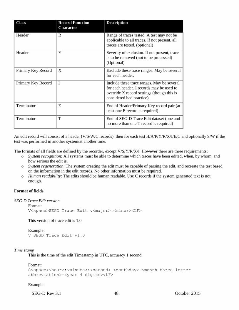
SEG-D Rev 3.1 48 October 2015
Class Record Function
Character
Description
Header R Range of traces tested. A test may not be
applicable to all traces. If not present, all
traces are tested. (optional)
Header Y Severity of exclusion. If not present, trace
is to be removed (not to be processed)
(Optional)
Primary Key Record X Exclude these trace ranges. May be several
for each header.
Primary Key Record I Include these trace ranges. May be several
for each header. I records may be used to
override X record settings (though this is
considered bad practice).
Terminator E End of Header/Primary Key record pair (at
least one E record is required)
Terminator T End of SEG-D Trace Edit dataset (one and
no more than one T record is required)
An edit record will consist of a header (V/S/W/C records), then for each test H/A/P/Y/R/X/I/E/C and optionally S/W if the
test was performed in another system/at another time.
The formats of all fields are defined by the recorder, except V/S/Y/R/X/I. However there are three requirements:
o System recognition: All systems must be able to determine which traces have been edited, when, by whom, and
how serious the edit is.
o System regeneration: The system creating the edit must be capable of parsing the edit, and recreate the test based
on the information in the edit records. No other information must be required.
o Human readability: The edits should be human readable. Use C records if the system generated text is not
enough.
Format of fields
SEG-D Trace Edit version
Format: V<space>SEGD Trace Edit v<major>.<minor><LF>
This version of trace edit is 1.0.
Example: V SEGD Trace Edit v1.0
Time stamp
This is the time of the edit Timestamp in UTC, accuracy 1 second.
Format: S<space><hour>:<minute>:<second> <monthday>-<month three letter
abbreviation>-<year 4 digits><LF>
Example:

SEG-D Rev 3.1 49 October 2015
S 13:35:00 23-MAR-2007
Severity of exclusion
What to do with the trace failing the test described in the A record. Y<space><severity><LF>
The following severities exist:
o EXCLUDE - The traces listed in X record should be excluded from further processing (default)
o WARNING - The traces listed in X records are suspicious, and further investigation is recommended.
Example: Y WARNING
Y EXCLUDE
Trace range definition
Used to define ranges of traces to test (R), include (I) or exclude (X).
Format:
<record letter><space><scanset NUMBER LIST;<channelset NUMBER LIST>;<trace
NUMBER LIST><LF>
NUMBER LIST is a comma separated list of numbers, or ranges. For example 1,4,10–14 means numbers 1, 4,
and 10 through 14.
Example: R 1-1,5-14,1-558
X 1-1,5-14,1-5
I 1-1,8-11,5-5
The ranges checked are traces 1–558 in channel sets 5–14 (e.g. the seismic channel sets for a 10 streamer vessel).
X record states traces 1–5 on all streamers fails the test (e.g. due to noise), but I record overrides, and indicates
channel 5 in channel set 8–11 passed.
See Appendix E.7 for a complete example of a Trace Edit v1.0 block.
5.6.2 Position data backup
Trailer block used as a backup of position related information. The contents are defined by the following table:
Contents Block type ASCII/
binary
Description
P1 Processed position data 2016 0216 (ASCII) “P1 FILE FORMAT ”
P2 Raw positioning data 2116 0216 (ASCII) “P2 FILE FORMAT ”
P3 Land survey field data 2216 0216 (ASCII) “P3 FILE Format ”
P5 Pipeline positioning data 2316 0216 (ASCII) “P5 FILE FORMAT ”
P6 3D seismic bin grid data 2416 0216 (ASCII) “P6 FILE FORMAT ”
P7 Well deviation data 2516 0216 (ASCII) “P7 FILE FORMAT ”
SPS Shell Processing Support data 2616 0216 (ASCII) “SPS FILE FORMAT ”
SEG-Y Extended Textual Stanza 2716 0216 (ASCII) “SEGY TEXT STANZA”
A whole file is added in a trailer block as described above. If multiple files need backing up, several trailer blocks may be
added.
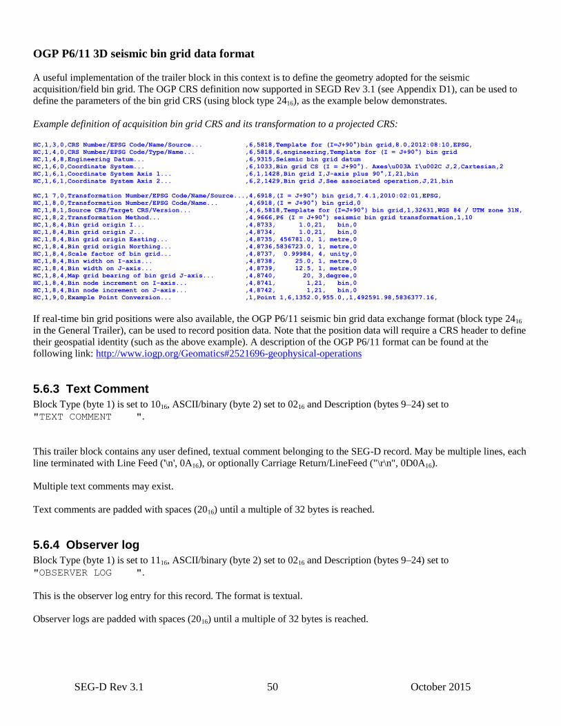
SEG-D Rev 3.1 50 October 2015
OGP P6/11 3D seismic bin grid data format
A useful implementation of the trailer block in this context is to define the geometry adopted for the seismic
acquisition/field bin grid. The OGP CRS definition now supported in SEGD Rev 3.1 (see Appendix D1), can be used to
define the parameters of the bin grid CRS (using block type 2416), as the example below demonstrates.
Example definition of acquisition bin grid CRS and its transformation to a projected CRS:
HC,1,3,0,CRS Number/EPSG Code/Name/Source... ,6,5818,Template for (I=J+90°)bin grid,8.0,2012:08:10,EPSG,
HC,1,4,0,CRS Number/EPSG Code/Type/Name... ,6,5818,6,engineering,Template for (I = J+90°) bin grid
HC,1,4,8,Engineering Datum... ,6,9315,Seismic bin grid datum
HC,1,6,0,Coordinate System... ,6,1033,Bin grid CS (I = J+90°). Axes\u003A I\u002C J,2,Cartesian,2
HC,1,6,1,Coordinate System Axis 1... ,6,1,1428,Bin grid I,J-axis plus 90°,I,21,bin
HC,1,6,1,Coordinate System Axis 2... ,6,2,1429,Bin grid J,See associated operation,J,21,bin
HC,1 7,0,Transformation Number/EPSG Code/Name/Source...,4,6918,(I = J+90°) bin grid,7.4.1,2010:02:01,EPSG,
HC,1,8,0,Transformation Number/EPSG Code/Name... ,4,6918,(I = J+90°) bin grid,0
HC,1,8,1,Source CRS/Target CRS/Version... ,4,6,5818,Template for (I=J+90°) bin grid,1,32631,WGS 84 / UTM zone 31N,
HC,1,8,2,Transformation Method... ,4,9666,P6 (I = J+90°) seismic bin grid transformation,1,10
HC,1,8,4,Bin grid origin I... ,4,8733, 1.0,21, bin,0
HC,1,8,4,Bin grid origin J... ,4,8734, 1.0,21, bin,0
HC,1,8,4,Bin grid origin Easting... ,4,8735, 456781.0, 1, metre,0
HC,1,8,4,Bin grid origin Northing... ,4,8736,5836723.0, 1, metre,0
HC,1,8,4,Scale factor of bin grid... ,4,8737, 0.99984, 4, unity,0
HC,1,8,4,Bin width on I-axis... ,4,8738, 25.0, 1, metre,0
HC,1,8,4,Bin width on J-axis... ,4,8739, 12.5, 1, metre,0
HC,1,8,4,Map grid bearing of bin grid J-axis... ,4,8740, 20, 3,degree,0
HC,1,8,4,Bin node increment on I-axis... ,4,8741, 1,21, bin,0
HC,1,8,4,Bin node increment on J-axis... ,4,8742, 1,21, bin,0
HC,1,9,0,Example Point Conversion... ,1,Point 1,6,1352.0,955.0,,1,492591.98,5836377.16,
If real-time bin grid positions were also available, the OGP P6/11 seismic bin grid data exchange format (block type 2416
in the General Trailer), can be used to record position data. Note that the position data will require a CRS header to define
their geospatial identity (such as the above example). A description of the OGP P6/11 format can be found at the
following link: http://www.iogp.org/Geomatics#2521696-geophysical-operations
5.6.3 Text Comment
Block Type (byte 1) is set to 1016, ASCII/binary (byte 2) set to 0216 and Description (bytes 9–24) set to
"TEXT COMMENT ".
This trailer block contains any user defined, textual comment belonging to the SEG-D record. May be multiple lines, each
line terminated with Line Feed ('\n', 0A16), or optionally Carriage Return/LineFeed ("\r\n", 0D0A16).
Multiple text comments may exist.
Text comments are padded with spaces (2016) until a multiple of 32 bytes is reached.
5.6.4 Observer log
Block Type (byte 1) is set to 1116, ASCII/binary (byte 2) set to 0216 and Description (bytes 9–24) set to
"OBSERVER LOG ".
This is the observer log entry for this record. The format is textual.
Observer logs are padded with spaces (2016) until a multiple of 32 bytes is reached.
SEG-D Rev 3.1 51 October 2015
5.6.5 User defined
The contents of the user defined block is completely left to the recording system, however the size must be a multiple of
32 bytes. The format is textual or binary as defined by the ASCII/binary flag in the description block. Byte 1 should be set
to a value between A016 and FF16.
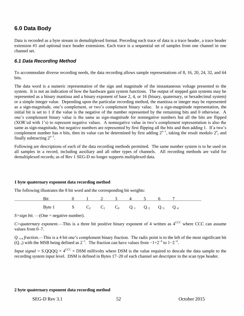
SEG-D Rev 3.1 52 October 2015
6.0 Data Body
Data is recorded as a byte stream in demultiplexed format. Preceding each trace of data is a trace header, a trace header
extension #1 and optional trace header extensions. Each trace is a sequential set of samples from one channel in one
channel set.
6.1 Data Recording Method
To accommodate diverse recording needs, the data recording allows sample representations of 8, 16, 20, 24, 32, and 64
bits.
The data word is a numeric representation of the sign and magnitude of the instantaneous voltage presented to the
system. It is not an indication of how the hardware gain system functions. The output of stepped gain systems may be
represented as a binary mantissa and a binary exponent of base 2, 4, or 16 (binary, quaternary, or hexadecimal system)
or a simple integer value. Depending upon the particular recording method, the mantissa or integer may be represented
as a sign-magnitude, one’s complement, or two’s complement binary value. In a sign-magnitude representation, the
initial bit is set to 1 if the value is the negative of the number represented by the remaining bits and 0 otherwise. A
one’s complement binary value is the same as sign-magnitude for nonnegative numbers but all the bits are flipped
(XOR’ed with 1’s) to represent negative values. A nonnegative value in two’s complement representation is also the
same as sign-magnitude, but negative numbers are represented by first flipping all the bits and then adding 1. If a two’s
complement number has n bits, then its value can be determined by first adding 2n−1
, taking the result modulo 2n, and
finally subtracting 2n−1
.
Following are descriptions of each of the data recording methods permitted. The same number system is to be used on
all samples in a record, including auxiliary and all other types of channels. All recording methods are valid for
demultiplexed records; as of Rev 1 SEG-D no longer supports multiplexed data.
1 byte quaternary exponent data recording method
The following illustrates the 8 bit word and the corresponding bit weights:
Bit 0 1 2 3 4 5 6 7
Byte 1 S C2 C1 C0 Q−1 Q−2 Q−3 Q−4
S=sign bit. —(One = negative number).
C=quaternary exponent.—This is a three bit positive binary exponent of 4 written as 4CCC
where CCC can assume
values from 0–7.
Q−1-4 fraction.—This is a 4 bit one’s complement binary fraction. The radix point is to the left of the most significant bit
(Q−1) with the MSB being defined as 2−1
. The fraction can have values from −1+2−4
to 1−2−4
.
Input signal = S.QQQQ × 4CCC
× DSM millivolts where DSM is the value required to descale the data sample to the
recording system input level. DSM is defined in Bytes 17–20 of each channel set descriptor in the scan type header.
2 byte quaternary exponent data recording method

SEG-D Rev 3.1 53 October 2015
The following illustrates the 16-bit word and the corresponding bit weights:
Bit 0 1 2 3 4 5 6 7
Byte 1 S C2 C1 C0 Q−1 Q−2 Q−3 Q−4
Byte 2 Q−5 Q−6 Q−7 Q−8 Q−9 Q−10 Q−11 Q−12
S=sign bit.—(One = negative number).
C=quaternary exponent.—This is a three bit positive binary exponent of 4 written as 4CCC
where CCC can assume
values from 0–7.
Q−1-12 fraction.—This is a 12 bit one’s complement binary fraction. The radix point is to the left of the most significant
bit (Q−1) with the MSB being defined as 2−1
. The fraction can have values from −1 + 2−12
to 1 − 2−12
.
Input signal = S.QQQQ,QQQQ,QQQQ × 4CCC
× DSM millivolts where DSM is the value required to descale the data
sample to the recording system input level. DSM is defined in Bytes 17–20 of each channel set descriptor in the scan
type header.
2½ byte binary exponent data recording method—demultiplexed
The following illustrates the 20 bit word and the corresponding bit weights:
Bit 0 1 2 3 4 5 6 7
Byte 1 C3 C2 C1 C0 C3 C2 C1 C0 Exponents for
Byte 2 C3 C2 C1 C0 C3 C2 C1 C0 samples 1 thru 4†
Byte 3 S Q−1 Q−2 Q−3 Q−4 Q−5 Q−6 Q−7 Sample 1
Byte 4 Q−8 Q−9 Q−10 Q−11 Q−12 Q−13 Q−14 Q−15
Byte 5 S Q−1 Q−2 Q−3 Q−4 Q−5 Q−6 Q−7 Sample 2
Byte 6 Q−8 Q−9 Q−10 Q−11 Q−12 Q−13 Q−14 Q−15
Byte 7 S Q−1 Q−2 Q−3 Q−4 Q−5 Q−6 Q−7 Sample 3
Byte 8 Q−8 Q−9 Q−10 Q−11 Q−12 Q−13 Q−14 Q−15
Byte 9 S Q−1 Q−2 Q−3 Q−4 Q−5 Q−6 Q−7 Sample 4
Byte 10 Q−8 Q−9 Q−10 Q−11 Q−12 Q−13 Q−14 Q−15
†Bytes 1 and 2 contain the exponents for the following four samples of the channel. The sample numbers are relative
and are only to denote position in the four sample group.
S=sign bit—(One = negative number).
C=binary exponent—This is a 4 bit positive binary exponent of 2 written as 2CCCC
where CCCC can assume values of
0–15. The four exponents are in sample order for the four samples starting with the first sample in bits 0–3 of Byte 1.
Q−1-15 fraction—This is a 15 bit one’s complement binary fraction. The radix point is to the left of the most significant
bit (Q−1) with the MSB being defined as 2−1
. The sign and fraction can assume values from 1 – 2−15
to –1 + 2−15
.
Input signal=S.QQQ,QQQQ,QQQQ,QQQQ × 2CCCC
× DSM millivolts where DSM is the value required to descale the
data word to the recording system input level. DSM is defined in Bytes 17–20 of each of the corresponding channel set
descriptors in the scan type header.
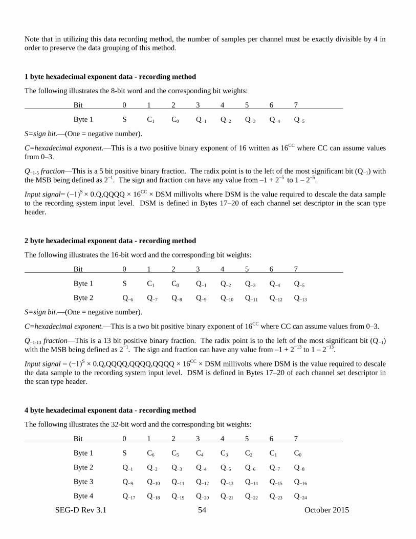
SEG-D Rev 3.1 54 October 2015
Note that in utilizing this data recording method, the number of samples per channel must be exactly divisible by 4 in
order to preserve the data grouping of this method.
1 byte hexadecimal exponent data - recording method
The following illustrates the 8-bit word and the corresponding bit weights:
Bit 0 1 2 3 4 5 6 7
Byte 1 S C1 C0 Q−1 Q−2 Q−3 Q−4 Q−5
S=sign bit.—(One = negative number).
C=hexadecimal exponent.—This is a two positive binary exponent of 16 written as 16CC
where CC can assume values
from 0–3.
Q−1-5 fraction—This is a 5 bit positive binary fraction. The radix point is to the left of the most significant bit (Q−1) with
the MSB being defined as 2−1
. The sign and fraction can have any value from –1 + 2−5
to 1 – 2−5
.
Input signal= (−1)S
× 0.Q,QQQQ × 16CC
× DSM millivolts where DSM is the value required to descale the data sample
to the recording system input level. DSM is defined in Bytes 17–20 of each channel set descriptor in the scan type
header.
2 byte hexadecimal exponent data - recording method
The following illustrates the 16-bit word and the corresponding bit weights:
Bit 0 1 2 3 4 5 6 7
Byte 1 S C1 C0 Q−1 Q−2 Q−3 Q−4 Q−5
Byte 2 Q−6 Q−7 Q−8 Q−9 Q−10 Q−11 Q−12 Q−13
S=sign bit.—(One = negative number).
C=hexadecimal exponent.—This is a two bit positive binary exponent of 16CC
where CC can assume values from 0–3.
Q−1-13 fraction—This is a 13 bit positive binary fraction. The radix point is to the left of the most significant bit (Q−1)
with the MSB being defined as 2−1
. The sign and fraction can have any value from –1 + 2−13
to 1 – 2−13
.
Input signal = (−1)S × 0.Q,QQQQ,QQQQ,QQQQ × 16
CC × DSM millivolts where DSM is the value required to descale
the data sample to the recording system input level. DSM is defined in Bytes 17–20 of each channel set descriptor in
the scan type header.
4 byte hexadecimal exponent data - recording method
The following illustrates the 32-bit word and the corresponding bit weights:
Bit 0 1 2 3 4 5 6 7
Byte 1 S C6 C5 C4 C3 C2 C1 C0
Byte 2 Q−1 Q−2 Q−3 Q−4 Q−5 Q−6 Q−7 Q−8
Byte 3 Q−9 Q−10 Q−11 Q−12 Q−13 Q−14 Q−15 Q−16
Byte 4 Q−17 Q−18 Q−19 Q−20 Q−21 Q−22 Q−23 Q−24
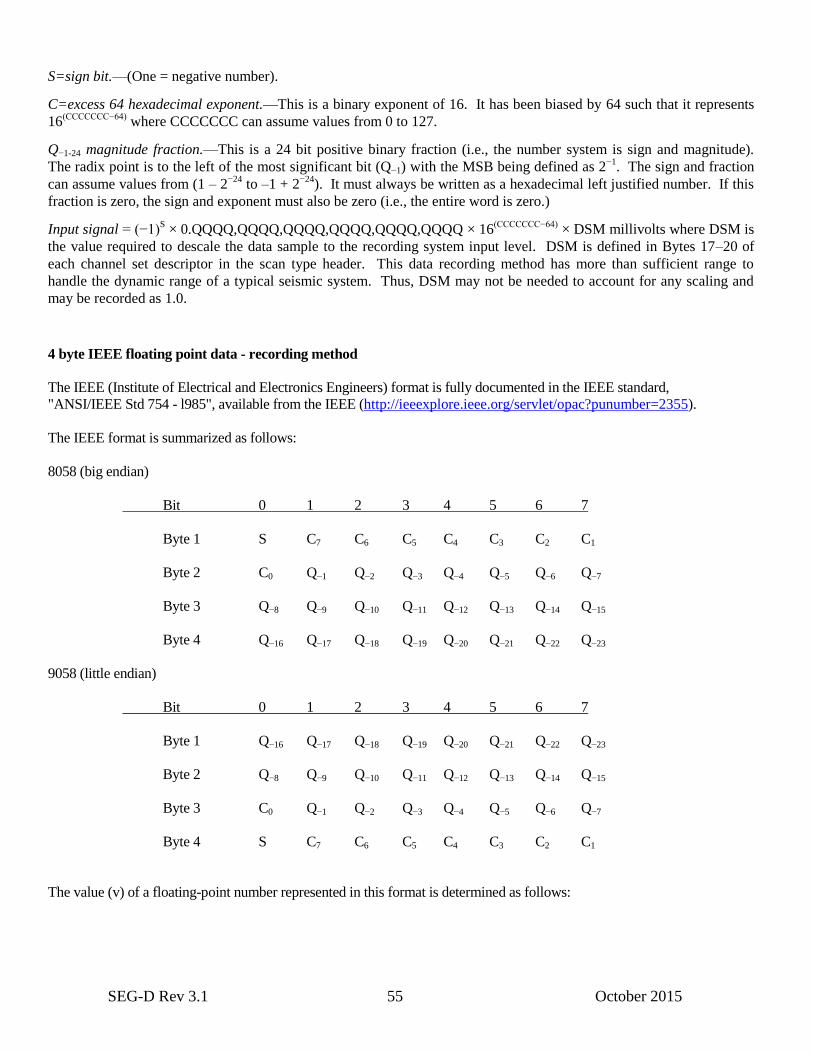
SEG-D Rev 3.1 55 October 2015
S=sign bit.—(One = negative number).
C=excess 64 hexadecimal exponent.—This is a binary exponent of 16. It has been biased by 64 such that it represents
16(CCCCCCC−64)
where CCCCCCC can assume values from 0 to 127.
Q−1-24 magnitude fraction.—This is a 24 bit positive binary fraction (i.e., the number system is sign and magnitude).
The radix point is to the left of the most significant bit (Q−1) with the MSB being defined as 2−1
. The sign and fraction
can assume values from (1 – 2−24
to –1 + 2−24
). It must always be written as a hexadecimal left justified number. If this
fraction is zero, the sign and exponent must also be zero (i.e., the entire word is zero.)
Input signal = (−1)S × 0.QQQQ,QQQQ,QQQQ,QQQQ,QQQQ,QQQQ × 16
(CCCCCCC−64) × DSM millivolts where DSM is
the value required to descale the data sample to the recording system input level. DSM is defined in Bytes 17–20 of
each channel set descriptor in the scan type header. This data recording method has more than sufficient range to
handle the dynamic range of a typical seismic system. Thus, DSM may not be needed to account for any scaling and
may be recorded as 1.0.
4 byte IEEE floating point data - recording method
The IEEE (Institute of Electrical and Electronics Engineers) format is fully documented in the IEEE standard,
"ANSI/IEEE Std 754 - l985", available from the IEEE (http://ieeexplore.ieee.org/servlet/opac?punumber=2355).
The IEEE format is summarized as follows:
8058 (big endian)
Bit 0 1 2 3 4 5 6 7
Byte 1 S C7 C6 C5 C4 C3 C2 C1
Byte 2 C0 Q−1 Q−2 Q−3 Q−4 Q−5 Q−6 Q−7
Byte 3 Q−8 Q−9 Q−10 Q−11 Q−12 Q−13 Q−14 Q−15
Byte 4 Q−16 Q−17 Q−18 Q−19 Q−20 Q−21 Q−22 Q−23
9058 (little endian)
Bit 0 1 2 3 4 5 6 7
Byte 1 Q−16 Q−17 Q−18 Q−19 Q−20 Q−21 Q−22 Q−23
Byte 2 Q−8 Q−9 Q−10 Q−11 Q−12 Q−13 Q−14 Q−15
Byte 3 C0 Q−1 Q−2 Q−3 Q−4 Q−5 Q−6 Q−7
Byte 4 S C7 C6 C5 C4 C3 C2 C1
The value (v) of a floating-point number represented in this format is determined as follows:

SEG-D Rev 3.1 56 October 2015
if e = 255 & f ≠ 0. .v = NaN Not-a-Number (see Note 1)
if e = 255 & f = 0. .v = (−1)s × Overflow
if 0 < e < 255 . . . . .v = (−1)s × 2
e−127 × (1.f) Normalized
if e = 0 & f ≠ 0. . . .v = (−1)s × 2
e−126 × (0.f) Denormalized
if e = 0 & f = 0. . . .v = (−1)s × 0 ± zero
where e = binary value of all C's (exponent)
f = binary value of all Q's (fraction)
NOTE 1. A Not-a-Number (NaN) is interpreted as an invalid number. All other numbers are valid and
interpreted as described above.
Input signal = v × DSM millivolts where DSM is the value required to descale the data sample to the recording system
input level. DSM is defined in Bytes 17–20 of each channel set descriptor in the scan type header. This data recording
method has more than sufficient range to handle the dynamic range of a typical seismic system. Thus, DSM may not be
needed to account for any scaling and may be recorded as 1.0.
8 byte IEEE floating point data – recording method
The IEEE (Institute of Electrical and Electronics Engineers) format is fully documented in the IEEE standard,
"ANSI/IEEE Std 754 - l985", available from the IEEE (http://ieeexplore.ieee.org/servlet/opac?punumber=2355).
The IEEE format is summarized as follows:
8080 (big endian):
Bit 0 1 2 3 4 5 6 7
Byte 1 S C11 C10 C9 C8 C7 C6 C5
Byte 2 C4 C3 C2 C1 Q−1 Q−2 Q−3 Q−4
Byte 3 Q−5 Q−6 Q−7 Q−8 Q−9 Q−10 Q−11 Q−12
Byte 4 Q−13 Q−14 Q−15 Q−16 Q−17 Q−18 Q−19 Q−20
Byte 5 Q−21 Q−22 Q−23 Q−24 Q−25 Q−26 Q27 Q−28
Byte 6 Q−29 Q−30 Q−31 Q−32 Q−33 Q−34 Q−35 Q−36
Byte 7 Q−37 Q−38 Q−39 Q−40 Q−41 Q−42 Q−43 Q−44
Byte 8 Q−45 Q−46 Q−47 Q−48 Q−49 Q−50 Q−51 Q−52
9080 (little endian):
Bit 0 1 2 3 4 5 6 7
Byte 1 Q−45 Q−46 Q−47 Q−48 Q−49 Q−50 Q−51 Q−52
Byte 2 Q−37 Q−38 Q−39 Q−40 Q−41 Q−42 Q−43 Q−44
Byte 3 Q−29 Q−30 Q−31 Q−32 Q−33 Q−34 Q−35 Q−36
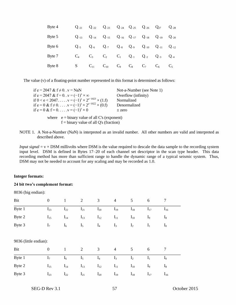
SEG-D Rev 3.1 57 October 2015
Byte 4 Q−21 Q−22 Q−23 Q−24 Q−25 Q−26 Q27 Q−28
Byte 5 Q−13 Q−14 Q−15 Q−16 Q−17 Q−18 Q−19 Q−20
Byte 6 Q−5 Q−6 Q−7 Q−8 Q−9 Q−10 Q−11 Q−12
Byte 7 C4 C3 C2 C1 Q−1 Q−2 Q−3 Q−4
Byte 8 S C11 C10 C9 C8 C7 C6 C5
The value (v) of a floating-point number represented in this format is determined as follows:
if e = 2047 & f ≠ 0. .v = NaN Not-a-Number (see Note 1)
if e = 2047 & f = 0. .v = (−1)s × Overflow (infinity)
if 0 < e < 2047. . . . . v = (−1)s × 2
e−1023 × (1.f) Normalized
if e = 0 & f ≠ 0. . . . .v = (−1)s × 2
e−1022 × (0.f) Denormalized
if e = 0 & f = 0. . . . .v = (−1)s × 0 ± zero
where e = binary value of all C's (exponent)
f = binary value of all Q's (fraction)
NOTE 1. A Not-a-Number (NaN) is interpreted as an invalid number. All other numbers are valid and interpreted as
described above.
Input signal = v × DSM millivolts where DSM is the value required to descale the data sample to the recording system
input level. DSM is defined in Bytes 17–20 of each channel set descriptor in the scan type header. This data
recording method has more than sufficient range to handle the dynamic range of a typical seismic system. Thus,
DSM may not be needed to account for any scaling and may be recorded as 1.0.
Integer formats:
24 bit two’s complement format:
8036 (big endian):
Bit 0 1 2 3 4 5 6 7
Byte 1 I23 I22 I21 I20 I19 I18 I17 I16
Byte 2 I15 I14 I13 I12 I11 I10 I9 I8
Byte 3 I7 I6 I5 I4 I3 I2 I1 I0
9036 (little endian):
Bit 0 1 2 3 4 5 6 7
Byte 1 I7 I6 I5 I4 I3 I2 I1 I0
Byte 2 I15 I14 I13 I12 I11 I10 I9 I8
Byte 3 I23 I22 I21 I20 I19 I18 I17 I16
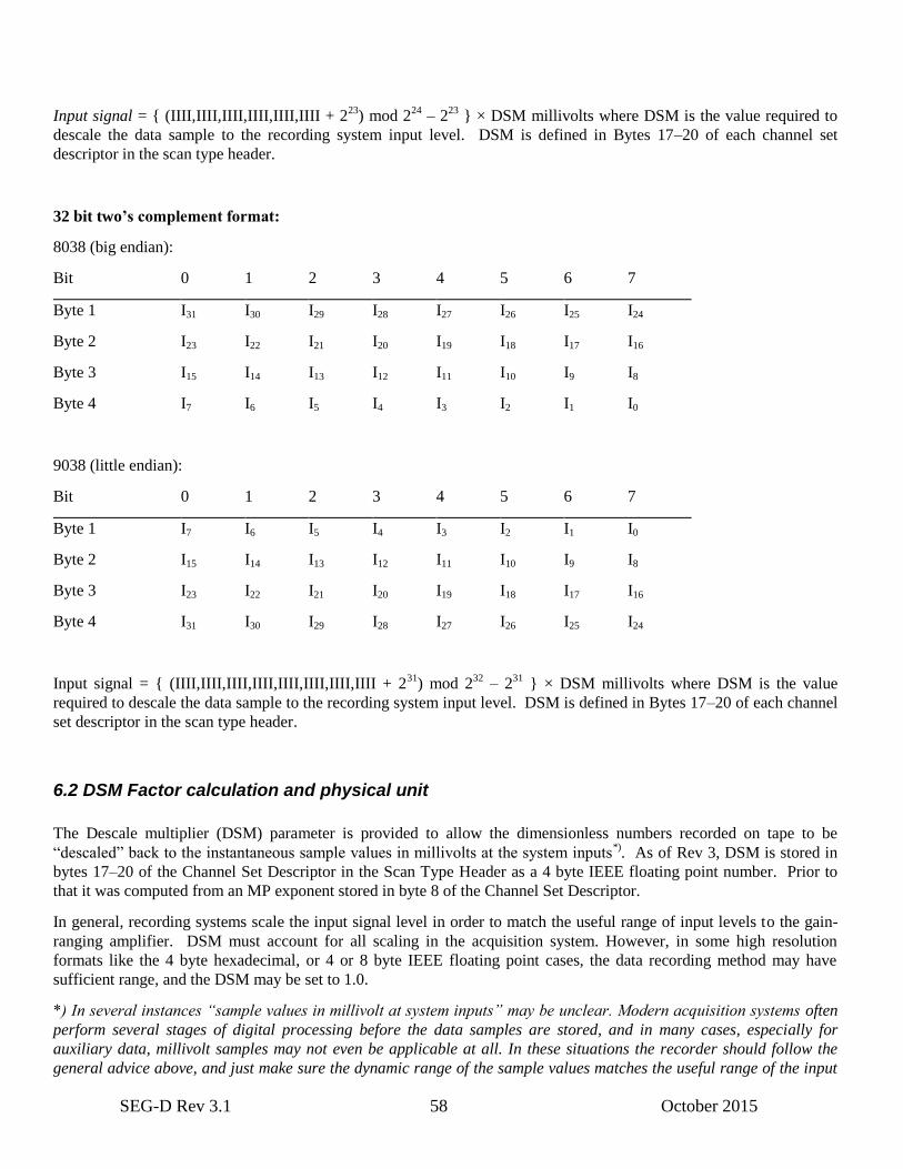
SEG-D Rev 3.1 58 October 2015
Input signal = { (IIII,IIII,IIII,IIII,IIII,IIII + 223
) mod 224
– 223
} × DSM millivolts where DSM is the value required to
descale the data sample to the recording system input level. DSM is defined in Bytes 17–20 of each channel set
descriptor in the scan type header.
32 bit two’s complement format:
8038 (big endian):
Bit 0 1 2 3 4 5 6 7
Byte 1 I31 I30 I29 I28 I27 I26 I25 I24
Byte 2 I23 I22 I21 I20 I19 I18 I17 I16
Byte 3 I15 I14 I13 I12 I11 I10 I9 I8
Byte 4 I7 I6 I5 I4 I3 I2 I1 I0
9038 (little endian):
Bit 0 1 2 3 4 5 6 7
Byte 1 I7 I6 I5 I4 I3 I2 I1 I0
Byte 2 I15 I14 I13 I12 I11 I10 I9 I8
Byte 3 I23 I22 I21 I20 I19 I18 I17 I16
Byte 4 I31 I30 I29 I28 I27 I26 I25 I24
Input signal = { (IIII,IIII,IIII,IIII,IIII,IIII,IIII,IIII + 231
) mod 232
– 231
} × DSM millivolts where DSM is the value
required to descale the data sample to the recording system input level. DSM is defined in Bytes 17–20 of each channel
set descriptor in the scan type header.
6.2 DSM Factor calculation and physical unit
The Descale multiplier (DSM) parameter is provided to allow the dimensionless numbers recorded on tape to be
“descaled” back to the instantaneous sample values in millivolts at the system inputs*). As of Rev 3, DSM is stored in
bytes 17–20 of the Channel Set Descriptor in the Scan Type Header as a 4 byte IEEE floating point number. Prior to
that it was computed from an MP exponent stored in byte 8 of the Channel Set Descriptor.
In general, recording systems scale the input signal level in order to match the useful range of input levels to the gain-
ranging amplifier. DSM must account for all scaling in the acquisition system. However, in some high resolution
formats like the 4 byte hexadecimal, or 4 or 8 byte IEEE floating point cases, the data recording method may have
sufficient range, and the DSM may be set to 1.0.
*) In several instances “sample values in millivolt at system inputs” may be unclear. Modern acquisition systems often
perform several stages of digital processing before the data samples are stored, and in many cases, especially for
auxiliary data, millivolt samples may not even be applicable at all. In these situations the recorder should follow the
general advice above, and just make sure the dynamic range of the sample values matches the useful range of the input

SEG-D Rev 3.1 59 October 2015
levels. In addition it is also highly recommended to store sensor sensitivity (in a Sensor Info Header extension block as
part of the Trace Header), to ensure the sample value can be converted to a physical unit.
Physical unit conversion
To be able to relate the seismic traces to external events it may be needed to convert the millivolt values in the traces to
the physical unit. The physical unit of the traces is listed in byte 62 of the Channel Set Descriptor. This is repeated in
byte 31 of Trace Header Extension block.
The following equation converts a trace sample value to a physical unit sample value
Vp = Vt * DSM * SS
Vp - Physical sample value
Vt - Trace sample value
DSM - Multiplication factor to convert to millivolt value
SS - Sensor sensitivity
The type of the physical unit are listed in the table found Chapter 8, Trace Header Extension, byte 31 definition. Typical
types are millibar (e.g. hydrophone data), millimeters/second (e.g. geophone data) or meters (e.g. depth measurement).
The sensor sensitivity (Sensor Info Header Extension bytes 9–12, 4 byte IEEE float) is the inverse of SS and the
millivolt sample value is divided by this sensor sensitivity to calculate the physical unit value.
SS = 1 / STY
Vp = Vt * DSM / STY
The sensor sensitivity in Sensor Info Header Extension also allows corrections for variations in the individual sensor
physical characteristics, like variations in sensor coupling, variations in electronics components, etc.
DSM may be written
DSM = 2MP
The calculation of MP for a data recording method is given by one of the following equations:
For floating point data:
1. MP = FS – PA – Cmax For binary exponents.
2. MP = FS – PA – 2 × Cmax For quaternary exponents.
3. MP = FS – PA – 4 × Cmax For hexadecimal exponents (except for the four byte excess 64
method).
4. MP = FS – PA – 4 × (Cmax – 64) For excess 64 hexadecimal exponents.
5. MP = FS – PA – (Cmax – 127) For 32 bit IEEE exponents.
6. MP = FS – PA – (Cmax – 1023) For 64 bit IEEE exponents.
Where:
2FS
= Converter full scale (millivolts),
2PA
= Minimum system gain,
Cmax = maximum value of the data exponent;
Cmax =
15 for binary exponents
7 for quaternary exponents,
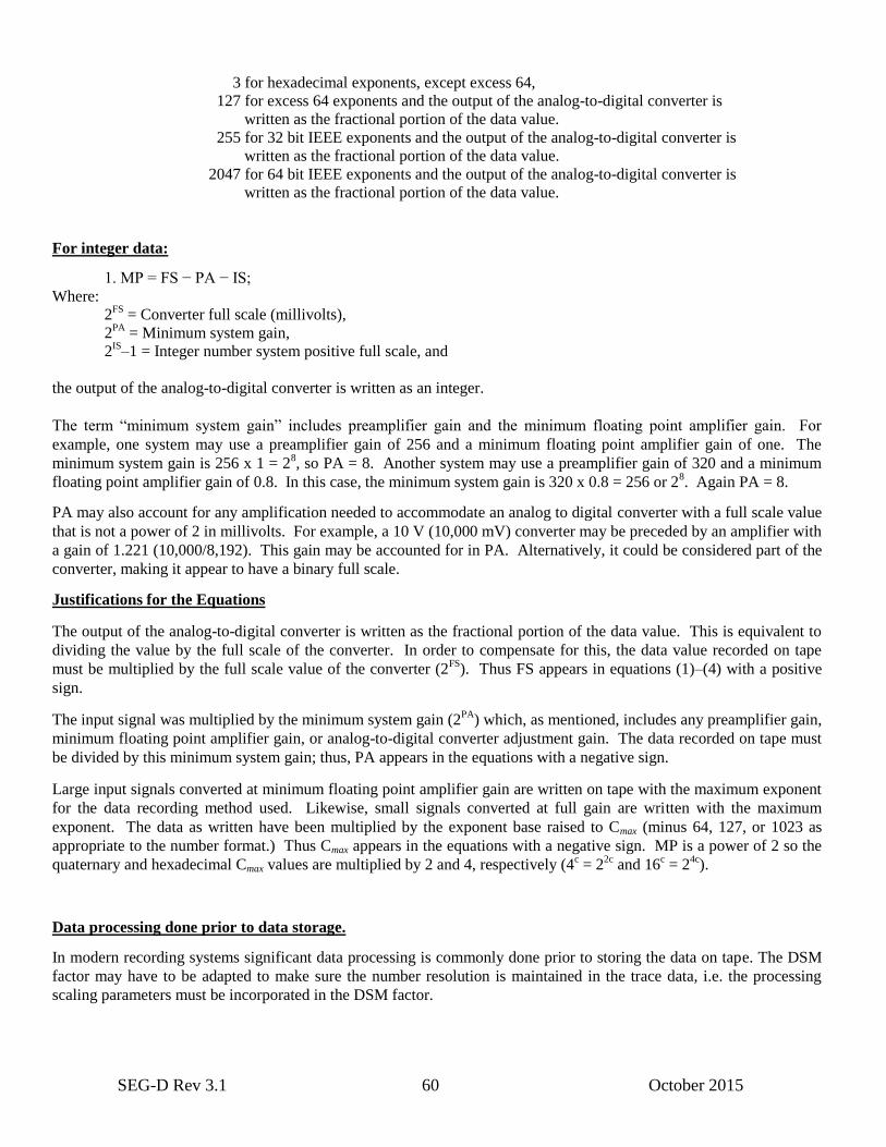
SEG-D Rev 3.1 60 October 2015
3 for hexadecimal exponents, except excess 64,
127 for excess 64 exponents and the output of the analog-to-digital converter is
written as the fractional portion of the data value.
255 for 32 bit IEEE exponents and the output of the analog-to-digital converter is
written as the fractional portion of the data value.
2047 for 64 bit IEEE exponents and the output of the analog-to-digital converter is
written as the fractional portion of the data value.
For integer data:
1. MP = FS − PA − IS;
Where:
2FS
= Converter full scale (millivolts),
2PA = Minimum system gain,
2IS
–1 = Integer number system positive full scale, and
the output of the analog-to-digital converter is written as an integer.
The term “minimum system gain” includes preamplifier gain and the minimum floating point amplifier gain. For
example, one system may use a preamplifier gain of 256 and a minimum floating point amplifier gain of one. The
minimum system gain is 256 x 1 = 28, so PA = 8. Another system may use a preamplifier gain of 320 and a minimum
floating point amplifier gain of 0.8. In this case, the minimum system gain is 320 x 0.8 = 256 or 28. Again PA = 8.
PA may also account for any amplification needed to accommodate an analog to digital converter with a full scale value
that is not a power of 2 in millivolts. For example, a 10 V (10,000 mV) converter may be preceded by an amplifier with
a gain of 1.221 (10,000/8,192). This gain may be accounted for in PA. Alternatively, it could be considered part of the
converter, making it appear to have a binary full scale.
Justifications for the Equations
The output of the analog-to-digital converter is written as the fractional portion of the data value. This is equivalent to
dividing the value by the full scale of the converter. In order to compensate for this, the data value recorded on tape
must be multiplied by the full scale value of the converter (2FS
). Thus FS appears in equations (1)–(4) with a positive
sign.
The input signal was multiplied by the minimum system gain (2PA
) which, as mentioned, includes any preamplifier gain,
minimum floating point amplifier gain, or analog-to-digital converter adjustment gain. The data recorded on tape must
be divided by this minimum system gain; thus, PA appears in the equations with a negative sign.
Large input signals converted at minimum floating point amplifier gain are written on tape with the maximum exponent
for the data recording method used. Likewise, small signals converted at full gain are written with the maximum
exponent. The data as written have been multiplied by the exponent base raised to Cmax (minus 64, 127, or 1023 as
appropriate to the number format.) Thus Cmax appears in the equations with a negative sign. MP is a power of 2 so the
quaternary and hexadecimal Cmax values are multiplied by 2 and 4, respectively (4c = 2
2c and 16
c = 2
4c).
Data processing done prior to data storage.
In modern recording systems significant data processing is commonly done prior to storing the data on tape. The DSM
factor may have to be adapted to make sure the number resolution is maintained in the trace data, i.e. the processing
scaling parameters must be incorporated in the DSM factor.
SEG-D Rev 3.1 61 October 2015
6.3 Sensor calibration
Trace Header frequency domain calibration
SEGD supports storing individual sensor calibration values in Trace Header Extension blocks (see Sensor Calibration
Header)”. Each 32 byte Sensor Calibration Header block contains two frequency/amplitude/phase groups, and multiple
blocks may be used to define the complete frequency domain calibration function for the sensor. Sensor Calibration
Header block allows a maximum of about 500 frequencies per trace, assuming no other meta-information exist in the trace
header
The calibration corrected sensor value is achieved by converting the time series trace value to frequency domain, and
multiplying with the calibration function
Vcalibrated = Fc . Vtrace
Where
Vcalibrated = Calibration corrected trace signal (in frequency domain)
Fc = Sensor calibration transfer function as described by the values in the sensor calibration header.
Vtrace = The uncorrected trace value (in frequency domain)
The sensor calibration values in addition to the individual Sensor Sensitivity values can be used to correct for most sensor
variations needed to achieve a high fidelity signal needed in modern seismic acquisition systems.
Calibration Channel – time domain
A Calibration Channel Set can be used if time series calibration is preferred. The Calibration Channel Set also allows a
more high fidelity calibration compared to the Trace Header Extension blocks. The frequency and length of the calibration
channel may be adjusted to achieve the accuracy required. Calibration Channel Sets has Channel type set to F016 in
Channel Set Descriptor byte 4. The Calibration Channel is a time series signal that can be correlated with the trace value
to achieve a calibrated trace signal. By converting both the trace and calibration trace time series to frequency domain, the
formula shown above can be used. The indices in the Trace Header Extension block determine which trace the calibration
trace applies to.
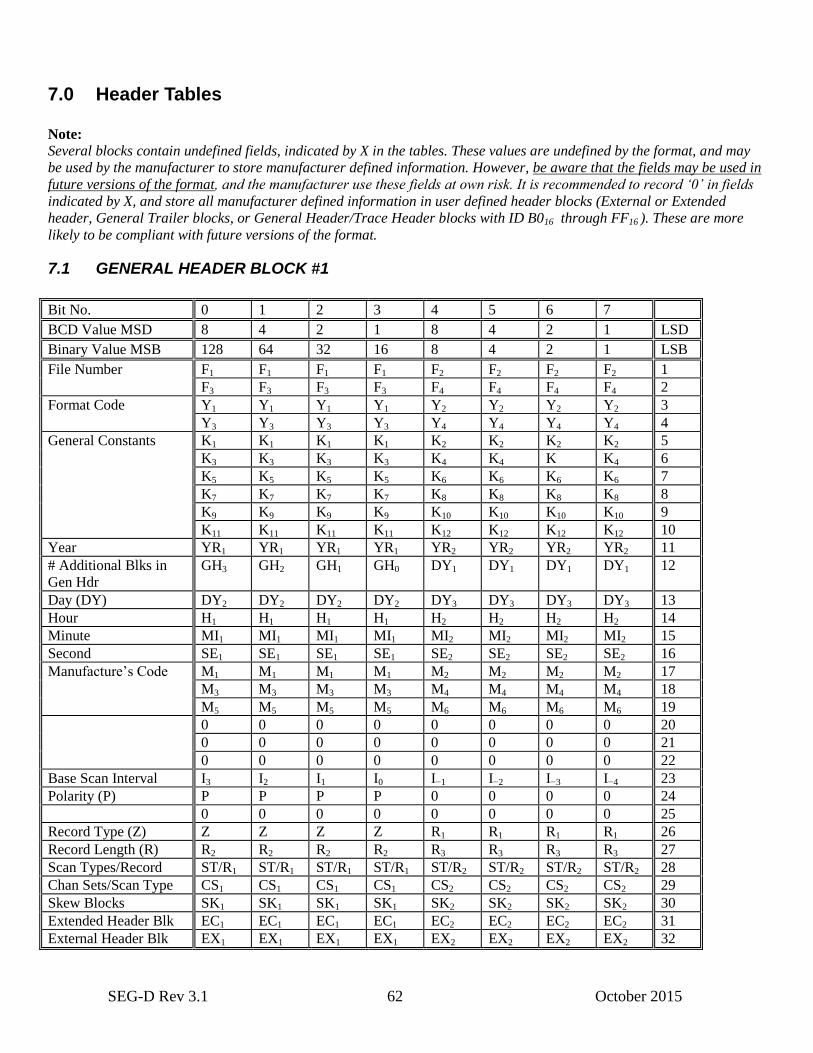
SEG-D Rev 3.1 62 October 2015
7.0 Header Tables
Note:
Several blocks contain undefined fields, indicated by X in the tables. These values are undefined by the format, and may
be used by the manufacturer to store manufacturer defined information. However, be aware that the fields may be used in
future versions of the format, and the manufacturer use these fields at own risk. It is recommended to record ‘0’ in fields
indicated by X, and store all manufacturer defined information in user defined header blocks (External or Extended
header, General Trailer blocks, or General Header/Trace Header blocks with ID B016 through FF16 ). These are more
likely to be compliant with future versions of the format.
7.1 GENERAL HEADER BLOCK #1
Bit No. 0 1 2 3 4 5 6 7
BCD Value MSD 8 4 2 1 8 4 2 1 LSD
Binary Value MSB 128 64 32 16 8 4 2 1 LSB
File Number F1 F1 F1 F1 F2 F2 F2 F2 1
F3 F3 F3 F3 F4 F4 F4 F4 2
Format Code Y1 Y1 Y1 Y1 Y2 Y2 Y2 Y2 3
Y3 Y3 Y3 Y3 Y4 Y4 Y4 Y4 4
General Constants K1 K1 K1 K1 K2 K2 K2 K2 5
K3 K3 K3 K3 K4 K4 K K4 6
K5 K5 K5 K5 K6 K6 K6 K6 7
K7 K7 K7 K7 K8 K8 K8 K8 8
K9 K9 K9 K9 K10 K10 K10 K10 9
K11 K11 K11 K11 K12 K12 K12 K12 10
Year YR1 YR1 YR1 YR1 YR2 YR2 YR2 YR2 11
# Additional Blks in
Gen Hdr
GH3 GH2 GH1 GH0 DY1 DY1 DY1 DY1 12
Day (DY) DY2 DY2 DY2 DY2 DY3 DY3 DY3 DY3 13
Hour H1 H1 H1 H1 H2 H2 H2 H2 14
Minute MI1 MI1 MI1 MI1 MI2 MI2 MI2 MI2 15
Second SE1 SE1 SE1 SE1 SE2 SE2 SE2 SE2 16
Manufacture’s Code M1 M1 M1 M1 M2 M2 M2 M2 17
M3 M3 M3 M3 M4 M4 M4 M4 18
M5 M5 M5 M5 M6 M6 M6 M6 19
0 0 0 0 0 0 0 0 20
0 0 0 0 0 0 0 0 21
0 0 0 0 0 0 0 0 22
Base Scan Interval I3 I2 I1 I0 I−1 I−2 I−3 I−4 23
Polarity (P) P P P P 0 0 0 0 24
0 0 0 0 0 0 0 0 25
Record Type (Z) Z Z Z Z R1 R1 R1 R1 26
Record Length (R) R2 R2 R2 R2 R3 R3 R3 R3 27
Scan Types/Record ST/R1 ST/R1 ST/R1 ST/R1 ST/R2 ST/R2 ST/R2 ST/R2 28
Chan Sets/Scan Type CS1 CS1 CS1 CS1 CS2 CS2 CS2 CS2 29
Skew Blocks SK1 SK1 SK1 SK1 SK2 SK2 SK2 SK2 30
Extended Header Blk EC1 EC1 EC1 EC1 EC2 EC2 EC2 EC2 31
External Header Blk EX1 EX1 EX1 EX1 EX2 EX2 EX2 EX2 32
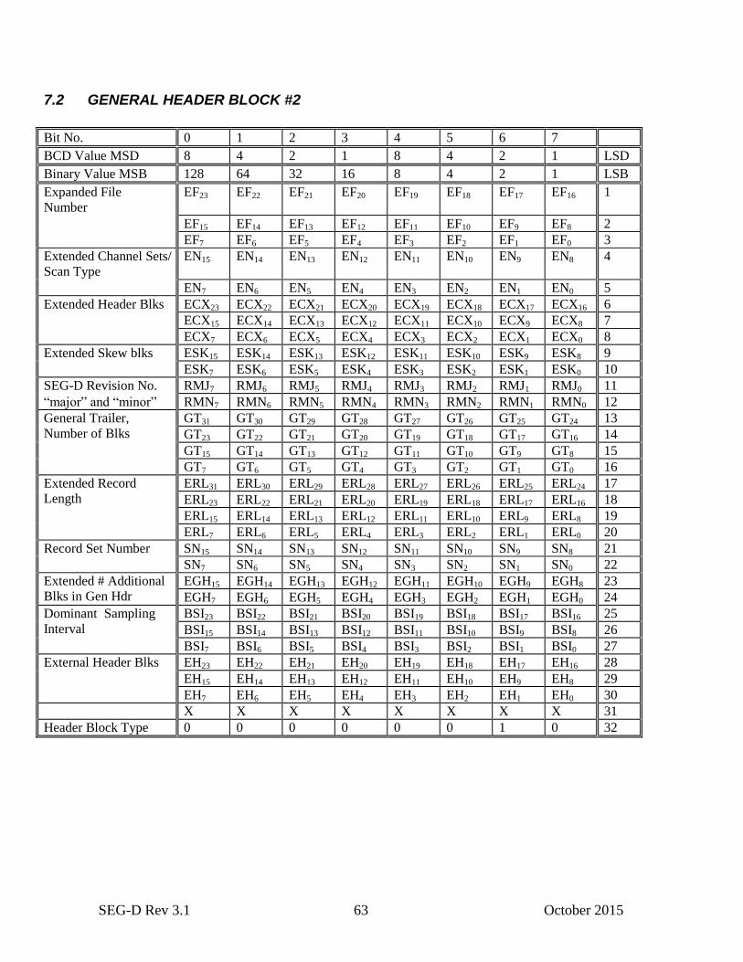
SEG-D Rev 3.1 63 October 2015
7.2 GENERAL HEADER BLOCK #2
Bit No. 0 1 2 3 4 5 6 7
BCD Value MSD 8 4 2 1 8 4 2 1 LSD
Binary Value MSB 128 64 32 16 8 4 2 1 LSB
Expanded File
Number
EF23 EF22 EF21 EF20 EF19 EF18 EF17 EF16 1
EF15 EF14 EF13 EF12 EF11 EF10 EF9 EF8 2
EF7 EF6 EF5 EF4 EF3 EF2 EF1 EF0 3
Extended Channel Sets/
Scan Type
EN15 EN14 EN13 EN12 EN11 EN10 EN9 EN8 4
EN7 EN6 EN5 EN4 EN3 EN2 EN1 EN0 5
Extended Header Blks ECX23 ECX22 ECX21 ECX20 ECX19 ECX18 ECX17 ECX16 6
ECX15 ECX14 ECX13 ECX12 ECX11 ECX10 ECX9 ECX8 7
ECX7 ECX6 ECX5 ECX4 ECX3 ECX2 ECX1 ECX0 8
Extended Skew blks ESK15 ESK14 ESK13 ESK12 ESK11 ESK10 ESK9 ESK8 9
ESK7 ESK6 ESK5 ESK4 ESK3 ESK2 ESK1 ESK0 10
SEG-D Revision No. RMJ7 RMJ6 RMJ5 RMJ4 RMJ3 RMJ2 RMJ1 RMJ0 11
“major” and “minor” RMN7 RMN6 RMN5 RMN4 RMN3 RMN2 RMN1 RMN0 12
General Trailer,
Number of Blks
GT31 GT30 GT29 GT28 GT27 GT26 GT25 GT24 13
GT23 GT22 GT21 GT20 GT19 GT18 GT17 GT16 14
GT15 GT14 GT13 GT12 GT11 GT10 GT9 GT8 15
GT7 GT6 GT5 GT4 GT3 GT2 GT1 GT0 16
Extended Record
Length
ERL31 ERL30 ERL29 ERL28 ERL27 ERL26 ERL25 ERL24 17
ERL23 ERL22 ERL21 ERL20 ERL19 ERL18 ERL17 ERL16 18
ERL15 ERL14 ERL13 ERL12 ERL11 ERL10 ERL9 ERL8 19
ERL7 ERL6 ERL5 ERL4 ERL3 ERL2 ERL1 ERL0 20
Record Set Number SN15 SN14 SN13 SN12 SN11 SN10 SN9 SN8 21
SN7 SN6 SN5 SN4 SN3 SN2 SN1 SN0 22
Extended # Additional
Blks in Gen Hdr
EGH15 EGH14 EGH13 EGH12 EGH11 EGH10 EGH9 EGH8 23
EGH7 EGH6 EGH5 EGH4 EGH3 EGH2 EGH1 EGH0 24
Dominant Sampling Sample
Interval
BSI23 BSI22 BSI21 BSI20 BSI19 BSI18 BSI17 BSI16 25
BSI15 BSI14 BSI13 BSI12 BSI11 BSI10 BSI9 BSI8 26
BSI7 BSI6 BSI5 BSI4 BSI3 BSI2 BSI1 BSI0 27
External Header Blks EH23 EH22 EH21 EH20 EH19 EH18 EH17 EH16 28
EH15 EH14 EH13 EH12 EH11 EH10 EH9 EH8 29
EH7 EH6 EH5 EH4 EH3 EH2 EH1 EH0 30
X X X X X X X X 31
Header Block Type 0 0 0 0 0 0 1 0 32
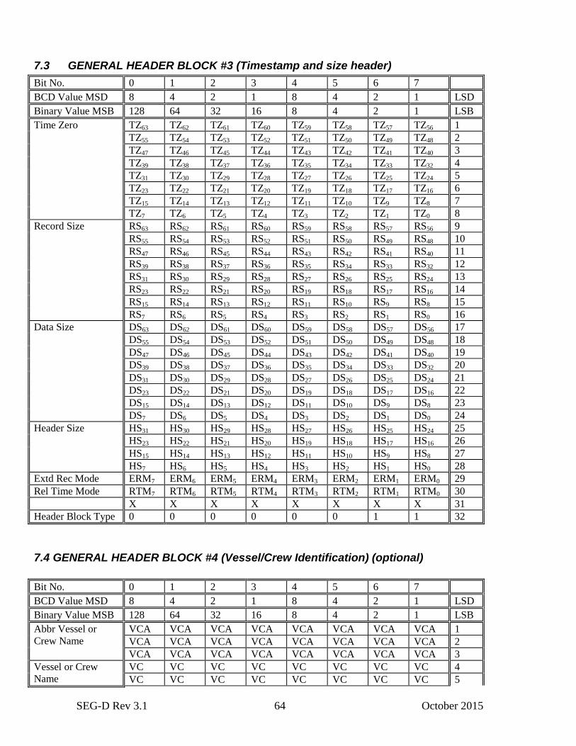
SEG-D Rev 3.1 64 October 2015
7.3 GENERAL HEADER BLOCK #3 (Timestamp and size header)
Bit No. 0 1 2 3 4 5 6 7
BCD Value MSD 8 4 2 1 8 4 2 1 LSD
Binary Value MSB 128 64 32 16 8 4 2 1 LSB
Time Zero TZ63 TZ62 TZ61 TZ60 TZ59 TZ58 TZ57 TZ56 1
TZ55 TZ54 TZ53 TZ52 TZ51 TZ50 TZ49 TZ48 2
TZ47 TZ46 TZ45 TZ44 TZ43 TZ42 TZ41 TZ40 3
TZ39 TZ38 TZ37 TZ36 TZ35 TZ34 TZ33 TZ32 4
TZ31 TZ30 TZ29 TZ28 TZ27 TZ26 TZ25 TZ24 5
TZ23 TZ22 TZ21 TZ20 TZ19 TZ18 TZ17 TZ16 6
TZ15 TZ14 TZ13 TZ12 TZ11 TZ10 TZ9 TZ8 7
TZ7 TZ6 TZ5 TZ4 TZ3 TZ2 TZ1 TZ0 8
Record Size RS63 RS62 RS61 RS60 RS59 RS58 RS57 RS56 9
RS55 RS54 RS53 RS52 RS51 RS50 RS49 RS48 10
RS47 RS46 RS45 RS44 RS43 RS42 RS41 RS40 11
RS39 RS38 RS37 RS36 RS35 RS34 RS33 RS32 12
RS31 RS30 RS29 RS28 RS27 RS26 RS25 RS24 13
RS23 RS22 RS21 RS20 RS19 RS18 RS17 RS16 14
RS15 RS14 RS13 RS12 RS11 RS10 RS9 RS8 15
RS7 RS6 RS5 RS4 RS3 RS2 RS1 RS0 16
Data Size DS63 DS62 DS61 DS60 DS59 DS58 DS57 DS56 17
DS55 DS54 DS53 DS52 DS51 DS50 DS49 DS48 18
DS47 DS46 DS45 DS44 DS43 DS42 DS41 DS40 19
DS39 DS38 DS37 DS36 DS35 DS34 DS33 DS32 20
DS31 DS30 DS29 DS28 DS27 DS26 DS25 DS24 21
DS23 DS22 DS21 DS20 DS19 DS18 DS17 DS16 22
DS15 DS14 DS13 DS12 DS11 DS10 DS9 DS8 23
DS7 DS6 DS5 DS4 DS3 DS2 DS1 DS0 24
Header Size HS31 HS30 HS29 HS28 HS27 HS26 HS25 HS24 25
HS23 HS22 HS21 HS20 HS19 HS18 HS17 HS16 26
HS15 HS14 HS13 HS12 HS11 HS10 HS9 HS8 27
HS7 HS6 HS5 HS4 HS3 HS2 HS1 HS0 28
Extd Rec Mode ERM7 ERM6 ERM5 ERM4 ERM3 ERM2 ERM1 ERM0 29
Rel Time Mode RTM7 RTM6 RTM5 RTM4 RTM3 RTM2 RTM1 RTM0 30
X X X X X X X X 31
Header Block Type 0 0 0 0 0 0 1 1 32
7.4 GENERAL HEADER BLOCK #4 (Vessel/Crew Identification) (optional)
Bit No. 0 1 2 3 4 5 6 7
BCD Value MSD 8 4 2 1 8 4 2 1 LSD
Binary Value MSB 128 64 32 16 8 4 2 1 LSB
Abbr Vessel or
Crew Name
VCA VCA VCA VCA VCA VCA VCA VCA 1
VCA VCA VCA VCA VCA VCA VCA VCA 2
VCA VCA VCA VCA VCA VCA VCA VCA 3
Vessel or Crew
Name
VC VC VC VC VC VC VC VC 4
VC VC VC VC VC VC VC VC 5
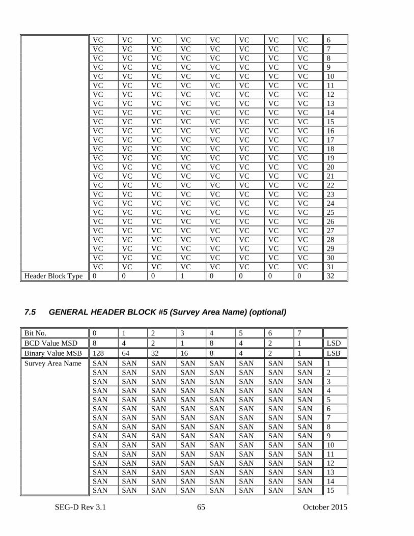
SEG-D Rev 3.1 65 October 2015
VC VC VC VC VC VC VC VC 6
VC VC VC VC VC VC VC VC 7
VC VC VC VC VC VC VC VC 8
VC VC VC VC VC VC VC VC 9
VC VC VC VC VC VC VC VC 10
VC VC VC VC VC VC VC VC 11
VC VC VC VC VC VC VC VC 12
VC VC VC VC VC VC VC VC 13
VC VC VC VC VC VC VC VC 14
VC VC VC VC VC VC VC VC 15
VC VC VC VC VC VC VC VC 16
VC VC VC VC VC VC VC VC 17
VC VC VC VC VC VC VC VC 18
VC VC VC VC VC VC VC VC 19
VC VC VC VC VC VC VC VC 20
VC VC VC VC VC VC VC VC 21
VC VC VC VC VC VC VC VC 22
VC VC VC VC VC VC VC VC 23
VC VC VC VC VC VC VC VC 24
VC VC VC VC VC VC VC VC 25
VC VC VC VC VC VC VC VC 26
VC VC VC VC VC VC VC VC 27
VC VC VC VC VC VC VC VC 28
VC VC VC VC VC VC VC VC 29
VC VC VC VC VC VC VC VC 30
VC VC VC VC VC VC VC VC 31
Header Block Type 0 0 0 1 0 0 0 0 32
7.5 GENERAL HEADER BLOCK #5 (Survey Area Name) (optional)
Bit No. 0 1 2 3 4 5 6 7
BCD Value MSD 8 4 2 1 8 4 2 1 LSD
Binary Value MSB 128 64 32 16 8 4 2 1 LSB
Survey Area Name SAN SAN SAN SAN SAN SAN SAN SAN 1
SAN SAN SAN SAN SAN SAN SAN SAN 2
SAN SAN SAN SAN SAN SAN SAN SAN 3
SAN SAN SAN SAN SAN SAN SAN SAN 4
SAN SAN SAN SAN SAN SAN SAN SAN 5
SAN SAN SAN SAN SAN SAN SAN SAN 6
SAN SAN SAN SAN SAN SAN SAN SAN 7
SAN SAN SAN SAN SAN SAN SAN SAN 8
SAN SAN SAN SAN SAN SAN SAN SAN 9
SAN SAN SAN SAN SAN SAN SAN SAN 10
SAN SAN SAN SAN SAN SAN SAN SAN 11
SAN SAN SAN SAN SAN SAN SAN SAN 12
SAN SAN SAN SAN SAN SAN SAN SAN 13
SAN SAN SAN SAN SAN SAN SAN SAN 14
SAN SAN SAN SAN SAN SAN SAN SAN 15
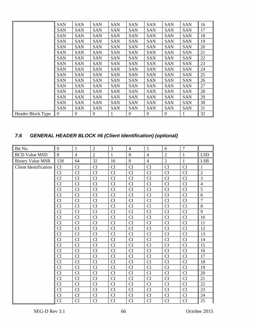
SEG-D Rev 3.1 66 October 2015
SAN SAN SAN SAN SAN SAN SAN SAN 16
SAN SAN SAN SAN SAN SAN SAN SAN 17
SAN SAN SAN SAN SAN SAN SAN SAN 18
SAN SAN SAN SAN SAN SAN SAN SAN 19
SAN SAN SAN SAN SAN SAN SAN SAN 20
SAN SAN SAN SAN SAN SAN SAN SAN 21
SAN SAN SAN SAN SAN SAN SAN SAN 22
SAN SAN SAN SAN SAN SAN SAN SAN 23
SAN SAN SAN SAN SAN SAN SAN SAN 24
SAN SAN SAN SAN SAN SAN SAN SAN 25
SAN SAN SAN SAN SAN SAN SAN SAN 26
SAN SAN SAN SAN SAN SAN SAN SAN 27
SAN SAN SAN SAN SAN SAN SAN SAN 28
SAN SAN SAN SAN SAN SAN SAN SAN 29
SAN SAN SAN SAN SAN SAN SAN SAN 30
SAN SAN SAN SAN SAN SAN SAN SAN 31
Header Block Type 0 0 0 1 0 0 0 1 32
7.6 GENERAL HEADER BLOCK #6 (Client Identification) (optional)
Bit No. 0 1 2 3 4 5 6 7
BCD Value MSD 8 4 2 1 8 4 2 1 LSD
Binary Value MSB 128 64 32 16 8 4 2 1 LSB
Client Identification CI CI CI CI CI CI CI CI 1
CI CI CI CI CI CI CI CI 2
CI CI CI CI CI CI CI CI 3
CI CI CI CI CI CI CI CI 4
CI CI CI CI CI CI CI CI 5
CI CI CI CI CI CI CI CI 6
CI CI CI CI CI CI CI CI 7
CI CI CI CI CI CI CI CI 8
CI CI CI CI CI CI CI CI 9
CI CI CI CI CI CI CI CI 10
CI CI CI CI CI CI CI CI 11
CI CI CI CI CI CI CI CI 12
CI CI CI CI CI CI CI CI 13
CI CI CI CI CI CI CI CI 14
CI CI CI CI CI CI CI CI 15
CI CI CI CI CI CI CI CI 16
CI CI CI CI CI CI CI CI 17
CI CI CI CI CI CI CI CI 18
CI CI CI CI CI CI CI CI 19
CI CI CI CI CI CI CI CI 20
CI CI CI CI CI CI CI CI 21
CI CI CI CI CI CI CI CI 22
CI CI CI CI CI CI CI CI 23
CI CI CI CI CI CI CI CI 24
CI CI CI CI CI CI CI CI 25
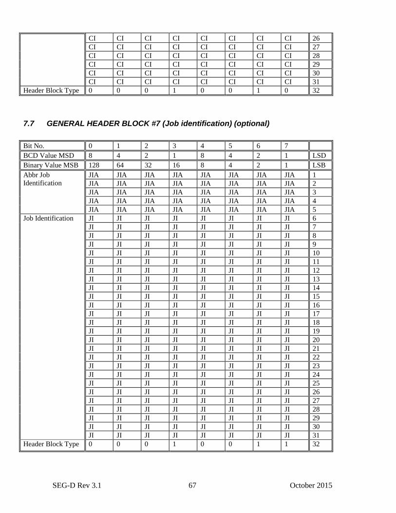
SEG-D Rev 3.1 67 October 2015
CI CI CI CI CI CI CI CI 26
CI CI CI CI CI CI CI CI 27
CI CI CI CI CI CI CI CI 28
CI CI CI CI CI CI CI CI 29
CI CI CI CI CI CI CI CI 30
CI CI CI CI CI CI CI CI 31
Header Block Type 0 0 0 1 0 0 1 0 32
7.7 GENERAL HEADER BLOCK #7 (Job identification) (optional)
Bit No. 0 1 2 3 4 5 6 7
BCD Value MSD 8 4 2 1 8 4 2 1 LSD
Binary Value MSB 128 64 32 16 8 4 2 1 LSB
Abbr Job
Identification
JIA JIA JIA JIA JIA JIA JIA JIA 1
JIA JIA JIA JIA JIA JIA JIA JIA 2
JIA JIA JIA JIA JIA JIA JIA JIA 3
JIA JIA JIA JIA JIA JIA JIA JIA 4
JIA JIA JIA JIA JIA JIA JIA JIA 5
Job Identification
JI JI JI JI JI JI JI JI 6
JI JI JI JI JI JI JI JI 7
JI JI JI JI JI JI JI JI 8
JI JI JI JI JI JI JI JI 9
JI JI JI JI JI JI JI JI 10
JI JI JI JI JI JI JI JI 11
JI JI JI JI JI JI JI JI 12
JI JI JI JI JI JI JI JI 13
JI JI JI JI JI JI JI JI 14
JI JI JI JI JI JI JI JI 15
JI JI JI JI JI JI JI JI 16
JI JI JI JI JI JI JI JI 17
JI JI JI JI JI JI JI JI 18
JI JI JI JI JI JI JI JI 19
JI JI JI JI JI JI JI JI 20
JI JI JI JI JI JI JI JI 21
JI JI JI JI JI JI JI JI 22
JI JI JI JI JI JI JI JI 23
JI JI JI JI JI JI JI JI 24
JI JI JI JI JI JI JI JI 25
JI JI JI JI JI JI JI JI 26
JI JI JI JI JI JI JI JI 27
JI JI JI JI JI JI JI JI 28
JI JI JI JI JI JI JI JI 29
JI JI JI JI JI JI JI JI 30
JI JI JI JI JI JI JI JI 31
Header Block Type 0 0 0 1 0 0 1 1 32

SEG-D Rev 3.1 68 October 2015
7.8 GENERAL HEADER BLOCK #8 (Line identification) (optional)
Bit No. 0 1 2 3 4 5 6 7
BCD Value MSD 8 4 2 1 8 4 2 1 LSD
Binary Value MSB 128 64 32 16 8 4 2 1 LSB
Line Abbreviation LA LA LA LA LA LA LA LA 1
LA LA LA LA LA LA LA LA 2
LA LA LA LA LA LA LA LA 3
LA LA LA LA LA LA LA LA 4
LA LA LA LA LA LA LA LA 5
LA LA LA LA LA LA LA LA 6
LA LA LA LA LA LA LA LA 7
Line Identification
LI LI LI LI LI LI LI LI 8
LI LI LI LI LI LI LI LI 9
LI LI LI LI LI LI LI LI 10
LI LI LI LI LI LI LI LI 11
LI LI LI LI LI LI LI LI 12
LI LI LI LI LI LI LI LI 13
LI LI LI LI LI LI LI LI 14
LI LI LI LI LI LI LI LI 15
LI LI LI LI LI LI LI LI 16
LI LI LI LI LI LI LI LI 17
LI LI LI LI LI LI LI LI 18
LI LI LI LI LI LI LI LI 19
LI LI LI LI LI LI LI LI 20
LI LI LI LI LI LI LI LI 21
LI LI LI LI LI LI LI LI 22
LI LI LI LI LI LI LI LI 23
LI LI LI LI LI LI LI LI 24
LI LI LI LI LI LI LI LI 25
LI LI LI LI LI LI LI LI 26
LI LI LI LI LI LI LI LI 27
LI LI LI LI LI LI LI LI 28
LI LI LI LI LI LI LI LI 29
LI LI LI LI LI LI LI LI 30
LI LI LI LI LI LI LI LI 31
Header Block Type 0 0 0 1 0 1 0 0 32
7.9 SOURCE DESCRIPTION BLOCK (optional)
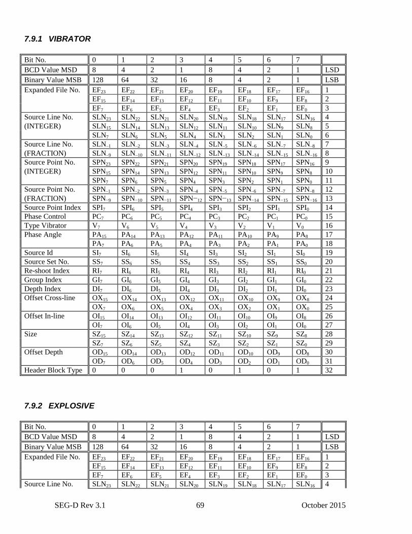
SEG-D Rev 3.1 69 October 2015
7.9.1 VIBRATOR
Bit No. 0 1 2 3 4 5 6 7
BCD Value MSD 8 4 2 1 8 4 2 1 LSD
Binary Value MSB 128 64 32 16 8 4 2 1 LSB
Expanded File No. EF23 EF22 EF21 EF20 EF19 EF18 EF17 EF16 1
EF15 EF14 EF13 EF12 EF11 EF10 EF9 EF8 2
EF7 EF6 EF5 EF4 EF3 EF2 EF1 EF0 3
Source Line No. SLN23 SLN22 SLN21 SLN20 SLN19 SLN18 SLN17 SLN16 4
(INTEGER) SLN15 SLN14 SLN13 SLN12 SLN11 SLN10 SLN9 SLN8 5
SLN7 SLN6 SLN5 SLN4 SLN3 SLN2 SLN1 SLN0 6
Source Line No. SLN–1 SLN–2 SLN–3 SLN–4 SLN–5 SLN–6 SLN–7 SLN–8 7
(FRACTION) SLN–9 SLN–10 SLN–11 SLN–12 SLN–13 SLN–14 SLN–15 SLN–16 8
Source Point No. SPN23 SPN22 SPN21 SPN20 SPN19 SPN18 SPN17 SPN16 9
(INTEGER) SPN15 SPN14 SPN13 SPN12 SPN11 SPN10 SPN9 SPN8 10
SPN7 SPN6 SPN5 SPN4 SPN3 SPN2 SPN1 SPN0 11
Source Point No. SPN–1 SPN–2 SPN–3 SPN–4 SPN–5 SPN–6 SPN–7 SPN–8 12
(FRACTION) SPN−9 SPN−10 SPN−11 SPN−12 SPN−13 SPN−14 SPN−15 SPN−16 13
Source Point Index SPI7 SPI6 SPI5 SPI4 SPI3 SPI2 SPI1 SPI0 14
Phase Control PC7 PC6 PC5 PC4 PC3 PC2 PC1 PC0 15
Type Vibrator V7 V6 V5 V4 V3 V2 V1 V0 16
Phase Angle PA15 PA14 PA13 PA12 PA11 PA10 PA9 PA8 17
PA7 PA6 PA5 PA4 PA3 PA2 PA1 PA0 18
Source Id SI7 SI6 SI5 SI4 SI3 SI2 SI1 SI0 19
Source Set No. SS7 SS6 SS5 SS4 SS3 SS2 SS1 SS0 20
Re-shoot Index RI7 RI6 RI5 RI4 RI3 RI2 RI1 RI0 21
Group Index GI7 GI6 GI5 GI4 GI3 GI2 GI1 GI0 22
Depth Index DI7 DI6 DI5 DI4 DI3 DI2 DI1 DI0 23
Offset Cross-line OX15 OX14 OX13 OX12 OX11 OX10 OX9 OX8 24
OX7 OX6 OX5 OX4 OX3 OX2 OX1 OX0 25
Offset In-line OI15 OI14 OI13 OI12 OI11 OI10 OI9 OI8 26
OI7 OI6 OI5 OI4 OI3 OI2 OI1 OI0 27
Size SZ15 SZ14 SZ13 SZ12 SZ11 SZ10 SZ9 SZ8 28
SZ7 SZ6 SZ5 SZ4 SZ3 SZ2 SZ1 SZ0 29
Offset Depth OD15 OD14 OD13 OD12 OD11 OD10 OD9 OD8 30
OD7 OD6 OD5 OD4 OD3 OD2 OD1 OD0 31
Header Block Type 0 0 0 1 0 1 0 1 32
7.9.2 EXPLOSIVE
Bit No. 0 1 2 3 4 5 6 7
BCD Value MSD 8 4 2 1 8 4 2 1 LSD
Binary Value MSB 128 64 32 16 8 4 2 1 LSB
Expanded File No. EF23 EF22 EF21 EF20 EF19 EF18 EF17 EF16 1
EF15 EF14 EF13 EF12 EF11 EF10 EF9 EF8 2
EF7 EF6 EF5 EF4 EF3 EF2 EF1 EF0 3
Source Line No. SLN23 SLN22 SLN21 SLN20 SLN19 SLN18 SLN17 SLN16 4
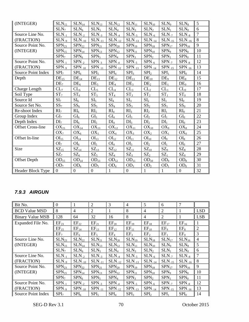
SEG-D Rev 3.1 70 October 2015
(INTEGER) SLN15 SLN14 SLN13 SLN12 SLN11 SLN10 SLN9 SLN8 5
SLN7 SLN6 SLN5 SLN4 SLN3 SLN2 SLN1 SLN0 6
Source Line No. SLN–1 SLN–2 SLN–3 SLN–4 SLN–5 SLN–6 SLN–7 SLN–8 7
(FRACTION) SLN–9 SLN–10 SLN–11 SLN–12 SLN–13 SLN–14 SLN–15 SLN–16 8
Source Point No. SPN23 SPN22 SPN21 SPN20 SPN19 SPN18 SPN17 SPN16 9
(INTEGER) SPN15 SPN14 SPN13 SPN12 SPN11 SPN10 SPN9 SPN8 10
SPN7 SPN6 SPN5 SPN4 SPN3 SPN2 SPN1 SPN0 11
Source Point No. SPN–1 SPN–2 SPN–3 SPN–4 SPN–5 SPN–6 SPN–7 SPN–8 12
(FRACTION) SPN–9 SPN–10 SPN–11 SPN–12 SPN–13 SPN–14 SPN–15 SPN–16 13
Source Point Index SPI7 SPI6 SPI5 SPI4 SPI3 SPI2 SPI1 SPI0 14
Depth DE15 DE14 DE13 DE12 DE11 DE10 DE9 DE8 15
DE7 DE6 DE5 DE4 DE3 DE2 DE1 DE0 16
Charge Length CL7 CL6 CL5 CL4 CL3 CL2 CL1 CL0 17
Soil Type ST7 ST6 ST5 ST4 ST3 ST2 ST1 ST0 18
Source Id SI7 SI6 SI5 SI4 SI3 SI2 SI1 SI0 19
Source Set No. SS7 SS6 SS5 SS4 SS3 SS2 SS1 SS0 20
Re-shoot Index RI7 RI6 RI5 RI4 RI3 RI2 RI1 RI0 21
Group Index GI7 GI6 GI5 GI4 GI3 GI2 GI1 GI0 22
Depth Index DI7 DI6 DI5 DI4 DI3 DI2 DI1 DI0 23
Offset Cross-line OX15 OX14 OX13 OX12 OX11 OX10 OX9 OX8 24
OX7 OX6 OX5 OX4 OX3 OX2 OX1 OX0 25
Offset In-line OI15 OI14 OI13 OI12 OI11 OI10 OI9 OI8 26
OI7 OI6 OI5 OI4 OI3 OI2 OI1 OI0 27
Size SZ15 SZ14 SZ13 SZ12 SZ11 SZ10 SZ9 SZ8 28
SZ7 SZ6 SZ5 SZ4 SZ3 SZ2 SZ1 SZ0 29
Offset Depth OD15 OD14 OD13 OD12 OD11 OD10 OD9 OD8 30
OD7 OD6 OD5 OD4 OD3 OD2 OD1 OD0 31
Header Block Type 0 0 0 1 0 1 1 0 32
7.9.3 AIRGUN
Bit No. 0 1 2 3 4 5 6 7
BCD Value MSD 8 4 2 1 8 4 2 1 LSD
Binary Value MSB 128 64 32 16 8 4 2 1 LSB
Expanded File No. EF23 EF22 EF21 EF20 EF19 EF18 EF17 EF16 1
EF15 EF14 EF13 EF12 EF11 EF10 EF9 EF8 2
EF7 EF6 EF5 EF4 EF3 EF2 EF1 EF0 3
Source Line No. SLN23 SLN22 SLN21 SLN20 SLN19 SLN18 SLN17 SLN16 4
(INTEGER) SLN15 SLN14 SLN13 SLN12 SLN11 SLN10 SLN9 SLN8 5
SLN7 SLN6 SLN5 SLN4 SLN3 SLN2 SLN1 SLN0 6
Source Line No. SLN–1 SLN–2 SLN–3 SLN–4 SLN–5 SLN–6 SLN–7 SLN–8 7
(FRACTION) SLN–9 SLN–10 SLN–11 SLN–12 SLN–13 SLN–14 SLN–15 SLN–16 8
Source Point No. SPN23 SPN22 SPN21 SPN20 SPN19 SPN18 SPN17 SPN16 9
(INTEGER) SPN15 SPN14 SPN13 SPN12 SPN11 SPN10 SPN9 SPN8 10
SPN7 SPN6 SPN5 SPN4 SPN3 SPN2 SPN1 SPN0 11
Source Point No. SPN–1 SPN–2 SPN–3 SPN–4 SPN–5 SPN–6 SPN–7 SPN–8 12
(FRACTION) SPN–9 SPN–10 SPN–11 SPN–12 SPN–13 SPN–14 SPN–15 SPN–16 13
Source Point Index SPI7 SPI6 SPI5 SPI4 SPI3 SPI2 SPI1 SPI0 14
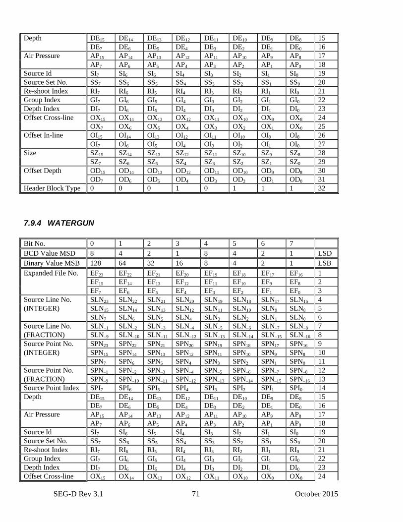
SEG-D Rev 3.1 71 October 2015
Depth DE15 DE14 DE13 DE12 DE11 DE10 DE9 DE8 15
DE7 DE6 DE5 DE4 DE3 DE2 DE1 DE0 16
Air Pressure AP15 AP14 AP13 AP12 AP11 AP10 AP9 AP8 17
AP7 AP6 AP5 AP4 AP3 AP2 AP1 AP0 18
Source Id SI7 SI6 SI5 SI4 SI3 SI2 SI1 SI0 19
Source Set No. SS7 SS6 SS5 SS4 SS3 SS2 SS1 SS0 20
Re-shoot Index RI7 RI6 RI5 RI4 RI3 RI2 RI1 RI0 21
Group Index GI7 GI6 GI5 GI4 GI3 GI2 GI1 GI0 22
Depth Index DI7 DI6 DI5 DI4 DI3 DI2 DI1 DI0 23
Offset Cross-line OX15 OX14 OX13 OX12 OX11 OX10 OX9 OX8 24
OX7 OX6 OX5 OX4 OX3 OX2 OX1 OX0 25
Offset In-line OI15 OI14 OI13 OI12 OI11 OI10 OI9 OI8 26
OI7 OI6 OI5 OI4 OI3 OI2 OI1 OI0 27
Size SZ15 SZ14 SZ13 SZ12 SZ11 SZ10 SZ9 SZ8 28
SZ7 SZ6 SZ5 SZ4 SZ3 SZ2 SZ1 SZ0 29
Offset Depth OD15 OD14 OD13 OD12 OD11 OD10 OD9 OD8 30
OD7 OD6 OD5 OD4 OD3 OD2 OD1 OD0 31
Header Block Type 0 0 0 1 0 1 1 1 32
7.9.4 WATERGUN
Bit No. 0 1 2 3 4 5 6 7
BCD Value MSD 8 4 2 1 8 4 2 1 LSD
Binary Value MSB 128 64 32 16 8 4 2 1 LSB
Expanded File No. EF23 EF22 EF21 EF20 EF19 EF18 EF17 EF16 1
EF15 EF14 EF13 EF12 EF11 EF10 EF9 EF8 2
EF7 EF6 EF5 EF4 EF3 EF2 EF1 EF0 3
Source Line No. SLN23 SLN22 SLN21 SLN20 SLN19 SLN18 SLN17 SLN16 4
(INTEGER) SLN15 SLN14 SLN13 SLN12 SLN11 SLN10 SLN9 SLN8 5
SLN7 SLN6 SLN5 SLN4 SLN3 SLN2 SLN1 SLN0 6
Source Line No. SLN–1 SLN–2 SLN–3 SLN–4 SLN–5 SLN–6 SLN–7 SLN–8 7
(FRACTION) SLN–9 SLN–10 SLN–11 SLN–12 SLN–13 SLN–14 SLN–15 SLN–16 8
Source Point No. SPN23 SPN22 SPN21 SPN20 SPN19 SPN18 SPN17 SPN16 9
(INTEGER) SPN15 SPN14 SPN13 SPN12 SPN11 SPN10 SPN9 SPN8 10
SPN7 SPN6 SPN5 SPN4 SPN3 SPN2 SPN1 SPN0 11
Source Point No. SPN–1 SPN–2 SPN–3 SPN–4 SPN–5 SPN–6 SPN–7 SPN–8 12
(FRACTION) SPN–9 SPN–10 SPN–11 SPN–12 SPN–13 SPN–14 SPN–15 SPN–16 13
Source Point Index SPI7 SPI6 SPI5 SPI4 SPI3 SPI2 SPI1 SPI0 14
Depth DE15 DE14 DE13 DE12 DE11 DE10 DE9 DE8 15
DE7 DE6 DE5 DE4 DE3 DE2 DE1 DE0 16
Air Pressure AP15 AP14 AP13 AP12 AP11 AP10 AP9 AP8 17
AP7 AP6 AP5 AP4 AP3 AP2 AP1 AP0 18
Source Id SI7 SI6 SI5 SI4 SI3 SI2 SI1 SI0 19
Source Set No. SS7 SS6 SS5 SS4 SS3 SS2 SS1 SS0 20
Re-shoot Index RI7 RI6 RI5 RI4 RI3 RI2 RI1 RI0 21
Group Index GI7 GI6 GI5 GI4 GI3 GI2 GI1 GI0 22
Depth Index DI7 DI6 DI5 DI4 DI3 DI2 DI1 DI0 23
Offset Cross-line OX15 OX14 OX13 OX12 OX11 OX10 OX9 OX8 24
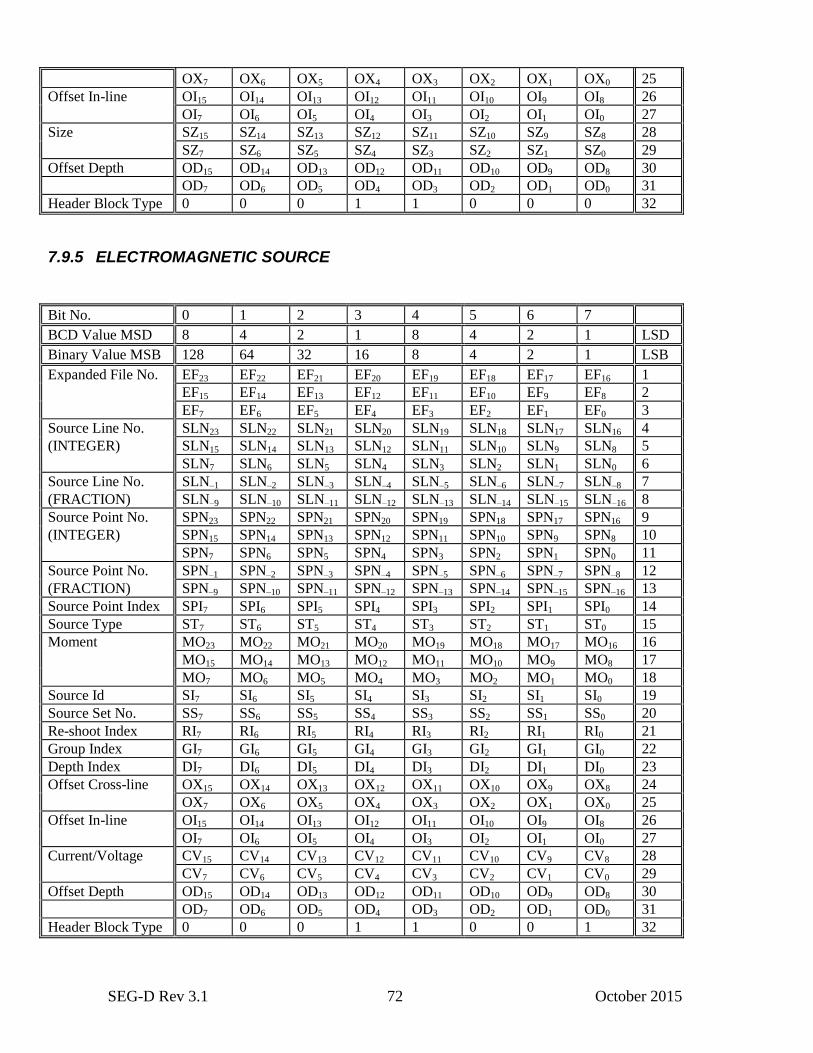
SEG-D Rev 3.1 72 October 2015
OX7 OX6 OX5 OX4 OX3 OX2 OX1 OX0 25
Offset In-line OI15 OI14 OI13 OI12 OI11 OI10 OI9 OI8 26
OI7 OI6 OI5 OI4 OI3 OI2 OI1 OI0 27
Size SZ15 SZ14 SZ13 SZ12 SZ11 SZ10 SZ9 SZ8 28
SZ7 SZ6 SZ5 SZ4 SZ3 SZ2 SZ1 SZ0 29
Offset Depth OD15 OD14 OD13 OD12 OD11 OD10 OD9 OD8 30
OD7 OD6 OD5 OD4 OD3 OD2 OD1 OD0 31
Header Block Type 0 0 0 1 1 0 0 0 32
7.9.5 ELECTROMAGNETIC SOURCE
Bit No. 0 1 2 3 4 5 6 7
BCD Value MSD 8 4 2 1 8 4 2 1 LSD
Binary Value MSB 128 64 32 16 8 4 2 1 LSB
Expanded File No. EF23 EF22 EF21 EF20 EF19 EF18 EF17 EF16 1
EF15 EF14 EF13 EF12 EF11 EF10 EF9 EF8 2
EF7 EF6 EF5 EF4 EF3 EF2 EF1 EF0 3
Source Line No. SLN23 SLN22 SLN21 SLN20 SLN19 SLN18 SLN17 SLN16 4
(INTEGER) SLN15 SLN14 SLN13 SLN12 SLN11 SLN10 SLN9 SLN8 5
SLN7 SLN6 SLN5 SLN4 SLN3 SLN2 SLN1 SLN0 6
Source Line No. SLN–1 SLN–2 SLN–3 SLN–4 SLN–5 SLN–6 SLN–7 SLN–8 7
(FRACTION) SLN–9 SLN–10 SLN–11 SLN–12 SLN–13 SLN–14 SLN–15 SLN–16 8
Source Point No. SPN23 SPN22 SPN21 SPN20 SPN19 SPN18 SPN17 SPN16 9
(INTEGER) SPN15 SPN14 SPN13 SPN12 SPN11 SPN10 SPN9 SPN8 10
SPN7 SPN6 SPN5 SPN4 SPN3 SPN2 SPN1 SPN0 11
Source Point No. SPN–1 SPN–2 SPN–3 SPN–4 SPN–5 SPN–6 SPN–7 SPN–8 12
(FRACTION) SPN–9 SPN–10 SPN–11 SPN–12 SPN–13 SPN–14 SPN–15 SPN–16 13
Source Point Index SPI7 SPI6 SPI5 SPI4 SPI3 SPI2 SPI1 SPI0 14
Source Type ST7 ST6 ST5 ST4 ST3 ST2 ST1 ST0 15
Moment MO23 MO22 MO21 MO20 MO19 MO18 MO17 MO16 16
MO15 MO14 MO13 MO12 MO11 MO10 MO9 MO8 17
MO7 MO6 MO5 MO4 MO3 MO2 MO1 MO0 18
Source Id SI7 SI6 SI5 SI4 SI3 SI2 SI1 SI0 19
Source Set No. SS7 SS6 SS5 SS4 SS3 SS2 SS1 SS0 20
Re-shoot Index RI7 RI6 RI5 RI4 RI3 RI2 RI1 RI0 21
Group Index GI7 GI6 GI5 GI4 GI3 GI2 GI1 GI0 22
Depth Index DI7 DI6 DI5 DI4 DI3 DI2 DI1 DI0 23
Offset Cross-line OX15 OX14 OX13 OX12 OX11 OX10 OX9 OX8 24
OX7 OX6 OX5 OX4 OX3 OX2 OX1 OX0 25
Offset In-line OI15 OI14 OI13 OI12 OI11 OI10 OI9 OI8 26
OI7 OI6 OI5 OI4 OI3 OI2 OI1 OI0 27
Current/Voltage CV15 CV14 CV13 CV12 CV11 CV10 CV9 CV8 28
CV7 CV6 CV5 CV4 CV3 CV2 CV1 CV0 29
Offset Depth OD15 OD14 OD13 OD12 OD11 OD10 OD9 OD8 30
OD7 OD6 OD5 OD4 OD3 OD2 OD1 OD0 31
Header Block Type 0 0 0 1 1 0 0 1 32
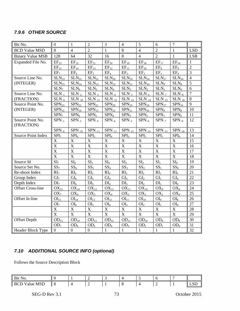
SEG-D Rev 3.1 73 October 2015
7.9.6 OTHER SOURCE
Bit No. 0 1 2 3 4 5 6 7
BCD Value MSD 8 4 2 1 8 4 2 1 LSD
Binary Value MSB 128 64 32 16 8 4 2 1 LSB
Expanded File No. EF23 EF22 EF21 EF20 EF19 EF18 EF17 EF16 1
EF15 EF14 EF13 EF12 EF11 EF10 EF9 EF8 2
EF7 EF6 EF5 EF4 EF3 EF2 EF1 EF0 3
Source Line No. SLN23 SLN22 SLN21 SLN20 SLN19 SLN18 SLN17 SLN16 4
(INTEGER) SLN15 SLN14 SLN13 SLN12 SLN11 SLN10 SLN9 SLN8 5
SLN7 SLN6 SLN5 SLN4 SLN3 SLN2 SLN1 SLN0 6
Source Line No. SLN–1 SLN–2 SLN–3 SLN–4 SLN–5 SLN–6 SLN–7 SLN–8 7
(FRACTION) SLN–9 SLN–10 SLN–11 SLN–12 SLN–13 SLN–14 SLN–15 SLN–16 8
Source Point No. SPN23 SPN22 SPN21 SPN20 SPN19 SPN18 SPN17 SPN16 9
(INTEGER) SPN15 SPN14 SPN13 SPN12 SPN11 SPN10 SPN9 SPN8 10
SPN7 SPN6 SPN5 SPN4 SPN3 SPN2 SPN1 SPN0 11
Source Point No.
(FRACTION)
SPN–1 SPN–2 SPN–3 SPN–4 SPN–5 SPN–6 SPN–7 SPN–8 12
SPN–9 SPN–10 SPN–11 SPN–12 SPN–13 SPN–14 SPN–15 SPN–16 13
Source Point Index SPI7 SPI6 SPI5 SPI4 SPI3 SPI2 SPI1 SPI0 14
X X X X X X X X 15
X X X X X X X X 16
X X X X X X X X 17
X X X X X X X X 18
Source Id SI7 SI6 SI5 SI4 SI3 SI2 SI1 SI0 19
Source Set No. SS7 SS6 SS5 SS4 SS3 SS2 SS1 SS0 20
Re-shoot Index RI7 RI6 RI5 RI4 RI3 RI2 RI1 RI0 21
Group Index GI7 GI6 GI5 GI4 GI3 GI2 GI1 GI0 22
Depth Index DI7 DI6 DI5 DI4 DI3 DI2 DI1 DI0 23
Offset Cross-line OX15 OX14 OX13 OX12 OX11 OX10 OX9 OX8 24
OX7 OX6 OX5 OX4 OX3 OX2 OX1 OX0 25
Offset In-line OI15 OI14 OI13 OI12 OI11 OI10 OI9 OI8 26
OI7 OI6 OI5 OI4 OI3 OI2 OI1 OI0 27
X X X X X X X X 28
X X X X X X X X 29
Offset Depth OD15 OD14 OD13 OD12 OD11 OD10 OD9 OD8 30
OD7 OD6 OD5 OD4 OD3 OD2 OD1 OD0 31
Header Block Type 0 0 0 1 1 1 1 1 32
7.10 ADDITIONAL SOURCE INFO (optional)
Follows the Source Description Block
Bit No. 0 1 2 3 4 5 6 7
BCD Value MSD 8 4 2 1 8 4 2 1 LSD
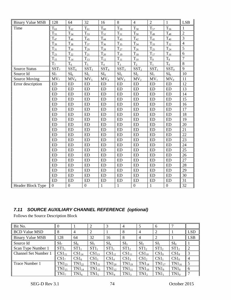
SEG-D Rev 3.1 74 October 2015
Binary Value MSB 128 64 32 16 8 4 2 1 LSB
Time T63 T62 T61 T60 T59 T58 T57 T56 1
T55 T54 T53 T52 T51 T50 T49 T48 2
T47 T46 T45 T44 T43 T42 T41 T40 3
T39 T38 T37 T36 T35 T34 T33 T32 4
T31 T30 T29 T28 T27 T26 T25 T24 5
T23 T22 T21 T20 T19 T18 T17 T16 6
T15 T14 T13 T12 T11 T10 T9 T8 7
T7 T6 T5 T4 T3 T2 T1 T0 8
Source Status SST7 SST6 SST5 SST4 SST3 SST2 SST1 SST0 9
Source Id SI7 SI6 SI5 SI4 SI3 SI2 SI1 SI0 10
Source Moving MV7 MV6 MV5 MV4 MV3 MV2 MV1 MV0 11
Error description ED ED ED ED ED ED ED ED 12
ED ED ED ED ED ED ED ED 13
ED ED ED ED ED ED ED ED 14
ED ED ED ED ED ED ED ED 15
ED ED ED ED ED ED ED ED 16
ED ED ED ED ED ED ED ED 17
ED ED ED ED ED ED ED ED 18
ED ED ED ED ED ED ED ED 19
ED ED ED ED ED ED ED ED 20
ED ED ED ED ED ED ED ED 21
ED ED ED ED ED ED ED ED 22
ED ED ED ED ED ED ED ED 23
ED ED ED ED ED ED ED ED 24
ED ED ED ED ED ED ED ED 25
ED ED ED ED ED ED ED ED 26
ED ED ED ED ED ED ED ED 27
ED ED ED ED ED ED ED ED 28
ED ED ED ED ED ED ED ED 29
ED ED ED ED ED ED ED ED 30
ED ED ED ED ED ED ED ED 31
Header Block Type 0 0 0 1 1 0 1 0 32
7.11 SOURCE AUXILIARY CHANNEL REFERENCE (optional)
Follows the Source Description Block
Bit No. 0 1 2 3 4 5 6 7
BCD Value MSD 8 4 2 1 8 4 2 1 LSD
Binary Value MSB 128 64 32 16 8 4 2 1 LSB
Source Id SI7 SI6 SI5 SI4 SI3 SI2 SI1 SI0 1
Scan Type Number 1 ST11 ST11 ST11 ST11 ST12 ST12 ST12 ST12 2
Channel Set Number 1 CS115 CS114 CS113 CS112 CS111 CS110 CS19 CS18 3
CS17 CS16 CS15 CS14 CS13 CS12 CS11 CS10 4
Trace Number 1 TN123 TN122 TN121 TN120 TN119 TN118 TN117 TN116 5
TN115 TN114 TN113 TN112 TN111 TN110 TN19 TN18 6
TN17 TN16 TN15 TN14 TN13 TN12 TN11 TN10 7
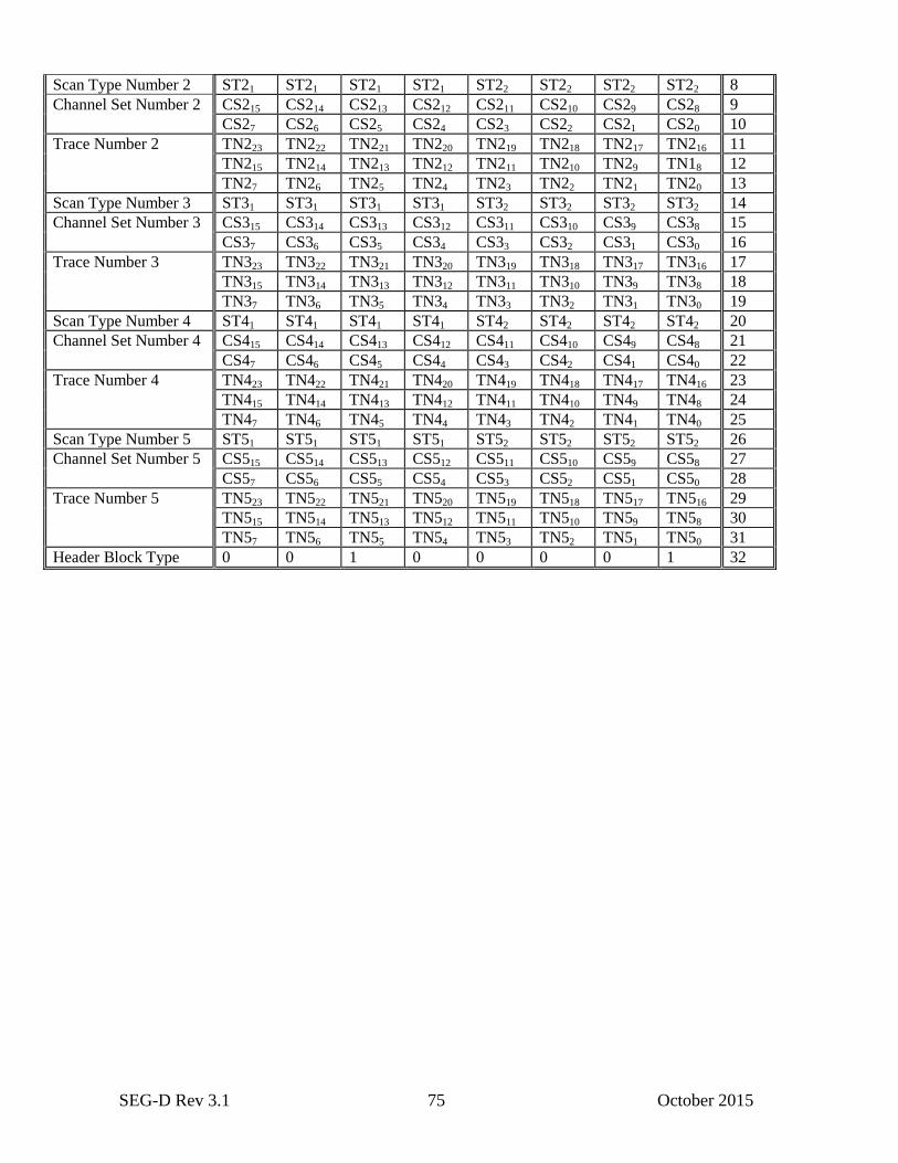
SEG-D Rev 3.1 75 October 2015
Scan Type Number 2 ST21 ST21 ST21 ST21 ST22 ST22 ST22 ST22 8
Channel Set Number 2 CS215 CS214 CS213 CS212 CS211 CS210 CS29 CS28 9
CS27 CS26 CS25 CS24 CS23 CS22 CS21 CS20 10
Trace Number 2 TN223 TN222 TN221 TN220 TN219 TN218 TN217 TN216 11
TN215 TN214 TN213 TN212 TN211 TN210 TN29 TN18 12
TN27 TN26 TN25 TN24 TN23 TN22 TN21 TN20 13
Scan Type Number 3 ST31 ST31 ST31 ST31 ST32 ST32 ST32 ST32 14
Channel Set Number 3 CS315 CS314 CS313 CS312 CS311 CS310 CS39 CS38 15
CS37 CS36 CS35 CS34 CS33 CS32 CS31 CS30 16
Trace Number 3 TN323 TN322 TN321 TN320 TN319 TN318 TN317 TN316 17
TN315 TN314 TN313 TN312 TN311 TN310 TN39 TN38 18
TN37 TN36 TN35 TN34 TN33 TN32 TN31 TN30 19
Scan Type Number 4 ST41 ST41 ST41 ST41 ST42 ST42 ST42 ST42 20
Channel Set Number 4 CS415 CS414 CS413 CS412 CS411 CS410 CS49 CS48 21
CS47 CS46 CS45 CS44 CS43 CS42 CS41 CS40 22
Trace Number 4 TN423 TN422 TN421 TN420 TN419 TN418 TN417 TN416 23
TN415 TN414 TN413 TN412 TN411 TN410 TN49 TN48 24
TN47 TN46 TN45 TN44 TN43 TN42 TN41 TN40 25
Scan Type Number 5 ST51 ST51 ST51 ST51 ST52 ST52 ST52 ST52 26
Channel Set Number 5 CS515 CS514 CS513 CS512 CS511 CS510 CS59 CS58 27
CS57 CS56 CS55 CS54 CS53 CS52 CS51 CS50 28
Trace Number 5 TN523 TN522 TN521 TN520 TN519 TN518 TN517 TN516 29
TN515 TN514 TN513 TN512 TN511 TN510 TN59 TN58 30
TN57 TN56 TN55 TN54 TN53 TN52 TN51 TN50 31
Header Block Type 0 0 1 0 0 0 0 1 32
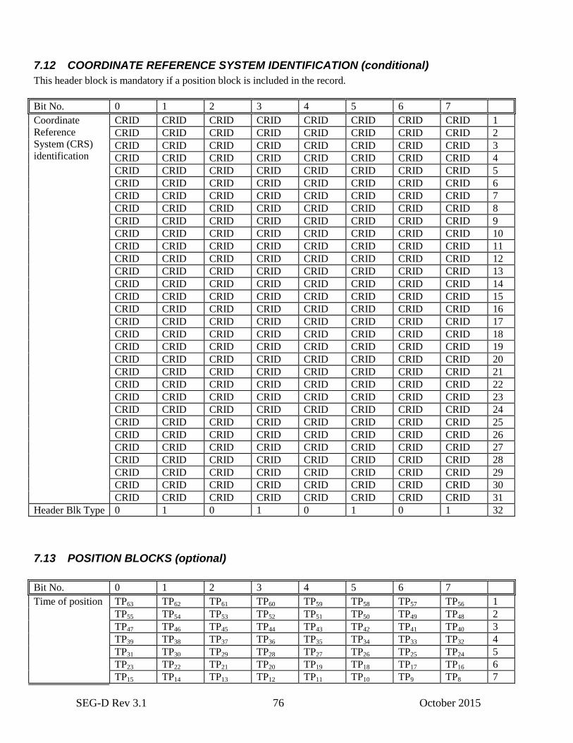
SEG-D Rev 3.1 76 October 2015
7.12 COORDINATE REFERENCE SYSTEM IDENTIFICATION (conditional)
This header block is mandatory if a position block is included in the record.
Bit No. 0 1 2 3 4 5 6 7
Coordinate
Reference
System (CRS)
identification
CRID CRID CRID CRID CRID CRID CRID CRID 1
CRID CRID CRID CRID CRID CRID CRID CRID 2
CRID CRID CRID CRID CRID CRID CRID CRID 3
CRID CRID CRID CRID CRID CRID CRID CRID 4
CRID CRID CRID CRID CRID CRID CRID CRID 5
CRID CRID CRID CRID CRID CRID CRID CRID 6
CRID CRID CRID CRID CRID CRID CRID CRID 7
CRID CRID CRID CRID CRID CRID CRID CRID 8
CRID CRID CRID CRID CRID CRID CRID CRID 9
CRID CRID CRID CRID CRID CRID CRID CRID 10
CRID CRID CRID CRID CRID CRID CRID CRID 11
CRID CRID CRID CRID CRID CRID CRID CRID 12
CRID CRID CRID CRID CRID CRID CRID CRID 13
CRID CRID CRID CRID CRID CRID CRID CRID 14
CRID CRID CRID CRID CRID CRID CRID CRID 15
CRID CRID CRID CRID CRID CRID CRID CRID 16
CRID CRID CRID CRID CRID CRID CRID CRID 17
CRID CRID CRID CRID CRID CRID CRID CRID 18
CRID CRID CRID CRID CRID CRID CRID CRID 19
CRID CRID CRID CRID CRID CRID CRID CRID 20
CRID CRID CRID CRID CRID CRID CRID CRID 21
CRID CRID CRID CRID CRID CRID CRID CRID 22
CRID CRID CRID CRID CRID CRID CRID CRID 23
CRID CRID CRID CRID CRID CRID CRID CRID 24
CRID CRID CRID CRID CRID CRID CRID CRID 25
CRID CRID CRID CRID CRID CRID CRID CRID 26
CRID CRID CRID CRID CRID CRID CRID CRID 27
CRID CRID CRID CRID CRID CRID CRID CRID 28
CRID CRID CRID CRID CRID CRID CRID CRID 29
CRID CRID CRID CRID CRID CRID CRID CRID 30
CRID CRID CRID CRID CRID CRID CRID CRID 31
Header Blk Type 0 1 0 1 0 1 0 1 32
7.13 POSITION BLOCKS (optional)
Bit No. 0 1 2 3 4 5 6 7
Time of position TP63 TP62 TP61 TP60 TP59 TP58 TP57 TP56 1
TP55 TP54 TP53 TP52 TP51 TP50 TP49 TP48 2
TP47 TP46 TP45 TP44 TP43 TP42 TP41 TP40 3
TP39 TP38 TP37 TP36 TP35 TP34 TP33 TP32 4
TP31 TP30 TP29 TP28 TP27 TP26 TP25 TP24 5
TP23 TP22 TP21 TP20 TP19 TP18 TP17 TP16 6
TP15 TP14 TP13 TP12 TP11 TP10 TP9 TP8 7
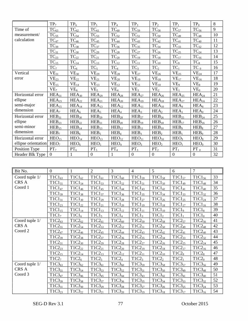
SEG-D Rev 3.1 77 October 2015
TP7 TP6 TP5 TP4 TP3 TP2 TP1 TP0 8
Time of
measurement/
calculation
TC63 TC62 TC61 TC60 TC59 TC58 TC57 TC56 9
TC55 TC54 TC53 TC52 TC51 TC50 TC49 TC48 10
TC47 TC46 TC45 TC44 TC43 TC42 TC41 TC40 11
TC39 TC38 TC37 TC36 TC35 TC34 TC33 TC32 12
TC31 TC30 TC29 TC28 TC27 TC26 TC25 TC24 13
TC23 TC22 TC21 TC20 TC19 TC18 TC17 TC16 14
TC15 TC14 TC13 TC12 TC11 TC10 TC9 TC8 15
TC7 TC6 TC5 TC4 TC3 TC2 TC1 TC 0 16
Vertical
error
VE31 VE30 VE29 VE28 VE27 VE26 VE25 VE24 17
VE23 VE22 VE21 VE20 VE19 VE18 VE17 VE16 18
VE15 VE14 VE13 VE12 VE11 VE10 VE9 VE8 19
VE7 VE6 VE5 VE4 VE3 VE2 VE1 VE0 20
Horizontal error
ellipse
semi-major
dimension
HEA31 HEA30 HEA29 HEA28 HEA27 HEA26 HEA25 HEA24 21
HEA23 HEA22 HEA21 HEA20 HEA19 HEA18 HEA17 HEA16 22
HEA15 HEA14 HEA13 HEA12 HEA11 HEA10 HEA9 HEA8 23
HEA7 HEA6 HEA5 HEA4 HEA3 HEA2 HEA1 HEA0 24
Horizontal error
ellipse
semi-minor
dimension
HEB31 HEB30 HEB29 HEB28 HEB27 HEB26 HEB25 HEB24 25
HEB23 HEB22 HEB21 HEB20 HEB19 HEB18 HEB17 HEB16 26
HEB15 HEB14 HEB13 HEB12 HEB11 HEB10 HEB9 HEB8 27
HEB7 HEB6 HEB5 HEB4 HEB3 HEB2 HEB1 HEB0 28
Horizontal error
ellipse orientation
HEO15 HEO14 HEO13 HEO12 HEO11 HEO10 HEO9 HEO8 29
HEO7 HEO6 HEO5 HEO4 HEO3 HEO2 HEO1 HEO0 30
Position Type PT7 PT6 PT5 PT4 PT3 PT2 PT1 PT 0 31
Header Blk Type 0 1 0 1 0 0 0 0 32
Bit No. 0 1 2 3 4 5 6 7
Coord tuple 1/
CRS A
Coord 1
T1C163 T1C162 T1C161 T1C160 T1C159 T1C158 T1C157 T1C156 33
T1C155 T1C154 T1C153 T1C152 T1C151 T1C150 T1C149 T1C148 34
T1C147 T1C146 T1C145 T1C144 T1C143 T1C142 T1C141 T1C140 35
T1C139 T1C138 T1C137 T1C136 T1C135 T1C134 T1C133 T1C132 36
T1C131 T1C130 T1C129 T1C128 T1C127 T1C126 T1C125 T1C124 37
T1C123 T1C122 T1C121 T1C120 T1C119 T1C118 T1C117 T1C116 38
T1C115 T1C114 T1C113 T1C112 T1C111 T1C110 T1C19 T1C18 39
T1C17 T1C16 T1C15 T1C14 T1C13 T1C12 T1C11 T1C10 40
Coord tuple 1/
CRS A
Coord 2
T1C263 T1C262 T1C261 T1C260 T1C259 T1C258 T1C257 T1C256 41
T1C255 T1C254 T1C253 T1C252 T1C251 T1C250 T1C249 T1C248 42
T1C247 T1C246 T1C245 T1C244 T1C243 T1C242 T1C241 T1C240 43
T1C239 T1C238 T1C237 T1C236 T1C235 T1C234 T1C233 T1C232 44
T1C231 T1C230 T1C229 T1C228 T1C227 T1C226 T1C225 T1C224 45
T1C223 T1C222 T1C221 T1C220 T1C219 T1C218 T1C217 T1C216 46
T1C215 T1C214 T1C213 T1C212 T1C211 T1C210 T1C29 T1C28 47
T1C27 T1C26 T1C25 T1C24 T1C23 T1C22 T1C21 T1C20 48
Coord tuple 1/
CRS A
Coord 3
T1C363 T1C362 T1C361 T1C360 T1C359 T1C358 T1C357 T1C356 49
T1C355 T1C354 T1C353 T1C352 T1C351 T1C350 T1C349 T1C348 50
T1C347 T1C346 T1C345 T1C344 T1C343 T1C342 T1C341 T1C340 51
T1C339 T1C338 T1C337 T1C336 T1C335 T1C334 T1C333 T1C332 52
T1C331 T1C330 T1C329 T1C328 T1C327 T1C326 T1C325 T1C324 53
T1C323 T1C322 T1C321 T1C320 T1C319 T1C318 T1C317 T1C316 54
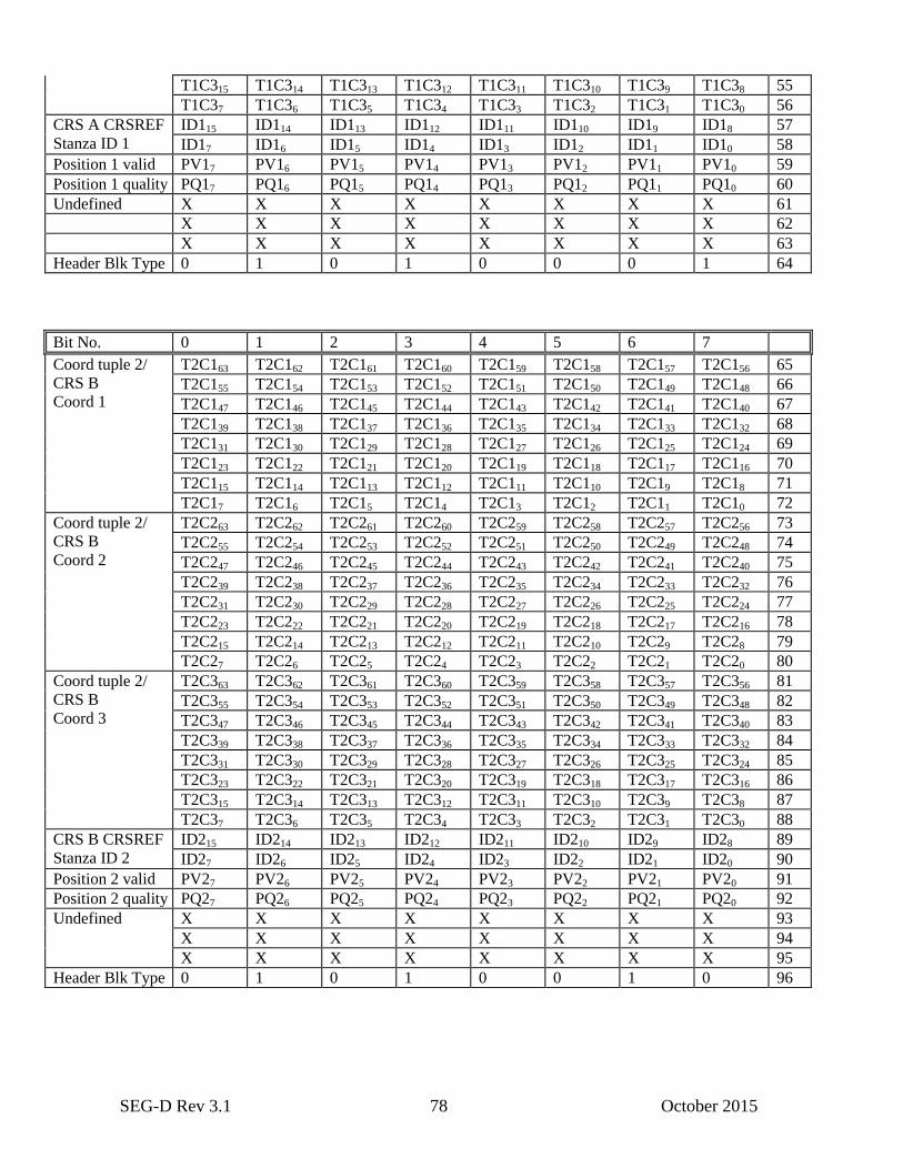
SEG-D Rev 3.1 78 October 2015
T1C315 T1C314 T1C313 T1C312 T1C311 T1C310 T1C39 T1C38 55
T1C37 T1C36 T1C35 T1C34 T1C33 T1C32 T1C31 T1C30 56
CRS A CRSREF
Stanza ID 1
ID115 ID114 ID113 ID112 ID111 ID110 ID19 ID18 57
ID17 ID16 ID15 ID14 ID13 ID12 ID11 ID10 58
Position 1 valid PV17 PV16 PV15 PV14 PV13 PV12 PV11 PV10 59
Position 1 quality PQ17 PQ16 PQ15 PQ14 PQ13 PQ12 PQ11 PQ10 60
Undefined X X X X X X X X 61
X X X X X X X X 62
X X X X X X X X 63
Header Blk Type 0 1 0 1 0 0 0 1 64
Bit No. 0 1 2 3 4 5 6 7
Coord tuple 2/
CRS B
Coord 1
T2C163 T2C162 T2C161 T2C160 T2C159 T2C158 T2C157 T2C156 65
T2C155 T2C154 T2C153 T2C152 T2C151 T2C150 T2C149 T2C148 66
T2C147 T2C146 T2C145 T2C144 T2C143 T2C142 T2C141 T2C140 67
T2C139 T2C138 T2C137 T2C136 T2C135 T2C134 T2C133 T2C132 68
T2C131 T2C130 T2C129 T2C128 T2C127 T2C126 T2C125 T2C124 69
T2C123 T2C122 T2C121 T2C120 T2C119 T2C118 T2C117 T2C116 70
T2C115 T2C114 T2C113 T2C112 T2C111 T2C110 T2C19 T2C18 71
T2C17 T2C16 T2C15 T2C14 T2C13 T2C12 T2C11 T2C10 72
Coord tuple 2/
CRS B
Coord 2
T2C263 T2C262 T2C261 T2C260 T2C259 T2C258 T2C257 T2C256 73
T2C255 T2C254 T2C253 T2C252 T2C251 T2C250 T2C249 T2C248 74
T2C247 T2C246 T2C245 T2C244 T2C243 T2C242 T2C241 T2C240 75
T2C239 T2C238 T2C237 T2C236 T2C235 T2C234 T2C233 T2C232 76
T2C231 T2C230 T2C229 T2C228 T2C227 T2C226 T2C225 T2C224 77
T2C223 T2C222 T2C221 T2C220 T2C219 T2C218 T2C217 T2C216 78
T2C215 T2C214 T2C213 T2C212 T2C211 T2C210 T2C29 T2C28 79
T2C27 T2C26 T2C25 T2C24 T2C23 T2C22 T2C21 T2C20 80
Coord tuple 2/
CRS B
Coord 3
T2C363 T2C362 T2C361 T2C360 T2C359 T2C358 T2C357 T2C356 81
T2C355 T2C354 T2C353 T2C352 T2C351 T2C350 T2C349 T2C348 82
T2C347 T2C346 T2C345 T2C344 T2C343 T2C342 T2C341 T2C340 83
T2C339 T2C338 T2C337 T2C336 T2C335 T2C334 T2C333 T2C332 84
T2C331 T2C330 T2C329 T2C328 T2C327 T2C326 T2C325 T2C324 85
T2C323 T2C322 T2C321 T2C320 T2C319 T2C318 T2C317 T2C316 86
T2C315 T2C314 T2C313 T2C312 T2C311 T2C310 T2C39 T2C38 87
T2C37 T2C36 T2C35 T2C34 T2C33 T2C32 T2C31 T2C30 88
CRS B CRSREF
Stanza ID 2
ID215 ID214 ID213 ID212 ID211 ID210 ID29 ID28 89
ID27 ID26 ID25 ID24 ID23 ID22 ID21 ID20 90
Position 2 valid PV27 PV26 PV25 PV24 PV23 PV22 PV21 PV20 91
Position 2 quality PQ27 PQ26 PQ25 PQ24 PQ23 PQ22 PQ21 PQ20 92
Undefined X X X X X X X X 93
X X X X X X X X 94
X X X X X X X X 95
Header Blk Type 0 1 0 1 0 0 1 0 96
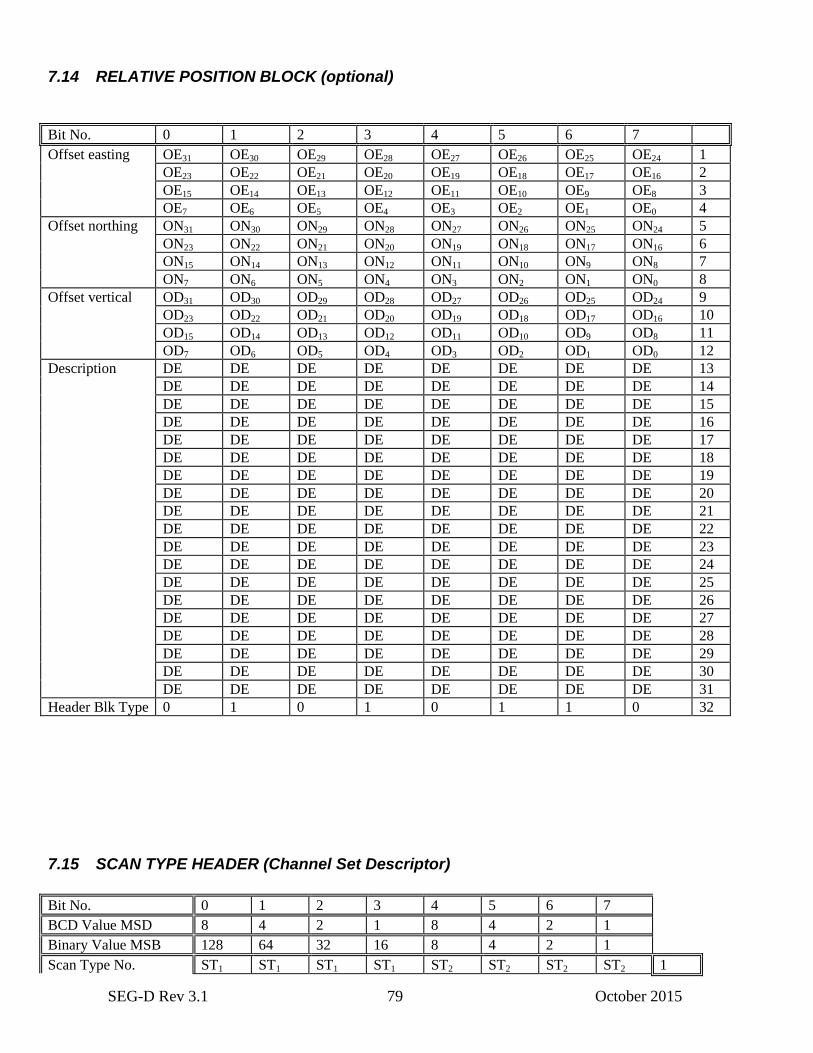
SEG-D Rev 3.1 79 October 2015
7.14 RELATIVE POSITION BLOCK (optional)
Bit No. 0 1 2 3 4 5 6 7
Offset easting OE31 OE30 OE29 OE28 OE27 OE26 OE25 OE24 1
OE23 OE22 OE21 OE20 OE19 OE18 OE17 OE16 2
OE15 OE14 OE13 OE12 OE11 OE10 OE9 OE8 3
OE7 OE6 OE5 OE4 OE3 OE2 OE1 OE0 4
Offset northing ON31 ON30 ON29 ON28 ON27 ON26 ON25 ON24 5
ON23 ON22 ON21 ON20 ON19 ON18 ON17 ON16 6
ON15 ON14 ON13 ON12 ON11 ON10 ON9 ON8 7
ON7 ON6 ON5 ON4 ON3 ON2 ON1 ON0 8
Offset vertical OD31 OD30 OD29 OD28 OD27 OD26 OD25 OD24 9
OD23 OD22 OD21 OD20 OD19 OD18 OD17 OD16 10
OD15 OD14 OD13 OD12 OD11 OD10 OD9 OD8 11
OD7 OD6 OD5 OD4 OD3 OD2 OD1 OD0 12
Description DE DE DE DE DE DE DE DE 13
DE DE DE DE DE DE DE DE 14
DE DE DE DE DE DE DE DE 15
DE DE DE DE DE DE DE DE 16
DE DE DE DE DE DE DE DE 17
DE DE DE DE DE DE DE DE 18
DE DE DE DE DE DE DE DE 19
DE DE DE DE DE DE DE DE 20
DE DE DE DE DE DE DE DE 21
DE DE DE DE DE DE DE DE 22
DE DE DE DE DE DE DE DE 23
DE DE DE DE DE DE DE DE 24
DE DE DE DE DE DE DE DE 25
DE DE DE DE DE DE DE DE 26
DE DE DE DE DE DE DE DE 27
DE DE DE DE DE DE DE DE 28
DE DE DE DE DE DE DE DE 29
DE DE DE DE DE DE DE DE 30
DE DE DE DE DE DE DE DE 31
Header Blk Type 0 1 0 1 0 1 1 0 32
7.15 SCAN TYPE HEADER (Channel Set Descriptor)
Bit No. 0 1 2 3 4 5 6 7
BCD Value MSD 8 4 2 1 8 4 2 1
Binary Value MSB 128 64 32 16 8 4 2 1
Scan Type No. ST1 ST1 ST1 ST1 ST2 ST2 ST2 ST2 1
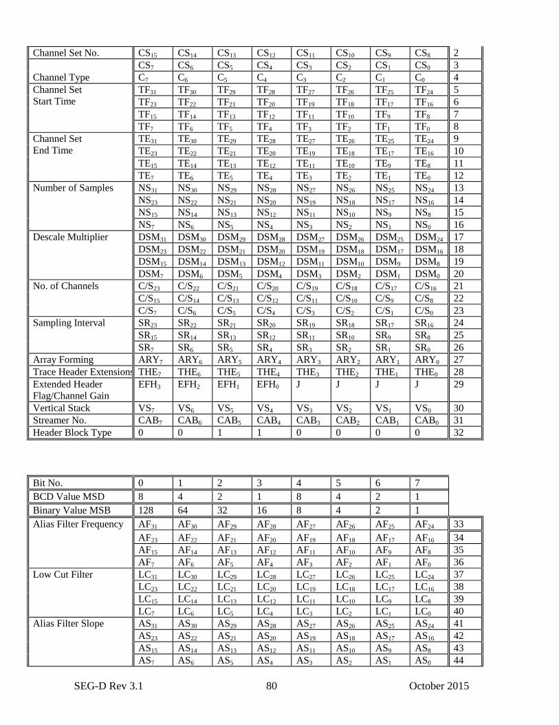
SEG-D Rev 3.1 80 October 2015
Channel Set No. CS15 CS14 CS13 CS12 CS11 CS10 CS9 CS8 2
CS7 CS6 CS5 CS4 CS3 CS2 CS1 CS0 3
Channel Type C7 C6 C5 C4 C3 C2 C1 C0 4
Channel Set
Start Time
TF31 TF30 TF29 TF28 TF27 TF26 TF25 TF24 5
TF23 TF22 TF21 TF20 TF19 TF18 TF17 TF16 6
TF15 TF14 TF13 TF12 TF11 TF10 TF9 TF8 7
TF7 TF6 TF5 TF4 TF3 TF2 TF1 TF0 8
Channel Set
End Time
TE31 TE30 TE29 TE28 TE27 TE26 TE25 TE24 9
TE23 TE22 TE21 TE20 TE19 TE18 TE17 TE16 10
TE15 TE14 TE13 TE12 TE11 TE10 TE9 TE8 11
TE7 TE6 TE5 TE4 TE3 TE2 TE1 TE0 12
Number of Samples NS31 NS30 NS29 NS28 NS27 NS26 NS25 NS24 13
NS23 NS22 NS21 NS20 NS19 NS18 NS17 NS16 14
NS15 NS14 NS13 NS12 NS11 NS10 NS9 NS8 15
NS7 NS6 NS5 NS4 NS3 NS2 NS1 NS0 16
Descale Multiplier DSM31 DSM30 DSM29 DSM28 DSM27 DSM26 DSM25 DSM24 17
DSM23 DSM22 DSM21 DSM20 DSM19 DSM18 DSM17 DSM16 18
DSM15 DSM14 DSM13 DSM12 DSM11 DSM10 DSM9 DSM8 19
DSM7 DSM6 DSM5 DSM4 DSM3 DSM2 DSM1 DSM0 20
No. of Channels C/S23 C/S22 C/S21 C/S20 C/S19 C/S18 C/S17 C/S16 21
C/S15 C/S14 C/S13 C/S12 C/S11 C/S10 C/S9 C/S8 22
C/S7 C/S6 C/S5 C/S4 C/S3 C/S2 C/S1 C/S0 23
Sampling Interval SR23 SR22 SR21 SR20 SR19 SR18 SR17 SR16 24
SR15 SR14 SR13 SR12 SR11 SR10 SR9 SR8 25
SR7 SR6 SR5 SR4 SR3 SR2 SR1 SR0 26
Array Forming ARY7 ARY6 ARY5 ARY4 ARY3 ARY2 ARY1 ARY0 27
Trace Header Extensions THE7 THE6 THE5 THE4 THE3 THE2 THE1 THE0 28
Extended Header
Flag/Channel Gain
EFH3 EFH2 EFH1 EFH0 J J J J 29
Vertical Stack VS7 VS6 VS5 VS4 VS3 VS2 VS1 VS0 30
Streamer No. CAB7 CAB6 CAB5 CAB4 CAB3 CAB2 CAB1 CAB0 31
Header Block Type 0 0 1 1 0 0 0 0 32
Bit No. 0 1 2 3 4 5 6 7
BCD Value MSD 8 4 2 1 8 4 2 1
Binary Value MSB 128 64 32 16 8 4 2 1
Alias Filter Frequency AF31 AF30 AF29 AF28 AF27 AF26 AF25 AF24 33
AF23 AF22 AF21 AF20 AF19 AF18 AF17 AF16 34
AF15 AF14 AF13 AF12 AF11 AF10 AF9 AF8 35
AF7 AF6 AF5 AF4 AF3 AF2 AF1 AF0 36
Low Cut Filter LC31 LC30 LC29 LC28 LC27 LC26 LC25 LC24 37
LC23 LC22 LC21 LC20 LC19 LC18 LC17 LC16 38
LC15 LC14 LC13 LC12 LC11 LC10 LC9 LC8 39
LC7 LC6 LC5 LC4 LC3 LC2 LC1 LC0 40
Alias Filter Slope AS31 AS30 AS29 AS28 AS27 AS26 AS25 AS24 41
AS23 AS22 AS21 AS20 AS19 AS18 AS17 AS16 42
AS15 AS14 AS13 AS12 AS11 AS10 AS9 AS8 43
AS7 AS6 AS5 AS4 AS3 AS2 AS1 AS0 44
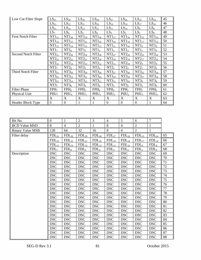
SEG-D Rev 3.1 81 October 2015
Low Cut Filter Slope LS31 LS30 LS29 LS28 LS27 LS26 LS25 LS24 45
LS23 LS22 LS21 LS20 LS19 LS18 LS17 LS16 46
LS15 LS14 LS13 LS12 LS11 LS10 LS9 LS8 47
LS7 LS6 LS5 LS4 LS3 LS2 LS1 LS0 48
First Notch Filter NT131 NT130 NT129 NT128 NT127 NT126 NT125 NT124 49
NT123 NT122 NT121 NT120 NT119 NT118 NT117 NT116 50
NT115 NT114 NT113 NT112 NT111 NT110 NT19 NT18 51
NT17 NT16 NT15 NT14 NT13 NT12 NT11 NT10 52
Second Notch Filter NT231 NT230 NT229 NT228 NT227 NT226 NT225 NT224 53
NT223 NT222 NT221 NT220 NT219 NT218 NT217 NT216 54
NT215 NT214 NT213 NT212 NT211 NT210 NT29 NT28 55
NT27 NT26 NT25 NT24 NT23 NT22 NT21 NT20 56
Third Notch Filter NT331 NT330 NT329 NT328 NT327 NT326 NT325 NT324 57
NT323 NT322 NT321 NT320 NT319 NT318 NT317 NT316 58
NT315 NT314 NT313 NT312 NT311 NT310 NT39 NT38 59
NT37 NT36 NT35 NT34 NT33 NT32 NT31 NT30 60
Filter Phase FPH7 FPH6 FPH5 FPH4 FPH3 FPH2 FPH1 FPH0 61
Physical Unit PHU7 PHU6 PHU5 PHU4 PHU3 PHU2 PHU1 PHU0 62
X X X X X X X X 63
Header Block Type 0 0 1 1 0 0 0 1 64
Bit No. 0 1 2 3 4 5 6 7
BCD Value MSD 8 4 2 1 8 4 2 1
Binary Value MSB 128 64 32 16 8 4 2 1
Filter delay FDL31 FDL30 FDL29 FDL28 FDL27 FDL26 FDL25 FDL24 65
FDL23 FDL22 FDL21 FDL20 FDL19 FDL18 FDL17 FDL16 66
FDL15 FDL14 FDL13 FDL12 FDL11 FDL10 FDL9 FDL8 67
FDL7 FDL6 FDL5 FDL4 FDL3 FDL2 FDL1 FDL0 68
Description DSC DSC DSC DSC DSC DSC DSC DSC 69
DSC DSC DSC DSC DSC DSC DSC DSC 70
DSC DSC DSC DSC DSC DSC DSC DSC 71
DSC DSC DSC DSC DSC DSC DSC DSC 72
DSC DSC DSC DSC DSC DSC DSC DSC 73
DSC DSC DSC DSC DSC DSC DSC DSC 74
DSC DSC DSC DSC DSC DSC DSC DSC 75
DSC DSC DSC DSC DSC DSC DSC DSC 76
DSC DSC DSC DSC DSC DSC DSC DSC 77
DSC DSC DSC DSC DSC DSC DSC DSC 78
DSC DSC DSC DSC DSC DSC DSC DSC 79
DSC DSC DSC DSC DSC DSC DSC DSC 80
DSC DSC DSC DSC DSC DSC DSC DSC 81
DSC DSC DSC DSC DSC DSC DSC DSC 82
DSC DSC DSC DSC DSC DSC DSC DSC 83
DSC DSC DSC DSC DSC DSC DSC DSC 84
DSC DSC DSC DSC DSC DSC DSC DSC 85
DSC DSC DSC DSC DSC DSC DSC DSC 86
DSC DSC DSC DSC DSC DSC DSC DSC 87
DSC DSC DSC DSC DSC DSC DSC DSC 88
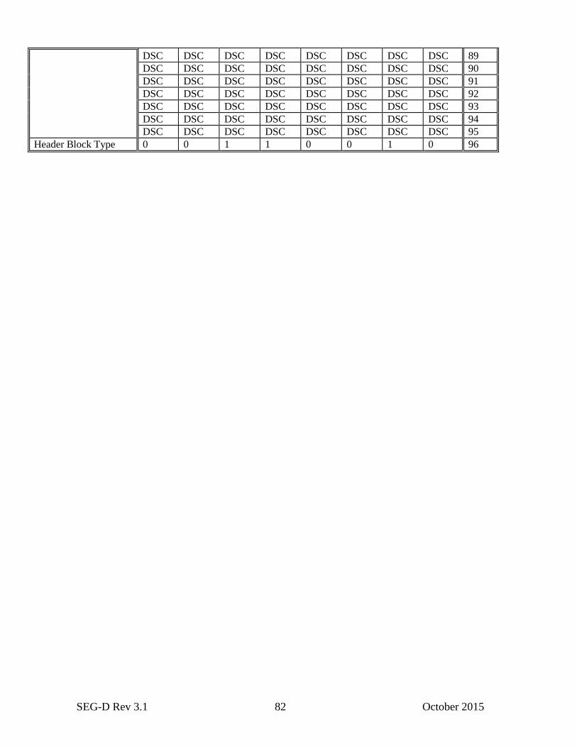
SEG-D Rev 3.1 82 October 2015
DSC DSC DSC DSC DSC DSC DSC DSC 89
DSC DSC DSC DSC DSC DSC DSC DSC 90
DSC DSC DSC DSC DSC DSC DSC DSC 91
DSC DSC DSC DSC DSC DSC DSC DSC 92
DSC DSC DSC DSC DSC DSC DSC DSC 93
DSC DSC DSC DSC DSC DSC DSC DSC 94
DSC DSC DSC DSC DSC DSC DSC DSC 95
Header Block Type 0 0 1 1 0 0 1 0 96
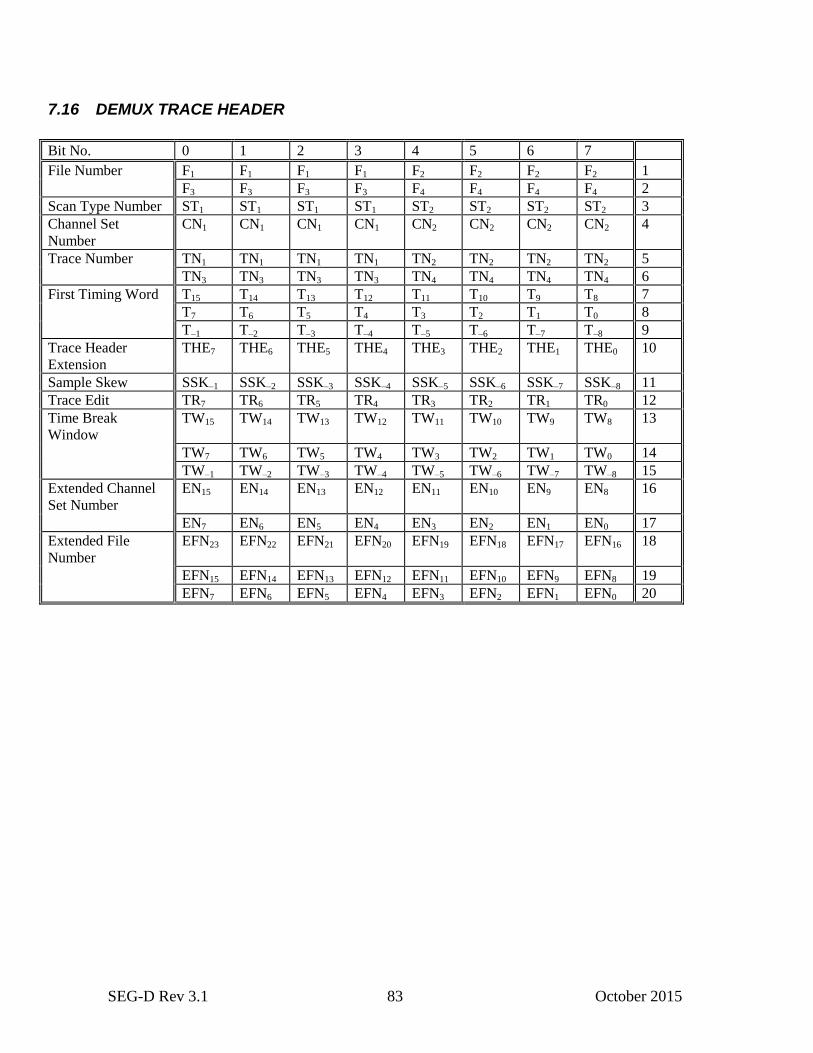
SEG-D Rev 3.1 83 October 2015
7.16 DEMUX TRACE HEADER
Bit No. 0 1 2 3 4 5 6 7
File Number F1 F1 F1 F1 F2 F2 F2 F2 1
F3 F3 F3 F3 F4 F4 F4 F4 2
Scan Type Number ST1 ST1 ST1 ST1 ST2 ST2 ST2 ST2 3
Channel Set
Number
CN1 CN1 CN1 CN1 CN2 CN2 CN2 CN2 4
Trace Number TN1 TN1 TN1 TN1 TN2 TN2 TN2 TN2 5
TN3 TN3 TN3 TN3 TN4 TN4 TN4 TN4 6
First Timing Word T15 T14 T13 T12 T11 T10 T9 T8 7
T7 T6 T5 T4 T3 T2 T1 T0 8
T–1 T–2 T–3 T–4 T–5 T–6 T–7 T–8 9
Trace Header
Extension
THE7 THE6 THE5 THE4 THE3 THE2 THE1 THE0 10
Sample Skew SSK–1 SSK–2 SSK–3 SSK–4 SSK–5 SSK–6 SSK–7 SSK–8 11
Trace Edit TR7 TR6 TR5 TR4 TR3 TR2 TR1 TR0 12
Time Break
Window
TW15 TW14 TW13 TW12 TW11 TW10 TW9 TW8 13
TW7 TW6 TW5 TW4 TW3 TW2 TW1 TW0 14
TW–1 TW–2 TW–3 TW–4 TW–5 TW–6 TW–7 TW–8 15
Extended Channel
Set Number
EN15 EN14 EN13 EN12 EN11 EN10 EN9 EN8 16
EN7 EN6 EN5 EN4 EN3 EN2 EN1 EN0 17
Extended File
Number
EFN23 EFN22 EFN21 EFN20 EFN19 EFN18 EFN17 EFN16 18
EFN15 EFN14 EFN13 EFN12 EFN11 EFN10 EFN9 EFN8 19
EFN7 EFN6 EFN5 EFN4 EFN3 EFN2 EFN1 EFN0 20
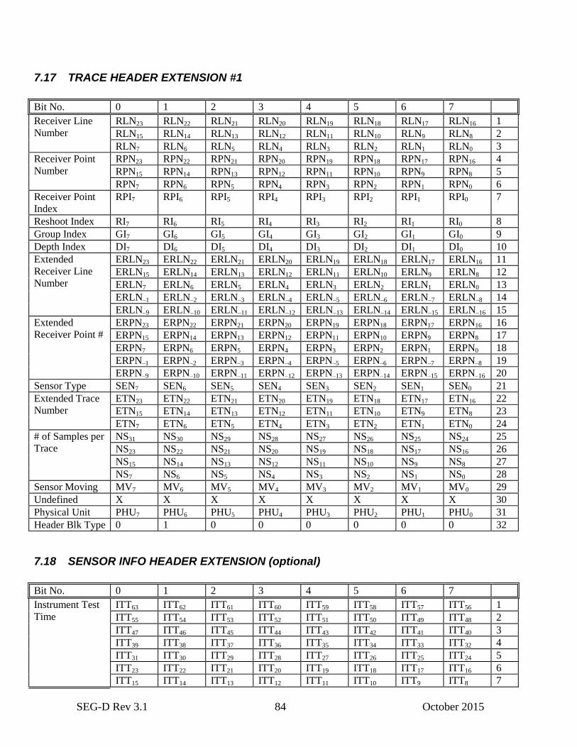
SEG-D Rev 3.1 84 October 2015
7.17 TRACE HEADER EXTENSION #1
Bit No. 0 1 2 3 4 5 6 7
Receiver Line
Number
RLN23 RLN22 RLN21 RLN20 RLN19 RLN18 RLN17 RLN16 1
RLN15 RLN14 RLN13 RLN12 RLN11 RLN10 RLN9 RLN8 2
RLN7 RLN6 RLN5 RLN4 RLN3 RLN2 RLN1 RLN0 3
Receiver Point
Number
RPN23 RPN22 RPN21 RPN20 RPN19 RPN18 RPN17 RPN16 4
RPN15 RPN14 RPN13 RPN12 RPN11 RPN10 RPN9 RPN8 5
RPN7 RPN6 RPN5 RPN4 RPN3 RPN2 RPN1 RPN0 6
Receiver Point
Index
RPI7 RPI6 RPI5 RPI4 RPI3 RPI2 RPI1 RPI0 7
Reshoot Index RI7 RI6 RI5 RI4 RI3 RI2 RI1 RI0 8
Group Index GI7 GI6 GI5 GI4 GI3 GI2 GI1 GI0 9
Depth Index DI7 DI6 DI5 DI4 DI3 DI2 DI1 DI0 10
Extended
Receiver Line
Number
ERLN23 ERLN22 ERLN21 ERLN20 ERLN19 ERLN18 ERLN17 ERLN16 11
ERLN15 ERLN14 ERLN13 ERLN12 ERLN11 ERLN10 ERLN9 ERLN8 12
ERLN7 ERLN6 ERLN5 ERLN4 ERLN3 ERLN2 ERLN1 ERLN0 13
ERLN–1 ERLN–2 ERLN–3 ERLN–4 ERLN–5 ERLN–6 ERLN–7 ERLN–8 14
ERLN–9 ERLN–10 ERLN–11 ERLN–12 ERLN–13 ERLN–14 ERLN–15 ERLN–16 15
Extended
Receiver Point #
ERPN23 ERPN22 ERPN21 ERPN20 ERPN19 ERPN18 ERPN17 ERPN16 16
ERPN15 ERPN14 ERPN13 ERPN12 ERPN11 ERPN10 ERPN9 ERPN8 17
ERPN7 ERPN6 ERPN5 ERPN4 ERPN3 ERPN2 ERPN1 ERPN0 18
ERPN–1 ERPN–2 ERPN–3 ERPN–4 ERPN–5 ERPN–6 ERPN–7 ERPN–8 19
ERPN–9 ERPN–10 ERPN–11 ERPN–12 ERPN–13 ERPN–14 ERPN–15 ERPN–16 20
Sensor Type SEN7 SEN6 SEN5 SEN4 SEN3 SEN2 SEN1 SEN0 21
Extended Trace
Number
ETN23 ETN22 ETN21 ETN20 ETN19 ETN18 ETN17 ETN16 22
ETN15 ETN14 ETN13 ETN12 ETN11 ETN10 ETN9 ETN8 23
ETN7 ETN6 ETN5 ETN4 ETN3 ETN2 ETN1 ETN0 24
# of Samples per
Trace
NS31 NS30 NS29 NS28 NS27 NS26 NS25 NS24 25
NS23 NS22 NS21 NS20 NS19 NS18 NS17 NS16 26
NS15 NS14 NS13 NS12 NS11 NS10 NS9 NS8 27
NS7 NS6 NS5 NS4 NS3 NS2 NS1 NS0 28
Sensor Moving MV7 MV6 MV5 MV4 MV3 MV2 MV1 MV0 29
Undefined X X X X X X X X 30
Physical Unit PHU7 PHU6 PHU5 PHU4 PHU3 PHU2 PHU1 PHU0 31
Header Blk Type 0 1 0 0 0 0 0 0 32
7.18 SENSOR INFO HEADER EXTENSION (optional)
Bit No. 0 1 2 3 4 5 6 7
Instrument Test
Time
ITT63 ITT62 ITT61 ITT60 ITT59 ITT58 ITT57 ITT56 1
ITT55 ITT54 ITT53 ITT52 ITT51 ITT50 ITT49 ITT48 2
ITT47 ITT46 ITT45 ITT44 ITT43 ITT42 ITT41 ITT40 3
ITT39 ITT38 ITT37 ITT36 ITT35 ITT34 ITT33 ITT32 4
ITT31 ITT30 ITT29 ITT28 ITT27 ITT26 ITT25 ITT24 5
ITT23 ITT22 ITT21 ITT20 ITT19 ITT18 ITT17 ITT16 6
ITT15 ITT14 ITT13 ITT12 ITT11 ITT10 ITT9 ITT8 7
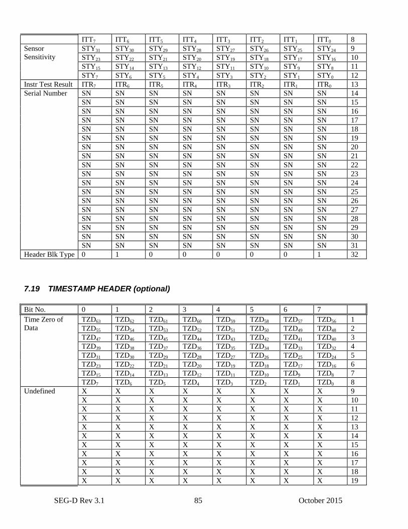
SEG-D Rev 3.1 85 October 2015
ITT7 ITT6 ITT5 ITT4 ITT3 ITT2 ITT1 ITT0 8
Sensor
Sensitivity
STY31 STY30 STY29 STY28 STY27 STY26 STY25 STY24 9
STY23 STY22 STY21 STY20 STY19 STY18 STY17 STY16 10
STY15 STY14 STY13 STY12 STY11 STY10 STY9 STY8 11
STY7 STY6 STY5 STY4 STY3 STY2 STY1 STY0 12
Instr Test Result ITR7 ITR6 ITR5 ITR4 ITR3 ITR2 ITR1 ITR0 13
Serial Number SN SN SN SN SN SN SN SN 14
SN SN SN SN SN SN SN SN 15
SN SN SN SN SN SN SN SN 16
SN SN SN SN SN SN SN SN 17
SN SN SN SN SN SN SN SN 18
SN SN SN SN SN SN SN SN 19
SN SN SN SN SN SN SN SN 20
SN SN SN SN SN SN SN SN 21
SN SN SN SN SN SN SN SN 22
SN SN SN SN SN SN SN SN 23
SN SN SN SN SN SN SN SN 24
SN SN SN SN SN SN SN SN 25
SN SN SN SN SN SN SN SN 26
SN SN SN SN SN SN SN SN 27
SN SN SN SN SN SN SN SN 28
SN SN SN SN SN SN SN SN 29
SN SN SN SN SN SN SN SN 30
SN SN SN SN SN SN SN SN 31
Header Blk Type 0 1 0 0 0 0 0 1 32
7.19 TIMESTAMP HEADER (optional)
Bit No. 0 1 2 3 4 5 6 7
Time Zero of
Data
TZD63 TZD62 TZD61 TZD60 TZD59 TZD58 TZD57 TZD56 1
TZD55 TZD54 TZD53 TZD52 TZD51 TZD50 TZD49 TZD48 2
TZD47 TZD46 TZD45 TZD44 TZD43 TZD42 TZD41 TZD40 3
TZD39 TZD38 TZD37 TZD36 TZD35 TZD34 TZD33 TZD32 4
TZD31 TZD30 TZD29 TZD28 TZD27 TZD26 TZD25 TZD24 5
TZD23 TZD22 TZD21 TZD20 TZD19 TZD18 TZD17 TZD16 6
TZD15 TZD14 TZD13 TZD12 TZD11 TZD10 TZD9 TZD8 7
TZD7 TZD6 TZD5 TZD4 TZD3 TZD2 TZD1 TZD0 8
Undefined X X X X X X X X 9
X X X X X X X X 10
X X X X X X X X 11
X X X X X X X X 12
X X X X X X X X 13
X X X X X X X X 14
X X X X X X X X 15
X X X X X X X X 16
X X X X X X X X 17
X X X X X X X X 18
X X X X X X X X 19

SEG-D Rev 3.1 86 October 2015
X X X X X X X X 20
X X X X X X X X 21
X X X X X X X X 22
X X X X X X X X 23
X X X X X X X X 24
X X X X X X X X 25
X X X X X X X X 26
X X X X X X X X 27
X X X X X X X X 28
X X X X X X X X 29
X X X X X X X X 30
X X X X X X X X 31
Header Blk Type 0 1 0 0 0 0 1 0 32
7.20 SENSOR CALIBRATION HEADER (optional)
Bit No. 0 1 2 3 4 5 6 7
Frequency 1 FR131 FR130 FR129 FR128 FR127 FR126 FR125 FR124 1
FR123 FR122 FR121 FR120 FR119 FR118 FR117 FR116 2
FR115 FR114 FR113 FR112 FR111 FR110 FR19 FR18 3
FR17 FR16 FR15 FR14 FR13 FR12 FR11 FR10 4
Amplitude 1 AM131 AM130 AM129 AM128 AM127 AM126 AM125 AM124 5
AM123 AM122 AM121 AM120 AM119 AM118 AM117 AM116 6
AM115 AM114 AM113 AM112 AM111 AM110 AM19 AM18 7
AM17 AM16 AM15 AM14 AM13 AM12 AM11 AM10 8
Phase 1 PH131 PH130 PH129 PH128 PH127 PH126 PH125 PH124 9
PH123 PH122 PH121 PH120 PH119 PH118 PH117 PH116 10
PH115 PH114 PH113 PH112 PH111 PH110 PH19 PH18 11
PH17 PH16 PH15 PH14 PH13 PH12 PH11 PH10 12
Frequency 2
FR231 FR230 FR229 FR228 FR227 FR226 FR225 FR224 13
FR223 FR222 FR221 FR220 FR219 FR218 FR217 FR216 14
FR215 FR214 FR213 FR212 FR211 FR210 FR29 FR28 15
FR27 FR26 FR25 FR24 FR23 FR22 FR21 FR20 16
Amplitude 2 AM231 AM230 AM229 AM228 AM227 AM226 AM225 AM224 17
AM223 AM222 AM221 AM220 AM219 AM218 AM217 AM216 18
AM215 AM214 AM213 AM212 AM211 AM210 AM29 AM28 19
AM27 AM26 AM25 AM24 AM23 AM22 AM21 AM20 20
Phase 2 PH231 PH230 PH229 PH228 PH227 PH226 PH225 PH224 21
PH223 PH222 PH221 PH220 PH219 PH218 PH217 PH216 22
PH215 PH214 PH213 PH212 PH211 PH210 PH29 PH28 23
PH27 PH26 PH25 PH24 PH23 PH22 PH21 PH20 24
Calibration applied CA7 CA6 CA5 CA4 CA3 CA2 CA1 CA0 25
Undefined X X X X X X X X 26
X X X X X X X X 27
X X X X X X X X 28
X X X X X X X X 29
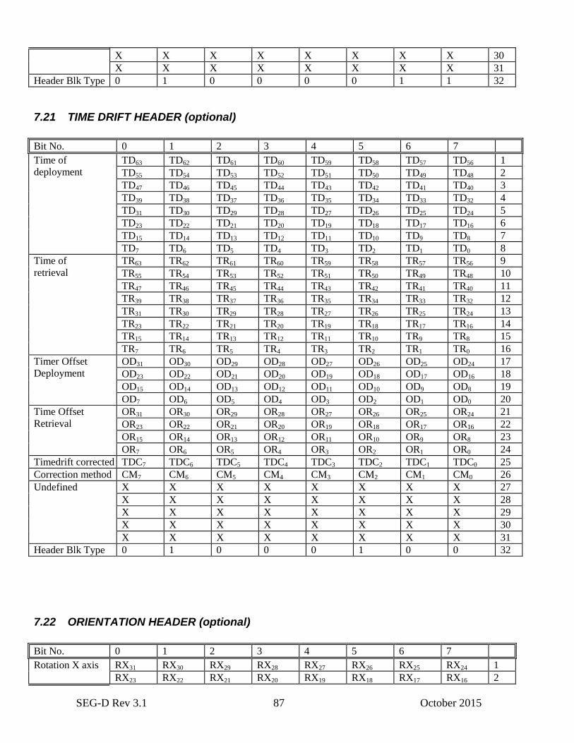
SEG-D Rev 3.1 87 October 2015
X X X X X X X X 30
X X X X X X X X 31
Header Blk Type 0 1 0 0 0 0 1 1 32
7.21 TIME DRIFT HEADER (optional)
Bit No. 0 1 2 3 4 5 6 7
Time of
deployment
TD63 TD62 TD61 TD60 TD59 TD58 TD57 TD56 1
TD55 TD54 TD53 TD52 TD51 TD50 TD49 TD48 2
TD47 TD46 TD45 TD44 TD43 TD42 TD41 TD40 3
TD39 TD38 TD37 TD36 TD35 TD34 TD33 TD32 4
TD31 TD30 TD29 TD28 TD27 TD26 TD25 TD24 5
TD23 TD22 TD21 TD20 TD19 TD18 TD17 TD16 6
TD15 TD14 TD13 TD12 TD11 TD10 TD9 TD8 7
TD7 TD6 TD5 TD4 TD3 TD2 TD1 TD0 8
Time of
retrieval
TR63 TR62 TR61 TR60 TR59 TR58 TR57 TR56 9
TR55 TR54 TR53 TR52 TR51 TR50 TR49 TR48 10
TR47 TR46 TR45 TR44 TR43 TR42 TR41 TR40 11
TR39 TR38 TR37 TR36 TR35 TR34 TR33 TR32 12
TR31 TR30 TR29 TR28 TR27 TR26 TR25 TR24 13
TR23 TR22 TR21 TR20 TR19 TR18 TR17 TR16 14
TR15 TR14 TR13 TR12 TR11 TR10 TR9 TR8 15
TR7 TR6 TR5 TR4 TR3 TR2 TR1 TR0 16
Timer Offset
Deployment
OD31 OD30 OD29 OD28 OD27 OD26 OD25 OD24 17
OD23 OD22 OD21 OD20 OD19 OD18 OD17 OD16 18
OD15 OD14 OD13 OD12 OD11 OD10 OD9 OD8 19
OD7 OD6 OD5 OD4 OD3 OD2 OD1 OD0 20
Time Offset
Retrieval
OR31 OR30 OR29 OR28 OR27 OR26 OR25 OR24 21
OR23 OR22 OR21 OR20 OR19 OR18 OR17 OR16 22
OR15 OR14 OR13 OR12 OR11 OR10 OR9 OR8 23
OR7 OR6 OR5 OR4 OR3 OR2 OR1 OR0 24
Timedrift corrected TDC7 TDC6 TDC5 TDC4 TDC3 TDC2 TDC1 TDC0 25
Correction method CM7 CM6 CM5 CM4 CM3 CM2 CM1 CM0 26
Undefined X X X X X X X X 27
X X X X X X X X 28
X X X X X X X X 29
X X X X X X X X 30
X X X X X X X X 31
Header Blk Type 0 1 0 0 0 1 0 0 32
7.22 ORIENTATION HEADER (optional)
Bit No. 0 1 2 3 4 5 6 7
Rotation X axis RX31 RX30 RX29 RX28 RX27 RX26 RX25 RX24 1
RX23 RX22 RX21 RX20 RX19 RX18 RX17 RX16 2
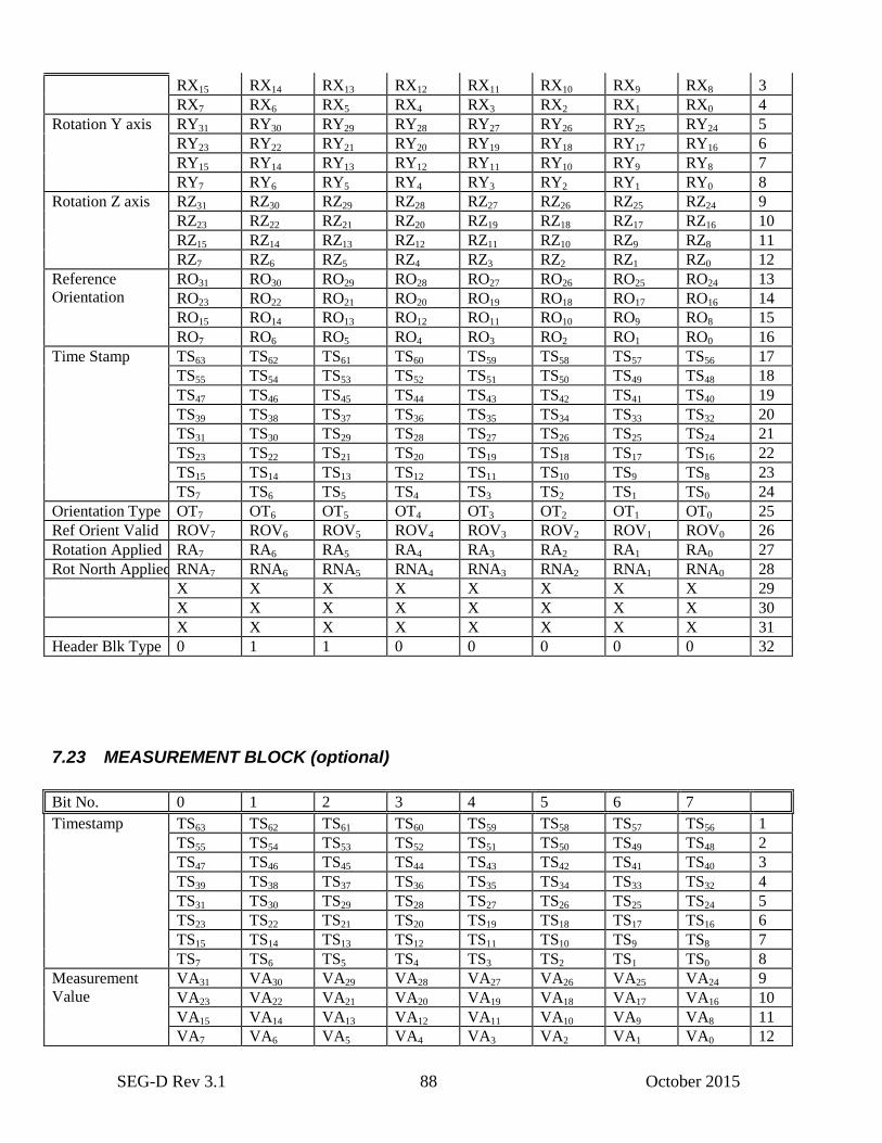
SEG-D Rev 3.1 88 October 2015
RX15 RX14 RX13 RX12 RX11 RX10 RX9 RX8 3
RX7 RX6 RX5 RX4 RX3 RX2 RX1 RX0 4
Rotation Y axis RY31 RY30 RY29 RY28 RY27 RY26 RY25 RY24 5
RY23 RY22 RY21 RY20 RY19 RY18 RY17 RY16 6
RY15 RY14 RY13 RY12 RY11 RY10 RY9 RY8 7
RY7 RY6 RY5 RY4 RY3 RY2 RY1 RY0 8
Rotation Z axis RZ31 RZ30 RZ29 RZ28 RZ27 RZ26 RZ25 RZ24 9
RZ23 RZ22 RZ21 RZ20 RZ19 RZ18 RZ17 RZ16 10
RZ15 RZ14 RZ13 RZ12 RZ11 RZ10 RZ9 RZ8 11
RZ7 RZ6 RZ5 RZ4 RZ3 RZ2 RZ1 RZ0 12
Reference
Orientation
RO31 RO30 RO29 RO28 RO27 RO26 RO25 RO24 13
RO23 RO22 RO21 RO20 RO19 RO18 RO17 RO16 14
RO15 RO14 RO13 RO12 RO11 RO10 RO9 RO8 15
RO7 RO6 RO5 RO4 RO3 RO2 RO1 RO0 16
Time Stamp TS63 TS62 TS61 TS60 TS59 TS58 TS57 TS56 17
TS55 TS54 TS53 TS52 TS51 TS50 TS49 TS48 18
TS47 TS46 TS45 TS44 TS43 TS42 TS41 TS40 19
TS39 TS38 TS37 TS36 TS35 TS34 TS33 TS32 20
TS31 TS30 TS29 TS28 TS27 TS26 TS25 TS24 21
TS23 TS22 TS21 TS20 TS19 TS18 TS17 TS16 22
TS15 TS14 TS13 TS12 TS11 TS10 TS9 TS8 23
TS7 TS6 TS5 TS4 TS3 TS2 TS1 TS0 24
Orientation Type OT7 OT6 OT5 OT4 OT3 OT2 OT1 OT0 25
Ref Orient Valid ROV7 ROV6 ROV5 ROV4 ROV3 ROV2 ROV1 ROV0 26
Rotation Applied RA7 RA6 RA5 RA4 RA3 RA2 RA1 RA0 27
Rot North Applied RNA7 RNA6 RNA5 RNA4 RNA3 RNA2 RNA1 RNA0 28
X X X X X X X X 29
X X X X X X X X 30
X X X X X X X X 31
Header Blk Type 0 1 1 0 0 0 0 0 32
7.23 MEASUREMENT BLOCK (optional)
Bit No. 0 1 2 3 4 5 6 7
Timestamp TS63 TS62 TS61 TS60 TS59 TS58 TS57 TS56 1
TS55 TS54 TS53 TS52 TS51 TS50 TS49 TS48 2
TS47 TS46 TS45 TS44 TS43 TS42 TS41 TS40 3
TS39 TS38 TS37 TS36 TS35 TS34 TS33 TS32 4
TS31 TS30 TS29 TS28 TS27 TS26 TS25 TS24 5
TS23 TS22 TS21 TS20 TS19 TS18 TS17 TS16 6
TS15 TS14 TS13 TS12 TS11 TS10 TS9 TS8 7
TS7 TS6 TS5 TS4 TS3 TS2 TS1 TS0 8
Measurement
Value
VA31 VA30 VA29 VA28 VA27 VA26 VA25 VA24 9
VA23 VA22 VA21 VA20 VA19 VA18 VA17 VA16 10
VA15 VA14 VA13 VA12 VA11 VA10 VA9 VA8 11
VA7 VA6 VA5 VA4 VA3 VA2 VA1 VA0 12
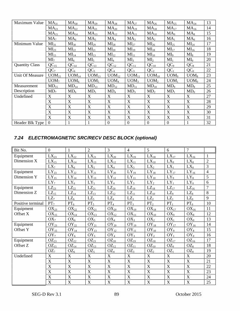
SEG-D Rev 3.1 89 October 2015
Maximum Value MA31 MA30 MA29 MA28 MA27 MA26 MA25 MA24 13
MA23 MA22 MA21 MA20 MA19 MA18 MA17 MA16 14
MA15 MA14 MA13 MA12 MA11 MA10 MA9 MA8 15
MA7 MA6 MA5 MA4 MA3 MA2 MA1 MA0 16
Minimum Value
MI31 MI30 MI29 MI28 MI27 MI26 MI25 MI24 17
MI23 MI22 MI21 MI20 MI19 MI18 MI17 MI16 18
MI15 MI14 MI13 MI12 MI11 MI10 MI9 MI8 19
MI7 MI6 MI5 MI4 MI3 MI2 MI1 MI0 20
Quantity Class QC15 QC14 QC13 QC12 QC11 QC10 QC9 QC8 21
QC7 QC6 QC5 QC4 QC3 QC2 QC1 QC0 22
Unit Of Measure
UOM15 UOM14 UOM13 UOM12 UOM11 UOM10 UOM9 UOM8 23
UOM7 UOM6 UOM5 UOM4 UOM3 UOM2 UOM1 UOM0 24
Measurement
Description
MD15 MD14 MD13 MD12 MD11 MD10 MD9 MD8 25
MD7 MD6 MD5 MD4 MD3 MD2 MD1 MD0 26
Undefined X X X X X X X X 27
X X X X X X X X 28
X X X X X X X X 29
X X X X X X X X 30
X X X X X X X X 31
Header Blk Type 0 1 1 0 0 0 0 1 32
7.24 ELECTROMAGNETIC SRC/RECV DESC BLOCK (optional)
Bit No. 0 1 2 3 4 5 6 7
Equipment
Dimension X
LX23 LX22 LX21 LX20 LX19 LX18 LX17 LX16 1
LX15 LX14 LX13 LX12 LX11 LX10 LX9 LX8 2
LX7 LX6 LX5 LX4 LX3 LX2 LX1 LX0 3
Equipment LY23 LY22 LY21 LY20 LY19 LY18 LY17 LY16 4
Dimension Y LY15 LY14 LY13 LY12 LY11 LY10 LY9 LY8 5
LY7 LY6 LY5 LY4 LY3 LY2 LY1 LY0 6
Equipment
Dimension Z
LZ23 LZ22 LZ21 LZ20 LZ19 LZ18 LZ17 LZ16 7
LZ15 LZ14 LZ13 LZ12 LZ11 LZ10 LZ9 LZ8 8
LZ7 LZ6 LZ5 LZ4 LZ3 LZ2 LZ1 LZ0 9
Positive terminal PT7 PT6 PT5 PT4 PT3 PT2 PT1 PT0 10
Equipment OX23 OX22 OX21 OX20 OX19 OX18 OX17 OX16 11
Offset X OX15 OX14 OX13 OX12 OX11 OX10 OX9 OX8 12
OX7 OX6 OX5 OX4 OX3 OX2 OX1 OX0 13
Equipment OY23 OY22 OY21 OY20 OY19 OY18 OY17 OY16 14
Offset Y OY15 OY14 OY13 OY12 OY11 OY10 OY9 OY8 15
OY7 OY6 OY5 OY4 OY3 OY2 OY1 OY0 16
Equipment OZ23 OZ22 OZ21 OZ20 OZ19 OZ18 OZ17 OZ16 17
Offset Z OZ15 OZ14 OZ13 OZ12 OZ11 OZ10 OZ9 OZ8 18
OZ7 OZ6 OZ5 OZ4 OZ3 OZ2 OZ1 OZ0 19
Undefined X X X X X X X X 20
X X X X X X X X 21
X X X X X X X X 22
X X X X X X X X 23
X X X X X X X X 24
X X X X X X X X 25
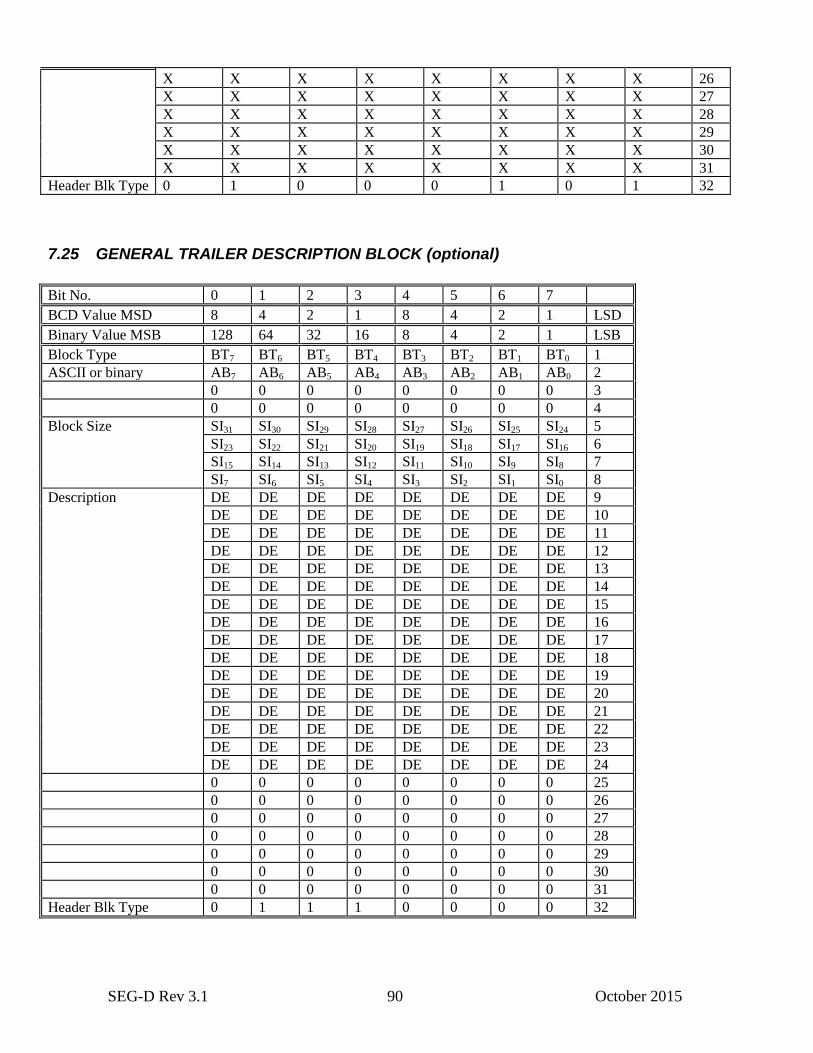
SEG-D Rev 3.1 90 October 2015
X X X X X X X X 26
X X X X X X X X 27
X X X X X X X X 28
X X X X X X X X 29
X X X X X X X X 30
X X X X X X X X 31
Header Blk Type 0 1 0 0 0 1 0 1 32
7.25 GENERAL TRAILER DESCRIPTION BLOCK (optional)
Bit No. 0 1 2 3 4 5 6 7
BCD Value MSD 8 4 2 1 8 4 2 1 LSD
Binary Value MSB 128 64 32 16 8 4 2 1 LSB
Block Type BT7 BT6 BT5 BT4 BT3 BT2 BT1 BT0 1
ASCII or binary AB7 AB6 AB5 AB4 AB3 AB2 AB1 AB0 2
0 0 0 0 0 0 0 0 3
0 0 0 0 0 0 0 0 4
Block Size SI31 SI30 SI29 SI28 SI27 SI26 SI25 SI24 5
SI23 SI22 SI21 SI20 SI19 SI18 SI17 SI16 6
SI15 SI14 SI13 SI12 SI11 SI10 SI9 SI8 7
SI7 SI6 SI5 SI4 SI3 SI2 SI1 SI0 8
Description DE DE DE DE DE DE DE DE 9
DE DE DE DE DE DE DE DE 10
DE DE DE DE DE DE DE DE 11
DE DE DE DE DE DE DE DE 12
DE DE DE DE DE DE DE DE 13
DE DE DE DE DE DE DE DE 14
DE DE DE DE DE DE DE DE 15
DE DE DE DE DE DE DE DE 16
DE DE DE DE DE DE DE DE 17
DE DE DE DE DE DE DE DE 18
DE DE DE DE DE DE DE DE 19
DE DE DE DE DE DE DE DE 20
DE DE DE DE DE DE DE DE 21
DE DE DE DE DE DE DE DE 22
DE DE DE DE DE DE DE DE 23
DE DE DE DE DE DE DE DE 24
0 0 0 0 0 0 0 0 25
0 0 0 0 0 0 0 0 26
0 0 0 0 0 0 0 0 27
0 0 0 0 0 0 0 0 28
0 0 0 0 0 0 0 0 29
0 0 0 0 0 0 0 0 30
0 0 0 0 0 0 0 0 31
Header Blk Type 0 1 1 1 0 0 0 0 32
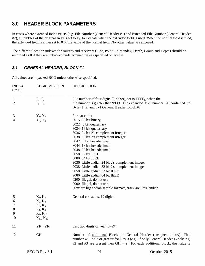
SEG-D Rev 3.1 91 October 2015
8.0 HEADER BLOCK PARAMETERS
In cases where extended fields exists (e.g. File Number (General Header #1) and Extended File Number (General Header
#2), all nibbles of the original field is set to F16 to indicate when the extended field is used. When the normal field is used,
the extended field is either set to 0 or the value of the normal field. No other values are allowed.
The different location indexes for sources and receivers (Line, Point, Point index, Depth, Group and Depth) should be
recorded as 0 if they are unknown/undetermined unless specified otherwise.
8.1 GENERAL HEADER, BLOCK #1
All values are in packed BCD unless otherwise specified.
INDEX ABBREVIATION DESCRIPTION
BYTE
_____ _________________________________________________________________
1 F1, F2 File number of four digits (0–9999), set to FFFF16 when the
2 F3, F4 file number is greater than 9999. The expanded file number is contained in
Bytes 1, 2, and 3 of General Header, Block #2.
3 Y1, Y2 Format code:
4 Y3, Y4 8015 20 bit binary
8022 8 bit quaternary
8024 16 bit quaternary
8036 24 bit 2's complement integer
8038 32 bit 2's complement integer
8042 8 bit hexadecimal
8044 16 bit hexadecimal
8048 32 bit hexadecimal
8058 32 bit IEEE
8080 64 bit IEEE
9036 Little endian 24 bit 2's complement integer
9038 Little endian 32 bit 2's complement integer
9058 Little endian 32 bit IEEE
9080 Little endian 64 bit IEEE
0200 Illegal, do not use
0000 Illegal, do not use
80xx are big endian sample formats, 90xx are little endian.
5 K1, K2 General constants, 12 digits
6 K3, K4
7 K5, K6
8 K7, K8
9 K9, K10
10 K11, K12
11 YR1, YR2 Last two digits of year (0–99)
12 GH Number of additional Blocks in General Header (unsigned binary). This
number will be 2 or greater for Rev 3 (e.g., if only General Header Blocks #1,
#2 and #3 are present then GH = 2). For each additional block, the value is
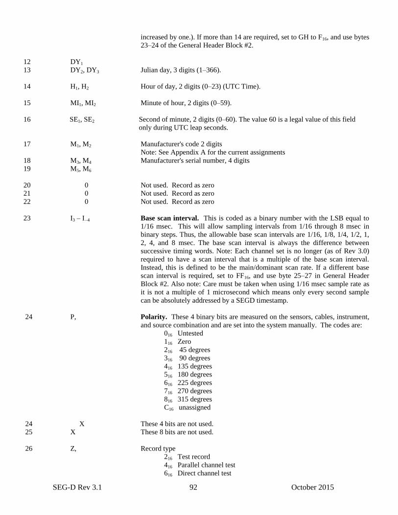
SEG-D Rev 3.1 92 October 2015
increased by one.). If more than 14 are required, set to GH to F16, and use bytes
23–24 of the General Header Block #2.
12 DY1
13 DY2, DY3 Julian day, 3 digits (1–366).
14 H1, H2 Hour of day, 2 digits (0–23) (UTC Time).
15 MI1, MI2 Minute of hour, 2 digits (0–59).
16 SE1, SE2 Second of minute, 2 digits (0–60). The value 60 is a legal value of this field
only during UTC leap seconds.
17 M1, M2 Manufacturer's code 2 digits
Note: See Appendix A for the current assignments
18 M3, M4 Manufacturer's serial number, 4 digits
19 M5, M6
20 0 Not used. Record as zero
21 0 Not used. Record as zero
22 0 Not used. Record as zero
23 I3 – I –4 Base scan interval. This is coded as a binary number with the LSB equal to
1/16 msec. This will allow sampling intervals from 1/16 through 8 msec in
binary steps. Thus, the allowable base scan intervals are 1/16, 1/8, 1/4, 1/2, 1,
2, 4, and 8 msec. The base scan interval is always the difference between
successive timing words. Note: Each channel set is no longer (as of Rev 3.0)
required to have a scan interval that is a multiple of the base scan interval.
Instead, this is defined to be the main/dominant scan rate. If a different base
scan interval is required, set to FF16, and use byte 25–27 in General Header
Block #2. Also note: Care must be taken when using 1/16 msec sample rate as
it is not a multiple of 1 microsecond which means only every second sample
can be absolutely addressed by a SEGD timestamp.
24 P, Polarity. These 4 binary bits are measured on the sensors, cables, instrument,
and source combination and are set into the system manually. The codes are:
016 Untested
116 Zero
216 45 degrees
316 90 degrees
416 135 degrees
516 180 degrees
616 225 degrees
716 270 degrees
816 315 degrees
C16 unassigned
24 X These 4 bits are not used.
25 X These 8 bits are not used.
26 Z, Record type
216 Test record
416 Parallel channel test
616 Direct channel test
SEG-D Rev 3.1 93 October 2015
816 Normal record
116 Other
26 R1,
27 R2, R3 Record length from time zero (in increments of 0.5 times 1.024 sec). This
value can be set from 00.5 to 99.5 representing times from 0.512 sec. to
101.888 sec. A setting of 00.0 indicates the record length is indeterminate.
These three nibbles must be set to FFF16 when using the Extended Record
Length (record length in milliseconds), bytes 17-20, in General Header Block
#2. This is the maximum record length for any trace in the record. If Extended
Recording Mode is used (General Header #3 byte 29 set to 1), Record Length
must be set to 00.0.
28 ST/R1, ST/R2 Scan types per record. This 2 digit code is the number of scan types per record
(0–99).
29 CS1, CS2 Number of channel sets per scan type (0–99). (Set to FF16 when using
Extended Channel Sets/Scan Type.) This 2 digit code is the number of channel
sets per scan. If multiple scan types are used (such as in a switching sampling
interval environment), this number is equal to the number of channel sets
contained in the scan type with the largest number of channel sets. If scan
types also exist with less than this maximum number of channel sets per scan
type, dummy channel set descriptors will have to be recorded in the Scan Type
Header. This can be done by setting the number of channels in the dummy
channel set descriptor to zero (reference Bytes 21 - 23 of the Scan Type Header
description).
30 SK1, SK2 Number of 32 byte fields added to the end of each scan type header in order to
record the sample skew of all channels (0–99). (See Appendix E.2 of the SEG-
D Standard). Zero indicates that skew is not recorded. If more skew records
are required, set to FF16, and use bytes 9 and 10 of General Header Block #2.
31 EC1, EC2 Extended Header length. The Extended Header is used to record additional
equipment parameters. The two digits (0–99) in this field specify the number
of 32 byte extensions. If more than 99 extensions, then these bytes are set to
FF16. Bytes 6, 7 and 8 of General Header Block #2 contain the number of 32
byte extensions.
32 EX1, EX2 External Header length. The External Header is used to record additional user
supplied information in the header. The two digits (0–99) in this field specify
the number of 32 byte extensions. If more than 99 extensions, then these bytes
are set to FF16. Bytes 28, 29 and 30 of General Header Block #2 contain the
number of 32 byte extensions.
8.2 GENERAL HEADER BLOCK #2
INDEX ABBREVIATION DESCRIPTION
BYTE
_____ _______________ __________________________________________
SEG-D Rev 3.1 94 October 2015
1,2,3 EF23 – EF0 Extended File Number (three bytes, unsigned binary). For file numbers greater
than the 9999, bytes 1 and 2 of the General Header Block #1 must be set to
FFFF16.
4,5 EN15 – EN0 Extended Channel Sets/Scan Type (two bytes, unsigned binary). Allows the
number of Channel Sets/Scan Type to be greater than the 99 supported in the
standard General Header Block #1 (byte 29). When using the Extended
Channel Sets/Scan Type, byte 29 of General Header Block #1 must be set to
FF16.
6,7,8 ECX23 – ECX0 Extended Header Blocks (three bytes, unsigned binary). Allows the number of
Extended Header Blocks (of 32 bytes each) to be greater than the 99 allowed
by the standard General Header Block #1 (byte 31). To use more than 99
Extended Header Blocks, set byte 31 of General Header Block #1 to FF16, and
use these two bytes. Max size 536,870,880 bytes or 512 MB.
9,10 ESK15 – ESK0 Extended Skew Blocks (two bytes, unsigned binary). Number of 32 byte fields
added to the end of each scan type header in order to record the sample skew of
all channels. (See Appendix E2 of the SEG-D Standard). Zero indicates that
skew is not recorded. When using the Extended Skew blocks field, byte 30 of
General Header Block #1 must be set to FF16.
11 RMJ7 – RMJ0 Major SEG-D Revision Number (one byte, unsigned binary). Set to 0316.
12 RMN7 – RMN0 Minor SEG-D Revision Number (one byte, unsigned binary). Set to 0116.
Revisions 0 to 0.N are not valid. This version is Rev 3.1.
13–16 GT31 – GT0 Number of Blocks of General Trailer (four bytes, unsigned binary). The
number of 32 byte blocks to be used for General Trailers. Max size
137,438,953,408 bytes or 128 GB. If not known at the time (i.e. to allow easy
appending of trailer blocks while data is stored on disk), it may be set to
FFFFFFFF16. The reader will then have to read the trailer block by block to
determine the shot size. It is strongly recommended to set this field to its
correct value when recording to tape.
17–20 ERL31 – ERL0 Extended Record Length (four bytes, unsigned binary) indicates the record
length in microseconds. When using extended record length, the record length
in the General Header Block #1, the Record Length in bytes 26 and 27 must be
set to FFF16. A value of 0.0 means record length is indeterminate. Note: This is
the maximum record length for any trace in the record. Please refer to the
channel set descriptor for actual information of start and end times, number of
samples per trace etc. Also note that negative start times are allowed. If
Extended Recording Mode is used (General Header #3 byte 29 set to 1),
Extended Record Length must be set to 0.0.
21,22 SN15 – SN0 Record set number. (two bytes, unsigned binary) This is the sequence number
(e.g. the line’s unique sequence number), swath number, or any other
applicable number that may be used to identify this group of shot records. Set
to 0 if not valid. Allows values of 1–65535.
23,24 EGH15 – EGH0 Extended Number of additional Blocks in the General Header (two bytes,
unsigned binary). This number will be 2 or greater for Rev 3 (e.g. If only
General Header Blocks #1, #2 and #3 are present then EGH = 2). For each
additional block, the value is increased by one.) When using this field, the
upper nibble of byte 12 of General Header Block #1 must be set to F16.
SEG-D Rev 3.1 95 October 2015
25,26,27 BSI23 – BSI0 Dominant Sampling Interval (3 bytes, unsigned binary). Only used if General
Header Block #1 (byte 23) is set to FF16. Dominant sampling interval in
microseconds (1/1000000 second). As sample rates allowed in SEG-D Rev 3.0
and above are very flexible, this is no longer related to the base scan interval
(term used in Rev 2.x and below) with each channel set being a multiple of it.
Instead, it is the main or dominant sampling interval for the record. The
sampling interval within each channel set (byte 24-26 of the channel set
header) should be used to find the correct sampling interval. This field should
not be used to calculate size of records or traces in the record. The field is left
for backwards compatibility. It can assume a value from 0 to 16,777,215. A
value of 0 means the dominant sampling interval is indeterminate.
28,29,30 EH23 – EH0 External Header Blocks (3 bytes, unsigned binary). Allows the number of 32
byte External Header Blocks to be greater than the 99 allowed by General
Header Block #1, byte 32. To use more than 99 External Header Blocks, set
byte 32 of General Header Block #1 to FF16, and use these three bytes.
Maximum size is 536,870,880 bytes or 512 MB.
31 X These 8 bits are undefined by the format and may have any value. Note: In
future versions these may be defined, so use with caution.
32 HT7 – HT0 Header block type (one byte, unsigned binary). The header type indicates what
type of information is contained in this header. For General Header Block #2
this byte is set to 0216.
NOTES:
1. Where the range of allowable numbers is not indicated, the follow ranges apply:
One byte, unsigned binary, range is 0 – 255
Two bytes, unsigned binary, range is 0 – 65535
Three bytes, unsigned binary, range is 0 – 16777215
Four bytes, unsigned binary, range is 0 – 4294967295
8.3 GENERAL HEADER BLOCK #3 (Timestamp and size header)
INDEX ABBREVIATION DESCRIPTION
BYTE
_____ _______________ __________________________________________
1–8 TZ63 – TZ0 Time Zero for this record (eight bytes, SEG-D timestamp). The time data and
events in this record are offset from (by using e.g. Channel Set Start Time).
Matches timestamp in General Header Block #1 bytes 11–16, but is accurate to
1 microsecond. If the recorder does not know the absolute time, this must be
recorded as 0, and all timestamps in the record will be relative to this time. If
absolute timing of all data traces and events is used in the record (i.e. by
utilizing Timestamp Header, Additional Source Info Header etc.), the TZ
value may be freely chosen by the recorder. It is however highly recommended
to use a time close to the start of the data/events in the record.
9–16 RS63 – RS0 Record Size (eight bytes, unsigned binary). The total size of the SEG-D record
in number of bytes. May be set to 0 if unknown (e.g., the size of the General
Trailer is set to FFFFFFFF16 in bytes 13–16 in General Header Block #2). It is
strongly recommended to set this field to a proper value unless absolutely
SEG-D Rev 3.1 96 October 2015
necessary. If no General Trailer blocks exist, this field is equal to the Data Size
(bytes 17–24). The field is very useful for any byte oriented devices like disks
or networks.
17–24 DS63 – DS0 Data Size (eight bytes, unsigned binary). The total size of the headers and data
in this record in number of bytes. This value enables skipping of all traces to
the beginning of the trailer. If no General Trailer exists, this is equal to the
Record Size (bytes 9–16). The field is very useful for any byte oriented devices
like disks and networks.
25–28 HS31 – HS0 Header Size (four bytes, unsigned binary). The total size of the headers (i.e.
General Headers, Channel Set Headers, Skew Headers, External Header,
Extended Header, etc.) in this record in number of bytes. This value enables
skipping of all headers to the beginning of the first trace. The field is very
useful for any byte oriented devices like disks or networks.
29 ERM7 – ERM0 Extended Recording Mode (one byte, unsigned binary). Set to 1 if this record is
using the Extended Recording Mode, 0 for normal record.
30 RTM7 – RTM0 Relative Time Mode (one byte, unsigned binary). Set to 1 if this record does
not contain absolute timestamps, 0 for normal record. If set to 1, bytes 1 to 8
(TZ) must be set to 0, and all timestamps in the record must be relative to this
time (i.e. start of record).
31 X These 8 bits are undefined by the format and may have any value. Note: In
future versions these may be defined, so use with caution.
32 HT7 – HT0 Header block type (one byte, unsigned binary). The header type indicates what
type of information is contained in this header. For General Header Block #3
this byte is set to 0316.
8.4 GENERAL HEADER BLOCK #4 (Vessel/Crew Identification) (optional)
This block contains the name/description of the vessel or crew.
INDEX ABBREVIATION DESCRIPTION
BYTE
_____ _____________ __________________________________________
1,2,3 VCA Abbreviated vessel or crew name (3 characters, ASCII). May be used on tape
labels, etc. Left justified, padded with space (2016) characters. May be blank if
no abbreviation exists.
4–31 VC Vessel or crew name (ASCII text). 28 character vessel or crew name which
uniquely identifies the vessel/crew within the enterprise. Left justified, padded
with space (2016) characters.
32 HT7 – HT0 Header block type (1 byte, unsigned binary). Set to 1016 for Vessel/Crew
Identification.

SEG-D Rev 3.1 97 October 2015
8.5 GENERAL HEADER BLOCK #5 (Survey Area Name) (optional)
This block contains the name/description of the survey area.
INDEX ABBREVIATION DESCRIPTION
BYTE
_____ _____________ __________________________________________
1–31 SAN Survey Area Name (ASCII text). 31 character survey area name which
properly identifies the area the record was recorded in. Left justified, padded
with space (2016) characters.
32 HT7 – HT0 Header block type (1 byte, unsigned binary). Set to 1116 for Survey Area Name.
8.6 GENERAL HEADER BLOCK #6 (Client Identification) (optional)
This block contains the name/description of the client.
INDEX ABBREVIATION DESCRIPTION
BYTE
_____ _____________ __________________________________________
1–31 CI Client Identification (ASCII text). 31 character client name/identification
which properly identifies the client for this survey. Left justified, padded with
space (2016) characters.
32 HT7 – HT0 Header block type (1 byte, unsigned binary). Set to 1216 for Client Identifica-
tion.
8.7 GENERAL HEADER BLOCK #7 (Job identification) (optional)
This block contains the name/description of the job/survey.
INDEX ABBREVIATION DESCRIPTION
BYTE
_____ _____________ __________________________________________
1–5 JIA Abbreviated Job Identification (5 characters ASCII). May be used on tape
labels etc. Left justified, padded with space (2016) characters. May be blank if
no abbreviation exists.
6–31 JI Job Identification (ASCII text). 26 character job name/number/identification
which properly identifies the survey within the enterprise. Left justified,
padded with space (2016) characters.
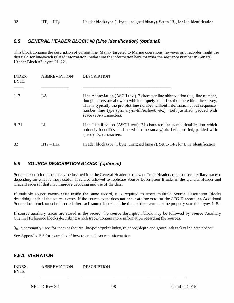
SEG-D Rev 3.1 98 October 2015
32 HT7 – HT0 Header block type (1 byte, unsigned binary). Set to 1316 for Job Identification.
8.8 GENERAL HEADER BLOCK #8 (Line identification) (optional)
This block contains the description of current line. Mainly targeted to Marine operations, however any recorder might use
this field for line/swath related information. Make sure the information here matches the sequence number in General
Header Block #2, bytes 21–22.
INDEX ABBREVIATION DESCRIPTION
BYTE
_____ _____________ __________________________________________
1–7 LA Line Abbreviation (ASCII text). 7 character line abbreviation (e.g. line number,
though letters are allowed) which uniquely identifies the line within the survey.
This is typically the pre-plot line number without information about sequence-
number, line type (primary/in-fill/reshoot, etc.) Left justified, padded with
space (2016) characters.
8–31 LI Line Identification (ASCII text). 24 character line name/identification which
uniquely identifies the line within the survey/job. Left justified, padded with
space (2016) characters.
32 HT7 – HT0 Header block type (1 byte, unsigned binary). Set to 1416 for Line Identification.
8.9 SOURCE DESCRIPTION BLOCK (optional)
Source description blocks may be inserted into the General Header or relevant Trace Headers (e.g. source auxiliary traces),
depending on what is most useful. It is also allowed to replicate Source Description Blocks in the General Header and
Trace Headers if that may improve decoding and use of the data.
If multiple source events exist inside the same record, it is required to insert multiple Source Description Blocks
describing each of the source events. If the source event does not occur at time zero for the SEG-D record, an Additional
Source Info block must be inserted after each source block and the time of the event must be properly stored in bytes 1–8.
If source auxiliary traces are stored in the record, the source description block may be followed by Source Auxiliary
Channel Reference blocks describing which traces contain more information regarding the sources.
016 is commonly used for indexes (source line/point/point index, re-shoot, depth and group indexes) to indicate not set.
See Appendix E.7 for examples of how to encode source information.
8.9.1 VIBRATOR
INDEX ABBREVIATION DESCRIPTION
BYTE
_____ _____________ _________________________________________________
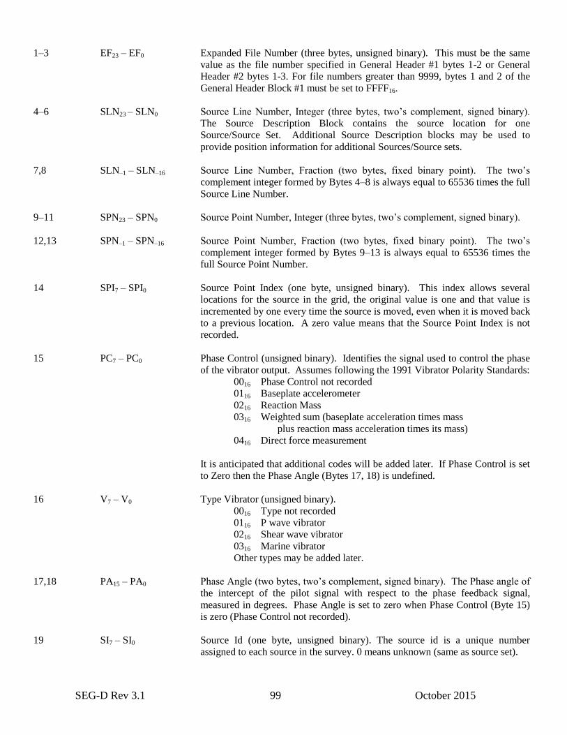
SEG-D Rev 3.1 99 October 2015
1–3 EF23 – EF0 Expanded File Number (three bytes, unsigned binary). This must be the same
value as the file number specified in General Header #1 bytes 1-2 or General
Header #2 bytes 1-3. For file numbers greater than 9999, bytes 1 and 2 of the
General Header Block #1 must be set to FFFF16.
4–6 SLN23 – SLN0 Source Line Number, Integer (three bytes, two’s complement, signed binary).
The Source Description Block contains the source location for one
Source/Source Set. Additional Source Description blocks may be used to
provide position information for additional Sources/Source sets.
7,8 SLN–1 – SLN–16 Source Line Number, Fraction (two bytes, fixed binary point). The two’s
complement integer formed by Bytes 4–8 is always equal to 65536 times the full
Source Line Number.
9–11 SPN23 – SPN0 Source Point Number, Integer (three bytes, two’s complement, signed binary).
12,13 SPN–1 – SPN–16 Source Point Number, Fraction (two bytes, fixed binary point). The two’s
complement integer formed by Bytes 9–13 is always equal to 65536 times the
full Source Point Number.
14 SPI7 – SPI0 Source Point Index (one byte, unsigned binary). This index allows several
locations for the source in the grid, the original value is one and that value is
incremented by one every time the source is moved, even when it is moved back
to a previous location. A zero value means that the Source Point Index is not
recorded.
15 PC7 – PC0 Phase Control (unsigned binary). Identifies the signal used to control the phase
of the vibrator output. Assumes following the 1991 Vibrator Polarity Standards:
0016 Phase Control not recorded
0116 Baseplate accelerometer
0216 Reaction Mass
0316 Weighted sum (baseplate acceleration times mass
plus reaction mass acceleration times its mass)
0416 Direct force measurement
It is anticipated that additional codes will be added later. If Phase Control is set
to Zero then the Phase Angle (Bytes 17, 18) is undefined.
16 V7 – V0 Type Vibrator (unsigned binary).
0016 Type not recorded
0116 P wave vibrator
0216 Shear wave vibrator
0316 Marine vibrator
Other types may be added later.
17,18 PA15 – PA0 Phase Angle (two bytes, two’s complement, signed binary). The Phase angle of
the intercept of the pilot signal with respect to the phase feedback signal,
measured in degrees. Phase Angle is set to zero when Phase Control (Byte 15)
is zero (Phase Control not recorded).
19 SI7 – SI0 Source Id (one byte, unsigned binary). The source id is a unique number
assigned to each source in the survey. 0 means unknown (same as source set).
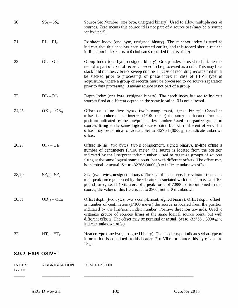
SEG-D Rev 3.1 100 October 2015
20 SS7 – SS0 Source Set Number (one byte, unsigned binary). Used to allow multiple sets of
sources. Zero means this source id is not part of a source set (may be a source
set by itself).
21 RI7 – RI0 Re-shoot Index (one byte, unsigned binary). The re-shoot index is used to
indicate that this shot has been recorded earlier, and this record should replace
it. Re-shoot index starts at 0 (indicates recorded for first time).
22 GI7 – GI0 Group Index (one byte, unsigned binary). Group index is used to indicate this
record is part of a set of records needed to be processed as a unit. This may be a
stack fold number/vibrator sweep number in case of recording records that must
be stacked prior to processing, or phase index in case of HFVS type of
acquisition, where a group of records must be processed to do source separation
prior to data processing. 0 means source is not part of a group
23 DI7 – DI0 Depth Index (one byte, unsigned binary). The depth index is used to indicate
sources fired at different depths on the same location. 0 is not allowed.
24,25 OX15 – OX0 Offset cross-line (two bytes, two’s complement, signed binary). Cross-line
offset is number of centimeters (1/100 meter) the source is located from the
position indicated by the line/point index number. Used to organize groups of
sources firing at the same logical source point, but with different offsets. The
offset may be nominal or actual. Set to -32768 (800016) to indicate unknown
offset.
26,27 OI15 – OI0 Offset in-line (two bytes, two’s complement, signed binary). In-line offset is
number of centimeters (1/100 meter) the source is located from the position
indicated by the line/point index number. Used to organize groups of sources
firing at the same logical source point, but with different offsets. The offset may
be nominal or actual. Set to -32768 (800016) to indicate unknown offset.
28,29 SZ15 – SZ0 Size (two bytes, unsigned binary). The size of the source. For vibrator this is the
total peak force generated by the vibrators associated with this source. Unit 100
pound force, i.e. if 4 vibrators of a peak force of 70000lbs is combined in this
source, the value of this field is set to 2800. Set to 0 if unknown.
30,31 OD15 – OD0 Offset depth (two bytes, two’s complement, signed binary). Offset depth offset
is number of centimeters (1/100 meter) the source is located from the position
indicated by the line/point index number. Positive direction upwards. Used to
organize groups of sources firing at the same logical source point, but with
different offsets. The offset may be nominal or actual. Set to -32768 ( 800016) to
indicate unknown offset.
32 HT7 – HT0 Header type (one byte, unsigned binary). The header type indicates what type of
information is contained in this header. For Vibrator source this byte is set to
1516.
8.9.2 EXPLOSIVE
INDEX ABBREVIATION DESCRIPTION
BYTE
_____ _____________ ___________________________________________________
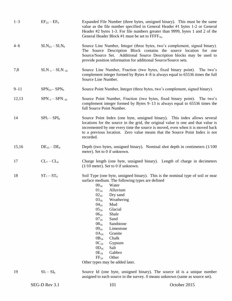
SEG-D Rev 3.1 101 October 2015
1–3 EF23 – EF0 Expanded File Number (three bytes, unsigned binary). This must be the same
value as the file number specified in General Header #1 bytes 1-2 or General
Header #2 bytes 1-3. For file numbers greater than 9999, bytes 1 and 2 of the
General Header Block #1 must be set to FFFF16.
4–6 SLN23 – SLN0 Source Line Number, Integer (three bytes, two’s complement, signed binary).
The Source Description Block contains the source location for one
Source/Source Set. Additional Source Description blocks may be used to
provide position information for additional Source/Source sets.
7,8 SLN–1 – SLN–16 Source Line Number, Fraction (two bytes, fixed binary point). The two’s
complement integer formed by Bytes 4–8 is always equal to 65536 times the full
Source Line Number.
9–11 SPN23 – SPN0 Source Point Number, Integer (three bytes, two’s complement, signed binary).
12,13 SPN–1 – SPN–16 Source Point Number, Fraction (two bytes, fixed binary point). The two’s
complement integer formed by Bytes 9–13 is always equal to 65536 times the
full Source Point Number.
14 SPI7 – SPI0 Source Point Index (one byte, unsigned binary). This index allows several
locations for the source in the grid, the original value is one and that value is
incremented by one every time the source is moved, even when it is moved back
to a previous location. Zero value means that the Source Point Index is not
recorded.
15,16 DE15 – DE0 Depth (two bytes, unsigned binary). Nominal shot depth in centimeters (1/100
meter). Set to 0 if unknown.
17 CL7 – CL0 Charge length (one byte, unsigned binary). Length of charge in decimeters
(1/10 meter). Set to 0 if unknown.
18 ST7 – ST0 Soil Type (one byte, unsigned binary). This is the nominal type of soil or near
surface medium. The following types are defined
0016 Water
0116 Alluvium
0216 Dry sand
0316 Weathering
0416 Mud
0516 Glacial
0616 Shale
0716 Sand
0816 Sandstone
0916 Limestone
0A16 Granite
0B16 Chalk
0C16 Gypsum
0D16 Salt
0E16 Gabbro
FF16 Other
Other types may be added later.
19 SI7 – SI0 Source Id (one byte, unsigned binary). The source id is a unique number
assigned to each source in the survey. 0 means unknown (same as source set).

SEG-D Rev 3.1 102 October 2015
20 SS7 – SS0 Source Set Number (one byte, unsigned binary). Used to allow multiple sets of
sources. Zero means this source id is not part of a source set (may be a source
set by itself).
21 RI7 – RI0 Re-shoot Index (one byte, unsigned binary). The re-shoot index is used to
indicate that this shot has been recorded earlier, and this record should replace
it. Re-shoot index starts at 0 (indicates recorded for first time).
22 GI7 – GI0 Group Index (one byte, unsigned binary). Group index is used to indicate this
record is part of a set of records needed to be processed as a unit. 0 means
source not part of a group..
23 DI7 – DI0 Depth Index (one byte, unsigned binary). The depth index is used to indicate
sources fired at different depths on the same location. 0 is not allowed.
24,25 OX15 – OX0 Offset cross-line (two bytes, two’s complement, signed binary). Cross-line
offset is number of centimeters (1/100 meter) the source is located from the
position indicated by the line/point index number. Used to organize groups of
sources firing at the same logical source point, but with different offsets. The
offset may be nominal or actual. Set to -32768 (800016) to indicate unknown
offset.
26,27 OI15 – OI0 Offset in-line (two bytes, two’s complement, signed binary). In-line offset is
number of centimeters (1/100 meter) the source is located from the position
indicated by the line/point index number. Used to organize groups of sources
firing at the same logical source point, but with different offsets. The offset may
be nominal or actual. Set to -32768 (800016) to indicate unknown offset.
28,29 SZ15 – SZ0 Size (two bytes, two’s complement, signed binary). The size of source. For
explosive this is the size of charge in grams. Set to 0 if unknown.
30,31 OD15 – OD0 Offset depth (two bytes, two’s complement, signed binary). Offset depth offset
is number of centimeters (1/100 meter) the source is located from the position
indicated by the line/point index number. Positive direction upwards. Used to
organize groups of sources firing at the same logical source point, but with
different offsets. The offset may be nominal or actual. Set to -32768 ( 800016) to
indicate unknown offset.
32 HT7 – HT0 Header type (one byte, unsigned binary). The header type indicates what type of
information is contained in this header. For Explosive source this byte is set to
1616.
8.9.3 AIRGUNs
INDEX ABBREVIATION DESCRIPTION
BYTE
_____ _____________ ___________________________________________________
1–3 EF23 – EF0 Expanded File Number (three bytes, unsigned binary). This must be the same
value as the file number specified in General Header #1 bytes 1-2 or General

SEG-D Rev 3.1 103 October 2015
Header #2 bytes 1-3. For file numbers greater than 9999, bytes 1 and 2 of the
General Header Block #1 must be set to FFFF16.
4–6 SLN23 – SLN0 Source Line Number, Integer (three bytes, two’s complement, signed binary).
The Source Description Block contains the source location for one
Source/Source Set. Additional Source Description blocks may be used to
provide position information for additional Source/Source sets.
7,8 SLN–1 – SLN–16 Source Line Number, Fraction (two bytes, fixed binary point). The two’s
complement integer formed by Bytes 4–8 is always equal to 65536 times the full
Source Line Number.
9–11 SPN23 – SPN0 Source Point Number, Integer (three bytes, two’s complement, signed binary).
12,13 SPN–1 – SPN–16 Source Point Number, Fraction (two bytes, fixed binary point). The two’s
complement integer formed by Bytes 9–13 is always equal to 65536 times the
full Source Point Number.
14 SPI7 – SPI0 Source Point Index (one byte, unsigned binary). This index allows several
locations for the source in the grid, the original value is one and that value is
incremented by one every time the source is moved, even when it is moved back
to a previous location. Zero value means that the Source Point Index is not
recorded.
15,16 DE15 – DE0 Depth (two bytes, unsigned binary). This is the nominal depth from the water
surface in centimeters (1/100 meter) for this source. Allows values of 0–655.35
meters. Set to 0 if unknown.
17,18 AP15 – AP0 Air Pressure (two bytes, unsigned binary). The nominal operating air pressure
Unit is PSI. Set to 0 if unknown.
19 SI7 – SI0 Source Id (one byte, unsigned binary). The source id is a unique number
assigned to each source in the survey. 0 means unknown (same as source set).
20 SS7 – SS0 Source Set Number (one byte, unsigned binary). Used to allow multiple sets of
sources. Zero means this source id is not part of a source set (may be a source
set by itself).
21 RI7 – RI0 Re-shoot Index (one byte, unsigned binary). The re-shoot index is used to
indicate that this shot has been recorded earlier, and this record should replace
it. Re-shoot index starts at 0 (indicates recorded for first time).
22 GI7 – GI0 Group Index (one byte, unsigned binary). Group index is used to indicate this
record is part of a set of records needed to be processed as a unit.0 means source
not part of a group.
23 DI7 – DI0 Depth Index (one byte, unsigned binary). The depth index is used to indicate
sources fired at different depths on the same location. 0 is not allowed.
24,25 OX15 – OX0 Offset cross-line (two bytes, two’s complement, signed binary). Cross-line
offset is number of centimeters (1/100 meter) the source is located from the
position indicated by the line/point index number. Used to organize groups of
sources firing at the same logical source point, but with different offsets. The

SEG-D Rev 3.1 104 October 2015
offset may be nominal or actual. Set to -32768 (800016) to indicate unknown
offset.
26,27 OI15 – OI0 Offset in-line (two bytes, two’s complement, signed binary). In-line offset is
number of centimeters (1/100 meter) the source is located from the position
indicated by the line/point index number. Used to organize groups of sources
firing at the same logical source point, but with different offsets. The offset may
be nominal or actual. Set to -32768 (800016) to indicate unknown offset.
28,29 SZ15 – SZ0 Size (two bytes, two’s complement, signed binary). The size of source. For
Airgun this is the combined volume of the guns associated with this source ID.
Unit cubic inches. Set to 0 if unknown.
30,31 OD15 – OD0 Offset depth (two bytes, two’s complement, signed binary). Offset depth offset
is number of centimeters (1/100 meter) the source is located from the position
indicated by the line/point index number. Positive direction upwards. Used to
organize groups of sources firing at the same logical source point, but with
different offsets. The offset may be nominal or actual. Set to -32768 ( 800016) to
indicate unknown offset.
32 HT7 – HT0 Header type (one byte, unsigned binary). The header type indicates what type of
information is contained in this header. For Airgun source this byte is set to
1716.
8.9.4 WATERGUN
INDEX ABBREVIATION DESCRIPTION
BYTE
_____ _____________ ___________________________________________________
1–3 EF23 – EF0 Expanded File Number (three bytes, unsigned binary). This must be the same
value as the file number specified in General Header #1 bytes 1-2 or General
Header #2 bytes 1-3. For file numbers greater than 9999, bytes 1 and 2 of the
General Header Block #1 must be set to FFFF16.
4–6 SLN23 – SLN0 Source Line Number, Integer (three bytes, two’s complement, signed binary).
The Source Description Block contains the source location for one
Source/Source Set. Additional Source Description blocks may be used to
provide position information for additional Source/Source sets.
7,8 SLN–1 – SLN–16 Source Line Number, Fraction (two bytes, fixed binary point). The two’s
complement integer formed by Bytes 4–8 is always equal to 65536 times the full
Source Line Number.
9–11 SPN23 – SPN0 Source Point Number, Integer (three bytes, two’s complement, signed binary).
12,13 SPN–1 – SPN–16 Source Point Number, Fraction (two bytes, fixed binary point). The two’s
complement integer formed by Bytes 9–13 is always equal to 65536 times the
full Source Point Number.
14 SPI7 – SPI0 Source Point Index (one byte, unsigned binary). This index allows several
locations for the source in the grid, the original value is one and that value is
incremented by one every time the source is moved, even when it is moved back
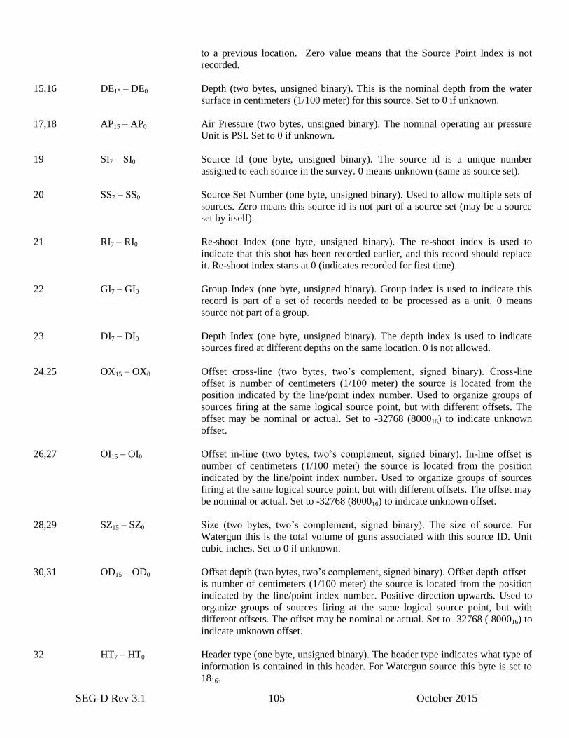
SEG-D Rev 3.1 105 October 2015
to a previous location. Zero value means that the Source Point Index is not
recorded.
15,16 DE15 – DE0 Depth (two bytes, unsigned binary). This is the nominal depth from the water
surface in centimeters (1/100 meter) for this source. Set to 0 if unknown.
17,18 AP15 – AP0 Air Pressure (two bytes, unsigned binary). The nominal operating air pressure
Unit is PSI. Set to 0 if unknown.
19 SI7 – SI0 Source Id (one byte, unsigned binary). The source id is a unique number
assigned to each source in the survey. 0 means unknown (same as source set).
20 SS7 – SS0 Source Set Number (one byte, unsigned binary). Used to allow multiple sets of
sources. Zero means this source id is not part of a source set (may be a source
set by itself).
21 RI7 – RI0 Re-shoot Index (one byte, unsigned binary). The re-shoot index is used to
indicate that this shot has been recorded earlier, and this record should replace
it. Re-shoot index starts at 0 (indicates recorded for first time).
22 GI7 – GI0 Group Index (one byte, unsigned binary). Group index is used to indicate this
record is part of a set of records needed to be processed as a unit. 0 means
source not part of a group.
23 DI7 – DI0 Depth Index (one byte, unsigned binary). The depth index is used to indicate
sources fired at different depths on the same location. 0 is not allowed.
24,25 OX15 – OX0 Offset cross-line (two bytes, two’s complement, signed binary). Cross-line
offset is number of centimeters (1/100 meter) the source is located from the
position indicated by the line/point index number. Used to organize groups of
sources firing at the same logical source point, but with different offsets. The
offset may be nominal or actual. Set to -32768 (800016) to indicate unknown
offset.
26,27 OI15 – OI0 Offset in-line (two bytes, two’s complement, signed binary). In-line offset is
number of centimeters (1/100 meter) the source is located from the position
indicated by the line/point index number. Used to organize groups of sources
firing at the same logical source point, but with different offsets. The offset may
be nominal or actual. Set to -32768 (800016) to indicate unknown offset.
28,29 SZ15 – SZ0 Size (two bytes, two’s complement, signed binary). The size of source. For
Watergun this is the total volume of guns associated with this source ID. Unit
cubic inches. Set to 0 if unknown.
30,31 OD15 – OD0 Offset depth (two bytes, two’s complement, signed binary). Offset depth offset
is number of centimeters (1/100 meter) the source is located from the position
indicated by the line/point index number. Positive direction upwards. Used to
organize groups of sources firing at the same logical source point, but with
different offsets. The offset may be nominal or actual. Set to -32768 ( 800016) to
indicate unknown offset.
32 HT7 – HT0 Header type (one byte, unsigned binary). The header type indicates what type of
information is contained in this header. For Watergun source this byte is set to
1816.
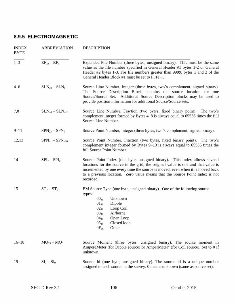
SEG-D Rev 3.1 106 October 2015
8.9.5 ELECTROMAGNETIC
INDEX ABBREVIATION DESCRIPTION
BYTE
_____ _____________ ___________________________________________________
1–3 EF23 – EF0 Expanded File Number (three bytes, unsigned binary). This must be the same
value as the file number specified in General Header #1 bytes 1-2 or General
Header #2 bytes 1-3. For file numbers greater than 9999, bytes 1 and 2 of the
General Header Block #1 must be set to FFFF16.
4–6 SLN23 – SLN0 Source Line Number, Integer (three bytes, two’s complement, signed binary).
The Source Description Block contains the source location for one
Source/Source Set. Additional Source Description blocks may be used to
provide position information for additional Source/Source sets.
7,8 SLN–1 – SLN–16 Source Line Number, Fraction (two bytes, fixed binary point). The two’s
complement integer formed by Bytes 4–8 is always equal to 65536 times the full
Source Line Number.
9–11 SPN23 – SPN0 Source Point Number, Integer (three bytes, two’s complement, signed binary).
12,13 SPN–1 – SPN–16 Source Point Number, Fraction (two bytes, fixed binary point). The two’s
complement integer formed by Bytes 9–13 is always equal to 65536 times the
full Source Point Number.
14 SPI7 – SPI0 Source Point Index (one byte, unsigned binary). This index allows several
locations for the source in the grid, the original value is one and that value is
incremented by one every time the source is moved, even when it is moved back
to a previous location. Zero value means that the Source Point Index is not
recorded.
15 ST7 – ST0 EM Source Type (one byte, unsigned binary). One of the following source
types:
0016 Unknown
0116 Dipole
0216 Loop Coil
0316 Airborne
0416 Open Loop
0516 Closed loop
0F16 Other
16–18 MO23 – MO0 Source Moment (three bytes, unsigned binary). The source moment in
AmpereMeter (for Dipole source) or AmperMeter2 (for Coil source). Set to 0 if
unknown.
19 SI7 – SI0 Source Id (one byte, unsigned binary). The source id is a unique number
assigned to each source in the survey. 0 means unknown (same as source set).

SEG-D Rev 3.1 107 October 2015
20 SS7 – SS0 Source Set Number (one byte, unsigned binary). Used to allow multiple sets of
sources. Zero means this source id is not part of a source set (may be a source
set by itself).
21 RI7 – RI0 Re-shoot Index (one byte, unsigned binary). The re-shoot index is used to
indicate that this shot has been recorded earlier, and this record should replace
it. Re-shoot index starts at 0 (indicates recorded for first time).
22 GI7 – GI0 Group Index (one byte, unsigned binary). Group index is used to indicate this
record is part of a set of records needed to be processed as a unit. 0 means
source not part of a group.
23 DI7 – DI0 Depth Index (one byte, unsigned binary). The depth index is used to indicate
sources fired at different depths on the same location. 0 is not allowed.
24,25 OX15 – OX0 Offset cross-line (two bytes, two’s complement, signed binary). Cross-line
offset is number of centimeters (1/100 meter) the source is located from the
position indicated by the line/point index number. Used to organize groups of
sources firing at the same logical source point, but with different offsets. The
offset may be nominal or actual. Set to -32768 (800016) to indicate unknown
offset.
26,27 OI15 – OI0 Offset in-line (two bytes, two’s complement, signed binary). In-line offset is
number of centimeters (1/100 meter) the source is located from the position
indicated by the line/point index number. Used to organize groups of sources
firing at the same logical source point, but with different offsets. The offset may
be nominal or actual. Set to -32768 (800016) to indicate unknown offset.
28,29 CV15 – CV0 Source Current or Voltage (two bytes, unsigned binary). The source current (in
Ampere) or voltage (in Volts), depending on the source type. Set to 0 if
unknown.
30,31 OD15 – OD0 Offset depth (two bytes, two’s complement, signed binary). Offset depth offset
is number of centimeters (1/100 meter) the source is located from the position
indicated by the line/point index number. Positive direction upwards. Used to
organize groups of sources firing at the same logical source point, but with
different offsets. The offset may be nominal or actual. Set to -32768 ( 800016) to
indicate unknown offset.
32 HT7 – HT0 Header type (one byte, unsigned binary). The header type indicates what type of
information is contained in this header. For Electromagnetic source this byte is
set to 1916.
8.9.6 OTHER SOURCE
INDEX ABBREVIATION DESCRIPTION
BYTE
_____ _____________ ___________________________________________________
1–3 EF23 – EF0 Expanded File Number (three bytes, unsigned binary). This must be the same
value as the file number specified in General Header #1 bytes 1-2 or General
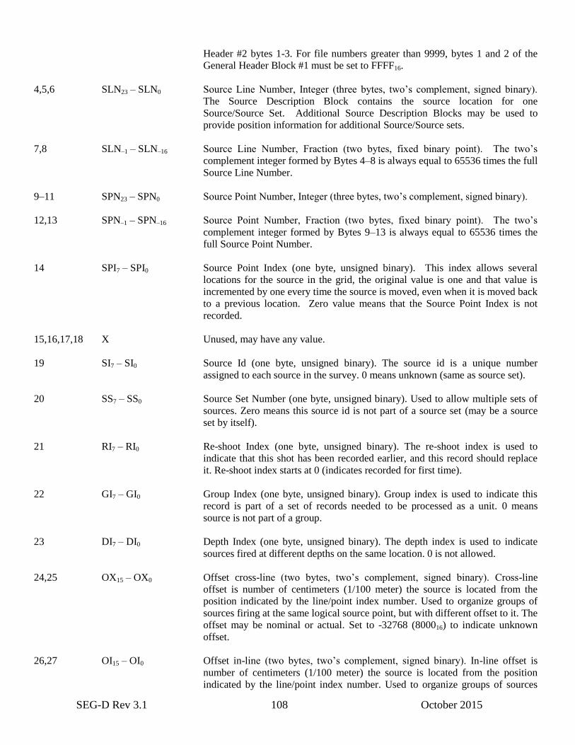
SEG-D Rev 3.1 108 October 2015
Header #2 bytes 1-3. For file numbers greater than 9999, bytes 1 and 2 of the
General Header Block #1 must be set to FFFF16.
4,5,6 SLN23 – SLN0 Source Line Number, Integer (three bytes, two’s complement, signed binary).
The Source Description Block contains the source location for one
Source/Source Set. Additional Source Description Blocks may be used to
provide position information for additional Source/Source sets.
7,8 SLN–1 – SLN–16 Source Line Number, Fraction (two bytes, fixed binary point). The two’s
complement integer formed by Bytes 4–8 is always equal to 65536 times the full
Source Line Number.
9–11 SPN23 – SPN0 Source Point Number, Integer (three bytes, two’s complement, signed binary).
12,13 SPN–1 – SPN–16 Source Point Number, Fraction (two bytes, fixed binary point). The two’s
complement integer formed by Bytes 9–13 is always equal to 65536 times the
full Source Point Number.
14 SPI7 – SPI0 Source Point Index (one byte, unsigned binary). This index allows several
locations for the source in the grid, the original value is one and that value is
incremented by one every time the source is moved, even when it is moved back
to a previous location. Zero value means that the Source Point Index is not
recorded.
15,16,17,18 X Unused, may have any value.
19 SI7 – SI0 Source Id (one byte, unsigned binary). The source id is a unique number
assigned to each source in the survey. 0 means unknown (same as source set).
20 SS7 – SS0 Source Set Number (one byte, unsigned binary). Used to allow multiple sets of
sources. Zero means this source id is not part of a source set (may be a source
set by itself).
21 RI7 – RI0 Re-shoot Index (one byte, unsigned binary). The re-shoot index is used to
indicate that this shot has been recorded earlier, and this record should replace
it. Re-shoot index starts at 0 (indicates recorded for first time).
22 GI7 – GI0 Group Index (one byte, unsigned binary). Group index is used to indicate this
record is part of a set of records needed to be processed as a unit. 0 means
source is not part of a group.
23 DI7 – DI0 Depth Index (one byte, unsigned binary). The depth index is used to indicate
sources fired at different depths on the same location. 0 is not allowed.
24,25 OX15 – OX0 Offset cross-line (two bytes, two’s complement, signed binary). Cross-line
offset is number of centimeters (1/100 meter) the source is located from the
position indicated by the line/point index number. Used to organize groups of
sources firing at the same logical source point, but with different offset to it. The
offset may be nominal or actual. Set to -32768 (800016) to indicate unknown
offset.
26,27 OI15 – OI0 Offset in-line (two bytes, two’s complement, signed binary). In-line offset is
number of centimeters (1/100 meter) the source is located from the position
indicated by the line/point index number. Used to organize groups of sources
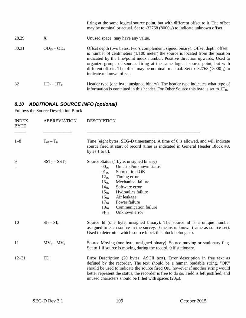
SEG-D Rev 3.1 109 October 2015
firing at the same logical source point, but with different offset to it. The offset
may be nominal or actual. Set to -32768 (800016) to indicate unknown offset.
28,29 X Unused space, may have any value.
30,31 OD15 – OD0 Offset depth (two bytes, two’s complement, signed binary). Offset depth offset
is number of centimeters (1/100 meter) the source is located from the position
indicated by the line/point index number. Positive direction upwards. Used to
organize groups of sources firing at the same logical source point, but with
different offsets. The offset may be nominal or actual. Set to -32768 ( 800016) to
indicate unknown offset.
32 HT7 – HT0 Header type (one byte, unsigned binary). The header type indicates what type of
information is contained in this header. For Other Source this byte is set to 1F16.
8.10 ADDITIONAL SOURCE INFO (optional)
Follows the Source Description Block
INDEX ABBREVIATION DESCRIPTION
BYTE
_____ _____________ ___________________________________________________
1–8 T63 – T0 Time (eight bytes, SEG-D timestamp). A time of 0 is allowed, and will indicate
source fired at start of record (time as indicated in General Header Block #3,
bytes 1 to 8).
9 SST7 – SST0 Source Status (1 byte, unsigned binary)
. 0016 Untested/unknown status
0116 Source fired OK
1216 Timing error
1316 Mechanical failure
1416 Software error
1516 Hydraulics failure
1616 Air leakage
1716 Power failure
1816 Communication failure
FF16 Unknown error
10 SI7 – SI0 Source Id (one byte, unsigned binary). The source id is a unique number
assigned to each source in the survey. 0 means unknown (same as source set).
Used to determine which source block this block belongs to.
11 MV7 – MV0 Source Moving (one byte, unsigned binary). Source moving or stationary flag.
Set to 1 if source is moving during the record, 0 if stationary.
12–31 ED Error Description (20 bytes, ASCII text). Error description in free text as
defined by the recorder. The text should be a human readable string. "OK"
should be used to indicate the source fired OK, however if another string would
better represent the status, the recorder is free to do so. Field is left justified, and
unused characters should be filled with spaces (2016).

SEG-D Rev 3.1 110 October 2015
32 HT7 – HT0 Header type (one byte, unsigned binary). The header type indicates what type of
information is contained in this header. For Additional Source Info this byte is
set to 2016.
8.11 SOURCE AUXILIARY CHANNEL REFERENCE (optional)
Follows the Source Description Block
This block is inserted into the General Header (or Trace Header) after the Source Description Block to indicate which
auxiliary channels contain information data regarding the source. Multiple Source Auxiliary Channel Reference blocks
may be used for each source if necessary. May be inserted into (auxiliary source) trace headers to indicate which (other)
traces are related to the source.
A value of 0 for Source Id, Scan Type Number, Channel Set Number and Trace Number means no channel referenced.
INDEX ABBREVIATION DESCRIPTION
BYTE
_____ _____________ ___________________________________________________
1 SI7 – SI0 Source Id (one byte, unsigned binary). The source id is a unique number
assigned to each source in the survey.
2 ST11, ST12 Channel 1, Scan Type Number (one byte, two digit, BCD). Currently only
values 1–99 allowed.
3,4 CS115 – CS10 Channel 1, Channel Set Number (two bytes, unsigned binary).
5–7 TN123 – TN10 Channel 1, Trace Number (3 bytes, unsigned binary).
8 ST21, ST22 Channel 2, Scan Type Number (one byte, two digit, BCD). Currently only
values 1–99 allowed.
9,10 CS215 – CS20 Channel 2, Channel Set Number (two bytes, unsigned binary).
11–13 TN223 – TN20 Channel 2, Trace Number (three bytes, unsigned binary).
14 ST31, ST32 Channel 3, Scan Type Number (one byte, two digit, BCD). Currently only
values 1–99 allowed.
15,16 CS315 – CS30 Channel 3, Channel Set Number (two bytes, unsigned binary).
17–19 TN323 – TN30 Channel 3, Trace Number (three byte, unsigned binary).
20 ST41, ST42 Channel 4, Scan Type Number (one byte, two digit, BCD). Currently only
values 1–99 allowed.
21, 22 CS415 – CS40 Channel 4, Channel Set Number (two bytes, unsigned binary).
23–25 TN423 – TN40 Channel 4, Trace Number. (three byte, unsigned binary).
26 ST51, ST52 Channel 5, Scan Type Number (one byte, two digit, BCD). Currently only
values 1–99 allowed.
27, 28 CS515 – CS50 Channel 5, Channel Set Number (two bytes, unsigned binary).
SEG-D Rev 3.1 111 October 2015
29–31 TN523 – TN50 Channel 5, Trace Number (three bytes, unsigned binary).
32 HT7 – HT0 Header type (one byte, unsigned binary). The header type indicates what type of
information is contained in this header. For Source Auxiliary Channel Reference
this byte is set to 2116.
8.12 COORDINATE REFERENCE SYSTEM IDENTIFICATION (conditional)
This header block is mandatory if a position block is included in the record.
INDEX ABBREVIATION DESCRIPTION
BYTE
_____ _______________ __________________________________________
1–31 CRID CRS ID (31 bytes, ASCII text). The coordinate reference system (CRS)
identification in a textual format as defined in Appendix D1 or D2. The format
described in D2 (old SEG-D 3.0 stanza format) is deprecated, but still
supported.
The string contains all CRS definition strings (including Location Data and
Location Data Transformations) used in the record, concatenated into a
continuous string. For OGP P1/11 format each header record should be
terminated by a carriage return (Hex 0x0D) and/or a line feed (Hex 0x0A)
character. For stanza format (appendix D2), it is recommended that each stanza
is separated by a newline terminator ('\n', 0A16) or Carriage Return/LineFeed
("\r\n", 0D0A16).
The string is split into 31 byte blocks, and stored in multiple, consecutive CRS
identification blocks as part of the General Header. Text is left justified, the
block is padded with space (2016) characters if needed.
32 HT7 – HT0 Header type (one byte, unsigned binary). The header type indicates what type of
information is contained in this header. For Coordinate Reference System
Identification this byte is set to 5516.
8.13 POSITION BLOCKS (optional)
The location of the Position blocks in the header will determine what the position refers to, i.e. the Position blocks will
describe the position of the blocks they follow. For example: Position blocks following a Source Description block will
describe the position of the source, Position blocks following a Demux Trace Header will describe the position of the
trace, and Position blocks following a Measurement block will describe the position of the measurement.
Note: There may be other blocks between the Position blocks and the block they describe the position of (see e.g. the
Source block description in Section 5.1).
INDEX ABBREVIATION DESCRIPTION
BYTE
_____ ________________________________________________________________

SEG-D Rev 3.1 112 October 2015
1–8 TP63 – TP0 Time of position (eight bytes, SEG-D timestamp). Time to which this position
applies, i.e., sample time.
9–16 TC63 – TC0 Time of measurement/calculation (eight bytes, SEG-D timestamp). Time the
position was measured or calculated.
17–20 VE31 – VE0 Vertical error quality estimate: 95% precision estimate in same units as vertical
coordinate (four bytes, IEEE float). Set to 0 if coordinate reference type only
uses the horizontal plane. Set to infinity (exponent all bits set, mantissa all
zeroes) if not available.
21–24 HEA31 – HEA0 Horizontal error quality estimate: 95% error ellipse semi-major axis in same
units as horizontal coordinate (four bytes, IEEE float). Set to 0 if coordinate
reference type only uses the vertical plane. Set to infinity (exponent all bits set,
mantissa all zeroes) if not available. HEA, HEB and HEO must all be valid, or
all be infinity.
25–28 HEB31 – HEB0 Horizontal error quality estimate: 95% error ellipse semi-minor axis in same
units as horizontal coordinate (four bytes, IEEE float). Set to 0 if coordinate
reference type only uses the vertical plane. Set to infinity (exponent all bits set,
mantissa all zeroes) if not available. HEA, HEB and HEO must all be valid, or
all be infinity.
29–30 HEO15 – HEO0 Horizontal error quality estimate: Bearing of error ellipse semi-major axis (two
bytes, unsigned binary). Orientation to CRS north axis (defined by HC,1,6,1
record of OGP P1/11 standard) in steps of 1/100 of a degree. Set to 0 if
coordinate reference type only uses the vertical plane. Set FFFF16 if not
available. HEA, HEB and HEO must all be valid, or all be infinity.
31 PT7 – PT0 Position type (one byte, unsigned binary). The type of position. The following
types are supported:
0116 Planned/preplot
0216 Measured
0316 Processed
0416 Final
0F16 Unknown
32 HT7 – HT0 Header block type (one byte, unsigned binary). Set to 5016 for Position Block 1.
INDEX ABBREVIATION DESCRIPTION
BYTE
_____ ________________________________________________________________
33–40 T1C163 – T1C10 First coordinate for coordinate tuple 1/CRS A (eight bytes, IEEE double float).
This coordinate and its unit is as given by its CRSREF in the CRS definition
(or by the location data stanza) identified through ID1. Set to infinity (exponent
all bits set, mantissa all zeroes) if CRS type is one-dimensional i.e. vertical.
SEG-D Rev 3.1 113 October 2015
41–48 T1C263 – T1C20 Second coordinate for coordinate tuple 1/CRS A (eight bytes, IEEE double
float). This coordinate and its unit is as given by its CRSREF in the CRS
definition (or by the location data stanza) identified through ID1. Set to infinity
(exponent all bits set, mantissa all zeroes) if CRS type is one-dimensional i.e.
vertical.
49–56 T1C363 – T1C30 Third coordinate for coordinate tuple 1/CRS A (eight bytes, IEEE double
float). This coordinate and its unit is as given by its CRSREF in the CRS
definition (or by the location data stanza) identified through ID1. Set to infinity
(exponent all bits set, mantissa all zeroes) if CRS type is two-dimensional
(projected or geographic 2D).
57–58 ID115 – ID10 CRSREF (or Location Data Stanza) ID 1 (two bytes, unsigned binary).
CRSREF (or Location Data Stanza) ID of the CRS for coordinate tuple 1/CRS
A. Defined in the Coordinate Reference System Identification blocks of the
record header. Please refer to Appendix D1 for a description of the Coordinate
Reference System Identification format. A value of 0 means unknown
CRSREF (or Location Data Stanza) ID.
59 PV17 – PV10 Position 1 Valid (one byte, unsigned binary). Position 1 valid flag. Set to 1 if
position coordinates are valid, 0 if not.
60 PQ17 – PQ10 Position 1 Quality (one byte, unsigned binary). Position 1 quality flag.
Supported values:
0016 Position 1 not present
0116 Position is good
0216 Quality uncertain
0316 Position is bad, not to be used
This field must always be filled in. The field will be an interpretation of VE,
HEA, HEB and HEO (bytes 17–30) if available.
61–63 X Undefined
64 HT7 – HT0 Header block type (one byte, unsigned binary). Set to 5116 for Position Block 2.
INDEX ABBREVIATION DESCRIPTION
BYTE
_____ ________________________________________________________________
65–72 T2C163 – T2C10 First coordinate for coordinate tuple 2/CRS B (eight bytes, IEEE double float).
This coordinate and its unit is as given by its CRSREF in the CRS definition
(or by the location data stanza) identified through ID2. Set to infinity (exponent
all bits set, mantissa all zeroes) if CRS type is one-dimensional i.e. vertical.
73–80 T2C263 – T2C20 Second coordinate for coordinate tuple 2/CRS B (eight bytes, IEEE double
float). This coordinate and its unit is as given by its CRSREF in the CRS
definition (or by the location data stanza) identified through ID2. Set to infinity
(exponent all bits set, mantissa all zeroes) if CRS type is one-dimensional i.e.
vertical.
SEG-D Rev 3.1 114 October 2015
81–88 T2C363 – T2C30 Third coordinate for coordinate tuple 2/CRS B (eight bytes, IEEE double float).
This coordinate and its unit is as given by its CRSREF in the CRS definition
(or by the location data stanza) identified through ID2. Set to infinity (exponent
all bits set, mantissa all zeroes) if CRS type is two-dimensional (projected or
geographic 2D).
89–90 ID215 – ID20 CRSREF (or Location Data Stanza) ID 2 (two bytes, unsigned binary).
CRSREF (or Location Data Stanza) ID of the CRS for coordinate tuple 2/CRS
B. Defined in the Coordinate Reference System Identification blocks of the
record header. Please refer to Appendix D1 for a description of the Coordinate
Reference System Identification format. A value of 0 means unknown
CRSREF (or Location Data Stanza) ID.
91 PV27 – PV20 Position 2 Valid (one byte, unsigned binary). Position 2 valid flag. Set to 1 if
position coordinates are valid, 0 if not.
92 PQ27 – PQ20 Position 2 Quality (one byte, unsigned binary). Position 2 quality flag.
Supported values:
0016 Position 2 not present
0116 Position is good
0216 Quality uncertain
0316 Position is bad, not to be used
This field must always be filled in. The field will be an interpretation of VE,
HEA, HEB and HEO (bytes 17–30) if available.
93–95 X Undefined
96 HT7 – HT0 Header block type (one byte, unsigned binary). Set to 5216 for Position Block 3.
8.14 RELATIVE POSITION BLOCK (optional)
The header block describes a position relative to the position described by the 96 byte position header. A textual
description is included.
Relative offset is in projection/grid coordinates only. Follows directly after the position header to which it is relative.
Multiple relative positions might be connected to the same position header, e.g. to describe the front and tail of source
(Position Header describes center of source).
INDEX ABBREVIATION DESCRIPTION
BYTE
_____ ________________________________________________________________
1–4 OE31 – OE0 Offset Easting (four bytes, IEEE float). Offset in projected (grid) coordinates
in easting direction, in units given in projected CRS definition. Note that (i)
although given first here, easting may not be the first coordinate given in
Position Header block, (ii) SEG-D only allows horizontal offsets to be given in
projected terms.
5–8 ON31 – ON0 Offset Northing (four bytes, IEEE float). Offset in projected (grid) coordinates
in northing direction, in units given in projected CRS definition. Note that (i)
SEG-D Rev 3.1 115 October 2015
although given second here, northing may not be the second coordinate given
in Position Header block, (ii) SEG-D only allows horizontal offsets to be given
in projected terms.
9–12 OD31 – OD0 Offset Vertical (four bytes, IEEE float). Offset in vertical direction, in units
given in vertical CRS definition. Note that whether a positive offset is a height
or a depth is defined in the CRS Header.
13–31 DE Description (19 bytes, ASCII text). Manufacturer defined, textual description
of the equipment. Left justified, padded with space (ASCII 2016).
32 HT7 – HT0 Header block type (one byte, unsigned binary). Set to 5616 for Relative Position
Block.
8.15 SCAN TYPE HEADER (channel set descriptor)
The scan type header is determined by the system configuration and consists of one or more channel set descriptors each
of 96 bytes followed by a series of 32 byte sample skew fields. A channel set is defined as a group of channels operating
with the same set of parameters and being sampled as part of a scan of data. A scan type header can be composed of
from 1 to 65535 channel set descriptors. If dynamic parameter changes are required during the recording, additional scan
type headers must be added, each containing the channel set descriptors necessary to define the new parameters. Each
scan type header must have the same number of channel set descriptors.
8.16 CHANNEL SET DESCRIPTOR
INDEX ABBREVIATION DESCRIPTION
BYTE
_____ _____________ ____________________________________________________
1 ST1, ST2 These two digits (one byte BCD) (1–99) identify the number of the scan type
header to be described by the subsequent bytes. The first scan type header is 1
and the last scan type header number is the same value as Byte 28 (ST/R) of the
General Header Block #1. If a scan type header contains more than one channel
set descriptor, the scan type header number will be repeated in each of its
channel set descriptors. If the system does not have dynamic parameter changes
during the record, such as switched sampling intervals, there will only be one
scan type header required.
2,3 CS15 – CS0 Channel Set Number (two bytes, unsigned binary). These digits (1–65535)
identify the channel set to be described in the next 94 bytes within this scan type
header. The first channel set is "1" and the last channel set number is the same
number as Byte 29 (CS) of the General Header Block #1 (or bytes 4-5 (EN) of
General Header #2 if Extended Channel Sets/Scan Type is used). If the scan
actually contains fewer channel sets than CS, then dummy channel set
descriptors are included as specified in Byte 29 of General Header Block #1 /
bytes 4-5 of General Header #2.
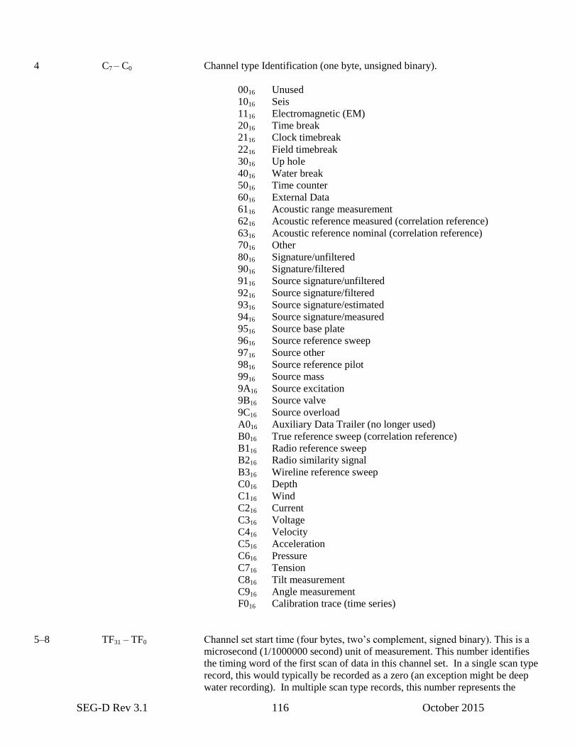
SEG-D Rev 3.1 116 October 2015
4 C7 – C0 Channel type Identification (one byte, unsigned binary).
0016 Unused
1016 Seis
1116 Electromagnetic (EM)
2016 Time break
2116 Clock timebreak
2216 Field timebreak
3016 Up hole
4016 Water break
5016 Time counter
6016 External Data
6116 Acoustic range measurement
6216 Acoustic reference measured (correlation reference)
6316 Acoustic reference nominal (correlation reference)
7016 Other
8016 Signature/unfiltered
9016 Signature/filtered
9116 Source signature/unfiltered
9216 Source signature/filtered
9316 Source signature/estimated
9416 Source signature/measured
9516 Source base plate
9616 Source reference sweep
9716 Source other
9816 Source reference pilot
9916 Source mass
9A16 Source excitation
9B16 Source valve
9C16 Source overload
A016 Auxiliary Data Trailer (no longer used)
B016 True reference sweep (correlation reference)
B116 Radio reference sweep
B216 Radio similarity signal
B316 Wireline reference sweep
C016 Depth
C116 Wind
C216 Current
C316 Voltage
C416 Velocity
C516 Acceleration
C616 Pressure
C716 Tension
C816 Tilt measurement
C916 Angle measurement
F016 Calibration trace (time series)
5–8 TF31 – TF0 Channel set start time (four bytes, two’s complement, signed binary). This is a
microsecond (1/1000000 second) unit of measurement. This number identifies
the timing word of the first scan of data in this channel set. In a single scan type
record, this would typically be recorded as a zero (an exception might be deep
water recording). In multiple scan type records, this number represents the
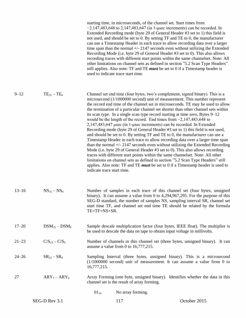
SEG-D Rev 3.1 117 October 2015
starting time, in microseconds, of the channel set. Start times from
−2,147,483,648 to 2,147,483,647 (in 1-μsec increments) can be recorded. In
Extended Recording mode (byte 29 of General Header #3 set to 1) this field is
not used, and should be set to 0. By setting TF and TE to 0, the manufacturer
can use a Timestamp Header in each trace to allow recording data over a larger
time span than the normal +/- 2147 seconds even without utilizing the Extended
Recording Mode (i.e. byte 29 of General Header #3 set to 0). This also allows
recording traces with different start points within the same channelset. Note: All
other limitations on channel sets as defined in section ”5.2 Scan Type Headers”
still applies. Also note: TF and TE must be set to 0 if a Timestamp header is
used to indicate trace start time.
9–12 TE31 – TE0 Channel set end time (four bytes, two’s complement, signed binary). This is a
microsecond (1/1000000 second) unit of measurement. This number represent
the record end time of the channel set in microseconds. TE may be used to allow
the termination of a particular channel set shorter than other channel sets within
its scan type. In a single scan type record starting at time zero, Bytes 9–12
would be the length of the record. End times from −2,147,483,648 to
2,147,483,647 μsec (in 1-μsec increments) can be recorded. In Extended
Recording mode (byte 29 of General Header #3 set to 1) this field is not used,
and should be set to 0. By setting TF and TE to 0, the manufacturer can use a
Timestamp Header in each trace to allow recording data over a larger time span
than the normal +/- 2147 seconds even without utilizing the Extended Recording
Mode (i.e. byte 29 of General Header #3 set to 0). This also allows recording
traces with different start points within the same channelset. Note: All other
limitations on channel sets as defined in section ”5.2 Scan Type Headers” still
applies. Also note: TF and TE must be set to 0 if a Timestamp header is used to
indicate trace start time.
13–16 NS31 – NS0 Number of samples in each trace of this channel set (four bytes, unsigned
binary). It can assume a value from 0 to 4,294,967,295. For the purpose of this
SEG-D standard, the number of samples NS, sampling interval SR, channel set
start time TF, and channel set end time TE should be related by the formula
TE=TF+NS×SR.
17–20 DSM31 – DSM0 Sample descale multiplication factor (four bytes, IEEE float). The multiplier is
be used to descale the data on tape to obtain input voltage in millivolts.
21–23 C/S23 – C/S0 Number of channels in this channel set (three bytes, unsigned binary). It can
assume a value from 0 to 16,777,215.
24–26 SR23 – SR0 Sampling Interval (three bytes, unsigned binary). This is a microsecond
(1/1000000 second) unit of measurement. It can assume a value from 0 to
16,777,215.
27 ARY7 – ARY0 Array Forming (one byte, unsigned binary). Identifies whether the data in this
channel set is the result of array forming.
0116 No array forming.
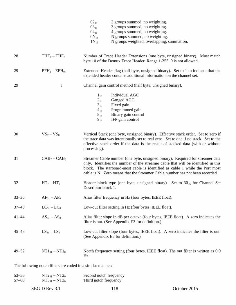
SEG-D Rev 3.1 118 October 2015
0216 2 groups summed, no weighting.
0316 3 groups summed, no weighting.
0416 4 groups summed, no weighting.
0N16 N groups summed, no weighting.
1N16 N groups weighted, overlapping, summation.
28 THE7 – THE0 Number of Trace Header Extensions (one byte, unsigned binary). Must match
byte 10 of the Demux Trace Header. Range 1-255. 0 is not allowed.
29 EFH3 – EFH0, Extended Header flag (half byte, unsigned binary). Set to 1 to indicate that the
extended header contains additional information on the channel set.
29 J Channel gain control method (half byte, unsigned binary).
116 Individual AGC
216 Ganged AGC
316 Fixed gain
416 Programmed gain
816 Binary gain control
916 IFP gain control
30 VS7 – VS0 Vertical Stack (one byte, unsigned binary). Effective stack order. Set to zero if
the trace data was intentionally set to real zero. Set to one if no stack. Set to the
effective stack order if the data is the result of stacked data (with or without
processing).
31 CAB7 – CAB0 Streamer Cable number (one byte, unsigned binary). Required for streamer data
only. Identifies the number of the streamer cable that will be identified in this
block. The starboard-most cable is identified as cable 1 while the Port most
cable is N. Zero means that the Streamer Cable number has not been recorded.
32 HT7 – HT0 Header block type (one byte, unsigned binary). Set to 3016 for Channel Set
Descriptor block 1.
33–36 AF31 – AF0 Alias filter frequency in Hz (four bytes, IEEE float).
37–40 LC31 – LC0 Low-cut filter setting in Hz (four bytes, IEEE float).
41–44 AS31 – AS0 Alias filter slope in dB per octave (four bytes, IEEE float). A zero indicates the
filter is out. (See Appendix E3 for definition.)
45–48 LS31 – LS0 Low-cut filter slope (four bytes, IEEE float). A zero indicates the filter is out.
(See Appendix E3 for definition.)
49–52 NT131 – NT10 Notch frequency setting (four bytes, IEEE float). The out filter is written as 0.0
Hz.
The following notch filters are coded in a similar manner:
53–56 NT231 – NT20 Second notch frequency
57–60 NT331 – NT30 Third notch frequency
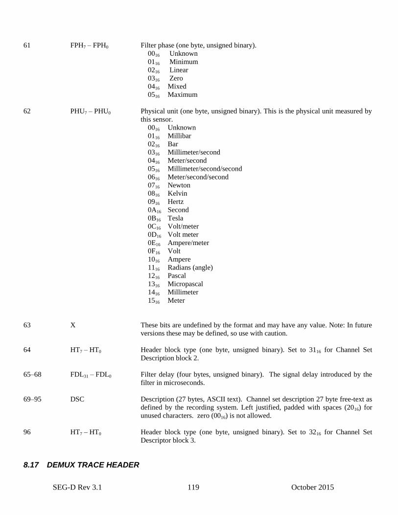
SEG-D Rev 3.1 119 October 2015
61 FPH7 – FPH0 Filter phase (one byte, unsigned binary).
0016 Unknown
0116 Minimum
0216 Linear
0316 Zero
0416 Mixed
0516 Maximum
62 PHU7 – PHU0 Physical unit (one byte, unsigned binary). This is the physical unit measured by
this sensor.
0016 Unknown
0116 Millibar
0216 Bar
0316 Millimeter/second
0416 Meter/second
0516 Millimeter/second/second
0616 Meter/second/second
0716 Newton
0816 Kelvin
0916 Hertz
0A16 Second
0B16 Tesla
0C16 Volt/meter
0D16 Volt meter
0E16 Ampere/meter
0F16 Volt
1016 Ampere
1116 Radians (angle)
1216 Pascal
1316 Micropascal
1416 Millimeter
1516 Meter
63 X These bits are undefined by the format and may have any value. Note: In future
versions these may be defined, so use with caution.
64 HT7 – HT0 Header block type (one byte, unsigned binary). Set to 3116 for Channel Set
Description block 2.
65–68 FDL31 – FDL0 Filter delay (four bytes, unsigned binary). The signal delay introduced by the
filter in microseconds.
69–95 DSC Description (27 bytes, ASCII text). Channel set description 27 byte free-text as
defined by the recording system. Left justified, padded with spaces (2016) for
unused characters. zero (0016) is not allowed.
96 HT7 – HT0 Header block type (one byte, unsigned binary). Set to 3216 for Channel Set
Descriptor block 3.
8.17 DEMUX TRACE HEADER
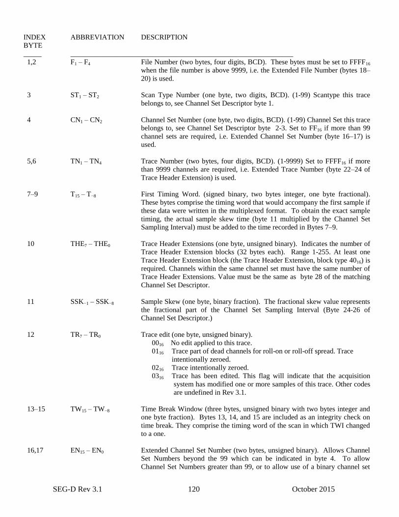
SEG-D Rev 3.1 120 October 2015
INDEX ABBREVIATION DESCRIPTION
BYTE
_____ ______________________________________________________________
1,2 F1 – F4 File Number (two bytes, four digits, BCD). These bytes must be set to FFFF16
when the file number is above 9999, i.e. the Extended File Number (bytes 18–
20) is used.
3 ST1 – ST2 Scan Type Number (one byte, two digits, BCD). (1-99) Scantype this trace
belongs to, see Channel Set Descriptor byte 1.
4 CN1 – CN2 Channel Set Number (one byte, two digits, BCD). (1-99) Channel Set this trace
belongs to, see Channel Set Descriptor byte 2-3. Set to FF16 if more than 99
channel sets are required, i.e. Extended Channel Set Number (byte 16–17) is
used.
5,6 TN1 – TN4 Trace Number (two bytes, four digits, BCD). (1-9999) Set to FFFF16 if more
than 9999 channels are required, i.e. Extended Trace Number (byte 22–24 of
Trace Header Extension) is used.
7–9 T15 – T−8 First Timing Word. (signed binary, two bytes integer, one byte fractional).
These bytes comprise the timing word that would accompany the first sample if
these data were written in the multiplexed format. To obtain the exact sample
timing, the actual sample skew time (byte 11 multiplied by the Channel Set
Sampling Interval) must be added to the time recorded in Bytes 7–9.
10 THE7 – THE0 Trace Header Extensions (one byte, unsigned binary). Indicates the number of
Trace Header Extension blocks (32 bytes each). Range 1-255. At least one
Trace Header Extension block (the Trace Header Extension, block type 4016) is
required. Channels within the same channel set must have the same number of
Trace Header Extensions. Value must be the same as byte 28 of the matching
Channel Set Descriptor.
11 SSK−1 – SSK−8 Sample Skew (one byte, binary fraction). The fractional skew value represents
the fractional part of the Channel Set Sampling Interval (Byte 24-26 of
Channel Set Descriptor.)
12 TR7 – TR0 Trace edit (one byte, unsigned binary).
0016 No edit applied to this trace.
0116 Trace part of dead channels for roll-on or roll-off spread. Trace
intentionally zeroed.
0216 Trace intentionally zeroed.
0316 Trace has been edited. This flag will indicate that the acquisition
system has modified one or more samples of this trace. Other codes
are undefined in Rev 3.1.
13–15 TW15 – TW−8 Time Break Window (three bytes, unsigned binary with two bytes integer and
one byte fraction). Bytes 13, 14, and 15 are included as an integrity check on
time break. They comprise the timing word of the scan in which TWI changed
to a one.
16,17 EN15 – EN0 Extended Channel Set Number (two bytes, unsigned binary). Allows Channel
Set Numbers beyond the 99 which can be indicated in byte 4. To allow
Channel Set Numbers greater than 99, or to allow use of a binary channel set
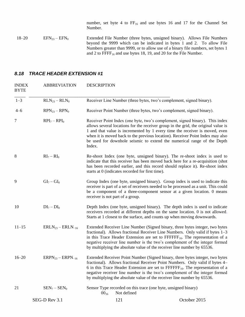
SEG-D Rev 3.1 121 October 2015
number, set byte 4 to FF16 and use bytes 16 and 17 for the Channel Set
Number.
18–20 EFN23 – EFN0 Extended File Number (three bytes, unsigned binary). Allows File Numbers
beyond the 9999 which can be indicated in bytes 1 and 2. To allow File
Numbers greater than 9999, or to allow use of a binary file numbers, set bytes 1
and 2 to FFFF16 and use bytes 18, 19, and 20 for the File Number.
8.18 TRACE HEADER EXTENSION #1
INDEX ABBREVIATION DESCRIPTION
BYTE
_____ ________________________________________________________________
1–3 RLN23 – RLN0 Receiver Line Number (three bytes, two’s complement, signed binary).
4–6 RPN23 – RPN0 Receiver Point Number (three bytes, two’s complement, signed binary).
7 RPI7 – RPI0 Receiver Point Index (one byte, two’s complement, signed binary). This index
allows several locations for the receiver group in the grid, the original value is
1 and that value is incremented by 1 every time the receiver is moved, even
when it is moved back to the previous location). Receiver Point Index may also
be used for downhole seismic to extend the numerical range of the Depth
Index.
8 RI7 – RI0 Re-shoot Index (one byte, unsigned binary). The re-shoot index is used to
indicate that this receiver has been moved back here for a re-acquisition (shot
has been recorded earlier, and this record should replace it). Re-shoot index
starts at 0 (indicates recorded for first time).
9 GI7 – GI0 Group Index (one byte, unsigned binary). Group index is used to indicate this
receiver is part of a set of receivers needed to be processed as a unit. This could
be a component of a three-component sensor at a given location. 0 means
receiver is not part of a group.
10 DI7 – DI0 Depth Index (one byte, unsigned binary). The depth index is used to indicate
receivers recorded at different depths on the same location. 0 is not allowed.
Starts at 1 closest to the surface, and counts up when moving downwards.
11–15 ERLN23 – ERLN−16 Extended Receiver Line Number (Signed binary, three bytes integer, two bytes
fractional). Allows fractional Receiver Line Numbers. Only valid if bytes 1–3
in this Trace Header Extension are set to FFFFFF16. The representation of a
negative receiver line number is the two’s complement of the integer formed
by multiplying the absolute value of the receiver line number by 65536.
16–20 ERPN23 – ERPN−16 Extended Receiver Point Number (Signed binary, three bytes integer, two bytes
fractional). Allows fractional Receiver Point Numbers. Only valid if bytes 4–
6 in this Trace Header Extension are set to FFFFFF16. The representation of a
negative receiver line number is the two’s complement of the integer formed
by multiplying the absolute value of the receiver line number by 65536.
21 SEN7 – SEN0 Sensor Type recorded on this trace (one byte, unsigned binary)
0016 Not defined
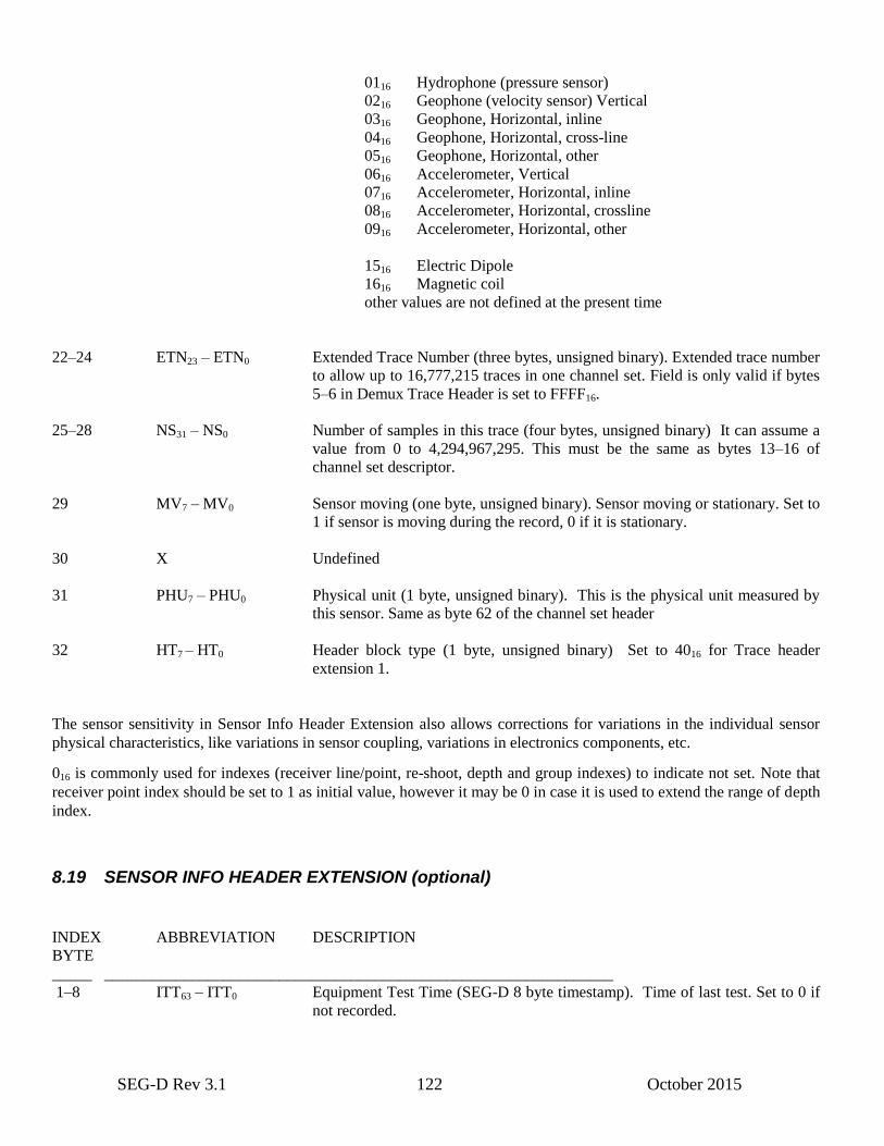
SEG-D Rev 3.1 122 October 2015
0116 Hydrophone (pressure sensor)
0216 Geophone (velocity sensor) Vertical
0316 Geophone, Horizontal, inline
0416 Geophone, Horizontal, cross-line
0516 Geophone, Horizontal, other
0616 Accelerometer, Vertical
0716 Accelerometer, Horizontal, inline
0816 Accelerometer, Horizontal, crossline
0916 Accelerometer, Horizontal, other
1516 Electric Dipole
1616 Magnetic coil
other values are not defined at the present time
22–24 ETN23 – ETN0 Extended Trace Number (three bytes, unsigned binary). Extended trace number
to allow up to 16,777,215 traces in one channel set. Field is only valid if bytes
5–6 in Demux Trace Header is set to FFFF16.
25–28 NS31 – NS0 Number of samples in this trace (four bytes, unsigned binary) It can assume a
value from 0 to 4,294,967,295. This must be the same as bytes 13–16 of
channel set descriptor.
29 MV7 – MV0 Sensor moving (one byte, unsigned binary). Sensor moving or stationary. Set to
1 if sensor is moving during the record, 0 if it is stationary.
30 X Undefined
31 PHU7 – PHU0 Physical unit (1 byte, unsigned binary). This is the physical unit measured by
this sensor. Same as byte 62 of the channel set header
32 HT7 – HT0 Header block type (1 byte, unsigned binary) Set to 4016 for Trace header
extension 1.
The sensor sensitivity in Sensor Info Header Extension also allows corrections for variations in the individual sensor
physical characteristics, like variations in sensor coupling, variations in electronics components, etc.
016 is commonly used for indexes (receiver line/point, re-shoot, depth and group indexes) to indicate not set. Note that
receiver point index should be set to 1 as initial value, however it may be 0 in case it is used to extend the range of depth
index.
8.19 SENSOR INFO HEADER EXTENSION (optional)
INDEX ABBREVIATION DESCRIPTION
BYTE
_____ ________________________________________________________________
1–8 ITT63 – ITT0 Equipment Test Time (SEG-D 8 byte timestamp). Time of last test. Set to 0 if
not recorded.
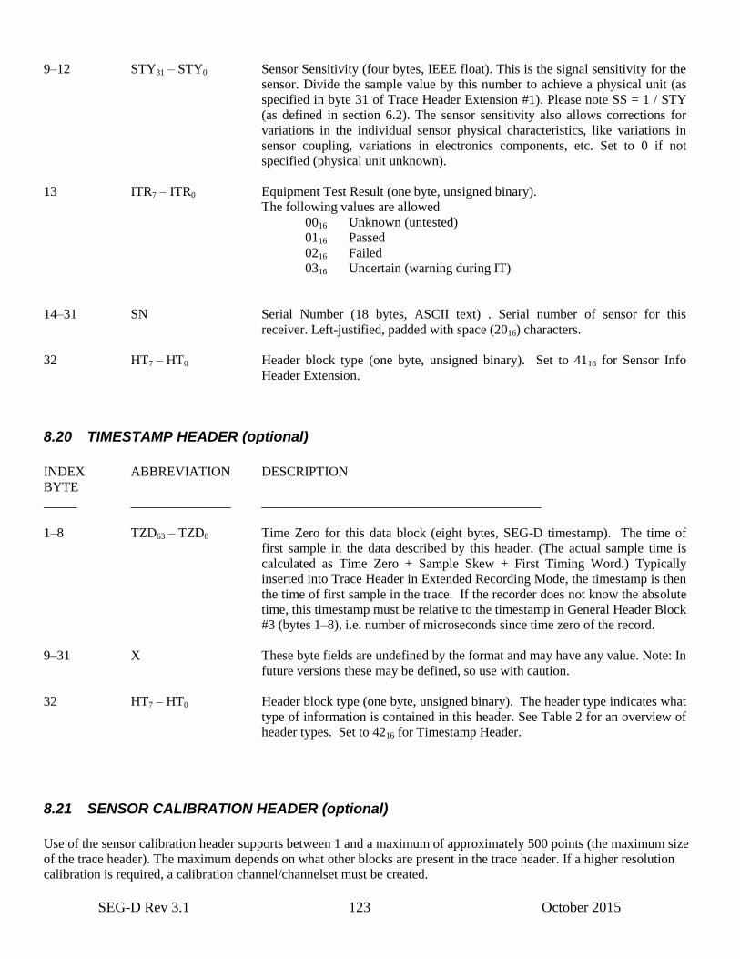
SEG-D Rev 3.1 123 October 2015
9–12 STY31 – STY0 Sensor Sensitivity (four bytes, IEEE float). This is the signal sensitivity for the
sensor. Divide the sample value by this number to achieve a physical unit (as
specified in byte 31 of Trace Header Extension #1). Please note SS = 1 / STY
(as defined in section 6.2). The sensor sensitivity also allows corrections for
variations in the individual sensor physical characteristics, like variations in
sensor coupling, variations in electronics components, etc. Set to 0 if not
specified (physical unit unknown).
13 ITR7 – ITR0 Equipment Test Result (one byte, unsigned binary).
The following values are allowed
0016 Unknown (untested)
0116 Passed
0216 Failed
0316 Uncertain (warning during IT)
14–31 SN Serial Number (18 bytes, ASCII text) . Serial number of sensor for this
receiver. Left-justified, padded with space (2016) characters.
32 HT7 – HT0 Header block type (one byte, unsigned binary). Set to 4116 for Sensor Info
Header Extension.
8.20 TIMESTAMP HEADER (optional)
INDEX ABBREVIATION DESCRIPTION
BYTE
_____ _______________ __________________________________________
1–8 TZD63 – TZD0 Time Zero for this data block (eight bytes, SEG-D timestamp). The time of
first sample in the data described by this header. (The actual sample time is
calculated as Time Zero + Sample Skew + First Timing Word.) Typically
inserted into Trace Header in Extended Recording Mode, the timestamp is then
the time of first sample in the trace. If the recorder does not know the absolute
time, this timestamp must be relative to the timestamp in General Header Block
#3 (bytes 1–8), i.e. number of microseconds since time zero of the record.
9–31 X These byte fields are undefined by the format and may have any value. Note: In
future versions these may be defined, so use with caution.
32 HT7 – HT0 Header block type (one byte, unsigned binary). The header type indicates what
type of information is contained in this header. See Table 2 for an overview of
header types. Set to 4216 for Timestamp Header.
8.21 SENSOR CALIBRATION HEADER (optional)
Use of the sensor calibration header supports between 1 and a maximum of approximately 500 points (the maximum size
of the trace header). The maximum depends on what other blocks are present in the trace header. If a higher resolution
calibration is required, a calibration channel/channelset must be created.
SEG-D Rev 3.1 124 October 2015
INDEX ABBREVIATION DESCRIPTION
BYTE
_____ _______________ __________________________________________
1–4 FR131 – FR10 Frequency 1 (four bytes, IEEE float). The frequency of first calibration value.
Set to 0.0 if not used.
5–8 AM131 – AM10 Amplitude 1 (four bytes, IEEE float). The amplitude of first calibration value.
9–12 PH131 – PH10 Phase 1 (four bytes, IEEE float). The phase of first calibration value.
13–16 FR231 – FR20 Frequency 2 (four bytes, IEEE float). The frequency of second calibration
value. Set to 0.0 if not used.
17–20 AM231 – AM20 Amplitude 2 (four bytes, IEEE float). The amplitude of second calibration
value.
21–24 PH231 – PH20 Phase 2 (four bytes, IEEE float). The phase of second calibration value.
25 CA7 – CA0 Calibration applied (one byte, unsigned binary). Set to 1 if calibration has
already been applied, i.e. the trace has been corrected with the calibration
function described by the values in the Sensor Calibration Header blocks, set to
0 if trace is not corrected. Note: Multiple Sensor Calibration Header blocks are
usually needed to describe a calibration function.
26–31 X Undefined
32 HT7 – HT0 Header block type (one byte, unsigned binary). The header type indicates what
type of information is contained in this header. See Table 2 for an overview of
header types. Set to 4316 for Sensor Calibration Header.
8.22 TIME DRIFT HEADER (optional)
This block may be used when data from sensors with drifting clocks are merged into one SEGD record. Data must be
clock drift corrected prior to creating a SEGD shot, i.e. SEGD only supports recording data with one single clock
reference system.
INDEX ABBREVIATION DESCRIPTION
BYTE
_____ ________________________________________________________________
1–8 TD63 – TD0 Time of deployment (eight bytes, SEG-D timestamp). Time of sensor unit
deployment, i.e. when time drift was measured before deployment.
9–16 TR63 – TR0 Time of retrieval (eight bytes, SEG-D timestamp). Time of sensor unit
retrieval, i.e. when the time drift was measured after retrieval.
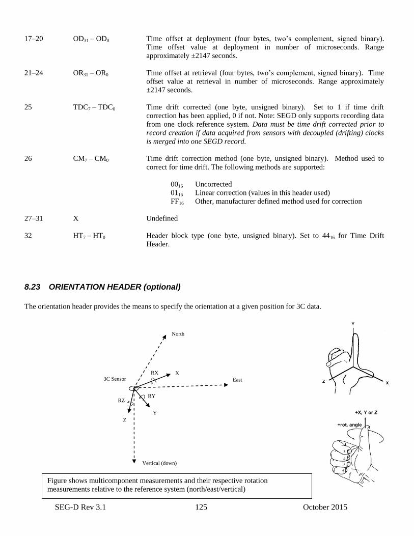
SEG-D Rev 3.1 125 October 2015
17–20 OD31 – OD0 Time offset at deployment (four bytes, two’s complement, signed binary).
Time offset value at deployment in number of microseconds. Range
approximately ±2147 seconds.
21–24 OR31 – OR0 Time offset at retrieval (four bytes, two’s complement, signed binary). Time
offset value at retrieval in number of microseconds. Range approximately
±2147 seconds.
25 TDC7 – TDC0 Time drift corrected (one byte, unsigned binary). Set to 1 if time drift
correction has been applied, 0 if not. Note: SEGD only supports recording data
from one clock reference system. Data must be time drift corrected prior to
record creation if data acquired from sensors with decoupled (drifting) clocks
is merged into one SEGD record.
26 CM7 – CM0 Time drift correction method (one byte, unsigned binary). Method used to
correct for time drift. The following methods are supported:
0016 Uncorrected
0116 Linear correction (values in this header used)
FF16 Other, manufacturer defined method used for correction
27–31 X Undefined
32 HT7 – HT0 Header block type (one byte, unsigned binary). Set to 4416 for Time Drift
Header.
8.23 ORIENTATION HEADER (optional)
The orientation header provides the means to specify the orientation at a given position for 3C data.
North
East
Vertical (down)
RZ RY
RX
Z
Y
X 3C Sensor
Figure shows multicomponent measurements and their respective rotation
measurements relative to the reference system (north/east/vertical)

SEG-D Rev 3.1 126 October 2015
X is defined as in-line, Y is cross-line and Z is vertical. Positive vertical is down. The rotation follows the right-hand rule.
RX is defined as rotation around X axis, RY around Y axis, and RZ around Z axis. Positive value as defined by right-hand
rule. This means the axis and positive direction for the rotation angles around the axis are given by the right hand, as
indicated in the figures above.
X axis will for cable acquisition (towed streamers, seabed cables etc.) be along the cable.
The rotation measurement in the sensor is expected to result in a rotation to the horizontal plane, however rotation to true
north will in many cases require an external measurement. This value is hence extracted to a separate field in the rotation
header, and may also be recorded as 0 if not available at the time of acquisition.
z
y
vertical
east
north
C
C
RRR
RRR
RRR
C
C
C x
333231
232221
131211 C
* (1)
The rotation described in bytes 1–16 in the orientation header must fulfill equation (1) above. The group index for
multicomponent data must hence be numbered such that
1 = X axis
2 = Y axis
3 = Z axis
INDEX ABBREVIATION DESCRIPTION
BYTE
_____ ________________________________________________________________
1–4 RX31 – RX0 Rotation angle around the X axis in radians (four bytes, IEEE float).
5–8 RY31 – RY0 Rotation angle around the Y axis in radians (four bytes, IEEE float).
9–12 RZ31 – RZ0 Rotation angle around the Z axis in radians (four bytes, IEEE float).
13–16 RO31 – RO0 Reference Orientation (four bytes, IEEE float). Rotation angle for the system
described in bytes 1–12 relative to true north, i.e. the rotation angle around the
Z axis for the X direction to point towards true north, This will be the cable
direction or housing orientation, depending of the value of byte 25. Recorded
as 0 if not applicable. If value is valid, byte 26 should be set to 1.
May be recorded as 0 if the value is unknown at the time of recording. The
value must then be made available to the processing/QC systems through other
means. Byte 26 should then be set to 0.
17–24 TS63 – TS0 Time Stamp (eight bytes, SEG-D timestamp). Timestamp for which the
rotation applies to, i.e. which sample the rotation applies to. Allows multiple
rotation measurements during a record. May be recorded as 0, the values then
applies to first sample in trace.
25 OT7 – OT0 Orientation Type horizontal plane (one byte, unsigned binary). The rotation
angle in bytes 9–12 is referenced to this coordinate system. The following
values are defined
SEG-D Rev 3.1 127 October 2015
0016 None/Unknown
0116 Earth true north
0216 Cable direction (e.g. marine/seabed
streamer)
0316 Sensor housing orientation
0416 Survey orientation
0516 Magnetic north
0916 Other
26 ROV7 – ROV0 Reference Orientation Valid (one byte, unsigned binary). Set to 1 if bytes 13–
16 contains a valid value, otherwise recorded as 0.
27 RA7 – RA0 Rotation Applied (one byte, unsigned binary). Set to 1 if rotation in bytes 1–12
has already been applied, otherwise recorded as 0. Allows recording of
orientation values for QC purposes even though the rotation has already been
done
28 RNA7 – RNA0 Rotation to North Applied (one byte, unsigned binary). Set to 1 if values in
traces has already been rotated to true north, otherwise recorded as 0. Rotation
in bytes 1–16 has been applied to trace values. Allows recording of orientation
values for QC purposes even though the rotation has already been done. If byte
28 is 1, byte 27 must also be set to 1.
29–31 X These bytes are undefined by the format and may have any value. Note: In
future versions these may be defined, so use with caution.
32 HT7 – HT0 Header block type (one byte, unsigned binary). Set to 6016 for Orientation
Header.
8.24 MEASUREMENT BLOCK (optional)
This block is used to standardize storage of different types of common measurements.
The Measurement Block may optionally be followed by a Position Block describing where the measurement was taken.
INDEX ABBREVIATION DESCRIPTION
BYTE
_____ ________________________________________________________________
1–8 TS63 – TS0 Time Stamp (eight bytes, SEG-D timestamp). Timestamp for the measurement.
Timestamp for time related measurements like Uphole time should be set to
time zero for record (same as timestamp in General Header #3) if they are
measuring the offset from start of record.
9–12 VA31 – VA0 Measurement value (four bytes, IEEE float). Value of the measurement. Set to
NAN (Not a number, 7fffffff16) if not defined.
SEG-D Rev 3.1 128 October 2015
13–16 MA31 – MA0 Maximum Value (four bytes, IEEE float). Maximum possible/allowed value of
measurement. Set to NAN (Not a number, 7fffffff16) if not defined.
17–20 MI31 – MI0 Minimum Value (four bytes, IEEE float). Minimum possible/allowed value of
measurement. Set to NAN (Not a number, 7fffffff16) if not defined.
21–22 QC15 – QC0 Quantity Class (two bytes, unsigned binary). Code representing the underlying
kind of measurement represented by GM1 (e.g. length, time, pressure, etc.).
Please refer to the Energistics Quantity Class table located at
http://www.seg.org/web/technical-standards-committee/wiki/-
/wiki/Main/SegMeasurements for the definition of codes. Example: Set to 1069
for “length”. Appendix F contains a snapshot of the Energistics Quantity Class
table.
23-24 UOM15- UOM0 Unit of Measure (two bytes, unsigned binary). Code of Unit of Measure for the
measurement VA. Please refer to the Energistics Unit of Measure table located
at http://www.seg.org/web/technical-standards-committee/wiki/-
/wiki/Main/SegMeasurements for the definition of codes. Example: Set to 2066
for “m (metre)”. Appendix F contains a snapshot of the Energistics Unit of
Measure table.
25-26 MD15 – MD0 Measurement Description code (two bytes, unsigned binary). Code
representing the detailed description of the measurement VA. Please refer to
the Measurement Description table located at
http://www.seg.org/web/technical-standards-committee/wiki/-
/wiki/Main/SegMeasurements for the definition of codes. Example set to
050216 for “Equipment height”.
27-31 X Undefined.
32 HT7 – HT0 Header block type (one byte, unsigned binary). Set to 6116 for Measurement
Block.
8.25 ELECTROMAGNETIC SRC/RECV DESC BLOCK (optional)
INDEX ABBREVIATION DESCRIPTION
BYTE
_____ ________________________________________________________________
1–3 LX23 – LX0 Equipment Dimension X direction (three bytes, unsigned binary). Length of
measurement equipment (e.g. antenna) in X (inline) direction in number of
centimeters (1/100 meters). Maximum length is 16777215 centimeters, or
approximately 16777 meters.
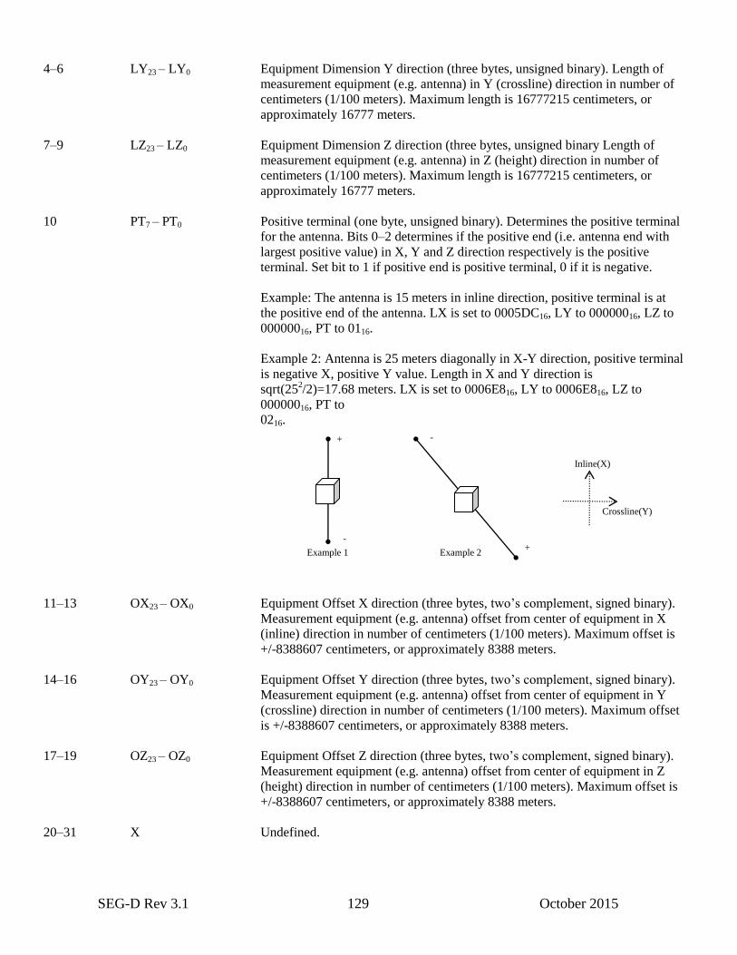
SEG-D Rev 3.1 129 October 2015
4–6 LY23 – LY0 Equipment Dimension Y direction (three bytes, unsigned binary). Length of
measurement equipment (e.g. antenna) in Y (crossline) direction in number of
centimeters (1/100 meters). Maximum length is 16777215 centimeters, or
approximately 16777 meters.
7–9 LZ23 – LZ0 Equipment Dimension Z direction (three bytes, unsigned binary Length of
measurement equipment (e.g. antenna) in Z (height) direction in number of
centimeters (1/100 meters). Maximum length is 16777215 centimeters, or
approximately 16777 meters.
10 PT7 – PT0 Positive terminal (one byte, unsigned binary). Determines the positive terminal
for the antenna. Bits 0–2 determines if the positive end (i.e. antenna end with
largest positive value) in X, Y and Z direction respectively is the positive
terminal. Set bit to 1 if positive end is positive terminal, 0 if it is negative.
Example: The antenna is 15 meters in inline direction, positive terminal is at
the positive end of the antenna. LX is set to 0005DC16, LY to 00000016, LZ to
00000016, PT to 0116.
Example 2: Antenna is 25 meters diagonally in X-Y direction, positive terminal
is negative X, positive Y value. Length in X and Y direction is
sqrt(252/2)=17.68 meters. LX is set to 0006E816, LY to 0006E816, LZ to
00000016, PT to
0216.
11–13 OX23 – OX0 Equipment Offset X direction (three bytes, two’s complement, signed binary).
Measurement equipment (e.g. antenna) offset from center of equipment in X
(inline) direction in number of centimeters (1/100 meters). Maximum offset is
+/-8388607 centimeters, or approximately 8388 meters.
14–16 OY23 – OY0 Equipment Offset Y direction (three bytes, two’s complement, signed binary).
Measurement equipment (e.g. antenna) offset from center of equipment in Y
(crossline) direction in number of centimeters (1/100 meters). Maximum offset
is +/-8388607 centimeters, or approximately 8388 meters.
17–19 OZ23 – OZ0 Equipment Offset Z direction (three bytes, two’s complement, signed binary).
Measurement equipment (e.g. antenna) offset from center of equipment in Z
(height) direction in number of centimeters (1/100 meters). Maximum offset is
+/-8388607 centimeters, or approximately 8388 meters.
20–31 X Undefined.
Crossline(Y)
Inline(X)
Example 1 Example 2
+
+ -
-
SEG-D Rev 3.1 130 October 2015
32 HT7 – HT0 Header block type (one byte, unsigned binary). Set to 4516 for Electromagnetic
Src/Recv Desc block
8.26 GENERAL TRAILER (Optional)
The general trailer consists of data block units of varying size. Each data block starts with a description block (32 bytes)
followed by data (either binary or ASCII) in a multiple of 32 bytes.
The content of the trailer data blocks is completely recording system defined. However, some types have been predefined
to simplify exchange of data. The predefined types (e.g. edits) can be found in table listed for Byte 1 in the General Trailer
Description block below.
Binary data padded with zeros (0016), ASCII data padded with spaces (2016), until 32 byte limit.
Layout of the general trailer will be like this:
[GT desc block (32 byte)][Block 1 (x*32 byte)][GTDB][Block 2][GTDB][Block 3]…
This is done to simplify appending data.
8.26.1 GENERAL TRAILER DESCRIPTION BLOCK (optional)
Field Description Bytes Start – end byte
1 Trailer Block type/id 1 1
2 ASCII/Binary data 1 2
Undefined (zero-filled) 2 3–4
3 Size (unsigned binary) 4 5–8
4 Description (ASCII) if type other 16 9–24
Undefined (zero-filled) 6 25–31
5 Header block type (7016) 1 32
INDEX ABBREVIATION DESCRIPTION
BYTE
_____ _____________ ____________________________________________________
1 BT7 – BT0 Block type, (one byte, unsigned binary). This describes the type of data in this
block.
0116 Edits
1016 Text comments
1116 Observer log
SEG-D Rev 3.1 131 October 2015
2016 P1 Processed position data
2116 P2 Raw positioning data
2216 P3 Land survey field data
2316 P5 Pipeline positioning data
2416 P6 3D seismic bin grid data
2516 P7 Well deviation data
2616 SPS Shell Processing Support data
2716 SEG-Y Extended Textual Stanza
A016 – FF16 Other (user defined)
2 AB7 – AB0 ASCII or binary (one byte, unsigned binary). States if data in this block is
binary or ASCII text.
0116 Binary
0216 ASCII
3–4 X Undefined, set to 0.
5–8 SI31 – SI0 Block size (four bytes, unsigned binary). Number of 32 byte blocks in this data
block. Block size in bytes = 32 * SI
9–24 DE Description (16 bytes, ASCII). A description of the contents of this data block.
Must be filled out if block type is Other/User defined (A016 – FF16). Unused
characters are filled with ASCII space (2016) characters.
25–31 X Undefined, set to 0.
32 HT7 – HT0 Header block type (one byte, unsigned binary). Set to 7016 for General Trailer
Description Block.
Note: All types of trailer records are optional.

SEG-D Rev 3.1 132 October 2015
Appendix A: Manufacturers of Seismic Field Recorders
Code No. Manufacturer Name and Address
01 Alpine Geophysical Associates, Inc. (Obsolete)
65 Oak St.
Norwood, New Jersey
02 Applied Magnetics Corporation (See 09)
75 Robin Hill Rd.
Goleta, California 93017
03 Western Geophysical Exploration Products (formerly Litton Resources Systems)
3600 Briarpark Drive,
Houston, Texas 77042
04 SIE, Inc. (Obsolete)
5110 Ashbrook
Houston, Texas 77036
05 Dyna-Tronics Mfg. Corporation (Obsolete)
5820 Star Ln., Box 22202
Houston, Texas 77027
06 Electronic Instrumentation, Inc. (Obsolete)
601 Dooley Rd., Box 34046
Dallas, Texas 75234
07 Halliburton Geophysical Services, Inc.,(formerly, Electro-Technical
Labs, Div. of Geosource, Inc.)
6909 Southwest Freeway
Houston, Texas 77074
08 Fortune Electronics, Inc. (Obsolete)
5606 Parkersburg Dr.
Houston, Texas 77036
09 Geo Space Corporation
7334 Gessner
Houston, Texas 77040
10 Leach Corporation (Obsolete)
405 Huntington Dr.
San Marino, California

SEG-D Rev 3.1 133 October 2015
11 Metrix Instrument Co. (Obsolete)
8200 Westglen
Box 36501
Houston, Texas 77063
12 Redcor Corporation (Obsolete)
7800 Deering Ave., Box 1031
Canoga Park, California 91304
13 Sercel (Societe d'Etudes, Recherches Et Constructions Electroniques)
25 X, 44040 Nantes Cedex,
France
14 Scientific Data Systems (SDS), (Obsolete)
1649 Seventeenth St.
Santa Monica, California 90404
15 Texas Instruments, Inc.
P.O. Box 1444
Houston, Texas 77001
17 GUS Manufacturing, Inc.
P.O. Box 10013
El Paso, Texas 79991
18 Input/Output, Inc.
12300 Parc Crest Dr.
Stafford, Texas 77477
19 Geco-Prakla
Transition Zone Product Development
(formerly Terra Marine Engineering)
10420 Miller Road
Dallas, Texas 75238
20 Fairfield Industries, Incorporated
10627 Kinghurst
Houston, Texas 77099
22 Geco-Prakla
Buckingham Gate, Gatwick Airport
West Sussex, RH6 ONZ, UK
31 Japex Geoscience Institute 1991
Akasaka Twin Towers Bldg. 2;
2-17-22, Akasaka
Minato-ku; Tokyo 107, Japan
32 Halliburton Geophysical Services, Inc. 1991
6909 Southwest Freeway
Houston, Texas 77074

SEG-D Rev 3.1 134 October 2015
33 Compuseis, Inc. 1993
8920 Business Park Dr, Ste 275,
Austin, Texas 78759
34 Syntron, Inc. 1993
17200 Park Row
Houston, Texas 77084
35 Syntron Europe Ltd. 1993
Birchwood Way
Cotes Park Industrial Estates
Somercotes, Alfreton,
Dergyshire DE55 4QQ, U.K.
36 Opseis 1994
7700 E. 38th St.
Tulsa, OK 74145
39 Grant Geophysical 1995
16850 Park Row
Houston, Tx 77084
40 Geo-X 1996
Suite 900, 425 1st St SW
Calgary, Alberta, Canada T2P3L8
41 PGS Inc. 2001
16010, Barkers Point Lane,
Houston
Texas 77079
42 SeaMap UK Ltd. 2003
Unit 31
The Maltings
Charlton Estate
Shepton Mallet BA4 5QE
UK
43 Hydroscience 2004
Hydroscience Technologies, Inc.
5101 Airport Road
Mineral Wells,
Texas 77478
USA
44 JSC 2006
“SPECIAL DESIGN BUREAU FOR SEISMIC INSTRUMENTATION”
129, Krainyaya Str.,
410019 Saratov,
RUSSIA
45 Fugro 2006
Hoffsveien 1C
N-0213 Oslo

SEG-D Rev 3.1 135 October 2015
NORWAY
46 ProFocus Systems AS 2006
Spelhaugen 20
5147 Fyllingsdalen
NORWAY
47 Optoplan AS 2008
Haakon VII’s gate 17
7041 Trondheim
NORWAY
48 Wireless Seismic Inc 2008
12996 Somerset Drive
Grass Valley, CA 95945
USA
49 AutoSeis 2010
2101 Midway Road Suite 310
Carrolton, TX 75006
USA
50 INOVA Geophysical, Inc. 2011
12200 Parc Crest Drive
Stafford, TX 77477
USA
51 Verif-i Ltd. 2011
23 Wood Lane
Sonning Common, RG4 9SJ
UK
52 Troika International 2012
14b Chapel Place
Tunbridge Wells, Kent, TN1 1YQ
UK
53 MagSeis AS 2012
Teatergaten 35
5010 Bergen
Norway
54 Seismic Instruments, Inc 2013
7501 N, Capital of Texas Hwy
Building A, Suite 150
Austin, TX 78731
USA
55 TGS 2014
1 The Crescent
Surbiton
SEG-D Rev 3.1 136 October 2015
Surrey, KT6 4BN
UK
56 Hewlett Packard Co 2014
1040 NE Circle Blvd
M/S 422C
Corvallis, OR 97330
USA
57 Modern Seismic Technology, LLC 2014
8, Rucheinaya, Str.
353477 Gelendzhik
RUSSIA
58 OCTIO 2014
Boehmergaten 44
N-5057 Bergen
NORWAY
59 inApril AS 2015
Per Krohgs Vei 4 A
N-1065 Oslo
NORWAY

SEG-D Rev 3.1 137 October 2015
Appendix B: Glossary
Attribute – A named item of information or data pertaining to an object.
Base scan interval – The time between timing words. A base scan interval usually contains one scan but under
some conditions may contain multiple subscans.
Beginning of tape mark (BOT) – An indelible mark (e.g., reflector) near the beginning of the tape that indicates
the start of the region in which recorded data is permitted.
Block – The data between gaps on tape. On modern tape devices block may be a logical marks only, not an
actual gap on the tape. A block usually refers to the smallest amount of data possible to read from the device.
Channel set – One or more channels sampled at the same sampling interval and containing the same filter, fixed
gain, and other fixed parameter information.
Channel set descriptor – A unit of the scan type header describing the parameters of a channel set.
Data recording method – The arrangement of bits to represent samples on tape.
End of data flag (EOD) – A special record or condition on the tape used to indicate the end of data on the tape.
End of file mark (EOF) – A special record or condition on the tape that indicates the end of a tape file. Also
called File Mark.
End of tape warning (ETW) – An indelible mark (e.g., reflector), located a required minimum distance from
the physical end of the tape that serves as a warning.
Field record – The data between two filemarks on media that supports this (e.g. tape). The field record may
consists of multiple SEG-D records. For media without filemarks the field record equals a SEG-D record. (See
also File)
File – Literally, it is all of the blocks between file marks. The term Field File is sometimes used instead of File.
It is all data recorded from a one or more energy impulses or sweeps, stored in one or more SEG-D records. It
may also be the sum of a number of energy impulses or sweeps, or data recorded without any source actions.
(See also Field record.)
Filemark – A special record or state of a media index that indicates the end of a physical file.
Format Data – recording method combined with a multiplexed/demultiplexed indicator (see general header
Bytes 3 and 4).
General header – The first header in the header block. It contains information common to the entire record.
Index byte – The byte number of some particular parameter within the general or scan type header.
Organization code – A number assigned by the Petroleum Open Standards Consortium (POSC) to an
organization that identifies the organization and represents schemas and dictionaries defined and administered by
the organization.
Packed BCD – Binary coded decimal digits represented by four data bits.
Partition – An independent recording area resulting from physical formatting of the media that can be mounted
as though it were a single volume.
Physical blocks (on tape) – A collection of contiguous bytes recorded as a unit on a longitudinal tape or a track
set on helical scan tape. Physical blocks on longitudinal tape are separated by interblock gaps.
Record – A SEG-D record is a collection of data traces and meta-data describing those traces. It is also allowed
to create a record with the meta-data only. The record consists of a header (mandatory), data traces and a record
trailer. Sometimes the terms Shot record or Seismic record is used to describe a SEG-D record.
Sample skew – The fraction of the base scan interval between the timing word and the actual time the sample
was taken in a base scan interval (not related to position on tape).
Sampling interval – The interval between readings such as the time between successive samples of a digital
seismic trace.
Scan – One complete sequence of events, such as sampling all channels. Data recorded during a base scan
interval.
Scan interval – The interval between readings of all samples contained in a scan type.
Scan type – One complete set of channel sets which make up a scan. A seismic record contains multiple scans,
and may or may not contain more than one scan type.

SEG-D Rev 3.1 138 October 2015
Scan type header – A header containing one or more channel set descriptors and the skew information.
Schema – A formalized description of the encoding of information defined by a logical model, typically in terms
of a data model.
Storage set – An ordered set of storage units, the position in the set is specified in the storage unit label.
Storage unit – A logical volume of data containing on or more logical files.
Subscan – A set of samples containing one sample for each channel in a channel set.
Tape file – Is the data contained between two File Marks or between an File Mark at its beginning and an EOD
at its end. A typical implementation of EOD is an empty tape file, i.e., two consecutive File Marks. Some
systems implement EOD as two or more (possibly many) File Marks.
Tape record – A sequence of data bytes treated as a unit by the tape I/O subsystem. The application provides
the number of bytes in the tape record when writing and is returned the number of bytes in the tape record when
reading. A tape record has an identifiable beginning on the tape, which need not be on the boundary of a
physical block, and which is locatable by the tape I/O subsystem.
Time break window – Time interval in which time break is expected. If time break does not occur by the end of
the window, internal time break is generated.
Trace - A record of one seismic channel within a scan type. A collection of a sequential set of points from one
seismic channel.
Trace block - A block containing the data of one trace or a part of a trace with constant parameters.

SEG-D Rev 3.1 139 October 2015
Appendix C: API Producer Organization Code
C.1 Scope
Table 1 below contains a list of organization codes assigned by the Petrotechnical Open Standards Consortium (POSC)
for use in API Recommended Practice 66. Several of the organization codes in this appendix are historical in nature
and reflect the well log origins of API Recommended Practice 66.
This specification was originally prepared by the Subcommittee on Standard Format for Digital Well data. In June 1996
it was designated a recommended practice by the American Petroleum Institute [API] Exploration & Production
Department's Executive Committee on Drilling and Production Practices. In June 1998 stewardship of the document
was transferred from API to Petroleum Open Standards Consortium [POSC]. This organization was relaunched as
Energistics in December 2006.
C.2 Assignment of Organization Codes
Organization codes are assigned by Energistics, which maintains the current list of codes. To request a new organization
code, contact:
Energistics
One Sugar Creek Center Blvd.
Suite 1075
Sugar Land, TX 77478 USA
+1 281 243-2121 telephone
+1 281 243-2132 fax
http://www.energistics.org/
The following is copied from
http://w3.energistics.org/RP66/V2/Toc/main.html
This document, POSC RP66 V2, is a specification of Petrotechnical Open Standards Consortium.
This specification is based on and is equivalent in content to the document Recommended Practices for Exploration and
Production Data Digital Interchange: API RECOMMENDED PRACTICE 66, V2: Second Edition, June 1996 published
by the American Petroleum Institute (API). The acronym RP66V2 is retained for historical reasons; POSC does not
designate specifications as "Recommended Practices".
The following table is copied from
http://www.energistics.org/rp66-organization-codes
Last Updated 5 Oct 2011
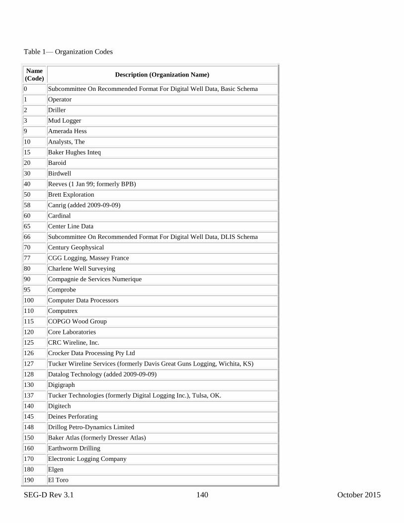
SEG-D Rev 3.1 140 October 2015
Table 1— Organization Codes
Name
(Code) Description (Organization Name)
0 Subcommittee On Recommended Format For Digital Well Data, Basic Schema
1 Operator
2 Driller
3 Mud Logger
9 Amerada Hess
10 Analysts, The
15 Baker Hughes Inteq
20 Baroid
30 Birdwell
40 Reeves (1 Jan 99; formerly BPB)
50 Brett Exploration
58 Canrig (added 2009-09-09)
60 Cardinal
65 Center Line Data
66 Subcommittee On Recommended Format For Digital Well Data, DLIS Schema
70 Century Geophysical
77 CGG Logging, Massey France
80 Charlene Well Surveying
90 Compagnie de Services Numerique
95 Comprobe
100 Computer Data Processors
110 Computrex
115 COPGO Wood Group
120 Core Laboratories
125 CRC Wireline, Inc.
126 Crocker Data Processing Pty Ltd
127 Tucker Wireline Services (formerly Davis Great Guns Logging, Wichita, KS)
128 Datalog Technology (added 2009-09-09)
130 Digigraph
137 Tucker Technologies (formerly Digital Logging Inc.), Tulsa, OK.
140 Digitech
145 Deines Perforating
148 Drillog Petro-Dynamics Limited
150 Baker Atlas (formerly Dresser Atlas)
160 Earthworm Drilling
170 Electronic Logging Company
180 Elgen
190 El Toro

SEG-D Rev 3.1 141 October 2015
200 Empire
205 Encom Technology, Ltd.
206 Ensigh Geophysics, Ltd.
208 Epoch (merged with Canrig, Nov 2008; added 2009-09-09)
210 Frontier
215 Geolog
217 Geoshare
218 GEO·X Systems Ltd.
220 G O International
230 Gravilog
240 Great Guns Servicing
250 Great Lakes Petroleum Services
260 GTS
268 Guardian Data Seismic Pty. Ltd.
270 Guns
280 Halliburton Logging
285 Horizon Production Logging
290 Husky
293 INOVA Geophysical (added 2011-01-03)
295 Input/Output, Inc.
300 Jetwell
305 Landmark Graphics
310 Lane Wells
315 Logicom Computer Services (UK) Ltd
320 Magnolia
330 McCullough Tool
332 Mitchell Energy Corporation
335 Paradigm Geophysical (formerly Mincom Pty Ltd)
337 DPTS Limited (formerly MR-DPTS Limited, changed as of 2008-08-12)
338 NRI On-Line Inc
339 Oilware, Inc.
340 Pan Geo Atlas
342 Pathfinder Energy Services
345 Perfco
350 Perfojet Services
360 Perforating Guns of Canada
361 Petcom, Inc.
362 Petroleum Exploration Computer Consultants, Ltd.
363 Petrologic Limited
366 Phillips Petroleum Company
367 Phoenixdata Services Pty Ltd.

SEG-D Rev 3.1 142 October 2015
368 Petroleum Geo-Services (PGS)
370 Petroleum Information
380 Petrophysics
390 Pioneer
392 The Practical Well Log Standards Group
395 IHS Energy Log Services (formerly Q. C. Data Collectors)
400 Ram Guns
410 Riley's Datashare
418 RODE
420 Roke
430 Sand Surveys
440 Schlumberger
450 Scientific Software
460 Seismograph Service
462 SEGDEF
463 SEG Technical Standards High Density Media Format Subcommittee
464 Shell Services Company
465 Stratigraphic Systems, Inc.
466 Spectrum ASA
467 Sperry-Sun Drilling Services
468 SEPTCO
469 Sercel, Inc.
470 Triangle
471 Thrubit Logging(added 2009-09-09)
475 Troika International
480 Welex
490 Well Reconnaissance
495 Wellsite Information Transfer Specification (WITS)
500 Well Surveys
510 Western
520 Westronics
525 Winters Wireline
530 Wireline Electronics
540 Worth Well
560 Z & S Consultants Limited
999 Reserved for local schemas
1000 Energistics (formerly POSC, changed as of 2006-11-06
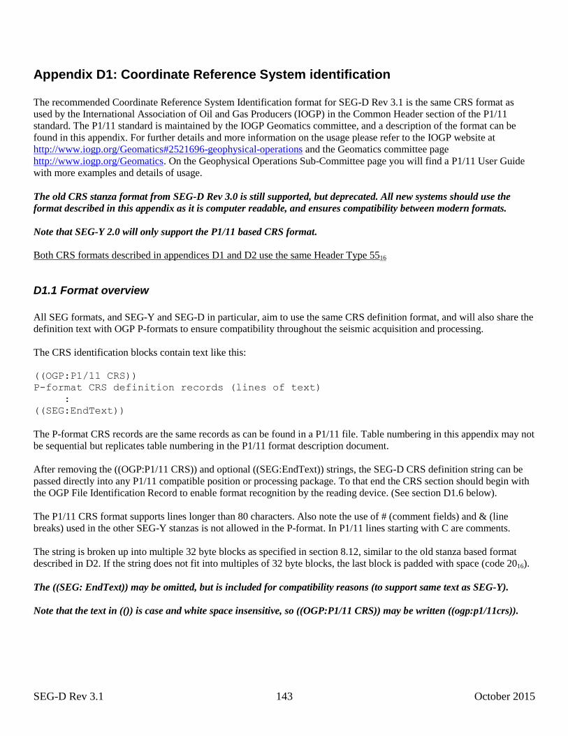
SEG-D Rev 3.1 143 October 2015
Appendix D1: Coordinate Reference System identification
The recommended Coordinate Reference System Identification format for SEG-D Rev 3.1 is the same CRS format as
used by the International Association of Oil and Gas Producers (IOGP) in the Common Header section of the P1/11
standard. The P1/11 standard is maintained by the IOGP Geomatics committee, and a description of the format can be
found in this appendix. For further details and more information on the usage please refer to the IOGP website at
http://www.iogp.org/Geomatics#2521696-geophysical-operations and the Geomatics committee page
http://www.iogp.org/Geomatics. On the Geophysical Operations Sub-Committee page you will find a P1/11 User Guide
with more examples and details of usage.
The old CRS stanza format from SEG-D Rev 3.0 is still supported, but deprecated. All new systems should use the
format described in this appendix as it is computer readable, and ensures compatibility between modern formats.
Note that SEG-Y 2.0 will only support the P1/11 based CRS format.
Both CRS formats described in appendices D1 and D2 use the same Header Type 5516
D1.1 Format overview
All SEG formats, and SEG-Y and SEG-D in particular, aim to use the same CRS definition format, and will also share the
definition text with OGP P-formats to ensure compatibility throughout the seismic acquisition and processing.
The CRS identification blocks contain text like this:
((OGP:P1/11 CRS))
P-format CRS definition records (lines of text)
:
((SEG:EndText))
The P-format CRS records are the same records as can be found in a P1/11 file. Table numbering in this appendix may not
be sequential but replicates table numbering in the P1/11 format description document.
After removing the ((OGP:P1/11 CRS)) and optional ((SEG:EndText)) strings, the SEG-D CRS definition string can be
passed directly into any P1/11 compatible position or processing package. To that end the CRS section should begin with
the OGP File Identification Record to enable format recognition by the reading device. (See section D1.6 below).
The P1/11 CRS format supports lines longer than 80 characters. Also note the use of # (comment fields) and & (line
breaks) used in the other SEG-Y stanzas is not allowed in the P-format. In P1/11 lines starting with C are comments.
The string is broken up into multiple 32 byte blocks as specified in section 8.12, similar to the old stanza based format
described in D2. If the string does not fit into multiples of 32 byte blocks, the last block is padded with space (code 2016).
The ((SEG: EndText)) may be omitted, but is included for compatibility reasons (to support same text as SEG-Y).
Note that the text in (()) is case and white space insensitive, so ((OGP:P1/11 CRS)) may be written ((ogp:p1/11crs)).
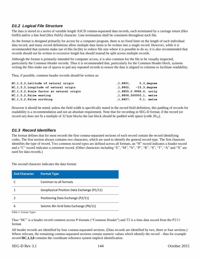
SEG-D Rev 3.1 144 October 2015
D1.2 Logical File Structure
The data is stored in a series of variable length ASCII comma-separated data records, each terminated by a carriage return (Hex
0x0D) and/or a line feed (Hex 0x0A) character. Line termination shall be consistent throughout each file.
As the format is designed primarily for access by a computer program, there is no fixed limit on the length of each individual
data record, and many record definitions allow multiple data items to be written into a single record. However, while it is
recommended that systems make use of this facility to reduce file size where it is possible to do so, it is also recommended that
records should not be written to excessive length but should instead be split across multiple records.
Although the format is primarily intended for computer access, it is also common for the file to be visually inspected,
particularly the Common Header records. Thus it is recommended that, particularly for the Common Header block, systems
writing the files make use of spaces to pad any repeated records to ensure the data is aligned in columns to facilitate readability.
Thus, if possible, common header records should be written as:
HC,1,5,2,Latitude of natural origin........................,1,8801, 0,3,degree HC,1,5,2,Longitude of natural origin.......................,1,8802, -15,3,degree HC,1,5,2,Scale factor at natural origin....................,1,8805,0.9996,4, unity HC,1,5,2,False easting.....................................,1,8806,500000,1, metre HC,1,5,2,False northing....................................,1,8807, 0,1, metre
However it should be noted, unless the field width is specifically stated in the record field definition, this padding of records for
readability is a recommendation and not an absolute requirement. Note that for recording in SEG-D format, if the record (or
record set) does not fit a multiple of 32 byte blocks the last block should be padded with space (code 2016).
D1.3 Record Identifiers
The format defines that for most records the first comma-separated sections of each record contain the record identifying
codes. The first section always contains two characters, which are used to identify the general record type. The first character
identifies the type of record. Two common record types are defined across all formats, an “H” record indicates a header record
and a “C” record indicates a comment record. (Other characters including “E”, “M”, “N”, “P”, “R”, “S”, “T”, “A” and “X” are
used for data records.)
The second character indicates the data format:
2nd Character Format Type
C Common to all formats
1 Geophysical Position Data Exchange (P1/11)
2 Positioning Data Exchange (P2/11)
6 Seismic Bin Grid Data Exchange (P6/11)
Table 1: Format Types
Thus “HC” is a header record common across P-formats (“Common Header”) and T2 is a time data record from the P2/11
format.
All header records are identified by four comma-separated sections. (Data records are identified by two, three or four sections.)
Where relevant, the remaining comma-separated sections contain numeric values which identify the record – thus for example
record HC,1,3,0 contains the coordinate reference system implicit identification.

SEG-D Rev 3.1 145 October 2015
D1.4 Data Types used in the Format Definition
The following data types are used in the P1/11 format definition:
Name Description Conditions Value
Single Items
Integer Integer Number 341234
Float Floating Point Number 12.345678
Engineering Engineering Format Floating Point Number
1.23456E+03
Text Free Text L J n: Specifies the text should be left justified to the minimum width specified
Hello World
Description Record Description A text field left justified to 50 characters
Project Name
Date Date YYYY:MM:DD
Time Time HH:MM:SS
Note: Time can be recorded to any number of decimal places, as defined by the data recorded
Variant Any of the above data types
Lists (All of general format xx&xx&xx&xx)
Integer List List of Integer Numbers 12&34&56&78&9
Float List List of Floats 1.23&4.56&6.78
Engineering List List of Engineering 1.23456E3&7.89012E4&3.456E2
Text List List of Text Hello&world
Variant List List of Items of Variant format 1&Hello&1.45
Table 2: Format Data Types
For some fields the data type is given as “Variant”. This may take the form of any of the data types.
The codes used to define variant data stored within the data records are defined in Table 4 below.
All individual text fields should contain only ASCII characters in the range 32 (Hex 0x20) to 126
(Hex 0x7E) and the following characters are additionally not to be used to ensure format rigidity:

SEG-D Rev 3.1 146 October 2015
Character Description ASCII Code Usage in Format
, Comma 44 Separates Fields
; Semi Colon 59 Separates items in a Standard Record Extension Definition and Record Extension Fields
: Colon 58 Separates items in Date and Time fields
& Ampersand 38 Separates items in a Variant List
Table 3: Reserved Characters
Where use of reserved characters is unavoidable, for example to refer to a parameter name exactly as used by its source, an
escape character sequence can be used.
Any character can be expressed as a \u followed by the 4 digit hexadecimal value written in uppercase. For example: , is escaped with \u002C
; is escaped with \u003B
: is escaped with \u003A
& is escaped with \u0026
An escape character which does not start with \u00 is interpreted as the start of an UTF-8 character sequence.
D1.5 Record Data Types [DATATYPEREF]
The following codes are used within the format to define the data format of an item that can be of variant type:
Code Name Format Example Comments
General
1 Integer XX 23453
2 Floating Point Number XX.XX 12.345
3 Engineering Format Floating Point Number
XX.XXE±NN 1.23456E+03
4 Text ABC Hello World
5 Boolean X 1 1 if True,0 if False
Time
10 Relative Time D:HH:MM:SS.SS 0:23:34:12.22
11 Date and Time YYYY:MM:DD:HH:MM:SS.SS 2010:04:20:23:34:12.22
12 Julian Day and Time YYYY:JDD:HH:MM:SS.SS 2010:134:23:34:12.22
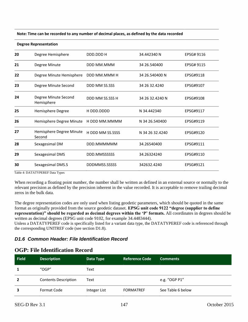
SEG-D Rev 3.1 147 October 2015
Note: Time can be recorded to any number of decimal places, as defined by the data recorded
Degree Representation
20 Degree Hemisphere DDD.DDD H 34.442340 N EPSG# 9116
21 Degree Minute DDD MM.MMM 34 26.540400 EPSG# 9115
22 Degree Minute Hemisphere DDD MM.MMM H 34 26.540400 N EPSG#9118
23 Degree Minute Second DDD MM SS.SSS 34 26 32.4240 EPSG#9107
24 Degree Minute Second Hemisphere
DDD MM SS.SSS H 34 26 32.4240 N EPSG#9108
25 Hemisphere Degree H DDD.DDDD N 34.442340 EPSG#9117
26 Hemisphere Degree Minute H DDD MM.MMMM N 34 26.540400 EPSG#9119
27 Hemisphere Degree Minute Second
H DDD MM SS.SSSS N 34 26 32.4240 EPSG#9120
28 Sexagesimal DM DDD.MMMMMM 34.26540400 EPSG#9111
29 Sexagesimal DMS DDD.MMSSSSSS 34.26324240 EPSG#9110
30 Sexagesimal DMS.S DDDMMSS.SSSSS 342632.4240 EPSG#9121
Table 4: DATATYPEREF Data Types
When recording a floating point number, the number shall be written as defined in an external source or normally to the
relevant precision as defined by the precision inherent in the value recorded. It is acceptable to remove trailing decimal
zeros in the bulk data.
The degree representation codes are only used when listing geodetic parameters, which should be quoted in the same
format as originally provided from the source geodetic dataset. EPSG unit code 9122 “degree (supplier to define
representation)” should be regarded as decimal degrees within the ‘P’ formats. All coordinates in degrees should be
written as decimal degrees (EPSG unit code 9102, for example 34.4483444). Unless a DATATYPEREF code is specifically listed for a variant data type, the DATATYPEREF code is referenced through
the corresponding UNITREF code (see section D1.8).
D1.6 Common Header: File Identification Record
OGP: File Identification Record
Field Description Data Type Reference Code Comments
1 “OGP” Text
2 Contents Description Text e.g. “OGP P1”
3 Format Code Integer List FORMATREF See Table 6 below
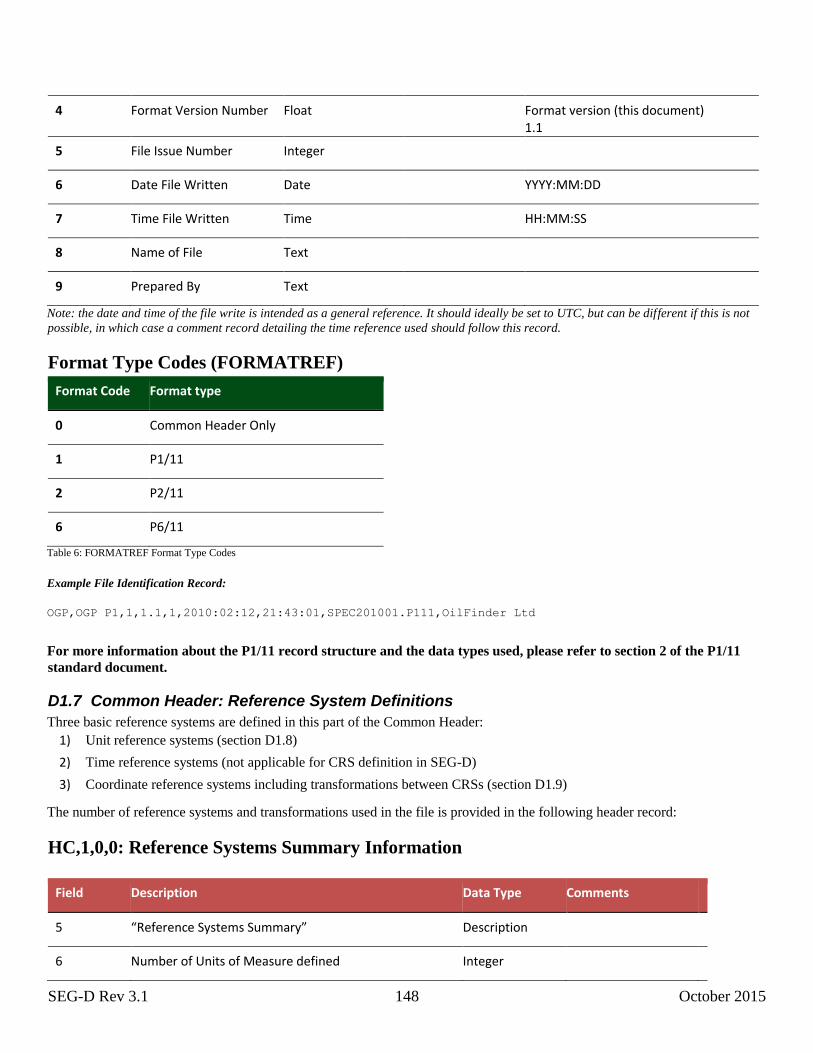
SEG-D Rev 3.1 148 October 2015
4 Format Version Number Float Format version (this document) 1.1
5 File Issue Number Integer
6 Date File Written Date YYYY:MM:DD
7 Time File Written Time HH:MM:SS
8 Name of File Text
9 Prepared By Text
Note: the date and time of the file write is intended as a general reference. It should ideally be set to UTC, but can be different if this is not
possible, in which case a comment record detailing the time reference used should follow this record.
Format Type Codes (FORMATREF)
Format Code Format type
0 Common Header Only
1 P1/11
2 P2/11
6 P6/11
Table 6: FORMATREF Format Type Codes
Example File Identification Record:
OGP,OGP P1,1,1.1,1,2010:02:12,21:43:01,SPEC201001.P111,OilFinder Ltd
For more information about the P1/11 record structure and the data types used, please refer to section 2 of the P1/11
standard document.
D1.7 Common Header: Reference System Definitions
Three basic reference systems are defined in this part of the Common Header:
1) Unit reference systems (section D1.8)
2) Time reference systems (not applicable for CRS definition in SEG-D)
3) Coordinate reference systems including transformations between CRSs (section D1.9)
The number of reference systems and transformations used in the file is provided in the following header record:
HC,1,0,0: Reference Systems Summary Information
Field Description Data Type Comments
5 “Reference Systems Summary” Description
6 Number of Units of Measure defined Integer
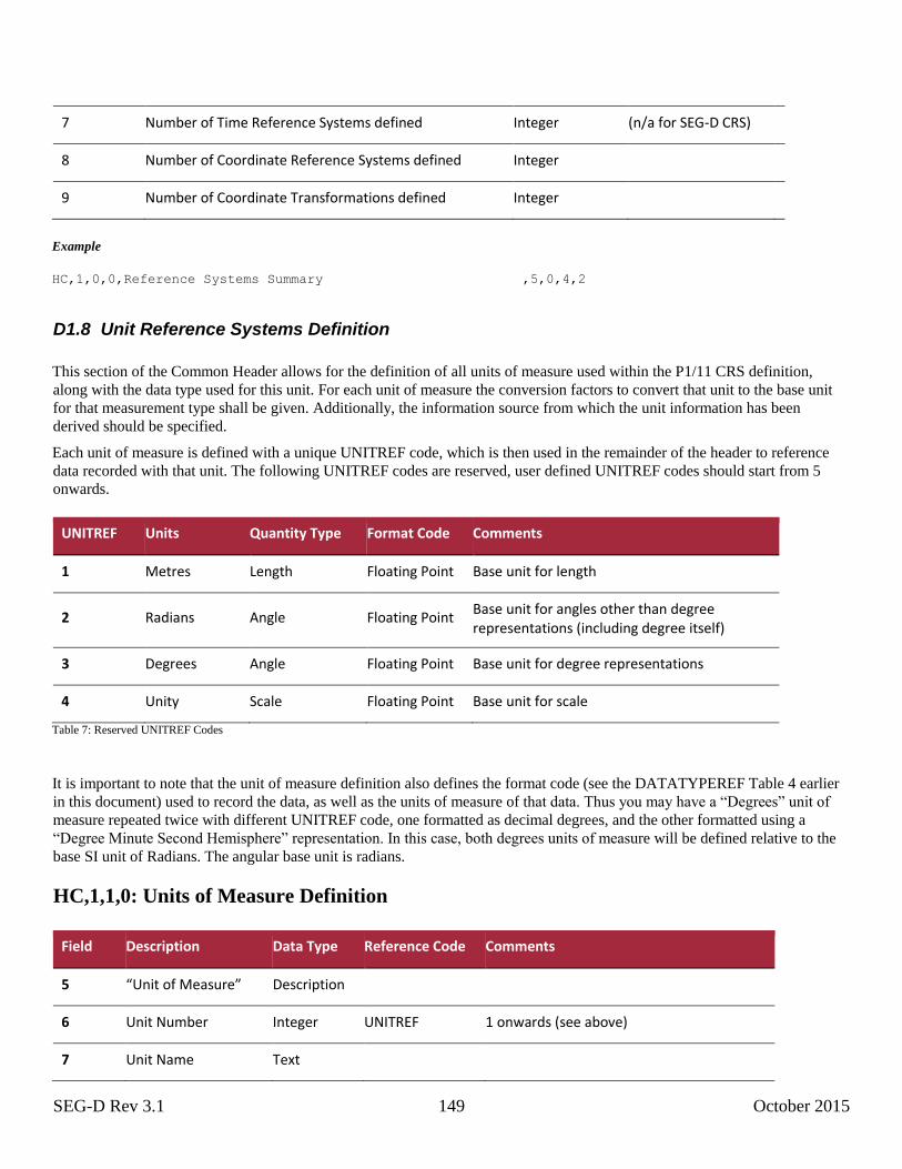
SEG-D Rev 3.1 149 October 2015
7 Number of Time Reference Systems defined Integer (n/a for SEG-D CRS)
8 Number of Coordinate Reference Systems defined Integer
9 Number of Coordinate Transformations defined Integer
Example
HC,1,0,0,Reference Systems Summary.........................,5,0,4,2
D1.8 Unit Reference Systems Definition
This section of the Common Header allows for the definition of all units of measure used within the P1/11 CRS definition,
along with the data type used for this unit. For each unit of measure the conversion factors to convert that unit to the base unit
for that measurement type shall be given. Additionally, the information source from which the unit information has been
derived should be specified.
Each unit of measure is defined with a unique UNITREF code, which is then used in the remainder of the header to reference
data recorded with that unit. The following UNITREF codes are reserved, user defined UNITREF codes should start from 5
onwards.
UNITREF Units Quantity Type Format Code Comments
1 Metres Length Floating Point Base unit for length
2 Radians Angle Floating Point Base unit for angles other than degree representations (including degree itself)
3 Degrees Angle Floating Point Base unit for degree representations
4 Unity Scale Floating Point Base unit for scale
Table 7: Reserved UNITREF Codes
It is important to note that the unit of measure definition also defines the format code (see the DATATYPEREF Table 4 earlier
in this document) used to record the data, as well as the units of measure of that data. Thus you may have a “Degrees” unit of
measure repeated twice with different UNITREF code, one formatted as decimal degrees, and the other formatted using a
“Degree Minute Second Hemisphere” representation. In this case, both degrees units of measure will be defined relative to the
base SI unit of Radians. The angular base unit is radians.
HC,1,1,0: Units of Measure Definition
Field Description Data Type Reference Code Comments
5 “Unit of Measure” Description
6 Unit Number Integer UNITREF 1 onwards (see above)
7 Unit Name Text
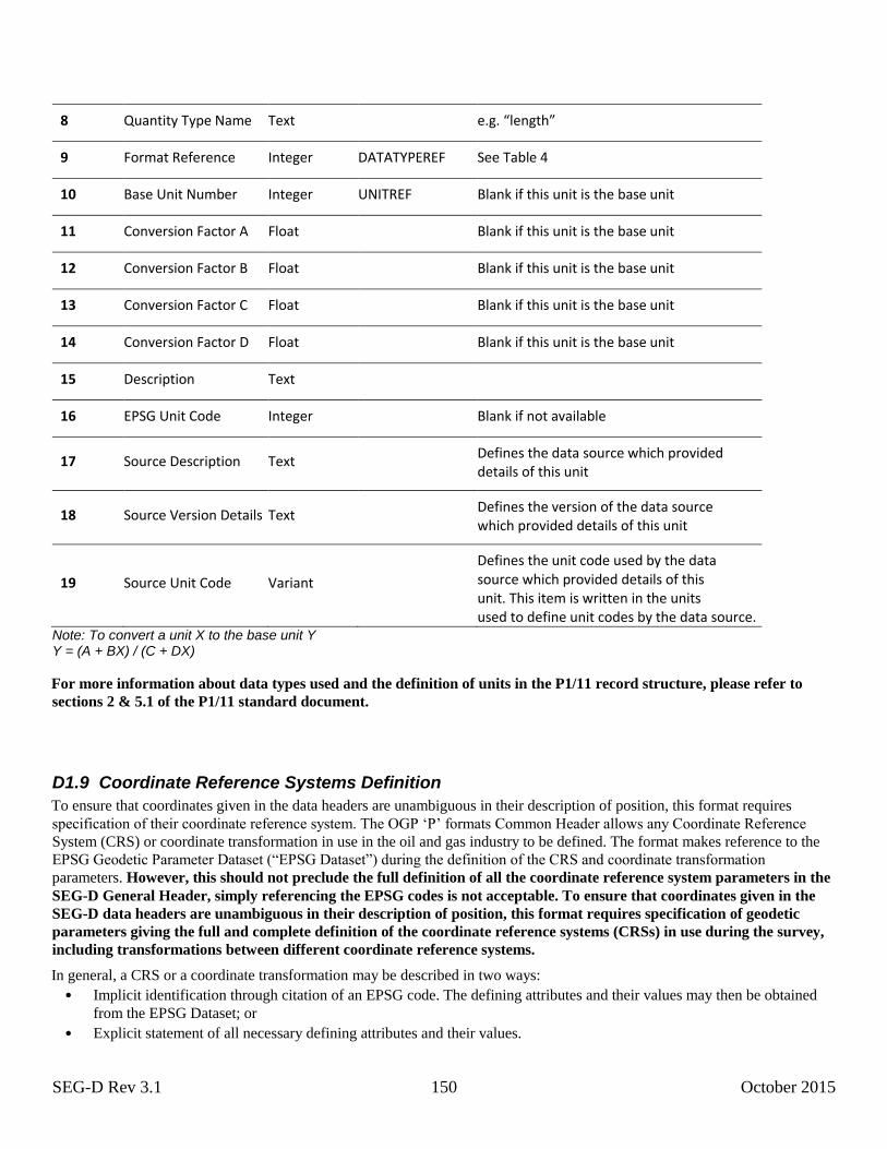
SEG-D Rev 3.1 150 October 2015
8 Quantity Type Name Text e.g. “length”
9 Format Reference Integer DATATYPEREF See Table 4
10 Base Unit Number Integer UNITREF Blank if this unit is the base unit
11 Conversion Factor A Float Blank if this unit is the base unit
12 Conversion Factor B Float Blank if this unit is the base unit
13 Conversion Factor C Float Blank if this unit is the base unit
14 Conversion Factor D Float Blank if this unit is the base unit
15 Description Text
16 EPSG Unit Code Integer Blank if not available
17 Source Description Text Defines the data source which provided
details of this unit
18 Source Version Details Text Defines the version of the data source
which provided details of this unit
19 Source Unit Code Variant
Defines the unit code used by the data source which provided details of this unit. This item is written in the units used to define unit codes by the data source.
Note: To convert a unit X to the base unit Y Y = (A + BX) / (C + DX)
For more information about data types used and the definition of units in the P1/11 record structure, please refer to
sections 2 & 5.1 of the P1/11 standard document.
D1.9 Coordinate Reference Systems Definition
To ensure that coordinates given in the data headers are unambiguous in their description of position, this format requires
specification of their coordinate reference system. The OGP ‘P’ formats Common Header allows any Coordinate Reference
System (CRS) or coordinate transformation in use in the oil and gas industry to be defined. The format makes reference to the
EPSG Geodetic Parameter Dataset (“EPSG Dataset”) during the definition of the CRS and coordinate transformation
parameters. However, this should not preclude the full definition of all the coordinate reference system parameters in the
SEG-D General Header, simply referencing the EPSG codes is not acceptable. To ensure that coordinates given in the
SEG-D data headers are unambiguous in their description of position, this format requires specification of geodetic
parameters giving the full and complete definition of the coordinate reference systems (CRSs) in use during the survey,
including transformations between different coordinate reference systems.
In general, a CRS or a coordinate transformation may be described in two ways:
• Implicit identification through citation of an EPSG code. The defining attributes and their values may then be obtained
from the EPSG Dataset; or
• Explicit statement of all necessary defining attributes and their values.

SEG-D Rev 3.1 151 October 2015
In the P1/11 CRS format implicit identification alone is not acceptable. It is required by this format that the SEG-D General
Header contains the full defining parameters for all CRSs and any transformations used (“explicit definition”), and also includes
implicit identification whenever the CRS or coordinate transformation data is in the EPSG Dataset.
To ensure that the format handles cases where the EPSG Dataset cannot be referenced in the definition of the geodetic
parameters, the format defines internal codes for CRS Number (CRSREF) and Coordinate Transformation Number
(COTRANSREF). If the EPSG Dataset is referenced then these internal codes are cross referenced to the EPSG code in the
header. The internal codes are always the values used within the data headers.
In addition to the CRSs to which the coordinates in the file are referenced, the full set of survey geodetic information of earlier
CRSs should be described in the Common Header to ensure that any transformation back to the earlier CRS or a common
coordinate reference system (such as WGS 84) uses the correct parameters.
Latitude and longitude in the SEG-D data headers shall be given in decimal degrees, but when parameters in transformation and
conversion definitions they should be written in the same unit and to the same resolution as supplied by the information source.
Thus EPSG unit code 9122 “degree (supplier to define representation)” should be regarded as decimal degrees within the ‘P’
formats.
The format follows the structure of the EPSG Geodetic Parameter Dataset and requires the use of the following parameter codes
from that dataset.
• Coordinate Operation Method Codes for Map Projections and Transformations.
• Coordinate Operation Parameter Codes for Map Projections and Transformations.
• Coordinate Axis Codes
Any additional codes are provided for cross reference and need only be included if the geodetic parameters are directly
extracted from an EPSG Dataset.
When writing explicit defining attributes and their values, if the application is referencing values from an EPSG-compliant
database, the parameter names, values and units must be exactly as given in that database.
In the EPSG Dataset, most coordinate transformations utilise the 2 dimensional variant of a coordinate reference system,
whereas a GNSS (Global Navigation Satellite System) will provide positions in the 3 dimensional variant of the coordinate
reference system. Thus, to ensure the EPSG structure is followed, it will be necessary to include both these coordinate reference
systems and specify the correct 3D to 2D conversion. The table below defines the coordinate fields for each CRS type:
CRS Type Coordinate Field 1 Coordinate Field 2 Coordinate Field 3
Projected1 Easting or northing2 Northing or easting2 (not used, leave blank)
Geographic 2D Latitude Longitude (not used, leave blank)
Geographic 3D Latitude Longitude Ellipsoidal height
Geocentric Geocentric X Geocentric Y Geocentric Z
Vertical (not used, leave blank) (not used, leave blank) Gravity-related height or depth3
Engineering 1D4 Distance along X axis (not used, leave blank) (not used, leave blank)
Engineering 2D4,5 Distance along X axis Distance along Y axis (not used, leave blank)
Engineering 3D4 Distance along X axis Distance along Y axis Distance along Z axis
Compound6 According to horizontal CRS
According to horizontal CRS
According to vertical CRS
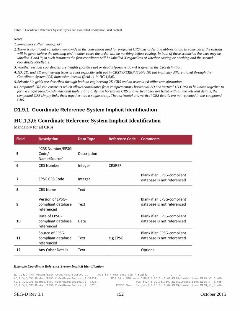
SEG-D Rev 3.1 152 October 2015
Table 9: Coordinate Reference System Types and associated Coordinate Field content
Notes:
1. Sometimes called “map grid”.
2. There is significant variation worldwide in the convention used for projected CRS axis order and abbreviation. In some cases the easting
will be given before the northing and in other cases the order will be northing before easting. In both of these scenarios the axes may be
labelled X and Y; in such instances the first coordinate will be labelled X regardless of whether easting or northing and the second
coordinate labelled Y.
3. Whether vertical coordinates are heights (positive up) or depths (positive down) is given in the CRS definition.
4. 1D, 2D, and 3D engineering types are not explicitly split out in CRSTYPEREF (Table 10) but implicitly differentiated through the
Coordinate System (CS) dimension instead (field 11 in HC,1,6,0).
5. Seismic bin grids are described through both an engineering 2D CRS and an associated affine transformation.
6. Compound CRS is a construct which allows coordinates from complementary horizontal 2D and vertical 1D CRSs to be linked together to
form a single pseudo-3-dimensional tuple. For clarity, the horizontal CRS and vertical CRS are listed with all the relevant details, the
compound CRS simply links them together into a single entity. The horizontal and vertical CRS details are not repeated in the compound
CRS.
D1.9.1 Coordinate Reference System Implicit Identification
HC,1,3,0: Coordinate Reference System Implicit Identification Mandatory for all CRSs
Field Description Data Type Reference Code Comments
5 “CRS Number/EPSG Code/ Name/Source”
Description
6 CRS Number Integer CRSREF
7 EPSG CRS Code Integer Blank if an EPSG-compliant
database is not referenced
8 CRS Name Text
9 Version of EPSG-compliant database referenced
Text Blank if an EPSG-compliant
database is not referenced
10 Date of EPSG-compliant database referenced
Date Blank if an EPSG-compliant
database is not referenced
11 Source of EPSG-compliant database referenced
Text e.g EPSG Blank if an EPSG-compliant database is not referenced
12 Any Other Details Text Optional
Example Coordinate Reference System Implicit Identification
HC,1,3,0,CRS Number/EPSG Code/Name/Source…,1, ,WGS 84 / UTM zone 31N / EGM96, , , , HC,1,3,0,CRS Number/EPSG Code/Name/Source…,2,32631, WGS 84 / UTM zone 31N,7.6,2010:11:02,EPSG,Loaded from EPSG_v7_6.mdb HC,1,3,0,CRS Number/EPSG Code/Name/Source…,3, 4326, WGS 84,7.6,2010:11:02,EPSG,Loaded from EPSG_v7_6.mdb HC,1,3,0,CRS Number/EPSG Code/Name/Source…,4, 5773, EGM96 Geoid Height,7.6,2010:11:02,EPSG,Loaded from EPSG_v7_6.mdb
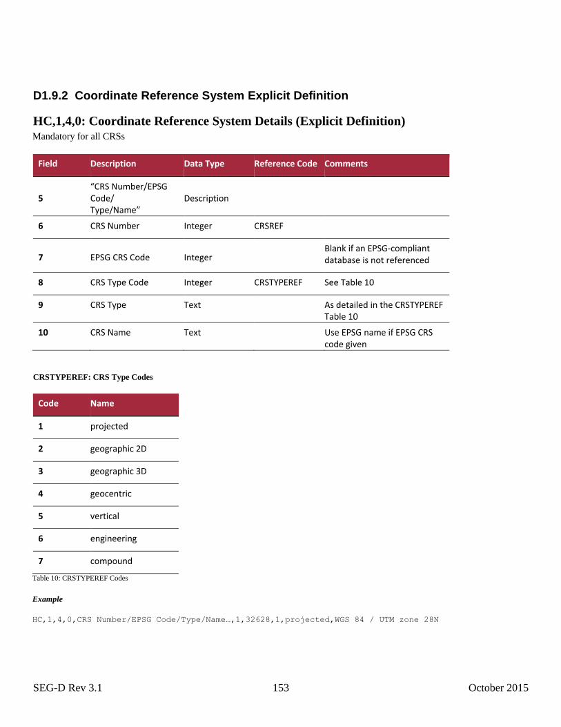
SEG-D Rev 3.1 153 October 2015
D1.9.2 Coordinate Reference System Explicit Definition
HC,1,4,0: Coordinate Reference System Details (Explicit Definition) Mandatory for all CRSs
Field Description Data Type Reference Code Comments
5 “CRS Number/EPSG Code/ Type/Name”
Description
6 CRS Number Integer CRSREF
7 EPSG CRS Code Integer Blank if an EPSG-compliant
database is not referenced
8 CRS Type Code Integer CRSTYPEREF See Table 10
9 CRS Type Text As detailed in the CRSTYPEREF Table 10
10 CRS Name Text Use EPSG name if EPSG CRS code given
CRSTYPEREF: CRS Type Codes
Code Name
1 projected
2 geographic 2D
3 geographic 3D
4 geocentric
5 vertical
6 engineering
7 compound
Table 10: CRSTYPEREF Codes
Example
HC,1,4,0,CRS Number/EPSG Code/Type/Name…,1,32628,1,projected,WGS 84 / UTM zone 28N
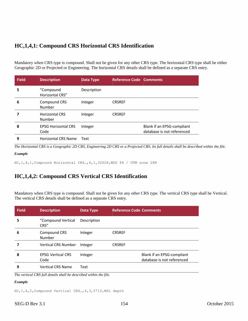
SEG-D Rev 3.1 154 October 2015
HC,1,4,1: Compound CRS Horizontal CRS Identification
Mandatory when CRS type is compound. Shall not be given for any other CRS type. The horizontal CRS type shall be either
Geographic 2D or Projected or Engineering. The horizontal CRS details shall be defined as a separate CRS entry.
Field Description Data Type Reference Code Comments
5 “Compound Horizontal CRS”
Description
6 Compound CRS Number
Integer CRSREF
7 Horizontal CRS Number
Integer CRSREF
8 EPSG Horizontal CRS Code
Integer Blank if an EPSG-compliant database is not referenced
9 Horizontal CRS Name Text
The Horizontal CRS is a Geographic 2D CRS, Engineering 2D CRS or a Projected CRS. Its full details shall be described within the file.
Example
HC,1,4,1,Compound Horizontal CRS…,4,1,32628,WGS 84 / UTM zone 28N
HC,1,4,2: Compound CRS Vertical CRS Identification
Mandatory when CRS type is compound. Shall not be given for any other CRS type. The vertical CRS type shall be Vertical.
The vertical CRS details shall be defined as a separate CRS entry.
Field Description Data Type Reference Code Comments
5 “Compound Vertical CRS”
Description
6 Compound CRS Number
Integer CRSREF
7 Vertical CRS Number Integer CRSREF
8 EPSG Vertical CRS
Code Integer Blank if an EPSG-compliant
database is not referenced
9 Vertical CRS Name Text
The vertical CRS full details shall be described within the file.
Example
HC,1,4,2,Compound Vertical CRS…,4,3,5715,MSL depth
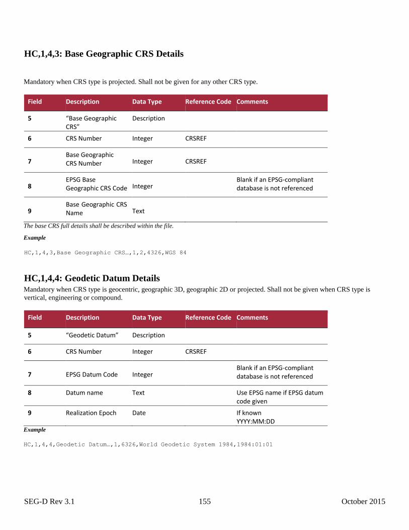
SEG-D Rev 3.1 155 October 2015
HC,1,4,3: Base Geographic CRS Details
Mandatory when CRS type is projected. Shall not be given for any other CRS type.
Field Description Data Type Reference Code Comments
5 “Base Geographic CRS”
Description
6 CRS Number Integer CRSREF
7 Base Geographic CRS Number Integer CRSREF
8 EPSG Base Geographic CRS Code Integer
Blank if an EPSG-compliant database is not referenced
9 Base Geographic CRS
Name Text
The base CRS full details shall be described within the file.
Example
HC,1,4,3,Base Geographic CRS…,1,2,4326,WGS 84
HC,1,4,4: Geodetic Datum Details Mandatory when CRS type is geocentric, geographic 3D, geographic 2D or projected. Shall not be given when CRS type is
vertical, engineering or compound.
Field Description Data Type Reference Code Comments
5 “Geodetic Datum” Description
6 CRS Number Integer CRSREF
7 EPSG Datum Code Integer Blank if an EPSG-compliant
database is not referenced
8 Datum name Text Use EPSG name if EPSG datum code given
9 Realization Epoch Date If known YYYY:MM:DD
Example
HC,1,4,4,Geodetic Datum…,1,6326,World Geodetic System 1984,1984:01:01
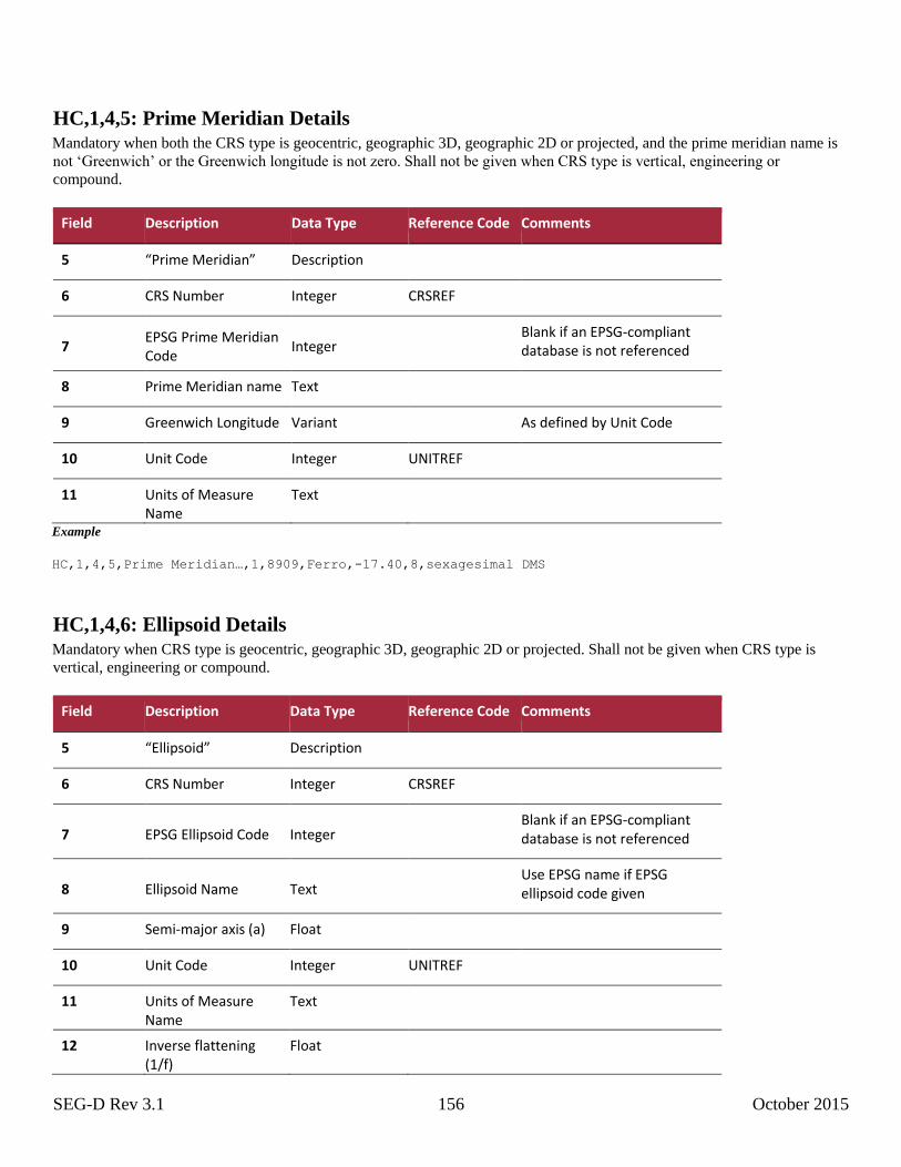
SEG-D Rev 3.1 156 October 2015
HC,1,4,5: Prime Meridian Details Mandatory when both the CRS type is geocentric, geographic 3D, geographic 2D or projected, and the prime meridian name is
not ‘Greenwich’ or the Greenwich longitude is not zero. Shall not be given when CRS type is vertical, engineering or
compound.
Field Description Data Type Reference Code Comments
5 “Prime Meridian” Description
6 CRS Number Integer CRSREF
7 EPSG Prime Meridian Code
Integer Blank if an EPSG-compliant
database is not referenced
8 Prime Meridian name Text
9 Greenwich Longitude Variant As defined by Unit Code
10 Unit Code Integer UNITREF
11 Units of Measure Name
Text
Example
HC,1,4,5,Prime Meridian…,1,8909,Ferro,-17.40,8,sexagesimal DMS
HC,1,4,6: Ellipsoid Details Mandatory when CRS type is geocentric, geographic 3D, geographic 2D or projected. Shall not be given when CRS type is
vertical, engineering or compound.
Field Description Data Type Reference Code Comments
5 “Ellipsoid” Description
6 CRS Number Integer CRSREF
7 EPSG Ellipsoid Code Integer Blank if an EPSG-compliant
database is not referenced
8 Ellipsoid Name Text Use EPSG name if EPSG
ellipsoid code given
9 Semi-major axis (a) Float
10 Unit Code Integer UNITREF
11 Units of Measure Name
Text
12 Inverse flattening (1/f)
Float
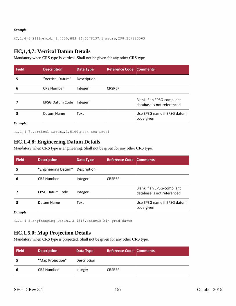
SEG-D Rev 3.1 157 October 2015
Example
HC,1,4,6,Ellipsoid…,1,7030,WGS 84,6378137,1,metre,298.257223563
HC,1,4,7: Vertical Datum Details Mandatory when CRS type is vertical. Shall not be given for any other CRS type.
Field Description Data Type Reference Code Comments
5 “Vertical Datum” Description
6 CRS Number Integer CRSREF
7 EPSG Datum Code Integer Blank if an EPSG-compliant
database is not referenced
8 Datum Name Text Use EPSG name if EPSG datum code given
Example
HC,1,4,7,Vertical Datum…,3,5100,Mean Sea Level
HC,1,4,8: Engineering Datum Details Mandatory when CRS type is engineering. Shall not be given for any other CRS type.
Field Description Data Type Reference Code Comments
5 “Engineering Datum” Description
6 CRS Number Integer CRSREF
7 EPSG Datum Code Integer Blank if an EPSG-compliant
database is not referenced
8 Datum Name Text Use EPSG name if EPSG datum code given
Example
HC,1,4,8,Engineering Datum…,3,9315,Seismic bin grid datum
HC,1,5,0: Map Projection Details Mandatory when CRS type is projected. Shall not be given for any other CRS type.
Field Description Data Type Reference Code Comments
5 “Map Projection” Description
6 CRS Number Integer CRSREF
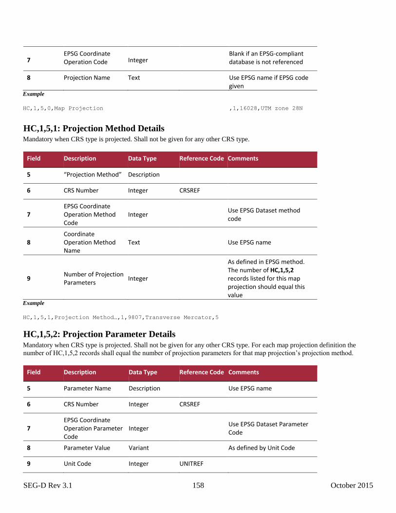
SEG-D Rev 3.1 158 October 2015
7 EPSG Coordinate Operation Code Integer
Blank if an EPSG-compliant database is not referenced
8 Projection Name Text Use EPSG name if EPSG code given
Example
HC,1,5,0,Map Projection ,1,16028,UTM zone 28N
HC,1,5,1: Projection Method Details Mandatory when CRS type is projected. Shall not be given for any other CRS type.
Field Description Data Type Reference Code Comments
5 “Projection Method” Description
6 CRS Number Integer CRSREF
7 EPSG Coordinate Operation Method Code
Integer
Use EPSG Dataset method code
8 Coordinate Operation Method Name
Text
Use EPSG name
9 Number of Projection Parameters
Integer
As defined in EPSG method. The number of HC,1,5,2 records listed for this map projection should equal this value
Example
HC,1,5,1,Projection Method…,1,9807,Transverse Mercator,5
HC,1,5,2: Projection Parameter Details
Mandatory when CRS type is projected. Shall not be given for any other CRS type. For each map projection definition the
number of HC,1,5,2 records shall equal the number of projection parameters for that map projection’s projection method.
Field Description Data Type Reference Code Comments
5 Parameter Name Description Use EPSG name
6 CRS Number Integer CRSREF
7 EPSG Coordinate Operation Parameter Code
Integer
Use EPSG Dataset Parameter Code
8 Parameter Value Variant As defined by Unit Code
9 Unit Code Integer UNITREF
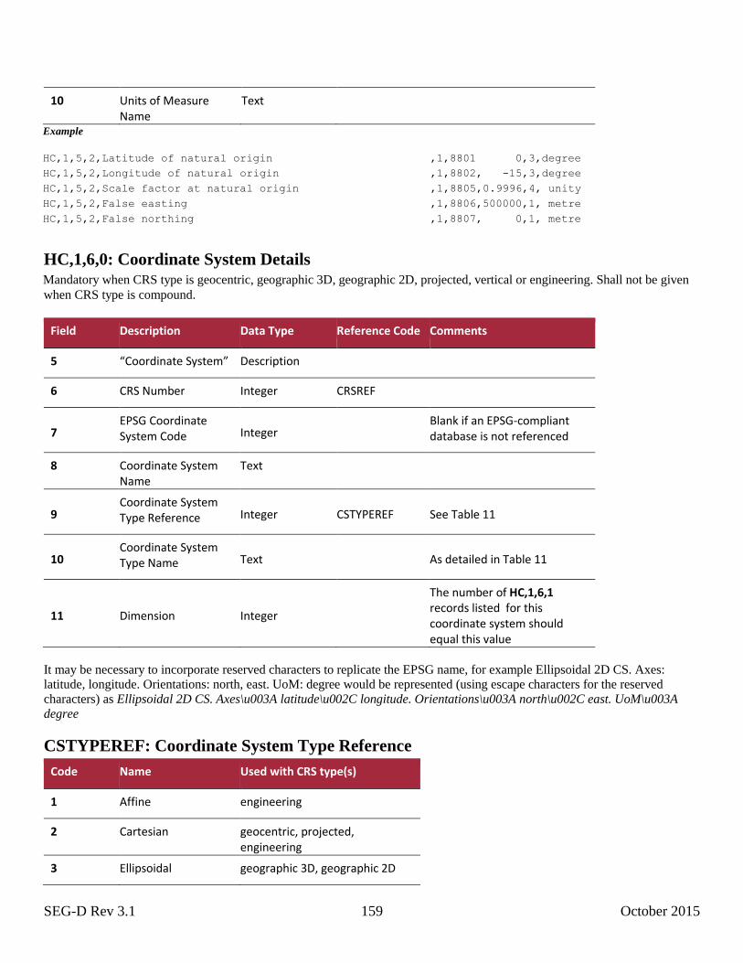
SEG-D Rev 3.1 159 October 2015
10 Units of Measure Name
Text
Example
HC,1,5,2,Latitude of natural origin ,1,8801 0,3,degree HC,1,5,2,Longitude of natural origin ,1,8802, -15,3,degree HC,1,5,2,Scale factor at natural origin ,1,8805,0.9996,4, unity HC,1,5,2,False easting ,1,8806,500000,1, metre HC,1,5,2,False northing ,1,8807, 0,1, metre
HC,1,6,0: Coordinate System Details Mandatory when CRS type is geocentric, geographic 3D, geographic 2D, projected, vertical or engineering. Shall not be given
when CRS type is compound.
Field Description Data Type Reference Code Comments
5 “Coordinate System” Description
6 CRS Number Integer CRSREF
7 EPSG Coordinate System Code Integer
Blank if an EPSG-compliant database is not referenced
8 Coordinate System Name
Text
9 Coordinate System Type Reference Integer CSTYPEREF See Table 11
10 Coordinate System Type Name Text
As detailed in Table 11
11 Dimension Integer
The number of HC,1,6,1 records listed for this coordinate system should equal this value
It may be necessary to incorporate reserved characters to replicate the EPSG name, for example Ellipsoidal 2D CS. Axes:
latitude, longitude. Orientations: north, east. UoM: degree would be represented (using escape characters for the reserved
characters) as Ellipsoidal 2D CS. Axes\u003A latitude\u002C longitude. Orientations\u003A north\u002C east. UoM\u003A
degree
CSTYPEREF: Coordinate System Type Reference
Code Name Used with CRS type(s)
1 Affine engineering
2 Cartesian geocentric, projected, engineering
3 Ellipsoidal geographic 3D, geographic 2D
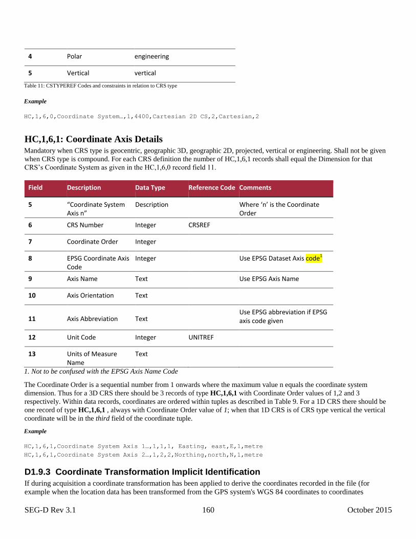
SEG-D Rev 3.1 160 October 2015
4 Polar engineering
5 Vertical vertical
Table 11: CSTYPEREF Codes and constraints in relation to CRS type
Example
HC,1,6,0,Coordinate System…,1,4400,Cartesian 2D CS,2,Cartesian,2
HC,1,6,1: Coordinate Axis Details
Mandatory when CRS type is geocentric, geographic 3D, geographic 2D, projected, vertical or engineering. Shall not be given
when CRS type is compound. For each CRS definition the number of HC,1,6,1 records shall equal the Dimension for that
CRS’s Coordinate System as given in the HC,1,6,0 record field 11.
Field Description Data Type Reference Code Comments
5 “Coordinate System Axis n”
Description Where ‘n’ is the Coordinate Order
6 CRS Number Integer CRSREF
7 Coordinate Order Integer
8 EPSG Coordinate Axis Code
Integer Use EPSG Dataset Axis code1
9 Axis Name Text Use EPSG Axis Name
10 Axis Orientation Text
11 Axis Abbreviation Text Use EPSG abbreviation if EPSG
axis code given
12 Unit Code Integer UNITREF
13 Units of Measure Name
Text
1. Not to be confused with the EPSG Axis Name Code
The Coordinate Order is a sequential number from 1 onwards where the maximum value n equals the coordinate system
dimension. Thus for a 3D CRS there should be 3 records of type HC,1,6,1 with Coordinate Order values of 1,2 and 3
respectively. Within data records, coordinates are ordered within tuples as described in Table 9. For a 1D CRS there should be
one record of type HC,1,6,1 , always with Coordinate Order value of 1; when that 1D CRS is of CRS type vertical the vertical
coordinate will be in the third field of the coordinate tuple.
Example
HC,1,6,1,Coordinate System Axis 1…,1,1,1, Easting, east,E,1,metre HC,1,6,1,Coordinate System Axis 2…,1,2,2,Northing,north,N,1,metre
D1.9.3 Coordinate Transformation Implicit Identification
If during acquisition a coordinate transformation has been applied to derive the coordinates recorded in the file (for
example when the location data has been transformed from the GPS system's WGS 84 coordinates to coordinates
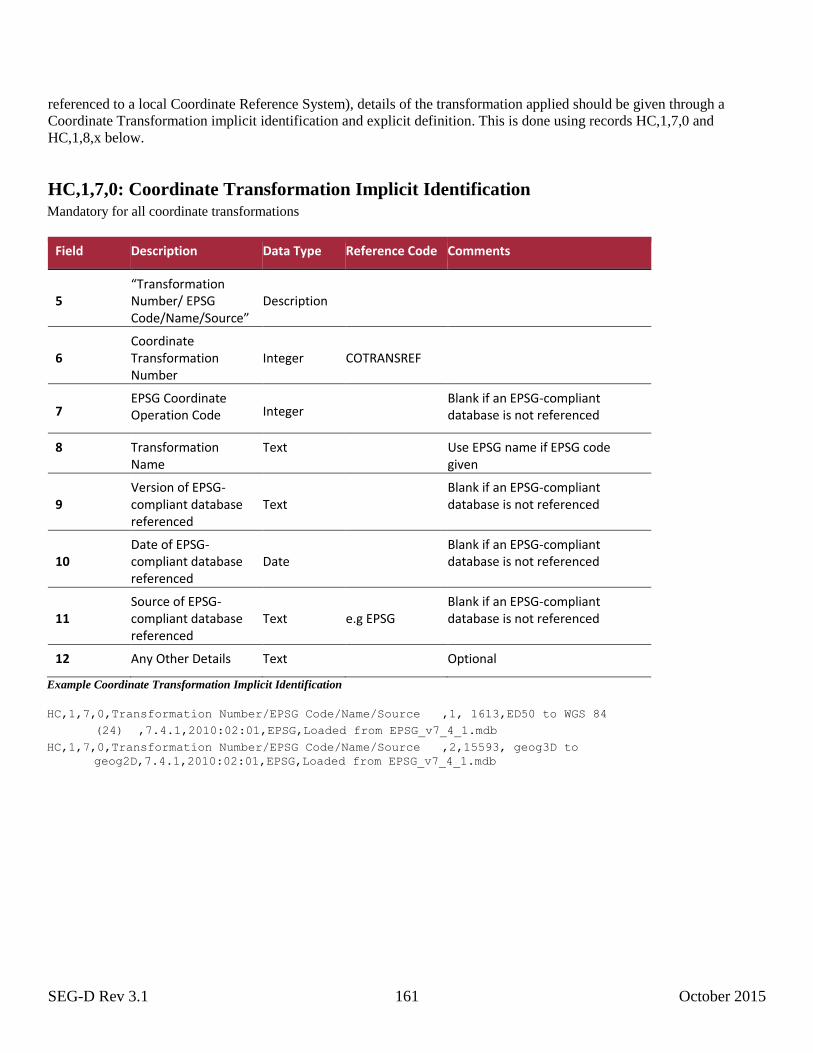
SEG-D Rev 3.1 161 October 2015
referenced to a local Coordinate Reference System), details of the transformation applied should be given through a
Coordinate Transformation implicit identification and explicit definition. This is done using records HC,1,7,0 and
HC,1,8,x below.
HC,1,7,0: Coordinate Transformation Implicit Identification Mandatory for all coordinate transformations
Field Description Data Type Reference Code Comments
5 “Transformation Number/ EPSG Code/Name/Source”
Description
6 Coordinate Transformation Number
Integer COTRANSREF
7 EPSG Coordinate Operation Code Integer
Blank if an EPSG-compliant database is not referenced
8 Transformation Name
Text Use EPSG name if EPSG code given
9 Version of EPSG-compliant database referenced
Text Blank if an EPSG-compliant
database is not referenced
10 Date of EPSG-compliant database referenced
Date Blank if an EPSG-compliant
database is not referenced
11 Source of EPSG-compliant database referenced
Text e.g EPSG Blank if an EPSG-compliant database is not referenced
12 Any Other Details Text Optional
Example Coordinate Transformation Implicit Identification
HC,1,7,0,Transformation Number/EPSG Code/Name/Source ,1, 1613,ED50 to WGS 84 (24) ,7.4.1,2010:02:01,EPSG,Loaded from EPSG_v7_4_1.mdb
HC,1,7,0,Transformation Number/EPSG Code/Name/Source ,2,15593, geog3D to
geog2D,7.4.1,2010:02:01,EPSG,Loaded from EPSG_v7_4_1.mdb
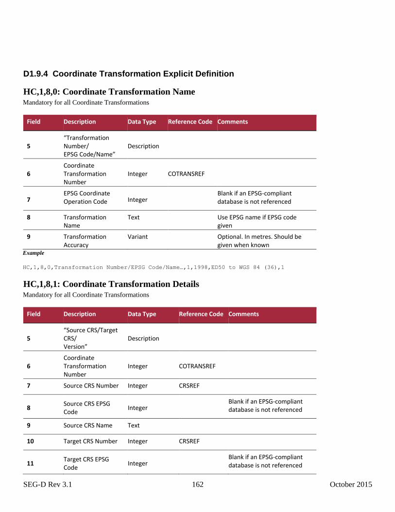
SEG-D Rev 3.1 162 October 2015
D1.9.4 Coordinate Transformation Explicit Definition
HC,1,8,0: Coordinate Transformation Name Mandatory for all Coordinate Transformations
Field Description Data Type Reference Code Comments
5 “Transformation Number/ EPSG Code/Name”
Description
6 Coordinate Transformation Number
Integer COTRANSREF
7 EPSG Coordinate Operation Code Integer
Blank if an EPSG-compliant database is not referenced
8 Transformation Name
Text Use EPSG name if EPSG code given
9 Transformation Accuracy
Variant Optional. In metres. Should be given when known
Example
HC,1,8,0,Transformation Number/EPSG Code/Name…,1,1998,ED50 to WGS 84 (36),1
HC,1,8,1: Coordinate Transformation Details Mandatory for all Coordinate Transformations
Field Description Data Type Reference Code Comments
5 “Source CRS/Target CRS/ Version”
Description
6 Coordinate Transformation Number
Integer COTRANSREF
7 Source CRS Number Integer CRSREF
8 Source CRS EPSG Code
Integer Blank if an EPSG-compliant
database is not referenced
9 Source CRS Name Text
10 Target CRS Number Integer CRSREF
11 Target CRS EPSG Code
Integer Blank if an EPSG-compliant
database is not referenced

SEG-D Rev 3.1 163 October 2015
12 Target CRS Name Text
13 Transformation Version
Text Optional
Example
HC,1,8,1,Source CRS/Target CRS/Version…,1,2,4230,ED50,3,4326,WGS 84,EPSG-Ger Nsea
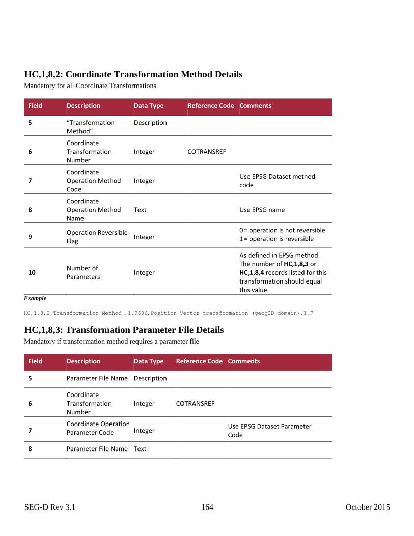
SEG-D Rev 3.1 164 October 2015
HC,1,8,2: Coordinate Transformation Method Details Mandatory for all Coordinate Transformations
Field Description Data Type Reference Code Comments
5 “Transformation Method”
Description
6 Coordinate Transformation Number
Integer COTRANSREF
7 Coordinate Operation Method Code
Integer
Use EPSG Dataset method code
8 Coordinate Operation Method Name
Text
Use EPSG name
9 Operation Reversible Flag
Integer 0 = operation is not reversible
1 = operation is reversible
10 Number of Parameters
Integer
As defined in EPSG method. The number of HC,1,8,3 or HC,1,8,4 records listed for this transformation should equal this value
Example
HC,1,8,2,Transformation Method…,1,9606,Position Vector transformation (geog2D domain),1,7
HC,1,8,3: Transformation Parameter File Details Mandatory if transformation method requires a parameter file
Field Description Data Type Reference Code Comments
5 Parameter File Name Description
6 Coordinate Transformation Number
Integer COTRANSREF
7 Coordinate Operation Parameter Code Integer
Use EPSG Dataset Parameter Code
8 Parameter File Name Text

SEG-D Rev 3.1 165 October 2015
9 Operation Parameter Sign Reversal
Integer
Mandatory if operation method is reversible (HC,1,8,2 record field 9 = 1), not required if operation method is not reversible. 0 = operation parameter sign is not reversed for reverse transformation 1 = operation parameter
sign is reversed for reverse
transformation Example
HC,1,8,3,Latitude difference file ,1,8657,conus.las,1 HC,1,8,3,Longitude difference file ,1,8658,conus.los,1
HC,1,8,4: Transformation Parameter Details Mandatory if transformation method requires a set of parameters
Field Description Data Type Reference Code Comments
5 Parameter Name Description Use EPSG name
6 Coordinate Transformation Number
Integer COTRANSREF
7 Coordinate Operation Parameter Code Integer
Use EPSG Dataset Parameter Code
8 Parameter Value Variant As defined by Unit Code
9 Unit Code Integer UNITREF
10 Units of Measure Name
Text
11 Operation Parameter Sign Reversal
Integer
Mandatory if operation method is reversible (HC,1,8,2 record field 9 = 1), not required if operation method is not reversible. 0 = operation parameter sign is not reversed for reverse transformation 1 = operation parameter
sign is reversed for reverse
transformation Example
HC,1,8,4,X-axis translation…,1,8605,-157.89, 1, metre,1 HC,1,8,4,Y-axis translation…,1,8606, -17.16, 1, metre,1 HC,1,8,4,Z-axis translation…,1,8607, -78.41, 1, metre,1 HC,1,8,4,X-axis rotation… ,1,8608, 2.118, 9, arc-second,1
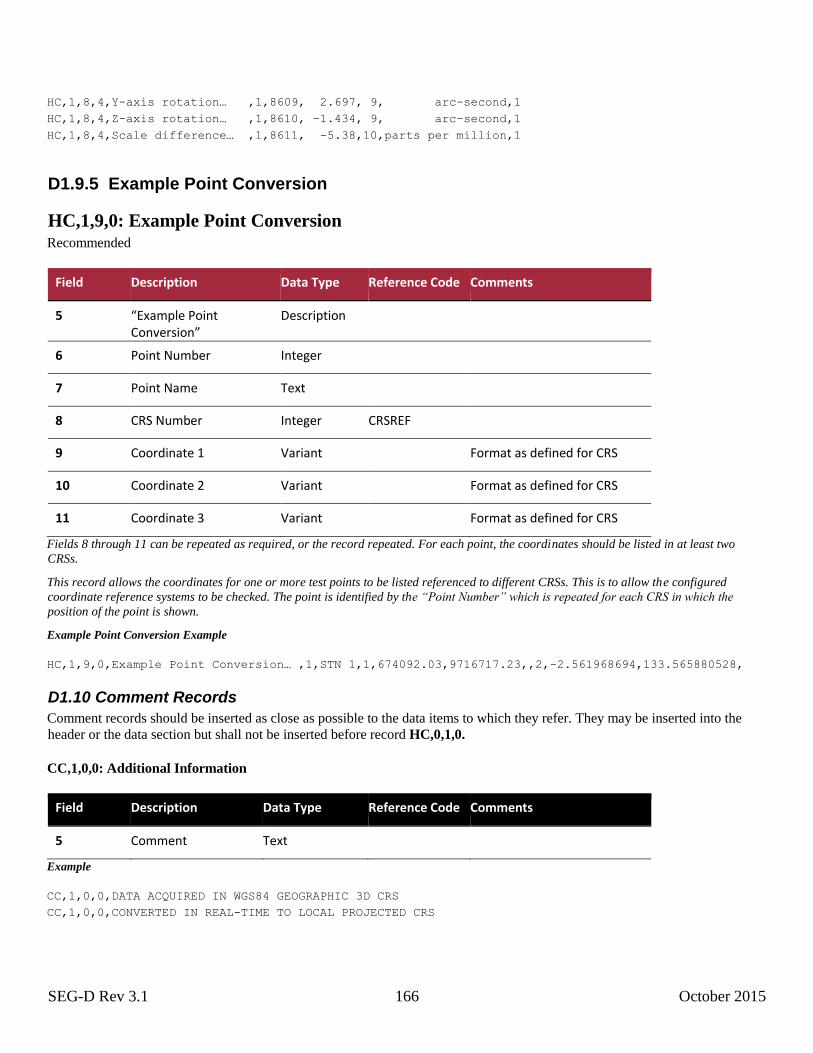
SEG-D Rev 3.1 166 October 2015
HC,1,8,4,Y-axis rotation… ,1,8609, 2.697, 9, arc-second,1 HC,1,8,4,Z-axis rotation… ,1,8610, -1.434, 9, arc-second,1 HC,1,8,4,Scale difference… ,1,8611, -5.38,10,parts per million,1
D1.9.5 Example Point Conversion
HC,1,9,0: Example Point Conversion Recommended
Field Description Data Type Reference Code Comments
5 “Example Point Conversion”
Description
6 Point Number Integer
7 Point Name Text
8 CRS Number Integer CRSREF
9 Coordinate 1 Variant Format as defined for CRS
10 Coordinate 2 Variant Format as defined for CRS
11 Coordinate 3 Variant Format as defined for CRS
Fields 8 through 11 can be repeated as required, or the record repeated. For each point, the coordinates should be listed in at least two
CRSs.
This record allows the coordinates for one or more test points to be listed referenced to different CRSs. This is to allow the configured
coordinate reference systems to be checked. The point is identified by the “Point Number” which is repeated for each CRS in which the
position of the point is shown.
Example Point Conversion Example
HC,1,9,0,Example Point Conversion… ,1,STN 1,1,674092.03,9716717.23,,2,-2.561968694,133.565880528,
D1.10 Comment Records
Comment records should be inserted as close as possible to the data items to which they refer. They may be inserted into the
header or the data section but shall not be inserted before record HC,0,1,0.
CC,1,0,0: Additional Information
Field Description Data Type Reference Code Comments
5 Comment Text
Example
CC,1,0,0,DATA ACQUIRED IN WGS84 GEOGRAPHIC 3D CRS CC,1,0,0,CONVERTED IN REAL-TIME TO LOCAL PROJECTED CRS
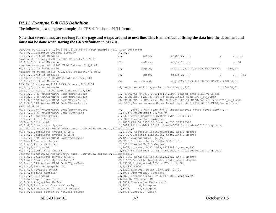
SEG-D Rev 3.1 167 October 2015
D1.11 Example Full CRS Definition
The following is a complete example of a CRS definition in P1/11 format.
Note that several lines are too long for the page and wraps around to next line. This is an artifact of fitting the data into the document and
must not be done when storing the CRS definition in SEG-D. OGP,OGP P1/11,1,1.1,1,2015:03:13,16:55:54,SEGD_example.p111,IOGP Geomatics
HC,1,0,0,Reference Systems Summary ,6,,5,1
HC,1,1,0,Unit of Measure ,1, metre, length,2, , , , , , SI
base unit of length,9001,EPSG Dataset,7.9,9001
HC,1,1,0,Unit of Measure ,2, radian, angle,2, , , , , ,SI
angular measure unit,9101,EPSG Dataset,7.9,9101
HC,1,1,0,Unit of Measure ,3, degree, angle,2,2,0,3.141592653589793, 180,0,
Measure of plane angle,9102,EPSG Dataset,7.9,9102
HC,1,1,0,Unit of Measure ,4, unity, scale,2, , , , , , For
unitless entities,9201,EPSG Dataset,7.9,9201
HC,1,1,0,Unit of Measure ,5, arc-second, angle,2,2,0,3.141592653589793, 648000,0,
1/3600 of a degree,9104,EPSG Dataset,7.9,9104
HC,1,1,0,Unit of Measure ,6,parts per million,scale difference,2,4,0, 1,1000000,0,
Parts per million,9202,EPSG Dataset,7.9,9202
HC,1,3,0,CRS Number/EPSG Code/Name/Source ,1, 4326,WGS 84,8.2,2013:05:14,EPSG,Loaded from EPSG_v8_2.mdb
HC,1,3,0,CRS Number/EPSG Code/Name/Source ,2, 4230,ED50,8.2,2013:05:14,EPSG,Loaded from EPSG_v8_2.mdb
HC,1,3,0,CRS Number/EPSG Code/Name/Source ,3,23030,ED50 / UTM zone 30N,8.2,2013:05:14,EPSG,Loaded from EPSG_v8_2.mdb
HC,1,3,0,CRS Number/EPSG Code/Name/Source ,4, 5831,Instantaneous Water Level depth,8.6,2014:08:10,EPSG,Loaded from
EPSG_v8_6.mdb
HC,1,3,0,CRS Number/EPSG Code/Name/Source ,5, ,ED50 / UTM zone 30N / Instantaneous Water Level depth,,,,
HC,1,4,0,CRS Number/EPSG Code/Type/Name ,1,4326,2,geographic 2D,WGS 84
HC,1,4,4,Geodetic Datum ,1,6326,World Geodetic System 1984,1984:01:01
HC,1,4,5,Prime Meridian ,1,8901,Greenwich,0,3,degree
HC,1,4,6,Ellipsoid ,1,7030,WGS 84,6378137,1,metre,298.257223563
HC,1,6,0,Coordinate System ,1,6422,Ellipsoidal 2D CS. Axes\u003A latitude\u002C longitude.
Orientations\u003A north\u002C east. UoM\u003A degree,3,Ellipsoidal,2
HC,1,6,1,Coordinate System Axis 1 ,1,1,106, Geodetic latitude,north, Lat,3,degree
HC,1,6,1,Coordinate System Axis 2 ,1,2,107,Geodetic longitude, east,Long,3,degree
HC,1,4,0,CRS Number/EPSG Code/Type/Name ,2,4230,2,geographic 2D,ED50
HC,1,4,4,Geodetic Datum ,2,6230,European Datum 1950,1950:01:01
HC,1,4,5,Prime Meridian ,2,8901,Greenwich,0,3,degree
HC,1,4,6,Ellipsoid ,2,7022,International 1924,6378388,1,metre,297
HC,1,6,0,Coordinate System ,2,6422,Ellipsoidal 2D CS. Axes\u003A latitude\u002C longitude.
Orientations\u003A north\u002C east. UoM\u003A degree,3,Ellipsoidal,2
HC,1,6,1,Coordinate System Axis 1 ,2,1,106, Geodetic latitude,north, Lat,3,degree
HC,1,6,1,Coordinate System Axis 2 ,2,2,107,Geodetic longitude, east,Long,3,degree
HC,1,4,0,CRS Number/EPSG Code/Type/Name ,3,23030,1,projected,ED50 / UTM zone 30N
HC,1,4,3,Base Geographic CRS ,3,2,4230,ED50
HC,1,4,4,Geodetic Datum ,3,6230,European Datum 1950,1950:01:01
HC,1,4,5,Prime Meridian ,3,8901,Greenwich,0,3,degree
HC,1,4,6,Ellipsoid ,3,7022,International 1924,6378388,1,metre,297
HC,1,5,0,Map Projection ,3,16030,UTM zone 30N
HC,1,5,1,Projection Method ,3,9807,Transverse Mercator,5
HC,1,5,2,Latitude of natural origin ,3,8801, 0,3,degree
HC,1,5,2,Longitude of natural origin ,3,8802, -3,3,degree
HC,1,5,2,Scale factor at natural origin ,3,8805,0.9996,4, unity
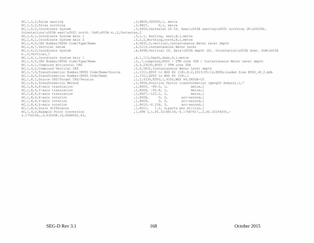
SEG-D Rev 3.1 168 October 2015
HC,1,5,2,False easting ,3,8806,500000,1, metre
HC,1,5,2,False northing ,3,8807, 0,1, metre
HC,1,6,0,Coordinate System ,3,4400,Cartesian 2D CS. Axes\u003A easting\u002C northing (E\u002CN).
Orientations\u003A east\u002C north. UoM\u003A m.,2,Cartesian,2
HC,1,6,1,Coordinate System Axis 1 ,3,1,1, Easting, east,E,1,metre
HC,1,6,1,Coordinate System Axis 2 ,3,2,2,Northing,north,N,1,metre
HC,1,4,0,CRS Number/EPSG Code/Type/Name ,4,5831,5,vertical,Instantaneous Water Level depth
HC,1,4,7,Vertical Datum ,4,5113,Instantaneous Water Level
HC,1,6,0,Coordinate System ,4,6498,Vertical CS. Axis\u003A depth (D). Orientation\u003A down. UoM\u003A
m.,5,Vertical,1
HC,1,6,1,Coordinate System Axis 1 ,4,1,113,Depth,down,D,1,metre
HC,1,4,0,CRS Number/EPSG Code/Type/Name ,5,,7,compound,ED50 / UTM zone 30N / Instantaneous Water Level depth
HC,1,4,1,Compound Horizontal CRS ,5,3,23030,ED50 / UTM zone 30N
HC,1,4,2,Compound Vertical CRS ,5,4,5831,Instantaneous Water Level depth
HC,1,7,0,Transformation Number/EPSG Code/Name/Source ,1,1311,ED50 to WGS 84 (18),8.2,2013:05:14,EPSG,Loaded from EPSG_v8_2.mdb
HC,1,8,0,Transformation Number/EPSG Code/Name ,1,1311,ED50 to WGS 84 (18),1
HC,1,8,1,Source CRS/Target CRS/Version ,1,2,4230,ED50,1,4326,WGS 84,UKOOA-CO
HC,1,8,2,Transformation Method ,1,9606,Position Vector transformation (geog2D domain),1,7
HC,1,8,4,X-axis translation ,1,8605, -89.5, 1, metre,1
HC,1,8,4,Y-axis translation ,1,8606, -93.8, 1, metre,1
HC,1,8,4,Z-axis translation ,1,8607,-123.1, 1, metre,1
HC,1,8,4,X-axis rotation ,1,8608, 0, 5, arc-second,1
HC,1,8,4,Y-axis rotation ,1,8609, 0, 5, arc-second,1
HC,1,8,4,Z-axis rotation ,1,8610,-0.156, 5, arc-second,1
HC,1,8,4,Scale difference ,1,8611, 1.2, 6,parts per million,1
HC,1,9,0,Example Point Conversion ,1,STN 1,1,60.32188139,-4.17687417,,2,60.32249255,-
4.1750199,,3,435098.10,6688062.63,
SEG-D Rev 3.1 169 October 2015
Appendix D2: Coordinate Reference System identification (deprecated)
The Coordinate Reference System Identification format described in this appendix is the old format as used in SEG-D
Rev 3.0. It is still supported for SEG-D Rev 3.1 for backward compatibility reasons, but is deprecated and replaced by
the format described in appendix D1 (P1/11).
Future versions of SEG-D will not support this format, and it is highly recommended that new recording systems
should implement the P1/11 format.
Note: SEG-Y 2.0 will only support the new CRS format described in appendix D1.
Both CRS formats in Appendices D1 and D2 use the same Header Type 5516
The following stanzas are extended versions of the SEG-Y Rev 1 Location Data stanza. The structure for Extended
Textual stanzas is described in section 6.1 of SEG-Y Revision 1 (http://www.seg.org/SEGportalWEBproject/prod/SEG-
Publications/Pub-Technical-Standards/Documents/seg_y_rev1.pdf) and summarized in the following:
The ground rules for stanzas that use this schema are as follows:
Each line consists of a keyword/value pair in the form “keyword = value”.
The keywords and values can contain any printable character except double right or double left parentheses or the
equal sign. However, the use of punctuation characters in keywords is not recommended.
The case of a keyword is not significant.
For readability, spaces within a keyword are allowed but ignored. Thus the keyword “Line Name” refers to the same
keyword as “LINENAME”.
The value associated with a keyword begins with the first non-blank character following the equal sign and extends to
the last non-blank character on the line.
The value field for a keyword may consist of multiple subfields, separated by commas (“,”, EBCDIC 6B16 or ASCII
2C16).
Blank lines are ignored.
If the first non-blank character in a line is the hash sign (“#”, EBCDIC 7B16 or ASCII 2316), the line is treated as a
comment and ignored.
If the last non-blank character on a line is an ampersand (“&”, EBCDIC 5016 or ASCII 1616), the next line is considered
to be a continuation of the current line (i.e. the next line is concatenated with the current line, with the ampersand
removed).
Each line in an Extended Textual File Header ends in carriage return and linefeed (EBCDIC 0D2516 or ASCII 0D0A16)
D2.1 Location Data
Location stanzas provide the definitions for the coordinate reference system to which coordinates given in this SEG-D
format file are referenced. Without this information the coordinates are ambiguous. The stanzas for this coordinate
reference system definition are described in D2.1.1. Examples are given in D2.1.2.
If during acquisition a coordinate transformation has been applied to derive the coordinates defined through the location
stanza (for example when the location data has been transformed from the GPS system's WGS 84 coordinates to
coordinates referenced to a local Coordinate Reference System), details of the transformation applied should additionally
be given through a Coordinate Transformation stanza. The stanzas for this transformation are defined in D2.1.3. Examples
are given in D2.1.4.
SEG-D Rev 3.1 170 October 2015
Some keywords in both the Location Data stanza (D2.1.1 table 1.2) and the Location Data Coordinate Transformation
stanza (D2.1.3 table 1.4) require entry of a parameter from the EPSG Geodetic Parameter Dataset. In some cases, such as
unit of measure, the user has the ability to specify the Unit Name, Unit Code and/or Conversion Factor (to canonical Unit
of Measure). The EPSG dataset is available at www.epsg.org or online at www.epsg-registry.org.
Degree Representation
A sexagesimal degree is defined as “a plane angle represented by a sequence of values in degrees, minutes and seconds.
In the case of latitude or longitude, may also include a character indicating hemisphere.” For example: 50.0795725
degrees is represented as 50º04'46.461"N sexagesimal degrees. To store this in numeric form requires three or four fields.
The EPSG dataset includes a pseudo-unit named sexagesimal DMS which allows the storage of a sexagesimal degree in
one numeric field. The format is:
signed degrees - period - minutes (two digits) - integer seconds (two digits) - fraction of seconds
(any precision). Must include leading zero in minutes and seconds and exclude decimal point for
seconds.
For example 50º04'46.461"S may be represented as −50.0446461 in sexagesimal DMS.
This “unit” is used for documenting (mainly map projection) parameter values where the values must be exactly preserved
and rounding through conversion to decimal degrees cannot be tolerated.
Note that the value given in decimal degrees (e.g. 50.0795725) will differ from its equivalent value given in sexagesimal
DMS (50.0446461) only in the decimal part and that the two representations may be easily confused. Any value given in
sexagesimal DMS must be clearly labeled as such.
Sexagesimal DMS must be used only for geodetic parameter values in the extended textual location data stanzas. For
latitude and longitude coordinates given in General Header records, signed decimal degrees must be used.
D2.1.1 Location Data stanza
The Location Data stanza identifies the Coordinate Reference System (CRS) to which data recording locations, such as
source and group, and derived locations, for example CDP, are referenced. The CRS serves as a reference for both
horizontal positioning, such as easting and northing, and vertical positioning, such as elevations and depths. Without this
identification these coordinates are ambiguous. This information may be given implicitly2 through reference to the EPSG
Geodetic Parameter Dataset (Table 1.1) or explicitly3 (Table 1.2).
Whenever the Coordinate Reference System used is included in the EPSG dataset both the implicit and explicit definition
Textual Location Data stanzas may be provided to ease decoding in environments that lack direct internet access to the
EPSG dataset. If a user extended version of the EPSG dataset is utilized with a code outside of the EPSG reserved range,
then explicit definition is required.
If more than one CRS is used for a given seismic survey, then multiple Location Data Stanzas with unique non-ambiguous
IDs must also be populated.
2 Implicit definition of the Coordinate Reference System (CRS) to which a set of coordinates is referenced requires the user to specify only the
appropriate CRS code and the dataset version number of the EPSG dataset from which that CRS definition was obtained. See Table 1.1 for required
data for an implicit CRS definition. 3 Explicit definition of the Coordinate Reference System (CRS) to which a set of coordinates is referenced requires specifying all of the key attributes
and parameters necessary to define the CRS. See Table 1.2 for required data in an explicit CRS definition.
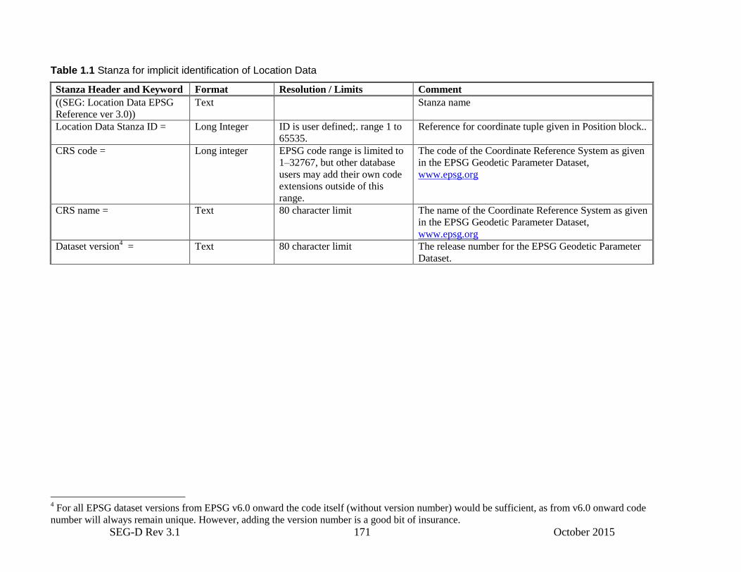
SEG-D Rev 3.1 171 October 2015
Table 1.1 Stanza for implicit identification of Location Data
Stanza Header and Keyword Format Resolution / Limits Comment
((SEG: Location Data EPSG
Reference ver 3.0))
Text Stanza name
Location Data Stanza ID = Long Integer ID is user defined;. range 1 to
65535.
Reference for coordinate tuple given in Position block..
CRS code = Long integer EPSG code range is limited to
1–32767, but other database
users may add their own code
extensions outside of this
range.
The code of the Coordinate Reference System as given
in the EPSG Geodetic Parameter Dataset,
www.epsg.org
CRS name = Text 80 character limit The name of the Coordinate Reference System as given
in the EPSG Geodetic Parameter Dataset,
www.epsg.org
Dataset version4 = Text 80 character limit The release number for the EPSG Geodetic Parameter
Dataset.
4 For all EPSG dataset versions from EPSG v6.0 onward the code itself (without version number) would be sufficient, as from v6.0 onward code
number will always remain unique. However, adding the version number is a good bit of insurance.
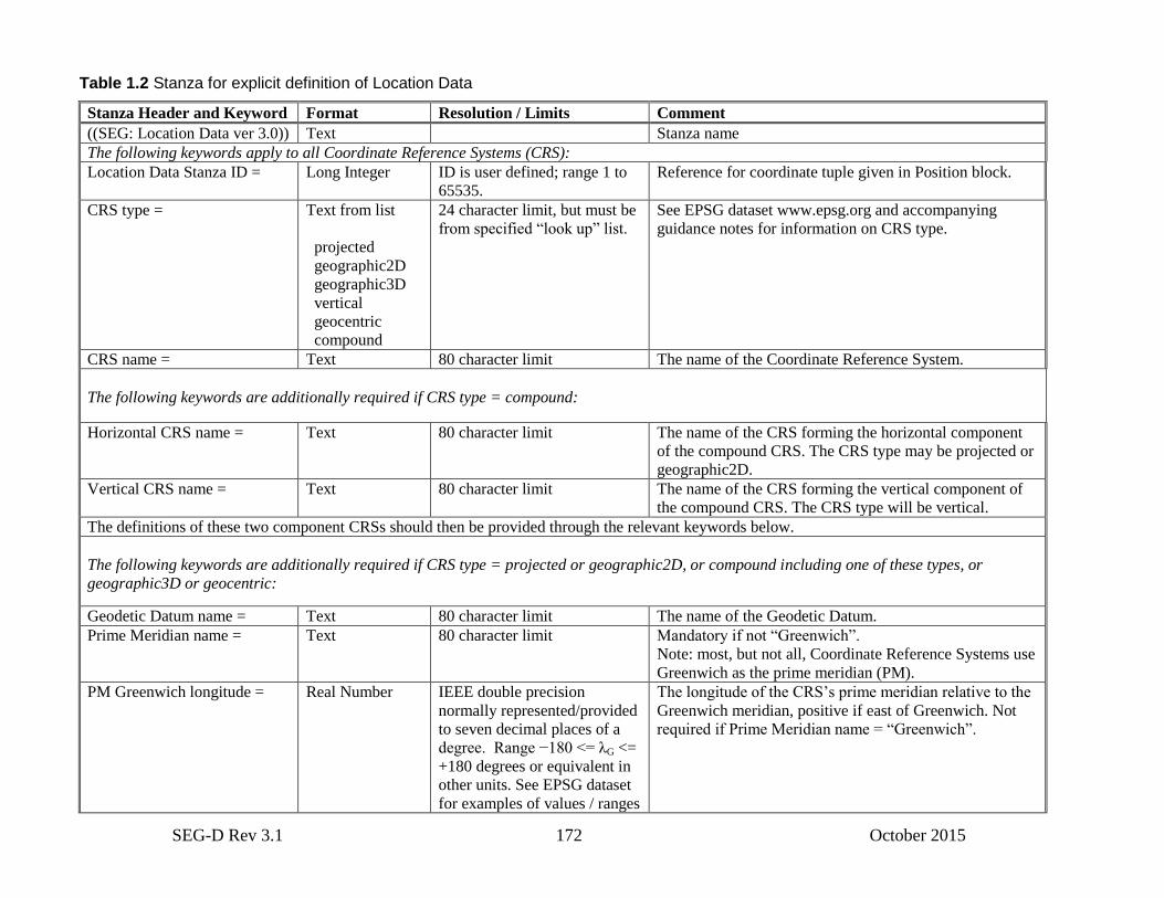
SEG-D Rev 3.1 172 October 2015
Table 1.2 Stanza for explicit definition of Location Data
Stanza Header and Keyword Format Resolution / Limits Comment
((SEG: Location Data ver 3.0)) Text Stanza name
The following keywords apply to all Coordinate Reference Systems (CRS):
Location Data Stanza ID = Long Integer ID is user defined; range 1 to
65535.
Reference for coordinate tuple given in Position block.
CRS type = Text from list
projected
geographic2D
geographic3D
vertical
geocentric
compound
24 character limit, but must be
from specified “look up” list.
See EPSG dataset www.epsg.org and accompanying
guidance notes for information on CRS type.
CRS name = Text 80 character limit The name of the Coordinate Reference System.
The following keywords are additionally required if CRS type = compound:
Horizontal CRS name = Text 80 character limit The name of the CRS forming the horizontal component
of the compound CRS. The CRS type may be projected or
geographic2D.
Vertical CRS name = Text 80 character limit The name of the CRS forming the vertical component of
the compound CRS. The CRS type will be vertical.
The definitions of these two component CRSs should then be provided through the relevant keywords below.
The following keywords are additionally required if CRS type = projected or geographic2D, or compound including one of these types, or
geographic3D or geocentric:
Geodetic Datum name = Text 80 character limit The name of the Geodetic Datum.
Prime Meridian name = Text 80 character limit Mandatory if not “Greenwich”.
Note: most, but not all, Coordinate Reference Systems use
Greenwich as the prime meridian (PM).
PM Greenwich longitude = Real Number IEEE double precision
normally represented/provided
to seven decimal places of a
degree. Range −180 <= λG <=
+180 degrees or equivalent in
other units. See EPSG dataset
for examples of values / ranges
The longitude of the CRS’s prime meridian relative to the
Greenwich meridian, positive if east of Greenwich. Not
required if Prime Meridian name = “Greenwich”.
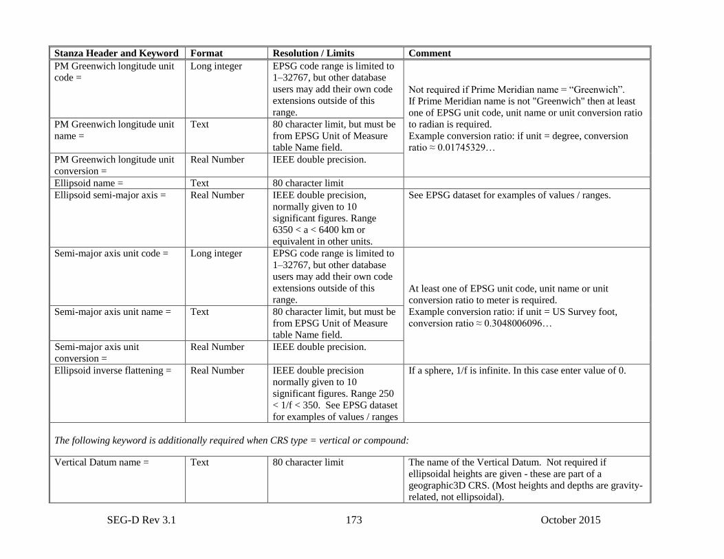
SEG-D Rev 3.1 173 October 2015
Stanza Header and Keyword Format Resolution / Limits Comment
PM Greenwich longitude unit
code =
Long integer EPSG code range is limited to
1–32767, but other database
users may add their own code
extensions outside of this
range.
Not required if Prime Meridian name = “Greenwich”.
If Prime Meridian name is not "Greenwich" then at least
one of EPSG unit code, unit name or unit conversion ratio
to radian is required.
Example conversion ratio: if unit = degree, conversion
ratio ≈ 0.01745329…
PM Greenwich longitude unit
name =
Text 80 character limit, but must be
from EPSG Unit of Measure
table Name field.
PM Greenwich longitude unit
conversion =
Real Number IEEE double precision.
Ellipsoid name = Text 80 character limit
Ellipsoid semi-major axis = Real Number IEEE double precision,
normally given to 10
significant figures. Range
6350 < a < 6400 km or
equivalent in other units.
See EPSG dataset for examples of values / ranges.
Semi-major axis unit code = Long integer EPSG code range is limited to
1–32767, but other database
users may add their own code
extensions outside of this
range. At least one of EPSG unit code, unit name or unit
conversion ratio to meter is required.
Example conversion ratio: if unit = US Survey foot,
conversion ratio ≈ 0.3048006096…
Semi-major axis unit name = Text 80 character limit, but must be
from EPSG Unit of Measure
table Name field.
Semi-major axis unit
conversion =
Real Number IEEE double precision.
Ellipsoid inverse flattening = Real Number IEEE double precision
normally given to 10
significant figures. Range 250
< 1/f < 350. See EPSG dataset
for examples of values / ranges
If a sphere, 1/f is infinite. In this case enter value of 0.
The following keyword is additionally required when CRS type = vertical or compound:
Vertical Datum name = Text 80 character limit The name of the Vertical Datum. Not required if
ellipsoidal heights are given - these are part of a
geographic3D CRS. (Most heights and depths are gravity-
related, not ellipsoidal).
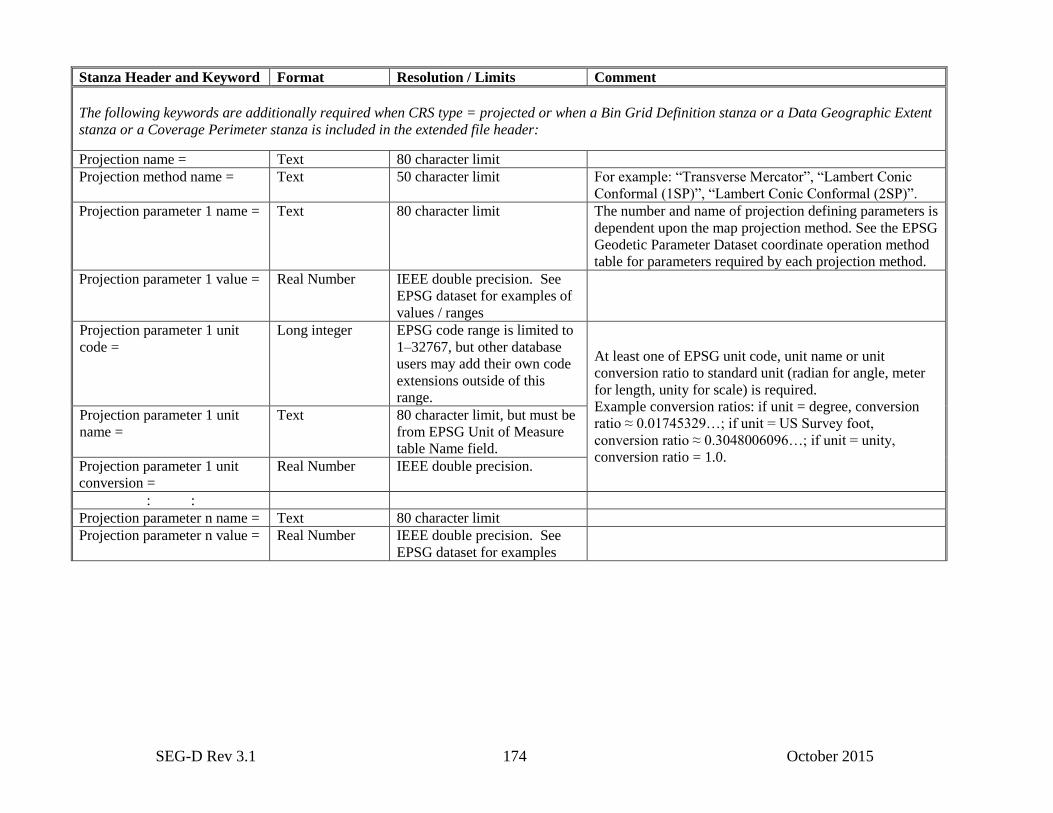
SEG-D Rev 3.1 174 October 2015
Stanza Header and Keyword Format Resolution / Limits Comment
The following keywords are additionally required when CRS type = projected or when a Bin Grid Definition stanza or a Data Geographic Extent
stanza or a Coverage Perimeter stanza is included in the extended file header:
Projection name = Text 80 character limit
Projection method name = Text 50 character limit For example: “Transverse Mercator”, “Lambert Conic
Conformal (1SP)”, “Lambert Conic Conformal (2SP)”.
Projection parameter 1 name = Text 80 character limit The number and name of projection defining parameters is
dependent upon the map projection method. See the EPSG
Geodetic Parameter Dataset coordinate operation method
table for parameters required by each projection method.
Projection parameter 1 value = Real Number IEEE double precision. See
EPSG dataset for examples of
values / ranges
Projection parameter 1 unit
code =
Long integer EPSG code range is limited to
1–32767, but other database
users may add their own code
extensions outside of this
range.
At least one of EPSG unit code, unit name or unit
conversion ratio to standard unit (radian for angle, meter
for length, unity for scale) is required.
Example conversion ratios: if unit = degree, conversion
ratio ≈ 0.01745329…; if unit = US Survey foot,
conversion ratio ≈ 0.3048006096…; if unit = unity,
conversion ratio = 1.0.
Projection parameter 1 unit
name =
Text 80 character limit, but must be
from EPSG Unit of Measure
table Name field.
Projection parameter 1 unit
conversion =
Real Number IEEE double precision.
: :
Projection parameter n name = Text 80 character limit
Projection parameter n value = Real Number IEEE double precision. See
EPSG dataset for examples
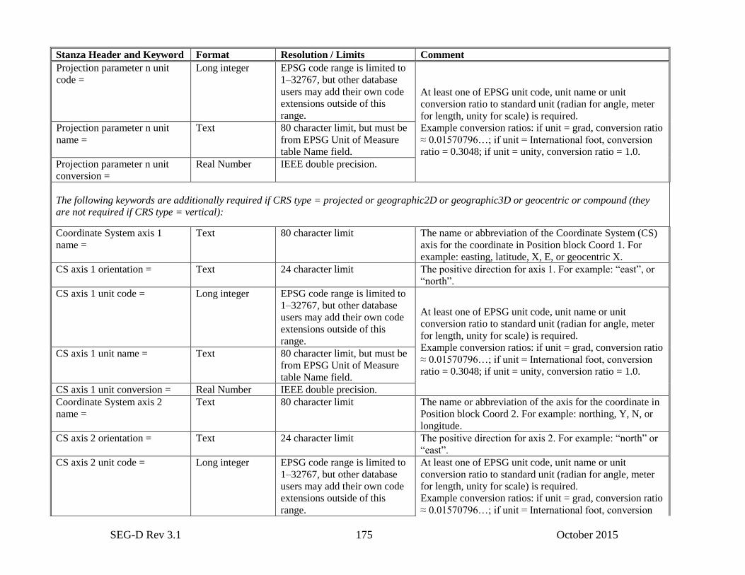
SEG-D Rev 3.1 175 October 2015
Stanza Header and Keyword Format Resolution / Limits Comment
Projection parameter n unit
code =
Long integer EPSG code range is limited to
1–32767, but other database
users may add their own code
extensions outside of this
range.
At least one of EPSG unit code, unit name or unit
conversion ratio to standard unit (radian for angle, meter
for length, unity for scale) is required.
Example conversion ratios: if unit = grad, conversion ratio
≈ 0.01570796…; if unit = International foot, conversion
ratio = 0.3048; if unit = unity, conversion ratio = 1.0.
Projection parameter n unit
name =
Text 80 character limit, but must be
from EPSG Unit of Measure
table Name field.
Projection parameter n unit
conversion =
Real Number IEEE double precision.
The following keywords are additionally required if CRS type = projected or geographic2D or geographic3D or geocentric or compound (they
are not required if CRS type = vertical):
Coordinate System axis 1
name =
Text 80 character limit The name or abbreviation of the Coordinate System (CS)
axis for the coordinate in Position block Coord 1. For
example: easting, latitude, X, E, or geocentric X.
CS axis 1 orientation = Text 24 character limit The positive direction for axis 1. For example: “east”, or
“north”.
CS axis 1 unit code = Long integer EPSG code range is limited to
1–32767, but other database
users may add their own code
extensions outside of this
range.
At least one of EPSG unit code, unit name or unit
conversion ratio to standard unit (radian for angle, meter
for length, unity for scale) is required.
Example conversion ratios: if unit = grad, conversion ratio
≈ 0.01570796…; if unit = International foot, conversion
ratio = 0.3048; if unit = unity, conversion ratio = 1.0.
CS axis 1 unit name = Text 80 character limit, but must be
from EPSG Unit of Measure
table Name field.
CS axis 1 unit conversion = Real Number IEEE double precision.
Coordinate System axis 2
name =
Text 80 character limit The name or abbreviation of the axis for the coordinate in
Position block Coord 2. For example: northing, Y, N, or
longitude.
CS axis 2 orientation = Text 24 character limit The positive direction for axis 2. For example: “north” or
“east”.
CS axis 2 unit code = Long integer EPSG code range is limited to
1–32767, but other database
users may add their own code
extensions outside of this
range.
At least one of EPSG unit code, unit name or unit
conversion ratio to standard unit (radian for angle, meter
for length, unity for scale) is required.
Example conversion ratios: if unit = grad, conversion ratio
≈ 0.01570796…; if unit = International foot, conversion
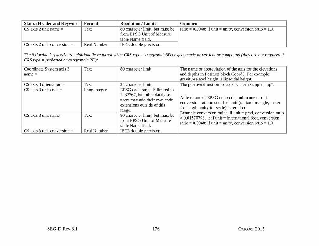
SEG-D Rev 3.1 176 October 2015
Stanza Header and Keyword Format Resolution / Limits Comment
CS axis 2 unit name = Text 80 character limit, but must be
from EPSG Unit of Measure
table Name field.
ratio = 0.3048; if unit = unity, conversion ratio = 1.0.
CS axis 2 unit conversion = Real Number IEEE double precision.
The following keywords are additionally required when CRS type = geographic3D or geocentric or vertical or compound (they are not required if
CRS type = projected or geographic 2D):
Coordinate System axis 3
name =
Text 80 character limit The name or abbreviation of the axis for the elevations
and depths in Position block Coord3. For example:
gravity-related height, ellipsoidal height.
CS axis 3 orientation = Text 24 character limit The positive direction for axis 3. For example: “up”.
CS axis 3 unit code = Long integer EPSG code range is limited to
1–32767, but other database
users may add their own code
extensions outside of this
range.
At least one of EPSG unit code, unit name or unit
conversion ratio to standard unit (radian for angle, meter
for length, unity for scale) is required.
Example conversion ratios: if unit = grad, conversion ratio
≈ 0.01570796…; if unit = International foot, conversion
ratio = 0.3048; if unit = unity, conversion ratio = 1.0.
CS axis 3 unit name = Text 80 character limit, but must be
from EPSG Unit of Measure
table Name field.
CS axis 3 unit conversion = Real Number IEEE double precision.
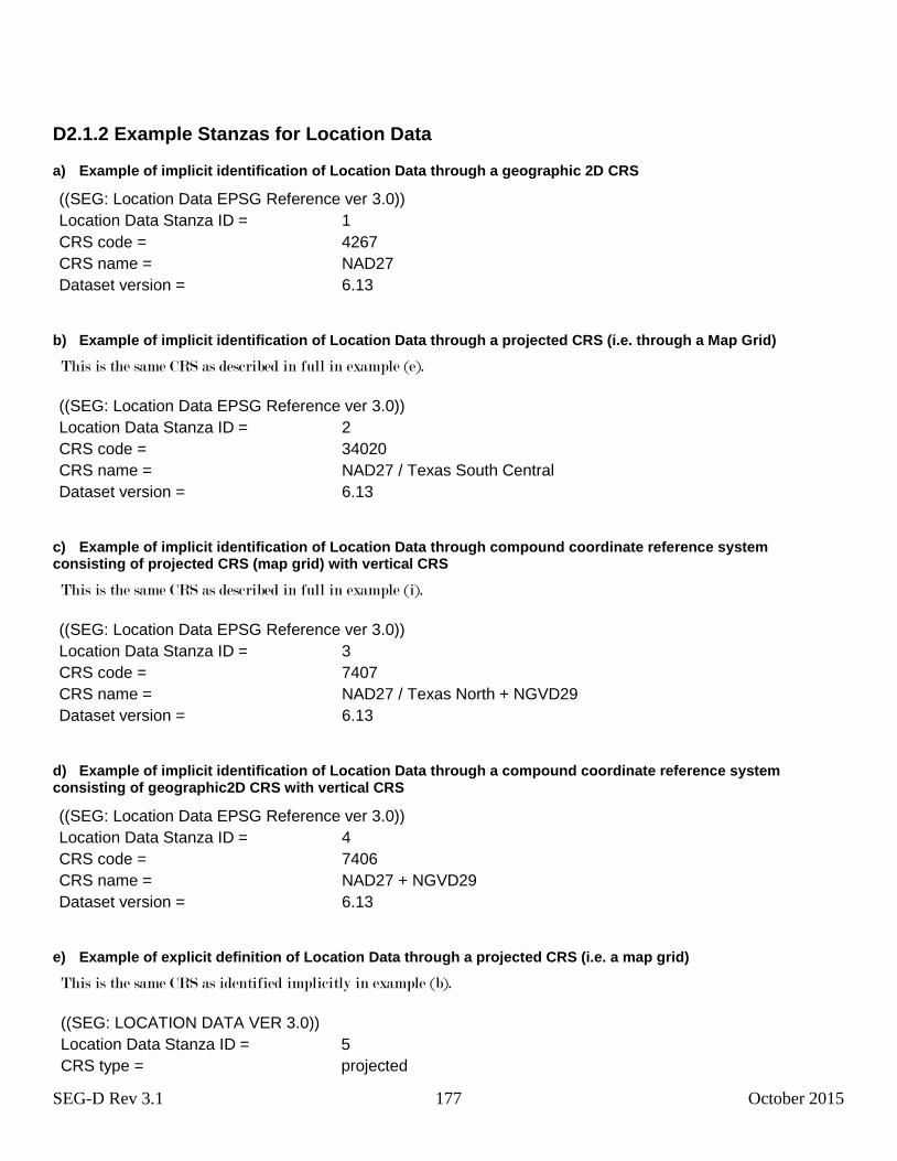
SEG-D Rev 3.1 177 October 2015
D2.1.2 Example Stanzas for Location Data
a) Example of implicit identification of Location Data through a geographic 2D CRS
((SEG: Location Data EPSG Reference ver 3.0))
Location Data Stanza ID = 1
CRS code = 4267
CRS name = NAD27
Dataset version = 6.13
b) Example of implicit identification of Location Data through a projected CRS (i.e. through a Map Grid)
This is the same CRS as described in full in example (e).
((SEG: Location Data EPSG Reference ver 3.0))
Location Data Stanza ID = 2
CRS code = 34020
CRS name = NAD27 / Texas South Central
Dataset version = 6.13
c) Example of implicit identification of Location Data through compound coordinate reference system consisting of projected CRS (map grid) with vertical CRS
This is the same CRS as described in full in example (i).
((SEG: Location Data EPSG Reference ver 3.0))
Location Data Stanza ID = 3
CRS code = 7407
CRS name = NAD27 / Texas North + NGVD29
Dataset version = 6.13
d) Example of implicit identification of Location Data through a compound coordinate reference system consisting of geographic2D CRS with vertical CRS
((SEG: Location Data EPSG Reference ver 3.0))
Location Data Stanza ID = 4
CRS code = 7406
CRS name = NAD27 + NGVD29
Dataset version = 6.13
e) Example of explicit definition of Location Data through a projected CRS (i.e. a map grid)
This is the same CRS as identified implicitly in example (b).
((SEG: LOCATION DATA VER 3.0))
Location Data Stanza ID = 5
CRS type = projected

SEG-D Rev 3.1 178 October 2015
CRS name = NAD27 / Texas South Central
Geodetic Datum name = North American Datum 1927
Ellipsoid name = Clarke 1866
Ellipsoid semi-major axis = 6378206.4
Semi-major axis unit name = meter
Ellipsoid inverse flattening = 294.9786982
Projection name = Texas CS27 South Central zone
Projection method name = Lambert Conic Conformal (2SP)
Projection parameter 1 name = latitude of false origin
Projection parameter 1 value = 27.5
Projection parameter 1 unit name = sexagesimal DMS
Projection parameter 2 name = longitude of false origin
Projection parameter 2 value = −99
Projection parameter 2 unit name = degree
Projection parameter 3 name = latitude of first standard parallel
Projection parameter 3 value = 28.23
Projection parameter 3 unit name = sexagesimal DMS
Projection parameter 4 name = latitude of second standard parallel
Projection parameter 4 value = 30.17
Projection parameter 4 unit name = sexagesimal DMS
Projection parameter 5 name = easting at false origin
Projection parameter 5 value = 2000000.0
Projection parameter 5 unit name = US survey foot
Projection parameter 6 name = northing at false origin
Projection parameter 6 value = 0.0
Projection parameter 6 unit name = US survey foot
Coordinate System axis 1 name = X
CS axis 1 orientation = East
CS axis 1 unit code = 9003
CS axis 1 unit name = US Survey foot
CS axis 1 unit Conversion Ratio = 0.304800609601
Coordinate System axis 2 name = Y
CS axis 2 orientation = North
CS axis 2 unit name = US Survey foot
f) Example of explicit definition of Location Data through a geographic2D CRS
((SEG: LOCATION DATA VER 3.0))
Location Data Stanza ID = 6
CRS type = geographic 2D
CRS name = NTF (Paris)
Geodetic Datum name = Nouvelle Triangulation Francaise (Paris)
# The following three keyword/value pairs are not needed when Prime Meridian = Greenwich.
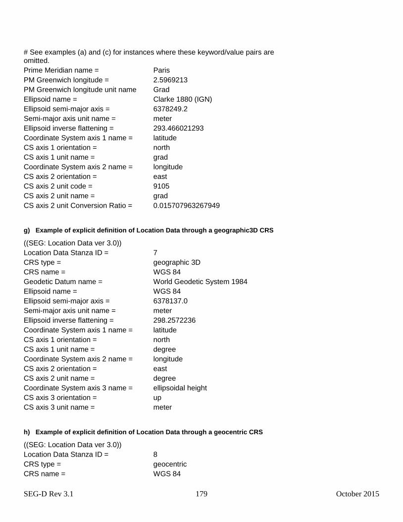
SEG-D Rev 3.1 179 October 2015
# See examples (a) and (c) for instances where these keyword/value pairs are omitted.
Prime Meridian name = Paris
PM Greenwich longitude = 2.5969213
PM Greenwich longitude unit name Grad
Ellipsoid name = Clarke 1880 (IGN)
Ellipsoid semi-major axis = 6378249.2
Semi-major axis unit name = meter
Ellipsoid inverse flattening = 293.466021293
Coordinate System axis 1 name = latitude
CS axis 1 orientation = north
CS axis 1 unit name = grad
Coordinate System axis 2 name = longitude
CS axis 2 orientation = east
CS axis 2 unit code = 9105
CS axis 2 unit name = grad
CS axis 2 unit Conversion Ratio = 0.015707963267949
g) Example of explicit definition of Location Data through a geographic3D CRS
((SEG: Location Data ver 3.0))
Location Data Stanza ID = 7
CRS type = geographic 3D
CRS name = WGS 84
Geodetic Datum name = World Geodetic System 1984
Ellipsoid name = WGS 84
Ellipsoid semi-major axis = 6378137.0
Semi-major axis unit name = meter
Ellipsoid inverse flattening = 298.2572236
Coordinate System axis 1 name = latitude
CS axis 1 orientation = north
CS axis 1 unit name = degree
Coordinate System axis 2 name = longitude
CS axis 2 orientation = east
CS axis 2 unit name = degree
Coordinate System axis 3 name = ellipsoidal height
CS axis 3 orientation = up
CS axis 3 unit name = meter
h) Example of explicit definition of Location Data through a geocentric CRS
((SEG: Location Data ver 3.0))
Location Data Stanza ID = 8
CRS type = geocentric
CRS name = WGS 84
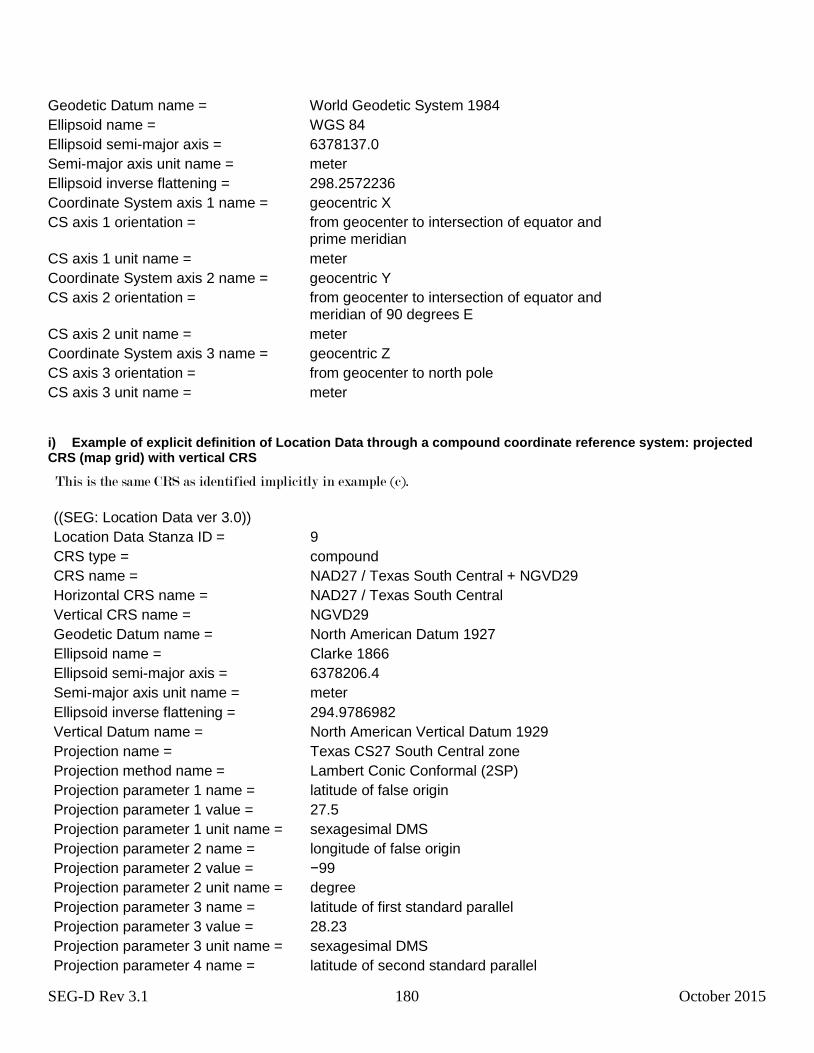
SEG-D Rev 3.1 180 October 2015
Geodetic Datum name = World Geodetic System 1984
Ellipsoid name = WGS 84
Ellipsoid semi-major axis = 6378137.0
Semi-major axis unit name = meter
Ellipsoid inverse flattening = 298.2572236
Coordinate System axis 1 name = geocentric X
CS axis 1 orientation = from geocenter to intersection of equator and prime meridian
CS axis 1 unit name = meter
Coordinate System axis 2 name = geocentric Y
CS axis 2 orientation = from geocenter to intersection of equator and meridian of 90 degrees E
CS axis 2 unit name = meter
Coordinate System axis 3 name = geocentric Z
CS axis 3 orientation = from geocenter to north pole
CS axis 3 unit name = meter
i) Example of explicit definition of Location Data through a compound coordinate reference system: projected CRS (map grid) with vertical CRS
This is the same CRS as identified implicitly in example (c).
((SEG: Location Data ver 3.0))
Location Data Stanza ID = 9
CRS type = compound
CRS name = NAD27 / Texas South Central + NGVD29
Horizontal CRS name = NAD27 / Texas South Central
Vertical CRS name = NGVD29
Geodetic Datum name = North American Datum 1927
Ellipsoid name = Clarke 1866
Ellipsoid semi-major axis = 6378206.4
Semi-major axis unit name = meter
Ellipsoid inverse flattening = 294.9786982
Vertical Datum name = North American Vertical Datum 1929
Projection name = Texas CS27 South Central zone
Projection method name = Lambert Conic Conformal (2SP)
Projection parameter 1 name = latitude of false origin
Projection parameter 1 value = 27.5
Projection parameter 1 unit name = sexagesimal DMS
Projection parameter 2 name = longitude of false origin
Projection parameter 2 value = −99
Projection parameter 2 unit name = degree
Projection parameter 3 name = latitude of first standard parallel
Projection parameter 3 value = 28.23
Projection parameter 3 unit name = sexagesimal DMS
Projection parameter 4 name = latitude of second standard parallel
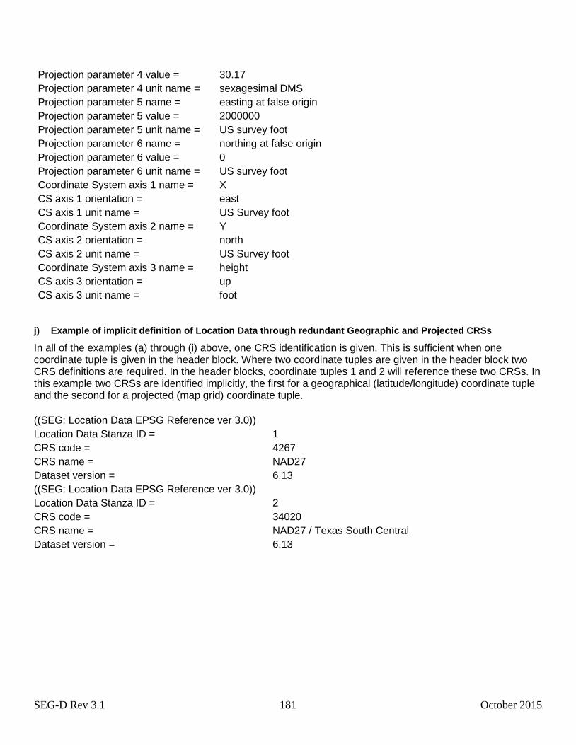
SEG-D Rev 3.1 181 October 2015
Projection parameter 4 value = 30.17
Projection parameter 4 unit name = sexagesimal DMS
Projection parameter 5 name = easting at false origin
Projection parameter 5 value = 2000000
Projection parameter 5 unit name = US survey foot
Projection parameter 6 name = northing at false origin
Projection parameter 6 value = 0
Projection parameter 6 unit name = US survey foot
Coordinate System axis 1 name = X
CS axis 1 orientation = east
CS axis 1 unit name = US Survey foot
Coordinate System axis 2 name = Y
CS axis 2 orientation = north
CS axis 2 unit name = US Survey foot
Coordinate System axis 3 name = height
CS axis 3 orientation = up
CS axis 3 unit name = foot
j) Example of implicit definition of Location Data through redundant Geographic and Projected CRSs
In all of the examples (a) through (i) above, one CRS identification is given. This is sufficient when one coordinate tuple is given in the header block. Where two coordinate tuples are given in the header block two CRS definitions are required. In the header blocks, coordinate tuples 1 and 2 will reference these two CRSs. In this example two CRSs are identified implicitly, the first for a geographical (latitude/longitude) coordinate tuple and the second for a projected (map grid) coordinate tuple.
((SEG: Location Data EPSG Reference ver 3.0))
Location Data Stanza ID = 1
CRS code = 4267
CRS name = NAD27
Dataset version = 6.13
((SEG: Location Data EPSG Reference ver 3.0))
Location Data Stanza ID = 2
CRS code = 34020
CRS name = NAD27 / Texas South Central
Dataset version = 6.13
SEG-D Rev 3.1 182 October 2015
D2.1.3 Location Data Coordinate Transformation stanzas
If during acquisition a coordinate transformation has been applied to derive the coordinates described through a given
Location Data stanza or a given Location Data EPSG Reference stanza (for example when the location data has been
transformed from the GPS system's WGS 84 coordinates to a local Coordinate Reference System), details of the
coordinate transformation which has been applied should be included as a Location Data Coordinate Transformation. A
coordinate transformation may be either "single", i.e. directly from source CRS A to target CRS B, or a "concatenated
operation", that is indirectly from A to B via one or more intermediate CRSs, for example from CRS A to CRS C to CRS
B. In either case the final target CRS, i.e. CRS B, is that defined in the Location Data or Location Data EPSG Reference
stanza.
As with location CRS data the coordinate transformation may be given implicitly5 through reference to the EPSG
Geodetic Parameter Dataset (Table 1.3) or described explicitly6 (Table 1.4).
If more than one CRS is used for a given survey, then an appropriate Location Data Coordinate Transformation Stanza
with a unique ID must be given for each of those CRSs. The Location Data Stanza ID for that unique CRS should be
referenced in the Location Data Coordinate Transformation Stanza (as shown below).
5 Implicit definition of a transformation applied to a given set of coordinates requires the user to specify only the appropriate transformation code and
dataset version number of the EPSG dataset from which that transformation definition was obtained. See Table 1.3 for required data for an implicit
transformation definition. 6 Explicit definition of a transformation applied to a given set of coordinates requires specifying all of the key attributes and parameters necessary to
define that transformation. See Table 1.4 for required data in an explicit transformation definition.
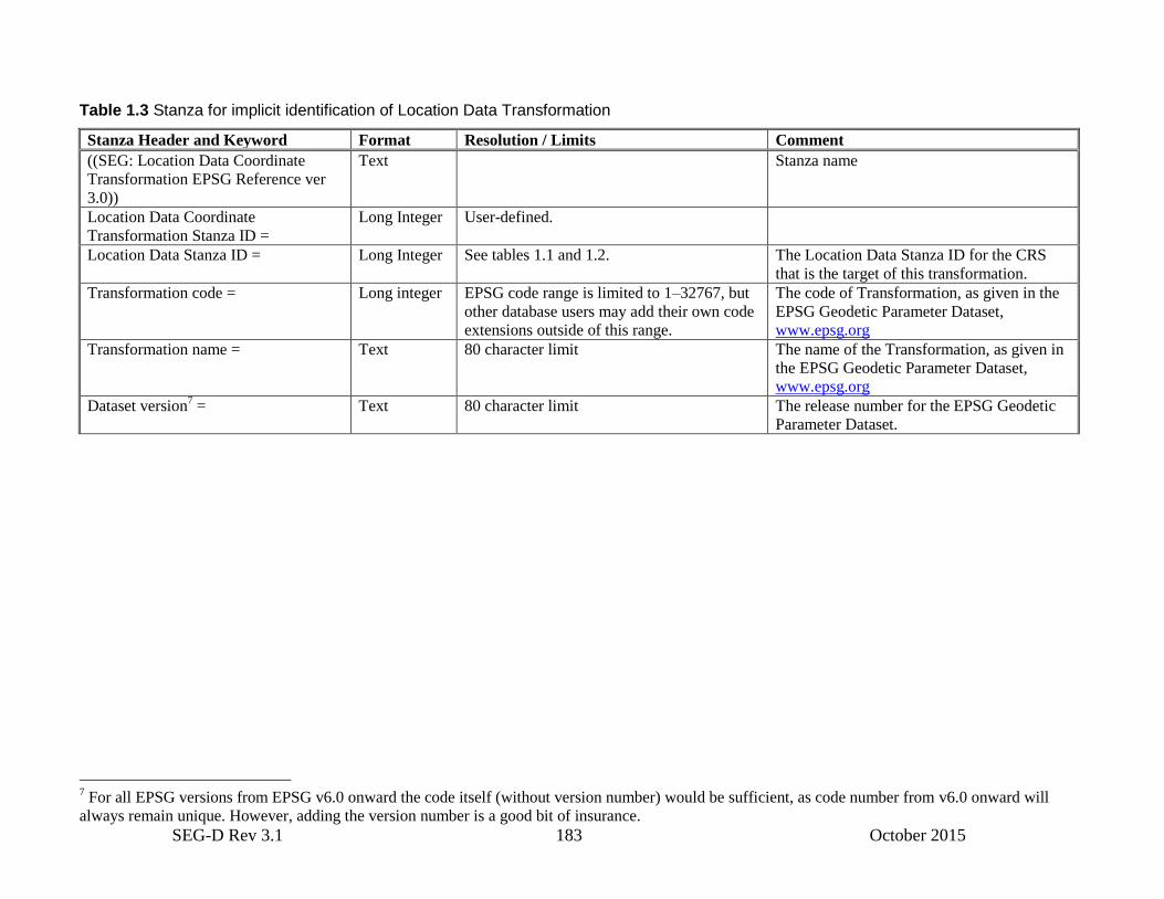
SEG-D Rev 3.1 183 October 2015
Table 1.3 Stanza for implicit identification of Location Data Transformation
Stanza Header and Keyword Format Resolution / Limits Comment
((SEG: Location Data Coordinate
Transformation EPSG Reference ver
3.0))
Text Stanza name
Location Data Coordinate
Transformation Stanza ID =
Long Integer User-defined.
Location Data Stanza ID = Long Integer See tables 1.1 and 1.2. The Location Data Stanza ID for the CRS
that is the target of this transformation.
Transformation code = Long integer EPSG code range is limited to 1–32767, but
other database users may add their own code
extensions outside of this range.
The code of Transformation, as given in the
EPSG Geodetic Parameter Dataset,
www.epsg.org
Transformation name = Text 80 character limit The name of the Transformation, as given in
the EPSG Geodetic Parameter Dataset,
www.epsg.org
Dataset version7 = Text 80 character limit The release number for the EPSG Geodetic
Parameter Dataset.
7 For all EPSG versions from EPSG v6.0 onward the code itself (without version number) would be sufficient, as code number from v6.0 onward will
always remain unique. However, adding the version number is a good bit of insurance.

SEG-D Rev 3.1 184 October 2015
Table 1.4 Stanza for explicit definition of Location Data Transformation
Stanza Header and Keyword Format Resolution / Limits Comment
((SEG: Location Data
Coordinate Transformation ver
3.0))
Text Stanza name
Location Data Coordinate
Transformation Stanza ID =
Long Integer User-defined. Normally all seismic work will be done with a single
transformation and thus the Stanza ID for this specific
transformation would be the only one populated.
Location Data Stanza ID = Long Integer See tables 1.1 and 1.2. The Location Data Stanza ID for the CRS that is the target of
this transformation.
Transformation type = From enumerated list:
transformation
concatenated operation
24 character limit, but must
be from enumerated list.
Transformation = a single operation that has been applied to
initial coordinates to derive values referred to the CRS
identified in the Location Data stanza.
Concatenated operation = a set of multiple transformations that
have been applied sequentially.
Transformation name = Text 80 character limit The name of the Transformation
Source CRS name = Text 80 character limit The name of the CRS from which coordinates have been
transformed, for example that used within the navigation
system (usually "WGS 84").
Target CRS name = Text 80 character limit The name of the CRS to which location data is referred. A
Location Data stanza or a Location Data EPSG Reference
stanza containing this name must precede this stanza.
Transformation version = Text 24 character limit The version of the transformation between the source and target
CRSs.
The following keywords are additionally required when transformation type = transformation:
Transformation method name = Text 50 character limit For example "Geocentric translations", "Position Vector 7-
param. Transformation", " Coordinate Frame rotation",
"NADCON", "NTv2".
Then either (a) the following keyword is additionally required for transformation methods which use grid files:
Transformation parameter file
name =
1 or more comma-
separated text strings
254 character limit Containing as many file names as the method requires. For
example for the NTv2 method one file name is required, for the
NADCON method two file names are required.
Or (b) the following keywords are additionally required for transformation methods other than those which use grid files:
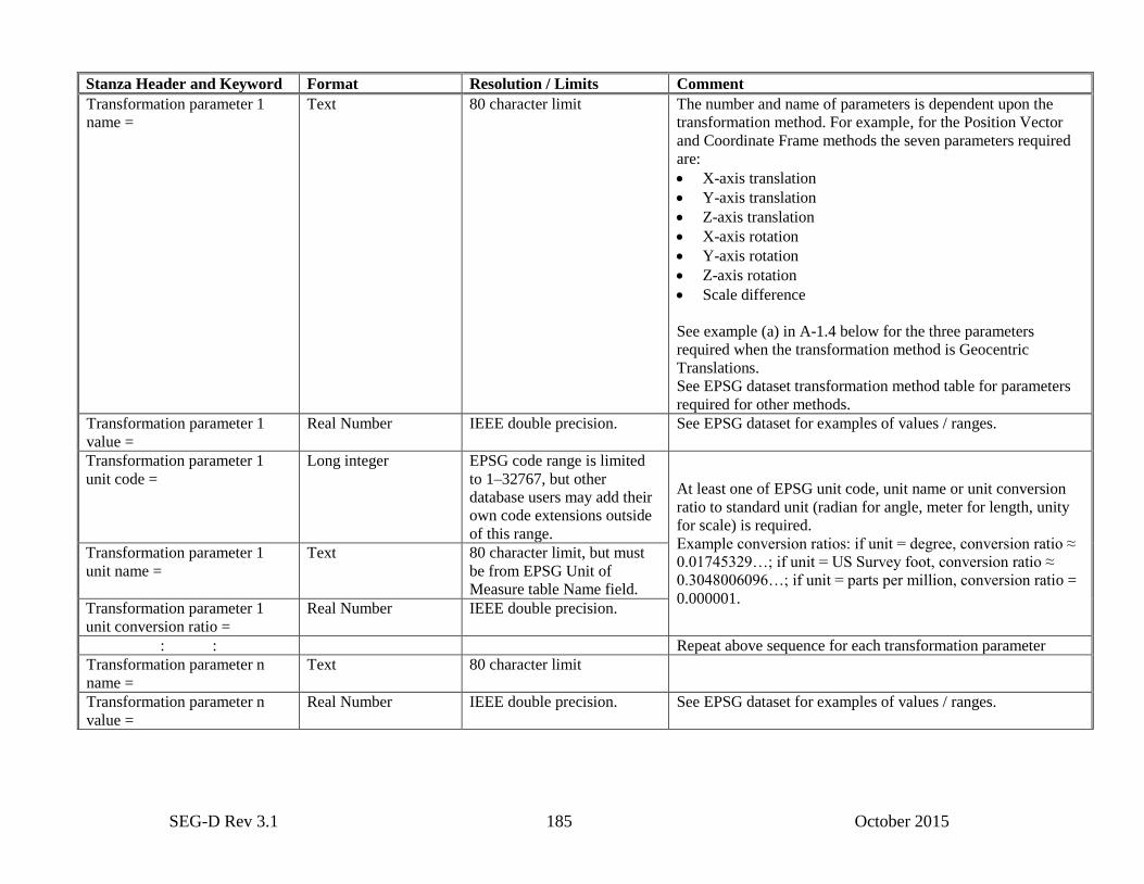
SEG-D Rev 3.1 185 October 2015
Stanza Header and Keyword Format Resolution / Limits Comment
Transformation parameter 1
name =
Text 80 character limit The number and name of parameters is dependent upon the
transformation method. For example, for the Position Vector
and Coordinate Frame methods the seven parameters required
are:
X-axis translation
Y-axis translation
Z-axis translation
X-axis rotation
Y-axis rotation
Z-axis rotation
Scale difference
See example (a) in A-1.4 below for the three parameters
required when the transformation method is Geocentric
Translations.
See EPSG dataset transformation method table for parameters
required for other methods.
Transformation parameter 1
value =
Real Number IEEE double precision. See EPSG dataset for examples of values / ranges.
Transformation parameter 1
unit code =
Long integer EPSG code range is limited
to 1–32767, but other
database users may add their
own code extensions outside
of this range.
At least one of EPSG unit code, unit name or unit conversion
ratio to standard unit (radian for angle, meter for length, unity
for scale) is required.
Example conversion ratios: if unit = degree, conversion ratio ≈
0.01745329…; if unit = US Survey foot, conversion ratio ≈
0.3048006096…; if unit = parts per million, conversion ratio =
0.000001.
Transformation parameter 1
unit name =
Text 80 character limit, but must
be from EPSG Unit of
Measure table Name field.
Transformation parameter 1
unit conversion ratio =
Real Number IEEE double precision.
: : Repeat above sequence for each transformation parameter
Transformation parameter n
name =
Text 80 character limit
Transformation parameter n
value =
Real Number IEEE double precision. See EPSG dataset for examples of values / ranges.
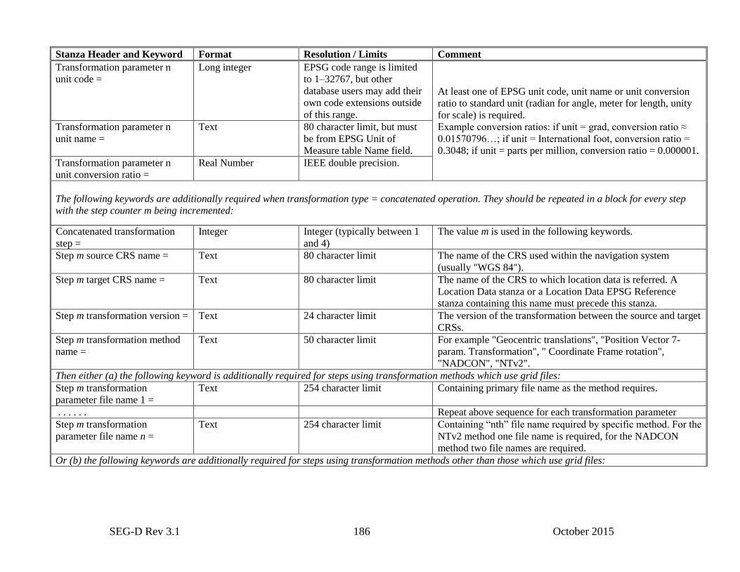
SEG-D Rev 3.1 186 October 2015
Stanza Header and Keyword Format Resolution / Limits Comment
Transformation parameter n
unit code =
Long integer EPSG code range is limited
to 1–32767, but other
database users may add their
own code extensions outside
of this range.
At least one of EPSG unit code, unit name or unit conversion
ratio to standard unit (radian for angle, meter for length, unity
for scale) is required.
Example conversion ratios: if unit = grad, conversion ratio ≈
0.01570796…; if unit = International foot, conversion ratio =
0.3048; if unit = parts per million, conversion ratio = 0.000001.
Transformation parameter n
unit name =
Text 80 character limit, but must
be from EPSG Unit of
Measure table Name field.
Transformation parameter n
unit conversion ratio =
Real Number IEEE double precision.
The following keywords are additionally required when transformation type = concatenated operation. They should be repeated in a block for every step
with the step counter m being incremented:
Concatenated transformation
step =
Integer Integer (typically between 1
and 4)
The value m is used in the following keywords.
Step m source CRS name = Text 80 character limit The name of the CRS used within the navigation system
(usually "WGS 84").
Step m target CRS name = Text 80 character limit The name of the CRS to which location data is referred. A
Location Data stanza or a Location Data EPSG Reference
stanza containing this name must precede this stanza.
Step m transformation version = Text 24 character limit The version of the transformation between the source and target
CRSs.
Step m transformation method
name =
Text 50 character limit For example "Geocentric translations", "Position Vector 7-
param. Transformation", " Coordinate Frame rotation",
"NADCON", "NTv2".
Then either (a) the following keyword is additionally required for steps using transformation methods which use grid files:
Step m transformation
parameter file name 1 =
Text 254 character limit Containing primary file name as the method requires.
. . . . . . Repeat above sequence for each transformation parameter
Step m transformation
parameter file name n =
Text 254 character limit Containing “nth” file name required by specific method. For the
NTv2 method one file name is required, for the NADCON
method two file names are required.
Or (b) the following keywords are additionally required for steps using transformation methods other than those which use grid files:
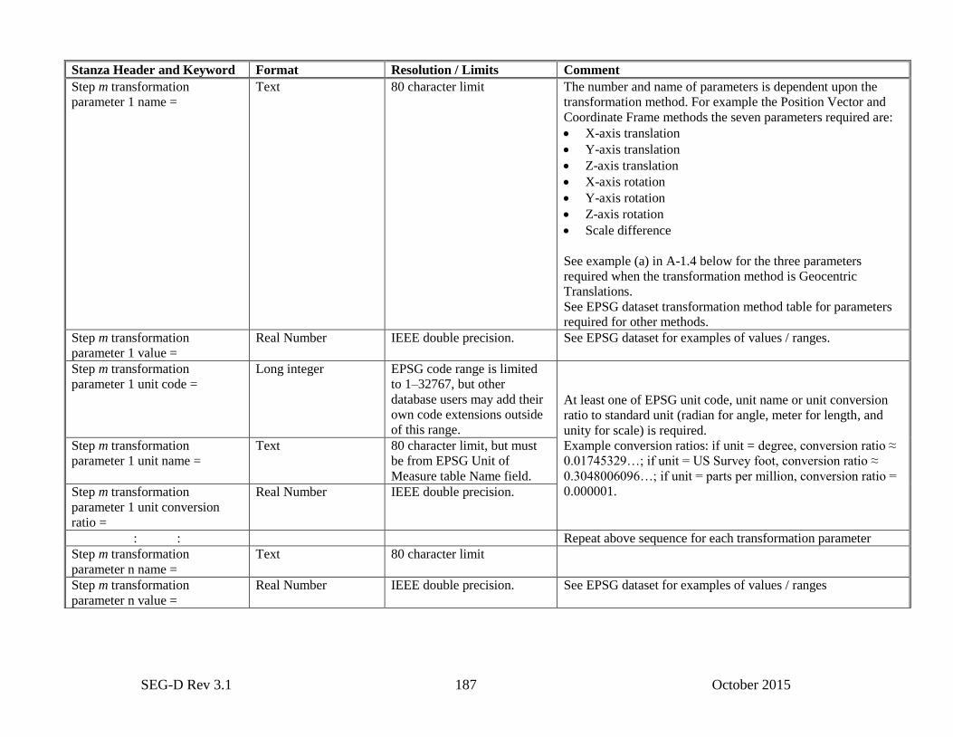
SEG-D Rev 3.1 187 October 2015
Stanza Header and Keyword Format Resolution / Limits Comment
Step m transformation
parameter 1 name =
Text 80 character limit The number and name of parameters is dependent upon the
transformation method. For example the Position Vector and
Coordinate Frame methods the seven parameters required are:
X-axis translation
Y-axis translation
Z-axis translation
X-axis rotation
Y-axis rotation
Z-axis rotation
Scale difference
See example (a) in A-1.4 below for the three parameters
required when the transformation method is Geocentric
Translations.
See EPSG dataset transformation method table for parameters
required for other methods.
Step m transformation
parameter 1 value =
Real Number IEEE double precision. See EPSG dataset for examples of values / ranges.
Step m transformation
parameter 1 unit code =
Long integer EPSG code range is limited
to 1–32767, but other
database users may add their
own code extensions outside
of this range.
At least one of EPSG unit code, unit name or unit conversion
ratio to standard unit (radian for angle, meter for length, and
unity for scale) is required.
Example conversion ratios: if unit = degree, conversion ratio ≈
0.01745329…; if unit = US Survey foot, conversion ratio ≈
0.3048006096…; if unit = parts per million, conversion ratio =
0.000001.
Step m transformation
parameter 1 unit name =
Text 80 character limit, but must
be from EPSG Unit of
Measure table Name field.
Step m transformation
parameter 1 unit conversion
ratio =
Real Number IEEE double precision.
: : Repeat above sequence for each transformation parameter
Step m transformation
parameter n name =
Text 80 character limit
Step m transformation
parameter n value =
Real Number IEEE double precision. See EPSG dataset for examples of values / ranges
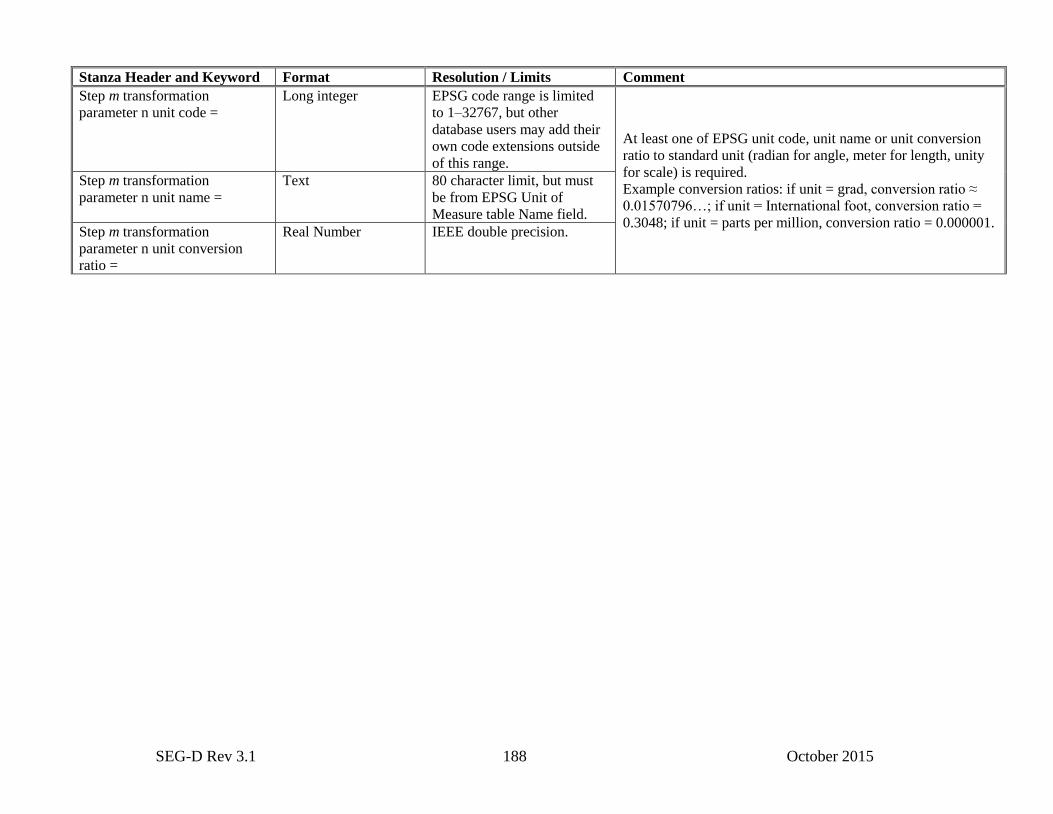
SEG-D Rev 3.1 188 October 2015
Stanza Header and Keyword Format Resolution / Limits Comment
Step m transformation
parameter n unit code =
Long integer EPSG code range is limited
to 1–32767, but other
database users may add their
own code extensions outside
of this range.
At least one of EPSG unit code, unit name or unit conversion
ratio to standard unit (radian for angle, meter for length, unity
for scale) is required.
Example conversion ratios: if unit = grad, conversion ratio ≈
0.01570796…; if unit = International foot, conversion ratio =
0.3048; if unit = parts per million, conversion ratio = 0.000001.
Step m transformation
parameter n unit name =
Text 80 character limit, but must
be from EPSG Unit of
Measure table Name field.
Step m transformation
parameter n unit conversion
ratio =
Real Number IEEE double precision.
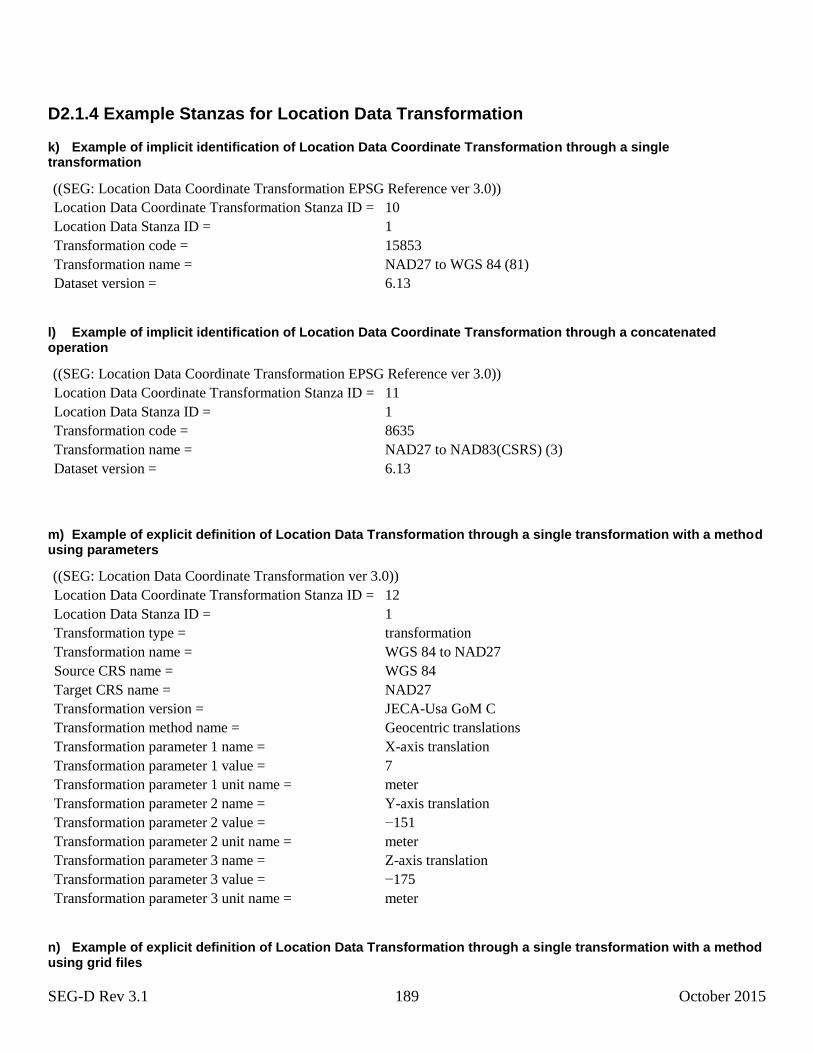
SEG-D Rev 3.1 189 October 2015
D2.1.4 Example Stanzas for Location Data Transformation
k) Example of implicit identification of Location Data Coordinate Transformation through a single transformation
((SEG: Location Data Coordinate Transformation EPSG Reference ver 3.0))
Location Data Coordinate Transformation Stanza ID = 10
Location Data Stanza ID = 1
Transformation code = 15853
Transformation name = NAD27 to WGS 84 (81)
Dataset version = 6.13
l) Example of implicit identification of Location Data Coordinate Transformation through a concatenated operation
((SEG: Location Data Coordinate Transformation EPSG Reference ver 3.0))
Location Data Coordinate Transformation Stanza ID = 11
Location Data Stanza ID = 1
Transformation code = 8635
Transformation name = NAD27 to NAD83(CSRS) (3)
Dataset version = 6.13
m) Example of explicit definition of Location Data Transformation through a single transformation with a method using parameters
((SEG: Location Data Coordinate Transformation ver 3.0))
Location Data Coordinate Transformation Stanza ID = 12
Location Data Stanza ID = 1
Transformation type = transformation
Transformation name = WGS 84 to NAD27
Source CRS name = WGS 84
Target CRS name = NAD27
Transformation version = JECA-Usa GoM C
Transformation method name = Geocentric translations
Transformation parameter 1 name = X-axis translation
Transformation parameter 1 value = 7
Transformation parameter 1 unit name = meter
Transformation parameter 2 name = Y-axis translation
Transformation parameter 2 value = −151
Transformation parameter 2 unit name = meter
Transformation parameter 3 name = Z-axis translation
Transformation parameter 3 value = −175
Transformation parameter 3 unit name = meter
n) Example of explicit definition of Location Data Transformation through a single transformation with a method using grid files
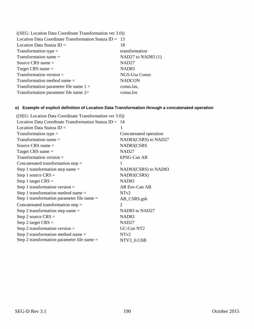
SEG-D Rev 3.1 190 October 2015
((SEG: Location Data Coordinate Transformation ver 3.0))
Location Data Coordinate Transformation Stanza ID = 13
Location Data Stanza ID = 18
Transformation type = transformation
Transformation name = NAD27 to NAD83 (1)
Source CRS name = NAD27
Target CRS name = NAD83
Transformation version = NGS-Usa Conus
Transformation method name = NADCON
Transformation parameter file name 1 = conus.las,
Transformation parameter file name 2= conus.los
o) Example of explicit definition of Location Data Transformation through a concatenated operation
((SEG: Location Data Coordinate Transformation ver 3.0))
Location Data Coordinate Transformation Stanza ID = 14
Location Data Stanza ID = 1
Transformation type = Concatenated operation
Transformation name = NAD83(CSRS) to NAD27
Source CRS name = NAD83(CSRS
Target CRS name = NAD27
Transformation version = EPSG-Can AB
Concatenated transformation step = 1
Step 1 transformation step name = NAD83(CSRS) to NAD83
Step 1 source CRS = NAD83(CSRS)
Step 1 target CRS = NAD83
Step 1 transformation version = AB Env-Can AB
Step 1 transformation method name = NTv2
Step 1 transformation parameter file name = AB_CSRS.gsb
Concatenated transformation step = 2
Step 2 transformation step name = NAD83 to NAD27
Step 2 source CRS = NAD83
Step 2 target CRS = NAD27
Step 2 transformation version = GC-Can NT2
Step 2 transformation method name = NTv2
Step 2 transformation parameter file name = NTV2_0.GSB

SEG-D Rev 3.1 191 October 2015
Appendix E: Examples and Calculations
E.1 Samples per scan type
Note:
This example is no longer valid as SEG-D rev 3.0 and above no longer has a base scan interval, and hence no longer has
a “samples per scan” value. The example is mainly here to support storing old formatted data in SEG-D rev 3.0+.
cs
SCSS1
2// s/c
where
S/S = samples per scan type
C/S = channels in this channel set (channel set descriptor Bytes 21 to 23)
2s/c
= samples per channel (in this channel set)
CS = number of channel sets in this scan type (general header #1 Byte 29 or general header #2 Byte 4 and 5)
For example, for a 2-msec base scan interval with 4 auxiliary channels at 2 msec, 96 channels at 2 msec and 12 channels
at ½ msec. There are three channel sets, so CS = 3.
S/S = C/S x 2s/c
+ C/S x 2s/c
+ …
cs = 1 cs = 2
S/S = 4 x 1 + 96 x 1 + 12 x 4
S/S = 4 + 96 + 48 = 148
Note that all scan types must have the same number of data samples.
E.2 Skew fields per scan type
Note:
This example is no longer valid as SEG-D rev 3.0 and above no longer has a base scan interval, and hence no longer has
a “samples per scan” value. The example is mainly here to support storing old formatted data with skew blocks in SEG-D
rev 3.0+.
SK = 32
/SS (If the quotient is not a whole number, round up to the next largest whole number)
where
SK = skew fields (of 32 bytes each) per scan type (general header Byte 30)
S/S = samples per scan (Appendix E1)
Substituting for S/S from Appendix E.1:
CS
SCSK1
2/32
1 s/c
(If the quotient is not a whole number, round up to the next largest whole number.)
where
CS = the number of channel sets in each scan type (general header #1 Byte 29 or #2 Byte 4 and 5)
C/S = channels in this channel set (channel set descriptor Bytes 21 to 23)
2s/c
= samples per channel in this channel set.
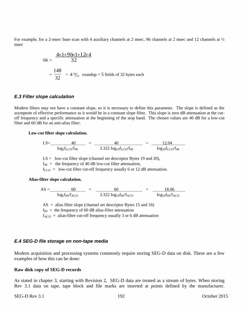
SEG-D Rev 3.1 192 October 2015
For example, for a 2-msec base scan with 4 auxiliary channels at 2 msec, 96 channels at 2 msec and 12 channels at ½
msec
SK = 3241219614
= 32
148 = 32
204 roundup = 5 fields of 32 bytes each
E.3 Filter slope calculation
Modern filters may not have a constant slope, so it is necessary to define this parameter. The slope is defined as the
asymptote of effective performance as it would be in a constant slope filter. This slope is zero dB attenuation at the cut-
off frequency and a specific attenuation at the beginning of the stop band. The chosen values are 40 dB for a low-cut
filter and 60 dB for an anti-alias filter.
Low-cut filter slope calculation.
LS= 40 = 40 = 12.04
log2fLCO/f40 3.322 log10fLCO/f40 log10fLCO/f40
LS = low-cut filter slope (channel set descriptor Bytes 19 and 20),
f40 = the frequency of 40 dB low-cut filter attenuation,
fLCO = low-cut filter cut-off frequency usually 6 or 12 dB attenuation.
Alias-filter slope calculation.
AS = 60 = 60 = 18.06
log2f60/fACO 3.322 log10f60/fACO log10f60/fACO
AS = alias filter slope (channel set descriptor Bytes 15 and 16)
f60 = the frequency of 60 dB alias-filter attenuation
fACO = alias-filter cut-off frequency usually 3 or 6 dB attenuation
E.4 SEG-D file storage on non-tape media
Modern acquisition and processing systems commonly require storing SEG-D data on disk. These are a few
examples of how this can be done:
Raw disk copy of SEG-D records
As stated in chapter 3, starting with Revision 2, SEG-D data are treated as a stream of bytes. When storing
Rev 3.1 data on tape, tape block and file marks are inserted at points defined by the manufacturer.
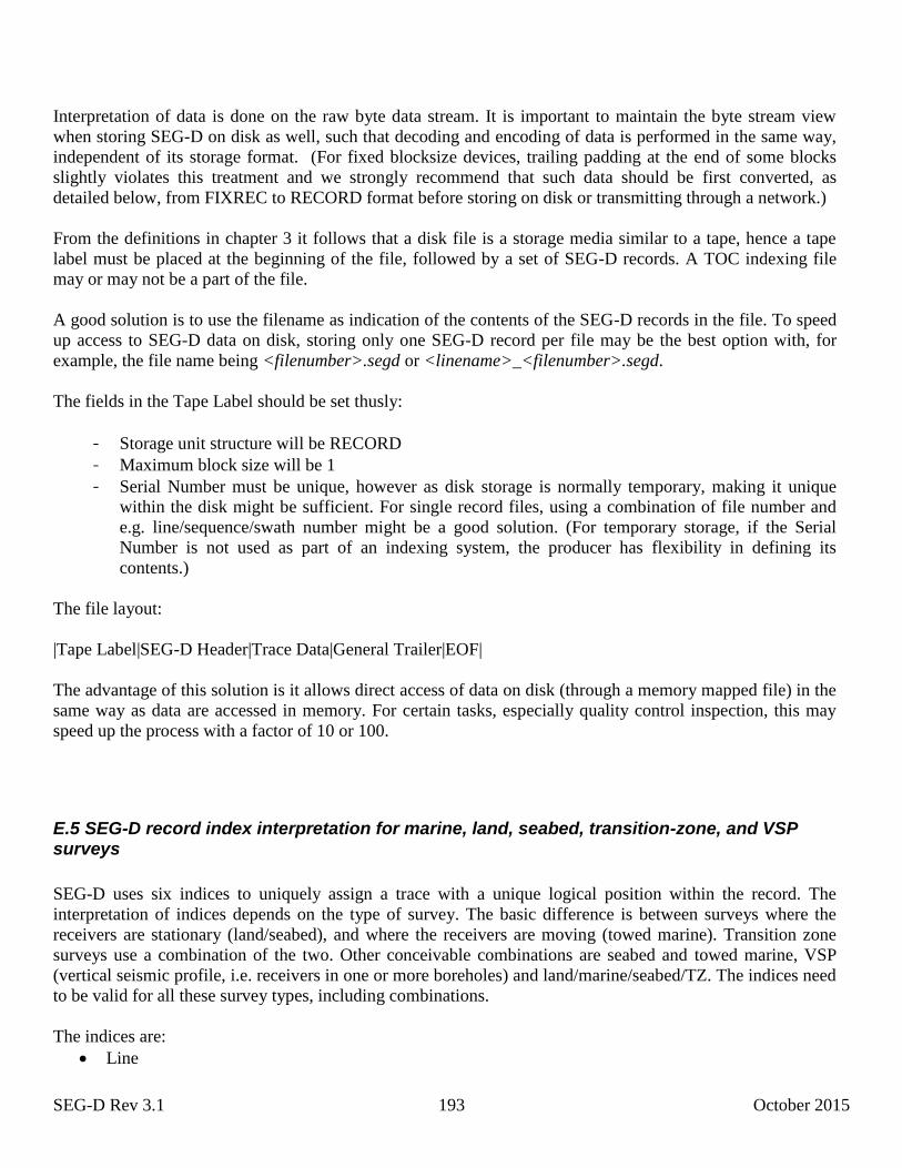
SEG-D Rev 3.1 193 October 2015
Interpretation of data is done on the raw byte data stream. It is important to maintain the byte stream view
when storing SEG-D on disk as well, such that decoding and encoding of data is performed in the same way,
independent of its storage format. (For fixed blocksize devices, trailing padding at the end of some blocks
slightly violates this treatment and we strongly recommend that such data should be first converted, as
detailed below, from FIXREC to RECORD format before storing on disk or transmitting through a network.)
From the definitions in chapter 3 it follows that a disk file is a storage media similar to a tape, hence a tape
label must be placed at the beginning of the file, followed by a set of SEG-D records. A TOC indexing file
may or may not be a part of the file.
A good solution is to use the filename as indication of the contents of the SEG-D records in the file. To speed
up access to SEG-D data on disk, storing only one SEG-D record per file may be the best option with, for
example, the file name being <filenumber>.segd or <linename>_<filenumber>.segd.
The fields in the Tape Label should be set thusly:
- Storage unit structure will be RECORD
- Maximum block size will be 1
- Serial Number must be unique, however as disk storage is normally temporary, making it unique
within the disk might be sufficient. For single record files, using a combination of file number and
e.g. line/sequence/swath number might be a good solution. (For temporary storage, if the Serial
Number is not used as part of an indexing system, the producer has flexibility in defining its
contents.)
The file layout:
|Tape Label|SEG-D Header|Trace Data|General Trailer|EOF|
The advantage of this solution is it allows direct access of data on disk (through a memory mapped file) in the
same way as data are accessed in memory. For certain tasks, especially quality control inspection, this may
speed up the process with a factor of 10 or 100.
E.5 SEG-D record index interpretation for marine, land, seabed, transition-zone, and VSP surveys
SEG-D uses six indices to uniquely assign a trace with a unique logical position within the record. The
interpretation of indices depends on the type of survey. The basic difference is between surveys where the
receivers are stationary (land/seabed), and where the receivers are moving (towed marine). Transition zone
surveys use a combination of the two. Other conceivable combinations are seabed and towed marine, VSP
(vertical seismic profile, i.e. receivers in one or more boreholes) and land/marine/seabed/TZ. The indices need
to be valid for all these survey types, including combinations.
The indices are:
Line

SEG-D Rev 3.1 194 October 2015
Point
Point Index
Group Index
Depth Index
Reshoot Index
Indices exists for both source (i.e. Source Point, Source Line), and receiver (i.e. Receiver Point, Receiver
Line).
The Group Index is used to indicate a trace belonging to a set of traces that need to be processed as a unit (and
are placed at the same position), e.g. three-component data that need to be rotated together.
The Reshoot Index is used to indicate a trace has been recorded earlier, and the data with the highest Reshoot
Index should be used in processing (normally).
Towed marine survey
A Marine survey is normally divided up in lines, and the survey is acquired by one or more vessels towing
one or more sources and one or more streamers. The lines are normally assigned an integer number. The
example below shows a complex survey using two streamer vessels with two sources each, and one source
vessel travelling behind one of the streamer vessels.
Line 1231
2
3
4
5
6
1
2
3
4
5
6
7
8
VSL1
VSL2
VSL3
Source
Streamer
10
0m
10
0m
50m
15
00
m 10000m
Figure showing a complex vessel configuration for a marine seismic survey. Note, figure
is not to scale
125m
Shot#
1244
8000m
Source / receiver line number
SEG-D Rev 3.1 195 October 2015
The receiver and source line number is give by the line number, in this case 123. In this example, the
fractional part of the source /receiver number will be used to indicate the nominal position of the equipment.
Using a pure logical numbering scheme is allowed, i.e. there are 12 separate equipment lines in the figure (8
streamer and 4 source). Equipment is e.g. allocated line number in steps of 0.5, starting counting from 123.0.
Streamer 1 has receiver line 123.0, Streamer 2 123.05, Source 1 and 5 has source line 123.1, Source 2 and
6 123.15, ..... Streamer 8 has 123.55.
However for this example, the logical positions are selected to reflect the actual offsets. The offset between
the outer streamers (1 and 8) are 1300 meters. 1 meter is selected to be 0.0005 logical units. Assuming
increasing line numbers downwards in the figure, Streamers are assigned the following line numbers:
1: 122.925, 2: 122.955, 3: 123.025, 4: 123.075, 5: 123.675, 6: 123.725, 7: 123.775, 8: 123.725.
Sources are assigned the following source line numbers:
1: 122.9875, 2: 123.0125, 4: 123.4875, 5: 123.5125, 5: 122.9875, 6: 123.0125
It is worth noting here that the number resolution in the receiver/source line numbers is not very high, so the
numbers above will be approximate.
Source / receiver point number
A similar strategy is used for source/receiver point number. The distance between sources 1 and 5 is 10000
meters. Receivers in the streamers are spaced at 12.5 meter intervals. 12.5 meters is chosen to be 1/1024
logical point units (The reason behind selecting 1/1024 as a unit is that this number is well represented in the
format). The marine acquisition line is divided up into shots (source events), with 25 meter spacing, the shot#
in the figure is 1244. The numbering starts from the first equipment (sources 1-4), counting backwards until
the last equipment (sources 5-6). The logical numbering will be the same independent of the line direction
(upline, i.e. shot# increasing, or downline, i.e shot# decreasing).
Sources 1-4 get Source Point Number 1244.0, sources 5-6 1244.78125.
Receiver 1 (on all streamers) is assigned Receiver Point Number 1244.00977, Receiver 2 1244.01074,
Receiver 3 1244.01172, ... Receiver 640 1244.63379
The Receiver Point Index will always be 1 for the marine survey.
Note: The source/receiver line/point number will only reflect the nominal position, actual position due to e.g.
streamer feather is not considered when determining the logical position determined by the indices. If actual
position is needed, the position may be stored in Position Blocks in Trace Headers.
Land
Land seismic surveys have been using Source and Receiver lines for many years, so no large example will be
given here. SEG-D may be used to map in the numbers currently used.
Seabed
Seabed surveys are a combination of a Land and Marine survey, where sensors are placed on the sea floor,
and a source vessel is moving around in the area, usually along Source Lines. Seabed covers several
operations, like seismic sensors placed on the sea floor temporarily in the form of streamers or separate sensor
units, permanently around installations, or electrical / magnetic sensors (EM survey).
SEG-D Rev 3.1 196 October 2015
The sensors are deployed in a grid defined by the Receiver Line and Point Numbers, similar to a Land survey.
Sources are moving in Source Lines similar to the example for Marine survey, and are assigned indices
accordingly. For continuous source efforts, like EM surveys, where the source fires continually, it is allowed
to set the Source Point Number to 0 if it does not fit at all. However, it is highly recommended to determine a
logical numbering scheme that allows the use of Source Point Number. This is one of the reasons why
splitting up the data into smaller records are recommended, e.g. to match the cycle of the source (see E.10
Electromagnetic (EM) survey) for more details.
Transition-zone
Transition zone may be viewed as a combination survey being parts Marine and parts Land survey. Indices
are assigned using Marine or Land methods where appropriate.
Downhole seismic / Vertical seismic profile
This covers all survey types where seismic sensors are inserted down a well. The sensors may be a dedicated
seismic string, or acquired as part of other downhole equipment. The survey may be a normal seismic survey,
Land or Marine, where the downhole data is acquired in conjunction with a larger system, or a dedicated well
centric survey, like a walkaway vertical seismic profile. The Source Line /Point Number is assigned as
normal, even with well centric surveys, the source moves in predetermined line.
Receiver Line / Point Number is assigned by giving the all receivers in the well the same Receiver Line and
Receiver Point Number, and use the Depth Index to indicate the order downhole. If the downhole string
contains more than 255 receivers, the Receiver Point Index is used to extend the numerical range of the Depth
Index. This allows a maximum of about 65000 receivers down a well. It is worth noting that all receivers in a
well are assigned the same Receiver Line /Point Number, even if the well is horizontal.
E.6 Trace edit example
Example of Trace Edits in General Trailer, built up by data from several systems, here by the acquisition
system ACQSYS, the quality control system AQC, and the positioning system NAVPOS. The edit block may
be extended by the different systems, or separate edit blocks may be created.
V SEGD Trace Edit v1.0
S 12:34:55 12-JAN-2007
W ACQSYS v2.2.3 build 231, M/S Unsinkable II
C These are the edits performed by online acquisition
H Killed traces
A killed trace
X 1;2;1-4
X 1;5;23,48-50,423
X 1;8;345
X 1;5-14;1
SEG-D Rev 3.1 197 October 2015
E END Killed traces
H Weak trace detection
A Seismic trace RMS < 1 uB
P SEIS_RMS(1,0.014)
R 1;5-14;1-558
X 1;3;123-135
X 1;15;33,55,231-234
E END Weak trace detection
S 14:15:00 12-JAN-2007
W AQC v6.4, operator John D. Operator
C These edits done by the online Quality Control system
H Noisy trace detection
A NOISY_TRACE(12,0.65)
C Noisy trace detection by comparing neighboring traces
C and performing frequency content analysis
R 1;5-14;1-558
X 1;6;1-15,234-238
X 1;8;1-15
E END Noisy trace detection
H Manual edits
A Manual edits
C Manual edits performed by operator
Y EXCLUDE
X 1;9;550-558
E END Manual edits
S 15:05:00 12-JAN-2007
W NAVPOS v1.2
C Edits done by positioning system
H Position verification
A GPS_VERIFY(4) GPS position quality verification
Y WARNING
X 1;14;1-558
C Comments entered by navigator:
C GPS positions for streamer 10 unreliable for shots 1201-1243
E END Position verification
T END SEGD Trace Edit
E.7 Source information in General Header or Trace Header
Source IDs/sets
Each source needed to be recorded must be assigned an ID, the same is required of any combined set of
sources.
Examples:
1. A SEG-D record contains four vibrators firing as a group. The record contains Source Description blocks
for each of the single vibrators, and the combined source group. The four vibrators have ids 2,12,13, and 16,
each belonging to source set 101 (i.e. vibrator group 101). The combined source is assigned the id 101, and it
does not belong to any source set, i.e. the source set is set to 0.
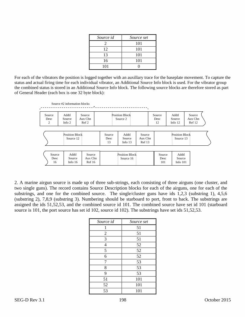
SEG-D Rev 3.1 198 October 2015
Source id Source set
2 101
12 101
13 101
16 101
101 0
For each of the vibrators the position is logged together with an auxillary trace for the baseplate movement. To capture the
status and actual firing time for each individual vibrator, an Additional Source Info block is used. For the vibrator group
the combined status is stored in an Additional Source Info block. The following source blocks are therefore stored as part
of General Header (each box is one 32 byte block):
2. A marine airgun source is made up of three sub-strings, each consisting of three airguns (one cluster, and
two single guns). The record contains Source Description blocks for each of the airguns, one for each of the
substrings, and one for the combined source. The single/cluster guns have ids 1,2,3 (substring 1), 4,5,6
(substring 2), 7,8,9 (substring 3). Numbering should be starboard to port, front to back. The substrings are
assigned the ids 51,52,53, and the combined source id 101. The combined source have set id 101 (starboard
source is 101, the port source has set id 102, source id 102). The substrings have set ids 51,52,53.
Source id Source set
1 51
2 51
3 51
4 52
5 52
6 52
7 53
8 53
9 53
51 101
52 101
53 101
Source
Desc
2
Addtl
Source
Info 2
Source
Aux Chn
Ref 2
Position Block
Source 2
Source
Desc
12
Addtl
Source
Info 12
Source
Aux Chn
Ref 12
Position Block
Source 12
Source
Desc
13
Addtl
Source
Info 13
Source
Aux Chn
Ref 13
Position Block
Source 13
Source
Desc
16
Addtl
Source
Info 16
Source
Aux Chn
Ref 16
Position Block
Source 16
Source
Desc
101
Addtl
Source
Info 101
Source #2 information blocks
SEG-D Rev 3.1 199 October 2015
101 0
To be able to see which sources belongs to which source sets, it is important to give the source set, and the
combined source ids the same value. This means SEG-D rev 3.1 supports up to 255 different single sources
and source sets/groups.
Source information should match SPS definitions.
To be able to cope with multiple source events during the record, Source Information blocks can be recorded
as part of the Trace Extension Header (instead of in the General Header). The Additional Source Info block
must then be present for each Source Information block, and the timestamp (bytes 1–8) filled in properly to
indicate which sample the source event happened. The relevant source description blocks must also be
inserted into all traces relating to source (source signatures, baseplate measurements, raw nearfield
hydrophone data etc.), though they may also be recorded as part of any other (seismic/auxiliary) trace.
E.8 Extended Recording Mode example
Extended recording mode is mostly designed for situations where lack of resources makes creation of multiple
SEGD records a complicated or impossible task, e.g. in embedded systems where memory resources or
memory model making storing meta-information intermixed with the data difficult.
Extended recording mode allows data to be recorded in blocks of up to 4,294,967,295 samples, containing a
small trace header (84 byte minimum) followed by up to 4,294,967,295 samples of data.
Consider the following sensor node:
X Y Z P
Sampling
Control
DSP
Memory
uC
Memory
Sensor Node

SEG-D Rev 3.1 200 October 2015
The node contains one microcontroller (μC) with attached memory for control, monitoring, quality control
and external communication, and one digital signal processor (DSP) with attached memory for sampling and
data filtering from 4 sensors (a 3 component accelerometer and one hydrophone).
The node is deployed on the sea floor, and will remain there for a maximum of two weeks (1,209,600
seconds) before being picked up. Extended recording mode allows up to 65535 channelsets (or time blocks) to
be acquired in one record, each channelset being up to 4,294,967,295 samples long. As the node has 4
different channel types, which have to be stored in separate channelsets, the available number of time blocks
in extended Recording mode is 65535/4=16383. To get the minimum time block/channelset length for this
system we calculate 1209600/16383 = 73.8 seconds
One may then safely decide to choose a trace size of 120 seconds. This creates a suitable sized trace which fit
the memory model of the DSP well, has a good safety margin (can be deployed for a maximum of 22 days),
and has a good overhead to data ratio. In addition the system is created such that in case of a memory
problem, only 120 consecutive seconds of data will be lost at a time.
The microcontroller is responsible for creating the SEG-D record header and keep it in memory during the
acquisition. Whenever a new channelset is needed, the DSP notifies the microcontroller, which creates the 4
channelset descriptors. The DSP creates 4 new trace headers in its memory, each consisting of a Trace Header
(20 bytes), Trace Header Extension #1 (32 bytes), and a Timestamp Header (32 byte). It then starts writing
trace data into the new traces.
The microcontroller monitors several other sensors during the acquisition, including temperature, box
pressure, leakage sensor, power status, compass readings, tilt/orientation measurements, clock drift etc. This
information is stored in the SEG-D record Extended Header in a manufacturer specific format.
When the data is downloaded from the node, the microcontroller first sends the header data stored in its
memory, then reads the trace data from the DSP such that the download software receives a complete SEG-D
record.
E.9 SEG-D timestamp calculation
/* SEG-D UTC <--> GPS conversion * * The following is ANSI C++ code. * It should be easily translated to most other common languages like Java, C, C#, Fortran, Perl * * Disclaimer: * This example code is provided “as is” without warranty of any kind for free unlimited use. * It may be copied, modified and integrated into proprietary software freely without cost. * * Users of this code are themselves responsible for updating the tables dayLeapArr, * tsLeapArr and tsJan1YearArr when new leap seconds are added to Coordinated Universal Time (UTC) * ref. https://en.wikipedia.org/wiki/Leap_second */ #include <stdio.h> #include <limits.h> #include <stdlib.h> #if LONG_MAX <= 2147483647L
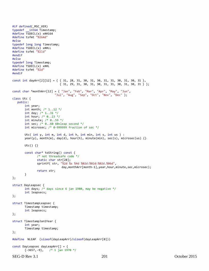
SEG-D Rev 3.1 201 October 2015
#if defined(_MSC_VER) typedef __int64 Timestamp; #define TSDECL(x) x##i64 #define tsfmt "%I64d" #else typedef long long Timestamp; #define TSDECL(x) x##LL #define tsfmt "%lld" #endif #else typedef long Timestamp; #define TSDECL(x) x##L #define tsfmt "%ld" #endif const int dayArr[2][12] = { { 31, 28, 31, 30, 31, 30, 31, 31, 30, 31, 30, 31 }, { 31, 29, 31, 30, 31, 30, 31, 31, 30, 31, 30, 31 } }; const char *monthArr[12] = { "Jan", "Feb", "Mar", "Apr", "May", "Jun", "Jul", "Aug", "Sep", "Oct", "Nov", "Dec" }; class Utc { public: int year; int month; /* 1..12 */ int day; /* 1..31 */ int hour; /* 0..23 */ int minute; /* 0..59 */ int sec; /* 0..60 60=leap second */ int microsec; /* 0-999999 fraction of sec */ Utc( int y, int m, int d, int h, int min, int s, int us ) : year(y), month(m), day(d), hour(h), minute(min), sec(s), microsec(us) {} Utc() {} const char* toString() const { /* not threadsafe code */ static char str[28]; sprintf( str, "%2d %s %4d %02d:%02d:%02d.%06d", day,monthArr[month-1],year,hour,minute,sec,microsec); return str; } }; struct DayLeapsec { int days; /* days since 6 jan 1980, may be negative */ int leapsecs; }; struct TimestampLeapsec { Timestamp timestamp; int leapsecs; }; struct TimestampJan1Year { int year; Timestamp timestamp; }; #define NLEAP (sizeof(dayLeapArr)/sizeof(dayLeapArr[0])) const DayLeapsec dayLeapArr[] = { {-3657, -9}, /* 1 jan 1970 */
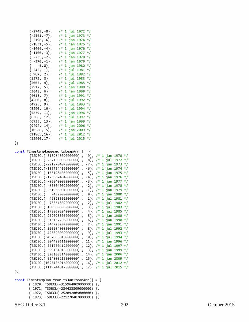
SEG-D Rev 3.1 202 October 2015
{-2745, -8}, /* 1 jul 1972 */ {-2561, -7}, /* 1 jan 1973 */ {-2196, -6}, /* 1 jan 1974 */ {-1831, -5}, /* 1 jan 1975 */ {-1466, -4}, /* 1 jan 1976 */ {-1100, -3}, /* 1 jan 1977 */ { -735, -2}, /* 1 jan 1978 */ { -370, -1}, /* 1 jan 1979 */ { -5, 0}, /* 1 jan 1980 */ { 542, 1}, /* 1 jul 1981 */ { 907, 2}, /* 1 jul 1982 */ {1272, 3}, /* 1 jul 1983 */ {2003, 4}, /* 1 jul 1985 */ {2917, 5}, /* 1 jan 1988 */ {3648, 6}, /* 1 jan 1990 */ {4013, 7}, /* 1 jan 1991 */ {4560, 8}, /* 1 jul 1992 */ {4925, 9}, /* 1 jul 1993 */ {5290, 10}, /* 1 jul 1994 */ {5839, 11}, /* 1 jan 1996 */ {6386, 12}, /* 1 jul 1997 */ {6935, 13}, /* 1 jan 1999 */ {9492, 14}, /* 1 jan 2006 */ {10588, 15}, /* 1 jan 2009 */ {11865, 16}, /* 1 jul 2012 */ {12960, 17} /* 1 jul 2015 */ }; const TimestampLeapsec tsLeapArr[] = { {TSDECL(-315964809000000) , -9}, /* 1 jan 1970 */ {TSDECL(-237168008000000) , -8}, /* 1 jul 1972 */ {TSDECL(-221270407000000) , -7}, /* 1 jan 1973 */ {TSDECL(-189734406000000) , -6}, /* 1 jan 1974 */ {TSDECL(-158198405000000) , -5}, /* 1 jan 1975 */ {TSDECL(-126662404000000) , -4}, /* 1 jan 1976 */ {TSDECL( -95040003000000) , -3}, /* 1 jan 1977 */ {TSDECL( -63504002000000) , -2}, /* 1 jan 1978 */ {TSDECL( -31968001000000) , -1}, /* 1 jan 1979 */ {TSDECL( -432000000000) , 0}, /* 1 jan 1980 */ {TSDECL( 46828801000000) , 1}, /* 1 jul 1981 */ {TSDECL( 78364802000000) , 2}, /* 1 jul 1982 */ {TSDECL( 109900803000000) , 3}, /* 1 jul 1983 */ {TSDECL( 173059204000000) , 4}, /* 1 jul 1985 */ {TSDECL( 252028805000000) , 5}, /* 1 jan 1988 */ {TSDECL( 315187206000000) , 6}, /* 1 jan 1990 */ {TSDECL( 346723207000000) , 7}, /* 1 jan 1991 */ {TSDECL( 393984008000000) , 8}, /* 1 jul 1992 */ {TSDECL( 425520009000000) , 9}, /* 1 jul 1993 */ {TSDECL( 457056010000000) , 10}, /* 1 jul 1994 */ {TSDECL( 504489611000000) , 11}, /* 1 jan 1996 */ {TSDECL( 551750412000000) , 12}, /* 1 jul 1997 */ {TSDECL( 599184013000000) , 13}, /* 1 jan 1999 */ {TSDECL( 820108814000000) , 14}, /* 1 jan 2006 */ {TSDECL( 914803215000000) , 15}, /* 1 jan 2009 */ {TSDECL(1025136016000000) , 16}, /* 1 jul 2012 */ {TSDECL(1119744017000000) , 17} /* 1 jul 2015 */ }; const TimestampJan1Year tsJan1YearArr[] = { { 1970, TSDECL(-315964809000000) }, { 1971, TSDECL(-284428809000000) }, { 1972, TSDECL(-252892809000000) }, { 1973, TSDECL(-221270407000000) },
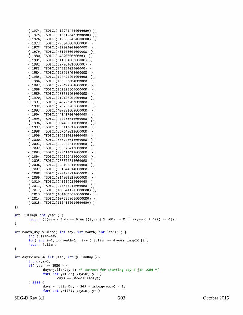
SEG-D Rev 3.1 203 October 2015
{ 1974, TSDECL(-189734406000000) }, { 1975, TSDECL(-158198405000000) }, { 1976, TSDECL(-126662404000000) }, { 1977, TSDECL(-95040003000000) }, { 1978, TSDECL(-63504002000000) }, { 1979, TSDECL(-31968001000000) }, { 1980, TSDECL(-432000000000) }, { 1981, TSDECL(31190400000000) }, { 1982, TSDECL(62726401000000) }, { 1983, TSDECL(94262402000000) }, { 1984, TSDECL(125798403000000) }, { 1985, TSDECL(157420803000000) }, { 1986, TSDECL(188956804000000) }, { 1987, TSDECL(220492804000000) }, { 1988, TSDECL(252028805000000) }, { 1989, TSDECL(283651205000000) }, { 1990, TSDECL(315187206000000) }, { 1991, TSDECL(346723207000000) }, { 1992, TSDECL(378259207000000) }, { 1993, TSDECL(409881608000000) }, { 1994, TSDECL(441417609000000) }, { 1995, TSDECL(472953610000000) }, { 1996, TSDECL(504489611000000) }, { 1997, TSDECL(536112011000000) }, { 1998, TSDECL(567648012000000) }, { 1999, TSDECL(599184013000000) }, { 2000, TSDECL(630720013000000) }, { 2001, TSDECL(662342413000000) }, { 2002, TSDECL(693878413000000) }, { 2003, TSDECL(725414413000000) }, { 2004, TSDECL(756950413000000) }, { 2005, TSDECL(788572813000000) }, { 2006, TSDECL(820108814000000) }, { 2007, TSDECL(851644814000000) }, { 2008, TSDECL(883180814000000) }, { 2009, TSDECL(914803215000000) }, { 2010, TSDECL(946339215000000) }, { 2011, TSDECL(977875215000000) }, { 2012, TSDECL(1009411215000000) }, { 2013, TSDECL(1041033616000000) }, { 2014, TSDECL(1072569616000000) }, { 2015, TSDECL(1104105616000000) } }; int isLeap( int year ) { return (((year) % 4) == 0 && (((year) % 100) != 0 || ((year) % 400) == 0)); } int month_dayToJulian( int day, int month, int leapIX ) { int julian=day; for( int i=0; i<(month-1); i++ ) julian += dayArr[leapIX][i]; return julian; } int daysSinceT0( int year, int julianDay ) { int days=0; if( year >= 1980 ) { days=julianDay-6; /* correct for starting day 6 jan 1980 */ for( int y=1980; y<year; y++ ) days += 365+isLeap(y); } else { days = julianDay - 365 - isLeap(year) - 6; for( int y=1979; y>year; y--)

SEG-D Rev 3.1 204 October 2015
days -= 365+isLeap(y); } return days; } int leapSecs( int daysSinceT0 ) { for( int i=NLEAP-1; i>=0; i-- ) { if(daysSinceT0 >= dayLeapArr[i].days ) { /* fprintf(stdout, "leapSecs: %d\n", dayLeapArr[i].leapsecs); */ return dayLeapArr[i].leapsecs; } } fprintf(stderr, "Illegal number in leapSec calculation, is date after 1970?\n"); return 0; /* should never happen with legal SEG-D timestamps, throw exception here */ } int leapSecs( Timestamp ts ) { for( int i=NLEAP-1; i>=0; i-- ) { if(ts >= tsLeapArr[i].timestamp ) { /* fprintf(stdout, "leapSecs: %d\n", tsLeapArr[i].leapsecs); */ return tsLeapArr[i].leapsecs; } } fprintf(stderr, "Illegal number in leapSec calculation, is date after 1970?\n"); return 0; /* should never happen with legal SEG-D timestamps, throw exception here */ } Timestamp utcToTimestamp( const Utc& utc ) { int leapIX = isLeap(utc.year) ? 1 : 0; /* february */ int julian = month_dayToJulian(utc.day,utc.month,leapIX); int nd = daysSinceT0(utc.year,julian); /* nd negative if date before 6 jan 1980 */ Timestamp ts = 1000000*(Timestamp)((Timestamp)nd*24*3600 + utc.hour*3600 + utc.minute*60 + utc.sec) + utc.microsec; return ts + leapSecs(nd)*1000000; } Utc timestampToUtc( Timestamp ts ) { Utc result(0,0,0,0,0,0,0); int iy, nd, md, im; int leapIX; Timestamp tsJan1; for(iy = 0 ; iy < (sizeof(tsJan1YearArr)/sizeof(tsJan1YearArr[0])); ++iy) { if(tsJan1YearArr[iy].timestamp <= ts) { result.year = tsJan1YearArr[iy].year; } else { break; } } /* if off the end of the charts, return all zeros */ if(result.year == 0) return result; else tsJan1 = tsJan1YearArr[iy-1].timestamp; /* reduce to number of microseconds since beginning of year */ ts -= (1000000 * leapSecs(ts)); tsJan1 -= (1000000 * leapSecs(tsJan1)); ts -= tsJan1; /* extract microseconds */ result.microsec = (int) (ts%1000000); ts -= result.microsec; ts /= 1000000;
SEG-D Rev 3.1 205 October 2015
/* extract seconds */ result.sec = (int) (ts%60); ts -= result.sec; ts /= 60; /* extract minutes */ result.minute = (int) (ts%60); ts -= result.minute; ts /= 60; /* extract hours */ result.hour = (int) (ts%24); ts /= 24; /* figure month and day from number of days since start of year */ nd = (int) (ts); md = 0; leapIX = isLeap(result.year) ? 1 : 0; /* february */ for( im = 0; im < 12; ++im ) { if( md > nd ) break; md += dayArr[leapIX][im]; } result.month = im; result.day = 1 + nd + dayArr[leapIX][im-1] - md; if(result.day == 32) { /* leap second */ result.day = 31; result.hour = 23; result.minute = 59; result.sec = 60; } return result; } extern "C" { void GPStoDate(Timestamp ts, int *year, int *month, int *day, int *hour, int *minute, int *sec, int *microsec) { Utc testTime = timestampToUtc( ts ); *year = testTime.year; *month = testTime.month; *day = testTime.day; *hour = testTime.hour; *minute = testTime.minute; *sec = testTime.sec; *microsec = testTime.microsec; } } #ifdef TEST int main(int argc, char **argv) { int yrlist[] = { 1970, 1971, 1972, 1973, 1974, 1975, 1976, 1977, 1978, 1979, 1980, 1981, 1982, 1983, 1984, 1985, 1986, 1987, 1988, 1989, 1990, 1991, 1992, 1993, 1994, 1995, 1996, 1997, 1998, 1999, 2000, 2001, 2002, 2003, 2004, 2005, 2006, 2007, 2008, 2009, 2010, 2011, 2012 }; int mnlist[] = { 1, 1, 1, 1, 1, 1, 1, 1, 1, 1, 1, 1, 1, 1, 1, 1, 1, 1, 1, 1, 1, 1, 1, 1, 1, 1, 1, 1, 1, 1, 1, 1, 1, 1, 1, 1, 1, 1, 1, 1, 1, 1, 1 }; size_t i; Utc testTime(2005,12,31,23,59,60,0);
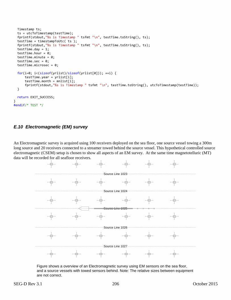
SEG-D Rev 3.1 206 October 2015
Timestamp ts; ts = utcToTimestamp(testTime); fprintf(stdout,"%s is Timestamp " tsfmt "\n", testTime.toString(), ts); testTime = timestampToUtc( ts ); fprintf(stdout,"%s is Timestamp " tsfmt "\n", testTime.toString(), ts); testTime.day = 1; testTime.hour = 0; testTime.minute = 0; testTime.sec = 0; testTime.microsec = 0; for(i=0; i<(sizeof(yrlist)/sizeof(yrlist[0])); ++i) { testTime.year = yrlist[i]; testTime.month = mnlist[i]; fprintf(stdout,"%s is Timestamp " tsfmt "\n", testTime.toString(), utcToTimestamp(testTime)); } return EXIT_SUCCESS; } #endif/* TEST */
E.10 Electromagnetic (EM) survey
An Electromagnetic survey is acquired using 100 receivers deployed on the sea floor, one source vessel towing a 300m
long source and 20 receivers connected to a streamer towed behind the source vessel. This hypothetical controlled source
electromagnetic (CSEM) setup is chosen to show all aspects of an EM survey. At the same time magnetotelluric (MT)
data will be recorded for all seafloor receivers.
Source Line 1025
Figure shows a overview of an Electromagnetic survey using EM sensors on the sea floor,
and a source vessels with towed sensors behind. Note: The relative sizes between equipment
are not correct.
Source Line 1023
Source Line 1024
Source Line 1026
Source Line 1027
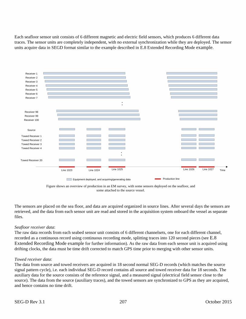
SEG-D Rev 3.1 207 October 2015
Each seafloor sensor unit consists of 6 different magnetic and electric field sensors, which produces 6 different data
traces. The sensor units are completely independent, with no external synchronization while they are deployed. The sensor
units acquire data in SEGD format similar to the example described in E.8 Extended Recording Mode example.
Time
:
Receiver 1
Receiver 2
Receiver 3
Receiver 4
Receiver 5
Receiver 6
Receiver 7
Receiver 98
Receiver 99
Receiver 100
Source
Towed Receiver 1
Towed Receiver 2
Towed Receiver 3
Towed Receiver 4
Towed Receiver 20
:
Equipment deployed, and acquiring/generating data Production line
Line 1023 Line 1024 Line 1025 Line 1026 Line 1027
Figure shows an overview of production in an EM survey, with some sensors deployed on the seafloor, and
some attached to the source vessel.
The sensors are placed on the sea floor, and data are acquired organized in source lines. After several days the sensors are
retrieved, and the data from each sensor unit are read and stored in the acquisition system onboard the vessel as separate
files.
Seafloor receiver data:
The raw data records from each seabed sensor unit consists of 6 different channelsets, one for each different channel,
recorded as a continuous record using continuous recording mode, splitting traces into 120 second pieces (see E.8
Extended Recording Mode example for further information). As the raw data from each sensor unit is acquired using
drifting clocks, the data must be time drift corrected to match GPS time prior to merging with other sensor units.
Towed receiver data:
The data from source and towed receivers are acquired in 18 second normal SEG-D records (which matches the source
signal pattern cycle), i.e. each individual SEG-D record contains all source and towed receiver data for 18 seconds. The
auxiliary data for the source consists of the reference signal, and a measured signal (electrical field sensor close to the
source). The data from the source (auxiliary traces), and the towed sensors are synchronized to GPS as they are acquired,
and hence contains no time drift.
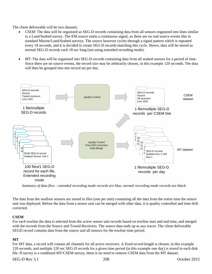
SEG-D Rev 3.1 208 October 2015
The client deliverable will be two datasets:
CSEM: The data will be organized as SEG-D records containing data from all sensors organized into lines similar
to a Land/Seabed survey. The EM source emits a continuous signal, so there are no real source events like in
standard Marine/Land/Seabed surveys. The source however cycles through a signal pattern which is repeated
every 18 seconds, and it is decided to create SEG-D records matching this cycle. Hence, data will be stored as
normal SEG-D records each 18 sec long (not using extended recording mode).
MT: The data will be organized into SEG-D records containing data from all seabed sensors for a period of time.
Since there are no source events, the record size may be arbitrarily chosen, in this example 120 seconds. The data
will then be grouped into one record set per day.
SEG-D records
Source
Towed receivers
Line 1052
RAW SEG-D records
Seabed Sensor Unit 1
100 files/1 SEG-D
record for each file,
Extended recording
mode
SEG-D records
Source
All receivers
Line 1052
CSEM
dataset
SEG-D records
Sea floor recv 1-100
Day 1
MT dataset
Quality Control
Quality Control
Time Drift Correction
Data Merge
SEG-D records
Sea floor recv 1-100
Day 1SEG-D records
Sea floor recv 1-100
Day 1SEG-D records
Sea floor recv 1-100
Day 1SEG-D records
Seabed recv 1-100
Day 1
1 file/multiple
SEG-D records1 file/multiple SEG-D
records per CSEM line
1 file/multiple SEG-D
records per day
RAW SEG-D records
Seabed Sensor Unit 1RAW SEG-D records
Seabed Sensor Unit 1RAW SEG-D record
Seabed Sensor Unit 1RAW SEG-D record
Seabed Sensor Unit 1
Summary of data flow - extended recording mode records are blue, normal recording mode records are black.
The data from the seafloor sensors are stored in files (one per unit) containing all the data from the entire time the sensor
unit was deployed. Before the data from a sensor unit can be merged with other data, it is quality controlled and time drift
corrected.
CSEM
For each towline the data is selected from the active sensor unit records based on towline start and end time, and merged
with the records from the Source and Towed Receivers. The source data ends up as aux traces. The client deliverable
SEGD record contains data from the source and all sensors for the towline time period.
MT
For MT data, a record will contain all channels for all active receivers. A fixed record length is chosen, in this example
120 seconds, and multiple 120 sec SEG-D records for a given time period (in this example one day) is stored in each disk
file. If survey is a combined MT/CSEM survey, there is no need to remove CSEM data from the MT dataset.
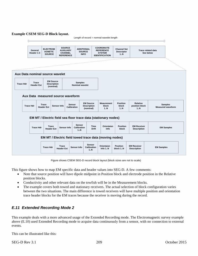
SEG-D Rev 3.1 209 October 2015
Example CSEM SEG-D Block layout.
General
Header 1-3
Channel Set
Descriptor
1..N
Trace HdrTrace
Header ExtSensor Info
Sensor
Calibration
1..N
Orientaion
Info
ELECTROM
AGNETIC
SOURCE
SOURCE
AUXILIARY
CHANNEL
REFERENCE
Trace related data
See below
EM MT / Electric field sea floor trace data (stationary nodes)
Time
Drift
Aux Data nominal source wavelet
Trace HdrTrace
Header Ext
EM Receiver
Description
EM Source
Description
(nominal)
Length of record = nomnal wavelet length
Position
block
Aux Data measured source waveform
Trace HdrTrace
Header ExtSensor Info
Sensor
Calibration
Relative
position block
1..N
Position
block
1..N
Samples
Nominal wavelet
Samples
Measured waveform
EM Samples
ADDITIONAL
SOURCE
INFO
COORDINATE
REFERENCE
SYSTEM
IDENTIFICATION
Meaurement
block
1..N
Figure shows CSEM SEG-D record block layout (block sizes are not to scale)
Trace HdrTrace
Header ExtSensor Info
Sensor
Calibration
1..N
Orientaion
Info 1..N
EM MT / Electric field towed trace data (moving nodes)
EM Receiver
Description
Position
block 1..NEM Samples
EM Source
Description
(nominal)
This figure shows how to map EM specific data and header values into SEG-D. A few comments:
Note that source position will have dipole midpoint in Position block and electrode position in the Relative
position blocks.
Conductivity and other relevant data on the towfish will be in the Measurement blocks.
The example covers both towed and stationary receivers. The actual selection of block configuration varies
between the two situations. The main difference is towed receivers will have multiple position and orientation
trace header blocks for the EM traces because the receiver is moving during the record.
E.11 Extended Recording Mode 2
This example deals with a more advanced usage of the Extended Recording mode. The Electromagnetic survey example
above (E.10) used Extended Recording mode to acquire data continuously from a sensor, with no connection to external
events.
This can be illustrated like this:

SEG-D Rev 3.1 210 October 2015
Here T0x refers to the timestamp (Timestamp block) in each channelset, and the record length RL is the length of each
Channel Set. Hence the channel is acquired as one long continuous trace.
Land vibrator survey using autonomous acquisition nodes
Now consider a Land survey using vibrators as sources and a seismic spread consisting of autonomous acquisition
nodes.
The individual vibrator acquires an auxillary trace (base plate movement) every shot, which needs to be stored on the
vibrator until the end of the day when it is downloaded. The seismic sensors acquire data for several days before it is
picked up and the data downloaded.
The firing time T0 is distributed from the vibrators to the acquisition nodes which then records data for a certain time
(record length RL). For technical reasons the generation of source firing time is not synchronized with the acquisition
sample rate8. Also note that the record length of the traces are varying.
Both source and acquisition nodes will use Extended Recording Mode to store the data. Note there are holes in the data,
so the time stamp of the first sample of the next Channel Set is not given by the start of the previous plus the number of
samples in it multiplied by the sample rate.
Source
The source records an auxillary data Channel Set for each shot, and stores the Source Description block, Additional
Source Info block and the other source information as part of the Trace Header. (These may also be stored as part of the
General Header, but this limits the number of shots possible to store in one record.)
The following table shows the values of some important header fields for the SEG-D record:
8 Note it is highly recommended to synchronize source firing with the acquisition sample rate as this simplifies the
processing of the data. Not doing so also complicates the acquisition as the offset must be detected and recorded (as
sample skew or by using timestamp adjustment).
{acquisition
unit}
RL
time
T01 T01+
RL
T02 T02+
{source}
T03
{acquisition
unit}
RL
time
T01
RL
T02 T03
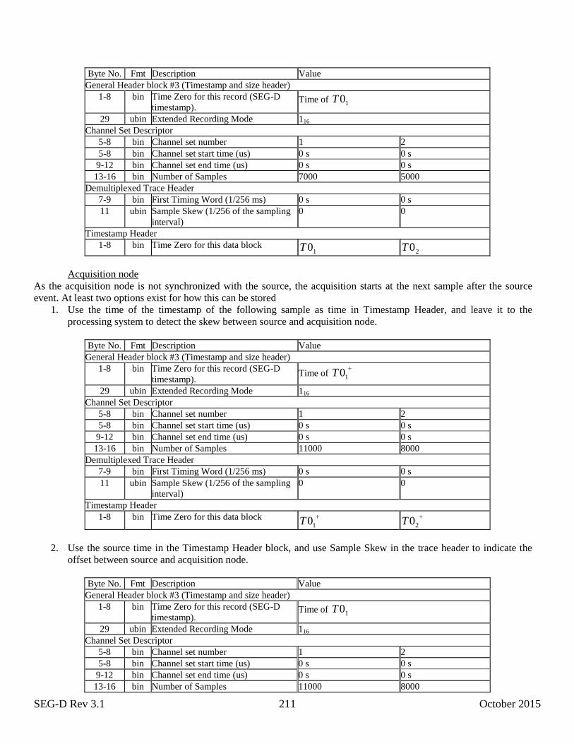
SEG-D Rev 3.1 211 October 2015
Byte No. Fmt Description Value
General Header block #3 (Timestamp and size header)
1-8 bin Time Zero for this record (SEG-D
timestamp). Time of 10T
29 ubin Extended Recording Mode 116
Channel Set Descriptor
5-8 bin Channel set number 1 2
5-8 bin Channel set start time (us) 0 s 0 s
9-12 bin Channel set end time (us) 0 s 0 s
13-16 bin Number of Samples 7000 5000
Demultiplexed Trace Header
7-9 bin First Timing Word (1/256 ms) 0 s 0 s
11 ubin Sample Skew (1/256 of the sampling
interval)
0 0
Timestamp Header
1-8 bin Time Zero for this data block 10T 20T
Acquisition node
As the acquisition node is not synchronized with the source, the acquisition starts at the next sample after the source
event. At least two options exist for how this can be stored
1. Use the time of the timestamp of the following sample as time in Timestamp Header, and leave it to the
processing system to detect the skew between source and acquisition node.
Byte No. Fmt Description Value
General Header block #3 (Timestamp and size header)
1-8 bin Time Zero for this record (SEG-D
timestamp). Time of
10T
29 ubin Extended Recording Mode 116
Channel Set Descriptor
5-8 bin Channel set number 1 2
5-8 bin Channel set start time (us) 0 s 0 s
9-12 bin Channel set end time (us) 0 s 0 s
13-16 bin Number of Samples 11000 8000
Demultiplexed Trace Header
7-9 bin First Timing Word (1/256 ms) 0 s 0 s
11 ubin Sample Skew (1/256 of the sampling
interval)
0 0
Timestamp Header
1-8 bin Time Zero for this data block
10T
20T
2. Use the source time in the Timestamp Header block, and use Sample Skew in the trace header to indicate the
offset between source and acquisition node.
Byte No. Fmt Description Value
General Header block #3 (Timestamp and size header)
1-8 bin Time Zero for this record (SEG-D
timestamp). Time of 10T
29 ubin Extended Recording Mode 116
Channel Set Descriptor
5-8 bin Channel set number 1 2
5-8 bin Channel set start time (us) 0 s 0 s
9-12 bin Channel set end time (us) 0 s 0 s
13-16 bin Number of Samples 11000 8000
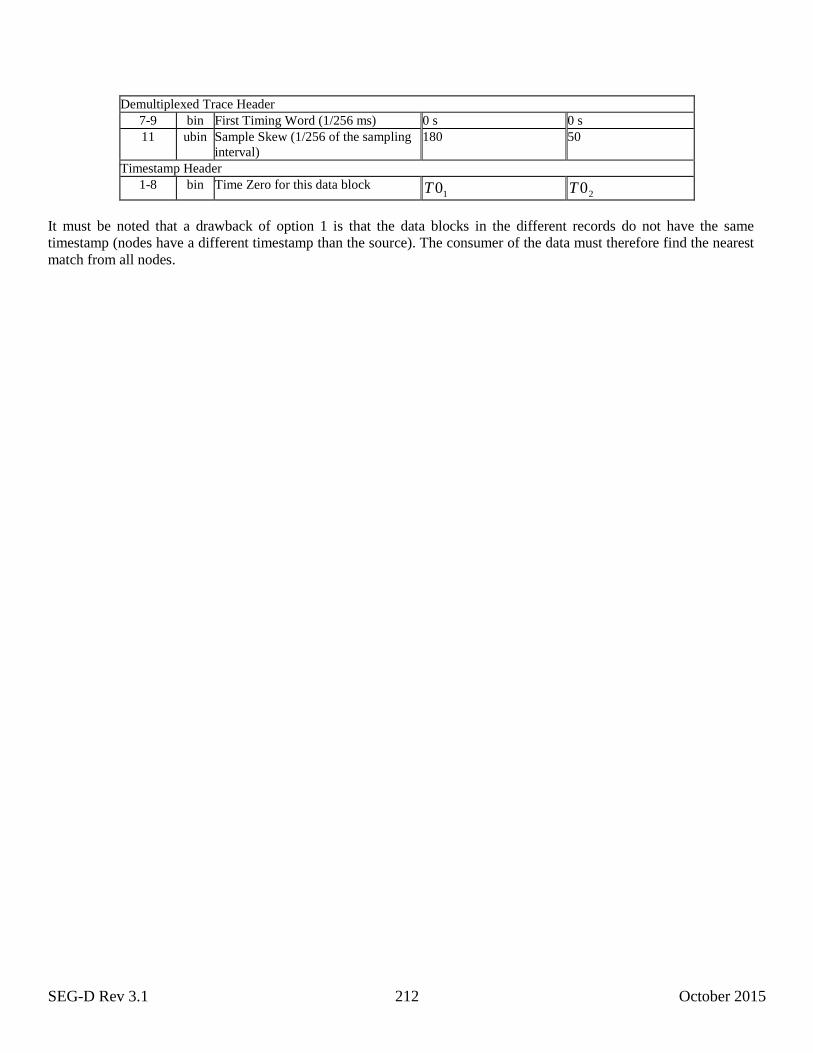
SEG-D Rev 3.1 212 October 2015
Demultiplexed Trace Header
7-9 bin First Timing Word (1/256 ms) 0 s 0 s
11 ubin Sample Skew (1/256 of the sampling
interval)
180 50
Timestamp Header
1-8 bin Time Zero for this data block 10T 20T
It must be noted that a drawback of option 1 is that the data blocks in the different records do not have the same
timestamp (nodes have a different timestamp than the source). The consumer of the data must therefore find the nearest
match from all nodes.

SEG-D Rev 3.1 213 October 2015
Appendix F: Unit of Measure Integer Codes
Unit of Measure Integer Codes used in the SEG-D Measurement block are assigned by Energistics, which maintains the
current list of codes.
To request a modification of the integer codes, contact:
Energistics
One Sugar Creek Center Blvd.
Suite 1075
Sugar Land, TX 77478 USA
+1 281 243-2121 telephone
+1 281 243-2132 fax
http://www.energistics.org/
The following is a snapshot of the Energistics Unit of Measure Integer Codes v 1.0 (done on 07-mar-2014). For an
updated list please refer to http://www.energistics.org/asset-data-management/unit-of-measure-standard.
The listing is an update of the v0.9 found in the June 2012 version of the SEG-D standard document. Some units/codes
have been deprecated (listed like this), and some have been added. Please do not use the deprecated codes.
Energistics Unit of Measure Integer Codes v1.0
Quantity Class Codes
Quantity Class Code (mass per time) per area 1001
(mass per time) per length 1002
(mass per volume) per length 1003
(mole per time) per area 1004
(volume per time) length 1005
(volume per time) per area 1006
(volume per time) per length 1007
(volume per time) per time 1008
(volume per time) per volume 1009
absorbed dose 1010
acceleration linear 1011
activity (of radioactivity) 1012
amount of substance 1013
angle per length 1014
angle per volume 1015
angular acceleration 1016
angular velocity 1017
area 1018
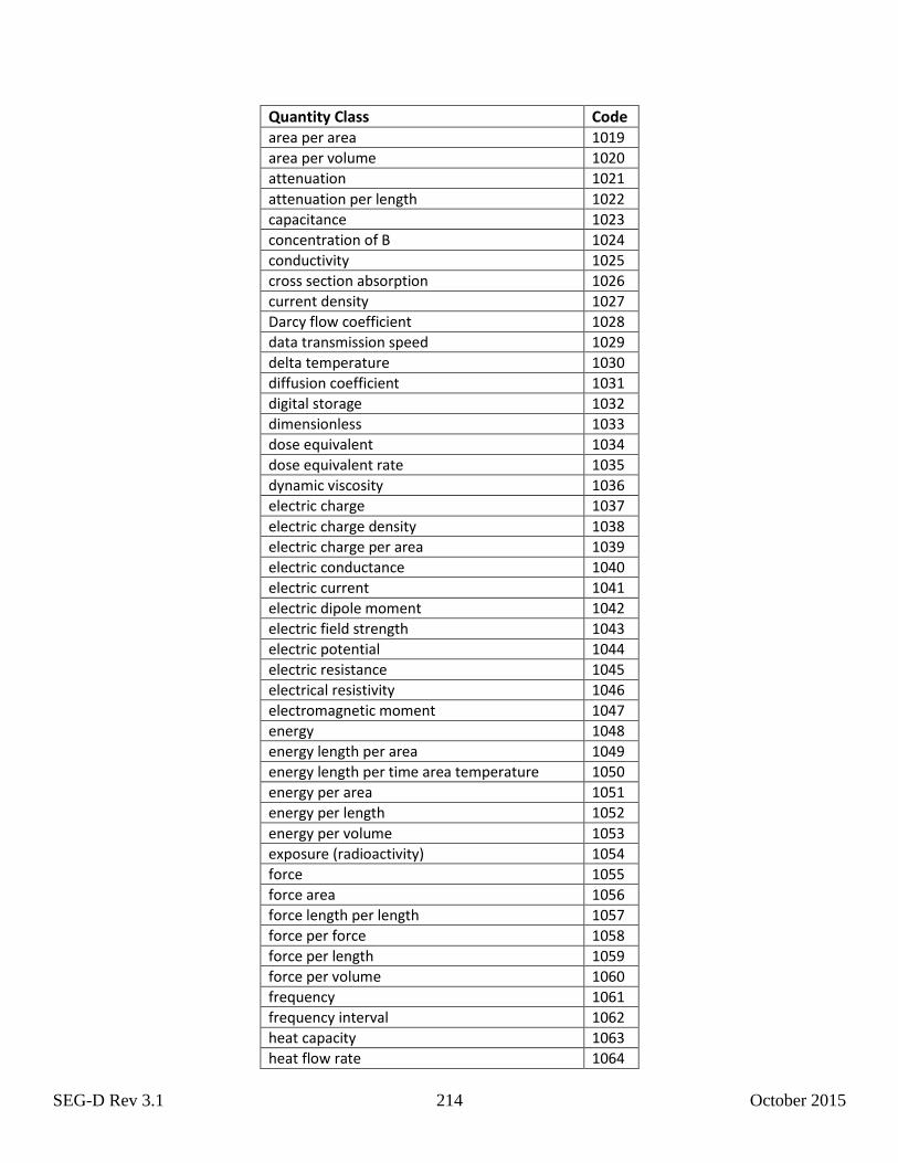
SEG-D Rev 3.1 214 October 2015
Quantity Class Code area per area 1019
area per volume 1020
attenuation 1021
attenuation per length 1022
capacitance 1023
concentration of B 1024
conductivity 1025
cross section absorption 1026
current density 1027
Darcy flow coefficient 1028
data transmission speed 1029
delta temperature 1030
diffusion coefficient 1031
digital storage 1032
dimensionless 1033
dose equivalent 1034
dose equivalent rate 1035
dynamic viscosity 1036
electric charge 1037
electric charge density 1038
electric charge per area 1039
electric conductance 1040
electric current 1041
electric dipole moment 1042
electric field strength 1043
electric potential 1044
electric resistance 1045
electrical resistivity 1046
electromagnetic moment 1047
energy 1048
energy length per area 1049
energy length per time area temperature 1050
energy per area 1051
energy per length 1052
energy per volume 1053
exposure (radioactivity) 1054
force 1055
force area 1056
force length per length 1057
force per force 1058
force per length 1059
force per volume 1060
frequency 1061
frequency interval 1062
heat capacity 1063
heat flow rate 1064
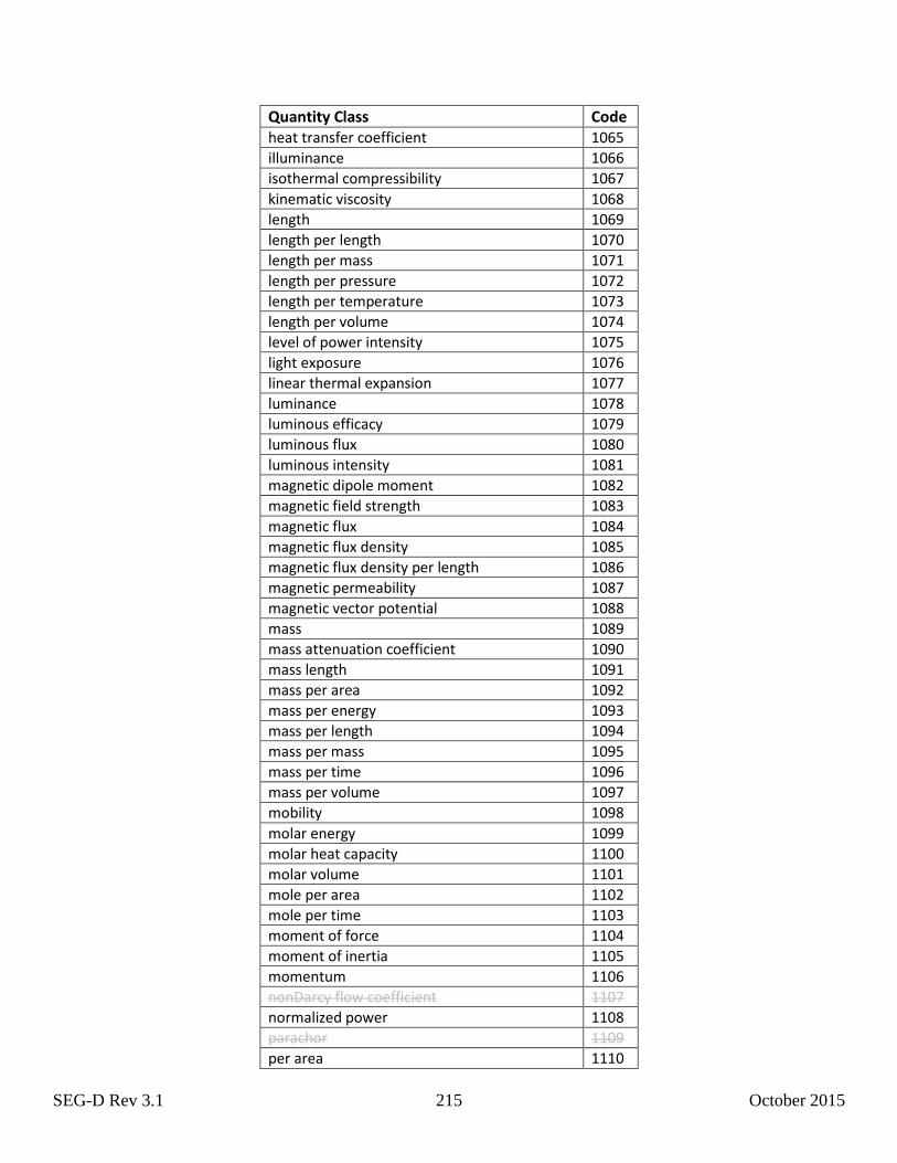
SEG-D Rev 3.1 215 October 2015
Quantity Class Code heat transfer coefficient 1065
illuminance 1066
isothermal compressibility 1067
kinematic viscosity 1068
length 1069
length per length 1070
length per mass 1071
length per pressure 1072
length per temperature 1073
length per volume 1074
level of power intensity 1075
light exposure 1076
linear thermal expansion 1077
luminance 1078
luminous efficacy 1079
luminous flux 1080
luminous intensity 1081
magnetic dipole moment 1082
magnetic field strength 1083
magnetic flux 1084
magnetic flux density 1085
magnetic flux density per length 1086
magnetic permeability 1087
magnetic vector potential 1088
mass 1089
mass attenuation coefficient 1090
mass length 1091
mass per area 1092
mass per energy 1093
mass per length 1094
mass per mass 1095
mass per time 1096
mass per volume 1097
mobility 1098
molar energy 1099
molar heat capacity 1100
molar volume 1101
mole per area 1102
mole per time 1103
moment of force 1104
moment of inertia 1105
momentum 1106
nonDarcy flow coefficient 1107
normalized power 1108
parachor 1109
per area 1110
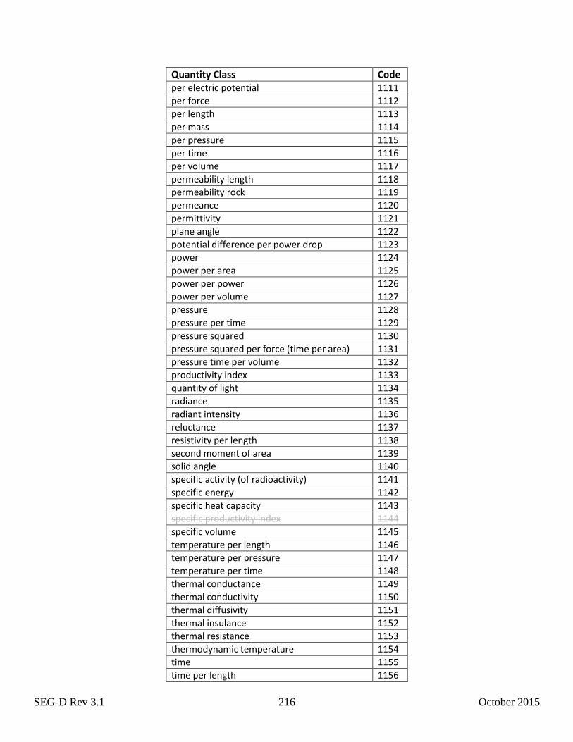
SEG-D Rev 3.1 216 October 2015
Quantity Class Code per electric potential 1111
per force 1112
per length 1113
per mass 1114
per pressure 1115
per time 1116
per volume 1117
permeability length 1118
permeability rock 1119
permeance 1120
permittivity 1121
plane angle 1122
potential difference per power drop 1123
power 1124
power per area 1125
power per power 1126
power per volume 1127
pressure 1128
pressure per time 1129
pressure squared 1130
pressure squared per force (time per area) 1131
pressure time per volume 1132
productivity index 1133
quantity of light 1134
radiance 1135
radiant intensity 1136
reluctance 1137
resistivity per length 1138
second moment of area 1139
solid angle 1140
specific activity (of radioactivity) 1141
specific energy 1142
specific heat capacity 1143
specific productivity index 1144
specific volume 1145
temperature per length 1146
temperature per pressure 1147
temperature per time 1148
thermal conductance 1149
thermal conductivity 1150
thermal diffusivity 1151
thermal insulance 1152
thermal resistance 1153
thermodynamic temperature 1154
time 1155
time per length 1156
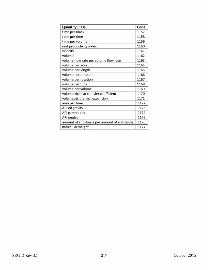
SEG-D Rev 3.1 217 October 2015
Quantity Class Code time per mass 1157
time per time 1158
time per volume 1159
unit productivity index 1160
velocity 1161
volume 1162
volume flow rate per volume flow rate 1163
volume per area 1164
volume per length 1165
volume per pressure 1166
volume per rotation 1167
volume per time 1168
volume per volume 1169
volumetric heat transfer coefficient 1170
volumetric thermal expansion 1171
area per time 1172
API oil gravity 1173
API gamma ray 1174
API neutron 1175
amount of substance per amount of substance 1176
molecular weight 1177
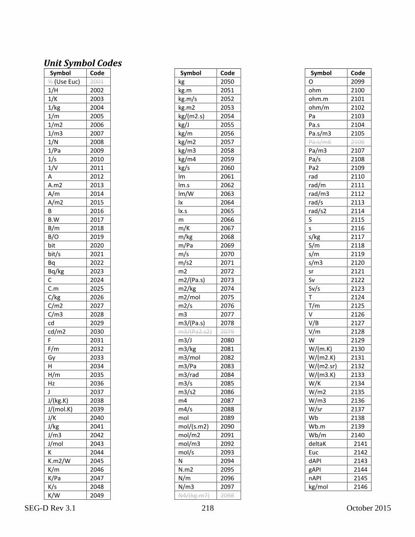
SEG-D Rev 3.1 218 October 2015
Unit Symbol Codes Symbol Code
% (Use Euc) 2001
1/H 2002
1/K 2003
1/kg 2004
1/m 2005
1/m2 2006
1/m3 2007
1/N 2008
1/Pa 2009
1/s 2010
1/V 2011
A 2012
A.m2 2013
A/m 2014
A/m2 2015
B 2016
B.W 2017
B/m 2018
B/O 2019
bit 2020
bit/s 2021
Bq 2022
Bq/kg 2023
C 2024
C.m 2025
C/kg 2026
C/m2 2027
C/m3 2028
cd 2029
cd/m2 2030
F 2031
F/m 2032
Gy 2033
H 2034
H/m 2035
Hz 2036
J 2037
J/(kg.K) 2038
J/(mol.K) 2039
J/K 2040
J/kg 2041
J/m3 2042
J/mol 2043
K 2044
K.m2/W 2045
K/m 2046
K/Pa 2047
K/s 2048
K/W 2049
Symbol Code
kg 2050
kg.m 2051
kg.m/s 2052
kg.m2 2053
kg/(m2.s) 2054
kg/J 2055
kg/m 2056
kg/m2 2057
kg/m3 2058
kg/m4 2059
kg/s 2060
lm 2061
lm.s 2062
lm/W 2063
lx 2064
lx.s 2065
m 2066
m/K 2067
m/kg 2068
m/Pa 2069
m/s 2070
m/s2 2071
m2 2072
m2/(Pa.s) 2073
m2/kg 2074
m2/mol 2075
m2/s 2076
m3 2077
m3/(Pa.s) 2078
m3/(Pa2.s2) 2079
m3/J 2080
m3/kg 2081
m3/mol 2082
m3/Pa 2083
m3/rad 2084
m3/s 2085
m3/s2 2086
m4 2087
m4/s 2088
mol 2089
mol/(s.m2) 2090
mol/m2 2091
mol/m3 2092
mol/s 2093
N 2094
N.m2 2095
N/m 2096
N/m3 2097
N4/(kg.m7) 2098
Symbol Code
O 2099
ohm 2100
ohm.m 2101
ohm/m 2102
Pa 2103
Pa.s 2104
Pa.s/m3 2105
Pa.s/m6 2106
Pa/m3 2107
Pa/s 2108
Pa2 2109
rad 2110
rad/m 2111
rad/m3 2112
rad/s 2113
rad/s2 2114
S 2115
s 2116
s/kg 2117
S/m 2118
s/m 2119
s/m3 2120
sr 2121
Sv 2122
Sv/s 2123
T 2124
T/m 2125
V 2126
V/B 2127
V/m 2128
W 2129
W/(m.K) 2130
W/(m2.K) 2131
W/(m2.sr) 2132
W/(m3.K) 2133
W/K 2134
W/m2 2135
W/m3 2136
W/sr 2137
Wb 2138
Wb.m 2139
Wb/m 2140
deltaK 2141
Euc 2142
dAPI 2143
gAPI 2144
nAPI 2145
kg/mol 2146