Embed Size (px)
Citation preview
SEG-D, Rev 2 SEG Field Tape Standards December, 1996
Minor revision status: January 2001 Revised manufacturers’ list. August 2004 Revised manufacturers’ list. January 2006 Revised manufacturers’ list.
ii
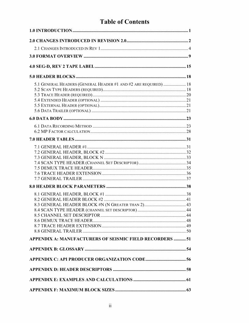
Table of Contents1.0 INTRODUCTION....................................................................................................... 1
2.0 CHANGES INTRODUCED IN REVISION 2.0....................................................... 2
2.1 CHANGES INTRODUCED IN REV 1.............................................................................. 4
3.0 FORMAT OVERVIEW ............................................................................................. 9
4.0 SEG-D, REV 2 TAPE LABEL ................................................................................. 15
5.0 HEADER BLOCKS .................................................................................................. 18
5.1 GENERAL HEADERS (GENERAL HEADER #1 AND #2 ARE REQUIRED) .................... 185.2 SCAN TYPE HEADERS (REQUIRED).......................................................................... 185.3 TRACE HEADER (REQUIRED)................................................................................... 205.4 EXTENDED HEADER (OPTIONAL) ............................................................................ 215.5 EXTERNAL HEADER (OPTIONAL)............................................................................. 215.6 DATA TRAILER (OPTIONAL) .................................................................................... 21
6.0 DATA BODY............................................................................................................. 23
6.1 DATA RECORDING METHOD ................................................................................... 236.2 MP FACTOR CALCULATION..................................................................................... 28
7.0 HEADER TABLES................................................................................................... 31
7.1 GENERAL HEADER #1........................................................................................ 317.2 GENERAL HEADER, BLOCK #2 ........................................................................ 327.3 GENERAL HEADER, BLOCK N ......................................................................... 337.4 SCAN TYPE HEADER (CHANNEL SET DESCRIPTOR).......................................... 347.5 DEMUX TRACE HEADER................................................................................... 357.6 TRACE HEADER EXTENSION........................................................................... 367.7 GENERAL TRAILER ............................................................................................ 37
8.0 HEADER BLOCK PARAMETERS ....................................................................... 38
8.1 GENERAL HEADER, BLOCK #1 ........................................................................ 388.2 GENERAL HEADER BLOCK #2 ......................................................................... 418.3 GENERAL HEADER BLOCK #N (N GREATER THAN 2)..................................... 438.4 SCAN TYPE HEADER (CHANNEL SET DESCRIPTOR) ........................................... 448.5 CHANNEL SET DESCRIPTOR............................................................................ 448.6 DEMUX TRACE HEADER................................................................................... 488.7 TRACE HEADER EXTENSION........................................................................... 498.8 GENERAL TRAILER ............................................................................................ 50
APPENDIX A: MANUFACTURERS OF SEISMIC FIELD RECORDERS ........... 51
APPENDIX B: GLOSSARY .......................................................................................... 54
APPENDIX C: API PRODUCER ORGANIZATION CODE.................................... 56
APPENDIX D: HEADER DESCRIPTORS ................................................................. 58
APPENDIX E: EXAMPLES AND CALCULATIONS ............................................... 61
APPENDIX F: MAXIMUM BLOCK SIZES ............................................................... 63
1
1.0 Introduction
At the SEG Convention in October 1995, the SEG Technical Standards committee voted to re-activatethe Field Tape Standards Subcommittee. The charter for the subcommittee, as stated in a letter fromMike Norris, Chairman of the SEG Technical Standards Committee: “As stated at the TechnicalStandards annual meeting, the purpose of the subcommittee is to review the SEG-D field tape standardwith respect to the emerging high density media. Specifically the subcommittee should review block sizerequirements to maximize throughput, recoverability and the use of standard labels. The subcommitteeshould also address any other outstanding SEG-D issues.”
Following the directive of the SEG Technical Standards Committee, the subcommittee prepared a newrevision to the SEG-D standard, to be called SEG-D, Rev 2. This new format will significantly improvethe efficiency of using high density media and will support the use of tapes with physical and electronicreadable labels.
The subcommittee consisted of the following individuals:
• George Wood Western Geophysical Chairman• Phil Behn Input/Output• Claes Borresen PGS• William Guyton Western Geophysical• Louis Miles Syntron• Dennis O‘Neill Geco-Prakla• Sut Oishi Shell• Tony Scales Sercel
Other active participants included: Cliff Ray (Fairfield), Bonnie Rippere (Shell), Martin Hlavaty (Shell),Don Funkhouser (Western), and Mike Norris (Western).
Since the use of high density media is expanding rapidly in the industry today, the Technical StandardsCommittee directed the Field Tape Subcommittee to develop an acceptable standard in the first half of1996. This target schedule led to a split of the committee effort towards this Rev 2 standard to solve theimmediate needs of the industry, and a longer term effort toward a next generation format.
The SEG has accepted the RODE format as a standard for data encapsulation. The Field Tape Standardscommittee has the responsibility to define the mapping of seismic acquisition data onto RODE. Thecommittee has spent some time reviewing the RODE format as a possible field tape format. But theflexibility and wide range of options in RODE have made it impossible for the committee to completelyevaluate whether it is possible to adopt a version of RODE as a field tape standard. The committee feelsthat the complete RODE format is too flexible to be suitable for field tape recording without somerestrictions. The committee will continue working toward an acceptable subset of RODE for field taperecording.
2
2.0 Changes Introduced in Revision 2.0
The following list discusses each of the specific changes made in Revision 2 compared to Revision 1.0.Also mentioned are changes which were discussed as potential changes to be included in Rev 2, but werenot included in Rev 2.
1. Since Rev 2 is intended to handle higher density tapes, acceptable media is expanded to include:3490/3490E, 3590, D2, and D3.
2. It is not anticipated that the higher density drives will be used to record multiplexed data. Rev 2does not support multiplexed data.
3. No specific changes will be made to SEG-D to handle “non-shot domain” data. Either a newcommittee should be formed, or the charter of this committee should be extended to develop anew format for this application. It does not appear practical to extend SEG-D to fit thisapplication.
4. No special arrangements will be made to provide a standard method of recording SPS in theSEG-D header. The relevant portions of SPS can be put into existing header extensions in userdefined positions.
5. The MP factor description will be modified to clarify the meaning for fixed bit data (see MPdiscussion in section 7).
6. The description of byte 12 in the General Header is being clarified to clearly state that the bytedefines the number of additional blocks. Figure 4 in the SEG-D Rev 1 document will be changedfrom # BLKS IN GEN HDR to “# Additional blks in Gen Hdr”. Another correction will be madeto correctly state, for byte 1 of the General Header, “File number of four digits (0-9999) set toFFFF (Hex) when the file number is greater than 9999.
7. The RECEIVER LINE NUMBER (bytes 1-3) and RECEIVER POINT NUMBER (Bytes 4-6) inthe Trace Header Extension have been modified to include a fractional component. An all one’spattern (FFFFFF Hex) in either of these fields, will serve as a flag to indicate that the completefive byte value will be located in newly defined locations in the Trace Header Extension. SeeTrace Header Extension table below.
8. The maximum number of Trace Header Extensions is now limited to 15.
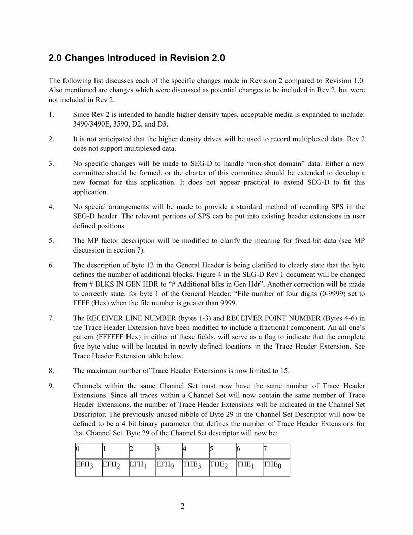
9. Channels within the same Channel Set must now have the same number of Trace HeaderExtensions. Since all traces within a Channel Set will now contain the same number of TraceHeader Extensions, the number of Trace Header Extensions will be indicated in the Channel SetDescriptor. The previously unused nibble of Byte 29 in the Channel Set Descriptor will now bedefined to be a 4 bit binary parameter that defines the number of Trace Header Extensions forthat Channel Set. Byte 29 of the Channel Set descriptor will now be:
0 1 2 3 4 5 6 7
EFH3 EFH2 EFH1 EFH0 THE3 THE2 THE1 THE0

3
As a result of this limitation the Trace Header Extension field in Byte 10 of the Trace Headerwill also be redefined as a 4 bit value limited to a maximum of 15 Trace Header Extensions.
10. The length of each trace within a Channel Set is now restricted to be the same value. Thislimitation and the restricting the number of Trace Header Extensions to the same number withina Channel Set will result in each trace within a Channel Set being recorded with the samenumber of bytes.
11. A tape label will be required on each tape. The details of this label format are described insection 4.
12. Data may be recorded in large logical blocks to maximize the transfer rates with high densitytape systems. 3 types of device structures are supported:
A) Variable block length devices.
Every shot record must be aligned on a block boundary (i.e. each block will contain data fromonly one shot record). Multiple channel sets may be included in each block. When the data to berecorded in a block contains less than the maximum number of bytes in the block, there will beno padding characters to fill the block.
Storage Unit Structure in field 3 in Storage Unit Label must contain the text “RECORD”
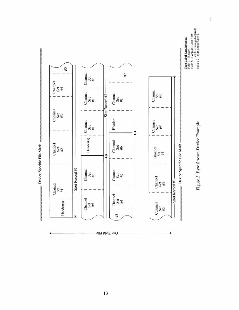
B) Byte stream devices
There is no concept of a block, even though there is a hidden underlying physical block structure.Within each file, one or more shot records are written consecutively without any gap.
Storage Unit Structure in field 3 in Storage Unit Label must contain the text “RECORD”
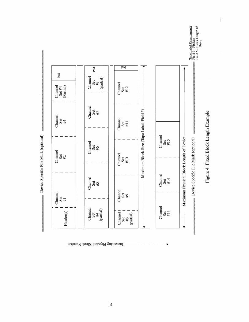
C) Fixed block length devices
Every shot record must be aligned on a block boundary (i.e. each block will contain data fromonly one shot record). Multiple channel sets may be included in each block. Typically the lastblock in a shot record will contain less data than the block size, the remaining part of this blockwill be padded with characters without any information.
Storage Unit Structure in field 3 in Storage Unit Label must contain the text “FIXREC” and theblock size is found in field 5 in Storage Unit Label.
Note: Structure A can be mapped to a file directly but one can not re-generate the sameinterblock gaps and File Marks from data stored on a file. Structure B and C can be mapped to afile directly and the structure can be re-generated apart from the original position of the FileMarks.
13. An appendix will be added to indicate the maximum allowable block size for accepted types ofmedia. It is expected that this table will need to be updated approximately once per year.
14. Byte 12 of the Trace Header will have an additional option, TR= 03 Trace has been edited. Thisparameter will indicate the acquisition system has modified one or more samples of this trace.During data acquisition, if a telemetry error occurs, a sample may be corrupted. Some radioacquisition systems fill in this missing data with a copy of the previous sample, or interpolate tofill in the missing sample. Trace edit can also occur when a noise edit process is applied by theacquisition system. The TR=03 flag should be set for those traces which have been modified bythe acquisition system.

4
15. The SEG-D, Rev 2 format treats data going to tape as a byte stream. File Marks are not requiredto separate shot records, however File Marks may be included in between shot records whereappropriate to ease error recovery and/or to provide logical partitioning of the data. If used, FileMarks may only be recorded at shot record boundaries. For field tapes, File Marks should bewritten as frequently as possible, preferably for every shot. If data is staged on disk, many shotscan be stored in each file. When SEG-D, Rev 2 data is recorded on tape, an EOD mark must berecorded after the last valid record and prior to the end of tape
16. The time standard referenced by byte 14 of the General Header has been changed from GMT toUTC.
17. Partitioning of a tape or other type media volume is now allowed. Each partition, or each tape ifnot partitioned, constitutes one storage unit. The storage unit label shall consist of the first 128bytes of the first user-writable tape record in the first user-writable physical block and may,optionally, be followed by an File Mark. No File Mark shall be written before the storage unitlabel.
18. Added a field in the Trace Header extension to indicate the type of sensor used for that trace(Byte 21).
2.1 Changes Introduced in Rev 1
In 1994, several changes were introduced to SEG-D to increase flexibility. These changes are listedbelow.
1. To allow for additional defined fields in SEG-D headers, additional blocks are allowed for theGeneral Header and Demux Trace Header.
2. Added provision for an optional set of General Trailer blocks. This type header allows provisionsfor recording auxiliary seismic system and real-time navigation related data in the trailer. Thetrailer is optional and typically follows all other recorded data.
The addition of the trailer will allow the accumulation of system faults, data QC information, real-time navigation position, and timing information on the same tape, and contiguous with, theshotpoint that it relates to. By recording this data after all of the other data, additional time isprovided for collecting the data and transferring it to the recording system.
The Trailer blocks take the same general form as the Channel Set Descriptor. Byte 11 uses the"Channel Type Identification" set to 1100 to indicate a Trailer block. Bytes 1 and 2 indicate thenumber of the General Trailer block, with the first block numbered as 1.
All other information in the trailer is optional and may be formatted as desired by themanufacturer/user.
The number of General Trailer blocks is indicated in bytes 13 and 14 of General Header Block #2.
3. Provide provision to include the revision of SEG-D format . Added to Bytes 11 and 12 of GeneralHeader Block #2 contain the SEG-D Revision Number. The revision number is a 16 bit unsignedbinary number. The Revision number is 1 for the proposed version.
In addition, in the General Header Block #1, nibble 1 of byte 12 contains the number of additionalblocks in the general header. Nibble 1, byte 12 is an unsigned binary number. This number will be1 or greater for SEG D Rev 1.

5
4. Added provision to include the source and receiver locations for each source and receiver location.Source locations are included in the General Header Blocks. Block #3 contains the position forSource Set #1. Additional General Header Blocks may be included to allow for additional SourceSets.
Source positions are defined by a Source Line Number (three bytes integer and two bytes fraction),a Source Point Number (three bytes integer and two bytes fraction), and a Source Point Index (onebyte). This index allows several locations for the source in the grid, the original value is 1 and thatvalue is incremented by 1 every time the source is moved, even when it is moved back to a previouslocation).
Receiver locations are included in Trace Header Extensions to be used with Demux Trace Headers.Receiver positions are defined by a Receiver Line Number (three integer bytes and two fractionbytes), a Receiver Point Number (three bytes integer and two bytes fraction), and a Receiver PointIndex (one byte). This index allows for defining the receiver group in the grid, the original value is1 and that value is incremented by 1 every time the receiver is moved, even when it is moved backto the previous location.
5. Provide for the use of File Numbers greater than 9999. Bytes 1,2, and 3 in General Header Block#2 allow for a three byte, binary file number. When the file number is greater than 9999, bytes 1and 2 in the General Header Block #1 must be set to FFFF.
6. Provide for Extended Channel Sets/Scan Types. General Header Block #2 allows for a two byte,binary number of Channel Sets/Scan Types in bytes 4 and 5. When using the Extended ChannelSets/Scan Types, byte 29 of General Header #1 must be set to FF.
7. Provide for additional Extended and External Header blocks. General Header Block #2 bytes 6 and7 (for Extended Header blocks) and Bytes 8 and 9 (for External Header blocks) allow the use of atwo byte, binary number to allow more than 99 blocks. When using the these capabilities, GeneralHeader Block #1 byte 31 (for extended) and byte 32 (for external) must be set to FF.
8. Provide a mechanism for recording additional information about vibrator sources. Byte 15 of theGeneral Header Block #N indicates the signal used to control vibrator phase. Byte 16 indicates thetype of vibrator (P, Shear, Marine). Bytes 28 and 29 contain the phase angle between the pilot andthe phase feedback signal.
The additional vibrator information may be recorded for multiple sets of sources by using additionalGeneral Header blocks.
9. Provide for larger number of samples per trace. Using bytes 8, 9, and 10 of the Trace HeaderExtension.
10. Provide provisions for using 1/2" square tape cartridges. ( ANSI X3.180 1989).
11. Allow recording data in IEEE and other new formats.Additional Valid Format Codes for bytes 3 & 4 of the General Header are:

6
0036 24 bit 2's compliment integer multiplexed0038 32 bit 2's compliment integer multiplexed0058 32 bit IEEE multiplexed8036 24 bit 2's compliment integer demultiplexed8038 32 bit 2's compliment integer demultiplexed8058 32 bit IEEE demultiplexed
The IEEE format is fully documented in the IEEE standard, "ANSI/IEEE Std 754 - l985", available from the IEEE.
The IEEE format is summarized as follows:Bit 0 1 2 3 4 5 6 7Byte 1 S C7 C6 C5 C4 C3 C2 C1
Byte 2 C0 Q-1 Q-2 Q-3 Q-4 Q-5 Q-6 Q-7
Byte 3 Q-8 Q-9 Q-10 Q-11 Q-12 Q-13 Q-14 Q-15
Byte 4 Q-16 Q-17 Q-18 Q-19 Q-20 Q-21 Q-22 Q-23 (see Note 1)
The value (v) of a floating-point number represented in this format is determined as follows:
if e = 255 & f ¹ 0. .v = NaN Not-a-Number (see Note 2)if e = 255 & f = 0. .v = (-1)s *∞ Overflowif 0 < e < 255. . . .v = (-1)s *2e-127 *(1.f) Normalizedif e = 0 & f ¹ 0. . .v = (-1)s *2e-126 *(0.f) Denormalizedif e = 0 & f = O. . .v = (-1)s *0 ± zero
where e = binary value of all C's (exponent) f = binary value of all Q's (fraction)
NOTES: 1. Bit 7 of byte 4 must be zero to guarantee uniqueness of the start of scan in theMultiplexed format (0058). It may be non zero in the demultiplexed format(8058).
2. A Not-a-Number (NaN) is interpreted as an invalid number. All other numbersare valid and interpreted as described above.
12. Allow for the use of blocked records. Allow blocked demultiplexed data (integral number oftraces in a block). Headers will not be blocked. All records in a block will be the same size. Notall blocks will be the same size. Byte 20 in the general header (B1 = 1) will indicate blockeddata. Blocks will be limited to 128 kilobytes. All traces in a block are in the same Channel Set.
13. Added the effective stack order (unsigned binary), in byte 30 in the Channel Set descriptor. Setto 0 if the trace data was intentionally set to real 0. Set to 1 if no stack. Set to the effective stackorder if the data is the result of stacked data (with or without processing).
14. Improved definition of undefined fields. All undefined fields will be specified as: "This field isundefined by this format".
15. Added provisions for a Trace Edit byte (byte 10 of Demux Trace Header) to indicate traceszeroed for roll-on or roll-off and to indicate deliberately zeroed traces.
7
TR=0 No edit of this trace,TR=1 Trace part of dead channels for roll-on or roll-off spread; trace intentionally
zeroed.TR=2 Trace intentionally zeroed.
16. Increased precision of MP factor, using byte 7 of the Channel Set descriptor.
17. Since modern seismic vessels record more than one streamer at a time, a standard convention isrequired to identify which streamer recorded each channel of data. The Channel Set Descriptorsare updated to handle this task. The definition of a channel set is expanded to include thefollowing rules. A channel set is a group of channels that:
a) Use identical recording parameters. This includes the same record length and sampleinterval.
b) Use identical processing parameters, including the same filter selection and arrayforming parameters. A field has been added to Channel Set Descriptor byte 32 todescribe any array forming applied to data in that channel set.
c) Originates from the same streamer cable for marine data. The streamer cable numberfor each channel set has been added to Channel Set Descriptor byte 31.
d) Consists of channels with the same group spacing. For example, if one steamer hasshort group spacing close to the boat and longer groups spacing at long offsets, the datafrom that streamer would be recorded as two channel sets.
In addition, the first channel in each channel set will start with Trace number one.
18. Correct the MP factor calculation (refer to Appendix E7 in the SEG-D recording formatdescription.
MP CALCULATIONThe calculation of MP for a data recording method is given by one of the following equations:(1) MP = FS - PA - Cmax; for binary exponents,
(2) MP = FS - PA - 2 x Cmax; for quaternary exponents,
(3) MP = FS - PA - 4 x Cmax; for hexadecimal exponents (except the 4 byte excess 64method),
(4) MP = FS - PA - 4 (Cmax - 64); for excess 64 hexadecimal exponents and for 4 byteIEEE exponents,
where2FS = Converter full scale (millivolts),
2PA = Minimum system gain,
andCmax = maximum value of the data exponent,Cmax = 15 for binary exponents,
7 for quaternary exponents,3 for hexadecimal exponents except excess 64; and64 for excess 64 exponents and for 4 byte IEEE exponents.

8
19. Added the option for using record lengths in millisecond increments (rather than the previous0.5 second increments). The Extended Record Length is the record length, in unsigned binarymilliseconds, and is recorded in bytes 15-17 in General Header Block #2. If this option is used,Record Length (R), in the General Header Block #1, bytes 26, 27 must be set to FFF.

9
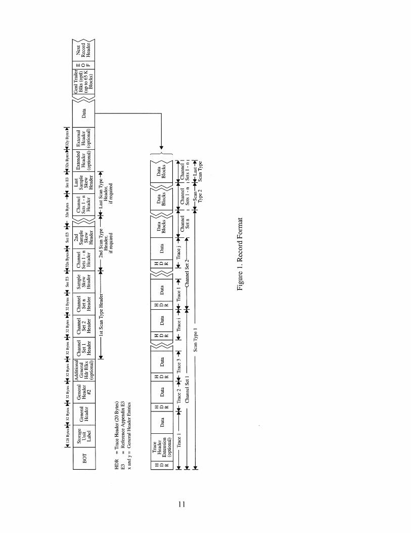
3.0 Format Overview
The SEG-D, Rev 2 format treats data going to tape as a byte stream. Figure 1 illustrates a typical recordstructure.
A tape, or other media to be used for SEG-D, Rev 2 recording may be partitioned. Each partition, oreach tape if not partitioned, constitutes one storage unit. The storage unit label shall consist of the first128 bytes of the first user-writable tape record in the first user-writable physical block and may,optionally, be followed by an File Mark. No File Mark shall be written before the storage unit label.
Each SEG-D Rev 2 tape must begin with a tape label, as detailed in section 4. Following the tape label,each seismic record is recorded in demultiplexed format. SEG-D, Rev 2 does not support multiplexeddata records.
When blocked data is being recorded, all of the headers may be included in the same block with theinitial channel set. Each channel set may be split across block boundaries. Block boundaries may notoccur within a trace.
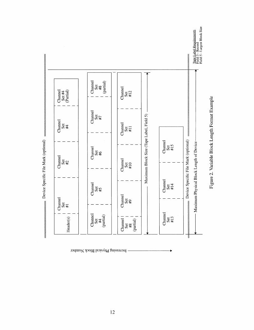
Data may be recorded in large blocks to maximize the transfer rates with high density tape systems. 3types of device structures are supported:
A) Variable block length devices.
Every shot record must be aligned on a block boundary (i.e. each block will contain data fromonly one shot record). Multiple channel sets may be included in each block. When the data to berecorded in a block contains less than the maximum number of bytes in the block, there will beno padding characters to fill the block.
Storage Unit Structure in field 3 in Storage Unit Label must contain the text “RECORD”
B) Byte stream devices
There is no concept of a block, even though there is a hidden underlying physical block structure.Within each file, one or more shot records are written consecutively without any gap.
Storage Unit Structure in field 3 in Storage Unit Label must contain the text “RECORD”
C) Fixed block length devices
Every shot record must be aligned on a block boundary (i.e. each block will contain data fromonly one shot record). Multiple channel sets may be included in each block. Typically the lastblock in a shot record will contain less data than the block size, the remaining part of this blockwill be padded with characters without any information.
Storage Unit Structure in field 3 in Storage Unit Label must contain the text “FIXREC” and theblock size is found in field 5 in Storage Unit Label.
Note: Structure A can be mapped to a file directly but one can not re-generate the sameinterblock gaps (if present) and File Marks from data stored on a file. Structure B and C can bemapped to a file directly and the structure can be re-generated apart from the original position ofthe File Marks.
The SEG-D, Rev 2 format treats data going to tape as a byte stream. File Marks are not required toseparate shot records, however File Marks may be included in between shot records where appropriate toease error recovery and/or to provide logical partitioning of the data. If used, File Marks may only be

10
recorded at shot record boundaries. For field tapes, File Marks should be written as frequently aspossible, preferably for every shot. If data is staged on disk, many shots can be stored in each file. WhenSEG-D, Rev 2 data is recorded on tape, an EOD mark must be recorded after that last valid record andprior to the end of tape.
If the tape media supports multiple partitions, SEG-D data may be written to any of the partitions of thetape, each beginning with a Storage Unit Label. Data from one partition can not “run-over” into asubsequent partition, each partition must be capable of being decoded in isolation.
On one tape, it is allowed to mix partitions containing SEG-D data with partitions containing non SEG-Dformatted information.
11
12
13
14
15
4.0 SEG-D, Rev 2 Tape Label
The first 128 bytes of data on a Rev 2 tape must consist of ASCII characters and will constitute a storageunit label. This label is very similar to the RP-66 storage unit label. The label format is summarized inthe table below.
If the tape media supports multiple partitions, SEG-D data may be written to any of the partitions of thetape, each beginning with a Storage Unit Label. Data from one partition can not “run-over” into asubsequent partition, each partition must be capable of being decoded in isolation.
On one tape, it is allowed to mix partitions containing SEG-D data with partitions containing non SEG-Dformatted information.
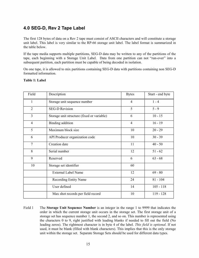
Table 1: Label
Field Description Bytes Start - end byte
1 Storage unit sequence number 4 1 - 4
2 SEG-D Revision 5 5 - 9
3 Storage unit structure (fixed or variable) 6 10 - 15
4 Binding addition 4 16 - 19
5 Maximum block size 10 20 - 29
6 API Producer organization code 10 30 - 39
7 Creation date 11 40 - 50
8 Serial number 12 51 - 62
9 Reserved 6 63 - 68
10 Storage set identifier 60
External Label Name 12 69 - 80
Recording Entity Name 24 81 - 104
User defined 14 105 - 118
Max shot records per field record 10 119 - 128
Field 1 The Storage Unit Sequence Number is an integer in the range 1 to 9999 that indicates theorder in which the current storage unit occurs in the storage set. The first storage unit of astorage set has sequence number 1, the second 2, and so on. This number is represented usingthe characters 0 to 9, right justified with leading blanks if needed to fill out the field (Noleading zeros). The rightmost character is in byte 4 of the label. This field is optional. If notused, it must be blank (filled with blank characters). This implies that this is the only storageunit within the storage set. Separate Storage Sets should be used for different data types.
16
Field 2 The SEG-D Revision field indicates which revision of SEG-D was used to record the data onthis tape. SD2.0 indicates that the data was recorded using SEG-D, Revision 2.0. This field isrequired.
Field 3 Storage Unit Structure is a name indicating the record structure of the storage unit. Thisname is left justified with trailing blanks if needed to fill out the field. The leftmost characteris in byte 10 of the label. For SEG-D, Rev 2 tapes, this field must contain “RECORD” or“FIXREC”. This field is required.
“RECORD” -- Records may be of variable length, ranging up to the Blocksize lengthspecified in the maximum Block size field of the storage unit label (if not zero). If themaximum Block size specified is zero, then records may be of any length.
“FIXREC” -- All records in the storage unit have the same length, namely that specified in themaximum Block size field of the storage unit label. Although all storage units in the samestorage set must have a FIXREC structure, the maximum record length may be different indifferent storage units. When the FIXREC option is used, then the maximum record lengthfield shall not be 0 (zero).
Field 4 Binding edition is the character B in byte 16 of the label followed by a positive integer in therange 1 to 999 (no leading zeros), left justified with trailing blanks if needed to fill out thefield. The integer value corresponds to the edition of the Part 3 of the API, RP66 standardused to describe the physical binding of the logical format to the storage unit. This field isrequired.
Field 5 Maximum Block Size is an integer in the range of 0 to 4,294,967,295 (232-1), indicating themaximum block length for the storage unit, or 0 (zero) if undeclared. This number isrepresented using the characters 0 to 9, right justified, with leading blanks if necessary to fillout the field (no leading zeros). The rightmost character is byte 29 of the label. A valid valueor 0 (zero) must be recorded.
Field 6 Producer organization code is an integer in the range of 0 to 4,294,967,295 (232-1)indicating the organization code of the storage unit producer. This number is representedusing the characters 0 to 9, right justified, with leading blanks if necessary to fill out the field(NO leading zeros). The rightmost character is byte 39 of the label. This field is required.
Organization codes are assigned by API Exploration and Production Department, whichmaintains the current list of codes. To request a new organization code, contact:
American Petroleum InstituteExploration & Production Department700 North Pearl Street, Suite 1840 (LB382)Dallas, Texas 75201-2845Phone: 214-953-1101 or 720-5712; Fax 214-748-7962
A copy of the most recent list is included in Appendix C.
Field 7 Creation date is the earliest date that any current information was recorded on the storageunit. The date is represented in the form dd-MMM-yyyy, where yyyy is the year (e.g. 1996),MMM is one of (JAN, FEB, MAR, APR, MAY, JUN, JUL, AUG, SEP, OCT, NOV, DEC),and dd is the day of the month in the range 1 to 31. Days 1 to 9 may have one leading blank.The separator is a hyphen (code 4510). This field is required.
Field 8 Serial number is an ID used to distinguish the storage unit from other storage units in anarchive of an enterprise. The specification and management of serial numbers is delegated toorganizations using this standard. If an external label is used the name/number must be a
17
subset of the serial number or the External Label Name in Field 10, and must occupy therightmost characters in the serial number (or External Label Name). This field is required.
Field 9 This field is reserved and should be recorded as all blanks (code 3210).
Field 10 The Storage set identifier is a descriptive name for the storage set. Every storage unit in thesame storage set shall have the same value for the user defined portion of the storage setidentifier in its storage unit label. Included in the Storage Set Identifier is the ExternalLabel Name. The characters in this field are right justified with leading blank characters asrequired. If the tape does not have a physical label, then this field must be blank. A physicallabel is optional, but if it exists, then this field is required only if the external label is differentfrom the lower 6 characters of the Serial Number in field 8. The next field in the Storage setidentifier is the Recording Entity Name. This must contain the crew number or name, orsome other unique identifier which will differentiate the recording entity which recorded thisdata from any other recording entity within the organization (as included in field 6). The 24bytes may by any alphanumeric characters. If multiple recording systems are used on a vesselor crew, then data recorded on each system must be clearly distinguished. For example, anABC Geophysical crew (party 13), on the M/V Gopher, recording data on two Zip 6000recording systems might have a Recording Entity Name on tapes recording on the firstrecording system of:
ABC, Gopher, P13, Zip#1
On the second system, the Recording Entity Name might be:
ABC, Gopher, P13, Zip#2
The Recording Entity Name field is required.
USER DEFINED
The next 14 bytes in this field may contain any other user input information. The only restrictionis that the data must be in ASCII.
Max Number of shot records per field record. Field Records are data between File Marks (10bytes).
It is not acceptable to use an ANSI label (or any other label or data) prior to the Storage UnitLabel.
An external, physical label is not required.

18
5.0 Header blocks
The headers are blocks of data prior to the seismic data, which contain auxiliary information about theseismic data, the acquisition parameters, acquisition geometry, plus user defined information. The headerblock includes at least two General Headers, one or more Scan Type headers, and optional Extended andExternal headers. Trace Headers are included in conjunction with each seismic data trace. Sections 7 and8 include detailed information about the content of each type header.
In addition to header blocks which are recorded prior to the seismic data traces, an optional GeneralTrailer is allowed following the seismic data. This allows recording other auxiliary information which isnot available at the beginning of the record. Sections 7 & 8 include detailed description of the allowedfields of the General Trailer.
5.1 General Headers (General Header #1 and #2 are required)
General Header #1 is 32 bytes long and contains information similar to SEG A, B, C, and the originalSEG-D headers. Abbreviations are as close as possible to those used in previous formats.
SEG-D, Rev 2 requires the use of General Header #1 and General Header #2 (as was also required inSEG-D, Rev 1). General Header #2 provides locations to record the source location, and otherparameters, for each record. Source positions are defined by a source line number (three bytes integerand two bytes fraction), a source point number (three bytes integer and two bytes fraction), and a sourcepoint index (one byte). This index allows several locations for the source in the grid, the original value is1 and that value is incremented by 1 every time the source is moved, even when it is moved back to aprevious location. More General header block extensions may be added to record parameters foradditional sources.
General Header blocks #3 (optional) and higher provide locations to record information about vibratorsources. Byte 15 of the general header block #N (N>2) indicates the signal used to control vibrator phase.Byte 16 indicates the type of vibrator. Bytes 28 and 29 contain the phase angle between the pilot and thephase feedback signal.
Bytes 1,2,3 in general header block #2 allow for a three byte, binary file number. When the file number isgreater than 9999, bytes 1 and 2 in the general header block #1 must be set to FFFF.
General header block #2 also allows for a two byte, binary number of channel sets/scan types in bytes 4and 5. When using the extended channel sets/scan types, byte 29 of the general header #1 must be set toFF.
Additional blocks may be added as needed by the manufacturer or user.
5.2 Scan Type Headers (required)
The Scan Type header is used to describe the information of the recorded channels (filters, sampleintervals, sample skew, etc.). The Scan Type header is composed of one or more channel set descriptorsfollowed by skew information. The channel set descriptors must appear in the same order as theirrespective channel sets will appear within a base scan interval. A channel set, which is part of a scantype, is defined as a group of channels all recorded with identical recording parameters. One or morechannel sets can be recorded concurrently within one scan type. In addition, there can be multiple scantypes to permit dynamic scan type changes during the record (e.g., 12 channels at 1/2 ms switched atabout 1 second to 48 channels at 2 ms). Where there are dynamic changes, scan type header 1 describes

19
the first part of the record, scan type header 2 the second part, etc. Within the scan type header, eachchannel set descriptor is composed of a 32 byte field, and up to 99 channel set descriptors may bepresent. In addition, up to 99 scan type headers may be utilized in a record.
Following the channel set descriptors of a scan type are a number of 32 byte fields (SK, specified in byte30 of the general header #1) that specify sample skew. Sample skew (SS) is recorded in a single byte foreach sample of each subscan of each channel set, in the same order as the samples are recorded in thescan. Each byte represents a fractional part of the base scan interval (Byte 23 of general header #1). Theresolution is 1/256 of this interval. For instance, if the base scan interval is 2 msec, the least significantbit in the sample skew byte is 1/256 of 2 msec or 7.8125 microseconds.
A channel set is a group of channels that:a) Use identical recording parameters. This includes the same record length and sample interval.b) Use identical processing parameters, including the same filter selection and array forming
parameters.c) Originates from the same streamer cable for marine data. The streamer cable number for each
channel set is included in the channel set descriptor byte 31.d) Consists of channels with the same group spacing. For example, if one streamer has short group
spacing close to the boat and longer group spacing at long offsets, the data from the streamer wouldbe recorded as two channel sets. The first channel in each channel set will start with trace numberone.
The following is a list of ground rules for the scan type header:
1. The order in which channel sets are described in the header will be the same as the order in whichthe data are recorded for each channel set.
2. In a scan type header containing multiple channel set descriptors with different sample intervals,each channel set descriptor will appear only once in each scan type header. Within the data block,however, shorter sampling interval data are recorded more frequently.
3. In the case of multiple scan type records, such as the dynamically switched sampling interval case,each scan type will contain the same number of channel sets. Any unused channel sets needed in ascan type must be so indicated by setting bytes 9 and 10 (channels per channel set) to zero in thechannel set descriptor.
4. In multiple scan type records, the number of bytes per base scan interval must remain a constant forall scan types recorded.
5. Channel set order within a scan type should be: auxiliary channels, long sampling intervalchannels, short sampling interval channels. All channel sets of the same sampling interval shouldbe contiguous.
6. Channels within the same Channel Set must now have the same number of Trace HeaderExtensions. Since all traces within a Channel Set will contain the same number of Trace HeaderExtensions, the number of Trace Header Extensions will be indicated in the Channel SetDescriptor. The previously unused nibble of Byte 29 in the Channel Set Descriptor will now bedefined to be a 4 bit binary parameter that defines the number of Trace Header Extensions for thatChannel Set. Byte 29 of the Channel Set descriptor will now be:
0 1 2 3 4 5 6 7
EFH3 EFH2 EFH1 EFH0 THE3 THE2 THE1 THE0
20
As a result of this limitation the Trace Header Extension field in Byte 11 of the Trace Header is alsoredefined as a 4 bit value limited to a maximum of 15 Trace Header Extensions.
7. The length of each trace within a Channel Set is restricted to be the same value. This limitation andthe restricting the number of Trace Header Extensions to the same number within a Channel Set willresult in each trace within a Channel Set being recorded with the same number of bytes.
5.3 Trace Header (required)
The trace header length is 20 bytes and is an identifier that precedes each channel’s data. The traceheader and the trace data are recorded as one block of data. A trace is restricted to one channel of datafrom one channel set of one scan type. Some of the information in the trace header is taken directly fromthe general header and the scan type header.
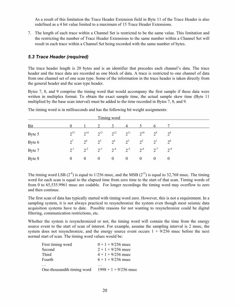
Bytes 7, 8, and 9 comprise the timing word that would accompany the first sample if these data werewritten in multiplex format. To obtain the exact sample time, the actual sample skew time (Byte 11multiplied by the base scan interval) must be added to the time recorded in Bytes 7, 8, and 9.
The timing word is in milliseconds and has the following bit weight assignments:
Timing word
Bit 0 1 2 3 4 5 6 7
Byte 5 215 214 213 212 211 210 29 28
Byte 6 27 26 25 24 23 22 21 20
Byte 7 2-1 2-2 2-3 2-4 2-5 2-6 2-7 2-8
Byte 8 0 0 0 0 0 0 0 0
The timing word LSB (2-8) is equal to 1/256 msec, and the MSB (215) is equal to 32,768 msec. The timingword for each scan is equal to the elapsed time from zero time to the start of that scan. Timing words offrom 0 to 65,535.9961 msec are codable. For longer recordings the timing word may overflow to zeroand then continue.
The first scan of data has typically started with timing word zero. However, this is not a requirement. In asampling system, it is not always practical to resynchronize the system even though most seismic dataacquisition systems have to date. Possible reasons for not wanting to resynchronize could be digitalfiltering, communication restrictions, etc.
Whether the system is resynchronized or not, the timing word will contain the time from the energysource event to the start of scan of interest. For example, assume the sampling interval is 2 msec, thesystem does not resynchronize, and the energy source event occurs 1 + 9/256 msec before the nextnormal start of scan. The timing word values would be:
First timing word 0 + 1 + 9/256 msecSecond 2 + 1 + 9/256 msecThird 4 + 1 + 9/256 msecFourth 6 + 1 + 9/256 msec… …One-thousandth timing word 1998 + 1 + 9/256 msec
21
Byte 11 contains sample skew of the first sample of this trace. This is identical to the first byte of sampleskew for this channel in the scan type header.
Bytes 13, 14, 15 are included as an integrity check on time break. They comprise the timing word of thescan in which TWI changed to a one. Thus, it represents the time from the time break to the end of thetime break window. Random variations in this time indicate a problem in the fire control system. Thepresence of a value less than the base scan interval indicates that time break was not detected andrecording commenced at the end of the time break window.
A trace header extension block may be added to include the receiver location for that trace. Receiverlocations are defined by a receiver line number (three integer bytes and two fraction bytes), a receiverpoint number (three bytes integer and two bytes fraction) and a receiver point index (one byte). Thisindex allows for defining the receiver group in the grid, the original value is 1 and that value isincremented by 1 every time the receiver is moved, even when it is moved back to the previous location.The Sensor type (vertical geophone, hydrophone, etc.) may be indicated in Byte 21.
Additional trace header blocks may be added as needed by the manufacturer or user. The maximumnumber of Trace Header Extensions is limited to 15.
A larger number of samples per trace may be recorded using bytes 8, 9, and 10 of the trace headerextension.
5.4 Extended Header (optional)
The extended header provides additional areas to be used by equipment manufacturers to interfacedirectly with their equipment. Since the nature of this data will depend heavily on the equipment andprocesses being applied, it will be the responsibility of the equipment manufacturer to establish a formatand document this area. Byte 31 of the general header #1 contains the number of 32 byte fields in theextended header. If more than 99 extended header blocks are used, then General Header Block #1, Byte31 is set to FF and Bytes 6 and 7 in the General Header Block #2 indicate the number of ExtendedHeader Blocks.
5.5 External Header (optional)
The external header provides a means of recording special user desired information in the header block.This data format will be defined and documented by the end user. The means of putting this informationinto the header has usually been provided by the equipment manufacturer. Byte 32 of the General HeaderBlock #1 contains the number of 32 byte fields in the external header. If more than 99 External headerblocks are used, then General Header Block #1, Byte 32 is set to FF and Bytes 8 and 9 of General HeaderBlock #2 indicates the number of External Header Blocks.
5.6 Data Trailer (optional)
Following the seismic data, a General Trailer may be recorded. This type header allows provisions forrecording auxiliary system and navigation related data. The addition of the trailer will allow theaccumulation of system faults, data QC information, real-time navigation position, and timinginformation on the same record and contiguous with, the shotpoint that it relates to. By recording thisdata after all of the other data, additional time is provided for collecting the data and transferring it to therecording system. The trailer blocks take the same general form as the Channel Set Descriptor. Byte 11uses the “Channel Type Identification” set to 1100 to indicate a trailer block. Bytes 1 and 2 indicate thenumber of the general trailer clock, with the first block numbered as 1. All other information in the trailer

22
is optional and may be formatted as desired by the manufacturer or user. The number of general trailerblocks is indicated in bytes 13 and 14 of the General Header Block #2.

23
6.0 Data Body
Data is recorded as a byte stream in demultiplexed format. Preceding each trace of data is a trace header,and optionally trace header extensions. Each trace is a sequential set of points from one channel in onechannel set.
6.1 Data Recording Method
To accommodate diverse recording needs, the data recording utilizes sample sizes of 8, 16, 20, and 32bits.
The data word is a number representation of the sign and magnitude of the instantaneous voltagepresented to the system. It is not an indication of how the hardware gain system functions. The output ofstepped gain systems may be represented as a binary mantissa and a binary exponent of base 2, 4, or 16(binary, quaternary, or hexadecimal system).
Following are descriptions of each of the data recording methods permitted. The same number system isto be used on all samples in a record, including auxiliary and all other types of channels. All recordingmethods are valid for multiplexed and demultiplexed records. The 2 1/2 byte binary demultiplexedmethod uses the LSB whereas the comparable multiplexed method does not (in order to preserve theuniqueness of the start of scan code).
1 byte quaternary exponent data recording method
The following illustrates the 8 bit word and the corresponding bit weights:
Bit 0 1 2 3 4 5 6 7
Byte 1 S C2 C1 C0 Q-1 Q-2 Q-3 Q-4
S=sign bit. ---(One = negative number).
C=quaternary exponent.---This is a three bit positive binary exponent of 4 written as 4ccc where CCC canassume values from 0-7.
Q1-4-fraction.---This is a 4 bit one’s complement binary fraction. The radix point is to the left of the mostsignificant bit (Q-1) with the MSB being defined as 2-1. The fraction can have values from -1+2-4 to 1-2-4.In order to guarantee the uniqueness of the start of scan, negative zero is invalid and must be converted topositive zero.
Input signal = S.QQQQ x 4ccc x 2MP millivolts where 2MP is the value required to descale the data sampleto the recording system input level. MP is defined in Byte 8 of each channel set descriptor in the scantype header.
2 byte quaternary exponent data recording method
The following illustrates the 16-bit word and the corresponding bit weights:
Bit 0 1 2 3 4 5 6 7 Byte 1 S C2 C1 C0 Q-1 Q-2 Q-3 Q-4
Byte 2 Q-5 Q-6 Q-7 Q-8 Q-9 Q-10 Q-11 Q-12
24
S=sign bit.---(One = negative number).
C=quaternary exponent.---This is a three bit positive binary exponent of 4 written as 4ccc where CCC canassume values from 0-7.
Q1-12 --fraction.---This is a 12 bit one’s complement binary fraction. The radix point is to the left of themost significant bit (Q-1) with the MSB being defined as 2-1. The fraction can have values from -1 + 2-12
to 1 - 2-12. In order to guarantee the uniqueness of the start of scan, negative zero is invalid and must beconverted to positive zero.
Input signal = S.QQQQ,QQQQ,QQQQ x 4ccc x 2MP millivolts where 2MP is the value required to descalethe data sample to the recording system input level. MP is defined in Byte 8 of each channel setdescriptor in the scan type header.
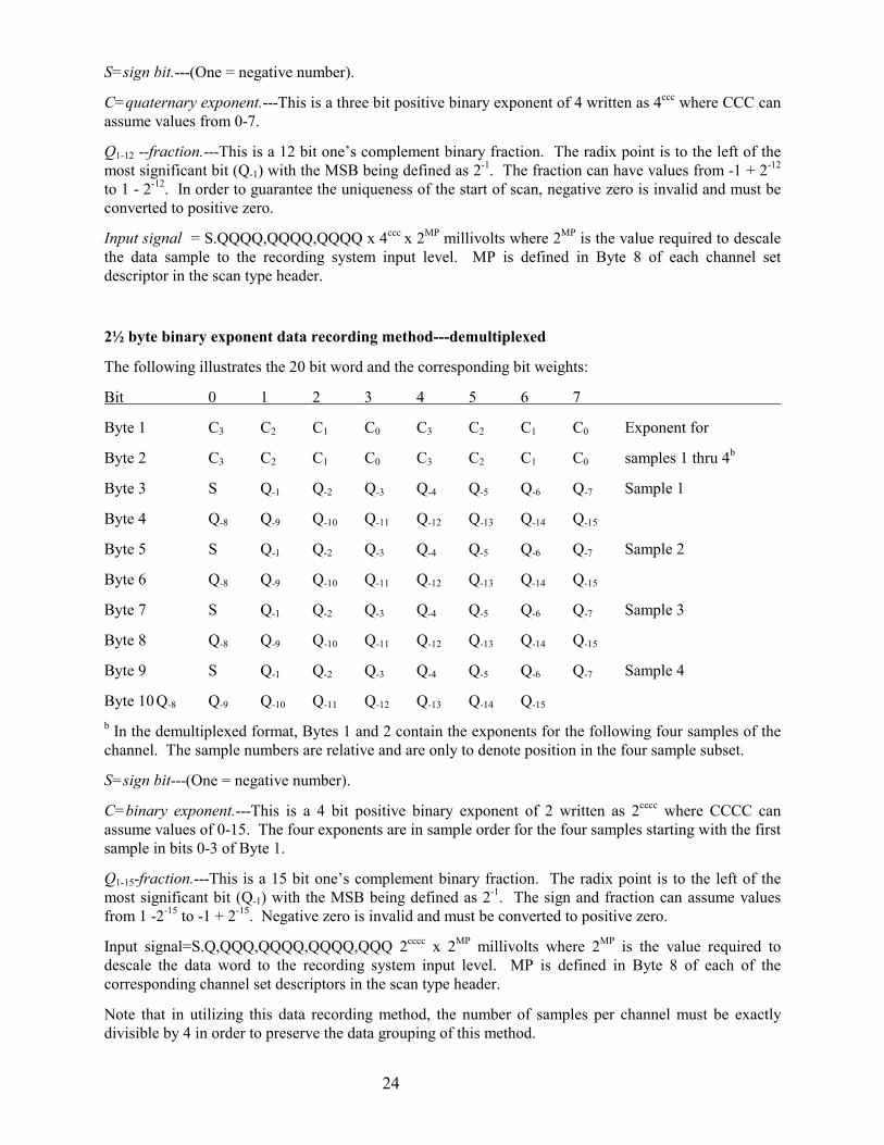
2½ byte binary exponent data recording method---demultiplexed
The following illustrates the 20 bit word and the corresponding bit weights:
Bit 0 1 2 3 4 5 6 7
Byte 1 C3 C2 C1 C0 C3 C2 C1 C0 Exponent for
Byte 2 C3 C2 C1 C0 C3 C2 C1 C0 samples 1 thru 4b
Byte 3 S Q-1 Q-2 Q-3 Q-4 Q-5 Q-6 Q-7 Sample 1
Byte 4 Q-8 Q-9 Q-10 Q-11 Q-12 Q-13 Q-14 Q-15
Byte 5 S Q-1 Q-2 Q-3 Q-4 Q-5 Q-6 Q-7 Sample 2
Byte 6 Q-8 Q-9 Q-10 Q-11 Q-12 Q-13 Q-14 Q-15
Byte 7 S Q-1 Q-2 Q-3 Q-4 Q-5 Q-6 Q-7 Sample 3
Byte 8 Q-8 Q-9 Q-10 Q-11 Q-12 Q-13 Q-14 Q-15
Byte 9 S Q-1 Q-2 Q-3 Q-4 Q-5 Q-6 Q-7 Sample 4
Byte 10 Q-8 Q-9 Q-10 Q-11 Q-12 Q-13 Q-14 Q-15
b In the demultiplexed format, Bytes 1 and 2 contain the exponents for the following four samples of thechannel. The sample numbers are relative and are only to denote position in the four sample subset.
S=sign bit---(One = negative number).
C=binary exponent.---This is a 4 bit positive binary exponent of 2 written as 2cccc where CCCC canassume values of 0-15. The four exponents are in sample order for the four samples starting with the firstsample in bits 0-3 of Byte 1.
Q1-15-fraction.---This is a 15 bit one’s complement binary fraction. The radix point is to the left of themost significant bit (Q-1) with the MSB being defined as 2-1. The sign and fraction can assume valuesfrom 1 -2-15 to -1 + 2-15. Negative zero is invalid and must be converted to positive zero.
Input signal=S.Q,QQQ,QQQQ,QQQQ,QQQ 2cccc x 2MP millivolts where 2MP is the value required todescale the data word to the recording system input level. MP is defined in Byte 8 of each of thecorresponding channel set descriptors in the scan type header.
Note that in utilizing this data recording method, the number of samples per channel must be exactlydivisible by 4 in order to preserve the data grouping of this method.
25
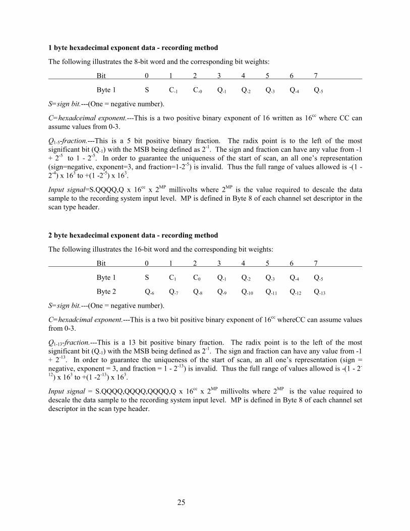
1 byte hexadecimal exponent data - recording method
The following illustrates the 8-bit word and the corresponding bit weights:
Bit 0 1 2 3 4 5 6 7
Byte 1 S C-1 C-0 Q-1 Q-2 Q-3 Q-4 Q-5
S=sign bit.---(One = negative number).
C=hexadceimal exponent.---This is a two positive binary exponent of 16 written as 16cc where CC canassume values from 0-3.
Q1-5-fraction.---This is a 5 bit positive binary fraction. The radix point is to the left of the mostsignificant bit (Q-1) with the MSB being defined as 2-1. The sign and fraction can have any value from -1+ 2-5 to 1 - 2-5. In order to guarantee the uniqueness of the start of scan, an all one’s representation(sign=negative, exponent=3, and fraction=1-2-5) is invalid. Thus the full range of values allowed is -(1 -2-4) x 163 to +(1 -2-5) x 163.
Input signal=S.QQQQ,Q x 16cc x 2MP millivolts where 2MP is the value required to descale the datasample to the recording system input level. MP is defined in Byte 8 of each channel set descriptor in thescan type header.
2 byte hexadecimal exponent data - recording method
The following illustrates the 16-bit word and the corresponding bit weights:
Bit 0 1 2 3 4 5 6 7
Byte 1 S C1 C0 Q-1 Q-2 Q-3 Q-4 Q-5
Byte 2 Q-6 Q-7 Q-8 Q-9 Q-10 Q-11 Q-12 Q-13
S=sign bit.---(One = negative number).
C=hexadcimal exponent.---This is a two bit positive binary exponent of 16cc whereCC can assume valuesfrom 0-3.
Q1-13-fraction.---This is a 13 bit positive binary fraction. The radix point is to the left of the mostsignificant bit (Q-1) with the MSB being defined as 2-1. The sign and fraction can have any value from -1+ 2-13. In order to guarantee the uniqueness of the start of scan, an all one’s representation (sign =negative, exponent = 3, and fraction = 1 - 2-13) is invalid. Thus the full range of values allowed is -(1 - 2-
12) x 163 to +(1 -2-13) x 163.
Input signal = S.QQQQ,QQQQ,QQQQ,Q x 16cc x 2MP millivolts where 2MP is the value required todescale the data sample to the recording system input level. MP is defined in Byte 8 of each channel setdescriptor in the scan type header.
26
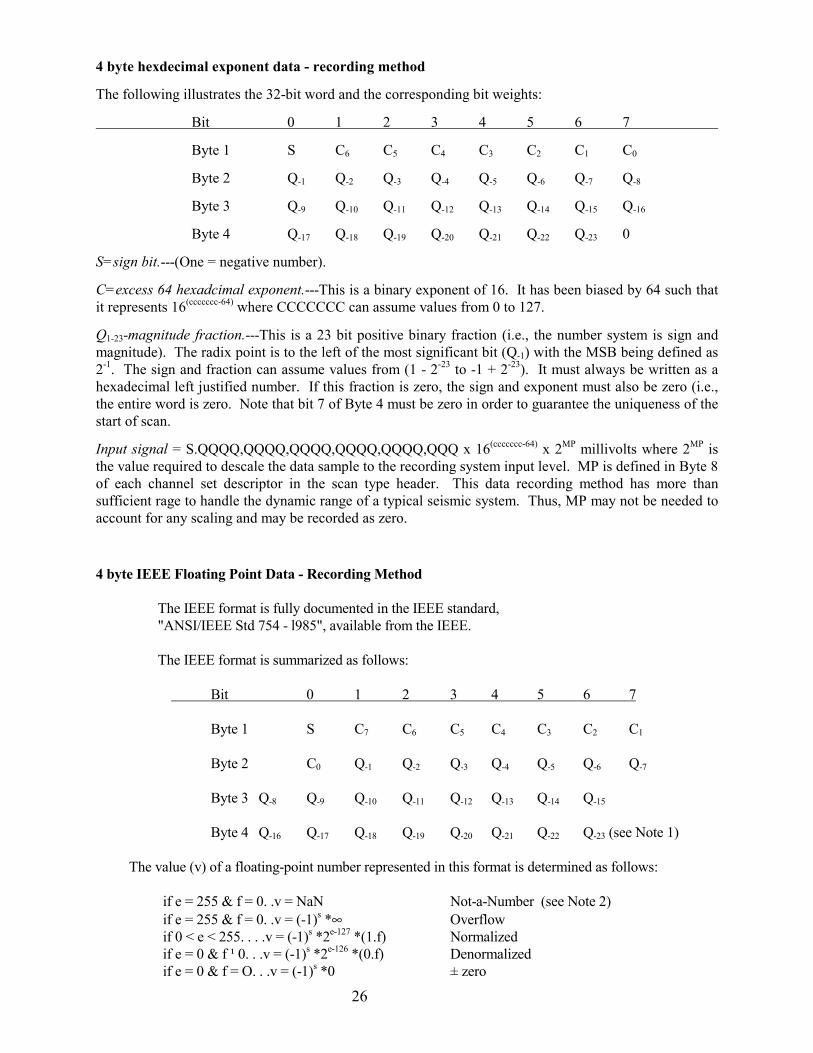
4 byte hexdecimal exponent data - recording method
The following illustrates the 32-bit word and the corresponding bit weights:
Bit 0 1 2 3 4 5 6 7
Byte 1 S C6 C5 C4 C3 C2 C1 C0
Byte 2 Q-1 Q-2 Q-3 Q-4 Q-5 Q-6 Q-7 Q-8
Byte 3 Q-9 Q-10 Q-11 Q-12 Q-13 Q-14 Q-15 Q-16
Byte 4 Q-17 Q-18 Q-19 Q-20 Q-21 Q-22 Q-23 0
S=sign bit.---(One = negative number).
C=excess 64 hexadcimal exponent.---This is a binary exponent of 16. It has been biased by 64 such thatit represents 16(ccccccc-64) where CCCCCCC can assume values from 0 to 127.
Q1-23-magnitude fraction.---This is a 23 bit positive binary fraction (i.e., the number system is sign andmagnitude). The radix point is to the left of the most significant bit (Q-1) with the MSB being defined as2-1. The sign and fraction can assume values from (1 - 2-23 to -1 + 2-23). It must always be written as ahexadecimal left justified number. If this fraction is zero, the sign and exponent must also be zero (i.e.,the entire word is zero. Note that bit 7 of Byte 4 must be zero in order to guarantee the uniqueness of thestart of scan.
Input signal = S.QQQQ,QQQQ,QQQQ,QQQQ,QQQQ,QQQ x 16(ccccccc-64) x 2MP millivolts where 2MP isthe value required to descale the data sample to the recording system input level. MP is defined in Byte 8of each channel set descriptor in the scan type header. This data recording method has more thansufficient rage to handle the dynamic range of a typical seismic system. Thus, MP may not be needed toaccount for any scaling and may be recorded as zero.
4 byte IEEE Floating Point Data - Recording Method
The IEEE format is fully documented in the IEEE standard, "ANSI/IEEE Std 754 - l985", available from the IEEE.
The IEEE format is summarized as follows:
Bit 0 1 2 3 4 5 6 7
Byte 1 S C7 C6 C5 C4 C3 C2 C1
Byte 2 C0 Q-1 Q-2 Q-3 Q-4 Q-5 Q-6 Q-7
Byte 3 Q-8 Q-9 Q-10 Q-11 Q-12 Q-13 Q-14 Q-15
Byte 4 Q-16 Q-17 Q-18 Q-19 Q-20 Q-21 Q-22 Q-23 (see Note 1)
The value (v) of a floating-point number represented in this format is determined as follows:
if e = 255 & f = 0. .v = NaN Not-a-Number (see Note 2)if e = 255 & f = 0. .v = (-1)s *∞ Overflowif 0 < e < 255. . . .v = (-1)s *2e-127 *(1.f) Normalizedif e = 0 & f ¹ 0. . .v = (-1)s *2e-126 *(0.f) Denormalizedif e = 0 & f = O. . .v = (-1)s *0 ± zero

27
where e = binary value of all C's (exponent)f = binary value of all Q's (fraction)
NOTES: 1. Bit 7 of byte 4 must be zero to guarantee uniqueness of the start of scan in theMultiplexed format (0058). It may be non zero in the demultiplexed format(8058).
2. A Not-a-Number (NaN) is interpreted as an invalid number. All other numbersare valid and interpreted as described above.
28
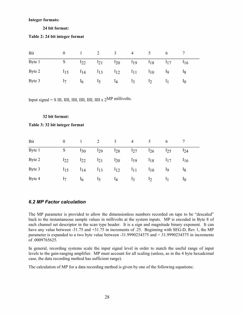
Integer formats:
24 bit format:
Table 2: 24 bit integer format
Bit 0 1 2 3 4 5 6 7
Byte 1 S I22 I21 I20 I19 I18 I17 I16
Byte 2 I15 I14 I13 I12 I11 I10 I9 I8
Byte 3 I7 I6 I5 I4 I3 I2 I1 I0
Input signal = S III, IIII, IIII, IIII, IIII, IIII x 2MP millivolts.
32 bit format:
Table 3: 32 bit integer format
Bit 0 1 2 3 4 5 6 7
Byte 1 S I30 I29 I28 I27 I26 I25 I24
Byte 2 I22 I22 I21 I20 I19 I18 I17 I16
Byte 3 I15 I14 I13 I12 I11 I10 I9 I8
Byte 4 I7 I6 I5 I4 I3 I2 I1 I0
6.2 MP Factor calculation
The MP parameter is provided to allow the dimensionless numbers recorded on tape to be “descaled”back to the instantaneous sample values in millivolts at the system inputs. MP is encoded in Byte 8 ofeach channel set descriptor in the scan type header. It is a sign and magnitude binary exponent. It canhave any value between -31.75 and +31.75 in increments of .25. Beginning with SEG-D, Rev 1, the MPparameter is expanded to a two byte value between -31.9990234375 and + 31.9990234375 in incrementsof .0009765625.
In general, recording systems scale the input signal level in order to match the useful range of inputlevels to the gain-ranging amplifier. MP must account for all scaling (unless, as in the 4 byte hexadcimalcase, the data recording method has sufficient range).
The calculation of MP for a data recording method is given by one of the following equations:
29
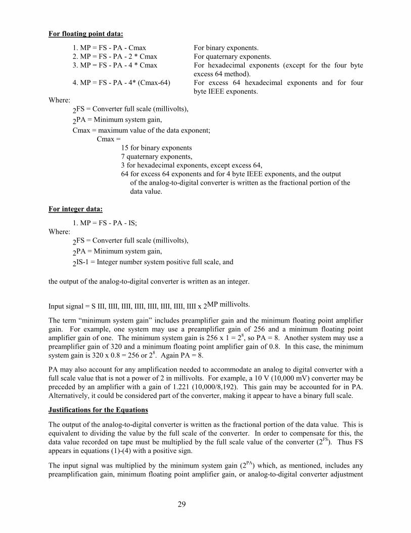
For floating point data:
1. MP = FS - PA - Cmax For binary exponents.2. MP = FS - PA - 2 * Cmax For quaternary exponents.3. MP = FS - PA - 4 * Cmax For hexadecimal exponents (except for the four byte
excess 64 method).4. MP = FS - PA - 4* (Cmax-64) For excess 64 hexadecimal exponents and for four
byte IEEE exponents.Where:
2FS = Converter full scale (millivolts),
2PA = Minimum system gain,Cmax = maximum value of the data exponent;
Cmax =15 for binary exponents7 quaternary exponents,3 for hexadecimal exponents, except excess 64,64 for excess 64 exponents and for 4 byte IEEE exponents, and the output
of the analog-to-digital converter is written as the fractional portion of thedata value.
For integer data:
1. MP = FS - PA - IS;Where:
2FS = Converter full scale (millivolts),
2PA = Minimum system gain,
2IS-1 = Integer number system positive full scale, and
the output of the analog-to-digital converter is written as an integer.
Input signal = S III, IIII, IIII, IIII, IIII, IIII, IIII, IIII x 2MP millivolts.
The term “minimum system gain” includes preamplifier gain and the minimum floating point amplifiergain. For example, one system may use a preamplifier gain of 256 and a minimum floating pointamplifier gain of one. The minimum system gain is 256 x 1 = 28, so PA = 8. Another system may use apreamplifier gain of 320 and a minimum floating point amplifier gain of 0.8. In this case, the minimumsystem gain is 320 x 0.8 = 256 or 28. Again PA = 8.
PA may also account for any amplification needed to accommodate an analog to digital converter with afull scale value that is not a power of 2 in millivolts. For example, a 10 V (10,000 mV) converter may bepreceded by an amplifier with a gain of 1.221 (10,000/8,192). This gain may be accounted for in PA.Alternatively, it could be considered part of the converter, making it appear to have a binary full scale.
Justifications for the Equations
The output of the analog-to-digital converter is written as the fractional portion of the data value. This isequivalent to dividing the value by the full scale of the converter. In order to compensate for this, thedata value recorded on tape must be multiplied by the full scale value of the converter (2FS). Thus FSappears in equations (1)-(4) with a positive sign.
The input signal was multiplied by the minimum system gain (2PA) which, as mentioned, includes anypreamplification gain, minimum floating point amplifier gain, or analog-to-digital converter adjustment

30
gain. The data recorded on tape must be divided by this minimum system gain; thus, PA appears in theequations with a negative sign.
Large input signals converted at minimum floating point amplifier gain are written on tape with themaximum exponent for the data recording method used. Likewise, small signals converted at full gainare written with the maximum exponent. The data as written have been multiplied by the exponent baseraised to Cmax (or Cmax -64 in the excess 64 case). Thus Cmax appears in the equations with a negativesign. MP is a power of 2 so the quaternary and hexadecimal Cmax values are multiplied by 2 and 4,respectively (4c = 22c and 16c = 24c).
31
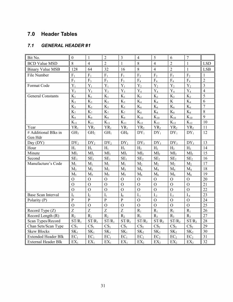
7.0 Header Tables
7.1 GENERAL HEADER #1
Bit No. 0 1 2 3 4 5 6 7BCD Value MSD 8 4 2 1 8 4 2 1 LSDBinary Value MSB 128 64 32 16 8 4 2 1 LSBFile Number F1 F1 F1 F1 F2 F2 F2 F2 1
F3 F3 F3 F3 F4 F4 F4 F4 2Format Code Y1 Y1 Y1 Y1 Y2 Y2 Y2 Y2 3
Y3 Y3 Y3 Y3 Y4 Y4 Y4 Y4 4General Constants K1 K1 K1 K1 K2 K2 K2 K2 5
K3 K3 K3 K3 K4 K4 K K4 6K5 K5 K5 K5 K6 K6 K6 K6 7K7 K7 K7 K7 K8 K8 K8 K8 8K9 K9 K9 K9 K10 K10 K10 K10 9K11 K11 K11 K11 K12 K12 K12 K12 10
Year YR1 YR1 YR1 YR1 YR2 YR2 YR2 YR2 11# Additional Blks inGen Hdr
GH3 GH2 GH1 GH0 DY1 DY1 DY1 DY1 12
Day (DY) DY2 DY2 DY2 DY2 DY3 DY3 DY3 DY3 13Hour H1 H1 H1 H1 H2 H2 H2 H2 14Minute MI1 MI1 MI1 MI1 MI2 MI2 MI2 MI2 15Second SE1 SE1 SE1 SE1 SE2 SE2 SE2 SE2 16Manufacture’s Code M1 M1 M1 M1 M2 M2 M2 M2 17
M3 M3 M3 M3 M4 M4 M4 M4 18M5 M5 M5 M5 M6 M6 M6 M6 19O O O O O O O O 20O O O O O O O O 21O O O O O O O O 22
Base Scan Interval I3 I2 I1 I0 I-1 I-2 I-3 I-4 23Polarity (P) P P P P O O O O 24
O O O O O O O O 25Record Type (Z) Z Z Z Z R1 R1 R1 R1 26Record Length (R) R2 R2 R2 R2 R3 R3 R3 R3 27Scan Types/Record ST/R1 ST/R1 ST/R1 ST/R1 ST/R2 ST/R2 ST/R2 ST/R2 28Chan Sets/Scan Type CS1 CS1 CS1 CS1 CS2 CS2 CS2 CS2 29Skew Blocks SK1 SK1 SK1 SK1 SK2 SK2 SK2 SK2 30Extended Header Blk EC1 EC1 EC1 EC1 EC2 EC2 EC2 EC2 31External Header Blk EX1 EX1 EX1 EX1 EX2 EX2 EX2 EX2 32
32
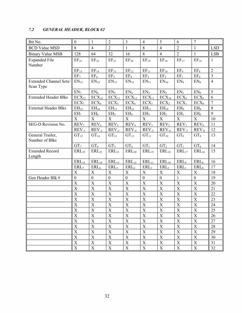
7.2 GENERAL HEADER, BLOCK #2
Bit No. 0 1 2 3 4 5 6 7BCD Value MSD 8 4 2 1 8 4 2 1 LSDBinary Value MSB 128 64 32 16 8 4 2 1 LSBExpanded FileNumber
EF23 EF22 EF21 EF20 EF19 EF18 EF17 EF16 1
EF15 EF14 EF13 EF12 EF11 EF10 EF9 EF8 2EF7 EF6 EF5 EF4 EF3 EF2 EF1 EF0 3
Extended Channel Sets/Scan Type
EN15 EN14 EN13 EN12 EN11 EN10 EN9 EN8 4
EN7 EN6 EN5 EN4 EN3 EN2 EN1 EN0 5Extended Header Blks ECX15 ECX14 ECX13 ECX12 ECX11 ECX10 ECX9 ECX8 6
ECX7 ECX6 ECX5 ECX4 ECX3 ECX2 ECX1 ECX0 7External Header Blks EH15 EH14 EH13 EH12 EH11 EH10 EH9 EH8 8
EH7 EH6 EH5 EH4 EH3 EH2 EH1 EH0 9X X X X X X X X 10
SEG-D Revision No. REV7 REV6 REV5 REV4 REV3 REV2 REV1 REV0 11REV-1 REV-2 REV-3 REV-4 REV-5 REV-6 REV-7 REV-8 12
General Trailer,Number of Blks
GT15 GT14 GT13 GT12 GT11 GT10 GT9 GT8 13
GT7 GT6 GT5 GT4 GT3 GT2 GT1 GT0 14Extended RecordLength
ERL23 ERL22 ERL21 ERL20 ERL19 ERL18 ERL17 ERL16 15
ERL15 ERL14 ERL13 ERL12 ERL11 ERL10 ERL9 ERL8 16ERL7 ERL6 ERL5 ERL4 ERL3 ERL2 ERL1 ERL0 17X X X X X X X X 18
Gen Header Blk # 0 0 0 0 0 0 1 0 19X X X X X X X X 20X X X X X X X X 21X X X X X X X X 22X X X X X X X X 23X X X X X X X X 24X X X X X X X X 25X X X X X X X X 26X X X X X X X X 27X X X X X X X X 28X X X X X X X X 29X X X X X X X X 30X X X X X X X X 31X X X X X X X X 32
33
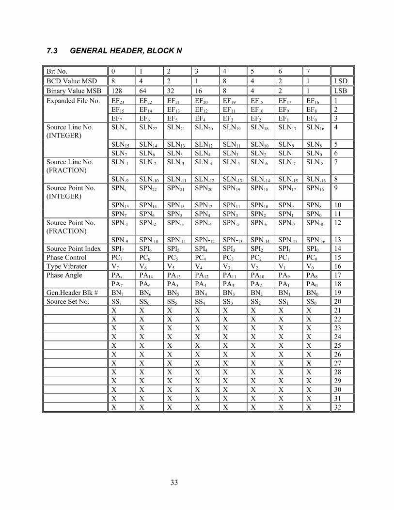
7.3 GENERAL HEADER, BLOCK N
Bit No. 0 1 2 3 4 5 6 7BCD Value MSD 8 4 2 1 8 4 2 1 LSDBinary Value MSB 128 64 32 16 8 4 2 1 LSBExpanded File No. EF23 EF22 EF21 EF20 EF19 EF18 EF17 EF16 1
EF15 EF14 EF13 EF12 EF11 EF10 EF9 EF8 2EF7 EF6 EF5 EF4 EF3 EF2 EF1 EF0 3
Source Line No.(INTEGER)
SLNs SLN22 SLN21 SLN20 SLN19 SLN18 SLN17 SLN16 4
SLN15 SLN14 SLN13 SLN12 SLN11 SLN10 SLN9 SLN8 5SLN7 SLN6 SLN5 SLN4 SLN3 SLN2 SLN1 SLN0 6
Source Line No.(FRACTION)
SLN-1 SLN-2 SLN-3 SLN-4 SLN-5 SLN-6 SLN-7 SLN-8 7
SLN-9 SLN-10 SLN-11 SLN-12 SLN-13 SLN-14 SLN-15 SLN-16 8Source Point No.(INTEGER)
SPNs SPN22 SPN21 SPN20 SPN19 SPN18 SPN17 SPN16 9
SPN15 SPN14 SPN13 SPN12 SPN11 SPN10 SPN9 SPN8 10SPN7 SPN6 SPN5 SPN4 SPN3 SPN2 SPN1 SPN0 11
Source Point No.(FRACTION)
SPN-1 SPN-2 SPN-3 SPN-4 SPN-5 SPN-6 SPN-7 SPN-8 12
SPN-9 SPN-10 SPN-11 SPN-12 SPN-13 SPN-14 SPN-15 SPN-16 13Source Point Index SPI7 SPI6 SPI5 SPI4 SPI3 SPI2 SPI1 SPI0 14Phase Control PC7 PC6 PC5 PC4 PC3 PC2 PC1 PC0 15Type Vibrator V7 V6 V5 V4 V3 V2 V1 V0 16Phase Angle PAs PA14 PA13 PA12 PA11 PA10 PA9 PA8 17
PA7 PA6 PA5 PA4 PA3 PA2 PA1 PA0 18Gen.Header Blk # BN7 BN6 BN5 BN4 BN3 BN2 BN1 BN0 19Source Set No. SS7 SS6 SS5 SS4 SS3 SS2 SS1 SS0 20
X X X X X X X X 21X X X X X X X X 22X X X X X X X X 23X X X X X X X X 24X X X X X X X X 25X X X X X X X X 26X X X X X X X X 27X X X X X X X X 28X X X X X X X X 29X X X X X X X X 30X X X X X X X X 31X X X X X X X X 32
34
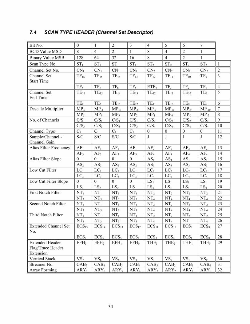
7.4 SCAN TYPE HEADER (Channel Set Descriptor)
Bit No. 0 1 2 3 4 5 6 7BCD Value MSD 8 4 2 1 8 4 2 1Binary Value MSB 128 64 32 16 8 4 2 1Scan Type No. ST1 ST1 ST1 ST1 ST2 ST2 ST2 ST2 1Channel Set No. CN1 CN1 CN1 CN1 CN2 CN2 CN2 CN2 2Channel SetStart Time
TF16 TF15 TE14 TF13 TF12 TF11 TF10 TF9 3
TF8 TF7 TF6 TF5 ETF4 TF3 TF2 TF1 4Channel SetEnd Time
TE16 TE15 TE14 TE13 TE12 TE11 TE10 TE9 5
TE8 TE7 TE13 TE12 TE11 TE10 TE9 TE8 6Descale Multiplier MP-3 MP-4 MP-5 MP-6 MP-7 MP-8 MP-9 MP-10 7
MP5 MP4 MP3 MP2 MP1 MP0 MP-1 MP-2 8No. of Channels C/S1 C/S1 C/S1 C/S1 C/S2 C/S2 C/S2 C/S2 9
C/S3 C/S3 C/S3 C/S3 C/S4 C/S4 C/S4 C/S4 10Channel Type C1 C1 C1 C1 0 0 0 0 11Sample/Channel -Channel Gain
S/C S/C S/C S/C J J J J 12
Alias Filter Frequency AF1 AF1 AF1 AF1 AF2 AF2 AF2 AF2 13AF3 AF3 AF3 AF3 AF4 AF4 AF4 AF4 14
Alias Filter Slope 0 0 0 0 AS1 AS1 AS1 AS1 15AS2 AS2 AS2 AS2 AS3 AS3 AS3 AS3 16
Low Cut Filter LC1 LC1 LC1 LC1 LC2 LC2 LC2 LC2 17LC3 LC3 LC3 LC3 LC4 LC4 LC4 LC4 18
Low Cut Filter Slope 0 0 0 0 LS1 LS1 LS1 LS1 19LS2 LS2 LS2 LS LS3 LS3 LS3 LS3 20
First Notch Filter NT1 NT1 NT1 NT1 NT2 NT2 NT2 NT2 21NT3 NT3 NT3 NT3 NT4 NT4 NT4 NT4 22
Second Notch Filter NT1 NT1 NT1 NT1 NT2 NT2 NT2 NT2 23NT3 NT3 NT3 NT3 NT4 NT4 NT4 NT4 24
Third Notch Filter NT1 NT1 NT1 NT1 NT2 NT2 NT2 NT2 25NT3 NT3 NT3 NT3 NT4 NT4 NT NT4 26
Extended Channel SetNo.
ECS15 ECS14 ECS13 ECS12 ECS11 ECS10 ECS9 ECS8 27
ECS7 ECS6 ECS5 ECS4 ECS3 ECS2 ECS1 ECS0 28Extended HeaderFlag/Trace HeaderExtension
EFH3 EFH2 EFH1 EFH0 THE3 THE2 THE1 THE0 29
Vertical Stack VS7 VS6 VS5 VS4 VS3 VS2 VS1 VS0 30Streamer No. CAB7 CAB6 CAB5 CAB4 CAB3 CAB2 CAB1 CAB0 31Array Forming ARY7 ARY6 ARY5 ARY4 ARY3 ARY2 ARY1 ARY0 32
35
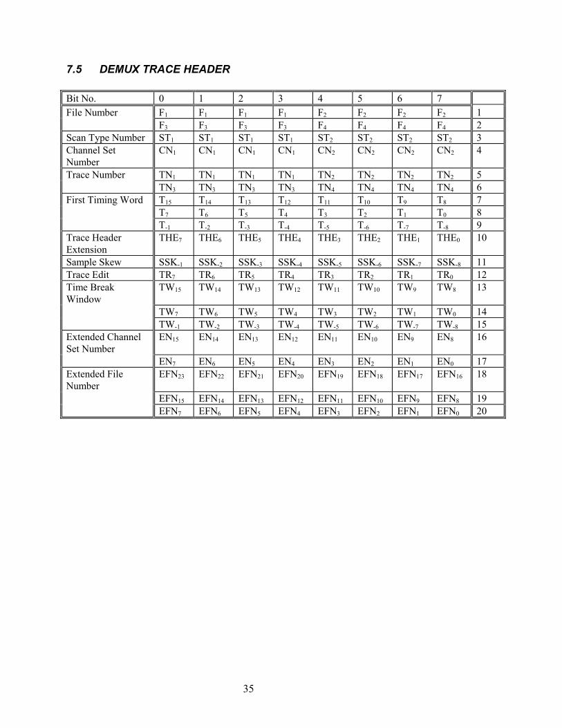
7.5 DEMUX TRACE HEADER
Bit No. 0 1 2 3 4 5 6 7File Number F1 F1 F1 F1 F2 F2 F2 F2 1
F3 F3 F3 F3 F4 F4 F4 F4 2Scan Type Number ST1 ST1 ST1 ST1 ST2 ST2 ST2 ST2 3Channel SetNumber
CN1 CN1 CN1 CN1 CN2 CN2 CN2 CN2 4
Trace Number TN1 TN1 TN1 TN1 TN2 TN2 TN2 TN2 5TN3 TN3 TN3 TN3 TN4 TN4 TN4 TN4 6
First Timing Word T15 T14 T13 T12 T11 T10 T9 T8 7T7 T6 T5 T4 T3 T2 T1 T0 8T-1 T-2 T-3 T-4 T-5 T-6 T-7 T-8 9
Trace HeaderExtension
THE7 THE6 THE5 THE4 THE3 THE2 THE1 THE0 10
Sample Skew SSK-1 SSK-2 SSK-3 SSK-4 SSK-5 SSK-6 SSK-7 SSK-8 11Trace Edit TR7 TR6 TR5 TR4 TR3 TR2 TR1 TR0 12Time BreakWindow
TW15 TW14 TW13 TW12 TW11 TW10 TW9 TW8 13
TW7 TW6 TW5 TW4 TW3 TW2 TW1 TW0 14TW-1 TW-2 TW-3 TW-4 TW-5 TW-6 TW-7 TW-8 15
Extended ChannelSet Number
EN15 EN14 EN13 EN12 EN11 EN10 EN9 EN8 16
EN7 EN6 EN5 EN4 EN3 EN2 EN1 EN0 17Extended FileNumber
EFN23 EFN22 EFN21 EFN20 EFN19 EFN18 EFN17 EFN16 18
EFN15 EFN14 EFN13 EFN12 EFN11 EFN10 EFN9 EFN8 19EFN7 EFN6 EFN5 EFN4 EFN3 EFN2 EFN1 EFN0 20
36
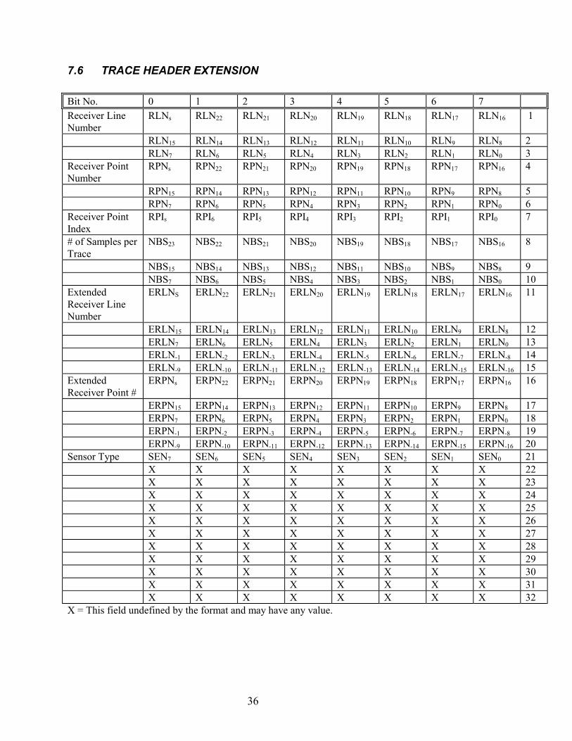
7.6 TRACE HEADER EXTENSION
Bit No. 0 1 2 3 4 5 6 7Receiver LineNumber
RLNs RLN22 RLN21 RLN20 RLN19 RLN18 RLN17 RLN16 1
RLN15 RLN14 RLN13 RLN12 RLN11 RLN10 RLN9 RLN8 2RLN7 RLN6 RLN5 RLN4 RLN3 RLN2 RLN1 RLN0 3
Receiver PointNumber
RPNs RPN22 RPN21 RPN20 RPN19 RPN18 RPN17 RPN16 4
RPN15 RPN14 RPN13 RPN12 RPN11 RPN10 RPN9 RPN8 5RPN7 RPN6 RPN5 RPN4 RPN3 RPN2 RPN1 RPN0 6
Receiver PointIndex
RPIs RPI6 RPI5 RPI4 RPI3 RPI2 RPI1 RPI0 7
# of Samples perTrace
NBS23 NBS22 NBS21 NBS20 NBS19 NBS18 NBS17 NBS16 8
NBS15 NBS14 NBS13 NBS12 NBS11 NBS10 NBS9 NBS8 9NBS7 NBS6 NBS5 NBS4 NBS3 NBS2 NBS1 NBS0 10
ExtendedReceiver LineNumber
ERLNS ERLN22 ERLN21 ERLN20 ERLN19 ERLN18 ERLN17 ERLN16 11
ERLN15 ERLN14 ERLN13 ERLN12 ERLN11 ERLN10 ERLN9 ERLN8 12ERLN7 ERLN6 ERLN5 ERLN4 ERLN3 ERLN2 ERLN1 ERLN0 13ERLN-1 ERLN-2 ERLN-3 ERLN-4 ERLN-5 ERLN-6 ERLN-7 ERLN-8 14ERLN-9 ERLN-10 ERLN-11 ERLN-12 ERLN-13 ERLN-14 ERLN-15 ERLN-16 15
ExtendedReceiver Point #
ERPNs ERPN22 ERPN21 ERPN20 ERPN19 ERPN18 ERPN17 ERPN16 16
ERPN15 ERPN14 ERPN13 ERPN12 ERPN11 ERPN10 ERPN9 ERPN8 17ERPN7 ERPN6 ERPN5 ERPN4 ERPN3 ERPN2 ERPN1 ERPN0 18ERPN-1 ERPN-2 ERPN-3 ERPN-4 ERPN-5 ERPN-6 ERPN-7 ERPN-8 19ERPN-9 ERPN-10 ERPN-11 ERPN-12 ERPN-13 ERPN-14 ERPN-15 ERPN-16 20
Sensor Type SEN7 SEN6 SEN5 SEN4 SEN3 SEN2 SEN1 SEN0 21X X X X X X X X 22X X X X X X X X 23X X X X X X X X 24X X X X X X X X 25X X X X X X X X 26X X X X X X X X 27X X X X X X X X 28X X X X X X X X 29X X X X X X X X 30X X X X X X X X 31X X X X X X X X 32
X = This field undefined by the format and may have any value.
37
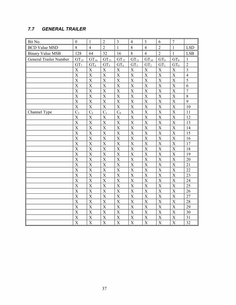
7.7 GENERAL TRAILER
Bit No. 0 1 2 3 4 5 6 7BCD Value MSD 8 4 2 1 8 4 2 1 LSDBinary Value MSB 128 64 32 16 8 4 2 1 LSBGeneral Trailer Number GT15 GT14 GT13 GT12 GT11 GT10 GT9 GT8 1
GT7 GT6 GT5 GT4 GT3 GT2 GT1 GT0 2X X X X X X X X 3X X X X X X X X 4X X X X X X X X 5X X X X X X X X 6X X X X X X X X 7X X X X X X X X 8X X X X X X X X 9X X X X X X X X 10
Channel Type C3 C2 C1 C0 X X X X 11X X X X X X X X 12X X X X X X X X 13X X X X X X X X 14X X X X X X X X 15X X X X X X X X 16X X X X X X X X 17X X X X X X X X 18X X X X X X X X 19X X X X X X X X 20X X X X X X X X 21X X X X X X X X 22X X X X X X X X 23X X X X X X X X 24X X X X X X X X 25X X X X X X X X 26X X X X X X X X 27X X X X X X X X 28X X X X X X X X 29X X X X X X X X 30X X X X X X X X 31X X X X X X X X 32
38
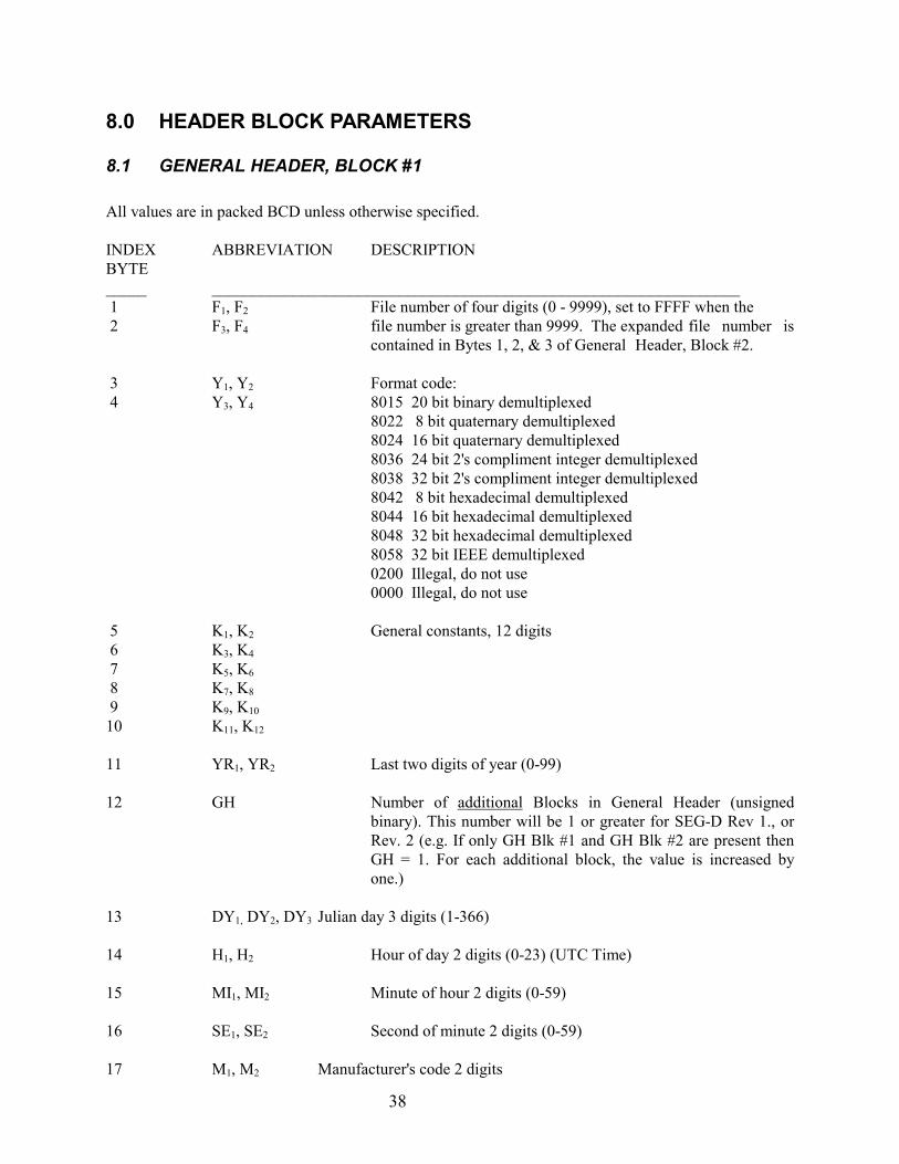
8.0 HEADER BLOCK PARAMETERS
8.1 GENERAL HEADER, BLOCK #1
All values are in packed BCD unless otherwise specified.
INDEX ABBREVIATION DESCRIPTIONBYTE_____ _________________________________________________________________ 1 F1, F2 File number of four digits (0 - 9999), set to FFFF when the 2 F3, F4 file number is greater than 9999. The expanded file number is
contained in Bytes 1, 2, & 3 of General Header, Block #2.
3 Y1, Y2 Format code: 4 Y3, Y4 8015 20 bit binary demultiplexed
8022 8 bit quaternary demultiplexed8024 16 bit quaternary demultiplexed8036 24 bit 2's compliment integer demultiplexed8038 32 bit 2's compliment integer demultiplexed8042 8 bit hexadecimal demultiplexed8044 16 bit hexadecimal demultiplexed8048 32 bit hexadecimal demultiplexed8058 32 bit IEEE demultiplexed0200 Illegal, do not use0000 Illegal, do not use
5 K1, K2 General constants, 12 digits 6 K3, K4
7 K5, K6
8 K7, K8
9 K9, K10
10 K11, K12
11 YR1, YR2 Last two digits of year (0-99)
12 GH Number of additional Blocks in General Header (unsignedbinary). This number will be 1 or greater for SEG-D Rev 1., orRev. 2 (e.g. If only GH Blk #1 and GH Blk #2 are present thenGH = 1. For each additional block, the value is increased byone.)
13 DY1, DY2, DY3 Julian day 3 digits (1-366) 14 H1, H2 Hour of day 2 digits (0-23) (UTC Time)
15 MI1, MI2 Minute of hour 2 digits (0-59)
16 SE1, SE2 Second of minute 2 digits (0-59)
17 M1, M2 Manufacturer's code 2 digits
39
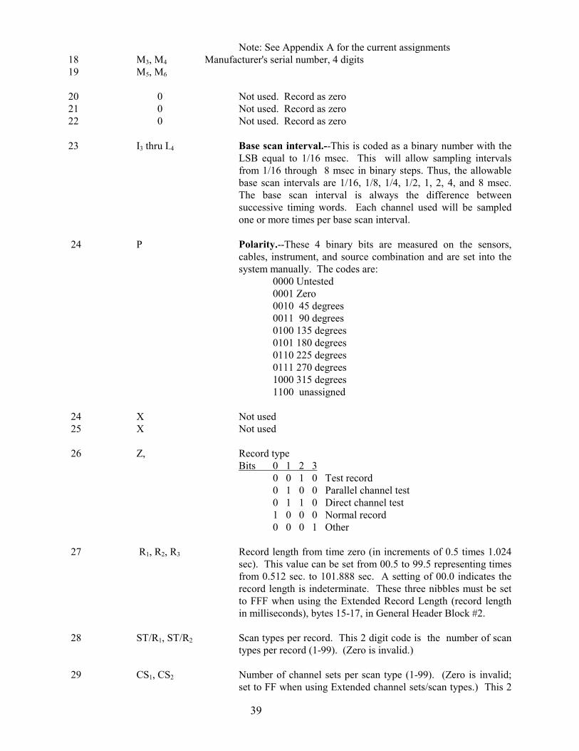
Note: See Appendix A for the current assignments18 M3, M4 Manufacturer's serial number, 4 digits19 M5, M6
20 0 Not used. Record as zero21 0 Not used. Record as zero22 0 Not used. Record as zero
23 I3 thru I-4 Base scan interval.--This is coded as a binary number with theLSB equal to 1/16 msec. This will allow sampling intervalsfrom 1/16 through 8 msec in binary steps. Thus, the allowablebase scan intervals are 1/16, 1/8, 1/4, 1/2, 1, 2, 4, and 8 msec.The base scan interval is always the difference betweensuccessive timing words. Each channel used will be sampledone or more times per base scan interval.
24 P Polarity.--These 4 binary bits are measured on the sensors,cables, instrument, and source combination and are set into thesystem manually. The codes are:
0000 Untested0001 Zero0010 45 degrees0011 90 degrees0100 135 degrees0101 180 degrees0110 225 degrees0111 270 degrees1000 315 degrees1100 unassigned
24 X Not used 25 X Not used
26 Z, Record typeBits 0 1 2 3
0 0 1 0 Test record0 1 0 0 Parallel channel test0 1 1 0 Direct channel test1 0 0 0 Normal record0 0 0 1 Other
27 R1, R2, R3 Record length from time zero (in increments of 0.5 times 1.024sec). This value can be set from 00.5 to 99.5 representing timesfrom 0.512 sec. to 101.888 sec. A setting of 00.0 indicates therecord length is indeterminate. These three nibbles must be setto FFF when using the Extended Record Length (record lengthin milliseconds), bytes 15-17, in General Header Block #2.
28 ST/R1, ST/R2 Scan types per record. This 2 digit code is the number of scantypes per record (1-99). (Zero is invalid.)
29 CS1, CS2 Number of channel sets per scan type (1-99). (Zero is invalid;set to FF when using Extended channel sets/scan types.) This 2
40
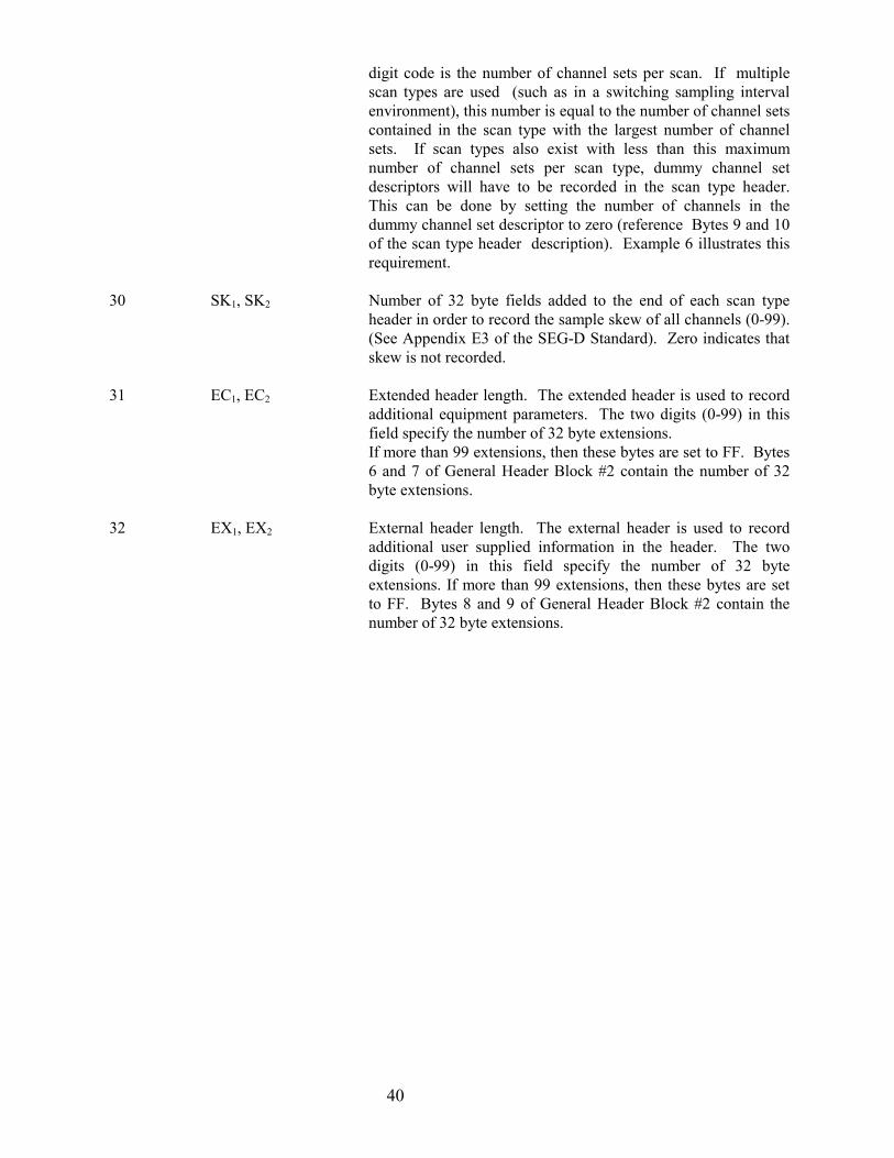
digit code is the number of channel sets per scan. If multiplescan types are used (such as in a switching sampling intervalenvironment), this number is equal to the number of channel setscontained in the scan type with the largest number of channelsets. If scan types also exist with less than this maximumnumber of channel sets per scan type, dummy channel setdescriptors will have to be recorded in the scan type header.This can be done by setting the number of channels in thedummy channel set descriptor to zero (reference Bytes 9 and 10of the scan type header description). Example 6 illustrates thisrequirement.
30 SK1, SK2 Number of 32 byte fields added to the end of each scan typeheader in order to record the sample skew of all channels (0-99).(See Appendix E3 of the SEG-D Standard). Zero indicates thatskew is not recorded.
31 EC1, EC2 Extended header length. The extended header is used to recordadditional equipment parameters. The two digits (0-99) in thisfield specify the number of 32 byte extensions.If more than 99 extensions, then these bytes are set to FF. Bytes6 and 7 of General Header Block #2 contain the number of 32byte extensions.
32 EX1, EX2 External header length. The external header is used to recordadditional user supplied information in the header. The twodigits (0-99) in this field specify the number of 32 byteextensions. If more than 99 extensions, then these bytes are setto FF. Bytes 8 and 9 of General Header Block #2 contain thenumber of 32 byte extensions.
41
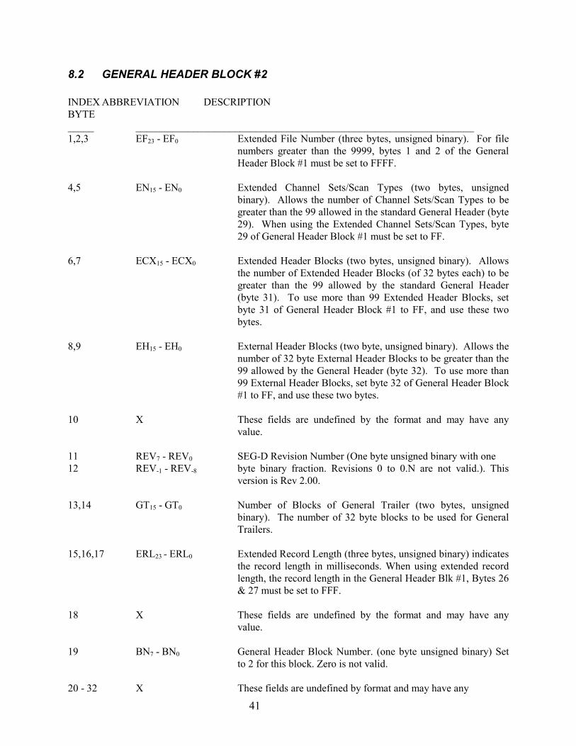
8.2 GENERAL HEADER BLOCK #2
INDEX ABBREVIATION DESCRIPTIONBYTE_____ _________________________________________________________________1,2,3 EF23 - EF0 Extended File Number (three bytes, unsigned binary). For file
numbers greater than the 9999, bytes 1 and 2 of the GeneralHeader Block #1 must be set to FFFF.
4,5 EN15 - EN0 Extended Channel Sets/Scan Types (two bytes, unsignedbinary). Allows the number of Channel Sets/Scan Types to begreater than the 99 allowed in the standard General Header (byte29). When using the Extended Channel Sets/Scan Types, byte29 of General Header Block #1 must be set to FF.
6,7 ECX15 - ECX0 Extended Header Blocks (two bytes, unsigned binary). Allowsthe number of Extended Header Blocks (of 32 bytes each) to begreater than the 99 allowed by the standard General Header(byte 31). To use more than 99 Extended Header Blocks, setbyte 31 of General Header Block #1 to FF, and use these twobytes.
8,9 EH15 - EH0 External Header Blocks (two byte, unsigned binary). Allows thenumber of 32 byte External Header Blocks to be greater than the99 allowed by the General Header (byte 32). To use more than99 External Header Blocks, set byte 32 of General Header Block#1 to FF, and use these two bytes.
10 X These fields are undefined by the format and may have anyvalue.
11 REV7 - REV0 SEG-D Revision Number (One byte unsigned binary with one12 REV-1 - REV-8 byte binary fraction. Revisions 0 to 0.N are not valid.). This
version is Rev 2.00.
13,14 GT15 - GT0 Number of Blocks of General Trailer (two bytes, unsignedbinary). The number of 32 byte blocks to be used for GeneralTrailers.
15,16,17 ERL23 - ERL0 Extended Record Length (three bytes, unsigned binary) indicatesthe record length in milliseconds. When using extended recordlength, the record length in the General Header Blk #1, Bytes 26& 27 must be set to FFF.
18 X These fields are undefined by the format and may have anyvalue.
19 BN7 - BN0 General Header Block Number. (one byte unsigned binary) Setto 2 for this block. Zero is not valid.
20 - 32 X These fields are undefined by format and may have any

42
value.
NOTES: 1. Where the range of allowable numbers is not indicated, the follow ranges apply.
Two byte unsigned binary, range is 0 - FF,Four byte unsigned binary, range is 0 - FFFF,Three byte, two's complement, signed binary; range is -7FFFFF to +7FFFFF
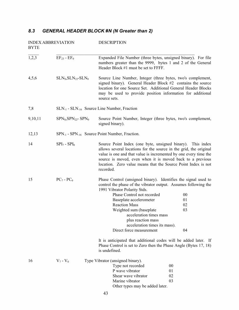
43
8.3 GENERAL HEADER BLOCK #N (N Greater than 2)
INDEX ABBREVIATION DESCRIPTIONBYTE_____ ________________________________________________________________1,2,3 EF23 - EF0 Expanded File Number (three bytes, unsigned binary). For file
numbers greater than the 9999, bytes 1 and 2 of the GeneralHeader Block #1 must be set to FFFF.
4,5,6 SLNS,SLN22-SLN0 Source Line Number, Integer (three bytes, two's complement,signed binary). General Header Block #2 contains the sourcelocation for one Source Set. Additional General Header Blocksmay be used to provide position information for additionalsource sets.
7,8 SLN-1 - SLN-16 Source Line Number, Fraction
9,10,11 SPNS,SPN22- SPN0 Source Point Number, Integer (three bytes, two's complement,signed binary).
12,13 SPN-1 - SPN-16 Source Point Number, Fraction.
14 SPI7 - SPI0 Source Point Index (one byte, unsigned binary). This indexallows several locations for the source in the grid, the originalvalue is one and that value is incremented by one every time thesource is moved, even when it is moved back to a previouslocation. Zero value means that the Source Point Index is notrecorded.
15 PC7 - PC0 Phase Control (unsigned binary). Identifies the signal used tocontrol the phase of the vibrator output. Assumes following the1991 Vibrator Polarity Stds.
Phase Control not recorded 00Baseplate accelerometer 01Reaction Mass 02Weighted sum (baseplate 03
acceleration times massplus reaction mass acceleration times its mass).
Direct force measurement 04
It is anticipated that additional codes will be added later. IfPhase Control is set to Zero then the Phase Angle (Bytes 17, 18)is undefined.
16 V7 - V0 Type Vibrator (unsigned binary).Type not recorded 00P wave vibrator 01Shear wave vibrator 02Marine vibrator 03Other types may be added later.
44
17,18 PAS, PA14 - PA0Phase Angle (two bytes, two's complement, signed binary). The Phaseangle of the intercept of the pilot signal with respect to the phasefeedback signal, measured in degrees. Phase Angle is set to zerowhen Phase Control (Byte 15) is zero (Phase Control notrecorded).
19 BN7 - BN0 General Header Block Number (one byte unsigned binary). Setto N for this block. Zero is not valid.
20 SS7 - SS0 Source Set Number (unsigned binary). Used to allow multiplesets of sources. Zero is not valid.
21-32 X These fields are undefined by format and may have any value.
8.4 SCAN TYPE HEADER (channel set descriptor)
The scan type header is determined by the system configuration and consists of one or more channel setdescriptors each of 32 bytes followed by a series of 32 byte sample skew fields. A channel set is definedas a group of channels operating with the same set of parameters and being sampled as part of a scan ofdata. A scan type header can be composed of from 1 to 99 channel set descriptors. If dynamic parameterchanges are required during the recording, additional scan type headers must be added, each containingthe channel set descriptors necessary to define the new parameters. Each scan type header must have thesame number of channel set descriptors (see Appendix E.4).
8.5 CHANNEL SET DESCRIPTOR
INDEX ABBREVIATION DESCRIPTIONBYTE_____ _________________________________________________________________1 ST1, ST2 These two digits (1-99) identify the number of the scan type
header to be described by the subsequent bytes. The first scantype header is 1 and the last scan type header number is the samevalue as Byte 28 (ST/R) of the General Header Block #1. If ascan type header contains more than one channel set descriptor,the scan type header number will be repeated in each of itschannel set descriptors. If the system does not have dynamicparameter changes during the record, such as switched samplingintervals, there will only be one scan type header required.
2 CN1, CN2 These two digits (1-99) identify the channel set to be describedin the next 30 bytes within this scan type header. The firstchannel set is "1" and the last channel set number is the samenumber as Byte 29 (CS) of the General Header Block #1. If thescan actually contains fewer channel sets than CS, then dummychannel set descriptors are included as specified in Byte 29 ofGeneral Header Block #1. Set to FF when using Channel Setsbeyond 99.
3 TF16 thru TF9 Channel set starting time. This is a binary number where TF1 =4 TF8 thru TF1 21 msec (2-msec increments). This number identifies the timing
word of the first scan of data in this channel set. In a single
45
scan type record, this would typically be recorded as a zero (anexception might be deep water recording). In multiple scan typerecords, this number represents the starting time, inmilliseconds, of the channel set. Start times from 0 to 131,070msec (in 2-msec increments) can be recorded.
5 TE16 thru TE9 Channel set end time. This is a binary number where TE1 = 21
6 TE8 thru TE1 milliseconds (2 millisecond increments). These two bytesrepresent the record end time of the channel set in milliseconds.TE may be used to allow the termination of a particular channelset shorter than other channel sets within its scan type. In asingle scan type record, Bytes 5 and 6 would be the length of therecord. End times up to 131,070 msec (in 2-msec increments)can be recorded.
7 MP-3, MP-10 Optional byte which extends the resolution available for MPfactor.
8 MPS, MP4 thru This sign magnitude binary number is the exponent of the base 2MP-2 multiplier to be used to descale the data on tape to obtain input
voltage in millivolts. The radix point is between MP0 and MP-1.This multiplier has a range of 231.75 to 2-31.75. (See Appendix E7of the SEG-D Standard.)
9 C/S1, C/S2 This is the number of channels in this channel set. It can assume10 C/S3, C/S4 a number from 0-9999.
11 C1, 0 Channel type identification:
Bits 0 1 2 3 0 1 1 1 Other 0 1 1 0 External Data 0 1 0 1 Time counter 0 1 0 0 Water break 0 0 1 1 Up hole 0 0 1 0 Time break 0 0 0 1 Seis 0 0 0 0 Unused 1 0 0 0 Signature/unfiltered 1 0 0 1 Signature/filtered 1 1 0 0 Auxiliary Data Trailer
12 S/C This packed BCD number is an exponent of 2. The number (2S/C)represents the number of subscans of this channel set in the basescan. Possible values for this parameter (2S/C) are 1 to 512 (20 to29). Reference Byte 23 of the General Header Block #1.
12 J Channel gain control method.
46
Bits Gain mode4 5 6 7 0 0 0 1 (1) Individual AGC0 0 1 0 (2) Ganged AGC0 0 1 1 (3) Fixed gain0 1 0 0 (4) Programmed gain1 0 0 0 (8) Binary gain control1 0 0 1 (9) IFP gain control
13 AF1, AF2 Alias filter frequency. It can be coded for any frequency from 14 AF3, AF4 0 to 9999 Hz. 15 O, AS1 Alias filter slope in dB per octave. It can be coded from 0 to 16 AS2, AS3 999 dB in 1-dB steps. A zero indicates the filter is out (see
Appendix E3 for definition).
17 LC1, LC2 Low-cut filter setting. It can be coded for any frequency from 18 LC3, LC4 0 to 9999 Hz. 19 0, LS1 Low-cut filter slope. It can be coded for any slope from 0 to 20 LS2, LS3 999 dB per octave. A zero slope indicates the filter is out. (See
Appendix E3 for definition.)
21 NT1, NT2 Notch frequency setting. It can be coded for any frequency from 22 NT3, NT4 0 to 999.9 Hz. The out filter is written as 000.0 Hz.
The following notch filters are coded in a similar manner:
23 NT1, NT2 Second notch frequency24 NT3, NT4
25 NT1, NT2 Third notch frequency26 NT3, NT4
27,28 ECS15- ECS0 Extended Channel Set Number (two byte unsigned binary).Contains the complete value that is (or should have been)contained in byte two (CN1,CN2). Allows additional ChannelSets, beyond the 99 which can be described in byte two. Whenusing Channel sets beyond 99, or when using binary numbers forthe Channel Set Number, set byte 2 (CN1, CN2) to FF.
29 EFH3- EFH0 Extended Header flag (one nibble, four bits, unsigned binary).Set to 1 to indicate that the extended header contains additionalinformation on the channel set.
29 THE3-THE0 Trace Header Extensions. 4 bits, unsigned binary. Must matchbyte 10 of the Demux Trace Header.
30 VS7- VS0 Vertical Stack (one byte, unsigned binary). Effective stackorder. Set to zero if the trace data was intentionally set to realzero. Set to one if no stack. Set to the effective stack order ifthe data is the result of stacked data (with or withoutprocessing).
31 CAB7-CAB0 Streamer Cable number (8 bit unsigned binary). Required forstreamer data only. Identifies the number of the streamer cable
47
that will be identified in this block. The starboard-most cable isidentified as cable 1 while the Port most cable is N. Zero meansthat the Streamer Cable number has not been recorded.
32 ARY7-ARY0 Array Forming (8 bit binary). Identifies whether the data in thischannel set is the result of array forming.
01 Hex No array forming.02 Hex 2 groups summed, no weighting.03 Hex 3 groups summed, no weighting.04 Hex 4 groups summed, no weighting.0N Hex N groups summed, no weighting.1N Hex N groups weighted, overlapping, summation.
48
8.6 DEMUX TRACE HEADER
INDEX ABBREVIATION DESCRIPTIONBYTE_____ _________________________________________________________________ 1,2 F1- F4 File Number (two byte, four digit, BCD). These bytes must be
set to FFFF when the Extended File Number (bytes 18,19,20) isused.
3 ST1- ST2 Scan Type Number (one byte, two digit, BCD). This byte mustbe set to FF when the Extended Channel Set Number (bytes 16& 17) is used.
4 CN1-CN2 Channel Set Number (one byte, two digit, BCD).
5,6 TN1- TN4 Trace Number (two byte, four digit, BCD).
7,8,9 T15- T-8 First Timing Word. These bytes comprise the timing word that wouldaccompany the first sample if these data were written in themultiplexed format. To obtain the exact sample timing, theactual sample skew time (byte 11 multiplied by the base caninterval) must be added to the time recorded in bytes 7,8,9.
10 THE7- THE0 Trace Header Extensions (one byte, unsigned binary). Indicatesthe number of Trace Header Extension blocks (32 bytes each).Set to zero when no extensions are used. Maximum allowed is15. Channels within the same channel set must have the samenumber of Trace Header Extensions.
11 SSK-1- SSK-8 Sample Skew (one byte binary fraction). The fractional skewvalue represents the fractional part of the base Scan Interval(Byte 23 of General Header Block #1.
12 TR7- TR0 Trace edit (one byte, unsigned binary).TR=00 No edit applied to this trace.TR=01 Trace part of dead channels for roll-on or roll-offspread. Trace intentionally zeroed.TR=02 Trace intentionally zeroed.TR=03 Trace has been edited. This flag will indicate that theacquisition system has modified one or more samples of thistrace. Other codes are undefined at Rev 2.0.
13,14,15 TW15- TW-8 Time Break Window (three byte, unsigned binary. two bytesinteger with one byte fraction). Bytes 13, 14, and 15 areincluded as an integrity check on time break. They comprise thetiming word of the scan in which TWI changed to a one.
16,17 EN15- EN0 Extended Channel Set Number (two byte, unsigned binary).Allows Channel Set Numbers beyond the 99 which can beindicated in byte 4. To allow Channel Set Numbers greater than
49
99, or to allow use of a binary channel set number, set byte 4 toFF and use bytes 16 and 17 for the Channel Set Number.
18,19,20 EFN23- EFN0 Extended File Number (three byte, unsigned binary). AllowsFile Numbers beyond the 9999 which can be indicated in bytes 1and 2. To allow File Numbers greater than 9999, or to allowuse of a binary file numbers, set bytes 1 and 2 to FFFF and usebytes 18, 19, and 20 for the File Number.
8.7 TRACE HEADER EXTENSION
INDEX ABBREVIATION DESCRIPTIONBYTE_____ _________________________________________________________________ 1,2,3 RLNS, RLN22- RLN0 Receiver Line Number (three bytes, two's complement, signed
binary).
4,5,6 RPNS, RPN22- RPN0 Receiver Point Number (three bytes, two's complement, signedbinary).
7 RPIS, RPI6- RPI0 Receiver Point Index (one byte, two's complement, signedbinary). This index allows several locations for the receivergroup in the grid, the original value is 1 and that value isincremented by 1 every time the receiver is moved, even when itis moved back to the previous location).
8,9,10 NBS23- NBS0 Number of Samples per Trace (three bytes, unsigned binary).
11-15 ERLN Extended Receiver Line Number. Allows fractional ReceiverLine Numbers. Only valid if bytes 1-3 in this Trace HeaderExtension are set to FFFFFF. Signed binary, three bytes integer,two bytes fractional.
16-20 ERPN Extended Receiver Point Number. Allows fractional ReceiverPoint Numbers. Only valid if bytes 4-6 in this Trace HeaderExtension are set to FFFFFF. Signed binary, three bytes integer,two bytes fractional.
21 SEN Sensor Type recorded on this trace (one byte unsigned binary)00 Not defined01 Hydrophone (pressure sensor)02 Geophone (velocity sensor) Vertical03 Geophone, Horizontal, inline04 Geophone, Horizontal, cross-line05 Geophone, Horizontal, other06 Accelerometer, Vertical07 Accelerometer, Horizontal, inline08 Accelerometer, Horizontal, cross-line09 Accelerometer, Horizontal, otherother values are not defined at the present time.
22 - 32 X These fields are undefined by format and may have any value.
50
8.8 GENERAL TRAILER
This type header allows provisions for recording auxiliary seismic system and real-time navigationrelated data in the trailer. The trailer is optional and typically follows all other recorded data.
The addition of the trailer will allow the accumulation of system faults, data QC information, and real-time navigation position and timing information on the same tape, and contiguous with, the shotpoint thatit relates to. By recording this data after all of the other data, additional time is provided for collectingthe data and transferring it to the recording system.
The Trailer blocks take the same general form as the Channel Set Descriptor. Byte 11 uses the "ChannelType Identification" set to 1100 to indicate a Trailer block.Bytes 1 and 2 indicate the number of the General Trailer block, with the first block numbered as 1.
All other information in the trailer is optional and may be formatted as desired by the manufacturer/user.
The number of General Trailer blocks is indicated in bytes 13 and 14 of General Header Block #2.
INDEX ABBREVIATION DESCRIPTIONBYTE_____ _________________________________________________________________ 1,2 GT15- GT0 General Trailer Number (two bytes unsigned binary). The first
block is 1. The last General Trailer block should contain thesame number in this field as in bytes 13 and 14 of GeneralHeader Block #2.
3 - 10 X These fields are undefined by format. They may have any value.
11 C1, 0 Channel Type Identification (one nibble, unsigned binary). Setto 1100 for General Trailers. The second nibble of this byte isundefined and may have any value.
12 - 32 X These fields are undefined by format. They may have any value.

51
Appendix A: Manufacturers of Seismic Field Recorders Code No. Manufacturer Name and Address
01 Alpine Geophysical Associates, Inc. (Obsolete) 65 Oak St. Norwood, New Jersey
02 Applied Magnetics Corporation (See 09) 75 Robin Hill Rd. Goleta, California 93017 03 Western Geophysical Exploration Products (formerly Litton Resources Systems) 3600 Briarpark Drive, Houston, Texas 77042 04 SIE, Inc. (Obsolete) 5110 Ashbrook Houston, Texas 77036 05 Dyna-Tronics Mfg. Corporation (Obsolete) 5820 Star Ln., Box 22202 Houston, Texas 77027 06 Electronic Instrumentation, Inc. (Obsolete) 601 Dooley Rd., Box 34046 Dallas, Texas 75234 07 Halliburton Geophysical Services, Inc.,(formerly, Electro-Technical Labs, Div.of Geosource, Inc.) 6909 Southwest Freeway Houston, Texas 77074 08 Fortune Electronics, Inc. (Obsolete) 5606 Parkersburg Dr. Houston, Texas 77036 09 Geo Space Corporation 7334 Gessner Houston, Texas 77040 10 Leach Corporation (Obsolete) 405 Huntington Dr. San Marino, California 11 Metrix Instrument Co. (Obsolete) 8200 Westglen Box 36501 Houston, Texas 77063 12 Redcor Corporation (Obsolete) 7800 Deering Ave., Box 1031 Canoga Park, California 91304
52
13 Sercel (Societe d'Etudes, Recherches Et Constructions Electroniques) 25 X, 44040 Nantes Cedex, France 14 Scientific Data Systems (SDS), (Obsolete) 1649 Seventeenth St. Santa Monica, California 90404 15 Texas Instruments, Inc. P.O. Box 1444 Houston, Texas 77001 17 GUS Manufacturing, Inc. P.O. Box 10013 El Paso, Texas 79991 18 Input/Output, Inc. 12300 Parc Crest Dr. Stafford, Texas 77477 19 Geco-Prakla Transition Zone Product Development (formerly Terra Marine Engineering) 10420 Miller Road Dallas, Texas 75238 20 Fairfield Industries, Incorporated 10627 Kinghurst Houston, Texas 77099 22 Geco-Prakla Buckingham Gate, Gatwick Airport West Sussex, RH6 ONZ, UK 31 Japex Geoscience Institute 1991 Akasaka Twin Towers Bldg. 2; 2-17-22, Akasaka Minato-ku; Tokyo 107, Japan 32 Halliburton Geophysical Services, Inc. 1991 6909 Southwest Freeway Houston, Texas 77074 33 Compuseis, Inc. 1993 8920 Business Park Dr, Ste 275, Austin, Texas 78759 34 Syntron, Inc. 1993 17200 Park Row Houston, Texas 77084
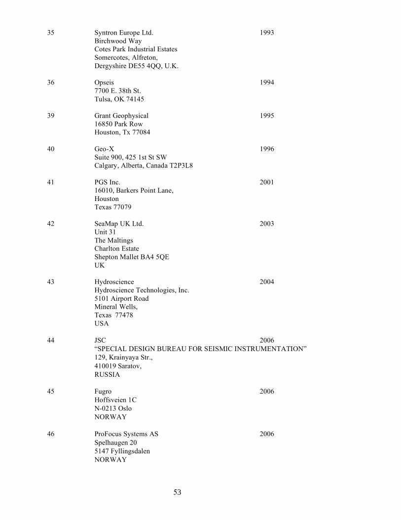
53
35 Syntron Europe Ltd. 1993 Birchwood Way Cotes Park Industrial Estates Somercotes, Alfreton, Dergyshire DE55 4QQ, U.K. 36 Opseis 1994 7700 E. 38th St. Tulsa, OK 74145 39 Grant Geophysical 1995 16850 Park Row Houston, Tx 77084 40 Geo-X 1996 Suite 900, 425 1st St SW Calgary, Alberta, Canada T2P3L8 41 PGS Inc. 2001
16010, Barkers Point Lane, Houston Texas 77079
42 SeaMap UK Ltd. 2003 Unit 31 The Maltings Charlton Estate Shepton Mallet BA4 5QE UK
43 Hydroscience 2004
Hydroscience Technologies, Inc. 5101 Airport Road Mineral Wells, Texas 77478 USA
44 JSC 2006 “SPECIAL DESIGN BUREAU FOR SEISMIC INSTRUMENTATION” 129, Krainyaya Str., 410019 Saratov, RUSSIA
45 Fugro 2006 Hoffsveien 1C N-0213 Oslo NORWAY 46 ProFocus Systems AS 2006 Spelhaugen 20 5147 Fyllingsdalen NORWAY
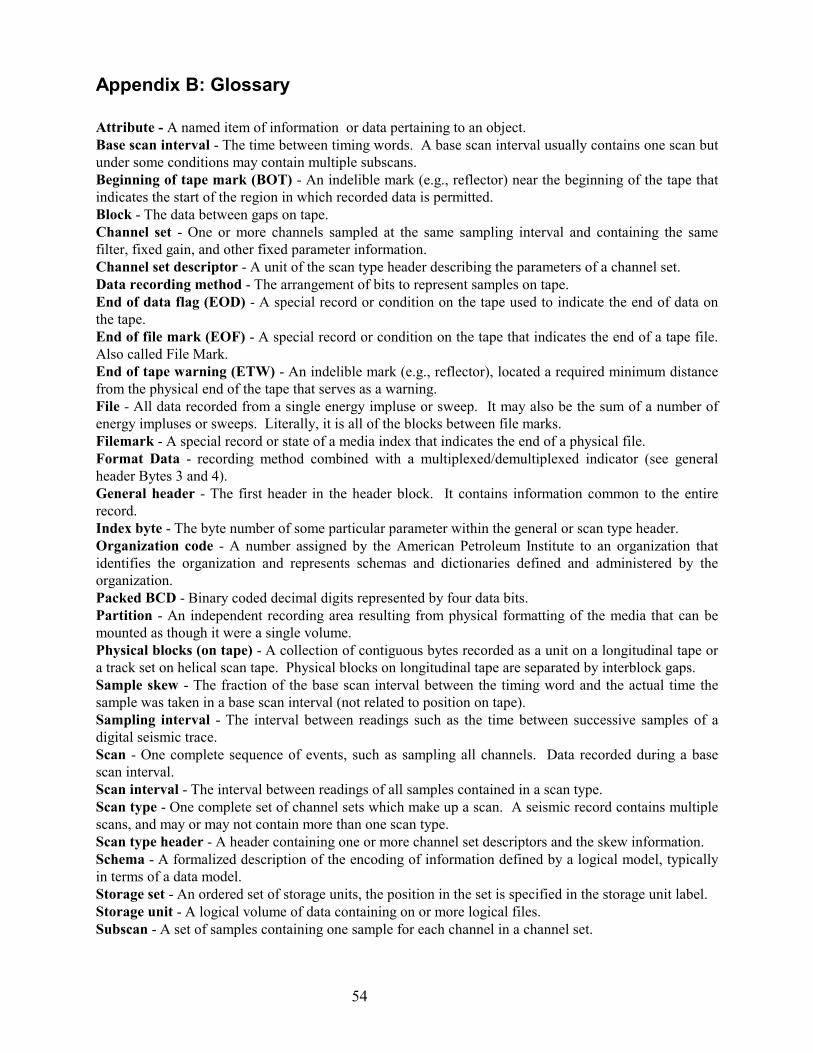
54
Appendix B: Glossary
Attribute - A named item of information or data pertaining to an object.Base scan interval - The time between timing words. A base scan interval usually contains one scan butunder some conditions may contain multiple subscans.Beginning of tape mark (BOT) - An indelible mark (e.g., reflector) near the beginning of the tape thatindicates the start of the region in which recorded data is permitted.Block - The data between gaps on tape.Channel set - One or more channels sampled at the same sampling interval and containing the samefilter, fixed gain, and other fixed parameter information.Channel set descriptor - A unit of the scan type header describing the parameters of a channel set.Data recording method - The arrangement of bits to represent samples on tape.End of data flag (EOD) - A special record or condition on the tape used to indicate the end of data onthe tape.End of file mark (EOF) - A special record or condition on the tape that indicates the end of a tape file.Also called File Mark.End of tape warning (ETW) - An indelible mark (e.g., reflector), located a required minimum distancefrom the physical end of the tape that serves as a warning.File - All data recorded from a single energy impluse or sweep. It may also be the sum of a number ofenergy impluses or sweeps. Literally, it is all of the blocks between file marks.Filemark - A special record or state of a media index that indicates the end of a physical file.Format Data - recording method combined with a multiplexed/demultiplexed indicator (see generalheader Bytes 3 and 4).General header - The first header in the header block. It contains information common to the entirerecord.Index byte - The byte number of some particular parameter within the general or scan type header.Organization code - A number assigned by the American Petroleum Institute to an organization thatidentifies the organization and represents schemas and dictionaries defined and administered by theorganization.Packed BCD - Binary coded decimal digits represented by four data bits.Partition - An independent recording area resulting from physical formatting of the media that can bemounted as though it were a single volume.Physical blocks (on tape) - A collection of contiguous bytes recorded as a unit on a longitudinal tape ora track set on helical scan tape. Physical blocks on longitudinal tape are separated by interblock gaps.Sample skew - The fraction of the base scan interval between the timing word and the actual time thesample was taken in a base scan interval (not related to position on tape).Sampling interval - The interval between readings such as the time between successive samples of adigital seismic trace.Scan - One complete sequence of events, such as sampling all channels. Data recorded during a basescan interval.Scan interval - The interval between readings of all samples contained in a scan type.Scan type - One complete set of channel sets which make up a scan. A seismic record contains multiplescans, and may or may not contain more than one scan type.Scan type header - A header containing one or more channel set descriptors and the skew information.Schema - A formalized description of the encoding of information defined by a logical model, typicallyin terms of a data model.Storage set - An ordered set of storage units, the position in the set is specified in the storage unit label.Storage unit - A logical volume of data containing on or more logical files.Subscan - A set of samples containing one sample for each channel in a channel set.

55
Tape file - Is the data contained between two File Marks or between an File Mark at its beginning and anEOD at its end. A typical implementation of EOD is an empty tape file, i.e., two consecutive File Marks.Some systems implement EOD as two or more (possibly many) File Marks.Tape record - A sequence of data bytes treated as a unit by the tape I/O subsystem. The applicationprovides the number of bytes in the tape record when writing and is returned the number of bytes in thetape record when reading. A tape record has an identifiable beginning on the tape, which need not be onthe boundary of a physical block, and which is locatable by the tape I/O subsystem.Time break window - Time interval in which time break is expected. If time break does not occur bythe end of the window, internal time break is generated.Trace - A record of one seismic channel within a scan type. A collection of a sequential set of pointsfrom one seismic channel.Trace block - A block containing the data of one trace or a part of a trace with constant parameters.
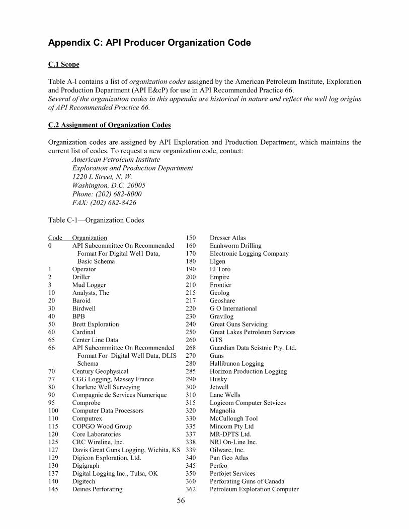
56
Appendix C: API Producer Organization Code
C.1 Scope
Table A-l contains a list of organization codes assigned by the American Petroleum Institute, Explorationand Production Department (API E&cP) for use in API Recommended Practice 66.Several of the organization codes in this appendix are historical in nature and reflect the well log originsof API Recommended Practice 66.
C.2 Assignment of Organization Codes
Organization codes are assigned by API Exploration and Production Department, which maintains thecurrent list of codes. To request a new organization code, contact:
American Petroleum InstituteExploration and Production Department1220 L Street, N. W.Washington, D.C. 20005Phone: (202) 682-8000FAX: (202) 682-8426
Table C-1—Organization Codes
Code Organization0 API Subcommittee On Recommended Format For Digital Wel1 Data,
Basic Schema1 Operator2 Driller3 Mud Logger10 Analysts, The20 Baroid30 Birdwell40 BPB50 Brett Exploration60 Cardinal65 Center Line Data66 API Subcommittee On Recommended
Format For Digital Well Data, DLIS Schema
70 Century Geophysical77 CGG Logging, Massey France80 Charlene Well Surveying90 Compagnie de Services Numerique95 Comprobe100 Computer Data Processors110 Computrex115 COPGO Wood Group120 Core Laboratories125 CRC Wireline, Inc.127 Davis Great Guns Logging, Wichita, KS129 Digicon Exploration, Ltd.130 Digigraph137 Digital Logging Inc., Tulsa, OK140 Digitech145 Deines Perforating
150 Dresser Atlas160 Eanhworm Drilling170 Electronic Logging Company180 Elgen190 El Toro200 Empire210 Frontier215 Geolog217 Geoshare220 G O International230 Gravilog240 Great Guns Servicing250 Great Lakes Petroleum Services260 GTS268 Guardian Data Seistnic Pty. Ltd.270 Guns280 Hallibunon Logging285 Horizon Production Logging290 Husky300 Jetwell310 Lane Wells315 Logicom Computer Setvices320 Magnolia330 McCullough Tool335 Mincom Pty Ltd337 MR-DPTS Ltd.338 NRI On-Line Inc.339 Oilware, Inc.340 Pan Geo Atlas345 Perfco350 Perfojet Services360 Perforating Guns of Canada362 Petroleum Exploration Computer

57
Consultants, Ltd.366 Phillips Petroleum Company370 Petroleum Information380 Petrophysics390 Pioneer395 QC. Data Collectors400 Ram Guns410 Riley's Datashare420 Roke430 Sand Surveys440 Schlumberger450 Scientific Software460 Seismograph Service462 SEGDEF463 SEG Technical Standards High Density
Media Format Subcommittee
464 Shell Service Co.465 Stratigraphic Systems, Inc.470 Triangle480 Welex490 Well Reconnaissance495 Wellsite Information Transfer Specification
(WITS)500 Well Surveys510 Western Westronics520 Winters525 Wireline530 Wireline Electronics540 Worth Well560 Z & S Consultants Limited999 Reserved for local schemes1000 Petrotechnical Open Software
.
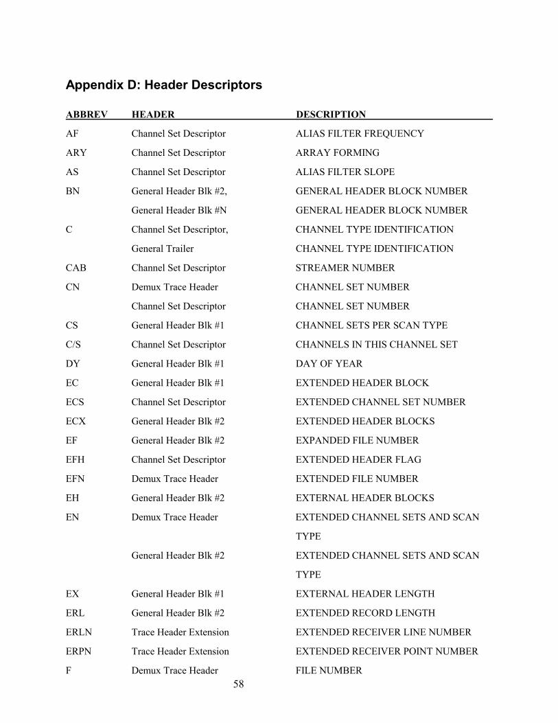
58
Appendix D: Header Descriptors
ABBREV HEADER DESCRIPTION
AF Channel Set Descriptor ALIAS FILTER FREQUENCY
ARY Channel Set Descriptor ARRAY FORMING
AS Channel Set Descriptor ALIAS FILTER SLOPE
BN General Header Blk #2, GENERAL HEADER BLOCK NUMBER
General Header Blk #N GENERAL HEADER BLOCK NUMBER
C Channel Set Descriptor, CHANNEL TYPE IDENTIFICATION
General Trailer CHANNEL TYPE IDENTIFICATION
CAB Channel Set Descriptor STREAMER NUMBER
CN Demux Trace Header CHANNEL SET NUMBER
Channel Set Descriptor CHANNEL SET NUMBER
CS General Header Blk #1 CHANNEL SETS PER SCAN TYPE
C/S Channel Set Descriptor CHANNELS IN THIS CHANNEL SET
DY General Header Blk #1 DAY OF YEAR
EC General Header Blk #1 EXTENDED HEADER BLOCK
ECS Channel Set Descriptor EXTENDED CHANNEL SET NUMBER
ECX General Header Blk #2 EXTENDED HEADER BLOCKS
EF General Header Blk #2 EXPANDED FILE NUMBER
EFH Channel Set Descriptor EXTENDED HEADER FLAG
EFN Demux Trace Header EXTENDED FILE NUMBER
EH General Header Blk #2 EXTERNAL HEADER BLOCKS
EN Demux Trace Header EXTENDED CHANNEL SETS AND SCAN
TYPE
General Header Blk #2 EXTENDED CHANNEL SETS AND SCAN
TYPE
EX General Header Blk #1 EXTERNAL HEADER LENGTH
ERL General Header Blk #2 EXTENDED RECORD LENGTH
ERLN Trace Header Extension EXTENDED RECEIVER LINE NUMBER
ERPN Trace Header Extension EXTENDED RECEIVER POINT NUMBER
F Demux Trace Header FILE NUMBER
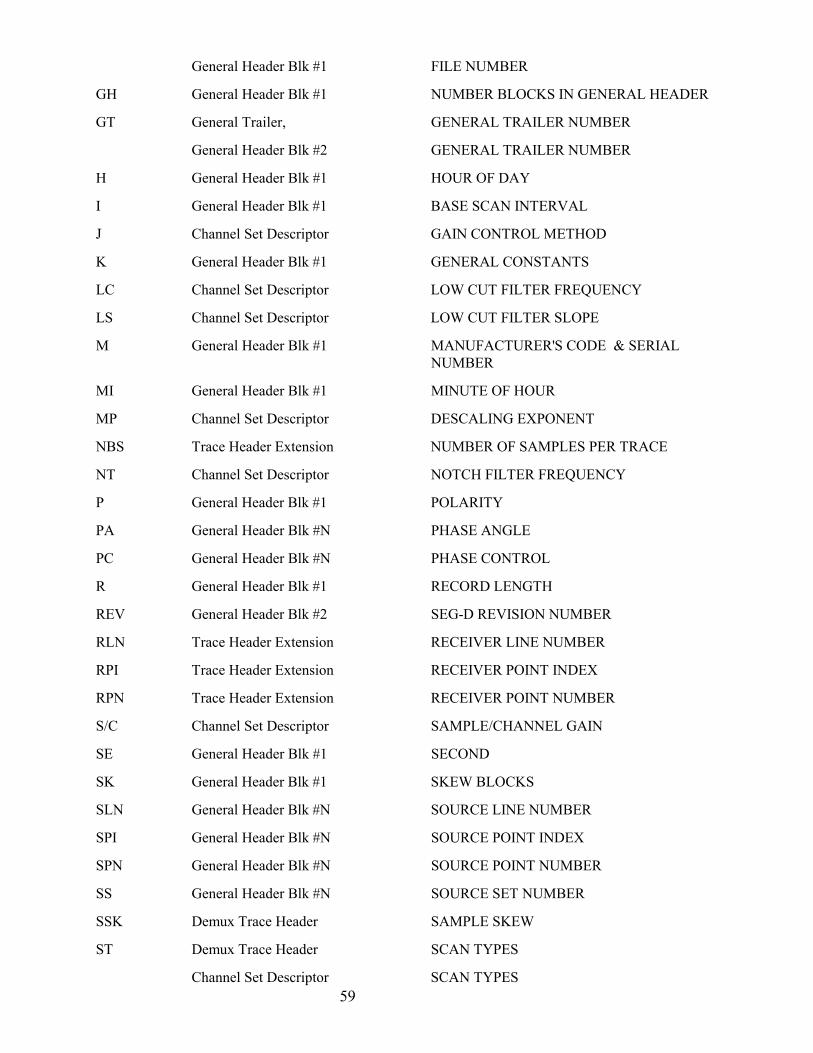
59
General Header Blk #1 FILE NUMBER
GH General Header Blk #1 NUMBER BLOCKS IN GENERAL HEADER
GT General Trailer, GENERAL TRAILER NUMBER
General Header Blk #2 GENERAL TRAILER NUMBER
H General Header Blk #1 HOUR OF DAY
I General Header Blk #1 BASE SCAN INTERVAL
J Channel Set Descriptor GAIN CONTROL METHOD
K General Header Blk #1 GENERAL CONSTANTS
LC Channel Set Descriptor LOW CUT FILTER FREQUENCY
LS Channel Set Descriptor LOW CUT FILTER SLOPE
M General Header Blk #1 MANUFACTURER'S CODE & SERIAL NUMBER
MI General Header Blk #1 MINUTE OF HOUR
MP Channel Set Descriptor DESCALING EXPONENT
NBS Trace Header Extension NUMBER OF SAMPLES PER TRACE
NT Channel Set Descriptor NOTCH FILTER FREQUENCY
P General Header Blk #1 POLARITY
PA General Header Blk #N PHASE ANGLE
PC General Header Blk #N PHASE CONTROL
R General Header Blk #1 RECORD LENGTH
REV General Header Blk #2 SEG-D REVISION NUMBER
RLN Trace Header Extension RECEIVER LINE NUMBER
RPI Trace Header Extension RECEIVER POINT INDEX
RPN Trace Header Extension RECEIVER POINT NUMBER
S/C Channel Set Descriptor SAMPLE/CHANNEL GAIN
SE General Header Blk #1 SECOND
SK General Header Blk #1 SKEW BLOCKS
SLN General Header Blk #N SOURCE LINE NUMBER
SPI General Header Blk #N SOURCE POINT INDEX
SPN General Header Blk #N SOURCE POINT NUMBER
SS General Header Blk #N SOURCE SET NUMBER
SSK Demux Trace Header SAMPLE SKEW
ST Demux Trace Header SCAN TYPES
Channel Set Descriptor SCAN TYPES

60
ST/R General Header Blk #1 SCAN TYPES PER RECORD
T Demux Trace Header FIRST TIMING WORD
TE Channel Set Descriptor CHANNEL SET END TIME
TF Channel Set Descriptor CHANNEL SET START TIME
THE Demux Trace Header TRACE HEADER EXTENSIONS
TN Demux Trace Header TRACE NUMBER
TR Demux Trace Header TRACE EDIT
TW Demux Trace Header TIME BREAK WINDOW
V General Header Blk #N TYPE VIBRATOR
VS Channel Set Descriptor VERTICAL STACK
Y General Header Blk #1 FORMAT CODE
YR General Header Blk #1 YEAR
Z General Header Blk #1 RECORD TYPE

61
Appendix E: Examples and Calculations
E.1 Samples per scan type
S S C Scs
/ /= ×∑ 21
s/c
whereS/S = samples per scan typeC/S = channels in this channel set (channel set descriptor Bytes 9 and 10)2s/c = samples per channel (in this channel set) (channel set descriptor Byte 12)CS = number of channel sets in this scan type (general header Byte 29)
For example, for a 2-msec base scan interval with 4 auxiliary channels at 2 msec, 96 channels at 2 msecand 12 channels at ½ msec. There are three channel sets, so CS = 3.
S/S = C/S x 2s/c + C/S x 2s/c + . . . cs = 1 cs = 2
S/S = 4 x 1 + 96 x 1 + 12 x 4S/S = 4 + 96 + 48 = 148
Note that all scan types must have the same number of data samples.
E.2 Skew fields per scan type
SK = S S/32
(If the quotient is not a whole number, round up to the next largest whole number)
whereSK = skew fields (of 32 bytes each) per scan type (general header Byte 30)S/S = samples per scan (Appendix E1)
Substituting for S/S from Appendix E.1:
SK C SCS
= ×∑132
21
/ s/c
(If the quotient is not a whole number, round up to the next largest whole number.)where
CS = the number of channel sets in each scan type (general header Byte 29)C/S = channels in this channel set (channel set descriptor Bytes 9 and 10)2s/c = samples per channel in this channel set (channel set descriptor Byte 12).
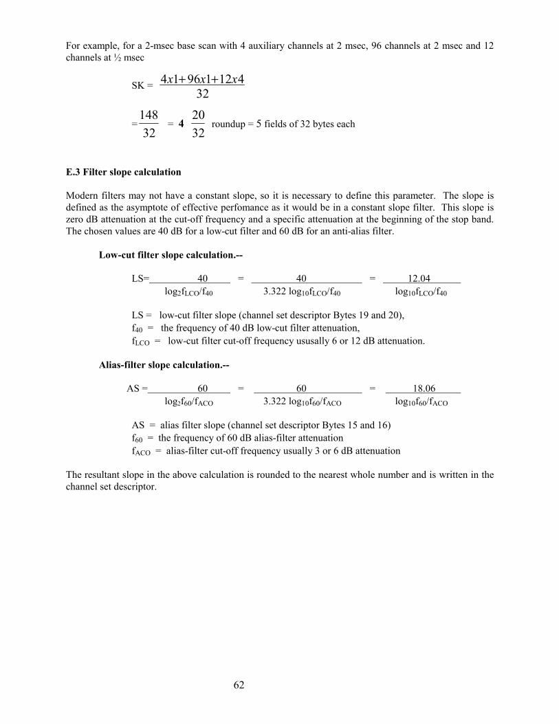
62
For example, for a 2-msec base scan with 4 auxiliary channels at 2 msec, 96 channels at 2 msec and 12channels at ½ msec
SK = 4 1 96 1 12 432
x x x+ +
=14832
= 4 2032
roundup = 5 fields of 32 bytes each
E.3 Filter slope calculation
Modern filters may not have a constant slope, so it is necessary to define this parameter. The slope isdefined as the asymptote of effective perfomance as it would be in a constant slope filter. This slope iszero dB attenuation at the cut-off frequency and a specific attenuation at the beginning of the stop band.The chosen values are 40 dB for a low-cut filter and 60 dB for an anti-alias filter.
Low-cut filter slope calculation.--
LS= 40 = 40 = 12.04 log2fLCO/f40 3.322 log10fLCO/f40 log10fLCO/f40
LS = low-cut filter slope (channel set descriptor Bytes 19 and 20),f40 = the frequency of 40 dB low-cut filter attenuation,fLCO = low-cut filter cut-off frequency ususally 6 or 12 dB attenuation.
Alias-filter slope calculation.--
AS = 60 = 60 = 18.06 log2f60/fACO 3.322 log10f60/fACO log10f60/fACO
AS = alias filter slope (channel set descriptor Bytes 15 and 16)f60 = the frequency of 60 dB alias-filter attenuationfACO = alias-filter cut-off frequency usually 3 or 6 dB attenuation
The resultant slope in the above calculation is rounded to the nearest whole number and is written in thechannel set descriptor.

63
Appendix F: Maximum Block Sizes
The table below indicates the maximum allowable block size for accepted types of media. It is expectedthat this table will need to be updated approximately once per year.
Device Type Maximum Block Size
3480 128 Kilobytes
3490, 3490E 256 Kilobytes
3590 512 Kilobytes
DST 1,199,840 Bytes
Redwood 256 Kilobytes
1/2” Round Tape 64 Kilobytes
Kilobyte is defined as 1024 bytes