Embed Size (px)
Citation preview

Security in Delay Tolerant Networks
by
Haojin Zhu
A thesis
presented to the University of Waterloo
in fulfillment of the
thesis requirement for the degree of
Doctor of Philosophy
in
Electrical and Computer Engineering
Waterloo, Ontario, Canada, 2009
c©Haojin Zhu 2009

I hereby declare that I am the sole author of this thesis. This is a true copy of the thesis,
including any required final revisions, as accepted by my examiners.
I understand that my thesis may be made electronically available to the public.
ii
Abstract
Delay- and Disruption-tolerant wireless networks (DTN), or opportunistic networks, rep-
resent a class of networks where continuous end-to-end connectivity may not be possible.
DTN is a well recognized area in networking research and has attracted extensive atten-
tions from both network designers and application developers. Applications of this emergent
communication paradigm are wide ranging and include sensor networks using scheduled in-
termittent connectivity, vehicular DTNs for dissemination of location-dependent information
(e.g., local ads, traffic reports, parking information, etc.), pocket-switched networks to allow
humans to communicate without network infrastructure, and underwater acoustic networks
with moderate delays and frequent interruptions due to environmental factors, etc.
Security is one of the main barriers to wide-scale deployment of DTNs, but has gained
little attention so far. On the one hand, similar to traditional mobile ad hoc networks, the
open channel and multi-hop transmission have made DTNs vulnerable to various security
threats, such as message modification/injection attack or unauthorized access and utilization
of DTN resources. On the other hand, the unique security characteristics of DTNs includ-
ing: long round-trip delay, frequent disconnectivity, fragmentation, opportunistic routing as
well as limited computational and storage capability, make the existing security protocols de-
signed for the conventional ad hoc networks unsuitable for DTNs. Therefore, a series of new
security protocols are highly desired to meet stringent security and efficiency requirements
for securing DTNs.
In this research, we focus on three fundamental security issues in DTNs: efficient DTN
message (or bundle) authentication, which is a critical security service for DTN security;
incentive issue, which targets at stimulating selfish nodes to forward data for others; and
iii
certificate revocation issue, which is an important part of public key management and serves
the foundation of any DTN security protocols. We have made the following contributions:
First of all, the unique “store-carry-and-forward” transmission characteristic of DTNs im-
plies that bundles from distinct/common senders may opportunistically be buffered at some
common intermediate nodes. Such a “buffering” characteristic distinguishes DTN from any
other traditional wireless networks, for which intermediate cache is not supported. To ex-
ploit such buffering opportunities, we propose an Opportunistic Batch Bundle Authentica-
tion Scheme (OBBA) to dramatically reduce the bundle authentication cost by seamlessly
integrating identity-based batch signatures and Merkle tree techniques.
Secondly, we propose a secure multi-layer credit based incentive scheme to stimulate
bundle forwarding cooperation among DTNs nodes. The proposed scheme can be imple-
mented in a fully distributed manner to thwart various attacks without relying on any tamper-
proof hardware. In addition, we introduce several efficiency-optimization techniques to im-
prove the overall efficiency by exploiting the unique characteristics of DTNs.
Lastly, we propose a storage-efficient public key certificate validation method. Our pro-
posed scheme exploits the opportunistic propagation to transmit Certificate Revocation List
(CRL) list while taking advantage of bloom filter technique to reduce the required buffer size.
We also discuss how to take advantage of cooperative checking to minimize false positive rate
and storage consumption.
For each research issue, detailed simulation results in terms of computational time, trans-
mission overhead and power consumption, are given to validate the efficiency and effective-
ness of the proposed security solutions.
iv

Acknowledgments
I would like to express my deepest gratitude to Professor Xuemin (Sherman) Shen, my advi-
sor. I thank you for your continuing guidance and support during my four years of research.
Your sharp sense of research direction, great enthusiasm, and strong belief in the potential of
this research has been a tremendous force for the completion of this work. I have learned so
many things from you, including the research process, writing papers, giving talks, and many
more. Most importantly, I thank you for encouraging me in each step of my growing path.
Your strong belief in me and continuous encouragement have made this research such an
exciting experience that our collaboration finally produces something that we are both proud
of.
This thesis would not have been possible without the assistance of many people. I would
also like to express my extreme appreciation to my thesis committee members: Professor Yi
Pan, Professor Raouf Boutaba, Professor Liang-Liang Xie and Professor Sagar Naik. They
contributed their precious time to read my thesis, and provided valuable suggestions and
comments that helped to improve the quality of this thesis.
I would like to express my great gratitude to Professor Pin-Han Ho and Professor Zhenfu
Cao, who have made invaluable suggestions in many aspects of my previous research. I
would also like to thank my colleagues and friends at Security Discussion Group of BBCR
Lab. My discussions with Xiaodong Lin, Rongxing Lu, Yanfei Fan, Minghui Shi, Chenxi
Zhang, Xiaoting Sun, Jiming Chen, Yixin Jiang and Yipin Sun gave me many inspirations. I
feel so fortunate to work with many wonderful people in BBCR Lab, such as Bin Lin, Bong
Choi, Ho Ting Cheng and more. I thank them all.
There are many other people whose names are not mentioned here. It does not mean that
I have forgotten you or your help. It is a privilege for me to work and share life with so many
v

bright and energetic people. Your talent and friendship have made Waterloo such a great
place to live.
I would never get this far without the support of my parents. Thank you for always
believing in me and supporting me. Your love and encouragement have been and will always
be a great source of inspiration in my life.
Suguo, my dear wife, you are always my strength. I owe my deepest gratitude to you
for your infinite patience that accompanied me along this long journey. Your love pulled me
through many difficult times. I look forward to our bright future in Shanghai. I love you.
vi
Contents
List of Tables xii
List of Figures xiii
List of Abbreviations xv
1 Introduction 1
1.1 DTN Motivating Application Scenarios . . . . . . . . . . . . . . . . . . . . 2
1.1.1 Service-Oriented Vehicular Networks and Vehicular DTN . . . . . . 2
1.1.2 Pocket Switched Networks (PSNs) . . . . . . . . . . . . . . . . . . . 3
1.2 Research Issues in DTNs: Non-Security Aspects . . . . . . . . . . . . . . . 4
1.3 DTN Security: Research Motivations and Contributions . . . . . . . . . . . 6
1.3.1 Motivations . . . . . . . . . . . . . . . . . . . . . . . . . . . . . . . 6
1.3.2 Contributions . . . . . . . . . . . . . . . . . . . . . . . . . . . . . . 7
1.4 Outline of This Thesis . . . . . . . . . . . . . . . . . . . . . . . . . . . . . 8
2 DTN Security: Threat, Requirements, Characteristics and Challenges 10
2.1 DTN Security Threat . . . . . . . . . . . . . . . . . . . . . . . . . . . . . . 10
2.2 DTN Security Requirements . . . . . . . . . . . . . . . . . . . . . . . . . . 11
vii
2.2.1 Authentication . . . . . . . . . . . . . . . . . . . . . . . . . . . . . 11
2.2.2 Confidentiality . . . . . . . . . . . . . . . . . . . . . . . . . . . . . 12
2.2.3 Integrity . . . . . . . . . . . . . . . . . . . . . . . . . . . . . . . . . 12
2.2.4 Privacy/Anonymity . . . . . . . . . . . . . . . . . . . . . . . . . . . 12
2.3 DTN Security Characteristics . . . . . . . . . . . . . . . . . . . . . . . . . . 13
2.3.1 Lack of End-to-end Connectivity: . . . . . . . . . . . . . . . . . . . 13
2.3.2 Fragmentation: . . . . . . . . . . . . . . . . . . . . . . . . . . . . . 13
2.3.3 Resource-scarcity: . . . . . . . . . . . . . . . . . . . . . . . . . . . 14
2.3.4 Bundle Accumulation: . . . . . . . . . . . . . . . . . . . . . . . . . 14
2.4 Bundle Security Protocol Specification . . . . . . . . . . . . . . . . . . . . . 15
2.4.1 Security Blocks . . . . . . . . . . . . . . . . . . . . . . . . . . . . . 15
2.4.2 Bundle Authentication Block . . . . . . . . . . . . . . . . . . . . . . 16
2.4.3 Payload Integrity Block (PIB) . . . . . . . . . . . . . . . . . . . . . 17
2.4.4 Payload Confidentiality Block (PCB) . . . . . . . . . . . . . . . . . 18
2.4.5 Abstract Security Block (ASB) . . . . . . . . . . . . . . . . . . . . . 18
2.4.6 More Discussion on BAB and PIB . . . . . . . . . . . . . . . . . . . 21
2.5 Identified Research Challenges . . . . . . . . . . . . . . . . . . . . . . . . . 22
2.5.1 Tradeoff between the Security and Performance . . . . . . . . . . . . 22
2.5.2 Thwarting Selfish Behavior . . . . . . . . . . . . . . . . . . . . . . 23
2.5.3 Public Key Management/Revocation Issue . . . . . . . . . . . . . . . 23
2.6 Summary . . . . . . . . . . . . . . . . . . . . . . . . . . . . . . . . . . . . 23
3 An Opportunistic Batch Bundle Authentication Scheme for DTNs 24
3.1 Preliminaries . . . . . . . . . . . . . . . . . . . . . . . . . . . . . . . . . . 27
3.1.1 DTN Security and Bundle Authentication . . . . . . . . . . . . . . . 27
viii
3.1.2 Identity based Cryptography . . . . . . . . . . . . . . . . . . . . . . 29
3.2 Models and Design Goals . . . . . . . . . . . . . . . . . . . . . . . . . . . . 29
3.2.1 System Model . . . . . . . . . . . . . . . . . . . . . . . . . . . . . 30
3.2.2 Adversary Model . . . . . . . . . . . . . . . . . . . . . . . . . . . . 30
3.2.3 Design Goals . . . . . . . . . . . . . . . . . . . . . . . . . . . . . . 30
3.3 The Proposed Scheme . . . . . . . . . . . . . . . . . . . . . . . . . . . . . . 31
3.3.1 The Basic OBBA . . . . . . . . . . . . . . . . . . . . . . . . . . . . 31
3.3.2 Utilizing Fragment Authentication Tree (FAT) to Achieve Efficient
Fragment Authentication . . . . . . . . . . . . . . . . . . . . . . . . 36
3.3.3 An Advanced Scheme: A Hybrid Batch Bundle Authentication Scheme
(OBBA-FAT) . . . . . . . . . . . . . . . . . . . . . . . . . . . . . . 41
3.4 Simulations and Performance Evaluation . . . . . . . . . . . . . . . . . . . . 42
3.4.1 Bundle Size Distribution . . . . . . . . . . . . . . . . . . . . . . . . 44
3.4.2 Computational Cost . . . . . . . . . . . . . . . . . . . . . . . . . . 47
3.4.3 Transmission Overhead . . . . . . . . . . . . . . . . . . . . . . . . . 48
3.4.4 Energy Consumption . . . . . . . . . . . . . . . . . . . . . . . . . . 50
3.5 Summary . . . . . . . . . . . . . . . . . . . . . . . . . . . . . . . . . . . . 50
4 A Secure Multi-Layer Credit-based Incentive Scheme for DTNs 52
4.1 Related Work . . . . . . . . . . . . . . . . . . . . . . . . . . . . . . . . . . 55
4.2 System Model and Design Goals . . . . . . . . . . . . . . . . . . . . . . . . 56
4.2.1 Network Model . . . . . . . . . . . . . . . . . . . . . . . . . . . . . 57
4.2.2 Data Forwarding Strategy . . . . . . . . . . . . . . . . . . . . . . . 57
4.2.3 Rewarding Model . . . . . . . . . . . . . . . . . . . . . . . . . . . . 58
4.2.4 Attack Model . . . . . . . . . . . . . . . . . . . . . . . . . . . . . . 59
ix
4.2.5 Design Goals . . . . . . . . . . . . . . . . . . . . . . . . . . . . . . 60
4.3 The Proposed SMART Scheme . . . . . . . . . . . . . . . . . . . . . . . . . 60
4.3.1 Pairing Technique . . . . . . . . . . . . . . . . . . . . . . . . . . . 60
4.3.2 The Overview of SMART . . . . . . . . . . . . . . . . . . . . . . . 61
4.3.3 The SMART Scheme . . . . . . . . . . . . . . . . . . . . . . . . . . 65
4.3.4 Efficiency Enhancement . . . . . . . . . . . . . . . . . . . . . . . . 68
4.4 Performance Evaluation . . . . . . . . . . . . . . . . . . . . . . . . . . . . . 71
4.4.1 Cryptographic Overhead Evaluation . . . . . . . . . . . . . . . . . . 71
4.4.2 Simulation . . . . . . . . . . . . . . . . . . . . . . . . . . . . . . . 73
4.5 Further Discussion . . . . . . . . . . . . . . . . . . . . . . . . . . . . . . . 82
4.5.1 Public Key Revocation in DTNs . . . . . . . . . . . . . . . . . . . . 83
4.5.2 Public Key Cryptography vs Identity-based Cryptography . . . . . . 83
4.6 Summary . . . . . . . . . . . . . . . . . . . . . . . . . . . . . . . . . . . . 84
5 Practical Public Key Management in DTNs with Cooperative CRL Caching 85
5.1 Preliminaries . . . . . . . . . . . . . . . . . . . . . . . . . . . . . . . . . . 86
5.1.1 Public Key Certificate Basics . . . . . . . . . . . . . . . . . . . . . . 86
5.1.2 Challenges of Public Key Management in DTNs . . . . . . . . . . . 90
5.1.3 Bloom Filter . . . . . . . . . . . . . . . . . . . . . . . . . . . . . . 91
5.2 A Basic CRL Distribution Scheme in DTNs . . . . . . . . . . . . . . . . . . 92
5.2.1 Network Model . . . . . . . . . . . . . . . . . . . . . . . . . . . . . 92
5.2.2 The Proposed Scheme . . . . . . . . . . . . . . . . . . . . . . . . . 92
5.3 An Advanced Bloom Filter based CRL Caching Scheme with Cooperative
Checking . . . . . . . . . . . . . . . . . . . . . . . . . . . . . . . . . . . . 95
5.4 Summary . . . . . . . . . . . . . . . . . . . . . . . . . . . . . . . . . . . . 96
x

6 Conclusions and Future Work 97
6.1 Contributions . . . . . . . . . . . . . . . . . . . . . . . . . . . . . . . . . . 97
6.2 Future Work . . . . . . . . . . . . . . . . . . . . . . . . . . . . . . . . . . . 98
6.2.1 Privacy Preserving Protocols . . . . . . . . . . . . . . . . . . . . . . 98
6.2.2 Reputation based Incentive Scheme . . . . . . . . . . . . . . . . . . 98
Bibliography 100
Author’s Publications 108
xi
List of Tables
3.1 Parameters for OBBA Simulations . . . . . . . . . . . . . . . . . . . . . . . 44
3.2 ECDSA and Pairing Computation Time . . . . . . . . . . . . . . . . . . . . 47
4.1 The Size of Each Component of Layered Coin(bytes) . . . . . . . . . . . . . 72
4.2 Cryptographic Operation’s Execution Time . . . . . . . . . . . . . . . . . . 73
4.3 Parameters for SMART Simulations . . . . . . . . . . . . . . . . . . . . . . 74
xii
List of Figures
1.1 An Example of Vehicular DTNs . . . . . . . . . . . . . . . . . . . . . . . . 4
2.1 Hop by Hop Authentication of Bundle Authentication Block . . . . . . . . . 16
2.2 Two Operation Mode (Hop-by-Hop/End-to-End) for Bundle Integrity Block . 17
2.3 Bundle Confidentiality Block . . . . . . . . . . . . . . . . . . . . . . . . . . 18
2.4 The Structure of An Abstract Security Block . . . . . . . . . . . . . . . . . . 19
2.5 The Structure of Ciphersuite Flags . . . . . . . . . . . . . . . . . . . . . . . 21
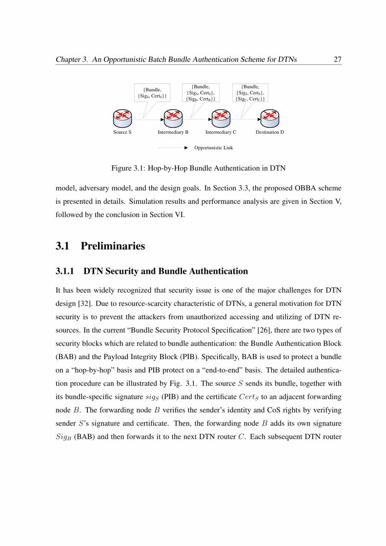
3.1 Hop-by-Hop Bundle Authentication in DTN . . . . . . . . . . . . . . . . . . 27
3.2 An Example of FAT Tree and Fragment 2’s Off Path Vertices . . . . . . . . . 38
3.3 An Example of Advanced OBBA-FAT Approach . . . . . . . . . . . . . . . 43
3.4 Batch Size Distribution in Normal Traffic . . . . . . . . . . . . . . . . . . . 45
3.5 Batch Size Distribution in 2x Network Traffic . . . . . . . . . . . . . . . . . 46
3.6 Batch Size Distribution in 2x Forwarding Copies . . . . . . . . . . . . . . . 46
3.7 Computational Cost Comparison between OBBA and ECDSA-IBA . . . . . 48
3.8 Transmission Overhead Comparison between OBBA and ECDSA-IBA . . . . 49
3.9 Energy Consumption Comparison between OBBA and ECDSA-IBA . . . . . 51
4.1 A Generalized Data Forwarding Strategy . . . . . . . . . . . . . . . . . . . . 58
xiii
4.2 An Example of Layered Coin for a Single Forwarding Path . . . . . . . . . . 63
4.3 The Probability of Existing at Least A Non-compromised Path under Differ-
ent nc . . . . . . . . . . . . . . . . . . . . . . . . . . . . . . . . . . . . . . 65
4.4 An Example of Merkle Tree Building . . . . . . . . . . . . . . . . . . . . . 71
4.5 Effect of Incentive Scheme . . . . . . . . . . . . . . . . . . . . . . . . . . . 75
4.6 Impact of Network Load on System Performance: Successful Delivery Ratio . 77
4.7 Impact of Network Load on System Performance: Average Latency . . . . . 78
4.8 Impact of Network Load on System Performance: Overhead Ratio . . . . . . 79
4.9 Impact of Forwarding Copy Number on System Performance: Delivery Ratio 80
4.10 Impact of Forwarding Copy Number on System Performance: Average Latency 81
4.11 Impact of Forwarding Copy Number on System Performance: Overhead Ratio 82
5.1 Impact of m/n on False Positive . . . . . . . . . . . . . . . . . . . . . . . . . 94
5.2 Impact of Hops on Public Key Certificate Validation . . . . . . . . . . . . . . 96
xiv
List of Abbreviations
AAA Authentication, Authorization and Accounting
AA Attribute Authority
ASB Abstract Security Block
BAB Bundle Authentication Block
CCW Cooperative Collision Warning
CRL Certificate Revocation List
CA Certificate Authorities
CDP CRL Distribution Point
CRT Certificate Revocation Tree
DTN Delay/disruption-tolerant network
DTNRG Delay Tolerant Networking Research Group
DSRC Dedicated Short Range Communication
DNS Domain Name System
DoS Denial of Service
FAT Fragment Authentication Tree
IBC Identity Based Cryptography
LANs Local Area Networks
xv
MAC Media Authentication Code
OBBA Opportunistic Batch Bundle Authentication
OCSP Online Certificate Status Protocol
PKI Public Key Infrastructure
PIB Payload Integrity Block
PCB Payload Confidentiality Block
PSNs Pocket-Switched Networks
RSU Roadside Units
SMART Secure Multi-Layer Credit-based Incentive
SW Spray and Wait routing
SWB Binary Spray and Wait
VANETs Vehicular Ad Hoc Networks
WSNs Wireless Sensor Networks
xvi
Chapter 1
Introduction
Wireless networks, whether cellular networks or wireless local area networks (LANs) have
rapidly become an indispensable part of our life. By now, the number of wireless phones has
superseded that of wired ones. Wireless LANs are routinely used by millions of nomadic
users. Wireless devices have become commonplace in offices, private homes, factories, and
hospitals. The widespread availability of miniature wireless devices such as PDAs, cellular
phones or laptops are one step towards making “ubiquitous access” a reality.
In addition to this pervasiveness, we are witnessing a change of network paradigm. Ini-
tially, wireless devices had limited or no programmability/mobility and were managed (and
secured) in a highly centralized fashion. Today, high-tier wireless end-systems are full-
fledged personal computers and take an increasing active role in the networking mechanisms.
In the extreme case of multi-hop ad hoc networks, each node functions not only as an end
user but also as a router forwarding packets to and from other nodes to enable multi-hop
communication. As a special kind of ad hoc networks, Delay/disruption-tolerant networks
(DTN) are receiving increasing attentions from both academia and industry.
The general field of DTN networking, as defined by the Delay Tolerant Networking Re-
search Group (DTNRG), is concerned with “ how to address the architectural and proto-
col design principles arising from the need to provide interoperable communications with
1

Security in Delay Tolerant Networks 2
and among extreme and performance-challenged environments where continuous end-to-end
connectivity cannot be assumed”. Application domains of DTNs include mobile Wireless
Sensor Networks (WSNs) for wildlife tracking [1, 2], underwater sensor networks [3, 4], dis-
aster relief team networks, networks for remote areas or rural areas in developing countries,
vehicular networks [5] and Pocket-Switched Networks (PSNs) [6, 7]. These networks are
subject to intermittent connectivity and disconnection of nodes due to limitations of power,
node mobility, sparse node density, and equipment failures. In the next section, we will take
vehicular DTN and PSNs as the examples to introduce DTNs in details.
1.1 DTN Motivating Application Scenarios
1.1.1 Service-Oriented Vehicular Networks and Vehicular DTN
Vehicular networks, also known as Vehicular Ad Hoc Networks (VANETs), are emerging as a
promising approach to increase road safety, efficiency and convenience [8]. Although the pri-
mary purpose of VANET is to enable communication-based automotive safety applications,
e.g., cooperative collision warning (CCW), the existing Dedicated Short Range Communica-
tion (DSRC) standard also provisions for a range of commercial applications thereby making
them more cost-effective. For example, Internet access has become part of our daily life and
there is a growing demand for accessing the Internet or information centers from vehicles.
Therefore, the roadside units (or RSUs) can be deployed every few miles along the highway
for users to download maps, traffic data and multimedia files. Vehicles can also use RSUs to
report real time traffic information and request location-based services such as finding restau-
rants, gas stations, or available parking space. Although 3G networks or satellite techniques
can be used to achieve this goal, RSUs have the advantage of low cost, easy deployment,
and high bandwidth. We call this type of vehicular networks the Service-Oriented Vehicular
Networks, which are expected to provide clear customer benefit and motivate commercial
operators to invest on large-scale deployment of wireless infrastructures.

Chapter 1. Introduction 3
In service-oriented vehicular networks, the message transmission is delivered in a typical
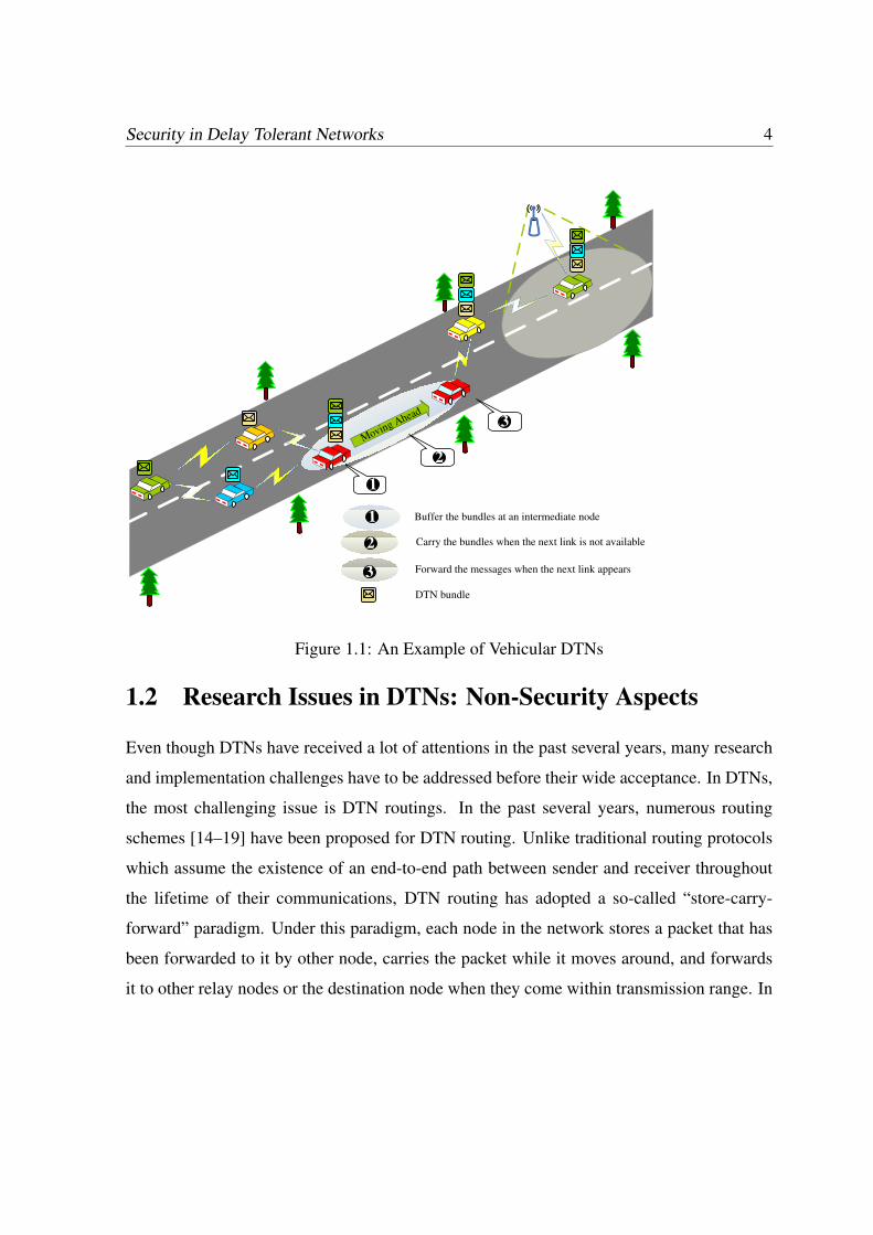
DTN method. As shown in Fig. 1.1, RSUs can serve as fixed Internet gateways along the
road to provide Internet access to vehicles. However, due to the limited transmission range
of a RSU, the remote vehicles may not connect to the RSU directly and thus have to rely
on intermediate vehicles to relay the packets. During the message relay process, complete
end-to-end paths may not exist in highly partitioned VANETs. Therefore, the intermediate
vehicles must buffer and forward messages opportunistically. Through buffer, carry and
forward, the message can eventually be delivered to the destination (e.g, RSU in Fig. 1.1)
even without an end-to-end connection for delay tolerant applications. Vehicular DTNs can
also be used to provide low cost service to remote villages and vehicular sensing platforms
such as CarTel for urban monitoring [9]. Similar to other DTN applications, in vehicular
DTNs, the in-transit messages (bundles) could be sent over an existing link, buffered at the
next hop until the next link in the path appears (e.g., a new vehicle moves in range), and
so on, until they reach their destinations. Such a message propagation process is usually
referred to as “store-carry-and-forward”.
1.1.2 Pocket Switched Networks (PSNs)
Another scenario in which DTN can be useful is in networking for devices carried by users
of mobile and portable devices. For example, mobile workers move between connectivity is-
lands (e.g., WiFi at home and work). Outside these islands, end-to-end connectivity becomes
expensive, slow, or simply unavailable. Moreover, many communication services rely on
access to centralized resources such as the DNS (or Domain Name System). That prevents,
for example, two users sitting beside each other from easily exchanging data. This situation
corresponds to individuals at conferences, around office spaces, and in social settings. Net-
works in these environments are examples of PSNs [6], in which both mobility and multi-hop
forwarding can be used to support communication.
Security in Delay Tolerant Networks 4
1
2
1
Buffer the bundles at an intermediate node
Carry the bundles when the next link is not available
3 Forward the messages when the next link appears
DTN bundle
Moving Ahead
2
3
Figure 1.1: An Example of Vehicular DTNs
1.2 Research Issues in DTNs: Non-Security Aspects
Even though DTNs have received a lot of attentions in the past several years, many research
and implementation challenges have to be addressed before their wide acceptance. In DTNs,
the most challenging issue is DTN routings. In the past several years, numerous routing
schemes [14–19] have been proposed for DTN routing. Unlike traditional routing protocols
which assume the existence of an end-to-end path between sender and receiver throughout
the lifetime of their communications, DTN routing has adopted a so-called “store-carry-
forward” paradigm. Under this paradigm, each node in the network stores a packet that has
been forwarded to it by other node, carries the packet while it moves around, and forwards
it to other relay nodes or the destination node when they come within transmission range. In
Chapter 1. Introduction 5
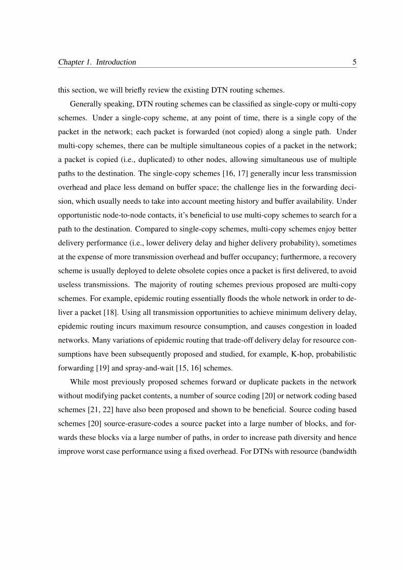
this section, we will briefly review the existing DTN routing schemes.
Generally speaking, DTN routing schemes can be classified as single-copy or multi-copy
schemes. Under a single-copy scheme, at any point of time, there is a single copy of the
packet in the network; each packet is forwarded (not copied) along a single path. Under
multi-copy schemes, there can be multiple simultaneous copies of a packet in the network;
a packet is copied (i.e., duplicated) to other nodes, allowing simultaneous use of multiple
paths to the destination. The single-copy schemes [16, 17] generally incur less transmission
overhead and place less demand on buffer space; the challenge lies in the forwarding deci-
sion, which usually needs to take into account meeting history and buffer availability. Under
opportunistic node-to-node contacts, it’s beneficial to use multi-copy schemes to search for a
path to the destination. Compared to single-copy schemes, multi-copy schemes enjoy better
delivery performance (i.e., lower delivery delay and higher delivery probability), sometimes
at the expense of more transmission overhead and buffer occupancy; furthermore, a recovery
scheme is usually deployed to delete obsolete copies once a packet is first delivered, to avoid
useless transmissions. The majority of routing schemes previous proposed are multi-copy
schemes. For example, epidemic routing essentially floods the whole network in order to de-
liver a packet [18]. Using all transmission opportunities to achieve minimum delivery delay,
epidemic routing incurs maximum resource consumption, and causes congestion in loaded
networks. Many variations of epidemic routing that trade-off delivery delay for resource con-
sumptions have been subsequently proposed and studied, for example, K-hop, probabilistic
forwarding [19] and spray-and-wait [15, 16] schemes.
While most previously proposed schemes forward or duplicate packets in the network
without modifying packet contents, a number of source coding [20] or network coding based
schemes [21, 22] have also been proposed and shown to be beneficial. Source coding based
schemes [20] source-erasure-codes a source packet into a large number of blocks, and for-
wards these blocks via a large number of paths, in order to increase path diversity and hence
improve worst case performance using a fixed overhead. For DTNs with resource (bandwidth
Security in Delay Tolerant Networks 6
and buffer) constraints, Random Linear Coding (a special form of randomized network cod-
ing) based schemes are shown to improve block delivery delay versus transmissions overhead
trade-off due to its increased randomness [22].
Even though DTN routing is a major challenge for DTN research, there are also other
works which have studied DTNs from the point of view of power management [10], buffer
management [11] and capacity building through deploying static nodes [12] or specialized
mobile nodes [13]. However, until now there has not been much attention on the security
issues in DTNs.
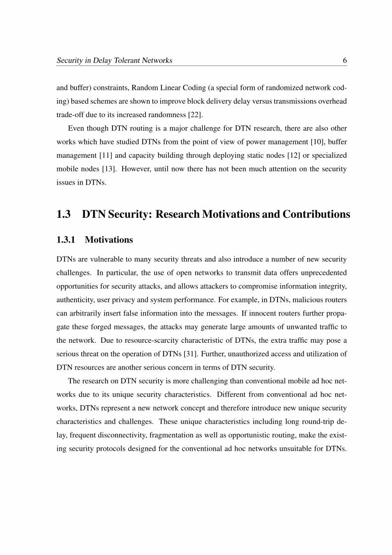
1.3 DTN Security: Research Motivations and Contributions
1.3.1 Motivations
DTNs are vulnerable to many security threats and also introduce a number of new security
challenges. In particular, the use of open networks to transmit data offers unprecedented
opportunities for security attacks, and allows attackers to compromise information integrity,
authenticity, user privacy and system performance. For example, in DTNs, malicious routers
can arbitrarily insert false information into the messages. If innocent routers further propa-
gate these forged messages, the attacks may generate large amounts of unwanted traffic to
the network. Due to resource-scarcity characteristic of DTNs, the extra traffic may pose a
serious threat on the operation of DTNs [31]. Further, unauthorized access and utilization of
DTN resources are another serious concern in terms of DTN security.
The research on DTN security is more challenging than conventional mobile ad hoc net-
works due to its unique security characteristics. Different from conventional ad hoc net-
works, DTNs represent a new network concept and therefore introduce new unique security
characteristics and challenges. These unique characteristics including long round-trip de-
lay, frequent disconnectivity, fragmentation as well as opportunistic routing, make the exist-
ing security protocols designed for the conventional ad hoc networks unsuitable for DTNs.
Chapter 1. Introduction 7
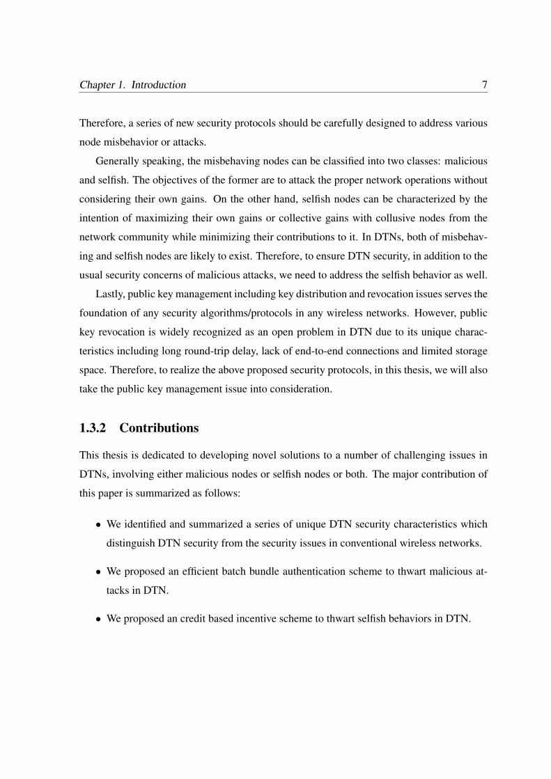
Therefore, a series of new security protocols should be carefully designed to address various
node misbehavior or attacks.
Generally speaking, the misbehaving nodes can be classified into two classes: malicious
and selfish. The objectives of the former are to attack the proper network operations without
considering their own gains. On the other hand, selfish nodes can be characterized by the
intention of maximizing their own gains or collective gains with collusive nodes from the
network community while minimizing their contributions to it. In DTNs, both of misbehav-
ing and selfish nodes are likely to exist. Therefore, to ensure DTN security, in addition to the
usual security concerns of malicious attacks, we need to address the selfish behavior as well.
Lastly, public key management including key distribution and revocation issues serves the
foundation of any security algorithms/protocols in any wireless networks. However, public
key revocation is widely recognized as an open problem in DTN due to its unique charac-
teristics including long round-trip delay, lack of end-to-end connections and limited storage
space. Therefore, to realize the above proposed security protocols, in this thesis, we will also
take the public key management issue into consideration.
1.3.2 Contributions
This thesis is dedicated to developing novel solutions to a number of challenging issues in
DTNs, involving either malicious nodes or selfish nodes or both. The major contribution of
this paper is summarized as follows:
• We identified and summarized a series of unique DTN security characteristics which
distinguish DTN security from the security issues in conventional wireless networks.
• We proposed an efficient batch bundle authentication scheme to thwart malicious at-
tacks in DTN.
• We proposed an credit based incentive scheme to thwart selfish behaviors in DTN.
Security in Delay Tolerant Networks 8
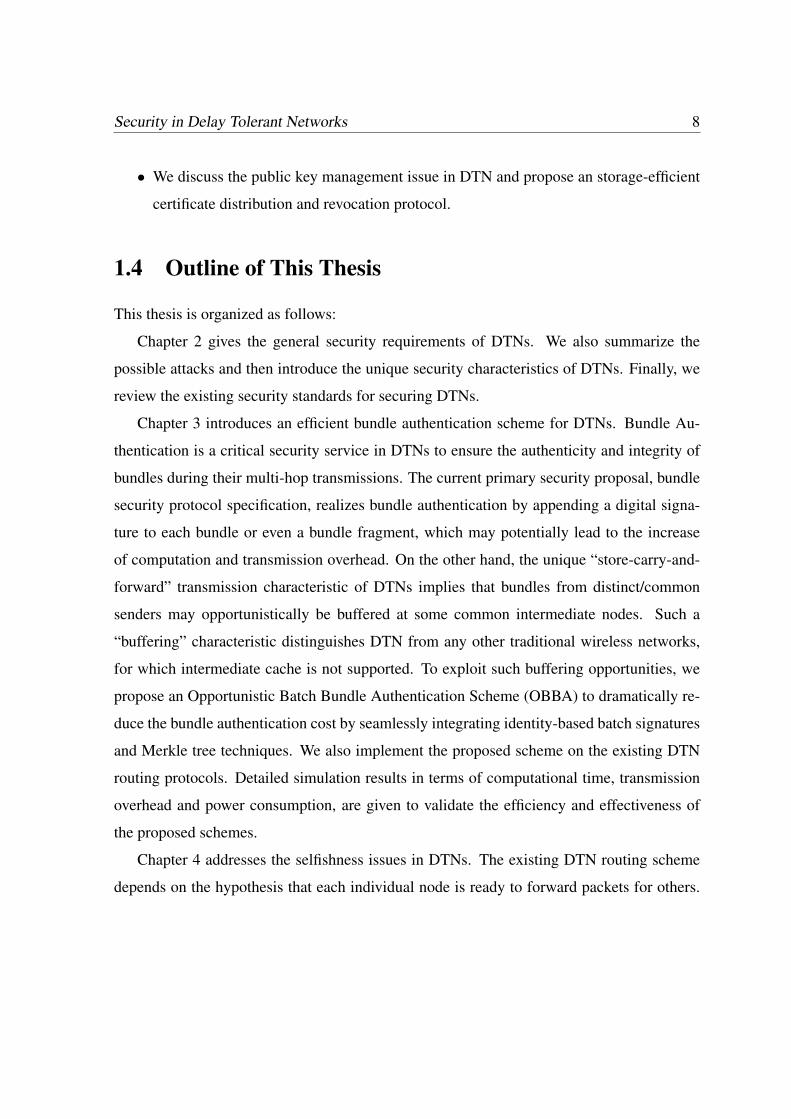
• We discuss the public key management issue in DTN and propose an storage-efficient
certificate distribution and revocation protocol.
1.4 Outline of This Thesis
This thesis is organized as follows:
Chapter 2 gives the general security requirements of DTNs. We also summarize the
possible attacks and then introduce the unique security characteristics of DTNs. Finally, we
review the existing security standards for securing DTNs.
Chapter 3 introduces an efficient bundle authentication scheme for DTNs. Bundle Au-
thentication is a critical security service in DTNs to ensure the authenticity and integrity of
bundles during their multi-hop transmissions. The current primary security proposal, bundle
security protocol specification, realizes bundle authentication by appending a digital signa-
ture to each bundle or even a bundle fragment, which may potentially lead to the increase
of computation and transmission overhead. On the other hand, the unique “store-carry-and-
forward” transmission characteristic of DTNs implies that bundles from distinct/common
senders may opportunistically be buffered at some common intermediate nodes. Such a
“buffering” characteristic distinguishes DTN from any other traditional wireless networks,
for which intermediate cache is not supported. To exploit such buffering opportunities, we
propose an Opportunistic Batch Bundle Authentication Scheme (OBBA) to dramatically re-
duce the bundle authentication cost by seamlessly integrating identity-based batch signatures
and Merkle tree techniques. We also implement the proposed scheme on the existing DTN
routing protocols. Detailed simulation results in terms of computational time, transmission
overhead and power consumption, are given to validate the efficiency and effectiveness of
the proposed schemes.
Chapter 4 addresses the selfishness issues in DTNs. The existing DTN routing scheme
depends on the hypothesis that each individual node is ready to forward packets for others.

Chapter 1. Introduction 9
This assumption, however, might be easily violated due to the existence of selfish nodes or
even malicious ones, which may be unwilling to waste their precious wireless resources by
serving as bundle relays. To address this problem, we propose a secure multi-layer credit
based incentive scheme to stimulate bundle forwarding cooperation among DTN nodes. The
proposed scheme can be implemented in a fully distributed manner to thwart various attacks
without relying on any tamper-proof hardware. In addition, we introduce several efficiency-
optimization techniques to improve the overall efficiency by exploiting the unique charac-
teristics of DTNs. Extensive simulations confirm the efficacy and efficiency of the proposed
scheme.
Chapter 5 discuss the public key management and key revocation issue in DTNs. In
this chapter, we have proposed a storage-efficient public key certificate validation method.
Our proposed scheme exploits the opportunistic propagation to transmit CRL list while tak-
ing advantage of bloom filter technique to reduce the required buffer size. We also discuss
how to take advantage of cooperative checking to minimize false positive rate and storage
consumption.
Finally, Chapter 6 concludes the thesis and points out some future work.

Chapter 2
DTN Security: Threat, Requirements,
Characteristics and Challenges
DTNs represent a new network concept and therefore introduce new unique security chal-
lenges. In this chapter, we discuss the possible security threats, which may pose on DTNs,
and then give the general security requirements for securing a DTN. Although similar secu-
rity objectives have been proposed in traditional distributed systems (e.g. ad hoc networking),
we discuss the difference between DTN security and conventional networks by identifying
several unique DTN security characteristics. Finally, we conclude this section by pointing
out three research issues related to DTN security, which are also the study objectives of this
thesis.
2.1 DTN Security Threat
According to [23], the possible security threats regarding to DTNs can be summarized as
follows:
• Messages (or Bundles) Modification Attack: In DTNs, bundles may traverse underly-
ing heterogenous networks. Therefore, the first security threat in DTNs is the modifica-
10
Chapter 2. DTN Security: Threat, Requirements, Characteristics and Challenges 11
tion of messages (or bundles) in transit for malicious purposes, e.g. for masquerading
attacks.
• Unauthorized Access: Due to the resource-scarcity characteristics of DTNs, unautho-
rized access and use of DTN resources can be a serious concern. For example, if an
unauthorized application were able to control some DTN infrastructure (e.g. by attack-
ing a routing control protocol), the resource consumption could be catastrophic for the
networks.
• Bundle Injection Attack: Attackers can try to inject fake bundles to consume precious
DTN resources. Further, DTN nodes can unwittingly be used to assist or amplify
resource consumption behavior (e.g. not detecting unplanned replays or other misbe-
havior).
The above discussed security threats directly lead to the our definitions on DTN security
requirements, which is discussed in the following sections.
2.2 DTN Security Requirements
Generally, there are four fundamental security requirements of DTNs: confidentiality, au-
thentication, integrity and anonymity.
2.2.1 Authentication
As in conventional systems, authentication techniques verify the identity of the DTN nodes
in communication and distinguish legitimate DTN users from unauthorized users. In DTNs,
it is essential for every intermediate DTN node to have the capability to verify that the data
was really sent by an authorized node, at a legitimate rate or class of service for which they
are granted. Such an authentication requirement can be provided either on a hop-by-hop or
end-to-end basis, depending on different security design goals. Further, the operators need to

Security in Delay Tolerant Networks 12
authenticate the DTN nodes to make sure that authentication, authorization and accounting
(AAA) policy can be performed correctly. Hence, authentication is a fundamental mecha-
nism to support access control.
2.2.2 Confidentiality
As the radio channel is particularly vulnerable to eavesdropping, the confidentiality require-
ment is to ensure that sensitive information is not revealed to unauthorized third parties dur-
ing the bundle propagation process over DTN links. The confidentiality objective can be
achieved using the end-to-end encryption, which requires the presence of mutual authentica-
tion and key agreement between the source and the destination.
2.2.3 Integrity
As the radio channel is highly vulnerable to active attacks, the integrity of data must be
appropriately protected. Integrity requirement should ensure that the transmitted messages
can not be altered during the propagation process. Lack of integrity protection could result
in many attacks including message modification, falsification, or replay attacks.
2.2.4 Privacy/Anonymity
The network should not reveal the location of the user, nor the party with which she com-
municates. In some application scenarios, providing identity and location privacy is a very
important security requirement. However, it is generally admitted that law enforcement agen-
cies must have access to these two families of information, at least under some well-defined
condition. Privacy and anonymity is an add-on requirement and more related to the require-
ments of a specific DTN application.

Chapter 2. DTN Security: Threat, Requirements, Characteristics and Challenges 13
2.3 DTN Security Characteristics
In this section, we will discuss and summarize the unique DTN security characteristics,
which distinguish DTN security from conventional ad hoc security, as follows:
2.3.1 Lack of End-to-end Connectivity:
As a major characteristic of DTNs, lack of end-to-end connectivity not only brings challenge
to routing but also makes the existing security solutions, which have been well studied in con-
ventional networks, not applicable in DTNs. For example, end-to-end confidentiality using
traditional encryption mechanisms requires the multiple-round key agreement between the
sender and the receiver in advance. However, in DTNs, such key agreement may not be fea-
sible since there may be no network connectivity at the time of sending message [24]. There-
fore, one way, non-interactive key distribution is more suitable in DTNs. The same is true
for authentication. Due to the highly time-constrained opportunistic links, non-interactive
authentication scheme is more suitable for DTNs, where interactive communication suffers
from long round-trip delays and frequent disconnection [25]. Lack of end-to-end connectivity
is also a challenge to public key certificate revocation. In a traditional Public Key Infrastruc-
ture (PKI), the most commonly adopted certificate revocation scheme is through Certificate
Revocation List (CRL), which is a list of revoked certificates stored in central repositories
prepared by the Certificate Authorities (CAs). However, in DTNs, the nodes may suffer
from delayed or frequent loss of connectivity to CRL servers. Therefore, distributed CRL
distribution or periodical public key updating is preferred in DTNs [26].
2.3.2 Fragmentation:
In DTNs, due to high mobility, each network link becomes available only for a short period
of time. Therefore, when a message is large, it may not be possible to send the entire message
at once. One possible solution is to split the message into smaller pieces and let each become
Security in Delay Tolerant Networks 14
its own bundle, or “fragment bundle”, and send some pieces of a large message through
the current link and rest of the message through another link later to make the best use of
limited resources. Due to fragmentation, traditional authentication scheme, e.g., the sender
generates the signature over an entire message, may not work well since the intermediate
receiver cannot authenticate any of the received fragments if it has not yet received the entire
message. To address this problem, one approach called “toilet paper” was proposed in [27].
The main idea is to make each fragment self-authenticating by attaching a signature to the end
of each fragment separately. However, this approach may lead to a more serious performance
issue since the intermediate nodes have to spend more computational efforts on verifying a
growing number of signatures.
2.3.3 Resource-scarcity:
Resource-scarcity is another major concern in DTN security design. In DTNs, due to limited
contact time, DTN nodes need to receive, check and forward a large number of bundles in
a limited time. Therefore, bandwidth restriction and computational consumption are critical
issues in DTN security design. On one hand, security operations such as authentication
are regarded as a necessity to protect precious DTN resources from unauthorized access
and use. On the other hand, security mechanisms will themselves inevitably introduce extra
computation and transmission overheads. In some cases, the resource consumption to support
security can introduce denial of service (DoS) opportunities for attackers.
2.3.4 Bundle Accumulation:
Due to the store-carry-and-forward propagation feature, the bundles may be accumulated at
some intermediate nodes. Therefore, bundle accumulation can be regarded as an intrinsic
characteristic of DTNs. From the security perspective, the accumulation of bundles can be
translated into the accumulation of computational, storage and transmission costs. For ex-
ample, an intermediate bundle forwarder may contemporarily receive, store and authenticate
Chapter 2. DTN Security: Threat, Requirements, Characteristics and Challenges 15
multiple bundles from different senders before these bundles are forwarded to the next hop.
Since authentication operation normally involves computational expensive operations such
as signature verification, the accumulated authentication related security operations may in-
troduce large computational overhead, which makes the conventional security solutions un-
suitable in DTNs. Further, if a public key based security solution is employed, the size
of security components such as the signature and public key certificate are typically large.
Therefore, the accumulated security components may also pose a great challenge for DTN
bandwidth.
To conclude this section, we would like to point out that these unique security character-
istics not only bring challenges to our security design, but also introduce new possibilities
to resolve security issues from a new perspective, which is totally different from conven-
tional ad hoc security. In the following section, we will review the current primary security
proposals for DTNs.
2.4 Bundle Security Protocol Specification
Recently, the Delay Tolerant Networking Research Group (DTNRG) has proposed an Inter-
net draft bundle security protocol specification [26] to provide data authentication, integrity
and confidentiality services for bundles conveyed in DTNs. Bundle security protocol spec-
ification serves as the foundation of DTN security research. In this section, we will briefly
introduce bundle security protocol specification by summarizing its major components and
their corresponding functionalities.
2.4.1 Security Blocks
The “Bundle Security Protocol Specification” defines three types of security blocks that may
be included in a bundle: the Bundle Authentication Block (BAB), the Payload Integrity Block
(PIB), and the Payload Confidentiality Block (PCB), which are used to provide authentica-
Security in Delay Tolerant Networks 16
tion, integrity and confidentiality functionalities, respectively. In the following section, we
will briefly introduce these security blocks.
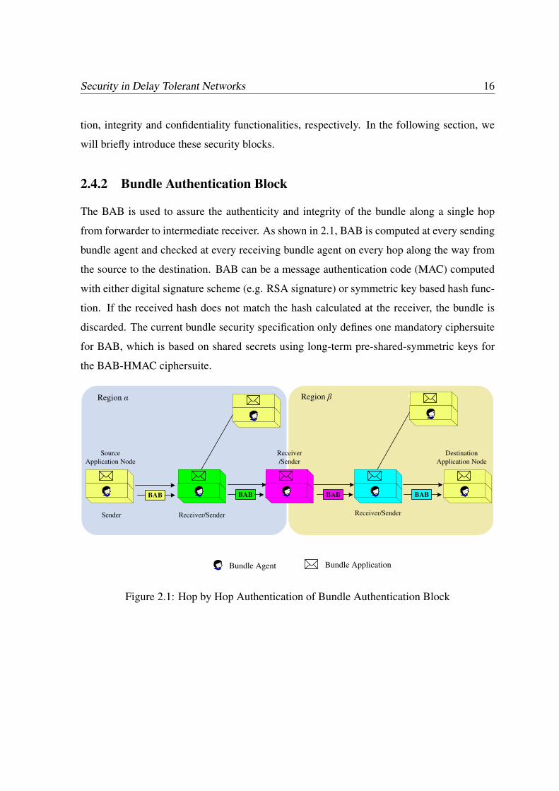
2.4.2 Bundle Authentication Block
The BAB is used to assure the authenticity and integrity of the bundle along a single hop
from forwarder to intermediate receiver. As shown in 2.1, BAB is computed at every sending
bundle agent and checked at every receiving bundle agent on every hop along the way from
the source to the destination. BAB can be a message authentication code (MAC) computed
with either digital signature scheme (e.g. RSA signature) or symmetric key based hash func-
tion. If the received hash does not match the hash calculated at the receiver, the bundle is
discarded. The current bundle security specification only defines one mandatory ciphersuite
for BAB, which is based on shared secrets using long-term pre-shared-symmetric keys for
the BAB-HMAC ciphersuite.
Bundle Agent Bundle Application
BAB BAB BAB BAB
Region Region
Source
Application Node
Sender Receiver/Sender
Receiver
/Sender
Receiver/Sender
Destination
Application Node
Figure 2.1: Hop by Hop Authentication of Bundle Authentication Block
Chapter 2. DTN Security: Threat, Requirements, Characteristics and Challenges 17
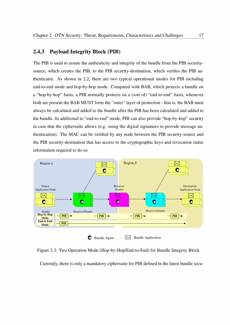
2.4.3 Payload Integrity Block (PIB)
The PIB is used to assure the authenticity and integrity of the bundle from the PIB security-
source, which creates the PIB, to the PIB security-destination, which verifies the PIB au-
thenticator. As shown in 2.2, there are two typical operational modes for PIB including
end-to-end mode and hop-by-hop mode. Compared with BAB, which protects a bundle on
a “hop-by-hop” basis, a PIB normally protects on a (sort of) “end-to-end” basis, whenever
both are present the BAB MUST form the ”outer” layer of protection - that is, the BAB must
always be calculated and added to the bundle after the PIB has been calculated and added to
the bundle. In additional to “end-to-end” mode, PIB can also provide “hop-by-hop” security
in case that the ciphersuite allows (e.g. using the digital signatures to provide message au-
thentication). The MAC can be verified by any node between the PIB security-source and
the PIB security-destination that has access to the cryptographic keys and revocation status
information required to do so.
Bundle Agent Bundle Application
Region Region
Source
Application Node
Sender Receiver/Sender
Receiver
/Sender
Receiver/Sender
Destination
Application Node
PIB
Hop by Hop
Mode
End to End
Mode
PIB PIB PIB PIB
Figure 2.2: Two Operation Mode (Hop-by-Hop/End-to-End) for Bundle Integrity Block
Currently, there is only a mandatory ciphersuite for PIB defined in the latest bundle secu-
Security in Delay Tolerant Networks 18
rity specification, which is based on digital signatures using RSA with SHA256.
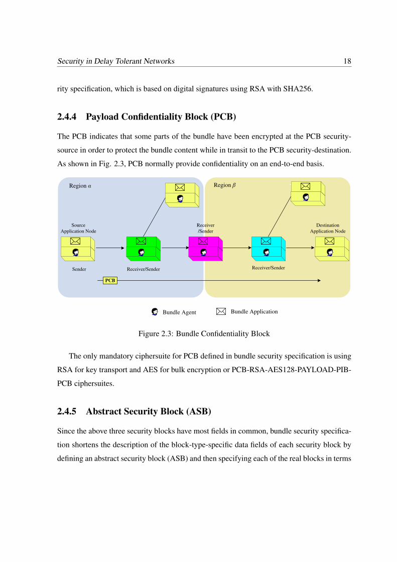
2.4.4 Payload Confidentiality Block (PCB)
The PCB indicates that some parts of the bundle have been encrypted at the PCB security-
source in order to protect the bundle content while in transit to the PCB security-destination.
As shown in Fig. 2.3, PCB normally provide confidentiality on an end-to-end basis.
Bundle Agent Bundle Application
Region Region
Source
Application Node
Sender Receiver/Sender
Receiver
/Sender
Receiver/Sender
Destination
Application Node
PCB
Figure 2.3: Bundle Confidentiality Block
The only mandatory ciphersuite for PCB defined in bundle security specification is using
RSA for key transport and AES for bulk encryption or PCB-RSA-AES128-PAYLOAD-PIB-
PCB ciphersuites.
2.4.5 Abstract Security Block (ASB)
Since the above three security blocks have most fields in common, bundle security specifica-
tion shortens the description of the block-type-specific data fields of each security block by
defining an abstract security block (ASB) and then specifying each of the real blocks in terms
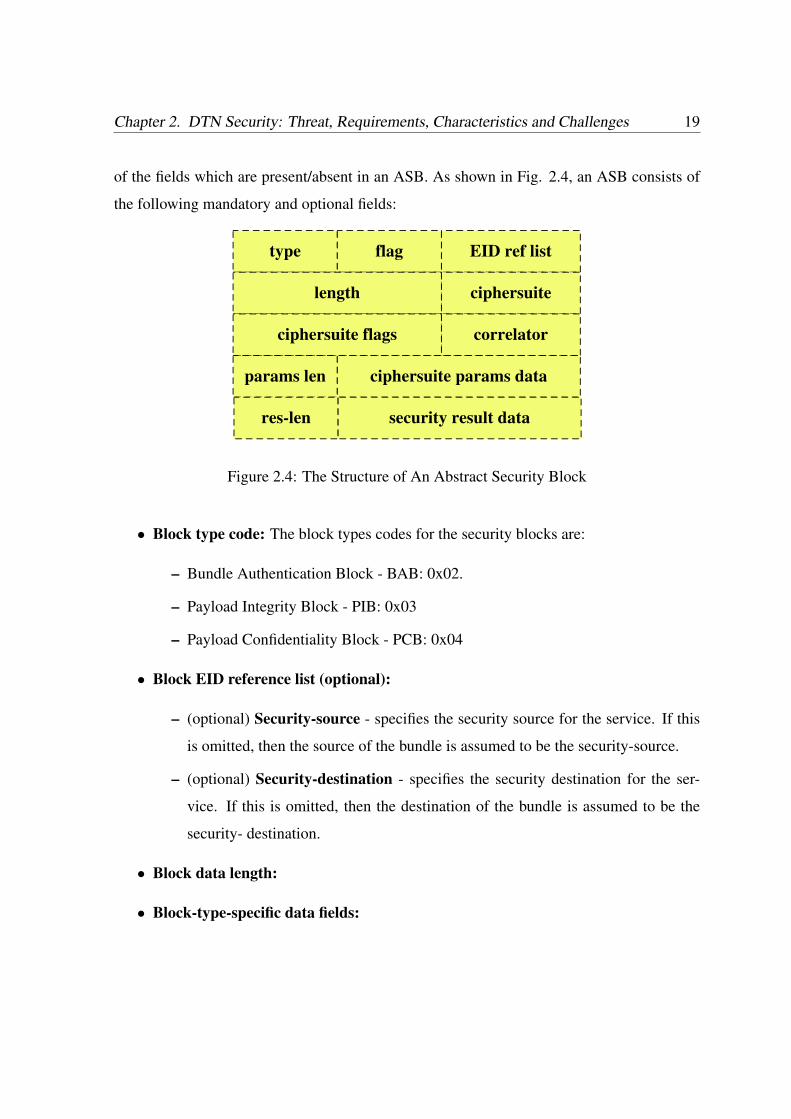
Chapter 2. DTN Security: Threat, Requirements, Characteristics and Challenges 19
of the fields which are present/absent in an ASB. As shown in Fig. 2.4, an ASB consists of
the following mandatory and optional fields:
type flag EID ref list
length ciphersuite
ciphersuite flags correlator
params len ciphersuite params data
res-len security result data
Figure 2.4: The Structure of An Abstract Security Block
• Block type code: The block types codes for the security blocks are:
– Bundle Authentication Block - BAB: 0x02.
– Payload Integrity Block - PIB: 0x03
– Payload Confidentiality Block - PCB: 0x04
• Block EID reference list (optional):
– (optional) Security-source - specifies the security source for the service. If this
is omitted, then the source of the bundle is assumed to be the security-source.
– (optional) Security-destination - specifies the security destination for the ser-
vice. If this is omitted, then the destination of the bundle is assumed to be the
security- destination.
• Block data length:
• Block-type-specific data fields:
Security in Delay Tolerant Networks 20
– Ciphersuite ID
– Ciphersuite flags
– (optional) Correlator
– (optional) Ciphersuite parameters: - includes the following two items
∗ Ciphersuite parameters length: - specifies the length of the following Ci-
phersuite parameters data field.
∗ Ciphersuite parameters data: - parameters to be used with the ciphersuite in
use.
– (optional) Security result: - includes the following two items
∗ Security result length: - contains the length of the next field.
∗ Security result data: - contains the results of the appropriate ciphersuite-
specific calculation (e.g. a signature, MAC or ciphertext block key).
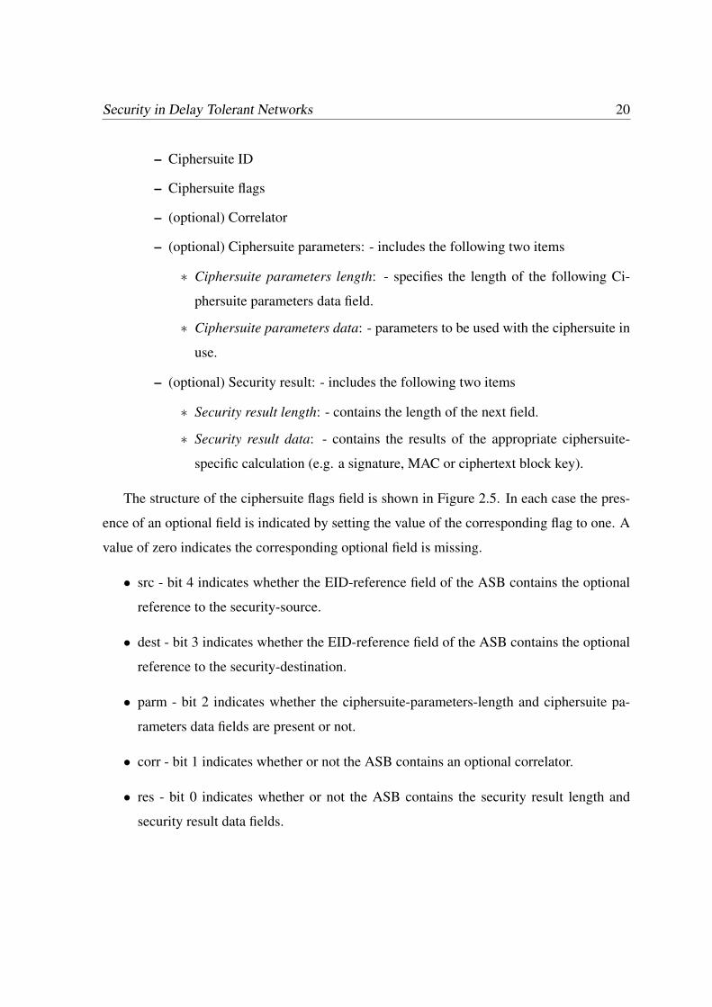
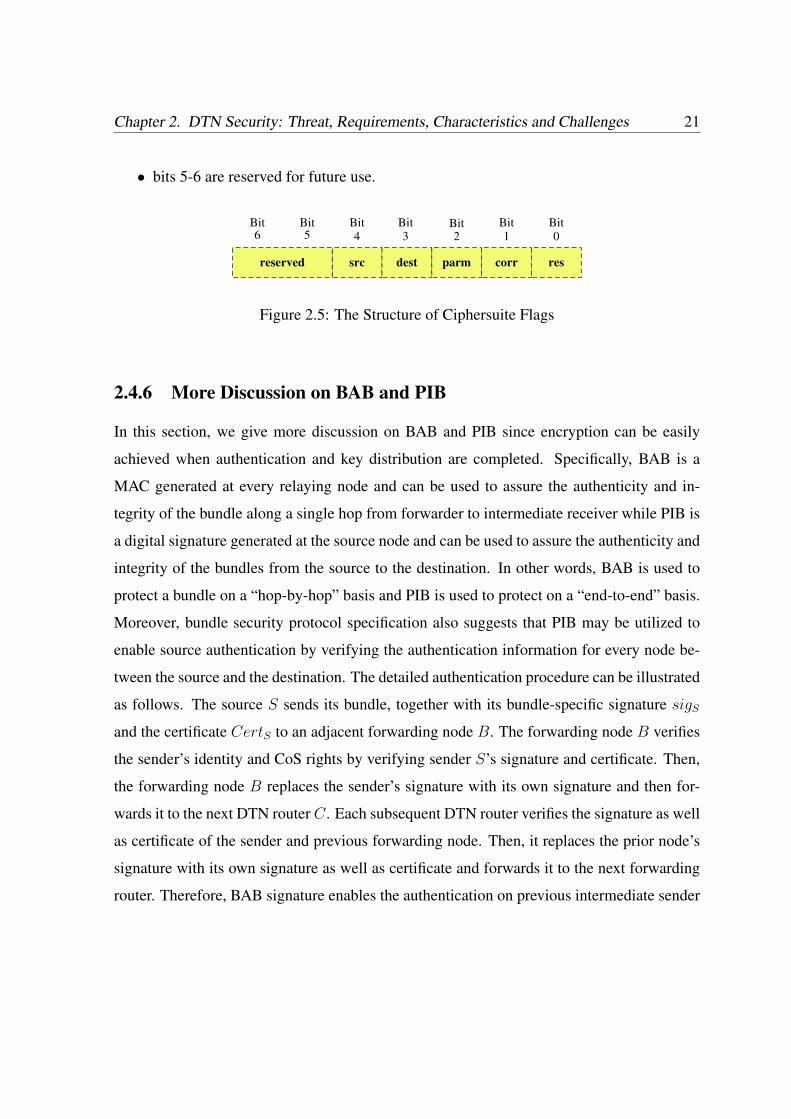
The structure of the ciphersuite flags field is shown in Figure 2.5. In each case the pres-
ence of an optional field is indicated by setting the value of the corresponding flag to one. A
value of zero indicates the corresponding optional field is missing.
• src - bit 4 indicates whether the EID-reference field of the ASB contains the optional
reference to the security-source.
• dest - bit 3 indicates whether the EID-reference field of the ASB contains the optional
reference to the security-destination.
• parm - bit 2 indicates whether the ciphersuite-parameters-length and ciphersuite pa-
rameters data fields are present or not.
• corr - bit 1 indicates whether or not the ASB contains an optional correlator.
• res - bit 0 indicates whether or not the ASB contains the security result length and
security result data fields.
Chapter 2. DTN Security: Threat, Requirements, Characteristics and Challenges 21
• bits 5-6 are reserved for future use.
src dest parm corr resreserved
Bit6
Bit5
Bit4
Bit3
Bit2
Bit1
Bit0
Figure 2.5: The Structure of Ciphersuite Flags
2.4.6 More Discussion on BAB and PIB
In this section, we give more discussion on BAB and PIB since encryption can be easily
achieved when authentication and key distribution are completed. Specifically, BAB is a
MAC generated at every relaying node and can be used to assure the authenticity and in-
tegrity of the bundle along a single hop from forwarder to intermediate receiver while PIB is
a digital signature generated at the source node and can be used to assure the authenticity and
integrity of the bundles from the source to the destination. In other words, BAB is used to
protect a bundle on a “hop-by-hop” basis and PIB is used to protect on a “end-to-end” basis.
Moreover, bundle security protocol specification also suggests that PIB may be utilized to
enable source authentication by verifying the authentication information for every node be-
tween the source and the destination. The detailed authentication procedure can be illustrated
as follows. The source S sends its bundle, together with its bundle-specific signature sigS
and the certificate CertS to an adjacent forwarding node B. The forwarding node B verifies
the sender’s identity and CoS rights by verifying sender S’s signature and certificate. Then,
the forwarding node B replaces the sender’s signature with its own signature and then for-
wards it to the next DTN router C. Each subsequent DTN router verifies the signature as well
as certificate of the sender and previous forwarding node. Then, it replaces the prior node’s
signature with its own signature as well as certificate and forwards it to the next forwarding
router. Therefore, BAB signature enables the authentication on previous intermediate sender
Security in Delay Tolerant Networks 22
while the PIB signature allows receivers as well as intermediate forwarders to confirm the
authenticity of senders, the integrity of the messages and the sender’s CoS rights.
Note that, for some ciphersuites, (e.g. those using asymmetric keying to produce sig-
natures or those using symmetric keying with a group key), the security information can be
checked at any hop on the way to the destination that has access to the required keying infor-
mation. For example, if the bundle has a PIB and the receiving node is not the bundle’s PIB
destination, the receiving node may attempt to verify the value in the security result field. If
it is able to check and the check fails, the node shall discard the bundle and it may send a
bundle status report indicating the failure.
2.5 Identified Research Challenges
Even though Bundle Security Specification has introduced a general security framework for
DTNs, it still leave several open problems, which will be introduced as follows:
2.5.1 Tradeoff between the Security and Performance
Public key signature based bundle security protocol specification supports authentication and
integrity protection of bundles, but may incur significant performance overhead, which may
prevent their real-world deployment. Firstly, the size of digital signatures and the correspond-
ing public key certificates is typically in the order of tens (using Elliptic Curve Cryptography)
to hundreds of bytes (RSA), which will introduce extra transmission and storage overheads.
Secondly and more importantly, public key signature verification typically requires compu-
tationally extensive operations, and thus verifying those individual signatures one by one at
each intermediate DTN node can significantly slow down the time each intermediate takes
to propagate the bundles. These extra communication and transmission overheads present
a great challenge to the security design in DTNs. This situation will be worse when flood-
ing or multi-copy based propagation method is employed to enhance the reliability of DTN
Chapter 2. DTN Security: Threat, Requirements, Characteristics and Challenges 23
transmission, since the signature verification operations will be performed along each data
delivery path. Therefore, how to have a tradeoff between the DTN security and efficiency
may be a critical research challenge for DTN security research.
2.5.2 Thwarting Selfish Behavior
The existing DTN routing scheme depends on the hypothesis that each individual node is
ready to forward packets for others. This assumption, however, might be easily violated due
to the existence of selfish nodes or even malicious ones, which may be unwilling to waste
their precious wireless resources by serving as bundle relays. The unique security character-
istics of DTNs may make the existing incentive scheme in traditional ad hoc networks not
workable in DTNs. Therefore, how to thwart the selfish behavior represent a second research
challenge.
2.5.3 Public Key Management/Revocation Issue
In bundle security specification, public key management is still an open problem for DTN
security. For example, public key certificate can be defined as X.509 [28] public key certifi-
cates but practical implementations may be be very strict in how they process X.509 though,
for example, it would probably not be correct to insist on Certificate Revocation List (CRL)
checking in many DTN contexts. Therefore, public key certificate management/revocation
issue still deserves further investigation
2.6 Summary
In this section, we’ve discussed the threats, requirements and characteristics related to DTN
security. We also review the bundle security specifications, which are the primary solutions
for securing DTNs. Finally, we point out three research challenges for DTN security. In the
following chapters, we will discuss these three challenges one by one.

Chapter 3
An Opportunistic Batch Bundle
Authentication Scheme for DTNs
In this chapter, we will focus on the efficiently bundle authentication issue. As we have
introduced before, although a lot of efforts have been put into the design of efficient routing
algorithms for DTNs [15, 29], there has not been much attentions on the security issues,
especially on how to ensure the authenticity and integrity of bundles during their multi-
hop transmissions. In DTNs, malicious routers can arbitrarily insert false information into
the bundles. If innocent routers further propagate these forged messages, the attackers may
generate large amount of unwanted traffic to the network, which is also known traffic storm
[30]. Due to resource-scarcity characteristic of DTNs, the extra traffic may pose a serious
threat on the operation of DTNs [31]. Further, unauthorized access and utilization of DTN
resources are another serious concern of DTN security [32].
The current primary security proposal, bundle security protocol specification [26], pro-
posed by delay tolerant networking research group (DTNRG), addresses two major DTN
security vulnerabilities, including lack of authenticity of the bundles conveyed in messages
and lack of authorization for DTN routers to appropriately access and utilize DTN resources,
both of which are related to DTN bundle authentication. Bundle security protocol specifica-
24

Chapter 3. An Opportunistic Batch Bundle Authentication Scheme for DTNs 25
tion suggests to adopt Bundle Authentication Block (BAB) or Payload Integrity Block (PIB)
to realize bundle authentication and router authorization by adding a digital signature to each
bundle. More specifically, a bundle sender can sign the bundles with its private keys and
produce a bundle-specific digital signature. This signature allows receivers as well as inter-
mediate forwarders to confirm the authenticity of the sender, the integrity of the messages
and the sender’s class-of-service (CoS) rights.
However, when public key cryptography (PKC) based bundle authentication protocol is
adopted, it has faced two main obstacles: time and space. Firstly, the size of digital signa-
tures and the corresponding public key certificates is typically very large in the order of tens
(using Elliptic Curve Cryptography) to hundreds of bytes (RSA), which will introduce extra
transmission overhead. Secondly and more importantly, public key signature verification is
typically computational extensive operations, and thus verifying those individual signatures
one by one at each intermediate DTN router can significantly slow down the time it takes for
routers to propagate the bundles. This situation worsens when flooding or multi-copy based
propagation method is employed to enhance the reliability of DTN transmission [15], since
the signature verification operations should be performed along each data delivery path. The
bundle fragmentation issue, which means an intermediate node can split a large bundle into
smaller fragments and route different fragments through different forwarding paths to make
the best use of limited resources, also increases the authentication cost since each fragment
requires an additional signature to make it self-authenticating [27].
On the other hand, the unique “store-carry-and-forward” transmission characteristic of
DTNs implies that bundles from distinct/common senders may be buffered at some common
intermediate nodes. Such a “buffering” characteristic distinguishes DTN from any other tra-
ditional wireless networks, for which intermediate cache is not supported. In our simulations,
it is observed that there exists up to 45.3% DTN contacts during which DTN transmission
is performed in a batch (three and above bundles are transferred simultaneously). To exploit
such an opportunistic buffering characteristic, in this paper, we propose an Opportunistic
Security in Delay Tolerant Networks 26
Batch Bundle Authentication Scheme (OBBA) to reduce the bundle authentication costs.
The basic OBBA scheme is an online/offline protocol, which allows the intermediate nodes
to combine the bundles during the offline phase (or carry phase) and efficiently authenticate
the combined signatures during online phase (or forwarding phase). Similar to “Opportunis-
tic Routing”, the proposed scheme can be performed opportunistically at every intermediate
node when a batch of buffered bundles need to be authenticated.
The contributions of this paper can be summarized as follows.
• Firstly, we propose a basic OBBA scheme based on identity-based (ID-based) Batch
Signature. With OBBA, the computational cost of bundle authentication is bounded by
the number of opportunistic contacts instead of the number of bundles transferred.
• Secondly, we take advantage of fragment authentication tree (FAT) to reduce the com-
munication overhead when fragmentation issue is considered. Since the communica-
tion overhead is determined by the FAT tree height, reactive fragment possibility and
fragment size, we discuss how to derive an optimal tree height based on the estimated
global network information.
• Thirdly, we propose an advanced OBBA scheme to achieve both of communication
and computation efficiency by seamlessly integrating OBBA and FAT scheme.
• Lastly, we implement the OBBA on the existing DTN routing protocols. Detailed
simulation results in terms of computational time, transmission overhead and energy
consumption, are given to demonstrate the efficiency and effectiveness of the proposed
schemes.
To the best of our knowledge, this is the first research effort towards exploiting the unique
opportunistic bundle buffering characteristic of DTNs to reduce the security cost. The re-
mainder of the paper is organized as follows. In Section 3.1, some preliminaries related to
DTN security and bundle authentication are reviewed. In Section 4.2, we present the system
Chapter 3. An Opportunistic Batch Bundle Authentication Scheme for DTNs 27
Bundle,
SigS, CertS
Source S Intermediary B Intermediary C Destination D
Bundle,
SigS, CertS,
SigB, CertB
Bundle,
SigS, CertS,
SigC, CertC
Opportunistic Link
Figure 3.1: Hop-by-Hop Bundle Authentication in DTN
model, adversary model, and the design goals. In Section 3.3, the proposed OBBA scheme
is presented in details. Simulation results and performance analysis are given in Section V,
followed by the conclusion in Section VI.
3.1 Preliminaries
3.1.1 DTN Security and Bundle Authentication
It has been widely recognized that security issue is one of the major challenges for DTN
design [32]. Due to resource-scarcity characteristic of DTNs, a general motivation for DTN
security is to prevent the attackers from unauthorized accessing and utilizing of DTN re-
sources. In the current “Bundle Security Protocol Specification” [26], there are two types of
security blocks which are related to bundle authentication: the Bundle Authentication Block
(BAB) and the Payload Integrity Block (PIB). Specifically, BAB is used to protect a bundle
on a “hop-by-hop” basis and PIB protect on a “end-to-end” basis. The detailed authentica-
tion procedure can be illustrated by Fig. 3.1. The source S sends its bundle, together with
its bundle-specific signature sigS (PIB) and the certificate CertS to an adjacent forwarding
node B. The forwarding node B verifies the sender’s identity and CoS rights by verifying
sender S’s signature and certificate. Then, the forwarding node B adds its own signature
SigB (BAB) and then forwards it to the next DTN router C. Each subsequent DTN router

Security in Delay Tolerant Networks 28
verifies the signature as well as certificate of the sender and previous forwarding node. Then,
it replaces the prior node’s signature with its own signature as well as certificate and forwards
it to the next forwarding router.
Even though Bundle Security Protocol Specification has provided a general framework
to secure DTNs, there are still two open problems, including fragment authentication issue
and performance issue.
• Fragmentation Issue: Fragmentation is a unique characteristic of DTNs. Due to lim-
ited contact duration, when a message is large, it may not be possible to send the entire
message at once. One possible solution is to split the message into smaller pieces and
let each become its own bundle, or “fragment bundle”, and send some pieces of a large
message through the current link and rest of the message through another link later
to make the best use of limited resources. Due to fragmentation, traditional authen-
tication scheme, e.g., the sender generates the signature over an entire message, may
not work well since the intermediate receiver cannot authenticate any of the received
fragments if it has not yet received the entire message. To address this problem, one
approach called “toilet paper” was proposed in [27]. The main idea is to make each
fragment self-authenticating by attaching a signature to the end of each fragment sep-
arately. However, this approach may lead to a more serious performance issue since
the intermediate nodes have to spend more computational and transmission efforts in
transmitting and verifying a growing number of signatures.
• Performance Issue: Due to the resource-scarcity characteristic of DTN, how to min-
imize the security cost and improve the bundle authentication efficiency represents a
critical problem for DTN security. The public key signature based individual bundle
authentication scheme may face the challenges of expensive computational cost and
transmission cost. Efficiency issue is extremely important in DTNs because the multi-
copy routing/forwarding is very common in DTNs and the fragmentation issue also
makes this problem more challenging.
Chapter 3. An Opportunistic Batch Bundle Authentication Scheme for DTNs 29
Since the above described two issues are closely related, we aims to address these two issues
together. The general objective of this paper is to minimize the computational and transmis-
sion overhead by exploiting the bundle buffering characteristics.
3.1.2 Identity based Cryptography
Identity based Cryptography (or IBC) is a relatively new cryptographic method and also a
powerful alternative to traditional certificate-based cryptography. Its main idea is to make
an entity’s public key directly derivable from its publicly known identity information such
as e-mail address. Eliminating the need for public-key certificates and their management
makes IBC much more appealing for securing DTNs, where the need to transmit and check
certificates has been identified as a significant limitation. Recently, there are quite a few
recommendation on adoption of IBC in DTNs, [33] [25]. OBBA will also adopt IBC as the
cryptographic foundation, which is based on bilinear pairing concept. We briefly introduce
bilinear pairing as follows: LetG be a cyclic additive group andGT be a cyclic multiplicative
group of the same order q, i.e., |G| = |GT | = q. Let P be a generator of G. We further
assume that e : G × G → GT be an efficient admissible bilinear map with the following
properties:
• Bilinear: for a, b ∈ Z∗q , e(aP, bP ) = e(P, P )ab.
• Non-degenerate: e(P, P ) 6= 1GT.
• Computable: there is an efficient algorithm to compute e(P1, Q1) for any P1, Q1 ∈ G.
According to [34], such an admissible bilinear map e can be constructed by Weil or Tate
pairings on the elliptic curves.
3.2 Models and Design Goals
This section describes our system model and adversary model, followed by design goals.
Security in Delay Tolerant Networks 30
3.2.1 System Model
Consider a DTN as a directed graph G = (V, E), where V and E represent the set of nodes
and edges, respectively. A source node can deliver packets to a destination node via one or
multiple pathes depending on any particular forwarding algorithm such as [15]. Specifically,
for a given intermediate node F , it may contemporarily receive bundles Mij|1 ≤ j ≤ kifrom multiple bundle senders IDi|1 ≤ i ≤ n via one or multiple hops. The received
packets Mij|1 ≤ i ≤ n, 1 ≤ j ≤ ki will be buffered until the next link in the path
appears. At the system initialization phase, we follow a general assumption such as [25] that
an Offline Security Manager (OSM) exists to take charge of key distribution and periodical
revocation. Before joining the network, each DTN node should register to the OSM and
obtain its corresponding ID-based secret key.
3.2.2 Adversary Model
Assume that the adversary’s goal is to inject bogus messages into the network, attempt to
deceive other DTN nodes, and gain unauthorized access to DTN resources. Additionally,
Denial of Service (DoS) attack such as bogus message flooding, aiming at exhausting con-
strained network resources, is another important focus of the paper. However, we do not
consider that the adversary is able to compromise DTN nodes.
3.2.3 Design Goals
Our security goal is straightforward: all messages relayed should be authenticated so that
the bogus ones inserted by the illegitimate DTN users or external attackers can be efficiently
rejected/filtered as early as possible. We also focus on minimizing the overheads of the
security design. Especially, computational cost, communication overhead as well as energy
efficiency (with respect to both communication and computation) are given priority to cope
with the resource-constrained nature of DTNs.
Chapter 3. An Opportunistic Batch Bundle Authentication Scheme for DTNs 31
3.3 The Proposed Scheme
In this section, firstly, we propose a basic OBBA scheme which aims to minimize the compu-
tational overhead by exploiting the bundle buffering opportunities. Then, we take advantage
of fragment authentication tree technique (FAT) technique to further reduce the communi-
cation overhead. Lastly, we propose an advanced OBBA scheme by integrating OBBA and
FAT.
3.3.1 The Basic OBBA
The main computational cost for authenticating the bundles comes from verifying a set of
bundle-specific signatures issued by different bundle senders. The corresponding public key
certificates of the signers also need to be verified together. All of them will incur a signifi-
cant amount of verification cost. On the other hand, the unique “Store-Carry-and-Forward”
transmission strategy of DTN implies that the bundles can be verified in batch instead of one
by one.
ID-based Batch Signature
Recently, batch signature techniques have emerged to permit the signature verifier to quickly
verify a set of digital signatures on different messages. A batch signature is a digital signa-
ture that supports batch verification: given n signatures on n distinct messages by n distinct
users, using a batch signature algorithm, it is possible for a batch verifier to combine these
multiple signatures into a single signature and then verify it. This single signature will con-
vince the verifier that the n users indeed sign the n original messages. There are quite a few
batch signature techniques available, of which we refer [35] for a comprehensive survey. The
choice in this work is the ID-based batch signature [36], the benefits of which are twofold:
1) it inherits the advantage of IBC that eliminates the need for a public key distribution in-
frastructure and relieves the verifier from checking the authenticity of public key certificates;

Security in Delay Tolerant Networks 32
2) the batch verification technique enables the verifiers to quickly verify a set of digital sig-
natures on different messages by different signers. We briefly summarize the ID-based batch
signature scheme in [36] as follows.
1. System Parameter: Choose a random number s ∈ Z∗q as the system private key and
compute Ppub = sP as the system public key. Let H1 : 0, 1∗ × G → Z∗q and
H2 : 0, 1∗ → G be two hash functions.
2. Sign: For a particular DTN node ωi, given the private key ski = sH2(ωi) corresponding
to the public key ωi and a bundle Bj , choose a random number r; compute Uij ←rH2(ωi), hj ← H1(Bj, Uij) and Vij ← (r + hj)ski. σij = (Uij, Vij) is the signature.
3. IndividualVerify: Given the node identity ωi, bundle Bj and the signature σij , com-
pute hj ← H1(Bj, Uij) and accept it as a valid signature if e(P, Vij) = e(Ppub, Uij +
hjH2(ωi)).
4. SigCombine: Given a set of nodes ωi|1 ≤ i ≤ k, each of which generates signatures
σji |1 ≤ j ≤ ni on bundles Bj
i |1 ≤ j ≤ ni, compute VBatch =∑k
i=1
∑ni
j=1 Vij ,
UBatch =∑k
i=1
∑ni
j=1 Uij + hjpki. σ′ = (VBatch, UBatch) is the combined signature.
5. SigBatchVerify: Given the combined signature VBatch and UBatch, the bundle set Bji |1 ≤
i ≤ k, 1 ≤ j ≤ ni on which it is based for all senders ωi|1 ≤ i ≤ k, the verifier
can authenticate the bundles by checking if e(P, VBatch) = e(Ppub, UBatch) holds.
Note that the signature combination can be performed incrementally. The computation costs
are measured by the most expensive point pairing operations. It is obvious that, given n unau-
thenticated signatures, in the SigCombine phase, n less expensive multiplication operation is
required while, in the SigBatchVerify phase, the computational cost is bounded by 2 pairings,
which is a significant improvement over the 2n pairings required by individual verification.
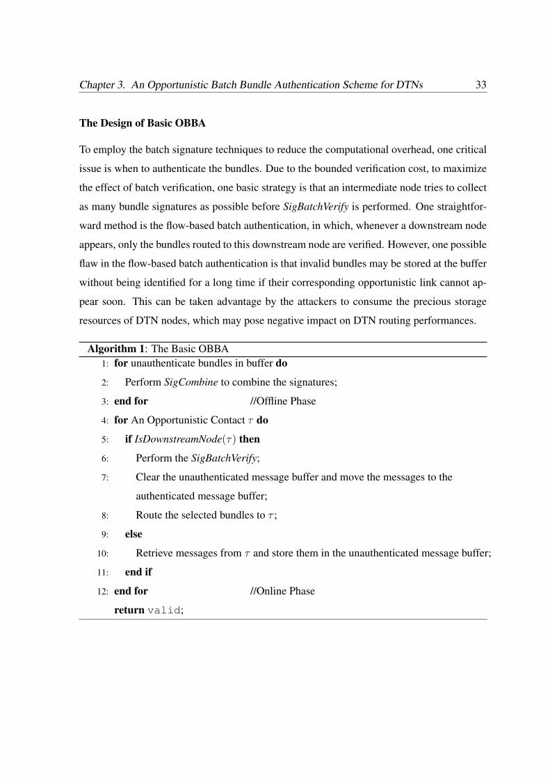
Chapter 3. An Opportunistic Batch Bundle Authentication Scheme for DTNs 33
The Design of Basic OBBA
To employ the batch signature techniques to reduce the computational overhead, one critical
issue is when to authenticate the bundles. Due to the bounded verification cost, to maximize
the effect of batch verification, one basic strategy is that an intermediate node tries to collect
as many bundle signatures as possible before SigBatchVerify is performed. One straightfor-
ward method is the flow-based batch authentication, in which, whenever a downstream node
appears, only the bundles routed to this downstream node are verified. However, one possible
flaw in the flow-based batch authentication is that invalid bundles may be stored at the buffer
without being identified for a long time if their corresponding opportunistic link cannot ap-
pear soon. This can be taken advantage by the attackers to consume the precious storage
resources of DTN nodes, which may pose negative impact on DTN routing performances.
Algorithm 1: The Basic OBBA1: for unauthenticate bundles in buffer do
2: Perform SigCombine to combine the signatures;
3: end for //Offline Phase
4: for An Opportunistic Contact τ do
5: if IsDownstreamNode(τ) then
6: Perform the SigBatchVerify;
7: Clear the unauthenticated message buffer and move the messages to the
authenticated message buffer;
8: Route the selected bundles to τ ;
9: else
10: Retrieve messages from τ and store them in the unauthenticated message buffer;
11: end if
12: end for //Online Phase
return valid;
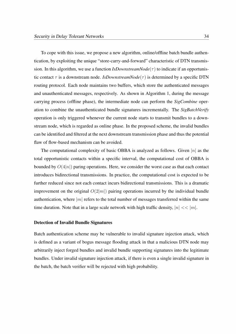
Security in Delay Tolerant Networks 34
To cope with this issue, we propose a new algorithm, online/offline batch bundle authen-
tication, by exploiting the unique “store-carry-and-forward” characteristic of DTN transmis-
sion. In this algorithm, we use a function IsDownstreamNode(τ) to indicate if an opportunis-
tic contact τ is a downstream node. IsDownstreamNode(τ) is determined by a specific DTN
routing protocol. Each node maintains two buffers, which store the authenticated messages
and unauthenticated messages, respectively. As shown in Algorithm 1, during the message
carrying process (offline phase), the intermediate node can perform the SigCombine oper-
ation to combine the unauthenticated bundle signatures incrementally. The SigBatchVerify
operation is only triggered whenever the current node starts to transmit bundles to a down-
stream node, which is regarded as online phase. In the proposed scheme, the invalid bundles
can be identified and filtered at the next downstream transmission phase and thus the potential
flaw of flow-based mechanism can be avoided.
The computational complexity of basic OBBA is analyzed as follows. Given |n| as the
total opportunistic contacts within a specific interval, the computational cost of OBBA is
bounded by O(4|n|) paring operations. Here, we consider the worst case as that each contact
introduces bidirectional transmissions. In practice, the computational cost is expected to be
further reduced since not each contact incurs bidirectional transmissions. This is a dramatic
improvement on the original O(2|m|) pairing operations incurred by the individual bundle
authentication, where |m| refers to the total number of messages transferred within the same
time duration. Note that in a large scale network with high traffic density, |n| << |m|.
Detection of Invalid Bundle Signatures
Batch authentication scheme may be vulnerable to invalid signature injection attack, which
is defined as a variant of bogus message flooding attack in that a malicious DTN node may
arbitrarily inject forged bundles and invalid bundle supporting signatures into the legitimate
bundles. Under invalid signature injection attack, if there is even a single invalid signature in
the batch, the batch verifier will be rejected with high probability.
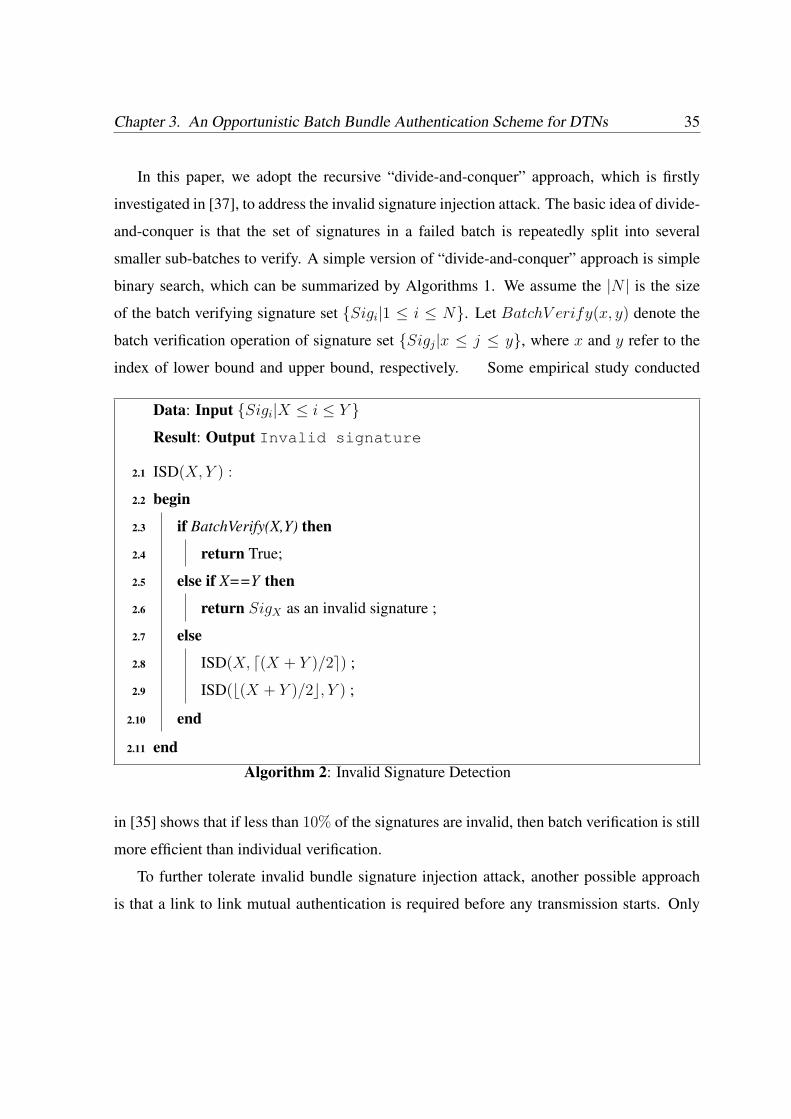
Chapter 3. An Opportunistic Batch Bundle Authentication Scheme for DTNs 35
In this paper, we adopt the recursive “divide-and-conquer” approach, which is firstly
investigated in [37], to address the invalid signature injection attack. The basic idea of divide-
and-conquer is that the set of signatures in a failed batch is repeatedly split into several
smaller sub-batches to verify. A simple version of “divide-and-conquer” approach is simple
binary search, which can be summarized by Algorithms 1. We assume the |N | is the size
of the batch verifying signature set Sigi|1 ≤ i ≤ N. Let BatchV erify(x, y) denote the
batch verification operation of signature set Sigj|x ≤ j ≤ y, where x and y refer to the
index of lower bound and upper bound, respectively. Some empirical study conducted
Data: Input Sigi|X ≤ i ≤ Y Result: Output Invalid signature
ISD(X,Y ) :2.1
begin2.2
if BatchVerify(X,Y) then2.3
return True;2.4
else if X==Y then2.5
return SigX as an invalid signature ;2.6
else2.7
ISD(X, d(X + Y )/2e) ;2.8
ISD(b(X + Y )/2c, Y ) ;2.9
end2.10
end2.11
Algorithm 2: Invalid Signature Detection
in [35] shows that if less than 10% of the signatures are invalid, then batch verification is still
more efficient than individual verification.
To further tolerate invalid bundle signature injection attack, another possible approach
is that a link to link mutual authentication is required before any transmission starts. Only
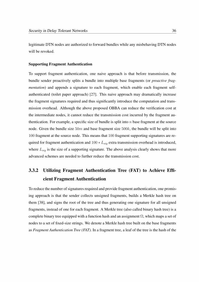
Security in Delay Tolerant Networks 36
legitimate DTN nodes are authorized to forward bundles while any misbehaving DTN nodes
will be revoked.
Supporting Fragment Authentication
To support fragment authentication, one naive approach is that before transmission, the
bundle sender proactively splits a bundle into multiple base fragments (or proactive frag-
mentation) and appends a signature to each fragment, which enable each fragment self-
authenticated (toilet paper approach) [27]. This naive approach may dramatically increase
the fragment signatures required and thus significantly introduce the computation and trans-
mission overhead. Although the above proposed OBBA can reduce the verification cost at
the intermediate nodes, it cannot reduce the transmission cost incurred by the fragment au-
thentication. For example, a specific size of bundle is split into n base fragment at the source
node. Given the bundle size 50m and base fragment size 500k, the bundle will be split into
100 fragment at the source node. This means that 100 fragment supporting signatures are re-
quired for fragment authentication and 100 ∗ Lsig extra transmission overhead is introduced,
where Lsig is the size of a supporting signature. The above analysis clearly shows that more
advanced schemes are needed to further reduce the transmission cost.
3.3.2 Utilizing Fragment Authentication Tree (FAT) to Achieve Effi-
cient Fragment Authentication
To reduce the number of signatures required and provide fragment authentication, one promis-
ing approach is that the sender collects unsigned fragments, builds a Merkle hash tree on
them [38], and signs the root of the tree and thus generating one signature for all unsigned
fragments, instead of one for each fragment. A Merkle tree (also called binary hash tree) is a
complete binary tree equipped with a function hash and an assignment Ω, which maps a set of
nodes to a set of fixed-size strings. We denote a Merkle hash tree built on the base fragments
as Fragment Authentication Tree (FAT). In a fragment tree, a leaf of the tree is the hash of the
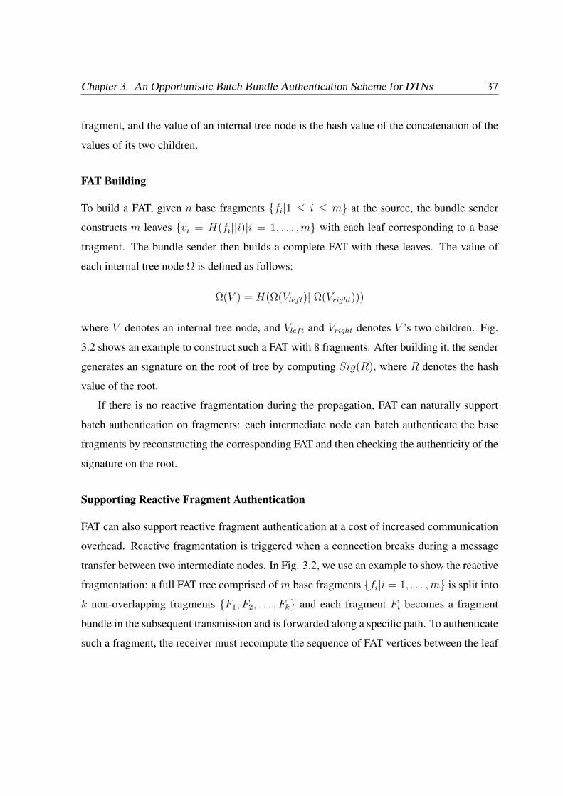
Chapter 3. An Opportunistic Batch Bundle Authentication Scheme for DTNs 37
fragment, and the value of an internal tree node is the hash value of the concatenation of the
values of its two children.
FAT Building
To build a FAT, given n base fragments fi|1 ≤ i ≤ m at the source, the bundle sender
constructs m leaves vi = H(fi||i)|i = 1, . . . , m with each leaf corresponding to a base
fragment. The bundle sender then builds a complete FAT with these leaves. The value of
each internal tree node Ω is defined as follows:
Ω(V ) = H(Ω(Vleft)||Ω(Vright)))
where V denotes an internal tree node, and Vleft and Vright denotes V ’s two children. Fig.
3.2 shows an example to construct such a FAT with 8 fragments. After building it, the sender
generates an signature on the root of tree by computing Sig(R), where R denotes the hash
value of the root.
If there is no reactive fragmentation during the propagation, FAT can naturally support
batch authentication on fragments: each intermediate node can batch authenticate the base
fragments by reconstructing the corresponding FAT and then checking the authenticity of the
signature on the root.
Supporting Reactive Fragment Authentication
FAT can also support reactive fragment authentication at a cost of increased communication
overhead. Reactive fragmentation is triggered when a connection breaks during a message
transfer between two intermediate nodes. In Fig. 3.2, we use an example to show the reactive
fragmentation: a full FAT tree comprised of m base fragments fi|i = 1, . . . , m is split into
k non-overlapping fragments F1, F2, . . . , Fk and each fragment Fi becomes a fragment
bundle in the subsequent transmission and is forwarded along a specific path. To authenticate
such a fragment, the receiver must recompute the sequence of FAT vertices between the leaf
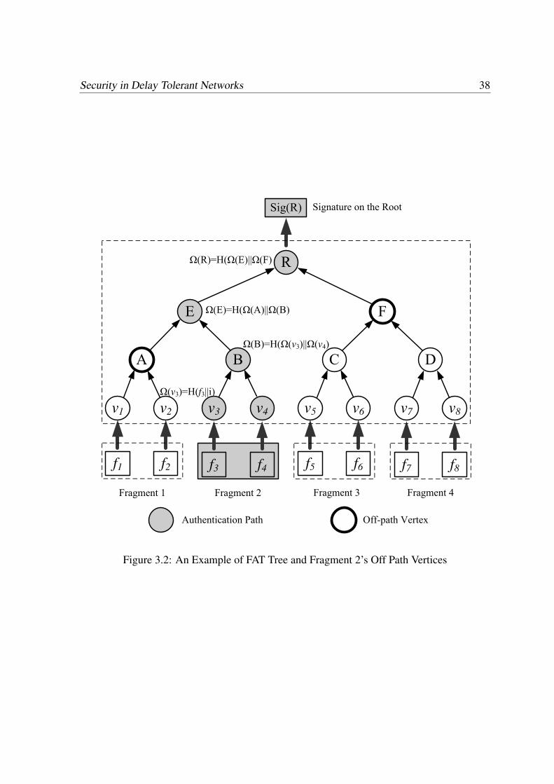
Security in Delay Tolerant Networks 38
E F
R
Authentication Path
DCBA
v1 v2 v3 v4 v6 v7 v8v5
f1 f2 f3 f4 f5 f6 f7 f8
Signature on the RootSig(R)
Off-path Vertex
Fragment 2Fragment 1 Fragment 3 Fragment 4
(B)=H( (v3)|| (v4)
(E)=H( (A)|| (B)
(R)=H( (E)|| (F)
(v3)=H(f3||i)
Figure 3.2: An Example of FAT Tree and Fragment 2’s Off Path Vertices
Chapter 3. An Opportunistic Batch Bundle Authentication Scheme for DTNs 39
vertices and the root. For example, in Fig. 3.2, the receiver of fragment F2 needs to compute
the vertices v3, v4, B, E, and R. To perform this series of computations, each node must
receive all the off-path vertices of its leaf vertex. The off-path vertices of a leaf vertex fi are
the sibling vertices of all nodes on the path from fi to the root of the tree [39]. In Fig. 3.2,
this means that the verifier must receive all the child vertices of B, E, and R respectively;
this corresponds to the set A,F.
The transmission of off-path vertices will increase the transmission overhead of the FAT
scheme. Specifically, the following theorem shows that the transmission overhead will be
determined by the FAT tree height reactive fragment probability and fragment size.
Theorem 1: Given a FAT tree with height h, which corresponds to 2h−1 leave vertices,
and reactive fragmentation size s (for simplicity, we assume s ≤ 2h−2), the transmission cost
incurred by authenticating total N fragments sent by a sender is
T1 = ((h− 1− blog2sc)Lhash + LSig)d2h−1
sed N
2h−1e, (3.1)
where Lhash and Lsig refer to the length of a hash value and a signature, respectively.
Proof: When s = 1, the number of nodes along the authentication path equals the height
h − 1, which means the number of off-path vertices equal h − 1. For subsequent s =
2, . . . , 2i, . . . , 2h−2, the number of off-path vertices will decrease one whenever the height
of subtree formed by the fragment size increases one. Therefore, we can obtain the number
of off-path vertices as h − 1 − blog2sc, which contributes to the transmission overhead as
(h− 1−blog2sc)Lhash. So, the transmission cost for a fragment is (h− 1−blog2sc)Lhash +
LSig. Since there are d N2h−1 e FATs and each FAT is split into d2h−1
se fragments, the total
transmission cost is ((h− 1− blog2sc)Lhash + LSig)d2h−1
sed N
2h−1 e. ¥From Theorem 1, it is obvious that, given the fixed fragmentation probability, fragment
size, the transmission cost will grow with the tree height. On the other hand, if there is no
reactive fragment, the sender only needs to send a root signature to verify the whole hash
tree. Therefore, the transmission cost without fragmentation is
T2 = LSig ∗ d N
2h−1e, (3.2)
Security in Delay Tolerant Networks 40
In this case, the transmission overhead will decrease when tree height h grows. Therefore,
there exists an optimal tree height to minimize the average transmission overhead, which will
be discussed in the following section.
Finding the Optimal FAT Tree Height to Minimize Transmission Overhead
We estimate the average transmission cost for fragment authentication under a simplified
fragmentation model. Let each message traverse K hops before arriving the destination and
the message have the chance of p to be fragmented at any intermediate node for the fragment
size s but will not be further fragmented after the first fragmentation1. Therefore, we can
obtain the average transmission cost for a message of size N as follows:
T =K−1∑
k=0
((K − k)T1 + kT2)(1− p)kp + KT2 ∗ (1− p)K (3.3)
= (K − A) ∗ T1 + A ∗ T2 (3.4)
where A = 1−pp∗ (1− (1− p)K).
The following theorem gives the optimal FAT tree height h to achieve a minimal trans-
mission overhead.
Theorem 2: Given the reactive fragment size s, the fragmentation probability p and the
average hop number K, the optimal FAT tree height h for achieving the minimal transmission
overhead is
h = 1 + log2sAIn2LSig
(K − A)Lhash
(3.5)
where A = 1−pp∗ (1− (1− p)K).
Proof: Since T = (K −A) ∗ T1 + A ∗ T2, to minimize the transmission overhead T , we
havedT
dh= (K − A)Lhashd2
h−1
sed N
2h−1e − In2NALSig
2h−1
1A recent study shows that the fragment size may follow a certain distribution in practice [44]. A more
advanced fragmentation model deserves further investigation. In this study, for the simplicity of presentation,
we adopt a simplified fragmentation model to introduce our approach.
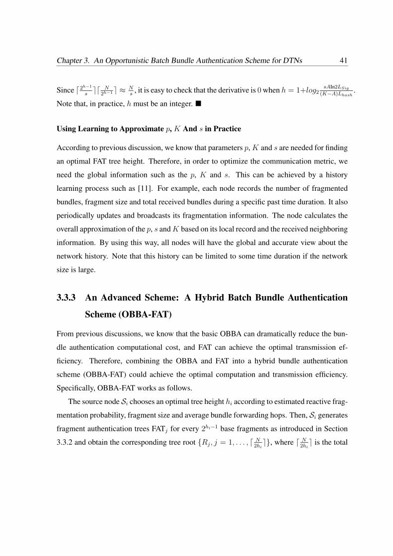
Chapter 3. An Opportunistic Batch Bundle Authentication Scheme for DTNs 41
Since d2h−1
sed N
2h−1 e ≈ Ns
, it is easy to check that the derivative is 0 when h = 1+log2sAIn2LSig
(K−A)Lhash.
Note that, in practice, h must be an integer. ¥
Using Learning to Approximate p, K And s in Practice
According to previous discussion, we know that parameters p, K and s are needed for finding
an optimal FAT tree height. Therefore, in order to optimize the communication metric, we
need the global information such as the p, K and s. This can be achieved by a history
learning process such as [11]. For example, each node records the number of fragmented
bundles, fragment size and total received bundles during a specific past time duration. It also
periodically updates and broadcasts its fragmentation information. The node calculates the
overall approximation of the p, s and K based on its local record and the received neighboring
information. By using this way, all nodes will have the global and accurate view about the
network history. Note that this history can be limited to some time duration if the network
size is large.
3.3.3 An Advanced Scheme: A Hybrid Batch Bundle Authentication
Scheme (OBBA-FAT)
From previous discussions, we know that the basic OBBA can dramatically reduce the bun-
dle authentication computational cost, and FAT can achieve the optimal transmission ef-
ficiency. Therefore, combining the OBBA and FAT into a hybrid bundle authentication
scheme (OBBA-FAT) could achieve the optimal computation and transmission efficiency.
Specifically, OBBA-FAT works as follows.
The source node Si chooses an optimal tree height hi according to estimated reactive frag-
mentation probability, fragment size and average bundle forwarding hops. Then, Si generates
fragment authentication trees FATj for every 2hi−1 base fragments as introduced in Section
3.3.2 and obtain the corresponding tree root Rj, j = 1, . . . , d N2hie, where d N
2hie is the total

Security in Delay Tolerant Networks 42
FAT number. Finally, Si generates an ID-based batch signature for each root as defined in
Section 3.3.1 and obtains the signatures σj = Sign(Rj), where j = 1, . . . , d N2hie. Here,
Rj, σj, j = 1, . . . , d N2hie constitutes the authentication blocks for fragment authentication.
The intermediate node N receives fragments and authentication blocks Rj, σj, j =
1, . . . , M from multiple senders, where M denotes the total number of FATs. Upon re-
ceiving them, node N reconstructs the FAT trees and obtains the root values. Note that, if
a fragment of the bundle is received, node N needs the offline vertices to rebuild the FAT
trees. If the constructed FAT roots R′j equals to the received FAT root Rj , N performs
SigCombine to combine the signatures σj, j = 1, . . . , M. The above described operations
are performed during the offline phase. In the online phase when an opportunistic contact
appears, N performs the SigBatchVerify operation to batch authenticate the bundles. The
above described advanced batch bundle authentication is illustrated in Fig. 3.3.
3.4 Simulations and Performance Evaluation
We implement the OBBA scheme on a public available DTN simulator Opportunistic Net-
working Environment (ONE) simulator [40] and evaluate its performance. We run simulation
with 200 mobile nodes uniformly deployed in an area of 4000 by 4000 meters. The average
speed of each node varies from 1 km/h ∼ 1.5km/h and the transmission coverage of each
node is 300 m. The map adopted in the study is extracted from a real city map, which makes
the model realistic. Each mobile node is first randomly scattered on one position of the roads
and move towards another randomly selected position along the paths in the map. The details
of our simulation parameters are summarized in Table 3.1.
Based on above parameter setting, we implement the OBBA on top of a typical multi-
copy DTN routing protocol, Spray and Wait routing (SW) protocol [15]. However, it is
important to point out that OBBA scheme can be also applied to other routing schemes to
realize efficient secure DTN routing. To demonstrate the superiority of OBBA, we compare
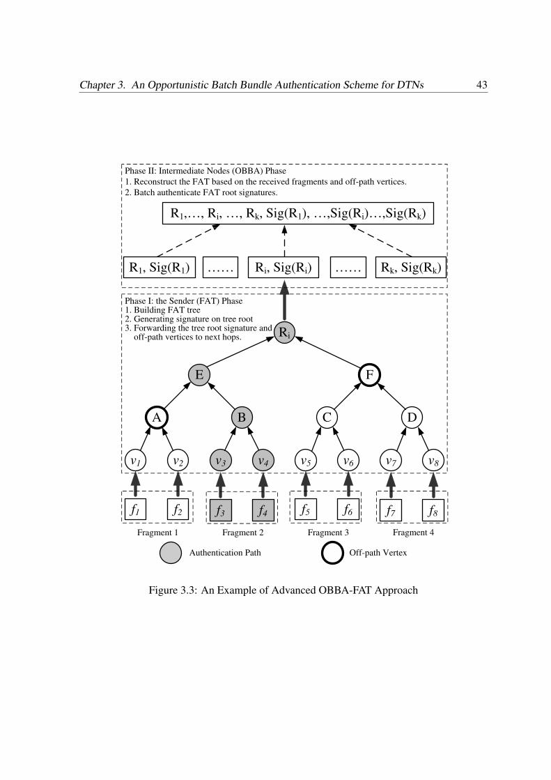
Chapter 3. An Opportunistic Batch Bundle Authentication Scheme for DTNs 43
E F
Ri
DCBA
v1 v2 v3 v4 v6 v7 v8v5
f1 f2 f3 f4 f5 f6 f7 f8
Ri, Sig(Ri)
Phase I: the Sender (FAT) Phase 1. Building FAT tree2. Generating signature on tree root3. Forwarding the tree root signature and off-path vertices to next hops.
R1, Sig(R1) …… Rk, Sig(Rk)……
R1,…, Ri, …, Rk, Sig(R1), …,Sig(Ri)…,Sig(Rk)
Phase II: Intermediate Nodes (OBBA) Phase
1. Reconstruct the FAT based on the received fragments and off-path vertices.
2. Batch authenticate FAT root signatures.
Fragment 1 Fragment 2 Fragment 3 Fragment 4
Authentication Path Off-path Vertex
Figure 3.3: An Example of Advanced OBBA-FAT Approach
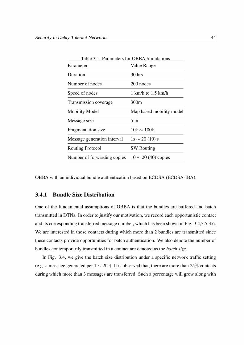
Security in Delay Tolerant Networks 44
Table 3.1: Parameters for OBBA SimulationsParameter Value Range
Duration 30 hrs
Number of nodes 200 nodes
Speed of nodes 1 km/h to 1.5 km/h
Transmission coverage 300m
Mobility Model Map based mobility model
Message size 5 m
Fragmentation size 10k ∼ 100k
Message generation interval 1s ∼ 20 (10) s
Routing Protocol SW Routing
Number of forwarding copies 10 ∼ 20 (40) copies
OBBA with an individual bundle authentication based on ECDSA (ECDSA-IBA).
3.4.1 Bundle Size Distribution
One of the fundamental assumptions of OBBA is that the bundles are buffered and batch
transmitted in DTNs. In order to justify our motivation, we record each opportunistic contact
and its corresponding transferred message number, which has been shown in Fig. 3.4,3.5,3.6.
We are interested in those contacts during which more than 2 bundles are transmitted since
these contacts provide opportunities for batch authentication. We also denote the number of
bundles contemporarily transmitted in a contact are denoted as the batch size.
In Fig. 3.4, we give the batch size distribution under a specific network traffic setting
(e.g. a message generated per 1∼ 20s). It is observed that, there are more than 25% contacts
during which more than 3 messages are transferred. Such a percentage will grow along with
Chapter 3. An Opportunistic Batch Bundle Authentication Scheme for DTNs 45
1−2 3−5 5−10 10−15 15−20 20+0
10
20
30
40
50
60
70
80
Number of bundles transferred for each contact (batch size)
Per
cent
age
of th
e ov
eral
l con
tact
s (%
)
1st hour15−th hour30−th hour
Figure 3.4: Batch Size Distribution in Normal Traffic
simulation time. For example, in the 15th and 30th hour, the percentage of batch size > 3
grows to 37.3% and 41.7%, respectively. On the contrary, the non-batch-transferred contact
will be reduced from 74.7% to 62.7% and 58.3%. This is because the number of buffered
messages will increase with times, which increases the possibility of batch transmission.
In Figs. 3.5 and 3.6, we investigate two other factors which may have impact on the batch
size distribution: the network traffic and the forwarding copies of DTN routing. In Fig. 3.5,
we increase the network traffic by changing the traffic generating interval from 1 ∼ 20s to 1
∼ 10s. We find that the possibility of batch transmission is increased from 41.7% to 45.3% at
the 30th hour. Similarly, when we change the forwarding copies from 10 copies to 20 copies,
the batch transmission possibility is also increased.
Next, we focus on the impact of fragmentation on the batch size distribution. Intuitively,
as long as the sender proactively splits the bundle into multiple fragment bundles, the in-
creased number of bundles will lead to a higher batch transmission possibility. Therefore,
the above discussions justify our motivation for batch authentication. In the following sec-
tion, we will study the effect of batch authentication on the overall authentication perfor-
mance in terms of three metrics: computational latency, transmission overhead and energy
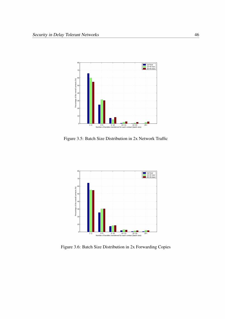
Security in Delay Tolerant Networks 46
1−2 3−5 5−10 10−15 15−20 20+0
10
20
30
40
50
60
70
80
Number of bundles transferred for each contact (batch size)
Per
cent
age
of th
e ov
eral
l con
tact
s (%
)
1st hour15−th hour30−th hour
Figure 3.5: Batch Size Distribution in 2x Network Traffic
1−2 3−5 5−10 10−15 15−20 20+0
10
20
30
40
50
60
70
80
Number of bundles transferred for each contact (batch size)
Per
cent
age
of th
e ov
eral
l con
tact
s (%
)
1st hour15−th hour30−th hour
Figure 3.6: Batch Size Distribution in 2x Forwarding Copies

Chapter 3. An Opportunistic Batch Bundle Authentication Scheme for DTNs 47
Table 3.2: ECDSA and Pairing Computation Time
Descriptions Execution Time
TECDSA: The time for a ECDSA verification 3.44 ms
TPair: The time for a pairing operation 4.14 ms
consumption.
3.4.2 Computational Cost
In this section, we analyze the computation cost of the OBBA to further justify the suitability
of the proposed scheme. The major computational cost is due to the most expensive public
key cryptographic operations such as pairing operations PPair. In the following analysis, we
omit the cost of other operations such as hash operations and multiplication operation, as
they are negligible as compared to pairing operations.
As we point out, given the batch size n which corresponds to n bundle supporting signa-
tures, only two pairing operations are needed to complete each bundle batch authentication.
We evaluate the delay of cryptographic operations on an Intel Pentium 4 3.0 GHz machine
with 1 GB RAM running Fedora Core 4 based on cryptographic library MIRACL [41], which
is shown in Table 3.2. It is observed that ECDSA signature based individual bundle authen-
tication scheme incurs 3.44n computational latency for n bundles. In comparison, the com-
putational latency incurred by OBBA is 8.28 ms, which is a dramatic improvement on the
individual authentication scheme.
We further evaluate OBBA computational cost by implementing it on DTN routing. To
support reactive fragment authentication, we assume that each source creates 1 to 100 frag-
ments instead of one message. We compare the computational efficiency of OBBA with the
ECDSA-IBA by recording the computational cost of both schemes for each interval (e.g.
15 minutes) which are shown in the Fig. 3.7. It is observed that the computational cost of
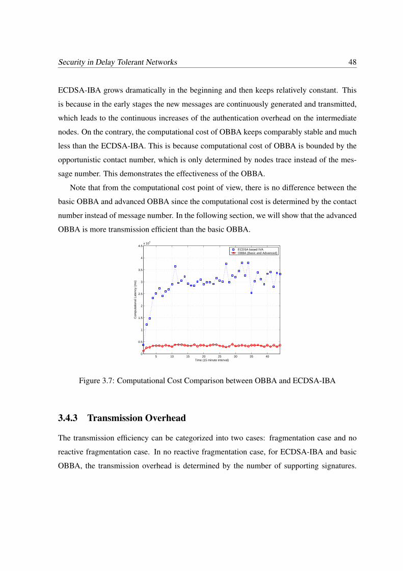
Security in Delay Tolerant Networks 48
ECDSA-IBA grows dramatically in the beginning and then keeps relatively constant. This
is because in the early stages the new messages are continuously generated and transmitted,
which leads to the continuous increases of the authentication overhead on the intermediate
nodes. On the contrary, the computational cost of OBBA keeps comparably stable and much
less than the ECDSA-IBA. This is because computational cost of OBBA is bounded by the
opportunistic contact number, which is only determined by nodes trace instead of the mes-
sage number. This demonstrates the effectiveness of the OBBA.
Note that from the computational cost point of view, there is no difference between the
basic OBBA and advanced OBBA since the computational cost is determined by the contact
number instead of message number. In the following section, we will show that the advanced
OBBA is more transmission efficient than the basic OBBA.
5 10 15 20 25 30 35 400
0.5
1
1.5
2
2.5
3
3.5
4
4.5x 10
4
Time (15 minute interval)
Com
puta
tiona
l Lat
ency
(m
s)
ECDSA based IVAOBBA (Basic and Advanced)
Figure 3.7: Computational Cost Comparison between OBBA and ECDSA-IBA
3.4.3 Transmission Overhead
The transmission efficiency can be categorized into two cases: fragmentation case and no
reactive fragmentation case. In no reactive fragmentation case, for ECDSA-IBA and basic
OBBA, the transmission overhead is determined by the number of supporting signatures.
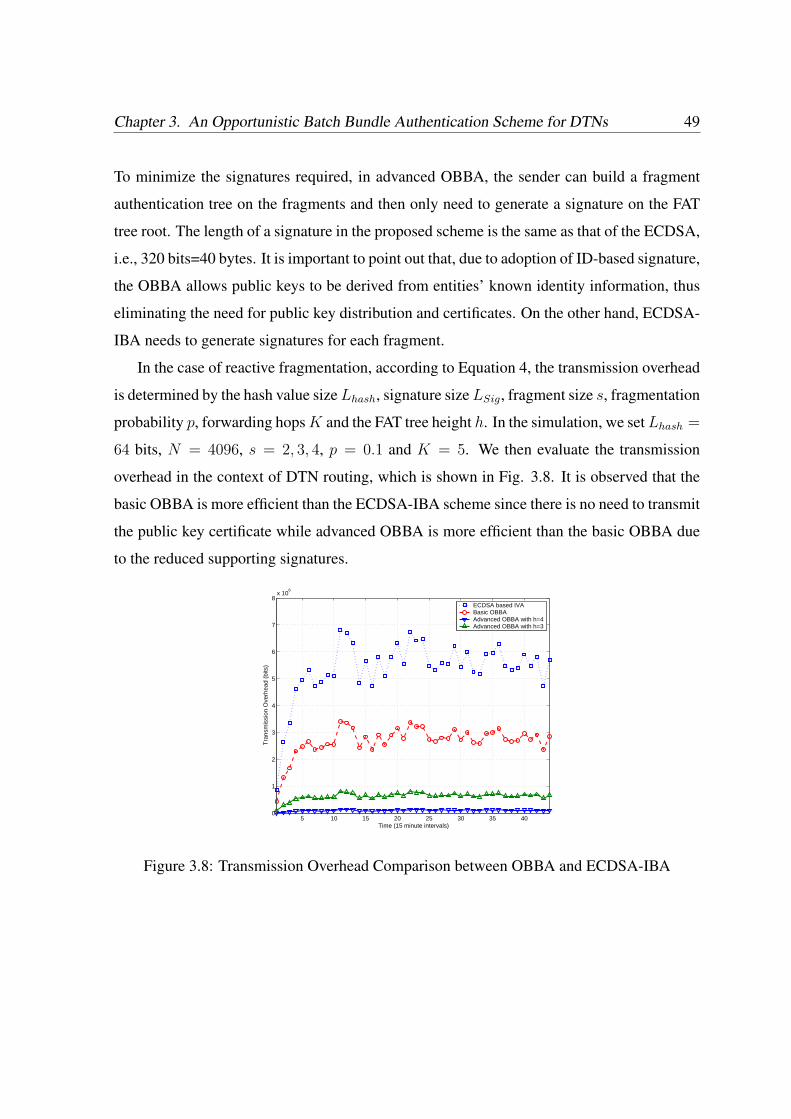
Chapter 3. An Opportunistic Batch Bundle Authentication Scheme for DTNs 49
To minimize the signatures required, in advanced OBBA, the sender can build a fragment
authentication tree on the fragments and then only need to generate a signature on the FAT
tree root. The length of a signature in the proposed scheme is the same as that of the ECDSA,
i.e., 320 bits=40 bytes. It is important to point out that, due to adoption of ID-based signature,
the OBBA allows public keys to be derived from entities’ known identity information, thus
eliminating the need for public key distribution and certificates. On the other hand, ECDSA-
IBA needs to generate signatures for each fragment.
In the case of reactive fragmentation, according to Equation 4, the transmission overhead
is determined by the hash value size Lhash, signature size LSig, fragment size s, fragmentation
probability p, forwarding hops K and the FAT tree height h. In the simulation, we set Lhash =
64 bits, N = 4096, s = 2, 3, 4, p = 0.1 and K = 5. We then evaluate the transmission
overhead in the context of DTN routing, which is shown in Fig. 3.8. It is observed that the
basic OBBA is more efficient than the ECDSA-IBA scheme since there is no need to transmit
the public key certificate while advanced OBBA is more efficient than the basic OBBA due
to the reduced supporting signatures.
5 10 15 20 25 30 35 400
1
2
3
4
5
6
7
8x 10
6
Time (15 minute intervals)
Tra
nsm
issi
on O
verh
ead
(bits
)
ECDSA based IVABasic OBBAAdvanced OBBA with h=4Advanced OBBA with h=3
Figure 3.8: Transmission Overhead Comparison between OBBA and ECDSA-IBA
Security in Delay Tolerant Networks 50
3.4.4 Energy Consumption
Energy consumption is a major concern for DTN security design since the DTN nodes are
typically battery-powered devices such as cell phones and laptop computers. The energy
consumption incurred by bundle authentication includes both the computational energy cost
and transmission energy cost. As for the transmission energy consumption, as reported in
[42], a Chipcon CC1000 radio used in Crossbow MICA2DOT motes consumes 28.6 and 59.2
µJ to receive and transmit one byte, respectively. Therefore, we can obtain the transmission
energy cost for each bytes per hop as (28.6 + 59.2) µJ .
As for the computational energy consumption, according to [43], the computation of the
Tate pairing on PXA255 roughly needs the energy consumption 25.5 mJ. Due to the batch
bundle authentication, the energy consumption of signature verification can be defined as
25.5 ∗ 2 mJ. For the ECDSA-IBA scheme, as reported in [42], it takes 92.4 mJ to verify an
ECDSA-160 signature. By jointly considering the transmission and computational overhead,
we obtain the simulation results on energy consumption for each bundle propagation and en-
route authentication in Fig. 3.9. It is observed that the energy consumptions incurred by
basic OBBA and advanced OBBA are still much less that that of ECDSA-IBA. This further
demonstrates the effectiveness of the proposed OBBA scheme.
3.5 Summary
In this Chapter, by exploiting the unique bundle buffering characteristic, we have proposed an
efficient batch bundle authentication scheme for DTNs to effectively reduce the transmission
cost as well as computational cost. Our future research includes studying a more advanced
fragmentation model and its impact on the proposed OBBA scheme. We will also investigate
other security issues related to DTN routing.
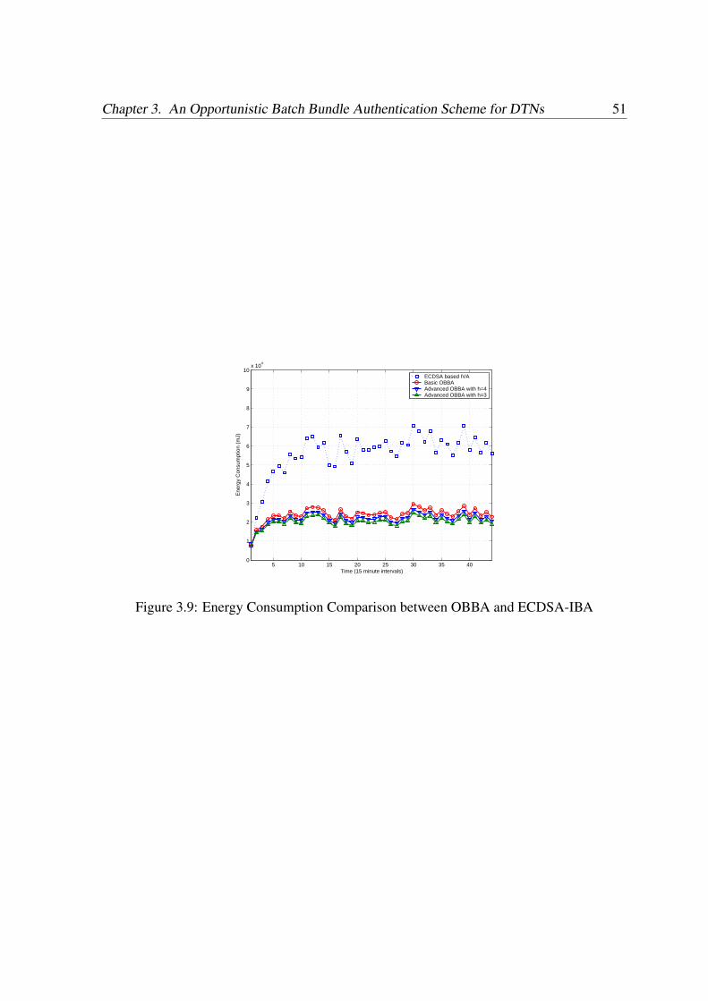
Chapter 3. An Opportunistic Batch Bundle Authentication Scheme for DTNs 51
5 10 15 20 25 30 35 400
1
2
3
4
5
6
7
8
9
10x 10
4
Time (15 minute intervals)
Ene
rgy
Con
sum
ptio
n (m
J)
ECDSA based IVABasic OBBAAdvanced OBBA with h=4Advanced OBBA with h=3
Figure 3.9: Energy Consumption Comparison between OBBA and ECDSA-IBA

Chapter 4
A Secure Multi-Layer Credit-based
Incentive Scheme for DTNs
In this chapter, we will focus on how to thwart selfishness issues. Previously reported stud-
ies have focused on opportunistic data propagation in DTNs [15–19], which depends on the
hypothesis that each individual node is ready to forward packets for others. This hypothesis,
however, might be easily violated in the presence of selfish nodes or even malicious ones,
which may choose to save their precious wireless resources by refusing to serve as bundle
relays [45]. Such selfishness actions may be more challenging for researchers in certain ap-
plications of DTNs such as vehicular DTNs and social networks, which are decentralized
and distributed over a multitude of devices that are controlled and operated by individuals.
In these applications, it is highly possible that there exist some selfish users who may not
want to forward such bundles without compensation. Further, even from the security point of
view, naive packet forwarding may open a new door for malicious users, who may intention-
ally try to launch Denial-of-Service (DoS) attacks on the network by flooding the network
with dummy messages. Thus, to deploy an applicable delay tolerant network in real-world
scenarios, proper incentives and security mechanisms should be in place.
One of the most promising ways to address the selfishness issue and stimulate coopera-
52
Chapter 4. A Secure Multi-Layer Credit-based Incentive Scheme for DTNs 53
tion among selfish nodes in DTNs is using incentive schemes, which basically fall into two
categories: reputation-based or credit-based schemes. Reputation-based schemes rely on in-
dividual nodes to monitor neighboring nodes’ traffic and keep track of each others’ reputation
so that uncooperative nodes are eventually detected and excluded from the networks [45–48],
while credit-based schemes introduce some form of virtual currency to regulate the packet-
forwarding relationships among different nodes [49–51]. The previously reported incentive
schemes, which were proposed for conventional mobile ad hoc networks, may not be suit-
able for DTNs, for the following two reasons. Firstly, a common assumption adopted in
existing incentive schemes is that a full end-to-end path between source and destination can
be determined before data forwarding occurs. This assumption does not hold in DTNs due
to its intrinsic opportunistic forwarding nature. Secondly, the reported schemes are designed
mainly for single copy forwarding. However, multi-copy forwarding or even flooding is often
adopted to enhance the reliability of DTN communication [15], which makes most existing
incentive schemes incompatible with diverse DTN routing.
In this paper, we propose a Secure Multi-Layer Credit-based Incentive (SMART) scheme
for DTNs afflicted with selfish nodes. Similar to other credit based incentive schemes,
SMART uses credits to provide incentive to selfish nodes. However, one of its novel and
distinguishing features is that SMART allows the credit to be transferred/distributed by the
current intermediate node without the involvement of the sender. Such a design is well suited
for DTNs since, in DTNs, the bundle sender cannot predict the bundle forwarding path and
intermediate nodes may also suffer from delayed or frequent loss of connectivity to the bun-
dle sender.
In specific, SMART is based on the notion of a layered coin that provides virtual elec-
tronic credits to charge for and reward the provision of data forwarding in DTNs. Such a
coin is comprised of multiple layers, each of which is generated by the source/destination or
an intermediate node. The first layer, also named the base layer, is generated by the source
to indicate payment rate (credit value), remuneration conditions, class of service (CoS) re-

Security in Delay Tolerant Networks 54
quirement, and other reward policies. During the subsequent bundle propagation process,
each intermediate node will generate a new layer based on the previous layers by appending
a non-forgeable digital signature. This new layer is also called the endorsed layer, which
implies that the forwarding node agrees to provide forwarding service under the predefined
CoS requirement and will be rewarded according to the reward policy in the future. With en-
dorsed layers, it is easy to track the propagation path and determine each intermediate node
by checking the signature of each endorsed layer. In the rewarding and charging phase, if the
provided forwarding service satisfies remuneration conditions defined in the predefined re-
ward policy, each forwarding node along one or multiple path(s) will share the credit defined
in this coin depending on different data forwarding algorithms (single-copy/multi-copying
forwarding) and the actual forwarding results (bundle delivered along one or multiple paths).
However, the main challenge in designing the SMART is to ensure that the security prop-
erties of the scheme are not compromised. Since all security related to a coin, especially
during the store-carry-and-forward process, is managed by the intermediate nodes, a selfish
node (or even a group of colluding nodes) may attempt to cheat the system to maximize its
expected welfare. As an example, a selfish node may arbitrarily inject a fake layer into the
current coin or remove several valid layers from it, if such actions can maximize its wel-
fare. This is the security perspective of SMART. Secondly, any security functionality will
incur extra computation and transmission overhead. A secure credit-based incentive scheme
should be efficient enough to not significantly compromise the system performance. This is
the performance perspective of our system.
The contributions of this paper can be summarized as follows. Firstly, we propose a se-
cure multi-layer credit-based incentive scheme to stimulate cooperation among selfish nodes
in DTNs. The proposed scheme can be made compatible to diverse data-forwarding algo-
rithms in DTNs. Secondly, SMART can withstand a wide range of cheating actions be-
cause of its novel layer concatenation technique. Thirdly, we propose two performance-
optimization techniques to minimize the computation and transmission overhead. Further,
Chapter 4. A Secure Multi-Layer Credit-based Incentive Scheme for DTNs 55
SMART is a one-way, non-interactive protocol, which is particularly suitable for DTNs,
where interactive communication suffers from long round-trip delays and frequent discon-
nection [25]. Lastly, extensive simulations are conducted to demonstrate the efficiency and
effectiveness of the proposed SMART scheme.
The remainder of the paper is organized as follows. Section 4.1 provides a comprehensive
overview of related work. In Section 4.2, we present the system model, node model, and the
design goals. In Section 4.3, we first give an overview of SMART scheme and then present
SMART in detail as well as two performance optimization methods. Performance evaluation
is given in Section 4.4, followed by the discussion and conclusion in Section 4.5 and 4.6,
respectively.
4.1 Related Work
There is a large amount of literature on incentive mechanisms for different kinds of networks.
These reported mechanisms basically fall into two categories: reputation-based schemes and
credit-based schemes.
Reputation-based schemes rely on the individual nodes to monitor neighboring nodes’
traffic and keep track of each others’ reputation so that uncooperative nodes can eventually
be detected and excluded from the networks [45–48]. However, in DTNs, existing reputation
based incentive schemes may face the challenge of indistinguishability of sending and no
sending a message, since the data forwarding cannot be observed during the store-carry-and-
forward process. Further, it is also challenging to efficiently and effectively propagate the
reputation.
Credit-based incentive schemes introduce some form of virtual currency to regulate the
packet-forwarding relationships among different nodes. There are two different ways to re-
alize such kind of credits: game theory based schemes and security protocol based schemes.
The first approach try to investigate such non-cooperative communication scenarios within a
Security in Delay Tolerant Networks 56
game theory framework [53–55] while the second approach focuses on ensuring the security
of the credits by using various cryptographic tools [49, 51]. Most of these schemes always
assume that an end-to-end path exists and is determined before the data forwarding process.
However, this assumption obviously does not hold in DTNs, which makes them not suitable
in DTNs. In [50], a virtual cash based incentive scheme are proposed to stimulate commercial
advertisement dissemination in vehicular networks. In [52], it is suggested to use multilevel
coupon based scheme to stimulate exchanging information about places of interest or local
restaurants. However, in both of schemes, the focus is how to stimulate the advertisement
dissemination and transmission is based on simple broadcasting while the DTN routing is
not taken into consideration.
We incorporate a secure credit based incentive scheme into the DTN data routing/forwarding,
which distinguish SMART from previous work. The existing routing or data forwarding
schemes in DTN can be categorized into single copy scheme and multi-copy scheme. Some
protocols (e.g., First Contact [17] and Direct Transmission/Delivery [16]) generate just a sin-
gle copy, others enable the source to limit the forwarding copies to a fixed number [15] while
epidemic [18] and probabilistic routing [19] potentially create an “infinite” number of mes-
sages. A latest study shows that, even though single-copy schemes can considerably reduce
resource waste, they are often be orders of magnitude slower than multi-copy algorithms and
are inherently less reliable [15]. Therefore, in this study, we consider a generalized multi-
copy data forwarding scheme as the foundation and therefore our SMART can be made
compatible to diverse multi-copy data forwarding schemes.
4.2 System Model and Design Goals
This section describes our system model and design goals.
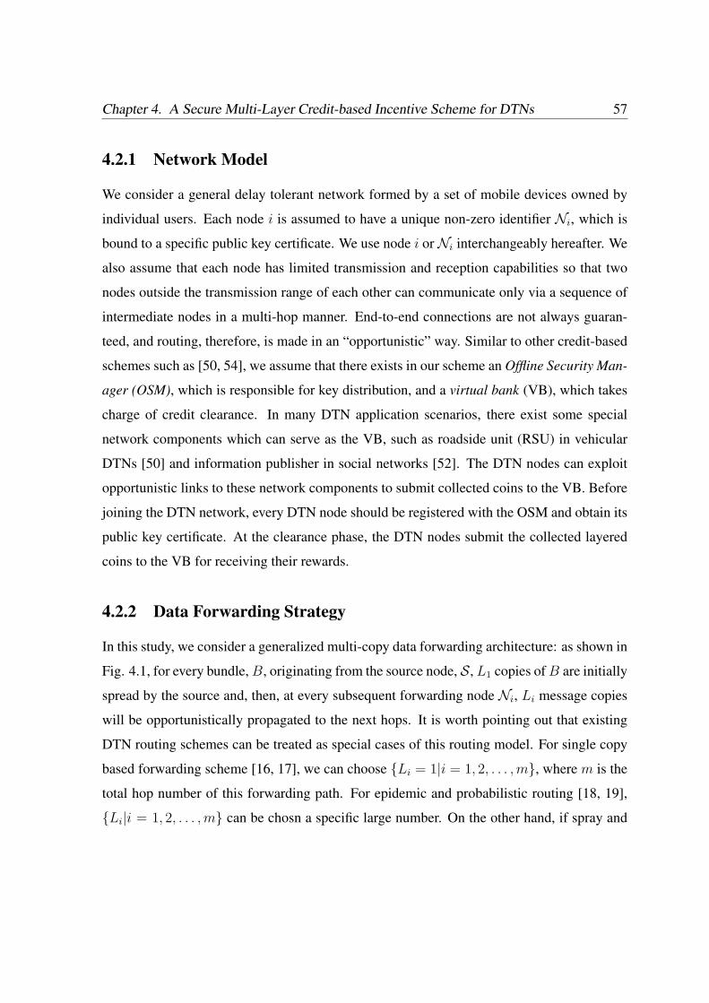
Chapter 4. A Secure Multi-Layer Credit-based Incentive Scheme for DTNs 57
4.2.1 Network Model
We consider a general delay tolerant network formed by a set of mobile devices owned by
individual users. Each node i is assumed to have a unique non-zero identifier Ni, which is
bound to a specific public key certificate. We use node i orNi interchangeably hereafter. We
also assume that each node has limited transmission and reception capabilities so that two
nodes outside the transmission range of each other can communicate only via a sequence of
intermediate nodes in a multi-hop manner. End-to-end connections are not always guaran-
teed, and routing, therefore, is made in an “opportunistic” way. Similar to other credit-based
schemes such as [50, 54], we assume that there exists in our scheme an Offline Security Man-
ager (OSM), which is responsible for key distribution, and a virtual bank (VB), which takes
charge of credit clearance. In many DTN application scenarios, there exist some special
network components which can serve as the VB, such as roadside unit (RSU) in vehicular
DTNs [50] and information publisher in social networks [52]. The DTN nodes can exploit
opportunistic links to these network components to submit collected coins to the VB. Before
joining the DTN network, every DTN node should be registered with the OSM and obtain its
public key certificate. At the clearance phase, the DTN nodes submit the collected layered
coins to the VB for receiving their rewards.
4.2.2 Data Forwarding Strategy
In this study, we consider a generalized multi-copy data forwarding architecture: as shown in
Fig. 4.1, for every bundle, B, originating from the source node, S, L1 copies of B are initially
spread by the source and, then, at every subsequent forwarding node Ni, Li message copies
will be opportunistically propagated to the next hops. It is worth pointing out that existing
DTN routing schemes can be treated as special cases of this routing model. For single copy
based forwarding scheme [16, 17], we can choose Li = 1|i = 1, 2, . . . , m, where m is the
total hop number of this forwarding path. For epidemic and probabilistic routing [18, 19],
Li|i = 1, 2, . . . , m can be chosn a specific large number. On the other hand, if spray and

Security in Delay Tolerant Networks 58
waiting routing scheme is chosen as the basic data forwarding scheme [15], we can assume
L1 = L,Li = 1|i = 2, . . . , m, where L is the the total forwarding copy number.
S Ni+1Ni
i-th Forwarding
Node Set
N1
First Forwarding
Node Set
D
Source Node Destination
Node
i+1-th Forwarding
Node Set
Opportunistic Link
Figure 4.1: A Generalized Data Forwarding Strategy
4.2.3 Rewarding Model
There are several available rewarding models which can be adopted in SMART. For example,
a popular charging method in [49] is paying per packet, which means for each successfully
transmitted unit-sized packet, each of N intermediate nodes should receive λ credits, while
the source needs to pay λ ∗ N in total. However, we argue that this method is not suitable
for opportunistic data forwarding in that it is difficult for the source to predict how many
copies or hops are needed to successfully deliver a message to the destination. Therefore,
in this study, we consider a profit sharing model, which means that the intermediate nodes
involved in a successfully bundle delivery will be paid with a dividend of the total credit
provided by the source node. The source node can also specify a diverse, case-by-case basis
rewarding requirements in the base layer of a layered coin, which can be regarded as a part
of DTN routing policy [26]. For example, a bundle should be successfully delivered within a
particular TTL (Time-to-live) period or only the intermediate nodes along first successfully
delivery path can be remunerated. The study on rewarding policy is still an open problem
Chapter 4. A Secure Multi-Layer Credit-based Incentive Scheme for DTNs 59
and therefore deserves more investigation in the future incentive related research.
4.2.4 Attack Model
Due to the selfish nature, mobile nodes will try to cheat the system to maximize their welfare.
In particular, a selfish node can exhibit one of the three following selfish actions:
1. Credit Forgery Attack (or Layer Injection Attack:) A selfish node may attempt to
forge a valid credit (e.g. collude with other nodes to inject non-existent layers into a
valid layered coin) to reward itself for work it did not do or for more than it has done.
2. Nodular Tontine Attack (or Layer Removal Attack:) Unlike in a layer injection
attack, when receiving a multi-level credit, a selfish node may try to remove one or
several existing layers which have been generated by the previous forwarding nodes.
This attack is particularly effective in profit-sharing systems, where the profits of the
removed nodes will be shared by the remaining nodes. In this sense, it is similar to
a tontine system1, in which participants share a common fund and have been known
to try to kill each other off, thereby increasing their shares. Therefore, we denote this
kind of attack as a nodular tontine attack.
3. Submission Refusal Attack: In DTNs, due to the lack of end-to-end connection,
a source node as well as other intermediate nodes may not have a clear idea about
the forwarding progress and thus it relies on the last forwarding node to submit the
generated layered coins to a VB for clearance. However, if colluding with the source
1The tontine is named after Lorenzo Tonti, a Neapolitan banker who started such a scheme in France in
1653. In a tontine system, each subscriber paid a sum into the fund, and in return received dividends from the
capital invested; as each person died his share was divided among all the others until only one was left, reaping
all the benefits. Since there was too much incentive for subscribers to bump each other off to increase their share
of the fund, or to become the last survivor and so claim the capital, it’s a wonderful plot device for detective
story writers, who can use it as a motive for serial murder. [http://www.worldwidewords.org/weirdwords/ww-
ton1.htm]
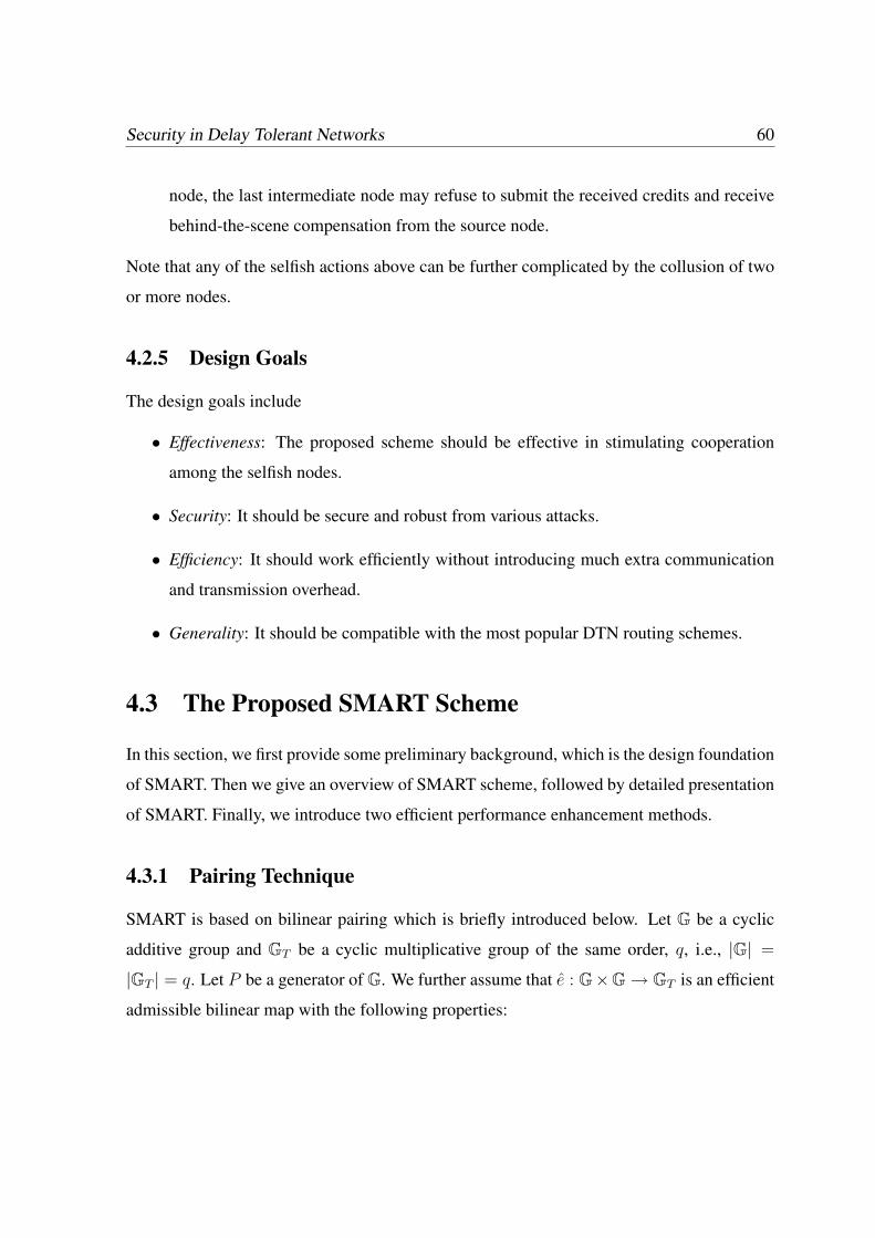
Security in Delay Tolerant Networks 60
node, the last intermediate node may refuse to submit the received credits and receive
behind-the-scene compensation from the source node.
Note that any of the selfish actions above can be further complicated by the collusion of two
or more nodes.
4.2.5 Design Goals
The design goals include
• Effectiveness: The proposed scheme should be effective in stimulating cooperation
among the selfish nodes.
• Security: It should be secure and robust from various attacks.
• Efficiency: It should work efficiently without introducing much extra communication
and transmission overhead.
• Generality: It should be compatible with the most popular DTN routing schemes.
4.3 The Proposed SMART Scheme
In this section, we first provide some preliminary background, which is the design foundation
of SMART. Then we give an overview of SMART scheme, followed by detailed presentation
of SMART. Finally, we introduce two efficient performance enhancement methods.
4.3.1 Pairing Technique
SMART is based on bilinear pairing which is briefly introduced below. Let G be a cyclic
additive group and GT be a cyclic multiplicative group of the same order, q, i.e., |G| =
|GT | = q. Let P be a generator of G. We further assume that e : G×G→ GT is an efficient
admissible bilinear map with the following properties:
Chapter 4. A Secure Multi-Layer Credit-based Incentive Scheme for DTNs 61
• Bilinear: for a, b ∈ Z∗q , e(aP, bP ) = e(P, P )ab.
• Non-degenerate: e(P, P ) 6= 1GT.
• Computable: there is an efficient algorithm to compute e(P1, Q1) for any P1, Q1 ∈ G.
According to [34], such an admissible bilinear map e can be constructed by Weil or Tate
pairings on the elliptic curves.
4.3.2 The Overview of SMART
Before presenting our SMART scheme, we first introduce a naive multi-layer coin scheme.
In such a naive scheme, the data forwarding process can also be regarded as a layered coin
generation process. When a node sends its own messages, the node will lose credit (or
virtual money) to the network because other nodes incur a cost to forward the messages. The
bundle sender first generates the base layer of a layered coin and then sends it together with
the original bundles to a certain number of downlink nodes. At each subsequent hop, each
intermediate node generates a new endorsed layer based on the previous layered coin. It
is obvious that with layered coins each hop of a successful data-forwarding process can be
easily tracked. After that, each intermediate node periodically submits its collected layered
coins to the VB, which can calculate credits for each intermediate node and also make a
charge on the bundle senders. Note that, since only the nodes on the successful delivery
path are rewarded, each intermediate node can launch different kinds of attacks on this naive
system. In the following sections, we progressively determine what SMART needs in order
to prevent the various attacks.
Preventing Layer Injection or Nodular Tontine Attack
Layer injection attack and nodular tontine attack are two ways to cheat the SMART. In a
layer injection attack, several nodes may collude with each other to cheat extra credits. We
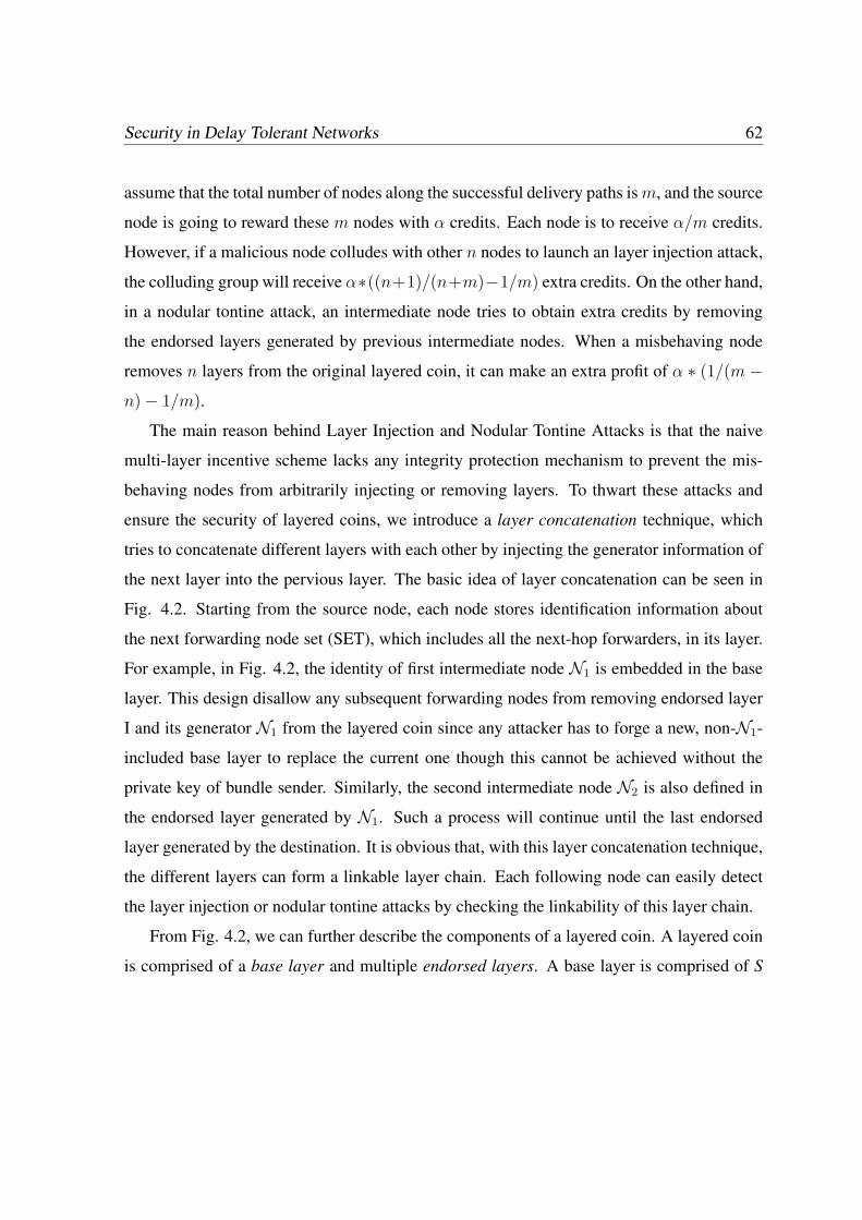
Security in Delay Tolerant Networks 62
assume that the total number of nodes along the successful delivery paths is m, and the source
node is going to reward these m nodes with α credits. Each node is to receive α/m credits.
However, if a malicious node colludes with other n nodes to launch an layer injection attack,
the colluding group will receive α∗((n+1)/(n+m)−1/m) extra credits. On the other hand,
in a nodular tontine attack, an intermediate node tries to obtain extra credits by removing
the endorsed layers generated by previous intermediate nodes. When a misbehaving node
removes n layers from the original layered coin, it can make an extra profit of α ∗ (1/(m −n)− 1/m).
The main reason behind Layer Injection and Nodular Tontine Attacks is that the naive
multi-layer incentive scheme lacks any integrity protection mechanism to prevent the mis-
behaving nodes from arbitrarily injecting or removing layers. To thwart these attacks and
ensure the security of layered coins, we introduce a layer concatenation technique, which
tries to concatenate different layers with each other by injecting the generator information of
the next layer into the pervious layer. The basic idea of layer concatenation can be seen in
Fig. 4.2. Starting from the source node, each node stores identification information about
the next forwarding node set (SET), which includes all the next-hop forwarders, in its layer.
For example, in Fig. 4.2, the identity of first intermediate node N1 is embedded in the base
layer. This design disallow any subsequent forwarding nodes from removing endorsed layer
I and its generator N1 from the layered coin since any attacker has to forge a new, non-N1-
included base layer to replace the current one though this cannot be achieved without the
private key of bundle sender. Similarly, the second intermediate node N2 is also defined in
the endorsed layer generated by N1. Such a process will continue until the last endorsed
layer generated by the destination. It is obvious that, with this layer concatenation technique,
the different layers can form a linkable layer chain. Each following node can easily detect
the layer injection or nodular tontine attacks by checking the linkability of this layer chain.
From Fig. 4.2, we can further describe the components of a layered coin. A layered coin
is comprised of a base layer and multiple endorsed layers. A base layer is comprised of S
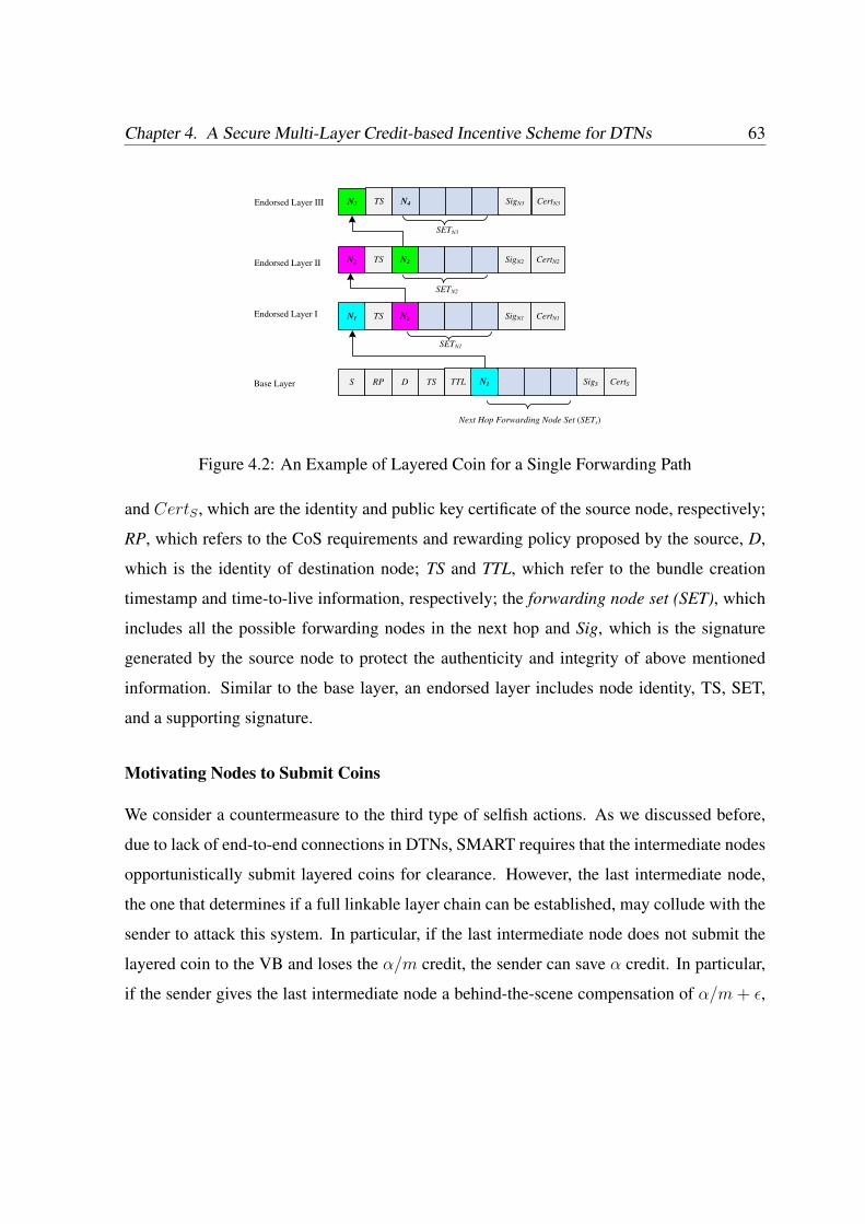
Chapter 4. A Secure Multi-Layer Credit-based Incentive Scheme for DTNs 63
Endorsed Layer I
Endorsed Layer II
Endorsed Layer III
Base Layer
Next Hop Forwarding Node Set (SETs)
SETN1
SETN2
SETN3
S RP D TS TTL SigS CertS
TS N2 SigN1 CertN1
N2 TS N2 SigN2 CertN2
N3 TS N4 SigN3 CertN3
N1
N1
Figure 4.2: An Example of Layered Coin for a Single Forwarding Path
and CertS , which are the identity and public key certificate of the source node, respectively;
RP, which refers to the CoS requirements and rewarding policy proposed by the source, D,
which is the identity of destination node; TS and TTL, which refer to the bundle creation
timestamp and time-to-live information, respectively; the forwarding node set (SET), which
includes all the possible forwarding nodes in the next hop and Sig, which is the signature
generated by the source node to protect the authenticity and integrity of above mentioned
information. Similar to the base layer, an endorsed layer includes node identity, TS, SET,
and a supporting signature.
Motivating Nodes to Submit Coins
We consider a countermeasure to the third type of selfish actions. As we discussed before,
due to lack of end-to-end connections in DTNs, SMART requires that the intermediate nodes
opportunistically submit layered coins for clearance. However, the last intermediate node,
the one that determines if a full linkable layer chain can be established, may collude with the
sender to attack this system. In particular, if the last intermediate node does not submit the
layered coin to the VB and loses the α/m credit, the sender can save α credit. In particular,
if the sender gives the last intermediate node a behind-the-scene compensation of α/m + ε,
Security in Delay Tolerant Networks 64
where ε > 0, the last node will be better off while the sender still enjoys a net gain of
α∗ (1−1/m)− ε. However, the other nodes except the sender and the last intermediate node
will receive nothing, which may lead to a serious fairness issue.
In order to prevent this cheating action, we propose two strategies to discourage the bun-
dle sender from colluding with the last forwarding node. The first is a charge-model based
solution [54]. For every forwarding request, SMART requires that the VB charges the sender
an extra amount of credit, α, even if the last intermediate node does not submit the layered
coins for clearance. This extra charge is reasonable since, even though it seems no successful
delivery path exists, this data forwarding still incurs forwarding costs to all the forwarding
nodes involved. This extra charge goes to the VB, which either keeps it or returns the credit
back to the involved forwarding nodes uniformly. Given such extra charges, even a colluding
group cannot benefit from this cheating action.
SMART can also reduce the risk of the submission refusal attack by using multiple copy
forwarding. We assume that the source node colludes with na forwarding nodes to launch a
submission refusal attack. Let nc denote the number of copies transmitted for each message,
and d refer to the average number of one-hop neighbors of a DTN node. To maximize the
attacking effect, we consider that all of the colluding nodes are located in the destination’s
transmission range. Given this setting, the probability of successful launching a submission
refusal attack can be defined as the probability that every successful delivery path is con-
trolled by the colluding nodes. In other words, the probability of successful defending a
submission refusal attack (or SR rate) as the probability that at least one forwarding path
does not involve any colluding nodes. SR can be computed with the following equation:
FI =
1−nc∏i=1
na−i+1d−i+1
, if nc ≤ na
1 , if nc > na
(4.1)
Fig 4.3 shows the SR under different nc, d, and na values. We notice that SR grows
very quickly when nc increases. For example, when d = 15, na = 9, and nc = 5, SR
is approximately 95.8%. Therefore, depending on the level of security required and the
Chapter 4. A Secure Multi-Layer Credit-based Incentive Scheme for DTNs 65
1 1.5 2 2.5 3 3.5 4 4.5 50
0.1
0.2
0.3
0.4
0.5
0.6
0.7
0.8
0.9
1
nc−−the number of forwarding copy
The
pro
pabi
lity
of a
t lea
st o
ne n
on−
com
prom
ised
pat
h
d=15,na=9
d=15,na=7
d=15,na=6
d=15,na=5
Figure 4.3: The Probability of Existing at Least A Non-compromised Path under Different
nc
potential number of colluding nodes in the network, OSM can find an optimal nc that achieves
a good balance between security and efficiency.
4.3.3 The SMART Scheme
In this subsection, we present the details of SMART scheme, which includes “System Initial-
ization,” “Bundle Generation,” “Bundle Forwarding,” and “Charging and Rewarding” steps.
System Initialization
OSM adopts bilinear pairing system parameters (q,G,GT , e, P ) as the system parameters.
In addition, two hash functions are formed: H : 0, 1∗ → 0, 1∗ and H2 : 0, 1∗ → G.
The system parameters (q,G,GT , e, P, H, H2) will be preloaded in every DTN node. Each
node,N , randomly chooses skN ∈ Z∗q as its private key, which corresponds to the public key
expressed as PKN = skNP . Then it contacts the OSM to obtain its corresponding public

Security in Delay Tolerant Networks 66
key certificate.
Bundle Generation
When a bundle sender, S, is going to send a bundle B to the destination D, after deter-
mining the next hop forwarding node set SETS , S signs on the bundles with its private
keys skS by computing SigS ← skSH2(B||S||RP ||D||TS||TTL||SETS). Here, we use the
Boneh, Lynn and Shacham (BLS) signature [56] as the underlying building block to gener-
ate the supporting signature. Thus, S obtains the base layer as B layer = (S, RP, D, TS,
TTL, SETs, SigS , CertS). Then S forwards the bundle as well as the base layer to the next
forwarding nodes as follows:
S → SETS : B, B Layer
Note that, in a multi-copy opportunistic data forwarding algorithm, a bundle may be for-
warded along with multiple paths. Each forwarding path may form its layered coin even
though the generated coins share a same base layer. Without loss of generality, in the follow-
ing section, we take a single forwarding path S → N1 → N2 → . . .Ni . . . → Nm → D as
an example to show the details of the basic SMART scheme, where Nm represents the last
intermediate node.
Bundle Forwarding
When an intermediate node, Ni, receives the bundle as well as the layered coin which in-
cludes a base layer and multiple endorsed layers, it performs the following steps to authenti-
cate the layered coin:
1. Check if the bundle is in their lifetime.
2. Check the linkability of the layer chains.
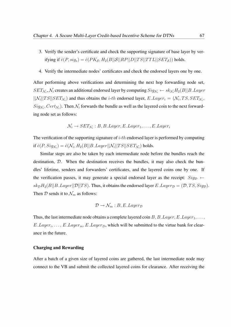
Chapter 4. A Secure Multi-Layer Credit-based Incentive Scheme for DTNs 67
3. Verify the sender’s certificate and check the supporting signature of base layer by ver-
ifying if e(P, sigs) = e(PKS , H2(B||S||RP ||D||TS||TTL||SETS)) holds.
4. Verify the intermediate nodes’ certificates and check the endorsed layers one by one.
After performing above verifications and determining the next hop forwarding node set,
SETNi,Ni creates an additional endorsed layer by computing SigNi
← skNiH2(B||B Layer
||Ni||TS||SETNi) and thus obtains the i-th endorsed layer, E Layeri = (Ni, TS, SETNi
,
SigNi, CertNi
). ThenNi forwards the bundle as well as the layered coin to the next forward-
ing node set as follows:
Ni → SETNi: B, B Layer, E Layer1, . . . , E Layeri
The verification of the supporting signature of i-th endorsed layer is performed by computing
if e(P, SigNi) = e(Ni, H2(B||B Layer||Ni||TS||SETNi
) holds.
Similar steps are also be taken by each intermediate node before the bundles reach the
destination, D. When the destination receives the bundles, it may also check the bun-
dles’ lifetime, senders and forwarders’ certificates, and the layered coins one by one. If
the verification passes, it may generate a special endorsed layer as the receipt: SigD ←skDH2(B||B Layer||D||TS). Thus, it obtains the endorsed layer E LayerD = (D, TS, SigD).
Then D sends it to Nm as follows:
D → Nm : B, E LayerD
Thus, the last intermediate node obtains a complete layered coin B, B Layer, E Layer1, . . . ,
E Layeri, . . . , E Layerm, E LayerD, which will be submitted to the virtue bank for clear-
ance in the future.
Charging and Rewarding
After a batch of a given size of layered coins are gathered, the last intermediate node may
connect to the VB and submit the collected layered coins for clearance. After receiving the

Security in Delay Tolerant Networks 68
submitted layered coins, the VB first checks the certificates of each node in the forwarding
path and then verifies the legitimacy of the layered coins. The VB also check that if these
layered coins have been deposited before by inquiring the sender’s previous record. If all
verifications pass, a predefined amount of the credit will be shared by all of the forwarders
under a particular predefined rewarding policy.
The credit calculation should take bundle fragmentation into consideration. In DTNs,
when a message is large, it may not be possible to send the entire message at once. One
possible solution is to split the message into smaller pieces and let each become its own
bundle, or “fragment bundle”, and send some pieces of a large message through the cur-
rent link and rest of the message through another link later to make the best use of limited
resources. As the general discussion on credit calculation, we assume that there are n inter-
mediate nodes participating in a successful bundle forwarding and each node Ni|1 ≤ i ≤ n
forwards δi percentage of fragments, where 0 < δi ≤ 1. Then, the node Ni will receive
CredNi= α ∗ δi/Σ
nj=1δj credits, where α is the total credits provided by the bundle sender.
4.3.4 Efficiency Enhancement
In this subsection, we propose two methods to further improve the computation and trans-
mission efficiency of the SMART scheme.
Reducing The Transmission And Computation Overhead With Aggregate Signature
The signature transmission and verification contribute to the most of transmission and com-
putation overhead incurred by SMART transmission and verification. Therefore, reducing
the signature size and increasing the verification efficiency is a major concern in the practical
deployment of the SMART scheme. Here, we take the advantage of aggregated signature to
reduce the transmission and verification cost.
An aggregate signature is a digital signature that supports aggregation of n distinct sig-
natures issued by n distinct signers to a single short signature [56]. This single signature
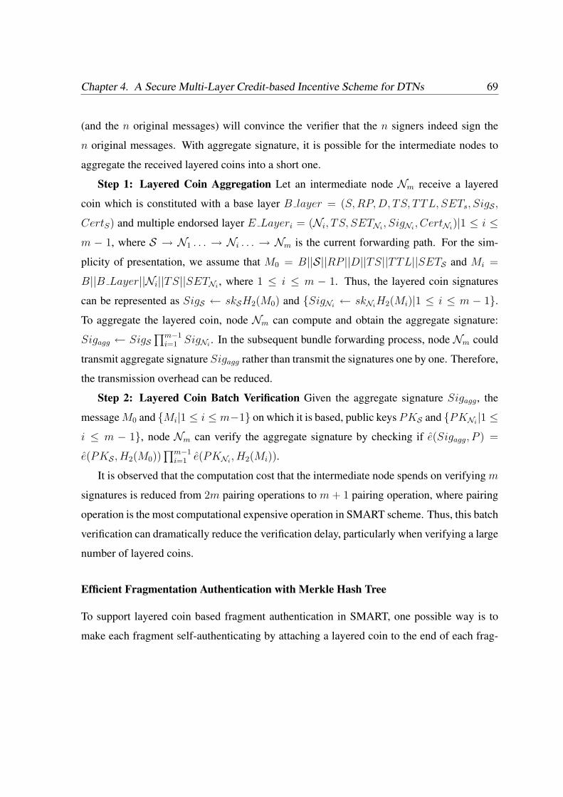
Chapter 4. A Secure Multi-Layer Credit-based Incentive Scheme for DTNs 69
(and the n original messages) will convince the verifier that the n signers indeed sign the
n original messages. With aggregate signature, it is possible for the intermediate nodes to
aggregate the received layered coins into a short one.
Step 1: Layered Coin Aggregation Let an intermediate node Nm receive a layered
coin which is constituted with a base layer B layer = (S, RP, D, TS, TTL, SETs, SigS ,
CertS) and multiple endorsed layer E Layeri = (Ni, TS, SETNi, SigNi
, CertNi)|1 ≤ i ≤
m − 1, where S → N1 . . . → Ni . . . → Nm is the current forwarding path. For the sim-
plicity of presentation, we assume that M0 = B||S||RP ||D||TS||TTL||SETS and Mi =
B||B Layer||Ni||TS||SETNi, where 1 ≤ i ≤ m − 1. Thus, the layered coin signatures
can be represented as SigS ← skSH2(M0) and SigNi← skNi
H2(Mi)|1 ≤ i ≤ m − 1.
To aggregate the layered coin, node Nm can compute and obtain the aggregate signature:
Sigagg ← SigS∏m−1
i=1 SigNi. In the subsequent bundle forwarding process, node Nm could
transmit aggregate signature Sigagg rather than transmit the signatures one by one. Therefore,
the transmission overhead can be reduced.
Step 2: Layered Coin Batch Verification Given the aggregate signature Sigagg, the
message M0 and Mi|1 ≤ i ≤ m−1 on which it is based, public keys PKS and PKNi|1 ≤
i ≤ m − 1, node Nm can verify the aggregate signature by checking if e(Sigagg, P ) =
e(PKS , H2(M0))∏m−1
i=1 e(PKNi, H2(Mi)).
It is observed that the computation cost that the intermediate node spends on verifying m
signatures is reduced from 2m pairing operations to m + 1 pairing operation, where pairing
operation is the most computational expensive operation in SMART scheme. Thus, this batch
verification can dramatically reduce the verification delay, particularly when verifying a large
number of layered coins.
Efficient Fragmentation Authentication with Merkle Hash Tree
To support layered coin based fragment authentication in SMART, one possible way is to
make each fragment self-authenticating by attaching a layered coin to the end of each frag-
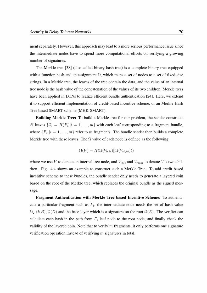
Security in Delay Tolerant Networks 70
ment separately. However, this approach may lead to a more serious performance issue since
the intermediate nodes have to spend more computational efforts on verifying a growing
number of signatures.
The Merkle tree [38] (also called binary hash tree) is a complete binary tree equipped
with a function hash and an assignment Ω, which maps a set of nodes to a set of fixed-size
strings. In a Merkle tree, the leaves of the tree contain the data, and the value of an internal
tree node is the hash value of the concatenation of the values of its two children. Merkle tress
have been applied in DTNs to realize efficient bundle authentication [24]. Here, we extend
it to support efficient implementation of credit-based incentive scheme, or an Merkle Hash
Tree based SMART scheme (MHK-SMART).
Building Merkle Tree: To build a Merkle tree for our problem, the sender constructs
N leaves Ωi = H(Fi)|i = 1, . . . , m with each leaf corresponding to a fragment bundle,
where Fi, |i = 1, . . . , m refer to m fragments. The bundle sender then builds a complete
Merkle tree with these leaves. The Ω value of each node is defined as the following:
Ω(V ) = H(Ω(Vleft)||Ω(Vright)))
where we use V to denote an internal tree node, and Vleft and Vright to denote V ’s two chil-
dren. Fig. 4.4 shows an example to construct such a Merkle Tree. To add credit based
incentive scheme to these bundles, the bundle sender only needs to generate a layered coin
based on the root of the Merkle tree, which replaces the original bundle as the signed mes-
sage.
Fragment Authentication with Merkle Tree based Incentive Scheme: To authenti-
cate a particular fragment such as F1, the intermediate node needs the set of hash value
Ω2, Ω(B), Ω(D) and the base layer which is a signature on the root Ω(E). The verifier can
calculate each hash in the path from F1 leaf node to the root node, and finally check the
validity of the layered coin. Note that to verify m fragments, it only performs one signature
verification operation instead of verifying m signatures in total.

Chapter 4. A Secure Multi-Layer Credit-based Incentive Scheme for DTNs 71
21 43 65 87
A B
C D
F1 F2 F3 F4 F5 F6 F7 F8
i=H(Fi), for i=1, … ,N
(C)=H( (A)|| (B))
(A)=H( 1|| 2)
E: (E)=H( (C)|| (D))
Generate a layered coin based
on Merkle tree root (E)
Figure 4.4: An Example of Merkle Tree Building
4.4 Performance Evaluation
In this section, we evaluate the performance of SMART from several aspects. Our evalu-
ation starts with the cryptographic cost evaluation, which summarizes the computation and
transmission cost incurred by the cryptographic operations in SMART scheme. Then, by
considering cryptographic cost as the system parameter, we further demonstrate the effec-
tiveness and efficiency of SMART in stimulating selfish nodes with extensive simulations.
The evaluated schemes include the basic SMART, Agg-SMART and MKH-SMART. Note
that, Agg-SMART and MKH-SMART can be jointly considered in simulation as Optimized
SMART.
4.4.1 Cryptographic Overhead Evaluation
Communication Overhead
One of the major advantages of SMART is the reduction of transmission cost. It is observed
that the communication cost of layered coin is dominated by the size of supporting signatures
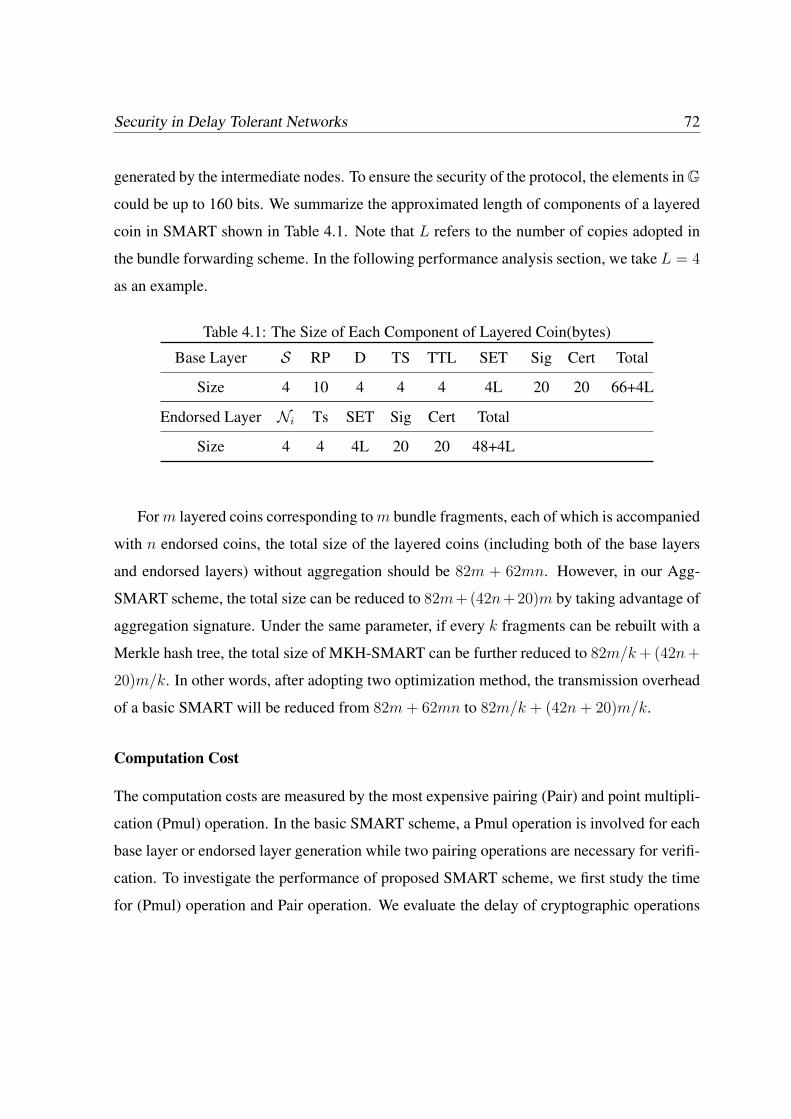
Security in Delay Tolerant Networks 72
generated by the intermediate nodes. To ensure the security of the protocol, the elements inG
could be up to 160 bits. We summarize the approximated length of components of a layered
coin in SMART shown in Table 4.1. Note that L refers to the number of copies adopted in
the bundle forwarding scheme. In the following performance analysis section, we take L = 4
as an example.
Table 4.1: The Size of Each Component of Layered Coin(bytes)
Base Layer S RP D TS TTL SET Sig Cert Total
Size 4 10 4 4 4 4L 20 20 66+4L
Endorsed Layer Ni Ts SET Sig Cert Total
Size 4 4 4L 20 20 48+4L
For m layered coins corresponding to m bundle fragments, each of which is accompanied
with n endorsed coins, the total size of the layered coins (including both of the base layers
and endorsed layers) without aggregation should be 82m + 62mn. However, in our Agg-
SMART scheme, the total size can be reduced to 82m+(42n+20)m by taking advantage of
aggregation signature. Under the same parameter, if every k fragments can be rebuilt with a
Merkle hash tree, the total size of MKH-SMART can be further reduced to 82m/k + (42n +
20)m/k. In other words, after adopting two optimization method, the transmission overhead
of a basic SMART will be reduced from 82m + 62mn to 82m/k + (42n + 20)m/k.
Computation Cost
The computation costs are measured by the most expensive pairing (Pair) and point multipli-
cation (Pmul) operation. In the basic SMART scheme, a Pmul operation is involved for each
base layer or endorsed layer generation while two pairing operations are necessary for verifi-
cation. To investigate the performance of proposed SMART scheme, we first study the time
for (Pmul) operation and Pair operation. We evaluate the delay of cryptographic operations
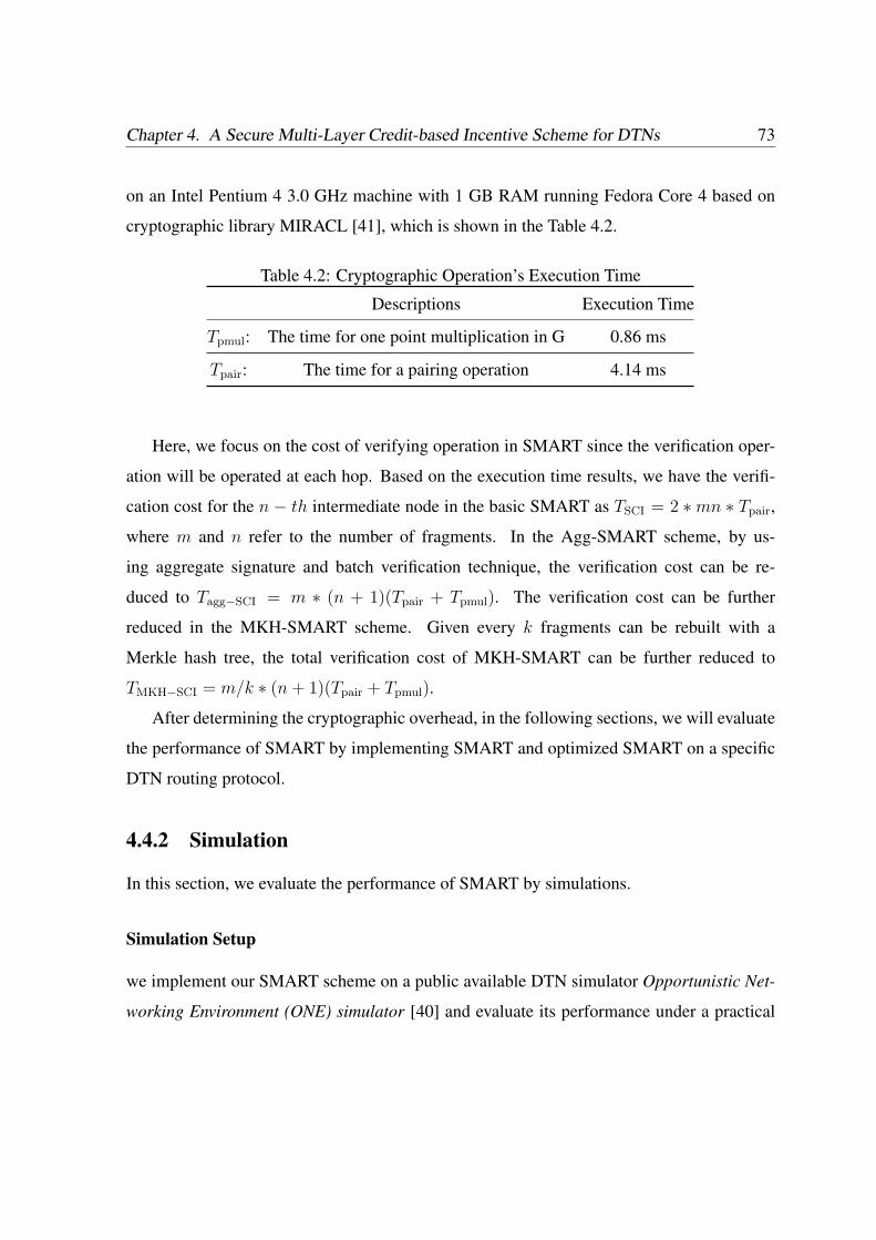
Chapter 4. A Secure Multi-Layer Credit-based Incentive Scheme for DTNs 73
on an Intel Pentium 4 3.0 GHz machine with 1 GB RAM running Fedora Core 4 based on
cryptographic library MIRACL [41], which is shown in the Table 4.2.
Table 4.2: Cryptographic Operation’s Execution Time
Descriptions Execution Time
Tpmul: The time for one point multiplication in G 0.86 ms
Tpair: The time for a pairing operation 4.14 ms
Here, we focus on the cost of verifying operation in SMART since the verification oper-
ation will be operated at each hop. Based on the execution time results, we have the verifi-
cation cost for the n − th intermediate node in the basic SMART as TSCI = 2 ∗mn ∗ Tpair,
where m and n refer to the number of fragments. In the Agg-SMART scheme, by us-
ing aggregate signature and batch verification technique, the verification cost can be re-
duced to Tagg−SCI = m ∗ (n + 1)(Tpair + Tpmul). The verification cost can be further
reduced in the MKH-SMART scheme. Given every k fragments can be rebuilt with a
Merkle hash tree, the total verification cost of MKH-SMART can be further reduced to
TMKH−SCI = m/k ∗ (n + 1)(Tpair + Tpmul).
After determining the cryptographic overhead, in the following sections, we will evaluate
the performance of SMART by implementing SMART and optimized SMART on a specific
DTN routing protocol.
4.4.2 Simulation
In this section, we evaluate the performance of SMART by simulations.
Simulation Setup
we implement our SMART scheme on a public available DTN simulator Opportunistic Net-
working Environment (ONE) simulator [40] and evaluate its performance under a practical
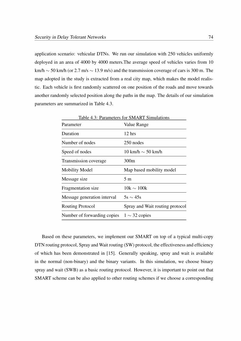
Security in Delay Tolerant Networks 74
application scenario: vehicular DTNs. We run our simulation with 250 vehicles uniformly
deployed in an area of 4000 by 4000 meters.The average speed of vehicles varies from 10
km/h∼ 50 km/h (or 2.7 m/s∼ 13.9 m/s) and the transmission coverage of cars is 300 m. The
map adopted in the study is extracted from a real city map, which makes the model realis-
tic. Each vehicle is first randomly scattered on one position of the roads and move towards
another randomly selected position along the paths in the map. The details of our simulation
parameters are summarized in Table 4.3.
Table 4.3: Parameters for SMART SimulationsParameter Value Range
Duration 12 hrs
Number of nodes 250 nodes
Speed of nodes 10 km/h ∼ 50 km/h
Transmission coverage 300m
Mobility Model Map based mobility model
Message size 5 m
Fragmentation size 10k ∼ 100k
Message generation interval 5s ∼ 45s
Routing Protocol Spray and Wait routing protocol
Number of forwarding copies 1 ∼ 32 copies
Based on these parameters, we implement our SMART on top of a typical multi-copy
DTN routing protocol, Spray and Wait routing (SW) protocol, the effectiveness and efficiency
of which has been demonstrated in [15]. Generally speaking, spray and wait is available
in the normal (non-binary) and the binary variants. In this simulation, we choose binary
spray and wait (SWB) as a basic routing protocol. However, it is important to point out that
SMART scheme can be also applied to other routing schemes if we choose a corresponding
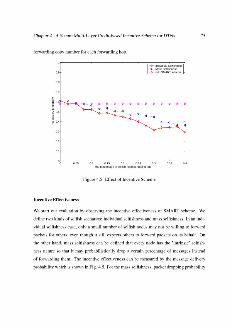
Chapter 4. A Secure Multi-Layer Credit-based Incentive Scheme for DTNs 75
forwarding copy number for each forwarding hop.
0 0.05 0.1 0.15 0.2 0.25 0.3 0.35 0.40
0.1
0.2
0.3
0.4
0.5
0.6
0.7
0.8
0.9
1
The percentage of selfish nodes/dropping rate
The
del
iver
y pr
obab
ility
Individual SelfishnessMass Selfishnesswith SMART scheme
Figure 4.5: Effect of Incentive Scheme
Incentive Effectiveness
We start our evaluation by observing the incentive effectiveness of SMART scheme. We
define two kinds of selfish scenarios: individual selfishness and mass selfishness. In an indi-
vidual selfishness case, only a small number of selfish nodes may not be willing to forward
packets for others, even though it still expects others to forward packets on its behalf. On
the other hand, mass selfishness can be defined that every node has the ’intrinsic’ selfish-
ness nature so that it may probabilistically drop a certain percentage of messages instead
of forwarding them. The incentive effectiveness can be measured by the message delivery
probability which is shown in Fig. 4.5. For the mass selfishness, packet dropping probability
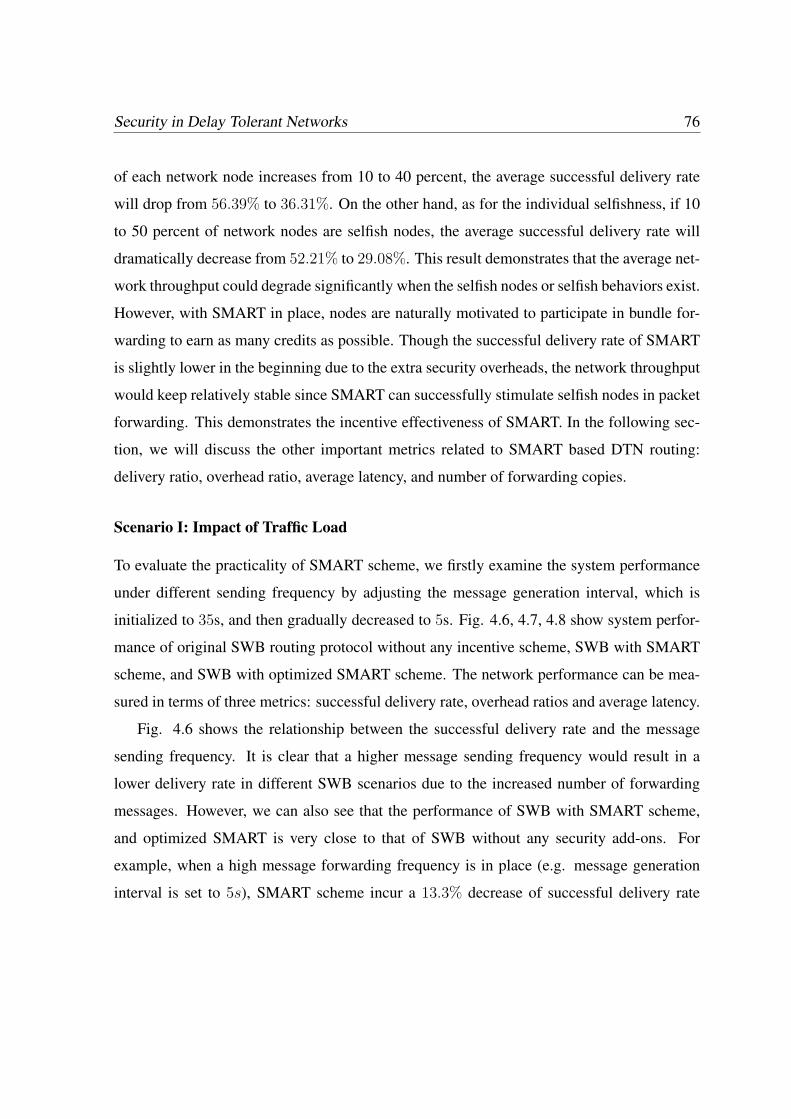
Security in Delay Tolerant Networks 76
of each network node increases from 10 to 40 percent, the average successful delivery rate
will drop from 56.39% to 36.31%. On the other hand, as for the individual selfishness, if 10
to 50 percent of network nodes are selfish nodes, the average successful delivery rate will
dramatically decrease from 52.21% to 29.08%. This result demonstrates that the average net-
work throughput could degrade significantly when the selfish nodes or selfish behaviors exist.
However, with SMART in place, nodes are naturally motivated to participate in bundle for-
warding to earn as many credits as possible. Though the successful delivery rate of SMART
is slightly lower in the beginning due to the extra security overheads, the network throughput
would keep relatively stable since SMART can successfully stimulate selfish nodes in packet
forwarding. This demonstrates the incentive effectiveness of SMART. In the following sec-
tion, we will discuss the other important metrics related to SMART based DTN routing:
delivery ratio, overhead ratio, average latency, and number of forwarding copies.
Scenario I: Impact of Traffic Load
To evaluate the practicality of SMART scheme, we firstly examine the system performance
under different sending frequency by adjusting the message generation interval, which is
initialized to 35s, and then gradually decreased to 5s. Fig. 4.6, 4.7, 4.8 show system perfor-
mance of original SWB routing protocol without any incentive scheme, SWB with SMART
scheme, and SWB with optimized SMART scheme. The network performance can be mea-
sured in terms of three metrics: successful delivery rate, overhead ratios and average latency.
Fig. 4.6 shows the relationship between the successful delivery rate and the message
sending frequency. It is clear that a higher message sending frequency would result in a
lower delivery rate in different SWB scenarios due to the increased number of forwarding
messages. However, we can also see that the performance of SWB with SMART scheme,
and optimized SMART is very close to that of SWB without any security add-ons. For
example, when a high message forwarding frequency is in place (e.g. message generation
interval is set to 5s), SMART scheme incur a 13.3% decrease of successful delivery rate

Chapter 4. A Secure Multi-Layer Credit-based Incentive Scheme for DTNs 77
5 10 15 20 25 30 350
0.1
0.2
0.3
0.4
0.5
0.6
0.7
0.8
0.9
1
The number of deployed nodes
Del
iver
y R
ate
Forwarding without securitywith basic SMARtwith optimized SMART
Figure 4.6: Impact of Network Load on System Performance: Successful Delivery Ratio

Security in Delay Tolerant Networks 78
while the optimized SMART scheme only incur a 8.3% decrease.
5 10 15 20 25 30 352000
2500
3000
3500
4000
4500
5000
Event generation speed
Ave
rage
Lat
ency
Forwarding without securitywith basic SMARTwith optimized SMART
Figure 4.7: Impact of Network Load on System Performance: Average Latency
Fig. 4.7 shows the average latency of different scenarios. It is observed that after a small
growth, the average latency will decrease quickly and optimized SMART has a comparable
performance with SMART scheme, both of which are less than the no-security system. This
is mainly caused by the dramatically decreased delivery rate.
Fig. 4.8 demonstrate that SMART and optimized SMART only have a slightly larger
overhead than no-incentive SWB. However, the increased overhead is not so significantly
and thus they have a similar overall performance.
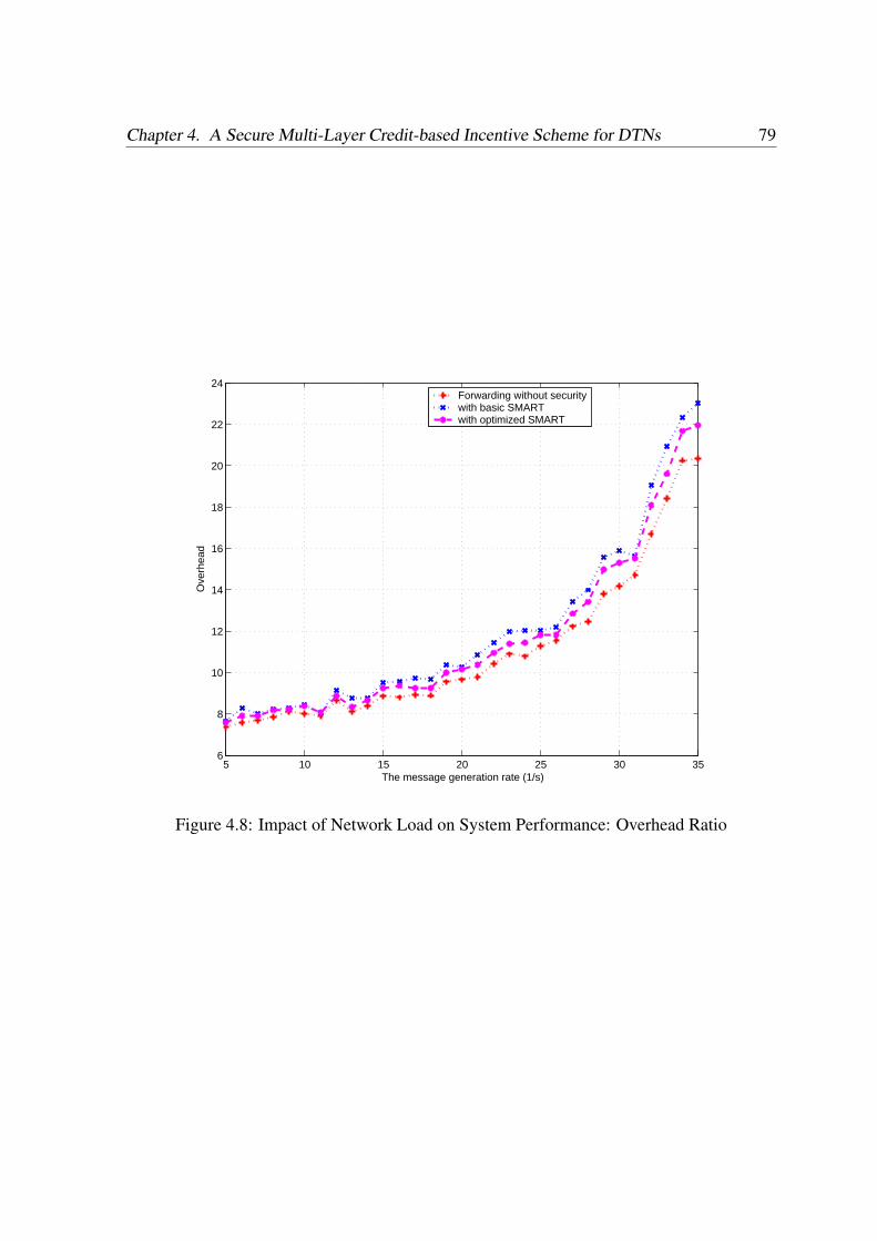
Chapter 4. A Secure Multi-Layer Credit-based Incentive Scheme for DTNs 79
5 10 15 20 25 30 356
8
10
12
14
16
18
20
22
24
The message generation rate (1/s)
Ove
rhea
d
Forwarding without securitywith basic SMARTwith optimized SMART
Figure 4.8: Impact of Network Load on System Performance: Overhead Ratio

Security in Delay Tolerant Networks 80
Scenario II: Impact of Forwarding Copy Number
Multi-copy data forwarding is a major characteristic of DTN data forwarding. In this section,
we investigate the impact of number of copies on the system performance and also study how
to find an optimal forwarding copy number with/out incentive mechanism.
5 10 15 20 25 300
0.1
0.2
0.3
0.4
0.5
0.6
0.7
0.8
0.9
1
The number of forwarding copy
Del
iver
y R
ate
Forwarding without securitywith basic SMARTwith optimized SMART
Figure 4.9: Impact of Forwarding Copy Number on System Performance: Delivery Ratio
In Fig. 4.9, 4.10 and 4.11, the number of forwarding copies is initially set to 1 and then
increased one by one. It is obvious that the delivery rate will grow very fast in the beginning
and then decrease after a specific threshold (for example, 5 in Fig. 4.9). This shows that an
optimal copy number exists to achieve a highest successful delivery rate.
On the other hand, from Fig. 4.10 and Fig. 4.11, it is observed that the average latency
will decrease with the increased copies while overhead will increase significantly along the
forwarding copies. By jointly considering the system performance and ensuring a certain
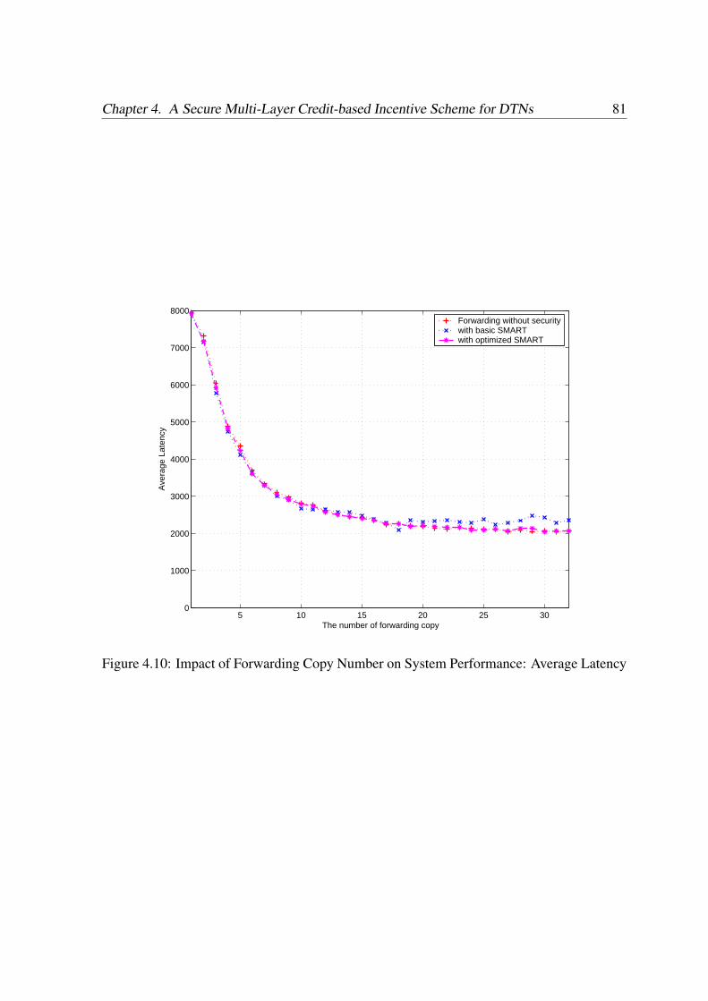
Chapter 4. A Secure Multi-Layer Credit-based Incentive Scheme for DTNs 81
5 10 15 20 25 300
1000
2000
3000
4000
5000
6000
7000
8000
The number of forwarding copy
Ave
rage
Lat
ency
Forwarding without securitywith basic SMARTwith optimized SMART
Figure 4.10: Impact of Forwarding Copy Number on System Performance: Average Latency
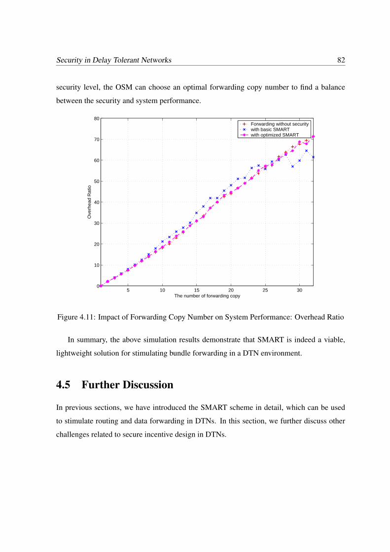
Security in Delay Tolerant Networks 82
security level, the OSM can choose an optimal forwarding copy number to find a balance
between the security and system performance.
5 10 15 20 25 300
10
20
30
40
50
60
70
80
The number of forwarding copy
Ove
rhea
d R
atio
Forwarding without securitywith basic SMARTwith optimized SMART
Figure 4.11: Impact of Forwarding Copy Number on System Performance: Overhead Ratio
In summary, the above simulation results demonstrate that SMART is indeed a viable,
lightweight solution for stimulating bundle forwarding in a DTN environment.
4.5 Further Discussion
In previous sections, we have introduced the SMART scheme in detail, which can be used
to stimulate routing and data forwarding in DTNs. In this section, we further discuss other
challenges related to secure incentive design in DTNs.
Chapter 4. A Secure Multi-Layer Credit-based Incentive Scheme for DTNs 83
4.5.1 Public Key Revocation in DTNs
Public key management is the foundation of any security protocols. In a secure incentive
scheme, any misbehaving or malicious nodes will pay the penalty of having their public key
certificates revoked. Even for those selfish nodes which run out of their credits, one possible
punishment action is also revoking their certificates or reducing their CoS right by revising
their certificates. However, public key revocation still represents a great challenge in de-
lay tolerant networks. In a traditional Public Key Infrastructure (PKI), the most commonly
adopted certificate revocation scheme is through a Certificate Revocation List (CRL), which
is a list of revoked certificates stored in central repositories prepared by the Certificate Au-
thorities (CAs). However, in DTNs, the nodes may suffer from delayed or frequent loss of
connectivity to CRL servers [57]. In [58], the use of periodical public key updating is sug-
gested to replace the traditional public key revocation, though, in the real world, public key
distribution is also a challenging problem and may lead to a lot of extra management costs.
Another possible way to address public key revocation in DTNs is by using cooperative CRL
distribution [57], which needs further investigation to find an improved method.
4.5.2 Public Key Cryptography vs Identity-based Cryptography
Currently, we use traditional public key certificate-based cryptography as the basic crypto-
graphic tool to realize our SMART scheme. One possible way to further improve the effi-
ciency of SMART is using Identity-Based Cryptography (IBC) to redesign the current public-
key-certificate-based protocol. Identity-based cryptography is a relatively new cryptographic
method and also a powerful alternative to traditional certificate-based cryptography [34]. Its
main idea is to make an entity’s public key directly derivable from its publicly known identity
information such as e-mail address. Recently, there have been several research proposals that
have suggested adoption of IBC to realize the efficient bundle authentication in DTNs [24].
However, it is straightforward to transform our public key certificate based SMART scheme
into an ID-based one by adopting a ID-based signature scheme such as [36]. Therefore,
Security in Delay Tolerant Networks 84
whether adopting IBC will not reduce the contribution of this work.
4.6 Summary
In this chapter, we have proposed a secure multi-layer credit based incentive (SMART)
scheme to stimulate cooperation in packet forwarding for delay tolerant networks. We have
also proposed two efficiency optimization methods to reduce the transmission and computa-
tion overhead. The SMART is compatible to diverse existing routing schemes and is expected
to improve the system performance of DTNs which suffer from selfishness. We also demon-
strated the efficiency and effectiveness of SMART through extensive simulations under dif-
ferent system parameters. Our future work includes a reputation based incentive scheme or
a secure incentive compatible routing scheme for DTNs.
Chapter 5
Practical Public Key Management in
DTNs with Cooperative CRL Caching
Public key management is the foundation of any public key certificate based security pro-
tocols. The current DTN security protocols including the one defined in Bundle Security
Specification are also based on the assumption that a well-defined public key infrastructure
exists to support these security operations. However, the unique security characteristics of
DTNs, such as long round-trip delay, lack of end-to-end connections and limited storage
space, make the existing public key management solutions for traditional wireline networks
or even ad hoc networks unsuitable for DTNs. Even in Bundle Security Specification [26], it
is explicitly pointed out that public key management in DTNs is still an open problem. This
motives us to discuss the public key management issue including the certification distribution
and revocation issue. In this chapter, we will review the public key certificate basics, then
we will discuss the difficulty of applying existing public key management solutions and then
focus on two public key management issues in DTNs, including certificate distribution and
CRL caching issues.
85

Security in Delay Tolerant Networks 86
5.1 Preliminaries
5.1.1 Public Key Certificate Basics
A public key certificate (or simply certificate) is the most basic element of a public key in-
frastructure (PKI), which was first created [59] for securely distributing public keys. Each
certificate contains a public key and identities the user with the corresponding private key.
The complete PKI system consists of a number of service components that handles certifi-
cates. For convenience of discussion, we only consider the two primary components of PKI.
• Certificates
• Certificate status information services
We discuss each of the components in the following sections.
Certificates
A public key certificate is a data structure that contains the public key and further information
associated with it. Typically, a certificate serves as a binding between the public key and
the principal, which identifies the user with the corresponding private key. A principal can
be human, server, client machine, software, privilege, or anything involved in public key
based communication. The entire contents of the certificate are digitally signed by the issuer.
The issuer creates and signs the certificate. The issuer may be a trusted authority, such as
Certification Authority (CA) or Attribute Authority (AA). Semi-trusted entities or untrusted
entities may also be issuers of certificates. As discussed by Housley and Polk [60], a public
key certificate is an approximation of the concept of ideal certificates. They define an ideal
certificate with the following nine features:
1. It is a pure digital object that allows distribution and processing automatically.
Chapter 5. Practical Public Key Management in DTNs with Cooperative CRL Caching 87
2. It contains the identity of the user who holds the private key. The identity refers to the
name, the organization, and contact information of the user.
3. It is easy to verify the freshness of the certificate. In other words, the certificate is
time-stamped by an issuance date, and it should be easy to compare the current time
with the issuance date.
4. The issuer of the certificate would be a trusted party.
5. The certificate should be uniquely and easily distinguished among a large number of
certificates.
6. It should be easy to protect the certificate from forgery. In other words, we can easily
determine the forged certificates.
7. After the certificate is created, it should stay untampered. Any unauthorized change on
the certificate should be easily identified.
8. The certificate should have an expiry date. Once current time has passed the expiry
date, we can determine that the information in the certificate is no longer current.
In addition to these features, we also need to establish additional services (Certificate
Status Information Services) to handle certificates, which will be discussed in the following
section.
Certificate Status Information (CSI) Services
Usually, every certificate has an expiration date that varies between few minutes to few years.
On some occasions, it is necessary to revoke an unexpired certificate. If a principal’s private-
key is exposed, the principal is no longer under the administration domain of a given CA, or
some of the certificate properties associated to that principal need to be changed are some
examples that necessitates existence of a revocation mechanism.
Security in Delay Tolerant Networks 88
CRL is a signed list of revoked unexpired certificates [61]. This list is distributed periodi-
cally to interested principals. CRL is a negative statement about the validity of the certificates
it contains and, hence, any certificate that is not in the CRL is considered valid (a double neg-
ative).The following list briefly illustrates the most common CRL distribution and certificates
validation mechanisms:
1. Basic CRL: CA issues a list containing the serial numbers of revoked but unexpired
certificates which contains the next issuance date. All revoked unexpired certificates
will be listed again when the time of the next issuance occurs. This list must be issued
periodically, even if no certificates have been revoked since the last CRL. Each CRL
must be properly signed and dated. If the CRL Distribution Point (CDP) extension
in X.509 certificate is populated [28], users get to know where and how to obtain the
CRLs needed to determine if the certificate is revoked.
2. Delta CRL: This was introduced to reduce the bandwidth and redundancy associated
with sending a complete list every time an update occurs. Instead, a delta CRL contains
the changes from the last baseline CRL. Therefore, it is usually short and often contains
no certificates [62].
3. First Valid Certificate: The scheme goal, again, is to make the CRL as small as possible
and to allow certificates not to have a predetermined expiration time when issued.
When the size of the CRL becomes too large, the CA will issue a notice requesting any
principal which holds a certificate with a serial number less than n to reissue a new
certificate within some time from the data of that notice. The number n is chosen in a
manner that only few serial numbers in the current CRL are greater than n. Revoked
certificates with serial numbers greater than n must continue to appear in the new
CRL [61].
4. Certificate Revocation Tree (CRT): Another CRL variant is Certificate Revocation Tree
(CRT), which reduce the transmission size incurred by CRL transmission [63]. In
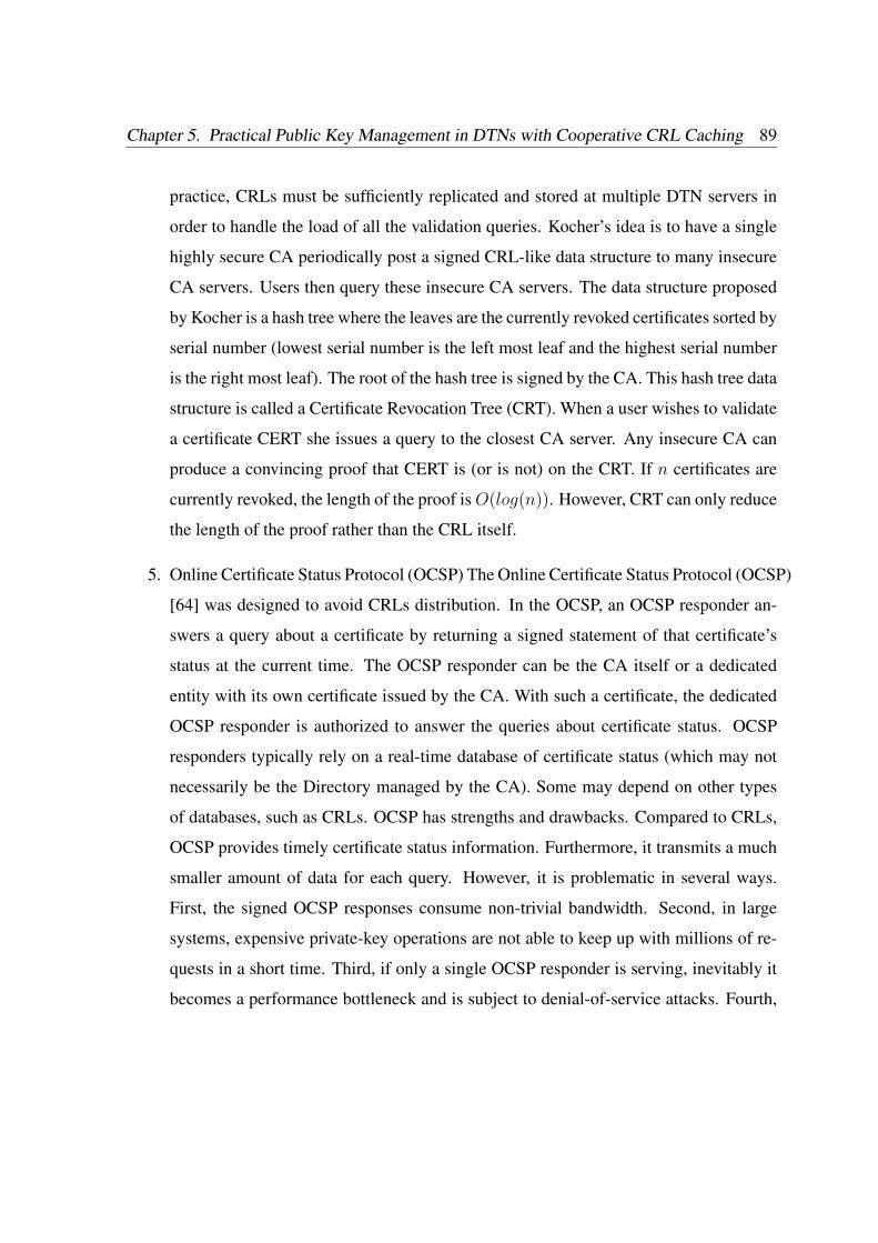
Chapter 5. Practical Public Key Management in DTNs with Cooperative CRL Caching 89
practice, CRLs must be sufficiently replicated and stored at multiple DTN servers in
order to handle the load of all the validation queries. Kocher’s idea is to have a single
highly secure CA periodically post a signed CRL-like data structure to many insecure
CA servers. Users then query these insecure CA servers. The data structure proposed
by Kocher is a hash tree where the leaves are the currently revoked certificates sorted by
serial number (lowest serial number is the left most leaf and the highest serial number
is the right most leaf). The root of the hash tree is signed by the CA. This hash tree data
structure is called a Certificate Revocation Tree (CRT). When a user wishes to validate
a certificate CERT she issues a query to the closest CA server. Any insecure CA can
produce a convincing proof that CERT is (or is not) on the CRT. If n certificates are
currently revoked, the length of the proof is O(log(n)). However, CRT can only reduce
the length of the proof rather than the CRL itself.
5. Online Certificate Status Protocol (OCSP) The Online Certificate Status Protocol (OCSP)
[64] was designed to avoid CRLs distribution. In the OCSP, an OCSP responder an-
swers a query about a certificate by returning a signed statement of that certificate’s
status at the current time. The OCSP responder can be the CA itself or a dedicated
entity with its own certificate issued by the CA. With such a certificate, the dedicated
OCSP responder is authorized to answer the queries about certificate status. OCSP
responders typically rely on a real-time database of certificate status (which may not
necessarily be the Directory managed by the CA). Some may depend on other types
of databases, such as CRLs. OCSP has strengths and drawbacks. Compared to CRLs,
OCSP provides timely certificate status information. Furthermore, it transmits a much
smaller amount of data for each query. However, it is problematic in several ways.
First, the signed OCSP responses consume non-trivial bandwidth. Second, in large
systems, expensive private-key operations are not able to keep up with millions of re-
quests in a short time. Third, if only a single OCSP responder is serving, inevitably it
becomes a performance bottleneck and is subject to denial-of-service attacks. Fourth,

Security in Delay Tolerant Networks 90
for services availability, OCSP responders have to remain online all the time, which
makes them attractive to attackers. Lastly, if distributed OCSP responders are provid-
ing the service to solve the performance bottleneck problem, we then face the infor-
mation synchronization problem. Furthermore, since these OCSP the adversary may
compromise any of the responders to compromise the entire system [65] .
Even though researchers have proposed various public key management as well as CRL dis-
tribution methods to realize efficient public key management in traditional networks, the ex-
isting methods do not work well in DTNs due to their unique characteristics. In the following
sections, we will discuss the public key management issue in DTNs.
5.1.2 Challenges of Public Key Management in DTNs
There are two major challenges for applying existing public key management methods in
DTNs: distribution challenges and storage challenges.
• Distribution Challenge: Due to the long round-trip delay, lack of end-to-end connec-
tions of DTN characteristic, OCSP does not work in DTNs since any OCSP request
will incur long signaling cost or even failure of response.
• Storage Challenge: CRL distribution may be a practical solution for DTN public
key revocation. A major problem is that, even though there are various proposals for
efficient CRL dissemination, they still face the challenge of limited storage capability
of DTN nodes.
In bundle security specification [26], it is suggest to use periodical key updating (e.g. short-
time certificate) to avoid the key revocation. However, there are still two challenges in terms
of periodic key updating.
• Technical Aspect: Periodic key updating cannot fully avoid key revocation issue. This
is because even between two key updating time, it is still possible for adversaries to
Chapter 5. Practical Public Key Management in DTNs with Cooperative CRL Caching 91
compromise the secret keys of key holders. Therefore, we still need to face the key
revocation issue during two updating intervals.
• Economical Aspect: Since certificate issuing itself is a lot of work, periodic key updat-
ing will inevitably increase workload on authorities dramatically. Further, for certain
users which fail to update the key in time, key updating increases their possibilities of
losing their normal network functionality. This may potentially decrease their satisfac-
tory on network services.
In this chapter, based on opportunistic CRL distribution and cooperative CRL caching,
we propose a practical public key management scheme for DTNs.
5.1.3 Bloom Filter
A Bloom filter is a simple space-efficient randomized data structure for representing a set
in order to support membership queries [66]. A Bloom filter for representing a set S =
s1, s2, . . . , sn of n elements is described by an array of m bits, initially all set to 0. A
Bloom filter uses k independent hash functions h1, . . . , hk with range 0, . . . , m − 1. We
make the natural assumption that these hash functions map each item in the universe to a
random number uniform over the range 0, . . . , m − 1 for mathematical convenience. For
each element s ∈ S, the bits hi(s) are set to 1 for 1 ≤ i ≤ k. A location can be set to 1
multiple times, but only the first change has an effect. To check if an item x is in S, we check
whether all hi(x) are set to 1. If not, then clearly x is not a member of S. If all hi(x) are set
to 1, we assume that x is in S, although we are wrong with some probability. Hence a Bloom
filter may yield a false positive, where it suggests that an element x is in S even though it is
not. For many applications, this is acceptable as long as the probability of a false positive is
sufficiently small.

Security in Delay Tolerant Networks 92
5.2 A Basic CRL Distribution Scheme in DTNs
5.2.1 Network Model
We consider a general delay tolerant network formed by a set of mobile devices owned by
individual users. Each node i is assumed to have a unique non-zero identifier Ni, which is
bound to a specific public key certificate. We use node i orNi interchangeably hereafter. We
also assume that each node has limited transmission and reception capabilities so that two
nodes outside the transmission range of each other can communicate only via a sequence of
intermediate nodes in a multi-hop manner. End-to-end connections are not always guaran-
teed, and routing, therefore, is made in an “opportunistic” way. We also assume that several
certificate revocation authorities (CRA) exist in the network in responsible for CRL distri-
bution. In many DTN application scenarios, there exist some special network components
which can serve as the CRA, such as roadside unit (RSU) in vehicular DTNs [50] and infor-
mation publisher in social networks [52]. Before joining the DTN network, every DTN node
should be registered with the OSM and obtain its public key certificate.
5.2.2 The Proposed Scheme
We briefly introduce the basic CRL distribution scheme as follows: A CRL updating pro-
cess could be initialized by the CRA, which broadcasts the updated CRLs to the one-hop
neighbors. Each receiving DTN node, in turn, transmits updated CRL to every node it en-
counters. This CRL propagation process is performed in an opportunistic way and similar to
the epidemic routing, where each “infected” node carries the updated CRL until it meets and
forwards the updated CRL to the next uninfected node. Peer-to-peer CRL propagation can be
regarded as a natural extension of traditional CRL distribution scheme [67, 68]. However, if a
large number of CRL distribution happens, which is broadcasted through the whole network,
it can even cause network congestion or hamper the provision of other high-priority services.
In the following section, we will take advantage of bloom filters to reduce the transmission
Chapter 5. Practical Public Key Management in DTNs with Cooperative CRL Caching 93
and storage overhead.
Bloom filter based CRL Generation and Propagation
Given the revoked public key certificate set S = N1, PKN1 , N2, PKN2 . . . , Nn, PKNn,
the CRA broadcasts the CRLs within the whole network. For each receiving DTN node, it
can apply k system-wide hash functions to map the elements of S (each with L + 2 bytes,
that is, |Ni| = 2 bytes, and PKNi= L bytes) to an m-bit vector V with V = v0v1 . . . vm−1,
where we have m < N(L+2) to reduce the filter size. These k hash functions are known by
every DTN node. For each vi, i ∈ [0,m− 1], we have
vi =
1, if ∃l ∈ [1, k], j ∈ [1, N ], s.t. hl(Ni||PKNi) = i
0, otherwise
For each CRL updating phase, CRA broadcasts V to one hop neighbors. V will be further
propagated within the network and the receiving node will cache it for future utilization.
Public Key Validation and CRL Checking
Whenever each intermediate node receives a bundle, it will validate the sender’s public key
certificate at first. After that, it checks the CSI information of the corresponding public key
by verifying its membership in S. To do so, the node checks whether V [hl(N1||PKN1)] =
1, l ∈ [1, k], and a negative result will lead to the discarding of the message. Using the Bloom
filter, instead of a list of MACs, greatly reduces the packet size. As one example, assume
that each MAC of a public key certificate is b = 64 bits, n= 8 key indices and 10 MACs are
required for caching. They take 64 ∗ 8 bits (about 80 bytes). Using a Bloom filter of k =
5 hash functions, which maps 5 MACs to an m = 64 bit string, the total required space is
reduced to 12.5% (only 8 bytes).
However, Bloom filter may yield false positives, i.e., an element is not in S but its bits
hi(s) are collectively marked by elements in S. If the hash is uniformly random over the m
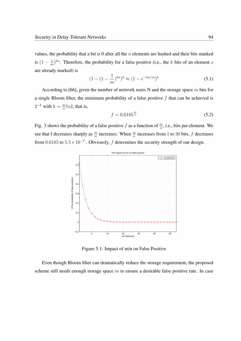
Security in Delay Tolerant Networks 94
values, the probability that a bit is 0 after all the n elements are hashed and their bits marked
is (1 − 1m
)kn. Therefore, the probability for a false positive (i.e., the k bits of an element s
are already marked) is
(1− (1− 1
m)kn)k ≈ (1− e−kn/m)k (5.1)
According to [66], given the number of network users N and the storage space m bits for
a single Bloom filter, the minimum probability of a false positive f that can be achieved is
2−k with k = mnln2, that is,
f = 0.6185mn (5.2)
Fig. 3 shows the probability of a false positive f as a function of mn
, i.e., bits per element. We
see that f decreases sharply as mn
increases. When mn
increases from 1 to 30 bits, f decreases
from 0.6185 to 5.5 ∗ 10−7 . Obviously, f determines the security strength of our design.
5 10 15 20 25 30−0.1
0
0.1
0.2
0.3
0.4
0.5
0.6
m/n (bit/user)
f (T
he p
roba
bilit
y of
fals
e po
sitv
e)
The impact of m/n on false positve
k=m/n In2
Figure 5.1: Impact of m/n on False Positive
Even though Bloom filter can dramatically reduce the storage requirement, the proposed
scheme still needs enough storage space m to ensure a desirable false positive rate. In case
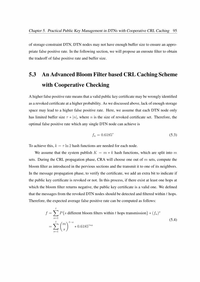
Chapter 5. Practical Public Key Management in DTNs with Cooperative CRL Caching 95
of storage-constraint DTN, DTN nodes may not have enough buffer size to ensure an appro-
priate false positive rate. In the following section, we will propose an enroute filter to obtain
the tradeoff of false positive rate and buffer size.
5.3 An Advanced Bloom Filter based CRL Caching Scheme
with Cooperative Checking
A higher false positive rate means that a valid public key certificate may be wrongly identified
as a revoked certificate at a higher probability. As we discussed above, lack of enough storage
space may lead to a higher false positive rate. Here, we assume that each DTN node only
has limited buffer size τ ∗ |n|, where n is the size of revoked certificate set. Therefore, the
optimal false positive rate which any single DTN node can achieve is
fn = 0.6185τ (5.3)
To achieve this, k = τ ln 2 hash functions are needed for each node.
We assume that the system publish K = m ∗ k hash functions, which are split into m
sets. During the CRL propagation phase, CRA will choose one out of m sets, compute the
bloom filter as introduced in the pervious sections and the transmit it to one of its neighbors.
In the message propagation phase, to verify the certificate, we add an extra bit to indicate if
the public key certificate is revoked or not. In this process, if there exist at least one hops at
which the bloom filter returns negative, the public key certificate is a valid one. We defined
that the messages from the revoked DTN nodes should be detected and filtered within t hops.
Therefore, the expected average false positive rate can be computed as follows:
f =t∑
s=1
Ps different bloom filters within t hops transmission ∗ (fn)s
=t∑
s=1
(m
s
)t−s
∗ 0.6185τ∗s(5.4)
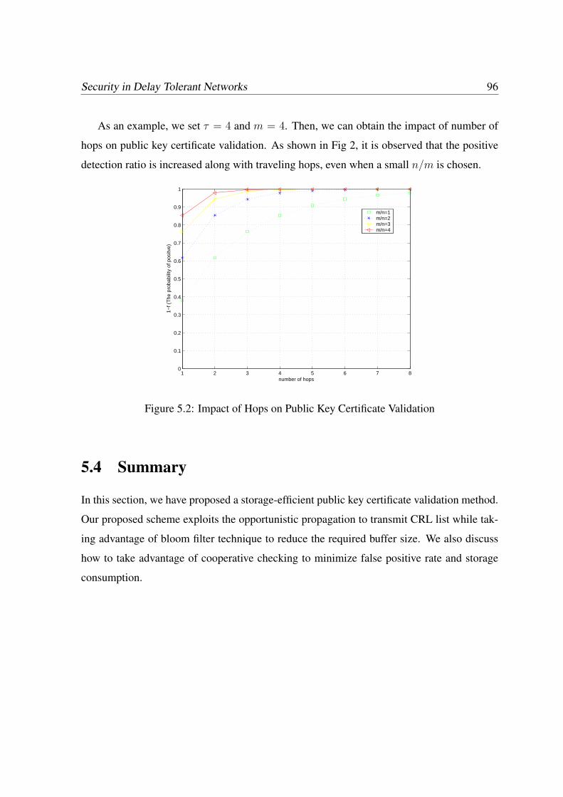
Security in Delay Tolerant Networks 96
As an example, we set τ = 4 and m = 4. Then, we can obtain the impact of number of
hops on public key certificate validation. As shown in Fig 2, it is observed that the positive
detection ratio is increased along with traveling hops, even when a small n/m is chosen.
1 2 3 4 5 6 7 80
0.1
0.2
0.3
0.4
0.5
0.6
0.7
0.8
0.9
1
number of hops
1−f (
The
pro
babi
lity
of p
ositv
e)
m/n=1m/n=2m/n=3m/n=4
Figure 5.2: Impact of Hops on Public Key Certificate Validation
5.4 Summary
In this section, we have proposed a storage-efficient public key certificate validation method.
Our proposed scheme exploits the opportunistic propagation to transmit CRL list while tak-
ing advantage of bloom filter technique to reduce the required buffer size. We also discuss
how to take advantage of cooperative checking to minimize false positive rate and storage
consumption.
Chapter 6
Conclusions and Future Work
In this chapter, the contributions of this thesis are concluded, followed by the future work.
6.1 Contributions
The major contributions of this thesis can be summarized as follows:
• We studied a series of DTN security characteristics which distinguish DTN security
from the security issues in conventional ad hoc networks and point out there research
challenges related to DTN security: efficient bundle authentication, selfish issue and
certificate revocation issue.
• To achieve efficient bundle authentication, we proposed an efficient batch bundle au-
thentication scheme to achieve efficient bundle authentication, which can be regarded
a complimentary of current bundle security specification.
• To address the selfish issue, we proposed an efficient credit based incentive scheme to
stimulate selfish nodes to forward data in DTNs.
• To achieve storage-efficient certificate revocation, we propose a practical DTN public
key management scheme to realize efficient certificate distribution and revocation.
97
Security in Delay Tolerant Networks 98
6.2 Future Work
Our research has made significant progress in securing DTNs. Yet this is still a very wide-
open field. There are several research directions to be explored to complement our efforts.
6.2.1 Privacy Preserving Protocols
Privacy functionality is an important aspect of DTN security. In particular, the user concerns
are not only about the disclosure of communication content to the public, but also about the
commercial misuse of their personal data. For example, location privacy is among the most
critical personal information and thus users may prefer to travel incognito [69]. To fulfill user
privacy preservation, the DTN operators have to adopt appropriate administrative, technical,
and physical security measures to protect users’ location privacy [70].
Privacy preserving is still a new research topic in DTNs and has received little attention.
Some existing privacy preserving technology such as mixnet or pseudonym can be employed
to enhance the anonymity of the DTN nodes. However, considering the unique characteristics
of DTNs, the existing privacy preserving schemes may not be suitable for DTNs and thus
privacy preserving issue should be more carefully examined.
6.2.2 Reputation based Incentive Scheme
Reputation-based scheme in DTNs is a challenging issue. Different from credit based in-
centive scheme, reputation-based schemes rely on the cooperation of neighboring nodes to
establish the nodes’ reputation, which can be utilized to achieve secure routing and/or enforc-
ing punishment [46]. However, applying reputation based incentive schemes in DTNs may
face the difficulty of monitoring the traffic since in DTNs, due to the unique “store-carry-
and-forward” transmission method, it is very difficult for a bundle forwarder to detect if a
subsequent forwarder indeed helps it to forward the bundle since the forwarder may “carry”
the packets and forward them when he is out of the sender’s transmission range. Further, fair-
Chapter 6. Conclusions and Future Work 99
ness issue is another major challenge for incentive scheme in DTNs since a fairness-aware
incentive scheme should ensure that the data forwarding should be performed in a fair way.
In other words, each forwarding node should be rewarded with increased reputation while
each selfish node should be penalized with decreased reputation. After all, reputation-based
incentive scheme is an important part of DTN routing. Therefore, the reputation-based in-
centive scheme deserves our further investigation.
In conclusion, due to these unresolved research challenges, we will keep on working on
them in our future research. We will also consider other latest research progresses such as
network coding and study the security issue related to them.
Bibliography
[1] P. Juang, H. Oki, Y. Wang, M. Martonosi, L.-S. Peh, and D. Rubenstein, “Energy-
efficient computing for wildlife tracking: Design tradeoffs and early experiences with
zebranet,” In Proc. of ACM ASPLOS, 2002.
[2] T. Small, and Z. J. Haas, “The Shared Wireless Infostation Model - a new ad hoc net-
working paradigm,” In Proc. of ACM MOBIHOC’03, 2003.
[3] J. Partan, J. Kurose, and B. N. Levine, “A Survey of Practical Issues in Un- derwa-
ter Networks, ” In Proc. of ACM International Workshop on UnderWater Networks
(WUWNet’06), 2006.
[4] J. -H. Cui, J. Kong, M. Gerla, and S. Zhou, “Challenges: Building scalable mobile
underwater wireless sensor networks for aquatic applications,” IEEE Network, May
2006.
[5] R. Lu, X. Lin, H. Zhu, P.H. Ho and X. Shen, “ECPP: Efficient conditional pri-
vacy preservation protocol for secure vehicular communications,”In Proc. IEEE IN-
FOCOM’08, Phoenix, USA, April, 2008.
[6] P. Hui, J. Crowcroft and E. Yoneki, “BUBBLE Rap: Social-based forwarding in delay
tolerant networks,” In Proc. MobiHoc’08, Hongkong, China, May, 2008.
100
Bibliography 101
[7] A. Chaintreau, P. Hui, J. Crowcroft, C. Diot, R. Gass, and J. Scott, “Impact of Human
Mobility on the Design of Opportunistic Forwarding Algorithms,” In Proc. of IEEE
Infocom’06, 2006.
[8] Communications for High-Speed Moving Objects: IEEE 802.16e, IEEE 802.20 and 5.9
GHz DSRC. http://www.researchandmarkets.com/reports/c50922.
[9] S. Ahmed and S. S. Kanhere, “Cluster-based forwarding in delay tolerant public trans-
port networks,” In Proc. of IEEE Conference on Local Computer Networks, 2007.
[10] H. Jun, M. Ammar, M. Corner, and E. Zegura, “Hierarchical Power Management in
Disruption Tolerant Networks with Traffic-Aware Optimization,” In Proc. of ACM SIG-
COMM Workshop on Challenged Networks (CHANTS’06), 2006.
[11] A. Krifa, C. Barakat, and T. Spyropoulos, “Optimal buffer management policies for
delay tolerant networks,” In Proc. of SECON’08, 2008.
[12] W. Zhao, Y. Chen, M. Ammar, M. D. Corner, B. N. Levine, and E. Zegura, “Capacity
Enhancement using Throwboxes in DTNs,” In Proc. of IEEE MASS’06, 2006.
[13] W. Zhao, M. Ammar, and E. Zegura, “A Message Ferrying Approach for Data Delivery
in Sparse Mobile Ad Hoc Networks,” In Proc. of ACM MOBIHOC’06, 2006.
[14] S. Jain, K. Fall, and R. Patra, “Routing in a Delay Tolerant Network,” In Proc. of ACM
SIGCOMM’04, 2004.
[15] T. Spyropoulos, K. Psounis and C. S. Raghavendra, “Efficient routing in intermittently
connected mobile networks: the multiple-copy cast,” IEEE/ACM Trans. on Networking,
vol. 16, no. 1, Feb. 2008.
[16] T. Spyropoulos, K. Psounis and C. S. Raghavendra, “Efficient routing in intermittently
connected mobile networks: the single-copy cast,” IEEE/ACM Trans. on Networking,
vol. 16, no. 1, Feb. 2008.

Bibliography 102
[17] S. Jain, K. Fall, and Rabin Patra, “Routing in a Delay Tolerant Network,” In Proc. of
the ACM SIGCOMM’04, 2004.
[18] A. Vahdat and D. Becker, “Epidemic routing for partially connected ad hoc networks,”
Technical Report CS-200006, Duke University, April 2000.
[19] A. Lindgren, A. Doria and O. Schelen, “Probabilistic Routing in Intermittently Con-
nected Networks,” In Proc. of SAPIR, 2004.
[20] Y. Wang, S. Jain, M. Martonosi, and K. Fall, “Erasure-coding based routing for oppor-
tunistic networks,” In Proc. of SIGCOMM WDTN’05 2005.
[21] J. Widmer, and J.-Y. Le. Boudec, “Network Coding for Efficient Communication in
Extreme Networks,” In Proc. of SIGCOMM WDTN’05, 2005.
[22] X. Zhang, G. Neglia, J. Kurose, and D. Towsley, “On the Benefits of Random Linear
Coding for Unicast Applications in Disruption Tolerant Networks,” In Proc. of NET-
COD’06, 2006.
[23] S. Farrell, S. Symington, H. Weiss, and P. Lovell, ”Delay- Tolerant Networking Security
Overview”, draft-irtf-dtnrg-sec-overview-04.txt, work-in-progress, February 2008.
[24] N. Asokan, K. Kostiainen, P. Ginzboorg, J. Ott and Cheng Luo, “Applicability of
identity-based cryptography for disruption-tolerant networking,” In Proc. of MobiOpp,
June 2007.
[25] A. Kate, G. Zaverucha and Urs Hengartner, “Anonymity and security in delay tolerant
networks,” In Proc. of SecureComm’07, Sept. 2007.
[26] S. Farrell, S. Symington, H. Weiss, and P. Lovell, “Bundle Security Protocol Specifica-
tion,” draft-irtf-dtnrg-sec-overview-04.txt, work-in-progress, February 2008.
Bibliography 103
[27] DTNRG. Delay tolerant networking research group: dtn-interest mailing list archive,
April 2005. Available from http:// mailman.dtnrg.org/pipermail/dtn-interest/2005-
April/.
[28] R. Housley, W. Polk, W. Ford, and D. Solo,“Internet X.509 Public Key Infrastructure
Certificate and Certificate Revocation List (CRL) Profile,” RFC 3280, April 2002.
[29] C. Liu and J. Wu, “Scalable routing in delay tolerant networks,” In Proc. of Mobi-
Hoc’07, Montreal, Canada, September 9-14, 2007.
[30] N. Asokan, K. Kostianinen, P. Ginzboorg, J. Ott, and C. Luo, “Towards securing
disruption-tolerant networking,” Nokia Research Center, Tech. Rep. NRC-TR-2007-
007.
[31] S. Farrell and V. Cahill, “Security consideartons in space and delay tolerant networks,”
In Proc. of SMC-IT’06, July 2006.
[32] S. Farrell and V. Cahill, “DTN: An architectural retrospective,” IEEE J. Sel. Areas Com-
mun., vol. 26, no. 5, pp. 828-836, June 2008.
[33] N. Asokan, K. Kostiainen, P. Ginzboorg, J. Ott and Cheng Luo, “Applicability
of identity-based cryptography for disruption-tolerant networking,” In Proc. of Mo-
biOpp’07, June 2007.
[34] D. Boneh and M. Franklin, “Identity based encryption from the Weil Pairing,” In Proc.
of Crypto’01, LNCS, vol. 2139, pp. 213-229, Springer-Verlag, 2001.
[35] A. L. Ferrara, M. Green, S. Huhenberger and M. Pedersen, “On the practicality of short
signature batch verification,” available in http://eprint.iacr.org/2008/015.pdf, 2008.
[36] J. C. Cha and J. H. Cheon, “An identity-based signature from gap Diffie-Hellman
groups,” In Proc. of PKC’03, vol. 2567, pp. 18-30. 2003.
Bibliography 104
[37] J. Pastuszak, D. Michatek, J. Pieprzyk, and J. Seberry, “Identification of bad signatures
in batches,” In Proc. of PKC’00, vol. 3958, pp. 28-45, Springer-Verlag, 2000.
[38] R. Merkle, “Protocols for public key cryptosystems,” In Proc. of IEEE S&P, pp. 122-
133, 1980.
[39] H. Chan and A. Perrig, “Efficient security primitives derived from a secure aggregation
algorithm,” In Proc. of CCS’08, Alexandria, Virginia, USA, October 27-31, 2008.
[40] The One Simulator: http://www.netlab.tkk.fi/tutkimus/dtn/theone/.
[41] Multiprecision Integer and Rational Arithmetic C/C++ Library (MIRACL).
[42] K. Ren, W. Lou and Y. Zhang, “Multi-user broadcast authentication in wireless sensor
networks,” In Proc. of SECON’07, 2007.
[43] Y. Zhang,W. Liu,W. Lou, and Y. Fang, “Location-based compromise-tolerant security
mechanisms for wireless sensor networks,” IEEE J. Sel. Areas Commun., vol. 24, no.2,
pp.247-260, 2006.
[44] M. Pitkanen, M. Keranen and J. Ott, “Message fragmentation in opportunistic DTNs,”
In Proc. of WoWMoM 2008, 2008.
[45] S. Marti, T. Giuli, K. Lai, and M. Baker, “Mitigating routing misbehavior in mobile ad
hoc networks,” In Proc. of ACM Mobicom, Boston, Massachusetts, August 2000.
[46] Q. He, D. Wu, and P. Khosla, “SORI: A Secure and Objective Reputation-Based In-
centive Scheme for Ad Hoc Networks,” In Proc. of WCNC 2004, Atlanta, GA, Mar.
2004.
[47] Y. Zhang and Y. Fang, “A fine-grained reputation system for reliable service selection
in peer-to-peer networks,” IEEE Trans. on Parallel and Distributed Systems, vol. 18,
no. 8, pp. 1134-1145, August 2007.
Bibliography 105
[48] S. Buchegger and J. Le Boudec, “Performance analysis of the CONFIDANT proto-
col: cooperation of nodes - fairness in distributed ad-hoc networks,” In Proc. of Mobi-
HOC’02, Lausanne, Switzerland, June 2002.
[49] Y. Zhang, W. Lou, W. Liu and Y. Fang, “A secure incentive protocol for mobile ad hoc
networks,” ACM Wireless Networks, vol. 13, no. 5, pp. 569-582, October 2007.
[50] S. B. Lee, G. Pan, J-S Park, M. Gerla and Songwu Lu, “Secure incentives for commer-
cial ad dissemination in vehicular networks,” In Proc. of MobiHoc’07, Sept. 2007.
[51] R. Lu, X. Lin, H. Zhu, C. Zhang, P.H. Ho and X. Shen, “A Novel Fair Incentive Protocol
for Mobile Ad Hoc Networks,” In Proc. IEEE WCNC’08, Las Vegas, Nevada, USA,
March 31 - April 3, 2008.
[52] A. Garyfalos and K. C. Almeroth, “Coupons: A Multilevel Incentive Scheme for Infor-
mation Dissemination in Mobile Networks,” IEEE Trans. on Mobile Computing, vol. 7,
no. 6, June 2008.
[53] M. Felegyhazi, J.-P. Hubaux, and L. Buttyan, “Nash Equilibria of Packet Forwarding
Strategies in Wireless Ad Hoc Networks,” IEEE Trans. on Mobile Computing, 2006.
[54] S. Zhong, J. Chen, and Y. Yang, “Sprite: A Simple, Cheat-proof, Credit-based System
for Mobile Ad-hoc Networks,” In Proc. of IEEE Infocom’03, 2003.
[55] S. Zhong, L. Li, Y. Liu and Y. Yang, “On Designing Incentive-compatible Routing and
Forwarding Protocols in Wireless Ad-hoc Networks” Wireless Networks, vol. 13, pp.
799-816, 2007.
[56] D. Boneh, B.Lynn and H. Shacham, “Short signatures from the weil pairing,” Journal
of Cryptology, vol. 17, no. 4, pp. 297-319, 2004.
[57] X. Lin, R. Lu, C. Zhang, H. Zhu, P.H. Ho, and X. Shen, “Security in Vehicular Ad Hoc
Networks,” IEEE Communications Magazine, Vol. 46, No. 4, 88-95, 2008.
Bibliography 106
[58] A. Seth, U. Hengartner, and S. Keshav, “Practical Security for Disconnected Nodes,” In
Proc. of NPSec’05, November, 2005.
[59] L. M. Kohnfelder, “Toward a Practical Public-Key Cryptosystem,” bachelor’s thesis,
Dept. Electrical Engineering, MIT, Cambridge, Mass., 1978.
[60] R. Housley and T. Polk, “Planning for PKI,” John Wiley Sons, Inc., 2001.
[61] C. Kaufman, R. Perlman, and M. Speciner, “Network security: Private Communication
in a public world,” Prentice Hall, 2nd edition, 2002.
[62] D. A. Cooper, “A More Efficient Use of Delta-CRLs,” In Proc. of IEEE Symposium on
S& P’ 2000, pages 190-202, May 2000.
[63] P. C. Kocher, “On Certifficate Revocation and Validation,” In Proc. of the Second Inter-
national Conference on Financial Cryptography (FC’98), volume 1465 of LNCS, pages
172-177. Springer-Verlag, 1998.
[64] M. Myers, R Ankney, A. Malpani, S. Galperin, and C. Adams, “X.509 Internet Pub-
lic Key Infrastructure Online Certificate Status Protocol,” RFC2560, http://www.ietf.
org/rfc/rfc2560.txt, June 1999.
[65] M. Zhao, “Performance Evaluation of Distributed Security Protocols Using Discrete
Event Simulation”, Phd’s thesis, Dept. Computer Science, Dartmouth College, 2005.
[66] M. Mitzenmacher, “Compressed Bloom Filters,” IEEE/ACM Transactions on Networks,
no. 10, vol.5, pp. 613-620, October 2002.
[67] K. P. Laberteaux, J. J. Haas, and Y.-C. Hu, “Security Certificate Revocation List Distri-
bution for VANET,” In Proc. of VANET 2008, San Francisco, CA, September 2008.
[68] P. Papadimitratos, G. Mezzour and J.-P. Hubaux, “Certificate Revocation List Distribu-
tion in Vehicular Communication Systems,” In Proc. of VANET 2008, San Francisco,
CA, September 2008.

Bibliography 107
[69] G. Ateniese, A. Herzberg, H. Krawczyk and G. Tsudik, “Untraceable mobility or how
to travel incognito,” Computer Networks, vol. 31, no. 8, pp. 871-884, Apr 1999.
[70] B. Schilit, J. Hong and M. Gruteser, “Wireless location privacy protection,” Computer,
vol. 36, no. 12, pp. 135-137, Dec. 2003.
Author’s Publications
Journal
[J1] H. Zhu, X. Lin, R. Lu, Y. Fan, and X. Shen, “SMART: A Secure Multi-Layer Credit based In-
centive Scheme for Delay-Tolerant Networks,” IEEE Trans. on Vehicular Technology (TVT),
to appear.
[J2] H. Zhu, X. Lin, M. Shi, P.H. Ho, and X. Shen, “PPAB: A Privacy Preserving Roaming and
Billing Architecture for Wireless Metropolitan Area Networks,” IEEE Trans. on Vehicular
Technology (TVT), to appear in 2009.
[J3] H. Zhu, X. Lin, R. Lu, P.H. Ho, and X. Shen, “SLAB: Secure Localized Authentication and
Billing Scheme for Wireless Mesh Networks,” IEEE Trans. on Wireless Communications
(TWC), vol. 17, no. 10, Oct. 2008.
[J4] H. Zhu, X. Lin, R. Lu, X. Shen, “Security in Service-Oriented Vehicular Networks,” IEEE
Wireless Communication Magazine, to appear.
[J5] Y. Jiang, H. Zhu, M. Shi, X. Shen and C. Lin, “Secure Network Coding via Efficient Packet
Filtering,” Computer Networks (COMNET), to appear.
[J6] X. Lin, R. Lu, C. Zhang, H. Zhu, P.H. Ho, and X. Shen, “Security in Vehicular Ad Hoc
Networks,” IEEE Communications Magazine, vol.46, no.4, pp.88-95, 2008.
[J7] R. Lu, X. Lin, H. Zhu, P.H. Ho, and X. Shen, “A Novel Anonymous Mutual Authentication
Protocol with Provable Link-Layer Location Privacy,” IEEE Trans. on Vehicular Technology
(TVT), vol. 58, no. 3, March. 2009.
108
Author’s Publications 109
[J8] X. Lin, X. Ling, H. Zhu, P.H. Ho, and X. Shen, “A Novel Localized Authentication Scheme
in IEEE 802.11 based Wireless Mesh Networks,” Int. J. of Security and Networks (IJSN), vol.
3, no. 2, pp. 122-132, 2008.
[J9] H. Zhu, X. Lin, R. Lu, X. Shen and T. Zhang, “Securing Vehicular Delay Tolerant Networks”,
submitted to IEEE Communication Magazine.
Conference
[C1] H. Zhu, R. Lu, X. Lin, X. Shen and Z. Cao, “OBBA: An Opportunistic Batch Bundle Authen-
tication Scheme for Delay Tolerant Networks,” in revision, 2009.
[C2] R. Lu, X. Lin, H. Zhu, and X. Shen, “BEA: Bandwidth-Efficient Authentication Schemes for
Filtering of Injected False Data in Wireless Sensor Networks”, in revision, 2009.
[C3] Y. Fan, Y. Jiang, H. Zhu and X. Shen, “An Efficient Privacy-Preserving Scheme against Traf-
fic Analysis Attacks in Network Coding,” Annual IEEE Conference on Computer Commu-
nications (IEEE INFOCOM’09), Rio de Janeiro, Brazil, April 19-25, 2009. (AcceptanceRatio=282/1435 < 20%)
[C4] R. Lu, X. Lin, H. Zhu and X. Shen, “SPARK: A New VANET-based Smart Parking Scheme
for Large Parking Lots,” Annual IEEE Conference on Computer Communications (IEEEINFOCOM’09), Rio de Janeiro, Brazil, April 19-25, 2009. (Acceptance Ratio=282/1435 <
20%)
[C5] H. Zhu, X. Lin, R. Lu and X. Shen, “A Secure Incentive Scheme for Delay Tolerant Networks”,
Proc. of International Conference on Communications and Networking in China (China-com’08), Hangzhou, China, Aug. 25-27, 2008. (Best Paper Award for Wireless
Communication Symposium)
[C6] H. Zhu, X. Lin, R. Lu, X. Shen and P.H. Ho, “BBA: An Efficient Batch Bundle Authentication
Scheme for Delay Tolerant Networks”, Proc. of IEEE Global Telecommunications Conference
(IEEE Globecom’08), New Orleans, LA, USA, Nov. 30 - Dec. 4, 2008.
[C7] H. Zhu, X. Lin, R. Lu, P.H. Ho, and X. Shen, “AEMA: An Aggregated Emergency Message
Authentication Scheme for Enhancing the Security of Vehicular Ad Hoc Networks,” Proc.
IEEE International Conference on Communications (IEEE ICC’08), Beijing, China, May 19-
23, 2008.
Author’s Publications 110
[C8] H. Zhu, X. Lin, R. Lu, P.H. Ho, and X. Shen, “Secure Localized Authentication and Billing
for Wireless Mesh Networks,” Proc. IEEE Global Telecommunications Conference (IEEEGlobecom’07), Washington DC, USA, November 26-30, 2007.
[C9] H. Zhu, X. Lin, P.H. Ho, X. Shen, and M. Shi, “TTP Based Privacy Preserving Inter-WISP
Roaming Architecture for Wireless Metropolitan Area Networks,” Proc. IEEE Wireless Com-
munications & Networking Conference (IEEE WCNC’07), Hong Kong, March 11-15, 2007.
[C10] R. Lu, X. Lin, H. Zhu, P.H. Ho and X. Shen, “ECPP: Efficient Conditional Privacy Preser-
vation Protocol for Secure Vehicular Communications,” Proc. Annual IEEE Conference on
Computer Communications (IEEE INFOCOM’08), Phoenix, AZ, USA, April 14-18, 2008.
(Acceptance Ratio=236/1152 = 20.5%)
[C11] X. Lin, R. Lu, H. Zhu, P.H. Ho, and X. Shen, “Provably Secure Self-certified Partially Blind
Signature Scheme from Bilinear Pairings,” Proc. IEEE International Conference on Commu-
nications (IEEE ICC’08), Beijing, China, May 19-23, 2008.
[C12] R. Lu, X. Lin, C. Zhang, H. Zhu, P.H. Ho, and X. Shen, “AICN: An Efficient Algorithm to
Identify Compromised Nodes in Wireless Sensor Network,” Proc. IEEE International Confer-
ence on Communications (IEEE ICC’08), Beijing, China, May 19-23, 2008.
[C13] R. Lu, X. Lin, H. Zhu, P.H. Ho, X. Shen, and Z. Cao, “A New Dynamic Group Key Manage-
ment Scheme with Low Rekeying Cost,” Proc. IEEE Wireless Communications & Networking
Conference (IEEE WCNC’08), Las Vegas, Nevada, USA, March 31 - April 3, 2008.
[C14] R. Lu, X. Lin, H. Zhu, C. Zhang, P.H. Ho and X. Shen, “A Novel Fair Incentive Protocol for
Mobile Ad Hoc Networks,” Proc. IEEE Wireless Communications & Networking Conference
(IEEE WCNC’08), Las Vegas, Nevada, USA, March 31 - April 3, 2008.
[C15] X. Lin, R. Lu , H. Zhu, P.H. Ho, X. Shen, and Z. Cao, “ASRPAKE: An Anonymous Se-
cure Routing Protocol with Authenticated Key Exchange for Wireless Ad Hoc Networks,”
Proc. IEEE International Conference on Communications (IEEE ICC’07), Glasgow, UK,
June 24-28, 2007. (Best Paper Award for Computer and Communications
Security Symposium)
Author’s Publications 111
[C16] X. Lin, H. Zhu, P.H. Ho, and X. Shen, “Two-factor Localized Authentication Scheme for
WLAN Roaming,” Proc. IEEE International Conference on Communications (IEEE ICC’07),Glasgow, UK, June 24-28, 2007.
[C17] X. Lin, H. Zhu, B. Lin, P.H. Ho, and X. Shen, “A Novel Voting Mechanism for Compromised
Node Revocation in Wireless Ad Hoc Networks,” Proc. IEEE Global Telecommunications
Conference (IEEE Globecom’06), San Francisco, USA, Nov. 27-Dec. 1, 2006.