Embed Size (px)
Citation preview

SECTIONTHREE Project Description and Location
W:\27658031\AFC Sections\Master TOC.doc\20-Nov-08\SDG 3-1
SECTION 3 PROJECT DESCRIPTION AND LOCATION
3.1 INTRODUCTION
The Project will consist of two hybrid design solar thermal electric generating plants (the Plants), each Plant comprised of a solar field, a biomass facility and ancillary facilities. The two Plants—SJS 1&2—will each produce up to a nominal 53.4 MW net of qualified renewable energy. The two Plants will be owned and operated by the Applicant. The electricity generated by the Plants will meet the requirements of two PPAs with PG&E. Each Plant will be sized for a nominal 53.4 MW net of solar generation, complemented by 40 MW net of biomass-generated production. The biomass energy production will be subordinate to production from the solar field, supplementing solar production during non-solar periods and shoulder solar hours. Thus, the maximum net generating capacity of the Plants will be 53.4 MW each.
3.2 LOCATION OF FACILITIES
The Project site is in Fresno County in the southern San Joaquin Valley, 6 miles east of the City of Coalinga. The proposed site (shown on Figure 3.2-1) is approximately 3 miles west of the intersection of Interstate 5 and West Jayne Avenue. Figures 3.2-2 and 3.2-3 depict the Project site and surrounding area. Roadway access to the site will be from West Jayne Avenue, which runs adjacent and parallel to the northern border of the entire site.
The legal description of the property and Fresno County APN are as follows:
• Legal Description: California, Mt. Diablo Meridian T21S, R16E, Section 3
• APNs 085-030-57S, 085-030-55S, and 085-030-58S
Transmission interconnection will be with the Gates Substation, located 6 miles east of the Project site.
3.3 SITE DESCRIPTION
The Project footprint will occupy the entire 640-acre area of Section 3, Township 21 South, Range 16 East. The Project site is presently zoned Exclusive Agricultural and is in active agricultural use, which includes plowing, growing, and cultivating a variety of crops. The site is generally flat and slopes down gently to the southwest with elevations ranging from approximately 570 feet to 620 feet above msl. Figure 3.3-1 presents the topography of the Project site. The surrounding area is devoted almost exclusively to agricultural farming and rangeland; however, recent developments include construction of the Pleasant Valley State Prison and the Coalinga State Hospital, both located on the section of land immediately west of the Project site.
Much of the Project site is currently protected agricultural land as described under the Williamson Act. A Williamson Act contract (Contract #3219) covers the 468.9-acre parcel (APN# 085-030-57S). The remaining 171.12 acres (comprising parcels APN# 085-030-55S and APN# 085-030-58S) are not under a Williamson Act contract. A discussion of the Williamson Act Contract cancellation process, which has already begun, is presented in Section 5.9, Land Use. Appendix A-1 Property Owners within 1,000 feet,

SECTIONTHREE Project Description and Location
3-2 W:\27658031\AFC Sections\Master TOC.doc\20-Nov-08\SDG
contains a list of current APNs and owners’ names and addresses for all parcels within 1,000 feet of the proposed Project and related facilities.
3.4 FACILITY DESCRIPTION
3.4.1 Site Arrangement
The proposed Project will consist of two Plants. Each Plant will have a dedicated solar field, biomass facilities, and power block. The northern third of the proposed Project site comprises the solar field for one Plant: SJS 1; similarly, the southern third of the proposed Project site comprises the solar field for SJS 2. In between the solar fields are the biomass facilities and power blocks for both SJS 1&2, in addition to shared facilities, including:
• Biomass storage and handling;
• Water facilities and evaporation ponds;
• Substation and transformers;
• Interconnection;
• Roads; and
• Control, maintenance and storage buildings.
A site plan of the Project is presented as Figure 3.4-1. Figures 3.4-2 and 3.4-3 provide an overview Project schematic and depict the relative locations of SJS 1&2 Plants. Typical elevation views are provided in Appendix A-2.
3.4.2 Solar Process Description
Each Plant will employ a conventional Rankin Cycle Steam Turbine Generator fueled by energy from two renewable sources: solar thermal and biomass. This section describes SJS 1&2 solar thermal components, followed by a description of the major solar field components.
Between sunrise and sunset, the solar fields will produce the majority of heat for steam production. A field of solar collector assemblies (SCAs) will collect the sun’s radiation and reflect and concentrate that radiation onto a series of heat collection elements (HCEs) containing a hot circulating oil—heat transfer fluid (HTF). The HCEs consist of a steel tube annulus encased in vacuum-sealed glass tube. Sunlight passes through the glass tube and insulating vacuum, is absorbed by the interior steel tube, and heats the HTF inside the steel tube. The HTF passes over a series of mirrors with a total length of about 2,000 feet, and exits the solar field at a temperature of about 740°F. The hot HTF is utilized to create superheated steam (725°F, 1,400-1,500 pounds per square inch [psi]), which is then sent to the steam turbine for electricity generation. The HTF is cooled as heat is transferred to produce steam and returns to the HCEs in the solar field at about 550°F. At any given time, the hot circulating oil in the solar field retains enough heat (or thermal inertia) to continue to operate the steam turbine cycle for 30 to 60 minutes, even if sunlight is interrupted, though production will progressively decline as the thermal inertia in the system is dissipated. Where practical (when periods of interruption of radiation are anticipated to extend for several

SECTIONTHREE Project Description and Location
W:\27658031\AFC Sections\Master TOC.doc\20-Nov-08\SDG 3-3
hours), the biomass system can be utilized to offset some of this decline, subject to the practical limitations of transitioning production from solar to biomass and back to solar. Figure 3.4-4 illustrates the process flow of one Plant and the tie-in between the solar and biomass facilities. Heat balance diagrams for the various operating modes are presented in Appendix A-3.
During daytime solar hours, each Plant will generate 53.4 MW of net electric power production from the solar fields. When solar radiation is less intense, solar generation can be supported with biomass generation up to the rated capacity of the steam turbine. During nighttime hours, biomass combustion will provide up to 40 MW net from each Plant without any solar input, and will maintain the solar field in a hot-standby condition such that quick transfer to solar production can be accomplished when solar radiation is again available.
3.4.2.1 History and Background of Technology
SJS 1&2 will employ the Solar Energy Generating Systems (SEGS) technology. SEGS was developed and demonstrated by Luz, Inc. with the first commercial operation of SEGS I in the mid-1980s and followed by the installation of SEGS II - IX over the next decade. At the core of SEGS technology is the use of parabolic trough solar thermal collectors, which operate on the principles described above. Existing SEGS facilities totaling 354 MW have demonstrated continual steady performance since 1985, establishing SEGS technology as a leading source of solar energy generation in the world.
3.4.2.2 Description of Solar Field Technology and Components
Solar Collector Assemblies
The basic component of the solar field is the SCAs. The parabolic trough solar collector is a mirrored glass reflector that focuses direct solar radiation on an efficient evacuated receiver, or HCE. The two proposed Plants will each use 90 loops for their respective solar fields, where each loop includes six SCAs (each SCA is about 300 meters in length). A loop is composed of two SCA rows, one leading from the “cold oil header” at 550°F and the other returning to the “hot oil header” at 740°F. Each SCA includes 224 mirrors (arranged in a grid to form the parabolic shape collector), an independent positioning system, and local control system.
Heat Collector Element
HCEs are situated at the focal point of the SCA parabola. Each HCE consists of 79 mm diameter stainless steel pipe through which the heat collector fluid is circulated over the mirrors. The fluid is heated from the cold working temperature of about 550°F to the hot working temperature of 740°F for transferring the collected solar energy to the steam cycle and steam turbine.
Field Control System
A field supervisory controller (FSC), located in the central control room, and local microprocessor controllers (LOC), installed on each SCA, comprise the Field Control System. The LOC controls mirror positioning; monitors HTF temperature flowing through the SCA via temperature sensors; and performs

SECTIONTHREE Project Description and Location
3-4 W:\27658031\AFC Sections\Master TOC.doc\20-Nov-08\SDG
other supervisory functions such as alarms, maintenance diagnostics and communication with the FSC system.
At the end of the daily cycle, the FSC resets the entire solar field to an east-facing stow position. In alarm conditions (e.g., high winds) and during non-operation, the FSC automatically takes action to protect the solar field equipment by “stowing” the reflectors in a face-down position at -30 degrees. The SCAs are designed to withstand high wind speeds in the stow position.
Tracking System
Solar tracking is achieved using a closed-loop electronically controlled sun tracking system to maintain accurate alignment focusing the sun on the HCEs. The SCAs move from the maximum stow position (-30 degrees below sunrise horizon) to plus or minus 2 degrees above the sunset horizon, for a maximum angle deployed of 178 degrees. The cylinders will rotate the SCA in a direction controlled by the control valves, following commands from the LOC. The hydraulic power unit that rotates the mirrors is installed inside the drive pylon structure.
The reflector panel structure and drive system are designed for normal operation and accuracy under wind load conditions of up to 20 mph, and at 45 mph to lesser tracking accuracy. As noted previously, at night and during high winds, or during other times when the solar field is not operating and for protection, the SCAs will be stowed in a face-down position at -30 degrees.
3.4.3 Biomass Process Description
3.4.3.1 Biomass Facilities
The proposed Project provides a unique opportunity for hybrid generation because the thermal-based steam generating system can be fueled by solar energy or by recovered energy from biomass combustion. Each Plant will include biomass combustion facilities able to produce up to 40 MW net generation as a supplement to solar production when the steam cycle is not fully charged by solar input. The biomass facility at each Plant has two 20 MW combustor trains. Each train can be operated independently, providing optimum operating flexibility and turndown ratio.
The fluidized bed technology selected for this application is an energy-efficient and environmentally favorable alternative for conversion of waste material, principally agricultural based, into electrical energy. Fluidized bed combustion systems use a heated bed of sand-like material suspended (fluidized) within a rising column of air and can burn many types and classes of fuel. This technique results in a vast improvement in combustion efficiency of high-moisture content fuels and is adaptable to a variety of “waste” type fuels. The scrubbing action of the bed material on the fuel particle enhances the combustion process by stripping away the carbon dioxide and char layers that normally form around the fuel particle. This allows oxygen to reach the combustion material and increases the rate and efficiency of the combustion process. Turbulence in the combustor vapor space combined with the tumultuous scouring effect and the thermal inertia of the bed material provide for complete, controlled and uniform combustion. These factors are key to maximizing thermal efficiency and controlling emissions.
SECTIONTHREE Project Description and Location
W:\27658031\AFC Sections\Master TOC.doc\20-Nov-08\SDG 3-5
Combustion heat will be used to produce steam and maintain HTF temperature. Boiler tubes for steam generation are located in the combustion chamber and the convective heat recovery sections of the biomass combustor. Heat is recovered from the flue gas for steam production and to heat the HTF. Biomass emission controls include the addition of limestone in the combustion bed, selective non catalytic reduction (SNCR), cyclones, dry scrubber, baghouse, selective catalytic reduction (SCR), and wet scrubber. Detailed discussion of the emission control system is presented in Section 5.2.
A biomass combustion by-product is ash. Ash will be collected from several points in the biomass facilities, including the boiler and economizer, the cyclones, the baghouse, and the air preheater. All ash will be transferred to an ash storage building, to be loaded on trucks for removal and reuse. Figure 3.4-4 presents a schematic overview of the process flow of a 20MW biomass unit.
Fluidized bed technology is an efficient compliment to solar thermal energy production as it has the unique capability for relatively rapid hot restart and shutdown. The biomass system can be shut down during any operating condition, resulting in slumping of the bed material in the combustor. Such a shutdown requires 15 to 20 minutes of continued addition of air to the bed without feeding fresh fuel to ensure complete burning of all combustible materials. When the bed is slumped, the bed material in the insulated combustor maintains a temperature of about 1,400 – 1,500°F for up to 48 hours, which allows the system to achieve a hot restart and reach full load within about 30 to 60 minutes of reintroducing fuel and combustion air. The biomass system can be utilized during declines in solar field output, subject to the practical limitations of transitioning production from solar to biomass and back to solar.
Biomass energy generation will be subordinate to solar thermal generation. The biomass facilities will operate at night and during hours of reduced solar intensity. In winter, it is anticipated the biomass facilities will run 24 hours a day at varying capacities, and during the summer, will be shut down for an extended period each day. The biomass facilities will operate at an annual average of approximately 75% of maximum capacity.
3.4.3.2 Biomass Supply
SJS 1&2 are expected to utilize approximately 450,000 bone dry tons (BDT) of biomass fuel (including all sources) per year in the biomass combustor. According to a Biomass Fuel Supply Review for the San Joaquin Solar 1 and 2 Project, performed by TSS Consultants in September 2008, Fresno County is a leading source of biomass fuel. A summary of available biomass is presented in Table 3.4-1 and a copy of the Fuel Supply Review is presented in Appendix A-4.
Table 3.4-1 Gross Biomass Material Generated Within and Tributary To San Joaquin Fuel Supply Area
Biomass Fuel Type Total BDT
Urban Wood 1,043,043 Tree Trimmings 423,345 Nut Crop Orchard Removal 297,681 Stone Fruit Orchard Removal 98,653

SECTIONTHREE Project Description and Location
Table 3.4-1 Gross Biomass Material Generated Within and Tributary To San Joaquin Fuel Supply Area
(Continued)
3-6 W:\27658031\AFC Sections\Master TOC.doc\20-Nov-08\SDG
Biomass Fuel Type Total BDT
Citrus Orchard Removal 43,954 Orchard Prunings 65,383 Nut Shells 103,746 Grape Pomace 35,772 Cow Manure 140,000 Total 2,251,576 Note: BDT = bone dry tons
The Project will burn a combination of locally available biomass. The anticipated mix of fuels for the Project is as follows:
• 50% Agricultural Wood Waste composed primarily of wastes collected during clearing or pruning of local orchards. Wood wastes will primarily be pistachio, almond, walnut and citrus trees, and will include some leafy material and a small amount of dirt resulting from the collection process.
• 50% Municipal Green Wastes composed primarily of clippings and collected wood materials from local municipalities.
Fifteen waste haulers and recycling facilities and six material brokers operate in the region as aggregated sources for biomass fuel. With total available local supplies estimated at 2.2 million tpy, resources to support the needs of SJS 1&2 are available with a very high degree of confidence.
Additionally, the San Joaquin Valley Air Pollution Control District (SJSVAPCD), Rule 4103 on Open Burning, has called for the elimination by June 2010 of open-field burning of orchard removal matter and other agricultural wastes. Other disposal methods will be required, and SJS 1&2 presents a viable, profitable disposal option for agricultural operations throughout the San Joaquin Valley.
3.4.3.3 Biomass Fuel Characteristics
The biomass facilities will be capable of burning any mixture of Agricultural Wood Waste and Municipal Green Wastes. Table 3.4-2 presents the fuel characteristics of both biomass fuel types and a mixture of the two using a fifty percent blend, by weight.

SECTIONTHREE Project Description and Location
W:\27658031\AFC Sections\Master TOC.doc\20-Nov-08\SDG 3-7
Table 3.4-2 Biomass Fuel Characteristics
Municipal Green Waste
Agricultural Wood Waste
50% Blend of Agricultural Wood Waste and Municipal Green Waste
As Fired moisture, % 27.0 11.5 19.25 As Fired HHV, BTU/lb 5,757 7,353 6,555 As Fired LHV, BTU/lb 5,100 6,770 5,935 Carbon, % 48.85 50.27 49.63 Hydrogen, % 5.64 5.69 5.67 Sulfur, % 0.10 0.05 0.07 Oxygen, % 38.74 39.54 39.18 Nitrogen, % 0.85 0.86 .086 Chlorine, % 0.09 0.04 0.06 Ash, % 5.73 3.55 4.54 Notes: HHV = higher heating value LHV = lower heating value BTU/lb = British Thermal Units per pound Source: Energy Products of Idaho
3.4.3.4 Material Storage and Handling
Biomass will be delivered to the site in tractor trailers. A fuel storage area common to both Plants will be located near the center of the Project site. The fuel will be unloaded using hydraulic truck lifts onto an automated conveyor system under cover in a large building to prevent fugitive dust from reaching the solar collectors. A dedicated fan and associated baghouse will maintain a negative pressure by drawing air from within the storage building. The baghouse will capture the fugitive dust resulting from biomass handling. A conveyer system will feed biomass fuel to the combustor beds. Wood and green waste will be pre-sized by the fuel aggregators. Wood and green waste will be stored on site in a storage pile, with approximately 14-28 days supply to assure continuous fuel for power generation. Diesel-powered heavy equipment will be used to move the biomass on site.
Limestone and lime will be used in the biomass facilities for emission control. These materials will be delivered routinely to the site and stored in silos located near each Plant’s biomass facility.
Ash produced from the combustion process will be stored in silos until transported off site for beneficial uses, including the manufacture of aggregate and concrete, soil mineral supplements and bedding material for livestock pens, as well as other uses. All of the ash produced from the facility is anticipated to be marketable for these purposes, which are traditional uses for similar ash byproducts produced by existing biomass facilities throughout the state burning the same fuels as the proposed Project.

SECTIONTHREE Project Description and Location
3-8 W:\27658031\AFC Sections\Master TOC.doc\20-Nov-08\SDG
3.4.4 Steam Turbine-Generator (STG)
HTF from the solar field (and/or heated using biomass) will enter a reboiler, where the thermal energy in the oil is used to create steam at 1,400 pounds per square inch—gauge (psig) superheated to 725 °F. The reboiler design is multiple shell and tube heat exchangers installed at ground level. Steam produced in the reboiler is admitted at the inlet to the high-pressure (HP) turbine section where the initial pressure drop occurs (1,400 psig/725°F to 325 psig). Steam exits the turbine and is reheated to 725°F before re-entering the low-pressure turbine. The low-pressure turbine operates from 325 psig/725°F to condensing at 2.7 inches HgA (inches mercury absolute). This expansion converts the incoming energy of the steam into mechanical energy in the turbine.
The steam turbine provides the driving force to spin the generator, which converts the mechanical energy into electrical output. Each STG is equipped with all accessories necessary to provide safe, reliable, and efficient operation:
• Governor systems;
• Steam admission system;
• Gland seal system;
• Lubricating oil system and associated coolers;
• Generator coolers; and
• Acoustical enclosure.
A continuous flow of approximately 10,000 lb/hr of 20 psig steam will be piped from SJS 1 Plant to a dedicated heat exchanger located on the Project site near the Coalinga State Hospital. The steam will heat a water stream to 170°F that will return to the hospital. Heat transferred in the exchanger will be used by the hospital to replace natural gas currently needed for building heating, water heating, cooking and cleaning. All of the condensate from the dedicated heat exchanger will return to SJS 1.
3.4.5 Electrical System Description
This section describes the major electrical systems and equipment for the proposed Project. Power from the STGs will be used to provide power for all site uses, including pumps, fans, motors, controls, lighting, heating, ventilation and air conditioning (HVAC), etc. Start-up auxiliary power will be provided by PG&E. An overall single-line diagram is provided on Figure 3.4-6.
3.4.5.1 Major Electrical Equipment and Systems
The Project includes constructing an on-site substation that will include transformers, circuit breakers, metering and other protection required to connect the Plants to the Gates Substation 230 kV transmission system. The Project transmission system will require construction of approximately 6 miles of 230 kV transmission line. As depicted on Figure 3.4-7, two potential transmission line routes have been identified and evaluated. One proposed transmission line (the northern route) extends from the northeast corner of the Project site east, along the south side of West Jayne Avenue in or near the existing PG&E right of way
SECTIONTHREE Project Description and Location
W:\27658031\AFC Sections\Master TOC.doc\20-Nov-08\SDG 3-9
(ROW) to a point south of the Gates Substation. The second proposed transmission line (the southern route) extends from the southeast corner of the Project site east, along the section boundary line one mile south of and parallel to West Jayne Avenue to a point south of the Gates Substation. The southern route then turns north one mile to Gates Substation. For both route options, the overhead line will begin at the dead-end structure in each Plant’s switchyard and will continue east along the southern edge of SJS 1 solar field for approximately 1,500 feet, then either north or south for about 1,500 feet to the respective corner of the Project site.
Auxiliary power required to support the Project will be provided at 4,160 volts (V) via auxiliary transformers during normal operation with a separate transformer for startup. Motor control centers, lighting and electrical panels will be used to provide power to support the electrical demands required to operate the Project.
STG output will be converted from 13.8 kV at the generator terminals to 230 kV. The Project will have two generators and two Generator Step-Up (GSU) transformers, one for each STG. Electrical single-line diagrams for the each Plant showing the transmission and auxiliary power schemes are provided on Figures 3.4-5, 3.4-8 and 3.4-9.
3.4.5.2 Electrical Generation
Power is generated at 13.8 kV by the two STGs and then stepped up to 230 kV for delivery to the interconnecting transmission system. Each generator is connected by 13.8 kV bus to its own 13.8 kV/230 kV oil-filled GSU transformer. Each GSU will be supported on a concrete foundation. A containment area will be provided around the GSU in the unlikely event of a leak or spill. The 230 kV high-voltage side of each GSU will be connected by overhead conductors to a dead-end structure in each Plant’s switchyard. Overhead conductors will be used from the dead-end structures to the physical connection with the transmission line connecting to the Gates Substation.
3.4.5.3 Electrical System for Plant Auxiliaries
Auxiliary power to the power block and auxiliaries will be provided at 4,160 V alternating current (AC). Two 13.8 kV- 4160/2400V, 3 phase outdoor auxiliary transformers will provide primary power to the 4,160 V switchgear. The 13.8 kV bus of each STG will be provided with a tap connection to a 13.9-kV/4160-dry type, step-down auxiliary transformer and the 4,160 V side of each transformer will be connected to 4,160-switchgear. Each STG will be provided with a 13.8 kV generator breaker located between the generator and the tap connection. This configuration allows power for plant auxiliaries to be supplied from each Plant switchyard regardless of whether or not the STG is on line or off line. The auxiliary transformers will be set on concrete.
The 4,160 V switchgear will distribute power to each Plant’s 4,000 V motors and to the 4160/480 V dry-type transformers. The low-voltage side of the 4160/480 V transformers will be connected to 480 V switchgear.
Balance of plant equipment will be supplied at 480 V. Switchgear and motor control centers (MCCs) will be provided to supply various 4000 V and 460 V motors. The 4160 V starters will be indoor, National Electrical Manufacturers Association (NEMA) 1 type with fused contactor and overload relay controls.
SECTIONTHREE Project Description and Location
3-10 W:\27658031\AFC Sections\Master TOC.doc\20-Nov-08\SDG
The 480 V MCCs will be indoor enclosures, NEMA 1, Type B wiring, combination starters using circuit breaker and starters. Indoor floor mounted distribution transformers with a voltage rating of 480/120/208 V will be used to supply lighting, receptacles, control, and low-voltage power.
Protection and control systems will be provided and include synchronization, protective relays, redundant relays for step-up transformer differential protection, transmission line protection, station bus differential protection, and generator protection, as required to meet PG&E Generator Interconnection criteria, as shown on Figure 3.4-6.
3.4.6 Water Supply and Use
Water will be required for the following:
• Make-up to the steam turbine system;
• Make-up to the cooling towers;
• Washing of solar collectors;
• Biomass process scrubbers;
• Potable water;
• Service water; and
• Fire protection.
The Project water supply sources will be treated effluent from the future City of Coalinga wastewater treatment facility (WWTF) and local on-site groundwater. The City of Coalinga’s wastewater treatment effluent will be the primary water supply source for the Project, and groundwater from the existing on-site well will be used to augment the wastewater treated effluent supply during periods of peak use, and until such time as the wastewater treated effluent is available for use in quantities sufficient to meet all of the Project needs. The WWTF effluent is expected to be available by June 2011. The existing on-site well is approximately 980 feet deep and yields 1,400 gallons per minute (gpm).
Two 100-percent forwarding pumps located in the water treatment areas will pump the water from a 2,000,000-gallon combination raw water/firewater storage tank to the water treatment system. All water for the Project will be treated as required on-site. Blowdown from the steam drums will be returned to the raw water storage tank to reduce raw water requirements.
Table 3.4-3 Water Usage Rates1
Water Use Average Annual
(gpm)2 Average Daily
(gpm)3 Maximum Daily
(gpm)4
EQUIPMENT MAKEUP WATER REQUIREMENTS Steam Cycle Makeup 20 21 26 Mirror Wash Water (60,000 gallons each month) 4 4 4
SECTIONTHREE Project Description and Location
Table 3.4-3 Water Usage Rates1
(Continued)
W:\27658031\AFC Sections\Master TOC.doc\20-Nov-08\SDG 3-11
Water Use Average Annual
(gpm)2 Average Daily
(gpm)3 Maximum Daily
(gpm)4
Biomass Facilities 174 174 232 Cooling Tower Makeup 1,115 1,163 1,482 City Water Treatment Makeup 60 80 100 Potable Water5 70 80 120 Total Equipment Makeup Requirements 1,443 1,522 1,964 Recovered Water
Condenser Blowdown, Boiler Continuous and Intermittent Blowdown
146
152
154
Estimated One-Half of Potable Water Use 35 40 60 Total Recovered Water 181 192 214
NET RAW WATER REQUIREMENT 1,262 1,330 1,750 Notes: 1. Values listed are for the combined water use of SJS 1&2. 2 “Average Annual” (gpm) is based on the amount of Mwh produced in one year. 3. “Average Daily” (gpm) is the combined Annual Average times the ratio of total hours in year versus the total hours of operation in one
year. (Assumes 8,400hrs/year of operation and 8,760 total hours in year.) 4. “Maximum Daily” is the worst case daily condition when either Solar or Biomass plants are operating in an upset condition. 5. Potable water includes water used for drinking, sanitation, safety showers and laboratory. Note: Power Plant Factors do not apply to Mirror Wash, or Potable Water use.
3.4.6.1 Water Supply Requirements
The amount of process water used by the proposed Project is expected to be reasonably uniform. The expected average daily water consumption for the two Plants is approximately 1,915,200 gallons, or 2,057 acre-feet per year (AFY). The expected peak water consumption for the facility is approximately 1,750 gpm. Total peak daily use is about 2.52 million gallons per day (MGD). Average annual raw water consumption is estimated to be 2,036 AFY.
The water quality analysis from the onsite ground water well and the WWTF is summarized in Tables 3.4-4 and 3.4-5, respectively.

SECTIONTHREE Project Description and Location
3-12 W:\27658031\AFC Sections\Master TOC.doc\20-Nov-08\SDG
Table 3.4-4 Well Water Quality Analysis
Component Unit Ave
Bicarbonate mg/L 80.1 Boron mg/L 0.706 Calcium mg/L 237 Carbonate mg/L <2.0 Chloride mg/L 161 Hardness (total) mg/L 1,070 Hydroxide Alkalinity mg/L <2.0 Magnesium mg/L 161 Nitrate as NO3 mg/L 4.2 pH, Lab pH 7.7 Potassium mg/L 5.92 Sodium mg/L 285 Sulfate mg/L 1,200 Total Dissolved Solids mg/L 2,250 Notes: Analytical results from well water sample collected on 5/14/08 µmhos/cm = micromhos per centimeter mg/L = milligrams per liter
Table 3.4-5 WWTF Water Quality Analysis
Component Unit 2007 20081
Nitrate, as nitrogen mg/L 1.11 0.66 TKN mg/L 20.26 17.99 TDS mg/L 464.2 420.9 Notes: 1. Data through September 2008 TKN = total Kjehldahl nitrogen TDS = total dissolved solids Data provided for wastewater effluent from existing Coalinga Waste Water Treatment Facility
3.4.6.2 Water Treatment Requirements
Solar mirror wash water, feedwater makeup, and potable water will require on-site treatment and purification. A combination water treatment system with anti-scalant, reverse osmosis (RO), demineralization, and sanitizing equipment will be provided for each water source (City wastewater and
SECTIONTHREE Project Description and Location
W:\27658031\AFC Sections\Master TOC.doc\20-Nov-08\SDG 3-13
groundwater). The design capacity of the system to treat the City wastewater will be approximately 1,000 gpm of treated water. The design capacity of the system to treat the groundwater will be approximately 1,750 gpm of treated water to support both solar Plants during the rare times when the City wastewater treatment plant is not operating. Water quality from both treatment systems will be controlled by continuous analysis of the conductivity and periodic analysis of silica content.
Incoming water from the raw water storage tank will be treated with sand filters, anti-scalant injection, and reverse osmosis unit. Water from the RO unit will be used for dust control and potable water.
Boiler feedwater must meet stringent specifications for suspended and dissolved solids. For this application, water from the sand filters will be further treated by RO followed by a mixed bed demineralizer/polisher. This purified water will also be used for mirror washing, which will be distributed by special wash trucks designed with apparatus to periodically clean the mirrors (typically every two weeks).
Additional conditioning of the condensate and feedwater circulating in the steam system will be provided by means of a corrosion inhibitor/oxygen scavenger. The system will consist of a 280-gallon chemical tote and a small positive-displacement metering pump. This system will require two additional totes to be stored on site during normal operation. The corrosion inhibitor/oxygen scavenger will be injected at either the de-aerator or the boiler feed pump suction, and will be controlled by an automated online pH monitor.
Potable water for plant personnel use will be supplied from potable water storage tank followed by a potable water skid, which will include sanitizing equipment and pumps for distribution and pressurization.
3.4.6.3 Waste Water Discharge
There will be several process wastewater sources:
• Steam system blowdown;
• Solar mirror washdown;
• Cooling tower blowdown;
• RO system reject; and
• Oil/water separator (OWS) clear well discharge.
Process wastewater will be recovered from the steam system blowdown and cooling tower blowdown and recycled back to the water treatment system.
3.4.7 Plant Cooling Systems
Each Plant’s cooling system will have wet-surface air coolers. Cooler water supply will be from the City of Coalinga wastewater treatment facility and groundwater, as described previously.

SECTIONTHREE Project Description and Location
3-14 W:\27658031\AFC Sections\Master TOC.doc\20-Nov-08\SDG
All auxiliary cooling systems will be closed-loop with a dedicated cooler as an integral part of the wet surface air cooler (condenser). There will be no intermediate cooling loop. This closed-loop cooling system will be filled with demineralized water. Coolant will be pumped in a closed loop for the purpose of cooling equipment, including the STG lubricating oil, generator coolers, air compressor after-coolers, steam cycle sample coolers, etc. This design will eliminate all water losses from the auxiliary cooling system.
3.4.8 Management and Disposal of Waste Materials
The proposed Project will generate wastes typical of industrial facilities, during both construction and operation. Waste will include non-hazardous solid waste, non-hazardous wastewater, and liquid and solid hazardous waste. Typical wastes and volumes to be generated during construction and operation are summarized in Tables 3.4-6 and 3.4-7, respectively.
Table 3.4-6 Summary of Construction Waste Streams and Management Methods
Waste Stream and Classification
Origin and Composition
Estimated Amount
Estimated Frequency of Generation
On-site Treatment
Waste Management Method
Construction Waste – Non-hazardous
Scrap wood, steel, glass, plastic, paper
39 cubic yards per week Intermittent None Dispose to Landfill.
Construction Waste – Hazardous
Empty hazardous material containers
1.3 cubic yards per week Intermittent Store for
<90 days
Return to vendor or dispose to hazardous waste disposal facility.
Construction Waste – Hazardous
Solvents, used oils, paint, oily rags, adhesives
176 gallons Every 90 days Store for <90 days
Dispose to hazardous waste disposal facility or recycle.
Spent Batteries – Hazardous
Lead acid, alkaline type 40 in 4 years Intermittent Store for
<90 days Dispose to recycling facility.
Stormwater from construction area – Non-hazardous
Surface runoff (e.g., water, inert material, dirt and concrete particles)
13.2 gallons per day Intermittent None Water will percolate into
on-site soils.
Sanitary Waste – Non-hazardous
Portable chemical toilets; sanitary waste 20 gallons per day
Periodically pumped to tanker truck by licensed contractors
None Ship to sanitary water treatment plant.
Pipeline Pressure Testing – Non-hazardous
Raw water from raw water storage 237,755 gallons Four times at end
of field construction None Return to raw water tank.
Note: 1All numbers are estimates.
SECTIONTHREE Project Description and Location
W:\27658031\AFC Sections\Master TOC.doc\20-Nov-08\SDG 3-15
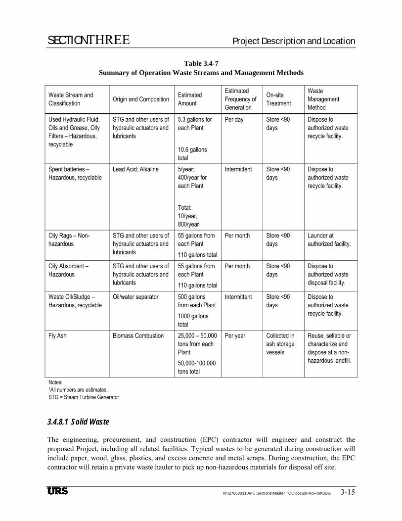
Table 3.4-7 Summary of Operation Waste Streams and Management Methods
Waste Stream and Classification Origin and Composition Estimated
Amount
Estimated Frequency of Generation
On-site Treatment
Waste Management Method
Used Hydraulic Fluid, Oils and Grease, Oily Filters – Hazardous, recyclable
STG and other users of hydraulic actuators and lubricants
5.3 gallons for each Plant 10.6 gallons total
Per day Store <90 days
Dispose to authorized waste recycle facility.
Spent batteries – Hazardous, recyclable
Lead Acid; Alkaline 5/year; 400/year for each Plant Total: 10/year; 800/year
Intermittent Store <90 days
Dispose to authorized waste recycle facility.
Oily Rags – Non-hazardous
STG and other users of hydraulic actuators and lubricants
55 gallons from each Plant 110 gallons total
Per month Store <90 days
Launder at authorized facility.
Oily Absorbent – Hazardous
STG and other users of hydraulic actuators and lubricants
55 gallons from each Plant 110 gallons total
Per month Store <90 days
Dispose to authorized waste disposal facility.
Waste Oil/Sludge – Hazardous, recyclable
Oil/water separator 500 gallons from each Plant 1000 gallons total
Intermittent Store <90 days
Dispose to authorized waste recycle facility.
Fly Ash Biomass Combustion 25,000 – 50,000 tons from each Plant 50,000-100,000 tons total
Per year Collected in ash storage vessels
Reuse, sellable or characterize and dispose at a non-hazardous landfill.
Notes: 1All numbers are estimates. STG = Steam Turbine Generator
3.4.8.1 Solid Waste
The engineering, procurement, and construction (EPC) contractor will engineer and construct the proposed Project, including all related facilities. Typical wastes to be generated during construction will include paper, wood, glass, plastics, and excess concrete and metal scraps. During construction, the EPC contractor will retain a private waste hauler to pick up non-hazardous materials for disposal off site.
SECTIONTHREE Project Description and Location
3-16 W:\27658031\AFC Sections\Master TOC.doc\20-Nov-08\SDG
During operations, the largest volume of solid waste generated by the Project will be the ash produced during biomass combustion. Currently, ash generated by existing biomass facilities in California are sold for a variety of purposes that include supplements for the manufacture of aggregate and concrete, soil mineral supplements and bedding material for livestock pens, and other uses. All of the ash produced from the facility is anticipated to be marketable for these purposes. These are traditional uses for ash produced by existing biomass facilities throughout the state, burning the same fuels to be used as the proposed Project. Annual ash production from the facility is anticipated to be in the range of 10,000 to 25,000 tpy from each Plant, or a total annual production of less than 50,000 tpy. Based on a truck loading capacity of 20 tons of ash, and 10 hours of operations 5 days/week, this represents about 10 trucks/day or 1 truck/hour.
Ash produced at the facility will be stored on site temporarily in closed silos, to be regularly loaded into trucks for transportation off site. If beneficial uses for all of the ash cannot be found, depending on whether the excess ash is characterized as non-hazardous or hazardous waste, it will be disposed of in accordance with applicable LORS in either a Class I or Class III Landfill, respectively. The Kettleman Hills Landfill, located just over 20 miles south of the site, would accept hazardous or non-hazardous ash.
3.4.8.2 Hazardous Waste
Hazardous wastes will be generated during construction and operation of the proposed Project. Most of the hazardous wastes generated during construction (e.g., paint and primer, thinners, solvents) will be recycled (see Table 3.4-6). Hazardous solid and liquid waste streams generated during operations include used hydraulic fluids, oils, greases, filters, etc.; spent cleaning solutions; and spent batteries. These hazardous wastes will be recycled (see Table 3.4-7).
Each Plant is designed to have one OWS. All drains from transformers, turbines, skids, and other mechanical equipment and potential oily “contact” areas will be routed to the OWS. Discharge oil will be stored in 500-gallon tanks fitted with transfer pumps for loading trucks for offsite disposal. Clear water from the OWS will be recovered and directed to the water treatment system.
3.4.8.3 Storm Water Management
The solar Plants are designed with a zero discharge waste/storm water design. The solar fields will be graded to retain storm water in the center of the field for natural evaporation and percolation. A lined evaporation pond will be installed for evaporation of waste water.
3.4.9 Management and Disposal of Hazardous Materials
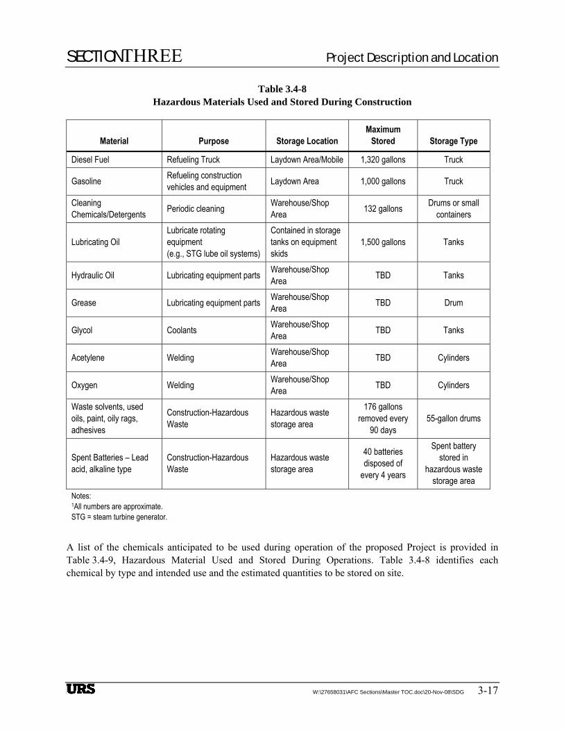
Hazardous materials to be used during construction include gasoline, diesel fuel, oil, and small amounts of lubricants cleaners, solvents and adhesives. There are no feasible alternatives to these materials for construction or operation of construction vehicles and equipment. No acutely hazardous materials (AHM) will be used or stored on site during construction. No storage of hazardous materials is planned outside of the Plant sites. A summary of hazardous materials to be used and stored for construction of the proposed Project is provided in Table 3.4-8, Hazardous Materials Used and Stored During Construction.
SECTIONTHREE Project Description and Location
W:\27658031\AFC Sections\Master TOC.doc\20-Nov-08\SDG 3-17
Table 3.4-8 Hazardous Materials Used and Stored During Construction
Material Purpose Storage Location Maximum
Stored Storage Type
Diesel Fuel Refueling Truck Laydown Area/Mobile 1,320 gallons Truck
Gasoline Refueling construction vehicles and equipment Laydown Area 1,000 gallons Truck
Cleaning Chemicals/Detergents Periodic cleaning Warehouse/Shop
Area 132 gallons Drums or small containers
Lubricating Oil Lubricate rotating equipment (e.g., STG lube oil systems)
Contained in storage tanks on equipment skids
1,500 gallons Tanks
Hydraulic Oil Lubricating equipment parts Warehouse/Shop Area TBD Tanks
Grease Lubricating equipment parts Warehouse/Shop Area TBD Drum
Glycol Coolants Warehouse/Shop Area TBD Tanks
Acetylene Welding Warehouse/Shop Area TBD Cylinders
Oxygen Welding Warehouse/Shop Area TBD Cylinders
Waste solvents, used oils, paint, oily rags, adhesives
Construction-Hazardous Waste
Hazardous waste storage area
176 gallons removed every
90 days 55-gallon drums
Spent Batteries – Lead acid, alkaline type
Construction-Hazardous Waste
Hazardous waste storage area
40 batteries disposed of
every 4 years
Spent battery stored in
hazardous waste storage area
Notes: 1All numbers are approximate. STG = steam turbine generator.
A list of the chemicals anticipated to be used during operation of the proposed Project is provided in Table 3.4-9, Hazardous Material Used and Stored During Operations. Table 3.4-8 identifies each chemical by type and intended use and the estimated quantities to be stored on site.

SECTIONTHREE Project Description and Location
3-18 W:\27658031\AFC Sections\Master TOC.doc\20-Nov-08\SDG
Table 3.4-9 Hazardous Materials Used and Stored During Operations
Chemical Use Storage Location Maximum
Stored Storage Type
Aqueous ammonia ([19%] NH4 (OH))
NOx emissions control SCR Unit 40,000 gallons for each Plant
Aboveground tank
Heat Transfer Fluid (Therminol VP-1)
Transfers energy from solar field to power block
Plant System, Power Block Area
185,000 gallons for each Plant
Vessels within the plant circulation loop system
Chlorine Water treatment Water Treatment Area 500 gallons Tank Hydrochloric Acid Water treatment Water Treatment Area TBD Tank Cation and Anion Beads Water treatment Water Treatment Area TBD TBD Diesel Fuel Firewater pump driver Firewater Skid 300 gallons for
each plant Tank
Cleaning Chemicals/Detergents
Periodic cleaning Warehouse/shop area 500 liters for each plant
55-gallon drums and small containers
Corrotrol OS5300 Oxygen scavenger Water Treatment Building
10,000 gallons for each plant
Tank
Lubricating Oil Lubricate rotating equipment (e.g., STG lube oil systems)
Contained in storage tanks on equipment skids
1,585 gallons each plant 3,170 gallons total
Tanks
Laboratory Reagents Water laboratory analysis Water Treatment Building
4 liters Small containers
Mineral Transformer Insulating Oil
Generator Step-Up (GSU) transformers
Transformer Area 11,000 gallons per GSU 22,000 gallons total
Contained within transformers and electrical switches
Mineral Transformer Insulating Oil
Standby Transformer Standby Transformer Area
4,000 gallons Contained within transformers and electrical switches
Mineral Transformer Insulating Oil
Auxiliary Transformers Auxiliary Transformer Area
3,000 gallon per auxiliary transformer
Contained within transformers and electrical switches
Propylene Glycol Coolant Antifreeze Power Block 55 gallons for each plant
Drum

SECTIONTHREE Project Description and Location
Table 3.4-9 Hazardous Materials Used and Stored During Operations
(Continued)
W:\27658031\AFC Sections\Master TOC.doc\20-Nov-08\SDG 3-19
Chemical Use Storage Location Maximum
Stored Storage Type
Acetylene, Oxygen, Other Welding Gases Maintenance Welding Shop/warehouse TBD Cylinders of
various volumes
Spent batteries – Lead Acid, Alkaline
Hazardous Waste Hazardous Waste Storage Area Intermittent
Batteries stored in waste storage area
Oily Absorbent Hazardous Waste Hazardous Waste Storage Area
55 gallons per month for each plant
Drum
Waste Oil/Sludge – from Oil/Water Separator
Hazardous Waste Hazardous Waste Storage Area
500 gallons for each plant
Oil/Water Separator
Notes: 1All numbers are approximate. STG = steam turbine generator
3.4.10 Fire Protection System
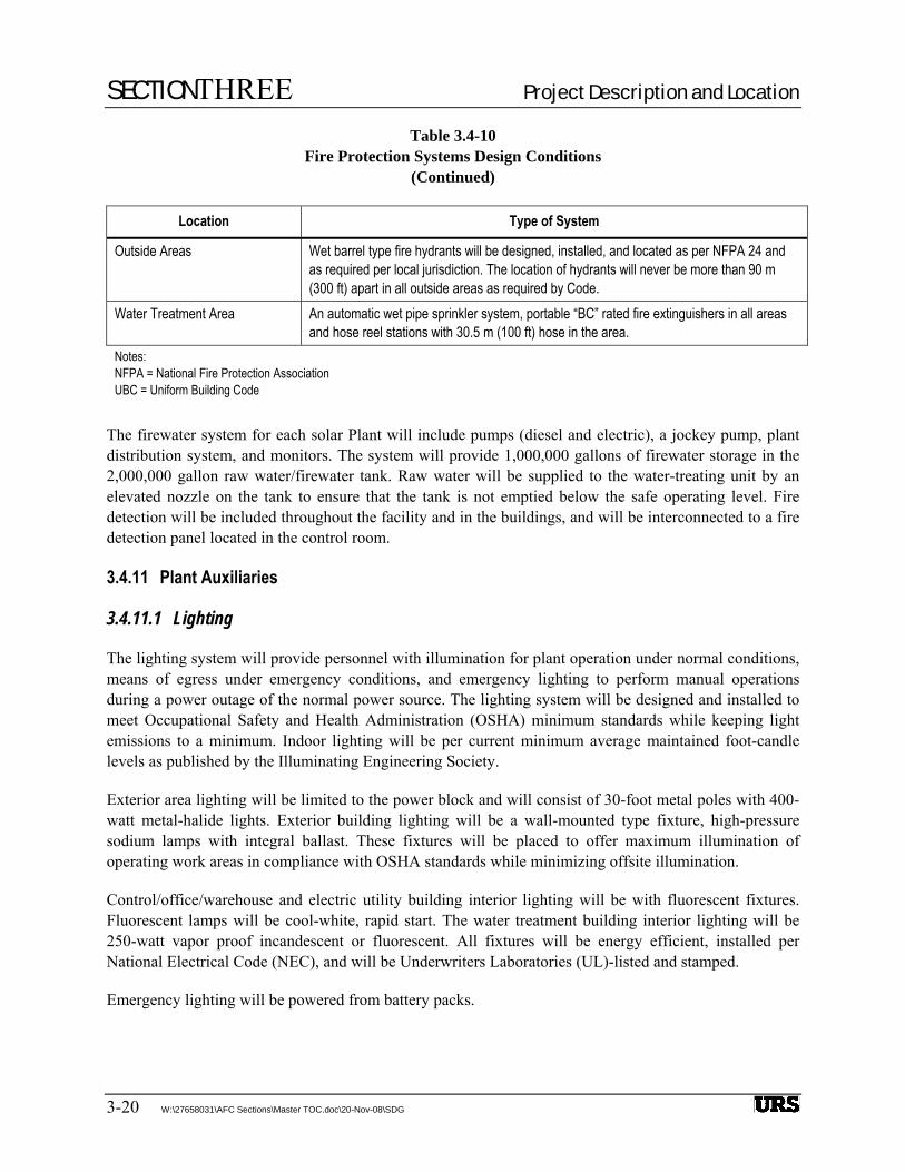
The fire protection system will be designed to protect personnel, limit property loss, and to reduce plant downtime in the event of a fire. The fire protection system is summarized in Table 3.4-10, Fire Protection Systems Design Conditions. The fire protection system will include automatic detection and suppression systems installed in the combustion turbine enclosures, automatic suppression systems installed for the control room, gas compressor building, warehouse, etc. Transformer protection will be provided by separation and firewalls.
Table 3.4-10 Fire Protection Systems Design Conditions
Location Type of System
Buildings Automatic clean agent system per NFPA 2001 for project control room and substation control room, wet/dry/pre-action sprinkler system for warehouse/office buildings. Note: The fixed fire systems will be provided as required by local jurisdiction or UBC. Hose stations and portable extinguishers will be provided throughout buildings as required by Code. Detection system and fire alarm pull stations will be provided for the Control Room, combustion turbine inlet filter area, and the switchgear room. Pull stations shall be located in buildings as required by Code.
Steam Turbine/Generators CO2 system as defined NFPA will be provided for the steam turbine/generators. Transformers Separation and firewalls.
SECTIONTHREE Project Description and Location
Table 3.4-10 Fire Protection Systems Design Conditions
(Continued)
3-20 W:\27658031\AFC Sections\Master TOC.doc\20-Nov-08\SDG
Location Type of System
Outside Areas Wet barrel type fire hydrants will be designed, installed, and located as per NFPA 24 and as required per local jurisdiction. The location of hydrants will never be more than 90 m (300 ft) apart in all outside areas as required by Code.
Water Treatment Area An automatic wet pipe sprinkler system, portable “BC” rated fire extinguishers in all areas and hose reel stations with 30.5 m (100 ft) hose in the area.
Notes: NFPA = National Fire Protection Association UBC = Uniform Building Code
The firewater system for each solar Plant will include pumps (diesel and electric), a jockey pump, plant distribution system, and monitors. The system will provide 1,000,000 gallons of firewater storage in the 2,000,000 gallon raw water/firewater tank. Raw water will be supplied to the water-treating unit by an elevated nozzle on the tank to ensure that the tank is not emptied below the safe operating level. Fire detection will be included throughout the facility and in the buildings, and will be interconnected to a fire detection panel located in the control room.
3.4.11 Plant Auxiliaries
3.4.11.1 Lighting
The lighting system will provide personnel with illumination for plant operation under normal conditions, means of egress under emergency conditions, and emergency lighting to perform manual operations during a power outage of the normal power source. The lighting system will be designed and installed to meet Occupational Safety and Health Administration (OSHA) minimum standards while keeping light emissions to a minimum. Indoor lighting will be per current minimum average maintained foot-candle levels as published by the Illuminating Engineering Society.
Exterior area lighting will be limited to the power block and will consist of 30-foot metal poles with 400-watt metal-halide lights. Exterior building lighting will be a wall-mounted type fixture, high-pressure sodium lamps with integral ballast. These fixtures will be placed to offer maximum illumination of operating work areas in compliance with OSHA standards while minimizing offsite illumination.
Control/office/warehouse and electric utility building interior lighting will be with fluorescent fixtures. Fluorescent lamps will be cool-white, rapid start. The water treatment building interior lighting will be 250-watt vapor proof incandescent or fluorescent. All fixtures will be energy efficient, installed per National Electrical Code (NEC), and will be Underwriters Laboratories (UL)-listed and stamped.
Emergency lighting will be powered from battery packs.

SECTIONTHREE Project Description and Location
W:\27658031\AFC Sections\Master TOC.doc\20-Nov-08\SDG 3-21
3.4.11.2 Electrical Grounding
The electrical system will be susceptible to ground faults, lightning, and switching surges that can result in high voltage spikes. The station grounding system will provide an adequate path to permit the dissipation of current created by these events, protecting personnel and equipment. The facility and substation grounding system will be tied solidly into all facility equipment.
The ground grid will be located underground and will be sized in accordance with NEC, using a minimum #4/0 AWG bare copper wire size. Grounded neutral conductors are protected by non-metallic conduit where conductors run exposed above grade.
Ground rods will be copper-clad steel, not less than 2 cm (¾-inch) in diameter and 3.05 m (10 feet) long. Rods will be driven into the ground and interconnected 76.2 cm (30 inches) below grade. Rods will be added or lengthened and interconnected as required to meet the specified ground resistance. Above-grade grounding connections will be made using exothermic welds or compression connectors bolted to skidded equipment or structural steel.
3.4.11.3 Cathodic and Lightning Protection
The cathodic protection system will be designed and installed to control electrochemical corrosion of exterior surfaces of underground carbon steel and stainless steel. Bottoms of soil or sand pad mounted steel tanks, exterior surfaces of underground ductile or cast iron pipe will be protected against corrosion. The type of cathodic protection system (galvanic or impressed current) will be based on soil characteristics, the amount of material to be protected, and the interference effects of any nearby cathodic protection systems.
Lightning protection will be as per National Fire Protection Association (NFPA) 780 guidelines, and will be provided where required for plant structures and pumps. Specific equipment protected will be determined by a lightning protection study.
3.4.11.4 Distributed Control System
Each Plant will incorporate a distributed control system (DCS) to provide monitoring and control of the power block, biomass facilities and related balance of plant (BOP) systems. The DCS will be designed for facility operation from each main control room by a single operator. The DCS workstations will enable the operator to view real-time instrumentation status of the plants equipment. Interactive control will be provided through human machine interface (HMI) screens located on the computer workstations. Event and alarm data will be continuously logged and stored in a redundant database for reports, printout, and historical analyses.
3.4.11.5 Service Air System
The service air system will supply compressed air to hose connections located at intervals throughout each proposed power plant. Compressors deliver compressed air at a regulated pressure to the service air piping network.

SECTIONTHREE Project Description and Location
3-22 W:\27658031\AFC Sections\Master TOC.doc\20-Nov-08\SDG
3.4.11.6 Instrument Air System
The instrument air system will provide dry, filtered air to pneumatic operators and devices throughout the proposed power plant. Air from the service air system will be dried, filtered, and pressure regulated prior to delivery to the instrument air piping network.
3.4.11.7 HVAC
Controlled HVAC will be provided for the administration buildings, warehouse and maintenance facilities, maintaining an interior temperature suitable for personnel comfort. HVAC controls will be provided for sensitive areas (e.g., control rooms, electronics storage, etc.) as required for equipment protection and personnel comfort.
3.5 FACILITY CIVIL/STRUCTURAL FEATURES
3.5.1 Power Block, Biomass Facilities and BOP Equipment
The power block, biomass facilities, cooling towers, and transformers will be supported at grade elevation on reinforced concrete mat foundations. Balance-of-plant mechanical and electrical equipment will be supported at grade elevation on individual reinforced concrete foundation pads.
The types of foundations and pilings, if required, will be as recommended by the Geotechnical Engineer in accordance with the final Geotechnical Report. Design of concrete foundations will be in accordance with American Concrete Institute (ACI) 318 and the California Building Code (CBC).
3.5.2 Buildings
Facility buildings will be pre-fabricated, pre-engineered metal buildings designed in accordance with the appropriate building codes. Buildings will be finished in shades of beige and brown. Complete gutters and downspouts will be provided. Project buildings include the following:
• Control/office buildings.
• Warehouse and shops.
• Turbine building with electric utilities.
• Biomass storage building.
Foundation systems will be designed with an allowable soil bearing capacity as recommended by the Geotechnical Engineer in accordance with the final Geotechnical Report.
3.5.3 Yard Tanks
Yard storage tanks for the Project will include the following:
• One 1,000,000-gallon treated city water effluent carbon steel tank.

SECTIONTHREE Project Description and Location
W:\27658031\AFC Sections\Master TOC.doc\20-Nov-08\SDG 3-23
• One 2,000,000-gallon raw well water – firewater carbon steel tank.
• One 200,000-gallon raw city water effluent carbon steel tank.
• Two 100,000-gallon (Steam Generation System) demineralized stainless steel water tanks.
• Two- 50,000-gallon (Auxiliary Cooling System) demineralized stainless steel water tanks.
• Two-25,000-gallon potable water stainless steel tanks.
• One 500-gallon waste oil tank.
• Four- 20,000-gallon ammonia storage tanks.
The water storage tanks will be shop fabricated and/or field erected according to the requirements of American Water Works Association (AWWA) D103. Welded steel tanks will be used for oil storage. Welders will be qualified per American Society of Mechanical Engineers (ASME) Section IX. Each tank will be equipped with roof and shell access manways, 24-inch wide spiral stairs and roof platform with handrails, and other appurtenances as required for the service.
3.5.4 Roads
The two Plants will require approximately 7.5 miles of roadways. The roads will be approximately 20 feet wide and made of asphalt-concrete surface with a gravel base. Parking lots will be made of asphalt-concrete surface with a gravel base.
3.5.5 Site Security
The facility will be fenced with a minimum 10-foot chain-link fence with privacy lattice around the perimeter. Entrance to the facility will be through one 7.3 m (24 feet) wide motorized gate manned by a security guard. Site security includes motion activated cameras, remotely controlled from the control room.
3.5.6 Site Grading and Drainage
Grades will be established to minimize the amount of earthwork required to construct the facilities and to maintain control of stormwater runoff. All areas disturbed during construction will be graded to a smooth surface. Selected area will be covered with appropriate material, as conditions require (e.g., asphalt concrete for road base and gravel for other surfaces). Finish grading will be performed to conform to the finished design elevations for surface drainage and to prepare the areas for the specified surface finishes.
Rainfall from each plant’s solar field will continue to be drained by sheet flow. Drainage will be controlled through infiltration basins to allow the rainfall to be absorbed into the ground replenishing local ground water levels.
Rainfall from vehicle parking and paved areas in the power block will be collected and directed to an oil/water separator prior to discharge to the raw water tank for recovery.

SECTIONTHREE Project Description and Location
3-24 W:\27658031\AFC Sections\Master TOC.doc\20-Nov-08\SDG
3.5.7 Interconnection to Electrical Grid
The transmission line will be an approximately 6 miles long 230 kV (AFC-C7). It begins in the middle of the Project site at each dead-end structure found just beyond the turbine/generator and the 13.8 to 230 kV step-up transformer. It travels to the east site boundary then either north or south to the respective site corner, then due east for 5 miles before it travels north to Gates Substation. It then connects to an existing 230 kV bus in the substation.
The overhead 230 kV transmission conductors to the physical connection with the existing Gates Substation will be supported by a dead-end structure in each Plant’s switchyard and multiple H frame using 85-foot 230 kV type A wood poles (three sets of insulators in horizontal configuration with a spacing of about 6.7 m (22 feet) between the phases).
The Projects are in the interconnection queue with the CAISO, and are scheduled to undergo the new interconnection procedure starting November 2008. All interconnection and feasibility studies required under the Large Generator Interconnection Process (LGIP) are scheduled to be completed within the Phase I Study of the Transition Cluster designated by FERC. The Phase I Study of the Transition Cluster will be completed by July 31, 2009, upon which the Large Generator Interconnection Agreement will be signed. The executed agreement and proof of payment to CAISO are provided in Appendix A-5, Executed Large Generator Interconnection Study Process Agreement and Proof of Payment of the Study Deposit to CAISO.
3.6 PROJECT CONSTRUCTION
3.6.1 Power Plant Facility
Project construction, from site preparation and grading to full commercial operation, is expected to take approximately 15 months. Major milestones are listed in Table 3.6-1.
Heavy construction will be scheduled between 7:00 a.m. and 5:00 p.m., Monday through Friday. Additional hours may be necessary to make up schedule deficiencies or to complete critical construction activities.
Table 3.6-1 Project Schedule Major Milestones
Activity Date
Begin Construction 1st Quarter 2010 Start Up and Commissioning: SJS 1 Plant 1st Quarter 2011 Start Up and Commissioning: SJS 2 Plant 2nd Quarter 2011

SECTIONTHREE Project Description and Location
W:\27658031\AFC Sections\Master TOC.doc\20-Nov-08\SDG 3-25
3.6.1.1 Construction Workforce
The projected monthly construction labor is presented in Table 3.6-2 for the 15-month construction period. The size of the workforce on site will range from 29 during month 1 to a peak of 744 during month 12. SJS 1&2 LLC and the local union will enter into a project labor agreement (PLA) to ensure that a sufficient supply of skilled craft workers is available at the Project to perform construction related activities. SJS 1&2 LLC will provide approximately $138.24 million (in 2008 dollars) in construction payroll. During construction, the average salary per employee is expected to be $30-40 per hour, including benefits.
Table 3.6-2 Construction Labor
Projected Monthly Manpower (by Craft)
Months After Notice to Proceed Craft Type
1 2 3 4 5 6 7 8 9 10 11 12 13 14 15
Laborers 3 5 5 6 23 36 60 64 80 100 110 82 70 52 40 Operators 5 9 18 15 10 16 30 20 26 30 24 20 15 18 12 Electricians 3 4 4 4 10 17 25 32 70 87 100 105 105 78 55 Pipe fitters 1 2 5 5 10 15 28 40 50 92 100 105 98 85 75 Ironworkers 3 4 4 6 10 18 25 30 40 76 72 75 70 46 33 Boilermakers 5 8 14 18 30 50 50 30 25 Carpenters 1 2 2 2 10 17 20 24 30 50 37 37 40 38 24 Cement Work 3 4 9 10 15 29 35 55 60 60 55 70 50 35 20 Millwrights 10 15 25 25 50 35 35 25 Truck Drivers 2 4 8 12 16 20 24 35 45 45 45 65 55 40 25
Total Craft Labor per Month 21 34 55 60 104 168 252 318 430 583 598 659 588 457 334
Field Non-Manual 8 10 15 20 25 40 50 60 65 70 75 85 85 70 60
Total Manpower Per Month 29 44 70 80 129 208 302 378 495 653 678 744 673 527 394
3.6.1.2 Construction Site Security
During construction, the facility will be fenced with a minimum 10-foot chain-link fence with privacy lattice around the perimeter. Entrance to and egress from the facility will be through two 24-foot wide motorized gates manned by a security guard.

SECTIONTHREE Project Description and Location
3-26 W:\27658031\AFC Sections\Master TOC.doc\20-Nov-08\SDG
3.6.1.3 Site Mobilization
Site facilities and amenities will be established during the first month of the solar field build out. The majority of these will be located in the construction laydown area located in the center of the Project site as illustrated on Figure 3.6-1. These will consist of site offices, restroom facilities, meal rooms, parking areas, vehicle marshalling areas, and construction material/equipment storage areas. Construction power to the temporary site facilities will be provided by mobile diesel-driven generator sets.
3.6.1.4 Site Preparation
The planned location of the facility is generally flat, at an elevation of approximately 590 feet msl. The power block areas will be graded to provide a level site area for the biomass, STGs, cooling towers, buildings, tanks, switchyard, and all associated facilities at approximately 590 feet above msl. Movement of material will be limited to that required for a level site for the equipment and facilities. Cut-and-fill is anticipated, and material available on site is expected to be adequate for this requirement, subject to final geotechnical evaluation.
Project site topography is predominantly flat with a slight downward slope to the south and west. Construction of the solar field requires level ground, so the solar field blocks will be prepared in a terraced configuration. This approach will best achieve the necessary leveled effects while minimizing the amount of cut-and-fill operations. Any material cut from the site in preparation for construction will be used to improve adjacent areas within the Project site.
Site clearing and grading will occur during the first six months of construction. Based on the Grading and Drainage Plan, 6,200,000 cubic yards of cut and 6,200,000 cubic yards of fill are required. SJS 1 will be prepared first, beginning at the eastern site boundary moving west. Preparation of SJS 2 will follow, beginning at the western site boundary moving east (see Figure 3.6-1). This will be undertaken on a continuous rolling basis across the site. There will be some overlap in these operations.
The earthworks process will be undertaken using standard contractor equipment. This will consist of dozers, elevating scrapers, hydraulic excavators, tired loaders, compacting rollers, and dump trucks.
3.6.1.5 Foundations
The SCAs in the solar field will be supported on pile foundations. Excavations for foundations would be made with power drilling equipment. A vehicle-mounted power auger would be used to excavate for the SCA foundations. Footings would be installed by placing reinforcing steel and an anchor bolt cage into each foundation hole, positioning the bolt cage, and encasing it in concrete. Spoil material would be used for fill where suitable.
Foundation excavations will be prepared as required for the power block, biomass facilities, transformers and other heavy equipment. Prior to excavation, underground structures will be located and protected or removed. Deep foundations may be required in limited locations within the power block and biomass facilities to support heavy equipment with large overturning moments (e.g., exhaust stacks). Cast-in-drilled-hole (CIDH) or precast-prestressed concrete piles may be used, as determined by the final geotechnical investigation and foundation design.
SECTIONTHREE Project Description and Location
W:\27658031\AFC Sections\Master TOC.doc\20-Nov-08\SDG 3-27
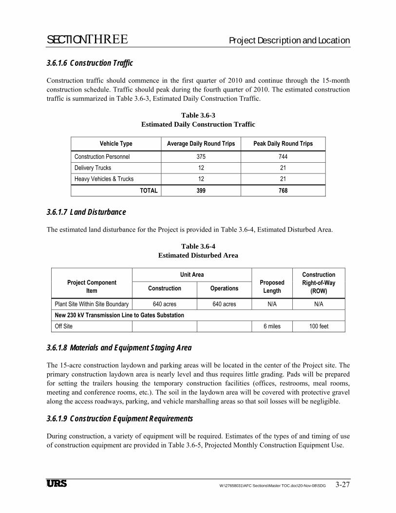
3.6.1.6 Construction Traffic
Construction traffic should commence in the first quarter of 2010 and continue through the 15-month construction schedule. Traffic should peak during the fourth quarter of 2010. The estimated construction traffic is summarized in Table 3.6-3, Estimated Daily Construction Traffic.
Table 3.6-3 Estimated Daily Construction Traffic
Vehicle Type Average Daily Round Trips Peak Daily Round Trips
Construction Personnel 375 744 Delivery Trucks 12 21 Heavy Vehicles & Trucks 12 21
TOTAL 399 768
3.6.1.7 Land Disturbance
The estimated land disturbance for the Project is provided in Table 3.6-4, Estimated Disturbed Area.
Table 3.6-4 Estimated Disturbed Area
Unit Area Project Component
Item Construction Operations Proposed
Length
Construction Right-of-Way
(ROW)
Plant Site Within Site Boundary 640 acres 640 acres N/A N/A New 230 kV Transmission Line to Gates Substation Off Site 6 miles 100 feet
3.6.1.8 Materials and Equipment Staging Area
The 15-acre construction laydown and parking areas will be located in the center of the Project site. The primary construction laydown area is nearly level and thus requires little grading. Pads will be prepared for setting the trailers housing the temporary construction facilities (offices, restrooms, meal rooms, meeting and conference rooms, etc.). The soil in the laydown area will be covered with protective gravel along the access roadways, parking, and vehicle marshalling areas so that soil losses will be negligible.
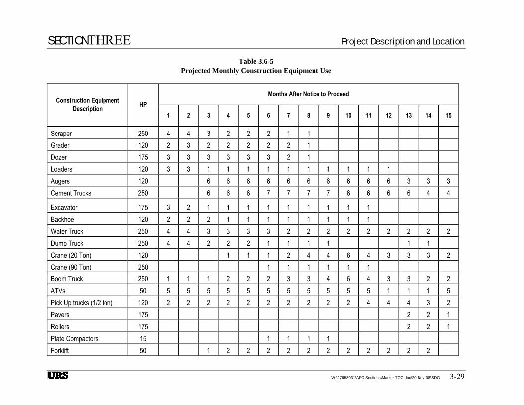
3.6.1.9 Construction Equipment Requirements
During construction, a variety of equipment will be required. Estimates of the types of and timing of use of construction equipment are provided in Table 3.6-5, Projected Monthly Construction Equipment Use.

SECTIONTHREE Project Description and Location
3-28 W:\27658031\AFC Sections\Master TOC.doc\20-Nov-08\SDG
This page intentionally left blank
SECTIONTHREE Project Description and Location
W:\27658031\AFC Sections\Master TOC.doc\20-Nov-08\SDG 3-29
Table 3.6-5 Projected Monthly Construction Equipment Use
Months After Notice to Proceed Construction Equipment
Description HP 1 2 3 4 5 6 7 8 9 10 11 12 13 14 15
Scraper 250 4 4 3 2 2 2 1 1 Grader 120 2 3 2 2 2 2 2 1 Dozer 175 3 3 3 3 3 3 2 1 Loaders 120 3 3 1 1 1 1 1 1 1 1 1 1 Augers 120 6 6 6 6 6 6 6 6 6 6 3 3 3 Cement Trucks 250 6 6 6 7 7 7 7 6 6 6 6 4 4
Excavator 175 3 2 1 1 1 1 1 1 1 1 1 Backhoe 120 2 2 2 1 1 1 1 1 1 1 1 Water Truck 250 4 4 3 3 3 3 2 2 2 2 2 2 2 2 2 Dump Truck 250 4 4 2 2 2 1 1 1 1 1 1 Crane (20 Ton) 120 1 1 1 2 4 4 6 4 3 3 3 2 Crane (90 Ton) 250 1 1 1 1 1 1 Boom Truck 250 1 1 1 2 2 2 3 3 4 6 4 3 3 2 2 ATVs 50 5 5 5 5 5 5 5 5 5 5 5 1 1 1 5 Pick Up trucks (1/2 ton) 120 2 2 2 2 2 2 2 2 2 2 4 4 4 3 2 Pavers 175 2 2 1 Rollers 175 2 2 1 Plate Compactors 15 1 1 1 1 Forklift 50 1 2 2 2 2 2 2 2 2 2 2 2

SECTIONTHREE Project Description and Location
Table 3.6-5 Projected Monthly Construction Equipment Use
(Continued)
3-30 W:\27658031\AFC Sections\Master TOC.doc\20-Nov-08\SDG
Months After Notice to Proceed Construction Equipment
Description HP 1 2 3 4 5 6 7 8 9 10 11 12 13 14 15
Welder 50 1 1 1 1 1 1 1 1 1 1 Generator 50 1 1 1 1 1 2 2 3 3 3 3 2 Aerial Lift 50 1 1 1 1 1 1 1 1 1 1 Total: 33 33 38 40 40 44 43 43 42 43 42 33 34 30 26

SECTIONTHREE Project Description and Location
W:\27658031\AFC Sections\Master TOC.doc\20-Nov-08\SDG 3-31
3.7 FACILITY OPERATION
3.7.1 Operation schedule
The two plants will each be sized for a nominal 53.4 MW of solar generation, complemented by up to 40 MW of conventional biomass-capable production. The biomass operation will be subordinate to the solar field, supplementing solar production during non-solar and reduced solar hours. The biomass facilities will operate at night and during hours of reduced solar intensity. In winter, it is anticipated the biomass facilities will run 24 hours a day at varying capacities, and during the summer, will be shut down for an extended period each day. The biomass facilities will operate at an annual average of approximately 75% of maximum capacity. Figure 3.7-1 illustrates the planned operation of the solar and biomass components for each hour of the day over a typical calendar year.
Since a substantial portion of the generation from the proposed Project will depend on solar radiation, the Plants are both anticipated to be classified as “as-available resources.” When solar energy is not available, the Plants will be limited to 40 MW net production on biomass. Replacement of solar power during cloudy periods or changing weather conditions will be subject to the operational transition of the Plants from solar to biomass production, and back to solar. When operational, the Plants are typically intended to produce the highest sustainable output of 40 – 53.4 MW net. The Project will be priority dispatched by PG&E through day ahead, hour ahead, and real-time scheduling, as required to meet California market demands. The market will dictate unit operations. The proposed Project will be cycled daily, harvesting solar energy during daylight hours and biomass energy during the night, resulting in 774,000 MW-hours produced per year, on average.
3.7.2 Operation staffing
The completed Project is expected to have a combined total staff of 60. The staff will commute to the Project from surrounding areas (e.g., Coalinga, Fresno, and Bakersfield). The staff will consist of 10 shared supervisory, general, and administrative positions; 30 operations and maintenance personnel in the power block and biomass facilities; and 20 maintenance personnel in the solar field. The Project will be staffed 24 hours per day, with the majority of the staff on site during daytime operating hours. The annual combined operation payroll will be approximately $4.2 million for the two Plants. The ten administrative staff will work during the day to support both plants. Operations will run each solar plant with three 3-person crews working 12 hour shifts on a rotating basis, for a total of 24 operators for the Project. A night maintenance crew and two mirror washing crews will work primarily at night supporting both plants
3.7.3 Operations deliveries and pick ups
Biomass fuel will be delivered to the Project site Monday through Friday between 7 a.m. and 5 p.m. Daily biomass deliveries for each plant will average 67 trucks, with peak days having 80 trucks. Ash will be removed by an average of 10 trucks each day. Raw materials such as ammonia, lime, and limestone will average one delivery per week.
SECTIONTHREE Project Description and Location
3-32 W:\27658031\AFC Sections\Master TOC.doc\20-Nov-08\SDG
3.8 SAFETY AND RELIABILITY
3.8.1 Safety Precautions and Emergency Systems
Safety precautions and emergency systems will be implemented as part of the design and construction of the proposed Project to ensure safe and reliable operation of Project facilities. Administrative controls will include classroom and hands-on training in operating and maintenance procedures and general safety items, and a well-planned maintenance program. These will work with the system design and monitoring features to enhance safety and reliability.
Safety, auxiliary, and emergency systems will consist of lighting, grounding, electricity backup for controls, fire and hazardous materials safety systems, security systems, and steam safety systems. Each Plant will include its own utilities and services such as emergency power, Plant and instrument air, fire suppression, and potable water systems.
3.8.2 Facility Reliability
Operations and maintenance procedures will be implemented which are consistent with industry practices to maintain the useful life of the Plants and all components. At the conclusion of Plant commissioning when SJS 1&2 are each declared operational, it is expected that the Plants will be fully available for the entire projected 20-year life, with the exception of normal scheduled maintenance outages and occasional unscheduled outages.
The biomass system at each Plant will have two identical units, each sized for approximately 20 MW net output. The redundancy allows for operational flexibility when the solar energy production requires biomass supplement at less than full load. The two systems can be operated independently and will be alternated to allow routine and preventative maintenance on the biomass feed system, ash systems and the auxiliary facilities. The solar field equipment, including pumps, mechanical drives, controls, etc., will be maintained on a nightly basis.
3.8.3 Natural Hazards
The primary natural hazards at this site are seismic, flooding, wind, blowing dust, heat, and fire.
3.8.3.1 Seismic Hazards
Structures and their foundations and equipment anchors will be designed according to the 2007 CBC, and the Fresno County Building Code. Should there be a conflict in code requirements, the more conservative requirements will govern. In addition, all substation equipment will meet requirements of the IEEE 693-1997 Recommended Practice for Seismic Design of Substations.
3.8.3.2 Flooding
The Project site is not subject to flooding and is not within the 100-year flood zone.

SECTIONTHREE Project Description and Location
W:\27658031\AFC Sections\Master TOC.doc\20-Nov-08\SDG 3-33
3.8.3.3 Wind and Dust Hazards
All buildings will be designed for wind loads stated in the current edition of the CBC and the Fresno County Building Code. In addition, particular care will be taken to minimize sand and grit intrusion for areas that will be occupied by personnel and for the main equipment locations.
If needed during construction, techniques to control windblown dust will include the use of water over the surface to enhance dust control, constructing temporary enclosures to reduce wind effect, and timely revegetation of barren construction areas.
3.8.3.4 Heat
All buildings will be designed with the appropriate climate controlled environment for protection of both personnel and equipment. This will include air conditioning, insulation, landscaping, overhead covers, ventilation, and appropriate use of glass and color selection to reduce heat.
3.8.3.5 Fire
SJS 1&2 are located in a moderate fire hazard zone and outside regions where the risk of wildland fires are considered significant.
3.8.4 Emergency Systems and Safety Precautions
Safety precautions and emergency systems will be implemented as part of the design and construction of the Project to ensure safe and reliable operation of project facilities. Administrative controls will include classroom and hands-on training in operating and maintenance procedures and general safety items, and a well-planned maintenance program. These will work with the system design and monitoring features to enhance safety and reliability.
Safety, auxiliary, and emergency systems will consist of lighting, grounding, DC backup for controls, fire and hazardous materials safety systems, security systems, and natural gas, steam, and chemical safety systems. Each Plant will include its own utilities and services such as emergency power, plant and instrument air, fire suppression, and potable water systems.
3.8.5 Safety Precautions
3.8.5.1 Worker Safety
SJS 1&2 will implement programs to assure that compliance with federal and state occupational safety and health program requirements is maintained. In addition to compliance with these programs, each Plant will identify and implement plant-specific programs that effectively assess potential hazards and mitigate them on a routine basis.
A more complete discussion of worker safety is provided in Section 5.17.

SECTIONTHREE Project Description and Location
3-34 W:\27658031\AFC Sections\Master TOC.doc\20-Nov-08\SDG
3.8.5.2 Public Health and Safety
The programs implemented to protect worker health and safety will also benefit public health and safety. Facility design will include controls and monitoring systems to minimize the potential for upset conditions that could result in public exposure to acutely hazardous materials. Potential public health impacts associated with operation of the project will be mitigated by development and implementation of an Emergency Response Plan (ERP), a HAZCOM Program, a Spill Prevention, Control, and Countermeasures (SPCC) Plan, safety programs, and employee training.
SJS1&2 will coordinate with local emergency responders, provide them with copies of the plant site ERP, conduct plant site tours to point out the location of hazardous materials and safety equipment, and encourage these providers to participate in annual emergency response drills.
3.8.6 Transmission Line Safety and Nuisance
Overhead transmission lines will be designed to meet safety requirements of the National Electric Safety Code and EPA requirement for spacing for bird wingspan. The estimated magnetic field at the edge of the right-of-way is 2.5 microteslas and the estimated electric field at the edge of the right-of-way is 1193 volts/meter. Design elements incorporated to reduce the EMF include an increase of the height of the transmission line above ground, an increase of the width of right-of-way, and a decrease in the distance between supports of the line.
3.8.7 Transmission Line Description
The 230kV overhead transmission line will be designed using H frame construction using wood poles on approximately 250-foot centers, and shall meet PG&E design criteria for light loading conditions. The line will be designed for a load of 220 MW at 0.9 power factor using ACSR Pelican 477kc mill 18/1 conductors. The right of way for the transmission will be 100 feet wide.
3.8.8 Aviation Safety
Federal Aviation Administration (FAA) Regulations, Part 77, establish standards for determining obstructions in navigable airspace and set forth requirements for notification of proposed construction. These regulations require FAA notification for any construction over 61 m (200 feet) high (above ground level). In addition, notification is required if the obstruction is lower than specified heights and falls within any restricted airspace in the approaches to airports. For airports with runways longer than 3,200 feet, the restricted space extends 20,000 feet, (3.3 nautical mi) from the runway. For airports with runways less than 3,200 feet, the restricted space extends 10,000 feet (1.7 nautical mi). For heliports, the restricted space extends 5,000 feet, (0.8 nautical mi).
Since the new transmission towers will be less than 61 m (200 feet) tall, and there are no public or military airports or heliports near enough for the Project to fall within restricted airspace, an FAA air navigation hazard review will not be necessary. The transmission line structures will pose no threat to aviation safety.

SECTIONTHREE Project Description and Location
W:\27658031\AFC Sections\Master TOC.doc\20-Nov-08\SDG 3-35
3.8.9 Electrical Clearances
High-voltage overhead transmission lines are composed of bare conductors connected to supporting structures by means of porcelain, glass, or plastic insulators. The air surrounding the energized conductor acts as the insulating medium. Maintaining sufficient clearances, or air space, around the conductors to protect the public and utility workers is paramount to the safe operation of the line. The safety clearance required around the conductors is determined by normal operating voltages, conductor temperatures, short-term abnormal voltages, windblown swinging conductors, contamination of the insulators, clearances for workers, and clearances for public safety. Minimum clearances are specified in the CPUC Df. (Ca. Pub. Util. Code) General Order 95 (GO 95). Typically, clearances are specified for the following:
• Distances between energized conductors.
• Distances between energized conductors and supporting structures.
• Distances between energized conductors and other power or communication wires on the same supporting structure, or between other power or communication wires above or below the conductors.
• Distances from energized conductors to the ground and other features such as roadways, railroads, driveways, parking lots, navigable waterways, airports, etc.
• Distances from energized conductors and buildings and signs.
• Distances from energized conductors and other parallel power lines.
3.8.10 Audible Noise and Radio Interferences
Corona may result in the production of audible noise from a transmission line. Corona is a function of the line voltage, the conductor diameter, and the condition of the conductor and suspension hardware. The electric field gradient is the rate at which the electric field changes and is directly related to the line voltage. Corona typically becomes a concern for transmission lines having voltages of 345 kV or more. Since the Plants will be connected at 230 kV, it is expected that no corona-related design issues will be encountered, and that the construction and operation of the Project will not result in any significant increase in electromagnetic field (EMF) levels or audible noise.
3.8.11 Induced Currents and Hazardous/Nuisance Shocks
The proposed 230 kV transmission interconnection will be designed and constructed in conformance with CPUC GO95 and Title 8 California Code of Regulations (CCR) 2700 requirements. Therefore, hazardous shocks are unlikely to occur as a result of Project construction or operation.
3.8.12 Electric and Magnetic Fields
Operating power lines, like the energized components of electrical motors, home wiring, lighting, and all other electrical appliances, produce EMF. The EMF produced by the AC electrical power system in the United States has a frequency of 60 Hz, meaning that the intensity and orientation of the field changes 60 times per second.
SECTIONTHREE Project Description and Location
3-36 W:\27658031\AFC Sections\Master TOC.doc\20-Nov-08\SDG
Considerable research has been conducted over the last 30 years on the possible biological and human health effects from EMF. This research has produced many studies that offer no uniform conclusions about potential harm of long-term exposure to EMF. In the absence of conclusive or evocative evidence, California has chosen not to specify maximum acceptable levels of EMF. Instead, California mandates a program of prudent avoidance whereby EMF exposure to the public is minimized by encouraging electric utilities to use low-cost techniques to reduce EMF levels.
3.9 APPLICABLE LAWS, ORDINANCES, REGULATIONS, AND STANDARDS (LORS)
The applicable LORS for each engineering discipline are included as part of the engineering design criteria appendices (see Appendix A-6, Foundation and Civil Engineering Design Criteria; Appendix A-7, Structural Engineering Design Criteria; Appendix A-8, Mechanical Engineering Design Criteria; Appendix A-9, Electrical Engineering Design Criteria; and Appendix A-10, Control Systems Engineering Design Criteria).
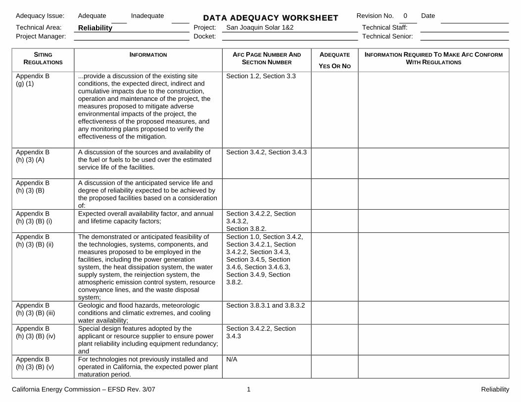
California Energy Commission – EFSD Rev. 3/07 1 Reliability
Adequacy Issue: Adequate Inadequate DATA ADEQUACY WORKSHEET Revision No. 0 Date
Technical Area: Reliability Project: San Joaquin Solar 1&2 Technical Staff: Project Manager: Docket: Technical Senior:
SITING REGULATIONS
INFORMATION AFC PAGE NUMBER AND SECTION NUMBER
ADEQUATE
YES OR NO
INFORMATION REQUIRED TO MAKE AFC CONFORM WITH REGULATIONS
Appendix B (g) (1)
...provide a discussion of the existing site conditions, the expected direct, indirect and cumulative impacts due to the construction, operation and maintenance of the project, the measures proposed to mitigate adverse environmental impacts of the project, the effectiveness of the proposed measures, and any monitoring plans proposed to verify the effectiveness of the mitigation.
Section 1.2, Section 3.3
Appendix B (h) (3) (A)
A discussion of the sources and availability of the fuel or fuels to be used over the estimated service life of the facilities.
Section 3.4.2, Section 3.4.3
Appendix B (h) (3) (B)
A discussion of the anticipated service life and degree of reliability expected to be achieved by the proposed facilities based on a consideration of:
Appendix B (h) (3) (B) (i)
Expected overall availability factor, and annual and lifetime capacity factors;
Section 3.4.2.2, Section 3.4.3.2, Section 3.8.2.
Appendix B (h) (3) (B) (ii)
The demonstrated or anticipated feasibility of the technologies, systems, components, and measures proposed to be employed in the facilities, including the power generation system, the heat dissipation system, the water supply system, the reinjection system, the atmospheric emission control system, resource conveyance lines, and the waste disposal system;
Section 1.0, Section 3.4.2, Section 3.4.2.1, Section 3.4.2.2, Section 3.4.3, Section 3.4.5, Section 3.4.6, Section 3.4.6.3, Section 3.4.9, Section 3.8.2.
Appendix B (h) (3) (B) (iii)
Geologic and flood hazards, meteorologic conditions and climatic extremes, and cooling water availability;
Section 3.8.3.1 and 3.8.3.2
Appendix B (h) (3) (B) (iv)
Special design features adopted by the applicant or resource supplier to ensure power plant reliability including equipment redundancy; and
Section 3.4.2.2, Section 3.4.3
Appendix B (h) (3) (B) (v)
For technologies not previously installed and operated in California, the expected power plant maturation period.
N/A
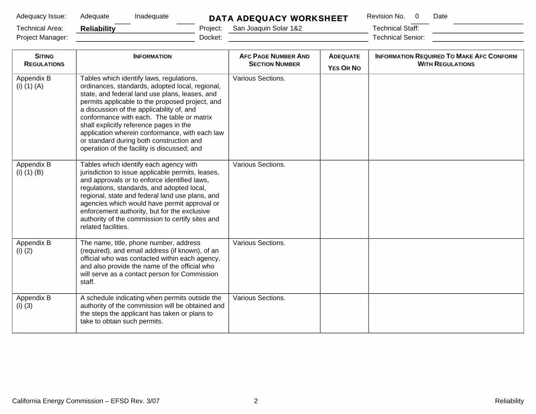
California Energy Commission – EFSD Rev. 3/07 2 Reliability
Adequacy Issue: Adequate Inadequate DATA ADEQUACY WORKSHEET Revision No. 0 Date
Technical Area: Reliability Project: San Joaquin Solar 1&2 Technical Staff: Project Manager: Docket: Technical Senior:
SITING REGULATIONS
INFORMATION AFC PAGE NUMBER AND SECTION NUMBER
ADEQUATE
YES OR NO
INFORMATION REQUIRED TO MAKE AFC CONFORM WITH REGULATIONS
Appendix B (i) (1) (A)
Tables which identify laws, regulations, ordinances, standards, adopted local, regional, state, and federal land use plans, leases, and permits applicable to the proposed project, and a discussion of the applicability of, and conformance with each. The table or matrix shall explicitly reference pages in the application wherein conformance, with each law or standard during both construction and operation of the facility is discussed; and
Various Sections.
Appendix B (i) (1) (B)
Tables which identify each agency with jurisdiction to issue applicable permits, leases, and approvals or to enforce identified laws, regulations, standards, and adopted local, regional, state and federal land use plans, and agencies which would have permit approval or enforcement authority, but for the exclusive authority of the commission to certify sites and related facilities.
Various Sections.
Appendix B (i) (2)
The name, title, phone number, address (required), and email address (if known), of an official who was contacted within each agency, and also provide the name of the official who will serve as a contact person for Commission staff.
Various Sections.
Appendix B (i) (3)
A schedule indicating when permits outside the authority of the commission will be obtained and the steps the applicant has taken or plans to take to obtain such permits.
Various Sections.

California Energy Commission – EFSD Rev. 3/07 1 Project Overview
Adequacy Issue: Adequate Inadequate DATA ADEQUACY WORKSHEET Revision No. 0 Date
Technical Area: Project Overview Project: San Joaquin Solar 1&2 Technical Staff: Docket: Technical Senior:
SITING REGULATIONS
INFORMATION AFC PAGE NUMBER AND SECTION NUMBER
ADEQUATE
YES OR NO
INFORMATION REQUIRED TO MAKE AFC CONFORM WITH REGULATIONS
Cal. Code Regs., tit. 20, § 1704, (a) (3) (A)
Descriptions of all significant assumptions, methodologies, and computational methods used in arriving at conclusions in the document.
Various Sections.
Cal. Code Regs., tit. 20, § 1704, (a) (3) (B)
Descriptions, including methodologies and findings, of all major studies or research efforts undertaken and relied upon to provide information for the document; and a description of ongoing research of significance to the project (including expected completion dates; and
Various Sections.
Cal. Code Regs., tit. 20, § 1704, (a) (3) (C)
A list of all literature relied upon or referenced in the documents, along with brief discussions of the relevance of each such reference
Various Sections
Cal. Code Regs., tit. 20, § 1704, (a) (4)
Each principal subject area covered in a notice or application shall be set forth in a separate chapter or section, each of which shall identify the person or persons responsible for its preparation.
Section 7
Appendix B (a) (1) (A)
A general description of the proposed site and related facilities, including the location of the site or transmission routes, the type, size and capacity of the generating or transmission facilities, fuel characteristics, fuel supply routes and facilities, water supply routes and facilities, pollution control systems, and other general characteristics.
Section 3.2, Section 3.3, Section 3.4
Appendix B (a) (1) (B)
Identification of the location of the proposed site and related facilities by section, township, range, county and assessor’s parcel numbers.
Section 3.2, Section 3.3
Appendix B (a) (1) (C)
A description of and maps depicting the region, the vicinity, and the site and its immediate surroundings.
Section 3.2, Section 3.4.1

California Energy Commission – EFSD Rev. 3/07 2 Project Overview
Adequacy Issue: Adequate Inadequate DATA ADEQUACY WORKSHEET Revision No. 0 Date
Technical Area: Project Overview Project: San Joaquin Solar 1&2 Technical Staff: Docket: Technical Senior:
SITING REGULATIONS
INFORMATION AFC PAGE NUMBER AND SECTION NUMBER
ADEQUATE
YES OR NO
INFORMATION REQUIRED TO MAKE AFC CONFORM WITH REGULATIONS
Appendix B (a) (1) (D)
A full-page color photographic reproduction depicting the visual appearance of the site prior to construction, and a full-page color simulation or artist’s rendering of the site and all project components at the site, after construction.
Section 5.13 Figure 1.2-2
Appendix B (a) (1) (E)
In an appendix to the application, a list of current assessor’s parcel numbers and owners’ names and addresses for all parcels within 500 feet of the proposed transmission line and other linear facilities, and within 1000 feet of the proposed powerplant and related facilities.
Appendix A-1
Appendix B (a) (2)
Project Schedule: Proposed dates of initiation and completion of construction, initial start-up, and full-scale operation of the proposed facilities.
Section 3.6.1
Appendix B (a) (3) (A)
A list of all owners and operators of the site(s), the power plant facilities, and, if applicable, thermal host, the geothermal leasehold, the geothermal resource conveyance lines, and the geothermal re-injection system, and a description of their legal interest in these facilities.
Section 3.1
Appendix B (a) (3) (B)
A list of all owners and operators of the proposed electric transmission facilities.
Section 3.4.5, Section 3.4.5.1
Appendix B (a) (3) (C)
A description of the legal relationship between the applicant and each of the persons or entities specified in subsections (a)(3)(A) and (B).
Section 2
Appendix B (b) (1)
In a section entitled, "Generation Facility Description, Design, and Operation" provide the following information:

California Energy Commission – EFSD Rev. 3/07 3 Project Overview
Adequacy Issue: Adequate Inadequate DATA ADEQUACY WORKSHEET Revision No. 0 Date
Technical Area: Project Overview Project: San Joaquin Solar 1&2 Technical Staff: Docket: Technical Senior:
SITING REGULATIONS
INFORMATION AFC PAGE NUMBER AND SECTION NUMBER
ADEQUATE
YES OR NO
INFORMATION REQUIRED TO MAKE AFC CONFORM WITH REGULATIONS
Appendix B (b) (1) (A)
Maps at a scale of 1:24,000 (1” = 2000’), (or appropriate map scale agreed to by staff) along with an identification of the dedicated leaseholds by section, township, range, county, and county assessor’s parcel number, showing the proposed final locations and layout of the power plant and all related facilities;
Figure 5.9-3
Appendix B (b) (1) (B)
Scale plan and elevation drawings depicting the relative size and location of the power plant and all related facilities to establish the accuracy of the photo simulations required in Sections (a)(1)(D) and (g)(6)(F);
Appendix A-4, Appendix A-5,
Appendix B (b) (1) (C)
A detailed description of the design, construction and operation of the facilities, specifically including the power generation, cooling, water supply and treatment, waste handling and control, pollution control, fuel handling, and safety, emergency and auxiliary systems, and fuel types and fuel use scenarios; and
Section 3
Appendix B (b) (1) (D)
A description of how the site and related facilities were selected and the consideration given to engineering constraints, site geology, environmental impacts, water, waste and fuel constraints, electric transmission constraints, and any other factors considered by the applicant.
Section 3.1 through 3.3
Appendix B (b) (2)
In a section entitled, "Transmission Lines Description, Design, and Operation" provide the following information:
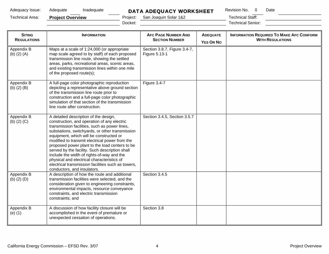
California Energy Commission – EFSD Rev. 3/07 4 Project Overview
Adequacy Issue: Adequate Inadequate DATA ADEQUACY WORKSHEET Revision No. 0 Date
Technical Area: Project Overview Project: San Joaquin Solar 1&2 Technical Staff: Docket: Technical Senior:
SITING REGULATIONS
INFORMATION AFC PAGE NUMBER AND SECTION NUMBER
ADEQUATE
YES OR NO
INFORMATION REQUIRED TO MAKE AFC CONFORM WITH REGULATIONS
Appendix B (b) (2) (A)
Maps at a scale of 1:24,000 (or appropriate map scale agreed to by staff) of each proposed transmission line route, showing the settled areas, parks, recreational areas, scenic areas, and existing transmission lines within one mile of the proposed route(s);
Section 3.8.7, Figure 3.4-7, Figure 5.13-1
Appendix B (b) (2) (B)
A full-page color photographic reproduction depicting a representative above ground section of the transmission line route prior to construction and a full-page color photographic simulation of that section of the transmission line route after construction.
Figure 3.4-7
Appendix B (b) (2) (C)
A detailed description of the design, construction, and operation of any electric transmission facilities, such as power lines, substations, switchyards, or other transmission equipment, which will be constructed or modified to transmit electrical power from the proposed power plant to the load centers to be served by the facility. Such description shall include the width of rights-of-way and the physical and electrical characteristics of electrical transmission facilities such as towers, conductors, and insulators.
Section 3.4.5, Section 3.5.7
Appendix B (b) (2) (D)
A description of how the route and additional transmission facilities were selected, and the consideration given to engineering constraints, environmental impacts, resource conveyance constraints, and electric transmission constraints; and
Section 3.4.5
Appendix B (e) (1)
A discussion of how facility closure will be accomplished in the event of premature or unexpected cessation of operations.
Section 3.8

California Energy Commission – EFSD Rev. 3/07 1 Facility Design
Adequacy Issue: Adequate Inadequate DATA ADEQUACY WORKSHEET Revision No. 0 Date
Technical Area: Facility Design Project: San Joaquin Solar 1&2 Technical Staff: Project Manager: Docket: Technical Senior:
SITING
REGULATIONS INFORMATION AFC PAGE NUMBER AND
SECTION NUMBER ADEQUATE
YES OR NO
INFORMATION REQUIRED TO MAKE AFC CONFORM WITH REGULATIONS
Appendix B (h) (1) (A)
A description of the site conditions and investigations or studies conducted to determine the site conditions used as the basis for developing design criteria. The descriptions shall include, but not be limited to, seismic and other geologic hazards, adverse conditions that could affect the project’s foundation, adverse meteorological and climatic conditions, and flooding hazards, if applicable.
Section 3.2, Section 3.3, Section 3.6.1.4, Section 3.6.1.5
Appendix B (h) (1) (B)
A discussion of any measures proposed to improve adverse site conditions.
Section 3.4.1, Section 3.6.1.5, Section 3.8.3.3, Section 3.8.3.1, Section 3.8.3.4
Appendix B (h) (1) (C)
A description of the proposed foundation types, design criteria (including derivation), analytical techniques, assumptions, loading conditions, and loading combinations to be used in the design of facility structures and major mechanical and electrical equipment
Section 3.4.5.2, Section 3.6.1.4, Section 3.6.1.5
Appendix B (h) (1) (D)
For each of the following facilities and/or systems, provide a description including drawings, dimensions, surface-area requirements, typical operating data, and performance and design criteria for protection from impacts due to adverse site conditions:
Appendix B (h) (1) (D) (i)
The power generation system; Section 3.4.2, Section 3.4.3
Appendix B (h) (1) (D) (ii)
The heat dissipation system; Section 3.4.6, Section 3.4.7
Appendix B (h) (1) (D) (iii)
The cooling water supply system, and, where applicable, pre-plant treatment procedures;
Section 3.4.6, Section 3.4.7
Appendix B (h) (1) (D) (iv)
The atmospheric emission control system; Section 3.4.3.1

California Energy Commission – EFSD Rev. 3/07 2 Facility Design
Adequacy Issue: Adequate Inadequate DATA ADEQUACY WORKSHEET Revision No. 0 Date
Technical Area: Facility Design Project: San Joaquin Solar 1&2 Technical Staff: Project Manager: Docket: Technical Senior:
SITING
REGULATIONS INFORMATION AFC PAGE NUMBER AND
SECTION NUMBER ADEQUATE
YES OR NO
INFORMATION REQUIRED TO MAKE AFC CONFORM WITH REGULATIONS
Appendix B (h) (1) (D) (v)
The waste disposal system and on-site disposal sites;
Section 3.4.6.3, Section 3.4.8.1, Section 3.4.8, Section 3.4.8.2
Appendix B (h) (1) (D) (vi)
The noise emission abatement system; Section 5.12.6
Appendix B (h) (1) (D) (vii)
The geothermal resource conveyance and re-injection lines (if applicable);
N/A
Appendix B (h) (1) (D) (viii)
Switchyards/transformer systems; and Section 3.4.5, Section 3.4.5.2, Section 3.5.7, Section 3.4.5.1, Section 3.4.5.3
Appendix B (h) (1) (D) (ix)
Other significant facilities, structures, or system components proposed by the applicant.
Section 3.4.3, Section 3.4.5., Section 3.4.4
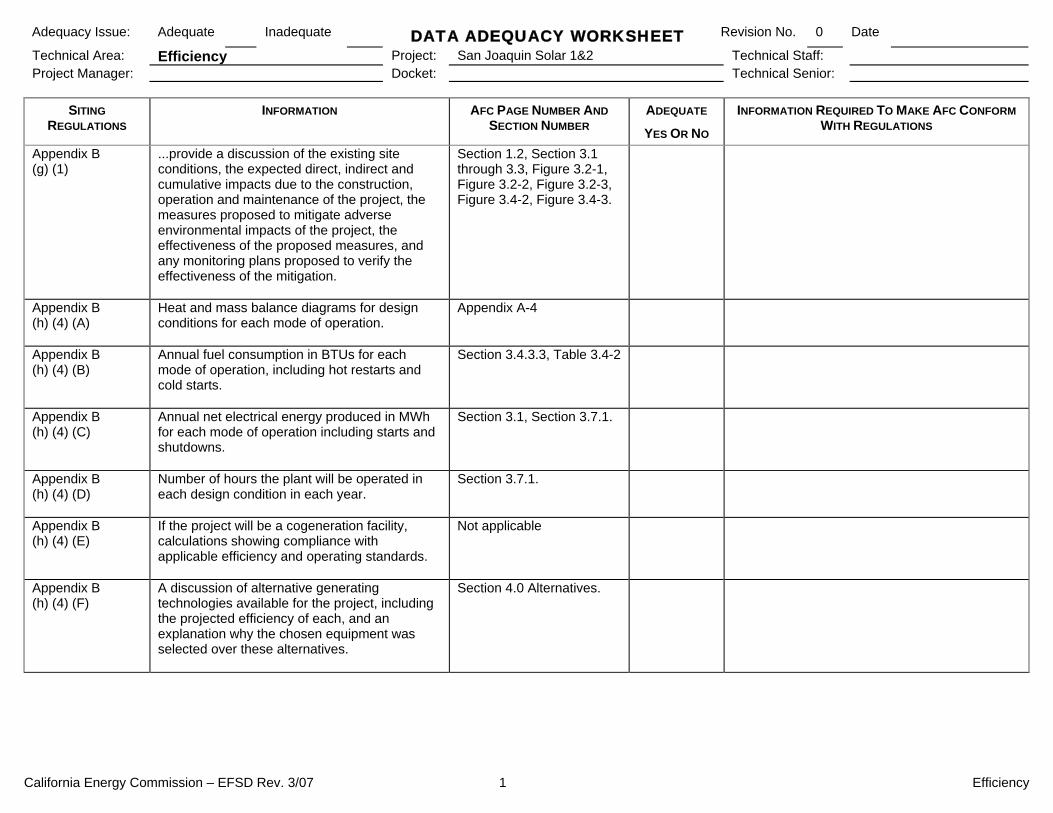
California Energy Commission – EFSD Rev. 3/07 1 Efficiency
Adequacy Issue: Adequate Inadequate DATA ADEQUACY WORKSHEET Revision No. 0 Date
Technical Area: Efficiency Project: San Joaquin Solar 1&2 Technical Staff: Project Manager: Docket: Technical Senior:
SITING REGULATIONS
INFORMATION AFC PAGE NUMBER AND SECTION NUMBER
ADEQUATE
YES OR NO
INFORMATION REQUIRED TO MAKE AFC CONFORM WITH REGULATIONS
Appendix B (g) (1)
...provide a discussion of the existing site conditions, the expected direct, indirect and cumulative impacts due to the construction, operation and maintenance of the project, the measures proposed to mitigate adverse environmental impacts of the project, the effectiveness of the proposed measures, and any monitoring plans proposed to verify the effectiveness of the mitigation.
Section 1.2, Section 3.1 through 3.3, Figure 3.2-1, Figure 3.2-2, Figure 3.2-3, Figure 3.4-2, Figure 3.4-3.
Appendix B (h) (4) (A)
Heat and mass balance diagrams for design conditions for each mode of operation.
Appendix A-4
Appendix B (h) (4) (B)
Annual fuel consumption in BTUs for each mode of operation, including hot restarts and cold starts.
Section 3.4.3.3, Table 3.4-2
Appendix B (h) (4) (C)
Annual net electrical energy produced in MWh for each mode of operation including starts and shutdowns.
Section 3.1, Section 3.7.1.
Appendix B (h) (4) (D)
Number of hours the plant will be operated in each design condition in each year.
Section 3.7.1.
Appendix B (h) (4) (E)
If the project will be a cogeneration facility, calculations showing compliance with applicable efficiency and operating standards.
Not applicable
Appendix B (h) (4) (F)
A discussion of alternative generating technologies available for the project, including the projected efficiency of each, and an explanation why the chosen equipment was selected over these alternatives.
Section 4.0 Alternatives.

California Energy Commission – EFSD Rev. 3/07 2 Efficiency
Adequacy Issue: Adequate Inadequate DATA ADEQUACY WORKSHEET Revision No. 0 Date
Technical Area: Efficiency Project: San Joaquin Solar 1&2 Technical Staff: Project Manager: Docket: Technical Senior:
SITING REGULATIONS
INFORMATION AFC PAGE NUMBER AND SECTION NUMBER
ADEQUATE
YES OR NO
INFORMATION REQUIRED TO MAKE AFC CONFORM WITH REGULATIONS
Appendix B (i) (1) (A)
Tables which identify laws, regulations, ordinances, standards, adopted local, regional, state, and federal land use plans, leases, and permits applicable to the proposed project, and a discussion of the applicability of, and conformance with each. The table or matrix shall explicitly reference pages in the application wherein conformance, with each law or standard during both construction and operation of the facility is discussed; and
Various Sections.
Appendix B (i) (1) (B)
Tables which identify each agency with jurisdiction to issue applicable permits, leases, and approvals or to enforce identified laws, regulations, standards, and adopted local, regional, state and federal land use plans, and agencies which would have permit approval or enforcement authority, but for the exclusive authority of the commission to certify sites and related facilities.
Various Sections.
Appendix B (i) (2)
The name, title, phone number, address (required), and email address (if known), of an official who was contacted within each agency, and also provide the name of the official who will serve as a contact person for Commission staff.
Various Sections.
Appendix B (i) (3)
A schedule indicating when permits outside the authority of the commission will be obtained and the steps the applicant has taken or plans to take to obtain such permits.
Various Sections.

California Energy Commission – EFSD Rev. 3/07 1 Transmission System Engineering
Adequacy Issue: Adequate Inadequate DATA ADEQUACY WORKSHEET Revision No. 0 Date
Technical Area: Transmission System Design Project: San Joaquin Solar 1&2 Technical Staff: Project Manager: Docket: Technical Senior:
SITING REGULATIONS
INFORMATION AFC PAGE NUMBER AND SECTION NUMBER
ADEQUATE
YES OR NO
INFORMATION REQUIRED TO MAKE AFC CONFORM WITH REGULATIONS
Appendix B (h) (2) (A)
A discussion of the need for the additional electric transmission lines, substations, or other equipment, the basis for selecting principal points of junction with the existing electric transmission system, and the capacity and voltage levels of the proposed lines, along with the basis for selection of the capacity and voltage levels.
Section 3.4.5, Section 3.5.7, Section 3.8.7
Appendix B (h) (2) (B)
A discussion of the extent to which the proposed electric transmission facilities have been designed, planned, and routed to meet the transmission requirements created by additional generating facilities planned by the applicant or any other entity.
Section 3.4.5.1
Appendix B (b) (2) (C)
A detailed description of the design, construction, and operation of any electric transmission facilities, such as power lines, substations, switchyards, or other transmission equipment, which will be constructed or modified to transmit electrical power from the proposed power plant to the load centers to be served by the facility. Such description shall include the width of rights of way and the physical and electrical characteristics of electrical transmission facilities such as towers, conductors, and insulators. This description shall include power load flow diagrams which demonstrate conformance or nonconformance with utility reliability and planning criteria at the time the facility is expected to be placed in operation and five years thereafter; and
Section 3.4.5.1, Section 3.5.7, Section 3.8.7
Appendix B (b) (2) (D)
A description of how the route and additional transmission facilities were selected, and the consideration given to engineering constraints, environmental impacts, resource conveyance constraints, and electric transmission constraints.
Section 3.4.5.1

California Energy Commission – EFSD Rev. 3/07 2 Transmission System Engineering
Adequacy Issue: Adequate Inadequate DATA ADEQUACY WORKSHEET Revision No. 0 Date
Technical Area: Transmission System Design Project: San Joaquin Solar 1&2 Technical Staff: Project Manager: Docket: Technical Senior:
SITING REGULATIONS
INFORMATION AFC PAGE NUMBER AND SECTION NUMBER
ADEQUATE
YES OR NO
INFORMATION REQUIRED TO MAKE AFC CONFORM WITH REGULATIONS
Appendix B (b) (2) (E)
A completed System Impact Study or signed System Impact Study Agreement with the California Independent System Operator and proof of payment. When not connecting to the California Independent System Operator controlled grid, provide the executed System Impact Study agreement and proof of payment to the interconnecting utility. If the interconnection and operation of the proposed project will likely impact an transmission system that is not controlled by the interconnecting utility (or California Independent System Operator), provide evidence of a System Impact Study or agreement and proof of payment (when applicable) with/to the impacted transmission owner or provide evidence that there are no system impacts requiring mitigation.
Appendix A-3
Appendix B (i) (1) (A)
Tables which identify laws, regulations, ordinances, standards, adopted local, regional, state, and federal land use plans, leases, and permits applicable to the proposed project, and a discussion of the applicability of, and conformance with each. The table or matrix shall explicitly reference pages in the application wherein conformance, with each law or standard during both construction and operation of the facility is discussed; and
Various Sections
Appendix B (i) (1) (B)
Tables which identify each agency with jurisdiction to issue applicable permits, leases, and approvals or to enforce identified laws, regulations, standards, and adopted local, regional, state and federal land use plans, and agencies which would have permit approval or enforcement authority, but for the exclusive authority of the commission to certify sites and related facilities.
Various Sections

California Energy Commission – EFSD Rev. 3/07 3 Transmission System Engineering
Adequacy Issue: Adequate Inadequate DATA ADEQUACY WORKSHEET Revision No. 0 Date
Technical Area: Transmission System Design Project: San Joaquin Solar 1&2 Technical Staff: Project Manager: Docket: Technical Senior:
SITING REGULATIONS
INFORMATION AFC PAGE NUMBER AND SECTION NUMBER
ADEQUATE
YES OR NO
INFORMATION REQUIRED TO MAKE AFC CONFORM WITH REGULATIONS
Appendix B (i) (2)
The name, title, phone number, address (required), and email address (if known), of an official who was contacted within each agency, and also provide the name of the official who will serve as a contact person for Commission staff.
Various Sections
Appendix B (i) (3)
A schedule indicating when permits outside the authority of the commission will be obtained and the steps the applicant has taken or plans to take to obtain such permits.
Various Sections

California Energy Commission – EFSD Rev. 3/07 4 Transmission System Engineering
This page intentionally left blank

California Energy Commission - EFSD Rev. 3/07 1 Transmission Line Safety and Nuisance
Adequacy Issue: Adequate Inadequate DATA ADEQUACY WORKSHEET Revision No. 0 Date
Technical Area: Trans Line Safety & Nuisance Project: San Joaquin Solar 1&2 Technical Staff: Project Manager: Docket: Technical Senior:
SITING REGULATIONS
INFORMATION AFC PAGE NUMBER AND SECTION NUMBER
ADEQUATE
YES OR NO
INFORMATION REQUIRED TO MAKE AFC CONFORM WITH REGULATIONS
Appendix B (g) (1)
...provide a discussion of the existing site conditions, the expected direct, indirect and cumulative impacts due to the construction, operation and maintenance of the project, the measures proposed to mitigate adverse environmental impacts of the project, the effectiveness of the proposed measures, and any monitoring plans proposed to verify the effectiveness of the mitigation.
Section 3.3
Appendix B (g) (18) (A)
The locations and a description of the existing switchyards and overhead and underground transmission lines that would be affected by the proposed project.
Section 3.4.5.1
Appendix B (g) (18) (B)
An estimate of the existing electric and magnetic fields from the facilities listed in (A) above and the future electric and magnetic fields that would be created by the proposed project, calculated at the property boundary of the site and at the edge of the rights of way for any transmission line. Also provide an estimate of the radio and television interference that could result from the project.
Section 3.8.10, Section 3.8.12.
Appendix B (g) (18) (C)
Specific measures proposed to mitigate identified impacts, including a description of measures proposed to eliminate or reduce radio and television interference, and all measures taken to reduce electric and magnetic field levels.
Section 3.8.10 through 3.8.12.

California Energy Commission - EFSD Rev. 3/07 2 Transmission Line Safety and Nuisance
Adequacy Issue: Adequate Inadequate DATA ADEQUACY WORKSHEET Revision No. 0 Date
Technical Area: Trans Line Safety & Nuisance Project: San Joaquin Solar 1&2 Technical Staff: Project Manager: Docket: Technical Senior:
SITING REGULATIONS
INFORMATION AFC PAGE NUMBER AND SECTION NUMBER
ADEQUATE
YES OR NO
INFORMATION REQUIRED TO MAKE AFC CONFORM WITH REGULATIONS
Appendix B (i) (1) (A)
Tables which identify laws, regulations, ordinances, standards, adopted local, regional, state, and federal land use plans, leases, and permits applicable to the proposed project, and a discussion of the applicability of, and conformance with each. The table or matrix shall explicitly reference pages in the application wherein conformance, with each law or standard during both construction and operation of the facility is discussed; and
Section 3.9, Various Sections.
Appendix B (i) (1) (B)
Tables which identify each agency with jurisdiction to issue applicable permits, leases, and approvals or to enforce identified laws, regulations, standards, and adopted local, regional, state and federal land use plans, and agencies which would have permit approval or enforcement authority, but for the exclusive authority of the commission to certify sites and related facilities.
Various Sections.
Appendix B (i) (2)
The name, title, phone number, address (required), and email address (if known), of an official who was contacted within each agency, and also provide the name of the official who will serve as a contact person for Commission staff.
Various Sections.
Appendix B (i) (3)
A schedule indicating when permits outside the authority of the commission will be obtained and the steps the applicant has taken or plans to take to obtain such permits.
Various Sections.

San Joaquin Solar 1 & 2
Pacific Ocean
Fresno County
Kern County
Monterey County
Tulare County
San Luis Obispo County
Madera CountyMerced County
Santa Barbara County
Ventura County
Kings County
San Benito County
Santa Clara County
Mariposa CountyStanislaus County
Alameda County
Santa Cruz County
Mono County
San Mateo County
San Joaquin County
Los Angeles County
Tuolumne County
§̈¦5
§̈¦880
Path
: G:\g
is\p
roje
cts\
1577
\276
5803
1\al
tern
ativ
e\m
ap_d
ocs\m
xd\p
roj_
desc
\regi
onal
.mxd
, 11
/13/
08,
paul
_mor
eno
SOURCES: ESRI (background).REGIONAL MAP
SAN JOAQUIN SOLAR 1 & 2
CREATED BY CM
PM: AR PROJ. NO: 27658031
DATE: 11-13-08 FIG. NO:3.2-1SCALE: 1" = 25 Miles (1:1,584,000)
12.5 0 12.5 25 Miles
OSCALE CORRECT WHEN PRINTED AT 8.5X11

San Joaquin Solar 1 & 2
Gates Substation
§̈¦5
S La
ssen
Ave
S La
ssen
Ave
Alpine Ave
Alpine Ave
W Jayne Ave
W Tractor Ave
S S
utt e
r Av e
S G
l enn
Av e
W Phelps Ave
S L
ake
Av e
S B
u tte
Ave
S T
r inity
Av e
Modoc Ave
S E
l Dor
ado
Ave
Skyline Rd
S Y
uba
Ave
Sommerville Ln
W Phelps Ave
PROJECT VICINITY MAPSAN JOAQUIN SOLAR 1 & 2
CREATED BY: CM
PM: AR PROJ. NO: 27658031
DATE: 07-30-08 FIG. NO:3.2-2SCALE: 1" = 3000' (1:36,000)
1500 0 1500 3000 Feet
OSCALE CORRECT WHEN PRINTED AT 11X17P
ath:
G:\
gis\
proj
ects
\157
7\27
6580
31\a
ltern
ativ
e\m
ap_d
ocs\
mxd
\pro
j_de
sc\v
icin
ity_m
ap.m
xd,
11/1
3/08
, co
lin_m
attis
on
OVERVIEW MAP
[
§̈¦5
Project Site
Fresno County
KingsCounty
Monterey County
San BenitoCounty
SOURCES:TOPO 24K(various dates);ESRI (roads).
LEGEND
San Joaquin Solar 1 & 2
Gates Substation
Transmission LineNorthern Route
Southern Route

San Joaquin Solar 1 & 2
Gates Substation
§̈¦5
S La
ssen
Ave
S La
ssen
Ave
Alpine Ave
Alpine Ave
W Jayne Ave
W Tractor Ave
S S
utt e
r Av e
S G
l enn
Av e
W Phelps Ave
S L
ake
Av e
S B
u tte
Ave
S T
r inity
Av e
Modoc Ave
S E
l Dor
ado
Ave
Skyline Rd
S Y
uba
Ave
Sommerville Ln
W Phelps Ave
PROJECT LOCATION MAPSAN JOAQUIN SOLAR 1 & 2
CREATED BY: CM
PM: AR PROJ. NO: 27658031
DATE: 07-02-08 FIG. NO:3.2-3SCALE: 1" = 3000' (1:36,000)
1500 0 1500 3000 Feet
OSCALE CORRECT WHEN PRINTED AT 11X17P
ath:
G:\
gis\
proj
ects
\157
7\27
6580
31\a
ltern
ativ
e\m
ap_d
ocs\
mxd
\pro
j_de
sc\lo
catio
n_m
ap.m
xd,
11/1
3/08
, co
lin_m
attis
on
California NAIP aerial imagery is freely distributed by The California Spatial Information Library (CaSIL). CaSIL, the California Resources Agency, and the State of California are 2005 California NAIP Imagery funding partners
OVERVIEW MAP
[
§̈¦5
Project Site
Fresno County
KingsCounty
Monterey County
San BenitoCounty
SOURCES:USDA FSA Aerial Photography Field Office (aerial 2005); CNDDB (Mar. 2008);ESRI (roads).
LEGEND
San Joaquin Solar 1 & 2
Gates Substation

San Joaquin Solar 1 & 2
Gates Substation
§̈¦5
!(33
SITE TOPOGRAPHYSAN JOAQUIN SOLAR 1 & 2
CREATED BY: CM
PM: AR PROJ. NO: 27658031
DATE: 04-29-08 FIG. NO:3.3-1SCALE: 1" = 1 Mile (1:63,360)
0.5 0 0.5 1 Miles
OSCALE CORRECT WHEN PRINTED AT 11X17P
ath:
G:\
gis\
proj
ects
\157
7\27
6580
31\a
ltern
ativ
e\m
ap_d
ocs\
mxd
\pro
j_de
sc\s
ite_t
opog
raph
y.m
xd,
11/1
3/08
, co
lin_m
attis
on
SOURCES:USGS (NED); ESRI (roads).
LEGEND
San Joaquin Solar 1 & 2
Gates Substation
ElevationHigh : 500 meters
Low : 55 meters
OVERVIEW MAP
[
§̈¦5
Project Site
Fresno County
KingsCounty
Monterey County
San BenitoCounty

CREATED BY: CM
PM: AR PROJ. NO: 27658031
DATE: 11-10-08 FIG. NO:
3.4-1NO SCALE
SITE PLANSAN JOAQUIN SOLAR 1 & 2
SOURCE: Ford, Davis and Bacon (drawing 2008)

DATE: 11.14.08 CREATED BY: JW
PROJ. NO: 27658031 PM:AR
FIG. NO: 3.4-2 NO SCALE
AERIAL RENDERING OF SAN JOAQUIN SOLAR 1 & 2

NO SCALE DATE: 11.14.08 CREATED BY: JW
PROJ. NO: 27658031 PM:AR
FIG. NO: 3.4-3
CLOSE-UP RENDERING OF SAN JOAQUIN SOLAR 1 & 2
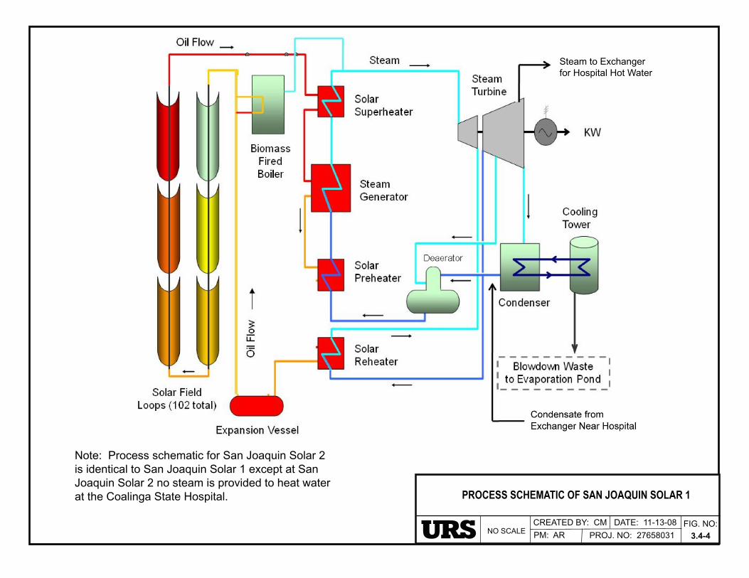
Note: Process schematic for San Joaquin Solar 2 is identical to San Joaquin Solar 1 except at SanJoaquin Solar 2 no steam is provided to heat waterat the Coalinga State Hospital.
PROJ. NO: 27658031FIG. NO:
3.4-4
PROCESS SCHEMATIC OF SAN JOAQUIN SOLAR 1
PM: ARNO SCALECREATED BY: CM DATE: 11-13-08
Steam to Exchangerfor Hospital Hot Water

PROCESS FLOW OF ONE 20 MW BIOMASS UNIT
CREATED BY CM
PM: AR PROJ. NO: 27658031
DATE: 10-30-08 FIG. NO:
3.4-5NO SCALE
SOURCE:Energy Product of Idaho, 2008
Note: Each Solar hybrid plant includes two20 MW biomass units.

SINGLE LINE DIAGRAM FOR THESAN JOAQUIN 1 & 2 SOLAR HYBRID PROJECT
CREATED BY: CM
PM: AR PROJ. NO: 27658031
DATE: 10-31-08 FIG. NO:
3.4-6NO SCALE

San Joaquin Solar 1 & 2
Gates Substation
POTENTIAL TRANSMISSION LINE ROUTESSAN JOAQUIN SOLAR 1 & 2
CREATED BY: CM
PM: AR PROJ. NO: 27658031
DATE: 07-30-08 FIG. NO:3.4-7SCALE: 1" = 3000' (1:36,000)
1500 0 1500 3000 Feet
OSCALE CORRECT WHEN PRINTED AT 11X17P
ath:
G:\
gis\
proj
ects
\157
7\27
6580
31\a
ltern
ativ
e\m
ap_d
ocs\
mxd
\pro
j_de
sc\p
oten
tial_
tline
_rou
tes.
mxd
, 11
/13/
08,
colin
_mat
tison
OVERVIEW MAP
[
§̈¦5
Project Site
Fresno County
KingsCounty
Monterey County
San BenitoCounty
SOURCES:TOPO 24K(various dates);ESRI (roads).
LEGEND
San Joaquin Solar 1 & 2
Gates Substation
Transmission LineNorthern Route
Southern Route
Existing Transmission Lines

CREATED BY: CM
PM: AR PROJ. NO: 27658031
DATE: 11-13-08 FIG. NO:
3.4-8NO SCALE
SINGLE LINE OF AUXILIARY POWER SCHEMES
SAN JOAQUIN SOLAR 1
SOURCE:Ford, Bacon & Davis, 2008
GENERATOR SAN JOAQUIN SOLAR 1 SINGLE LINE
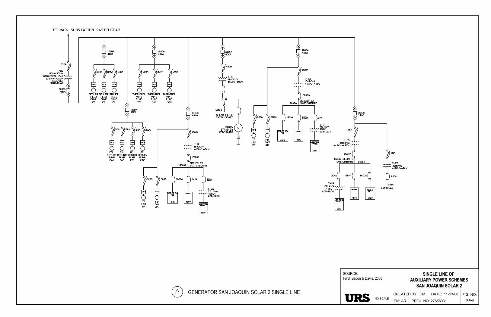
CREATED BY: CM
PM: AR PROJ. NO: 27658031
DATE: 11-13-08 FIG. NO:
3.4-9NO SCALE
SINGLE LINE OF AUXILIARY POWER SCHEMES
SAN JOAQUIN SOLAR 2
SOURCE:Ford, Bacon & Davis, 2008
GENERATOR SAN JOAQUIN SOLAR 2 SINGLE LINE
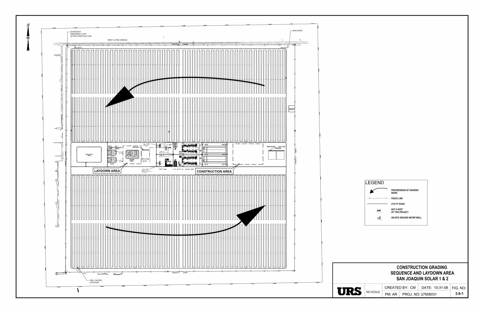
CREATED BY: CM
PM: AR PROJ. NO: 27658031
DATE: 10-31-08 FIG. NO:
3.6-1NO SCALE
CONSTRUCTION GRADING SEQUENCE AND LAYDOWN AREA
SAN JOAQUIN SOLAR 1 & 2
PROGRESSION OF GRADINGWORK
FENCE LINE
UTILITY ROAD
NOT A PARTOF THIS PROJECT
ON-SITE GROUND WATER WELL
LAYDOWN AREA CONSTRUCTION AREA

January February March April May June July August September October November December 1 2 3 4 5 6 7 8 9 10 11 12 13 14 15 16 17 18 19 20 21 22 23
Ho
ur
of
the
Day
24 Solar production only Solar production supplemented by biomass combustion Biomass combustion only
Note: Biomass-based electrical production is subordinate to solar-base electical production. Biomass facilities operate at an annual average of approximately 75% of maximum capacity.
PROJ. NO: 27658031FIG. NO:
3.7-1
PLANNED OPERATION OF THE SOLAR ANDBIOMASS COMPONANTS OF SAN JOAQUIN SOLAR 1 & 2
PM: ARNO SCALECREATED BY: CM DATE: 11-13-08


![ELABORATION OF SOLAR PLANTS WITH STIRLING ENGINE · Stirling parabolic solar system, author’s elaboration [3]. 96 Elaboration of solar plants with stirling engine Technical](https://img.dokumen.tips/doc/110x75/5ece162c76ae9231b56f4a50/elaboration-of-solar-plants-with-stirling-engine-stirling-parabolic-solar-system.jpg)