Embed Size (px)
Citation preview

EM-1
ENGINE MECHANICAL
B ENGINE
CONTENTS
C
D
E
F
G
H
I
J
K
L
M
SECTION
A
EM
Revision: July 2005 2005 Maxima
PRECAUTIONS .......................................................... 3Precautions for Supplemental Restraint System (SRS) “AIR BAG” and “SEAT BELT PRE-TEN-SIONER” .................................................................. 3Precautions for Drain Coolant .................................. 3Precautions for Disconnecting Fuel Piping .............. 3Precautions for Removal and Disassembly ............. 3Precautions for Inspection, Repair and Replace-ment ......................................................................... 3Precautions for Assembly and Installation ............... 3Parts Requiring Angular Tightening ......................... 4Precautions for Liquid Gasket .................................. 4
REMOVAL OF LIQUID GASKET SEALING .......... 4LIQUID GASKET APPLICATION PROCEDURE ..... 4
PREPARATION ........................................................... 6Special Service Tools ............................................... 6Commercial Service Tools ........................................ 8
NOISE, VIBRATION, AND HARSHNESS (NVH) TROUBLESHOOTING .............................................. 10
NVH Troubleshooting — Engine Noise .................. 10Use the Chart Below to Help You Find the Cause of the Symptom. ......................................................11
DRIVE BELTS ........................................................... 12Checking Drive Belts .............................................. 12Tension Adjustment ................................................ 13
GENERATOR AND AIR CONDITIONER COM-PRESSOR BELT ................................................. 14POWER STEERING OIL PUMP BELT ............... 15
Removal and Installation ........................................ 15REMOVAL ........................................................... 15INSTALLATION ................................................... 15
AIR CLEANER AND AIR DUCT ............................... 16Removal and Installation ........................................ 16
REMOVAL ........................................................... 16INSTALLATION ................................................... 17CHANGING AIR CLEANER FILTER ................... 17
INTAKE MANIFOLD COLLECTOR .......................... 18Removal and Installation ........................................ 18
REMOVAL ........................................................... 19INSTALLATION ................................................... 20
EGR VOLUME CONTROL VALVE ........................... 22Removal and Installation ........................................ 22
REMOVAL ........................................................... 23INSTALLATION ................................................... 23
INTAKE MANIFOLD ................................................. 25Removal and Installation ........................................ 25
REMOVAL ........................................................... 25INSPECTION AFTER REMOVAL ....................... 26INSTALLATION ................................................... 26
EXHAUST MANIFOLD AND THREE WAY CATA-LYST .......................................................................... 27
Removal and Installation ........................................ 27REMOVAL ........................................................... 28INSPECTION AFTER REMOVAL ....................... 29INSTALLATION ................................................... 29
OIL PAN AND OIL STRAINER ................................. 31Removal and Installation ........................................ 31
REMOVAL ........................................................... 31INSPECTION AFTER REMOVAL ....................... 34INSTALLATION ................................................... 34INSPECTION AFTER INSTALLATION ................ 36
IGNITION COIL ......................................................... 37Removal and Installation ........................................ 37
REMOVAL ........................................................... 37INSTALLATION ................................................... 37
SPARK PLUG (PLATINUM-TIPPED TYPE) ............. 38Removal and Installation ........................................ 38
REMOVAL ........................................................... 38INSPECTION AFTER REMOVAL ....................... 39INSTALLATION ................................................... 39
FUEL INJECTOR AND FUEL TUBE ........................ 40Removal and Installation ........................................ 40
REMOVAL ........................................................... 40INSTALLATION ................................................... 41INSPECTION AFTER INSTALLATION ................ 41
ROCKER COVER ..................................................... 43Removal and Installation ........................................ 43
REMOVAL ........................................................... 43INSTALLATION ................................................... 44

EM-2Revision: July 2005 2005 Maxima
FRONT TIMING CHAIN CASE ................................. 46Removal and Installation ........................................ 46
REMOVAL ........................................................... 47INSTALLATION .................................................... 53
TIMING CHAIN .......................................................... 58Removal and Installation ........................................ 58
REMOVAL ........................................................... 59INSPECTION AFTER REMOVAL ........................ 70INSTALLATION .................................................... 70
CAMSHAFT ............................................................... 83Removal and Installation ........................................ 83
REMOVAL ........................................................... 84INSPECTION AFTER REMOVAL ........................ 86INSTALLATION .................................................... 88
INSPECTION AFTER INSTALLATION ................... 92INSPECTION OF CAMSHAFT SPROCKET (INT) OIL GROOVE ............................................. 92
Valve Clearance ...................................................... 93CHECKING .......................................................... 93VALVE ADJUSTING ............................................ 95
OIL SEAL .................................................................. 97Removal and Installation of Valve Oil Seal ............. 97
REMOVAL ........................................................... 97INSTALLATION .................................................... 97
Removal and Installation of Front Oil Seal ............. 97REMOVAL ........................................................... 97INSTALLATION .................................................... 99
Removal and Installation of Rear Oil Seal .............. 99REMOVAL ........................................................... 99INSTALLATION .................................................. 100
CYLINDER HEAD ................................................... 101On-Vehicle Service ............................................... 101
CHECKING COMPRESSION PRESSURE ....... 101Removal and Installation ...................................... 102
REMOVAL ......................................................... 102INSPECTION AFTER REMOVAL ...................... 104INSTALLATION .................................................. 104
Disassembly and Assembly .................................. 110DISASSEMBLY ..................................................111
Inspection After Disassembly ............................... 112CYLINDER HEAD DISTORTION ...................... 112VALVE DIMENSIONS ........................................ 112VALVE GUIDE CLEARANCE ............................ 112VALVE GUIDE REPLACEMENT ....................... 113VALVE SEAT CONTACT ................................... 114VALVE SEAT REPLACEMENT ......................... 114VALVE SPRING SQUARENESS ....................... 115VALVE SPRING DIMENSIONS AND VALVE SPRING PRESSURE LOAD ............................. 115ASSEMBLY ....................................................... 115
ENGINE ASSEMBLY .............................................. 117Removal and Installation ...................................... 117
REMOVAL ......................................................... 117INSTALLATION .................................................. 120INSPECTION AFTER INSTALLATION .............. 121
CYLINDER BLOCK ................................................. 122Disassembly and Assembly .................................. 122
DISASSEMBLY ................................................. 123ASSEMBLY ....................................................... 126
How to Select Piston and Bearing ........................133DESCRIPTION ..................................................133HOW TO SELECT A PISTON ...........................134HOW TO SELECT CONNECTING ROD BEAR-INGS ..................................................................135HOW TO SELECT MAIN BEARINGS ................136
Inspection After Disassembly ................................139CRANKSHAFT END PLAY ................................139CONNECTING ROD SIDE CLEARANCE .........139PISTON AND PISTON PIN CLEARANCE .........139PISTON RING SIDE CLEARANCE ...................140PISTON RING END GAP ..................................140CONNECTING ROD BEND AND TORSION .....141CONNECTING ROD BEARING HOUSING DIAMETER (BIG END) ......................................141CONNECTING ROD BUSHING OIL CLEAR-ANCE (SMALL END) .........................................141CYLINDER BLOCK DISTORTION ....................142INNER DIAMETER OF MAIN BEARING HOUS-ING .....................................................................143PISTON-TO-CYLINDER BORE CLEARANCE ..143OUTER DIAMETER OF CRANKSHAFT JOUR-NAL ....................................................................145OUTER DIAMETER OF CRANKSHAFT PIN ....145OUT-OF-ROUND AND TAPER OF CRANK-SHAFT ...............................................................145CRANKSHAFT RUNOUT ..................................145OIL CLEARANCE OF CONNECTING ROD BEARING ...........................................................145OIL CLEARANCE OF MAIN BEARING .............146CRUSH HEIGHT OF MAIN BEARING ..............147CRUSH HEIGHT OF CONNECTING ROD BEARING ...........................................................147OUTER DIAMETER OF MAIN BEARING CAP BOLTS ...............................................................147OUTER DIAMETER OF CONNECTING ROD BOLTS ...............................................................148DRIVE PLATE RUNOUT (A/T) ..........................148FLYWHEEL RUNOUT (M/T) ..............................148OIL JET ..............................................................149OIL JET RELIEF VALVE ....................................149
SERVICE DATA AND SPECIFICATIONS (SDS) ....150Standard and Limit ................................................150
GENERAL SPECIFICATIONS ...........................150DRIVE BELT ......................................................151INTAKE MANIFOLD COLLECTOR, INTAKE MANIFOLD AND EXHAUST MANIFOLD ..........151SPARK PLUG ....................................................151CYLINDER HEAD ..............................................152VALVE ................................................................152CAMSHAFT AND CAMSHAFT BEARING .........156CYLINDER BLOCK ............................................156PISTON, PISTON RING AND PISTON PIN ......157CONNECTING ROD ..........................................158CRANKSHAFT ...................................................159AVAILABLE MAIN BEARING .............................160CONNECTING ROD BEARING .........................160MISCELLANEOUS COMPONENTS ..................161BEARING CLEARANCE ....................................161

PRECAUTIONS
EM-3
C
D
E
F
G
H
I
J
K
L
M
A
EM
Revision: July 2005 2005 Maxima
PRECAUTIONS PFP:00001
Precautions for Supplemental Restraint System (SRS) “AIR BAG” and “SEAT BELT PRE-TENSIONER” EBS00M8F
The Supplemental Restraint System such as “AIR BAG” and “SEAT BELT PRE-TENSIONER”, used alongwith a front seat belt, helps to reduce the risk or severity of injury to the driver and front passenger for certaintypes of collision. Information necessary to service the system safely is included in the SRS and SB section ofthis Service Manual.WARNING:● To avoid rendering the SRS inoperative, which could increase the risk of personal injury or death
in the event of a collision which would result in air bag inflation, all maintenance must be per-formed by an authorized NISSAN/INFINITI dealer.
● Improper maintenance, including incorrect removal and installation of the SRS, can lead to per-sonal injury caused by unintentional activation of the system. For removal of Spiral Cable and AirBag Module, see the SRS section.
● Do not use electrical test equipment on any circuit related to the SRS unless instructed to in thisService Manual. SRS wiring harnesses can be identified by yellow and/or orange harnesses orharness connectors.
Precautions for Drain Coolant EBS00M8G
● Drain coolant when engine is cooled.
Precautions for Disconnecting Fuel Piping EBS00M8H
● Before starting work, make sure no fire or spark producing items are in the work area. ● Release fuel pressure before disassembly.● After disconnecting pipes, plug openings to stop fuel leakage.
Precautions for Removal and Disassembly EBS00M8I
● When instructed to use special service tools, use the specified tools. Always be careful to work safely,avoid forceful or uninstructed operations.
● Exercise maximum care to avoid damage to mating or sliding surfaces.● Cover openings of engine system with tape or the equivalent, if necessary, to seal out foreign materials.● Mark and arrange disassembly parts in an organized way for easy troubleshooting and assembly.● When loosening nuts and bolts, as a basic rule, start with the one furthest outside, then the one diagonally
opposite, and so on. If the order of loosening is specified, do exactly as specified. Power tools may beused where noted in the step.
Precautions for Inspection, Repair and Replacement EBS00M8J
● Before repairing or replacing, thoroughly inspect parts. Inspect new replacement parts in the same way,and replace if necessary.
Precautions for Assembly and Installation EBS00M8K
● Use torque wrench to tighten bolts or nuts to specification.● When tightening nuts and bolts, as a basic rule, equally tighten in several different steps starting with the
ones in center, then ones on inside and outside diagonally in this order. If the order of tightening is speci-fied, do exactly as specified.
● Replace with new gasket, packing, oil seal or O-ring.● Thoroughly wash, clean, and air-blow each part. Carefully check oil or coolant passages for any restriction
and blockage. ● Avoid damaging sliding or mating surfaces. Completely remove foreign materials such as cloth lint or dust.
Before assembly, oil sliding surfaces well. ● Release air within route after draining coolant. ● Before starting engine, apply fuel pressure to fuel lines with turning ignition switch ON (with engine
stopped). Then make sure that there are no leaks at fuel line connections.

EM-4Revision: July 2005
PRECAUTIONS
2005 Maxima
● After repairing, start engine and increase engine speed to check coolant, fuel, oil, and exhaust systemsfor leakage.
Parts Requiring Angular Tightening EBS00M8L
● Use an angle wrench for the final tightening of the following engine parts: – Cylinder head bolts– Main bearing cap bolts– Connecting rod cap nuts– Crankshaft pulley bolt (No angle wrench is required as the bolt flange is provided with notches for angular
tightening)● Do not use a torque value for final tightening. ● The torque value for these parts are for a preliminary step.● Ensure thread and seat surfaces are clean and coated with engine oil.
Precautions for Liquid Gasket EBS00M8M
REMOVAL OF LIQUID GASKET SEALING● After removing the mounting bolts and nuts, separate the mating
surface using Tool and remove the liquid gasket sealing.
CAUTION:Be careful not to damage the mating surfaces.
● In areas where the cutter is difficult to use, use a plastic hammerto lightly tap (1) the cutter where the Silicone RTV Sealant isapplied. Use a plastic hammer to slide the cutter (2) by tappingon the side.
CAUTION:If for some unavoidable reason a tool such as a flat-bladedscrewdriver is used, be careful not to damage the mating surfaces.
LIQUID GASKET APPLICATION PROCEDURE1. Using a scraper, remove the old Silicone RTV Sealant adhering
to the gasket application surface and the mating surface.● Remove the sealant completely from the groove of the gasket
application surface, mounting bolts, and bolt holes.2. Thoroughly clean the gasket application surface and the mating
surface and remove adhering moisture, grease and foreignmaterials.
3. Attach the sealant tube to the tube presser.Use Genuine Silicone RTV Sealant or equivalent. Refer toGI-43, "RECOMMENDED CHEMICAL PRODUCTS ANDSEALANTS" .
4. Apply the sealant using Tool without breaks to the specifiedlocation.
● If there is a groove for the sealant application, apply the seal-ant to the groove.
● As for the bolt holes, normally apply the sealant inside theholes. If specified, it should be applied outside the holes.Make sure to read the text of this manual.
● Within five minutes of the sealant application, install the mat-ing component.
● If the sealant protrudes, wipe it off immediately.● Do not retighten after the installation.
Tool number : KV10111100 (J37228)
PBIC0002E
PBIC0003E
Tool number : WS39930000 ( – )
WBIA0567E

PRECAUTIONS
EM-5
C
D
E
F
G
H
I
J
K
L
M
A
EM
Revision: July 2005 2005 Maxima
● After 30 minutes or more have passed from the installation, fillthe engine with the specified oil and coolant. Refer to MA-9,"RECOMMENDED FLUIDS AND LUBRICANTS" .
CAUTION:Follow all specific instructions in this manual.
SEM159F

EM-6Revision: July 2005
PREPARATION
2005 Maxima
PREPARATION PFP:00002
Special Service Tools EBS00JAF
The actual shapes of Kent-Moore tools may differ from those of special service tools illustrated here.
Tool number(Kent-Moore No.)Tool name
Description
ST0501S000( — )Engine stand assembly1 ST05011000( — )Engine stand2 ST05012000( — )Base
Disassembling and assembling
KV101J0010(J-47242)Engine support table
Engine and transmission assembly removal
KV10106500( — )Engine stand shaft
Disassembling and assembling
KV10117000(J41262)Engine sub-attachment
KV10117000 has been replaced with KV10117001 (KV10117000 is no longer in production, but it is usable).
KV10117001( — )Engine sub-attachment
Installing on the cylinder block
KV10116200(J26336-B)Valve spring compressor1 KV10115900(J26336-20)Attachment2 KV1019230( — )
Disassembling valve mechanismPart (1) is a component of KV10116200 (J26336-B, but Part (2) is not.
NT042
WBIA0658E
NT028
NT373
NT372
PBIC1650E

PREPARATION
EM-7
C
D
E
F
G
H
I
J
K
L
M
A
EM
Revision: July 2005 2005 Maxima
KV10107902(J38959)Valve oil seal puller
Removing valve oil seal
(J39386)Valve oil seal drift
Installing valve oil seal
EM03470000(J8037)Piston ring compressor
Installing piston assembly into cylinder bore
ST16610001(J23907)Pilot bushing puller
Removing crankshaft pilot bushing
KV10111100(J37228)Seal cutter
Removing steel oil pan and rear timing chain case
KV991J0120(J-47128)Seal installer
Installing rear main seal
WS39930000( — )Tube presser
Pressing the tube of liquid gasket
Tool number(Kent-Moore No.)Tool name
Description
S-NT011
NT024
NT044
NT045
NT046
LBIA0452E
NT052

EM-8Revision: July 2005
PREPARATION
2005 Maxima
Commercial Service Tools EBS00JAG
KV10112100(BT8653-A)Angle wrench
Tightening bolts for bearing cap, cylinder head, etc.
KV991J0050(J-44626)Air fuel sensor Socket
Loosening or tightening air fuel ratio A/F sen-sora: 22 mm (0.87 in)
KV10114400(J38365)Heated oxygen sensor wrench
Loosening or tightening rear heated oxygen sensora: 22 mm (0.87 in)
KV10117700(J44716)Ring gear stopper
Removing and installing crankshaft pulley
Tool number(Kent-Moore No.)Tool name
Description
NT014
LBIA0444E
NT636
NT822
(Kent-Moore No.)Tool name
Description
(BT3373-F)Belt tension gauge
Checking drive belt tension
(J24239-01)Cylinder head bolt wrench
Loosening and tightening cylinder head bolta: 13 (0.51) dia.b: 12 (0.47)c: 10 (0.39)Unit: mm (in)
Power tool Loosening bolts and nuts
AMA126
NT583
PBIC0190E

PREPARATION
EM-9
C
D
E
F
G
H
I
J
K
L
M
A
EM
Revision: July 2005 2005 Maxima
Spark plug wrench Removing and installing spark plug
Valve seat cutter set Finishing valve seat dimensions
Piston ring expander Removing and installing piston ring
Valve guide drift Removing and installing valve guideIntake & Exhaust:a = 9.5 mm (0.374 in) dia.b = 5.5 mm (0.217 in) dia.
Valve guide reamer Reaming valve guide 1 or hole for oversize valve guide 2Intake & Exhaust:d1 = 6.0 mm (0.236 in) dia.d2 = 10.2 mm (0.402 in) dia.
(J-43897-18)(J-43897-12)Oxygen sensor thread cleaner
Reconditioning the exhaust system threads before installing a new oxygen sensor (Use with anti-seize lubricant shown below.)a = J-43897-18 (18 mm dia.) for zirconia ox-ygen sensorb = J-43897-12 (12 mm dia.) for titania oxy-gen sensor
Anti-seize lubricant (Permatex 133AR or equivalent meeting MIL specifica-tion MIL-A-907)
Lubricating oxygen sensor thread cleaning tool when reconditioning exhaust system threads
(Kent-Moore No.)Tool name
Description
NT047
NT048
NT030
NT015
NT016
AEM488
AEM489

EM-10Revision: July 2005
NOISE, VIBRATION, AND HARSHNESS (NVH) TROUBLESHOOTING
2005 Maxima
NOISE, VIBRATION, AND HARSHNESS (NVH) TROUBLESHOOTING PFP:00003
NVH Troubleshooting — Engine Noise EBS00JAH
SEM706G

NOISE, VIBRATION, AND HARSHNESS (NVH) TROUBLESHOOTING
EM-11
C
D
E
F
G
H
I
J
K
L
M
A
EM
Revision: July 2005 2005 Maxima
Use the Chart Below to Help You Find the Cause of the Symptom. EBS00JAI
1. Locate the area where noise occurs.2. Confirm the type of noise.3. Specify the operating condition of engine.4. Check specified noise source. Repair or replace the identified part as necessary.
A: Closely related B: Related C: Sometimes related —: Not related
Location of noise
Type of noise
Operating condition of engine
Source of noise
Check itemRefer-
ence pageBefore warm-
up
After warm-
up
When start-ing
When idling
When racing
While driving
Top of engineRocker coverCylinder head
Ticking or clicking
C A — A B —Tappet noise
Valve clearance EM-93
Rattle C A — A B CCamshaft bearing noise
Camshaft journal clear-anceCamshaft runout
EM-83
Crank-shaft pul-leyCylinder block (Side of engine)Oil pan
Slap or knock
— A — B B —Piston pin noise
Piston and piston pin clearanceConnecting rod bush-ing clearance
EM-101
Slap or rap
A — — B B APiston slap noise
Piston-to-bore clear-ancePiston ring side clear-ancePiston ring end gapConnecting rod bend and torsion
EM-122
Knock A B C B B B
Connect-ing rod bearing noise
Connecting rod bush-ing clearance (Small end)Connecting rod bear-ing clearance (Big end)
EM-122
Knock A B — A B CMain bearing noise
Main bearing oil clear-anceCrankshaft runout
EM-122
Front of engineTiming chain cover
Tapping or ticking
A A — B B B
Timing chain and chain ten-sioner noise
Timing chain cracks and wearTiming chain tensioner operation
EM-58
Front of engine
Squeak-ing or fizz-ing
A B — B — C
Drive belts (Sticking or slip-ping)
Drive belts deflection
EM-12
Creaking A B A B A BDrive belts (Slipping)
Idler pulley bearing operation
SquallCreak
A B — B A BWater pump noise
Water pump operation CO-19

EM-12Revision: July 2005
DRIVE BELTS
2005 Maxima
DRIVE BELTS PFP:02117
Checking Drive Belts EBS00JAJ
WARNING:Be sure to perform when the engine is not running.1. Inspect belt for cracks, fraying, wear or oil adhesion. If necessary, replace with a new one.2. Inspect drive belt deflections by applying 98 N (10kg, 22lb) on
the belt midway between pulleys as shown.3. Measure the belt tension using Tool at the locations shown.
NOTE:● Inspect drive belt deflection or tension when engine is cold.● Adjust if belt deflections exceed the limit or if belt tension is
not within specifications.CAUTION:● When checking belt deflection or tension immediately
after installation, first adjust it to the specification value.Then, after turning the crankshaft two turns or more, readjust to the specified value to avoidvariation in deflection between pulleys.
● Tighten idler pulley lock nut by hand and measure deflec-tion or tension without looseness.
Tool number : BT3373-F
WBIA0325E
PBIC1162E

DRIVE BELTS
EM-13
C
D
E
F
G
H
I
J
K
L
M
A
EM
Revision: July 2005 2005 Maxima
Belt Deflection and Tension
*: If belt tension gauge cannot be installed at check points shown, check drive belt tension at different location on the belt.
Tension Adjustment EBS00JAK
CAUTION:● When belt is replace with a new one, adjust it to value for "New belt" to accommodate for insuffi-
cient adaptability with pulley grooves.● When deflection or tension of belt being used exceeds "Used belt limit" adjust it to value for "Used
belt".● When checking belt deflection or tension immediately after installation, first adjust it to the speci-
fication value. Then, after turning the crankshaft two turns or more, readjust to the specified valueto avoid variation in deflection between pulleys.
Deflection adjustment Unit: mm (in) Tension adjustment* Unit: N (kg, lb)
Used beltNew belt
Used beltNew belt
Limit After adjustment Limit After adjustment
Generator and air conditioning compressor
7 (0.28) 4.2 - 4.6 (0.17 - 0.18)
3.7 - 4.1 (0.15 - 0.16)
294 (30, 66)730 - 818
(74.5 - 83.5,164 - 184)
838 - 926(85.5 - 94.5,188 - 208)
Power steering pump
11 (0.43) 7.3 - 8.0 (0.29 - 0.30)
6.5 - 7.2 (0.26 - 0.28)
196 (20, 44)495 - 583
(50.5 - 59.5,111 - 131)
603 - 691(61.5 - 70.5,
135.6 - 155.4)
Applied pushing force
98N (10kg, 22lb) —
LLIA0060E
Portion Belt tightening method for adjustment
Power steering oil pump belt Adjusting bolt on idler pulley
Generator and air conditioner compressor belt Adjusting bolt on idler pulley

EM-14Revision: July 2005
DRIVE BELTS
2005 Maxima
● When installing belt, make sure that it is correctly engaged with pulley groove.● Keep oil and water away from belt.● Do not twist or bend belt excessively.
GENERATOR AND AIR CONDITIONER COMPRESSOR BELT1. Remove engine undercover.2. Loosen idler pulley lock nut (A) and adjust by turning adjusting
bolt (B).● For specified belt tension, refer to MA-11, "CHECKING
DRIVE BELTS" .3. Tighten lock nut (A) refer to EM-12, "Checking Drive Belts" .4. Tighten adjusting bolt (B) refer to EM-12, "Checking Drive Belts"
.
WBIA0324E

DRIVE BELTS
EM-15
C
D
E
F
G
H
I
J
K
L
M
A
EM
Revision: July 2005 2005 Maxima
POWER STEERING OIL PUMP BELT1. Remove engine undercover.2. Loosen adjusting bolt (C).3. Loosen power steering oil pump bolt (D).
NOTE:Bolt head (D) is at the engine rear side.
4. Adjust by turning the adjusting bolt (E).● For specified belt tension, refer to MA-11, "CHECKING
DRIVE BELTS" .NOTE:Adjusting bolt (E) is loosened with counterclockwise rotation.
5. Tighten adjusting bolt (C) refer to EM-12, "Checking Drive Belts".
6. Tighten power steering oil pump bolt (D) refer toEM-12, "Check-ing Drive Belts" .
Removal and Installation EBS00JAL
REMOVAL1. Remove engine undercover.2. Fully loosen each belt. Refer to MA-13, "Power steering oil pump belt" . Remove generator and air condi-
tioner compressor belt and then power steering oil pump belt.CAUTION:Grease is applied to idler pulley adjusting bolt. Be careful to keep grease away from the belts.
INSTALLATION1. Installation is in the reverse order of removal.
CAUTION:● Make sure belts are correctly engaged with the pulley groove.● Clean off any for oil and coolant on belts and each pulley groove.
2. Adjust belt tension. Refer to MA-13, "Power steering oil pump belt" .
WBIA0324E

EM-16Revision: July 2005
AIR CLEANER AND AIR DUCT
2005 Maxima
AIR CLEANER AND AIR DUCT PFP:16500
Removal and Installation EBS00JAM
REMOVAL1. Remove the grille top cover.2. Remove the fresh air duct.3. Disconnect the harness connector from the mass air flow sensor.4. Disconnect the tube clamp at the electric throttle control actuator.5. Remove air cleaner to electric throttle control actuator tube, air cleaner case (upper) with the mass air flow
sensor attached.6. Remove mass air flow sensor from air cleaner case (upper), as necessary.
CAUTION:Handle mass air flow sensor with care.● Do not shock it.● Do not disassemble it.● Do not touch its sensor.
7. Remove the air cleaner case (lower).8. Remove resonator in the fender, lifting left fender protector, as necessary.
LBIA0335E
1. Air cleaner to electric throttle control actuator tube
2. Mass air flow sensor 3. Air cleaner case (upper)
4. Air cleaner filter 5. Air cleaner case (lower) 6. Air cleaner case bracket
7. Grommet 8. Resonator (in fender) 9. Fresh air duct
10. PCV hose

AIR CLEANER AND AIR DUCT
EM-17
C
D
E
F
G
H
I
J
K
L
M
A
EM
Revision: July 2005 2005 Maxima
INSTALLATIONInstallation is in the reverse order of removal.
CHANGING AIR CLEANER FILTER1. Disconnect the tube clamp at the electric throttle control actuator and mass air flow sensor.2. Separate the mass air flow sensor from the air cleaner to electric throttle control actuator tube.3. Unhook the air cleaner case side clips and remove the air cleaner case (upper).4. Remove the air cleaner filter.5. Install a new air cleaner filter.6. Installation is in the reverse order of removal.

EM-18Revision: July 2005
INTAKE MANIFOLD COLLECTOR
2005 Maxima
INTAKE MANIFOLD COLLECTOR PFP:14010
Removal and Installation EBS00JAN
WBIA0501E

INTAKE MANIFOLD COLLECTOR
EM-19
C
D
E
F
G
H
I
J
K
L
M
A
EM
Revision: July 2005 2005 Maxima
REMOVALWARNING:● To avoid the danger of being scalded, never drain the coolant when the engine is hot.● The gasket for intake manifold collector (upper) is secured together with intake manifold collector
(lower) bolt. Thus, when replacing only the upper gasket the lower gasket must also be replaced.1. Remove the cowl top. Refer to EI-19, "Removal and Installation" .2. Remove the windshield wiper assembly. Refer to WW-23, "Removal and Installation of Wiper Motor and
Linkage" .3. Remove the engine cover using power tool.4. Remove air cleaner case lid and mass air flow sensor, and air
intake tube as an assembly.Refer to EM-16, "Removal and Installation" .
5. Partially drain the coolant when the engine is cool. Refer to MA-14, "DRAINING ENGINE COOLANT" .
6. Disconnect the following:● Power brake booster vacuum hose● Coolant hoses from the intake manifold collector● Swirl control vacuum lines to power valve and intake manifold
collector upper● Fuel injector electrical connectors● PCV hose● Electric throttle control actuator electrical connector● EVAP canister purge hose● EGR temperature sensor electrical connectorCAUTION:● Cover any engine openings to avoid the entry of any for-
eign material.7. Remove the EGR tube (to lower intake manifold collector) nuts.8. Disconnect the power steering hose bracket from the rear of the
intake manifold collector.9. Remove the EVAP canister purge volume solenoid valve bracket bolt. Position the valve aside.10. Remove the VIAS control solenoid valve bracket bolt. Position the valve aside.11. Remove the vacuum tank.12. Remove the intake manifold collector support bracket from the back of the intake manifold collector using
power tool.
1. Electric throttle control actuator 2. Intake manifold collector (upper) 3. EVAP canister purge volume con-trol solenoid valve
4. Intake manifold collector (lower) 5. Power valve 6. VIAS control solenoid valve
7. Vacuum tank 8. Service port 9. Fuel hose
10. Gasket 11. EGR temperature sensor 12. EGR tube (to lower intake manifold collector)
13. EGR volume control valve 14. EGR tube (to exhaust manifold) 15. EGR volume control valve bracket
16. Intake manifold collector (lower) support bracket
WBIA0326E

EM-20Revision: July 2005
INTAKE MANIFOLD COLLECTOR
2005 Maxima
13. Loosen the intake manifold collector bolts in the order shownusing power tool, and remove the intake manifold collector andgasket.
14. If necessary, remove the electric throttle control actuator bolts inthe order shown and remove the electric throttle control actua-tor.CAUTION:● Handle carefully to avoid any shock to the electric throt-
tle control actuator.● Do not disassemble.
15. If necessary, remove the intake manifold collector (upper) boltsin the order shown, using power tool and remove the intakemanifold collector.CAUTION:Handle carefully to avoid any shock to the electric throttlecontrol actuator, if installed.
16. If necessary, remove power valve bolts in the order shown andremove the power valve.
17. If necessary remove the following components:● Vacuum tank● VIAS control solenoid valve● EVAP canister purge volume control solenoid valve
INSTALLATIONInstallation is in the reverse order of removal, paying attention to the following.NOTE:After installation, it is necessary to re-calibrate the electric throttle control actuator as follows:1. Perform the "Throttle Valve Closed Position Learning" when harness connector of the electric throttle con-
trol actuator is disconnected. Refer to EC-90, "Throttle Valve Closed Position Learning" .2. Perform the "Idle Air Volume Learning" when the electric throttle control actuator is replaced. Refer to EC-
91, "Idle Air Volume Learning" .
WBIA0285E
SEM711G
SEM712G
SEM714G

INTAKE MANIFOLD COLLECTOR
EM-21
C
D
E
F
G
H
I
J
K
L
M
A
EM
Revision: July 2005 2005 Maxima
● If necessary, install power valve bolts in the order shown refer toEM-18, "Removal and Installation" .
● If necessary, tighten the intake manifold collector pipe bolts inthe order shown refer to EM-18, "Removal and Installation" .
● If necessary, install the electric throttle control actuator bolts inthe order shown. Install gasket with three protrusions facingdown refer to EM-18, "Removal and Installation" .
● Install the intake manifold collector bolts in the order shown referto EM-18, "Removal and Installation" .
SEM714G
SEM712G
SEM711G
SEM713G

EM-22Revision: July 2005
EGR VOLUME CONTROL VALVE
2005 Maxima
EGR VOLUME CONTROL VALVE PFP:14710
Removal and Installation EBS00JAO
LBIA0347E
1. Gasket 2. EGR temperature sensor 3. EGR tube (to lower intake manifold collector)
4. EGR volume control valve 5. EGR tube (to exhaust manifold) 6. EGR volume control valve bracket
7. Coolant lines
EGR VOLUME CONTROL VALVE
EM-23
C
D
E
F
G
H
I
J
K
L
M
A
EM
Revision: July 2005 2005 Maxima
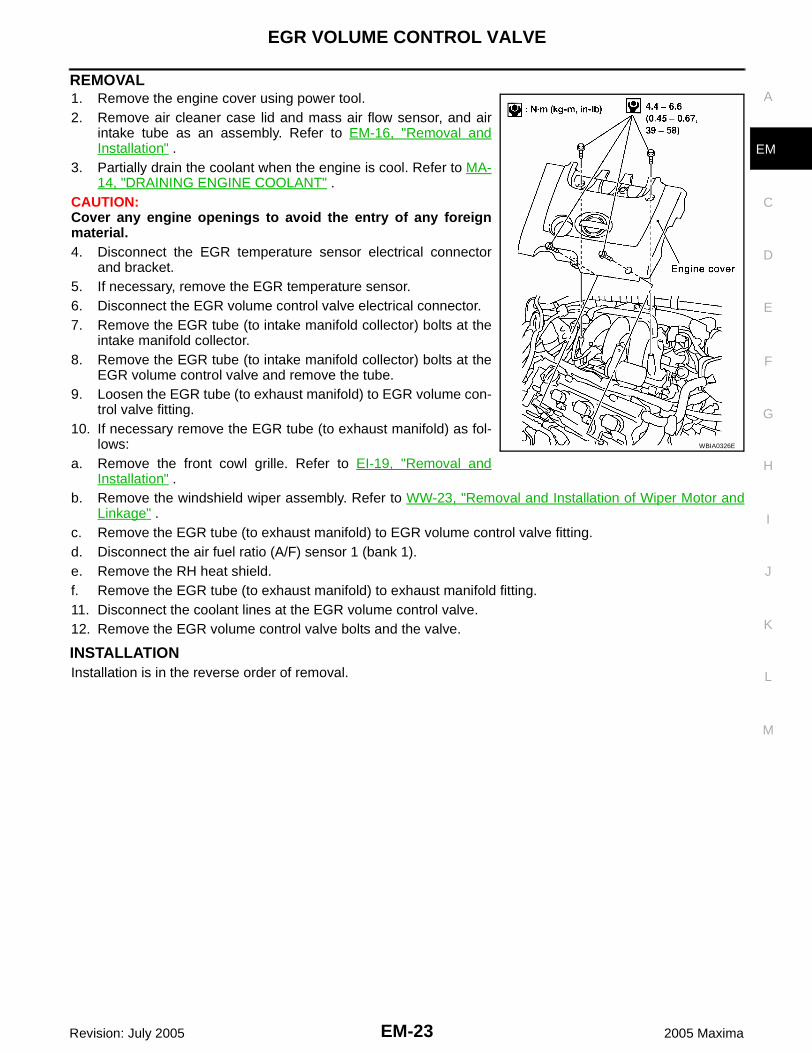
REMOVAL1. Remove the engine cover using power tool.2. Remove air cleaner case lid and mass air flow sensor, and air
intake tube as an assembly. Refer to EM-16, "Removal andInstallation" .
3. Partially drain the coolant when the engine is cool. Refer to MA-14, "DRAINING ENGINE COOLANT" .
CAUTION:Cover any engine openings to avoid the entry of any foreignmaterial.4. Disconnect the EGR temperature sensor electrical connector
and bracket.5. If necessary, remove the EGR temperature sensor.6. Disconnect the EGR volume control valve electrical connector.7. Remove the EGR tube (to intake manifold collector) bolts at the
intake manifold collector.8. Remove the EGR tube (to intake manifold collector) bolts at the
EGR volume control valve and remove the tube.9. Loosen the EGR tube (to exhaust manifold) to EGR volume con-
trol valve fitting.10. If necessary remove the EGR tube (to exhaust manifold) as fol-
lows:a. Remove the front cowl grille. Refer to EI-19, "Removal and
Installation" .b. Remove the windshield wiper assembly. Refer to WW-23, "Removal and Installation of Wiper Motor and
Linkage" .c. Remove the EGR tube (to exhaust manifold) to EGR volume control valve fitting.d. Disconnect the air fuel ratio (A/F) sensor 1 (bank 1). e. Remove the RH heat shield.f. Remove the EGR tube (to exhaust manifold) to exhaust manifold fitting.11. Disconnect the coolant lines at the EGR volume control valve.12. Remove the EGR volume control valve bolts and the valve.
INSTALLATIONInstallation is in the reverse order of removal.
WBIA0326E

EM-24Revision: July 2005
EGR VOLUME CONTROL VALVE
2005 Maxima
● Install the RH heat shield bolts.
RH heat shield bolts
: 5.1 - 6.5 N·m (0.52 - 0.66 kg-m, 46 - 57 in-lb)
LBIA0346E

INTAKE MANIFOLD
EM-25
C
D
E
F
G
H
I
J
K
L
M
A
EM
Revision: July 2005 2005 Maxima
INTAKE MANIFOLD PFP:14003
Removal and Installation EBS00JAP
REMOVAL1. Release the fuel pressure. Refer to EC-93, "FUEL PRESSURE RELEASE" .2. Remove the intake manifold collector. Refer to EM-18, "Removal and Installation" .3. Remove the fuel rail with the fuel injectors. Refer to EM-40, "Removal and Installation" .
4. Loosen the intake manifold nuts and bolts in the order shownusing power tool, and remove the intake manifold.
PBIC1169E
1. Intake manifold 2. Gasket
WBIA0043E

EM-26Revision: July 2005
INTAKE MANIFOLD
2005 Maxima
INSPECTION AFTER REMOVALSurface DistortionUsing straightedge and feeler gauge, inspect the surface distortion of both the intake manifold and the intakemanifold collector.
INSTALLATIONInstallation is in the reverse order of removal. ● If necessary, install the stud bolts.
● Install intake manifold bolts in three steps in the order shown.
Limit : 0.1 mm (0.004 in)
WBIA0052E
PBIC0870E
Stud bolts : 9.8 - 11.8 N·m (1.0 - 1.2 kg-m, 87 - 104 in-lb)
Step 1 : 4.9 - 9.8 N·m (0.5 - 0.99 kg-m, 44 - 86 in-lb)Step 2 : 26.5 - 31.4 N·m (2.7 - 3.2 kg-m, 20 - 23 ft-lb)Step 3 : 26.5 - 31.4 N·m (2.7 - 3.2 kg-m, 20 - 23 ft-lb)
SEM950F

EXHAUST MANIFOLD AND THREE WAY CATALYST
EM-27
C
D
E
F
G
H
I
J
K
L
M
A
EM
Revision: July 2005 2005 Maxima
EXHAUST MANIFOLD AND THREE WAY CATALYST PFP:14004
Removal and Installation EBS00JAQ
WBIA0267E
1. Exhaust manifold (RH bank) 2. Exhaust manifold (LH bank) 3. Air fuel ratio (A/F) sensor 1 (bank 2)
4. Three way catalyst (manifold) (bank 2)
5. Three way catalyst (manifold) (bank 1)
6. Air fuel ratio (A/F) sensor 1 (bank 1)
7. Heated oxygen sensor 2 (front) (bank 1)
8. Heated oxygen sensor 2 (front) (bank 2)

EM-28Revision: July 2005
EXHAUST MANIFOLD AND THREE WAY CATALYST
2005 Maxima
REMOVALWARNING:● Perform the work when the exhaust and cooling system have completely cooled down.● When removing the front and rear engine mounting through bolts and nuts, lift the engine up
slightly for safety. For engine slingers, refer to EM-117, "REMOVAL" .1. Remove the front wheel and tires using power tool.2. Remove the engine undercover.3. Remove the inner wheel well splash shields.4. Remove the radiator and cooling fan assembly. Refer to CO-12, "REMOVAL" .5. Remove the front exhaust tube. Refer to EX-3, "Removal and Installation" .6. Remove the front suspension member. Refer to FSU-15, "Removal and Installation" .7. Remove the RH and LH three way catalyst support bolts in the
order shown.
8. Remove heated oxygen sensor 2 (bank 1), heated oxygen sensor 2 (bank 2), air fuel ratio (A/F) sensor 1(bank 1) and air fuel ratio (A/F) sensor 1 (bank 2).
a. Remove harness connector of each sensor, and disconnect the harness from the bracket and middleclamp.
b. Remove both heated oxygen sensors and air fuel ratio (A/F) sensors using Tool.
CAUTION:● Be careful not to damage heated oxygen sensors or air fuel ratio (A/F) sensors.● Discard any heated oxygen sensor which has been dropped from a height of more than 0.5 m
(19.7 in) onto a hard surface such as a concrete floor; replace with a new sensor.9. Remove exhaust manifold and three way catalyst heat shields with power tool.10. Remove the three way catalyst (manifold) (bank 1) and three way catalyst (manifold) (bank 2) by loosen-
ing the bolts first and then removing the nuts and through bolts.11. Remove the exhaust manifolds. Loosen the exhaust manifold
nuts in the order shown.
PBIC1174E
Tool numbers : KV10114400 (J-38365): KV991J0050 (J-44626)
WBIA0288E

EXHAUST MANIFOLD AND THREE WAY CATALYST
EM-29
C
D
E
F
G
H
I
J
K
L
M
A
EM
Revision: July 2005 2005 Maxima
INSPECTION AFTER REMOVALSurface Distortion● Use a reliable straightedge and feeler gauge to check the flat-
ness of the exhaust manifold mating surfaces.
INSTALLATIONInstallation is in the reverse order of removal.● Install the exhaust manifold nuts in the order shown.
CAUTION:● When using the heated oxygen sensor wrench, tighten to
the middle of specified torque range, because the lengthof the Tool may increase the actual tightness. Do nottighten to the maximum specified torque range.
● Before installing a heated oxygen sensor or air fuel ratio(A/F) sensor, clean the exhaust manifold threads using the oxygen sensor thread cleaner tool,and apply anti-seize lubricant.
● Do not over-tighten the air fuel ratio (A/F) sensor orheated oxygen sensors. Doing so may cause damage.
WBIA0289E
Limit : 0.3 mm (0.012 in)
PBIC1173E
Exhaust manifold nuts
: 28.4 - 33.3 N·m (2.9 - 3.3 kg-m, 21 - 24 lb-ft)
Tool numbers : KV10114400 (J-38365): KV991J0050 (J-44626)
Tool numbers : J-43897-18: J-43897-12
WBIA0277E
WBIA0278E

EM-30Revision: July 2005
EXHAUST MANIFOLD AND THREE WAY CATALYST
2005 Maxima
● Install the RH and LH three way catalyst support bolts in theorder shown.
● Install the exhaust manifold heat shield bolts.
● Install the three way catalyst heat shield bolts.
Three way catalyst support bolts
: 19 - 28 N·m (2.0 - 2.5 kg-m, 14 - 18 ft-lb)
PBIC1174E
Exhaust manifold heat shield bolts
: 5.1 - 6.5 N·m (0.52 - 0.66 kg-m, 46 - 57 in-lb)
Three way catalyst heat shield bolts
: 6.7 - 9.8 N·m (0.69 - 0.99 kg-m, 60 - 86 in-lb)
LBIA0346E

OIL PAN AND OIL STRAINER
EM-31
C
D
E
F
G
H
I
J
K
L
M
A
EM
Revision: July 2005 2005 Maxima
OIL PAN AND OIL STRAINER PFP:11110
Removal and Installation EBS00JAR
REMOVALWARNING:● You should not remove the oil pan until the exhaust system and cooling system have completely
cooled off.● When removing the front and rear engine mounting through bolts and nuts, lift the engine up
slightly for safety. For engine slingers, refer to step 37 in EM-117, "REMOVAL" .CAUTION:When removing the upper oil pan from the engine, first remove the crankshaft position sensor (POS).Be careful not to damage sensor edges or signal plate teeth.1. Remove the front RH wheel and tire using power tool. Refer to WT-4, "WHEEL AND TIRE ASSEMBLY" .2. Disconnect the battery negative terminal.3. Remove the oil dipstick.4. Drain the engine coolant. Refer to MA-14, "DRAINING ENGINE COOLANT" .
WBIA0274E
1. Gasket 2. Upper oil pan 3. O-ring
4. Oil pressure switch 5. Relief valve 6. Oil cooler
7. Oil cooler connection 8. Oil filter 9. Gasket
10. Oil strainer 11. Gasket 12. Drain plug
13. Lower oil pan 14. Rear plate cover 15.Heated oxygen sensor (bank 2) har-ness clamp
16.Crankshaft position sensor (POS) (4 A/T & M/T)
17.Crankshaft position sensor (POS) (5 A/T)
18.Crankshaft position sensor (POS) (5 A/T) shield

EM-32Revision: July 2005
OIL PAN AND OIL STRAINER
2005 Maxima
5. Remove the engine undercover.6. Remove the RH inner fender splash shield.7. Remove the A/C drive belt. Refer to EM-15, "REMOVAL" .8. Remove the front exhaust tube. Refer to EX-3, "Removal and Installation" .9. Remove coolant pipe bolts.10. Remove the A/C compressor with piping attached, and position it out of the way securely with wire.
CAUTION:Do not pull on or crimp the A/C lines and hoses.
11. Disconnect the coolant lines from the engine oil cooler and plug them to prevent coolant loss.12. Remove the oil filter and engine oil cooler from the upper oil pan.13. Remove the oil pressure switch, and the crankshaft position sensor (POS) from the upper oil pan.14. Remove the front drive shafts. Refer to FAX-11, "Removal and Installation" .15. Remove the front suspension member. Refer to FSU-15, "Removal and Installation" .16. Disconnect the heated oxygen sensors and air flow ratio (A/F) sensors and remove the two catalytic con-
vertors from the exhaust manifolds using power tool. Refer to EX-3, "Removal and Installation" .17. Remove the rear plate cover from the upper oil pan.
18. Loosen the lower oil pan bolts using power tool in order shown.
19. Remove the lower oil pan.a. Insert Tool between the lower oil pan and the upper oil pan.
● Be careful not to damage the mating surface.● Do not insert a screwdriver, this will damage the mating sur-
faces.b. Slide the Tool by tapping its side with a hammer to remove the
lower oil pan from the upper oil pan.
SEM717G
WBIA0258E
Tool number : KV10111100 (J37228)
SEM365E

OIL PAN AND OIL STRAINER
EM-33
C
D
E
F
G
H
I
J
K
L
M
A
EM
Revision: July 2005 2005 Maxima
20. Loosen upper oil pan front bolts in the order shown.
21. Remove the four upper oil pan to transaxle bolts.
22. Loosen the bolts in the order shown, using power tool.
a. Insert an appropriate size tool into the notch (1) of the upper oilpan as shown.
b. Pry off the upper oil pan by moving the tool up and down (2) asshown.
23. Remove the upper oil pan.
WBIA0259E
SEM469G
LBIA0358E
SEM155F
EM-34Revision: July 2005
OIL PAN AND OIL STRAINER
2005 Maxima
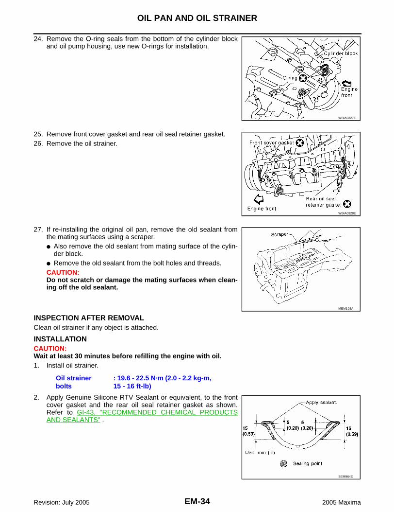
24. Remove the O-ring seals from the bottom of the cylinder blockand oil pump housing, use new O-rings for installation.
25. Remove front cover gasket and rear oil seal retainer gasket.26. Remove the oil strainer.
27. If re-installing the original oil pan, remove the old sealant fromthe mating surfaces using a scraper.● Also remove the old sealant from mating surface of the cylin-
der block.● Remove the old sealant from the bolt holes and threads.CAUTION:Do not scratch or damage the mating surfaces when clean-ing off the old sealant.
INSPECTION AFTER REMOVALClean oil strainer if any object is attached.
INSTALLATIONCAUTION:Wait at least 30 minutes before refilling the engine with oil.1. Install oil strainer.
2. Apply Genuine Silicone RTV Sealant or equivalent, to the frontcover gasket and the rear oil seal retainer gasket as shown.Refer to GI-43, "RECOMMENDED CHEMICAL PRODUCTSAND SEALANTS" .
WBIA0327E
WBIA0328E
MEM108A
Oil strainer bolts
: 19.6 - 22.5 N·m (2.0 - 2.2 kg-m, 15 - 16 ft-lb)
SEM964E

OIL PAN AND OIL STRAINER
EM-35
C
D
E
F
G
H
I
J
K
L
M
A
EM
Revision: July 2005 2005 Maxima
3. Install the front cover gasket and rear oil seal retainer gasket asshown.
4. Apply a bead of sealant to the cylinder block mating surface ofthe upper oil pan to a limited portion as shown.● Use Genuine Silicone RTV Sealant, or equivalent. Refer to
GI-43, "RECOMMENDED CHEMICAL PRODUCTS ANDSEALANTS" .
● Be sure the sealant is applied to a limited portion as shown,and the sealant is 4.0 - 5.0 mm (0.157 - 0.197 in) or 4.5 - 5.5mm (0.177 - 0.217 in) wide.
● Attaching should be done within 5 minutes after coating.
5. Install new O-rings on the cylinder block and oil pump body.
6. Install the upper oil pan.● Tighten upper oil pan bolts in the order shown refer to EM-31,
"Removal and Installation" .● Wait at least 30 minutes before refilling the engine with oil.
WBIA0328E
SEM185FA
SEM159F
WBIA0327E
LBIA0359E

EM-36Revision: July 2005
OIL PAN AND OIL STRAINER
2005 Maxima
7. Install the four upper oil pan to transaxle bolts. Refer to EM-120,"INSTALLATION" .
8. Apply a continuous bead of sealant to the lower oil pan.● Use Genuine Silicone RTV Sealant, or equivalent. Refer to
GI-43, "RECOMMENDED CHEMICAL PRODUCTS ANDSEALANTS" .
● Be sure the sealant is 4.5 - 5.5 mm (0.177 - 0.217 in) wide.● Installation must be done within 5 minutes after applying seal-
ant.
9. Install the lower oil pan. Tighten the lower oil pan bolts in ordershown.
● Wait at least 30 minutes before refilling the engine with oil.
10. Install rear plate cover.
11. Installation of the remaining components is in the reverse orderof removal.
INSPECTION AFTER INSTALLATION● Start the engine and check for leaks. Refer to MA-16, "Changing Engine Oil" .● Inspect the engine oil level. Refer to MA-16, "Changing Engine Oil" .
SEM469G
SEM159F
Lower oil pan bolts : 9.22 - 10.6 N·m (0.94 - 1.00 kg-m, 82 - 93 in-lb)
WBIA0261E
Rear plate cover bolt
: 6.37 - 7.45 N·m (0.65 - 0.75 kg-m, 57 - 65 in-lb)
SEM717G

IGNITION COIL
EM-37
C
D
E
F
G
H
I
J
K
L
M
A
EM
Revision: July 2005 2005 Maxima
IGNITION COIL PFP:22448
Removal and Installation EBS00JAS
REMOVAL1. Remove the engine cover using power tool.2. Drain engine coolant. Refer to MA-14, "DRAINING ENGINE COOLANT" .3. Disconnect the mass air flow sensor electrical connector and remove the air cleaner assembly and air
intake tubes. Refer to EM-16, "Removal and Installation" .4. Remove the intake manifold collector, gasket, and electric throttle control actuator. Refer to EM-18,
"Removal and Installation" .5. Remove the six ignition coils.
CAUTION:Do not shock it.
INSTALLATIONInstallation is in the reverse order of removal.
WBIA0264E
1. Ignition coil 2. Spark plug 3. Rocker cover (right bank)
4. Rocker cover (left bank)

EM-38Revision: July 2005
SPARK PLUG (PLATINUM-TIPPED TYPE)
2005 Maxima
SPARK PLUG (PLATINUM-TIPPED TYPE) PFP:22401
Removal and Installation EBS00JAT
REMOVAL1. Remove the engine cover, using power tool.2. Drain engine coolant. Refer to MA-14, "DRAINING ENGINE COOLANT" .3. Disconnect the mass air flow sensor electrical connector and remove the air cleaner assembly and air
intake tubes. Refer to EM-16, "Removal and Installation" .4. Remove the intake manifold collector, gasket, and electric throttle control actuator. Refer to EM-18,
"Removal and Installation" .5. Remove the six ignition coils.
CAUTION:Do not shock it.
6. Remove the six spark plugs using a suitable tool.● If replacing the spark plugs use the correct spark plug for
maximum performance. Refer to MA-18, "Changing SparkPlugs (Platinum - Tipped Type)" .
WBIA0264E
1. Ignition coil 2. Spark plug 3. Rocker cover (right bank)
4. Rocker cover (left bank)
SEM294A

SPARK PLUG (PLATINUM-TIPPED TYPE)
EM-39
C
D
E
F
G
H
I
J
K
L
M
A
EM
Revision: July 2005 2005 Maxima
INSPECTION AFTER REMOVALDo not use a wire brush for cleaning.
If plug tip is covered with carbon, a spark plug cleaner may be used.
Checking and adjusting plug gap is not required between change intervals.
INSTALLATIONInstallation is in the reverse order of removal.Use standard type spark plug for normal driving conditions. Refer to EM-151, "SPARK PLUG" .The hot type spark plug is suitable when fouling occurs with the standard type spark plug under conditionssuch as:● Frequent engine starts● Low ambient temperaturesThe cold type spark plug is suitable when engine spark knock occurs with the standard type spark plug underconditions such as:● Extended highway driving● Frequent high engine revolution
SMA773C
Cleaner air pressure : less than 588 kPa (6 kg/cm2 , 85 psi)Cleaning time : less than 20 seconds
Gap (nominal) : 1.1 mm (0.043 in)
SMA806CA

EM-40Revision: July 2005
FUEL INJECTOR AND FUEL TUBE
2005 Maxima
FUEL INJECTOR AND FUEL TUBE PFP:16600
Removal and Installation EBS00JAU
CAUTION:● Apply new engine oil when installing the parts as specified to do so.● Do not remove or disassemble parts unless instructed as shown.
REMOVAL1. Remove the intake manifold collector. Refer to EM-18, "Removal and Installation" .2. To remove the quick connector cap, hold the sides of the connector, push in the tabs and pull out the tube.
NOTE:If the connector and the tube are stuck together, push and pull several times until they start to move. Thendisconnect them by pulling.CAUTION:● The tube can be removed when the tabs are completely depressed. Do not twist it more than
necessary.● Do not use any tools to remove the quick connector.● Keep the resin tube away from heat. Be especially careful when welding near the tube.● Prevent acid liquids such as battery electrolyte, etc. from getting on the resin tube.● Do not bend or twist the tube during removal or installation.● Do not remove the remaining retainer on the tube.
WBIA0263E
1. Insulator 2. Fuel tube assembly 3. Connector cap
4. Clip 5. Fuel hose 6. Connector cap
7. O-ring 8. Fuel injector 9. Clip
10. Fuel damper 11. Fuel damper retainer 12. O-ring

FUEL INJECTOR AND FUEL TUBE
EM-41
C
D
E
F
G
H
I
J
K
L
M
A
EM
Revision: July 2005 2005 Maxima
● When the tube is replaced, also replace the retainer with a new one.● To keep the connecting portion clean and to avoid dam-
age and foreign materials entering, cover the ends of thefuel tubes with plastic bags or something similar.
3. Remove the fuel rail with the fuel injectors attached, from theintake manifold. Remove the fuel injector O-rings and use newO-rings for installation.
4. If necessary, remove fuel damper bolts and the fuel dampers.Remove fuel damper O-rings and use new O-rings for installa-tion.
INSTALLATION1. If necessary, Install fuel damper bolts. Use new O-rings for installation.
2. Install the fuel rails with fuel injectors attached.NOTE:● Carefully install new O-rings.● Lubricate O-rings by lightly coating with new engine oil.● Be careful not to damage the O-rings and surfaces for O-ring
sealing surfaces. Do not expand or twist O-rings.● Discard old clips; replace with new ones.● Make sure that protrusions of fuel injectors are aligned with
cutouts of clips after installation.● Position clips in grooves on the fuel injectors.● Align the protrusions of the fuel tube assembly with those of
the fuel injectors.● After properly inserting the fuel injectors onto the fuel tube
assembly, check that the fuel tube protrusions are engaged with those of fuel injectors, and the flangesof the fuel tube assembly are fully engaged with the clips.
3. Tighten fuel tube assembly bolts in the order shown, in twosteps:
CAUTION:● After properly connecting fuel tube assembly to injector
and fuel hose, check connection for fuel leakage.4. Install the quick connector as follows:a. Make sure no foreign substances are deposited in and around the fuel tube and quick connector and that
there is no damage. b. Align the center to insert the quick connector straight onto the fuel tube.c. Insert the fuel tube until a click is heard.5. Installation of the remaining components is in the reverse of removal.
INSPECTION AFTER INSTALLATIONMake sure there is no fuel leakage at connections as follows:1. Apply fuel pressure to fuel lines by turning ignition switch ON (with engine stopped). Then check for fuel
leaks at connections. 2. Start the engine and rev it up and check for fuel leaks at connections.
PBIC0163E
Fuel damper bolts : 7.2 - 10.8 (0.8 - 1.1 kg-m, 64 - 95 in-lb)
Fuel tube assembly boltsStep 1 : 9.3 - 10.8 N·m (0.95 - 1.1 kg-m,
6.2 - 7.9 ft-lb)Step 2 : 20.6 - 26.5 N·m (2.1 - 2.7 kg-m,
16 - 19 ft-lb)
WBIA0287E
WBIA0255E

EM-42Revision: July 2005
FUEL INJECTOR AND FUEL TUBE
2005 Maxima
NOTE:Use mirrors for checking on connections out of the direct line of sight.CAUTION:Do not touch engine immediately after stopping as engine is extremely hot.

ROCKER COVER
EM-43
C
D
E
F
G
H
I
J
K
L
M
A
EM
Revision: July 2005 2005 Maxima
ROCKER COVER PFP:13264
Removal and Installation EBS00JAV
REMOVAL1. Remove the engine cover using power tool. Remove side engine covers.2. If removing RH rocker cover, disconnect the mass air flow sensor electrical connector and remove the air
cleaner to electric throttle control actuator tube and air cleaner lid. Refer to EM-16, "Removal and Installa-tion" .
3. If removing RH rocker cover, remove the front cowl panel. Refer to EI-19, "Removal and Installation" .4. If removing RH rocker cover, remove the windshield wiper arms and motor assembly. Refer to WW-23,
"Removal and Installation of Wiper Motor and Linkage" .5. If removing RH rocker cover, remove the intake manifold collector. Refer to EM-18, "Removal and Instal-
lation" .6. If removing LH rocker cover, disconnect the air fuel (A/F) ratio sensor.7. Remove the ignition coils. Refer to EM-37, "Removal and Installation" .8. Position engine harness aside.9. Disconnect PCV hose.10. Remove dipstick.
WBIA0286E
1. PCV hose 2. Oil filler cap 3. Rocker cover (RH)
4. PCV valve 5. O-ring 6. Rocker cover gasket
7. Rocker cover (LH)

EM-44Revision: July 2005
ROCKER COVER
2005 Maxima
11. Remove rocker covers bolts in the order shown.
INSTALLATIONInstallation is in the reverse order of removal.● Apply sealant to the areas on the front corners. Refer to EM-117,
"Removal and Installation" .● Use Genuine Silicone RTV Sealant or equivalent. Refer to GI-
43, "RECOMMENDED CHEMICAL PRODUCTS AND SEAL-ANTS" .
● Tighten the rocker cover bolts in two steps in the order shown.
LBIA0078E
Rocker cover boltsStep 1 : 0.96 - 2.96 N·m (0.10 - 0.30 kg-m, 9 - 26 in-lb)Step 2 : 7.33 - 9.33 N·m (0.75 - 0.95 kg-m, 65 - 82 in-lb)
WBIA0039E

ROCKER COVER
EM-45
C
D
E
F
G
H
I
J
K
L
M
A
EM
Revision: July 2005 2005 Maxima
● Install engine cover.
WBIA0326E
EM-46Revision: July 2005
FRONT TIMING CHAIN CASE
2005 Maxima
FRONT TIMING CHAIN CASE PFP:13599
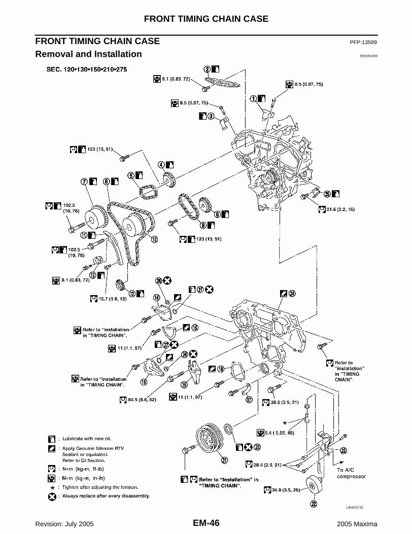
Removal and Installation EBS00JAW
LBIA0371E

FRONT TIMING CHAIN CASE
EM-47
C
D
E
F
G
H
I
J
K
L
M
A
EM
Revision: July 2005 2005 Maxima
NOTE:● This section describes procedures for removal/installation procedure of the front timing chain case and
timing chain related parts without removing the oil pan (upper) from the vehicle.● When oil pan (upper) needs to be removed or installed, or when rear timing chain case is removed or
installed, remove oil pans (upper and lower) first. Then remove front timing chain case, timing chainrelated parts, and rear timing chain case in this order, and install in reverse order of removal. Refer to EM-58, "TIMING CHAIN" .
● Refer to EM-58, "TIMING CHAIN" for component parts location.
REMOVAL1. Release the fuel pressure. Refer to EC-93, "FUEL PRESSURE RELEASE" .2. Disconnect the battery negative terminal.3. Drain the engine cooling system. Refer to MA-14, "DRAINING ENGINE COOLANT" .4. Drain engine oil. Refer to MA-16, "Changing Engine Oil" .5. Remove engine cover using power tool. Remove side engine
covers.6. Remove the intake air duct with the air cleaner case lid and
mass air flow sensor. Refer to EM-16, "REMOVAL" .7. Remove the engine coolant reservoir. Refer to CO-12, "RADIA-
TOR" .
1. Timing chain tensioner (secondary) 2. Internal chain guide 3. Timing chain tensioner (secondary)
4. Camshaft sprocket (EXH) 5. Timing chain (secondary) 6. Timing chain (primary)
7. Camshaft sprocket (INT) 8. Camshaft sprocket (EXH) 9. Timing chain (secondary)
10. Camshaft sprocket (INT) 11. Slack guide 12. Crankshaft sprocket
13. Timing chain tensioner (primary) 14. IVT control valve cover - right 15. Chain tensioner cover
16. RH engine mounting bracket 17. Water hose clamp 18. Water pump cover
19. IVT control valve cover - left 20. Front oil seal 21. Crankshaft pulley
22. Idler pulley 23. Idler pulley bracket 24. Front timing chain case
25. Timing tension guide 26. Collared O-ring 27. Seal ring
WBIA0339E

EM-48Revision: July 2005
FRONT TIMING CHAIN CASE
2005 Maxima
8. Disconnect the fuel rail quick connector at the vehicle pipingside. Refer to EM-40, "REMOVAL" .
9. Remove the cowl top. Refer to EI-19, "Removal and Installation".
10. Remove the windshield wiper assembly. Refer to WW-23,"REMOVAL" .
11. Remove the IPDM E/R and position aside. Remove the bracket.12. Remove the front RH wheel and tire using power tool. Refer to
WT-4, "WHEEL AND TIRE ASSEMBLY" .13. Remove the engine undercover.14. Remove the RH inner fender splash shield.15. Remove the drive belts and idler pulley. Refer to EM-15, "REMOVAL" .16. Recover the A/C system R134a and remove the A/C compressor. Refer to ATC-119, "Evacuating System
and Charging Refrigerant" .17. Remove engine oil cooler pipe bolts.18. Remove the power steering oil pump and reservoir tank with lines attached and position them aside.19. Remove the lower oil pans. Refer to EM-31, "REMOVAL" . 20. Remove the generator. Refer to SC-31, "REMOVAL" .21. Disconnect the engine harness and position aside.22. Remove A/C low pressure line. Refer to ATC-125, "Removal and Installation for Low-pressure Flexible
Hose"23. Support the engine and remove the RH engine mounting insulator, mount and bracket. Refer to EM-117,
"Removal and Installation" .24. Remove the water pump cover and chain tensioner cover from the front timing chain case using Tool.
● Be careful not to damage the mating surface.● Do not insert a screwdriver, this will damage the mating surfaces.
25. Remove the IVT control covers, right and left. Loosen the IVTcontrol cover bolts in the order shown.NOTE:The shaft in the cover is inserted into the center hole of theintake camshaft sprocket. Remove the cover by pulling straightout until the cover disengages from the camshaft sprocket.
26. On A/T vehicles, remove the starter motor. Refer to SC-18, "5-Speed A/T Models" .
27. Remove the intake manifold collector. Refer to EM-19,"REMOVAL" .
Tool number : KV10111100 (J37228)
LBIA0370E
WBIA0260E

FRONT TIMING CHAIN CASE
EM-49
C
D
E
F
G
H
I
J
K
L
M
A
EM
Revision: July 2005 2005 Maxima
28. Remove the six ignition coils.NOTE:Note locations for installation.
29. Remove the six spark plugs.30. Remove the engine oil dipstick.
31. If necessary, remove the rocker covers. Loosen the rocker cov-ers bolts in the order shown. NOTE:Necessary only when removing secondary timing chains.
32. Remove the IVT control solenoid valves.● Discard the gaskets and use new gaskets for installation.
WBIA0048E
LBIA0078E
WBIA0169E

EM-50Revision: July 2005
FRONT TIMING CHAIN CASE
2005 Maxima
33. Obtain compression TDC of No. 1 cylinder as follows:a. Rotate crankshaft pulley clockwise to align timing mark (grooved
line without color) with timing indicator.
b. Check that intake and exhaust camshaft lobes on No. 1 cylinder (right bank of engine) are located as shown.● If not, turn the crankshaft one revolution (360°) and align as
shown.
34. Install Tool as shown.
CAUTION:Do not damage the ring gear teeth, or the signal plate teethbehind the ring gear, when setting the stopper.
35. Remove the crankshaft pulley as follows: a. Loosen crankshaft pulley mounting bolt using pulley holder and
locate bolt seating surface at 10 mm (0.39 in) from its originalposition.
SEM918G
SEM418G
Tool number : KV10117700 (J-44716)
WBIA0270E
WBIA0271E
PBIC0885E

FRONT TIMING CHAIN CASE
EM-51
C
D
E
F
G
H
I
J
K
L
M
A
EM
Revision: July 2005 2005 Maxima
b. Position a pulley puller at recess hole of crankshaft pulley toremove crankshaft pulley.CAUTION:Do not use a puller claw on crankshaft pulley periphery.
36. Loosen the lower oil pan bolts using power tool in order shown.
37. Remove the lower oil pan.a. Insert Tool between the lower oil pan and the upper oil pan.
● Be careful not to damage the mating surface.● Do not insert a screwdriver, this will damage the mating sur-
faces.b. Slide the Tool by tapping its side with a hammer to remove the
lower oil pan from the upper oil pan.
38. Loosen upper oil pan front bolts in the order shown.
EMQ0477D
WBIA0258E
SEM365E
WBIA0259E

EM-52Revision: July 2005
FRONT TIMING CHAIN CASE
2005 Maxima
39. Loosen the bolts in the order shown, using power tool.
a. Insert an appropriate size tool into the notch (1) of the upper oilpan as shown.
b. Pry off the upper oil pan by moving the tool up and down (2) asshown.
40. Temporarily install lower oil pan.41. Support front of engine under oil pan using a jack.42. Remove the front timing chain case.a. Loosen the front timing chain case bolts in the order shown.
b. Insert the appropriate size tool into the notch (1) at the top of thefront timing chain case as shown.
c. Pry off the case by moving the suitable tool (2) as shown.● Cut liquid gasket for removal using Tool.
CAUTION:● Do not use a screwdriver or similar tool.● After removal, handle carefully so it does not bend, or
warp under a load.
LBIA0358E
SEM155F
WBIA0290E
Tool number : KV10111100 (J37228)
SEM156F

FRONT TIMING CHAIN CASE
EM-53
C
D
E
F
G
H
I
J
K
L
M
A
EM
Revision: July 2005 2005 Maxima
43. Remove the front oil seal from the front timing chain case usinga suitable tool.CAUTION:Do not damage the front cover.
44. Use a scraper to remove all of the old Silicone RTV Sealant fromthe front timing chain case and opposite mating surfaces.CAUTION:Do not damage the mating surfaces.
INSTALLATION1. Install timing chain and related parts. Refer to EM-70, "INSTALLATION" .2. Install dowel pins (right and left) into front timing chain case up
to a point close to taper in order to shorten protrusion length.
3. Install the front oil seal on the front timing chain case. Apply new engine oil to the oil seal edges.● Install it so that each seal lip is oriented as shown.
SEM829E
SEM428G
PBIC1101E
SEM715A

EM-54Revision: July 2005
FRONT TIMING CHAIN CASE
2005 Maxima
● Make sure the garter spring is in position and seal lip is notinverted.
4. Apply Silicone RTV Sealant to front timing chain case as shown.● Use Genuine Silicone RTV Sealant, or equivalent. Refer to
MA-9, "RECOMMENDED FLUIDS AND LUBRICANTS" .● Before installation, wipe off the protruding sealant.● Install dowel pin on the rear timing chain case into dowel pin
hole in front timing chain case.
5. Apply Silicone RTV Sealant to top surface of oil pan (upper) asshown.● Use Genuine Silicone RTV Sealant, or equivalent. Refer to
MA-9, "RECOMMENDED FLUIDS AND LUBRICANTS" .
6. Install front timing chain case.a. Install lower end of front timing chain case tightly onto top sur-
face of oil pan (upper).CAUTION:Be careful that oil pan gasket is in place.
PBIC0790E
PBIC1133E
PBIC1099E
PBIC1100E
FRONT TIMING CHAIN CASE
EM-55
C
D
E
F
G
H
I
J
K
L
M
A
EM
Revision: July 2005 2005 Maxima
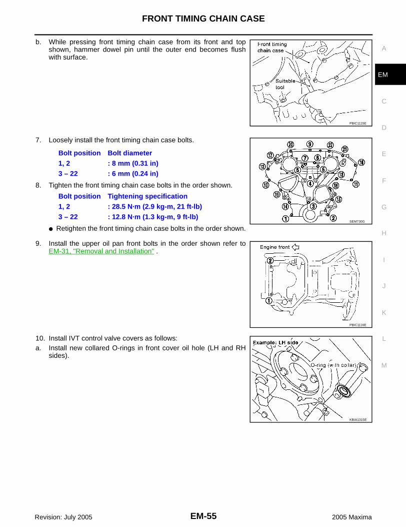
b. While pressing front timing chain case from its front and topshown, hammer dowel pin until the outer end becomes flushwith surface.
7. Loosely install the front timing chain case bolts.
8. Tighten the front timing chain case bolts in the order shown.
● Retighten the front timing chain case bolts in the order shown.
9. Install the upper oil pan front bolts in the order shown refer toEM-31, "Removal and Installation" .
10. Install IVT control valve covers as follows:a. Install new collared O-rings in front cover oil hole (LH and RH
sides).
PBIC1115E
Bolt position Bolt diameter1, 2 : 8 mm (0.31 in)3 – 22 : 6 mm (0.24 in)
Bolt position Tightening specification1, 2 : 28.5 N·m (2.9 kg-m, 21 ft-lb)3 – 22 : 12.8 N·m (1.3 kg-m, 9 ft-lb)
SEM730G
PBIC1116E
KBIA1315E

EM-56Revision: July 2005
FRONT TIMING CHAIN CASE
2005 Maxima
b. Install new seal rings on the IVT control covers.c. Apply Silicone RTV Sealant to the IVT control covers.
● Use Genuine Silicone RTV Sealant, or equivalent. Refer toGI-43, "RECOMMENDED CHEMICAL PRODUCTS ANDSEALANTS" .
● Being careful not to move the seal ring from the installationgroove, align the dowel pins on the chain case with the holesto install the IVT control covers.
● Tighten the intake valve timing control cover bolts in the ordershown refer to EM-46, "Removal and Installation" .
11. Apply liquid gasket and install the water pump cover and thechain tensioner cover refer to EM-46, "Removal and Installation". ● Use Genuine Silicone RTV Sealant or equivalent. Refer to GI-
43, "RECOMMENDED CHEMICAL PRODUCTS AND SEAL-ANTS" .
12. Install crankshaft pulley and tighten the bolt in two steps.● Lubricate thread and seat surface of the bolt with new engine
oil.● For the second step of angle tightening use Tool.
13. Remove Tool.
SEM437G
SEM728G
SEM744GA
Step 1 : 39 - 49 N·m (4.0 - 5.0 kg-m, 29 - 36 ft-lb)Step 2 : 84° - 90° degrees clockwise
Tool number : KV10112100 (BT-8653-A)
SEM531G
Tool number : KV10117700 (J-44716)
WBIA0270E

FRONT TIMING CHAIN CASE
EM-57
C
D
E
F
G
H
I
J
K
L
M
A
EM
Revision: July 2005 2005 Maxima
14. Rotate crankshaft pulley in normal direction (clockwise when viewed from front) to confirm it turnssmoothly.
15. Installation of the remaining components is in the reverse order of removal.NOTE:If hydraulic pressure inside chain tensioner drops after removal/installation, slack in the guide may gener-ate a pounding noise during and just after engine start. This is normal. Noise will stop after hydraulic pres-sure rises.
WBIA0271E

EM-58Revision: July 2005
TIMING CHAIN
2005 Maxima
TIMING CHAIN PFP:13028
Removal and Installation EBS00JAX
WBIA0373E

TIMING CHAIN
EM-59
C
D
E
F
G
H
I
J
K
L
M
A
EM
Revision: July 2005 2005 Maxima
CAUTION:● After removing timing chain, do not turn the crankshaft and camshaft separately, or the valves will
strike the pistons.● When installing camshafts, chain tensioners, oil seals, or other sliding parts, lubricate contacting
surfaces with new engine oil.● Apply new engine oil to bolt threads and seat surfaces when installing camshaft sprockets, cam-
shaft brackets, and crankshaft pulley.● Before disconnecting fuel hose, release fuel pressure. Refer to EC-93, "FUEL PRESSURE
RELEASE" .● Before removing the upper oil pan, remove the crankshaft position sensor (POS).● Be careful not to damage sensor edges.● Do not spill engine oil or coolant on drive belts.NOTE:● This section describes procedures for removal/installation procedure of the front timing chain case and
timing chain related parts, and rear timing chain case, when oil pan (upper) needs to be removed/installedfor engine overhaul, etc.
● To remove/install front timing chain case, timing chain, and its related parts without removing oil pan(upper), refer to EM-46, "Removal and Installation" .
REMOVAL1. Release the fuel pressure. Refer to EC-93, "FUEL PRESSURE RELEASE" .2. Disconnect the battery negative terminal.3. Drain the engine cooling system. Refer to MA-14, "DRAINING ENGINE COOLANT" .4. Drain engine oil. Refer to MA-16, "Changing Engine Oil" .5. Remove engine cover using power tool. 6. Remove side engine covers.7. Remove the intake air duct with the air cleaner case lid and mass air flow sensor. Refer to EM-16,
"Removal and Installation" .8. Remove the engine coolant reservoir. 9. Disconnect the fuel rail quick connector at the vehicle piping
side. 10. Remove the cowl top. Refer to EI-19, "Removal and Installation"
.11. Remove the windshield wiper assembly. Refer to WW-23,
"Removal and Installation of Wiper Motor and Linkage" .12. Remove the IPDM E/R and position aside. Remove the bracket.13. Remove the front RH wheel and tire using power tool. 14. Remove the engine undercover.15. Remove the RH inner fender splash shield.16. Remove the drive belts and idler pulley. Refer to EM-15,
"Removal and Installation" .17. Recover the A/C system R134a and remove the A/C compressor. Refer to ATC-119, "Evacuating System
and Charging Refrigerant" .
1. Timing chain tensioner 2. Internal chain guide 3. Timing chain tensioner
4. Camshaft sprocket (EXH) 5. Timing chain (secondary) 6. Timing chain (primary)
7. Camshaft sprocket (INT) 8. Camshaft sprocket (EXH) 9. Timing chain (secondary)
10. Camshaft sprocket (INT) 11. Slack guide 12. Crankshaft sprocket
13. Timing chain tensioner 14. IVT control valve cover - right 15. Chain tensioner cover
16. RH engine mounting bracket 17. Water hose clamp 18. Water pump cover
19. IVT control valve cover - left 20. Front oil seal 21. Crankshaft pulley
22. Idler pulley 23. Idler pulley bracket 24. Front timing chain case
25. Rear timing chain case 26. Timing tension guide 27. O-ring
28. Collared O-ring 29. Seal ring
LBIA0370E

EM-60Revision: July 2005
TIMING CHAIN
2005 Maxima
18. Remove engine oil cooler pipe bolts.19. Remove the power steering oil pump and reservoir tank with lines attached and position them aside.20. Remove the upper and lower oil pans. Refer to EM-31, "Removal and Installation" . 21. Remove the generator. Refer to SC-31, "Removal and Installation" .22. Disconnect the engine harness and position aside.23. Remove the A/C low pressure line. Refer to ATC-125, "Removal and Installation for Low-pressure Flexible
Hose" .24. Support the engine and remove the RH engine mounting insulator, mount and bracket. Refer to EM-117,
"Removal and Installation" .25. Remove the chain tensioner cover and water pump cover.26. Remove the IVT control covers, right and left. Loosen the IVT
control cover bolts in the order shown.NOTE:The shaft in the cover is inserted into the center hole of theintake camshaft sprocket. Remove the cover by pulling straightout until the cover disengages from the camshaft sprocket.
27. On A/T vehicles, remove the starter motor. Refer to SC-18, "5-Speed A/T Models" .
28. Remove the intake manifold collector. Refer to EM-19,"REMOVAL" .
29. Remove the six ignition coils.NOTE:Note locations for installation.
30. Remove the six spark plugs.31. Remove the engine oil dipstick.
WBIA0260E
WBIA0048E

TIMING CHAIN
EM-61
C
D
E
F
G
H
I
J
K
L
M
A
EM
Revision: July 2005 2005 Maxima
32. Remove the rocker covers. Loosen the rocker covers bolts in theorder shown.
33. Remove the IVT control solenoid valves.● Discard the gaskets and use new gaskets for installation.
34. Obtain compression TDC of No. 1 cylinder as follows:a. Rotate crankshaft pulley clockwise to align timing mark (grooved
line without color) with timing indicator.
b. Check that intake and exhaust camshaft lobes on No. 1 cylinder (right bank of engine) are located as shown.● If not, turn the crankshaft one revolution (360°) and align as
shown.
LBIA0078E
WBIA0169E
SEM918G
SEM418G

EM-62Revision: July 2005
TIMING CHAIN
2005 Maxima
35. Install Tool as shown.
CAUTION:Do not damage the ring gear teeth, or the signal plate teethbehind the ring gear, when setting the stopper.
36. Remove the crankshaft pulley as follows: a. Loosen crankshaft pulley mounting bolt using pulley holder and
locate bolt seating surface at 10 mm (0.39 in) from its originalposition.
b. Position a pulley puller at recess hole of crankshaft pulley toremove crankshaft pulley.CAUTION:Do not use a puller claw on crankshaft pulley periphery.
37. Loosen the lower oil pan bolts using power tool in order shown.
Tool number : KV10117700 (J-44716)
WBIA0270E
WBIA0271E
PBIC0885E
EMQ0477D
WBIA0258E

TIMING CHAIN
EM-63
C
D
E
F
G
H
I
J
K
L
M
A
EM
Revision: July 2005 2005 Maxima
38. Remove the lower oil pan.a. Insert Tool between the lower oil pan and the upper oil pan.
● Be careful not to damage the mating surface.● Do not insert a screwdriver, this will damage the mating sur-
faces.b. Slide the Tool by tapping its side with a hammer to remove the
lower oil pan from the upper oil pan.
39. Loosen upper oil pan front bolts in the order shown.
40. Loosen the bolts in the order shown, using power tool.
a. Insert an appropriate size tool into the notch (1) of the upper oilpan as shown.
b. Pry off the upper oil pan by moving the tool up and down (2) asshown.
41. Temporarily install lower oil pan.42. Support front of engine under oil pan using a jack.
SEM365E
WBIA0259E
LBIA0358E
SEM155F

EM-64Revision: July 2005
TIMING CHAIN
2005 Maxima
43. Remove the front timing chain case.a. Loosen the front timing chain case bolts in the order shown.
b. Insert the appropriate size tool into the notch (1) at the top of thefront timing chain case as shown.
c. Pry off the case by moving the suitable tool (2) as shown.● Use seal cutter or an equivalent tool to cut liquid gasket for
removal.CAUTION:● Do not use a screwdriver or similar tool.● After removal, handle carefully so it does not bend, or
warp under a load.
44. Remove the front oil seal from the front timing chain case usinga suitable tool.CAUTION:Do not damage the front cover.
45. Use a scraper to remove all of the old Silicone RTV Sealant fromthe front timing chain case and opposite mating surfaces.CAUTION:Do not damage the mating surfaces.
WBIA0290E
SEM156F
SEM829E
SEM428G

TIMING CHAIN
EM-65
C
D
E
F
G
H
I
J
K
L
M
A
EM
Revision: July 2005 2005 Maxima
46. Remove the internal chain guide.
47. Remove the timing chain tensioner and slack guide.● Place paint marks on the timing chain and sprockets to indicate the correct position of the components
for installation.a. Pull lever down and release plunger stopper tab. Plunger stop-
per tab can be pushed up to release (coaxial structure withlever).
b. Insert stopper pin into tensioner body hole to hold lever, andkeep the tab released. An Allen wrench [2.5 mm (0.098 in)] isused for a stopper pin as an example.
c. Insert plunger into tensioner body by pressing the slack sidechain guide.
d. Keep the slack side chain guide pressed and hold it by pushingthe stopper pin through the lever hole and body hole.
e. Remove the timing chain tensioner installation bolts and removethe timing chain tensioner.
f. Remove slack guide installation bolt and the slack guide.48. Remove primary timing chain and crankshaft sprocket.
CAUTION:After removing timing chain, do not turn the crankshaft andcamshaft separately, or the valves will strike the pistons.
SEM740G
SEM732G
SEM733G

EM-66Revision: July 2005
TIMING CHAIN
2005 Maxima
49. Attach a suitable stopper pin to the right and left camshaft chaintensioners (for secondary timing chains).
50. Remove the intake and exhaust camshaft sprocket bolts.● Apply paint to the timing chain and camshaft sprockets for
alignment during installation.● Secure the hexagonal portion of the camshaft using a wrench
to loosen the bolts as shown.
51. Remove the secondary timing chains with camshaft sprockets.a. Rotate camshaft slightly, and slacken timing chain of timing
chain tensioner side.b. Insert metal or resin plate [0.5 mm (0.020 in)] into guide between
timing chain and chain tensioner plunger. Remove cam sprocketand secondary timing chain with timing chain removed fromguide groove.● Intake camshaft sprocket is two-for-one structure of primary
and secondary sprockets.● Handle the intake sprockets as an assembly.CAUTION:● Chain tensioner plunger can move while stopper pin is inserted in tensioner. Plunger can come
out of tensioner when timing chain is removed. Use caution during removal.● Avoid impact or dropping the intake sprockets.● Do not disassemble the intake sprockets (never loosen
bolts A and B as shown).
52. Remove the timing chain tension guide.
SEM923G
WBIA0172E
SEM922G
SEM734G

TIMING CHAIN
EM-67
C
D
E
F
G
H
I
J
K
L
M
A
EM
Revision: July 2005 2005 Maxima
53. If neccesary remove the water pump.
54. Remove the rear timing chain case.CAUTION:● Do not remove the plate metal cover for the oil passage.● After removing the chain case, do not apply any load to
the case that might bend it.
a. Loosen and remove the rear timing chain case bolts in the ordershown.
b. Cut the sealant using Tool and remove the rear timing chaincase.
55. Disconnect the inlet coolant hose.56. Remove the inlet coolant housing, gasket and thermostat.
LBIA0361E
KBIA1307E
WBIA0078E
Tool number : KV10111100 (J-37228)
SEM279G

EM-68Revision: July 2005
TIMING CHAIN
2005 Maxima
57. Remove O-rings on the cylinder head and cylinder block.
58. Loosen the No. 1 camshaft bracket bolts in several steps in theorder shown and remove No. 1 camshaft brackets.
59. Remove the camshaft chain tensioners (for secondary timingchains).
60. Use a scraper to remove all of the old Silicone RTV Sealant fromthe front and rear timing chain case and opposite mating sur-faces.CAUTION:Do not damage the mating surfaces.
SEM447G
PBIC0788E
LBIA0343E
SEM428G

TIMING CHAIN
EM-69
C
D
E
F
G
H
I
J
K
L
M
A
EM
Revision: July 2005 2005 Maxima
61. Remove all old Silicone RTV Sealant from all the bolt holes andbolts. CAUTION:Do not damage the threads or mating surfaces.
62. Use a scraper to remove all the old Silicone RTV Sealant fromthe water pump cover, chain tensioner cover and IVT controlcovers.CAUTION:Do not damage the mating surfaces.
63. Remove the old Silicone RTV Sealant from the camshaft No. 1bracket mating surface using a scraper.● Do not scratch or damage the mating surface.
64. Remove the front oil seal from the front timing chain case usinga suitable tool.CAUTION:Do not damage the front cover.
SEM161F
WBIA0173E
SEM892E
SEM829E

EM-70Revision: July 2005
TIMING CHAIN
2005 Maxima
INSPECTION AFTER REMOVALCheck for cracks and any excessive wear at the roller links of thetiming chain. Replace the timing chain as necessary.
INSTALLATIONNOTE:The figure shows the relationship between the mating mark on each timing chain and that on the correspond-ing sprocket, with the components installed.
SEM928E
1. Internal chain guide 2. Camshaft sprocket (INT) 3. Mating mark (copper link)
4. Mating mark (punched) 5. Timing chain tensioner (secondary) 6. Mating mark (yellow link)
7. Timing chain (secondary) 8. Camshaft sprocket (EXH) 9. Tensioner guide
10. Water pump 11. Crankshaft sprocket 12. Mating mark (notched)
13. Timing chain (primary) 14. Slack guide 15. Timing chain tensioner (primary)
16. Mating mark (back side) 17. Crankshaft key
WBIA0280E

TIMING CHAIN
EM-71
C
D
E
F
G
H
I
J
K
L
M
A
EM
Revision: July 2005 2005 Maxima
1. Install the camshaft chain tensioners (for secondary timingchains).
2. Before installing No. 1 camshaft bracket, apply sealant to matingsurface.● Use Genuine Silicone RTV Sealant, or equivalent. Refer to
GI-43, "RECOMMENDED CHEMICAL PRODUCTS ANDSEALANTS" .
● Before installation, wipe off any protruding sealant.● Refer to EM-4, "LIQUID GASKET APPLICATION PROCE-
DURE" .
3. Tighten the No. 1 camshaft bracket in three steps, in the ordershown.
4. Install the thermostat, gasket and engine coolant inlet and thermostat assembly.
Camshaft chain ten-sioner bolts
: 8.5 N·m (0.87 kg-m, 75 in-lb)
SEM444G
WBIA0266E
Camshaft bracket boltsStep 1 (bolts 7 - 10) : 1.96 N·m (0.2 kg-m, 17 in-lb)Step 2 (bolts 1 - 6) : 1.96 N·m (0.2 kg-m, 17 in-lb)Step 3 : 5.88 N·m (0.6 kg-m, 52 in-lb)Step 4 (bolts 1 - 6) : 10.4 N·m (1.1 kg-m, 92 in-lb)
LBIA0344E
Coolant inlet housing bolts
: 8.4 - 11.2 N·m (0.86 - 1.14 kg-m, 74.6 - 99.0 in-lb)

EM-72Revision: July 2005
TIMING CHAIN
2005 Maxima
5. Install rear timing chain case as follows:a. Install new O-rings on cylinder block.
b. Install new O-rings on cylinder head.
6. Apply Silicone RTV Sealant to rear timing chain case as shown.
● Use Genuine Silicone RTV Sealant, or equivalent. Refer to GI-43, "RECOMMENDED CHEMICALPRODUCTS AND SEALANTS" .
PBIC0788E
SEM447G
WBIA0336E

TIMING CHAIN
EM-73
C
D
E
F
G
H
I
J
K
L
M
A
EM
Revision: July 2005 2005 Maxima
● Before installation, wipe off the protruding sealant.
7. Align the rear timing chain case with the dowel pins (RH and LH)on the cylinder block and install the case. Make sure the O-ringsstay in place during installation.
a. Loosely install the rear timing chain case in the order shown.There are two bolt lengths used. Follow the chart below forproper bolt length specifications.
b. After all bolts are initially tightened, retighten them in the ordershown.
8. After installing rear timing chain case, check surface height difference between the rear timing chain caseto cylinder block.
● If not within standard, repeat above installation procedure.9. Install the timing chain tension guide.
10. Position the crankshaft so No. 1 piston is set at TDC on thecompression stroke.● Make sure that the dowel pin hole, dowel pin and crankshaft
key are located as shown. Camshaft dowel pin hole (intake side): at cylinder head upperface side in each bank.Camshaft dowel pin (exhaust side): at cylinder head upperface side in each bank.Crankshaft key: at cylinder head side of RH bank.
CAUTION:Hole on small diameter side must be used for intake cam-shaft sprocket dowel pin. Do not misidentify (ignore bigdiameter side).
11. If necessary, install the water pump and water pump bolts.
Bolt position Bolt length 1, 2, 3, 6, 7, 8, 9, 10 20 mm (0.79 in) 4, 5, 11 - 26 16 mm (0.63 in)
Rear timing chain case : 12 - 13 N·m (1.2 - 1.4 kg-m, 9 -10 ft-lb)
SEM735G
Standard : - 0.24 - 0.14 mm (-0.0094 - 0.0055 in)
Timing chain ten-sion guide bolts
: 19.6 - 23.5 N·m (2.0 - 2.3 kg-m, 15 -17 ft-lb)
KBIA1073E
Water pump bolts : 8.5 - 10.7 N·m (0.86 - 1.10 kg-m, 75-95 in-lb)
LBIA0361E

EM-74Revision: July 2005
TIMING CHAIN
2005 Maxima
12. Install the secondary timing chains and camshaft sprockets.CAUTION:Matching marks between the timing chain and sprocketsslip easily. Confirm all matching mark positions repeatedlyduring the installation process.● Push the sleeve of the secondary chain tensioner and keep it
pressed in with a stopper pin.
a. Align the matching marks (4), (5), (7) and (10) on the secondarytiming chain (8) [yellow link (2)] with the ones on the intake andexhaust sprockets (stamped), and install them.● Illustration shows RH (rear view)● Matching marks for the intake sprocket are on the back side
of the secondary sprocket.● There are two types of matching marks, round (7) and (10)
and oval (4) and (5) types. They should be used for the RHand LH banks, respectively.RH bank: use round type (7) and (10).LH (6) bank: use oval type (4) and (5).
b. Align the dowel pin (3) with the pin hole on the camshaftsprocket INT side (1), and the dowel pin groove (11) with thedowel pin on the camshaft EXH side, and install them.● On the intake side, align the pin hole on the small diameter
side of the camshaft front end with the dowel pin (3) on theback side of the camshaft sprocket (1), and install them.
● On the exhaust side, align the dowel pin on the camshaft frontend with the dowel pin groove (11) on the camshaft sprocket(9), and install them.
● Camshaft sprocket bolts must be tightened in the next step.Tightening them by hand is enough to prevent the dislocationof the dowel pin (3) and dowel pin groove (11).
● It may be difficult to visually check the dislocation of matingmarks during and after installation. To make the matchingeasier, make a mating mark on the sprocket teeth in advancewith paint.
SEM430G
WBIA0689E
SEM811G

TIMING CHAIN
EM-75
C
D
E
F
G
H
I
J
K
L
M
A
EM
Revision: July 2005 2005 Maxima
13. After confirming the mating marks are aligned, tighten the cam-shaft sprocket bolts.● Secure the camshaft using a wrench at the hexagonal portion
to tighten the camshaft sprocket bolts.
14. Pull the stopper pins out from the timing chain tensioners (forsecondary timing chains).
15. Install the crankshaft sprocket on the crankshaft.● Make sure the mating marks on the crankshaft sprocket face
the front of the engine.
16. Install the primary timing chain.● Water pump (G).● Install primary timing chain so the mating mark punched (B)
on camshaft sprocket is aligned with the copper link (A) on thetiming chain, while the mating mark notched (E) on the crank-shaft sprocket (D) is aligned with the yellow link (F) on the tim-ing chain, as shown.
● When it is difficult to align mating marks (A) with (B) and (E)with (F) of the primary timing chain with each sprocket, gradu-ally turn the camshaft using a wrench on the hexagonal por-tion to align it with the mating marks.
● During alignment, be careful to prevent dislocation of matingmark alignments of the secondary timing chains.
Camshaft sprocket bolts : 102.5 N·m (10 kg-m, 76 ft-lb)
WBIA0172E
SEM923G
SEM929E
WBIA0721E

EM-76Revision: July 2005
TIMING CHAIN
2005 Maxima
17. Install the internal chain guide.
18. Install the slack guide.● Do not overtighten the slack guide installation bolt. It is normal
for a gap to exist under the bolt seats when the installationbolt is tightened to specification.
19. Install the timing chain tensioner for the slack guide.
● When installing the chain tensioner, push in the sleeve andkeep it pressed in with the stopper pin.
● Remove any dirt and foreign materials completely from theback and the mounting surfaces of the chain tensioner.
● After installation, pull out the stopper pin by pressing the slackguide.
20. Reconfirm that the matching marks on the sprockets and thetiming chain have not slipped out of alignment.
21. Install new O-rings on the rear timing chain case.
Internal chain guide bolts : 8.1 N·m (0.83 kg-m, 72 in-lb)
SEM740G
Slack guide bolt : 15.7 N·m (1.6 kg-m, 12 ft-lb)
SEM741G
Timing chain tensioner bolts
: 8.1 N·m (0.83 kg-m, 72 in-lb)
SEM733G
SEM435G

TIMING CHAIN
EM-77
C
D
E
F
G
H
I
J
K
L
M
A
EM
Revision: July 2005 2005 Maxima
22. Install the front oil seal on the front timing chain case using asuitable tool. Apply clean engine oil to the oil seal edges.● Install it so that each seal lip is oriented as shown.
CAUTION:Press fit straight and avoid causing burrs or tilting the oilseal.
● Using a suitable drift, press-fit oil seal until it becomes flushwith timing chain case end face.
● Make sure the garter spring in the oil seal is in position andseal lip is not inverted.
23. Apply Silicone RTV Sealant to front timing chain case as shown.● Use Genuine Silicone RTV Sealant, or equivalent. Refer to
MA-9, "RECOMMENDED FLUIDS AND LUBRICANTS" .● Before installation, wipe off the protruding sealant.● Install dowel pin on the rear timing chain case into dowel pin
hole in front timing chain case.
24. Apply Silicone RTV Sealant to top surface of oil pan (upper) asshown.● Use Genuine Silicone RTV Sealant, or equivalent. Refer to
MA-9, "RECOMMENDED FLUIDS AND LUBRICANTS" .
Suitable driftOuter diameter : 59 mm (2.32 in)Inner diameter : 49 mm (1.93 in)
SEM715A
PBIC0790E
PBIC1133E
PBIC1099E

EM-78Revision: July 2005
TIMING CHAIN
2005 Maxima
25. Install front timing chain case.a. Install lower end of front timing chain case tightly onto top sur-
face of oil pan (upper).CAUTION:Be careful that oil pan gasket is in place.
b. While pressing front timing chain case from its front and topusing suitable tool, hammer dowel pin until the outer endbecomes flush with surface.
26. Loosely install the front timing chain case bolts.
27. Tighten the front timing chain case bolts in the order shown.● Retighten the front timing chain case bolts in the order shown.
28. After installing the front timing chain case, check the surfaceheight difference between the following parts on the oil panmounting surface.● If not within specification, repeat the installation procedure.
PBIC1100E
PBIC1115E
Bolt position Bolt diameter1, 2 : 8 mm (0.31 in)3 – 22 : 6 mm (0.24 in)
SEM730G
Bolt position Tightening specification1, 2 : 28.5 N·m (2.9 kg-m, 21 ft-lb)3 – 22 : 12.8 N·m (1.3 kg-m, 9 ft-lb)
Front timing chain case to rear timing chain case
: (–0.14) - 0.14 mm [(–0.0055) - 0.0055 in]
Oil pump to cylinder block : (–0.36) - (–0.10) mm [(–0.0142) - (–0.0039) in]
SEM746G

TIMING CHAIN
EM-79
C
D
E
F
G
H
I
J
K
L
M
A
EM
Revision: July 2005 2005 Maxima
29. Install the upper oil pan front bolts in the order shown refer toEM-31, "Removal and Installation" .
30. Install the upper oil pan.● Tighten upper oil pan bolts in the order shown refer to EM-31,
"Removal and Installation" .● Wait at least 30 minutes before refilling the engine with oil.
31. Install the four upper oil pan to transaxle bolts. Refer to EM-120,"INSTALLATION" .
32. Install IVT control valve covers as follows:a. Install new collared O-rings in front cover oil hole (LH and RH
sides).
b. Install new seal rings on the IVT control covers.c. Apply Silicone RTV Sealant to the IVT control covers.
● Use Genuine Silicone RTV Sealant, or equivalent. Refer toMA-9, "RECOMMENDED FLUIDS AND LUBRICANTS" .
PBIC1116E
LBIA0359E
SEM469G
KBIA1315E
SEM437G

EM-80Revision: July 2005
TIMING CHAIN
2005 Maxima
● Being careful not to move the seal ring from the installationgroove, align the dowel pins on the chain case with the holesto install the IVT control covers.
● Tighten the intake valve timing control cover bolts in the ordershown.
33. Apply liquid gasket and install the water pump cover and thechain tensioner cover.
● Use Genuine Silicone RTV Sealant or equivalent. Refer toMA-9, "RECOMMENDED FLUIDS AND LUBRICANTS" .
34. Install the RH engine mounting insulator, mount and bracket. Refer to EM-117, "Removal and Installation".
35. Install the RH and LH rocker covers. Tighten the rocker coverbolts in two steps in the order shown.
Intake valve timing control cover bolts
: 11.3 N·m (1.2 kg-m, 8 ft-lb)
SEM728G
Water pump cover bolts : 11 N·m (1.1 kg-m, 97 in-lb)Chain tensioner cover bolts
: 11 N·m (1.1 kg-m, 97 in-lb)
SEM744GA
Step 1 : 0.96 - 2.96 N·m (0.1 - 0.3 kg-m, 9 - 26 in-lb)Step 2 : 7.33 - 9.33 N·m (0.75 - 0.95 kg-m, 65 - 82 in-lb)
WBIA0039E

TIMING CHAIN
EM-81
C
D
E
F
G
H
I
J
K
L
M
A
EM
Revision: July 2005 2005 Maxima
36. Install the IVT control solenoid valve bank 1 and bank 2.
37. Install the engine oil dipstick.
38. Install the six spark plugs in their original positions.
39. Install the six ignition coils in their original positions.
40. Install the intake manifold collector. Refer to EM-20, "INSTALLA-TION" .
41. Install crankshaft pulley and tighten the bolt in two steps.● Lubricate thread and seat surface of the bolt with new engine
oil.● For the second step of angle tightening use Tool.
42. Remove Tool.
IVT control solenoid valve bolts
: 9.81 - 12.70 N·m (1.0 - 1.2 kg-m, 87 - 112 in-lb)
WBIA0169E
Spark plugs : 20 - 29 N·m (2.0 - 3.0 kg-m, 14 - 22 ft-lb)
Ignition coils : 6.37 - 7.54 N·m (0.65 - 0.76 kg-m, 57 - 66 in-lb)
WBIA0048E
Step 1 : 39 - 49 N·m (4.0 - 5.0 kg-m, 29 - 36 ft-lb)Step 2 : 84° - 90° degrees clockwise
Tool number : KV10112100 (BT-8653-A)
SEM531G
Tool number : KV10117700 (J-44716)
WBIA0270E

EM-82Revision: July 2005
TIMING CHAIN
2005 Maxima
43. Install the starter motor. Refer to SC-17, "Removal and Installation" .44. Install the RH engine mounting insulator, mount and bracket. Refer to EM-117, "Removal and Installation"
.45. Reposition and reconnect the engine harness.46. Install the generator. Refer to SC-31, "INSTALLATION" .47. Install the upper and lower oil pans. Refer to EM-34, "INSTALLATION" .48. Install the power steering pump. Refer to PS-26, "INSTALLATION" .49. Install the A/C compressor and recharge the system. Refer to ATC-122, "Removal and Installation for
Compressor" .50. Install the idler pulley and the drive belts. Refer to EM-15, "Removal and Installation" .51. Install the inner fender splash shield and the engine undercover.52. Connect the inlet coolant hose.53. Install the IPDM E/R and bracket.54. Install the RH wheel and tire. Refer to WT-4, "WHEEL AND TIRE ASSEMBLY" .55. Install the windshield wiper assembly. Refer to WW-23, "INSTALLATION" .56. Install the cowl top grille. Refer to EI-19, "Removal and Installation" .57. Install the fuel hose quick connector to the fuel tube at the vehicle piping side. Refer to EM-41, "INSTAL-
LATION" .58. Install the engine coolant reservoir.59. Install the intake air duct with the air cleaner case lid and mass air flow sensor. Refer to EM-17, "INSTAL-
LATION" .60. Install engine cover.61. Refill the coolant. Refer to MA-14, "REFILLING ENGINE COOL-
ANT" .CAUTION:Wait at least 30 minutes for the Silicone RTV Sealant to setbefore filling the engine with fluids to avoid leaks.
62. Refill the engine oil. Refer to MA-16, "Changing Engine Oil" .CAUTION:Wait at least 30 minutes for the Silicone RTV Sealant to setbefore filling the engine with fluids to avoid leaks.
63. Connect the battery negative terminal.64. Activate the fuel system. Check for any leaks when the system
is repressurized and correct as necessary.65. Start the engine and check all systems for leaks or improper
operation. Correct as necessary.● After starting engine, keep idling for three minutes. Then rev
engine up to 3,000 rpm under no load to purge air from thehigh-pressure oil chamber of the chain tensioners. Theengine may produce a rattling noise. This indicates that airstill remains in the chamber and is not a matter of concern.
WBIA0271E
WBIA0326E

CAMSHAFT
EM-83
C
D
E
F
G
H
I
J
K
L
M
A
EM
Revision: July 2005 2005 Maxima
CAMSHAFT PFP:13001
Removal and Installation EBS00JAY
WBIA0275E
1. Oil filler cap 2. Washer 3. Rocker cover
4. PCV hose 5. IVT control solenoid valve 6. PCV valve
7. Tensioner sleeve 8. Tensioner spring 9. Camshaft chain tensioner
10. Valve 11. Cylinder head 12. Camshaft position sensor (PHASE)
13. Spark plug 14. Valve spring seat 15. Valve spring
16. Valve spring retainer 17. Valve collet 18. Valve lifter
19. Camshaft (EXH) 20. Camshaft (INT) 21. Camshaft bracket
22. Spark plug tube 23. Gasket 24. O-ring
25. Seal washer 26. Dowel pin 27. Valve oil seal

EM-84Revision: July 2005
CAMSHAFT
2005 Maxima
CAUTION:Apply new engine oil to parts marked in illustration before installation.
REMOVAL1. Remove the timing chains. Refer to EM-59, "REMOVAL" .2. If necessary, remove camshaft position sensor (PHASE) (right
and left bank) from cylinder head back side.CAUTION:● Handle carefully to avoid dropping and shocks.● Do not disassemble.● Do not allow any metal particles to adhere to magnetic
part at sensor tip.● Do not place sensors in a location where they are
exposed to magnetism.
3. Remove the IVT control solenoid valves.● Discard the IVT control solenoid valve gaskets and use new
gaskets for installation.
4. Remove the intake and exhaust camshaft brackets and the cam-shafts.● Mark the camshafts, camshaft brackets, and bolts so they are
placed in the same position and direction for installation.● Equally loosen the camshaft bracket bolts in several steps in
the order shown.
5. Remove valve lifters.NOTE:Identify installation positions to ensure proper installation.
KBIA1046E
WBIA0169E
SEM856E
SEM857E

CAMSHAFT
EM-85
C
D
E
F
G
H
I
J
K
L
M
A
EM
Revision: July 2005 2005 Maxima
6. Remove camshaft timing chain tensioner from cylinder headwith the stopper pin inserted.NOTE:Stopper pin was installed when secondary timing chain wasremoved.
SEM444G

EM-86Revision: July 2005
CAMSHAFT
2005 Maxima
INSPECTION AFTER REMOVALCamshaft Visual Check Check camshaft for scratches, seizure and wear. Replace if necessary.
Camshaft Runout1. Put V-block on precise flat bed and support No. 2 and No. 4 jour-
nal of camshaft as shown.2. Set dial gauges vertically to No. 3 journal as shown.3. Turn camshaft in one direction slowly by hand, measure the
camshaft runout on the dial gauges.● Runout is the largest indicator reading after one full revolu-
tion.
4. If actual runout exceeds the limit, replace the camshaft.
Camshaft Cam Lobe Height1. Measure camshaft cam lobe height as shown. Refer to EM-156,
"CAMSHAFT AND CAMSHAFT BEARING" .2. If wear has reduced the lobe height below specifications,
replace the camshaft.
Camshaft Journal ClearanceOuter Diameter of Camshaft Journal● Measure outer diameter of camshaft journal as shown.
Inner Diameter of Camshaft Bracket1. Tighten camshaft bracket bolts to specified torque. Refer to EM-
88, "INSTALLATION" .2. Using inside micrometer, measure inner diameter "A" of cam-
shaft bearing.
Camshaft RunoutStandard : Less than 0.02 mm (0.0008 in)Limit : 0.05 mm (0.0020 in)
PBIC0929E
SEM549A
Standard outer diameter, No.1
: 25.935 - 25.955 mm (1.0211 - 1.0218 in)
Standard outer diameter, No.2, 3, 4
: 23.445 - 23.465 mm (0.9230 - 0.9238 in)
SEM012A
Standard inner diameter No.1
: 26.000 - 26.021 mm (1.0236 - 1.0244 in)
Standard inner diameter No. 2, 3, 4
: 23.500 - 23.521 mm (0.9252 - 0.9260 in)
PBIC1645E

CAMSHAFT
EM-87
C
D
E
F
G
H
I
J
K
L
M
A
EM
Revision: July 2005 2005 Maxima
Calculation of Camshaft Journal Clearance(Journal clearance) = (inner diameter of camshaft bracket) – (outer diameter of camshaft journal)
● When out of the specified range, replace either or both camshaft and cylinder head.NOTICE:Inner diameter of camshaft bracket is manufactured together with cylinder head. Replace the whole cylin-der head assembly.
Camshaft End Play1. Install the camshaft in the cylinder head. Refer to EM-88, "INSTALLATION" .2. Install dial gauge in thrust direction on front end of camshaft.
Measure end play when camshaft is moved forward/backward(in direction to axis) as shown.
● If out of the specified range, replace with new camshaft andmeasure again.
● If out of the specified range again, replace with new cylinderhead.
Camshaft Sprocket Runout1. Put V-block on precise flat bed and support No. 2 and No. 4 jour-
nal of camshaft as shown.2. Install camshaft sprocket on camshaft.3. Measure camshaft sprocket runout.
4. If sprocket runout exceeds the limit, replace camshaft sprocket.
Valve Lifter ● Check if the surface of the valve lifter has any excessive wear or
cracks, replace as necessary.
Standard No.1
: 0.045 - 0.086 mm (0.0018 - 0.0034 in)
Standard No. 2, 3, 4
: 0.035 - 0.076 mm (0.0014 - 0.0030 in)
Limit : 0.15 mm (0.0059 in)
Standard : 0.115 - 0.188 mm (0.0045 - 0.0074 in)Limit : 0.24 mm (0.0094 in)
SEM864E
Limit : 0.15 mm (0.0059 in)
PBIC0930E
KBIA0182E

EM-88Revision: July 2005
CAMSHAFT
2005 Maxima
Valve Lifter ClearanceOuter Diameter of Valve Lifter● Measure the outer diameter of the valve lifter. Refer to EM-153,
"Valve Lifter" .● If out of the specified range, replace the valve lifter.
Valve Lifter Bore Diameter● Using inside micrometer, measure diameter of valve lifter bore
of cylinder head. Refer to EM-153, "Valve Lifter" .● If out of the specified range, replace the cylinder head assembly.
Calculation of Valve Lifter Clearance● (Valve lifter clearance) = (hole diameter for valve lifter) – (outer diameter of valve lifter). Refer to EM-153,
"Valve Lifter" .● If out of specified range, replace either or both valve lifter and cylinder head assembly.
INSTALLATION1. Before installation, remove any old Silicone RTV Sealant from
component mating surfaces using a scraper.● Remove the old Silicone RTV Sealant from the bolt holes and
threads.● Do not scratch or damage the mating surfaces.
2. Before installing the No. 1 camshaft bracket, remove the old Sil-icone RTV Sealant from the mating surface using a scraper.● Do not scratch or damage the mating surface.
JEM798G
SEM867E
SEM161F
SEM892E

CAMSHAFT
EM-89
C
D
E
F
G
H
I
J
K
L
M
A
EM
Revision: July 2005 2005 Maxima
3. Turn the crankshaft until No. 1 piston is set at TDC on the com-pression stroke.● The crankshaft key should line up with the right bank cylinder
center line as shown.
4. Install camshaft chain tensioners on both sides of cylinder head.
5. Install valve lifters.NOTE:Install them in original positions.
6. Install exhaust and intake camshafts and camshaft brackets.● Intake camshaft has a drill mark on camshaft sprocket mount-
ing flange.
● Follow your identification marks made during removal, or fol-low the identification marks that are present on the new cam-shafts components for proper placement and direction of thecomponents.
SEM532G
Camshaft chain tensioner bolts
: 7 - 10 N·m (0.8 - 1.0 kg-m, 62 - 88 in-lb)
SEM444G
SEM652F
Bank INT/EXH ID mark Drill markPaint marks
M1 M2
RHINT RE Yes Yes No
EXH RE No No Yes
LHINT LH Yes Yes No
EXH LH No No YesSEM653F

EM-90Revision: July 2005
CAMSHAFT
2005 Maxima
● Position the camshafts:RH exhaust camshaft dowel pin at about 10 o'clock.LH exhaust camshaft dowel pin at about 2 o'clock.
7. Before installing camshaft brackets, apply sealant to mating sur-face of No. 1 camshaft bracket.● Use Genuine Silicone RTV Sealant, or equivalent. Refer to
GI-43, "RECOMMENDED CHEMICAL PRODUCTS ANDSEALANTS" .
● Before installation, wipe off any protruding sealant.● Refer to EM-4, "LIQUID GASKET APPLICATION PROCE-
DURE" .
● Install camshaft brackets in their original positions and direc-tion. Align the stamp marks as shown.
● If checking and adjusting any part of valve assembly or cam-shaft, check valve clearance according to the reference data.Refer to EM-93, "Valve Clearance" .
KBIA1072E
SEM446G
WBIA0266E
SEM564G

CAMSHAFT
EM-91
C
D
E
F
G
H
I
J
K
L
M
A
EM
Revision: July 2005 2005 Maxima
8. Tighten the camshaft brackets in the four steps, in the ordershown.NOTE:Lubricate the threads and seat surfaces of the camshaft bracketbolts with new engine oil before installation.
9. Measure difference in levels between front end faces of cam-shaft No. 1 bracket and cylinder head.
● If measurement is outside the specified range, re-install cam-shaft and camshaft bracket.
10. Install the IVT control solenoid valves with new gaskets.
11. If necessary, install camshaft position sensor (PHASE) (RH and LH bank.)
12. Install the timing chains. Refer to EM-70, "INSTALLATION" .13. Install the LH and RH rocker cover refer to EM-44, "INSTALLATION" .14. Install the fuel rail and injectors. Refer to EM-40, "Removal and Installation" .15. Installation of the remaining components is in the reverse order of removal.
Camshaft bracket boltsStep 1 (bolts 7 - 10) : 1.96 N·m (0.2 kg-m, 17 in-lb)Step 2 (bolts 1 - 6) : 1.96 N·m (0.2 kg-m, 17 in-lb)Step 3 : 5.88 N·m (0.6 kg-m, 52 in-lb)Step 4 (bolts 1 - 6) : 10.4 N·m (1.1 kg-m, 92 in-lb)
SEM886EA
Standard : – 0.14 (– 0.0055 in)
EMQ0044D
IVT control solenoid valve bolts
: 9.81 - 12.7 N·m (1.0 - 1.2 kg-m, 87 - 112 in-lb)
WBIA0169E
Camshaft position sensor (PHASE) bolt
: 8.4 - 10.8 N·m (0.9 - 1.1 kg-m, 75 - 95 in-lb)

EM-92Revision: July 2005
CAMSHAFT
2005 Maxima
INSPECTION AFTER INSTALLATION EBS00M6V
INSPECTION OF CAMSHAFT SPROCKET (INT) OIL GROOVECAUTION:● Perform this inspection only when DTC P0011 and/or DTC0021 are detected in self-diagnostic
results of CONSULT II and it is directed according to inspection procedure of EC section. Refer toEC-175, "DTC P0011, P0021 IVT CONTROL" .
● Check when engine is cold so as to prevent burns from any splashing engine oil.1. Check engine oil level. Refer to LU-7, "ENGINE OIL" .2. Perform the following procedure so as to prevent the engine from being unintentionally started while
checking.a. Release fuel pressure. Refer to EC-93, "FUEL PRESSURE RELEASE" .b. Disconnect ignition coil and injector harness connectors if practical.3. Remove IVT control solenoid valve. Refer to EM-83, "CAMSHAFT" .4. Crank engine, and then make sure that engine oil comes out
from IVT control cover oil hole. End cranking after checking.WARNING:Be careful not to touch rotating parts (drive belts, idler pul-ley, and crankshaft pulley, etc.).CAUTION:● Engine oil may squirt from IVT control solenoid valve
installation hole during cranking. Use a shop cloth to pre-vent engine oil from splashing on worker, engine compo-nents and vehicle.
● Do not allow engine oil to get on rubber componentssuch as drive belts or engine mount insulators. Immedi-ately wipe off any splashed engine oil.
5. Clean oil groove between oil strainer and IVT control solenoid valve if engine oil does not come out fromIVT control cover (No. 1) oil hole. Refer to LU-5, "LUBRICATION SYSTEM" .
6. Remove components between IVT control solenoid valve and camshaft sprocket (INT), and then checkeach oil groove for clogging.● Clean oil groove if necessary. Refer to LU-5, "LUBRICATION SYSTEM" .
KBIA2686E

CAMSHAFT
EM-93
C
D
E
F
G
H
I
J
K
L
M
A
EM
Revision: July 2005 2005 Maxima
Valve Clearance EBS00JAZ
CHECKINGPerform inspection as follows after removal, installation or replace-ment of camshaft or valve related parts, or if there is unusual engineconditions regarding valve clearance.NOTE:Check valve clearance while engine is cold and not running.1. Remove the intake manifold collectors. Refer to EM-19,
"REMOVAL" .2. Remove the ignition coils. Refer to EM-37, "REMOVAL" .3. Remove the spark plugs. Refer to EM-38, "REMOVAL" .4. Remove the rocker covers. EM-43, "REMOVAL" .
5. Set No.1 cylinder at TDC on its compression stroke.● Align pointer with TDC mark on crankshaft pulley.
● Check that the valve lifters on No.1 cylinder are loose andvalve lifters on No.4 are tight. If not, turn the crankshaft onefull revolution (360°) and align as shown.
SEM713A
SEM918G
SEM418G

EM-94Revision: July 2005
CAMSHAFT
2005 Maxima
6. Check only the valves as shown.
● Using a feeler gauge, measure the clearance between thevalve lifter and camshaft.
● Record any valve clearance measurements which are out ofspecification. They will be used later to determine the requiredreplacement lifter size.
7. Turn crankshaft 240°.8. Set No.3 cylinder at TDC on its compression stroke.9. Check only those valves as shown.
Crank Position Valve No. 1 Valve No. 2 Valve No. 3 Valve No. 6
No. 1 TDC Intake Exhaust Exhaust Intake
Valve Clearance for Checking (cold)Intake : 0.26 - 0.34 mm (0.010 - 0.013 in)Exhaust : 0.29 - 0.37 mm (0.011 - 0.015 in)
SEM893E
KBIA0185E
Crank Position Valve No. 2 Valve No. 3 Valve No. 4 Valve No. 5
No. 3 TDC Intake Intake Exhaust Exhaust
Valve Clearance for Checking (cold)Intake : 0.26 - 0.34 mm (0.010 - 0.013 in)Exhaust : 0.29 - 0.37 mm (0.011 - 0.015 in)
SEM894E
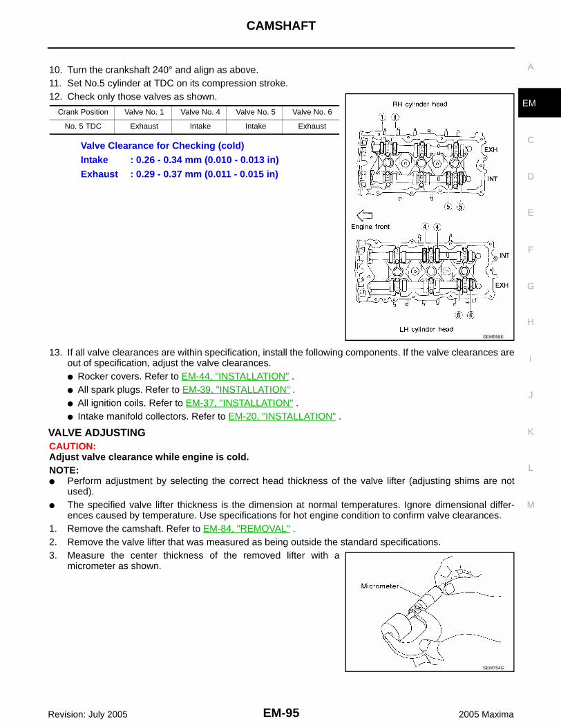
CAMSHAFT
EM-95
C
D
E
F
G
H
I
J
K
L
M
A
EM
Revision: July 2005 2005 Maxima
10. Turn the crankshaft 240° and align as above.11. Set No.5 cylinder at TDC on its compression stroke.12. Check only those valves as shown.
13. If all valve clearances are within specification, install the following components. If the valve clearances areout of specification, adjust the valve clearances.● Rocker covers. Refer to EM-44, "INSTALLATION" .● All spark plugs. Refer to EM-39, "INSTALLATION" .● All ignition coils. Refer to EM-37, "INSTALLATION" .● Intake manifold collectors. Refer to EM-20, "INSTALLATION" .
VALVE ADJUSTINGCAUTION:Adjust valve clearance while engine is cold.NOTE:● Perform adjustment by selecting the correct head thickness of the valve lifter (adjusting shims are not
used).● The specified valve lifter thickness is the dimension at normal temperatures. Ignore dimensional differ-
ences caused by temperature. Use specifications for hot engine condition to confirm valve clearances.1. Remove the camshaft. Refer to EM-84, "REMOVAL" .2. Remove the valve lifter that was measured as being outside the standard specifications.3. Measure the center thickness of the removed lifter with a
micrometer as shown.
Crank Position Valve No. 1 Valve No. 4 Valve No. 5 Valve No. 6
No. 5 TDC Exhaust Intake Intake Exhaust
Valve Clearance for Checking (cold)Intake : 0.26 - 0.34 mm (0.010 - 0.013 in)Exhaust : 0.29 - 0.37 mm (0.011 - 0.015 in)
SEM958E
SEM754G

EM-96Revision: July 2005
CAMSHAFT
2005 Maxima
4. Use the equation below to calculate the replacement valve lifterthickness.Valve lifter thickness calculation equation: t = t1 + (C1 - C2)t = thickness of the replacement liftert1 = thickness of the removed lifterC1 = measured valve clearanceC2 = standard valve clearance● The thickness of the new valve lifter can be identified by the
stamp mark on the reverse side (inside the lifter).● Available thickness of the valve lifter (factory setting):
7.88 - 8.40 mm (0.3102 - 0.3307 in), in 0.02 mm (0.0008 in)increments, in 27 sizes (intake / exhaust). Refer to EM-153,"Valve Lifter" .NOTE:Two types of stamp marks are used for parallel setting and for manufacturer identification.
5. Install the selected replacement valve lifter.6. Install the camshaft. Refer to EM-88, "INSTALLATION" .7. Rotate the crankshaft a few turns by hand.8. Confirm that the valve clearances are within specification.9. After the engine has been run to full operating temperature, confirm that the valve clearances are within
specification.
* Approximately 80°C (176°F)
Value lifter thicknessIntake : 0.30 mm (0.012 in)Exhaust : 0.33 mm (0.013 in)
SEM755G
Valve Clearance Cold Hot* (reference data)
Intake 0.26 - 0.34 mm (0.010 - 0.013 in) 0.304 - 0.416 mm (0.012 - 0.016 in)
Exhaust 0.29 - 0.37 mm (0.011 - 0.015 in) 0.308 - 0.432 mm (0.012 - 0.017 in)

OIL SEAL
EM-97
C
D
E
F
G
H
I
J
K
L
M
A
EM
Revision: July 2005 2005 Maxima
OIL SEAL PFP:00100
Removal and Installation of Valve Oil Seal EBS00JB0
REMOVAL1. Remove camshaft and valve lifter relating to valve oil seal to be removed. Refer to EM-83, "Removal and
Installation" .2. Rotate crankshaft, and set piston whose oil seal is to removed to top dead center. This prevents valve
from dropping inside cylinder.CAUTION:When rotating crankshaft, be careful to avoid scarring the front cover with the timing chain.
3. Remove valve collet, valve spring retainer and valve springusing Tool.
4. Remove valve oil seal using Tool.
INSTALLATION1. Apply new engine oil to new valve oil seal joint surface and seal lip.2. Press in valve oil seal to height "H" using Tool to specified
height.
NOTE:Dimension "H": height measured before valve spring seat instal-lation.
3. Installation of the remaining components is in the reverse orderof removal.
Removal and Installation of Front Oil Seal EBS00JB1
REMOVAL1. Remove the following parts:
● Engine undercover.● Drive belts. Refer to EM-12, "DRIVE BELTS" .● Radiator fan. Refer to CO-12, "REMOVAL" .
2. Remove the crankshaft pulley as follows: a. Remove the starter motor. Refer to SC-17, "M/T MODELS" or SC-18, "5-Speed A/T Models" .
Tool numbers : KV10116200 (J-26336-A): KV10115900 (J-26336-20): KV10109230 ( — )
PBIC1649E
Tool number : KV10107902 (J-38959)
WBIA0489E
Tool number : (J-39386)
Intake and exhaust : 14.3 - 14.9 mm (0.563 - 0.587 in)
WBIA0490E

EM-98Revision: July 2005
OIL SEAL
2005 Maxima
b. Install Tool as shown.
CAUTION:Do not damage the ring gear teeth, or the signal plate teethbehind the ring gear when setting the stopper.
c. Loosen crankshaft pulley bolt using pulley holder and locate boltseating surface at 10 mm (0.39 in) from its original position.
d. Position a pulley puller at recess hole of crankshaft pulley toremove crankshaft pulley.CAUTION:Do not use a puller claw on crankshaft pulley periphery.
3. Remove front oil seal from front timing chain case.CAUTION:Be careful not to damage front timing chain case or crank-shaft.
Tool number : KV10117700 (J-44716)
WBIA0270E
WBIA0271E
PBIC0885E
EMQ0477D
SEM829E

OIL SEAL
EM-99
C
D
E
F
G
H
I
J
K
L
M
A
EM
Revision: July 2005 2005 Maxima
INSTALLATION1. Apply new engine oil to new oil seal and install it flush with front
of mounting surface using a suitable tool.● Install new oil seal in the direction shown.
CAUTION:Press fit straight and avoid causing burrs or tilting the oilseal.
2. Install crankshaft pulley and tighten the bolt in two steps.● Lubricate thread and seat surface of the bolt with new engine
oil.● Apply a paint mark for the second step of angle tightening.
3. Remove Tool.
4. Installation of the remaining components is in reverse order of removal.
Removal and Installation of Rear Oil Seal EBS00JB2
REMOVAL1. Remove transaxle, refer to MT-16, "REMOVAL" (MT), AT-243, "REMOVAL" (5 AT).2. Remove flywheel or drive plate. Refer to EM-122, "Disassembly and Assembly"EM-123, "DISASSEM-
BLY" (M/T), EM-117, "REMOVAL"AT-243, "REMOVAL" (5 AT).
Suitable driftOuter diameter : 59 mm (2.32 in)Inner diameter : 49 mm (1.93 in)
SEM715A
Step 1 : 39 - 49 N·m (4.0 - 5.0 kg-m, 29 - 36 ft-lb)Step 2 : 84° - 90° degrees clockwise
Tool number : KV10112100 (BT-8653-A)
SEM531G
Tool number : KV10117700 (J-44716)
WBIA0270E
WBIA0271E
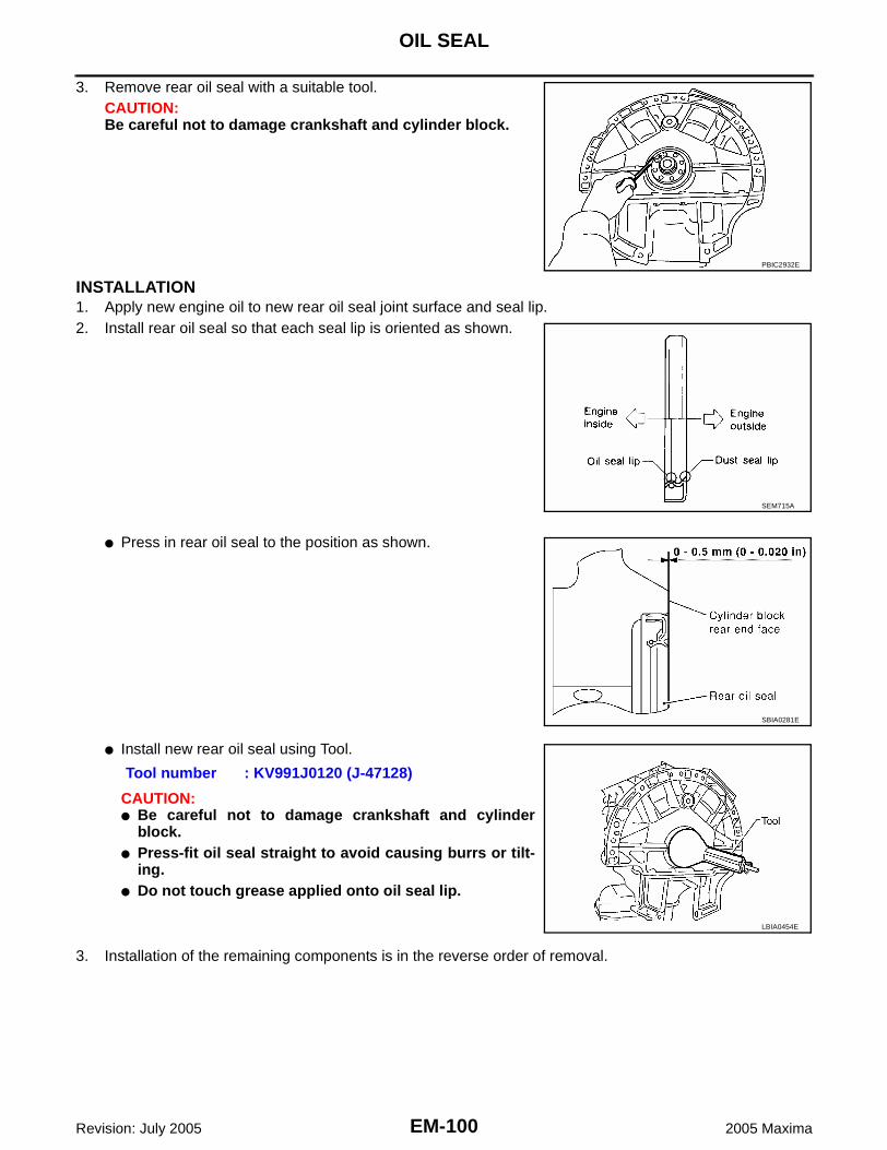
EM-100Revision: July 2005
OIL SEAL
2005 Maxima
3. Remove rear oil seal with a suitable tool.CAUTION:Be careful not to damage crankshaft and cylinder block.
INSTALLATION1. Apply new engine oil to new rear oil seal joint surface and seal lip.2. Install rear oil seal so that each seal lip is oriented as shown.
● Press in rear oil seal to the position as shown.
● Install new rear oil seal using Tool.
CAUTION:● Be careful not to damage crankshaft and cylinder
block.● Press-fit oil seal straight to avoid causing burrs or tilt-
ing.● Do not touch grease applied onto oil seal lip.
3. Installation of the remaining components is in the reverse order of removal.
PBIC2932E
SEM715A
SBIA0281E
Tool number : KV991J0120 (J-47128)
LBIA0454E

CYLINDER HEAD
EM-101
C
D
E
F
G
H
I
J
K
L
M
A
EM
Revision: July 2005 2005 Maxima
CYLINDER HEAD PFP:11041
On-Vehicle Service EBS00JB3
CHECKING COMPRESSION PRESSURE1. Run the engine until it reaches normal operating temperature.2. Turn the ignition switch to OFF.3. Release fuel pressure and leave the fuel pump electrically disconnected. Refer to EC-93, "FUEL PRES-
SURE RELEASE" .4. Remove all six spark plugs. Refer to EM-38, "Removal and Installation" .5. Attach a compression tester to No. 1 cylinder.6. Depress accelerator pedal fully to keep the electric throttle con-
trol actuator butterfly-valve wide open to maximize air intakeflow.
7. Crank the engine and record the highest gauge indication.8. Repeat the measurement on each cylinder (steps 5 - 7).
NOTE:Always use a fully-charged battery to obtain specified enginespeed.
Unit: kPa (kg/cm2 , psi)/300 rpm
9. If compression in one or more cylinders is low:a. Pour a small amount of engine oil into cylinders through the spark plug holes.b. Retest compression (steps 5 - 8).
● If adding oil helps raise compression pressure, then the piston rings may be worn or damaged. If so,replace piston rings after checking piston.
● If the pressure stays low, a valve may be sticking or is seating improperly. Inspect and repair the valveand/or valve seat. Refer to EM-152, "VALVE" . If the valve and/or valve seat is damaged excessively,replace as necessary.
● If compression stays low in two or more cylinders that are next to each other:– The cylinder head gasket may be leaking.– Both cylinders may have valve component damage. Inspect and repair as necessary.
10. After inspection is complete, install removed components.11. Start engine and confirm that engine runs smoothly.12. Perform trouble diagnosis. If DTC appears, erase it. Refer to EC-95, "TROUBLE DIAGNOSIS" .
Standard MinimumDifference limit between
cylinders
1,275 (13.0, 185) 981 (10.0, 142) 98 (1.0, 14)
SEM387C
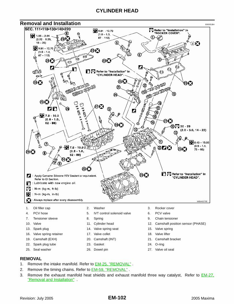
EM-102Revision: July 2005
CYLINDER HEAD
2005 Maxima
Removal and Installation EBS00JB4
REMOVAL1. Remove the intake manifold. Refer to EM-25, "REMOVAL" . 2. Remove the timing chains. Refer to EM-59, "REMOVAL" .3. Remove the exhaust manifold heat shields and exhaust manifold three way catalyst, Refer to EM-27,
"Removal and Installation" .
WBIA0275E
1. Oil filler cap 2. Washer 3. Rocker cover
4. PCV hose 5. IVT control solenoid valve 6. PCV valve
7. Tensioner sleeve 8. Spring 9. Chain tensioner
10. Valve 11. Cylinder head 12. Camshaft position sensor (PHASE)
13. Spark plug 14. Valve spring seat 15. Valve spring
16. Valve spring retainer 17. Valve collet 18. Valve lifter
19. Camshaft (EXH) 20. Camshaft (INT) 21. Camshaft bracket
22. Spark plug tube 23. Gasket 24. O-ring
25. Seal washer 26. Dowel pin 27. Valve oil seal

CYLINDER HEAD
EM-103
C
D
E
F
G
H
I
J
K
L
M
A
EM
Revision: July 2005 2005 Maxima
4. Remove the intake and exhaust camshafts and the camshaftbrackets.● Mark the camshaft brackets so they are placed in the same
position and direction for installation.● Equally loosen the camshaft bracket bolts in several steps in
the order shown.
5. Remove the water outlet. Refer to CO-26, "REMOVAL" .6. Remove the RH and LH cylinder head bolts, using power tool.
● The bolts should be loosened gradually in three steps in theorder shown.
7. Remove cylinder heads and gaskets.● Discard the cylinder head gaskets and use new gaskets for
installation.
SEM856E
SEM857E
SEM859E
SEM860E
SEM863E

EM-104Revision: July 2005
CYLINDER HEAD
2005 Maxima
INSPECTION AFTER REMOVALOuter Diameter of Cylinder Head Bolts● Inspect the cylinder head bolts before installing the cylinder heads.
CAUTION:Cylinder head bolts are tightened by degree rotation tight-ening method. Whenever the size difference between d1and d2 exceeds the limit, replace the bolts with new ones.
● If a reduction in outer diameter appears in a position other thand2, use it as the d2 measuring point.
● Lubricate threads and seat surfaces of the bolts with new engineoil for installation.
INSTALLATION1. Before installing the rear timing chain case, remove the old Sili-
cone RTV Sealant from mating surface using a scraper.● Also remove old sealant from mating surface of cylinder
block.
● Remove the old Silicone RTV Sealant from the bolt hole andthread.
2. Before installing the No. 1 camshaft bracket, remove the old Sil-icone RTV Sealant from the mating surface using a scraper.● Do not scratch the mating surface.
Limit (d1 - d2) : 0.11 mm (0.0043 in)
SEM957E
SEM891E
SEM161F
SEM892E

CYLINDER HEAD
EM-105
C
D
E
F
G
H
I
J
K
L
M
A
EM
Revision: July 2005 2005 Maxima
3. Turn the crankshaft until No. 1 piston is set at TDC on the com-pression stroke.● The crankshaft key should line up with the right bank cylinder
center line as shown.
4. Install new gaskets on the cylinder heads.CAUTION:Do not rotate crankshaft and camshaft separately or valveswill strike piston heads.
5. Install the cylinder heads on the cylinder block. Tighten the cylin-der head bolts in five steps in the order shown.
SEM532G
SEM445G
Step a : 98 N·m (10 kg-m, 72 ft-lb) Step b : 0 N·m Loosen in the reverse order of tightening.Step c : 39.2 N·m (4.0 kg-m, 29 ft-lb)Step d : 90° degrees clockwiseStep e : 90° degrees clockwise
SEM879EA
SEM877EA
SEM878EA

EM-106Revision: July 2005
CYLINDER HEAD
2005 Maxima
6. Install the water outlet. Refer to CO-26, "INSTALLATION" .7. Install camshaft chain tensioners on both sides of cylinder head.
8. Install exhaust and intake camshafts and camshaft brackets.● Intake camshaft has a drill mark on camshaft sprocket mount-
ing flange.
● Follow your identification marks made during removal, or fol-low the identification marks that are present on the new cam-shaft components for proper placement.
● Position the camshafts:RH exhaust camshaft dowel pin at about 10 o'clockLH exhaust camshaft dowel pin at about 2 o'clock.
Camshaft chain tensioner bolts
: 7 - 10 N·m (0.8 - 1.0 kg-m, 62 - 88 in-lb)
SEM444G
SEM652F
Bank INT/EXH ID mark Drill markPaint marks
M1 M2
RHINT RE Yes Yes No
EXH RE No No Yes
LHINT LH Yes Yes No
EXH LH No No Yes SEM653F
KBIA1072E

CYLINDER HEAD
EM-107
C
D
E
F
G
H
I
J
K
L
M
A
EM
Revision: July 2005 2005 Maxima
9. Before installing No. 1 camshaft bracket, apply sealant to matingsurface.● Use Genuine Silicone RTV Sealant, or equivalent. Refer to
GI-43, "RECOMMENDED CHEMICAL PRODUCTS ANDSEALANTS" .
● Before installation, wipe off any protruding sealant.● Refer to CO-2, "LIQUID GASKET APPLICATION PROCE-
DURE" .
● Install camshaft brackets in their original positions and direc-tions. Align the stamp marks as shown.
● If any part of the valve assembly or camshaft is replaced,check and adjust the valve clearance. Refer to EM-93, "ValveClearance" .
SEM446G
WBIA0266E
SEM564G

EM-108Revision: July 2005
CYLINDER HEAD
2005 Maxima
10. Tighten the camshaft bracket bolts in five steps in the ordershown.NOTE:Lubricate the threads and seat surfaces of the camshaft bracketbolts with new engine oil before installation.
11. Install the IVT control solenoid valves with new gaskets.
12. Install the new O-rings on the cylinder block.
13. Install the new O-rings on the cylinder head.
Camshaft bracket boltsStep 1 (bolts 7 - 10) : 1.96 N·m (0.2 kg-m, 17 in-lb)Step 2 (bolts 1 - 6) : 1.96 N·m (0.2 kg-m, 17 in-lb)Step 3 : 5.88 N·m (0.6 kg-m, 52 in-lb)Step 4 (bolts 1 - 6) : 10.4 N·m (1.1 kg-m, 92 in-lb)
SEM885EA
SEM886EA
IVT control solenoid valve bolts
: 10 - 12 N·m (1.0 - 1.3 kg-m, 87 - 112 in-lb)
WBIA0169E
SEM534G
SEM447G

CYLINDER HEAD
EM-109
C
D
E
F
G
H
I
J
K
L
M
A
EM
Revision: July 2005 2005 Maxima
14. Install the exhaust manifold three way catalysts (manifolds) and exhaust manifold heat shields. Refer toEM-27, "Removal and Installation" .
15. Install timing chain. Refer to EM-58, "Removal and Installation" .16. Install the intake manifold. Refer to EM-26, "INSTALLATION" .

EM-110Revision: July 2005
CYLINDER HEAD
2005 Maxima
Disassembly and Assembly EBS00JB5
WBIA0216E
1. Cylinder head (right bank) 2. Spark plug 3. Valve lifter
4. Valve collet 5. Valve spring retainer 6. Valve spring
7. Valve oil seal 8. Valve guide 9. Valve seat (INT)
10. Valve (INT) 11. Valve (EXH) 12. Valve seat (EXH)
13. Cylinder head (left bank) 14. Intake manifold 15. Valve spring seat
16. Spark plug tube

CYLINDER HEAD
EM-111
C
D
E
F
G
H
I
J
K
L
M
A
EM
Revision: July 2005 2005 Maxima
CAUTION:● When installing camshafts, chain tensioners, oil seals, or other sliding parts, lubricate contacting
surfaces with new engine oil.● Apply new engine oil to threads and seat surface when installing cylinder head, camshaft
sprocket, crankshaft pulley, and camshaft bracket.● Attach tags to valve lifters so as not to mix them up.
DISASSEMBLY1. Remove valve lifter.
● Mark position for installation.2. Remove valve collet.
● Compress valve spring using Tool. Remove valve collet withmagnet driver.
3. Remove valve spring retainer, valve spring, and valve springseat.
4. Push valve stem to combustion chamber side, and removevalve, mark for assembly. ● Inspect valve guide clearance before removal. Refer to EM-112, "VALVE GUIDE CLEARANCE" .● Confirm installation point.
5. Remove the valve oil seals using Tool.
6. If valve seat must be replaced, refer to EM-114, "VALVE SEATREPLACEMENT" .
7. If valve guide must be replaced, refer to EM-113, "VALVEGUIDE REPLACEMENT" .
8. Remove spark plug with spark plug wrench.9. Remove spark plug tube, as necessary.
● Using a pair of pliers, pull spark plug tube out of cylinderhead.
CAUTION:● Be careful not to damage cylinder head.● Once removed, a spark plug tube will be deformed and cannot be reused. Do not remove it
unless absolutely necessary.
Tool numbers : KV10116200 (J26336-B): KV10115900 (J26336-20): KV10109230 ( – )
Tool number : KV10107902 (J38959)
PBIC1649E
PBIC0884E

EM-112Revision: July 2005
CYLINDER HEAD
2005 Maxima
Inspection After Disassembly EBS00JB6
CYLINDER HEAD DISTORTION● Clean the surface of the cylinder head. Use a reliable straightedge and feeler gauge to check the flatness
of cylinder head surface.● Check along six positions as shown.
● If beyond the specified limit, resurface or replace it.● The limit for cylinder head resurfacing is determined by the cylin-
der block resurfacing.
● After resurfacing cylinder head, check that camshaft rotatesfreely by hand. If resistance is felt, cylinder head must bereplaced.
VALVE DIMENSIONSCheck dimensions of each valve, refer to EM-152, "Valve Dimen-sions" .
VALVE GUIDE CLEARANCE1. Measure valve deflection as shown in the figure. (Valve and
valve guide mostly wear in this direction.)
Head surface distortionLimit : 0.1 mm (0.004 in)
Resurfacing LimitAmount of cylinder head resurfacing is “A”.Amount of cylinder block resurfacing is “B”.The maximum limit : A + B = 0.2 mm (0.008 in)
Nominal cylinder head height "H"
: 126.3 - 126.5 mm (4.972 - 4.980 in)
SEM861E
PBIC0924E
SEM188A
Valve deflection limit (dial gauge reading)Intake : 0.24 mm (0.0094 in)Exhaust : 0.28 mm (0.0110 in)
SEM178F

CYLINDER HEAD
EM-113
C
D
E
F
G
H
I
J
K
L
M
A
EM
Revision: July 2005 2005 Maxima
2. If it exceeds the limit, check valve to valve guide clearance.a. Measure valve stem diameter and valve guide inner diameter.b. Check that clearance is within specification.
c. If it exceeds the limit, replace valve or valve guide.
VALVE GUIDE REPLACEMENTWhen valve guide is removed, replace with oversized [0.2 mm (0.008 in)] valve guide.1. To remove valve guide, heat cylinder head to 110° - 130°C (230°
- 266°F) by soaking in heated oil.
2. Drive out the valve guide with a press [under a 20 kN (2.2 USton) pressure] or hammer and suitable tool.WARNING:Cylinder head is hot. Wear protective equipment to preventgetting burned.
3. Ream cylinder head valve guide hole.
Valve to valve guide clearance standardIntake : 0.020 - 0.053 mm (0.0008 - 0.0021 in)Exhaust : 0.030 - 0.063 mm (0.0012 - 0.0025 in)Valve to valve guide clearance limitIntake : 0.08 mm (0.0031 in)Exhaust : 0.09 mm (0.004 in) SEM938C
SEM008A
SEM931C
Valve guide hole diame-ter (for service parts), intake and exhaust
: 10.175 - 10.196 mm (0.4006 - 0.4014 in)
SEM932C

EM-114Revision: July 2005
CYLINDER HEAD
2005 Maxima
4. Heat cylinder head to 110° - 130°C (230° - 266°F) by soaking inheated oil and press new valve guide from camshaft side intothe cylinder head to the dimensions as shown.
5. Using a valve guide reamer, apply a reamer finish to the valveguide.
VALVE SEAT CONTACT● After confirming that the dimensions of valve guides and valves
are within specifications, perform this procedure. ● Apply prussian blue onto contacting surface of valve seat to
check the condition of the valve contact on the surface.● Check if the contact area band is continuous all around the cir-
cumference.● If not, grind to adjust valve fitting and check again. If the contact-
ing surface still has N.G conditions even after the re-check,replace valve seat.
VALVE SEAT REPLACEMENT1. Bore out old seat until it collapses. Boring should not continue
beyond the bottom face of the seat recess in cylinder head. Setthe machine depth stop to ensure this.
2. Ream cylinder head recess for service valve seat.
● Be sure to ream in circles concentric to the valve guide center.● This will enable valve seat to fit correctly.
3. Heat cylinder head to 110° - 130°C (230° - 266°F) by soaking inheated oil.
4. Press fit valve seat until it seats on the bottom.5. Cut or grind valve seat using suitable tool to the specified dimensions. Refer to EM-152, "VALVE" .6. After cutting, lap valve seat with abrasive compound.7. Check valve seating condition.
Projection "L" : 12.6 - 12.8 mm (0.496 - 0.504 in)
SEM950E
Intake and exhaust finished size
: 6.000 - 6.018 mm(0.2362 - 0.2369 in)
SEM932C
SBIA0322E
Oversize : 0.5 mm (0.020 in)Intake : 38.500 - 38.516 mm (1.5157 - 1.5164 in)Exhaust : 32.700 - 32.716 mm (1.2874 - 1.2880 in)
SEM795A

CYLINDER HEAD
EM-115
C
D
E
F
G
H
I
J
K
L
M
A
EM
Revision: July 2005 2005 Maxima
8. Use a depth gauge to measure the distance between the mount-ing surface of the cylinder head spring seat and the valve stemend. If the distance is shorter than specified, repeat step 5 toadjust it. If it is longer, replace the valve seat with a new one.
VALVE SPRING SQUARENESSSet try square along the side of valve spring and rotate the spring.Measure the maximum clearance between the top face of spring andtry square.
VALVE SPRING DIMENSIONS AND VALVE SPRING PRESSURE LOADCheck valve spring pressure at specified spring height.
If it is not within specifications, replace the spring.
ASSEMBLY1. Install valve guide. Refer to EM-113, "VALVE GUIDE REPLACEMENT" .2. Install valve seat. Refer to EM-114, "VALVE SEAT REPLACEMENT" .
Seat face angle “α” : 45° ± 0° 15' degrees/minutes
Contacting width “W” for intake : 1.2 ± 0.11 mm (0.0429 - 0.0516 in)
Contacting width “W” for exhaust : 1.4 ± 0.11 mm (0.0508 - 0.0594 in)
SEM892B
Valve seat resurface limit “L” intake
: 41.07 - 41.67 mm (1.6169 - 1.6405 in)
Valve seat resurface limit “L” exhaust
: 41.00 - 41.60 mm (1.6142 - 1.6378 in)
SEM621F
Out-of-square limit : Less than 2.0 mm (0.079 in)
PBIC0080E
Free height : 46.90 mm (1.8465 in)Standard : 166 - 188 N (16.9 - 19.2 kg, 37.3 - 42.3 lb)
at height 37.0 mm (1.457 in)Limit : 378 - 426 N (38.6 - 43.5 kg, 85.0 - 95.8 lb)
at height 27.8 mm (1.094 in)
SEM113

EM-116Revision: July 2005
CYLINDER HEAD
2005 Maxima
3. Install new valve spring seats and new valve oil seals using Tool.
● Install with valve oil seal drift to match dimension in illustra-tion.
NOTE:Dimension "H": Height measured before valve spring seat instal-lation.
4. Install the valves in their original position, as marked during dis-assembly.
5. Install valve spring (uneven pitch type).● Install smaller pitch end (paint mark) to cylinder head side
(valve spring seat side).6. Install valve spring retainer.
7. Install valve collet.
● Compress valve spring using Tool and install valve collet.● Tap stem edge lightly with plastic hammer after installation to
check its installed condition.8. Install valve lifter refer to EM-95, "VALVE ADJUSTING" for
proper valve lifter selection.
9. Install spark plug tube as follows:a. Remove old liquid gasket from cylinder head mounting hole.b. Apply liquid gasket to area within approximately 12 mm (0.47 in)
from edge of spark plug tube press fit side.● Use Genuine RTV Silicone Sealant or equivalent. Refer to GI-
43, "RECOMMENDED CHEMICAL PRODUCTS AND SEAL-ANTS" .
c. Using a drift, press fit the spark plug tube so that it height "H" isas specified.
CAUTION:● When press fitting, take care not to deform spark plug tube.● After press fitting, wipe off liquid gasket protruding onto cylinder head upper face.
10. Install spark plug with spark plug wrench.
Tool number : (J39386)
Height "H"Intake and exhaust : 14.3 - 14.9 mm (0.563 - 0.587 in) PBIC0802E
SEM085D
Tool numbers : KV10116200 (J26336-B): KV10115900 (J26336-20): KV10109230 ( – )
PBIC1649E
Standard press fit height "H"
:38.55 - 38.65 mm (1.5177 - 1.5217 in)
Spark plug : 20 - 29 N·m (2.0 - 3.0 kg-m, 14 - 22 ft-lb)
KBIA1248E

ENGINE ASSEMBLY
EM-117
C
D
E
F
G
H
I
J
K
L
M
A
EM
Revision: July 2005 2005 Maxima
ENGINE ASSEMBLY PFP:10001
Removal and Installation EBS00JB7
WARNING:● Place chocks at front and back of rear wheels.● For engines not equipped with engine slingers, attach proper slingers and bolts as described in
the NISSAN Parts Catalog.CAUTION:● Do not start working until exhaust system and coolant are cool.● If items or work required are not covered by the engine main body section, refer to the applicable
sections.● Use the correct supporting points for lifting and jacking. Refer to GI-38, "LIFTING POINT" .● In removing the drive shafts, be careful not to damage any transaxle grease seals.● Before separating the engine and transaxle, remove the crankshaft position sensor (POS).● Do not damage the edge of the crankshaft position sensor (POS) or the ring gear teeth.
REMOVAL1. Drain coolant. Refer to MA-14, "DRAINING ENGINE COOLANT" .2. Remove the front cowl grille. Refer to EI-19, "Removal and Installation" .3. Remove the windshield wiper assembly. Refer to WW-23, "Removal and Installation of Wiper Motor and
Linkage" .
LBIA0360E
1. Rear engine mounting bracket 2. RH engine mounting insulator 3. RH engine mount
4. Front engine mount 5. Stopper 6. Front engine mounting insulator
7. LH transaxle mount 8. LH transaxle mounting insulator 9. Air guide (A/T only)
10. Rear engine mounting insulator

EM-118Revision: July 2005
ENGINE ASSEMBLY
2005 Maxima
4. Disconnect engine room harness from the engine side and position it aside. Disconnect engine harnessground connections. Access the connector through the glove box opening. Refer to IP-10, "INSTRUMENTPANEL ASSEMBLY" .
5. Remove the hood. Refer to BL-13, "Removal and Installation of Hood Assembly" .6. Remove the battery and battery tray. Refer to SC-9, "Removal and Installation" .7. Remove the engine cover using power tool. Remove side engine covers.8. Disconnect the mass air flow sensor electrical connector. 9. Remove the fresh air intake tube and air cleaner to electric throttle control actuator tube attached to air
cleaner lid. Refer to EM-16, "Removal and Installation" .10. Disconnect two connectors below mass air flow sensor attached to the shock tower. 11. Release fuel pressure. Refer to EC-93, "FUEL PRESSURE RELEASE" .12. Disconnect fuel hose quick connection at vehicle piping side. Refer to EM-40, "Removal and Installation" .13. Remove and position aside the IPDM E/R and bracket and position aside. Refer to PG-27, "Removal and
Installation of IPDM E/R" .14. Remove the radiator assembly, coolant reservoir, and system hoses. Refer to CO-12, "REMOVAL" .15. Disconnect the power brake booster vacuum hose from the back of the intake manifold collector.16. Disconnect heater hoses at the cowl.17. Disconnect the two fusible link connectors at the battery positive terminal.18. Disconnect the harness retainers and position the engine harness aside.19. Remove the ground cable.20. Remove the clutch operating cylinder with lines attached and position aside. Refer to CL-11, "Removal
and Installation" .21. Drain engine oil. Refer to MA-16, "Changing Engine Oil" .22. Drain A/T oil. Refer to MA-22, "Changing A/T Fluid" .23. Drain M/T oil. Refer to MA-21, "Changing M/T Oil" .24. Disconnect the transaxle shift controls. Refer to AT-231, "SHIFT CONTROL SYSTEM" (5 A/T).25. Disconnect the transmission electrical connectors, harness retainers and position harness aside.26. Remove exhaust system refer to EX-5, "REMOVAL" .27. Remove RH splash shield.28. Remove the front wheel and tires.29. Remove the drive belts. Refer to EM-15, "Removal and Installation" .30. Remove the front exhaust tube and hanger using power tools. Refer to EX-3, "Removal and Installation" .31. Remove engine oil cooler pipe bolts.32. Remove the idler pulley and idler bracket.33. Remove the engine undercover.34. Remove the A/C compressor using power tools. Discharge and recover the R134a refrigerant. Refer to
ATC-119, "HFC-134a (R-134a) Service Procedure" .35. Remove the front drive shafts. Refer to FAX-11, "Removal and Installation" .36. Remove the front suspension member. Refer to FSU-15, "Removal and Installation" .
CAUTION:Make sure to disconnect electrically controlled engine mounting insulator harness clips andpower steering line mounts from the front suspension member prior to removal.
37. Disconnect the power steering pressure switch.38. Remove the power steering pump, without disconnecting the piping, from the engine and position and
secure it aside. Refer to PS-26, "REMOVAL" .

ENGINE ASSEMBLY
EM-119
C
D
E
F
G
H
I
J
K
L
M
A
EM
Revision: July 2005 2005 Maxima
39. Install engine slingers into front of left bank cylinder head andrear of right bank cylinder head.
40. Secure a hoist to the engine slingers.41. Remove the LH transaxle mount through bolt.42. Remove the RH engine mounting insulator nuts and bolt.43. Carefully lower the engine and transaxle assembly with the hoist avoiding interference with the vehicle
body.CAUTION:● Before and during this procedure, always check if any harnesses are left connected.● Avoid any damage to, or any oil/grease smearing or spills onto the engine mounting insulators.
44. Remove the crankshaft position sensor (POS).45. Remove rear cover plate and bolts securing the torque converter to the drive plate.46. Remove the starter motor. Refer to SC-17, "M/T MODELS" , SC-18, "5-Speed A/T Models" .47. Separate the engine and transaxle and mount the engine on a suitable engine stand.
Engine slinger bolts : 24.5 - 31.4 N·m (2.5 - 3.2 kg-m, 18 - 23 ft-lb)
SEM807G
SEM808G

EM-120Revision: July 2005
ENGINE ASSEMBLY
2005 Maxima
INSTALLATIONInstallation is in the reverse order of removal.
Manual Transaxle CAUTION:When installing the transaxle, do not allow the transaxle input shaft to contact the clutch cover.● When installing the transaxle to the engine, use the specified tightening torque in the order shown.
5 A/T ● When installing the transaxle to the engine, use the specified tightening torque in the numerical sequence
as shown.
● After installation, check the transaxle oil level, and check for any leaks and any loose mechanisms.● Install crankshaft position sensor (POS).
Bolt No. 1 2 3 4 5 6 7 8 9
Tightening torqueN·m (kg-m, ft-lb)
70 - 79 (7.1 - 8.1, 52 - 58) 36 - 47 (3.7 - 4.7, 27 - 34)
LBIA0354E
Bolt No. 1 2 3 4 5 6 7 8 9
Tightening torqueN·m (kg-m, ft-lb)
70 - 79 (7.1 - 8.1, 52 - 58) 36 - 47 (3.7 - 4.7, 27 - 34)
LBIA0355E

ENGINE ASSEMBLY
EM-121
C
D
E
F
G
H
I
J
K
L
M
A
EM
Revision: July 2005 2005 Maxima
● Install idler pulley.
INSPECTION AFTER INSTALLATION● Before starting engine, check oil/fluid levels including engine coolant and engine oil. If less than required
quantity, fill to the specified level. Refer to MA-9, "RECOMMENDED FLUIDS AND LUBRICANTS" .● Use procedure below to check for fuel leakage.● Turn ignition switch ON (with engine stopped). With fuel pressure applied to fuel piping, check for fuel
leakage at connection points.● Start engine. With engine speed increased, check again for fuel leakage at connection points.● Run engine to check for unusual noise and vibration.● Warm up engine thoroughly to make sure there is no leakage of Fuel, exhaust gas, or any oils/fluids
including engine oil and engine coolant.● Bleed air from passages in lines and hoses, such as in cooling system.● After cooling down engine, again check oil/fluid levels including engine oil and engine coolant. Refill to
specified level, if necessary.● Summary of the inspection items:
*Transmission/transaxle/CVT fluid, power steering fluid, brake fluid, etc.
Crankshaft position sensor (POS) bolt : 8.4 - 10.8 N·m (0.86 - 0.98 kg-m, 74.6 - 95.5 in-lb)
Idler pulley bolts : 25 - 31 N·m (2.5 - 3.2 kg-m, 18 - 23 ft-lb)
Item Before starting engine Engine running After engine stopped
Engine coolant Level Leakage Level
Engine oil Level Leakage Level
Other oils and fluids* Level Leakage Level
Fuel Leakage Leakage Leakage
Exhaust gas — Leakage —

EM-122Revision: July 2005
CYLINDER BLOCK
2005 Maxima
CYLINDER BLOCK PFP:11010
Disassembly and Assembly EBS00JB8
WBIA0273E
1. Rear oil seal retainer 2. Cylinder block 3. Knock sensor
4. Upper main bearing 5. Lower main bearing 6. Water drain plug (LH side)
7. Water connector (RH side) 8. Water drain plug (water pump side) 9. Main bearing cap
10. Main bearing beam 11. Crankshaft 12. Pilot bushing or pilot converter
13. Flywheel with signal plate (M/T) 14. Drive plate with signal plate (A/T) 15. Drive plate reinforcement
16. Oil ring set 17. Piston pin 18. Connecting rod bearing
19. Connecting rod 20. Piston 21. Top ring
22. Second ring 23. Cylinder block heater (Canada only) 24. Oil jet
25. Key 26. Snap ring 27. Baffle plate
28. Gasket

CYLINDER BLOCK
EM-123
C
D
E
F
G
H
I
J
K
L
M
A
EM
Revision: July 2005 2005 Maxima
CAUTION:● Apply new engine oil to parts as marked in illustrations before installation.● Place removed parts such as bearings and bearing caps in their proper order and direction.● When installing the connecting rod nuts, and main bearing cap bolts, apply new engine oil to the
threads and mating surfaces● Do not allow any magnetic materials to contact the signal plate teeth on the drive plate.
DISASSEMBLY1. Remove the engine assembly. Refer to EM-117, "ENGINE ASSEMBLY" .2. Install Tools to the right side of cylinder block.
Use the spacer on the engine rear side.
3. Lift engine and mount it on Tool.
● A commercial engine stand can be used.CAUTION:Use an engine stand that has a load capacity of approxi-mately 220kg (441 lb) or more.NOTE:This example is an engine stand for holding at the transaxlemounting side with the drive plate removed.
Tool numbers : KV10117001 ( – ): KV10106500 ( – )
PBIC0920E
Tool numbers : KV10117001 ( – ): KV10106500 ( – ): ST0501S000 ( – )
PBIC0805E
PBIC0085E
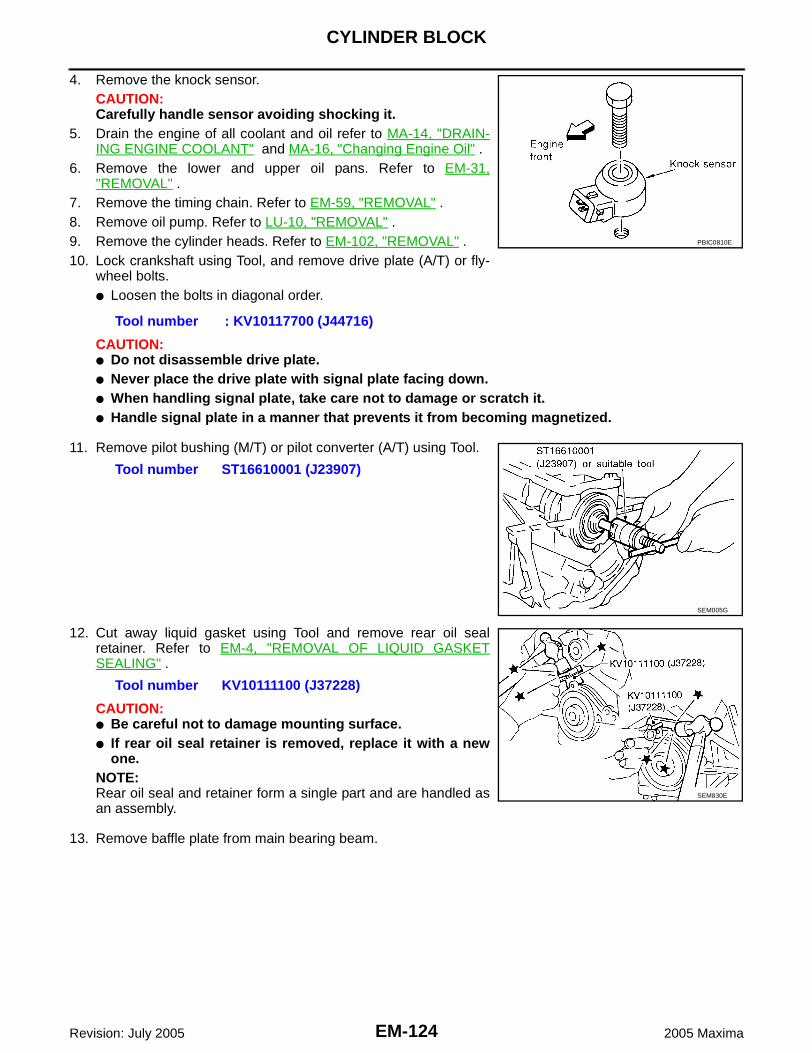
EM-124Revision: July 2005
CYLINDER BLOCK
2005 Maxima
4. Remove the knock sensor.CAUTION:Carefully handle sensor avoiding shocking it.
5. Drain the engine of all coolant and oil refer to MA-14, "DRAIN-ING ENGINE COOLANT" and MA-16, "Changing Engine Oil" .
6. Remove the lower and upper oil pans. Refer to EM-31,"REMOVAL" .
7. Remove the timing chain. Refer to EM-59, "REMOVAL" .8. Remove oil pump. Refer to LU-10, "REMOVAL" .9. Remove the cylinder heads. Refer to EM-102, "REMOVAL" .10. Lock crankshaft using Tool, and remove drive plate (A/T) or fly-
wheel bolts.● Loosen the bolts in diagonal order.
CAUTION:● Do not disassemble drive plate.● Never place the drive plate with signal plate facing down.● When handling signal plate, take care not to damage or scratch it.● Handle signal plate in a manner that prevents it from becoming magnetized.
11. Remove pilot bushing (M/T) or pilot converter (A/T) using Tool.
12. Cut away liquid gasket using Tool and remove rear oil sealretainer. Refer to EM-4, "REMOVAL OF LIQUID GASKETSEALING" .
CAUTION:● Be careful not to damage mounting surface.● If rear oil seal retainer is removed, replace it with a new
one.NOTE:Rear oil seal and retainer form a single part and are handled asan assembly.
13. Remove baffle plate from main bearing beam.
Tool number : KV10117700 (J44716)
PBIC0810E
Tool number ST16610001 (J23907)
SEM005G
Tool number KV10111100 (J37228)
SEM830E

CYLINDER BLOCK
EM-125
C
D
E
F
G
H
I
J
K
L
M
A
EM
Revision: July 2005 2005 Maxima
14. Remove the piston and connecting rod assemblies.a. Position the crankshaft pin corresponding to the connecting rod
to be removed onto the bottom dead center. b. Remove the connecting rod cap. c. Using a hammer handle or similar tool, push the piston and con-
necting rod assembly out to the cylinder head side. ● Before removing the piston and connecting rod assembly,
check the connecting rod side clearance. Refer to EM-158,"CONNECTING ROD" .
15. Remove the connecting rod bearings. CAUTION:● When removing the connecting rod side bearings, note the installation position. Keep them in
the correct order.16. Remove the piston rings and oil rings from the piston.
● Use a piston ring expander.● Before removing the piston rings and oil rings, check the pis-
ton ring side clearance. Refer to EM-140, "PISTON RINGSIDE CLEARANCE" .
CAUTION:● When removing the piston rings, be careful not to dam-
age the piston. Do not expand the rings excessively.● Be careful to mark the rings if they are to be reused so
they are installed in their original position.
17. Remove the piston from the connecting rod as follows. a. Using a snap ring pliers, remove the snap ring.
b. Heat the pistons to 60° - 70°C (140° - 158°F).
PBIC0086E
PBIC0087E
PBIC0088E
SEM965A

EM-126Revision: July 2005
CYLINDER BLOCK
2005 Maxima
c. Push out the piston pin with a suitable tool, with an outer diame-ter approximately 20 mm (0.8 in).
18. Loosen the main bearing cap bolts in the order shown andremove the main bearing beam, bearing caps and crankshaft. ● Before loosening the main bearing cap bolts, measure the
crankshaft side clearance. Refer to EM-145, "OUT-OF-ROUND AND TAPER OF CRANKSHAFT" .
19. Remove the oil jets.20. Remove the main bearings and thrust bearings from the cylinder
block and main bearing caps.CAUTION:When removing them, note their direction and position.Keep them in the correct order for installation.
ASSEMBLY1. Blow out the coolant and oil passages and cylinder bore to remove any foreign materials.
WARNING:Use goggles to protect your eyes.
2. Apply liquid gasket and install each water drain plug into the cylinder block.● Install the cylinder block heater, if equipped.● Use Genuine Silicone RTV Sealant or equivalent. Refer to GI-43, "RECOMMENDED CHEMICAL
PRODUCTS AND SEALANTS" .3. Install the oil jets.
● Insert the oil jet dowel pin into the cylinder block dowel pinhole, and tighten the oil jet bolts.
EMM0072D
SEM842E
PBIC0898E
Oil jet bolts : 23.6 - 30.4 N·m (2.4 - 3.1 kg-m, 18 - 22 ft-lb)
PBIC0898E

CYLINDER BLOCK
EM-127
C
D
E
F
G
H
I
J
K
L
M
A
EM
Revision: July 2005 2005 Maxima
4. Install the main bearings and the thrust bearings.a. Remove dust, dirt, and oil on the bearing mating surfaces of the
cylinder block and the main bearing cap.b. Install the thrust bearings to both sides of the No. 3 journal hous-
ing on the cylinder block and the main bearing cap.● Install the thrust bearings with the oil groove facing the crank-
shaft arm (outside).● Install bearing with a projection on one end on cylinder block
and bearing with a projection at center on cap. Align each pro-jection with mating notch.
5. Set the upper main bearings in their proper positions on the cyl-inder block.● Confirm the correct main bearings are used. Refer to EM-143,
"PISTON-TO-CYLINDER BORE CLEARANCE" .
6. Check specifications for the re-use of the main bearing capbolts.● Measure d1 and d2 as shown. ● For d2, select the minimum diameter in the measuring area.● If the difference between d1 and d2 exceeds the limit, replace
the bolts for assembly.
7. After installing the crankshaft, lower main bearings, main bearing caps, main bearing beam, and bearingcap bolts.
a. Make sure that the front marks on the main bearing beam facesthe front of the engine.
b. Prior to tightening all the bearing cap bolts, place the bearingbeam in its proper position by shifting the crankshaft in the axialposition.
c. After tightening the bearing cap bolts, make sure the crankshaftturns smoothly.
d. Lubricate the threads and seat surfaces of the bolts with newengine oil.
PBIC0807E
SEM175F
Limit (d1 - d2) : 0.11 mm (0.0043 in)
SEM177F
SEM456G

EM-128Revision: July 2005
CYLINDER BLOCK
2005 Maxima
e. Tighten the bearing cap bolts in two steps in the order shown:
CAUTION:Measure the tighten angle with an angle wrench. Do notmeasure visually.
8. Using a dial indicator, measure the clearance between the thrustbearings and the connecting rods when the crankshaft is movedfrom front to rear.
● If beyond the limit, replace the thrust bearings and measureagain. If still beyond the limit, replace the crankshaft.
9. Install the rear oil seal retainer.● Apply sealant to rear oil seal retainer using Tool as shown.
● Use Genuine Silicone RTV Sealant, or equivalent. Refer toGI-43, "RECOMMENDED CHEMICAL PRODUCTS ANDSEALANTS" .
CAUTION:Rear oil seal is replaced with the rear oil seal retainer andmust be replaced as an assembly.
Bearing cap boltsStep 1 : 32 - 38 N·m (3.3 - 3.9 kg-m, 24 - 28 ft-lb)Step 2 : 90° - 95° degrees clockwise
SEM851E
PBIC0096E
Standard : 0.10 - 0.25 mm (0.0039 - 0.0098 in)Limit : 0.30 mm (0.0118 in)
SEM852E
Tool number : WS39930000 ( – )
Rear oil seal retainer bolts
: 8.2 - 9.3 N·m (0.83 - 0.95 kg-m, 72 - 82 in-lb)
PBIC0922E

CYLINDER BLOCK
EM-129
C
D
E
F
G
H
I
J
K
L
M
A
EM
Revision: July 2005 2005 Maxima
10. Install the piston to the connecting rod. a. Using suitable snap ring pliers, install the snap ring into the pin-
groove of the piston rear side. ● Insert it fully into groove to install.
b. Install the piston to the connecting rod.● Heat the piston until the piston pin can be pushed in by hand
without excess force [approx. 60° - 70°C (140° to 158°F)].From the front to the rear, insert the piston pin into the pistonand through the connecting rod.
● Assemble so that the front mark on the piston crown and theoil holes and the cylinder No. on the connecting rod are posi-tioned as shown.
c. Install the snap ring into the front of the piston pin-groove. ● After installing, check that the connecting rod pivots smoothly
on the pin.
PBIC0099E
SEM965A
SEM838F
PBIC0088E

EM-130Revision: July 2005
CYLINDER BLOCK
2005 Maxima
11. Install the piston rings using a piston ring expander. ● Install the top ring and the second ring with the stamped sur-
face facing upward. If the ring is not stamped it can face ineither direction.
CAUTION:● Be careful not to damage the piston.● When the piston rings are not replaced, remount the
rings in their original positions.
● When replacing the piston rings, those without punch-marks can be mounted either side up.
● Position each ring with the gap as shown, referring to the pis-ton front mark.
12. Install the connecting rod bearings to the connecting rod and theconnecting rod cap.● When installing the connecting rod bearings, apply engine oil
to the bearing surface (crankshaft side). Do not apply oil tothe back surface (connecting rod and cap side), but thor-oughly clean it.
● When installing, align the connecting rod bearing protrusionwith the notch of the connecting rod to install.
● Check that the oil holes on the connecting rod and on the cor-responding bearing are aligned.
PBIC0087E
SEM757G
PBIC0808E
PBIC0101E
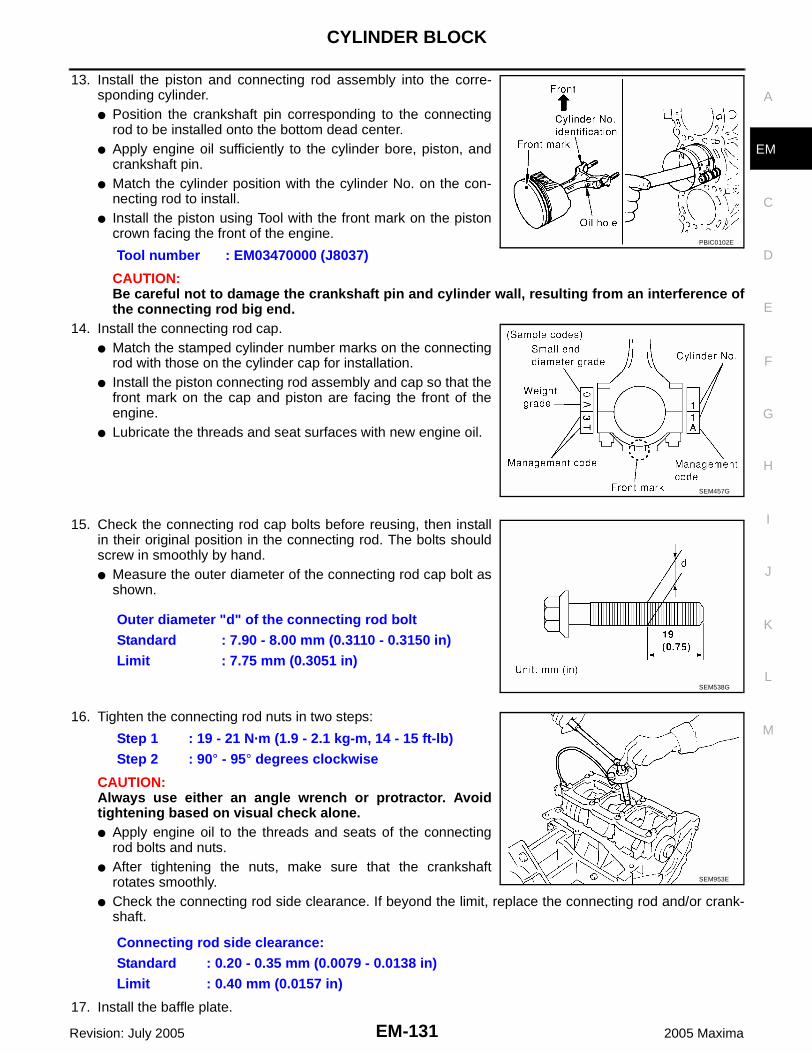
CYLINDER BLOCK
EM-131
C
D
E
F
G
H
I
J
K
L
M
A
EM
Revision: July 2005 2005 Maxima
13. Install the piston and connecting rod assembly into the corre-sponding cylinder. ● Position the crankshaft pin corresponding to the connecting
rod to be installed onto the bottom dead center. ● Apply engine oil sufficiently to the cylinder bore, piston, and
crankshaft pin. ● Match the cylinder position with the cylinder No. on the con-
necting rod to install. ● Install the piston using Tool with the front mark on the piston
crown facing the front of the engine.
CAUTION:Be careful not to damage the crankshaft pin and cylinder wall, resulting from an interference ofthe connecting rod big end.
14. Install the connecting rod cap. ● Match the stamped cylinder number marks on the connecting
rod with those on the cylinder cap for installation. ● Install the piston connecting rod assembly and cap so that the
front mark on the cap and piston are facing the front of theengine.
● Lubricate the threads and seat surfaces with new engine oil.
15. Check the connecting rod cap bolts before reusing, then installin their original position in the connecting rod. The bolts shouldscrew in smoothly by hand.● Measure the outer diameter of the connecting rod cap bolt as
shown.
16. Tighten the connecting rod nuts in two steps:
CAUTION:Always use either an angle wrench or protractor. Avoidtightening based on visual check alone.● Apply engine oil to the threads and seats of the connecting
rod bolts and nuts. ● After tightening the nuts, make sure that the crankshaft
rotates smoothly. ● Check the connecting rod side clearance. If beyond the limit, replace the connecting rod and/or crank-
shaft.
17. Install the baffle plate.
Tool number : EM03470000 (J8037)PBIC0102E
SEM457G
Outer diameter "d" of the connecting rod boltStandard : 7.90 - 8.00 mm (0.3110 - 0.3150 in)Limit : 7.75 mm (0.3051 in)
SEM538G
Step 1 : 19 - 21 N·m (1.9 - 2.1 kg-m, 14 - 15 ft-lb)Step 2 : 90° - 95° degrees clockwise
Connecting rod side clearance:Standard : 0.20 - 0.35 mm (0.0079 - 0.0138 in)Limit : 0.40 mm (0.0157 in)
SEM953E

EM-132Revision: July 2005
CYLINDER BLOCK
2005 Maxima
18. Install the knock sensor.
● Make sure that there is no foreign material on the cylinderblock mating surface and the back surface of the knock sen-sor.
● Install the knock sensor with the connector facing the rear ofthe engine.
● Do not tighten the knock sensor bolt while holding the con-nector.
● Make sure that the knock sensor does not interfere with otherparts.
CAUTION:If any impact by dropping occurs to the knock sensor, replace it with new one.
19. Install the pilot bushing (M/T) or pilot converter (A/T) using suit-able tool.
● Install pilot bushing or pilot converter as shown.
20. Install the flywheel (M/T), if equipped.● When installing flywheel to crankshaft, be sure to correctly
align crankshaft side dowel pin and flywheel side dowel pinhole.
● Secure the crankshaft using Tool.
Baffle plate bolts : 8.14 - 9.51 N·m (0.83 - 0.97 kg-m, 72 - 84 in-lb)
Knock sensor bolt : 20.6 - 26.5 N·m (2.1 - 2.7 kg-m, 16 - 19 in-lb)
PBIC0810E
Outer diameter of driftPilot bushing : Approx. 17 mm (0.67 in)Pilot converter : Approx. 33 mm (1.30 in)
PBIC0899E
SEM163B
Tool number : KV10117700 (J44716)
Flywheel bolts : 83 - 93 N·m (8.5 - 9.5 kg-m, 61 - 69 ft-lb)
SEM916G

CYLINDER BLOCK
EM-133
C
D
E
F
G
H
I
J
K
L
M
A
EM
Revision: July 2005 2005 Maxima
21. Install the drive plate (A/T), if equipped.● Install the drive plate and reinforce plate in the direction
shown.● Align dowel pins of crankshaft rear and drive plate with pin
holes of each part.● Secure the crankshaft using Tool.
● Tighten the drive plate bolts in one or two steps.
22. Unlock ring gear or flywheel, remove Tool.
23. Install the cylinder head. Refer to EM-102, "Removal and Installation" .24. Install the oil pump. Refer to LU-10, "INSTALLATION" .25. Install the timing chain. Refer to EM-70, "INSTALLATION" .26. Install the upper and lower oil pans. Refer to EM-34, "INSTALLATION" .27. Remove the engine from the stand and install the engine assembly into the vehicle. Refer to EM-117,
"Removal and Installation" .28. Assembly of the remaining parts is in the reverse order of disassembly.29. Fill the engine with the specified oil and coolant. Refer to MA-9, "Fluids and Lubricants" .
CAUTION:Wait at least 30 minutes for the sealant to set-up before filling the engine with fluids and running it.
How to Select Piston and Bearing EBS00JB9
DESCRIPTION
* For the service parts, the grade for fitting cannot be selected between a piston pin and a connecting rod.(Only 0 grade is available.) The information at the shipment from the plant is described as a reference.● The identification grade stamped on each part is the grade for the dimension measured in new condition.
This grade cannot apply to reused parts.● For reused or repair parts, measure the dimension accurately. Determine the grade by comparing the
measurement with the values or each selection table.● For details of the measurement method of each part, the reuse standards and the selection method of the
selective fitting parts, refer to the text.
Tool number : KV10117700 (J44716)
Drive plate bolts : 83 - 93 N·m (8.5 - 9.5 kg-m, 61 - 69 ft-lb)
PBIC0910E
Tool number : KV10117700 (J44716)
Selection points Selection parts Selection items Selection methods
Between cylinder block and crankshaft
Main bearingMain bearing grade (bearing thickness)
Determined by matching of cyl-inder block bearing housing grade (inner diameter of hous-ing) and crankshaft journal grade (outer diameter of jour-nal)
Between crankshaft and con-necting rod
Connecting rod bearingConnecting rod bearing grade (bearing thickness)
Combining service grades for connecting rod big end inner diameter and crankshaft pin outer diameter determine con-necting rod bearing selection.
Between cylinder block and pis-ton
Piston and piston pin assembly (The piston is available together with piston pin as an assembly.)
Piston grade (piston outer diameter)
Piston grade = cylinder bore grade (inner diameter of bore)
*Between piston and connect-ing rod
– – –

EM-134Revision: July 2005
CYLINDER BLOCK
2005 Maxima
HOW TO SELECT A PISTONWhen New Cylinder Block is Used● Check the cylinder bore grade (1, 2 or 3) on rear side of cylinder
block, and select a piston of the same grade.● The piston is available with piston pin as a set for the service
part. (Only 0 grade piston pin is available.)
When Cylinder Block is Reused1. Measure the cylinder block bore inner diameter.2. Determine the bore grade by comparing the measurement with
the values under the cylinder bore inner diameter of the EM-134,"Piston Selection Table" .
3. Select the piston of the same grade.
Piston Selection TableUnit: mm (in)
NOTE:● The piston is available together with piston pin as an assembly.● The piston pin (piston pin bore) grade is provided only for the parts installed at the plant. For service parts,
no piston pin grades can be selected. (Only 0 grade is available.)● No grade mark is indicated on 2 grade piston.
SEM756G
PBIC0812E
Grade 1 2 (or no mark) 3 oversize (service)
Inner diameter of cylin-der bore
95.500 - 95.510 (3.7598 - 3.7602)
95.510 - 95.520 (3.7602 - 3.7606
95.520 - 95.530 (3.7606 - 3.7610)
95.700 - 95.730 (3.7677 - 3.7689)
Outer diameter of piston95.480 - 95.490 (3.7590
- 3.7594)95.490 - 95.500 (3.7594
- 3.7598)95.500 - 95.510 (3.7598
- 3.7602)95.680 - 95.710 (3.7669 - 3.7681)
SEM882E
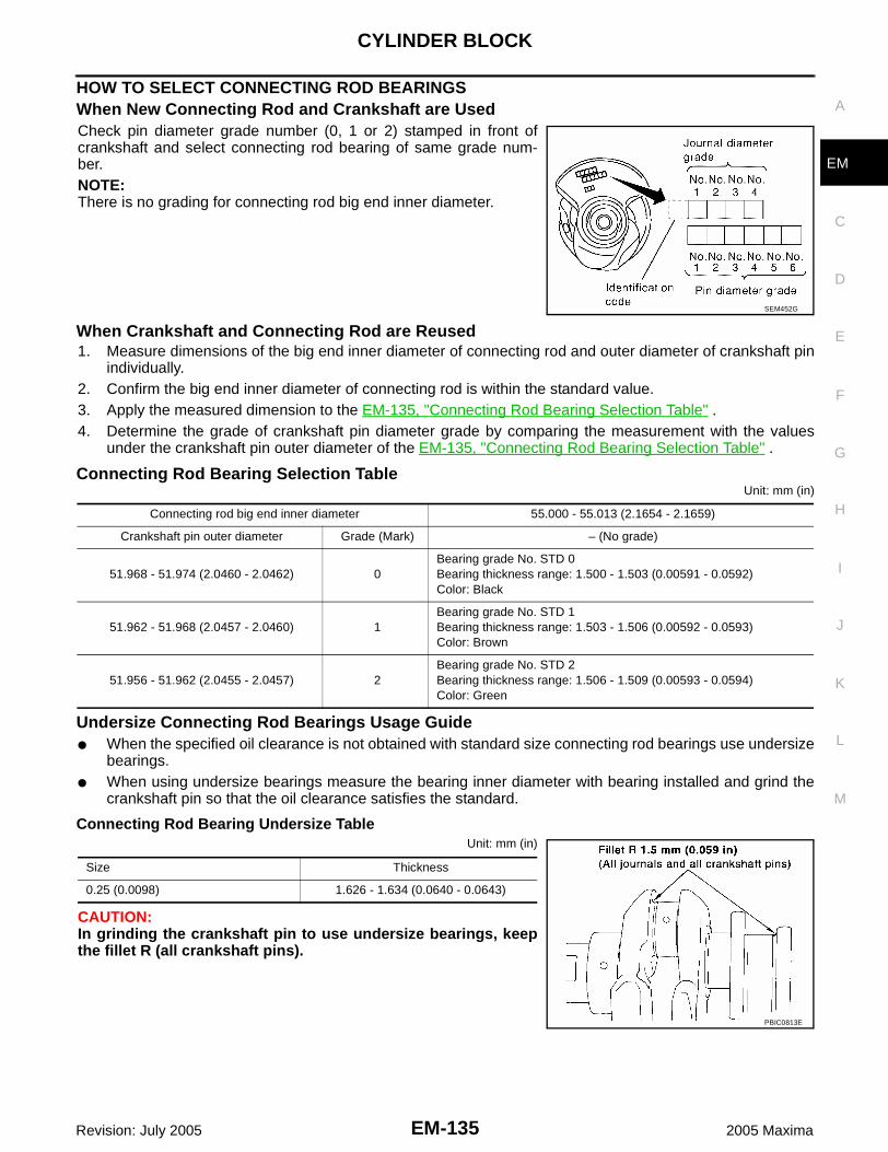
CYLINDER BLOCK
EM-135
C
D
E
F
G
H
I
J
K
L
M
A
EM
Revision: July 2005 2005 Maxima
HOW TO SELECT CONNECTING ROD BEARINGSWhen New Connecting Rod and Crankshaft are UsedCheck pin diameter grade number (0, 1 or 2) stamped in front ofcrankshaft and select connecting rod bearing of same grade num-ber.NOTE:There is no grading for connecting rod big end inner diameter.
When Crankshaft and Connecting Rod are Reused1. Measure dimensions of the big end inner diameter of connecting rod and outer diameter of crankshaft pin
individually.2. Confirm the big end inner diameter of connecting rod is within the standard value.3. Apply the measured dimension to the EM-135, "Connecting Rod Bearing Selection Table" .4. Determine the grade of crankshaft pin diameter grade by comparing the measurement with the values
under the crankshaft pin outer diameter of the EM-135, "Connecting Rod Bearing Selection Table" .
Connecting Rod Bearing Selection TableUnit: mm (in)
Undersize Connecting Rod Bearings Usage Guide● When the specified oil clearance is not obtained with standard size connecting rod bearings use undersize
bearings.● When using undersize bearings measure the bearing inner diameter with bearing installed and grind the
crankshaft pin so that the oil clearance satisfies the standard.
Connecting Rod Bearing Undersize TableUnit: mm (in)
CAUTION:In grinding the crankshaft pin to use undersize bearings, keepthe fillet R (all crankshaft pins).
SEM452G
Connecting rod big end inner diameter 55.000 - 55.013 (2.1654 - 2.1659)
Crankshaft pin outer diameter Grade (Mark) – (No grade)
51.968 - 51.974 (2.0460 - 2.0462) 0Bearing grade No. STD 0Bearing thickness range: 1.500 - 1.503 (0.00591 - 0.0592)Color: Black
51.962 - 51.968 (2.0457 - 2.0460) 1Bearing grade No. STD 1Bearing thickness range: 1.503 - 1.506 (0.00592 - 0.0593)Color: Brown
51.956 - 51.962 (2.0455 - 2.0457) 2Bearing grade No. STD 2Bearing thickness range: 1.506 - 1.509 (0.00593 - 0.0594)Color: Green
Size Thickness
0.25 (0.0098) 1.626 - 1.634 (0.0640 - 0.0643)
PBIC0813E

EM-136Revision: July 2005
CYLINDER BLOCK
2005 Maxima
HOW TO SELECT MAIN BEARINGSWhen New Cylinder Block and Crankshaft are Used1. EM-137, "Main Bearing Selection Table" rows correspond to
bearing housing grade on rear left side of cylinder block.
2. Apply journal diameter grade stamped on crankshaft front sideto column in EM-137, "Main Bearing Selection Table" .
3. Find sign (main bearing grade) at crossing of row and column inEM-137, "Main Bearing Selection Table" .
When Cylinder Block and Crankshaft are Reused1. Measure inner diameter of cylinder block main bearing housing and outer diameter of crankshaft journal.2. Find measured dimension in "Cylinder block bearing housing inner diameter" row of EM-137, "Main Bear-
ing Selection Table" .3. Find the measured dimension in "Crankshaft main journal diameter" column in EM-137, "Main Bearing
Selection Table" .4. Select main bearing grade at the point where selected row and column intersect.
SEM756G
SEM452G

CYLINDER BLOCK
EM-137
C
D
E
F
G
H
I
J
K
L
M
A
EM
Revision: July 2005 2005 Maxima
Main Bearing Selection Table
PBIC0814E

EM-138Revision: July 2005
CYLINDER BLOCK
2005 Maxima
Main Bearing Grade Table (All Journals)
Undersize Main Bearing Usage Guide● Use undersize bearing when oil clearance with standard size main bearing is not within specification.
CAUTION:Keep fillet R when grinding crankshaft journal in order touse undersize bearing (all journals).
● When using undersize bearing, measure the bearing inner diam-eter with bearing installed, and grind journal until oil clearancefalls within specification.
Main Bearing Undersize TableUnit: mm (in)
Grade number Thickness “T” mm (in) Width “W” mm (in)Identification color
(UPR/LWR)Remarks
0 2.000 - 2.003 (0.0787 - 0.0789)
19.9 - 20.1(0.783 - 0.791)
Black
Grade is the same for upper and lower bear-ings.
1 2.003 - 2.006 (0.0789 - 0.0790) Brown
2 2.006 - 2.009 (0.0790 - 0.0791) Green
3 2.009 - 2.012 (0.0791 - 0.0792) Yellow
4 2.012 - 2.015 (0.0792 - 0.0793) Blue
5 2.015 - 2.018 (0.0793 - 0.0794) Pink
6 2.018 - 2.021 (0.0794 - 0.0796) Purple
7 2.021 - 2.024 (0.0796 - 0.0797) White
01UPR 2.003 - 2.006 (0.0789 - 0.0790)
Brown/Black
Grade is different for upper and lower bear-ings.
LWR 2.000 - 2.003 (0.0787 - 0.0789)
12UPR 2.006 - 2.009 (0.0790 - 0.0791)
Green/BrownLWR 2.003 - 2.006 (0.0789 - 0.0790)
23UPR 2.009 - 2.012 (0.0791 - 0.0792)
Yellow/GreenLWR 2.006 - 2.009 (0.0790 - 0.0791)
34UPR 2.012 - 2.015 (0.0792 - 0.0793)
Blue/YellowLWR 2.009 - 2.012 (0.0791 - 0.0792)
45UPR 2.015 - 2.018 (0.0793 - 0.0794)
Pink/BlueLWR 2.012 - 2.015 (0.0792 - 0.0793)
56UPR 2.018 - 2.021 (0.0794 - 0.0796)
Purple/PinkLWR 2.015 - 2.018 (0.0793 - 0.0794)
67UPR 2.021 - 2.024 (0.0796 - 0.0797)
White/PurpleLWR 2.018 - 2.021 (0.0794 - 0.0796)
PBIC0813E
Size Thickness
0.25 (0.0098) 2.132 - 2.140 (0.0839 - 0.0843)

CYLINDER BLOCK
EM-139
C
D
E
F
G
H
I
J
K
L
M
A
EM
Revision: July 2005 2005 Maxima
Inspection After Disassembly EBS00JBA
CRANKSHAFT END PLAY● Using a dial indicator, measure the clearance between the thrust
bearings and the connecting rods when the crankshaft is movedfrom front to rear.
● If beyond the limit, replace the thrust bearings and measureagain. If still beyond the limit, replace the crankshaft.
1.
CONNECTING ROD SIDE CLEARANCE● Measure the side clearance between the connecting rod and
crankshaft with a feeler gauge.
● If beyond the limit, replace the connecting rod and measureagain. If still beyond the limit, replace the crankshaft.
1.
PISTON AND PISTON PIN CLEARANCEInner Diameter of Piston Pin Hole● Measure the inner diameter of piston pin hole "dp".
Outer Diameter of Piston Pin● Measure outer diameter of piston pin "Dp".
Standard : 0.10 - 0.25 mm (0.0039 - 0.0098 in)Limit : 0.30 mm (0.0118 in)
SEM852E
Standard : 0.20 - 0.35 mm (0.0079 - 0.0138 in)Limit : 0.40 mm (0.0157 in)
PBIC0815E
Standard diameter "dp"Grade No. 0 : 21.993 - 21.999 mm (0.8659 - 0.8661 in)Grade No. 1 : 21.999 - 22.005 mm (0.8661 - 0.8663 in)
AEM023
Standard diameter "Dp"Grade No. 0 : 21.989 - 21.995 mm (0.8657 - 0.8659 in)Grade No. 1 : 21.995 - 22.001 mm (0.8659 - 0.8662 in)
AEM024

EM-140Revision: July 2005
CYLINDER BLOCK
2005 Maxima
Piston and Piston Pin Interference FitStandard Interference Fit = "Dp" – "dp"
● If clearance is exceeds specification, replace either or both ofpiston/piston pin assembly and connecting rod assembly withreference to specification of each part.
● When replacing piston/piston pin assembly, refer to EM-143,"PISTON-TO-CYLINDER BORE CLEARANCE" .
PISTON RING SIDE CLEARANCE● Measure side clearance of piston ring and piston ring groove
with feeler gauge.
● If out of specification, replace piston ring assembly. If clearance exceeds maximum limit with new rings,replace piston
PISTON RING END GAP● Check if inner diameter of cylinder bore is within specification. Refer to EM-143, "PISTON-TO-CYLINDER
BORE CLEARANCE" .● Insert piston ring until it is in the middle of the cylinder bore and
measure the end gap.
● If out of specification, replace piston ring. If gap still exceeds the limit even with a new ring, re-bore cylin-der and use oversized piston and piston ring.
Standard : 0.002 mm - 0.006 mm (0.0001 - 0.0002 in)
SEM838F
Standard Side ClearanceTop ring : 0.045 - 0.080 mm (0.0018 - 0.0031 in)2nd ring : 0.030 - 0.070 mm (0.0012 - 0.0028 in)Oil ring : 0.065 - 0.135 mm (0.0026 - 0.0053 in)
Maximum LimitTop ring : 0.11 mm (0.0043 in)2nd ring : 0.1 mm (0.004 in)Oil ring : —
SEM024AA
StandardTop ring : 0.23 - 0.33 mm (0.0091 - 0.0130 in)2nd ring : 0.33 - 0.48 mm (0.0130 - 0.0189 in)Oil ring : 0.20 - 0.50 mm (0.0079 - 0.0197 in)
Limit:Top ring : 0.54 mm (0.0213 in)2nd ring : 0.80 mm (0.0315 in)Oil ring : 0.95 mm (0.0374 in)
SEM599A

CYLINDER BLOCK
EM-141
C
D
E
F
G
H
I
J
K
L
M
A
EM
Revision: July 2005 2005 Maxima
CONNECTING ROD BEND AND TORSION
● If it exceeds the limit, replace connecting rod assembly.
CONNECTING ROD BEARING HOUSING DIAMETER (BIG END)● Install the connecting rod cap without the connecting rod bearing
installed. After tightening the connecting rod nut to the specifiedtorque, measure the connecting rod bearing housing big endinner diameter using an inside micrometer.
CONNECTING ROD BUSHING OIL CLEARANCE (SMALL END)Inner Diameter of Connecting Rod (Small End)● Measure inner diameter of piston pin bushing.
Bend : Limit 0.15 mm (0.0059 in) per 100 mm (3.94 in) length
Torsion : Limit 0.30 mm (0.0118 in) per 100 mm (3.94 in) length
SEM038F
SEM003F
Standard : 55.000 - 55.013 mm (2.1654 - 2.1659 in)
PBIC1641E
StandardGrade No. 0 : 22.000 - 22.006 mm (0.8661 - 0.8664 in)Grade No. 1 : 22.006 - 22.012 mm (0.8664 - 0.8666 in)
PBIC0120E

EM-142Revision: July 2005
CYLINDER BLOCK
2005 Maxima
Outer Diameter of Piston Pin● Measure outer diameter of piston pin.
Connecting Rod Bushing Oil Clearance (Small End)(Connecting rod small end oil clearance) = (Inner diameter of con-necting rod small end) – (Outer diameter of piston pin)
● If the measured value exceeds the standard, replace the con-necting rod assembly and/or piston and piston pin assembly.
● If replacing the piston and piston pin assembly, refer to the Tablefor Selective Fitting for Piston to select the piston correspondingto the applicable bore grade of the cylinder block to be used.Refer to EM-143, "PISTON-TO-CYLINDER BORE CLEAR-ANCE" .
● If replacing the connecting rod assembly, refer to EM-141, "CONNECTING ROD BUSHING OIL CLEAR-ANCE (SMALL END)" .
Factory installed parts grading:● Service parts apply only to grade 0.
Unit: mm (in)
*: After installing in connecting rod
CYLINDER BLOCK DISTORTION● Using a scraper, remove any old gasket material on the cylinder
block surface, and remove any oil, scale, carbon, or other con-tamination. CAUTION:Be careful not to allow gasket flakes to enter the oil or cool-ant passages.
● Measure the distortion on the block upper face at different pointsin six directions.
● If out of specification, resurface the cylinder block. The allow-able amount of resurfacing is dependent on the amount of anycylinder head resurfacing. The resurfacing limit is [amount of cylinder head resurfacing] + [amount of cyl-inder head resurfacing] = 0.2 mm (0.008 in).
StandardGrade No. 0 : 21.989 - 21.995 mm (0.8657 - 0.8659 in)Grade No. 1 : 21.995 - 22.001 mm (0.8659 -0.8662 in)
PBIC0117E
Standard : 0.005 - 0.017 mm (0.0002 - 0.0007 in)Limit : 0.030 mm (0.0012 in)
SEM457G
Grade 0 1
Piston pin bushing inner diameter*
22.000 - 22.006 (0.8661 - 0.8664)
22.006 - 22.012 (0.8664 - 0.8666)
Piston pin outer diameter 21.989 - 21.995 (0.8657 - 0.8659)
21.995 - 22. 001 (0.8659 - 0.8662)
Piston pin hole diameter 21.993 - 21.999 (0.8659 - 0.8661)
21.999 - 22.005 (0.8661 - 0.8663) SEM838F
Distortion limit : 0.10 mm (0.0039 in)SEM123C

CYLINDER BLOCK
EM-143
C
D
E
F
G
H
I
J
K
L
M
A
EM
Revision: July 2005 2005 Maxima
INNER DIAMETER OF MAIN BEARING HOUSING● Install the main bearing caps with the main bearings removed,
and tighten the mounting bolts to the specified torque.● Using a bore gauge, measure the inner diameter of the main
bearing housing.
● If out of the standard, replace the cylinder block and main bear-ing caps as an assembly. NOTE:These components cannot be replaced individually, since theywere processed together.
PISTON-TO-CYLINDER BORE CLEARANCE1. Using a bore gauge, measure cylinder bore for wear, out-of-round and taper. The X axis is in the longitudi-
nal direction of the engine.
Cylinder bore inner diameter
If it exceeds the limit, rebore all cylinders. Replace cylinder blockif necessary.
2. Check for scratches and seizure. If seizure is found, hone it.● If both cylinder block and piston are replaced with new ones,
select piston of the same grade number punched on cylinderblock rear position. These numbers are punched in either Ara-bic or Roman numerals.
Cylinder block height : 214.95 - 215.05 mm (8.4626 - 8.4665 in)
Standard : 63.993 - 64.017 mm (2.5194 - 2.5203 in)
PBIC1643E
Grade No. Standard inner diameter Wear limit
No. 1 95.500 - 95.510 mm (3.7598 - 3.7602 in)
0.20 mm (0.0079 in)No. 2 95.510 - 95.520 mm (3.7602 - 3.7606 in)
No. 3 95.520 - 95.530 mm (3.7606 - 3.7610 in)
SEM843E
Out-of-round (Differ-ence between, X - Y)
: less than 0.015 mm (0.0006 in)
Taper (Difference between, C - A)
: less than 0.015 mm (0.0006 in)
SEM321AA
SEM756G

EM-144Revision: July 2005
CYLINDER BLOCK
2005 Maxima
3. Measure piston skirt diameter.
4. Check that piston-to-bore clearance is within specification.
● The piston-to-bore clearance is measured at the "B" level inthe cylinder as shown.
5. Determine piston oversize according to amount of cylinder wear.● Oversize pistons are available for service.● If oversize piston is used, use it for all cylinders with oversize piston ring. Refer to EM-157, "PISTON,
PISTON RING AND PISTON PIN" .6. Cylinder bore size is determined by adding piston-to-bore clearance to piston diameter “A”.
7. Install main bearing caps, and tighten to the specified torque. Otherwise, cylinder bores may be distortedafter boring.
8. Cut cylinder bores.● When any cylinder needs boring, all other cylinders must also be bored.● Do not cut too much out of cylinder bore at a time. Cut only 0.05 mm (0.0020 in) or so in diameter at a
time.9. Hone cylinders to obtain specified piston-to-bore clearance.10. Measure finished cylinder bore for out-of-round and taper.
● Measurement should be done after cylinder bore cools down.
Piston diameter “A” : Refer to EM-157, "PIS-TON, PISTON RING AND PISTON PIN" .
Measuring point “a” (distance from the top)
: 41.0 mm (1.614 in)
SEM258C
Piston-to-bore clearance at “B”
: 0.010 - 0.030 mm (0.0004 - 0.0012 in)
SEM321AA
Rebored size calculation : D = A + B − Cwhere, D : Bored diameter A : Piston diameter as measured B : Piston-to-bore clearance C : Honing allowance 0.02 mm (0.0008 in)

CYLINDER BLOCK
EM-145
C
D
E
F
G
H
I
J
K
L
M
A
EM
Revision: July 2005 2005 Maxima
OUTER DIAMETER OF CRANKSHAFT JOURNALMeasure outer diameter of crankshaft journals. Refer to EM-145,"OUT-OF-ROUND AND TAPER OF CRANKSHAFT" .
OUTER DIAMETER OF CRANKSHAFT PINMeasure outer diameter of crankshaft pin. Refer to EM-145, "OUT-OF-ROUND AND TAPER OF CRANK-SHAFT" .
OUT-OF-ROUND AND TAPER OF CRANKSHAFT● Check the crankshaft main and pin journals for scoring, wear, or
cracks.● Measure the journals for taper and out-of-round.
CRANKSHAFT RUNOUT● Place a V-block on a precise flat table to support the journals on the both ends of the crankshaft.● Place a dial gauge straight up on the No. 3 journal. ● While rotating the crankshaft, read the movement of the pointer
on the dial gauge.
OIL CLEARANCE OF CONNECTING ROD BEARINGMethod by Calculation1. Install the connecting rod bearing to the connecting rod and cap.2. Install the connecting rod cap to the connecting rod. Tighten to specification. Refer to EM-126, "ASSEM-
BLY" .
PBIC0127E
StandardOut-of-round (differ-ence between, X - Y)
: 0.002 mm (0.0001 in)
Taper (difference between, A - B)
: 0.002 mm (0.0001 in)
SEM316A
Runout limit (total indicator reading)
: less than 0.10 mm (0.0039 in)
SEM346D

EM-146Revision: July 2005
CYLINDER BLOCK
2005 Maxima
3. Measure the inner diameter "C" of each connecting rod (big end)as shown.
4. Measure the outer diameter "Dp" of each crankshaft pin journal.5. Calculate the connecting rod bearing clearance.
Connecting rod bearing clearance = C - Dp
6. If the clearance cannot be adjusted within the standard of anybearing, grind the crankshaft journal and use undersized bear-ings. Refer to EM-135, "HOW TO SELECT CONNECTING RODBEARINGS" .
Method of Using Plastigage● Remove oil and dust on the crankshaft pin and the surfaces of
each bearing completely. ● Cut a Plastigage slightly shorter than the bearing width, and
place it in crankshaft axial direction, avoiding oil holes.● Install the connecting rod bearings to the connecting rod cap,
and tighten the connecting rod nuts to the specified torque. CAUTION:Never rotate the crankshaft.
● Remove the connecting rod cap and bearings, and using thescale on the Plastigage bag, measure the Plastigage width. NOTE:The procedure when the measured value exceeds the repair limit is same as that described in EM-145,"Method by Calculation" .
OIL CLEARANCE OF MAIN BEARINGMethod by Calculation1. Install the main bearings to the cylinder block and bearing cap. Refer to EM-126, "ASSEMBLY" .2. Calculate the main bearing clearance. (Oil clearance) = (Inner diameter of main bearing) - (Outer diameter
of crankshaft journal)
3. If the calculated clearance exceeds the specified limit, replacethe bearings. Refer to EM-136, "HOW TO SELECT MAINBEARINGS" .
WBIA0335E
Standard : 0.034 - 0.059 mm (0.0013 - 0.0023 in)Limit : 0.070 mm (0.0028 in)
AEM034
SEM142
Standard : 0.035 - 0.045 mm (0.0014 - 0.0018 in)Limit : 0.065 mm (0.0026 in)
PBIC1644E

CYLINDER BLOCK
EM-147
C
D
E
F
G
H
I
J
K
L
M
A
EM
Revision: July 2005 2005 Maxima
Method of Using Plastigage● Remove oil and dust on the crankshaft pin and the surfaces of
each bearing completely. ● Cut a Plastigage slightly shorter than the bearing width, and
place it in crankshaft axial direction, avoiding oil holes.● Install the main bearings and main bearing caps. Refer to EM-
126, "ASSEMBLY" . CAUTION:Never rotate the crankshaft.
● Remove the main bearing caps and bearings, and using thescale on the Plastigage bag, measure the Plastigage width. NOTE:The procedure when the measured value exceeds the repair limit is same as that described in EM-146,"Method by Calculation" .
CRUSH HEIGHT OF MAIN BEARING● When the bearing cap is removed after being tightened to the
specified torque with main bearings installed, the tip end of thebearing must protrude. Refer to EM-126, "ASSEMBLY" for tight-ening procedure.
● If the standard is not met, replace main bearings.
CRUSH HEIGHT OF CONNECTING ROD BEARING● When the connecting rod bearing cap is removed after being
tightened to the specified torque with main bearings installed,the tip end of the bearing must protrude. Refer to EM-126,"ASSEMBLY" for tightening procedure.
● If the standard is not met, replace connecting rod bearings.
OUTER DIAMETER OF MAIN BEARING CAP BOLTS● Measure outer diameters (d1, d2) at two positions as shown.● Measure d2 at a point with A.
● When the value of d1 - d2 exceeds the limit (a large difference indimensions) replace the bolt with a new one.
SEM142
Standard : There must be a crush height.
SEM502G
Standard : There must be a crush height.
PBIC1646E
Limit : 0.11 mm (0.0051 in)
PBIC0911E

EM-148Revision: July 2005
CYLINDER BLOCK
2005 Maxima
OUTER DIAMETER OF CONNECTING ROD BOLTS● Measure outer diameter d as shown.
● When the value of d exceeds the limit (when it becomes thinner)replace the bolt with a new one.
DRIVE PLATE RUNOUT (A/T)Runout (Total Indicator Reading):
CAUTION:● The signal plate is built into the drive assembly. Be careful
not to damage the signal plate, particularly the teeth.● Check the drive plate and signal plate for deformation or
cracks.● Keep any magnetized objects away from the signal plate,
particularly the teeth.
FLYWHEEL RUNOUT (M/T)NOTE:● This inspection is for double mass flywheel only.● Do not disassemble the double mass flywheel.
Flywheel Deflection● Measure the deflection of the flywheel contact surface to the
clutch with a dial gauge.● Measure the deflection at 210 mm (8.27 in) diameter.
● When measured value exceeds the limit, replace the flywheelwith a new one.
Movement Around in Rotation DirectionCheck the movement amount with the following procedure:
Standard : 7.90 - 8.00 mm (0.3110 - 0.3150 in)
Limit : 7.75 mm (0.3051 in)
PBIC0912E
Drive plate (A/T) : less than 0.15 mm (0.0059 in)
SEM849EB
SEM760G
Standard : 0.45 mm (0.0177 in) or lessLimit : 1.3 mm (0.051 in) or less
SBIA0287E

CYLINDER BLOCK
EM-149
C
D
E
F
G
H
I
J
K
L
M
A
EM
Revision: July 2005 2005 Maxima
1. Install a bolt to clutch cover mounting hole and place a torque wrench on the extended line of the flywheelcenter line. ● Tighten the bolt at a force of 9.8 N·m (1 kg-m, 87 in-lb) to keep it from loosening.
2. Put a mating mark on the circumference of the two flywheel masses without applying any load (measure-ment standard points).
3. Apply a force of 9.8 N·m (1 kg-m, 87 in-lb) in each direction, and mark the movement amount on the masson the transaxle side.
4. Measure dimensions of movement amounts A and B on the cir-cumference of the flywheel on the transaxle side.
● When the measured value exceeds the standard, replace theflywheel.
OIL JET● Check nozzle for deformation and damage.● Blow compressed air from nozzle, and check for clogs.● If it is not satisfied, replace oil jet.
OIL JET RELIEF VALVE● Using a clean plastic stick, press check valve in oil jet relief
valve. Make sure that valve moves smoothly with proper reac-tion force.
● If it is not satisfied, replace oil jet relief valve.
Flywheel movement in rotation direction
: 24 mm (0.94 in) or less
WBIA0224E
EMU0468D

EM-150Revision: July 2005
SERVICE DATA AND SPECIFICATIONS (SDS)
2005 Maxima
SERVICE DATA AND SPECIFICATIONS (SDS) PFP:00100
Standard and Limit EBS00JBB
GENERAL SPECIFICATIONSCylinder arrangement V-6
Displacement cm3 (cu in) 3,498 (213.45)
Bore and stroke mm (in) 95.5 x 81.4 (3.760 x 3.205)
Valve arrangement DOHC
Firing order 1-2-3-4-5-6
Number of piston ringsCompression 2
Oil 1
Number of main bearings 4
Compression ratio 10.0:1
Compression pressure
kPa (kg/cm2 , psi)/300 rpm
Standard 1,275 (13.0, 185)
Minimum 981 (10.0, 142)
Differential limit between cylinders
98 (1.0, 14)
Cylinder number
Valve timing (IVTC - OFF)
Unit: degree
a b c d e f
240 238 - 6 64 8 52
SEM713A
PBIC0187E

SERVICE DATA AND SPECIFICATIONS (SDS)
EM-151
C
D
E
F
G
H
I
J
K
L
M
A
EM
Revision: July 2005 2005 Maxima
DRIVE BELT
*: If belt tension gauge cannot be installed at check points shown, check drive belt tension at different location on the belt.
INTAKE MANIFOLD COLLECTOR, INTAKE MANIFOLD AND EXHAUST MANIFOLDUnit: mm (in)
SPARK PLUG
Deflection adjustment Unit: mm (in) Tension adjustment* Unit: N (kg, lb)
Used beltNew belt
Used beltNew belt
Limit After adjustment Limit After adjustment
Alternator and air conditioning compressor
7 (0.28) 4.2 - 4.6 (0.17 - 0.18)
3.7 - 4.1 (0.15 - 0.16)
294 (30, 66)730 - 818
(74.5 - 83.5,164 - 184)
838 - 926(85.5 - 94.5,188 - 208)
Power steering pump
11 (0.43) 7.3 - 8.0 (0.29 - 0.30)
6.5 - 7.2 (0.26 - 0.28)
196 (20, 44)495 - 583
(50.5 - 59.5,111 - 131)
603 - 691(61.5 - 70.5,
135.6 - 155.4)
Applied pushing force
98 N (10 kg, 22 lb) —
LLIA0060E
Item Limit
Surface distortion
Intake manifold collector 0.1 (0.004)
Intake manifold 0.1 (0.004)
Exhaust manifold 0.3 (0.012)
Make NGK
Standard type PLFR5A-11
Hot type PLFR4A-11
Cold type PLFR6A-11
Gap (nominal) 1.1 mm (0.043 in)

EM-152Revision: July 2005
SERVICE DATA AND SPECIFICATIONS (SDS)
2005 Maxima
CYLINDER HEADUnit: mm (in)
VALVEValve Dimensions
Unit: mm (in)
Valve ClearanceUnit: mm (in)
*: Approximately 80°C (176°F)
Standard Limit
Head surface distortion — 0.1 (0.004)
Nominal cylinder head height "H" 126.3 - 126.5 (4.972 - 4.980) —
PBIC0924E
Valve head diameter “D”Intake 37.0 - 37.3 (1.4567 - 1.4685)
Exhaust 31.2 - 31.5 (1.228 - 1.240)
Valve length “L”Intake 96.21 - 96.71 (3.7878 - 3.8075)
Exhaust 93.74 - 94.24 (3.6905 - 3.7102)
Valve stem diameter “d”Intake 5.965 - 5.980 (0.2348 - 0.2354)
Exhaust 5.945 - 5.960 (0.2341 - 0.2346)
Valve seat angle “α”Intake
45°25′ - 45°75′Exhaust
Valve margin “T”Intake 1.15 - 1.45 (0.0453 - 0.0571)
Exhaust 1.45 - 1.75 (0.0571 - 0.0689)
Valve margin “T” limit More than 0.5 (0.020)
Valve stem end surface grinding limit Less than 0.2 (0.008)
Valve oil seal installation height 14.3 14.9 mm (0.563 - 0.587 in)
SEM188
Cold Hot* (reference data)
Intake 0.26 - 0.34 (0.010 - 0.013) 0.304 - 0.416 (0.012 - 0.016)
Exhaust 0.29 - 0.37 (0.011 - 0.015) 0.308 - 0.432 (0.012 - 0.017)

SERVICE DATA AND SPECIFICATIONS (SDS)
EM-153
C
D
E
F
G
H
I
J
K
L
M
A
EM
Revision: July 2005 2005 Maxima
Valve Spring
Valve LifterUnit: mm (in)
Available Valve Lifter
Free height mm (in) 46.90 (1.8465)
Pressure N (kg, lb) at height mm (in)Standard 166 - 188 (16.9 - 19.2, 37.3 - 42.3) at 37.0 (1.457)
Limit 378 - 426 (38.6 - 43.5, 85.0 - 95.8) at 27.8 (1.094)
Out-of-square mm (in) Less than 2.0 (0.079)
Valve lifter outer diameter 33.977 - 33.987 (1.3377 - 1.3381)
Lifter lifter bore diameter 34.000 - 34.016 (1.3386 - 1.3392)
Clearance between lifter and lifter guide 0.013 - 0.039 (0.0005 - 0.0015)
Identification Mark Thickness mm (in)
788U or R 7.88 (0.3102)
790U or R 7.90 (0.3110)
792U or R 7.92 (0.3118)
794U or R 7.94 (0.3126)
796U or R 7.96 (0.3134)
798U or R 7.98 (0.3142)
800U or R 8.00 (0.3150)
802U or R 8.02 (03.157)
804U or R 8.04 (0.3165)
806U or R 8.06 (0.3173)
808U or R 8.08 (0.3181)
810U or R 8.10 (0.3189)
812U or R 8.12 (0.3197)
814U or R 8.14 (0.3205)
816U or R 8.16 (0.3213)
818U or R 8.18 (0.3220)
820U or R 8.20 (0.3228)
822U or R 8.22 (0.3236)
824U or R 8.24 (0.3244)
826U or R 8.26 (0.3252)
828U or R 8.28 (0.3260)
830U or R 8.30 (0.3268)
832U or R 8.32 (0.3276)
834U or R 8.34 (0.3283)
SEM758G

EM-154Revision: July 2005
SERVICE DATA AND SPECIFICATIONS (SDS)
2005 Maxima
Valve GuideUnit: mm (in)
836U or R 8.36 (0.3291)
838U or R 8.38 (0.3299)
840U or R 8.40 (0.3307)
Identification Mark Thickness mm (in)
SEM758G
Standard Service
Valve guide Outer diameter 10.023 - 10.034 (0.3946 - 0.3950) 10.223 - 10.234 (0.4025 - 0.4029)
Valve guide Inner diameter (Finished size) 6.000 - 6.018 (0.2362 - 0.2369)
Valve guide hole diameter 9.975 - 9.996 (0.3927 - 0.3935) 10.175 - 10.196 (0.4006 - 0.4014)
Interference fit of valve guide 0.027 - 0.059 (0.0011 - 0.0023)
Standard Limit
Valve to valve guide clear-ance
Intake 0.020 - 0.053 (0.0008 - 0.0021) 0.08 (0.0031)
Exhaust 0.030 - 0.063 (0.0012 - 0.0025) 0.09 (0.004)
Valve deflectionIntake — 0.24 (0.0094)
Exhaust — 0.28 (0.0110)
Projection length “L” 12.6 - 12.8 (0.496 - 0.504)
SEM950E

SERVICE DATA AND SPECIFICATIONS (SDS)
EM-155
C
D
E
F
G
H
I
J
K
L
M
A
EM
Revision: July 2005 2005 Maxima
Valve SeatUnit: mm (in)
Standard Service
Cylinder head seat recess diameter (D)
Intake 38.000 - 38.016 (1.4961 - 1.4967) 38.500 - 38.516 (1.5157 - 1.5164)
Exhaust 32.200 - 32.216 (1.2677 - 1.2683) 32.700 - 32.716 (1.2874 - 1.2880)
Valve seat interference fitIntake 0.081 - 0.113 (0.0032 - 0.0044)
Exhaust 0.064 - 0.096 (0.0025 - 0.0038)
Valve seat outer diameter (d)Intake 38.097 - 38.113 (1.4999 - 1.5005) 38.597 - 38.613 (1.5196 - 1.5202)
Exhaust 32.280 - 32.296 (1.2709 - 1.2715) 32.780 - 32.796 (1.2905 - 1.2912)
Height (h)Intake 5.9 - 6.0 (0.232 - 0.236) 5.05 - 5.15 (0.1988 - 0.2028)
Exhaust 5.9 - 6.0 (0.232 - 0.236) 4.95 - 5.05 (0.1949 - 0.1988)
Depth (H) 5.9 - 6.1 (0.232 - 0.240)
Valve seat resurface limit (L)Intake 41.07 - 41.67 (1.6169 - 1.6405)
Exhaust 41.00 - 41.60 (1.6142 - 1.6378)
SEM021EB
SEM621F

EM-156Revision: July 2005
SERVICE DATA AND SPECIFICATIONS (SDS)
2005 Maxima
CAMSHAFT AND CAMSHAFT BEARINGUnit: mm (in)
*: Total indicator reading
CYLINDER BLOCKUnit: mm (in)
Standard Limit
Camshaft journal to bracket clearance
No. 10.045 - 0.086 (0.0018 - 0.0034)
No. 2, 3, 40.035 - 0.076 (0.0014 - 0.0030)
0.15 (0.0059)
Inner diameter of camshaft bracket
No. 126.000 - 26.021 (1.0236 - 1.0244)
No. 2, 3, 423.500 - 23.521 (0.9252 - 0.9260)
—
Outer diameter of camshaft journal
No. 125.935 - 25.955 (1.0211 - 1.0218)
No. 2, 3, 423.445 - 23.465 (0.9230 - 0.9238)
—
Camshaft runout [TIR*] Less than 0.02 (0.0008) 0.05 (0.0020)
Camshaft sprocket runout [TIR*] — 0.15 (0.0059)
Camshaft end play 0.115 - 0.188 (0.0045 - 0.0074) 0.24 (0.0094)
Cam lobe height “A” Intake and exhaust 44.865 - 45.055 (1.7663 - 1.7738)
Wear limit of cam lobe height 0.2 (0.008)
SEM671
Surface distortion Limit 0.10 (0.0039)
Cylinder bore Inner diameterStandard
Grade No. 1 95.500 - 95.510 (3.7598 - 3.7602)
Grade No. 2 95.510 - 95.520 (3.7602 - 3.7606)
Grade No. 3 95.520 - 95.530 (3.7606 - 3.7610)
Wear limit 0.20 (0.0079)
Out-of-round (Difference between X - Y) Less than 0.015 (0.0006)
SEM022EA

SERVICE DATA AND SPECIFICATIONS (SDS)
EM-157
C
D
E
F
G
H
I
J
K
L
M
A
EM
Revision: July 2005 2005 Maxima
PISTON, PISTON RING AND PISTON PINAvailable Piston
Unit: mm (in)
*1: There may be no grade number stamp.*2: No service parts available
Taper (Difference between C - A) Less than 0.015 (0.0006)
Main journal inner diameter grade(Without bearing)
Grade No. AGrade No. BGrade No. CGrade No. DGrade No. EGrade No. FGrade No. GGrade No. HGrade No. JGrade No. KGrade No. LGrade No. MGrade No. NGrade No. PGrade No. RGrade No. SGrade No. TGrade No. UGrade No. VGrade No. WGrade No. XGrade No. YGrade No. 4Grade No. 7
63.993 - 63.994 (2.5194 - 2.5194)63.994 - 63.995 (2.5194 - 2.5195)63.995 - 63.996 (2.5195 - 2.5195)63.996 - 63.997 (2.5195 - 2.5196)63.997 - 63.998 (2.5196 - 2.5196)63.998 - 63.999 (2.5196 - 2.5196)63.999 - 64.000 (2.5196 - 2.5197)64.000 - 64.001 (2.5197 - 2.5197)64.001 - 64.002 (2.5197 - 2.5198)64.002 - 64.003 (2.5198 - 2.5198)64.003 - 64.004 (2.5198 - 2.5198)64.004 - 64.005 (2.5198 - 2.5199)64.005 - 64.006 (2.5199 - 2.5199)64.006 - 64.007 (2.5199 - 2.5200)64.007 - 64.008 (2.5200 - 2.5200)64.008 - 64.009 (2.5200 - 2.5200)64.009 - 64.010 (2.5200 - 2.5201)64.010 - 64.011 (2.5201 - 2.5201)64.011 - 64.012 (2.5201 - 2.5202)64.012 - 64.013 (2.5202 - 2.5202)64.013 - 64.014 (2.5202 - 2.5202)64.014 - 64.015 (2.5202 - 2.5203)64.015 - 64.016 (2.5203 - 2.5203)64.016 - 64.017 (2.5203 - 2.5203)
Piston skirt diameter “A” Standard
Grade No. 1 95.480 - 95.490 (3.7590 - 3.7594)
Grade No. 2*1 95.490 - 95.500 (3.7594 - 3.7598)
Grade No. 3 95.500 - 95.510 (3.7598 - 3.7602)
0.20 (0.0079) oversize (service) 95.680 - 95.710 (3.7669 - 3.7681)
“a” measuring point (distance from the top) 41.0 (1.614)
Piston pin hole diameterGrade No. 0 21.993 - 21.999 (0.8659 - 0.8661)
Grade No. 1*2 21.999 - 22.005 (0.8661 - 0.8663)
Piston-to-bore clearance to cylinder block 0.010 - 0.030 (0.0004 - 0.0012)
SEM882E

EM-158Revision: July 2005
SERVICE DATA AND SPECIFICATIONS (SDS)
2005 Maxima
Piston RingUnit: mm (in)
Piston PinUnit: mm (in)
*: No service parts available.
CONNECTING RODUnit: mm (in)
*: 1: After installing in connecting rod*: 2: No service parts available.
Standard Limit
Side clearance
Top 0.045 - 0.080 (0.0018 - 0.0031) 0.11 (0.0043)
2nd 0.030 - 0.070 (0.0012 - 0.0028) 0.1 (0.004)
Oil ring 0.065 - 0.135 (0.0026 - 0.0053) —
End gap
Top 0.23 - 0.33 (0.0091 - 0.0130) 0.54 (0.0213)
2nd 0.33 - 0.48 (0.0130 - 0.0189) 0.80 (0.0315)
Oil (rail ring) 0.20 - 0.50 (0.0079 - 0.0197) 0.95 (0.0374)
Piston pin outer diameterGrade No. 0 21.989 - 21.995 (0.8657 - 0.8659)
Grade No. 1* 21.995 - 22.001 (0.8659 - 0.8662)
Interference fit of piston pin to piston 0.002 - 0.006 (0.0001 - 0.0002)
Piston pin to connecting rod bushing oil clearance
Standard 0.005 - 0.017 (0.0002 - 0.0007)
Limit 0.030 (0.0012)
Center distance 144.15 - 144.25 (5.6752 - 5.6791)
Bend [per 100 (3.94)] Limit 0.15 (0.0059)
Torsion [per 100 (3.94)] Limit 0.30 (0.0118)
Piston pin bushing inner diame-ter*1
Grade No. 0 22.000 - 22.006 (0.8661 - 0.8664)
Grade No. 1*2 22.006 - 22.012 (0.8664 - 0.8666)
Connecting rod big end inner diameter 55.000 - 55.013 (2.1654 - 2.1659)
Connecting rod side clearanceStandard 0.20 - 0.35 (0.0079 - 0.0138)
Limit 0.40 (0.0157)

SERVICE DATA AND SPECIFICATIONS (SDS)
EM-159
C
D
E
F
G
H
I
J
K
L
M
A
EM
Revision: July 2005 2005 Maxima
CRANKSHAFTUnit: mm (in)
*: Total indicator reading
Main journal dia. “Dm” grade
Grade No. AGrade No. BGrade No. CGrade No. DGrade No. EGrade No. FGrade No. GGrade No. HGrade No. JGrade No. KGrade No. LGrade No. MGrade No. NGrade No. PGrade No. RGrade No. SGrade No. TGrade No. UGrade No. VGrade No. WGrade No. XGrade No. YGrade No. 4Grade No. 7
59.975 - 59.974 (2.3612 - 2.3612)59.974 - 59.973 (2.3612 - 2.3611)59.973 - 59.972 (2.3611 - 2.3611)59.972 - 59.971 (2.3611 - 2.3611)59.971 - 59.970 (2.3611 - 2.3610)59.970 - 59.969 (2.3610 - 2.3610)59.969 - 59.968 (2.3610 - 2.3609)59.968 - 59.967 (2.3609 - 2.3609)59.967 - 59.966 (2.3609 - 2.3609)59.966 - 59.965 (2.3609 - 2.3608)59.965 - 59.964 (2.3608 - 2.3608)59.964 - 59.963 (2.3608 - 2.3607)59.963 - 59.962 (2.3607 - 2.3607)59.962 - 59.961 (2.3607 - 2.3607)59.961 - 59.960 (2.3607 - 2.3606)59.960 - 59.959 (2.3606 - 2.3606)59.959 - 59.958 (2.3606 - 2.3605)59.958 - 59.957 (2.3605 - 2.3605)59.957 - 59.956 (2.3605 - 2.3605)59.956 - 59.955 (2.3605 - 2.3604)59.955 - 59.954 (2.3604 - 2.3604)59.954 - 59.953 (2.3604 - 2.3603)59.953 - 59.952 (2.3603 - 2.3603)59.952 - 59.951 (2.3603 - 2.3603)
Pin journal dia. “Dp”
Grade No. 0 51.968 - 51.974 (2.0460 - 2.0462)
Grade No. 1 51.962 - 51.968 (2.0457 - 2.0460)
Grade No. 2 51.956 - 51.962 (2.0445 - 2.0457)
Center distance “r” 40.36 - 40.44 (1.5890 - 1.5921)
Out-of-round (Difference between, X - Y)
Standard Less than 0.002 (0.0001)
Taper (Difference between, A - B)
Standard Less than 0.002 (0.0001)
Runout [TIR*] Limit Less than 0.10 (0.0039)
End playStandard 0.10 - 0.25 (0.0039 - 0.0098)
Limit 0.30 (0.0118)
SEM645 SEM715
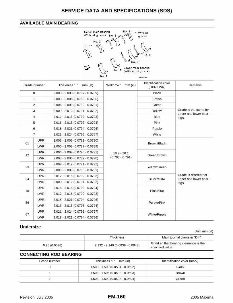
EM-160Revision: July 2005
SERVICE DATA AND SPECIFICATIONS (SDS)
2005 Maxima
AVAILABLE MAIN BEARING
UndersizeUnit: mm (in)
CONNECTING ROD BEARING
Grade number Thickness “T” mm (in) Width “W” mm (in)Identification color
(UPR/LWR)Remarks
0 2.000 - 2.003 (0.0787 - 0.0789)
19.9 - 20.1(0.783 - 0.791)
Black
Grade is the same for upper and lower bear-ings.
1 2.003 - 2.006 (0.0789 - 0.0790) Brown
2 2.006 - 2.009 (0.0790 - 0.0791) Green
3 2.009 - 2.012 (0.0791 - 0.0792) Yellow
4 2.012 - 2.015 (0.0792 - 0.0793) Blue
5 2.015 - 2.018 (0.0793 - 0.0794) Pink
6 2.018 - 2.021 (0.0794 - 0.0796) Purple
7 2.021 - 2.024 (0.0796 - 0.0797) White
01UPR 2.003 - 2.006 (0.0789 - 0.0790)
Brown/Black
Grade is different for upper and lower bear-ings.
LWR 2.000 - 2.003 (0.0787 - 0.0789)
12UPR 2.006 - 2.009 (0.0790 - 0.0791)
Green/BrownLWR 2.003 - 2.006 (0.0789 - 0.0790)
23UPR 2.009 - 2.012 (0.0791 - 0.0792)
Yellow/GreenLWR 2.006 - 2.009 (0.0790 - 0.0791)
34UPR 2.012 - 2.015 (0.0792 - 0.0793)
Blue/YellowLWR 2.009 - 2.012 (0.0791 - 0.0792)
45UPR 2.015 - 2.018 (0.0793 - 0.0794)
Pink/BlueLWR 2.012 - 2.015 (0.0792 - 0.0793)
56UPR 2.018 - 2.021 (0.0794 - 0.0796)
Purple/PinkLWR 2.015 - 2.018 (0.0793 - 0.0794)
67UPR 2.021 - 2.024 (0.0796 - 0.0797)
White/PurpleLWR 2.018 - 2.021 (0.0794 - 0.0796)
SEM175F
Thickness Main journal diameter “Dm”
0.25 (0.0098) 2.132 - 2.140 (0.0839 - 0.0843)Grind so that bearing clearance is the specified value.
Grade number Thickness “T” mm (in) Identification color (mark)
0 1.500 - 1.503 (0.0591 - 0.0592) Black
1 1.503 - 1.506 (0.0592 - 0.0593) Brown
2 1.506 - 1.509 (0.0593 - 0.0594) Green

SERVICE DATA AND SPECIFICATIONS (SDS)
EM-161
C
D
E
F
G
H
I
J
K
L
M
A
EM
Revision: July 2005 2005 Maxima
UndersizeUnit: mm (in)
MISCELLANEOUS COMPONENTSUnit: mm (in)
*: Total indicator reading
BEARING CLEARANCEUnit: mm (in)
*: Actual clearance
Thickness Crank pin journal diameter “Dp”
0.25 (0.0098) 1.626 - 1.634 (0.0640 - 0.0643)Grind so that bearing clearance is the specified value.
Flywheel deflection [TIR]* - Standard Less than 0.45 (0.0177)
Flywheel deflection [TIR]* - Limit 1.3 (0.051)
Drive plate runout [TIR]* Less than 0.15 (0.0059)
Flywheel movement in rotation direction Less than 24 (0.94)
Main bearing clearanceStandard 0.035 - 0.045 (0.0014 - 0.0018)*
Limit 0.065 (0.0026)
Connecting rod bearing clear-ance
Standard 0.034 - 0.059 (0.0013 - 0.0023)*
Limit 0.070 (0.0028)

EM-162Revision: July 2005
SERVICE DATA AND SPECIFICATIONS (SDS)
2005 Maxima