Embed Size (px)
Citation preview
Section
Selection Guides .................................. E-2
General Purpose Relays
• RR Series . . . . . . . . . . . . . . . . . . . . . E-6• RH Series . . . . . . . . . . . . . . . . . . . . E-10• RM Series . . . . . . . . . . . . . . . . . . . . E-16• RY Series . . . . . . . . . . . . . . . . . . . . E-19
Latching Relays
• RR2KP Series . . . . . . . . . . . . . . . . . E-23• RH2L Series . . . . . . . . . . . . . . . . . . E-26• RY2KS Series . . . . . . . . . . . . . . . . . E-29• RY2L Series . . . . . . . . . . . . . . . . . . E-32
E
Relays
Relays
Selection Guide
E-2
www.idec.com
USA: (800) 262-IDEC or (408) 747-0550, Canada (888) 317-IDEC
E
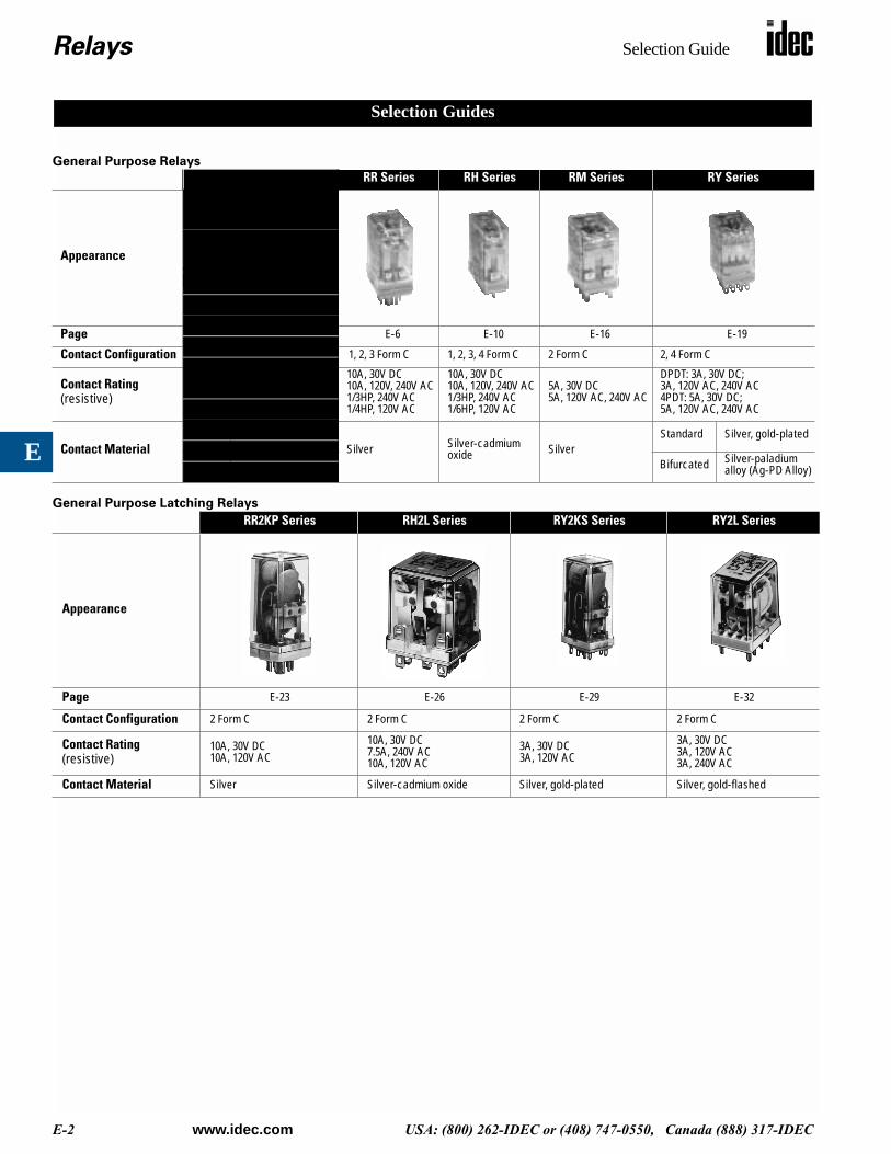
General Purpose Relays
General Purpose Latching Relays
RR Series RH Series RM Series RY Series
Appearance
Page
E-6 E-10 E-16 E-19
Contact Configuration
1, 2, 3 Form C
1, 2, 3, 4 Form C 2 Form C 2, 4 Form C
Contact Rating
(resistive)
10A, 30V DC10A, 120V, 240V AC1/3HP, 240V AC1/4HP, 120V AC
10A, 30V DC10A, 120V, 240V AC1/3HP, 240V AC1/6HP, 120V AC
5A, 30V DC5A, 120V AC, 240V AC
DPDT: 3A, 30V DC;3A, 120V AC, 240V AC4PDT: 5A, 30V DC; 5A, 120V AC, 240V AC
Contact Material
Silver Silver-cadmium oxide Silver
Standard Silver, gold-plated
Bifurcated Silver-paladium alloy (Ag-PD Alloy)
RR2KP Series RH2L Series RY2KS Series RY2L Series
Appearance
Page
E-23 E-26 E-29 E-32
Contact Configuration
2 Form C 2 Form C 2 Form C 2 Form C
Contact Rating
(resistive)
10A, 30V DC10A, 120V AC
10A, 30V DC7.5A, 240V AC10A, 120V AC
3A, 30V DC3A, 120V AC
3A, 30V DC3A, 120V AC3A, 240V AC
Contact Material
Silver Silver-cadmium oxide Silver, gold-plated Silver, gold-flashed
Selection Guides

Relays
RR Series
E-6
www.idec.com
USA: (800) 262-IDEC or (408) 747-0550, Canada (888) 317-IDEC
E
Key features of the RR series include:• High reliability and long service life• Available in octal (8- and 11-pin) or square (11-blade) base• Options include check button for test operation, indicator light, and
side flange• DIN rail, surface and panel type sockets available for a wide range of
mounting applications
Spec
ifica
tions
Contact Material
Silver
Contact Resistance
30m
Ω
maximum (initial value)
MinimumApplicable Load
24V DC/10mA, 5V DC/20mA (reference value)
Operating Time
25ms maximum
Release Time
25ms maximum
Maximum Continuous Applied Voltage (AC/DC) at 20°C
110% of the rated voltage
Minimum Operating Voltage (AC/DC) at 20°C
80% of the rated voltage
Drop-Out Voltage (AC) at 20°C
30% of the rated voltage
Drop-Out Voltage (DC) at 20°C
15% of the rated voltage
Power Consumption
AC: approximately 3VA (50Hz), 2.5VA (60Hz)DC: approximately 1.5W
Insulation Resistance
100M
Ω
minimum (measured with 500V DC megger)
Dielectric Strength
Pin
(RR2P, RR3PA)Between live and dead parts: 1,500V AC, 1 minuteBetween contact circuit and operating coil: 1,500V AC, 1 minuteBetween contact circuits: 1,500V AC,1 minute (1,000V AC between NO-NC contacts)
Blade
(RR1BA, RR2BA, RR3B)Between live and dead parts: 2,000V AC, 1 minuteBetween contact circuit and operating coil: 2,000V AC, 1 minuteBetween contact circuits: 2,000V AC, 1 minuteBetween contacts of same polarity: 1,000V AC, 1 minute
Frequency Response
1,800 operations/hour
Temperature Rise
Coil: 85°C maximumContact: 65°C maximum
Vibration Resistance
0 to 6G (55Hz maximum)
Shock Resistance
100N (approximately 10G)
Life Expectancy
Electrical: over 500,000 operations (120V, 50/60Hz, 10A)Mechanical: over 10,000,000 operations
Operating Temperature
–30 to +70°C
Weight
RR2P: 90g, RR3P/RR3PA: 96g (approximately)RR1BA/RR2BA/RR3B: 82g (approximately)
RR Series — General Purpose Power Relays
Order standard voltages for fastest delivery. Allow extra delivery time fornon-standard voltages.
UL RecognizedFile Nos. E67770
CSA CertifiedFile No. LR35144
* Pin Style Only File No. BL951113332319** Pin Style Only (does not apply to blade style)
*
Ordering Information
RR3PA-U AC120V
Basic Part No. Coil Voltage:
–
Relays
RR Series
www.idec.com
USA: (800) 262-IDEC or (408) 747-0550, Canada (888) 317-IDEC
E-7
E
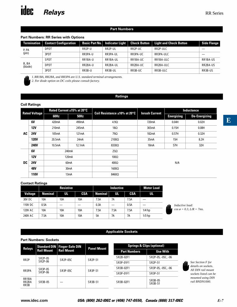
Part Numbers: RR Series with Options
Coil Ratings
Contact Ratings
Part Numbers: Sockets
Termination Contact Configuration Basic Part No. Indicator Light Check Button Light and Check Button Side Flange
P, PA (pin)
DPDT RR2P-U RR2P-UL RR2P-UC RR2P-ULC —
3PDT RR3PA-U RR3PA-UL RR3PA-UC RR3PA-ULC —
B, BA(blade)
SPDT RR1BA-U RR1BA-UL RR1BA-UC RR1BA-ULC RR1BA-US
DPDT RR2BA-U RR2BA-UL RR2BA-UC RR2BA-ULC RR2BA-US
3PDT RR3B-U RR3B-UL RR3B-UC RR3B-ULC RR3B-US
Rated VoltageRated Current ±15% at 20°C
Coil Resistance ±10% at 20°C Inrush CurrentInductance
60Hz 50Hz Energizing De-Energizing
AC
6V
420mA 490mA 4.9
Ω
720mA 0.04H 0.02H
12V
210mA 245mA 18
Ω
365mA 0.15H 0.08H
24V
105mA 121mA 79
Ω
182mA 0.57H 0.32H
120V
20.5mA 24mA 2100
Ω
35mA 15H 8.2H
240V
10.5mA 12.1mA 8330
Ω
18mA 57H 32H
DC
6V
240mA 25
Ω
N/A
12V 120mA 100Ω
24V 60mA 400Ω
48V 30mA 1600Ω
110V 13mA 8460Ω
Resistive Inductive Motor Load
Voltage Nominal UL CSA Nominal UL CSA UL
30V DC 10A 10A 10A 7.5A 7A 7.5A —
110V DC 0.5A — — 0.3A — 0.5A —
120V AC 10A 10A 10A 7.5A 7.5A 7.5A 1/4 hp
240V AC 7.5A 10A 10A 5A 7A 7A 1/3 hp
Relays Standard DIN Rail Mount
Finger-Safe DIN Rail Mount Panel Mount
Springs & Clips (optional)
Part Numbers Use With
RR2P SR2P-05SR2P-06 SR2P-05C SR2P-51
SR2B-02F1 SR2P-05, -05C, -06
SR3P-01F1 SR2P-51
RR3PA SR3P-05SR3P-06 SR3P-05C SR3P-51
SR3B-02F1 SR3P-05, -05C, -06
SR3P-01F1 SR3P-51
RR1BARR2BARR3B
SR3B-05 — SR3B-51 SR3B-02F1 SR3B-05SR3B-51
Part Numbers
1.RR1BA, RR2BA, and RR3PA are U.S. standard terminal arrangements.2. For diode option on DC coils please consult factory.
Ratings
Inductive load:cos ø = 0.3, L/R = 7ms.
Applicable Sockets
See Section F for details on sockets. All DIN rail mountsockets listed can be mounted using DIN rail BNDN1000.
Relays RR Series
E-8 www.idec.com USA: (800) 262-IDEC or (408) 747-0550, Canada (888) 317-IDEC
E
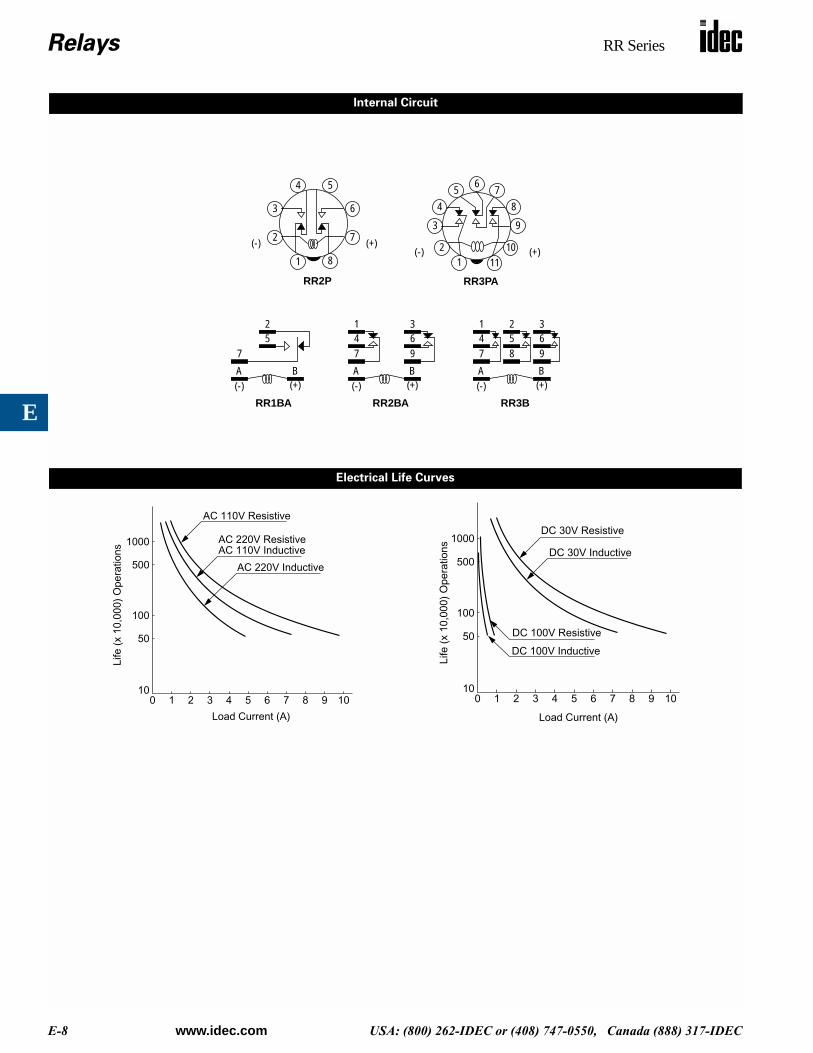
Internal Circuit
52
7
BA(-) (+)
1
2
6
5
7
8
4
3
(+)(-)
12
65 7
84
3
(+)(-)
9
1011
RR2P RR3PA
RR1BA
41
7
BA(-) (+)
RR2BA
63
941
7
BA(-) (+)
RR3B
63
952
8
Electrical Life Curves
0 1 2 3 4 5 6 7 8 9 1010
50
100
500
1000
AC 110V Resistive
AC 220V Inductive
AC 220V ResistiveAC 110V Inductive
Load Current (A)
Life
(x
10,0
00)
Ope
ratio
ns
0 1 2 3 4 5 6 7 8 9 1010
50
100
500
1000DC 30V Resistive
DC 100V Inductive
DC 100V Resistive
DC 30V Inductive
Load Current (A)
Life
(x
10,0
00)
Ope
ratio
ns
Relays RR Series
www.idec.com USA: (800) 262-IDEC or (408) 747-0550, Canada (888) 317-IDEC E-9
E
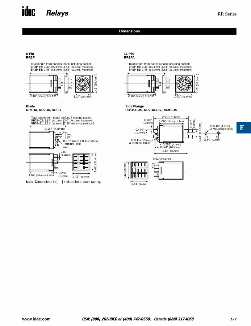
Dimensions
2.18" (56mm) or Less
Total length from panel surface including socket:SR2P-05: 3.33" (85.3mm) [3.44" (88.3mm) maximum]SR2P-51: 2.48" (63.6mm) [2.68" (68.7mm) maximum]
1.14" (29.3mm)1.
42"
(36.
4mm
)
8-PinRR2P
2.18" (56mm) or Less
Total length from panel surface including socket:SR2P-05: 3.33" (85.3mm) [3.44" (88.3mm) maximum]SR2P-51: 2.48" (63.6mm) [2.68" (68.7mm) maximum]
1.42" (36.4mm)
1.42
" (3
6.4m
m)
11-PinRR3PA
Total length from panel surface including socket:
0.187" (4.8mm)
SR3B-02: 2.87" (73.7mm) [3.0" (76.7mm) maximum]SR3B-51: 2.21" (56.6mm) [2.36" (60.6mm) maximum]
0.02"
1.87" (48mm) or less0.288"(7.4mm)
1.42
" (3
6.4m
m)
1.42" (36.4mm)
Note: Dimensions in [ ] include hold-down spring.
BladeRR1BA, RR2BA, RR3B
1.44" (37mm)
1.44
" (3
7mm
)
0.187"
Ø 0.117" (3mm)3 Terminal Holes
0.02" (0.51mm)
(4.8mm)
0.16
8"(4
.3m
m)
1.09" (28mm) or less
2.94" (75.4mm)
0.288" (7.4mm)0.644" (16.5mm)
2.54" (65mm)
0.64
" (1
6.4m
m)
0.444"(11.4mm)
Ø 0.18" (4.6mm)2 Mounting Holes
2.54" (65mm)
Side FlangeRR1BA-US, RR2BA-US, RR3B-US
0.078" (2mm) x 0.117" (3mm)Terminal Hole
(0.51mm)
Relays RH Series
E-10 www.idec.com USA: (800) 262-IDEC or (408) 747-0550, Canada (888) 317-IDEC
E
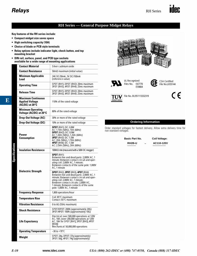
Key features of the RH series include:• Compact midget size saves space• High switching capacity (10A)• Choice of blade or PCB style terminals• Relay options include indicator light, check button, and top
mounting bracket• DIN rail, surface, panel, and PCB type sockets
available for a wide range of mounting applications
Spec
ifica
tions
Contact Material Silver cadmium oxide
Contact Resistance 50mΩ maximum (initial value)
Minimum Applicable Load
24V DC/30mA, 5V DC/100mA (reference value)
Operating Time SPDT (RH1), DPDT (RH2): 20ms maximum3PDT (RH3), 4PDT (RH4): 25ms maximum
Release Time SPDT (RH1), DPDT (RH2): 20ms maximum3PDT (RH3), 4PDT (RH4): 25ms maximum
Maximum Continuous Applied Voltage (AC/DC) at 20°C
110% of the rated voltage
Minimum Operating Voltage (AC/DC) at 20°C 80% of the rated voltage
Drop-Out Voltage (AC) 30% or more of the rated voltage
Drop-Out Voltage (DC) 10% or more of the rated voltage
Power Consumption
SPDT (RH1): DC: 0.8WAC: 1.1VA (50Hz), 1VA (60Hz)DPDT (RH2): DC: 0.9WAC: 1.4VA (50Hz), 1.2VA (60Hz)3PDT (RH3): DC: 1.5WAC: 2VA (50Hz), 1.7VA (60Hz)4PDT (RH4): DC: 1.5WAC: 2.5VA (50Hz), 2VA (60Hz)
Insulation Resistance 100MΩ min (measured with a 500V DC megger)
Dielectric Strength
SPDT (RH1)Between live and dead parts: 2,000V AC, 1 minute; Between contact circuit and oper-ating coil: 2,000V AC, 1 minute; Between contacts of the same pole: 1,000V AC, 1 minute
DPDT (RH2), 3PDT (RH3), 4PDT (RH4)Between live and dead parts: 2,000V AC, 1 minute; Between contact circuit and oper-ating coil: 2,000V AC, 1 minute; Between contact circuits: 2,000V AC, 1 minute; Between contacts of the same pole: 1,000V AC, 1 minute
Frequency Response 1,800 operations/hour
Temperature Rise Coil: 85°C maximumContact: 65°C maximum
Vibration Resistance 0 to 6G (55Hz maximum)
Shock Resistance SPDT/DPDT: 200N (approximately 20G)3PDT/4PDT: 100N (approximately 10G)
Life Expectancy
Electrical: over 500,000 operations at 120V AC, 10A; (over 200,000 operations at 120V AC, 10A for SPDT [RH1], 3PDT [RH3], 4PDT [RH4])Mechanical: 50,000,000 operations
Operating Temperature –30 to +70°C
Weight SPDT: 24g, DPDT: 37g (approximately)3PDT: 50g, 4PDT: 74g (approximately)
RH Series — General Purpose Midget Relays
Order standard voltages for fastest delivery. Allow extra delivery time fornon-standard voltages.
UL RecognizedFiles No. E67770
E59804
CSA CertifiedFile No.LR35144
File No. BL951113332319
Ordering Information
RH2B-U AC110-120V
Basic Part No. Coil Voltage:
–
Relays RH Series
www.idec.com USA: (800) 262-IDEC or (408) 747-0550, Canada (888) 317-IDEC E-11
E
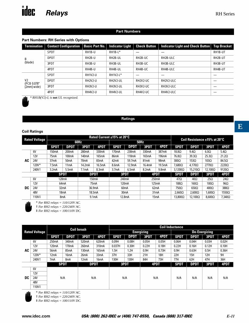
Part Numbers: RH Series with Options
Coil Ratings
Termination Contact Configuration Basic Part No. Indicator Light Check Button Indicator Light and Check Button Top Bracket
B (blade)
SPDT RH1B-U RH1B-L* — — RH1B-UT
DPDT RH2B-U RH2B-UL RH2B-UC RH2B-ULC RH2B-UT
3PDT RH3B-U RH3B-UL RH3B-UC RH3B-ULC RH3B-UT
4PDT RH4B-U RH4B-UL RH4B-UC RH4B-ULC RH4B-UT
V2(PCB 0.078" [2mm] wide)
SPDT RH1V2-U RH1V2-L* — — —
DPDT RH2V2-U RH2V2-UL RH2V2-UC RH2V2-ULC —
3PDT RH3V2-U RH3V2-UL RH3V2-UC RH3V2-ULC —
4PDT RH4V2-U RH4V2-UL RH4V2-UC RH4V2-ULC —
Rated VoltageRated Current ±15% at 20°C
Coil Resistance ±15% at 20°C60Hz 50Hz
SPDT DPDT 3PDT 4PDT SPDT DPDT 3PDT 4PDT SPDT DPDT 3PDT 4PDT
AC
6V 150mA 200mA 280mA 330mA 170mA 238mA 330mA 387mA 18.8Ω 9.4Ω 6.0Ω 5.4Ω12V 75mA 100mA 140mA 165mA 86mA 118mA 165mA 196mA 76.8Ω 39.3Ω 25.3Ω 21.2Ω24V 37mA 50mA 70mA 83mA 42mA 59.7mA 81mA 98mA 300Ω 153Ω 103Ω 84.5Ω120V* 7.5mA 11mA 14.2mA 16.5mA 8.6mA 12.9mA 16.4mA 19.5mA 7,680Ω 4,170Ω 2770Ω 2220Ω240V† 3.2mA 5.5mA 7.1mA 8.3mA 3.7mA 6.5mA 8.2mA 9.8mA 3,1200Ω 15,210Ω 12,100Ω 9120Ω
SPDT DPDT 3PDT 4PDT SPDT DPDT 3PDT 4PDT
DC
6V 128mA 150mA 240mA 250mA 47Ω 40Ω 25Ω 24Ω12V 64mA 75mA 120mA 125mA 188Ω 160Ω 100Ω 96Ω24V 32mA 36.9mA 60mA 62mA 750Ω 650Ω 400Ω 388Ω48V 18mA 18.5mA 30mA 31mA 2,660Ω 2,600Ω 1,600Ω 1550Ω110V‡ 8mA 9.1mA 12.8mA 15mA 13,800Ω 12,100Ω 8,600Ω 7,340Ω
Rated VoltageCoil Inrush
Coil InductanceEnergizing De-Energizing
SPDT DPDT 3PDT 4PDT SPDT DPDT 3PDT 4PDT SPDT DPDT 3PDT 4PDT
AC
6V 250mA 340mA 520mA 620mA 0.09H 0.08H 0.05H 0.05H 0.06H 0.04H 0.03H 0.02H12V 120mA 170mA 260mA 310mA 0.037H 0.30H 0.22H 0.18H 0.22H 0.16H 0.12H 0.10H24V 56mA 85mA 130mA 165mA 1.5H 1.2H 0.9H 0.73H 0.9H 0.63H 0.5H 0.36H120V* 12mA 16mA 26mA 33mA 37H 33H 21H 18H 22H 15H 12H 9H240V† 7mA 8mA 12mA 16mA 130H 130H 84H 73H 77H 62H 47H 36H
SPDT DPDT 3PDT 4PDT SPDT DPDT 3PDT 4PDT
DC
6V
N/A N/A N/A N/A N/A N/A N/A N/A12V24V48V110V‡
Part Numbers
* RH1B(V2)-L is not UL recognized.
Ratings
* For RH2 relays = 110/120V AC. † For RH2 relays = 220/240V AC.‡ For RH2 relays = 100/110V DC.
* For RH2 relays = 110/120V AC. † For RH2 relays = 220/240V AC.‡ For RH2 relays = 100/110V DC.
Relays RH Series
E-12 www.idec.com USA: (800) 262-IDEC or (408) 747-0550, Canada (888) 317-IDEC
E
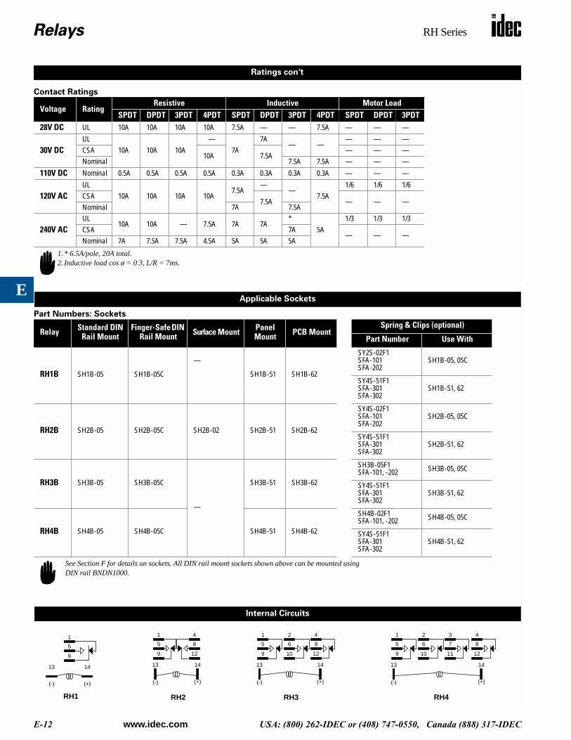
Contact Ratings
Part Numbers: Sockets
Voltage RatingResistive Inductive Motor Load
SPDT DPDT 3PDT 4PDT SPDT DPDT 3PDT 4PDT SPDT DPDT 3PDT28V DC UL 10A 10A 10A 10A 7.5A — — 7.5A — — —
30V DCUL
10A 10A 10A—
7A7A
— —— — —
CSA10A 7.5A
— — —Nominal 7.5A 7.5A — — —
110V DC Nominal 0.5A 0.5A 0.5A 0.5A 0.3A 0.3A 0.3A 0.3A — — —
120V ACUL
10A 10A 10A 10A7.5A
——
7.5A1/6 1/6 1/6
CSA7.5A — — —
Nominal 7A 7.5A
240V ACUL
10A 10A — 7.5A 7A 7A*
5A1/3 1/3 1/3
CSA 7A— — —
Nominal 7A 7.5A 7.5A 4.5A 5A 5A 5A
Relay Standard DIN Rail Mount
Finger-Safe DIN Rail Mount Surface Mount Panel
Mount PCB MountSpring & Clips (optional)
Part Number Use With
RH1B SH1B-05 SH1B-05C
—
SH1B-51 SH1B-62
SY2S-02F1SFA-101SFA-202
SH1B-05, 05C
SY4S-51F1SFA-301SFA-302
SH1B-51, 62
RH2B SH2B-05 SH2B-05C SH2B-02 SH2B-51 SH2B-62
SY4S-02F1SFA-101SFA-202
SH2B-05, 05C
SY4S-51F1SFA-301SFA-302
SH2B-51, 62
RH3B SH3B-05 SH3B-05C
—
SH3B-51 SH3B-62
SH3B-05F1SFA-101, -202 SH3B-05, 05C
SY4S-51F1SFA-301SFA-302
SH3B-51, 62
RH4B SH4B-05 SH4B-05C SH4B-51 SH4B-62
SH4B-02F1SFA-101, -202 SH4B-05, 05C
SY4S-51F1SFA-301SFA-302
SH4B-51, 62
1.* 6.5A/pole, 20A total.2. Inductive load cos ø = 0.3, L/R = 7ms.
Applicable Sockets
Ratings con’t
See Section F for details on sockets. All DIN rail mount sockets shown above can be mounted using DIN rail BNDN1000.
Internal Circuits
85
1
9
1413
(-) (+)
RH1
5
1
9
1413
(-) (+)
RH2
4
12
65
1
9
1413
(-) (+)
RH3
2
10
8
4
12
65
1
9
1413
(-) (+)
RH4
2
10
7
3
11
8
4
12
Relays RH Series
www.idec.com USA: (800) 262-IDEC or (408) 747-0550, Canada (888) 317-IDEC E-13
E
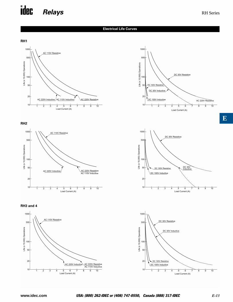
RH1
RH2
RH3 and 4
1 3 5 7 92 4 6 8 10
50
20
10
100
500
1000
AC 110V Resistive
AC 220V Inductive AC 220V ResistiveAC 110V Inductive
Load Current (A)
Life (
x 1
0,0
00)
Opera
tions
1 3 5 7 92 4 6 8 10
50
20
10
100
500
1000
DC 30V Resistive
DC 30V Inductive
DC 100V Resistive
AC 220V ResistiveDC 100V Inductive
Load Current (A)
Life
(x 1
0,0
00
) O
pe
ratio
ns
Electrical Life Curves
1 3 5 7 92 4 6 8 10
50
20
10
100
500
1000AC 110V Resistive
AC 220V Inductive AC 220V Resistive
AC 110V Inductive
Load Current (A)
Life
(x 1
0,0
00
) O
pe
ratio
ns
1 3 5 7 92 4 6 8 10
50
20
10
100
500
1000
DC 30V Resistive
DC 30V InductiveDC 100V Resistive
DC 100V Inductive
Load Current (A)
Life
(x 1
0,0
00
) O
pe
ratio
ns
1 3 5 7 92 4 6 8 10
50
20
10
100
500
1000
AC 110V Resistive
AC 220V Inductive AC 220V Resistive
AC 110V Inductive
Load Current (A)
Life
(x 1
0,0
00
) O
pe
ratio
ns
1 3 5 7 92 4 6 8 10
50
20
10
100
500
1000
DC 30V Resistive
DC 30V Inductive
DC 100V Resistive
DC 100V Inductive
Load Current (A)
Life
(x 1
0,0
00
) O
pe
ratio
ns
Relays RH Series
E-14 www.idec.com USA: (800) 262-IDEC or (408) 747-0550, Canada (888) 317-IDEC
E
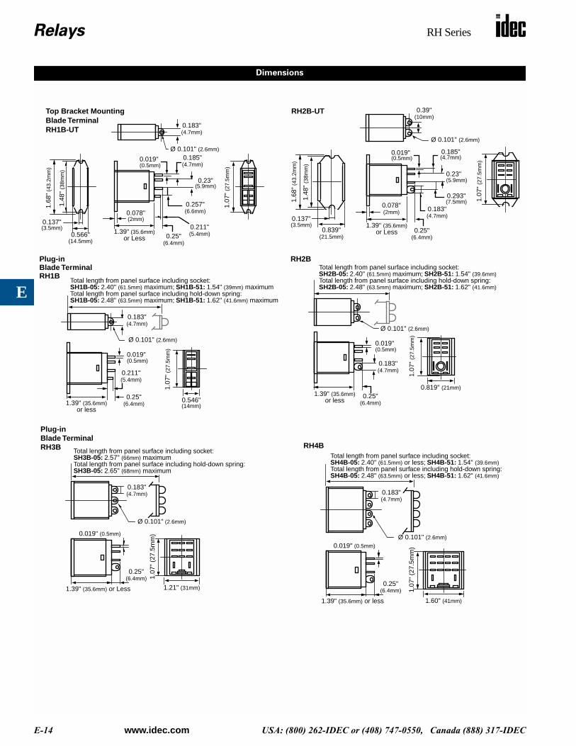
0.183"(4.7mm)
Ø 0.101" (2.6mm)
0.566"
1.48
" (3
8mm
)
1.68
" (4
3.2m
m)
0.137"(3.5mm)
0.078"(2mm)
1.39" (35.6mm)0.25"
(6.4mm)
0.211"(5.4mm)
0.257"(6.6mm)
0.019" 0.185"(4.7mm)
0.23"(5.9mm)
1.07
" (2
7.5m
m)
Top Bracket Mounting Blade TerminalRH1B-UT
0.39"(10mm)
Ø 0.101" (2.6mm)
0.137"(3.5mm)
0.839"
1.48
" (3
8mm
)
1.68
" (4
3.2m
m)
0.078"(2mm)
1.39" (35.6mm)0.25"
(6.4mm)
0.293"(7.5mm)
0.019" 0.185"(4.7mm)
0.23"(5.9mm)
0.183"(4.7mm)
1.07
" (2
7.5m
m)
RH2B-UT
(21.5mm)or Less
(0.5mm)
(14.5mm) or Less
(0.5mm)
0.183"(4.7mm)
Ø 0.101" (2.6mm)
1.39" (35.6mm)0.25"
(6.4mm)
0.211"(5.4mm)
0.019"
1.07
" (2
7.5m
m)
Total length from panel surface including socket:SH1B-05: 2.40" (61.5mm) maximum; SH1B-51: 1.54" (39mm) maximumTotal length from panel surface including hold-down spring:SH1B-05: 2.48" (63.5mm) maximum; SH1B-51: 1.62" (41.6mm) maximum
0.546"
Plug-inBlade TerminalRH1B
(0.5mm)
(14mm)or less
1.39" (35.6mm) 0.25"(6.4mm)
0.019"
0.183"(4.7mm)
1.07
" (2
7.5m
m)
Total length from panel surface including socket:SH2B-05: 2.40" (61.5mm) maximum; SH2B-51: 1.54" (39.6mm)Total length from panel surface including hold-down spring:SH2B-05: 2.48" (63.5mm) maximum; SH2B-51: 1.62" (41.6mm)
0.819" (21mm)
RH2B
Ø 0.101" (2.6mm)
or less
(0.5mm)
1.39" (35.6mm) or Less
0.25"(6.4mm)
0.019" (0.5mm)
1.07
" (2
7.5m
m)
Total length from panel surface including socket:SH3B-05: 2.57" (66mm) maximumTotal length from panel surface including hold-down spring:SH3B-05: 2.65" (68mm) maximum
1.21" (31mm)
0.183"(4.7mm)
Ø 0.101" (2.6mm)
Plug-inBlade TerminalRH3B
1.39" (35.6mm) or less
0.25"(6.4mm)
0.019" (0.5mm)
1.07
" (2
7.5m
m)
Total length from panel surface including socket:SH4B-05: 2.40" (61.5mm) or less; SH4B-51: 1.54" (39.6mm)Total length from panel surface including hold-down spring:SH4B-05: 2.48" (63.5mm) or less; SH4B-51: 1.62" (41.6mm)
1.60" (41mm)
0.183"(4.7mm)
Ø 0.101" (2.6mm)
RH4B
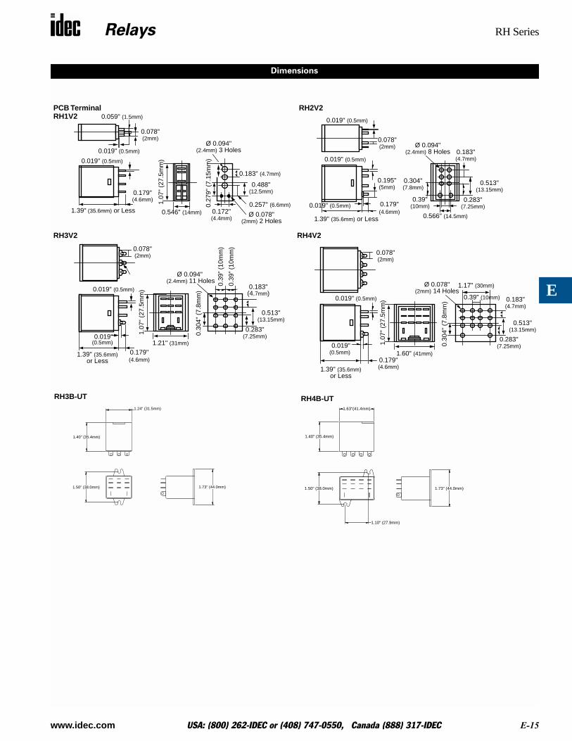
Dimensions
Relays RH Series
www.idec.com USA: (800) 262-IDEC or (408) 747-0550, Canada (888) 317-IDEC E-15
E
Dimensions
1.39" (35.6mm) or Less
0.179"(4.6mm)
0.019" (0.5mm)
0.019" (0.5mm)
0.019" (0.5mm)
0.078"(2mm)
0.195"(5mm)
0.39"(10mm)
0.566" (14.5mm)
0.304"(7.8mm)
Ø 0.094"(2.4mm) 8 Holes 0.183"
(4.7mm)
0.513"(13.15mm)
0.283"(7.25mm)
RH2V2
1.39" (35.6mm)
0.179"(4.6mm)
0.019" (0.5mm)
1.07
" (2
7.5m
m)
1.60" (41mm)
0.078"(2mm)
0.019"
0.39" (10mm)
1.17" (30mm)
0.30
4" (
7.8m
m)
Ø 0.078"(2mm) 14 Holes
0.183"(4.7mm)
0.283"(7.25mm)
0.513"(13.15mm)
RH4V2
or Less
(0.5mm)
0.078"(2mm)
1.39" (35.6mm) or Less
0.179"(4.6mm)
0.019" (0.5mm)1.
07"
(27.
5mm
)
0.546" (14mm)
0.059" (1.5mm)
0.019" (0.5mm)Ø 0.094"
(2.4mm) 3 Holes
0.27
9" (
7.15
mm
)0.172"(4.4mm)
Ø 0.078"(2mm) 2 Holes
0.257" (6.6mm)
0.488"(12.5mm)
0.183" (4.7mm)
PCB TerminalRH1V2
1.39" (35.6mm) 0.179"(4.6mm)
0.019" (0.5mm)
1.07
" (2
7.5m
m)
1.21" (31mm)
0.078"(2mm)
0.019" 0.30
4" (
7.8m
m)
Ø 0.094" (2.4mm) 11 Holes 0.
39” (
10m
m)
0.39
” (10
mm
)
0.283"(7.25mm)
0.513"(13.15mm)
0.183"(4.7mm)
RH3V2
or Less
(0.5mm)
1.24" (31.5mm)
1.40" (35.4mm)
1.50" (38.0mm) 1.73" (44.0mm)
1.63"(41.4mm)
1.40" (35.4mm)
1.50" (38.0mm)
1.10" (27.9mm)
1.73" (44.0mm)
RH3B-UT RH4B-UT
Relays RM Series
E-16 www.idec.com USA: (800) 262-IDEC or (408) 747-0550, Canada (888) 317-IDEC
E
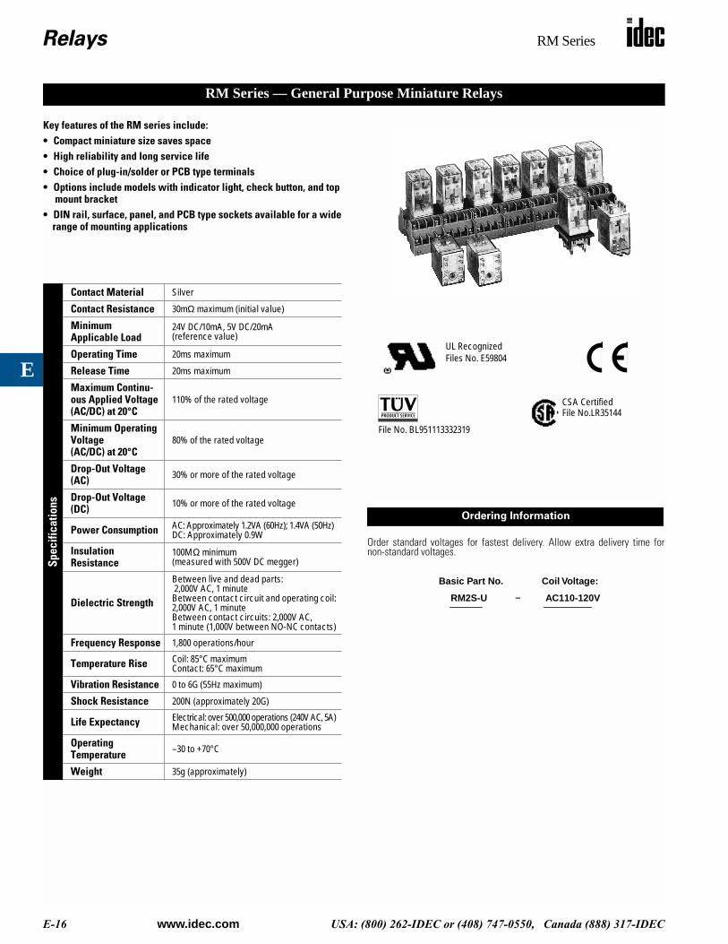
Key features of the RM series include:• Compact miniature size saves space• High reliability and long service life• Choice of plug-in/solder or PCB type terminals• Options include models with indicator light, check button, and top
mount bracket • DIN rail, surface, panel, and PCB type sockets available for a wide
range of mounting applications
Spec
ifica
tions
Contact Material Silver
Contact Resistance 30mΩ maximum (initial value)
MinimumApplicable Load
24V DC/10mA, 5V DC/20mA (reference value)
Operating Time 20ms maximum
Release Time 20ms maximum
Maximum Continu-ous Applied Voltage (AC/DC) at 20°C
110% of the rated voltage
Minimum Operating Voltage (AC/DC) at 20°C
80% of the rated voltage
Drop-Out Voltage (AC) 30% or more of the rated voltage
Drop-Out Voltage (DC) 10% or more of the rated voltage
Power Consumption AC: Approximately 1.2VA (60Hz); 1.4VA (50Hz)DC: Approximately 0.9W
Insulation Resistance
100MΩ minimum (measured with 500V DC megger)
Dielectric Strength
Between live and dead parts: 2,000V AC, 1 minuteBetween contact circuit and operating coil: 2,000V AC, 1 minuteBetween contact circuits: 2,000V AC,1 minute (1,000V between NO-NC contacts)
Frequency Response 1,800 operations/hour
Temperature Rise Coil: 85°C maximumContact: 65°C maximum
Vibration Resistance 0 to 6G (55Hz maximum)
Shock Resistance 200N (approximately 20G)
Life Expectancy Electrical: over 500,000 operations (240V AC, 5A)Mechanical: over 50,000,000 operations
Operating Temperature –30 to +70°C
Weight 35g (approximately)
RM Series — General Purpose Miniature Relays
Order standard voltages for fastest delivery. Allow extra delivery time fornon-standard voltages.
UL RecognizedFiles No. E59804
CSA CertifiedFile No.LR35144
File No. BL951113332319
Ordering Information
RM2S-U AC110-120V
Basic Part No. Coil Voltage:
–
Relays RM Series
www.idec.com USA: (800) 262-IDEC or (408) 747-0550, Canada (888) 317-IDEC E-17
E
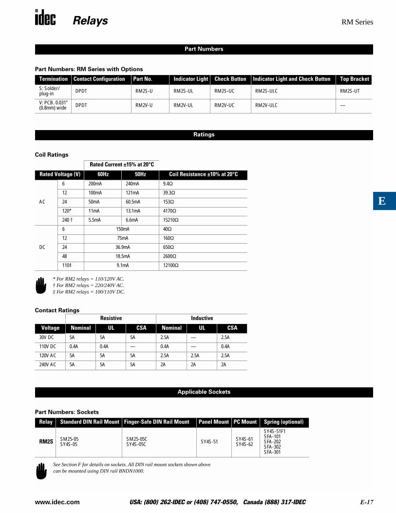
Part Numbers: RM Series with Options
Coil Ratings
Contact Ratings
Part Numbers: Sockets
Termination Contact Configuration Part No. Indicator Light Check Button Indicator Light and Check Button Top Bracket
S: Solder/plug-in DPDT RM2S-U RM2S-UL RM2S-UC RM2S-ULC RM2S-UT
V: PCB. 0.031"(0.8mm) wide DPDT RM2V-U RM2V-UL RM2V-UC RM2V-ULC —
Rated Current ±15% at 20°C
Rated Voltage (V) 60Hz 50Hz Coil Resistance ±10% at 20°C
AC
6 200mA 240mA 9.4Ω
12 100mA 121mA 39.3Ω
24 50mA 60.5mA 153Ω
120* 11mA 13.1mA 4170Ω
240 † 5.5mA 6.6mA 15210Ω
DC
6 150mA 40Ω
12 75mA 160Ω
24 36.9mA 650Ω
48 18.5mA 2600Ω
110‡ 9.1mA 12100Ω
Resistive Inductive
Voltage Nominal UL CSA Nominal UL CSA
30V DC 5A 5A 5A 2.5A — 2.5A
110V DC 0.4A 0.4A — 0.4A — 0.4A
120V AC 5A 5A 5A 2.5A 2.5A 2.5A
240V AC 5A 5A 5A 2A 2A 2A
Relay Standard DIN Rail Mount Finger-Safe DIN Rail Mount Panel Mount PC Mount Spring (optional)
RM2S SM25-05SY4S-05
SM25-05CSY4S-05C SY4S-51 SY4S-61
SY4S-62
SY4S-51F1SFA-101SFA-202SFA-302SFA-301
Part Numbers
Ratings
* For RM2 relays = 110/120V AC.† For RM2 relays = 220/240V AC.‡ For RM2 relays = 100/110V DC.
Applicable Sockets
See Section F for details on sockets. All DIN rail mount sockets shown above can be mounted using DIN rail BNDN1000.
Relays RM Series
E-18 www.idec.com USA: (800) 262-IDEC or (408) 747-0550, Canada (888) 317-IDEC
E
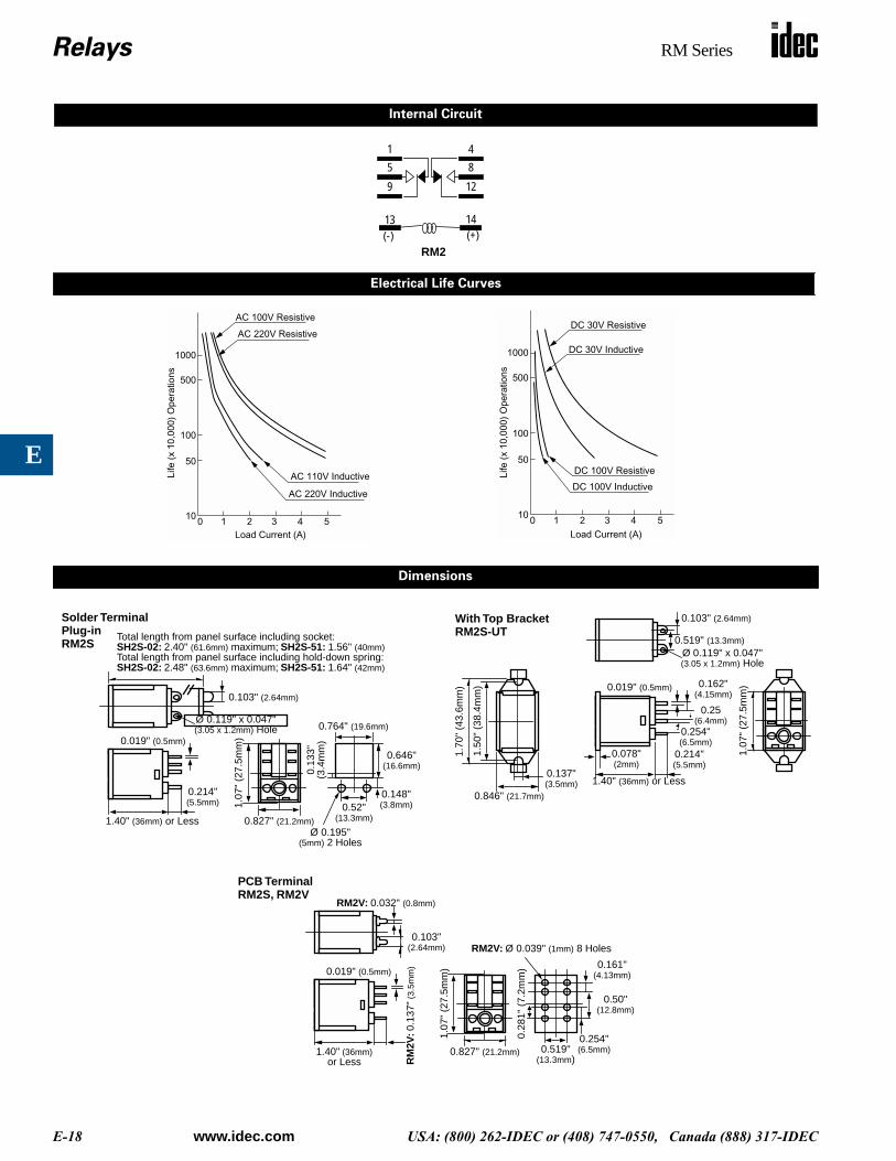
Internal Circuit
85
1
9
1413(-) (+)
4
12
RM2
Electrical Life Curves
10 3 52 4
50
100
500
1000
10
AC 100V Resistive
AC 220V Inductive
AC 220V Resistive
AC 110V Inductive
Load Current (A)
Life
(x
10,0
00)
Ope
ratio
ns
10 3 52 4
50
100
500
1000
10
DC 30V Resistive
DC 30V Inductive
DC 100V Resistive
DC 100V Inductive
Load Current (A)
Life
(x
10,0
00)
Ope
ratio
ns
Dimensions
1.40" (36mm) or Less
0.214"(5.5mm)
0.019" (0.5mm)
1.07
" (2
7.5m
m)
Total length from panel surface including socket:SH2S-02: 2.40" (61.6mm) maximum; SH2S-51: 1.56" (40mm)Total length from panel surface including hold-down spring:SH2S-02: 2.48" (63.6mm) maximum; SH2S-51: 1.64" (42mm)
0.827" (21.2mm)
Ø 0.119" x 0.047"
0.103" (2.64mm)
(3.05 x 1.2mm) Hole 0.764" (19.6mm)
0.13
3"(3
.4m
m)
0.646"(16.6mm)
0.148"(3.8mm)0.52"
(13.3mm)
Ø 0.195"(5mm) 2 Holes
Solder TerminalPlug-inRM2S
0.137"(3.5mm)
0.846" (21.7mm)
1.50
" (3
8.4m
m)
1.70
" (4
3.6m
m)
Ø 0.119" x 0.047"
0.103" (2.64mm)
(3.05 x 1.2mm) Hole
0.519" (13.3mm)
1.40" (36mm) or Less
0.214"(5.5mm)
0.019" (0.5mm)
1.07
" (2
7.5m
m)
0.078"(2mm)
0.162"(4.15mm)
0.25(6.4mm)
0.254"(6.5mm)
With Top BracketRM2S-UT
1.40" (36mm)
RM
2V: 0
.137
" (3
.5m
m)0.019" (0.5mm)
1.07
" (2
7.5m
m)
0.827" (21.2mm)
RM2V: 0.032" (0.8mm)
0.103"(2.64mm)
or Less0.519"
(13.3mm)
0.28
1" (
7.2m
m)
RM2V: Ø 0.039" (1mm) 8 Holes
0.161"(4.13mm)
0.254"(6.5mm)
0.50"(12.8mm)
PCB TerminalRM2S, RM2V
Relays RY Series
www.idec.com USA: (800) 262-IDEC or (408) 747-0550, Canada (888) 317-IDEC E-19
E
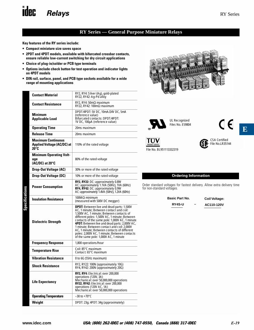
Key features of the RY series include:• Compact miniature size saves space• 2PDT and 4PDT models, available with bifurcated crossbar contacts,
ensure reliable low-current switching for dry circuit applications• Choice of plug-in/solder or PCB type terminals• Options include check button for test operation and indicator lights
on 4PDT models• DIN rail, surface, panel, and PCB type sockets available for a wide
range of mounting applications
Spec
ifica
tions
Contact Material RY2, RY4: Silver (Ag), gold-platedRY22, RY42: Ag-Pd alloy
Contact Resistance RY2, RY4: 50mΩ maximumRY22, RY42: 100mΩ maximum
MinimumApplicable Load
DPDT/4PDT: 5V DC, 10mA/24V DC, 5mA (reference value)Bifurcated contacts: DPDT/4PDT: 1V DC, 100µA (reference value)
Operating Time 20ms maximum
Release Time 20ms maximum
Maximum Continuous Applied Voltage (AC/DC) at 20°C
110% of the rated voltage
Minimum Operating Volt-age (AC/DC) at 20°C
80% of the rated voltage
Drop-Out Voltage (AC) 30% or more of the rated voltage
Drop-Out Voltage (DC) 10% or more of the rated voltage
Power ConsumptionRY2, RY22: DC: approximately 0.8WAC: approximately 1.1VA (50Hz), 1VA (60Hz)RY4, RY42: DC: approximately 0.9WAC: approximately 1.4VA (50Hz), 1.2VA (60Hz)
Insulation Resistance 100MΩ minimum(measured with 500V DC megger)
Dielectric Strength
DPDT: Between live and dead parts: 1,500V AC, 1 minute; Between contact and coil: 1,500V AC, 1 minute; Between contacts of different poles: 1,500V AC, 1 minute; Between contacts of the same pole: 1,000V AC, 1 minute4PDT: Between live and dead parts: 2,000V AC, 1 minute; Between contact and coil: 2,000V AC, 1 minute; Between contacts of different poles: 2,000V AC, 1 minute; Between contacts of the same pole: 1,000V AC, 1 minute
Frequency Response 1,800 operations/hour
Temperature Rise Coil: 85°C maximumContact: 65°C maximum
Vibration Resistance 0 to 6G (55Hz maximum)
Shock Resistance RY2, RY22: 100N (approximately 10G)RY4, RY42: 200N (approximately 20G)
Life Expectancy
RY2, RY4: Electrical: over 200,000 operations (120V, 3A)Mechanical: over 50,000,000 operationsRY22, RY42: Electrical: over 200,000 operations (120V AC, 1A)Mechanical: over 50,000,000 operations
Operating Temperature –30 to +70°C
Weight DPDT: 23g; 4PDT: 34g (approximately)
RY Series — General Purpose Miniature Relays
Order standard voltages for fastest delivery. Allow extra delivery timefor non-standard voltages.
UL RecognizedFiles No. E59804
CSA CertifiedFile No.LR35144
File No. BL951113332319
Ordering Information
RY4S-U AC110-120V
Basic Part No. Coil Voltage:
–
Relays RY Series
E-20 www.idec.com USA: (800) 262-IDEC or (408) 747-0550, Canada (888) 317-IDEC
E
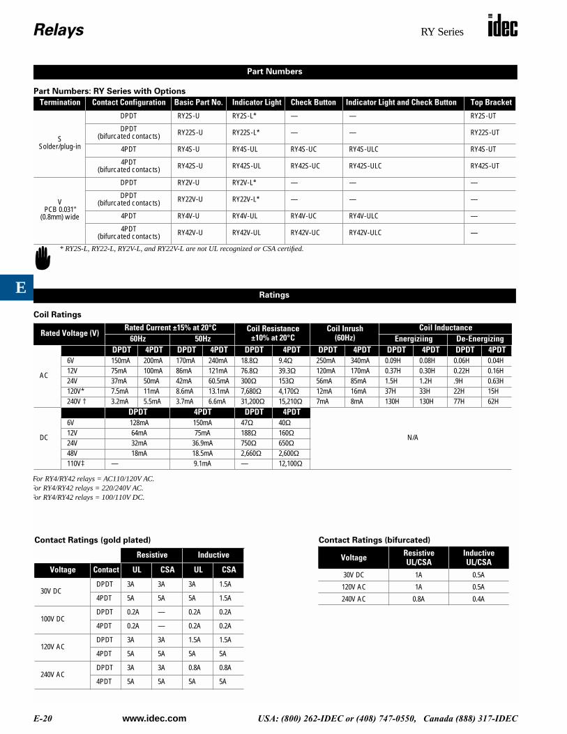
Part Numbers: RY Series with Options
Coil Ratings
Termination Contact Configuration Basic Part No. Indicator Light Check Button Indicator Light and Check Button Top Bracket
SSolder/plug-in
DPDT RY2S-U RY2S-L* — — RY2S-UT
DPDT(bifurcated contacts) RY22S-U RY22S-L* — — RY22S-UT
4PDT RY4S-U RY4S-UL RY4S-UC RY4S-ULC RY4S-UT
4PDT(bifurcated contacts) RY42S-U RY42S-UL RY42S-UC RY42S-ULC RY42S-UT
VPCB 0.031"
(0.8mm) wide
DPDT RY2V-U RY2V-L* — — —
DPDT(bifurcated contacts) RY22V-U RY22V-L* — — —
4PDT RY4V-U RY4V-UL RY4V-UC RY4V-ULC —
4PDT(bifurcated contacts) RY42V-U RY42V-UL RY42V-UC RY42V-ULC —
Rated Voltage (V)Rated Current ±15% at 20°C Coil Resistance
±10% at 20°CCoil Inrush
(60Hz)Coil Inductance
60Hz 50Hz Energiziing De-Energizing
AC
DPDT 4PDT DPDT 4PDT DPDT 4PDT DPDT 4PDT DPDT 4PDT DPDT 4PDT6V 150mA 200mA 170mA 240mA 18.8Ω 9.4Ω 250mA 340mA 0.09H 0.08H 0.06H 0.04H12V 75mA 100mA 86mA 121mA 76.8Ω 39.3Ω 120mA 170mA 0.37H 0.30H 0.22H 0.16H24V 37mA 50mA 42mA 60.5mA 300Ω 153Ω 56mA 85mA 1.5H 1.2H .9H 0.63H120V* 7.5mA 11mA 8.6mA 13.1mA 7,680Ω 4,170Ω 12mA 16mA 37H 33H 22H 15H240V † 3.2mA 5.5mA 3.7mA 6.6mA 31,200Ω 15,210Ω 7mA 8mA 130H 130H 77H 62H
DC
DPDT 4PDT DPDT 4PDT
N/A
6V 128mA 150mA 47Ω 40Ω12V 64mA 75mA 188Ω 160Ω24V 32mA 36.9mA 750Ω 650Ω48V 18mA 18.5mA 2,660Ω 2,600Ω110V‡ — 9.1mA — 12,100Ω
Part Numbers
* RY2S-L, RY22-L, RY2V-L, and RY22V-L are not UL recognized or CSA certified.
Ratings
For RY4/RY42 relays = AC110/120V AC. For RY4/RY42 relays = 220/240V AC.For RY4/RY42 relays = 100/110V DC.
Contact Ratings (gold plated)
Resistive Inductive
Voltage Contact UL CSA UL CSA
30V DCDPDT 3A 3A 3A 1.5A
4PDT 5A 5A 5A 1.5A
100V DCDPDT 0.2A — 0.2A 0.2A
4PDT 0.2A — 0.2A 0.2A
120V ACDPDT 3A 3A 1.5A 1.5A
4PDT 5A 5A 5A 5A
240V ACDPDT 3A 3A 0.8A 0.8A
4PDT 5A 5A 5A 5A
Contact Ratings (bifurcated)
Voltage ResistiveUL/CSA
InductiveUL/CSA
30V DC 1A 0.5A
120V AC 1A 0.5A
240V AC 0.8A 0.4A
Relays RY Series
www.idec.com USA: (800) 262-IDEC or (408) 747-0550, Canada (888) 317-IDEC E-21
E
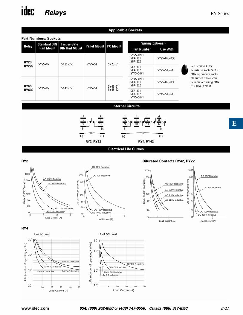
Part Numbers: Sockets
RY2 Bifurated Contacts RY42, RY22
RY4
Relay Standard DIN Rail Mount
Finger-Safe DIN Rail Mount Panel Mount PC Mount
Spring (optional)
Part Number Use With
RY2SRY22S SY2S-05 SY2S-05C SY2S-51 SY2S-61
SY2S-02F1SFA-101SFA-202
SY2S-05, -05C
SFA-301SFA-302SY4S-51F1
SY2S-51, -61
RY4SRY42S SY4S-05 SY4S-05C SY4S-51 SY4S-61
SY4S-62
SY4S-02F1SFA-101SFA-202
SY2S-05, -05C
SFA-301SFA-302SY4S-51F1
SY4S-51, -61
Applicalble Sockets
See Section F for details on sockets. All DIN rail mount sock-ets shown above can be mounted using DIN rail BNDN1000.
Internal Circuits
851
91413
(-) (+)
4
1265
1
91413
(-) (+)
RY4, RY42
2
1073
1184
12
RY2, RY22
Electrical Life Curves
0 1
50
100
500
1000
20
10
2 3
AC 110V Resistive
AC 220V Inductive
AC 220V Resistive
AC 110V Inductive
Load Current (A)
Life
(x 1
0,0
00
) O
pe
ratio
ns
0 5
50
100
500
1000
20
102 3
DC 30V Resistive
DC 30V Inductive
DC 100V ResistiveDC 100V Inductive
Load Current (A)
Life
(x
10,0
00)
Ope
ratio
ns
1
50
100
500
1000
20
10
AC 110V Resistive
AC 220V Inductive
AC 220V Resistive
AC 110V Inductive
Load Current (A)
Life
(x 1
0,0
00
) O
pe
ratio
ns
1
50
100
500
1000
20
10
DC 30V Resistive
DC 30V Inductive
DC 100V Resistive
DC 100V Inductive
Load Current (A)
Life
(x
10,0
00)
Ope
ratio
ns
1A 2A 3A 4A 5A
107
106
105
104
Load Current (A)
Life
(n
um
be
r o
f o
pe
ratin
g c
ycle
s)
RY4 AC Load
250V AC Inductive
120V AC Inductive
240V AC Resistive
120V AC Resistive
1A 2A 3A 4A 5A
107
106
105
Load Current (A)
Life
(n
um
be
r o
f o
pe
ratin
g c
ycle
s)
RY4 DC Load
104
30V DC Resistive
30V DC Inductive
110V DC Resistive110V DC Inductive
Relays RY Series
E-22 www.idec.com USA: (800) 262-IDEC or (408) 747-0550, Canada (888) 317-IDEC
E
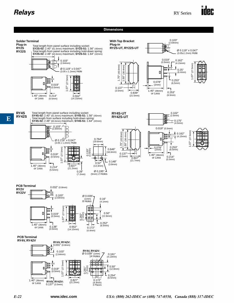
Total length from panel surface including socket:SY2S-02: 2.40" (61.6mm) maximum; SY2S-51: 1.56" (40mm)Total length from panel surface including hold-down spring:SY2S-02: 2.48" (63.6mm) maximum; SY2S-51: 1.64" (42mm)
Ø 0.119" x 0.047"
1.40" (36mm)
0.019"
or Less
1.07
” (27
.5m
m)
0.552"0.214"(5.5mm)
Solder TerminalPlug-inRY2S
0.103"(2.64mm)
Ø 0.119" x 0.047"
0.137"(3.5mm)
0.839"
1.50
" (3
8.4m
m)
1.70
" (4
3.6m
m)
0.078"(2mm)
1.40" (36mm)0.253"(6.5mm)
0.253"(6.5mm)
0.019" 0.162"(4.15mm)
0.25"(6.4mm)
1.07
” (27
.5m
m)
(3.05x1.2mm) Hole
With Top BracketPlug-inRY2S-UT, RY22S-UT
Total length from panel surface including socket:SY4S-02: 2.40" (61.6mm) maximum; SY4S-51: 1.56" (40mm)Total length from surface including hold-down spring:SY4S-02: 2.48" (63.6mm) maximum; SY4S-51: 1.64" (42mm)
0.103"(2.64mm)
Ø 0.119" x 0.047"
1.40" (36mm)
0.019"
1.07
" (2
7.5m
m)
0.827"or Less
0.764"
0.13
3"(3
.4m
m) 0.646"
(16.6mm)
0.148"(3.8mm)0.52"
(13.3mm)
Ø 0.195"(5mm) 2 Holes
0.214"(5.5mm)
0.28"
RY4S 0.102"(2.6mm)
1.40" (36mm)
0.019" (0.5mm)
1.07
" (2
7.5m
m)
or Less 0.214"(5.5mm)
0.175"
0.137"(3.5mm)
0.847"
1.50
" (3
8.4m
m)
1.70
" (4
3.6m
m)
0.078"(2mm)
RY4S-UT
0.032" (0.8mm)
0.103"(2.64mm)
1.40" (36mm)0.138"(3.5mm)
0.019"
1.07
" (2
7.5m
m)
0.552"
Ø 0.039"(1mm)
0.28
2"
0.172"(4.4mm)
0.252"
0.50"(12.8mm)
0.16"
PCB TerminalRY2V
1.40" (36mm)
0.019"
1.07
" (2
7.5m
m)
0.827"
RY4V, RY42V:
0.103"(2.64mm)
or Less
0.28
1"
RY4V, RY42V:0.161"
(4.13mm)
0.254"(6.5mm)
0.50"(12.8mm)
RY4V, RY42V:0.137" (3.5mm)
0.172"(4.4mm)
PCB TerminalRY4V, RY42V
0.103"
0.162"(4.15mm)
0.253"(6.5mm)
(3.05 x 1.2mm) Hole
RY42S
RY22S
RY42S-UT
(4.1mm)
RY22V
(21.5mm)or Less
(0.5mm)
(21.7mm)
(4.5mm)
(0.5mm)
(21.2mm)
(7.2mm)
(19.6mm)
Ø 0.039" (1mm)14 Holes
3 Places
(7.2
mm
)
(21.2mm)
(0.5mm)
0.031" (0.8mm)
or Less
(0.5mm)
(14.15mm)
(7.2
mm
)
(6.5mm)
8 Holes
(14.15mm)
(2.64mm)
(3.05 x 1.2mm) Hole
(0.5mm)
Dimensions
Relays RR2KP Series
www.idec.com USA: (800) 262-IDEC or (408) 747-0550, Canada (888) 317-IDEC E-23
E
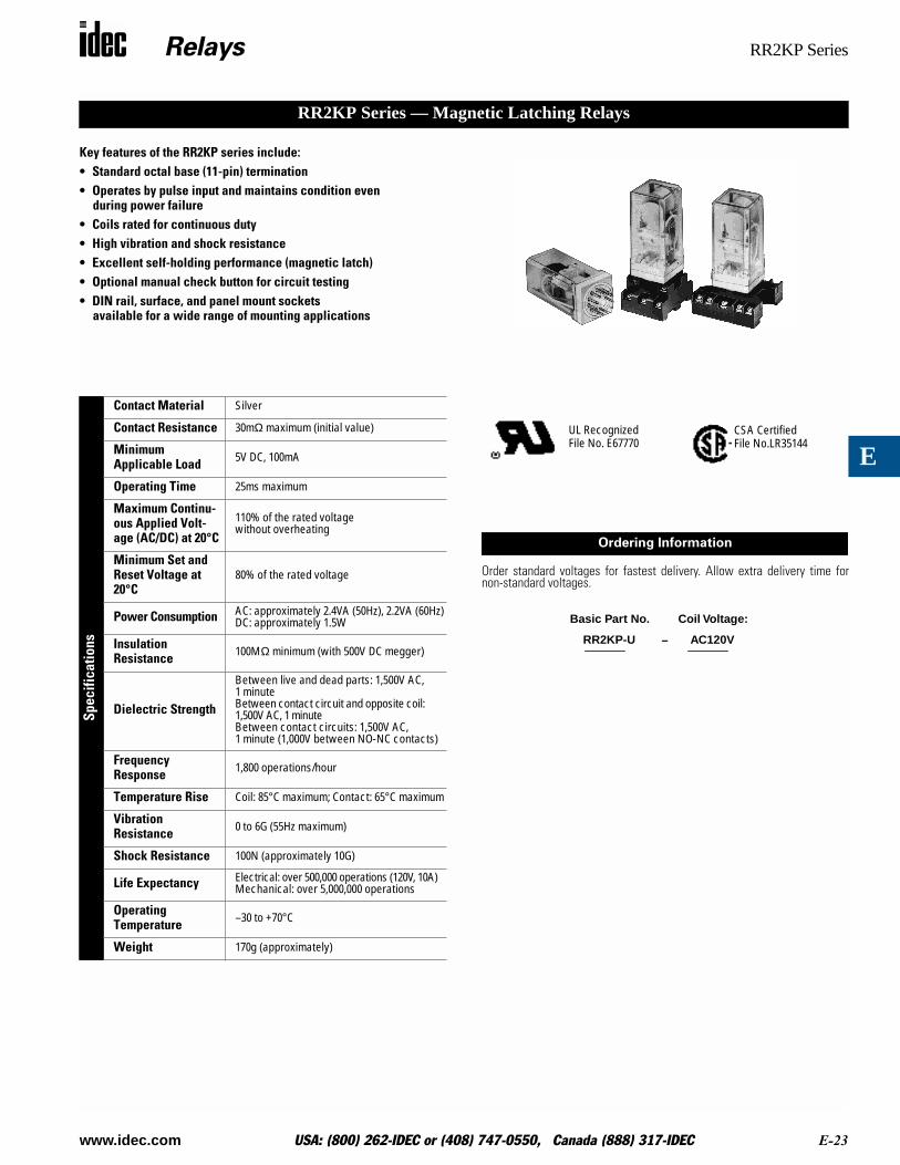
Key features of the RR2KP series include:• Standard octal base (11-pin) termination• Operates by pulse input and maintains condition even
during power failure• Coils rated for continuous duty• High vibration and shock resistance• Excellent self-holding performance (magnetic latch)• Optional manual check button for circuit testing• DIN rail, surface, and panel mount sockets
available for a wide range of mounting applications
Spec
ifica
tions
Contact Material Silver
Contact Resistance 30mΩ maximum (initial value)
MinimumApplicable Load 5V DC, 100mA
Operating Time 25ms maximum
Maximum Continu-ous Applied Volt-age (AC/DC) at 20°C
110% of the rated voltage without overheating
Minimum Set and Reset Voltage at 20°C
80% of the rated voltage
Power Consumption AC: approximately 2.4VA (50Hz), 2.2VA (60Hz)DC: approximately 1.5W
InsulationResistance 100MΩ minimum (with 500V DC megger)
Dielectric Strength
Between live and dead parts: 1,500V AC, 1 minuteBetween contact circuit and opposite coil: 1,500V AC, 1 minuteBetween contact circuits: 1,500V AC, 1 minute (1,000V between NO-NC contacts)
Frequency Response 1,800 operations/hour
Temperature Rise Coil: 85°C maximum; Contact: 65°C maximum
Vibration Resistance 0 to 6G (55Hz maximum)
Shock Resistance 100N (approximately 10G)
Life Expectancy Electrical: over 500,000 operations (120V, 10A)Mechanical: over 5,000,000 operations
Operating Temperature –30 to +70°C
Weight 170g (approximately)
RR2KP Series — Magnetic Latching Relays
Order standard voltages for fastest delivery. Allow extra delivery time fornon-standard voltages.
CSA CertifiedFile No.LR35144
UL RecognizedFile No. E67770
Ordering Information
RR2KP-U AC120V
Basic Part No. Coil Voltage:
–
Relays RR2KP Series
E-24 www.idec.com USA: (800) 262-IDEC or (408) 747-0550, Canada (888) 317-IDEC
E
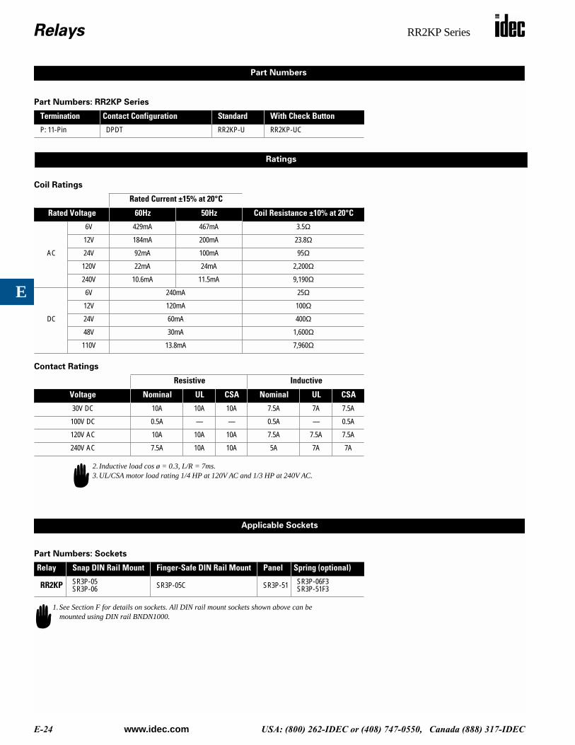
Part Numbers: RR2KP Series
Coil Ratings
Contact Ratings
Part Numbers: Sockets
Termination Contact Configuration Standard With Check Button
P: 11-Pin DPDT RR2KP-U RR2KP-UC
Rated Current ±15% at 20°C
Rated Voltage 60Hz 50Hz Coil Resistance ±10% at 20°C
AC
6V 429mA 467mA 3.5Ω
12V 184mA 200mA 23.8Ω
24V 92mA 100mA 95Ω
120V 22mA 24mA 2,200Ω
240V 10.6mA 11.5mA 9,190Ω
DC
6V 240mA 25Ω
12V 120mA 100Ω
24V 60mA 400Ω
48V 30mA 1,600Ω
110V 13.8mA 7,960Ω
Resistive Inductive
Voltage Nominal UL CSA Nominal UL CSA
30V DC 10A 10A 10A 7.5A 7A 7.5A
100V DC 0.5A — — 0.5A — 0.5A
120V AC 10A 10A 10A 7.5A 7.5A 7.5A
240V AC 7.5A 10A 10A 5A 7A 7A
Relay Snap DIN Rail Mount Finger-Safe DIN Rail Mount Panel Spring (optional)
RR2KP SR3P-05SR3P-06 SR3P-05C SR3P-51 SR3P-06F3
SR3P-51F3
Part Numbers
Ratings
2. Inductive load cos ø = 0.3, L/R = 7ms.3.UL/CSA motor load rating 1/4 HP at 120V AC and 1/3 HP at 240V AC.
Applicable Sockets
1.See Section F for details on sockets. All DIN rail mount sockets shown above can be mounted using DIN rail BNDN1000.
Relays RR2KP Series
www.idec.com USA: (800) 262-IDEC or (408) 747-0550, Canada (888) 317-IDEC E-25
E
12
65 7
84
3
(+)(-)
9
10
11
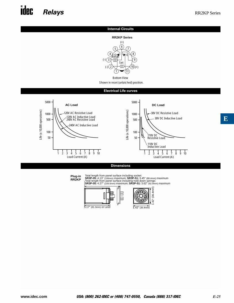
Bottom View
(+)
(-)Set
Reset
RR2KP Series
Electrical Life curves
Internal Circuits
5000
1000
500
100
50Life
(x 1
0,00
0 op
erat
ions
)
1 2 3 4 5Load Current (A)
AC Load
120V AC Resistive Load120V AC Inductive Load
240V AC Inductive Load
6 7 8 9 10
240V AC Resistive Load
5000
1000
500
100
50Life
(x 1
0,00
0 op
erat
ions
)
1 2 3 4 5Load Current (A)
DC Load
30V DC Resistive Load
6 7 8 9 10
30V DC Inductive Load
110V DCResistive Load
110V DCInductive Load
Dimensions
3.17" (81.3mm) or Less
Total length from panel surface including socket:SR3P-05: 4.13" (106mm) maximum; SR3P-51: 3.45" (88.4mm) maximumTotal length from panel surface including hold down springs:
1.42" (36.4mm)
1.42
" (3
6.4m
m)
SR3P-05: 4.27" (109.5mm) maximum; SR3P-51: 3.62" (92.9mm) maximum
Plug-inRR2KP
Shown in reset (unlatched) position.
Relays RH2L Series
E-26 www.idec.com USA: (800) 262-IDEC or (408) 747-0550, Canada (888) 317-IDEC
E
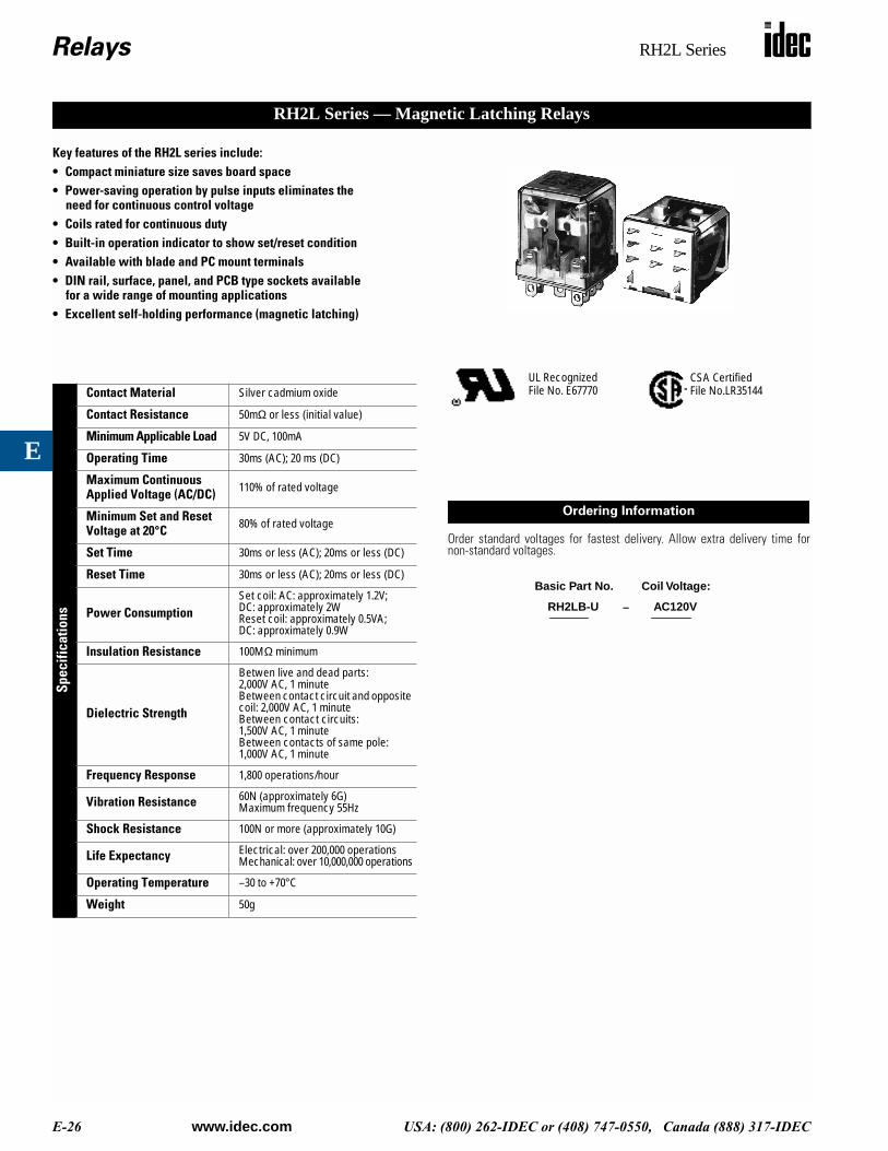
Key features of the RH2L series include:• Compact miniature size saves board space• Power-saving operation by pulse inputs eliminates the
need for continuous control voltage• Coils rated for continuous duty• Built-in operation indicator to show set/reset condition• Available with blade and PC mount terminals• DIN rail, surface, panel, and PCB type sockets available
for a wide range of mounting applications• Excellent self-holding performance (magnetic latching)
Spec
ifica
tions
Contact Material Silver cadmium oxide
Contact Resistance 50mΩ or less (initial value)
Minimum Applicable Load 5V DC, 100mA
Operating Time 30ms (AC); 20 ms (DC)
Maximum Continuous Applied Voltage (AC/DC) 110% of rated voltage
Minimum Set and Reset Voltage at 20°C 80% of rated voltage
Set Time 30ms or less (AC); 20ms or less (DC)
Reset Time 30ms or less (AC); 20ms or less (DC)
Power ConsumptionSet coil: AC: approximately 1.2V; DC: approximately 2WReset coil: approximately 0.5VA; DC: approximately 0.9W
Insulation Resistance 100MΩ minimum
Dielectric Strength
Betwen live and dead parts:2,000V AC, 1 minuteBetween contact circuit and opposite coil: 2,000V AC, 1 minuteBetween contact circuits: 1,500V AC, 1 minuteBetween contacts of same pole: 1,000V AC, 1 minute
Frequency Response 1,800 operations/hour
Vibration Resistance 60N (approximately 6G)Maximum frequency 55Hz
Shock Resistance 100N or more (approximately 10G)
Life Expectancy Electrical: over 200,000 operationsMechanical: over 10,000,000 operations
Operating Temperature –30 to +70°C
Weight 50g
RH2L Series — Magnetic Latching Relays
Order standard voltages for fastest delivery. Allow extra delivery time fornon-standard voltages.
CSA CertifiedFile No.LR35144
UL RecognizedFile No. E67770
Ordering Information
RH2LB-U AC120V
Basic Part No. Coil Voltage:
–
Relays RH2L Series
www.idec.com USA: (800) 262-IDEC or (408) 747-0550, Canada (888) 317-IDEC E-27
E
Part Numbers: RH2L Series
Coil Ratings
Contact Ratings
Part Numbers: Sockets
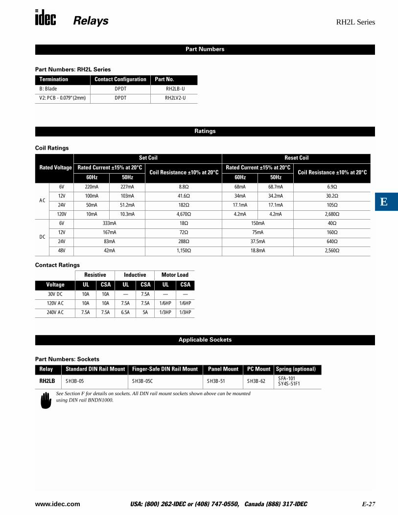
Termination Contact Configuration Part No.
B: Blade DPDT RH2LB-U
V2: PCB - 0.079" (2mm) DPDT RH2LV2-U
Rated Voltage
Set Coil Reset Coil
Rated Current ±15% at 20°CCoil Resistance ±10% at 20°C
Rated Current ±15% at 20°CCoil Resistance ±10% at 20°C
60Hz 50Hz 60Hz 50Hz
AC
6V 220mA 227mA 8.8Ω 68mA 68.7mA 6.9Ω
12V 100mA 103mA 41.6Ω 34mA 34.2mA 30.2Ω
24V 50mA 51.2mA 182Ω 17.1mA 17.1mA 105Ω
120V 10mA 10.3mA 4,670Ω 4.2mA 4.2mA 2,680Ω
DC
6V 333mA 18Ω 150mA 40Ω
12V 167mA 72Ω 75mA 160Ω
24V 83mA 288Ω 37.5mA 640Ω
48V 42mA 1,150Ω 18.8mA 2,560Ω
Resistive Inductive Motor Load
Voltage UL CSA UL CSA UL CSA
30V DC 10A 10A — 7.5A — —
120V AC 10A 10A 7.5A 7.5A 1/6HP 1/6HP
240V AC 7.5A 7.5A 6.5A 5A 1/3HP 1/3HP
Relay Standard DIN Rail Mount Finger-Safe DIN Rail Mount Panel Mount PC Mount Spring (optional)
RH2LB SH3B-05 SH3B-05C SH3B-51 SH3B-62 SFA-101SY4S-51F1
Part Numbers
Ratings
Applicable Sockets
See Section F for details on sockets. All DIN rail mount sockets shown above can be mounted using DIN rail BNDN1000.

Relays RH2L Series
E-28 www.idec.com USA: (800) 262-IDEC or (408) 747-0550, Canada (888) 317-IDEC
E
Internal Circuits
651
9
1413 (-) (+)
1084
12 (+)(-)
Set
Reset
Bottom View
RH2L Series
Dimensions
1.40" (35.9mm)0.25"
(6.4mm)
0.019"
1.07
" (2
7.5m
m)
Total length from panel surface including socket;SH3B-05: 2.40" (61.6mm) maximumTotal length from panel surface including hold-down spring:SH3B-05: 2.48" (63.6mm) maximum
1.21" (31mm)
0.183"(4.7mm)
Ø 0.101" (2.6mm) Hole
Plug-inRH2LB
1.40" (35.9mm)0.179"(4.6mm)
0.019"
1.07
" (2
7.5m
m)
1.21" (31mm)
0.078"(2mm)
0.019"
0.30
4"
Ø 0.094" (2.4mm) 0.39"
0.283"(7.25mm)
0.513"(13.15mm)
0.183"(4.7mm)
0.217"
PCB TerminalRH2LV2
(10mm)2 Places
10 Holes
(5.56mm)
or Less
(0.5mm)
(0.5mm)
(7.8
mm
)
or Less
(0.5mm)
Shown in reset (unlatched) position.

Relays RY2KS Series
www.idec.com USA: (800) 262-IDEC or (408) 747-0550, Canada (888) 317-IDEC E-29
E
Key features of the RY2KS series include:• Standard “ice cube” base, solder lug (14-pin) termination• Operates by pulse input and maintains condition even during power failure• High vibration and shock resistance• Excellent self-holding performance• Optional manual check button for circuit testing• DIN rail, surface, and panel mount socketsavailable for a wide range of mounting applications• UL recognized and CSA certified
Spec
ifica
tions
Contact Material Silver, gold-plated
Contact Resistance 50mΩ maximum (initial value)
Minimum Applicable Load 5V DC, 100mA
Operating Time 25ms maximum
Release Time 25ms maximum
Maximum Continuous Applied Voltage (AC/DC) at 20°C
110% of the rated voltage
Set and Reset Voltages(AC/DC) at 20°C 80% of the rated voltage
Power Consumption AC: approximately 1.6V (50Hz), 1.5VA (60Hz)DC: approximately 1.2W
Insulation Resistence 100MΩ minimum (with 500V DC megger)
Dielectric Strength
Between live and dead parts:1,500V AC, 1 minuteBetween contact circuit and opposite coil: 1,000V AC, 1 minuteBetween contact circuits: 1,000V AC, 1 minute (700V between NO-NC contacts)
Frequency Response 1,800 operations/hour
Temperature Rise Coil: 85°C maximumContact: 65°C maximum
Vibration Resistence 0 to 6G (55Hz maximum)
Shock Resistance 20G minimum
Life ExpectancyElectrical: over 200,000 operations (240V AC, 3A)Mechanical: over 5,000,000 operations
Operating Temperature –30 to +70°C
Weight 67g (approximately)
RY2KS Series — Miniature Magnetic Latching Relays
Order standard voltages for fastest delivery. Allow extra delivery time fornon-standard voltages.
CSA CertifiedFile No.LR35144
UL RecognizedFile No. E55996
Ordering Information
RY2KS-U AC120V
Basic Part No. Coil Voltage:
–
Relays RY2KS Series
E-30 www.idec.com USA: (800) 262-IDEC or (408) 747-0550, Canada (888) 317-IDEC
E
Part Numbers: RY2KS Series
Coil Ratings
Contact Ratings
Part Numbers: Sockets
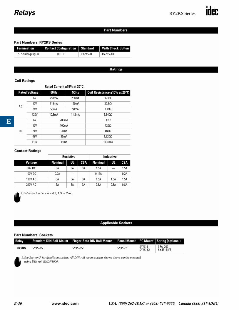
Termination Contact Configuration Standard With Check Button
S: Solder/plug-in DPDT RY2KS-U RY2KS-UC
Rated Current ±15% at 20°C
Rated Voltage 60Hz 50Hz Coil Resistance ±10% at 20°C
AC
6V 250mA 260mA 6.3Ω
12V 115mA 120mA 30.3Ω
24V 56mA 58mA 132Ω
120V 10.8mA 11.2mA 3,840Ω
DC
6V 200mA 30Ω
12V 100mA 120Ω
24V 50mA 480Ω
48V 25mA 1,920Ω
110V 11mA 10,000Ω
Resistive Inductive
Voltage Nominal UL CSA Nominal UL CSA
30V DC 3A 3A 3A 1.5A — 1.5A
100V DC 0.2A — — 0.12A — 0.2A
120V AC 3A 3A 3A 1.5A 1.5A 1.5A
240V AC 3A 3A 3A 0.8A 0.8A 0.8A
Relay Standard DIN Rail Mount Finger-Safe DIN Rail Mount Panel Mount PC Mount Spring (optional)
RY2KS SY4S-05 SY4S-05C SY4S-51 SY4S-61SY4S-62
SFA-202SY4S-51F3
Part Numbers
Ratings
2. Inductive load cos ø = 0.3, L/R = 7ms.
Applicable Sockets
1.See Section F for details on sockets. All DIN rail mount sockets shown above can be mounted using DIN rail BNDN1000.
Relays RY2KS Series
www.idec.com USA: (800) 262-IDEC or (408) 747-0550, Canada (888) 317-IDEC E-31
E
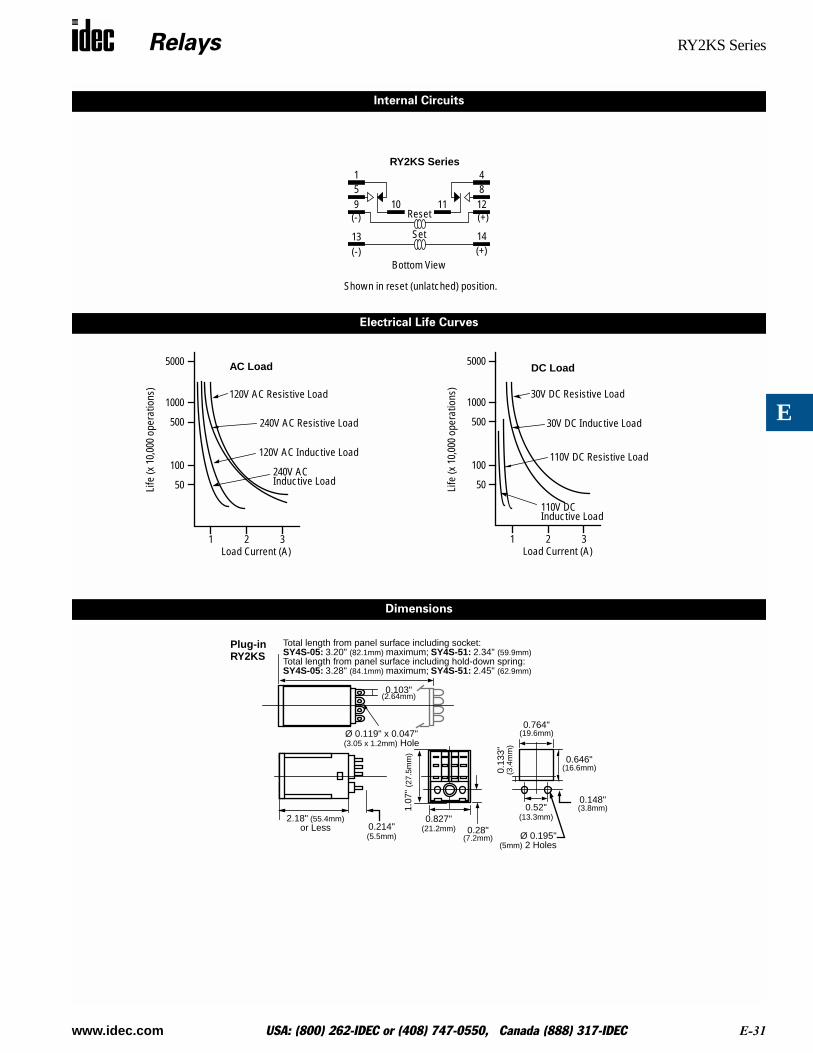
51
9
1413(-) (+)
10 1184
12Reset
Set
Bottom View
RY2KS Series
(+)(-)
Internal Circuits
Electrical Life Curves
5000
1000
500
100
50Life
(x 1
0,00
0 op
erat
ions
)
1 2 3Load Current (A)
AC Load
120V AC Resistive Load
240V AC Resistive Load
120V AC Inductive Load
240V ACInductive Load
5000
1000
500
100
50Life
(x 1
0,00
0 op
erat
ions
)
1 2 3Load Current (A)
DC Load
30V DC Resistive Load
30V DC Inductive Load
110V DC Resistive Load
110V DCInductive Load
Dimensions
Total length from panel surface including socket:SY4S-05: 3.20" (82.1mm) maximum; SY4S-51: 2.34" (59.9mm)Total length from panel surface including hold-down spring:SY4S-05: 3.28" (84.1mm) maximum; SY4S-51: 2.45" (62.9mm)
0.103"(2.64mm)
Ø 0.119" x 0.047"
2.18" (55.4mm)
1.07
" (2
7.5m
m)
0.827"or Less
0.764"
0.13
3"(3
.4m
m)
0.646"(16.6mm)
0.148"(3.8mm)0.52"
(13.3mm)
Ø 0.195"(5mm) 2 Holes
0.214"(5.5mm)
0.28"
Plug-inRY2KS
(3.05 x 1.2mm) Hole
(21.2mm)(7.2mm)
(19.6mm)
Shown in reset (unlatched) position.
Relays RY2L Series
E-32 www.idec.com USA: (800) 262-IDEC or (408) 747-0550, Canada (888) 317-IDEC
E
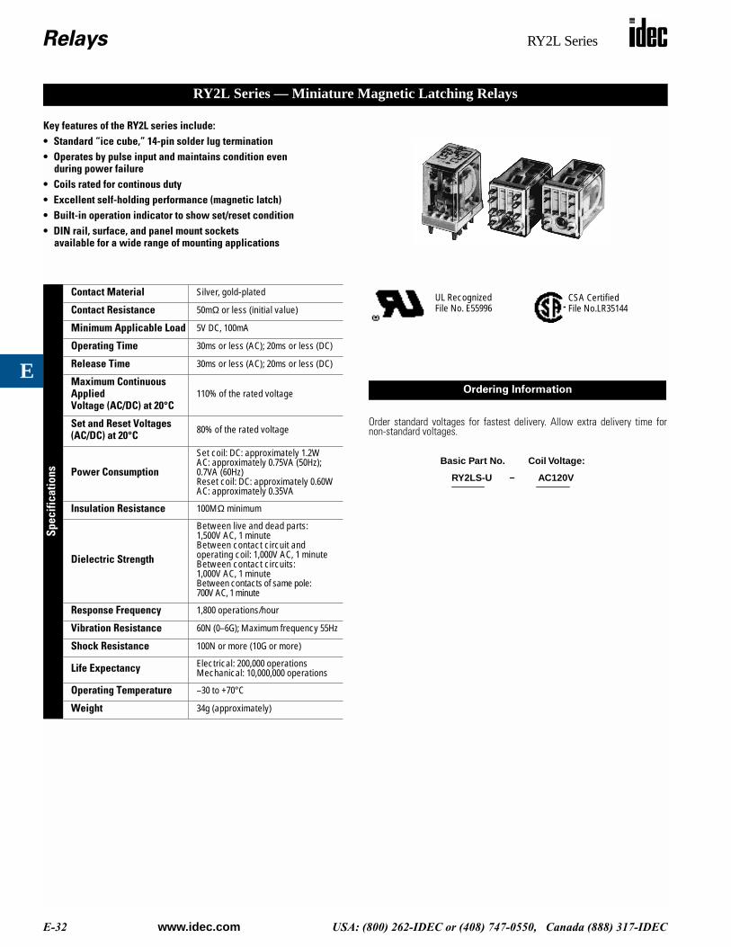
Key features of the RY2L series include:• Standard “ice cube,” 14-pin solder lug termination• Operates by pulse input and maintains condition even
during power failure• Coils rated for continous duty• Excellent self-holding performance (magnetic latch)• Built-in operation indicator to show set/reset condition• DIN rail, surface, and panel mount sockets
available for a wide range of mounting applications
Spec
ifica
tions
Contact Material Silver, gold-plated
Contact Resistance 50mΩ or less (initial value)
Minimum Applicable Load 5V DC, 100mA
Operating Time 30ms or less (AC); 20ms or less (DC)
Release Time 30ms or less (AC); 20ms or less (DC)
Maximum Continuous Applied Voltage (AC/DC) at 20°C
110% of the rated voltage
Set and Reset Voltages(AC/DC) at 20°C 80% of the rated voltage
Power Consumption
Set coil: DC: approximately 1.2WAC: approximately 0.75VA (50Hz); 0.7VA (60Hz)Reset coil: DC: approximately 0.60WAC: approximately 0.35VA
Insulation Resistance 100MΩ minimum
Dielectric Strength
Between live and dead parts:1,500V AC, 1 minuteBetween contact circuit and operating coil: 1,000V AC, 1 minuteBetween contact circuits: 1,000V AC, 1 minuteBetween contacts of same pole: 700V AC, 1 minute
Response Frequency 1,800 operations/hour
Vibration Resistance 60N (0–6G); Maximum frequency 55Hz
Shock Resistance 100N or more (10G or more)
Life Expectancy Electrical: 200,000 operationsMechanical: 10,000,000 operations
Operating Temperature –30 to +70°C
Weight 34g (approximately)
RY2L Series — Miniature Magnetic Latching Relays
Order standard voltages for fastest delivery. Allow extra delivery time fornon-standard voltages.
CSA CertifiedFile No.LR35144
UL RecognizedFile No. E55996
Ordering Information
RY2LS-U AC120V
Basic Part No. Coil Voltage:
–
Relays RY2L Series
www.idec.com USA: (800) 262-IDEC or (408) 747-0550, Canada (888) 317-IDEC E-33
E
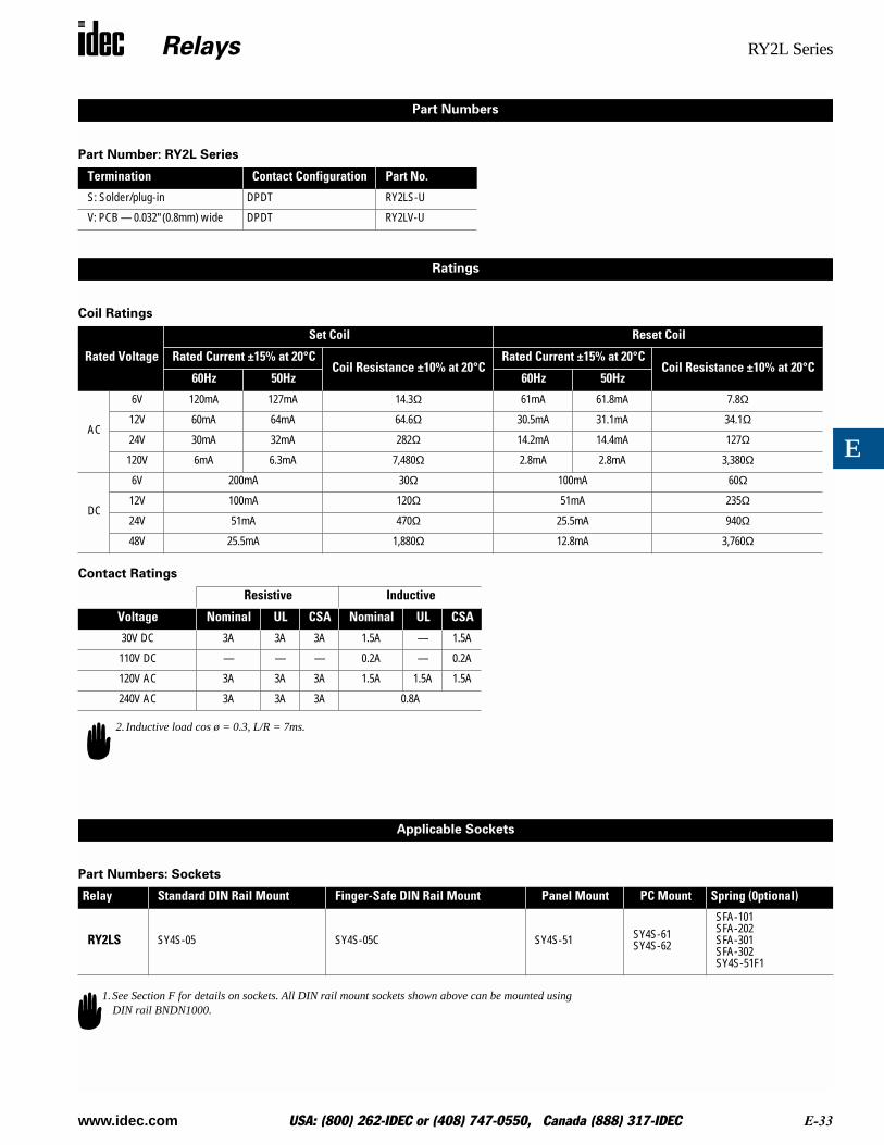
Part Number: RY2L Series
Coil Ratings
Contact Ratings
Part Numbers: Sockets
Termination Contact Configuration Part No.
S: Solder/plug-in DPDT RY2LS-U
V: PCB — 0.032" (0.8mm) wide DPDT RY2LV-U
Rated Voltage
Set Coil Reset Coil
Rated Current ±15% at 20°CCoil Resistance ±10% at 20°C
Rated Current ±15% at 20°CCoil Resistance ±10% at 20°C
60Hz 50Hz 60Hz 50Hz
AC
6V 120mA 127mA 14.3Ω 61mA 61.8mA 7.8Ω
12V 60mA 64mA 64.6Ω 30.5mA 31.1mA 34.1Ω
24V 30mA 32mA 282Ω 14.2mA 14.4mA 127Ω
120V 6mA 6.3mA 7,480Ω 2.8mA 2.8mA 3,380Ω
DC
6V 200mA 30Ω 100mA 60Ω
12V 100mA 120Ω 51mA 235Ω
24V 51mA 470Ω 25.5mA 940Ω
48V 25.5mA 1,880Ω 12.8mA 3,760Ω
Resistive Inductive
Voltage Nominal UL CSA Nominal UL CSA
30V DC 3A 3A 3A 1.5A — 1.5A
110V DC — — — 0.2A — 0.2A
120V AC 3A 3A 3A 1.5A 1.5A 1.5A
240V AC 3A 3A 3A 0.8A
Relay Standard DIN Rail Mount Finger-Safe DIN Rail Mount Panel Mount PC Mount Spring (0ptional)
RY2LS SY4S-05 SY4S-05C SY4S-51 SY4S-61SY4S-62
SFA-101SFA-202SFA-301SFA-302SY4S-51F1
Part Numbers
Ratings
2. Inductive load cos ø = 0.3, L/R = 7ms.
Applicable Sockets
1.See Section F for details on sockets. All DIN rail mount sockets shown above can be mounted using DIN rail BNDN1000.

Relays RY2L Series
E-34 www.idec.com USA: (800) 262-IDEC or (408) 747-0550, Canada (888) 317-IDEC
E
Internal Circuits
51
91413(-) (+)
10 1184
12
Reset
Set
Bottom View
(+)(-)
RY2L Series
Dimensions
Total length from panel surface including socket:SY4S-05: 2.42" (62.1mm) maximum; SY4S-51: 1.56" (40mm)Total length from panel surface including hold-down spring:SY4S-02: 2.50" (64.1mm) maximum; SY4S-51: 1.64" (42mm)
0.103"(2.64mm)
Ø 0.119" x 0.047"
1.40" (36mm)
0.019" (0.5mm)
1.07
" (2
7.5m
m)
0.827"or Less
0.764"
0.13
3"(3
.4m
m)
0.646"(16.6mm)
0.148"(3.8mm)0.52"
(13.3mm)
Ø 0.195"(5mm) 2 holes
0.214"(5.5mm)
0.28"
Plug-inRY2LS
1.40" (35.9mm) 0.137"
0.019"
1.07
" (2
7.5m
m)
0.827" (21.2mm)
0.031"
0.103"(2.64mm)
or Less
0.29
6"
Ø 0.039"
0.161"(4.13mm)
0.254"(6.5mm)
0.50"(12.8mm)
(3.5mm)
(1mm)
0.174"(4.46mm)0.
26"
(6.7
mm
)
0.154"(3.9mm)
0.26"(6.7mm)
PCB TerminalRY2LV
(3.05 x 1.2mm) Hole
(7.6
mm
)
3 Places
10 Holes
(0.5mm)
(0.8mm)
(19.6mm)
(21.2mm)
(7.2mm)
Shown in reset (unlatched) position.