Embed Size (px)
Citation preview

Section 31 31-1 January 2021
Section 31 - Treatment Plants A. Purpose – HRSD has historically had a broad range of experience with many different types
of treatment processes and equipment. This section documents best practices and criteria for the design and operation of HRSD treatment plants. This section is intended to be practical and prudent based on HRSD’s history and experience. This section is to be followed wherever practical and used in conjunction with the other documents listed herein for standardization and consistency. This section is not meant to be a definitive design manual for treatment plant projects. This section provides typical standards and/or guidelines for work associated with the construction, modification and/or rehabilitation of HRSD Treatment Plants and associated infrastructure. The information herein has been developed based previous experience which includes successes, failures and lessons learned.
1. HRSD owns and operates various wastewater treatment plants. These plants consist of
various unit processes, which are divided into Sewage Treatment and Solids Handling. a. Sewage Treatment: These processes typically consist of a preliminary process, a
primary process, and a secondary process, which purify the liquid wastewater entering the treatment plant before it is discharged to the receiving stream or recycled for water reuse.
b. Solids Handling: These processes typically consist of a thickening process, a dewatering process, and a solids disposal process, which dispose of or recycle the solid residuals produced from purifying the liquid wastewater.
2. HRSD treatment plants are designed and operated to:
a. Meet all regulatory requirements. b. Prevent offsite nuisance conditions. c. Be safe and reliable. d. Use proven equipment where applicable. e. Use automation and technology to minimize operating cost and maximize efficiency. f. Optimize life cycle cost.
3. Planning for new HRSD treatment plant facilities and projects is outlined in these
documents:
a. Solids Management Master Plan – Provides long-term planning to evaluate solids production, solids handling capabilities and deficiencies, and required new solids handling facilities for current and future conditions.
b. Capital Improvement Program (CIP) – Provides planning to initiate new projects.
4. Design and operating criteria for HRSD treatment plants are also outlined in the following documents:
a. Interceptor System Policies – Provides design and operating criteria for HRSD
interceptor systems and local collection systems.

Section 31 31-2 January 2021
b. HRSD Design and Construction Standards – Provides design and construction standards for new projects.
c. Commonwealth of Virginia Sewage Collection and Treatment (SCAT) Regulations – Provides design and operating criteria for sewerage systems and sewage treatment works in Virginia.
d. Hydraulic Institute Standards – Provides industry standards for the design, material, methods, performance, testing, etc. for hydraulic pumps and associated elements.
e. HRSD Standard Functional Descriptions.
5. The design and operation of HRSD treatment plants shall seek balance between design based on the way treatment plants are operated and operation based on the way treatment plants are designed.
6. Design of HRSD facilities should provide for occupancy, maintenance, and storage requirements such as conference rooms, restroom and locker room facilities, lunch room, storage area, maintenance work areas, office areas, etc.
7. Design for power failures and power failure restarts to ensure equipment fails and restarts in appropriate condition to protect personnel, facilities, and process.
B. Abbreviations - The following abbreviations shall be used on the construction documents for
all treatment plant related projects.
Abbreviation Definition ANOX Anoxic ANAE Anaerobic AER Aerobic AAA Anaerobic/Anoxic/Aerobic AAE Anaerobic/Anoxic Effluent AI Aeration Influent ALUM Alum Solution ANE Anaerobic Effluent APD Acid Phase Digester APDS Acid Phase Digester Solids API Acid Phase Influent APRS Acid Phase Recirculation Solids ARCY Anoxic Recycle ARE Aerated Effluent AS Air Supply (Low Pressure Process Air) ASR Aerated Supernatant Return AXE Anoxic Effluent BAS Backwash Air Supply BLWR Blower BWS Backwash Water Supply BWW Backwash Waste BWWR Backwash Waste Recycle

Section 31 31-3 January 2021
Abbreviation Definition CCK Centrifuge Biosolids Cake CCT Centrifuge Dewatering Centrate/ Chlorine Contact Tank CENT Centrifuge CNE Centrate Equalization CLS Chlorine Solution CSP Cake Storage Pad CST Caustic Storage Tank CTC Centrifuge Thickening Centrate CTI Centrate Treatment Influent CTP Centrate Treatment Process CTS Centrifuge Thickened Biosolids CTE Centrate Treatment System Effluent DA Polymer Dry Air DAF Dissolved Air Flotation Thickener DGAS Digester Gas DIG Digester DIST CH Distribution Chamber DPOLY Dry Polymer DPSD Drain Pump Station Discharge DS Digested Solids DSR Decant Supernatant Return DTD Decant Tank Drain FD Floor Drain FE Filtrate Effluent FERRIC Ferric Chloride/Sulfate FI Filtrate Influent FNE Final Effluent FOG Fats, Oils, and Grease FOP Fuel Oil Pump FOS Fuel Oil Supply FOR Fuel Oil Return FSB Dissolved Air Flotation Thickener Subnatant FTS Dissolved Air Flotation Thickener Solids GBFL Gravity Belt Filtrate GBT Gravity Belt Thickener GBTS Gravity Belt Thickened Solids GPD Gas Phase Digester GPDS Gas Phase Digested Solids GPE Gas Phase Effluent GPI Gas Phase Influent GPRS Gas Phase Recirculation Solids GRIT Grit GSP Gravity Thickener Overflow/Supernatant GTS Gravity Thickened Solids HDOIL Hydraulic Oil

Section 31 31-4 January 2021
Abbreviation Definition HW Headworks HWP Hot Water Pump HPW Hot Potable Water HWR Hot Water Return HWS Hot Water Supply IPS Intermediate Pump Station ISW Incinerator Scrubber Water LPROP Liquid Propane LPOLY Liquid Polymer METH Methanol MLSS Mixed Liquor Suspended Solids MURIATIC Muriatic Acid NAT GAS Natural Gas NPW Non-Potable Water NRCY Nitrified Recycle OA Odorous Air OCF Odor Control Fan OCS Odor Control Scrubber PCE Primary Clarifier Effluent PCI Primary Clarifier Influent PCS Primary Clarifier Solids PD Process Drain PDS Primary Digested Solids PDSP Primary Digester Supernatant POLYS Polymer Solution PTF Preliminary Treatment Facility PW Potable Water RAS Return Activated Solids RCP Recirculation Pump RD Roof Drain REAER Reaeration RWI Raw Wastewater Influent SA Service Air SAMP Sample SBD Scrubber Blowdown SBR Sequencing Batch Reactor SC Secondary Clarifier SCB Scum Concentrator Subnatant SCE Secondary Clarifier Effluent SCI Secondary Clarifier Influent ST Sidestream Treatment SCN Supplemental Carbon Neat/Screen SCS Supplemental Carbon Solution SCUM Scum SD Storm Drain

Section 31 31-5 January 2021
Abbreviation Definition SDS Secondary Digested Biosolids SDSP Secondary Digester Supernatant SEPT Septage BISULF Sodium Bisulfite CAUSTIC Sodium Hydroxide HYPO Sodium Hypochlorite SP Sump Pump SPD Sump Pump Discharge SPRAY Spray Water SR Supernatant Return SRC Scrubber Recirculation Cleaning SRD Scrubber Recirculation Discharge SRS Scrubber recirculation Suction SS Sanitary Sewer SSFM Sanitary Sewer Force Main STEAM Steam SW Seal Water TS Thickened Solids TSR Thickener Supernatant Return TWAS Thickened Waste Activated Solids V Vent WAS Waste Activated Solids
C. Sewage Treatment Design and Operation:
1. Regulations – The design and operation of sewage treatment facilities should be in
accordance with all provisions of the approved SCAT Regulations.
2. Design Life – The design life of sewage treatment facilities should be greater than or equal to the following: a. Structures: 50 years b. Piping and Conveyance: 50 years c. Mechanical Equipment: 20 years d. Electrical Power Equipment: 20 years e. Instrumentation And Control Equipment: 5 to 10 years
3. Flood Elevations – The flood elevations for sewage treatment unit processes should be based on the historical flood elevations listed below except on a case by case basis to meet existing or unusual conditions or where the discharge is to sensitive receiving waters: a. 25 Year Flood Elevation to remain fully operational. b. 100 Year Flood Elevation to protect structures housing critical operating equipment
from flooding.
Section 31 31-6 January 2021
4. Operating Elevation, Design Flow – Consult with the Hydraulic Analysis Review Team
(HART) report to determine design criteria if applicable or obtain hydraulic data from HRSD Hydraulic Analysis Managers.
5. Nutrient Removal
a. Provide consistent tank nomenclature at Biological Nutrient Removal (BNR) plants.
Engineering documents and drawings should use this nomenclature.
i. “1st Anoxic Zone” is correct. Do not use “Pre-anoxic zone”. ii. “2nd Anoxic Zone” is correct. Do not use “Post-anoxic zone”.
iii. Number multiple cells within an Anoxic or Aerobic zone according to the flow direction in the tank; for example: 2nd Anoxic Zone, Cell 1; 2nd Anoxic Zone, Cell 2; 2nd Anoxic Zone, Cell 3.
iv. For step feed process, use “1st Anoxic Zone”, “2nd Anoxic Zone”, “3rd Anoxic Zone”, etc and “1st Aerobic”, “2nd Aerobic”, “3rd Aerobic”, etc.
v. For Bardenpho processes, use “Aerobic Zone” and “Reaeration Zone”.
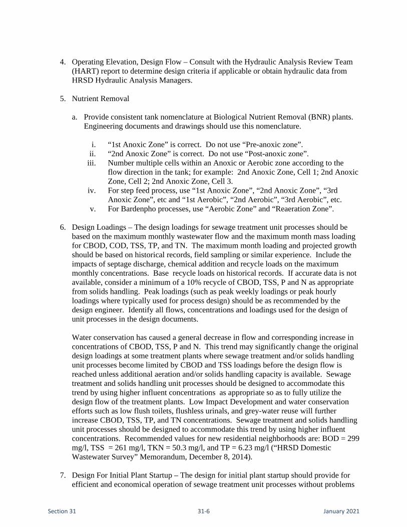
6. Design Loadings – The design loadings for sewage treatment unit processes should be based on the maximum monthly wastewater flow and the maximum month mass loading for CBOD, COD, TSS, TP, and TN. The maximum month loading and projected growth should be based on historical records, field sampling or similar experience. Include the impacts of septage discharge, chemical addition and recycle loads on the maximum monthly concentrations. Base recycle loads on historical records. If accurate data is not available, consider a minimum of a 10% recycle of CBOD, TSS, P and N as appropriate from solids handling. Peak loadings (such as peak weekly loadings or peak hourly loadings where typically used for process design) should be as recommended by the design engineer. Identify all flows, concentrations and loadings used for the design of unit processes in the design documents. Water conservation has caused a general decrease in flow and corresponding increase in concentrations of CBOD, TSS, P and N. This trend may significantly change the original design loadings at some treatment plants where sewage treatment and/or solids handling unit processes become limited by CBOD and TSS loadings before the design flow is reached unless additional aeration and/or solids handling capacity is available. Sewage treatment and solids handling unit processes should be designed to accommodate this trend by using higher influent concentrations as appropriate so as to fully utilize the design flow of the treatment plants. Low Impact Development and water conservation efforts such as low flush toilets, flushless urinals, and grey-water reuse will further increase CBOD, TSS, TP, and TN concentrations. Sewage treatment and solids handling unit processes should be designed to accommodate this trend by using higher influent concentrations. Recommended values for new residential neighborhoods are: BOD = 299 mg/l, TSS = 261 mg/l, TKN = 50.3 mg/l, and TP = 6.23 mg/l (“HRSD Domestic Wastewater Survey” Memorandum, December 8, 2014).
7. Design For Initial Plant Startup – The design for initial plant startup should provide for efficient and economical operation of sewage treatment unit processes without problems

Section 31 31-7 January 2021
caused by oversized tanks and equipment if low flows are expected during early years of operation. The design for initial plant startup may incorporate:
a. Sufficient turndown capability b. Additional smaller initial equipment to be operated only at lower flows. c. Multiple smaller initial equipment to be operated together at higher flows.
8. Outfalls And Outfall Diffusers – Consult with the Hydraulic Analysis Review Team (HART) report to determine design criteria if applicable or obtain hydraulic data from HRSD Hydraulic Analysis Managers..
9. Reliability And Redundancy – The reliability and redundancy of major sewage treatment
equipment should be the ability to take any one unit process train out of service at design flow as long as all unit process trains of all other unit processes remain in service. Verify that the design complies with SCAT Regulations.
10. Equipment Selection – The current, approved list of sole-source equipment can be found on Sharepoint site under Finance / Sole Source/ COMMISSION APPROVED SOLE SOURCE ITEMS . Users without Sharepoint access may request this document by contacting the Engineering Department.
11. Minimum Requirements:
Sewage
Treatment Unit Process
Min. No. of Units Installed
No. of Units Out of Service
Comments
Flow Measurement
1 0 Provide flow measurement with totalizer. FNE is preferred over RWI. Internal recycle streams are to be separate (after RWI measurement or prior to FNE measurement). Consider parshall flume, venturi, or magmeter. Employ only flow meter equipment that is accurate and non-ragging/self-cleaning.
Influent Pumping

Section 31 31-8 January 2021
Sewage Treatment Unit
Process
Min. No. of Units Installed
No. of Units Out of Service
Comments
Pumps Minimum 3 units (includes one spare) Firm capacity to be determined by HRSD Planning & Analysis of 2.5 times design flow Meet firm capacity with largest unit out of service
1 Provide for all pumps to be variable speed. The 1st pump runs continuously, the 2nd pump starts when 1st pump cannot handle all of the flow. Additional pumps run when 1st and 2nd pumps cannot handle flow or upon failure of 1st or 2nd pump.
Wet Wells/ Channels
As required As required Consider self-cleaning wet wells. Match size and controls to pumping requirements to prevent frequent start/stop of pumps. Consider means to remove wet wells and enclosed channels from service in the future for maintenance of concrete and coatings. Provide for personnel access into wet well. Provide protective lining or coating at linear trench style self-cleaning wet wells for RWI service.
Automatic Actuators
- - Provide automatic actuators on all critical control gates and valves. Consider remote DCS control and provide at a minimum position indication.
Isolation Gates - - Provide secondary means of closure at all gates. Stop logs or Stop Gates may be considered provided they: • meet the same AWWA leakage
rates specified for slide gates • are engineered and composed
of:

Section 31 31-9 January 2021
Sewage Treatment Unit
Process
Min. No. of Units Installed
No. of Units Out of Service
Comments
o FRP encapsulated A36 steel or 304 SST for the stop log / stop gate panel
o neoprene rubber for the seals
o SST for the slide frame and hardware with replaceable UHMW guide strips and neoprene guide seals.
• have logs that are a minimum of 3-1/2” thick with opposing bottom-mounted dual “J” seals
• have surface mounted slide channel frame guides permanently installed in channel walls with a flat bottom sealing surface (no sealing keyway/grove) for the stop logs to seal against,
• have a mechanical galvanized lifting beam assembly to place and retrieve the stop log or stop gates
• are mounted in areas accessible to a portable gantry for use with the lifting beam assembly. If not, a permanent gantry or jib must be installed and positioned to accommodate log/gate installation and extraction.

Section 31 31-10 January 2021
Sewage Treatment Unit
Process
Min. No. of Units Installed
No. of Units Out of Service
Comments
Bar Screens 2 minimum; Sized for 2.5 x annual average wastewater flow rate with largest unit out of service
1 Size to protect plant during severe storm flow conditions. Provide coarse screen bypass channel. Screenings are to be sluiced to a compactor. Dewater screenings using press or similar equipment. Discharge screenings into bulk storage containers. Minimum two containers, each sized for one screen. Manifold discharge screenings to multiple containers. Locate containers inside enclosed building with odor control.
Center Flow Band Screens and Drum Screens
2 minimum; Sized for 2.5 x annual average wastewater flow rate with largest unit out of service
1 Size to protect plant during severe flow conditions. Band screens are to have internal bypass overflows (bypass channel not required). Screenings are to be sluiced to a compactor. Discharge screenings into bulk storage containers. Minimum two containers, each sized for one screen. Manifold discharge screenings to multiple containers. Locate containers inside enclosed building with odor control.
Step Screens 2 minimum; Sized for 2.5 x annual average wastewater flow rate with largest unit out of service
1 Size to protect plant during severe flow conditions. Provide coarse screen bypass channel for emergency use. Screenings are to be sluiced to a compactor. Discharge screenings into bulk storage containers. Minimum two containers, each sized for one screen. Manifold discharge screenings to multiple containers. Locate containers inside enclosed building with odor control.

Section 31 31-11 January 2021
Sewage Treatment Unit
Process
Min. No. of Units Installed
No. of Units Out of Service
Comments
Grit Removal Tanks
2 minimum; Sized for 2.0 x annual average wastewater flow with largest unit out of service
1
Size to protect plant during severe storm flow conditions. Consider only detritors, stacked vortex (Head Cell), or structured vortex (Grit King). Avoid aerated grit, forced vortex, and velocity channels (grit channels). Consider collection system diurnal velocities for deposition of grit and storm slug loads.
Grit Pumps 2 per tank 1 Size each unit to handle total tank loading. Do not provide interconnection between tanks. Minimum grit pipe diameter is 6-inch. Minimum grit pump suction / discharge size is 4-inch / 4-inch. Provide flushing water on suction side of pumps.
Classifiers 2 per tank 1 Size each unit to handle total tank loading.
Hopper 1 0 Discharge all classifiers into 1 hopper. Locate hopper inside enclosed building with odor control.
Pre-Aeration - - Do not use. Primary Clarifiers
Tanks 3 sized for design loadings
1
Prefer circular units if space available due to less maintenance and better thickening. Consider separate fermenter for BNR if circular units used. For circular tanks, evaluate stainless steel rake and scum systems, FRP weirs/wells, SS center pier.

Section 31 31-12 January 2021
Sewage Treatment Unit
Process
Min. No. of Units Installed
No. of Units Out of Service
Comments
Solids Pumps 1 dedicated pump per clarifier with 1 spare pump per 2 or 3 clarifiers
1 Provide turndown capability or smaller pumps for low flow requirements at initial plant startup with provisions to replace smaller pumps as plant expands. Provide grinder or solids screen with bypass line ahead of each pump. Pumps with internal cutting blades can be considered if grinder installation is not practical due to space limitations.
Intermediate Pumping
Refer to Pump subheading in Influent Pumping.
Aeration Tanks
3 minimum; accommodate 2.5 times design flow with one tank out of service
1
Provide foam re-entrainment and/or foam removal.
Blowers 3 sized for design loadings with largest unit out of service
1 Provide turndown capability or 2 smaller blowers approximating 1 larger blower for low air requirements at initial plant startup with provisions to replace smaller blowers or install additional blowers as plant expands. Provide automatic start/stop and air control. Refer to HRSD Standard Functional Descriptions for control regimes. Locate blowers near aeration tanks to minimize air piping.
Air Piping - - Locate air piping above ground or in tunnels; do not bury.
Air Diffusers - - Fine bubble diffused air system.

Section 31 31-13 January 2021
Sewage Treatment Unit
Process
Min. No. of Units Installed
No. of Units Out of Service
Comments
Secondary Clarifiers
Tanks
3 minimum; accommodate 2.5 times design flow with one tank out of service
1
RAS Pumps 1 dedicated pump per clarifier with provision for adequate number of spare pumps
1 Provide variable speed pumps sized for total dedicated pump capacity of 1.0 x maximum monthly wastewater flow.
WAS Pumps 2 typically pulling off RAS discharge
1 Provide turndown capability or smaller pumps for low flow requirements at initial plant startup with provisions to replace smaller pumps as plant expands.
Chlorine Contact Tanks
2 sized for design flows
1 Provide 30 minutes detention time at maximum monthly wastewater flow (corresponding to SCAT terminology of average daily wastewater flow) or 20 minutes at 2.0 x maximum monthly wastewater flow (corresponding to SCAT terminology of maximum daily wastewater flow) whichever is greater with largest unit out of service. Provide scum removal system.
Effluent Pumping Pumps
3 sized for 2.5 x design waste-water flow with largest unit out of service
1
Provide variable speed pumps. Controls shall conform to HRSD Standard Functional Description.

Section 31 31-14 January 2021
Sewage Treatment Unit
Process
Min. No. of Units Installed
No. of Units Out of Service
Comments
Wet Well - - Match size and controls to pumping requirements to prevent frequent start/stop of pumps. Locate close to chlorine contact tanks. Provide scum removal system.
Non-Potable Pumps and Automatic Strainers
3 1 May need additional pumps for multiple purposes, wide flow range, or low flow requirements at initial plant startup. Locate suction before dechlorination. Refer to HRSD Standard Functional Descriptions for control. Ensure complete by-pass capabilities for strainer maintenance.
Scum Removal Wells and Holding Tanks
-
-
Provide for agitation to break up crusted scum and automatic pump out of scum without excessive water. Consider morning glory / tee valve to minimize water content of pumped scum.
Scum Transfer Pumps
2 per well or holding tank
1 Provide grinder ahead of each pump. Do not use air operated diaphragm pumps.
Scum Piping - - Minimum 4-inch diameter. Corrosion-resistant glass lined ductile iron, HDPE, or PVC. Long radius bends, cleanouts, NPW flushing connections.
Concentrator 2 1
Concentrated Scum Pumps
2 per concentrator
1 Do not use air operated diaphragm pumps.

Section 31 31-15 January 2021
Sewage Treatment Unit
Process
Min. No. of Units Installed
No. of Units Out of Service
Comments
Concentrated Scum Piping
- - Maximum 4-inch diameter. Corrosion-resistant glass lined ductile iron, PVC, or HDPE. Long radius bends, cleanouts, NPW flushing connections, and air connection at injection point to furnace.
Chemical Feed Systems
Pumps
1 dedicated pump per feed point with 1 spare pump connected to manifold
-
Provide turndown capability or range of pump sizes to accommodate low flow and high flow requirements. Flow meters to read accurately at all anticipated flow ranges.
Odor Control Enclosed Facilities and Covered Tanks
-
-
Consider on case by case basis.
Scrubbers 2 trains of 2 scrubbers each including standby train for sewage treatment
1 train Consider 1 large odor control station versus multiple smaller odor control stations on case by case basis. Provide additional trains for large air flows. Consider bioscrubbers and carbon scrubbers where applicable.
2 scrubbers including standby scrubber for solids handling where single stage scrubbing is appropriate or as above for sewage treatment where two stage scrubbing is required
1 scrubber Provide for chemical cleaning of scrubbers.

Section 31 31-16 January 2021
Sewage Treatment Unit
Process
Min. No. of Units Installed
No. of Units Out of Service
Comments
Emergency Power Generators
1 sized on case by case basis to power all sewage treatment operations at 2.5 x maximum monthly wastewater flow plus critical solids handling operations on a case by case basis
0
Satisfy Class I Reliability requirements. Provide emergency generator(s) rated to adequately power required plant loads. Provide sufficient fuel storage for a 7 consecutive day utility outage at full load.
UPS - - Provide backup power for sufficient time at control stations for critical computer, data collection and I&C functions.
D. Solids Handling Design and Operation:
1. The planning and selection of solids handling facilities, unit processes and final solids use or disposal should be in accordance with the Solids Management Plan on HRSD SharePoint site. The evaluation of new solids handling facilities should consider alternative and multiple methods and backup plans to provide for flexibility and contingencies in case of process failure or new regulatory requirements. The design and operation of solids handling facilities should be in accordance with all provisions of the approved SCAT Regulations. Solids handling design and operation should also comply with the requirements of the 40 CFR Part 503, MACT 129, and Title V regulations.
2. Design Life – The design life for various elements of solids handling facilities should be greater than or equal to the following:
a. Structures: 50 years b. Piping and Conveyance: 50 years c. Mechanical Equipment: 20 years d. Electrical Power Equipment: 20 years e. Instrumentation and Control Equipment: 5 to 10 years

Section 31 31-17 January 2021
3. Solids Capacity – The solids capacity for solids handling unit processes should be based on the following criteria:
a. Plant Solids Capacity – The plant solids capacity of the overall solids handling
facilities should be based on solids production at maximum monthly flow and load. b. Process Solids Capacity – The process solids capacity for individual solids handling
unit processes including recycle loadings and peak loadings (such as peak weekly loadings or peak hourly loadings) should be as recommended by the design enigneer.
c. Limiting Solids Capacity – The limiting solids capacity of the overall solids handling facilities should be based on the individual solids handling unit process having the lowest monthly solids capacity (i.e. the bottleneck).
Note: Observations on loadings and capacity of solids handling unit processes based on HRSD analysis and experience are as follows: • Peak daily loadings are buffered (absorbed) by peak weekly loadings. • Incinerator capacity is related as follows:
Peak Daily Capacity = Equipment Rated Max. Capacity Peak Weekly Capacity ~ Peak Daily Capacity due to buffering
capacity = Equipment Rated Max. Capacity
Max. Monthly Capacity = 85% x Peak Weekly Capacity = 85% x Equipment Rated Max. Capacity
Avg. Monthly Capacity = 85% x Max. Monthly Capacity = 85% x 85% x Peak Weekly Capacity = 72% x Peak Weekly Capacity = 72% x Equipment Rated Max. Capacity
4. Design Loadings – The design loadings for solids handling unit processes are to be as recommended by the design engineer. The design loadings should be based on historical records, field sampling, or similar experience. The design loadings should include the impacts of septage discharge, chemical addition, and solids from other plants.
5. Design For Initial Plant Startup – The design for initial plant startup should provide for efficient and economical operation of sewage treatment unit processes without problems caused by oversized tanks and equipment if low flows are expected during early years of operation. The design for initial plant startup may incorporate:
a. Sufficient turndown capability b. Additional smaller initial equipment to be operated only at lower flows. c. Multiple smaller initial equipment to be operated together at higher flows.
6. Intermittent Operation – The intermittent operation of solids handling unit processes should be evaluated carefully to determine the impacts on other sewage treatment and

Section 31 31-18 January 2021
solids handling unit processes and operations at both initial plant startup and design loadings. A plan for intermittent operations, if applicable, should be developed by HRSD and forwarded to the design enigneer early in the design process.
7. Impact On Sewage Treatment – The impact of solids handling unit processes on other sewage treatment unit processes and operations should be evaluated carefully at both initial plant startup and design loadings. Such impacts from solids handling may be detrimental to performance of sewage treatment unit processes or operating efficiency of facilities. The evaluation should consider factors such as: a. Initial and design loadings b. Size of equipment and turndown capability c. Intermittent operation and hours of operation d. Recycle load impact on unit processes e. Interdependent onsite and offsite unit processes and operations
8. Reliability And Redundancy – The reliability and redundancy of solids handling unit processes should be based on operating with the largest unit out of service. The reliability and redundancy of major solids handling equipment should be based on having a spare unit of the largest size. Verify that the design complies with the SCAT Regulations.
9. Equipment Selection – The current, approved list of sole-source equipment can be found on Sharepoint site under Finance / Sole Source/ COMMISSION APPROVED SOLE SOURCE ITEMS . Users without Sharepoint access may request this document by contacting the Engineering Department.
10. Minimum Requirements:
Solids Handling
Unit Process Min. No. of
Units Installed
No. of Units Out of Service
Comments
Holding Tanks
Need to evaluate mixing requirements. Consider Confined Space Entry Permit requirements when designing access for cleaning and inspection. Provide odor scrubbing of the Holding Tanks
Storage 1 minimum, 2 preferred
1
Day 1 minimum, 2 preferred
1
Blend
1 minimum, 2 preferred
1
Thickeners
Gravity 2 sized for design loadings
1

Section 31 31-19 January 2021
Solids Handling Unit Process
Min. No. of Units
Installed
No. of Units Out of Service
Comments
Flotation 2 sized for design loadings w/ largest unit out of service
1
Gravity Belt 2 sized for design loadings w/ largest unit out of service
1
Thickened Solids Pumps
1 dedicated pump per unit with one spare pump where applicable
1 Provide VFD/pump system turndown capability or smaller pumps for low flow requirements at initial plant startup with provisions to replace smaller pumps as plant expands.
Hopper 1 0 Provide useable hopper volume to match operational and process requirements. Provide hopper level monitoring to control the Thickened Solids Pumps.
Anaerobic Digesters
Primary 2 sized for design loadings w/ largest unit out of service to meet Class B requirements
1
Requires 6 months to clean and repair digester. Both primary and secondary digesters shall be dual-purpose.
Secondary 1 sized for design loadings
1 Consider alternate gas storage on a case by case basis. Both primary and secondary digesters shall be dual-purpose.
2 Stage

Section 31 31-20 January 2021
Solids Handling Unit Process
Min. No. of Units
Installed
No. of Units Out of Service
Comments
Acid Phase 2 sized for design loadings w/ one unit out of service
1 Avoid P-traps on drawoffs due to gas/liquid binding.
Gas Phase 2 sized for design loadings w/ one unit out of service
1
Pumps 1 dedicated pump per unit with one spare pump per every two units
1 Provide turndown capability or smaller pumps for low flow requirements at initial plant startup with provisions to replace smaller pumps as plant expands.
Heat Exchangers
- - Shell and tube. Do not install spiral heat exchangers.
Foam Control
- - Consider foam control measures
Dewatering
Belt Filter Press
2 sized for design loadings w/ one unit out of service
1
Centrifuge 2 sized for design loadings w/ one unit out of service
1 Provide 1 spare uninstalled rotating assembly or 1 additional installed centrifuge. Requires 6 months for outside repair of centrifuge.
Pumps 1 pump per unit 1 Provide turndown capability or smaller pumps for low flow requirements at initial plant startup with provisions to replace smaller pumps as plant expands. Provide grinder ahead of each pump.

Section 31 31-21 January 2021
Solids Handling Unit Process
Min. No. of Units
Installed
No. of Units Out of Service
Comments
Hopper 2 1 Design system to be flexible for discharge into any / all hoppers. Provide useable hopper volume to match operational and process requirements. Account for working volume lost to angle of repose of dewatered solids.
Biosolids Receiving Facility
Loading Hopper
2 sized for usable volume to hold a minimum of 60 yd3 each
1 Design system to be flexible for discharge into any / all hoppers.Provide usable hopper volume to match operational and process requirements at both the loading and receiving plants. Account for working volume lost to angle of repose of dewatered solids.
Receiving Hopper
2 sized for usable volume to hold a minimum of 60 yd3 each
1 Provide usable hopper volume to match operational and process requirements at both the loading and receiving plants. Provide for unloading from different types of trucks where possible. Account for working volume lost to angle of repose of dewatered solids.
Pumps 1 dedicated pump per unit with one spare pump
1 Provide pump range and turndown capability to match operational and process requirements at both the loading and receiving plants
Incinerators
Fluidized Bed
2 sized for design loadings w/ largest unit out of service
1 Provide for MACT 129 requirements.

Section 31 31-22 January 2021
Solids Handling Unit Process
Min. No. of Units
Installed
No. of Units Out of Service
Comments
Polymer Systems
Pumps 1 dedicated pump per unit with 1 spare pump
1 Provide VFD/pump system turndown capability or smaller pumps for low flow requirements at initial plant startup with provisions to replace smaller pumps as plant expands.
E. Access to Unit Processes and Equipment
1. Provide access into enclosed and partially enclosed tanks, channels, and other structures to perform required inspection and maintenance. Design access points to minimize the impact on confined space entry through the use of gates, removable handrail sections, hatches with built in fall protection, anchor points, etc. Provide ground level access for above ground tanks.
2. Provide permanent stairs, ladders, or other assemblies to access tanks, buildings,
structures, equipment, valves, components, etc. in accordance with OSHA regulations. Provide landings with handrail systems at the top, and intermediate (as required) elevations of access assemblies. For ladder systems, elevate the first rung approximately 12-inches from the top-of-landing. Do not use Fiberglass Reinforced Plastic (FRP).
3. Provide elevated walkways with handrails in accordance with OSHA requirements to
access multiple tanks and/or structures that are located in close proximity to each other. The minimum width of walkways shall be four (4) feet .
4. Provide isolation valves upstream of all devices and appurtenences to allow for
maintenance or removal. Provide isolation valves from other tanks that are commonly piped together. Provide manway access into the tank for maintenance and internal inspections.
5. Refer to Section 21 HRSD Safety Standards within this manual for additional
requirements.
F. Sampling
1. Sampling is required for process monitoring and control and regulatory reporting. Sampling must be representative and reliable.

Section 31 31-23 January 2021
2. Sampling hatches shall be provided at designated sampling locations. All sample points shall be provided with 120V outlet connections. Raw influent and final effluent sample points shall be provided with a flow signal.
3. Sampling points are to be planned, designed and designated for all process flows and
other samples routinely monitored. Sampling points are to provide representative samples under all operating conditions. In general, sampling points are to be:
a. Located to include or exclude recycle streams as appropriate. b. Well mixed to avoid solids separation. c. Representative when process units are taken out of service. d. Easily accessible for sampling or maintenance.
4. Provide automatic samplers. Provide connections and appurtenances for automatic
samplers. Provide for manual sampling in the event of failure of the automatic sampling equipment.
5. Automatic Samplers:
a. Provide “composite-only” or “sequential/composite” samplers designed for
outdoor/corrosive environments and manufactured with an exterior shell made of UV resistant fiberglass. Enclosures shall be refrigerated and heated to control temperatures inside the unit. Place samplers on housekeeping pads.
b. Provide for external inputs for flow pacing and local receptacles for power. c. Coordinate with HRSD Technical Services Division to provide a bracket and pole for
support of the sample tubing, where appropriate. d. Provide for training of the plant staff for this piece of equipment. The training is to be
included with the purchase price and/or construction contract. e. Do not locate samplers in a classified space.
G. Chemical Containment
1. Provide a negative slope (minimum 1/8 inch per foot) on all floors to a sump or drain. 2. Select valves, piping, supports, and sump pump materials to be resistant to chemicals
stored. 3. Generally, a sump and pump are preferred over a drain system. Sumps to be recessed to
completely drain tank floor. 4. No equipment inside containment area – limit to piping and appurtenances. All tank
instrument read-outs are to be located outside of the containment. All pump shutdown HOAs are to be located outside of the containment. If equipment must be located inside containment, locate above expected elevation of contained liquid.. All piping is to be located above expected elevation of contained liquid.

Section 31 31-24 January 2021
5. Size containment areas to meet local building code. At a minimum, provide storage volume of 110% of the largest tank.
6. Minimize the installation of electrical conduit and heat trace systems within containment
areas. 7. Provide for potable or non-potable water for cleaning of the containment areas. For hose
connections, provide male polyethylene camlock connections with caps. 8. Consider the following questions when designing a sump pump system:
a. Will the pump be located in the sump or elevated on rails? b. Will the pump be designed to handle the chemical or to be replaced after each use? c. Is suction lift a problem? d. What is the ultimate discharge point for the pump and where will a spilled chemical
be pumped? e. Will the pump handle rainwater? f. Can a NPW eductor system be used in-lieu of an actual pump system?
NOTE: Draining chemical containment systems shall be a manual operation to ensure
that chemicals are not accidentally discharged to the storm drain or plant drain system.
9. Provide suitable access into containment areas.
10. Avoid piping and conduit penetrations through containment walls and floors.
11. Locate feed pump suction piping within the containment area.
12. Conduct a hydrostatic test of the containment area to ensure that there are no leaks.
13. Provide appropriate waterstop material in all concrete joints.
14. Provide close inspection of concrete workmanship and coating systems prior to the
placement of tanks and other equipment.
15. Provide local high level alarm for containment sump that is also capable of being displayed on plant DCS.
H. Chemical Feed Systems
1. General
a. Fill Stations
i. Provide adequate venting in the design of the chemical storage tanks and fill
piping. Consider the impact of vent discharge points on equipment and

Section 31 31-25 January 2021
personnel. Chemical suppliers often use compressed air to deliver the chemical into the storage tanks and to remove the contents of the supply hoses into the storage tanks.
ii. Provide male end polyethylene quick disconnect at fill stations. A dry-break fitting is not required.
iii. Consider use of duplex strainers in parallel on fill line. iv. Review the diameter of the quick disconnect with the plant staff to limit the
possibility of contamination with other chemicals on the plant site. v. Provide containment to connections and fill stations and provide a drain to a
proper discharge point. vi. Provide suitable ground connection for truck unloading of flammable
chemicals. Interlock fill valve permissive with ground connection.
b. Storage Tanks
i. Review sizing criteria for the tank(s) with the plant staff. Carefully consider the number of days of storage, volume needed for dilution, the number of tanks to allow for inspection and maintenance and minimum delivery volumes. A suggested method for calculating the volume of chemical to be stored is:
(a) 15 day peak use at plant capacity, or (b) 30 day average use at plant capacity (whichever is greater). (c) For chemicals which degrade significantly with time, such as sodium
hypochlorite, use a 7 day peak/15 day average demand to calculate storage volumes.
ii. Consider if level indication is needed with the tank. Ultrasonic type level
indicator is preferred except for flammable applications such as methanol, for which radar is preferred. Ultrasonic level indicators should be located in the top/center portion of the tank using a flanged connection. If vertical space is not available above the tank for installation or maintenance of the level indicator, consider the use of a differential pressure cell at the base of the tank. Refer to Section 30 - Electrical and Instrumentation in this manual for further details regarding level indicators. Provide sight glasses only if a redundant system is needed. If a sight glass is required, provide valves at both the top and bottom.
iii. Set relative elevations of tank and pumps to allow drawoff of full tank volume.
iv. Provide storage tanks with ladders, safety cages, platforms with rails, etc. in accordance with OSHA requirements. Adjacent piping should not limit access to these ladders or critical isolation valves. Isolation valves must be connected directly to the tank. Consider consolidating piping adjacent to tanks to minimize access and maintenance problems. Proper vertical clearance is also important to access tank manways and maintain equipment located on top of these tanks.

Section 31 31-26 January 2021
v. Provide multiple manway openings for access and ventilation on tanks with volumes greater than 1,000 gallons. Consider placement of manway openings for ease of access.
vi. Provide sloped tank bottoms to allow tanks to be completely emptied using installed drains or pumps.
vii. Design storage tanks considering compatibility with chemicals stored and concentrations anticipated.
viii. Permanently attach each tank’s nameplate information including manufacturer, year of manufacture, working volume, empty volume, material of construction, diameter, and product designed to store.
c. Piping & Appurtenances
i. Manifold piping, tanks, and pumps and provide valves and check valves in
appropriate locations to allow maximum operational and maintenance flexibility for any tank/pump/process train combination.
ii. Bolt critical valves directly to tank to simplify locating leaks. iii. Provide an appropriate discharge point for pressure relief valves used for
chemical feed systems. Detail or describe the ultimate discharge point if it is not adjacent to the limits of the work for the project.
iv. Provide ventilation lines for calibration columns plumbed to appropriate ventilation discharge points.
v. Provide a permanent pressure gauge on the suction and discharge of each pump with gauge isolation valve.
vi. Provide flushing connections at appropriate locations in each chemical feed system. Provide a hose connection on the suction and discharge piping manifold for flushing the system.
vii. Design piping located under or adjacent to roadways for H-20 loading. viii. Overhead chemical piping should be avoided whenever possible.
d. Feed Pumps
i. Provide pumps with a calibration column (manufacturer recommended or
HRSD Standard). Provide pulsation dampener, elapsed-time meter, back pressure and relief valve as recommended by the Manufacturer.
e. Flow Metering – Provide a valved bypass or other method to allow for removal and
maintenance of meters without spilling large amounts of chemical or shutting down critical plant processes.
f. Operations/Maintenance/Accessibility
i. Locate eyewash and emergency shower stations adjacent to new chemical
feed systems in accordance with OSHA regulations. The location of these stations should is to be designed to facilitate access with existing facilities. Review the location of existing eye wash stations to determine if these station locations are satisfactory for the new work. See the Emergency Eyewash and Showers paragraph in this Section for further information.

Section 31 31-27 January 2021
ii. Elevate pumps or other equipment which require regular maintenance at least two feet above the floor or access platform to facilitate maintenance. This preference should not take precedence over the hydraulic requirements of the pump.
iii. Provide duplex unit strainers accessible for maintenance when strainers are required for chemical systems.
iv. Provide access to items of regular use or maintenance (i.e. pump wet ends, isolation valves, etc.) without the need to enter tank containment areas whenever possible. Access to these items should also be provided with as little interference and obstructions as possible.
g. Chemical Off-Gassing – Provide storage tanks with vents larger in diameter
(minimum 2 to 5 times) than the fill piping. Carefully consider vent orientation and discharge to limit impacts to worker safety and corrosivity to adjacent facilities. Consider the use of scrubber systems if the discharge of the vent will negatively impact the adjacent area.
h. Electrical Equipment
i. Refer to Section 30 - Electrical and Instrumentation in this manual for further
information regarding electrical equipment used for chemical feed systems.
2. Caustic (NaOH) Systems
a. General – Caustic is primarily used by HRSD as part of the odor control process. The product is normally delivered at 50% strength and immediately diluted to a strength of 25%.
b. Storage Tanks
i. Provide steel tanks due to the heat released during the dilution procedure.
Utilize a post-weld heat treatment procedure in tank manufacturing.
ii. Provide an automatic batch control system with a metered water source for dilution. Utilize non-potable water for dilution purposes. Provide strainer on the non-potable water source.
iii. Provide for continuous mixing of the storage tank. The pump should be a air operated diaphragm or centrifugal type. Pump to be compatible with heat generated during dilution. Heat tracing and insulation of the tank is not required since the chemical is diluted immediately upon delivery. Insulation and heat tracing of the non-potable water piping is required for outdoor applications.
c. Piping & Appurtenances
i. Provide Schedule 80 CPVC.. For buried locations use piping shall be double
contained, either fusion welded high-density polyethylene (HDPE) or PVC with nylon braided reinforced tubing inside a PVC jacket pipe.

Section 31 31-28 January 2021
ii. Minimize or eliminate threaded fittings and unions whenever possible. Use flanged connections at all fittings, valves and other appurtenances. Gasket, O-rings, and pulsation dampener material shall be EPDM.
iii. Provide metal ball valves for diameters of less than or equal to three inches and metal or fiberglass composite ball valves for diameters over three inches. Provide backpressure valves designed to consider the caustic feed pump discharge pressure range.
iv. Heat trace and insulate all outside pipework.
d. Feed Pumps
i. Provide a minimum of two feed pumps for this application. Pumps should be positive displacement.
e. Flow Metering - Provide magnetic (Mag) type flow meters with a valved bypass for
each feed point. Mag meters must be mounted so that they are measuring a full pipe and so that they do not trap gases.
3. Sodium Hypochlorite (NaOCl) Systems
a. General – Sodium hypochlorite is used in the chlorine contact tanks, in the odor control scrubbers, for filamentous control in the returned activated biosolids system, and in other locations throughout the plant. The product is normally delivered at a strength between 12 – 15%.
b. Storage Tanks
i. Storage tanks to be manufactured of fiberglass reinforced plastic (FRP).
Material selected to be compatible with field installation of bulkhead fittings. Design flexible connection with tank piping due to expansion / flexure at connection points.
ii. Locate storage tanks indoors or in a covered location outdoors. For indoor locations, consider carefully room ventilation to limit the corrosive fumes common from this chemical. Provide insulation for all tanks located outdoors.
iii. Provide a transfer pump for this application to move product from storage tank to storage tank. Design the system to protect the transfer pump from running dry or provide a pump that is capable of running dry without causing damage to the pump.
c. Piping & Appurtenances
i. Design piping to feed the product in neat (undiluted) form to the final application point to eliminate scaling when mixed with non-potable water. Piping shall be rigid PVC (Schedule 80) for exposed locations and PVC braided tubing for buried locations. The tubing shall be encased in a suitable PVC conduit to limit accidental damage, to provide containment and to allow

Section 31 31-29 January 2021
for removal of the tubing in case of a leak. Provide redundant feed for buried piping for both disinfection and odor control applications. Provide access manholes at buried piping junction points and bends. Design manhole to provide containment of the chemical. Use Weld-On 724 piping glue by IPS Corporation or approved equal. Every effort should be used to minimize fittings and joints. Minimize or eliminate threaded fittings and unions if possible.
ii. Isolation valves shall be of diaphragm type. iii. Evaluate manifold venting back to storage tank. iv. Locate pressure relief / venting back to storage tank
d. Feed Pumps
i. Provide a redundant pump for each application. Give careful consideration to
the range of flows to be handled with this system. The feed pump system must handle both nighttime low flows and peak high flow conditions. The pumps shall be positive displacement. Provide a variable frequency drive with each disinfection and odor control metering pump.
ii. Provide isolated vent systems back to the storage tanks, flush connections at each pump and calibration column vent piping.
iii. Avoid Viton seats on ball check valves used as part of the pump assembly. HRSD has found that EPDM or teflon coated EPDM is an acceptable elastomer for this application.
e. Flow Metering – Provide magnetic type flow meters with a valved bypass for each
disinfection and odor control feed point.
f. Operations/Maintenance/Accessibility
i. Consider the use of a submersible mixing unit at the disinfection application feed point.
ii. Locate all exposed piping in areas that allow easy access for repair and which will not negatively affect adjacent equipment if a leak or spill occurs.
iii. Due to the strong odors resulting from this chemical, scrubber system on all vents are required if storage tanks are located indoors. Leak/fume detection is required if storage tanks are located indoors. Consider room ventilation and the use of 2 speed fans to evacuate excess odors
4. Sodium Bisulfite (NaHSO3) Systems
a. General – Sodium bisulfite is used to dechlorinate the treated effluent prior to
discharge at each plant (except for Atlantic Plant). The product is normally delivered at a strength of 38%.
b. Storage Tanks - See Sodium Hypochlorite Systems in this Section for tank
requirements except for the following:

Section 31 31-30 January 2021
i. Locate tanks indoors in a controlled environment due to the likelihood of this chemical freezing.
ii. Provide tanks with insulation. iii. Provide a two inch diameter fill station quick disconnect. Consider use of a
lockable cover on the quick disconnect. iv. Provide tanks with a recirculation pump to keep the product well mixed and
limit crystallization at the air-liquid interface.
c. Piping & Appurtenances
i. Provide Nylon braided reinforcement tubing in PVC. Larger piping using NPW as carrying water is not preferred.
ii. Provide all piping with heat tracing and insulation. Consider providing heat panels in-lieu of heat tracing and insulation at the feed pumps.
d. Feed Pumps – See Sodium Hypochlorite Systems in this Section for pump
requirements except for Viton. Viton is an acceptable material for ball check valve o-rings.
e. Flow Metering - Provide magnetic type flow metering with a valved bypass for both
non-potable water and sodium bisulfite service.
f. Operations/Maintenance/Accessibility
i. Due to the strong odors resulting from this chemical: (a) Scrubber systems on all vents are required. (b) Leak/fume detection equipment is required. (c) Consider carefully room ventilation and the use of two speed fans to
evacuate excess odors.
ii. Due to concerns with chemical freezing (<55 degrees Fahrenheit): (a) HRSD will provide a large face thermometer in all sodium bisulfite areas. (b) Consider temperature control alarms in all sodium bisulfite areas.
5. Muriatic Acid (HCL) Systems - Important Note: This chemical is very dangerous and
very corrosive. Close attention needs to be paid to materials and the pump/pipe arrangement for safety. Corrosion of electrical components also needs considered.
a. General – Muriatic acid is used as a process chemical in some odor control systems,
to clean odor control scrubbers and for other maintenance purposes. The product is normally delivered at a strength between 25% – 30%.
b. Storage Tanks - Review the tank sizing criteria with plant staff. The tank volume
sizing should include both process and cleaning requirements. It may be more economical to provide multiple tanks at multiple locations.
i. Provide tanks manufactured of either FRP or HDPE. Design flexible
connection with tank piping due to expansion / flexure at connection points.

Section 31 31-31 January 2021
ii. Provide tank level measurement. iii. Provide a tank vent to an appropriate discharge point. One option for the
discharge location of this vent is the odor control scrubber system duct.
c. Piping & Appurtenances – PVC (Schedule 80) piping is acceptable. PVC braided tubing for buried locations. The tubing shall be encased in a suitable PVC conduit to limit accidental damage, to provide containment and to allow for removal of the tubing in case of a leak.
d. Feed Pumps – Provide redundant pumps only if the chemical is used as part of the
odor control process. Provide a flushing connection at each pump.
e. Flow Metering - Provide a magnetic type flow meter with a valved bypass only if the chemical is used as part of the odor control process.
f. Operations/Maintenance/Accessibility
i. Design based on a batch feed process if the chemical is used for cleaning
purposes only. ii. Minimize the use of metallic components within the tank containment area.
6. Ferric and Ferrous Chloride/Sulfate (FeCl3 , FeCl2 FeSO4) Systems
a. General
i. Ferric chloride (30-33% typical delivery concentration) solution is used to
remove phosphorus through precipitation at various locations in the treatment process.
ii. Provide for ferric / ferrous to be fed to the primary, secondary clarifiers and sidestream treatment.
iii. Dilution of this chemical is normally not required. The product is normally fed neat to the application point.
iv. Locate proposed ferric / ferrous feed points in areas where metallic gates and/or piping will not be negatively affected.
b. Storage Tanks
i. Provide FRP tanks due to the corrosive nature of this chemical. Locate tanks
outdoors and provide insulation only (no heat tracing) for temperature control. Provide a minimum of two tanks. Design flexible connection with tank piping due to expansion / flexure at connection points.
ii. Consider the need for continuous mixing of the storage tank. If a recirculation system is provided then a pumped system sized for 100% turnover each day should be used. The pump provided shall be a non-metallic type.
iii. Provide a level indicator for level monitoring. A sight glass on the tank is not required.
iv. Consider the use of a storage tank fill manifold with duplex basket strainer.

Section 31 31-32 January 2021
c. Piping & Appurtenances – Provide PVC piping and appurtenances. Valves shall be PVC true union ball type. Support systems for piping and appurtenances shall be non-metallic. For buried applications, use PVC braided tubing encased in PVC conduit to limit accidental damage, to provide containment, and to allow for replacement of the tubing in case of a leak. Install buried utility warning tape and tracer wire approximately 18 inches above all installed pipelines.
d. Feed Pumps
i. Provide units similar to the requirements for caustic systems.
e. Flow Metering – Provide magnetic type flow meters with valved bypass.
f. Operations/Maintenance/Accessibility – Provide proper ventilation of the corrosive
fumes if ferric / ferrous system is located indoors. All items within the tank containment areas and exhaust fans and any associated items shall be non-metallic. All existing metallic equipment in areas where ferric / ferrous will be located must be replaced or protected from corrosive fumes.
7. Aqua-Ammonia (NH4OH) Systems
a. General – Aqua-Ammonia (less than 20% by weight) is used as a nutrient source to
enhance biological growth or is used to control chlorine demand during periods of partial nitrification. This chemical has a high pH, which results in operational problems similar to those found with caustic. The product is normally fed neat to the application point.
b. Storage Tanks - Provide steel or HDPE tanks. The tanks are normally under a small
amount of internal pressure, which requires special attention to venting and gas relief systems. Special tank linings are not required. Containment of the tanks is required and an outdoor location for the tanks is acceptable. Provide tank level measurement. A sight glass is not required.
c. Piping & Appurtenances - Provide steel piping and appurtenances. The use of
threaded fittings is acceptable. Valves shall be ball type, made of steel and rebuildable. For buried applications, use PVC braided tubing encased in PVC conduit to limit accidental damage, to provide containment, and to allow for replacement of the tubing in case of a leak. Install buried utility warning tape approximately 18 inches above all installed pipelines.
d. Feed Pumps - Provide units similar to the requirements for caustic systems. Pumps
are normally operated at a constant feed rate.
e. Flow Metering - As required.
8. Polymer Systems

Section 31 31-33 January 2021
a. General - Polymer systems are used by HRSD for many process applications. Polymers are commonly used to increase solids concentration at thickeners, centrifuges, and for secondary clarification. Many different types of polymers are used by HRSD. Both dry and liquid systems are used at HRSD. Dry feed systems should be located in an indoor and/or controlled environment. A typical liquid polymer system is shown in Figure 31-1.
Figure 31-1: Liquid Feed Polymer System Configuration
b. Storage Tank
i. Size storage tank for the larger of a 15-day peak use or a 30-day average use.
The product is stored neat. Size the mix and feed tanks according to dosage requirements and acceptable age of mix.
ii. Provide HDPE or FRP tanks with a conical bottom if possible. Provide side manway access for cleaning. Locate tanks indoors. Heat tracing and insulation are not required if the tanks are placed in an indoor and temperature-controlled environment. Design flexible connection with tank piping due to expansion / flexure at connection points.
iii. Provide a level indicator for level monitoring. A sight glass on the tank is not required. For automated sequence to control, refer to the HRSD Standard Functional Descriptions.
iv. Provide a mechanical mixer inside the mix tank.
c. Piping & Appurtenances
i. Provide PVC piping and appurtenances. Some polymer products tend to cause interior chemical build-up on the piping system. Provide appropriate flanged connections and unions to allow for removal and replacement. For small diameter piping (< 2 inches) provide PVC ball valves and for large diameter piping (>2 inches) provide PVC plug or ball valves.
d. Storage, Mix and Feed Pumps - Provide rotary or gear type storage pumps for liquid feed applications and progressive cavity type mix/feed pumps.
e. Flow Metering - Provide a magnetic type flow meter and a valved bypass on the
discharge of the feed pump combination.

Section 31 31-34 January 2021
f. Operations/Maintenance/Accessibility – Consider carefully room ventilation. Direct
tank vents to a suitable outdoor location.
9. Methanol a. Refer to HRSD Safety Department’s Safe Work Practice and Methanol Response
Procedures Documents for this information.
I. Drain Systems
1. Consider plant drain system hydraulic capacity. A hydraulic grade line should be plotted with each new plant drain. Surcharging of gravity systems should be controlled. Design system to convey contents of the largest tank in less than 12-hours.
2. Gravity drain systems are preferred over pumped systems for all processes except
primary and BNR unit process tanks. Provide valves for isolation and throttling of each tank or process. Provide regular access points (manholes) in gravity systems and cleanouts in pumped systems. Provide ability to pump out primary and BNR unit process tanks and return to in-service unit process/tank.
3. Grit, solids handling and polymer process areas require special plant drain considerations
due to the likelihood of plugging. Limit fittings, provide flushing connections and cleanouts, provide adequate diameter/slope of gravity drain system. Use long radius fittings.
4. Provide trench drains for pump galleries and evaluate trench drains for containment
areas. Grating to be easily removable and corrosion resistant.
5. Provide flushing and cleaning locations with plant drain systems. If multiple processes are connected to the plant drain a method of isolation is needed to allow for effective cleaning operations.
6. Drain systems shall be tested as described in the Pipeline portion of this Section.
7. All concrete embedded drain inlets must be poured with a slope to the drain intlets.
8. Provide drain located under each emergency eyewash and shower.
9. All process tank drains are to be sump, trench, or negative slope floor drains.
10. All process buildings are to have either trench drains to sump or at minimum one floor
drain for every 500 square feet of floor area. Floor drains are to be within three feet of process equipment.
11. Plant drains shall return upstream of influent screens.

Section 31 31-35 January 2021
J. Emergency Eyewash and Showers
1. Refer to Section 22 - HRSD Safety Programs for specific requirements.
K. Equipment Numbering Sequences
1. Equipment designations shall correspond to the existing Operations Department equipment identification number (EID) system and/or asset ID and plant unit process designations. All design drawings, specifications and Operations Manuals shall incorporate the plant unit process designation. The EID numbers shall be shown on the Record Drawings. The following alpha-numeric functional coding system is used to determine the EID: Plant Abbreviation/ST or SH/ Unit process – System – Subsystem – Component
a. Plant Abbreviation – Letter designation for each plant as follows:
i. Army Base – AB
ii. Atlantic – AT iii. Boat Harbor – BH iv. Central Middlesex - CM v. Chesapeake-Elizabeth – CE
vi. County Treatment Plant - CSY vii. James River – JR viii. King William - KW ix. Middle Peninsula – MP x. Nansemond – NP
xi. Town Plant - TSY xii. Urbana - U
xiii. Virginia Initiative Plant – VIP xiv. West Point - WP xv. Williamsburg – WB
xvi. York River – YR
b. ST or SH – Designates sewage treatment (ST) or solids handling (SH)
c. Unit Process – Letter designation as follows:
Code Unit Process A Administrative Facilities B Plant Utilities C Flow Storage/Equalization D Preliminary Treatment E Primary Treatment F Intermediate Treatment G Secondary Treatment

Section 31 31-36 January 2021
Code Unit Process H Sidestream Treatment I Tertiary Treatment J Disinfection K Effluent Pumping/Water Reclamation L Scum Disposal M Biosolids Thickening N Biosolids Anaerobic Digestion O Biosolids Heat Treatment P Biosolids Storage Q Biosolids Dewatering R Biosolids Incineration S Biosolids Composting T Biosolids Land Application U Odor Control
d. The System, Subsystem, and Component designations are assigned by the Maintenance Planner.
2. New equipment shall be designated using a priority sequence based on original plant’s existing numbering sequence. The FIRM shall review the sequence with the plant staff early in the design stage of the project.
L. Equipment Spare Parts
1. It is HRSD’s goal to minimize the inventory of unnecessary spare parts. Review the
plant’s needs for spare parts and recommended special equipment/tools with HRSD prior to including these components in the contract documents.
M. Miscellaneous Pump Items
1. Seal Water Piping
a. Use strained NPW or potable water for this application. Potable water should only be used as a back up seal water source should the NPW pumping system fail.
b. Provide manual bypass.
2. Sump Pumps
a. Sump pumps shall be designed to pass the product/chemicals in the area of the sump.
If the materials of construction necessary to safely pass the product/chemical under

Section 31 31-37 January 2021
consideration make the pump cost impractical, consider a lower cost, replaceable sump pump or manual NPW eductor system.
3. Shaft Guards – Manufacturer shall provide shaft guards to comply with OSHA requirements. Refer to 29 CFR 1910 Subpart O Machinery and Machine Guarding.
N. Noise Abatement for installed stationary equipment
1. Refer to Section 22 - HRSD Safety Programs section in this manual. 2. Consider sound attenuation in spaces that house equipment such as blowers, centrifuges,
odor control fans, incinerator fans and generators. 3. Minimize location of equipment and control devices in areas with significant noise levels. 4. Design equipment installed in exterior locations such that no offsite noise nuisance will
result.
O. Non-Potable Water Systems
1. Non-Potable Water (NPW) systems are used for certain plant treatment processes, cleaning and for flushing systems on some equipment seals. The NPW system should be designed to provide needed pressures at all locations of the plant while meeting regular water demands. A looped piping system that is isolated at each process should be provided.
2. Provide automatic cleaning strainers on the discharge of pumping systems.
3. Provide strainers at each major plant process or critical delivery point. 4. Consider how the NPW pumping system could be expanded in the future. Provide
redundant NPW pump and/or an emergency pump connection. 5. NPW piping shall be ductile iron, PVC or HDPE. 6. Provide NPW hydrants at each process location. NPW hydrants shall be located to limit
hose lengths to approximately 100 feet. Consider a quick disconnect, valve and drain in-lieu of a hydrant at process tank locations. Provide NPW hydrants with a self draining feature to limit freeze problems.
7. Exposed NPW systems to be painted and marked in accordance with the Miscellaneous,
Painting and Coatings section of this document. 8. Provide a stainless steel hose reel and washdown station at each plant process that
requires regular cleaning.

Section 31 31-38 January 2021
P. Odor Control and Room Ventilation
1. General
a. The following text lists HRSD’s current standards for the design of odor control facilities with respect to H2S. A different design approach will be required when there is a significant odor concern other than H2S. This standard addresses chemical packed towers. Consider combination bio-filter-chemical packed tower systems when applicable.
b. Design odor control facilities to to eliminate off-site nuisance odors. Odor control
facilities typically include enclosing the odorous work areas and covering odorous process areas, ducting the odorous gases to scrubbers, and scrubbing the odorous gases in a two stage packed tower scrubber system. With respect to dual stage chemical packed tower scrubbers:
i. Limit the first stage scrubber maximum influent H2S concentration to 75 ppm.
ii. Initially reducing the H2S concentration to less than 5 ppm in the first stage scrubber using only caustic to maintain a scrubber recirculation water flow pH range of 10 to 12.
iii. Achieving a first stage scrubber effluent H2S concentration of 1 to 5 ppm with a maximum effluent H2S concentration of 5 ppm.
iv. Obtaining the remaining H2S removal in the second stage scrubber using 6.12 gallons of hypochlorite per 1,000 cfm and sufficient caustic to maintain an optimum pH of 9.5 or greater.
NOTE: Alternative oxidant chemicals may be evaluated and utilized.
Alternative chemical feed control strategy such as ORP, or continuous H2S or chlorine gas monitors may be used. Achieving a second stage scrubber maximum effluent H2S concentration of 0.1 ppm.
2. Air Flow
a. Provide for sufficient air flow from enclosed work areas and covered process areas to provide adequate ventilation and odor control as appropriate. Entrance doors should be labeled with the design air changes per hour.
NOTE: Air flow for work areas occupied by personnel should be based on
ventilation requirements as appropriate. Air flow for ventilation should not be routed through odor control facilities wherever practical. Air flow for odor control in some situations can be substantially reduced by pressurizing work areas otherwise requiring only ventilation and drawing off only a portion of the ventilation air flow through the unit process openings for odor control. Air flow for odor control in other situations can be substantially

Section 31 31-39 January 2021
reduced in a work area by using covers or hoods on process equipment. The minimum air change requirement indicated below shall be maintained.
b. Provide air flow based on the more stringent of the NFPA 820 requirements, other
applicable codes, or the following design criteria:
i. Air Changes - Provide for the minimum number of air changes as follows:
Type of Area Air Changes Per Hour
Enclosed work area directly exposed to wastewater or solids with normal access by personnel Examples Bar Screen Room Grit Classifier Room Grit or Scum Dumpster Room Solids or Scum Thickener Room (uncovered) Solids Handling Filter Room Solids Conveyor or Hopper Room Truck Drive Through Room
12 x per hour
Enclosed work area not directly exposed to wastewater or solids with normal access by personnel Examples Solids Handling Centrifuge Room
6 x per hour
Enclosed access, equipment or storage area not directly exposed to wastewater or solids with normal access by personnel Examples Electrical Rooms Stairwells
1.5 x per hour
Covered process area with extreme turbulence or H2S levels without normal access by personnel Examples Screw Pumps Grit Tanks Pre-aeration Tanks
12 x per hour
Covered process area directly exposed to relatively turbulent wastewater or solids without normal access by personnel Examples Splitter Boxes Solids Handling Tanks (based on empty)
6 x per hour

Section 31 31-40 January 2021
Type of Area Air Changes Per Hour
Covered process area directly exposed to relatively quiescent wastewater or solids without normal access by personnel Examples Non-Aerated Channels Primary Clarifiers (including weirs) Anaerobic/Anoxic Tanks
4 x per hour
Covered process area receiving process air without normal access by personnel Examples Aerated Channels Aeration Tanks
Max Process Air + 10%
ii. Face Velocity - Provide for a minimum face velocity of 100 FPM for any
indoor unit process opening. Provide for higher face velocities for outdoor unit process openings to counteract wind affects as appropriate.
iii. Sulfide Levels - Provide for a maximum sulfide concentration of 75 ppm at any point in the scrubber ductwork or scrubber influent so as to:
(a) Prevent backdraft of toxic levels into enclosed work areas, and (b) Ensure destruction of H2S in scrubber based on past operating
experience.
3. Public Acceptance, Nuisance Prevention and Odor Control – Public acceptance, nuisance prevention and odor control for treatment plants must be achieved for HRSD to provide quality service. Adverse impacts to nearby neighbors and communities from treatment plant facilities must be prevented, eliminated or minimized to the extent practical.
a. Public acceptance is critical for HRSD to build new treatment plant facilities to serve
the public. Public acceptance should be paramount when siting, designing and operating facilities, and these activities should be coordinated with the public information program to promote public acceptance. Nuisance prevention is required for treatment plants to be good neighbors. HRSD’s goal is to prevent offsite nuisances. Treatment plant facilities should be planned, designed and operated to mitigate offsite nuisances from odor, noise, light, traffic or other causes to the extent practical. Buffer areas should be in accordance with all provisions of the approved SCAT Regulations but in all cases should be at least 300 feet from any potentially nuisance process unit or activity to the property line for new treatment plants. The planning and design of facilities should also account for the inevitable encroachment of new residential, commercial and industrial neighbors on any nearby developable land.
4. Scrubber Equipment

Section 31 31-41 January 2021
a. Provide for a scrubber train consisting of two packed tower scrubbers connected in series per the following:
Packing detention time 1.3 – 1.6 seconds Packing depth 10 feet Packing type As appropriate Packing support Grating or gas injection plate Recirculation liquid to air ratio
15 – 20 gpm/1,000 cfm
Liquid distribution Single nozzle if less than 9 foot diameter, or a weir distribution system or multiple nozzle system with nine or more nozzles if greater than nine foot diameter.
Blowdown rate To be provided Mist eliminator Use mesh or media type
b. Provide for one or more individual scrubber trains connected and isolated in parallel
to accommodate the required size as appropriate.
c. Provide for one additional fully equipped standby scrubber train including induced draft fan connected and isolated in parallel with the other scrubber train(s).
d. Provide for each scrubber train a discharge stack designed to discharge at sufficient
height to disperse the emissions and eliminate offsite odors. Consider adding a directional stack piece on the stack discharge to direct air flow and air flow noise away from populated areas.
5. Chemical Feed
a. Provide for all scrubbers to be fed with caustic and sodium hypochlorite.
b. Provide for chemical feed rates per the following:
i. A minimum caustic feed to first stage scrubber of 3 pounds NaOH per pound of H2S to obtain a maximum effluent H2S concentration of 5 ppm.
ii. Sodium hypochlorite feed to the first stage scrubber (as an alternative sodium hypochlorite feed point in lieu of the second stage scrubber) of 2.1 gallons NaOCl per pound of H2S removed to obtain a maximum effluent H2S concentration of 5 ppm.
iii. Sodium hypochlorite feed to the second stage scrubber of 6.12 gallons of NaOCl/1,000 cfm and sufficient caustic to maintain a pH of 9.5 in the scrubber recirculation water flow or greater at a maximum influent H2S concentration of 5 ppm.

Section 31 31-42 January 2021
c. Provide for new caustic feed and storage facilities located separately or at the existing caustic feed facilities utilizing the available caustic storage facilities to the extent possible. Size the caustic storage tanks for a minimum of 15-days peak use or 30-days average use.
d. Evaluate the use of existing hypochlorite storage facilities to the extent possible. Size
sodium hypochlorite for a minimum 15-days storage at the average design feed rate.
e. Provide for at least one caustic feed pump for each operating scrubber with one standby caustic feed pump for the overall scrubber system.
f. Provide for at least one sodium hypochlorite pump for each operating two stage
scrubber system and one standby hypochlorite pump for the overall scrubber system.
g. Provide for automatic pH control of caustic feed for each scrubber using pH monitoring of the scrubber overflow. Also provide for automatic control of caustic feed to the first stage scrubber using continuous H2S monitors.
h. Provide for automatic control of sodium hypochlorite feed to each second stage
scrubber for H2S removal using ORP or continuous sulfide monitors.
i. Provide for adding chemicals to the suction or discharge side of the recirculation pump and/or to the scrubber sump if baffled to prevent short circuiting. Ensure chemicals are added downstream from the pH meter where feasible.
j. Provide for separate metering of caustic solution, sodium hypochlorite solution and
makeup water flows to each scrubber.
k. Provide muratic acid storage, pumping and containment for scrubber cleaning. Provide for manual control of acid feed.
i. If acid is fed to the first stage scrubber to decrease pH, then acid storage and
containment should be sized appropriately. Automatic acid feed based on pH should be provided.
6. Coatings - Provide for coating protection for covered process areas to prevent corrosion
due to H2S attack per the following and refer to the Coatings Manual.
a. Provide coatings on all exposed interior surfaces of covered process areas and extend coatings to one foot below the low water surface or to an appropriate termination point.
b. Consider life cycle cost in the selection of coatings.
c. For areas which can not be isolated and accessed for coatings maintenance using
existing plant valving (i.e. splitter boxes, flow distribution chambers/channels, etc.) consider the cost of over pumping in determining life cycle costs. Stronger consideration will be given to anticipated life of the coatings in these areas.

Section 31 31-43 January 2021
7. Duct Work
a. All duct shall be manufactured of fiberglass reinforced plastic (FRP). All FRP shall
have UV protection. Ductwork in most cases should be elevated above ground. Consider access and maintenance of adjacent equipment when locating ductwork.
b. Odorous air is almost always very humid. Provide a drain system at low points in
ductwork. Extend drain piping to existing drains or tanks. Drains must have a P-trap sufficient to overcome system vacuum.
8. Room Ventilation (As related to Odor Control)
a. See Air Flow at the beginning of this Section for air flow requirements.
b. Review with plant staff the use of timers, manual overrides and switches for the
proposed ventilation system in each area.
c. Provide the maximum distance possible in each building space between intake and exhaust locations to limit short-circuiting of air flow.
d. Utilize non-corrosive hardware for all exhaust fans and vent assemblies.
e. Design screened louvers to be accessible for maintenance and to limit rainwater from
entering the building space.
Q. Pipe Insulation and Heat Tracing
1. Provide a fiberglass, PVC jacketed insulation system.
2. Provide indicator (on/off) lights on all heat tracing systems. 3. Provide for piping insulation jacket to be color coded and/or stenciled in accordance with
HRSD’s Piping Identification and Color Code included in the “Miscellaneous” section of this manual.
4. Provide junction boxes/plugs on heat tracing systems to allow for removal of fittings,
valves, etc. 5. For new construction, provide power source with appropriate equipment. For retrofits
and improvements, indicate a location for the power feed to the proposed heat tracing system and verify that the existing power panel is suited for this application.
6. Refer to Section 32 - Electrical and Instrumentation in this manual for further information
regarding electrical equipment and requirements.

Section 31 31-44 January 2021
R. Primary and Secondary Clarifiers
1. Provide circular clarifiers with center feed, peripheral weir layout.. 2. The following system components should also be included in new or modified secondary
clarifiers:
a. Provide design which assures a watertight gearbox.
b. Provide a biosolids withdrawal system that is compatible with flow proportion RAS flow and does not require manual adjustment when flow volume or concentration changes. A suction plenum or Tow-Bro type biosolids collection system is preferred. Organ pipe drawoff systems are not acceptable.
c. All components shall be stainless steel.
d. Provide a modular drive system that can be repaired or replaced without dismantling
the clarifier structure.
e. Provide fiberglass clarifier weir covers designed to allow cleaning of weir and launder channels, or provide weir covers to deter algae growth.
f. Provide a gravity drain system if possible. Consider a method to fully drain clarifier
to allow for inspection and cleaning. Refer to drain system section [insert section number] for additional information.
g. Provide adequate NPW system to meet cleaning and tank filling needs.
h. Provide positive control of RAS flow from each individual clarifier.
i. Provide full diameter scum well and pump. Scum pump must not be hard piped to allow for easy removal during maintenance.
S. Process Air Piping
1. Process air piping shall be either stainless steel or welded carbon steel. Process air piping shall be placed in the following locations:
a. Above grade b. Direct bury with a proper coating and/or cathodic protection system. Avoid buried
pipe whenever possible.
2. Thermal expansion and contraction must be carefully considered with this piping system. Methods for support and/or restraint must be coordinated with the possibility of thermal expansion and contraction.

Section 31 31-45 January 2021
T. Process Flow Splitting
1. Perform a hydraulic analysis to verify that adequate flow splitting occurs for the following conditions:
a. Daily Average Flows – existing and at the rated plant capacity. b. Diurnal Flows – average daily minimum and maximum at existing flow conditions. c. Unit out of Service – when multiple units are included in the design, consider the
impacts of the largest unit out of service.
i. Provide for flow balancing between multiple units using low velocity channels where feasible. If channels are not possible, provide valves designed for throttling and/or adjustable gates/weirs.
ii. Buried valves designed for throttling shall be located in a vault and sized to allow for access and future removal of the equipment.
iii. Review with HRSD the anticipated frequency of flow balancing and the value/cost of providing remote monitoring and control.
U. Scum Handling, Piping and Pumping
1. The type of scum received depends upon the grease loads of the collection system, type of screen equipment, and grease from septage receiving. Scum is any combination of: water, grease, plastics, rags, floatables, and foam (from the biological process). Some general design guidelines and considerations are listed below to limit scum handling problems:
a. Design preliminary treatment to remove plastics, rags, etc that cause scum
conveyance issues. Screening equipment such as band screens and step screens are appropriate.
b. Eliminate scum pits. The use of pits results in a batch process that tends to plug
pipes, pumps and appurtenances.
c. Automate the handling process to allow for a direct feed system to the scum concentrator and/or incinerator.
d. Consider the reduction or elimination of scum gravity collection systems.
e. Locate the scum concentrator to minimize piping and materials handling.
f. If the WWTP uses bar screens, expect plastics and rags at every collection source;
provide grinders at each source.
2. Scum piping is to be 4 inch minimum between the collection source and a concentrator. Provide clean outs at all bends and Y’s. Yard cleanouts are to be Y connections at a maximum every 50 feet. Scum is highly corrosive to carbon steel. PVC or HDPE is preferred.

Section 31 31-46 January 2021
3. Scum grinding is to be as close to the source as possible followed by scum pumping.
Scum grinder must be replete with full bypassing capability to accommodate the grinder removal for maintenance.
4. Scum pumping shall be provided using screw, centrifugal or progressive cavity type
units. Non-clogging pumps are not substitutes for grinders.
5. When using a well or decanting tank, consider the use of a continuously mixed system and/or heated system to limit the likelihood of the scum from separating or plugging handling equipment.
6. Provide an NPW flush system at the source of the scum collection.
7. Scum concentrators are to be have a minimum retention time of 20 minutes. Scum
concentrator hoppers are to be heated.
8. Scum piping after concentration is to be heat traced. Hot water, steam and NPW flushing connections are to be provided at the point of origination and destination. All downstream piping is to use sweeps with Y cleanout connections at a maximum every 50 feet.
9. Scum in the form of foam collected from the biological process is to have provisions for
hypochlorite addition and NPW sprays to collapse the foam and allow conveyance.
10. Disposal: Scum may be processed to a landfill after adding an appropriate amendment for the paint filter test (sand, rags, grit, etc.), or it may be incinerated as long as operational impacts are observed as well as adherence to 503 and MACT 129 regulations.
V. Grit, Septage and Grease, and Biosolids – Grit, septage and grease, and foreign biosolids require special consideration and facilities to handle these materials effectively, minimize required labor for operations and maintenance, and prevent nuisance conditions. Inadequate facilities for handling these materials can have a significant adverse impact on overall treatment plant operations and costs.
1. Grit:
a. Grit handling facilities should be sized based on the characteristics and quantity of
grit at the individual treatment plant. Examine the impact of grit on the existing WWTP.
b. Consider raw influent and plant influent grit characterization sampling to determine
grit loading on the plant during dry and wet weather events.
c. Review collection system infiltration as well as velocities during dry and wet weather to determine grit slug loads. Use 1 ft/sec rule for deposition of grit and 3 – 5 ft/sec rule for re-suspension of grit. Review diurnal flow patterns for the number of grit

Section 31 31-47 January 2021
removal units during wet weather events. Grit removal units such as detritors, head cells, and vortex are to be considered at a minimum. Consider two times the recommended number of vortex units for peak wet weather events. Grit channels are not to be considered.
d. Individual components including separators, cyclones, classifiers, pumps and piping
should be sized for peak grit loadings occurring during storm flow conditions which may be significantly higher than the corresponding peak flows. Consider vertical cyclones over angled installations to minimize recycle loads on the plant.
e. Provide plug style valves fitted with grit seals. No epoxy-coated plug valves.
Provide for easy flushing with NPW at all elbows and tees.
f. Grit handling facilities and grit containers should be located inside enclosed buildings with odor control. Grit containers should be designed for leveling and/or easy moving without significant operator attention. Provide plastic curtains around the dumpsters to minimize the impact of splatter. Provide 6-inch diameter at rollup doors to protect the door frames during grit container removal. Provide bollards or similar for stops upon placement of grit containers. Provide floor drains under grit containers with clean outs.
2. Septage and grease handling facilities should be designed to remove/process these
materials and minimize adverse impact on sewage treatment operations in an unattended mode. Septage facilities shall be designed to unload a 6,000 gallon septage or grease truck within 15 to 20 minute period. Storage/equalization capacity for the facility shall be provided and based on historical data for peak week average of the total daily discharge volume. Preliminary screening, such as rock traps, grinders, package type screening systems, etc shall be provided to prevent debris from impacting transport and pumping of discharge through pipes and pumps. The combined discharge will be equalized and pumped back to the influent channel downstream of the raw influent sampling point, but before the plant screens. Facilities shall be capable of passing grit and grease. Septage and grease handling facilities and grease and grit containers should be located inside enclosed buildings with odor control. Grease only facilities should be designed to collect, transport, concentrate, load grease containers or otherwise dispose of the grease. Receiving stations shall be integrated with Scale Automation and DCS systems for monitoring and control.
A washdown area with containment should be provided for each discharge location. Each discharge station shall include a trench drain with a sump located below the discharge station connection. The discharge station connection shall include a 12 inch section of clear tubing and have a single lever operated agricultural knife gate valve for isolation. All connections shall use camlock fittings. Trench drain should span the entire discharge area and slope from both sides to the center sump area. Trench drain grating shall support H20 loading. Trench drain to be a minimum depth of 12 inches and 12 inches wide with a 6% negative slope to sump intersection. Sump area shall be 4’0 x 4’0 x 1.5’. Sump shall include float operated grinder style sump pump that discharges to equalization tank, unless equalization is below grade. All connections to sump pump shall be camlock fittings.

Section 31 31-48 January 2021
All equalization tanks shall be accessible and unobstructed to allow cleanout using vac truck for cleaning operations. If equalization tank is above grade, a 36-inch diameter side manway shall be provided on all tanks and integral tank wash down system shall be provided.
3. Dewatered solids handling facilities shall include both receiving and loading facilities
based on plants specific or HRSD solids management strategy. Dewatered solids handling facilities should be sized based on the volume/characteristics of biosolids to be handled at the individual treatment plant. The time period required to load or unload a truck or empty a receiving hopper shall be balanced to support both operational and process requirements at the loading and receiving facilities. Dewatered solids receiving facilities at incinerator plants should be designed to accept and hold multiple full truck loads and feed the incinerator in a batch process with or without blending with the treatment plant’s own biosolids. Dewatered solids receiving facilities should be designed to accept various truck designs on a case by case basis.
W. Site Lighting
1. Review the footprint of each light to ensure that the proper areas are being lit and that no off-site nuisance light will result. For all new lighting, consider use of high efficient LEDs.
2. Provide task lighting (low level) in-lieu of high mast lighting in areas where nighttime
operation and maintenance efforts are required. 3. Use quick-strike capabilities when high-intensity discharge lights are used to allow for
immediate access to the area being illuminated. Consider LED systems. 4. Design high-mast lights to meet mimimum lighting level requirements. Refer toSection
22 - HRSD Safety Programs in the manual for specific lighting levels. High-mast lights to operate on photocells. Provide on/off switches for additional lighting on and around individual process tanks.
5. Refer to Section 32 - Electrical and Instrumentation in this manual for further
information regarding site lighting equipment and requirements.
X. Slide and Sluice Gates
1. Gates to be fabricated of cast iron, aluminum, stainless steel, or co-plastic and compatible with process flow and up/downstream chemical discharge.
2. Gates to be provided with double-seated configuration or single seat if flow is limited to
one direction.
3. Provide electric operators on gates.

Section 31 31-49 January 2021
4. Provide redundant gates, stop log channel or other method to isolate gate for maintenance
or replacement.
5. Provide for means of access and maintenance platforms at gate actuators, if the working elevation is greater that 5 feet.
6. Gate should be installed so that they can be removed vertically without impedance of overhead structures.
Y. Solids Piping
1. Piping should be stainless steel, HDPE or ductile iron. 2. Provide an NPW flush system. 3. Pumps for centrifuge or thickener feed to be progressive cavity, lobe, or centrifugal with
variable frequency drives. Consider the use of grinders, solids screens, or integral pump grinding as part of the pumping system design.
4. Pumps for return and waste biosolids to be centrifugal with variable frequency drives. 5. Return activated solids (RAS) systems should be designed so that multiple pumps can be
used to withdraw biosolids from different clarifiers. Operating flexibility and sufficient monitoring/control is critical. The system should be designed to allow for the balancing of solids within each clarifier. An accurate and reliable metering system is critical to the proper operation of this process. Consider flow and mass metering.
Z. Travel Path (Walkway) Alignment
1. Provide walkways in heavily traveled locations (i.e. adjacent to Administration Buildings).
2. Locate walkways for ease of access of plant staff to daily sampling points. Provide
ramps for bicycle and cart access. 3. Provide drainage pipes under walkways in lieu of lowering sidewalk elevations at
drainage swales. 4. Provide elevated walkways to connect above-grade unit process tanks.
AA. Yard Piping

Section 31 31-50 January 2021
1. Each piping system should be carefully evaluated for above ground use, buried use and the product being conveyed. The following materials of construction and design features should be considered:
a. Ductile iron – Consider internal and external corrosion. Refer to Section 24 -
Pipeline and Appertunances in this manual for further information.
b. Reinforced concrete pipe (RCP) and reinforced concrete cylinder pipe (RCCP) - Provide plastic liner on piping upstream of aeration basins (T-lock by Ameron, LinaBond or approved equal).
c. Welded steel (WSP)– Consider internal and external corrosion. Refer to Section 24 –
Pipeline and Appurtenances in this standards manual for further information.
d. High Density Polyethylene (HDPE)
e. Fiber Reinforced Plastic (FRP)
2. At locations of high flow consider the use of concrete channels in-lieu of yard piping. Provide internal coating or liner systems as required.
3. Consider the ability to access, inspect and maintain yard piping after construction is
complete. Consider the use of access manways, isolation gates and valves to enter these pipelines.
BB. Functional Descriptions
1. HRSD has developed functional descriptions for each unit process. HRSD’s goal is to standardize the processes at the various plants as much as possible. Hence, the FIRM shall use the HRSD Functional Descriptions as a foundation for developing the P&IDs and functional descriptions for all projects. If a functional description is developed for a new process the FIRM shall follow the format of the HRSD functional descriptions.
The most up to date functional descriptions should be requested by the FIRM at the start of a new project.
CC. Operational Technical Information System (OTIS)
1. HRSD has developed a web based Operational Technical Information System that serves as a repository for plant information and is the basis for the Operational and Maintenance Manual that is submitted to the State. HRSD’s goal is to standardize the OTIS structure and layout for each treatment plant as much as possible. The FIRM shall provide HRSD with requested information to populate OTIS. The OTIS is accessed through HRSD’s SharePoint site.

Section 31 31-51 January 2021
DD. Equipment Startup, Training, and Turnover
1. Refer to Master Specification “01650 – Facility and System Startup System Startup” in Section 40 of this manual.
EE. Flow Metering
1. Provide flow metering for the final effluent regulatory flow. Locate meter to read a true final effluent flowrate. There shall be no recycles to subtract.
2. Provide a Parshall flume and manual verification scale to confirm instrumentation calibration.
3. Verify downstream hydraulics do not impact meter reading at a 10-year peak hourly flow.
End of Section