Embed Size (px)
Citation preview

AIRPLANEOPERATIONS
MANUAL
NAVIGATION ANDCOMMUNICATION
REVISION 18 2-18-00 Page
1 Code
01
SECTION 2-18
NAVIGATION AND COMMUNICATION
TABLE OF CONTENTS
Block Page
General .............................................................................. 2-18-01 ..01
Radio Management System (RMS) ................................... 2-18-05 ..01Integrated Communication Unit (RCZ-851E) ................. 2-18-07 ..01Integrated Navigation Unit (RNZ-851) ............................ 2-18-09 ..01Radio Management Unit (RMU) ..................................... 2-18-11 ..01
RMU Pages................................................................. 2-18-11 ..01RMU Normal Operation .............................................. 2-18-11 ..03RMU Abnormal Operation .......................................... 2-18-11 ..09RMU Controls and Indicators...................................... 2-18-11 ..10
Tuning Backup Control Head ......................................... 2-18-13 ..01Normal Mode .............................................................. 2-18-13 ..01Emergency Mode........................................................ 2-18-13 ..01Self-Test ..................................................................... 2-18-13 ..01TBCH Controls and Indicators .................................... 2-18-13 ..02
Digital Audio Panel ......................................................... 2-18-15 ..01Normal Mode .............................................................. 2-18-15 ..01Emergency Mode........................................................ 2-18-15 ..01Digital Audio Panel Controls and Indicators................ 2-18-15 ..03
Communication Controls and Indicators ........................ 2-18-20 ..01
HF Communication System - HF-230 (∗)........................... 2-18-21 ..01HF Operating Modes ...................................................... 2-18-21 ..01HF Normal Operation ..................................................... 2-18-21 ..03HF Controls and Indicators............................................. 2-18-21 ..09
HF Communication System - KHF-950 (∗) ........................ 2-18-21 ..01HF Operating Modes ...................................................... 2-18-21 ..01HF Normal Operation ..................................................... 2-18-21 ..03HF Controls and Indicators............................................. 2-18-21 ..08
NOTE: Optional equipment are marked with an asterisk (∗) and itsdescription may not be present in this manual.

NAVIGATION ANDCOMMUNICATION
AIRPLANEOPERATIONS
MANUAL
2-18-00 Page
2 Code
01 REVISION 29
Third VHF Communication System (∗)...............................2-18-22.. 01Third VHF COM Controls and Indicators........................2-18-22.. 01
Third VHF Navigation/Communication System (∗).............2-18-22.. 01Third VHF NAV/COM Controls and Indicators................2-18-22.. 01
Third VHF Navigation System (∗).......................................2-18-22.. 01Third VHF NAV Controls and Indicators .........................2-18-22.. 01
SELCAL System (∗) ...........................................................2-18-23.. 01SELCAL Controls and Indicators ....................................2-18-23.. 02
Aircraft Communication Addressing andReporting System (ACARS) (∗) ............................2-18-24.. 01
ACARS Operation...........................................................2-18-24.. 04ACARS Controls and Indicators .....................................2-18-24.. 05
Honeywell Mark III CMU (∗)................................................2-18-24.. 01CMU Normal Operation ..................................................2-18-24.. 04CMU Abnormal Operation ..............................................2-18-24.. 04CMU Controls and Indicators..........................................2-18-24.. 06Printer Controls and Indicators .......................................2-18-24.. 08
Cockpit Voice Recorder......................................................2-18-25.. 01Self-Test .........................................................................2-18-25.. 01Erase Function................................................................2-18-25.. 02Cockpit Voice Recorder Controls and Indicators............2-18-25.. 02
Passenger Address System ...............................................2-18-27.. 01Passenger Address Operating Modes............................2-18-27.. 02Passenger Address Controls And Indicators..................2-18-27.. 04
Satcom System (∗) .............................................................2-18-28.. 01Introduction .....................................................................2-18-28.. 01Satcom Operation...........................................................2-18-28.. 01Satcom Controls and Indicators......................................2-18-28.. 05
Attitude And Heading Reference System (AHRS) (∗) ........2-18-30.. 01AH-800 AHRS Version ...................................................2-18-30.. 04
AH-800 Operating Modes ...........................................2-18-30.. 05AH-800 EICAS Messages...........................................2-18-30.. 06AH-800 Controls and Indicators ..................................2-18-30.. 08
NOTE: Optional equipment are marked with an asterisk (∗) and itsdescription may not be present in this manual.

AIRPLANEOPERATIONS
MANUAL
NAVIGATION ANDCOMMUNICATION
REVISION 23 2-18-00 Page
3 Code
01
AH-900 AHRS Version ................................................... 2-18-30 ..10AH-900 Operating Modes ........................................... 2-18-30 ..11AH-900 EICAS Messages .......................................... 2-18-30 ..13
AHRS Indications on the PFD ........................................ 2-18-30 ..16
Inertial Reference System (IRS) (∗) ................................... 2-18-30 ..01Inertial Reference System Components......................... 2-18-30 ..04IRS Operating Modes ..................................................... 2-18-30 ..05IRS Operating Procedures ............................................. 2-18-30 ..10IRS EICAS Messages .................................................... 2-18-30 ..12IRS Controls and Indicators............................................ 2-18-30 ..14IRS Indications on the PFD ............................................ 2-18-30 ..16
Flight Management System (∗) .......................................... 2-18-35 ..01FMS Operating Modes ................................................... 2-18-35 ..02FMS Controls and Indicators.......................................... 2-18-35 ..06
Navigation Displays............................................................ 2-18-40 ..01Displays Controls and Indicators .................................... 2-18-40 ..02
Weather Radar System...................................................... 2-18-45 ..01General........................................................................... 2-18-45 ..03Weather Radar Normal Operation ................................. 2-18-45 ..04
Interpreting Weather Radar Images........................... 2-18-45 ..04Radar Warm Up Period.............................................. 2-18-45 ..06Ground Operation Precautions................................... 2-18-45 ..06Weather Radar Operating Modes and Functions....... 2-18-45 ..07Radome...................................................................... 2-18-45 ..18Weather Radar Controls and Indicators..................... 2-18-45 ..19
Lightning Sensor System (LSS) (∗).................................... 2-18-50 ..01LSS Operation ................................................................ 2-18-50 ..02LSS Controls and Indicators........................................... 2-18-50 ..05
Head-Up Guidance System (HGS) (∗)............................... 2-18-75 ..01HGS Components .......................................................... 2-18-75 ..04HGS Modes of Operation ............................................... 2-18-75 ..07HGS EICAS Messages................................................... 2-18-75 ..14HGS Capability Test ....................................................... 2-18-75 ..14HGS Controls and Indicators.......................................... 2-18-75 ..14
Identification Friend or Foe System (IFF) (∗) ..................... 2-18-80 ..01Selector Panel ................................................................ 2-18-80 ..02IFF Transponder Controls and Indicators....................... 2-18-80 ..04
NOTE: Optional equipment are marked with an asterisk (∗) and itsdescription may not be present in this manual.
NAVIGATION ANDCOMMUNICATION
AIRPLANEOPERATIONS
MANUAL
2-18-00 Page
4 Code
01 REVISION 26
Precision Area Navigation (P-RNAV) (*) ............................2-18-85.. 01Limitations.......................................................................2-18-85.. 01P-RNAV System .............................................................2-18-85.. 03Normal Procedures.........................................................2-18-85.. 04Contingency Procedures.................................................2-18-85.. 06Incident Reporting...........................................................2-18-85.. 07
NOTE: Optional equipment are marked with an asterisk (∗) and itsdescription may not be present in this manual.
AIRPLANEOPERATIONS
MANUAL
NAVIGATION ANDCOMMUNICATION
MARCH 30, 2001 2-18-01 Page
1 Code
01
GENERALThe standard EMB-145 navigation and communication resources areprovided by the Radio Management System (RMS). The RMS iscontrolled through two Radio Management Units (RMU 1 and 2), anauxiliary control unit, the Tuning Backup Control Head (TBCH), andthree individual Digital Audio Panels (DAP).
The two RMUs provide radio frequency and mode control.Alternatively, the RMU 2 frequencies may be selected through theTBCH.
The Audio System is controlled via three individual Digital AudioPanels, available for the captain, copilot and observer.
The Radio Management System also provides interface with thePassenger Address System, Aural Warning Unit and Cockpit VoiceRecorder.
Optional communication equipment includes an HF transceiver, ThirdVHF NAV/COM, SELCAL and Aircraft Communication Addressing andReporting System (ACARS).
The navigation may be performed using only the standard navigationradio sensors, or using the Flight Management System (FMS)resources. The FMS is an optional equipment that uses the standardnavigation radio sensors, GPS (Global Positioning System) sensors,and, also optionally, the IRS (Inertial Reference System) for positioningand navigation.
Heading inputs to the Integrated Navigation Unit are provided by theAHRS (Attitude and Heading Reference System) or by the IRS. Theseequipment also provide roll and pitch attitudes for the ElectronicAttitude Director Indicator (EADI).
The navigation information is normally presented on the PFD and MFDand may also be available on the RMU, through its navigation backuppage.

NAVIGATION ANDCOMMUNICATION
AIRPLANEOPERATIONS
MANUAL
2-18-01 Page
2 Code
01 MARCH 30, 2001
THIS PAGE IS LEFT BLANK INTENTIONALLY

AIRPLANEOPERATIONS
MANUAL
NAVIGATION ANDCOMMUNICATION
MARCH 30, 2001 2-18-05 Page
1 Code
01
RADIO MANAGEMENT SYSTEM (RMS)
The EMB-145 models are equipped with a Radio Management System(RMS) that provides management of the following equipment andassociated functions:
− Dual VHF COM− Dual VHF NAV (VOR, LOC, GS and Marker Beacon)− Single or dual (optional) ADF− Single or dual (optional) Transponder (ATC and Mode S)− TCAS− MLS (optional)− Single or dual (optional) DME (including DME Hold)− Digital Audio Panel
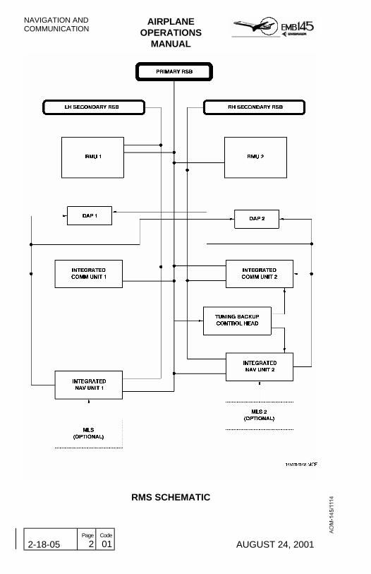
The RMS consists basically of the following major components:
− Remote mounted:− Integrated Navigation Unit (INU)− Integrated Communication Unit (ICU)
− Cockpit Mounted:− 2 Radio Management Unit (RMU)− 1 Tuning Backup Control Head (TBCH)− 3 Digital Audio Panel (DAP)
With the exception of the Digital Audio Panel, all components of theRMS are connected through the digital Radio System Buses (RSB)that allows complete control and information exchange between theunits of the entire RMS. Audio switching control is provided by meansof the controls on the Digital Audio Panel itself. The audio signals aretransmitted from the remote units to the Digital Audio Panel throughdedicated digital audio buses.
The navigation and communication data are displayed on the RMU,PFD and MFD displays.
NAVIGATION ANDCOMMUNICATION
AIRPLANEOPERATIONS
MANUAL
2-18-05 Page
2 Code
01 AUGUST 24, 2001
RMS SCHEMATIC
AIRPLANEOPERATIONS
MANUAL
NAVIGATION ANDCOMMUNICATION
REVISION 29 2-18-07 Page
1 Code
01
INTEGRATED COMMUNICATION UNIT (RCZ-851E)
The Integrated Communication Unit incorporates an internal VHFcommunication transceiver module and the ATC transponder modulewhich interfaces through a cluster module to the Radio System Bus foroperation.
This unit provides digitized audio signals to the Digital Audio Panel andconventional analog audio interfaces to other systems. The followingmodules may be provided in this unit:
− VHF Communication Transceiver Module (TR-850) - This module isa conventional VHF COM transceiver that operates in the frequencyrange of 118 to 136.975 MHz.
− Mode S Diversity Transponder Module (XS-852) - This transponder
module provides full ATCRBS, Mode S and TCAS datacommunications capability. The Mode S Transponder module hasthe encoding and decoding capability required for Mode S operationin addition to the capability to operate as a conventional Air TrafficControl Radio Beacon Service (ATCRBS) transponder. The Mode Soperation allows digital addressing of an individual airplane and thetransmission of messages back and forth between the air and theground.
NAVIGATION ANDCOMMUNICATION
AIRPLANEOPERATIONS
MANUAL
2-18-07 Page
2 Code
01 REVISION 17
THIS PAGE IS LEFT BLANK INTENTIONALLY

AIRPLANEOPERATIONS
MANUAL
NAVIGATION ANDCOMMUNICATION
MARCH 30, 2001 2-18-09 Page
1 Code
01
INTEGRATED NAVIGATION UNIT (RNZ-851)
The Integrated Navigation Unit is a complete self-contained navigationsystem. The system consists of the VOR, localizer, glide slope andmarker beacon receiver modules, the ADF module, a six-channelscanning DME module, and audio digitizers. The system alsoincorporates two L-Band antenna (optional), two ADF antenna(optional), two MB antenna, two VOR/ILS antenna and one GS dualantenna.
The following modules are provided in this unit:
− VHF NAV Receiver Module (NV-850) - The VHF NAV receiver is amodule of the Integrated Navigation Unit and houses the majornavigation functions of the VOR/LOC receiver, glide slope receiverand marker beacon receiver.The ILS meets Category II instrument landing requirements.Housed within the NAV receiver is a glideslope receiver whichprovides 40 channels of glideslope information for the conventionalILS. Also includes a 75 MHz marker beacon receiver which detectsand transmits the tones of the marker beacons to the Audio System.
− DME Transceiver Module (DM-850) - The DME module is asix-channel DME that simultaneously tracks four selected channelsfor distance, groundspeed and time to station as well as monitoringtwo additional channels for the ident functions. This feature gives thesystem the capability of tracking four channels and having thedecoded identifier readily available from two additional channels. Theunit dedicates two of the four selected channels to the FMS (ifinstalled). Thus, with the FMS installed, there are two remainingchannels to control and display ident, distance, time to station andground speed. Even with the FMS installed, the preset or standbyVOR channel, when selected, provides instant station identificationsince it was one of the two additional channel being monitored.
− ADF Receiver Module - The ADF System comprises the ADFreceiver (DF-850) and the companion ADF antenna (AT-860). TheADF receiver operates in the frequency ranges of 100 to 1799.5 kHzand 2181 to 2183 kHz (marine emergency frequency range).

NAVIGATION ANDCOMMUNICATION
AIRPLANEOPERATIONS
MANUAL
2-18-09 Page
2 Code
01 MARCH 30, 2001
THIS PAGE IS LEFT BLANK INTENTIONALLY

AIRPLANEOPERATIONS
MANUAL
NAVIGATION ANDCOMMUNICATION
REVISION 26 2-18-11 Page
1 Code
01
RADIO MANAGEMENT UNIT (RMU)The Radio Management Unit consists of a display and a bezel panelthat provide control of the communications and radio navigationequipment. Additional airplane systems information is also available onspecific RMU selectable pages.
The EMB-145 is equipped with two RMUs, each one responsible forcontrolling the on-side radio equipment (e.g., RMU 1 controls theNAV/COM 1). However, through the cross-side operating mode it ispossible to select the opposite side radio frequencies.
There is no master switch for the RMUs: when the airplane isenergized, both RMUs (and the EICAS) are automatically turned ON.However, only the COM 1 radio is available (dashes on the remainingRMUs fields) until the AVIONICS MASTER is switched ON.
Additionally, in the event of an electrical emergency the RMU is abackup display for the main panel (PFDs and MFDs). In this conditionthe main panel is turned off and the NAVIGATION Backup Page, thatpresents basic navigation information, may be accessed through RMUpage.
RMU PAGES
Available RMU pages are as follows: RADIO Page, NAV and COMMEMORY Pages, ATC/TCAS Control Page, NAVIGATION BackupPage, ENGINE Backup Pages 1 and 2, SYS SELECT Page (COMband options) and MAINTENANCE Page.
Pressing the Page Control Button (PGE) selects the Page Menu.Pressing the Line Select Button associated with the desired page willcause the respective page to be displayed. The RADIO Page will bedisplayed again when the Line Select Button associated with theRETURN TO RADIOS label is pressed.
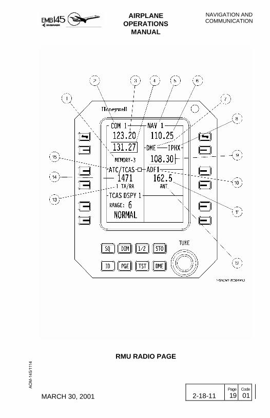
RADIO PAGE
Normally presented after power up, the Radio Page is divided into fivededicated windows. Each window groups the data associated with aparticular function: COM, NAV, ATC/TCAS, ADF and MLS (optional).In addition the windows provide complete control of the frequency andoperating modes of the associated function.

NAVIGATION ANDCOMMUNICATION
AIRPLANEOPERATIONS
MANUAL
2-18-11 Page
2 Code
01 REVISION 29
NAVIGATION/COMMUNICATION MEMORY PAGES
The Memory Page presents two similar displays called First MemoryPage and Second Memory Page. The First Memory Page showsmemory locations 1 through 6 and the Second Memory Page showsmemory location 7 through 12. Both the COM and NAV Memory Pagesare functionally identical.
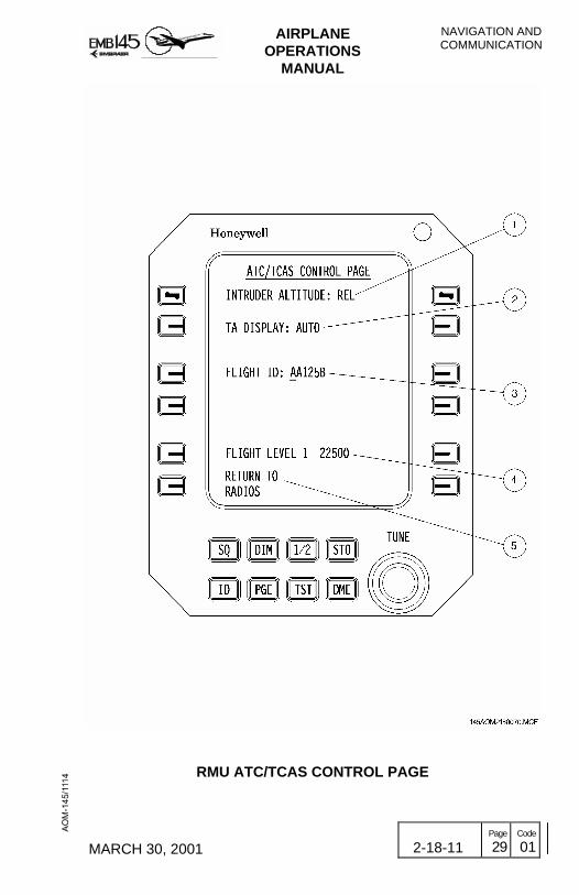
ATC/TCAS CONTROL PAGE
The ATC/TCAS Control Page allows the pilot to select various TCASoperational features:
• Intruder Altitude− REL: Target’s altitude displayed relative to one’s own airplane
(default).− FL: Target’s altitude displayed as flight level (reverts to REL
after 20 sec).• TA Display
− AUTO: Traffic targets displayed only when TA or RA targetconditions exist.
− MANUAL: All traffic targets displayed within the viewingairspace.
• Flight ID Allows Mode S coding to reflect the current flight’s call sign.• Flight Level 1/2
Display of the transponder’s encoded altitude and the air datasource for that altitude.
NAVIGATION BACKUP PAGE
The NAVIGATION Backup Page consists of a backup navigationdisplay that presents HSI, MB, DME, NAV (VOR) and ADF information.
ENGINE BACKUP PAGE
The ENGINE Backup Page displays information normally presented onthe EICAS, as engine and systems indications, as well as EICASmessages. The ENGINE Backup Page is divided into two pages. Thefirst presents only engine indications, while the second presentssystems indications and EICAS messages. For further information onEngine Backup Page refer to Section 2-10 - Powerplant and 2-4 - CrewAwareness.
AIRPLANEOPERATIONS
MANUAL
NAVIGATION ANDCOMMUNICATION
REVISION 29 2-18-11 Page
3 Code
01
SYSTEM SELECT PAGE
The SYS SELECT Page allows the selection of COM 1 and COM 2between Narrow and Wide bands.
MAINTENANCE PAGE
This page displays test results information depending upon the type oftest that is being carried out (power on self-test or pilot activated self-test). Two pages may be presented if a failure is detected, depending ifthe failure is in the RMS or in one of the radios. This page is notavailable in flight.
RMU NORMAL OPERATION
RMU SELF-TEST
On the ground, the RMS performs a self-test each time power isapplied after power off periods greater than 10 seconds. This testmonitors the primary and secondary radio system buses as well as theindividual Radio Systems for proper operation. Each function teststatus is displayed in its respective window.
Under normal conditions, the COM will be operational within 7 secondsafter power on and the remaining radio equipment units within 50seconds. The test can be terminated by pressing the Test Button in theRMU Bezel Panel.
If any bus or radio test parameter failure occurs, an associated errormessage will be displayed on the test failure window, below the COMand NAV windows. Radio System failures are displayed in the firstfailure window and function failures in a second failure window. Thefailure windows may be removed by pressing and holding the TestButton. If the test is successfully completed the RMU will display theRadio Page with the same radio configuration prior to the last powerdown.
NOTE: Any radio equipment that is not powered up when the test isinitiated by the RMU will generate an error message.
NAVIGATION ANDCOMMUNICATION
AIRPLANEOPERATIONS
MANUAL
2-18-11 Page
4 Code
01 REVISION 17
Additionally the pilot may perform a test by pressing the Test Button onthe RMU Bezel Panel which causes the activation of the self-test of thecomponent associated with the window in which the yellow cursor islocated. Upon successful completion of this test, a PASS message willbe displayed for a short time in the window, indicating the successfulcompletion of the test. If this test is not successful completed, an errormessage (ERR) will be displayed in the window.
NOTE: Errors detected by the self-test indicate one or more parameteroutside their self-test limit but may not necessarily indicate non-operation of the function. The pilot should verify the operationof the function.
CROSS-SIDE OPERATION
The RMU is provided with a feature called cross-side operating mode.This feature allows the RMU to be changed from its normal operatingmode of tuning the on-side radio equipment to the mode of tuning theopposite side radio equipment.
The cross-side operation is selected by pressing the cross-sideTransfer Button, labeled 1/2, on the RMU Bezel Panel, with the yellowcursor box in any window, except the ATC/TCAS window. The entireRMU display and operation is transferred from the opposite side to theside that has commanded the Cross-side Operating Mode. If the yellowcursor box is in the ATC/TCAS window, pressing the cross-sideTransfer Button selects which transponder (1 or 2) will be in operation.
In the cross-side operation, the RMU Window/Control Side Ident will bedisplayed in magenta on the side that has selected the operation andany change made will be displayed in yellow on the opposite side RMUto indicate that the change was carried out remotely.

AIRPLANEOPERATIONS
MANUAL
NAVIGATION ANDCOMMUNICATION
JANUARY 21, 2002 2-18-11 Page
5 Code
01
COM OPERATION
The normal COM operation is enabled with the RMU Radio Pagedisplayed. The COM window has two frequency lines. The upper linedisplays the active COM frequency while the lower line displays thepreset frequency. Pressing the Line Select Button associated with thepreset frequency will cause the yellow cursor box to move to enclosethat frequency. In this condition the enclosed preset frequency may bechanged through the Frequency Tuning Knobs. When the FrequencyTuning Knobs are actuated the label MEMORY and the associatedmemory location number, both below the lower frequency line, willchange to a TEMP label indicating that the new preset frequency is notyet stored in the memory of the RMU. Frequency storage may beaccomplished by pressing the Memory Storage Button, labeled STO,on the RMU Bezel Panel. This action will also provide the previousMEMORY label and the associated memory location number toreplace the TEMP label, indicating that the new preset frequency hasbeen stored in the indicated memory location.
Placing the yellow cursor box to enclose the MEMORY label, bypressing a second time the Line Select Button beside the COMwindow, will allow scrolling through the entire RMU stored memory.This may be performed by rotating the Frequency Tuning Knob eitherclockwise to memory location increment or counterclockwise todecrement.
The exchange between the active frequency displayed in the upper lineof the window and the preset frequency displayed in the lower line maybe accomplished by pressing the Frequency Transfer Button on theupper left corner of the RMU Bezel Panel. This effectively causes theCOM to change to the new active frequency that previously was thepreset frequency. In this condition, the previous active frequency dropsdown to the second line of the COM window and becomes a temporarypreset frequency. This is indicated by the TEMP label displayed underthat frequency. The TEMP label also indicates, in this case, that thefrequency displayed in the second line has not been stored in amemory location.
NOTE: The RMU controls the third VHF for airplanes equipped withHoneywell Third VHF System RCZ-833/853 models.

NAVIGATION ANDCOMMUNICATION
AIRPLANEOPERATIONS
MANUAL
2-18-11 Page
6 Code
01 MARCH 30, 2001
• Direct COM TuningDirect COM tuning is accomplished by pressing and holding forapproximately 3 seconds the Line Select Button beside the COMpreset frequency line. The yellow cursor box will enclose the activefrequency allowing direct COM tuning to that frequency, and the presetfrequency line will be blank.
To exit from direct COM tuning, press and hold the Line Select Buttonbeside the preset frequency line, until the preset frequency appears onthe COM window.• Squelch FunctionThe COM squelch function is controlled through the Squelch ControlButton, labeled SQ, on the RMU control bezel. Pressing this button willcause the COM radio to open its squelch and allow any noise or signalpresent in the receiver to be heard in the Audio System. The squelchopen condition is indicated by the SQ label displayed on the top of theCOM window. Pressing the Squelch Control Button again will close theradio squelch immediately.• Automatic Time-OutAfter approximately two minutes of continuous transmission, thetransceiver turns its transmitter off and a beep sound in the audio systemalerts the pilot to the fact. The transceiver then reverts to receiver modein order to prevent a stuck microphone button from blocking thecommunications channel. Should the time-out occur, the pilot can reset itby simply releasing the push to talk button and pressing it again.
AIRPLANEOPERATIONS
MANUAL
NAVIGATION ANDCOMMUNICATION
MARCH 30, 2001 2-18-11 Page
7 Code
01
NAV OPERATION
The NAV operation is identical to the COM operation. However, NAVcontrols are accomplished by actuation of the Frequency TransferButton and the Line Select Button located on the upper RH of the RMUBezel Panel. Furthermore, the NAV window has an additional functioncalled DME Split Tuning Mode. The operation in the DME Split TuningMode is similar to the operation in the DME Hold Mode.
The NAV system also incorporates FMS autotuning capability. Throughthe NAV Memory Page it is possible for the FMS to perform automatictuning of the navigation radios (raw data) along the route by pressingthe upper RH Frequency Transfer Button, which enables or disablesthe FMS autotuning capability. When the VOR or the ILS frequency isautotuned by the FMS, a magenta VOR or ILS frequency and amagenta AUTO label will be displayed on the top border of the RADIOPage NAV window.
DME OPERATION
In the normal DME operations only one of the six DME channels ispaired with the VOR active frequency and one other with the presetVOR frequency. However, pressing the DME Select Button, labeledDME, on the RMU Bezel Panel, will enable the DME to be tunedindependently of the VOR active frequency.
Pressing the DME Select Button once will cause the NAV window tosplit into two windows. The top window will display the active VORfrequency and the lower window, with the DME label, will display theactive DME frequency in VHF format. When the NAV window is split,an H (DME Hold) label is displayed in the DME window to indicate thatthe DME is not paired with the active VOR/ILS frequency. In this casethe DME hold condition will also be announced on the PFD. In thiscondition, the DME may be tuned directly by simply pressing theassociated Line Select Button beside the DME window and tuning thenew DME channel through the Frequency Tuning Knobs.
Pressing the DME Select Button again will cause the frequency to bedisplayed in the channel format (TACAN).
Pressing the DME Select Button for the third time will cause the NAVwindow to resume its normal mode with the active and presetfrequencies being displayed while returning the DME to the condition ofchanneling with the active VOR frequency.

NAVIGATION ANDCOMMUNICATION
AIRPLANEOPERATIONS
MANUAL
2-18-11 Page
8 Code
01 MARCH 30, 2001
ADF OPERATION
The tuning of ADF frequencies is similar to that performed on theairplane’s other radios equipment. Pressing the Line Select Buttonbeside the ADF frequency display will move the yellow cursor box tosurround the ADF frequency in the RMU display. Then, slowly turningthe Frequency Tuning Inner Knob clockwise causes the ADFfrequencies to advance in 0.5 kHz increments while slowly turning theouter knob clockwise will cause the frequencies to advance in 10 kHzincrements. ADF tuning through the Frequency Tuning Knobs isaccomplished using proportional rate. If the knobs are turned in slowdeliberate steps the frequency will follow likewise. However, if the knobis turned rapidly, the frequency will skip several steps, depending uponthe speed at which the knob is turned. This allows accomplishing largefrequency changes with a very slight rotation of the knob.
The RMU also has the capability of storing an ADF frequency. This isaccomplished by selecting the desired ADF frequency and thenpressing the Memory Storage Button on the RMU Bezel Panel. Toretrieve the stored frequency from memory, the ADF frequency LineSelect Button must be pressed for 2 seconds.
The ADF is provided with a mode control capability. ADF operationalmodes can be selected by moving the yellow cursor box to the ADFmodes field in the ADF window and then pressing the Line SelectButton beside the ADF modes field or rotating the Frequency TuningKnobs. Repeatedly pressing the Line Select Button will cause themodes to step in one direction while rotating the Frequency TuningKnobs will select the modes either up or down the current location.
The ADF operational modes are the following:
- ANT - The ADF receives signal only.- ADF - The ADF receives signal and calculates relative bearings to
station.- BFO - The ADF adds a beat frequency oscillator for reception of
CW signals.- VOICE - The ADF opens width of IF bandwidth for better aural
reception.
NOTE: Bearing information is available in the ADF and BFO modesonly.

AIRPLANEOPERATIONS
MANUAL
NAVIGATION ANDCOMMUNICATION
REVISION 29 2-18-11 Page
9 Code
01
TRANSPONDER AND TCAS OPERATION
Transponder operation is similar to other radio equipment since itrequires moving the yellow cursor box to a desired function. In order totune a desired ATC code, press the Line Select beside the ATC codedisplay. This action will enable the Frequency Tuning Knobs to changethe ATC codes. The outer knob sets the thousands and hundredsdigits and the inner knob sets the tens and ones digits.
Pressing and holding the code Line Select Button will recall the storedpreset code (typically used for VFR). A new code may be stored bysetting the code and then pressing the Memory Storage Button on theRMU Bezel Panel.
Pressing the Line Select Button associated with the transponderoperating mode display will move the yellow cursor box to surround themode annunciation in the ATC/TCAS window allowing to set a newtransponder mode if a non-standby mode is selected. Once the modeannunciation is surrounded, pressing the Transfer Button 1/2 will selectwhich transponder will be in operation (e.g., 1 ATC ON to 2 ATC ON).
The transponder operational modes are the following:
− ATC ON - Replies on Modes S and A, no altitude reporting.− ATC ALT - Replies on Modes A, C and S, with altitude reporting.− TA ONLY - TCAS Advisory Mode is selected.− TA/RA - TCAS Traffic Advisory/Resolution Advisory Mode is selected.
ABNORMAL RMU OPERATION
Loss of the Primary Radio System Bus will disable the cross-sidecontrol capability and also the TBCH. However, no radio functions willbe lost. The radios on both sides will still be functional through theSecondary Radio System Buses.
Loss of the left and/or right Secondary Radio System Bus will notdisable the radio functions. The radios may be tuned, in this condition,through the Primary Radio System Bus or through the cross-sidecontrol feature.
As a safety feature of the RMU, if any component of the Radio Systemfails to respond to the commands from the RMU, the frequencies orthe operating commands associated with that particular function will beremoved from the RMU display and replaced with dashes.

NAVIGATION ANDCOMMUNICATION
AIRPLANEOPERATIONS
MANUAL
2-18-11 Page
10 Code
01 REVISION 17
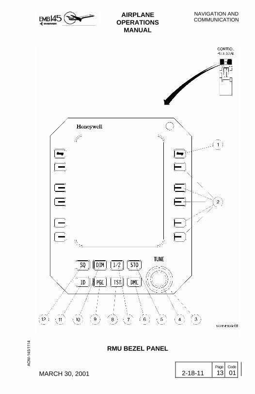
RMU CONTROLS AND INDICATORS
RMU BEZEL PANEL
1 - FREQUENCY TRANSFER BUTTON− When pressed, the active frequency (upper line) and the preset
frequency (lower line) in the COM or NAV windows exchangelocation and function.
2 - LINE SELECT BUTTONS− The first press of the button moves a yellow cursor box to
surround the data field associated with that particular Line SelectButton. This enables the Frequency Tuning Knobs to change thedata or the mode marked by the cursor. For some functions,additional pressing of the Line Select Button will toggle modes orrecall stored frequencies. The Line Select Buttons, if keptpressed, allows ADF and ATC memories to be recalled, and toenter or exit Direct Tune Mode for COM and NAV.
3 - FREQUENCY TUNING OUTER KNOB − Allows the data field enclosed by the cursor to be modified. The
data may be frequency setting, stored frequencies or mode,depending upon the data field. When setting a frequency, thisknob controls the digits to the left of the decimal point.Furthermore, this knob also controls the RMU brightness, whichis enabled by pressing the Dimming Button.
4 - FREQUENCY TUNING INNER KNOB − Is functionally similar to the Frequency Tuning Outer Knob
except that when setting the frequency, this knob controls thedigits to the right of the decimal point.
5 - MEMORY STORAGE BUTTON− Pressing this button will cause a temporary (TEMP) COM or
NAV pre-select frequency to be stored in the memory andassigned numbered location, provided the cursor has first beenplaced around that frequency.NOTE: ADF and ATC have only one memory location.

AIRPLANEOPERATIONS
MANUAL
NAVIGATION ANDCOMMUNICATION
MARCH 30, 2001 2-18-11 Page
11 Code
01
6 - DME SELECT BUTTON− Allows selection of the DME Hold Mode, tuning a different DME
channel, not paired with the VOR/ILS frequency, without changingthe active VOR frequency. Repeated pressing of this buttonenables display and selection of the DME channels in VHF andTACAN formats, and then back to the paired VOR/DME mode.
7 - CROSS-SIDE TRANSFER BUTTON− With the cursor in any window, except the ATC or TCAS display,
pressing this button will transfer the entire RMU operation anddisplay from the cross-side system.
− With the cursor in the ATC or TCAS window, pressing thisbutton selects which transponder will be in operation.
− With enhanced TCAS, the button allows control of TCAS data inthe cross-side display.
8 - TEST BUTTON− When pressed, causes the component associated with the
present position of the yellow cursor box to activate its internalself-test circuits for a complete end-to-end test of the function.To properly accomplish the equipment self-test, the Test Buttonmust be pressed and held down as follows:− About 2 seconds for COM transceiver self-test.− From 5 to 7 seconds for DME, ATC and ADF self-test.− About 20 seconds for NAV (VOR/ILS) self-test.
− Releasing the Test Button at any time immediately returns theequipment to its normal operation in the actual function.
− If the Test Button is held pressed for 30 seconds or more, theradios are automatically commanded back into normal operation.
9 - PAGE CONTROL BUTTON− Provides access to the page menu.
10 - DIMMING BUTTON − The RMU features an automatic screen brightness adjustment,
within a limited range, to keep the display visibility optimized.The Dimming Button enables RMU brightness to be controlledmanually through the Frequency Tuning Outer Knob. Themanual dimming control can be disabled by pressing theDimming Button again or any Line Select Button.

NAVIGATION ANDCOMMUNICATION
AIRPLANEOPERATIONS
MANUAL
2-18-11 Page
12 Code
01 MARCH 30, 2001
11 - TRANSPONDER IDENTIFICATION MODE BUTTON − Selects the Transponder Identification Response Mode. The
ident squawk will stop after 18 seconds.
12 - SQUELCH CONTROL BUTTON − Causes the COM radio to open its squelch allowing any noise
or signal present in the radio to be heard in the Audio System.The label SQ is displayed on the top line of the COM windowwhen the squelch is open. When pressed a second time theSquelch Control Button closes the squelch.
AIRPLANEOPERATIONS
MANUAL
NAVIGATION ANDCOMMUNICATION
MARCH 30, 2001 2-18-11 Page
13 Code
01
RMU BEZEL PANEL

NAVIGATION ANDCOMMUNICATION
AIRPLANEOPERATIONS
MANUAL
2-18-11 Page
14 Code
01 MARCH 30, 2001
RMU DISPLAY
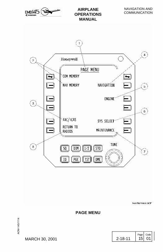
PAGE MENU
1 - PAGE MENU IDENTIFICATION− Indicates that Page MENU is selected.− Color: White.
2 - COM AND NAV MEMORY PAGE LABEL− To access the COM or NAV MEMORY Pages press the Line
Select Button adjacent to the desired page.− Color: Green.
3 - ATC/TCAS PAGE LABEL− To access the ATC/TCAS Page press the Line Select Button
adjacent to this label.− Color: Green.
4 - NAVIGATION PAGE LABEL− To access the NAVIGATION Page press the Line Select Button
adjacent to this label.− Color: Green.
5 - ENGINE PAGE LABEL− To access the ENGINE Page press the Line Select Button
adjacent to this label.− Color: Green.
6 - SYS SELECT PAGE LABEL− To access the SYS SELECT Page press the Line Select Button
adjacent to this label.− Color: Green.
7 - MAINTENANCE PAGE LABEL− To access the MAINTENANCE Page press the Line Select
Button adjacent to this label.− Color: Green.
8 - RETURN TO RADIOS PAGE LABEL− To return to the RADIOS Page press the Line Select Button
adjacent to this label.− Color: Green.
AIRPLANEOPERATIONS
MANUAL
NAVIGATION ANDCOMMUNICATION
MARCH 30, 2001 2-18-11 Page
15 Code
01
PAGE MENU

NAVIGATION ANDCOMMUNICATION
AIRPLANEOPERATIONS
MANUAL
2-18-11 Page
16 Code
01 MARCH 30, 2001
RADIO PAGE
1 - PRESET FREQUENCY MEMORY LOCATION (ONLY FOR NAVAND COM WINDOWS)− Identifies the preset frequency as temporary (TEMP label) or
retrieved from the memory (MEMORY label followed by itsmemory location).
− Colors:− Cyan for on-side operation.− Yellow for cross-side operation.
− When marked by the yellow cursor box, the memory locationlabels and their associated stored frequencies can be scrolledby using the Frequency Tuning Knobs.
2 - COM WINDOW/CONTROL SIDE IDENTIFICATION− Identifies the window and which source equipment (side 1 or 2)
is active in that RMU.− Colors:
− White for on-side source.− Magenta for cross-side source.
3 - VHF COM ACTIVE FREQUENCY− Indicates the active frequency for that window.− Colors:
− White for on-side operation.− Yellow for cross-side operation.
− Digits are replaced by dashes in case of any failure in theassociated source.
4 - VHF COM PRESET FREQUENCY− Indicates the preset frequency.− Colors:
− Cyan for on-side operation.− Yellow for cross-side operation.
NOTE: When DME Hold is not selected, the NAV Window alsopresents a similar preset frequency field.
AIRPLANEOPERATIONS
MANUAL
NAVIGATION ANDCOMMUNICATION
MARCH 30, 2001 2-18-11 Page
17 Code
01
5 - NAV WINDOW/CONTROL SIDE IDENTIFICATION− Identifies the window and which source equipment (side 1 or 2)
is active in that RMU.− Colors:
− White for on-side source.− Magenta for cross-side source.
6 - VHF NAV ACTIVE FREQUENCY− Indicates the active frequency for that window.− Colors:
− White for on-side operation.− Yellow for cross-side operation.
− Digits are replaced by dashes in case of any failure in theassociated source.
7 - DME HOLD MODE ANNUNCIATION− Indicates that the DME is in Hold Mode and the active DME
channel is selected separately from the active VOR/ILSfrequency.
− Color: Yellow.
8 - DME STATION IDENTIFICATION CODE− Displays the digital identification code of the ground station to
which the DME is tuned with.− Color: White.
9 - DME HOLD MODE FREQUENCY− Indicates the active frequency in DME Hold Mode operation, in
VHF (represented) or TACAN formats.− Color: White.
10 - ADF WINDOW/CONTROL SIDE IDENTIFICATION− Identifies the window and which source equipment (side 1 or 2)
is active in that RMU.− Colors:
− White for on-side source.− Magenta for cross-side source.
NAVIGATION ANDCOMMUNICATION
AIRPLANEOPERATIONS
MANUAL
2-18-11 Page
18 Code
01 MARCH 30, 2001
11 - ADF ACTIVE FREQUENCY− Indicates the active frequency for that window.− Colors:
− White for on-side operation.− Yellow for cross-side operation.
− Digits are replaced by dashes in case of any failure in theassociated source.
12 - ADF MODES FIELD− Displays the ADF modes as selected either through the
second ADF Line Select Button (achieved by repeatedpressing) or through the Frequency Tuning Knobs when theyellow cursor box is located in this field.
− Color: Green.
13 - TRANSPONDER OPERATING MODE ANNUNCIATION− Displays the active transponder operating mode as selected
through the Frequency Tuning Knobs when the yellow cursorbox is located in this field. Pressing the Line Select Buttonbeside this field will alternate between the pre-selectedtransponder mode and the standby mode.
− Color: Green.
14 - ATC CODE− Displays the active ATC code number.− Color: White.
15 - ATC/TCAS WINDOW− Identifies the window as the ATC/TCAS window.− Colors: White.
AIRPLANEOPERATIONS
MANUAL
NAVIGATION ANDCOMMUNICATION
MARCH 30, 2001 2-18-11 Page
19 Code
01
RMU RADIO PAGE
NAVIGATION ANDCOMMUNICATION
AIRPLANEOPERATIONS
MANUAL
2-18-11 Page
20 Code
01 MARCH 30, 2001
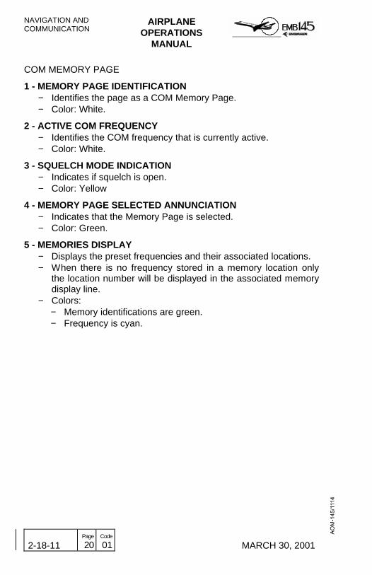
COM MEMORY PAGE
1 - MEMORY PAGE IDENTIFICATION− Identifies the page as a COM Memory Page.− Color: White.
2 - ACTIVE COM FREQUENCY− Identifies the COM frequency that is currently active.− Color: White.
3 - SQUELCH MODE INDICATION− Indicates if squelch is open.− Color: Yellow
4 - MEMORY PAGE SELECTED ANNUNCIATION− Indicates that the Memory Page is selected.− Color: Green.
5 - MEMORIES DISPLAY− Displays the preset frequencies and their associated locations.− When there is no frequency stored in a memory location only
the location number will be displayed in the associated memorydisplay line.
− Colors:− Memory identifications are green.− Frequency is cyan.

AIRPLANEOPERATIONS
MANUAL
NAVIGATION ANDCOMMUNICATION
MARCH 30, 2001 2-18-11 Page
21 Code
01
6 - MEMORY INSERT PROMPT− If it is desirable to insert a new frequency in a particular memory
location, simply press the Line Select Button beside the locationline, moving the yellow cursor box to that line. Then press theLine Select Button beside the Insert prompt label. This willcause all the data in memory from the insert location downwardto shift one position down. The cursor will remain in the insertionselected location allowing the new frequency to be tuned andstored in that memory location. A MEM FULL (Memory Full)annunciation will be displayed in the RMU display if the 12memory locations are filled and the Line Select Buttonassociated with the Insert prompt is pressed.
− Color: Green.
7 - MEMORY DELETE PROMPT− To delete a frequency from the memory, press the Line Select
Button adjacent to the line associated with the frequency to bedeleted. Then press the Line Select Button adjacent to theDelete prompt. The frequency enclosed by the cursor will bedeleted from the memory. Higher numbered memory locationswill then move upward to fill the empty memory location.
− Color: Green.
8 - RADIO PAGE RETURN PROMPT− Pressing the associated Line Select Button will return the RMU
display to the Radio Page.− Color: Green.
9 - MEMORY MORE PROMPT− The More prompt allows to display memory locations 7 through
12, by pressing the associated Line Select Button. All actionsdescribed for memory locations 1 through 6 are also applicableto memory locations 7 through 12. If locations 1 through 6 arenot filled, the Second Memory Page will not be accessible.
− Color: Green.

NAVIGATION ANDCOMMUNICATION
AIRPLANEOPERATIONS
MANUAL
2-18-11 Page
22 Code
01 MARCH 30, 2001
THIS PAGE IS LEFT BLANK INTENTIONALLY

AIRPLANEOPERATIONS
MANUAL
NAVIGATION ANDCOMMUNICATION
REVISION 17 2-18-11 Page
23 Code
01
RMU COM MEMORY PAGE
NAVIGATION ANDCOMMUNICATION
AIRPLANEOPERATIONS
MANUAL
2-18-11 Page
24 Code
01 REVISION 29
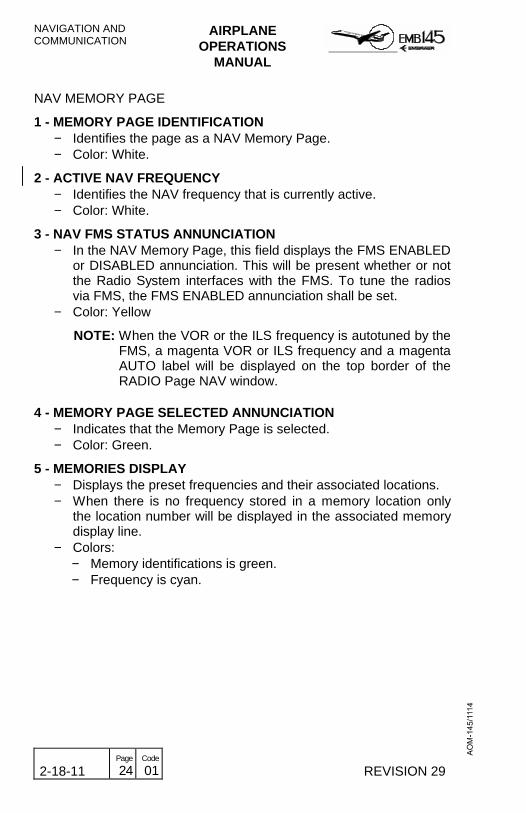
NAV MEMORY PAGE
1 - MEMORY PAGE IDENTIFICATION− Identifies the page as a NAV Memory Page.− Color: White.
2 - ACTIVE NAV FREQUENCY− Identifies the NAV frequency that is currently active.− Color: White.
3 - NAV FMS STATUS ANNUNCIATION− In the NAV Memory Page, this field displays the FMS ENABLED
or DISABLED annunciation. This will be present whether or notthe Radio System interfaces with the FMS. To tune the radiosvia FMS, the FMS ENABLED annunciation shall be set.
− Color: Yellow
NOTE: When the VOR or the ILS frequency is autotuned by theFMS, a magenta VOR or ILS frequency and a magentaAUTO label will be displayed on the top border of theRADIO Page NAV window.
4 - MEMORY PAGE SELECTED ANNUNCIATION− Indicates that the Memory Page is selected.− Color: Green.
5 - MEMORIES DISPLAY− Displays the preset frequencies and their associated locations.− When there is no frequency stored in a memory location only
the location number will be displayed in the associated memorydisplay line.
− Colors:− Memory identifications is green.− Frequency is cyan.

AIRPLANEOPERATIONS
MANUAL
NAVIGATION ANDCOMMUNICATION
MARCH 30, 2001 2-18-11 Page
25 Code
01
6 - MEMORY INSERT PROMPT− If it is desirable to insert a new frequency in a particular memory
location, simply press the Line Select Button beside the locationline, moving the yellow cursor box to that line. Then press theLine Select Button beside the Insert prompt label. This willcause all the data in memory from the insert location downwardto shift one position down. The cursor will remain in the insertionselected location allowing the new frequency to be tuned andstored in that memory location. A MEM FULL (Memory Full)annunciation will be displayed in the RMU display if the 12memory locations are filled and the Line Select Buttonassociated with the Insert prompt is pressed.
− Color: Green.
7 - MEMORY DELETE PROMPT− To delete a frequency from the memory, press the Line Select
Button adjacent to the line associated with the frequency to bedeleted. Then press the Line Select Button adjacent to theDelete prompt. The frequency enclosed by the cursor will bedeleted from the memory. Higher numbered memory locationswill then move upward to fill the empty memory location.
− Color: Green.
8 - RADIO PAGE RETURN PROMPT− Pressing the associated Line Select Button will return the RMU
display to the Radio Page.− Color: Green.
9 - MEMORY MORE PROMPT− The More prompt allows to display memory locations 7 through
12, by pressing the associated Line Select Button. All actionsdescribed for memory locations 1 through 6 are also applicableto memory locations 7 through 12. If locations 1 through 6 arenot filled, the Second Memory Page will not be accessible.
− Color: Green.

NAVIGATION ANDCOMMUNICATION
AIRPLANEOPERATIONS
MANUAL
2-18-11 Page
26 Code
01 MARCH 30, 2001
THIS PAGE IS LEFT BLANK INTENTIONALLY

AIRPLANEOPERATIONS
MANUAL
NAVIGATION ANDCOMMUNICATION
REVISION 17 2-18-11 Page
27 Code
01
RMU NAV MEMORY PAGE

NAVIGATION ANDCOMMUNICATION
AIRPLANEOPERATIONS
MANUAL
2-18-11 Page
28 Code
01 REVISION 29
ATC/TCAS CONTROL PAGE
1 - INTRUDER ALTITUDE DISPLAY− REL (green): Target’s altitude displayed relative to one’s own
airplane (default).− FL (cyan): Target’s altitude displayed as flight level (reverts to
REL after 20 sec).
2 - TA DISPLAY− AUTO (green): Traffic targets displayed only when TA or RA
target condition exists.− MANUAL (cyan): All traffic targets displayed within the viewing
airspace.
3 - FLIGHT ID− Allows Mode S coding to reflect the current flight’s call sign. The
outer tuning knob moves the character position designator andthe inner tuning knob selects the desired alphanumericcharacter.
− Color: White
4 - FLIGHT LEVEL 1/2− Display of the transponder’s encoded altitude and the air data
source for that altitude.− Color: Green.
5 - RADIO PAGE RETURN PROMPT− Pressing the associated Line Select Button will return the RMU
display to the Radio Page.− Color: Green.
AIRPLANEOPERATIONS
MANUAL
NAVIGATION ANDCOMMUNICATION
MARCH 30, 2001 2-18-11 Page
29 Code
01
RMU ATC/TCAS CONTROL PAGE

NAVIGATION ANDCOMMUNICATION
AIRPLANEOPERATIONS
MANUAL
2-18-11 Page
30 Code
01 MARCH 30, 2001
NAVIGATION BACKUP PAGE
NOTE: - The navigation information presented on the NavigationBackup Page are operationally identical to that normallypresented on the PFD.
- The compass card is presented only in arc partial format.
- The selected course and the DME distance to station areboxed.
- NAV and ADF active frequencies are also presented.
1 - ACTIVE NAV FREQUENCY
2 - BEARING 1 POINTER
3 - BEARING 2 POINTER
4 - ACTIVE ADF FREQUENCY
5 - COURSE DEVIATION BAR
6 - COURSE DEVIATION SCALE
7 - DME DISTANCE TO STATION
8 - MARKER BEACON DISPLAY
9 - SELECTED COURSE
10 - BEARING 2 SOURCE ANNUNCIATION
11 - BEARING 1 SOURCE ANNUNCIATION
12 - COMPASS CARD DISPLAY

AIRPLANEOPERATIONS
MANUAL
NAVIGATION ANDCOMMUNICATION
MARCH 30, 2001 2-18-11 Page
31 Code
01
RMU NAV BACKUP PAGE
NAVIGATION ANDCOMMUNICATION
AIRPLANEOPERATIONS
MANUAL
2-18-11 Page
32 Code
01 DECEMBER 20, 2002
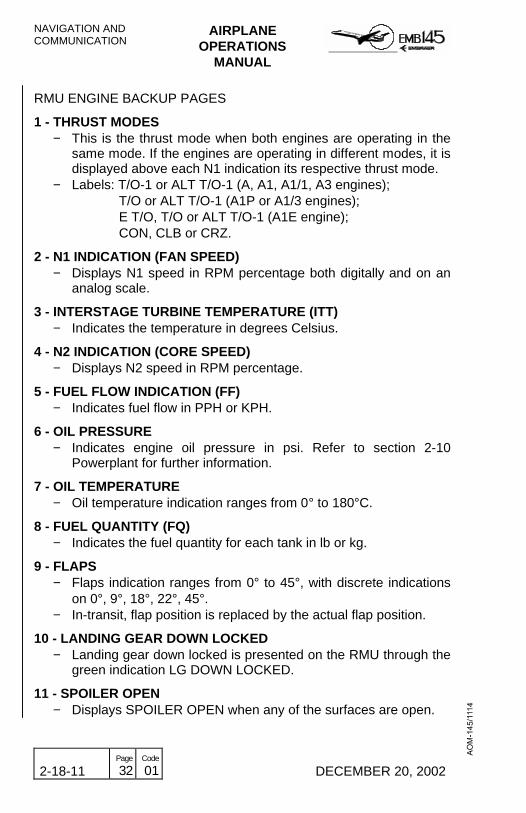
RMU ENGINE BACKUP PAGES
1 - THRUST MODES− This is the thrust mode when both engines are operating in the
same mode. If the engines are operating in different modes, it isdisplayed above each N1 indication its respective thrust mode.
− Labels: T/O-1 or ALT T/O-1 (A, A1, A1/1, A3 engines); T/O or ALT T/O-1 (A1P or A1/3 engines); E T/O, T/O or ALT T/O-1 (A1E engine); CON, CLB or CRZ.
2 - N1 INDICATION (FAN SPEED)− Displays N1 speed in RPM percentage both digitally and on an
analog scale.
3 - INTERSTAGE TURBINE TEMPERATURE (ITT)− Indicates the temperature in degrees Celsius.
4 - N2 INDICATION (CORE SPEED)− Displays N2 speed in RPM percentage.
5 - FUEL FLOW INDICATION (FF)− Indicates fuel flow in PPH or KPH.
6 - OIL PRESSURE− Indicates engine oil pressure in psi. Refer to section 2-10
Powerplant for further information.
7 - OIL TEMPERATURE− Oil temperature indication ranges from 0° to 180°C.
8 - FUEL QUANTITY (FQ)− Indicates the fuel quantity for each tank in lb or kg.
9 - FLAPS− Flaps indication ranges from 0° to 45°, with discrete indications
on 0°, 9°, 18°, 22°, 45°.− In-transit, flap position is replaced by the actual flap position.
10 - LANDING GEAR DOWN LOCKED− Landing gear down locked is presented on the RMU through the
green indication LG DOWN LOCKED.
11 - SPOILER OPEN− Displays SPOILER OPEN when any of the surfaces are open.

AIRPLANEOPERATIONS
MANUAL
NAVIGATION ANDCOMMUNICATION
DECEMBER 20, 2002 2-18-11 Page
32A Code
01
RMU ENGINE BACKUP PAGES
NAVIGATION ANDCOMMUNICATION
AIRPLANEOPERATIONS
MANUAL
2-18-11 Page
32B Code
01 DECEMBER 20, 2002
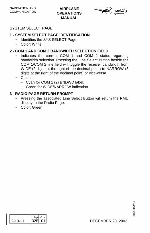
SYSTEM SELECT PAGE
1 - SYSTEM SELECT PAGE IDENTIFICATION− Identifies the SYS SELECT Page.− Color: White.
2 - COM 1 AND COM 2 BANDWIDTH SELECTION FIELD− Indicates the current COM 1 and COM 2 status regarding
bandwidth selection. Pressing the Line Select Button beside theCOM 1/COM 2 line field will toggle the receiver bandwidth fromWIDE (2 digits at the right of the decimal point) to NARROW (3digits at the right of the decimal point) or vice-versa.
− Color:− Cyan for COM 1 (2) BNDWD label.− Green for WIDE/NARROW indication.
3 - RADIO PAGE RETURN PROMPT− Pressing the associated Line Select Button will return the RMU
display to the Radio Page.− Color: Green.

AIRPLANEOPERATIONS
MANUAL
NAVIGATION ANDCOMMUNICATION
MARCH 30, 2001 2-18-11 Page
33 Code
01
RMU SYSTEM SELECT PAGE
NAVIGATION ANDCOMMUNICATION
AIRPLANEOPERATIONS
MANUAL
2-18-11 Page
34 Code
01 MARCH 30, 2001
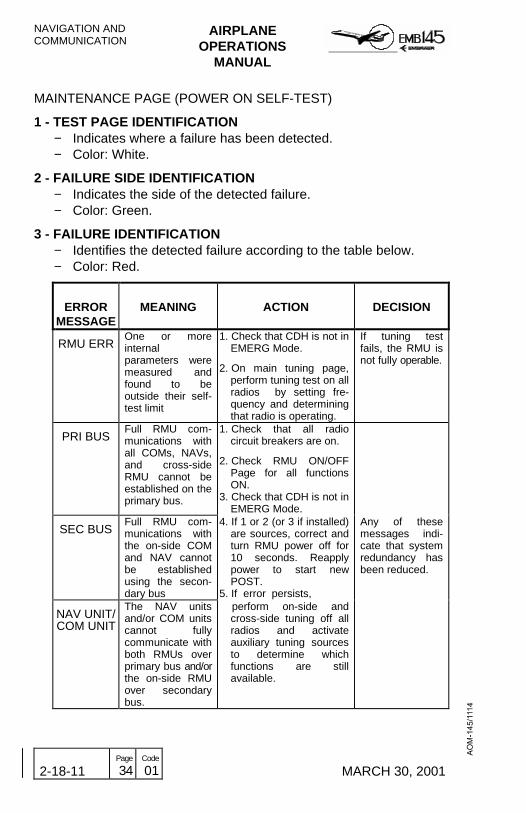
MAINTENANCE PAGE (POWER ON SELF-TEST)
1 - TEST PAGE IDENTIFICATION− Indicates where a failure has been detected.− Color: White.
2 - FAILURE SIDE IDENTIFICATION− Indicates the side of the detected failure.− Color: Green.
3 - FAILURE IDENTIFICATION− Identifies the detected failure according to the table below.− Color: Red.
ERRORMESSAGE
MEANING ACTION DECISION
RMU ERROne or moreinternalparameters weremeasured andfound to beoutside their self-test limit
1. Check that CDH is not inEMERG Mode.
2. On main tuning page,perform tuning test on allradios by setting fre-quency and determiningthat radio is operating.
If tuning testfails, the RMU isnot fully operable.
PRI BUSFull RMU com-munications withall COMs, NAVs,and cross-sideRMU cannot beestablished on theprimary bus.
1. Check that all radiocircuit breakers are on.
2. Check RMU ON/OFFPage for all functionsON.
3. Check that CDH is not inEMERG Mode.
SEC BUSFull RMU com-munications withthe on-side COMand NAV cannotbe establishedusing the secon-dary bus
4. If 1 or 2 (or 3 if installed)are sources, correct andturn RMU power off for10 seconds. Reapplypower to start newPOST.
5. If error persists,
Any of thesemessages indi-cate that systemredundancy hasbeen reduced.
NAV UNIT/COM UNIT
The NAV unitsand/or COM unitscannot fullycommunicate withboth RMUs overprimary bus and/orthe on-side RMUover secondarybus.
perform on-side andcross-side tuning off allradios and activateauxiliary tuning sourcesto determine whichfunctions are stillavailable.

AIRPLANEOPERATIONS
MANUAL
NAVIGATION ANDCOMMUNICATION
MARCH 30, 2001 2-18-11 Page
35 Code
01
RMU MAINTENANCE PAGE (POWER ON SELF TEST)

NAVIGATION ANDCOMMUNICATION
AIRPLANEOPERATIONS
MANUAL
2-18-11 Page
36 Code
01 MARCH 30, 2001
MAINTENANCE PAGE (PILOT ACTIVATED SELF TEST)
1 - SYSTEM TEST IDENTIFICATION− Indicates which unit is being tested.− Color: Amber.
2 - TEST RESULT INDICATION− Indicates whether the tested system is operating normally or not.− Color:
− Green for successful tests.− Red for unsuccessful tests.

AIRPLANEOPERATIONS
MANUAL
NAVIGATION ANDCOMMUNICATION
MARCH 30, 2001 2-18-11 Page
37 Code
01
RMU MAINTENANCE PAGE (PILOT ACTIVATED SELF TEST)

NAVIGATION ANDCOMMUNICATION
AIRPLANEOPERATIONS
MANUAL
2-18-11 Page
38 Code
01 MARCH 30, 2001
THIS PAGE IS LEFT BLANK INTENTIONALLY

AIRPLANEOPERATIONS
MANUAL
NAVIGATION ANDCOMMUNICATION
MARCH 30, 2001 2-18-13 Page
1 Code
01
TUNING BACKUP CONTROL HEAD
The Tuning Backup Control Head is a unit that provides an alternativemeans of tuning the NAV 2 and COM 2.
The TBCH is energized only when the AVIONICS MASTER is switchedON, and in normal operation it displays the RMU 2 NAV and COMactive frequencies (NAV 2 and COM 2).
NORMAL MODE
In the Normal Mode, the TBCH displays the RMU 2 NAV and COMactive frequencies. Each time these frequencies are tuned via RMU,the TBCH display is updated automatically. The same occurs whenthese frequencies are tuned via TBCH, the RMU 2 NAV and COMactive frequencies being also updated automatically.
It is also possible to tune the RMU 1 NAV and COM active frequenciesusing the RMU cross-side operational mode (see 2-18-11, page 4).
EMERGENCY MODE
When the TBCH is set to the Emergency Mode, the RadioManagement System will accept only the NAV and COM tuning viaTBCH, ignoring the RMUs control.
The RMUs will recover their capability of tuning the radio frequenciesonly when the TBCH is set to the Normal Mode again.
SELF TEST
After power up, the Tuning Backup Control Head performs a self-test.This test consists of saving the frequencies that the COM and NAVunits are tuned to as indicated by the Radio System Bus (RSB), andthen changing the frequency outputs to the COM and NAV andverifying that they have changed on the RSB. Failures are announcedin the display line associated with the function as an error messagefollowed by an error code “ERXX”, with the “XX” showing a two-digiterror code.This test is performed only on the ground, when the unit is turned on.

NAVIGATION ANDCOMMUNICATION
AIRPLANEOPERATIONS
MANUAL
2-18-13 Page
2 Code
01 MARCH 30, 2001
TBCH CONTROLS AND INDICATORS
1 - SYSTEM INSTALLATION ANNUNCIATION− Indicates to which Radio System the Tuning Backup Control
Head is connected.
2 - REMOTE TUNE ANNUNCIATION− Indicates that radio is tuned from a source other than the Tuning
Backup Control Head.− Presented only when the unit is strapped for NAV only or COM
only tuning.
3 - TUNING CURSOR− Indicates which frequency may be changed by the Tuning
Knobs.
4 - NAV AUDIO ON ANNUNCIATION− Indicates that the NAV audio is selected on.
5 - EMERGENCY MODE ANNUNCIATION− Indicates when the unit has been selected to the Emergency
Mode, which inhibits RMU tuning capability.
NOTE: - This annunciation is not related to the emergency COMfrequency of 121.5 MHz.
6 - SQUELCH ANNUNCIATION− Indicates that the squelch is opened by the SQ Switch.
7 - TRANSMIT ANNUNCIATION− Indicates that the COM transmitter is ON.
8 - NAV AUDIO BUTTON− Toggles NAV audio on and off.
9 - SQUELCH BUTTON− Toggles the COM squelch on and off.
10 - TUNING KNOBS− Change the frequency indicated by the tuning cursor.− Inner knob changes the frequency decimal digits in steps of
0.025 MHz for VHF and 0.050 MHz for VOR/LOC.
AIRPLANEOPERATIONS
MANUAL
NAVIGATION ANDCOMMUNICATION
MARCH 30, 2001 2-18-13 Page
3 Code
01
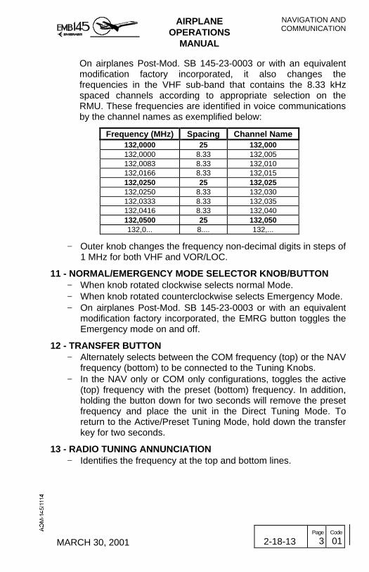
On airplanes Post-Mod. SB 145-23-0003 or with an equivalentmodification factory incorporated, it also changes thefrequencies in the VHF sub-band that contains the 8.33 kHzspaced channels according to appropriate selection on theRMU. These frequencies are identified in voice communicationsby the channel names as exemplified below:
Frequency (MHz) Spacing Channel Name132,0000 25 132,000132,0000 8.33 132,005132,0083 8.33 132,010132,0166 8.33 132,015132,0250 25 132,025132,0250 8.33 132,030132,0333 8.33 132,035132,0416 8.33 132,040132,0500 25 132,050132,0... 8.... 132,...
− Outer knob changes the frequency non-decimal digits in steps of1 MHz for both VHF and VOR/LOC.
11 - NORMAL/EMERGENCY MODE SELECTOR KNOB/BUTTON− When knob rotated clockwise selects normal Mode.− When knob rotated counterclockwise selects Emergency Mode.− On airplanes Post-Mod. SB 145-23-0003 or with an equivalent
modification factory incorporated, the EMRG button toggles theEmergency mode on and off.
12 - TRANSFER BUTTON− Alternately selects between the COM frequency (top) or the NAV
frequency (bottom) to be connected to the Tuning Knobs.− In the NAV only or COM only configurations, toggles the active
(top) frequency with the preset (bottom) frequency. In addition,holding the button down for two seconds will remove the presetfrequency and place the unit in the Direct Tuning Mode. Toreturn to the Active/Preset Tuning Mode, hold down the transferkey for two seconds.
13 - RADIO TUNING ANNUNCIATION− Identifies the frequency at the top and bottom lines.

NAVIGATION ANDCOMMUNICATION
AIRPLANEOPERATIONS
MANUAL
2-18-13 Page
4 Code
01 MARCH 30, 2001
THIS PAGE IS LEFT BLANK INTENTIONALLY

AIRPLANEOPERATIONS
MANUAL
NAVIGATION ANDCOMMUNICATION
AUGUST 24, 2001 2-18-13 Page
5 Code
01
TUNING BACKUP CONTROL HEAD

NAVIGATION ANDCOMMUNICATION
AIRPLANEOPERATIONS
MANUAL
2-18-13 Page
6 Code
01 MARCH 30, 2001
THIS PAGE IS LEFT BLANK INTENTIOANLLY

AIRPLANEOPERATIONS
MANUAL
NAVIGATION ANDCOMMUNICATION
MARCH 30, 2001 2-18-15 Page
1 Code
01
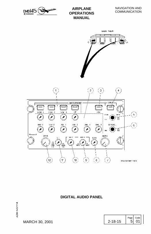
DIGITAL AUDIO PANEL
The EMB-145 is equipped with three individual Digital Audio Panels(DAP), one each for the captain, copilot and observer.
This unit allows each flight crew member to select an individualtransceiver, the intercommunication function further permittingindividual selection and audio level adjustment of the followingcommunications equipment:
• VHF communication• Crew/ramp station intercommunication• Passenger address• Reception and amplification of the NAV/COM audio signals
NORMAL MODE
In the normal mode, each flight crew member may select one COMtransceiver (VHF COM 1, VHF COM 2, VHF COM 3 or HF), theinterphone function and, simultaneously, several audio receivers (COM1, 2 and 3, HF, NAV 1 and 2, ADF 1 and 2, and DME 1 and 2).
Also, the unit may provide volume control for each radio equipment,microphone selection between Boom and Mask (Oxygen Masks), andaudio output selection between Speakers and Headphones.
Other features are the capability to filter the NDB/VOR audio signals,attenuating morse code or voice signals. Finally, Normal Mode allowsmarker beacon audio sensitivity control, which also may silencetemporarily that type of signal.
EMERGENCY MODE
The emergency mode must be selected in case of Digital Audio Panelpower loss. In this case the captain will be directly connected to theCOM 1 and NAV 1 and the copilot to the COM 2 and NAV 2.
The interphone function will also be lost.
If power is recovered the Digital Audio Panel may be returned to thenormal mode of operation by selecting another MICROPHONE button(COM 1, 2, 3 or HF).

NAVIGATION ANDCOMMUNICATION
AIRPLANEOPERATIONS
MANUAL
2-18-15 Page
2 Code
01 AUGUST 24, 2001
COMMUNICATION SYSTEM SCHEMATIC

AIRPLANEOPERATIONS
MANUAL
NAVIGATION ANDCOMMUNICATION
MARCH 30, 2001 2-18-15 Page
3 Code
01
DIGITAL AUDIO PANEL CONTROLS AND INDICATORS
1 - MICROPHONE SELECTOR BUTTONS− When pressed enables transmission and reception of radio
signals through the respective COM unit (COM 1, COM 2, COM3, HF).
− Simultaneous selection of more than one microphone selectorbutton is not possible. Pressing a different microphone selectorbutton will cause the previously selected button to bedeselected.
− A bar illuminates inside the button to indicate that it is pressed.
2 - AUDIO CONTROL KNOBS− When depressed, turns on the associated COM/NAV audio.− When rotated, provides volume control for the associated
COM/NAV audio.
3 - PASSENGER BUTTON− When pressed enables the crew to make the speech to the
passenger cabin while simultaneously deselecting the previouslyselected COM transmitter.
4 - EMERGENCY BUTTON− In case of power loss to the Digital Audio Panel, connects
microphone directly to the emergency COM mic outputs andheadphone unit to COM and NAV audio.
− The captain is connected to COM 1 and NAV 1 and the copilotto COM 2 and NAV 2. Observer radio communications capabilityis lost.
5 - BOOM/MASK BUTTON− Alternates selection between the boom (pressed) and the mask
(released) microphones.
6 - ID/VOICE BUTTON− When pressed (ID position), NDB and VOR audio signals are
filtered in order to enhance morse code identification.− When depressed (VOICE position), VOR/ILS audio signals are
filtered in order to reduce morse code signal, enhancing theVOR/ILS voice associated messages (e.g., ATIS messages).
NAVIGATION ANDCOMMUNICATION
AIRPLANEOPERATIONS
MANUAL
2-18-15 Page
4 Code
01 MARCH 30, 2001
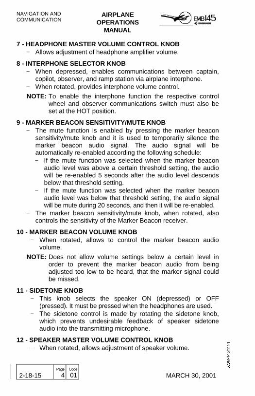
7 - HEADPHONE MASTER VOLUME CONTROL KNOB− Allows adjustment of headphone amplifier volume.
8 - INTERPHONE SELECTOR KNOB− When depressed, enables communications between captain,
copilot, observer, and ramp station via airplane interphone.− When rotated, provides interphone volume control.
NOTE: To enable the interphone function the respective controlwheel and observer communications switch must also beset at the HOT position.
9 - MARKER BEACON SENSITIVITY/MUTE KNOB− The mute function is enabled by pressing the marker beacon
sensitivity/mute knob and it is used to temporarily silence themarker beacon audio signal. The audio signal will beautomatically re-enabled according the following schedule:− If the mute function was selected when the marker beacon
audio level was above a certain threshold setting, the audiowill be re-enabled 5 seconds after the audio level descendsbelow that threshold setting.
− If the mute function was selected when the marker beaconaudio level was below that threshold setting, the audio signalwill be mute during 20 seconds, and then it will be re-enabled.
− The marker beacon sensitivity/mute knob, when rotated, alsocontrols the sensitivity of the Marker Beacon receiver.
10 - MARKER BEACON VOLUME KNOB− When rotated, allows to control the marker beacon audio
volume.
NOTE: Does not allow volume settings below a certain level inorder to prevent the marker beacon audio from beingadjusted too low to be heard, that the marker signal couldbe missed.
11 - SIDETONE KNOB− This knob selects the speaker ON (depressed) or OFF
(pressed). It must be pressed when the headphones are used.− The sidetone control is made by rotating the sidetone knob,
which prevents undesirable feedback of speaker sidetoneaudio into the transmitting microphone.
12 - SPEAKER MASTER VOLUME CONTROL KNOB− When rotated, allows adjustment of speaker volume.
AIRPLANEOPERATIONS
MANUAL
NAVIGATION ANDCOMMUNICATION
MARCH 30, 2001 2-18-15 Page
5 Code
01
DIGITAL AUDIO PANEL

NAVIGATION ANDCOMMUNICATION
AIRPLANEOPERATIONS
MANUAL
2-18-15 Page
6 Code
01 MARCH 30, 2001
THIS PAGE IS LEFT BLANK INTENTIONALLY
AIRPLANEOPERATIONS
MANUAL
NAVIGATION ANDCOMMUNICATION
REVISION 27 2-18-20 Page
1 Code
01
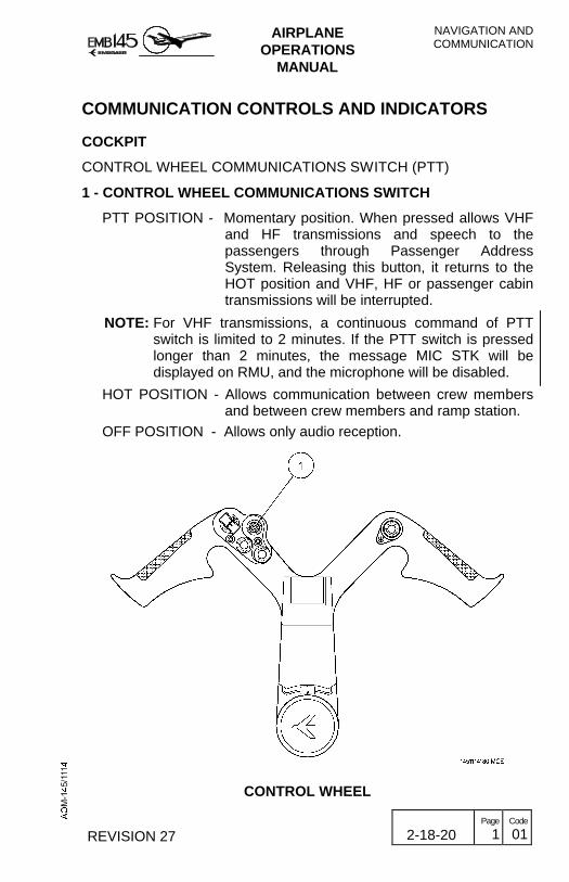
COMMUNICATION CONTROLS AND INDICATORS
COCKPIT
CONTROL WHEEL COMMUNICATIONS SWITCH (PTT)
1 - CONTROL WHEEL COMMUNICATIONS SWITCH
PTT POSITION - Momentary position. When pressed allows VHFand HF transmissions and speech to thepassengers through Passenger AddressSystem. Releasing this button, it returns to theHOT position and VHF, HF or passenger cabintransmissions will be interrupted.
NOTE: For VHF transmissions, a continuous command of PTTswitch is limited to 2 minutes. If the PTT switch is pressedlonger than 2 minutes, the message MIC STK will bedisplayed on RMU, and the microphone will be disabled.
HOT POSITION - Allows communication between crew membersand between crew members and ramp station.
OFF POSITION - Allows only audio reception.
CONTROL WHEEL

NAVIGATION ANDCOMMUNICATION
AIRPLANEOPERATIONS
MANUAL
2-18-20 Page
2 Code
01 REVISION 19
GLARESHIELD COMMUNICATION SWITCH (PTT)
1 - GLARESHIELD MIC PTT BUTTON− When pressed allows VHF and HF transmission and speech to
passengers through the Passenger Address System. Releasingthis button will interrupt transmission.
GLARESHIELD PANEL
AIRPLANEOPERATIONS
MANUAL
NAVIGATION ANDCOMMUNICATION
AUGUST 24, 2001 2-18-20 Page
3 Code
01
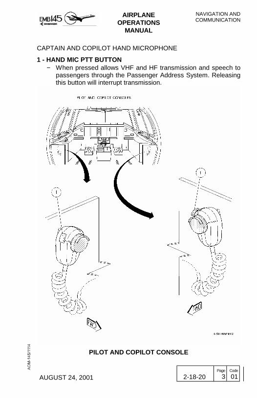
CAPTAIN AND COPILOT HAND MICROPHONE
1 - HAND MIC PTT BUTTON− When pressed allows VHF and HF transmission and speech to
passengers through the Passenger Address System. Releasingthis button will interrupt transmission.
PILOT AND COPILOT CONSOLE

NAVIGATION ANDCOMMUNICATION
AIRPLANEOPERATIONS
MANUAL
2-18-20 Page
4 Code
01 JUNE 28, 2002
CAPTAIN AND COPILOT JACK PANELS
1 - CAPTAIN AND COPILOT JACKS− Allows plugging-in the headphone, the boom microphone, and
the hand microphone.
2 - HEADSET ANR− Allows plugging-in the headphone with the Active Noise
Reduction feature.

AIRPLANEOPERATIONS
MANUAL
NAVIGATION ANDCOMMUNICATION
JUNE 28, 2002 2-18-20 Page
5 Code
01
CAPTAIN AND COPILOT JACK PANELS
NAVIGATION ANDCOMMUNICATION
AIRPLANEOPERATIONS
MANUAL
2-18-20 Page
6 Code
01 JUNE 28, 2002
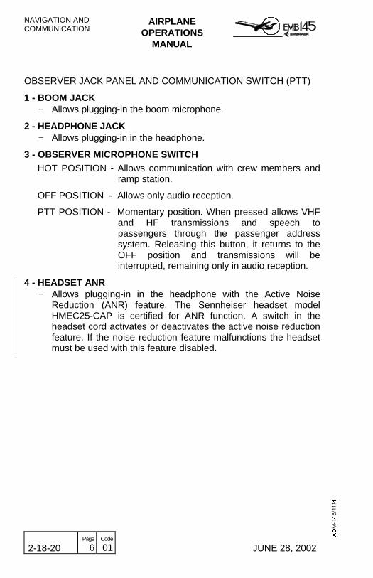
OBSERVER JACK PANEL AND COMMUNICATION SWITCH (PTT)
1 - BOOM JACK− Allows plugging-in the boom microphone.
2 - HEADPHONE JACK− Allows plugging-in in the headphone.
3 - OBSERVER MICROPHONE SWITCH
HOT POSITION - Allows communication with crew members andramp station.
OFF POSITION - Allows only audio reception.
PTT POSITION - Momentary position. When pressed allows VHFand HF transmissions and speech topassengers through the passenger addresssystem. Releasing this button, it returns to theOFF position and transmissions will beinterrupted, remaining only in audio reception.
4 - HEADSET ANR− Allows plugging-in in the headphone with the Active Noise
Reduction (ANR) feature. The Sennheiser headset modelHMEC25-CAP is certified for ANR function. A switch in theheadset cord activates or deactivates the active noise reductionfeature. If the noise reduction feature malfunctions the headsetmust be used with this feature disabled.

AIRPLANEOPERATIONS
MANUAL
NAVIGATION ANDCOMMUNICATION
JUNE 28, 2002 2-18-20 Page
7 Code
01
OBSERVER JACK PANEL
NAVIGATION ANDCOMMUNICATION
AIRPLANEOPERATIONS
MANUAL
2-18-20 Page
8 Code
01 MARCH 30, 2001
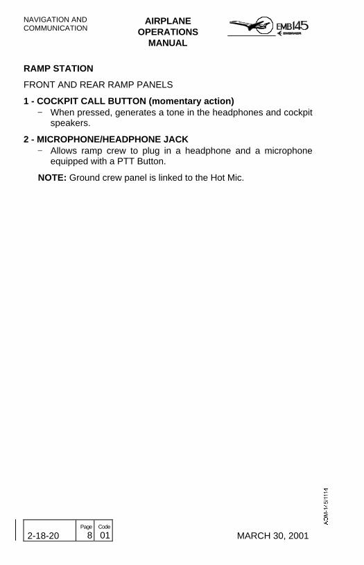
RAMP STATION
FRONT AND REAR RAMP PANELS
1 - COCKPIT CALL BUTTON (momentary action)− When pressed, generates a tone in the headphones and cockpit
speakers.
2 - MICROPHONE/HEADPHONE JACK− Allows ramp crew to plug in a headphone and a microphone
equipped with a PTT Button.
NOTE: Ground crew panel is linked to the Hot Mic.

AIRPLANEOPERATIONS
MANUAL
NAVIGATION ANDCOMMUNICATION
MARCH 30, 2001 2-18-20 Page
9 Code
01
FRONT AND REAR RAMP PANELS

NAVIGATION ANDCOMMUNICATION
AIRPLANEOPERATIONS
MANUAL
2-18-20 Page
10 Code
01 MARCH 30, 2001
THIS PAGE IS LEFT BLANK INTENTIONALLY

AIRPLANEOPERATIONS
MANUAL
NAVIGATION ANDCOMMUNICATION
JUNE 29, 2001 2-18-21 Page
1 Code
01
HF COMMUNICATION SYSTEM - HF-230
The airplane may be equipped with a HF-230 High-FrequencyCommunication System. All functions of the HF-230 System arecontrolled by the CTL-230 Control Panel located at the controlpedestal.
HF OPERATING MODES
The HF-230 High-Frequency Communications System provides thefollowing operating modes:
AMPLITUDE MODULATION
Amplitude modulation (AM) is a transmission process in which aselected frequency (called carrier frequency) and two sidebands(frequencies above and below the carrier) are generated andtransmitted. The upper sideband (USB) is the sum of the carrierfrequency and the voice, while the lower sideband (LSB) is thedifference between the two. The disadvantages of AM are that itoccupies a wide spectrum and is inefficient in the sense that a greatdeal of unneeded carrier is generated, as well as redundantinformation in the unused sideband.
SINGLE SIDEBAND
Single sideband operation achieves the same function as AM withconsiderably greater efficiency. The SSB transmitter electronicallyeliminates most or all of the carrier wave and one of the sidebands.The major advantages of SSB (either USB or LSB) as opposed to AMare greater talking power (about eight times that of AM for a givenpower input), reduced power drain, longer range and conservation ofthe spectrum (since only one sideband is required to transmit themessage).

NAVIGATION ANDCOMMUNICATION
AIRPLANEOPERATIONS
MANUAL
2-18-21 Page
2 Code
01 MARCH 30, 2001
SUPPRESSED CARRIER AND REDUCED CARRIER
The SSB operation with the carrier frequency eliminated is referred toas single sideband suppressed carrier and is designated as the TELSUP CAR mode in the HF-230.If a small portion of the carrier frequency is transmitted along with thesideband, then the operation is referred to as single sideband reducedcarrier. and is designated as the TEL PLT CAR mode in the HF-230.
SIMPLEX AND HALF-DUPLEX OPERATION
Simplex operation means that the transmission and receptionfrequencies are the same. An example of simplex operation would becommunications with a control tower using a VHF COMM transceiver.Half-duplex means transmit on one frequency and reception onanother frequency. All 176 of the ITU channels provided the HF-230are permanently programmed for half-duplex operation and willnormally be worked in the TEL SUP CAR mode. The 40 userprogrammed channels can be programmed for either simplex or half-duplex operation, and can operate in any of the available modes (AM,USB, LSB, TEL SUP CAR, or TEL PLT CAR).
NOTE: The use of LSB is legal for some international and off-shorecommunications, but is not authorized for use in the UnitedStates and most European countries.

AIRPLANEOPERATIONS
MANUAL
NAVIGATION ANDCOMMUNICATION
MARCH 30, 2001 2-18-21 Page
3 Code
01
HF NORMAL OPERATION
There are two types of operation:
- Discrete frequency tuning.
- Programmable channel.
DISCRETE FREQUENCY TUNING OPERATION
In the discrete frequency mode of operation, the user may directly tuneany one of 280,000 frequencies over the range of 2.0 to 29.9999 MHz.
1 - Access discrete frequency operation.
Apply power to the system by rotating the volume (V) knobclockwise from the OFF position.With power applied to the system, ensure that the CHAN/FREQswitch is in the FREQ position.This can be confirmed by noting that four dashes appear in theCHAN display.
2 - Enter the frequency.
Use the four frequency select knobs to enter the desired frequencyin the FREQ kHz display.
3 - Select the transmission mode.
Pull out and rotate the left inner (PULL MODE) knob in eitherdirection, to assign one of the available operating modes (USB,LSB, AM, TEL SUP CAR, or TEL PLT CAR).
4 - Tune the antenna.
Momentarily key the PTT to initiate the antenna coupler tuningcycle. A steady 1000-Hz tone will be heard in the headset orspeaker while the antenna coupler is been tuned. Approximately 1second after antenna coupler tuning cycle is completed (tuningcycle may require from 5 to 30 seconds), the 1000-Hz tone willcease, indicating that the system is ready for use on the selectedfrequency. Adjust volume (V) and squelch (S) controls as desired.
NOTE: - The discrete frequency mode always provides simplexoperation (transmit and receive frequencies are the same).

NAVIGATION ANDCOMMUNICATION
AIRPLANEOPERATIONS
MANUAL
2-18-21 Page
4 Code
01 MARCH 30, 2001
- Always key the PTT after selecting a new frequency to initiatethe antenna coupler tuning cycle. If this is not done, you mayexperience poor reception or miss important calls.
- During operation, if the receive (R) or transmit (T)annunciators on the CTL-230 flash, this indicates that thereceive or transmit (as applicable) frequency data does notmatch that being sent by the CTL-230. An equipmentmalfunction is probable and the system should be checkedby maintenance personnel.
PROGRAMMABLE CHANNEL OPERATION
In the channel mode operation, the user may select ITU and userprogrammed channels by their channel numbers. For userprogrammed channels:
1 - Access channelized operation.Apply power to system (rotate the V knob from the OFF position),and position the CHAN/FREQ switch to the CHAN position.
2 - Rotate the left outer channel select knob until user channel 1 or 40appears on the right side of the CHAN display. Use the right outerchannel select knob to select the desired channel number within theuser programmed channels.
3 - Tune the antenna.Momentarily key the PTT to initiate antenna coupler tuning cycle.Adjust volume and squelch controls, as desired.
THE 40 USER CHANNELS PROGRAMMING PROCEDURE
The 40 user programmable channels available in the HF-230 systemcan be programmed on the ground or in flight. All programmedinformation is stored in a nonvolatile memory and can be recalled byselecting the desired user channel number.
There are three types of channels that can be programmed:
1 - Half-duplexThe user programs two different frequencies, one for receive andone for transmit. The user also assigns one of the availableoperating modes (USB, LSB, AM, TEL SUP CAR, or TEL PLTCAR) to the selected channel. Half-duplex operation is availableonly when the HF-230 is being operated in the CHAN mode.

AIRPLANEOPERATIONS
MANUAL
NAVIGATION ANDCOMMUNICATION
MARCH 30, 2001 2-18-21 Page
5 Code
01
2 - Simplex
The user programs the same frequency for receive and for transmit.The user also assigns one of the available operating modes (USB,LSB, AM, TEL SUP CAR, or TEL PLT CAR) to the selectedchannel. Simplex operation is used by ARINC, ATC (Air TrafficControl), and others.
3 - Receive-only
The user programs a frequency for reception and assigns one ofthe available operating modes (USB, LSB, AM, TEL SUP CAR, orTEL PLT CAR), but does not program a transmit frequency.The transmitter and power amplifier are locked out and cannot beused when a channel has been programmed for receive-onlyoperation.
Receive-only channels are used to listen to frequency standards(W W V) for example, time, weather, Omega status, and geophysicalalert broadcasts
HALF-DUPLEX CHANNEL PROGRAMMING PROCEDURE
1 - Access channelized operation.Apply power to the system by rotating the volume (V) knobclockwise from the OFF position. With power applied to the system,ensure that the CHAN/FREQ switch is in the CHAN position.
2 - Select the desired user channel.
Rotate the left outer channel select knob in either direction untiluser channel 1 or 40 appears at the right side of the CHAN display.Then use the right outer channel select knob to select the desiredchannel number (from 1 to 40) that you wish to program.
3 - Initiate program mode.
Press the program (PGM) button once to initiate the programmingsequence. At this point, the entire display on the CTL-230 will slowlybegin to blink.
NAVIGATION ANDCOMMUNICATION
AIRPLANEOPERATIONS
MANUAL
2-18-21 Page
6 Code
01 MARCH 30, 2001
4 - Enter the receive frequency and mode of operation.
Set the desired receive frequency using the four frequency selectknobs. This procedure is identical to tuning a discrete frequencywhich has been previously described. The receive frequency willappear in the FREQ kHz display. Next, select the desired operatingmode (USB, LSB, AM, TEL SUP CAR, or TEL PLT CAR) by pullingout on the PULL MODE knob and rotating it until the appropriatemode appears in the MODE display.
5 - Store the receive frequency and mode of operation.
With the desired receive frequency and mode being displayed,press the PGM button once again to store the data. The CTL-230display will blank for a short period of time to confirm storage.
6 - Enter and store the transmit frequency.
When the display returns, it will be blinking faster with the transmitfrequency displayed (initially this is the same as the alreadyprogrammed receive frequency). At this point, you haveapproximately 20 seconds to begin entering the desired transmitfrequency. If no changes are made during the next 20 seconds, thecurrently displayed transmit frequency will become invalid and youwill have created a receive-only channel. Set the desired transmitfrequency using the four frequency select knobs. This procedure isidentical to entering the receive described above. With the desiredtransmit frequency shown in the FREQ kHz display, press the PGMbutton once again to store the data.As before, the CTL-230 display will blank for a short period of timeto confirm storage. The display will then return to normal with thenew channel data (channel number, mode, and receive frequency)showing.
7 - Tune the antenna.
Momentarily key the PTT to initiate the antenna coupler tuningcycle. Adjust the volume (V) and squelch (S) controls, as desired.
NOTE: If additional user channels are to be programmed, repeatsteps 2 through 6 at this time. Ensure that you make andkeep for reference a list of channel numbers, and thereceive and transmit frequencies, as well as the mode ofoperation that are programmed on the individual channels.

AIRPLANEOPERATIONS
MANUAL
NAVIGATION ANDCOMMUNICATION
MARCH 30, 2001 2-18-21 Page
7 Code
01
SIMPLEX CHANNEL PROGRAMMING PROCEDURE
When you program a channel for simplex operation, both the receiveand the transmit frequencies will be the same. Programming a simplexchannel is similar to programming a half-duplex channel, except thePGM button is pressed twice after the receive frequency and mode ofoperation are entered to store the frequency in both the receive andthe transmit positions.
RECEIVE-ONLY CHANNEL PROGRAMMING PROCEDURE
When you program a channel for receive-only operation, only a receivefrequency is entered and stored. Programming a receive-only channelis similar to programming a simplex channel except the PGM button ispressed only once after the receive frequency and mode of operationare entered. The programming sequence is then terminated withoutentering a transmit frequency.
Program sequence can be terminated in any one of the three ways:− By momentarily keying the PTT.− By positioning the CHAN/FREQ switch to FREQ and then back to
CHAN.− By waiting for the 20-second timer to run out (this is the preferred
method).
THE 176 ITU CORRESPONDENCE CHANNELS OPERATION
The 176 ITU (International Telecommunication Union) publiccorrespondence channels (and their receive and transmit frequencies)in the maritime radiotelephone network are permanently programmedin the nonvolatile memory of the CTL-230 Control. The 176 ITUchannels all operate half-duplex in TEL SUP CAR (preferred) or TELPLT CAR modes only.
Perform the following steps to operate on the ITU channels:
1 - Access channelized operation.
Apply power to the system by rotating the volume (V) knobclockwise from the OFF position.With power applied to the system, ensure that the CHAN/FREQswitch is in the CHAN position.

NAVIGATION ANDCOMMUNICATION
AIRPLANEOPERATIONS
MANUAL
2-18-21 Page
8 Code
01 MARCH 30, 2001
2 - Select the desired ITU channel.
Rotate the left outer channel select knob in either direction until thedesired ITU band appears in the one or two left-hand digits in theCHAN display. Next use the right outer channel select knob toselect the individual channel number within the ITU band (the tworight-hand digits in the CHAN display.When the ITU channel numbers have been entered, the airplanereceive frequency will appear in the FREQ kHz display and the Rannunciator will be illuminated.
NOTE: Refer to a list of the ITU maritime radiotelephone channelsto see that the above incrementing and decrementingchanges are consistent with the actual ITU channelnumbers.
3 - Select the operating mode.
Pull out and rotate the left inner (PULL MODE) knob in eitherdirection to select between TEL SUP CAR or TEL PLT CAR mode.When the mode has been selected, push the knob back in.
4 - Tune the antenna.
Momentarily key the PTT to initiate the antenna coupler tuningcycle. A steady 1000-Hz tone will be heard in the headset orspeaker while the antenna coupler is tuning. Approximately1-second after completion of the antenna coupler tuning cycle(tuning cycle may require from 5 to 30 seconds), the 1000-Hz tonewill cease, indicating that the system is ready for use on theselected ITU channel. Adjust volume (V) and squelch (S) controlsas desired.When transmitting, the receive frequency and R annunciator in theFREQ kHz display are replaced with the aircraft transmit frequencyand a T annunciator.
FAULT INDICATION
If the antenna coupler does not tune after approximately 35 to 40seconds, the steady 1000-Hz tone will begin to beep, indicating a faulthas occurred. To clear the fault, simply rotate one of theFrequency/Channel Select Knobs away from and then back to thedesired frequency or channel and initiate another tuning cycle bymomentarily pressing the PTT button. The 1000-Hz tone should againbe heard and then disappear at the end of the tuning cycle. If thebeeping recurs, try the clearing procedure a second time. If a fault isstill indicated, there is probably an equipment malfunction.

AIRPLANEOPERATIONS
MANUAL
NAVIGATION ANDCOMMUNICATION
MARCH 30, 2001 2-18-21 Page
9 Code
01
HF CONTROLS AND INDICATORS
CTL-230 CONTROL PANEL
1 - GAS DISCHARGE DISPLAY
− Shows channel number (CHAN), mode of operation (MODE),transmit and receive frequency in kilohertz, and separate R(receive) and T (transmit) annunciators.
2 - CHANNEL FREQUENCY SELECT KNOBS
− Knob functions when selecting a discrete frequency
FREQUENCYSELECT KNOB KNOB FUNCTION
Left outer Selects the MHz digits (2 through29) in the FREQ kHz display.
Left inner (pushed in) Selects the 100-kHz digit (0 through9) in the FREQ kHz display.
Left inner (pulled out) Rotate to select USB, AM, LSBmodes.
Right outer Selects the 10-kHz digit (0 through9) in the FREQ kHz display.
Right inner (pushed in) Selects the 1-kHz digit (0 through 9)in the FREQ kHz display.
Right inner (pulled out) Selects the 100-Hz digit (0 through 9)in the FREQ kHz display.
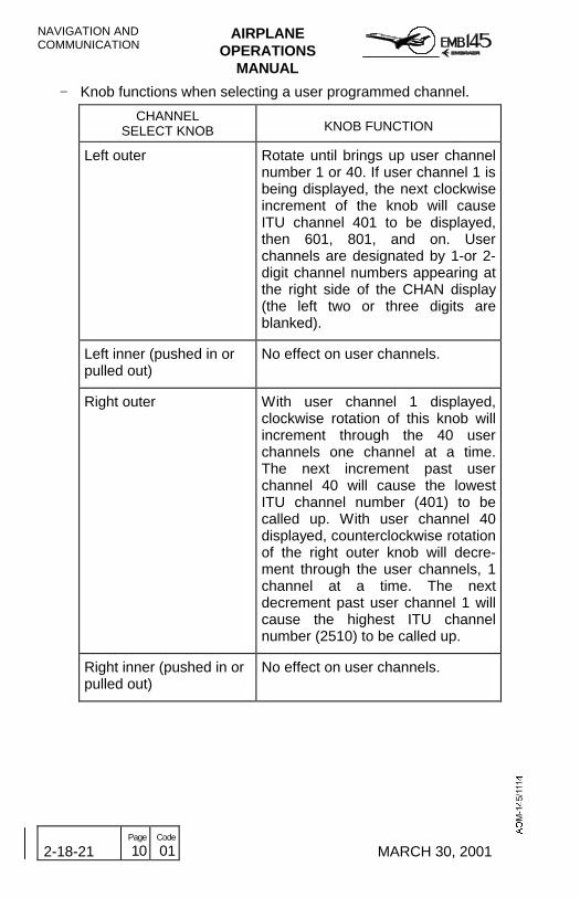
NAVIGATION ANDCOMMUNICATION
AIRPLANEOPERATIONS
MANUAL
2-18-21 Page
10 Code
01 MARCH 30, 2001
− Knob functions when selecting a user programmed channel.
CHANNELSELECT KNOB KNOB FUNCTION
Left outer Rotate until brings up user channelnumber 1 or 40. If user channel 1 isbeing displayed, the next clockwiseincrement of the knob will causeITU channel 401 to be displayed,then 601, 801, and on. Userchannels are designated by 1-or 2-digit channel numbers appearing atthe right side of the CHAN display(the left two or three digits areblanked).
Left inner (pushed in orpulled out)
No effect on user channels.
Right outer With user channel 1 displayed,clockwise rotation of this knob willincrement through the 40 userchannels one channel at a time.The next increment past userchannel 40 will cause the lowestITU channel number (401) to becalled up. With user channel 40displayed, counterclockwise rotationof the right outer knob will decre-ment through the user channels, 1channel at a time. The nextdecrement past user channel 1 willcause the highest ITU channelnumber (2510) to be called up.
Right inner (pushed in orpulled out)
No effect on user channels.

AIRPLANEOPERATIONS
MANUAL
NAVIGATION ANDCOMMUNICATION
MARCH 30, 2001 2-18-21 Page
11 Code
01
− Knob functions when selecting an ITU telephone channel
CHANNELSELECT KNOB KNOB FUNCTION
Left outer This knob is used to select the ITUband (the one or two left-hand digitsin the CHAN display). Clockwiserotation of the knob increments theCHAN display to the next higherITU band and counterclockwiserotation decrements to the nextlower ITU band. If ITU channel 401is being displayed, the nextclockwise increment of the knob willcause ITU channel 601 to bedisplayed, then 801, 1201, 1601,and 2201. Rollover occurs betweenthe top ITU band (22 MHz) and userprogrammed channel number 1,and between the lowest ITU band(4 MHz) and user programmedchannel number 40.
Left inner (pushed in) No effect on ITU channels.
Left inner (pulled out) Rotate to select between TEL SUPCAR and TEL PLT CAR models.
Right outer This knob selects the individualchannel number within the ITUband (the two right-hand digits inthe CHAN display). If the channelnumber is incremented beyond thehighest channel for that band, thelowest channel for the next higherband will appear.For example, if ITU channel 427 isbeing displayed, the next clockwiseincrement of the knob will causeITU channel 601 to be displayed.Likewise, decrementing below thelowest channel in a band will selectthe highest channel in the nextlower band.
Right inner (pushed in orpulled out)
No effect on ITU channels

NAVIGATION ANDCOMMUNICATION
AIRPLANEOPERATIONS
MANUAL
2-18-21 Page
12 Code
01 MARCH 30, 2001
3 - PROGRAM BUTTON
− Allows the user to store frequencies in the 40 user programmedchannels (refer to Programmable Channel Operation section forproper operation).
4 - CHANNEL/FREQUENCY SWITCH
− The channel/frequency select knobs are used to select thedesired user channel or ITU telephone channel number(CHAN/FREQ switch positioned to CHAN) or the proper transmitand receive frequencies when operating in the discretefrequency mode number (CHAN/FREQ switch positioned toFREQ). The knobs are also used to enter frequencies whenprogramming the user channels number (CHAN/FREQ switchpositioned to CHAN).
5 - SQUELCH/TEST CONTROL
− This knob is adjusted to mute undesired background noise. Thenoise proper setting is made by rotating the S (squelch) knobclockwise from TST (test) position until background noise canbe heard and by turning it counterclockwise until the backgroundnoise disappears or is just barely audible.
− When the S knob is in the TST position, the squelch circuit is, ineffect, removed from the receiver audio circuit in the TST,maximum background noise (depending on the volume controlsetting) will be heard.
− Setting the squelch control too far clockwise can result inblocking out weak signals. There are times when it will benecessary to leave the squelch control in the TST position tomaintain satisfactory reception. This is because of conditionsrelating to propagation and the ionosphere that causes the HFreceiver to operate with a signal that is subject to considerablefading and which is marginally strong.

AIRPLANEOPERATIONS
MANUAL
NAVIGATION ANDCOMMUNICATION
MARCH 30, 2001 2-18-21 Page
13 Code
01
6 - OFF/ CLARIFIER CONTROL
− Concentric with the volume knob, and sharing the same OFFposition, the CLAR knob is used when receiving SSB signalsthat may be slightly off frequency.
− The CLAR knob can help eliminate unnatural sounds whenreceiving USB, LSB, or either of the telephone modes.
− The clarifier function does not affect AM reception, and isdisabled during transmit or when the CLAR knob is set to OFFposition.
− To operate the clarifier, rotate the CLAR knob clockwise from offuntil the centering dot is visible on the knob skirt at the midrotation point. This is the neutral or zero shift position. From thisposition, the CLAR knob is adjusted clockwise orcounterclockwise for the best clarity or the most natural sound ofthe signal being received.
NOTE: When the audio quality of the received SSB signal is goodand natural sounding, the CLAR knob should remain in theOFF position.
7. OFF/VOLUME CONTROL
− Turns system off and on and controls volume. Rotating the Vknob clockwise from the OFF position turns the system on.Continued clockwise rotation increases audio level. When thesystem is turned OFF, the discrete frequency or channel, andmode of operation displayed on the CTL-230 will be stored innonvolatile memory and will be restored to the display the nexttime the system is turned on.
NOTE: It is recommended that the HF-230 system be turned onat least 15 minutes before use, to ensure frequencystability under varying environmental conditions.

NAVIGATION ANDCOMMUNICATION
AIRPLANEOPERATIONS
MANUAL
2-18-21 Page
14 Code
01 MARCH 30, 2001
THIS PAGE IS LEFT BLANK INTENTIONALLY

AIRPLANEOPERATIONS
MANUAL
NAVIGATION ANDCOMMUNICATION
MARCH 30, 2001 2-18-21 Page
15 Code
01
CTL-230 HF CONTROL PANEL

NAVIGATION ANDCOMMUNICATION
AIRPLANEOPERATIONS
MANUAL
2-18-21 Page
16 Code
01 MARCH 30, 2001
THIS PAGE IS LEFT BLANK INTENTIONALLY

AIRPLANEOPERATIONS
MANUAL
NAVIGATION ANDCOMMUNICATION
MARCH 30, 2001 2-18-22 Page
1 Code
01
THIRD VHF COMMUNICATIONS SYSTEMThe airplane may be equipped with a third VHF CommunicationsSystem. All functions of the Collins VHF-22A System are controlled bythe CTL-22 VHF Control Panel located at the main panel.
The Avionics Master DC Bus 1 supplies the third VHFCommunications System with a protective 5A circuit breaker.
THIRD VHF COM CONTROLS AND INDICATORS
1 - ACTIVE FREQUENCY DISPLAY− Displays the active frequency (frequency to which the equipment
is tuned) and diagnostics messages.
2 - XFR/MEM SWITCH− This is a 3-position, spring-loaded toggle switch.− When held to the XFR position, the preset frequency is
transferred up to the active display and the equipment retunes.The previously active frequency becomes the new presetfrequency and is displayed in the lower window.
− When held to the MEM position, one of the six stacked memoryfrequencies is loaded into the preset display.
− Successive pushes cycle the six memory frequencies throughthe display.
3 - FREQUENCY SELECT KNOBS− Two concentric knobs control the preset or active frequency
displays.− The large knob changes the digits to the left of the decimal point
in 1 MHz steps.− The smaller knob changes the digits to the right of the decimal
point in 0.005 MHz steps.− Numbers roll over at the upper and lower frequency limits.

NAVIGATION ANDCOMMUNICATION
AIRPLANEOPERATIONS
MANUAL
2-18-22 Page
2 Code
01 MARCH 30, 2001
4 - ACTIVE BUTTON− Push the ACT button for about 2 seconds to enable the
frequency select knobs to directly retune the VHF-22A (activefrequency).
− The bottom window will display dashes and the upper windowwill continue to display the active frequency.
− Push the ACT button a second time to return the control to thenormal 2-display mode.
5 - TEST BUTTON− The self-test diagnostic routine is initiated in the transceiver by
pushing the TEST button.− The active and preset display intensity will flash, modulating its
brightness from minimum to maximum indicating self-test inprogress.
− The active frequency display will show four dashes and thepreset frequency display will show “00”.
− An audio tone will be heard from the audio system.− At the completion of the self-test program, the display will return
to its normal operation if no problem occurs.− In case of a detected failure, “diAG” (diagnostic) letters will be
displayed in the active and a 2-digit diagnostic code will bedisplayed in the preset display.
− Record any diagnostic codes displayed to help maintenancepersonnel in locating the problem.
6 - STORE BUTTON− The STO button allows up to six preset frequencies to be
selected and entered into the controls non-volatile memory.− After presetting the frequency to be stored, push the STO
button. The upper window displays the channel number ofavailable memory (CH1 through CH6); the lower windowcontinues to display the frequency to be stored. Forapproximately 5 seconds, the MEM switch may be used toadvance through channel numbers without changing the presetdisplay. Push the STO button a second time to commit thepreset frequency to memory in the selected location. Afterapproximately 5 seconds, the control will return to normaloperation.
AIRPLANEOPERATIONS
MANUAL
NAVIGATION ANDCOMMUNICATION
MARCH 30, 2001 2-18-22 Page
3 Code
01
7 - POWER AND MODE KNOBOFF - Turns off the system.ON - Turns on the system.SQ OFF - Disables the receiver squelch circuits. Use this position
to set volume control or, if necessary, to try to receive avery weak signal that cannot operate the squelchcircuits.
8 - ANNUNCIATORS− The COM control contains MEM (memory) and TX (transmit)
annunciators.− The MEM annunciator illuminates whenever a preset frequency
is being displayed in the lower window.− The TX annunciator illuminates whenever the VHF-22A is
transmitting.
9 - PRESET FREQUENCY DISPLAY− Displays the preset (inactive) frequency and diagnostics
messages.− The frequencies displayed on the COM control show only five of
the six digits.
10 - COMPARE ANNUNCIATOR− ACT momentarily illuminates when active and preset
frequencies are being switched.− ACT flashes if the actual radio frequency is not identical to the
frequency shown in the active frequency display.

NAVIGATION ANDCOMMUNICATION
AIRPLANEOPERATIONS
MANUAL
2-18-22 Page
4 Code
01 MARCH 30, 2001
THIS PAGE IS LEFT BLANK INTENTIONALLY

AIRPLANEOPERATIONS
MANUAL
NAVIGATION ANDCOMMUNICATION
AUGUST 24, 2001 2-18-22 Page
5 Code
01
CTL-22 VHF CONTROL PANEL

NAVIGATION ANDCOMMUNICATION
AIRPLANEOPERATIONS
MANUAL
2-18-22 Page
6 Code
01 MARCH 30, 2001
THIS PAGE IS LEFT BLANK INTENTIONALLY
AIRPLANEOPERATIONS
MANUAL
NAVIGATION ANDCOMMUNICATION
MARCH 30, 2001 2-18-23 Page
1 Code
01
SELCAL SYSTEMThe Ground-to-Air Selective Calling (SELCAL) System operates inconjunction with the communication radios. The SELCAL providescontinuous monitoring of a pre-set frequency, eliminating the need tocontinuously monitor the communication frequencies by the flight crew.
The SELCAL permits ground stations, equipped with encodingequipment, to call individual airplane by transmitting a coded signal.This coded signal will activate only one SELCAL unit to respond to thatparticular coded signal. In this case, a SELCAL voice message isactivated through the Aural Warning Unit. Once activated, the systemis reset for further monitoring by pressing the SELCAL Button, locatedon the Main Panel, or actuating the PTT function (on Control Wheel orglareshield panel).
NOTE: - For some airplanes the SELCAL enables only the VHF 2operation or only the HF operation.
- SELCAL will recognize the coded signal from ground stationsonly if the associated system (HF or VHF2) is powered onand its frequency is adjusted to the ground station frequency.
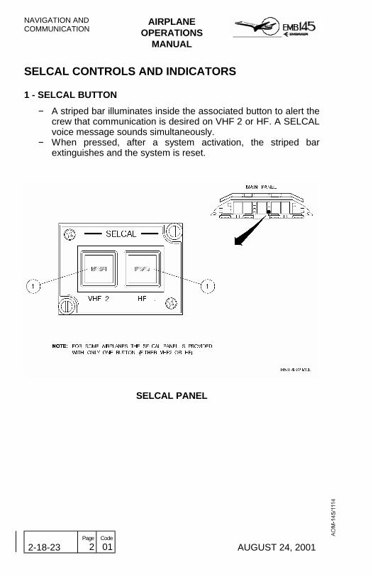
NAVIGATION ANDCOMMUNICATION
AIRPLANEOPERATIONS
MANUAL
2-18-23 Page
2 Code
01 AUGUST 24, 2001
SELCAL CONTROLS AND INDICATORS
1 - SELCAL BUTTON
− A striped bar illuminates inside the associated button to alert thecrew that communication is desired on VHF 2 or HF. A SELCALvoice message sounds simultaneously.
− When pressed, after a system activation, the striped barextinguishes and the system is reset.
SELCAL PANEL
AIRPLANEOPERATIONS
MANUAL
NAVIGATION ANDCOMMUNICATION
REVISION 29 2-18-25 Page
1 Code
01
COCKPIT VOICE RECORDERThe Solid State Cockpit Voice Recorder System records all audiosignals transmitted and received by the crew members via the DigitalAudio Panels, and any audible noise in the cockpit, through an areamicrophone installed below the standby compass.
The CVR is in operation whenever the essential DC Bus 2 isenergized, storing the last 2 hours of recorded information in a solidstate crash survivable memory unit. Any data older than 2 hours isautomatically overwritten by the most recent audio inputs.
A crash impact switch cuts off power to the CVR immediately afterexperiencing a 5 G impact in order to preserve the recorded data.
The CVR also incorporates an Underwater Locator Beacon (ULB).Powered by a dedicated battery, the ULB starts transmitting anacoustic signal in the 37.5 kHz frequency once it senses contact withwater, thus easing wreckage site location of a submerged airplane.The signal is transmitted during approximately 30 days.
A signal from the captain’s clock allows timing correlation betweenCVR and FDRS.
SELF TEST
When the TEST button is pressed the unit performs a functionalself-test to verify the integrity of the system. A successful self-testresults in a one-second activation of the status LED on the controlpanel and a two-second tone (800 Hz for Honeywell equipment and620 to 660 Hz for L3 equipment) that may be heard from a headphoneplugged to the CVR control panel jack. If a failure is detected duringthe test, the status LED will not be activated and the aural tone will notbe heard.

NAVIGATION ANDCOMMUNICATION
AIRPLANEOPERATIONS
MANUAL
2-18-25 Page
2 Code
01 REVISION 29
ERASE FUNCTION
Previously recorded CVR data may be made unavailable if the ERASEbutton on the CVR control panel is pressed, provided the airplane is onthe ground and with the parking brake applied. In this case, only theCVR manufacturer (for Honeywell equipment) will be able to recoverthe “erased” data.
When the ERASE button is pressed (for 2 seconds for L3 equipment),a two-second 400 Hz tone may be heard from a headphone plugged tothe CVR control panel jack, confirming that the erase command wassuccessful.
COCKPIT VOICE RECORDER CONTROLS ANDINDICATORS
1 - ERASE BUTTON− Erases previously recorded data from the crash survivable
memory.− Function is available only on the ground, with the parking brake
applied.
2 - TEST BUTTON− Tests system integrity.− A successful self-test results in a one second activation of the
status LED.− In case of failure, the status LED on the control panel is not
activated.
3 - HEADPHONE JACK− Allows plugging a headphone to monitor the test tone, the erase
tone and recorded audio signals.
4 - STATUS LED− Illuminates during one second to indicate a successful test.

AIRPLANEOPERATIONS
MANUAL
NAVIGATION ANDCOMMUNICATION
REVISION 29 2-18-25 Page
3 Code
01
HONEYWELL COCKPIT VOICE RECORDER PANEL

NAVIGATION ANDCOMMUNICATION
AIRPLANEOPERATIONS
MANUAL
2-18-25 Page
4 Code
01 REVISION 29
L3 COCKPIT VOICE RECORDER PANEL
AIRPLANEOPERATIONS
MANUAL
NAVIGATION ANDCOMMUNICATION
REVISION 17 2-18-27 Page
1 Code
01
PASSENGER ADDRESS SYSTEMThe Passenger Address System (PAS) provides communicationbetween cockpit and flight attendants, and announcements fromcockpit or flight attendants to the passenger cabin.
The PAS also interfaces with the audio entertainment and prerecordedannouncement systems to provide music and safety briefing/flightinformation through the passenger loudspeakers.
The following functions are available through the PAS:
− Voice announcement transmission (speech) to the PAX cabin.− Call function from captain, copilot and observer to flight attendant
and vice-versa through chime tone.− Call function from passenger to attendant, through chime tone.− Chime tone for NO SMOKING and FASTEN SEAT BELTS signals.− Interface to boarding music and passenger briefing.
The PAS component responsible for sending/receiving signals to/fromcockpit, attendant handsets, and for passenger entertainment andprerecorded announcement systems is the Passenger AddressAmplifier (PAA), located in the airplane electronic compartment.
The PAA establishes the priority among the input signals from theseveral sources and then drives these signals to the proper cabinloudspeakers. The PAA also provides the logic for generation of theaural and visual annunciators, chimes for attendant, passenger andcockpit calls, and for NO SMOKING and FASTEN SEAT BELTSsignals.

NAVIGATION ANDCOMMUNICATION
AIRPLANEOPERATIONS
MANUAL
2-18-27 Page
2 Code
01 REVISION 30
PASSENGER ADDRESS OPERATING MODES
MUTED MODE
The Muted Mode is automatically selected during power up and whenno other mode is selected. In this mode there will be no chimes, nolights and no microphones enabled during power up or power supplytransients.
PILOT-TO-PASSENGER MODE
The Pilot-to-Passenger Mode is enabled by pressing the PassengerButton, labeled PAX, on the Digital Audio Panel. When this mode isenabled the captain, copilot or observer may transmit announcementsto the passengers, by pressing the respective PTT. The priority of thetransmission through the system is the following: captain, copilot,observer. There are no chimes in this mode.
ATTENDANT-TO-PASSENGER MODE
The Attendant-to-Passenger Mode is enabled by pressing the PAButton in the Attendant Handset. When this mode is enabled the flightattendant may transmit announcements to the passengers, by pressingthe Attendant Handset PTT. If the PAX Button is selected on the DigitalAudio Panel in the cockpit, besides listening the attendantannouncements in the cockpit speaker or headphones, the pilots andobserver take priority over the attendant announcements.
Some airplanes have a knob installed in the main panel or in thecontrol pedestal which allows to adjust the volume of the PAannouncements in the flight deck.

AIRPLANEOPERATIONS
MANUAL
NAVIGATION ANDCOMMUNICATION
MARCH 30, 2001 2-18-27 Page
3 Code
01
THIS PAGE S LEFT BLANK INTENTIONALLY

NAVIGATION ANDCOMMUNICATION
AIRPLANEOPERATIONS
MANUAL
2-18-27 Page
4 Code
01 MARCH 30, 2001
PASSENGER ADDRESS CONTROLS AND INDICATORS
INTERPHONE CONTROL UNIT
1 - CABIN BUTTON− Allows interphone communication between pilots and flight
attendant.− Generates a “ding-dong” chime through the Passenger Address
Amplifier and illuminates the PILOT light on the Attendant’s CallPanel.
− A striped bar illuminates inside the button to indicate that it ispressed.
2 - CABIN EMERGENCY BUTTON− Provides the same functions as the Cabin Button, except that it
illuminates the Pilot Emergency Light, labeled EMER PILOT, onthe Attendant’s Call Panel.
− A striped bar illuminates inside the button to indicate that it ispressed.
3 - BACKUP INTERPHONE BUTTON− Allows interphone communication between pilots and attendant,
in case of normal mode failure.− Illuminates CABIN and CAB EMERG buttons on the ICU, and
PILOT and EMERG PILOT annunciators on the Attendant’s CallPanel.
− A striped bar illuminates inside the button to indicate that ispressed.
4 - FLIGHT ATTENDANT CALL BUTTON− Generates a chime in the passenger address, to call a flight
attendant.− During backup operation generates a tone in the chime located
in the passenger cabin ceiling, near the emergency exits.

AIRPLANEOPERATIONS
MANUAL
NAVIGATION ANDCOMMUNICATION
AUGUST 24, 2001 2-18-27 Page
5 Code
01
INTERPHONE CONTROL UNIT
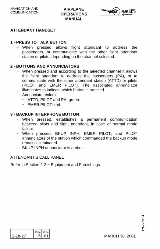
NAVIGATION ANDCOMMUNICATION
AIRPLANEOPERATIONS
MANUAL
2-18-27 Page
6 Code
01 MARCH 30, 2001
ATTENDANT HANDSET
1 - PRESS TO TALK BUTTON− When pressed allows flight attendant to address the
passengers, or communicate with the other flight attendantstation or pilots, depending on the channel selected.
2 - BUTTONS AND ANNUNCIATORS− When pressed and according to the selected channel it allows
the flight attendant to address the passengers (PA), or tocommunicate with the other attendant station (ATTD) or pilots(PILOT and EMER PILOT). The associated annunciatorilluminates to indicate which button is pressed.
− Annunciator colors:− ATTD, PILOT and PA: green.− EMER PILOT: red.
3 - BACKUP INTERPHONE BUTTON− When pressed, establishes a permanent communication
between pilots and flight attendant, in case of normal modefailure.
− When pressed, BKUP INPH, EMER PILOT, and PILOTannunciators of the station which commanded the backup moderemains illuminated.
− BKUP INPH annunciator is amber.
ATTENDANT’S CALL PANEL
Refer to Section 2-2 − Equipment and Furnishings.

AIRPLANEOPERATIONS
MANUAL
NAVIGATION ANDCOMMUNICATION
AUGUST 24, 2001 2-18-27 Page
7 Code
01
ATTENDANT HANDSET

NAVIGATION ANDCOMMUNICATION
AIRPLANEOPERATIONS
MANUAL
2-18-27 Page
8 Code
01 MARCH 30, 2001
THIS PAGE IS LEFT BLANK INTENTIONALLY

AIRPLANEOPERATIONS
MANUAL
NAVIGATION ANDCOMMUNICATION
MARCH 30, 2001 2-18-30 Page
1 Code
01
ATTITUDE AND HEADING REFERENCE SYSTEM(AHRS)On EMB-145/135 airplanes, the equipment responsible for generatingattitude and heading data is the Attitude and Heading ReferenceSystem (AHRS). Optionally the AHRS may be replaced by the InertialReference System (IRS) that, aside generating attitude and headingdata, may still provide position information to the Flight ManagementSystem (FMS).
There are two types of AHRS installed on EMB-145/135 airplanes: theAH-800 and the AH-900.
Regardless of version, the airplane is equipped with two identical andindependent units, identified as AHRS 1 and AHRS 2.
The interface of the AHRS with other systems and equipment of theairplane is the following:
− Air Data Computers (ADC 1 and ADC 2): The AHRS 1 and AHRS 2receive true airspeed information from the ADC 1 and ADC 2respectively, to improve the precision of the computed navigationdata.
− Integrated Computers (IC1 and IC2): The AHRS 1 and AHRS 2provide pitch, roll and heading information to the respective PFD,and heading information to the respective MFD, through the IC-600s.Data is transmitted separately to both sides, to ensure that single ICfailure does not compromise the data path.
− Radio Management Units (RMU 1 and RMU 2): The AHRS 1provides heading information to both RMUs via DAU 2.
− Autopilot System: The AHRS 1 provides pitch, roll and accelerationinformation to the Autopilot System via IC-600-1.
− Weather Radar: The AHRS 2 provides attitude information to theWeather Radar for antenna stabilization.
− Flight Management System (FMS): The AHRS provides attitude andheading information to the FMS.
− EGPWS/GPWS: The AHRS 1 provides attitude and headinginformation to the EGPWS/GPWS.
NAVIGATION ANDCOMMUNICATION
AIRPLANEOPERATIONS
MANUAL
2-18-30 Page
2 Code
01 MARCH 30, 2001
− Stall Protection System (SPS): The AHRS provides attitude ratevariation and vertical acceleration information to the SPS.
− Integrated Standby Instrument System (ISIS): the AHRS 1 providesheading information to the ISIS.
− Windshear Detection And Escape Guidance System: The AHRS 1provides attitude rate variation and vertical acceleration informationto the windshear computer.
− Flight Data Recorder (FDR): The AHRS 1 provides attitude andheading information to the FDR via DAU 2 and IC-600.

AIRPLANEOPERATIONS
MANUAL
NAVIGATION ANDCOMMUNICATION
MARCH 30, 2001 2-18-30 Page
3 Code
01
AHRS SCHEMATIC
NAVIGATION ANDCOMMUNICATION
AIRPLANEOPERATIONS
MANUAL
2-18-30 Page
4 Code
01 DECEMBER 20, 2002
AH-800 AHRS VERSION
Each AH-800 AHRS consists of an Attitude and Heading Computer(AHC), a Magnetic Flux Detector Unit (MFDU), a Memory Module andan AHRS Control Panel.
Each AHC uses two 28 VDC power inputs, one for normal power(primary source) and other for backup power (airplane batteries). TheAHC 1 primary power source is the Essential DC Bus 1 and its backuppower source is the Backup Essential Bus. The AHC 2 primary powersource is the DC Bus 2 and its backup power source is the BackupBus 2. If the AHC loses the primary power, it automatically transfers tobackup power.
When the AHC operates solely on backup power, it will operate for 40minutes.
ATTITUDE AND HEADING COMPUTER (AHC)
The major component of the AHRS is the AHC. The AHC containsthree single axis interferometer fiber optic gyros (IFOG) mounted alongthe principal axis of the unit to measure the airplane angular motion.The signals processed and generated by the IFOGs as well as theinformation of attitude, heading and airplane axis accelerations aretransmitted by the AHC in digital format to the airplane systems andequipment interfaced with the AHRS. In addition, the AHC providesexcitation, current feedback control and signal demodulation interfacesto the flux detector.
MAGNETIC FLUX DETECTOR UNIT (MFDU)
The AHRS uses the wing tip mounted MFDU as long term magneticreference. The flux detector senses the horizontal component of theearth magnetic field and provides continuous magnetic headingreference to the AHC. The heading reference is processed by the AHCto compute an inertial stabilized magnetic heading output.
MEMORY MODULE
The memory module is used to store the AHC mounting tray alignmentcoefficients, flux valve compensation coefficients and discrete data(orientation, source/destination identifier and interface digital buses).
AHRS CONTROL PANEL
The AHRS control panel allows canceling the magnetic field distortionas well as selecting the Directional Gyro (DG) or Slaved (SLVD)Modes.

AIRPLANEOPERATIONS
MANUAL
NAVIGATION ANDCOMMUNICATION
MARCH 30, 2001 2-18-30 Page
5 Code
01
AH-800 OPERATING MODES
The AHRS has six fundamental operating modes, which are describedbelow.
− Initialization mode: The Initialization Mode is entered upon powerup of the system. During the operation in this mode the AHRSperforms self-tests to determine the condition of its components(sensors, AHC, power supply, etc). Furthermore the AHRS performsa first order leveling process to determine pitch and roll, and furtherslaves the magnetic heading to the flux valve. At the end of theInitialization Mode the system enters the Full Performance Mode,unless the crew selects the DG Mode or the system detects a lack ofinput, in this case reverting automatically to the Basic Mode.
− Full Performance Mode: The Full Performance Mode (slaved) isthe standard system operating configuration. When operating in thismode, the TAS input from the ADC is used in the vertical channel(pitch and roll) to produce a Schuler tuned erection loop for pitch androll attitude, and the flux valve is used as a continuous headingreference.
NOTE: When switched from DG to SLVD (Full Performance Mode)the system performs automatic synchronization to the fluxvalve.
− DG Mode: The DG Mode, which causes the heading channel tooperate as a free non-slaved gyro, is selected by the flight crew andis used when operating in charted areas of unreliable magneticheading or in case of a failure in the flux valve.
− Basic Mode: The Basic Mode is entered automatically by the systemif the TAS becomes invalid. AHRS attitude output in this mode iscorrected by a simple first-order erection loop similar to that of aconventional vertical gyro.
− Test Mode: The Test Mode is to be operated mainly by the groundpersonnel during maintenance procedures. This mode is activatedthrough a switch located in the maintenance panel behind the pilotseat when the airplane is on the ground. During the test, the systemverifies the outputs for proper operation of the data channels,interconnections and indications.
− Maintenance Mode: The Maintenance Mode is used formaintenance purposes only.
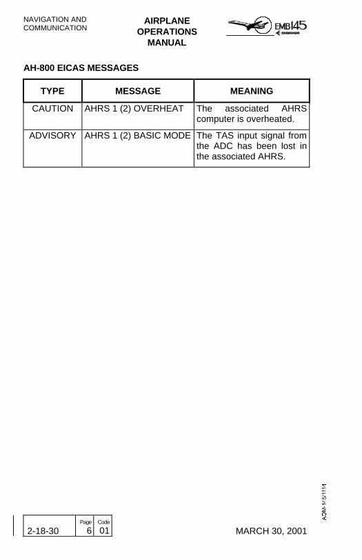
NAVIGATION ANDCOMMUNICATION
AIRPLANEOPERATIONS
MANUAL
2-18-30 Page
6 Code
01 MARCH 30, 2001
AH-800 EICAS MESSAGES
TYPE MESSAGE MEANING
CAUTION AHRS 1 (2) OVERHEAT The associated AHRScomputer is overheated.
ADVISORY AHRS 1 (2) BASIC MODE The TAS input signal fromthe ADC has been lost inthe associated AHRS.

AIRPLANEOPERATIONS
MANUAL
NAVIGATION ANDCOMMUNICATION
MARCH 30, 2001 2-18-30 Page
7 Code
01
THIS PAGE IS LEFT BLANK INTENTIONALLY

NAVIGATION ANDCOMMUNICATION
AIRPLANEOPERATIONS
MANUAL
2-18-30 Page
8 Code
01 MARCH 30, 2001
AH-800 CONTROLS AND INDICATORS
AHRS CONTROL PANEL
1 - AHRS MODE SELECTOR SWITCHDG - Selects the Directional Gyro Mode. In this condition the
AHRS heading channel operates as a free non-slaved gyro.SLVD - The AHRS operates slaved to the flux valve, which will
provide a continuous heading reference.
2 - SLEWING SWITCHCW - Allows selection, in the clockwise direction, of the desired
heading to which the gyro will be slaved when the AHRS isnot slaved to the magnetic heading of the flux valve (DGMode selected).
CCW - Allows selection, in the counter-clockwise direction, of thedesired heading to which the gyro will be slaved when theAHRS is not slaved to the magnetic heading of the fluxvalve (DG Mode selected).
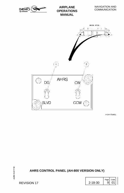
AIRPLANEOPERATIONS
MANUAL
NAVIGATION ANDCOMMUNICATION
REVISION 17 2-18-30 Page
9 Code
01
AHRS CONTROL PANEL (AH-800 VERSION ONLY)

NAVIGATION ANDCOMMUNICATION
AIRPLANEOPERATIONS
MANUAL
2-18-30 Page
10 Code
01 REVISION 25
AH-900 AHRS VERSION
The AH-900 AHRS version is basically an attitude and headingreference system that senses linear motion and angular rates throughinertial sensors. Heading orientation is also obtained through theinertial sensors, dispensing the magnetic flux detectors.
Each AHRS consists of one Attitude and Heading Reference Unit, theAHRU 1 and AHRU 2, located in the forward electronics compartment.
There are no cockpit control panels.
ATTITUDE AND HEADING REFERENCE UNIT (AHRU)
The Attitude and Heading Reference Unit contains three laser gyrosand three accelerometers that are mounted on each of the three axisinside of the AHRU, which it uses to measure inertial motion.
The AHRU requires initialization data from the Flight ManagementSystem (FMS) and Air Data Computer (ADC). From inertialmeasurements, initialization data, and air data inputs, the AHRUperforms the calculations necessary to provide heading and attitudedata to the airplane.
Each AHRU uses two 28 VDC power inputs, one for normal power(primary source) and the other for backup power (airplane batteries).The AHRU 1 primary power source is the Essential DC Bus 1 and itsbackup power source is the Backup Essential Bus. The AHRU 2primary power source is the DC Bus 2 and its backup power source isthe Backup Bus 2. If the AHRU loses primary power, it automaticallytransfers to backup power.
When the AHRU operates solely on backup power, it will operate for40 minutes and the AHRS 1 (2) ON BATT advisory message will bepresented on the EICAS.

AIRPLANEOPERATIONS
MANUAL
NAVIGATION ANDCOMMUNICATION
REVISION 25 2-18-30 Page
11 Code
01
AH-900 OPERATING MODES
ALIGNMENT MODE
The alignment mode initiates when the airplane is energized. TheAHRU aligns its reference axis to the local vertical and true north, andestimates the horizontal earth rate components to compute latitude.The latitude at which the AHRU is aligned affects the alignment time.The relationship between alignment time and latitude is shown in thechart below.
0
5
10
15
20
0 5 10 15 20 25 30 35 40 45 50 55 60 65 70 75 80
AL
IGN
ME
NT
TIM
E -
min
ute
s...
..
ALIGNMENT LATITUDE - degrees Northern and Southern
The airplane must remain stationary during alignment (AHRS 1 (2)ALN advisory message presented on the EICAS). If the AHRU detectsexcessive airplane motion (AHRS 1 (2) EXC MOTION advisorymessage is presented on the EICAS), it starts an automatic fullrealignment 30±1 seconds after the motion stops. Normal passenger-loading or cargo-loading activities should not cause excessive airplanemotion condition.
NOTE: To complete the alignment, the AHRU requires a valid input ofthe airplane’s present position (latitude and longitude) from theFMS or optionally through the MFD 1. The present positioninput through MFD 1 bezel is possible only in airplanesequipped with EICAS 18.5 and on.
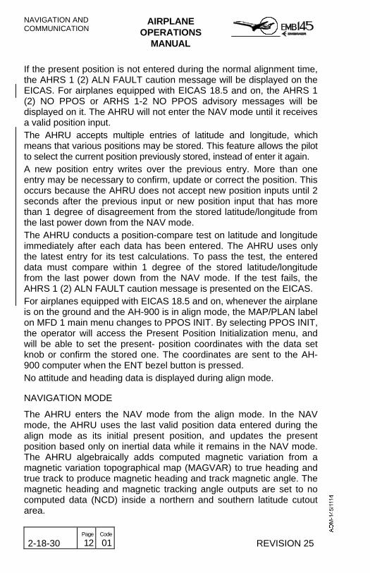
NAVIGATION ANDCOMMUNICATION
AIRPLANEOPERATIONS
MANUAL
2-18-30 Page
12 Code
01 REVISION 25
If the present position is not entered during the normal alignment time,the AHRS 1 (2) ALN FAULT caution message will be displayed on theEICAS. For airplanes equipped with EICAS 18.5 and on, the AHRS 1(2) NO PPOS or ARHS 1-2 NO PPOS advisory messages will bedisplayed on it. The AHRU will not enter the NAV mode until it receivesa valid position input.The AHRU accepts multiple entries of latitude and longitude, whichmeans that various positions may be stored. This feature allows the pilotto select the current position previously stored, instead of enter it again.A new position entry writes over the previous entry. More than oneentry may be necessary to confirm, update or correct the position. Thisoccurs because the AHRU does not accept new position inputs until 2seconds after the previous input or new position input that has morethan 1 degree of disagreement from the stored latitude/longitude fromthe last power down from the NAV mode.The AHRU conducts a position-compare test on latitude and longitudeimmediately after each data has been entered. The AHRU uses onlythe latest entry for its test calculations. To pass the test, the entereddata must compare within 1 degree of the stored latitude/longitudefrom the last power down from the NAV mode. If the test fails, theAHRS 1 (2) ALN FAULT caution message is presented on the EICAS.For airplanes equipped with EICAS 18.5 and on, whenever the airplaneis on the ground and the AH-900 is in align mode, the MAP/PLAN labelon MFD 1 main menu changes to PPOS INIT. By selecting PPOS INIT,the operator will access the Present Position Initialization menu, andwill be able to set the present- position coordinates with the data setknob or confirm the stored one. The coordinates are sent to the AH-900 computer when the ENT bezel button is pressed.No attitude and heading data is displayed during align mode.
NAVIGATION MODE
The AHRU enters the NAV mode from the align mode. In the NAVmode, the AHRU uses the last valid position data entered during thealign mode as its initial present position, and updates the presentposition based only on inertial data while it remains in the NAV mode.The AHRU algebraically adds computed magnetic variation from amagnetic variation topographical map (MAGVAR) to true heading andtrue track to produce magnetic heading and track magnetic angle. Themagnetic heading and magnetic tracking angle outputs are set to nocomputed data (NCD) inside a northern and southern latitude cutoutarea.

AIRPLANEOPERATIONS
MANUAL
NAVIGATION ANDCOMMUNICATION
MARCH 28, 2002 2-18-30 Page
13 Code
01
ATTITUDE MODE
The attitude mode is the AHRU’s reversionary mode. It is automaticallyentered by the AHRU if power is lost in flight, and it provides a quickattitude restart: during the first 20 seconds in the attitude transitionalmode, the AHRU enters the erect attitude transitional mode. In thistransitional mode the AHRS 1 (2) ALN advisory message is displayedon the EICAS and the AHRU computes a new level axis set. Theaircraft must be held steady, straight and level until the AHRS 1 (2)ALN message extinguishes.
When operating in the attitude mode the AHRS 1 (2) ATT MODEadvisory message is presented on the EICAS. In this mode, attitudeoutputs are not as accurate as when operating in the NAV mode, andmagnetic heading is not available.
For airplanes equipped with EICAS 18 and on, the AH-900 must beinitialized with magnetic heading. In this case the operator needs toknow the airplane’s magnetic heading. Whenever the airplane is in theair and the AH-900 is in attitude mode, a menu bezel buttonannunciates MHDG INIT on the pilot’s MFD. The AHRS 1 (2) NO MAGHDG or AHRS 1-2 NO MAG HDG advisory messages will be displayedon the EICAS. By selecting MHDG INIT, the operator will access theMagnetic Heading Initialization menu, and will be able to set themagnetic heading with the data set knob. The magnetic heading datais sent to the AH-900 computer when the ENT bezel button is pressed.The associated EICAS messages are cleared.
POWER-DOWN MODE
The AHRU enters the power-down mode automatically when thesystem detects an “end-of-flight” event. In this mode, the AHRU willtransfer the last calculated position and other AHRS parameters to itsnon-volatile memory.
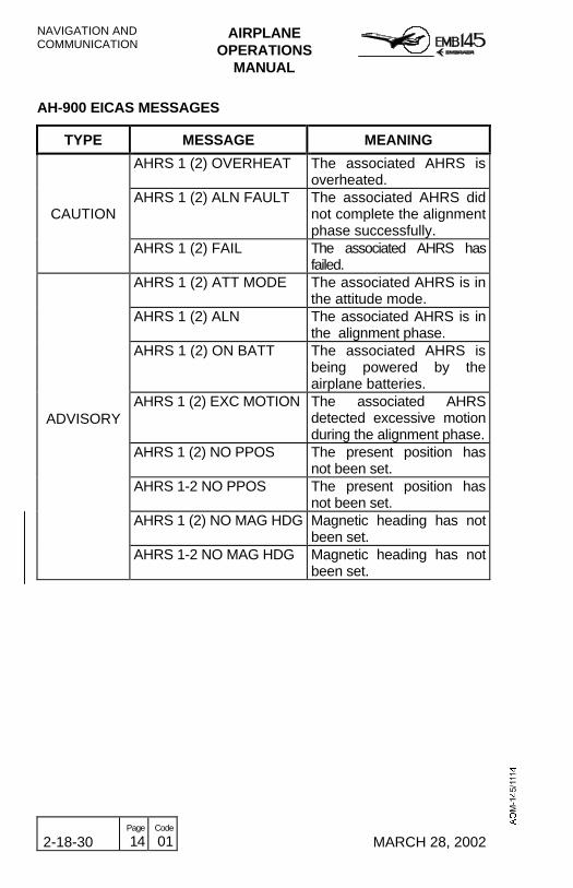
NAVIGATION ANDCOMMUNICATION
AIRPLANEOPERATIONS
MANUAL
2-18-30 Page
14 Code
01 MARCH 28, 2002
AH-900 EICAS MESSAGES
TYPE MESSAGE MEANING
AHRS 1 (2) OVERHEAT The associated AHRS isoverheated.
CAUTIONAHRS 1 (2) ALN FAULT The associated AHRS did
not complete the alignmentphase successfully.
AHRS 1 (2) FAIL The associated AHRS hasfailed.
AHRS 1 (2) ATT MODE The associated AHRS is inthe attitude mode.
AHRS 1 (2) ALN The associated AHRS is inthe alignment phase.
AHRS 1 (2) ON BATT The associated AHRS isbeing powered by theairplane batteries.
ADVISORYAHRS 1 (2) EXC MOTION The associated AHRS
detected excessive motionduring the alignment phase.
AHRS 1 (2) NO PPOS The present position hasnot been set.
AHRS 1-2 NO PPOS The present position hasnot been set.
AHRS 1 (2) NO MAG HDG Magnetic heading has notbeen set.
AHRS 1-2 NO MAG HDG Magnetic heading has notbeen set.

AIRPLANEOPERATIONS
MANUAL
NAVIGATION ANDCOMMUNICATION
MARCH 30, 2001 2-18-30 Page
15 Code
01
MAGNETIC VARIATION LATITUDE CUTOUTS (AH-900 ONLY)

NAVIGATION ANDCOMMUNICATION
AIRPLANEOPERATIONS
MANUAL
2-18-30 Page
16 Code
01 MARCH 30, 2001
AHRS INDICATIONS ON THE PFD
ELECTRONIC ATTITUDE DIRECTOR INDICATOR (EADI)
1 - ATTITUDE SPHERE− Color:
− Sky: blue.− Ground: brown.
2 - ROLL SCALE− Color: White− Range: 360 degrees.− Resolution: 10, 20, 30 and 60 degrees for left and right roll
attitudes.− Fixed pointers (unfilled triangles) are located at zero degrees
and 45 degrees (LH and RH).
3 - ROLL POINTER− Color: White.− Provides the roll angular indication against the roll scale.
4 - EXCESSIVE PITCH CHEVRONS− Color: Red− Marks –45 and 65 degrees pitch up, and 35, 50 and 65 degrees
pitch down.
5 - PITCH SCALE− Color: White.− Range: 0 to 90 degrees (pitch up and pitch down).− Marks:
− Pitch up: 0, 5, 10, 15, 20, 25, 30, 40, 60 and 90 degrees.− Pitch down: 5, 10, 15, 20, 25, 30, 45, 60 and 90 degrees.
6 - GROUND/SKY REFERENCE EYEBROW− Color: Blue or brown.− The eyebrow provides a quick ground/sky reference for attitudes
where the horizon line is out of the display.

AIRPLANEOPERATIONS
MANUAL
NAVIGATION ANDCOMMUNICATION
AUGUST 24, 2001 2-18-30 Page
17 Code
01
ELECTRONIC ATTITUDE DIRECTOR INDICATOR

NAVIGATION ANDCOMMUNICATION
AIRPLANEOPERATIONS
MANUAL
2-18-30 Page
18 Code
01 MARCH 30, 2001
ATTITUDE DECLUTTER
When there is an excessive attitude situation, certain indicators areremoved in order to declutter the PFD.
Excessive attitude situation occurs when roll attitude is greater than 65degrees, or pitch attitude greater than 30 degrees nose up or20 degrees nose down.
In this case, the following symbology shall be removed from thedisplay:
− Flight Director couple arrow,− Low Bank limit arc,− Flight Director command bars,− Vertical Deviation scale, pointer and label,− Radio Altitude digits, label and box,− Marker beacons indicators,− Decision Height digits and labels,− Selected Airspeed bug and indicators,− Vertical Speed bug and indicators,− Selected Altitude bug, indicators and box,− All failure flags associated with the items listed above,− The Heading, Radio Altitude, LOC, GS, and ILS comparison monitor
displays
The PFD indicators will be restored when both conditions below aremet:
− Roll attitude less than 63 degrees left and right.− Pitch less than 28 degrees nose up and greater than 18 degrees
nose down.

AIRPLANEOPERATIONS
MANUAL
NAVIGATION ANDCOMMUNICATION
MARCH 30, 2001 2-18-30 Page
19 Code
01
ELECTRONIC HORIZONTAL SITUATION INDICATOR (EHSI)
1 - COMPASS CARD DISPLAYMay be displayed in the Full Compass or Arc formats, selected viathe Display Control Panel (see section 2-18-40).− Color: white.− Range: 360 degrees.− Resolution: 5 degrees.
2 - HEADING LUBBER LINE (FULL COMPASS FORMAT)− Color: White.− Provides the current heading reading against the heading scale.
3 - CURRENT HEADING DIGITAL DISPLAY (ARC FORMAT)− Color:
− Open box: white− Digits: white
− Range: 0 to 360 degrees.− Resolution: 1 degree.

NAVIGATION ANDCOMMUNICATION
AIRPLANEOPERATIONS
MANUAL
2-18-30 Page
20 Code
01 MARCH 30, 2001
THIS PAGE IS LEFT BLANK INTENTIONALLY
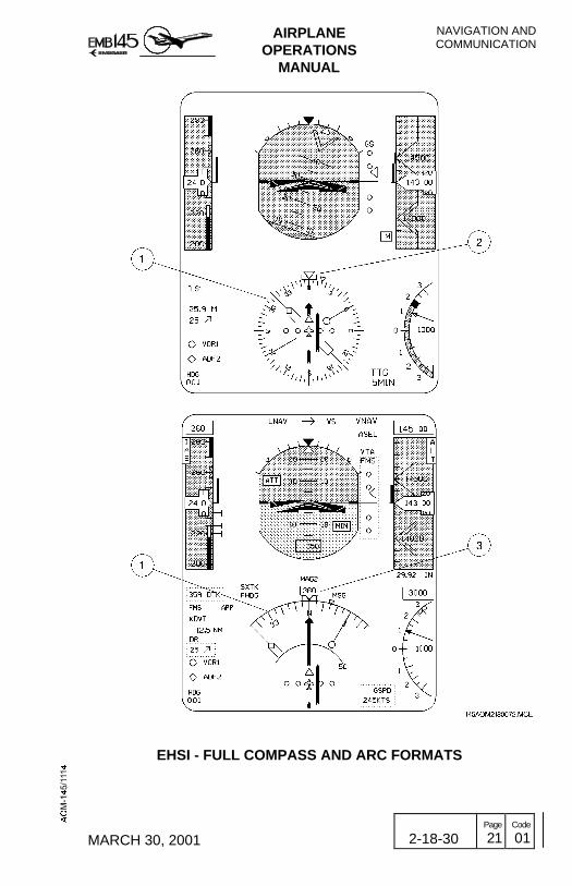
AIRPLANEOPERATIONS
MANUAL
NAVIGATION ANDCOMMUNICATION
MARCH 30, 2001 2-18-30 Page
21 Code
01
EHSI - FULL COMPASS AND ARC FORMATS

NAVIGATION ANDCOMMUNICATION
AIRPLANEOPERATIONS
MANUAL
2-18-30 Page
22 Code
01 MARCH 30, 2001
COMPARISON MONITORS
1 - ATTITUDE COMPARISON MONITOR DISPLAY− Label: ROL, PIT or ATT.− Color: Amber.− If roll information deviates by more than 6 degrees between
PFD 1 and PFD 2, a ROL comparison monitor will be displayedinside the attitude sphere.
− If pitch information deviates by more than 5 degrees betweenPFD 1 and PFD 2, a PIT comparison monitor will be displayed inthe upper-left portion of the attitude sphere.Simultaneous activation of the both pitch and roll comparisonmonitors will be announced by an ATT label displayed in theupper-left portion of the attitude sphere, in the same field of theROL and PIT comparison monitors.
2 - ATTITUDE FAILURE DISPLAY− Removal of the pitch scale and roll pointer.− Coloring the attitude sphere all blue.− A red ATT FAIL label is displayed on the top center of the
attitude sphere.
3 - ATTITUDE SOURCE ANNUNCIATION− Label: ATT1 for AHRS 1 and ATT2 for AHRS 2.− Color: Amber when one AHRS supplies both sides or both
AHRS are supplying cross-side.− Annunciations are removed when both AHRS are supplying on-
side PFDs.
4 - HEADING SOURCE ANNUNCIATION
− Label:− MAG1 or MAG2 when AHRS heading source is magnetic.− DG1 or DG2 when AHRS heading source is the directional
gyro.− Color:
– For MAG: amber when the same AHRS is supplying bothsides or both AHRS are supplying cross-side.

AIRPLANEOPERATIONS
MANUAL
NAVIGATION ANDCOMMUNICATION
MARCH 30, 2001 2-18-30 Page
23 Code
01
– For DG: - amber when the same AHRS is supplying bothsides.
- white when both AHRS are supplying on-side.− When both AHRS are supplying on-side, annunciation is
removed.− If a heading source becomes invalid the heading source
annunciation will refer to the invalid heading source, HDG1 orHDG2, as applicable.
5 - HEADING COMPARISON MONITOR DISPLAY− Color: Amber.− Label: HDG− Activated when a difference of 6 degrees between both PFDs is
detected and airplane roll is less than 6 degrees.− For airplane rolls greater than 6 degrees, annunciation will be
displayed if the difference between both PFDs is greater than12 degrees.
− The HDG threshold will be restored to 6 degrees if airplane rollis less than 5 degrees for 90 seconds. Otherwise, a 12 degreesHDG threshold will be maintained.
6 - HEADING FAILURE DISPLAY− Digital heading bug symbol is removed and a red HDG FAIL
annunciation is displayed on the PFD and MFD compass cards.− The bearing pointers, map display, To/From, selected heading
bug, drift angle, selected course/track and course deviationdisplays will be removed.
− Heading source annunciation will be HDG 1 or HDG 2.− Heading select and course select/desired track digital display
will be replaced by amber dashes.
NOTE: In case of heading splits, check if there sources for magneticinterference near the airplane. If this is cause for the problem,the heading split should disappear during the taxi.
7 - COURSE DEVIATION FAILURE− Pointer is removed.− Red X displayed over the scale.

NAVIGATION ANDCOMMUNICATION
AIRPLANEOPERATIONS
MANUAL
2-18-30 Page
24 Code
01 MARCH 30, 2001
THIS PAGE IS LEFT BLANK INTENTIONALLY
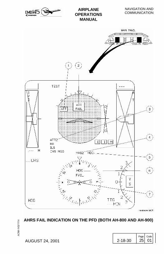
AIRPLANEOPERATIONS
MANUAL
NAVIGATION ANDCOMMUNICATION
AUGUST 24, 2001 2-18-30 Page
25 Code
01
AHRS FAIL INDICATION ON THE PFD (BOTH AH-800 AND AH-900)

NAVIGATION ANDCOMMUNICATION
AIRPLANEOPERATIONS
MANUAL
2-18-30 Page
26 Code
01 MARCH 30, 2001
THIS PAGE IS LEFT BLANK INTENTIOANALLY

AIRPLANEOPERATIONS
MANUAL
NAVIGATION ANDCOMMUNICATION
REVISION 26 2-18-35 Page
1 Code
01
FLIGHT MANAGEMENT SYSTEMThe FMZ 2000 Flight Management System (FMS) controls a completerange of navigation functions. Its primary purpose is to provide highaccuracy in long range lateral and vertical navigation. The system maybe installed with a single or dual configuration. Should the airplanehave a dual configuration, each unit can provide navigation data to theother unit. For additional information on functions and operation, referto the manufacturer’s manual.
The FMS is mainly composed of the following components:
− Control Display Unit (CDU).− Navigation Computer (NZ).− Data Loader (DL) or Portable Data Transfer Unit (PDTU).
The FMS operates in the following situations: Oceanic, Remote, NorthAtlantic Minimum Navigation Performance Specification Airspace,Enroute, Terminal, Non-Precision Approach and Required NavigationPerformance 10.
The FMS interfaces with the followings systems and equipment:
− GPS sensor(s), ADC 1 and 2 - The GPS receives satellite datathrough the passive GPS antenna, processing and blending collecteddata with ADC data and sends the resulting information to the FMScomputer.
− AHRS/IRS 1 and 2 - Provides the necessary data to compute windand for Dead Reckoning Mode, when the subsystem is not capableof navigating by itself.
− MFD and PFD - The FMS provides data for display navigationguidance on the PFD and navigation map data on the MFD.
− RMU 1 and 2 - The RMU interfaces with the FMS computer tocontrol the operating frequencies, modes and channels of thevarious radios. For the dual configuration, each RMU supplies eachrespective on-side NZ.
− COM 1 and 2, NAV 1 and 2 - The FMS includes a radio-tuning pageon which the pilot can manually select the VHF NAV and COMfrequencies. Only the NAV frequency is fed back to the FMScomputer for verification of the tuning action. COM 1 and 2 interfacewith FMS through the RMUs. The FMS can also automatically selectthe NAV radio frequencies. The FMS tune function for tuningcommunication frequencies with 8.33 kHz frequency spacing isavailable only for the Honeywell NZ5.2 FMS software version.
− The FMS also provides latitude and longitude to TCAS.

NAVIGATION ANDCOMMUNICATION
AIRPLANEOPERATIONS
MANUAL
2-18-35 Page
2 Code
01 REVISION 23
The Control Display Unit (CDU), located on the control pedestal,provides control functions management and operating modes forproper FMS operation. The EMB-145 should have two types of FMZ2000 CDU installed, CD-810 or CD-820. In dual FMS configuration, theintermix operation is not recommended.
The CD-810 CDU is equipped with a Cathodic Ray Tube (CRT). TheCD-820 CDU is equipped with a full-color Liquid Crystal Display (LCD)and contains nine lines, being the first a title line and the ninth thescratchpad.

AIRPLANEOPERATIONS
MANUAL
NAVIGATION ANDCOMMUNICATION
REVISION 18 2-18-35 Page
3 Code
01
FMS SCHEMATIC

NAVIGATION ANDCOMMUNICATION
AIRPLANEOPERATIONS
MANUAL
2-18-35 Page
4 Code
01 REVISION 28
FMS OPERATING MODES
FMS FUNCTIONS
NAVIGATION
The navigation function computes the airplane position and velocity forall phases of flight. The navigation priority modes, based on sensoraccuracy, are as follows:
− GPS− DME/DME− VOR/DME− IRS (if installed)
The GPS is the most accurate sensor. When the GPS is in use, theother sensors are still monitored for position differences, but they donot contribute to FMS position, unless the GPS becomes inaccurate,unavailable or is manually deselected. In this case, the FMSautomatically tunes the DME/DME in order to provide position. WhenDME/DME is not accurate, the VOR/DME is selected.
On airplanes equipped with dual Inertial Reference System (IRS),replacing the AHRS, the IRS is used as a primary navigation sensorwhen other navaid are not available.
If all position sensors and radios are lost, the FMS shifts to DegradeMode (DGRAD) and in approximately 2 minutes it enters the DeadReckoning Mode (DR). In this mode, the position is calculated usingthe last known airplane position. The ground speed and track areestimated with AHRS/IRS heading, ADC TAS and the last known winddata.
The dual FMS configuration (NZ5.2 software version and on) mayoperate with dual IRS and dual GPS providing four long-rangenavigation sensors. The sensors status may be accessed in the NAVINDEX 1/2 page.
In this configuration, on-side FMS outputs and flight plan informationare available to the opposite-side FMS through an interconnecting bus.
The automatic tuning is made through the RMU for computing anoptimum position. The FMS also includes a radio-tuning page on whichthe pilot can manually select VHF NAV, COM, ADF and transponderfrequencies. The NZ5.2 software version and on has the capability oftuning communication frequencies in the 8.33 kHz channel spacing.
AIRPLANEOPERATIONS
MANUAL
NAVIGATION ANDCOMMUNICATION
MARCH 30, 2001 2-18-35 Page
5 Code
01
FLIGHT PLANNING
The flight planning function computes the active flight plan with bothlateral and vertical definition.
When the FMS long-range navigation is selected, the flight directorcommand bars will provide the visual command to bank the airplane tothe desired track.
The VNAV is applicable only for the descent path and it is not coupledto the flight director, being only a reference information displayed onthe PFD glide slope scale.
Additionally the navigation computer can be programmed by theoperator to automatically fly different types of holding patterns.
DATA BASE
The database contains worldwide coverage of navaids, airways,departure procedures, approach procedures, Standard TerminalArrival Routes (STARs), airports and runways. This information isupdated every 28 days. The database can also store up to 200 pilot-defined flight plans and waypoints, which are only updated whenchanged by the pilot.
In single configuration, the Data Loader (DL) is used to update theDatabase, transferring data to and from the Navigation Computer. Inthis configuration, this unit can be installed on the left lateral console,close to the pilot’s mask stowage box.
In dual configuration, the Portable Data Transfer Unit (PDTU) is usedto reload entire information package at each update by using a 3 1/2"floppy disk.
NAVIGATION DISPLAY
A multiple waypoints map, based on the airplane’s present position,can be displayed on the MFD. It comprises the Waypoints connectedby white lines defining a pre-planned route, and also navaids andairports.

NAVIGATION ANDCOMMUNICATION
AIRPLANEOPERATIONS
MANUAL
2-18-35 Page
6 Code
01 MARCH 30, 2001
FMS MODES
The dual FMS configuration provides four operating modes that maybe accessed through the FMS MAINTENANCE 1/3 page:
DUAL MODE
In this mode, the following information is automatically transferred tothe cross-side FMS: flight plan, performance data, waypoints definedby the pilot, flight plans created in one system and radio tuning.
NOTE: For the proper operation in DUAL mode it is necessary to usethe same software version, same NAV and CUSTOM databases and same settings for both systems in the ConfigurationModules. The initial position difference between both systemsshall not be more than 10 NM.
INITIATED TRANSFER MODE
In this mode the flight plan and performance data entry will only betransferred to the cross-side FMS through the prompt commandavailable in the last page of the ACTIVE FLT PLAN pages. Waypointsdefined by the pilot, created flight plans and radio tuning areautomatically transferred to the cross-side FMS.
NOTE: For the proper operation in INITIATED TRANSFER mode it isnecessary to use the same software version, same NAV andCUSTOM data bases and same settings for both systems inthe Configuration Modules. The initial position differencebetween both systems shall not be more than 10 NM.
INDEPENDENT MODE
In this mode, only the radio tuning is automatically transferred to thecross-side FMS.
NOTE: To operate in the INDEPENDENT mode, it is necessary to usethe same software version and same settings in theConfiguration Modules. If any of these requirements is notaccomplished, the system automatically passes for thepossible operating mode. For instance, if only the CUSTOMdatabase differs in both systems, the operating modeautomatically switches from DUAL to INDEPENDENT.
SINGLE MODE
No information is exchanged between both systems.

AIRPLANEOPERATIONS
MANUAL
NAVIGATION ANDCOMMUNICATION
JUNE 28, 2002 2-18-35 Page
7 Code
01
FMS CONTROLS AND INDICATORS
CONTROL DISPLAY UNIT (CDU)
1 - ANNUNCIATORS
The CD-810 CDU has the annunciator lights directly above the displayand the CD-820 CDU has the annunciators on the top of LCD display.
− Colors:− White: indicating advisory annunciation.− Amber: indicating alerting annunciation.
DSPLY (White) Illuminates when the CDU displays a page thatis not relative to the current airplane lateral orvertical flight path. This annunciator is notshown on the PFD.
DR (Amber) Illuminates when a radio updating loss occurs,as well as all other position sensors, for a periodlonger than 2 minutes.
DGRAD (Amber) Illuminates when the FMS cannot guarantee theposition accuracy for the present phase of theflight.
MSG (White) Illuminates when there is a message (advisoryor alert) on the scratchpad. The annunciatorturns off when the message is cleared from thescratchpad.
OFFSET (White) Illuminates when a lateral offset path has beenentered in the FMS. The annunciator turns offwhen the offset is removed.
APRCH (White) Illuminates when the FMS is selected asnavigation source and the following conditionsare valid: a non-precision instrument approachhas been activated from the navigationdatabase, the airplane position is between 2 NMoutside the final approach fix and the missedapproach point, the DGRAD must be off andFMS using approved sensors for non-precisionapproach.
NOTE: The FMS transmits all the annunciators to the PFD, except theDSPLY annunciator, so the pilot must not trust only on the FMSCDU for checking the FMS system status.

NAVIGATION ANDCOMMUNICATION
AIRPLANEOPERATIONS
MANUAL
2-18-35 Page
8 Code
01 JUNE 28, 2002
2 - LINE SELECT BUTTONS− There are four line select buttons on each side of the CDU that
provide the following functions:− Select submodes within major modes when in an indexed
display.− Used as direct access to the other FMS modes when in a
non-indexed display.− Enter data to the scratchpad.
3 - BRIGHTNESS CONTROL KNOB/BUTTON− Used to manually control the brightness of the display.− After using this knob, the photo sensors are activated and
maintain the brightness level through a wide range of lightingconditions. In CD-820 CDU the brightness is adjusted pressingup or down the Bright/Dim button, so a control bar will bedisplayed in the scratchpad.
− The brightness can be adjusted so that, during daylightconditions, the display cannot be seen.
4 - MODE BUTTONSPERF Displays the performance pages.
NAV Displays the NAV index pages.
FPL It may be used to display the first page of the activeflight plan, if the flight plan was previously entered, tomanually create a flight plan, to select a stored flightplan and to create a flight plan for storage.
PROG Displays the first progress page, the current status ofthe flight.
DIR Displays the active flight plan with the DIRECT andINTERCEPT prompts.
5 - ALPHANUMERIC BUTTONS− Consist of alphabet letters, the numbers 0 through 9, a
decimal, a dash and a slash. It is used to enter inputs to theFMS. In the CD-820 a SP (Space) key is used to insert aspace following a character in the scratchpad, and a +/-(Plus/Minus) key will result in a - being entered, changing to +in a subsequent press.
− The alphanumeric keys make entries only on the scratchpad.

AIRPLANEOPERATIONS
MANUAL
NAVIGATION ANDCOMMUNICATION
JUNE 28, 2002 2-18-35 Page
9 Code
01
6 - FUNCTIONS BUTTONSPREV Changes the current page to the previous page.
NEXT Changes the current page to the next page.
CLR Clears alphanumeric entries in the scratchpad or ascratchpad message.
DEL Works together with line select buttons in order to deletewaypoints and other items displayed on the CDU. Thisbutton is inhibited when a message is displayed.
The CD-820 has five function buttons directly above the LCD displaythat will not work if pressed. The following messages will be displayedin the scratchpad:
VIDEO VIDEO NOT AVAILABLE.GRAPHIC GRAPHIC NOT AVAILABLE.ATC ATC NOT AVAILABLE.BACK BACK COMPLETE.FN FN NOT AVAILABLE.
7 - SCRATCHPAD− It is the working area, located on the bottom line of the display,
where the pilot can enter data and/or verify data before lineselecting the data into its proper position.
− Data is retained on the scratchpad throughout all mode andpage changes.
− The scratchpad also provides advisory and alerting messages tobe displayed.
The colors on the CD-820 are designed to highlight importantinformation. Color assignments are coordinated as much as possiblewith other displays. See below the parameters associated to eachcolor:
Vertical Cyan (Blue)Atmospheric Data Cyan (Blue)Lateral GreenFROM Waypoint YellowTO Waypoint MagentaPrompts and Titles WhiteFlight Plan Names OrangeIndex Selections Green

NAVIGATION ANDCOMMUNICATION
AIRPLANEOPERATIONS
MANUAL
2-18-35 Page
10 Code
01 JUNE 28, 2002
FMZ 2000 FMS CD-810 CONTROL PANEL

AIRPLANEOPERATIONS
MANUAL
NAVIGATION ANDCOMMUNICATION
JUNE 28, 2002 2-18-35 Page
11 Code
01
FMZ 2000 FMS CD-820 CONTROL PANEL

NAVIGATION ANDCOMMUNICATION
AIRPLANEOPERATIONS
MANUAL
2-18-35 Page
12 Code
01 JUNE 28, 2002
JOYSTICK (OPTIONAL)
The joystick functions are available through the joystick controller thatis located on the control pedestal and through the selection of the MFDJSTK menu.
When the MFD joystick menu is selected, the joystick controller isavailable to control the Designator Symbol movement on the MFDFMS flight plan.
JOYSTICK OPERATION
On power-up, the designator is co-located with the present flight planwaypoint position.
If MAP mode is selected, moving the joystick controller, will cause theDesignator Symbol to be displayed in blue color with a broken linewhich moves in the same direction from its last waypoint position.
If PLAN mode is selected, moving the joystick controller, the flight planmoves to the opposite direction from its last position, while theDesignator Symbol remains fixed at the center of the plan format.

AIRPLANEOPERATIONS
MANUAL
NAVIGATION ANDCOMMUNICATION
AUGUST 24, 2001 2-18-35 Page
13 Code
01
JOYSTICK CONTROLLER
NAVIGATION ANDCOMMUNICATION
AIRPLANEOPERATIONS
MANUAL
2-18-35 Page
14 Code
01 JUNE 28, 2002
JOYSTICK MENU BUTTONS FUNCTION AT MAP MODE
− SKIP ("SKP") button: Skips the designator to the position of the nextwaypoint in the flight plan in case of the designator is co-locatedwith a plan waypoint. Otherwise, the designator broken line tailskips to the next waypoint in the flight plan.
− RECALL ("RCL") button: Positions the designator at the presentposition of the airplane and removes the designator box from thedisplay in case of the designator is co-located with the flight planwaypoint. Otherwise, the designator is positioned over the waypointfrom which the designator line is extended and the designator line isremoved from the display.
− ENTER ("ENT") button: The latitude and longitude coordinates ofthe designator are transmitted to the selected FMS scratchpad as arequested waypoint.
JOYSTICK MENU BUTTONS FUNCTION AT PLAN MODE
− SKIP ("SKP") button: Positions the flight plan so the next waypointis displayed over the designator in case of the designator is co-located with a flight plan waypoint. Otherwise, skips the tail of thedesignator line to the next waypoint in the flight plan.
− RECALL ("RCL") button: Positions the designator at the presentposition of the airplane and removes the designator box from thedisplay in case of the designator is co-located with a flight planwaypoint. Otherwise, it positions the designator over the waypointfrom which the designator line is extended and removes thedesignator line from the display.
− ENTER ("ENT") button: The latitude and longitude coordinates ofthe designator are transmitted to the selected FMS scratchpad as arequested waypoint.

AIRPLANEOPERATIONS
MANUAL
NAVIGATION ANDCOMMUNICATION
REVISION 29 2-18-35 Page
15 Code
01
MFD JOYSTICK MENU

NAVIGATION ANDCOMMUNICATION
AIRPLANEOPERATIONS
MANUAL
2-18-35 Page
16 Code
01 REVISION 23
THIS PAGE IS LEFT BLANK INTENTIONALLY

AIRPLANEOPERATIONS
MANUAL
NAVIGATION ANDCOMMUNICATION
MARCH 30, 2001 2-18-40 Page
1 Code
01
NAVIGATION DISPLAYSThe navigation data provided by the Radio Management System andFlight Management System are displayed to the crew through thePFDs, MFDs and RMUs.
ADF and/or VHF NAV bearings and VHF NAV or FMS CDI (CourseDeviation Indicator) are displayed on the PFD in an ElectronicHorizontal Situation Indicator (EHSI). The EHSI navigation sources aswell as the display format (Full Compass or Arc) may be selected bythe crew via the Display Control Panel (DCP).
Several other navigation data are also presented on the PFDs: GS(Glide Slope) pointer, DME distance, Ground Speed/Time-to-go,marker beacon indicators, wind intensity and direction vector, etc.
The MFDs present Weather Radar, TCAS and the route selected onthe FMS. Additional information is also presented on the MFD: windintensity and direction vector, TAS, Time-to-go, etc.
The RMUs NAV Backup Page also present the EHSI, in the Arc formatonly (see section 2-18-11).

NAVIGATION ANDCOMMUNICATION
AIRPLANEOPERATIONS
MANUAL
2-18-40 Page
2 Code
01 MARCH 30, 2001
DISPLAYS CONTROLS AND INDICATORS
DISPLAY CONTROL PANEL (DCP)
1 - DISPLAY FORMATS SELECTOR BUTTON− Pressing the FULL/WX Button alternates the EHSI presentation
on the PFD between Full Compass format and Arc format.− In Arc format the Weather Radar Display is also presented
whenever the Weather Radar is operating.
2 - GROUND SPEED AND TIME-TO-GO SELECTOR BUTTON− Pressing the GSPD/TTG Button alternates the respective
information on the PFD between ground speed and time-to-go.
3 - ELAPSED TIME SELECTOR BUTTON − The first actuation enters the Elapsed Time Mode on the PFD
respective field. The subsequent actuation provides thefollowing sequence of control: RESET - ELAPSED TIME -STOP - REPEAT.
4 - NAVIGATION SOURCES SELECTOR BUTTON − Provides the selection of the VHF NAV (VOR, ILS and MLS) as
navigation source for the EHSI. If the VHF NAV is alreadyselected, pressing the NAV Button selects the opposite VHFNAV as navigation source for the on-side EHSI. Pressing theNAV Button once again will restore the normal operation: VHFNAV 1 information presented on the PFD 1 and VHF NAV 2information presented on the PFD 2.
5 - FMS SOURCE SELECTOR BUTTON (OPTIONAL) − Provides the selection of the FMS as navigation source for the
EHSI.− On airplanes equipped with dual FMS, pressing the FMS Button
for the second time selects the opposite FMS as navigationsource for the on-side EHSI (and for the on-side MFD MAP).Pressing the FMS Button once again will restore the normaloperation: FMS 1 information presented on the PFD 1 (and MFD1) and FMS 2 information presented on the PFD 2 (and MFD 2).

AIRPLANEOPERATIONS
MANUAL
NAVIGATION ANDCOMMUNICATION
MARCH 30, 2001 2-18-40 Page
3 Code
01
6 - BEARING SELECTOR KNOBOFF: The associated PFD bearing pointers are disabled.NAV 1 (2): Selects the respective VHF NAV as source for the
associated bearing pointer.ADF: Selects the respective ADF as source for the
associated bearing pointer.FMS: Selects the FMS as source for the associated bearing
pointer.
7- DECISION HEIGHT SETTING AND IC-600 TEST KNOB − Provides the Radio Altimeter (RA) decision height setting.− When pressed on ground provides the IC-600 and RA test
activation. Refer to Section 2-4 – Crew Awareness for furtherinformation on test function and Section 2-17 – FlightInstruments for further information on decision height settingand RA test in flight.

NAVIGATION ANDCOMMUNICATION
AIRPLANEOPERATIONS
MANUAL
2-18-40 Page
4 Code
01 MARCH 30, 2001
THIS PAGE IS LEFT BLANK INTENTIONALLY

AIRPLANEOPERATIONS
MANUAL
NAVIGATION ANDCOMMUNICATION
AUGUST 24, 2001 2-18-40 Page
5 Code
01
DISPLAYS CONTROL PANEL

NAVIGATION ANDCOMMUNICATION
AIRPLANEOPERATIONS
MANUAL
2-18-40 Page
6 Code
01 MARCH 30, 2001
FMS SOURCE SELECTION ON THE MFD
As explained on the Display Control Panel (DCP) description (seesection 2-18-40), pressing the FMS Button on that panel selects theFMS as navigation source for the PFD and MFD.
On airplanes equipped with dual FMS, pressing the FMS Button (onthe Display Control Panel) for the second time selects the oppositeside FMS as navigation source for the on-side EHSI (and for the on-side MFD MAP). Pressing the FMS Button once again will restore thenormal operation: FMS 1 information presented on the PFD 1 (andMFD 1) and FMS 2 information presented on the PFD 2 (and MFD 2).
However, on airplanes equipped with dual FMS it is possible to selectthe opposite side FMS as MFD navigation source even if the FMS isnot selected as navigation source for the PFD.
In this case, pressing the MFD Bezel Button adjacent to the MFD SRClabel (presented on the MFD submenu), the on-side MFD will displaythe opposite side FMS data. This label is not presented if the FMS isalready selected as navigation source for the PFD.
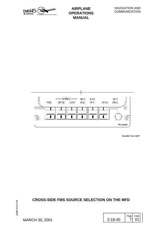
AIRPLANEOPERATIONS
MANUAL
NAVIGATION ANDCOMMUNICATION
MARCH 30, 2001 2-18-40 Page
7 Code
01
CROSS-SIDE FMS SOURCE SELECTION ON THE MFD

NAVIGATION ANDCOMMUNICATION
AIRPLANEOPERATIONS
MANUAL
2-18-40 Page
8 Code
01 MARCH 30, 2001
ADF, VHF NAV AND DME INDICATIONS ON THE PFD
1 - VERTICAL DEVIATION DISPLAY− Color:
− Scale: white− GS Pointer: - green
- yellow if the same source is supplying bothsides.
− GS label: green.− For glide slope presentation the pointer will be parked up or
down of the deviation display when the deviation exceeds theexternal dots.
− Glide slope information will be displayed when SRN NAV isselected for display and tuned to LOC is active.
2 - MARKER BEACON DISPLAY− Color:
− O label: cyan.− M label: amber.− I label: white.− Box: white.
− An O, an M or an I flashing annunciation is displayed when theouter marker, the middle marker or the inner marker is detected,respectively.
− A beacon box surrounding the MB flashing annunciations will beshown when a SRN is displayed, tuned-to-localizer is active anda marker is also active.
3 - BEARING POINTER− Color:
− Cyan for Bearing 1− White for Bearing 2
− Circle coded for #1 source {VOR 1, ADF (for single installation)or ADF 1 (for dual installation)}.
− Diamond coded for #2 source {VOR 2, ADF (for singleinstallation) or ADF 2 (for dual installation)}.
− Pointer is removed if the selected source signal is invalid.
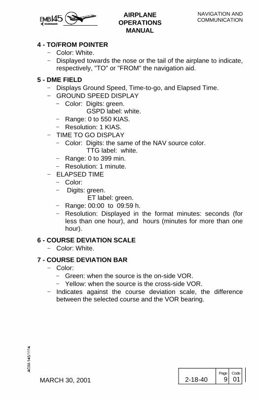
AIRPLANEOPERATIONS
MANUAL
NAVIGATION ANDCOMMUNICATION
MARCH 30, 2001 2-18-40 Page
9 Code
01
4 - TO/FROM POINTER− Color: White.− Displayed towards the nose or the tail of the airplane to indicate,
respectively, "TO" or "FROM" the navigation aid.
5 - DME FIELD− Displays Ground Speed, Time-to-go, and Elapsed Time.− GROUND SPEED DISPLAY
− Color: Digits: green.GSPD label: white.
− Range: 0 to 550 KIAS.− Resolution: 1 KIAS.
− TIME TO GO DISPLAY− Color: Digits: the same of the NAV source color.
TTG label: white.− Range: 0 to 399 min.− Resolution: 1 minute.
− ELAPSED TIME− Color:− Digits: green.
ET label: green.− Range: 00:00 to 09:59 h.− Resolution: Displayed in the format minutes: seconds (for
less than one hour), and hours (minutes for more than onehour).
6 - COURSE DEVIATION SCALE− Color: White.
7 - COURSE DEVIATION BAR− Color:
− Green: when the source is the on-side VOR.− Yellow: when the source is the cross-side VOR.
− Indicates against the course deviation scale, the differencebetween the selected course and the VOR bearing.

NAVIGATION ANDCOMMUNICATION
AIRPLANEOPERATIONS
MANUAL
2-18-40 Page
10 Code
01 MARCH 30, 2001
8 - BEARING SOURCE ANNUNCIATIONS− Label: VOR1, VOR2, ADF1 or ADF2.− Color:
− Cyan for Bearing 1− White for Bearing 2
− Circle coded for #1 source {VOR 1, ADF (for single installation)or ADF 1 (for dual installation)}.
− Diamond coded for #2 source {VOR 2, ADF (for singleinstallation) or ADF 2 (for dual installation)}.
− Indicates the current source of input to the bearing pointers.− Source annunciation will be retained on the PFD, even in case
of an invalid bearing signal.
9 - DME HOLDING AND DISTANCE ANNUNCIATION− Color:
− Digits: green.− NM label: white.− H label: amber.
− Range:− Short Range NAV: 0 to 300 NM.
− Resolution: 0.1 NM.− When the DME hold is active an H label is displayed on the RH
of the DME distance digital readout. In this condition the H labelreplaces the distance NM label.
10 - COURSE DEVIATION NAV SOURCE ANNUNCIATION− Label: VOR1, VOR2, ILS1, ILS2 or FMS (optional)– Color:
– Yellow: when the same source is selected for both sides oris supplying cross-side.
– Green: when both sides present on-side sources, even ifthey are different.

AIRPLANEOPERATIONS
MANUAL
NAVIGATION ANDCOMMUNICATION
MARCH 30, 2001 2-18-40 Page
11 Code
01
ADF, VHF NAV AND DME INDICATIONS ON THE PFD(EHSI IN FULL COMPASS FORMAT)

NAVIGATION ANDCOMMUNICATION
AIRPLANEOPERATIONS
MANUAL
2-18-40 Page
12 Code
01 MARCH 30, 2001
THIS PAGE IS LEFT BLANK INTENTIONALLY

AIRPLANEOPERATIONS
MANUAL
NAVIGATION ANDCOMMUNICATION
MARCH 30, 2001 2-18-40 Page
13 Code
01
ADF, VHF NAV AND DME INDICATIONS ON THE PFD(EHSI IN ARC FORMAT)

NAVIGATION ANDCOMMUNICATION
AIRPLANEOPERATIONS
MANUAL
2-18-40 Page
14 Code
01 MARCH 30, 2001
FMS INDICATION ON THE PFD
1 - VERTICAL ALERT ANNUNCIATION− Label: VTA− Color: Amber− The VTA is displayed when the vertical alert bit is received from
the FMS.
2 - VERTICAL DEVIATION DISPLAY− When the FMS VNAV is selected the Vertical Deviation is
activated.− The Vertical Deviation Display indicates the vertical deviation
between the airplane and the selected vertical path.− Label: FMS− Color: Amber
− The FMS label and the scale are white.− If the FMS is the navigation source for only one side, the
pointer will be magenta, otherwise it will be amber.
3 - MESSAGE ANNUNCIATION− Label: MSG− Color: Amber− The MSG is displayed when a message is available on the FMS
Panel.
4 - GROUND SPEED/TIME TO GO DATA− Label: GSPD for Ground Speed. TTG for Time To Go.− Color: Labels and units are white.
− For single configuration, if the FMS is the navigation sourcefor only one side, the GSPD and TTG readouts will bemagenta, otherwise, they will be amber.
− For dual configuration, if each FMS is the navigation sourceof the respective side, the GSPD and TTG readouts will bemagenta. Otherwise, they will be amber.
− The Ground Speed unit is knots (KTS) and the Time To Go unitis minutes (MIN).
− The resolution of the digital values is 1 unit.− For invalid values, the digits will be replaced with three amber
dashes.

AIRPLANEOPERATIONS
MANUAL
NAVIGATION ANDCOMMUNICATION
MARCH 30, 2001 2-18-40 Page
15 Code
01
5 - DRIFT ANGLE BUG− Color: Magenta.− The Drift Angle Bug rotates around the compass card, providing
the reading of the airplane tracking.
6 - COURSE DEVIATION BAR− Color: If the FMS is the navigation source for only one side, the
Course Deviation Bar will be magenta, otherwise, it will beamber.
7 - TO/FROM POINTER− Color: White.
8 - BEARING POINTER− Color: Cyan for Bearing 1 (circle shaped).
White for Bearing 2 (diamond shaped).
9 - BEARING SOURCE ANNUNCIATIONS− Color: Cyan for Bearing 1 (circle shaped).
White for Bearing 2 (diamond shaped) in single FMSconfiguration.In dual configuration there will be an indication if FMS 1or 2 is being used.
10 - WIND VECTOR DISPLAY− Color: Magenta.− A single vector shows the direction of the wind relative to the
airplane symbol. The digits indicate the wind intensity in knots.
11 - DEGRADE MODE/DEAD RECKONING MODE/WAYPOINTANNUNCIATIONS− Label: DGRAD for Degrade Mode (single FMS configuration only)
DR for Dead Reckoning mode.WPT for waypoint.
− Color: Amber− WPT is lit when the airplane is approaching the next waypoint.
12 - DISTANCE DISPLAY− Color:
− In single configuration, if the FMS is the navigation sourcefor only one side, the distance readout will be magenta.Otherwise, it will be amber.
− In dual configuration, if each FMS is the navigation sourceof the respective side, the distance readout will bemagenta, otherwise it will be amber.
− The unit is white.− The distance unit is nautical miles (NM).

NAVIGATION ANDCOMMUNICATION
AIRPLANEOPERATIONS
MANUAL
2-18-40 Page
16 Code
01 MARCH 30, 2001
13 - TO WAYPOINT SYMBOL− Label: Waypoint identifier name (Ex: KDVT).− Color: Magenta. For dual configuration, when using cross-side
information, the color is amber.− In the sequence established, the TO waypoint is the next one
from the current airplane position.
14 - APPROACH/TERMINAL AREA ANNUNCIATIONS− Label: APP for Approach.
TERM for Terminal Area.− Color: Cyan.− When APP is displayed it indicates that the FMS is in the flight
approach phase and also can indicate that the lateral deviationscaling has been set to approach scale factor.
− In the APP mode the deviation indicator sensitivity and FMStracking gains are increased.
− The TERM annunciator is displayed when the airplane entersin the terminal area or when the lateral deviation scaling hasbeen set to the enroute scale factor.
− Priority is given to the APP message.
15 - FMS SOURCE ANNUNCIATION− Label: FMS.− Color:
− For single configuration, if the FMS is the navigation sourcefor only one side, the FMS label will be magenta.Otherwise, it will be amber.
− For dual configuration, if each FMS is the navigation sourcefor the respective side, the FMS label will be magenta,otherwise it will be amber.
− FMS is displayed only when a single source is installed.
16 - HEADING ANNUNCIATION− Label: HDG SEL (For dual FMS configuration).− Color: White. For dual configuration, if each FMS is the
navigation source for the respective side the color will be white, otherwise it will be amber.

AIRPLANEOPERATIONS
MANUAL
NAVIGATION ANDCOMMUNICATION
MARCH 30, 2001 2-18-40 Page
17 Code
01
17 - SELECTED COURSE/DESIRED TRACK ANNUNCIATIONS ANDREADOUTS− Label: DTK for Desired Track.
CRS for Selected Course.− Color:
− For single configuration, if the FMS is the navigation sourcefor only one side, the CRS label will be green and DTK willbe magenta. Otherwise, both labels will be amber.
− For dual configuration, if each FMS is the navigation sourcefor the respective side, the CRS and DTK labels will bemagenta. Otherwise they will be amber.
− The readouts will have the same color as the CRS and DTKannunciations.
− DTK is displayed when the FMS is the selected navigationsource.
18 - CROSSTRACK ANNUNCIATION− Label: SXTK− Color:
− For single configuration, if the FMS is the navigation sourcefor only one side the label will be magenta, otherwise it willbe amber.
− For dual configuration: The color will be ever amber.
− SXTK is displayed to indicate that the airplane is off track.
19 - CAPTURED LATERAL MODE− Refer to Section 2-19 - Autopilot.

NAVIGATION ANDCOMMUNICATION
AIRPLANEOPERATIONS
MANUAL
2-18-40 Page
18 Code
01 MARCH 30, 2001
THIS PAGE IS LEFT BLANK INTENTIONALLY
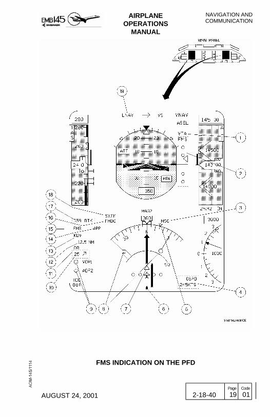
AIRPLANEOPERATIONS
MANUAL
NAVIGATION ANDCOMMUNICATION
AUGUST 24, 2001 2-18-40 Page
19 Code
01
FMS INDICATION ON THE PFD
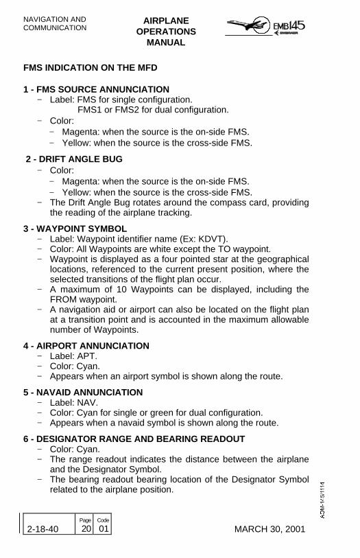
NAVIGATION ANDCOMMUNICATION
AIRPLANEOPERATIONS
MANUAL
2-18-40 Page
20 Code
01 MARCH 30, 2001
FMS INDICATION ON THE MFD
1 - FMS SOURCE ANNUNCIATION− Label: FMS for single configuration.
FMS1 or FMS2 for dual configuration.− Color:
− Magenta: when the source is the on-side FMS.− Yellow: when the source is the cross-side FMS.
2 - DRIFT ANGLE BUG− Color:
− Magenta: when the source is the on-side FMS.− Yellow: when the source is the cross-side FMS.
− The Drift Angle Bug rotates around the compass card, providingthe reading of the airplane tracking.
3 - WAYPOINT SYMBOL− Label: Waypoint identifier name (Ex: KDVT).− Color: All Waypoints are white except the TO waypoint.− Waypoint is displayed as a four pointed star at the geographical
locations, referenced to the current present position, where theselected transitions of the flight plan occur.
− A maximum of 10 Waypoints can be displayed, including theFROM waypoint.
− A navigation aid or airport can also be located on the flight planat a transition point and is accounted in the maximum allowablenumber of Waypoints.
4 - AIRPORT ANNUNCIATION− Label: APT.− Color: Cyan.− Appears when an airport symbol is shown along the route.
5 - NAVAID ANNUNCIATION− Label: NAV.− Color: Cyan for single or green for dual configuration.− Appears when a navaid symbol is shown along the route.
6 - DESIGNATOR RANGE AND BEARING READOUT− Color: Cyan.− The range readout indicates the distance between the airplane
and the Designator Symbol.− The bearing readout bearing location of the Designator Symbol
related to the airplane position.

AIRPLANEOPERATIONS
MANUAL
NAVIGATION ANDCOMMUNICATION
MARCH 30, 2001 2-18-40 Page
21 Code
01
7 - TO WAYPOINT SYMBOL− Color:
− Magenta: when the source is the on-side FMS.− Yellow: when the source is the cross-side FMS.
− In the sequence established, the TO Waypoint is the next onefrom the current airplane position.
8 - LATERAL DEVIATION DISPLAY− Color: White.− Right after the values there is a letter which may be L or R
standing for Left and Right respectively.
9 - WIND VECTOR DISPLAY− Color:
− Magenta: when the source is the on-side FMS.− Yellow: when the source is the cross-side FMS.
− A single vector shows the direction of the wind relative to theairplane symbol. The digits indicate the wind intensity in knots.
10 - DESIGNATOR SYMBOL− Color:
− Same color of the Waypoint: If the Designator is co-locatedwith a connected Waypoint.
− Cyan: If it is not connected.− The Designator symbol is displayed as an unfilled rectangle
applied in two distinct methods: co-located with a Waypoint orpositioned with the joystick.
− Designator will not be displayed if it represents the currentposition.
11 - TO WAYPOINT DATA ANNUNCIATIONS− It is composed of the annunciators and presented as follows:
− Identification.− Distance in nautical miles (NM).− Time to the TO Waypoint in minutes (MIN).voyeur
− Color:− For single FMS configuration the identification is magenta.
The distance and the time are white.− For dual FMS configuration the identification, distance and
time are magenta, when the source is the on-side FMS, oryellow, when the source is the cross-side FMS

NAVIGATION ANDCOMMUNICATION
AIRPLANEOPERATIONS
MANUAL
2-18-40 Page
22 Code
01 MARCH 30, 2001
THIS PAGE IS LEFT BLANK INTENTIONALLY

AIRPLANEOPERATIONS
MANUAL
NAVIGATION ANDCOMMUNICATION
AUGUST 24, 2001 2-18-40 Page
23 Code
01
FMS INDICATION ON THE MFD

NAVIGATION ANDCOMMUNICATION
AIRPLANEOPERATIONS
MANUAL
2-18-40 Page
24 Code
01 MARCH 30, 2001
THIS PAGE IS LEFT BLANK INTENTIONALLY

AIRPLANEOPERATIONS
MANUAL
NAVIGATION ANDCOMMUNICATION
JUNE 28, 2002 2-18-45 Page
1 Code
01
WEATHER RADAR SYSTEMThe airplane can be equipped with P-660 or P-880 weather radarmodels and 12 inch antenna. For additional information on functionsand operations, refer to the manufacturer’s manual.
The weather radar system is designed for detection and analysis ofprecipitation in storms along the flight path of the airplane. The systemprovides the flight crew with visual indications regarding rainfallintensity and turbulence content.
Precipitation intensity level is displayed in four bright colors (magenta,red, yellow and green) contrasted against a deep black background onthe PFDs’ and MFDs’ radar mode field. Magenta represents theheaviest rainfall intensity while green indicates the lightest.
The radar may also be used for ground mapping. When operating inground mapping mode, prominent landmarks are displayed, which allowsidentification of coastlines, mountainous regions, cities or even largestructures.

NAVIGATION ANDCOMMUNICATION
AIRPLANEOPERATIONS
MANUAL
2-18-45 Page
2 Code
01 JUNE 28, 2002
THIS PAGE IS LEFT BLANK INTENTIONALLY

AIRPLANEOPERATIONS
MANUAL
NAVIGATION ANDCOMMUNICATION
JUNE 28, 2002 2-18-45 Page
3 Code
01
GENERALThe weather radar system consists of an integratedReceiver/Transmitter/Antenna unit (RTA) and a dedicated controlpanel. The RTA transmits and receives on the X-band radio frequency.The RTA processes radar echoes received by the antenna. The scan-converted data are displayed on PFDs’ and MFDs’ radar mode field.
The weather radar system run on 28 V DC powered by one of theAvionics Switched DC Buses. Should a power supply failure occur, theweather radar system will become inoperative, as there is no backuppower source for this system.
The weather radar interfaces with other airplane systems andequipment as presented in the schematic diagram below.
WEATHER RADAR SCHEMATIC
NAVIGATION ANDCOMMUNICATION
AIRPLANEOPERATIONS
MANUAL
2-18-45 Page
4 Code
01 JUNE 28, 2002
WEATHER RADAR NORMAL OPERATIONThe weather radar is controlled through the weather radar controlpanel and via the MFD Bezel Buttons. The weather radar control panelprovides control functions and operating modes management forproper weather radar operation. The weather radar control panel maybe located on the control pedestal forward panel or on the glareshieldpanel. Some airplanes may optionally be equipped with two weatherradar control panels.
INTERPRETING WEATHER RADAR IMAGES
The weather radar is a water detector. It is calibrated to best see waterin its liquid form and with an ideal raindrop diameter. The weatherradar can see rain, wet snow, wet hail and dry hail (depending on itsdiameter). The radar can not see water vapor, ice crystals and smalldry hail.
At higher altitudes, there is less humidity in the air and consequentlythere is less water condensation. It means that heavy precipitation anddense cells are less likely to occur. As a result, flight level 200 (FL200)is defined as "FREEZING LEVEL", i.e., presence of water in its liquidform is not forecast above this level. However, CBs and otherphenomena may push humidity and water, sometimes supercooledwater, to higher altitudes due to convective activity.
WARNING: DRY HAIL CAN BE PREVALENT AT HIGHERALTITUDES. SINCE ITS RADAR REFLECTIVERETURN IS POOR, IT MAY NOT BE DETECTED.
Use increased gain when flying near storm tops in order to display thenormally weaker returns that could be associated with hail.

AIRPLANEOPERATIONS
MANUAL
NAVIGATION ANDCOMMUNICATION
JUNE 28, 2002 2-18-45 Page
5 Code
01

NAVIGATION ANDCOMMUNICATION
AIRPLANEOPERATIONS
MANUAL
2-18-45 Page
6 Code
01 JUNE 28, 2002
RADAR WARM UP PERIOD
When power is first applied to the radar, a period of 40 to 100 secondsis required to allow its magnetron to warm up. The radar displays theWAIT message on the PFDs’ and MFDs’ radar mode field and doesnot transmit or perform an antenna scan. After the completion ofwarm-up period, the radar automatically become operational in theselected mode or goes to forced standby (FSBY) if the airplane is onthe ground.
GROUND OPERATION PRECAUTIONS
If the radar system is to be operated in any mode other than standby orforced standby while the airplane is on the ground, the followingprecautions should be taken:
- Direct nose of airplane so that antenna scan sector is free of largemetallic objects such as hangars or other airplanes for a distance of30 meters (100 feet).The antenna must be tilted fully upwards.
- Avoid using the weather radar during airplane refueling or within 30meters (100 feet) of any other airplane undergoing refuelingoperations.
- Avoid using the weather radar if personnel are standing too close tothe 270° forward sector of airplane.
AIRPLANEOPERATIONS
MANUAL
NAVIGATION ANDCOMMUNICATION
JUNE 28, 2002 2-18-45 Page
7 Code
01
WEATHER RADAR OPERATING MODES ANDFUNCTIONS
TEST MODE (TST)
After the radar warm-up period is over, the TEST mode may beselected. A special test pattern made up of color bands is displayed. Aseries of green/yellow/red/magenta/white bands indicate that the signalto color conversion circuits are operating normally. A 100-mile range isautomatically selected. A green TEST label will be displayed on thePFDs’ and MFDs’ radar mode field.
When the airplane is on the ground and the TEST mode is entered, thefirst page always includes RADAR OK or RADAR FAIL to indicate thecurrent state of the radar, as follows:RADAR OK: indicates that no faults were found and the radar is readyfor service. It is combined with the END OF LIST page.RADAR FAIL: indicates a radar fault.
During the weather radar test, several fault messages may bepresented to the crew. The POC (Power On Counter), aside recordingan existing fault, also stores fault information from previous power-oncycles. However, if the first page announces "RADAR OK", the radar isready for service.
STANDBY MODE (SBY)
The standby mode should be selected any time it is desired to keepthe system powered without transmitting. When SBY mode is selectedthe WX radar remains in a ready state, with the antenna scanmotionless and stowed in a tilt-up position. In addition, the transmitteris inhibited and the display memory is erased.
For airplanes equipped with dual control panel, placing only onecontroller in SBY does not shut the transmitter OFF. Instead, the no-SBY controller governs radar operation. If both controllers are placed inSBY, the transmitter is shut OFF.
In standby mode a STBY label is displayed on the PFDs’ and MFDs’radar mode field.

NAVIGATION ANDCOMMUNICATION
AIRPLANEOPERATIONS
MANUAL
2-18-45 Page
8 Code
01 JUNE 28, 2002
FORCED STANDBY MODE (FSBY)
The FSBY is an automatic, non-selectable radar mode, that forces theradar into standby when the airplane is on the ground (weight-on-wheels logic) regardless of the selected active radar mode. This is asafety feature that inhibits the transmitter on the ground to eliminateX-band microwave radiation hazards. In FSBY mode, the transmitterand the antenna scan are both inhibited, memory is erased and aFSBY label is displayed on the PFDs’ and MFDs’ radar mode field.
The forced standby mode may be overridden on the ground by pushingthe STAB button 4 times in 3 seconds.
CAUTION: IF FSBY MODE IS OVERRIDEN ON THE GROUND ANDANY RADAR ACTIVE MODE IS SELECTED, THETRANSMITTER IS TURNED ON. THE RADAR MUSTNOT BE OPERATED UNDER THIS CONDITION WHILEREFUELING, NEAR FUEL SPILLS OR PEOPLE.
WEATHER DETECTION MODE (WX)
The WX mode is used to detect areas of severe weather. This willallow the pilots to avoid dangerous weather conditions and possibleturbulence areas. WX may be used on the ground, often prior totakeoff, in order to monitor the weather in the immediate vicinity. In thiscase, the forced standby mode may be overridden.
In WX Mode, the weather radar system is fully operational and allinternal parameters are set for enroute weather detection. A WX labelis displayed on the PFDs’ and MFDs’ radar mode field.
The levels and colors associated with the storm category are asfollows:
LEVEL COLOR RAINFALL CATEGORY4 Magenta Extreme/Intense3 Red Very Strong/Strong2 Amber Moderate1 Green Moderate/Weak0 Black Weak

AIRPLANEOPERATIONS
MANUAL
NAVIGATION ANDCOMMUNICATION
JUNE 28, 2002 2-18-45 Page
9 Code
01
RAIN ECHO ATTENUATION COMPENSATION TECHNIQUEFUNCTION (REACT or RCT)
The REACT is a sub mode of the weather detection mode and whenselected activates three separate but related functions:
− Attenuation Compensation - Storms with high rainfall rates canattenuate the radar energy making it impossible to see a second cellhidden behind the first cell. In the REACT mode, the radar incorporates a function thatautomatically adjusts receiver gain by an amount equal to the amountof attenuation, i.e., the greater the amount of attenuation, the higherthe receiver gain and thus, the more sensitive the receiver.
− Cyan REACT Field - Since there is a maximum limit to receiver gain,
strong targets (high attenuation levels) cause the receiver to reach itsmaximum gain value and weather targets can no longer be calibrated.The point where red level weather target calibration is no longerpossible is highlighted by changing the background field from black tocyan. Cyan areas should be avoided. Any target detected inside a cyanarea should be considered very dangerous. All targets in the cyanfield are displayed as a magenta-colored 4th level precipitation.
− Shadowing - This is an operating technique similar to the CyanREACT Field. To use the shadowing technique, tilt the antenna downuntil the ground is being painted just in front of the storm cell(s). Anarea characterized by no ground returns behind the storm cell has theappearance of a shadow. The cell that produces radar shadowing is avery strong and dangerous cell and should be avoided by 20 NM.
FLIGHT PLAN MODE (FP)
When the Flight Plan Mode is selected a singular display of navigationdata and a FLTPLAN label are presented on the PFDs’ and MFDs’radar mode field. The radar is put in standby and there is no radar datadisplayed in this mode.
NAVIGATION ANDCOMMUNICATION
AIRPLANEOPERATIONS
MANUAL
2-18-45 Page
10 Code
01 JUNE 28, 2002
GROUND MAPPING MODE (GMAP)
This mode is used to alert the flight crew regarding hazards caused byground targets. This is especially useful in areas of rapidly changingterrain, such as mountainous regions. In this mode the system is fullyoperational and all internal parameters are set to enhance returns fromground targets.
The TILT control should be turned down until the desired amount ofterrain is displayed. The degree of down-tilt depends upon airplanealtitude and the selected range. Receiver characteristics are altered toprovide equalization of ground-target reflection versus range. Theselection of calibrated GAIN will generally provide the desired mappingdisplay. If required, variable gain may be used to reduce the level ofstrong returns.
In the ground mapping mode a GMAP label is displayed on the PFDs’and MFDs’ radar mode field, and the color scheme is changed to cyan,yellow and magenta. Cyan represents the least reflective return, yellowis a moderate return and magenta represents the most highly reflectivetarget return.
For airplanes equipped with dual control panels, it is possible to haveone pilot working the GMAP while the other one is using the regularWX mode.
CAUTION: WEATHER TYPE TARGETS ARE NOT CALIBRATEDWHEN THE RADAR IS IN THE GMAP MODE.THEREFORE, THE PILOT SHOULD NOT USE THEGMAP MODE FOR WEATHER DETECTION.

AIRPLANEOPERATIONS
MANUAL
NAVIGATION ANDCOMMUNICATION
JUNE 28, 2002 2-18-45 Page
11 Code
01
TURBULENCE DETECTION FUNCTION (TRB) (P-880 MODELONLY)
When this mode is selected, the radar processes return signals inorder to determine if a turbulence condition is present. Areas ofpotentially hazardous turbulence are displayed as white. Any areasshown as turbulence should be avoided.
Turbulence detection function may only be engaged in the WX modeand at selected ranges of 50 NM or less. When the TRB function isactive, a T letter will be displayed on the PFDs’ and MFDs’ radar modefield.
CAUTION: ALTHOUGH TURBULENCE MAY EXIST WITHIN ANYSTORM CELL, WEATHER RADAR CAN ONLY DETECTTURBULENCE IN AREAS OF RAINFALL.
TARGET ALERT (TGT)
Target alert is selectable in all but the 300-mile range. When selected,target alert monitors for red or magenta weather beyond the selectedrange and 7.5° on either side of the airplane’s heading. If such weatheris detected within the monitored area and outside the selected range,the target alert annunciation TGT label changes from a green armedcondition to an yellow TGT alert condition on the PFDs’ and MFDs’radar mode field. This annunciation advises the flight crew thatpotentially hazardous targets lie directly in front and outside of theselected range. When this warning is received, the flight crew shouldselect longer ranges to view the questionable target.
The target alert is inactive within the selected range. Selecting targetalert forces the system to calibrate gain, and turns off the variable gainmode. Target alert can only be selected in WX and FP modes.
NOTE: Keep TGT alert enabled when using short ranges. This allowsthe issuing of an alert if a new storm cell develops ahead of theairplane’s flightpath.

NAVIGATION ANDCOMMUNICATION
AIRPLANEOPERATIONS
MANUAL
2-18-45 Page
12 Code
01 JUNE 28, 2002
ANTENNA STABILIZATION (STAB or STB)
The antenna is normally pitch and roll-stabilized by using attitudeinformation from the AHRS or IRS. Momentarily pushing the STAB (orSTB) button disables antenna stabilization and an amber “STAB”annunciation label is presented on the PFDs’ and MFDs’ radar modefield.
RECEIVER GAIN (GAIN)
The GAIN knob is a rotary control and push/pull switch that controlsradar receiver gain. Two gain modes are available: calibrated orvariable.
Calibrated: When the GAIN knob is pushed in, receiver gain is presetand calibrated, which is the normal mode of operation. In calibratedgain, the rotary function of the GAIN knob is disabled.
Variable (VAR): When the GAIN knob is pulled out, the system entersthe variable gain mode. Variable gain is used for additional weatheranalysis and for ground mapping. In the WX mode, variable gain canincrease receiver sensitivity over the calibrated level to show very weaktargets or can be reduced below the calibrated level to eliminate weakreturns. In the GMAP mode, variable gain is used to reduce the level ofstrong returns from ground targets.
Rotation of the knob counter-clockwise reduces receiver sensitivity.Rotating clockwise increases receiver sensitivity until its maximum. Adigital readout and gain setting label are displayed on the PFDs’ andMFDs’ radar mode field.
NOTE: When REACT or TGT modes are selected, the system will beforced into calibrated gain.
CAUTION: VARIABLE GAIN MAY BE USED ONLY FOR SHORTPERIODS OF TIME. DO NOT LEAVE THE RADAR INVARIABLE GAIN SINCE SIGNIFICANT WEATHERTARGETS MAY NOT BE DISPLAYED.

AIRPLANEOPERATIONS
MANUAL
NAVIGATION ANDCOMMUNICATION
JUNE 28, 2002 2-18-45 Page
13 Code
01
THIS PAGE IS LEFT BLANK INTENTIONALLY

NAVIGATION ANDCOMMUNICATION
AIRPLANEOPERATIONS
MANUAL
2-18-45 Page
14 Code
01 JUNE 28, 2002
TILT
Tilt management is crucial to the safe operation of weather radar. Ifimproperly managed, weather targets can be missed orunderestimated. Proper tilt management demands that tilt be changedcontinuously.
To find the best tilt angle after the airplane is airborne, adjust the TILTantenna downward until a few ground targets are visible at the edge ofthe display. The table below gives the approximate tilt settings forminimal ground target display for different altitudes and ranges. If thealtitude changes or a different range is selected, adjust the tilt controlas required to minimize ground returns.
When flying at high altitudes, tilt downward frequently to avoid flyingabove storm tops. When in low altitude or approaching for landing, tiltmanagement must be performed manually, with the radar beamvertically sweeping from up to down to avoid flying above or below astorm line.
During takeoff, the radar must be adjusted to a minimum range scale,with a horizontal RH and LH scan and with the antenna positionedupwards (climbing angle).

AIRPLANEOPERATIONS
MANUAL
NAVIGATION ANDCOMMUNICATION
JUNE 28, 2002 2-18-45 Page
15 Code
01
TILT SETTINGS FOR MINIMAL GROUND TARGET DISPLAY(12 inch antenna)
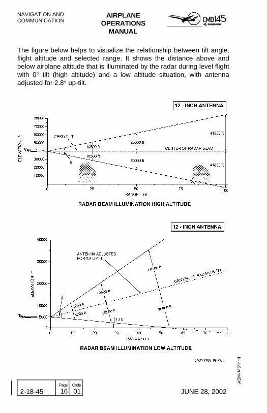
NAVIGATION ANDCOMMUNICATION
AIRPLANEOPERATIONS
MANUAL
2-18-45 Page
16 Code
01 JUNE 28, 2002
The figure below helps to visualize the relationship between tilt angle,flight altitude and selected range. It shows the distance above andbelow airplane altitude that is illuminated by the radar during level flightwith 0° tilt (high altitude) and a low altitude situation, with antennaadjusted for 2.8° up-tilt.
AIRPLANEOPERATIONS
MANUAL
NAVIGATION ANDCOMMUNICATION
JUNE 28, 2002 2-18-45 Page
17 Code
01
ALTITUDE COMPENSATED TILT (ACT) (P-880 MODEL ONLY)
In ACT, the antenna tilt is automatically adjusted with regard to theselected range and airplane altitude. ACT adjusts the tilt to show a fewground targets at the edge of the display. The TILT knob can be usedfor fixed offset corrections of up to 2°.
NOTE: Proper tilt management demands that tilt be changedcontinuously, even in airplanes equipped with ACT.
SLAVE (SLV) (DUAL CONTROL PANEL ONLY)
For airplanes equipped with dual weather radar control panels, onecontroller can be slaved to the other by selecting OFF on that controlleronly. This condition is annunciated by the illumination of SLV on thecontrol panel. The slave mode allows one controller to set the radarmodes for both sides. In the slave mode, the PFDs and MFDs radarinformation are identical and simultaneously updated.
NOTE: In the slaved condition, both control panels must be set to offbefore the radar system turns off.

NAVIGATION ANDCOMMUNICATION
AIRPLANEOPERATIONS
MANUAL
2-18-45 Page
18 Code
01 JUNE 28, 2002
RADOME
The radome is the primary factor behind degraded weather radarperformance. The problems affecting the radome are as follows:- A water film over the radome’s surface when flying in rain.
- Greased radome.
- Cracked radome.
- Holes caused by lightning strike/electrostatic discharges.
- Excessive application of antistatic paint.
Water Film Over The Radome’s Surface: When flying in rain, thereis indication that at some specific altitudes and speeds a water film isformed on the radome, altering the weather radar indications. Theradar display may disappear or turn red. To avoid this problem, there isa hydrophobic coating product named Cytonix that can be applied tothe radome surface.
Greased Radome: The presence of grease or dirt over the radome’ssurface also impairs radar transmission. These should be reportedimmediately to maintenance personnel for cleaning or correctiveaction.
Electrostatic Discharges: Static electricity influences radarperformance. The right bonding is necessary. Bonding is accomplishedthrough two metallic meshes that link the radome’s metallic bulkhead(diverters) to the airplane’s airframe. It is important to make sure thatthey are in good condition and not painted. If both the metallic meshesand screws are painted, this will isolate the static power generated inthe radome, resulting in electrical discharges that will follow towardsthe radar antenna and/or generate noise in the audio system.
Cracked Radome: Small holes caused by electrostatic discharges,minor damage to structure or paint can cause water infiltration in theradome’s honeycomb composite structure. It can result in significantradar signal attenuation, distortion and in some cases, can cause darkspots on the radar screen.
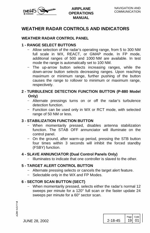
AIRPLANEOPERATIONS
MANUAL
NAVIGATION ANDCOMMUNICATION
JUNE 28, 2002 2-18-45 Page
19 Code
01
WEATHER RADAR CONTROLS AND INDICATORS
WEATHER RADAR CONTROL PANEL
1 - RANGE SELECT BUTTONS − Allow selection of the radar’s operating range, from 5 to 300 NM
full scale in WX, REACT, or GMAP mode. In FP mode,additional ranges of 500 and 1000 NM are available. In testmode the range is automatically set to 100 NM.
− The up-arrow button selects increasing ranges, while thedown-arrow button selects decreasing ranges. Upon reachingmaximum or minimum range, further pushing of the buttoncauses the range to rollover to minimum or maximum range,respectively.
2 - TURBULENCE DETECTION FUNCTION BUTTON (P-880 ModelOnly)− Alternate pressings turns on or off the radar’s turbulence
detection function.− Function can be used only in WX or RCT mode, with selected
range of 50 NM or less.
3 - STABILIZATION FUNCTION BUTTON− When momentarily pressed, disables antenna stabilization
function. The STAB OFF annunciator will illuminate on thecontrol panel.
− On the ground, after warm-up period, pressing the STB buttonfour times within 3 seconds will inhibit the forced standby(FSBY) function.
4 - SLAVE ANNUNCIATOR (Dual Control Panels Only)− Illuminates to indicate that one controller is slaved to the other.
5 - TARGET ALERT CONTROL BUTTON− Alternate pressing selects or cancels the target alert feature.− Selectable only in the WX and FP Modes.
6 - SECTOR SCAN BUTTON (SECT)− When momentarily pressed, selects either the radar’s normal 12
sweeps per minute for a 120° full scan or the faster update 24sweeps per minute for a 60° sector scan.

NAVIGATION ANDCOMMUNICATION
AIRPLANEOPERATIONS
MANUAL
2-18-45 Page
20 Code
01 JUNE 28, 2002
7 - ANTENNA TILT CONTROL KNOB− The TILT knob is a rotary control that allows manual control of
the antenna’s tilt angle. Clockwise rotation tilts the beam upward0° to +15°. Counter-clockwise rotation tilts beam downward 0° to–15°. A digital readout of the antenna tilt angle is displayed onthe MFD.
− The range between +5° and -5° is expanded for setting ease.
ALTITUDE COMPENSATED TILT (PULL ACT) (P-880 Model Only)− Pulling out the TILT knob activates the auto tilt control, which
automatically readjusts tilt between ± 2° based on changes inbarometric altitude and/or selected range.
8 - RADAR MODES CONTROL KNOB OFF- Turns off the weather radar. SBY - Selects the weather radar standby operating mode. WX - Selects the weather radar detection operating mode. RCT- Selects the REACT function (P-880 Model only). GMAP - Selects the weather radar ground mapping operatingmode. FP - Selects the weather radar flight plan operating mode. TST - Selects the weather radar test mode.
9 - GAIN CONTROL KNOB− Allows receiver gain control.− When pushed in, receiver gain is preset and calibrated. Rotary
function of the GAIN knob is disabled− When pulled out, sets receiver gain to variable (VAR) mode.
10 - RAIN ECHO ATTENUATION COMPENSATION TECHNIQUEFUNCTION BUTTON (P-660 Model Only)
− When pressed (momentarily), enables the REACT.− REACT is always selected in test mode.− REACT is available in all modes except MAP.

AIRPLANEOPERATIONS
MANUAL
NAVIGATION ANDCOMMUNICATION
JUNE 28, 2002 2-18-45 Page
21 Code
01
WEATHER RADAR CONTROL PANEL

NAVIGATION ANDCOMMUNICATION
AIRPLANEOPERATIONS
MANUAL
2-18-45 Page
22 Code
01 JUNE 28, 2002
MFD BEZEL PANEL
1 - WEATHER RADAR DISPLAY SELECTOR BUTTON− − Alternate pressing of the weather radar display selector button
allows the weather radar to be displayed or removed from theMFD. Control of all other weather radar functions isaccomplished by the radar control panel. When the weatherradar is selected, the WX label on the MFD menu, above thisbutton, will be highlighted by a white box.
− − The weather radar can only be selected for display in mapformat. If the weather radar is selected with plan format alreadyselected on the MFD, it will force the display to revert to mapformat.
2 - MAP/PLAN FORMATS CONTROL BUTTON− Alternate pressing of the map/plan formats control button will
cause the MFD to toggle between map and plan formats. Awhite box around will highlight the selected MFD format.
− If the weather radar is displayed on the MFD and the plan formatis selected, the weather radar will be removed from the display.However, if the MFD map format is selected again, the weatherradar display will be restored on the MFD.

AIRPLANEOPERATIONS
MANUAL
NAVIGATION ANDCOMMUNICATION
JUNE 28, 2002 2-18-45 Page
23 Code
01
MFD BEZEL PANEL
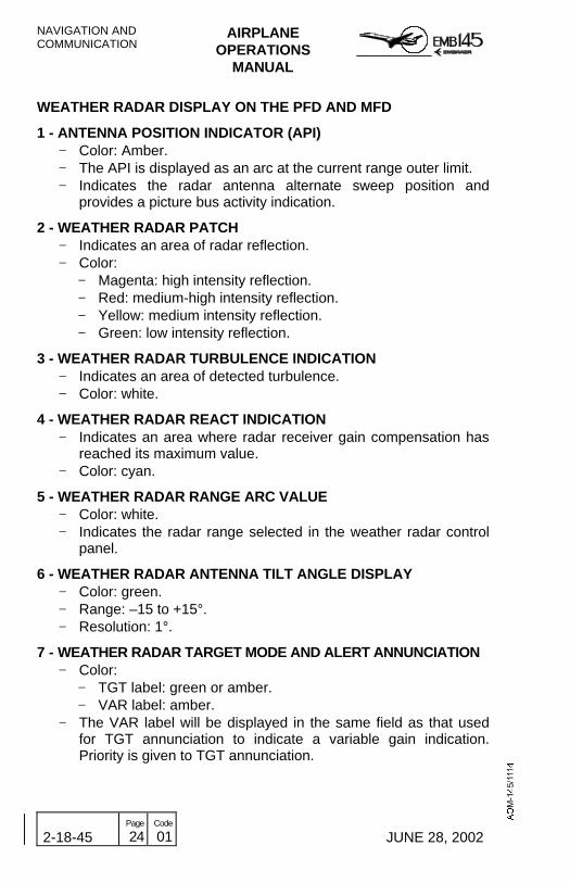
NAVIGATION ANDCOMMUNICATION
AIRPLANEOPERATIONS
MANUAL
2-18-45 Page
24 Code
01 JUNE 28, 2002
WEATHER RADAR DISPLAY ON THE PFD AND MFD
1 - ANTENNA POSITION INDICATOR (API)− Color: Amber.− The API is displayed as an arc at the current range outer limit.− Indicates the radar antenna alternate sweep position and
provides a picture bus activity indication.
2 - WEATHER RADAR PATCH− Indicates an area of radar reflection.− Color:
− Magenta: high intensity reflection.− Red: medium-high intensity reflection.− Yellow: medium intensity reflection.− Green: low intensity reflection.
3 - WEATHER RADAR TURBULENCE INDICATION− Indicates an area of detected turbulence.− Color: white.
4 - WEATHER RADAR REACT INDICATION− Indicates an area where radar receiver gain compensation has
reached its maximum value.− Color: cyan.
5 - WEATHER RADAR RANGE ARC VALUE− Color: white.− Indicates the radar range selected in the weather radar control
panel.
6 - WEATHER RADAR ANTENNA TILT ANGLE DISPLAY− Color: green.− Range: –15 to +15°.− Resolution: 1°.
7 - WEATHER RADAR TARGET MODE AND ALERT ANNUNCIATION− Color:
− TGT label: green or amber.− VAR label: amber.
− The VAR label will be displayed in the same field as that usedfor TGT annunciation to indicate a variable gain indication.Priority is given to TGT annunciation.

AIRPLANEOPERATIONS
MANUAL
NAVIGATION ANDCOMMUNICATION
JUNE 28, 2002 2-18-45 Page
25 Code
01
8 - WEATHER RADAR MODES ANNUNCIATION DISPLAY− Indicates the selected mode in the weather radar control panel.
DISPLAY MODE DESCRIPTION
ANNUNCIATION COLOR
STAB AMBER Stabilization off.TGT GREEN Target alert enable.TGT AMBER Target alert enable and level 3
WX return detected in the forward15° of antenna scan.
VAR AMBER Variable gain.WX GREEN Normal WX ON and selected for
display.WX AMBER Invalid WX control bus.TX GREEN WX is transmitting but not
selected for display, or in STBYor FSTBY.
TX AMBER WX is transmitting and weight onwheels indicates on ground, butnot selected for display, or inSTBY and FSTBY.
WAIT GREEN Warm up period of approximately40 to 100 seconds.
STBY GREEN Normal standby.FSBY GREEN Forced standby.TEST GREEN Test mode and no faults.FAIL AMBER Test mode and faults.RCT GREEN Normal WX with REACT.FPLN GREEN Flight plan mode.GMAP GREEN Ground map mode.GCR AMBER Normal WX with ground clutter
reduction.R/T GREEN WX with REACT and turbulence.WX/T GREEN Normal WX with turbulence.

NAVIGATION ANDCOMMUNICATION
AIRPLANEOPERATIONS
MANUAL
2-18-45 Page
26 Code
01 JUNE 28, 2002
WEATHER RADAR DISPLAY ON PFD

AIRPLANEOPERATIONS
MANUAL
NAVIGATION ANDCOMMUNICATION
JUNE 28, 2002 2-18-45 Page
27 Code
01
WEATHER RADAR DISPLAY ON MFD

NAVIGATION ANDCOMMUNICATION
AIRPLANEOPERATIONS
MANUAL
2-18-45 Page
28 Code
01 JUNE 28, 2002
THIS PAGEIS LEFT BLANK INTENTIONALLY

AIRPLANEOPERATIONS
MANUAL
NAVIGATION ANDCOMMUNICATION
REVISION 26 2-18-85 Page
1 Code
01
PRECISION AREA NAVIGATION (P-RNAV)P-RNAV defines European RNAV operations, which satisfy a requiredtrack-keeping accuracy of ±1 NM for at least 95% of the flight time,path coding in accordance with ARINC 424 (or an equivalentstandard), and the automatic selection, verification and, whereappropriate, de-selection of navigation aids.P-RNAV operations determines aircraft position in the horizontal planeusing inputs from the following types of positioning sensors (in nospecific order of priority):
− Distance Measurement Equipment (DME) giving measurementsfrom two or more ground station (DME/DME);
− VHF Omni-directional Range (VOR) with a co-located DME(VOR/DME), where it is identified as meeting the requirements ofthe procedures;
− Global Navigation Satellite System (GNSS);− Inertial Navigation System (INS) or Inertial Reference System (IRS),
with automatic updating from suitable radio based navigationequipment.
P-RNAV is used for departures, arrivals and approach (FAWP - FinalApproach Waypoint), and not used on final approach, i.e. from FAWPto RWY and missed approach.
LIMITATIONS
− For P-RNAV operations in terminal airspace, obstacle clearanceprotection, up to the FAWP, will assume that aircraft comply withthe P-RNAV accuracy requirements;
− Obstacle clearance altitude has been based upon the infrastructuregiving the poorest precision;
− The minimum flight crew are 2 Pilots;− It is not permissible to use, for any period of time, data from an
inertial system as the only means of positioning;− The system must display essential information in the Pilot’s primary
field of view such as:− Lateral Deviation;− TO/FROM waypoints;− Failure flag (failure of P-RNAV system);

NAVIGATION ANDCOMMUNICATION
AIRPLANEOPERATIONS
MANUAL
2-18-85 Page
2 Code
01 REVISION 26
− Unless automatic updating of the actual departure point is provided,the flight crew must ensure initialization on the runway either meansof a manual runway threshold or intersection update, as applicable.This is to preclude any inappropriate or inadvertent position shiftafter take-off;
− Where reliance is placed on the use of radar to assist contingencyprocedures, its performance has been shown to be adequate for thatpurpose, and the requirement for a radar service is identified in theAIP
− P-RNAV operations must use FMS to control all lateral navigationfunctions. For FMS limitations, refer to Section 1-01-60 (Limitations,System: FMS) of AOM.
− The system must have means to display to the flight crew thefollowing items:
− The active (TO) waypoint and distance/bearing to this point;− Ground speed or time to the active (TO) waypoint;− Automatic tuning of VOR and DME navigation aids used for
position updating together with the capability to inhibitindividual navigation aids;
− RNAV system failure;− Alternate means of displaying navigation information,
sufficient to perform cross-checks procedures.

AIRPLANEOPERATIONS
MANUAL
NAVIGATION ANDCOMMUNICATION
REVISION 26 2-18-85 Page
3 Code
01
P-RNAV SYSTEM
NAVIGATION ANDCOMMUNICATION
AIRPLANEOPERATIONS
MANUAL
2-18-85 Page
4 Code
01 REVISION 26
NORMAL PROCEDURES
− Verify NOTAM (Notice to Airman) for non-available P-RNAVprocedure, if navigational aids, identified in the AIP as criticalfor a specific P-RNAV procedure, are not available;
− Use phraseology appropriate to P-RNAV operations;− When the VOR or DME is not available or shutdown, the flight
crew have to inhibit the navigation aid from the automaticselection process;
− The flight crew must notify ATC of any problem with the RNAVsystem that results in loss of the required navigation capability,together with the proposed course of action;
− Discrepancies that invalidate a procedure must be reported tothe navigation database supplier and affected procedures mustbe prohibited by an operators notice to its flight crew.
PRE-FLIGHT PLANNING
− Verify the required navigation aids critical to the operation ofspecific procedure, and if they are identified in the AIP(Aeronautical Information Publication) and on the relevantcharts;
− Check availability of the navigation infrastructure and onboardequipment for the period of intended operation;
− The navigation database must be appropriate for the region ofthe intended operation and must include the navigation aids,waypoints, and coded terminal airspace procedures for thedeparture, arrival and alternate airfields;
− When specified in the AIP that dual P-RNAV procedure arerequired for specific terminal P-RNAV procedure, theavailability of dual P-RNAV system must be confirmed;
− If a stand-alone GPS is to be used for P-RNAV, the availabilityof RAIM must be confirmed;
DEPARTURE
− Both Pilots must verify if the navigation database is current andif aircraft position has been entered correctly;
− The PNF (Pilot Not Flying) must verify the desired path and theaircraft position relative to the path;
− The active flight plan should be checked by comparing thecharts with the MAP display and the MCDU;

AIRPLANEOPERATIONS
MANUAL
NAVIGATION ANDCOMMUNICATION
REVISION 26 2-18-85 Page
5 Code
01
− A procedure shall not be used if doubt exists as to the validityof the procedure in the navigation database;
− The creation of new waypoints by manual entry into the RNAVsystem by the flight crew is not permitted;
− Route modifications in the terminal area may take form of radarheadings or direct to clearances;
− Prior to take off, the flight crew must verify that the R-NAVsystem is available and operating correctly and, whereapplicable, the correct airport and runway data have beenloaded;
− Unless automatic updating of the actual departure point isprovided, the flight crew must ensure initialization on therunway either by means of a manual runway threshold orintersection update, as applicable. This is to preclude anyinappropriate or inadvertent position shift after take-off. WhereGNSS is used, the signal must be acquired before the take-offroll commences and GNSS position may be used in place ofthe runway update;
− During the procedure and where feasible, flight progress shouldbe monitored for navigational reasonableness, by cross-checks,with conventional aids using the primary displays in conjunctionwith the MCDU.
− When automatic update for departure is not available, theprocedure should be flown by conventional navigation means.A transition to the P-RNAV structure should be made at thepoint where the aircraft has entered DME/DME coverage andhas had sufficient time to achieve an adequate input. If aprocedure is designed to be started conventionally, then thelatest point of transition to the P-RNAV structure will be markedon the charts. If a Pilot elects to start a P-RNAV procedureusing conventional methods, there will not be any indication onthe charts of the transition point to the P-RNAV structure.
ARRIVAL
Prior to the arrival phase, the flight crew should verify that the correctterminal procedure has been loaded. The active flight plan should bechecked by comparing the charts with the MAP display and theMCDU. This includes confirmation of the waypoint sequence,reasonableness of track angles and distances, any altitude or speedconstraints, and, where possible, which waypoints are fly-by and whichare fly-over.

NAVIGATION ANDCOMMUNICATION
AIRPLANEOPERATIONS
MANUAL
2-18-85 Page
6 Code
01 REVISION 26
− If required by procedure, a check will need to be made toconfirm that updating will exclude a particular navigation aid. Aprocedure shall not be used if doubt exists as to the procedurein the navigation database;
− Where the contingency to revert to a conventional arrivalprocedure the flight crew must make the necessary preparation;
− During the procedure and where feasible, flight progress shouldbe monitored for navigational reasonableness by cross-checkswith conventional navigation aids using the primary displays inconjunction with the MCDU. In particular, for a VOR/DMERNAV procedure, the reference VOR/DME used for theconstruction of the procedure must be displayed and checkedby the flight crew. For RNAV systems without GNSS updating,a navigation reasonableness check is required during thedescent phase before reaching the Initial Approach Waypoint(IAWP). For GNSS based systems, absence of an integrityalarm is considered sufficient. If the check fails, a conventionalprocedure must then be flown;
− Route modifications in the terminal area may take the form ofradar headings or direct to clearances and the flight crew mustbe capable of reacting in a timely fashion. This may include theinsertion of tactical waypoints loaded from the database.Manual entry or modification by the flight crew of a loadedprocedure, using temporary waypoints or fixes not provided inthe data base, is not permitted;
− Although a particular method is not mandated, any publishedaltitude or speed constraints must be observed.
CONTINGENCY PROCEDURES
− The flight crew must notify ATC of any problem with the RNAVsystem that results in the loss of required navigation capability,together with the proposed course of action;
− In the event of communication failure, the crew should continuewith the RNAV procedure in accordance with the published lostcommunication procedure;
− In case of loss of P-RNAV capability, the flight crew shouldnavigate using an alternative means of navigation. Thealternate means need not be an RNAV system;
− Cautions and warnings for the following conditions:− Failure of the RNAV system components including those
affecting flight technical error;

AIRPLANEOPERATIONS
MANUAL
NAVIGATION ANDCOMMUNICATION
REVISION 26 2-18-85 Page
7 Code
01
− Flight director – discontinue the P-RNAV procedurefollowing the approved missed approach procedure or iffeasible revert to a conventional or IRS procedure andinform ATC;
− Automatic Flight – continue the approach using manualflight, and if the flight path cannot be followed perform aapproved missed approach procedure and inform ATC;
− Multiple system failures – If a multiple system failures occurssuch as affecting GNSS, Flight Director, and any other used forP-RNAV procedure, a missed approach procedure must beperformed and inform ATC;
− Failure of navigation sensors - discontinue the P-RNAVprocedure following the approved missed approach procedureor if feasible revert to a conventional or IRS procedure andinform ATC.
INCIDENT REPORTING
Significant incidents associated with the operation of the aircraft whichaffect or could affect the safety of RNAV operations, need to bereported on the appropriate report manifest.Specific examples may include:
− Aircraft system malfunctions during P-RNAV operations whichlead to:− Navigations errors not associated with transitions between
different navigation modes;− Significant navigation errors attributed to incorrect data or a
navigation database coding error;− Unexpected deviations in lateral or vertical flight path not
cause by Pilot input;− Significant misleading information without a failure warning;− Total loss or multiple navigation equipment failure;
− Problems with ground navigational facilities leading tosignificant navigational errors not associated with transitionsbetween different navigation modes.
NAVIGATION ANDCOMMUNICATION
AIRPLANEOPERATIONS
MANUAL
2-18-85 Page
8 Code
01 REVISION 26
THIS PAGE IS LEFT BLANK INTENTIONALLY