Embed Size (px)
Citation preview

GUIDELINES FOR COMMUNICATION, NAVIGATION, SURVEILLANCE, AND AIR TRAFFIC MANAGEMENT (CNS/ATM)
SYSTEMS SOFTWARE INTEGRITY ASSURANCE
This document is the exclusive intellectual and commercial property of EUROCAE.
It is presently commercialised by EUROCAE.
This electronic copy is delivered to your company/organisation for internal use exclusively.
In no case it may be re-sold, or hired, lent or exchanged outside your company.
ED-109 March 2002
The European Organisation for Civil Aviation EquipmentL’Organisation Européenne pour l’Equipement de l’Aviation Civile
17, rue Hamelin Tel : 33 1 45 05 71 88 75783 PARIS, Cedex 16, France Fax : 33 1 45 05 72 30 Web Site : www.eurocae.org Email : [email protected]
GUIDELINES FOR COMMUNICATION, NAVIGATION, SURVEILLANCE, AND AIR TRAFFIC MANAGEMENT (CNS/ATM)
SYSTEMS SOFTWARE INTEGRITY ASSURANCE
This document is the exclusive intellectual and commercial property of EUROCAE.
It is presently commercialised by EUROCAE.
This electronic copy is delivered to your company/organisation for internal use exclusively.
In no case it may be re-sold, or hired, lent or exchanged outside your company.
ED-109 March 2002

© EUROCAE, 2002
i
FOREWORD
1. This document, jointly prepared by EUROCAE Working Group 52 and RTCA Special Committee 190, was accepted by the Council of EUROCAE on March 2002.
2. EUROCAE is an international non-profit making organisation. Membership is open to manufacturers and users in Europe of equipment for aeronautics, national civil aviation administrations, trade association and, under certain conditions, non-European members. Its work programme is principally directed to the preparation of performance specifications and guidance documents for civil aviation equipment, for adoption and use at European and world-wide levels.
3. The findings of EUROCAE are resolved after discussion among its members and in cooperation with the RTCA Inc., Washington DC, and/or the Society of Automotive Engineers (SAE), Warrendale, PA, USA, through their appropriate committees.
4. EUROCAE Performance Specifications and Guidance Documents are recommendations only; EUROCAE is not an official body of the European Governments. Its recommendations therefore are not valid as statements of official policy unless adopted by a particular government or conference of governments.
5. Copies of this document may be obtained from:
EUROCAE
17 rue Hamelin 75783 PARIS Cedex 16
FRANCE
Phone: +33 1 4505 7188 Fax: +33 1 4505 7230
E-mail: [email protected] Web Site: www.eurocae.org

© EUROCAE, 2002
ii
TABLE OF CONTENTS
FOREWORD ............................................................................................................................. i
CHAPTER 1 INTRODUCTION ................................................................................................. 1
1.1 Purpose................................................................................................................ 1
1.2 Scope................................................................................................................... 1
1.3 Relationship to Other Documents........................................................................ 1
1.4 Document Overview ............................................................................................ 2
1.5 How to Use This Document ................................................................................. 3
CHAPTER 2 SYSTEM ASPECTS RELATING TO CNS/ATM SOFTWARE DEVELOPMENT 4
2.1 Assurance Levels ................................................................................................ 4
2.2 Additional System Considerations....................................................................... 5
CHAPTER 3 OBJECTIVES FOR CNS/ATM SYSTEMS .......................................................... 7
3.1 Software Planning Process Objectives (Table A-1) ............................................ 9
3.2 Software Development Process Objectives (Table A-2) ..................................... 10
3.3 Verification of Outputs of Software Requirements Process Objectives (Table A-3) ......................................................................................... 11
3.4 Verification of Outputs of Software Design Process Objectives (Table A-4) ........................................................................................................... 12
3.5 Verification of Outputs of Software Coding and Integration Process Objectives (Table A-5) ......................................................................................... 14
3.6 Testing of Outputs of Integration Process Objectives (Table A-6) ...................... 15
3.7 Verification of Verification Process Results Objectives (Table A-7) .................... 16
3.8 Software Configuration Management (SCM) Process Objectives (Table A-8) ........................................................................................................... 17
3.9 Software Quality Assurance (SQA) Process Objectives (Table A-9) .................. 18
3.10 Software Approval Process Objectives (Table A-10) .......................................... 19
CHAPTER 4 ADDITIONAL CONSIDERATIONS FOR CNS/ATM SOFTWARE ...................... 20
4.1 Commercial Off-The-Shelf (COTS) Software ...................................................... 20
4.2 Adaptation Data Process..................................................................................... 30

© EUROCAE, 2002
iii
CHAPTER 5 CNS/ATM-SPECIFIC LIFE CYCLE DATA .......................................................... 32
5.1 Plan for Software Aspects of Approval (PSAA)................................................... 32
5.2 Adaptation Data ................................................................................................... 32
5.3 COTS Software Life Cycle Data .......................................................................... 32
APPENDIX A ACRONYMS AND GLOSSARY OF TERMS....................................................... 33
APPENDIX B BACKGROUND OF DOCUMENT ED-109/DO-278 ............................................ 36
APPENDIX C COMMITTEE MEMBERSHIP.............................................................................. 39
APPENDIX D IMPROVEMENT SUGGESTION FORM ............................................................. 44

© EUROCAE, 2002
1
CHAPTER 1
INTRODUCTION
The implementation of Communication, Navigation, Surveillance, and Air Traffic Management (CNS/ATM) systems has resulted in increased interdependence of systems providing Air Traffic Services (ATS) and systems onboard aircraft. CNS/ATM systems include ground, airborne, and space-based systems. In order for these systems to perform their intended function while providing an acceptable level of safety, there is a need to define consistent and/or equivalent means of providing integrity assurance for the software in these systems.
1.1 PURPOSE
This document provides guidelines for the assurance of software contained in non-airborne CNS/ATM systems. ED-12B/DO-178B, Software Considerations in Airborne Systems and Equipment Certification, defines a set of objectives that are recommended to establish assurance that airborne software has the integrity needed for use in a safety-related application. These objectives have been reviewed, and in some cases, modified for application to non-airborne CNS/ATM systems. This document is intended to be an interpretive guide for the application of ED-12B/DO-178B guidance to non-airborne CNS/ATM systems.
1.2 SCOPE
This guidance applies to software contained in CNS/ATM systems used in ground or space-based applications shown by a system safety assessment process to affect the safety of aircraft occupants or airframe in its operational environment. The assurance of software resident within the airframe boundaries, including CNS/ATM-related equipment, is addressed by ED-12B/DO-178B.
A description of the safety assessment process is not included in this document. Information on such assessments is available from other industry sources and in related regulatory guidance. Likewise, a complete description of the system life cycle processes, including system validation, as well as CNS/ATM systems approval, is not intended. This guidance is not intended to be a development standard nor a process document.
It should be noted that additional objectives and evidence may be needed for certain elements of CNS/ATM systems for reasons that are beyond the scope of this document (e.g., additional requirements due to the difficulty in servicing satellite systems).
1.3 RELATIONSHIP TO OTHER DOCUMENTS
This document is intended to be used in conjunction with ED-12B/DO-178B and related explanatory material found in ED-94B/DO-248B, Final Report for Clarification of ED-12B/DO-178B ‘Software Considerations in Airborne Systems and Equipment Certification’. Using ED-12B/DO-178B as a basis for this document is intentional and is intended to produce an equivalent level of assurance for the integrity of software in both non-airborne and airborne CNS/ATM systems. The regulatory or Approval Authorities may publish additional guidance on the interpretation of ED-12B/DO-178B or ED-109/DO-278 for both the airborne and non-airborne communities. Such guidance should be consulted, as needed.

© EUROCAE, 2002
2
During the development of this document, various national and international software integrity assurance standards were reviewed. While the means of compliance may differ, no incompatibilities were identified with these standards. These other standards are available through national and international agencies. In some communities, compliance with these standards may be required. However, it is outside the scope of this document to invoke specific national or international standards, or to propose a means by which these standards might be used as an alternative or supplement to this document.
1.4 DOCUMENT OVERVIEW
DO-278/ED-109 contains five sections and four appendices, as described below:
! Section 1 provides introductory material.
! Section 2 addresses the system aspects relating to the development of software in CNS/AM systems. Section 2.1 defines software assurance levels and their relationship to software levels defined in ED-12B/DO-178B. Section 2.2 discusses additional system considerations applicable specifically to CNS/ATM systems.
! Section 3 contains the objective tables copied from ED-12B/DO-178B, Annex A. These objective tables were modified, as appropriate, for CNS/ATM systems. These tables should be used instead of Annex A in ED-12B/DO-178B and include a new assurance level. Clarifications and additions to the ED-12B/DO-178B tables are identified in the “Considerations” sections immediately following each table. Examples of the types of clarifications and additions noted are:
1. Deleted objectives,
2. Added objectives (new objective for one or more levels),
3. Deleted and modified data items,
4. Examples to aid in understanding,
5. References to additional information, and
6. Terminology explanations.
! Section 4 discusses additional considerations, including guidance for Commercial Off-The-Shelf (COTS) software and adaptation data.
! Section 5 describes additional software life cycle data applicable to software developed for CNS/ATM systems.
! Appendix A provides a list of acronyms and a glossary. Glossary entries are either additional to or slightly different from those included in ED-12B/DO-178B. The terms are specific to CNS/ATM systems.
! Appendix B provides background information on this document.
! Appendix C provides a list of participants who contributed to this document.
! Appendix D provides a comment form for suggesting improvements to this document.

© EUROCAE, 2002
3
1.5 HOW TO USE THIS DOCUMENT
As noted above, this document is intended to be used with ED-12B/DO-178B. Sections 4 through 9 of ED-12B/DO-178B provide a description and guidance of objectives and activities for airborne software assurance for the most stringent software level. A series of tables are provided in Annex A of ED-12B/DO-178B that modulate the level of assurance recommended for software of lower levels. References in the tables point back to the appropriate definition of the objective, to the associated activities used to satisfy the objective, and to the data items produced to provide evidence of the activity. ED-94B/DO-248B provides additional clarifications and explanations for the contents of ED-12B/DO-178B.
When reviewing ED-12B/DO-178B for CNS/ATM systems, the following terms specific to the airborne community should be replaced as follows:
! “Airborne” with “CNS/ATM System”
! “Certification” with “Approval”
! “Applicant” with “Supplier”
! “Airworthiness requirements” with “Applicable Approval requirements”
! “Certification liaison process” with “Approval process”
! “Plan for Software Aspects of Certification” (PSAC) with “Plan for Software Aspects of Approval” (PSAA)
A suggested approach for using this material is to:
1. Read Sections 1, 2 (except 2.2), 3, and 12 of ED-12B/DO-178B.
2. Read this document.
3. Reference Sections 4 through 9 of ED-12B/DO-178B for descriptions of the individual objectives and activities not covered in this document.
4. Reference Section 11 of ED-12B/DO-178B for descriptions of the software life cycle data not covered in this document.
5. Reference ED-12B/DO-178B glossary for definitions of terms not defined in this document.
6. Reference ED-94B/DO-248B for any Frequently Asked Questions (FAQs), Discussion Papers (DPs), and errata references.
Text appearing in Sections 3 through 5 and the glossary of this document is normative. Text in Sections 1 and 2 and the Appendices B through D, as well as any notes, should be considered informative only. In cases where examples are used to indicate how the guidelines might be applied, either graphically or through narrative, the examples are not to be interpreted as the preferred method. Lists of items should not be construed as all-inclusive.
© EUROCAE, 2002
4
CHAPTER 2
SYSTEM ASPECTS RELATING TO CNS/ATM SOFTWARE DEVELOPMENT
2.1 ASSURANCE LEVELS
The results of a safety assessment process should be used to establish the appropriate software assurance level for all elements of the CNS/ATM system. The description of the safety assessment process is outside the scope of this document; however, the software assurance levels assigned by the safety assessment process are described below:
! Assurance level 1 (AL1) is associated with and equivalent to software level A of ED-12B/DO-178B. AL1 corresponds to non-airborne software that should satisfy the most stringent objectives.
! AL2, AL3, and AL5 are associated with and equivalent to airborne software levels B, C, and D, respectively, of ED-12B/DO-178B. AL2, AL3, and AL5 correspond to non-airborne software that should satisfy successively less stringent objectives as indicated in Section 3 of this document.
! AL6 is associated with and equivalent to airborne software level E. AL6 applies to software whose anomalous behaviour, as shown by a safety assessment process, cannot cause or contribute to a failure of system function with a safety impact. Once software has been confirmed as AL6 by a safety assessment, no further guidelines of this document apply.
! AL4 is not associated with or equivalent to any airborne software level.
NOTE: AL4 was developed to account for certain CNS/ATM systems where AL3 was too stringent and AL5 was too lenient. This level has a direct correlation with some regulatory requirements proposed for use within the aviation community.
It should be noted that alternative approaches exist for identifying safety-related requirements to the software process. The user of this document should identify the mechanism for capturing safety-related requirements that may affect the software assurance needed and should obtain the necessary agreement and approval from the Approval Authority.
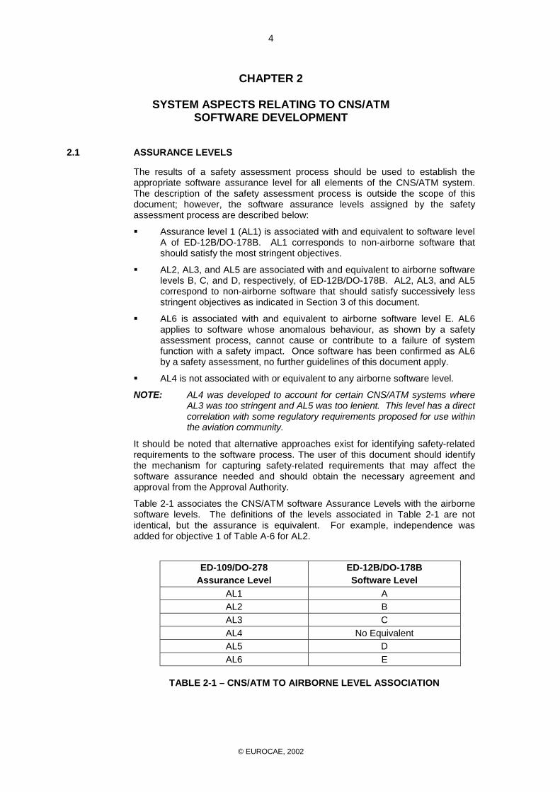
Table 2-1 associates the CNS/ATM software Assurance Levels with the airborne software levels. The definitions of the levels associated in Table 2-1 are not identical, but the assurance is equivalent. For example, independence was added for objective 1 of Table A-6 for AL2.
ED-109/DO-278
Assurance Level ED-12B/DO-178B Software Level
AL1 A AL2 B AL3 C AL4 No Equivalent AL5 D AL6 E
TABLE 2-1 – CNS/ATM TO AIRBORNE LEVEL ASSOCIATION
© EUROCAE, 2002
5
2.2 ADDITIONAL SYSTEM CONSIDERATIONS
The definition of “system” is broad enough to specify a single piece of hardware with embedded software, multiple hardware items with common software, or multiple hardware items with multiple software components that work together for a common function. This section introduces system considerations in addition to those provided in ED-12B/DO-178B, Section 2 (except 2.2).
2.2.1 Architectural Considerations
A common practice for reducing safety risk in system design is to isolate functionality that may cause or contribute to a system failure. Architectural techniques (e.g., isolation, command/monitoring, dissimilarity with comparators) can be used to reduce the amount of software that needs to be produced to the more stringent assurance levels.
2.2.2 System Communication
As different hardware and software components communicate with each other, faults in one component have the potential to propagate to other components. Safety analyses should consider data paths through a system to ensure a function of one assurance level does not corrupt data or associated functions of a higher assurance level. CNS/ATM systems development should specifically address fault propagation and data paths.
2.2.3 Security
Security requirements should be addressed for CNS/ATM systems. Potential conflicts between security and safety requirements should be resolved at the system level. The resultant requirements to be allocated to software should be defined.
2.2.4 Adaptability
The safety considerations of system adaptation should be addressed for CNS/ATM systems. The adaptation data process is detailed in Section 4.2 of this document.
2.2.5 Cutover (Hot Swapping)
CNS/ATM systems are sometimes required to run 24 hours per day. Some CNS/ATM systems need provisions for replacing components or software while the system is operational. This approach is commonly referred to as “cutover” or “hot swapping”. Cutover considerations include (but are not limited to):
! Mechanisms for installing and hot swapping software should ensure that appropriate availability and integrity levels are maintained.
! Assurance should be provided such that the safety objectives defined in a safety assessment process have not been compromised during or after cutover.

© EUROCAE, 2002
6
! After a swap, the ability to revert to the previous configuration should be provided.
! Compatibility with other system components and the appropriate software version should be maintained.
2.2.6 Post-Development Life Cycle
Users of CNS/ATM systems should address long term maintenance, spares, retirement, training, etc. While the guidance contained in this document primarily addresses the development of the software for CNS/ATM systems, this does not negate the need to address post-development maintenance and revision activities.

© EUROCAE, 2002
7
CHAPTER 3
OBJECTIVES FOR CNS/ATM SYSTEMS
This section provides guidelines for the software life cycle process objectives and outputs described by assurance level. Sections 3.1 through 3.10 include Tables A-1 through A-10. These tables reference the objectives and outputs of the software life cycle processes described in ED-12B/DO-178B as modified for application to non-airborne CNS/ATM systems.
Tables A-1 through A-10 in this section include:
! The objectives applicable for each assurance level (AL) with references to supporting text and output description.
NOTE 1: As discussed in Section 2, there are no objectives applicable to AL6.
NOTE 2: All references are to the text in ED-12B/DO-178B unless otherwise noted by an asterisk. If an asterisk is present, the reference is to this document.
! The requirements for independence, by assurance level, of the software life cycle process activities applicable to satisfy that process’ objectives.
NOTE: For equivalent levels (e.g., ED-12B/DO-178B software level A and ED-109/DO-278 AL1), objectives are the same with the exception of the addition of independence to three objectives that were added due to the scope of CNS/ATM systems. These objectives are objective 10 of Table A-4 and objectives 1 and 2 of Table A-6.
! The control category by assurance level for the data produced by the software life cycle process activities.
NOTE: The incorporation of two levels of data control is designed to allow the developer flexibility. Individual developers should define the attributes of the control categories (e.g., retention times, approval requirements, etc.) for themselves.
! The legend for entries in Tables A-1 to A-10 and Section 4.1.9 is equivalent to that used in ED-12B/DO-178B, as shown below:
Legend: # The objective should be satisfied with independence. $ The objective should be satisfied. Blank Satisfaction of objective is at supplier’s discretion.
1 Data satisfies the objectives of Control Category 1 (CC1)
2 Data satisfies the objectives of Control Category 2 (CC2)

© EUROCAE, 2002
8
Tables A-1 through A-10 should be read as follows:
! Column 1 (Objective Number) numbers the objectives listed in the table. These numbers correspond to those found in ED-12B/DO-178B wherever possible. Where objectives in ED-12B/DO-178B are no longer applicable or have been modified by the contents of this document, the objective is annotated.
! Column 2 (Objective Description) provides a short-form description of the objective.
! Column 3 (Objective Reference) provides a reference paragraph, either to ED-12B/DO-178B or to this document, in which further explanation of the objective may be found.
! Columns 4 through 8 (Applicability By Assurance Level) define the applicability of the objective and whether it should be satisfied with independence.
! Column 9 (Output Description) provides a short-form description of the output produced by complying with the objective.
! Column 10 (Output Reference) provides a reference paragraph, either to ED-12B/DO-178B or to this document, in which further explanation of the data item may be found.
! Columns 11 through 15 (Control Category By Assurance Level) define the level of configuration control that should be applied to the data item. This information should be used in conjunction with Table 7-1 of ED-12B/DO-178B.
Throughout the tables, references are provided to the Considerations section that immediately follows each table. These sections contain interpretive and explanatory text to supplement the content of each corresponding table.
NOTE: In the tables and the Considerations sections, the notation of “A-x,y” is used to number the considerations, which are further explained in the Considerations section following each table.

© EUROCAE, 2002
9
3.1 SOFTWARE PLANNING PROCESS OBJECTIVES (TABLE A-1)
The software planning process defines the means of producing software that will satisfy the system requirements and provide the level of assurance that is consistent with applicable requirements.
Objective Applicability By
Assurance Level
Output Control Category By Assurance Level
Description Ref. AL 1
AL 2
AL 3
AL 4
AL 5
Description Ref. AL 1
AL 2
AL 3
AL 4
AL 5
1 Software development and integral processes activities are defined. (A-1,1)
4.1a 4.3
$ $ $ $ $ Plan for Software Aspects of Approval (PSAA) (A-1,2)
5.1*
1
1 1 1 1
Software Development Plan (A-1,3)
11.2 1 1 2 2 2
Software Verification Plan
11.3 1 1 2 2 2
SCM Plan 11.4 1 1 2 2 2 SQA Plan 11.5 1 1 2 2 2
2 Transition criteria, inter-relationships and sequencing among processes are defined.
4.1b 4.3
$ $ $ $
3 Software life cycle environment is defined.
4.1c $ $ $ $
4 Additional considerations are addressed.
4.1d $ $ $ $ $
5 Software development standards are defined.
4.1e $ $ $ $ SW Requirements Standards SW Design Standards SW Code Standards
11.6 11.7 11.8
1 1 1
1 1 1
2 2 2
2 2 2
6 Software plans comply with this document.
4.1f 4.6
$ $ $ $ SQA Records Software Verification Results
11.19 11.14
2 2
2 2
2 2
2 2
7 Software plans are coordinated.
4.1g 4.6
$ $ $ $ SQA Records Software Verification Results
11.19 11.14
2 2
2 2
2 2
2 2
TABLE A-1 – SOFTWARE PLANNING PROCESS
(* Indicates reference to this document)

© EUROCAE, 2002
10
3.1.1 Considerations in Applying Table A-1 Objectives to CNS/ATM Systems
A-1,1: Part of the planning process involves determining how independence, as defined in ED-12B/DO-178B, will be demonstrated. In some cases, Approval Authorities may require a different definition of independence to be applied. This area should be negotiated between the supplier and the Approval Authority during the planning process.
A-1,2: The PSAA documents the plans and procedures associated with the approval process for software to be used in CNS/ATM systems. Reference Section 5.1 of this document for further details on the PSAA.
A-1,3: Since CNS/ATM systems may operate continuously and may have been in operation for many years, the software life cycle plans for these systems should include processes for software changes, technology upgrades, etc., specifically with respect to safety issues.
3.2 SOFTWARE DEVELOPMENT PROCESS OBJECTIVES (TABLE A-2)
The software development processes are performed as defined by the software planning process. The software development processes are: the software requirements process, the software design process, the software coding process, and the integration process.
Objective Applicability
By Assurance Level
Output Control Category
By Assurance Level
Description Ref. AL 1
AL 2
AL 3
AL 4
AL 5
Description Ref. AL 1
AL 2
AL 3
AL 4
AL 5
1 High-level requirements are developed. (A-2,1)
5.1.1a
$ $ $ $ $ Software Requirements Data
11.9 1 1 1 1 1
2 Derived high-level requirements are defined.
5.1.1b $ $ $ $ $ Software Requirements Data
11.9 1 1 1 1 1
3 Software architecture is developed. (A-2,2)
5.2.1a $ $ $ $ Design Description 11.10 1 1 2 2
4 Low-level requirements are developed. (A-2,2)
5.2.1a $ $ $ Design Description 11.10 1 1 2
5 Derived low-level requirements are defined. (A-2,2)
5.2.1b $ $ $ Design Description 11.10 1 1 2
6 Source Code is developed. (A-2,2)
5.3.1a $ $ $ Source Code 11.11 1 1 1
7 Executable Object Code is produced and integrated in the target computer. (A-2,3)
5.4.1a $ $ $ $ $ Executable Object Code
11.12 1 1 1 1 1
8 Adaptation Data and related processes are defined (when applicable). (A-2,4)
4.2* $ $ $ $ $ Adaptation Data 5.2* 1 1 1 1 2
TABLE A-2 – SOFTWARE DEVELOPMENT PROCESSES
(* Indicates reference to this document)

© EUROCAE, 2002
11
3.2.1 Considerations in Applying Table A-2 Objectives to CNS/ATM Systems
A-2,1: A margin for throughput (e.g., Input and Output (I/O) rate or Central Processing Unit (CPU) load) and memory usage should be identified where needed to meet CNS/ATM requirements.
A-2,2: Objectives 3 through 6 of Table A-2 indicate that compliance is not needed for AL5. This differs from ED-12B/DO-178B. The data items resulting from activities to satisfy these objectives do not need to be verified by other objectives; therefore, their existence should not be a compliance objective.
A-2,3: In the context of CNS/ATM systems, the term “computer” should be broadly interpreted to include other related hardware (e.g., graphics controllers, network interface devices, routers).
A-2,4: Objective 8 has been added to address the CNS/ATM environment. Sections 4.2 and 5.2 of this document provide further information on adaptation data.
3.3 VERIFICATION OF OUTPUTS OF SOFTWARE REQUIREMENTS PROCESS OBJECTIVES (TABLE A-3)
The verification of outputs of software requirements process detects and reports requirements errors that may have been introduced during the software requirements process.
Objective Applicability
By Assurance Level
Output Control Category By Assurance Level
Description Ref. AL 1
AL 2
AL 3
AL 4
AL 5
Description Ref. AL 1
AL 2
AL 3
AL 4
AL 5
1 Software high-level requirements comply with system requirements.
6.3.1a # # $ $ $ Software Verification Results
11.14 2 2 2 2 2
2 High-level requirements are accurate and consistent.
6.3.1b # # $ $ $ Software Verification Results
11.14 2 2 2 2 2
3 High-level requirements are compatible with target computer. (A-3,1)
6.3.1c $ $ Software Verification Results
11.14 2 2
4 High-level requirements are verifiable.
6.3.1d $ $ $ $ Software Verification Results
11.14 2 2 2 2
5 High-level requirements conform to standards.
6.3.1e $ $ $ $ Software Verification Results
11.14 2 2 2 2
6 High-level requirements are traceable to system requirements.
6.3.1f $ $ $ $ $ Software Verification Results
11.14
2 2 2 2 2
7 Algorithms are accurate. (A-3,2)
6.3.1g # # $ $ Software Verification Results
11.14 2 2 2 2
TABLE A-3 – VERIFICATION OF OUTPUTS OF SOFTWARE REQUIREMENTS PROCESS

© EUROCAE, 2002
12
3.3.1 Considerations in Applying Table A-3 Objectives to CNS/ATM Systems
A-3,1: In the context of CNS/ATM systems, the term “computer” should be broadly interpreted to include other related hardware (e.g., graphics controllers, network interface devices, routers).
A-3,2: One of the purposes of Objective 7 is to apply scrutiny to mathematically intensive functions (e.g., range, scaling, discontinuities).
3.4 VERIFICATION OF OUTPUTS OF SOFTWARE DESIGN PROCESS OBJECTIVES (TABLE A-4)
The verification of outputs of software design process detects and reports errors that may have been introduced during this process.
Objective Applicability
By Assurance Level
Output Control Category By Assurance Level
Description Ref. AL 1
AL 2
AL 3
AL 4
AL 5
Description Ref. AL 1
AL 2
AL 3
AL 4
AL 5
1 Low-level requirements comply with high-level requirements. (A-4,1)
6.3.2a
# # $ Software Verification Results
11.14 2 2 2
2 Low-level requirements are accurate and consistent. (A-4,1)
6.3.2b
# # $ Software Verification Results
11.14 2 2 2
3 Low-level requirements are compatible with target computer. (A-4,1 and A-4,2)
6.3.2c
$ $ Software Verification Results
11.14 2 2
4 Low-level requirements are verifiable. (A-4,1)
6.3.2d
$ $ Software Verification Results
11.14 2 2
5 Low-level requirements conform to standards. (A-4,1)
6.3.2e
$ $ $ Software Verification Results
11.14 2 2 2
6 Low-level requirements are traceable to high-level requirements. (A-4,1)
6.3.2f
$ $ $ Software Verification Results
11.14 2 2 2
7 Algorithms are accurate. (A-4,1 and A-4,3)
6.3.2g
# # $ $ Software Verification Results
11.14 2 2 2 2
8 Software architecture is compatible with high-level requirements.
6.3.3a # $ $ $ Software Verification Results
11.14 2 2 2 2
9 Software architecture is consistent. (A-4,4)
6.3.3b
# $ $ $ Software Verification Results
11.14 2 2 2 2

© EUROCAE, 2002
13
Objective Applicability
By Assurance Level
Output Control Category By Assurance Level
Description Ref. AL 1
AL 2
AL 3
AL 4
AL 5
Description Ref. AL 1
AL 2
AL 3
AL 4
AL 5
10 Software architecture is compatible with target computer (A-4,2;A-4,5;A-4,6)
6.3.3c
# $ $ $ Software Verification Results
11.14 2 2 2 2
11 Software architecture is verifiable. (A-4,7)
6.3.3d
$ $ Software Verification Results
11.14 2 2
12 Software architecture conforms to standards.
6.3.3e $ $ $ $ Software Verification Results
11.14 2 2 2 2
13 Software partitioning integrity is confirmed. (A-4,8)
6.3.3f
# $ $ $ $ Software Verification Results
11.14 2 2 2 2 2
TABLE A-4 – VERIFICATION OF OUTPUTS OF SOFTWARE DESIGN PROCESS
3.4.1 Considerations in Applying Table A-4 Objectives to CNS/ATM Systems
A-4,1: Low-level requirements are defined as the requirements from which code can be directly implemented. If high-level requirements are sufficient in detail to be the requirements from which code is directly written then high-level requirements are also low-level requirements. In this case, the low-level and high-level requirements are verified in Table A-3. Objectives 1 through 7 of Table A-4 are considered satisfied without further activities being performed for those specific objectives. In practice, there often will be a mixture of requirement levels and associated verification activities. Very few high-level requirements are likely to be expressed in such a way that code may be directly implemented for all components.
A-4,2: In the context of CNS/ATM systems, the term “computer” should be broadly interpreted to include other related hardware (e.g., graphics controllers, network interface devices, routers).
A-4,3: One of the purposes of this objective is to encourage developers to apply scrutiny to mathematically intensive functions (e.g., range, scaling, discontinuities).
A-4,4: Incorporates a correction to ED-12B/DO-178B, as noted in Errata 11 of ED-94B/DO-248B.
A-4,5: Independence was added to AL1. Reference Section 3.0, second bullet, of this document.
A-4,6: Objective 10 is applicable for AL3 and AL4, because CNS/ATM systems are primarily based on COTS hardware. Due to its limited lifetime, hardware may change many times during the software lifetime. If not properly assured, CNS/ATM AL3 and AL4 software compatibility may be compromised by these hardware updates.
A-4,7: The architecture should be defined in such a way to permit verification of the data flow and control flow between the code components.

© EUROCAE, 2002
14
A-4,8: CNS/ATM systems composed of components of varying AL’s should demonstrate software partitioning integrity of the whole system. Partitioning is the separation of one software component from another, usually at different levels. This partitioning is usually done so the integrity of one component is not affected by a component with a lower assurance level. In some cases, partitioning is used between software functions of the same AL (e.g., to isolate failure effects and faults of one function from another or to enable use of previous approval credit).
3.5 VERIFICATION OF OUTPUTS OF SOFTWARE CODING AND INTEGRATION PROCESS OBJECTIVES (TABLE A-5)
The verification of outputs of software coding and integration processes detects and reports errors that may have been introduced during the software coding process and ensures that the results of the integration process are complete and correct.
Objective Applicability
By Assurance Level
Output Control Category By Assurance Level
Description Ref. AL 1
AL 2
AL 3
AL 4
AL 5
Description Ref. AL 1
AL 2
AL 3
AL 4
AL 5
1 Source Code complies with low-level requirements.
6.3.4a # # $ Software Verification Results
11.14 2 2 2
2 Source Code complies with software architecture.
6.3.4b # $ $ Software Verification Results
11.14 2 2 2
3 Source Code is verifiable.
6.3.4c $ $ Software Verification Results
11.14 2 2
4 Source Code conforms to standards.
6.3.4d $ $ $ Software Verification Results
11.14 2 2 2
5 Source Code is traceable to low-level requirements.
6.3.4e $ $ $ Software Verification Results
11.14 2 2 2
6 Source Code is accurate and consistent.
6.3.4f # $ $ Software Verification Results
11.14 2 2 2
7 Output of software integration process is complete and correct.
6.3.5 $ $ $ $ Software Verification Results
11.14 2 2 2 2
TABLE A-5 – VERIFICATION OF OUTPUTS OF SOFTWARE CODING AND INTEGRATION PROCESSES
3.5.1 Considerations in Applying Table A-5 Objectives to CNS/ATM Systems
None identified.
© EUROCAE, 2002
15
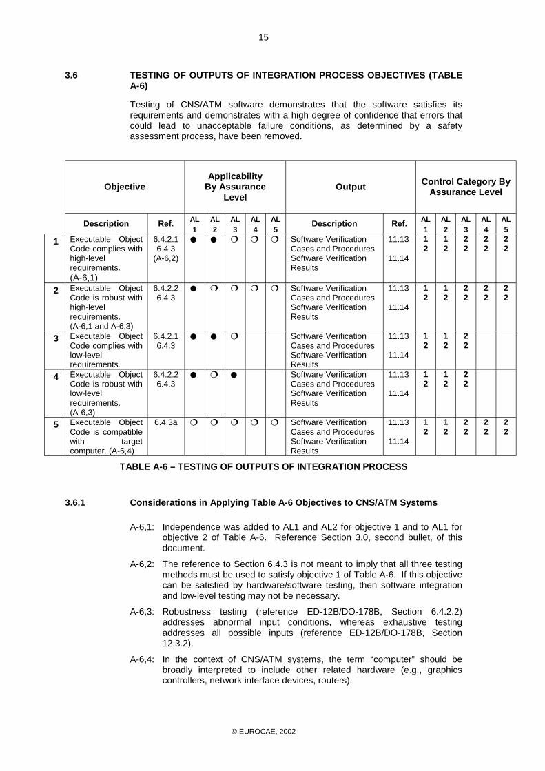
3.6 TESTING OF OUTPUTS OF INTEGRATION PROCESS OBJECTIVES (TABLE A-6)
Testing of CNS/ATM software demonstrates that the software satisfies its requirements and demonstrates with a high degree of confidence that errors that could lead to unacceptable failure conditions, as determined by a safety assessment process, have been removed.
Objective Applicability
By Assurance Level
Output Control Category By Assurance Level
Description Ref. AL 1
AL 2
AL 3
AL 4
AL 5
Description Ref. AL 1
AL 2
AL 3
AL 4
AL 5
1 Executable Object Code complies with high-level requirements. (A-6,1)
6.4.2.1 6.4.3
(A-6,2)
# # $ $ $ Software Verification Cases and Procedures Software Verification Results
11.13 11.14
1 2
1 2
2 2
2 2
2 2
2 Executable Object Code is robust with high-level requirements. (A-6,1 and A-6,3)
6.4.2.2 6.4.3
# $ $ $ $ Software Verification Cases and Procedures Software Verification Results
11.13 11.14
1 2
1 2
2 2
2 2
2 2
3 Executable Object Code complies with low-level requirements.
6.4.2.1 6.4.3
# # $ Software Verification Cases and Procedures Software Verification Results
11.13 11.14
1 2
1 2
2 2
4 Executable Object Code is robust with low-level requirements. (A-6,3)
6.4.2.2 6.4.3
# $ # Software Verification Cases and Procedures Software Verification Results
11.13 11.14
1 2
1 2
2 2
5 Executable Object Code is compatible with target computer. (A-6,4)
6.4.3a $ $ $ $ $ Software Verification Cases and Procedures Software Verification Results
11.13 11.14
1 2
1 2
2 2
2 2
2 2
TABLE A-6 – TESTING OF OUTPUTS OF INTEGRATION PROCESS
3.6.1 Considerations in Applying Table A-6 Objectives to CNS/ATM Systems
A-6,1: Independence was added to AL1 and AL2 for objective 1 and to AL1 for objective 2 of Table A-6. Reference Section 3.0, second bullet, of this document.
A-6,2: The reference to Section 6.4.3 is not meant to imply that all three testing methods must be used to satisfy objective 1 of Table A-6. If this objective can be satisfied by hardware/software testing, then software integration and low-level testing may not be necessary.
A-6,3: Robustness testing (reference ED-12B/DO-178B, Section 6.4.2.2) addresses abnormal input conditions, whereas exhaustive testing addresses all possible inputs (reference ED-12B/DO-178B, Section 12.3.2).
A-6,4: In the context of CNS/ATM systems, the term “computer” should be broadly interpreted to include other related hardware (e.g., graphics controllers, network interface devices, routers).

© EUROCAE, 2002
16
3.7 VERIFICATION OF VERIFICATION PROCESS RESULTS OBJECTIVES (TABLE A-7)
The verification of verification process results ensure that tests were developed accurately and completely and that the appropriate level of coverage for both requirements and software structure was achieved.
Objective Applicability
By Assurance Level
Output Control Category By Assurance Level
Description Ref. AL 1
AL 2
AL 3
AL 4
AL 5
Description Ref. AL 1
AL 2
AL 3
AL 4
AL 5
1 Test procedures are correct.
6.3.6b # $ $ $ Software Verification Results (A-7,1)
11.14 2 2 2 2
2 Test results are correct and discrepancies explained.
6.3.6c # $ $ $ Software Verification Results
11.14 2 2 2 2
3 Test coverage of high-level requirements is achieved. (A-7,2)
6.4.4.1 (A-7,3)
# $ $ $ $ Software Verification Results
11.14 2 2 2 2 2
4 Test coverage of low-level requirements is achieved. (A-7,2)
6.4.4.1 # $ $ Software Verification Results
11.14 2 2 2
5 Test coverage of software structure (modified condition/decision) is achieved.
6.4.4.2a 6.4.4.2b (A-7,4)
# Software Verification Results
11.14 2
6 Test coverage of software structure (decision coverage) is achieved.
6.4.4.2a 6.4.4.2b
# # Software Verification Results
11.14 2 2
7 Test coverage of software structure (statement coverage) is achieved.
6.4.4.2a 6.4.4.2b
# # $ Software Verification Results
11.14 2 2 2
8 Test coverage of software structure (data coupling and control coupling) is achieved.
6.4.4.2c # # $ $ Software Verification Results
11.14 2 2 2 2
TABLE A-7 – VERIFICATION OF VERIFICATION PROCESS RESULTS
© EUROCAE, 2002
17
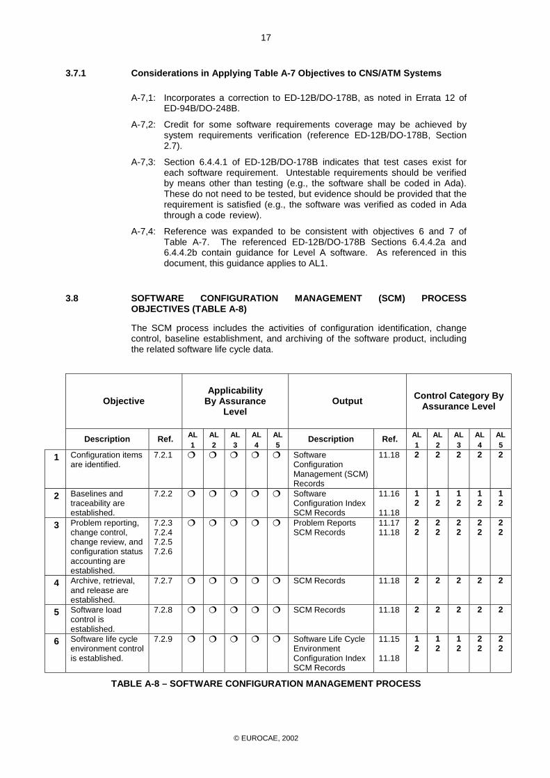
3.7.1 Considerations in Applying Table A-7 Objectives to CNS/ATM Systems
A-7,1: Incorporates a correction to ED-12B/DO-178B, as noted in Errata 12 of ED-94B/DO-248B.
A-7,2: Credit for some software requirements coverage may be achieved by system requirements verification (reference ED-12B/DO-178B, Section 2.7).
A-7,3: Section 6.4.4.1 of ED-12B/DO-178B indicates that test cases exist for each software requirement. Untestable requirements should be verified by means other than testing (e.g., the software shall be coded in Ada). These do not need to be tested, but evidence should be provided that the requirement is satisfied (e.g., the software was verified as coded in Ada through a code review).
A-7,4: Reference was expanded to be consistent with objectives 6 and 7 of Table A-7. The referenced ED-12B/DO-178B Sections 6.4.4.2a and 6.4.4.2b contain guidance for Level A software. As referenced in this document, this guidance applies to AL1.
3.8 SOFTWARE CONFIGURATION MANAGEMENT (SCM) PROCESS OBJECTIVES (TABLE A-8)
The SCM process includes the activities of configuration identification, change control, baseline establishment, and archiving of the software product, including the related software life cycle data.
Objective Applicability
By Assurance Level
Output Control Category By Assurance Level
Description Ref. AL 1
AL 2
AL 3
AL 4
AL 5
Description Ref. AL 1
AL 2
AL 3
AL 4
AL 5
1 Configuration items are identified.
7.2.1 $ $ $ $ $ Software Configuration Management (SCM) Records
11.18 2 2 2 2 2
2 Baselines and traceability are established.
7.2.2 $ $ $ $ $ Software Configuration Index SCM Records
11.16 11.18
1 2
1 2
1 2
1 2
1 2
3 Problem reporting, change control, change review, and configuration status accounting are established.
7.2.3 7.2.4 7.2.5 7.2.6
$ $ $ $ $ Problem Reports SCM Records
11.17 11.18
2 2
2 2
2 2
2 2
2 2
4 Archive, retrieval, and release are established.
7.2.7 $ $ $ $ $ SCM Records 11.18 2 2 2 2 2
5 Software load control is established.
7.2.8 $ $ $ $ $ SCM Records 11.18 2 2 2 2 2
6 Software life cycle environment control is established.
7.2.9 $ $ $ $ $ Software Life Cycle Environment Configuration Index SCM Records
11.15 11.18
1 2
1 2
1 2
2 2
2 2
TABLE A-8 – SOFTWARE CONFIGURATION MANAGEMENT PROCESS

© EUROCAE, 2002
18
3.8.1 Considerations in Applying Table A-8 Objectives to CNS/ATM Systems
None Identified.
3.9 SOFTWARE QUALITY ASSURANCE (SQA) PROCESS OBJECTIVES (TABLE A-9)
The SQA process provides assurance that the software life cycle processes produce software that conforms to its requirements by assuring that these processes are performed in compliance with the approved software plans and standards.
Objective Applicability
By Assurance Level
Output Control Category By Assurance Level
Description Ref. AL 1
AL 2
AL 3
AL 4
AL 5
Description Ref. AL 1
AL 2
AL 3
AL 4
AL 5
1 Assurance is obtained that software development and integral processes comply with approved software plans and standards.
8.1a (A-9,1)
# # # # # Software Quality Assurance (SQA) Records
11.19 2 2 2 2 2
2 Assurance is obtained that transition criteria for the software life cycle processes are satisfied. (A-9,2)
8.1b # # # # # SQA Records 11.19 2 2 2 2
3 Software conformity review is conducted. (A-9,3)
8.1c 8.3
# # # # # SQA Records 11.19 2 2 2 2 2
TABLE A-9 – SOFTWARE QUALITY ASSURANCE PROCESS
3.9.1 Considerations in Applying Table A-9 Objectives to CNS/ATM Systems
A-9,1: Objective 1 of Table A-9 references Section 8.1a of ED-12B/DO-178B; that section uses the words “approved plans.” Note that the use of the word approval in this paragraph is not necessarily the same as approval by an external “Approval Authority.”
A-9,2: Independence is applicable for AL3 and AL4 of objective 2 of Table A-9 to ensure that the transition criteria defined for AL3 and AL4 in Table A-1 is applied during the development.
A-9,3: Objective 3 of Table A-9 assures completion of the development and verification processes before submittal for approval.

© EUROCAE, 2002
19
3.10 SOFTWARE APPROVAL PROCESS OBJECTIVES (TABLE A-10)
The approval process establishes communication and understanding between the supplier and the Approval Authority throughout the software life cycle to assist the approval process.
Objective Applicability
By Assurance Level
Output Control Category By Assurance Level
Description Ref. AL 1
AL 2
AL 3
AL 4
AL 5
Description Ref. AL 1
AL 2
AL 3
AL 4
AL 5
1 Communication and understanding between the supplier and the Approval Authority is established.
9.0
$ $ $ $ $ Plan for Software Aspects of Approval (A-10,1)
5.1* 1 1 1 1 1
2 The means of compliance is proposed and agreement with the Plan for Software Aspects of Approval is obtained.
9.1 $ $ $ $ $ Plan for Software Aspects of Approval (A-10,1)
5.1* 1 1 1 1 1
3 Compliance substantiation is provided.
9.2 $ $ $ $ $ Software Accomplishment Summary Software Configuration Index
11.20 11.16
1 1
1 1
1 1
1 1
1 1
TABLE A-10 – SOFTWARE APPROVAL PROCESS
(* indicates reference to this document)
3.10.1 Considerations in Applying Table A-10 Objectives to CNS/ATM Systems
A-10,1: The purpose of the PSAA is to document the plans and procedures associated with the approval process for software to be used in CNS/ATM systems. Reference Section 5.1 of this document for further details on the PSAA.
© EUROCAE, 2002
20
CHAPTER 4
ADDITIONAL CONSIDERATIONS FOR CNS/ATM SOFTWARE
This section provides additional guidance for the CNS/ATM community in areas not expressly addressed in ED-12B/DO-178B or for which additional guidance or clarification is deemed necessary due to the specific attributes of software developed or deployed in the CNS/ATM environment. The two specific areas addressed in this section are: (1) Commercial Off-The-Shelf (COTS) software and (2) Adaptation data.
NOTE: In cases where COTS software requires adaptation data, both the COTS guidance and adaptation data sections apply.
4.1 COMMERCIAL OFF-THE-SHELF (COTS) SOFTWARE
COTS software encompasses a wide range of software, including purchased software, Non-Developmental Items (NDI), and software previously developed without consideration of DO-278/ED-109. The term “Previously Developed Software” is also used for such software. This software may or may not have been approved through other “approval processes.” Partial data or no data may be available as evidence of compliance with objectives provided in Section 3 of this document. For the rest of this section, all such software is referred to as COTS for the sake of brevity. This terminology was selected because of the usual use of the term “COTS” within the CNS/ATM community.
4.1.1 Introduction
Development processes used by COTS suppliers and procurement processes applied by acquirers may not be equivalent to processes used in the aviation industry, and may not be fully consistent with the guidance in Section 3 of this document. The use of COTS may mean that alternate methods are used to gain assurance that the appropriate objectives are satisfied. These methods include, but are not limited to, product service experience, prior assurance, process recognition, reverse engineering, restriction of functionality, formal methods, and audits and inspections. Software conformity review may need to be tailored with respect to the approach used for COTS approval. Assurance data may also be combined from more than one method to satisfy the objectives in Section 3.
In cases where sufficient data is not available to satisfy the objectives in Section 3 for a particular assurance level, this section may be used as guidance with agreement from the appropriate Approval Authority, as part of the Plan for Software Aspects of Approval process.
4.1.2 Scope of COTS Section
This section applies only to COTS used for CNS/ATM applications and is not intended to alter or substitute any of the objectives stated in Section 3 applied to CNS/ATM software, unless justified by a safety assessment process and accepted by the appropriate Approval Authority.

© EUROCAE, 2002
21
Examples of software often implemented by COTS are operating systems, real-time kernels, graphical user interfaces, communication and telecommunication protocols, language run-time libraries, mathematical and low-level bit routines, and string manipulation routines. COTS software can be purchased apart from or in conjunction with COTS hardware, such as workstations, mainframes, communication and network equipment, or hardware items (e.g., memory, storage, I/O devices). There also may be some instances where the use of COTS software is impractical to avoid, e.g., library code associated with certain compilers.
COTS deliverables vary by the contract with the COTS supplier. They may extend from license rights, executable code, user documentation, and training to the full set of COTS life cycle data, including the source code resulting from the COTS development. COTS information disclosure relates to cost, protection of intellectual property, and legal questions (e.g., ownership of the software, patents, liability, and documentation responsibility). These aspects are beyond the scope of this guidance material, which addresses only those aspects that are specific to software assurance.
4.1.3 System Aspects Relating to COTS in CNS/ATM Systems
COTS software may need to be integrated into high integrity CNS/ATM systems or equipment; however, the higher the failure condition classification of the CNS/ATM function, the more demanding the assurance requirements are for the system and the software. Alternate methods may be used to augment design assurance data for COTS software components at a desired assurance level. When COTS are used in a CNS/ATM system, additional considerations such as planning, acquisition, and verification should be addressed.
Risk mitigation techniques may be used to reduce the CNS/ATM system’s reliance on the COTS. The goal of these mitigation techniques is to accommodate the assigned failure condition classification by reducing the effect of anomalous behaviour of COTS on the CNS/ATM system function. Risk mitigation techniques may be achieved through a combination of people, procedure, equipment, or architecture. For example, architectural means may involve partitioning, redundancy, safety monitoring, COTS safe subsets by the use of encapsulation or wrappers, and data integrity checking.
Reference Section 2 of this document for related topics.
4.1.4 COTS Planning Process
The purpose of the COTS planning process is to coordinate life cycle processes specific to COTS and define the methods and tools necessary for the incorporation of COTS in CNS/ATM systems. The COTS planning process is a sub-activity of the supplier’s software planning process. The verification of the COTS planning process is to assure that all issues regarding the use of COTS have been addressed. The supplier’s software planning process should accommodate COTS software if its use is anticipated. The COTS planning process includes planning for software aspects of COTS, including acquisition, verification, configuration management, and software quality assurance.
As part of the approval process, early submittal of the results of the COTS assessment and selection processes to the appropriate Approval Authority is recommended.

© EUROCAE, 2002
22
4.1.4.1 COTS Planning Process Objectives
The objectives of the COTS planning process are:
a. Activities for acquisition and integral processes, including additional considerations, integration, and maintenance, are defined.
b. Transition criteria for these processes and transition criteria with respect to CNS/ATM software life cycle processes are defined.
c. Plans for COTS processes, including COTS transition criteria, are consistent with the supplier’s software plans.
4.1.4.2 COTS Planning Process Activities
The activities associated with the COTS planning process are:
a. COTS planning activities should evaluate the level of applicability of the COTS product to CNS/ATM software requirements. The following considerations should be included in the evaluation to determine the level of effort involved in the use of COTS:
(1) Product availability.
(2) Requirements (mapping of CNS/ATM requirements to COTS capabilities; reference Section 4.1.5 of this document).
(3) Availability and applicability of life cycle data.
(4) Level of integration and extent of additional efforts, such as, glue code, architecture mitigation techniques, etc., to allow incorporation of the COTS into the CNS/ATM system.
(5) Availability and applicability of product service history or service experience.
(6) COTS supplier qualifications, such as, the use of standards, service history and length of service, technical support, etc.
(7) Configuration control, including visibility of COTS supplier’s product version control.
(8) Modification considerations. Modified COTS has additional considerations of warranty, authority to modify, continued technical support, etc., unless such modifications are allowed by the COTS supplier. The modifications themselves should be considered a new development. Change impact analysis should be performed to determine the extent of the necessary re-verification.
(9) Maintenance issues (e.g., patches, retirement, obsolescence, and change impact analysis).
(10) Evidence of SQA activities.
(11) Verifiability of the COTS software (includes limitations, need for special test facilities, etc.).
(12) Level of compliance with ED-109/DO-278 objectives.
(13) Availability and applicability of information on COTS in-service problems and resolution of those problems.

© EUROCAE, 2002
23
b. Relationships between the COTS planning process, the COTS acquisition process, and the COTS integral processes should be defined. Additionally, relationships between COTS processes and appropriate CNS/ATM life cycle processes should be defined. Every input to a process need not be complete before that process can be initiated, if the transition criteria established for the process are satisfied.
c. Reviews should be conducted to ensure:
(1) The COTS planning process and the CNS/ATM planning process are consistent.
(2) COTS transition criteria are compatible with the CNS/ATM transition criteria.
(3) Transition criteria are verified to assure that the outputs of each process are sufficient to begin the next process.
NOTE: COTS usage may necessitate considerations of glue code, architectural mitigation techniques, derived requirements, and COTS-specific integration. Any supplemental software due to COTS integration in CNS/ATM systems should be considered CNS/ATM developmental software for which all of the objectives in Section 3 of this document apply.
4.1.5 COTS Acquisition Process
The focus of this section is on the assurance aspects of acquiring COTS. There are additional acquisition considerations not described in this document. The COTS acquisition process is comprised of requirements definition, assessment, and selection.
a. Requirements Definition: The CNS/ATM software requirements definition process identifies software requirements that COTS may satisfy. COTS may contain more capabilities than the requirements needed by the CNS/ATM system. A definition of these capabilities may be available from the COTS supplier or derived from the COTS user’s manuals, technical materials, product data, etc. In the model depicted in Figure 4-1, the CNS/ATM software requirements satisfied by COTS are the intersection of COTS capabilities and CNS/ATM requirements.
Due to the use of COTS, there may be derived requirements (e.g., platform dependent requirements, interrupt handling, interface handling, resource requirements, usage constraints, error handling, partitioning) that should be added to the CNS/ATM software requirements.
All CNS/ATM requirements satisfied by the COTS software and the resulting derived requirements should be provided to the safety assessment process.

© EUROCAE, 2002
24
CNS/ATMSoftware
Requirements
COTSCapabilities
CNS/ATM SoftwareRequirements satisfied by
COTS
FIGURE 4-1 – REQUIREMENTS INTERSECTION
b. Assessment: Candidate COTS products should be assessed for their ability to implement the CNS/ATM requirements, for the effect of their respective derived requirements, and for their support of the needed assurance level. During the COTS assessment process, more than one COTS candidate product may be examined to determine the extent of intersection of COTS capabilities with the CNS/ATM requirements as depicted in Figure 4-1. Availability and relevance of COTS life cycle data to support the appropriate assurance level should also be assessed. Additionally, the impact of any unneeded COTS capabilities should be assessed.
c. Selection: The selection is an iterative process based on results from the assessment process and comparison of COTS suppliers (e.g., COTS supplier’s capabilities to support CNS/ATM, the ability of the COTS supplier to support COTS software version control and maintenance over the expected lifetime of the CNS/ATM system, COTS supplier’s commitment to keep the CNS/ATM supplier informed of detected errors, COTS supplier’s willingness to address the issue of escrow). Analyses may be conducted to compare advantages of using COTS versus developing the software.
4.1.5.1 COTS Acquisition Process Objectives
The objectives of the COTS acquisition process are:
a. The degree to which of the CNS/ATM software requirements are satisfied by the COTS capabilities is determined.
b. The adequacy of life cycle data available for assurance purposes is determined.

© EUROCAE, 2002
25
c. The derived requirements are identified. Derived requirements consist of:
(1) Requirements imposed on the CNS/ATM system due to the usage of COTS.
(2) Requirements to prevent the unneeded capabilities of the COTS from adversely affecting the CNS/ATM system.
d. The compatibility of COTS with target hardware and other CNS/ATM software is assured.
4.1.5.2 COTS Acquisition Process Activities
The activities of the COTS acquisition process are:
a. The COTS capabilities should be examined, and an analysis should be conducted against the CNS/ATM requirements. The purpose of this analysis is to determine the CNS/ATM requirements satisfied by COTS and to aid in the comparison of candidate COTS products.
b. Available COTS software life cycle data should be assessed. A gap analysis should be performed against the objectives of Section 3 of this document for the proposed software assurance level. This analysis aids in comparison of candidate COTS products. This analysis is used to identify the objectives that are partially or fully satisfied, and those that need to be addressed through alternate methods.
c. Analysis should be conducted to identify derived requirements. This analysis should include all COTS software capabilities, both necessary and unnecessary. Derived requirements may be classified as follows.
(1) Requirements to prevent adverse effects of any unneeded functions of any COTS software. This may result in requirements for isolation, partitioning, wrapper code, coding directives, customization, etc.
(2) Requirements that the selected COTS may impose on the CNS/ATM system including those for preventing adverse effects of needed COTS functions (e.g. input formatting, call order, initialization, data conversion, resources, range checking). This may result in requirements for interface code, coding directives, architecture considerations, resource sizing, glue-code, etc.
d. All CNS/ATM requirements satisfied by COTS software, the resulting derived requirements, and any pertinent COTS supplier-provided data should be provided to the safety assessment process.
e. The selected COTS should be shown to be compatible with the target computer(s) and interfacing systems.
4.1.6 COTS Verification Process
The COTS verification process is an extension of the verification process discussed in Section 3 of this document. In particular, the COTS acquisition process frequently identifies verification objectives that cannot be satisfied using traditional means. For those verification objectives where compliance cannot be demonstrated by the available COTS data (e.g., design or requirements), additional activities, including alternate methods such as reverse engineering, may be used after acceptance by the Approval Authority.
The use of alternate methods should satisfy both of the following conditions:
a. The safety assessment process supports the justification.
b. Acceptance is granted by the appropriate Approval Authority.

© EUROCAE, 2002
26
Activities used for specific alternate methods or for combination of alternate methods are considered on a case-by-case basis. An example of activities associated with the usage of service experience for assurance credit is provided below in Section 4.1.6.3.
4.1.6.1 COTS Verification Process Objectives
There are no additional verification objectives imposed upon the CNS/ATM system because of use of COTS.
4.1.6.2 COTS Verification Process Activities
Typical verification activities for COTS software achieved according to Section 3 of this document include:
a. Software reviews and analyses of CNS/ATM software requirements satisfied by COTS,
b. Requirements-Based Testing (RBT) of CNS/ATM software requirements satisfied by COTS,
c. Verification of development of any supplemental software due to COTS (e.g., glue code, partitioning, wrappers), and
d. Verification of integration of COTS into the CNS/ATM system.
4.1.6.3 Use of Service Experience for Assurance Credit of COTS Software
Use of service experience data for assurance credit is predicated upon two factors: sufficiency and relevance. Sufficient service experience data may be available through the typical practice of running new CNS/ATM systems in parallel with operational systems in the operational environment, long duration of simulation of new CNS/ATM systems, and multiple shadow operations executing in parallel at many locations. Relevant service experience data may be available for CNS/ATM systems from reuse of COTS software from in-service CNS/ATM Systems, or CNS/ATM system verification and pre-operational activities, such as training. For COTS software with no precedence in CNS/ATM applications, many processes may be used to collect service experience; examples include the validation process, the operator training process, the system qualification testing, the system operational evaluation, and field demonstrations.
The following applies for accumulation of service experience:
a. The use, conditions of use, and results of COTS service experience should be defined, assessed by the safety assessment process, and submitted to the appropriate Approval Authority.
b. The COTS operating environment during service experience time should be assessed to show relevance to the intended use in CNS/ATM. If the COTS operating environment of the existing and intended applications differ, additional verification should be performed to ensure that the COTS application and the CNS/ATM applications will operate as intended in the target environment. It should be assured that COTS capabilities to be used are exercised in all operational modes. Analysis should also be performed to assure that relevant permutations of input data are executed.
c. Any changes made to COTS during service experience time should be analyzed. An analysis should be conducted to determine whether the changes made to COTS alter the applicability of the service experience data for the period preceding the changes.

© EUROCAE, 2002
27
d. All in-service problems should be evaluated for their potential adverse effect on CNS/ATM system operation. Any problem during service experience time, where COTS implication is established and whose resulting effect on CNS/ATM operations is not consistent with the safety assessment, should be recorded. Any such problem should be considered a failure. A failure invalidates the use of related service experience data for the period of service experience time preceding the correction of that problem.
e. COTS capabilities which are not necessary to meet CNS/ATM requirements should be shown to provide no adverse effect on CNS/ATM operations.
f. Service experience time should be the accumulated in-service hours. The number of copies in service should be taken into account to calculate service experience time, provided each copy and associated operating environment are shown to be relevant, and that a single copy accounts for a certain pre-negotiated percentage of the total.
NOTE: Available COTS data may not be able to demonstrate satisfaction of all of the verification objectives described in Section 3 of this document. For example, high-level requirements testing for both robustness and normal operation may be demonstrated for COTS but the same tests for low-level requirements may not be accomplished. The use of service experience may be proposed to demonstrate satisfaction of these verification objectives for COTS. The amount of service experience to be used is selected based on engineering judgement and experience with the operation of CNS/ATM systems. The results of software reliability models cannot be used to justify service experience time. A possible approach for different assurance levels is provided below:
(1) Cannot be applied for AL1.
(2) A duration of service experience with no failure for AL2 with the timeframe negotiated with the appropriate Approval Authority.
(3) A minimum of one year (8,760 hours) of service experience with no failure for AL3.
(4) A minimum of six months (4,380 hours) of service experience with no failure for AL4.
(5) AL5 objectives are typically satisfied without a need for alternate methods.
4.1.7 COTS Configuration Management Process
This section describes the configuration management process for a system using COTS. The configuration management system of the COTS supplier is not under the control of CNS/ATM configuration management system. The CNS/ATM configuration management system should include control of the COTS versions.

© EUROCAE, 2002
28
4.1.7.1 COTS Configuration Management Process Objectives
The objectives of the COTS configuration management process are:
a. The COTS specific configuration and data items (for example, software, documentation, adaptation data) are uniquely identified in the CNS/ATM software configuration management system.
b. The CNS/ATM problem reporting includes the management of problems found in COTS.
c. The CNS/ATM change control process ensures that the incorporation of COTS releases is controlled.
d. COTS-specific configuration and data items are included in the CNS/ATM archive, retrieval, and release.
4.1.7.2 COTS Configuration Management Process Activities
The activities associated with configuration management of COTS are:
a. An identification method should be established to ensure that the COTS configuration and data items are uniquely identified.
b. Note: The identification method may be based on identification from the COTS supplier and any additional data such as release or delivery date.
c. The CNS/ATM problem reporting should include management of problems found in COTS, and a bi-directional problem reporting mechanism with the COTS supplier should be established.
d. The CNS/ATM change control process for the incorporation of updated COTS versions should be established.
e. An impact analysis of changes to the COTS baseline should be performed prior to incorporation of new releases of COTS.
f. Note: The list of changes (problem fixes and new, changed, or deleted functions) implemented in each new release may be available from the COTS supplier.
g. The CNS/ATM archival, retrieval, and release should include COTS-specific configuration and data items.
h. Note: Consideration may be given to technology obsolescence issues for accessing archived data and escrow issues.
4.1.8 COTS Quality Assurance
The CNS/ATM quality assurance process should also assess the COTS processes and data outputs to obtain assurance that the objectives associated with COTS are satisfied.
NOTE: It is recommended that the COTS supplier quality assurance is coordinated with the CNS/ATM quality assurance process where feasible.

© EUROCAE, 2002
29
4.1.9 COTS Specific Objectives
The objectives contained within Section 4.1 (Tables 4-1 through 4-3) should be satisfied in addition to the objectives contained in Section 3 (Tables A-1 through A-10).
Objective Applicability
By Assurance Level
Output Control Category By Assurance Level
Description Ref. AL 1
AL 2
AL 3
AL 4
AL 5
Description Ref. AL 1
AL 2
AL 3
AL 4
AL 5
1 Acquisition and integral process plans are defined.
4.1.4.1a*
$ $ $ $ $ Software Development Plan
11.2
1 1 2 2 2
2 Transition criteria are defined.
4.1.4.1b*
$ $ $ $ $ Software Development Plan
11.2 1 1 2 2
3 COTS planning data are consistent with CNS/ATM software plans.
4.1.4.1c*
$ $ $ $ $ SQA Records 11.19
2 2 2 2
TABLE 4-1 – COTS PLANNING PROCESS OBJECTIVES
(* indicates reference to this document)
Objective Applicability
By Assurance Level
Output Control Category By Assurance Level
Description Ref. AL 1
AL 2
AL 3
AL 4
AL 5
Description Ref. AL 1
AL 2
AL 3
AL 4
AL 5
1 CNS/ATM requirements satisfied by the COTS software is determined.
4.1.5.1a*
# # $ $ $ Software Verification Results Design Description
11.14 11.10
2 2
2 2
2 2
2 2
2 2
2 Adequacy of life cycle data is determined.
4.1.5.1b*
$ $ $ $ $ Software Development Plan
11.2
1 1 2 2 2
3 Derived requirements are defined.
4.1.5.1c*
$ $ $ $ $ Software Requirements Data
11.9
1 1 1 1 1
4 Compatibility of COTS with target hardware and other CNS/ATM software is assured.
4.1.5.1d*
$ $ $ $ $ Software Verification Results
11.14
2 2 2 2 2
TABLE 4-2 – COTS ACQUISITION PROCESS OBJECTIVES
(* indicates reference to this document)

© EUROCAE, 2002
30
Objective Applicability
By Assurance Level
Output Control Category By Assurance Level
Description Ref. AL 1
AL 2
AL 3
AL 4
AL 5
Description Ref. AL 1
AL 2
AL 3
AL 4
AL 5
1 COTS configuration and data items are identified.
4.1.7.1a*
$ $ $ $ $ SCM Records 11.18
2 2 2 2 2
2 COTS problem reporting is established.
4.1.7.1b*
$ $ $ $ $ Problem Reports
11.17 2 2 2 2 2
3 Incorporation of COTS release is controlled.
4.1.7.1c*
$ $ $ $ $ SCM Records 11.18 2 2 2 2 2
4 COTS configuration and data items are archived.
4.1.7.1d*
$ $ $ $ $ SCM records 11.18 2 2 2 2 2
TABLE 4-3 – COTS CONFIGURATION MANAGEMENT PROCESS OBJECTIVES
(* indicates reference to this document)
4.2 ADAPTATION DATA PROCESS
Adaptation data is utilized to customize elements of the CNS/ATM system for its designated purpose at a specific location. These systems are often configured to accommodate site-specific characteristics. These site dependencies are developed into sets of adaptation data. Adaptation data includes:
! Data that configures the software for a given geographical site, and
! Data that configures a workstation to the preferences and/or functions of an operator.
Examples include, but are not limited to:
a. Geographical Data – latitude and longitude of a radar site.
b. Environmental Data – operator selectable data to provide their specific preferences.
c. Airspace Data – sector-specific data.
d. Procedures – operational customization to provide the desired operational role.
Adaptation data may take the form of changes to either database parameters or take the form of pre-programmed options. In some cases, adaptation data involves re-linking the code to include different libraries. Note that this should not be confused with recompilation in which a completely new version of the code is generated. In this latter case, the software represents a new and separate baseline and the guidance in Section 3.8 of this document applies. The guidance in ED-12B/DO-178B concerning user-modifiable software may be of some use in determining how to provide assurance for some adaptation data.
Adaptation data should be developed to the same assurance level of the code it modifies.

© EUROCAE, 2002
31
4.2.1 Adaptation Data Process Objectives
The purpose of the adaptation data process is to identify data that is to be adapted during the configuration or operation of a CNS/ATM system, to specify the mechanisms for accomplishing the adaptation, and to ensure that the requirements for such data are captured as part of the high-level requirements and/or associated low-level requirements. The objectives for the adaptation process are:
a. The data that may be adapted for a particular location is defined.
b. The mechanisms for generating and modifying adaptation data are defined for each location.
c. The objectives for verification, SQA, SCM, and approval processes are satisfied (reference Sections 3.3 through 3.10 of this document) for each location.
4.2.2 Adaptation Data Process Activities
Adaptation data activities include, but are not limited to: a. The life cycle process should address the application of adaptation data.
b. The high level requirements should identify the data that will be adapted.
c. The planning documents should address the mechanisms for generating and modifying adaptation data.

© EUROCAE, 2002
32
CHAPTER 5
CNS/ATM-SPECIFIC LIFE CYCLE DATA
This section discusses the content of new life cycle data items introduced for CNS/ATM systems by the guidance in document.
5.1 PLAN FOR SOFTWARE ASPECTS OF APPROVAL (PSAA)
The purpose of the PSAA is for the supplier to negotiate and obtain agreements with the Approval Authority.
In the PSAA, the supplier should propose a software life cycle that is commensurate with the rigor needed for the level of software being developed. This plan should cover topics addressed by Sections 11.1a through 11.1g of ED-12B/DO-178B; however, references to “certification” should be replaced with the word “approval.”
5.2 ADAPTATION DATA
Adaptation data defines specific CNS/ATM items that may be customized and which form a unique element of the high-level and the associated low-level requirements. The life cycle data items for adaptation data should include:
a. The description of data in the system that are adaptable and the inter-relationships or dependencies between the data. An example of inter-relationships or dependencies is the exact latitude and longitude for a radar station. The radar processor and the display system need to have the same value and should be updated together when changes occur.
b. The description of the mechanisms for generating and modifying adaptation data.
NOTE: If tools are employed in this process, tool qualification may be needed as specified in Section 12.2 of ED-12B/DO-178B.
5.3 COTS SOFTWARE LIFE CYCLE DATA
COTS-specific life cycle data items are:
a. Planning data as input to CNS/ATM planning data (reference Section 4.1.4 of this document).
b. Acquisition process data, including requirements definition, assessment, criteria, and rationale, for selection (reference Section 4.1.5 of this document).
c. Verification data, including any service experience data, that may be used for assurance credit (reference Section 4.1.6 of this document).

© EUROCAE, 2002
33
APPENDIX A
ACRONYMS AND GLOSSARY OF TERMS
ACRONYMS
AC Advisory Circular
AL Assurance Level
AMJ Advisory Material-Joint
ATC Air Traffic Control
ATM Air Traffic Management
ATS Air Traffic Services
CC1 Control Category 1
CC2 Control Category 2
CM Configuration Management
CNS Communication, Navigation, and Surveillance
COTS Commercial Off-The-Shelf
CPU Central Processing Unit
DP Discussion Paper
EUROCAE European Organisation for Civil Aviation Equipment
FAA Federal Aviation Administration
FAQ Frequently Asked Question
HW Hardware
I/O Input and Output
ISO International Organization for Standardization
JAA Joint Aviation Authorities
NDI Non-Developmental Item
PSAA Plan for Software Aspects of Approval
PSAC Plan for Software Aspects of Certification
QA Quality Assurance
RBT Requirements-Based Testing
RTCA RTCA, Inc.
SC Special Committee
SCM Software Configuration Management
SQA Software Quality Assurance
SW Software
TGL Temporary Guidance Leaflet
WG Working Group

© EUROCAE, 2002
34
GLOSSARY OF TERMS The following terms are either introduced in this document, or are used in a slightly different manner than in ED-12B/DO-178B.
Adaptation Data: Data used to customize elements of the Air Traffic System
for its designated purpose. Airborne: A qualifier used to denote software, equipment, or
systems onboard an aircraft. Approval: A means by which an authorized body gives formal
recognition that a product, process, service, or operation conforms to applicable requirements. NOTE 1: For example, approval is a generic term to
refer to certification, commissioning, qualification, initial operational capability, etc.
NOTE 2: The term “approval” is used slightly different from ED-12B/DO-178B to add clarification for CNS/ATM systems.
Approval Authority: The relevant body responsible for the approval in accordance with applicable approval requirements.
Architectural Mitigation:
Use of hardware and/or software architectural features, people, procedures, and/or equipment to eliminate, reduce, or control risk associated with an identified failure in a system.
Commercial Off-The-Shelf (COTS) Software:
Software under consideration for use in a CNS/ATM system that may have no or only partial evidence of compliance to ED-109/DO-278 Section 3 objectives. NOTE: The term “COTS software” is used slightly
different from ED-12B/DO-178B to add clarification for CNS/ATM systems.
Cutover: A process for switching from one operating version of software to another with limited or no interruption in service. This is also known as hot-swapping.
Escrow: A process by which data is placed under the control of an independent third party to ensure that the data is available to support approval activities throughout a system’s life cycle.
Gap Analysis: An engineering activity designed to identify the differences between a present state and the intended future state. In the context of this document, a gap analysis is conducted to identify what additional or alternate activities should be accomplished to comply with a specified set of objectives.
Glue Code: New code needed to integrate COTS code into a larger system, also known as “glueware” or “binding” code.
Hot-swapping: See Cutover In-service Hour: Use of software for one hour in a controlled environment
which is functionally equivalent to the target environment. Integrity: An attribute of a system or an item indicating that it can be
relied upon to work correctly on demand. Obsolescence: A condition in which hardware or software becomes out of
date and is no longer supportable, causing a need for replacement.
Non-Developmental Item (NDI):
An item not developed for the current contract. This is equivalent to previously developed software in ED-12B/DO-178B.

© EUROCAE, 2002
35
Pre-programmed Options:
User configurable functionality provided by the software. This is equivalent to option-selectable software in ED-12B/DO-178B.
Service Experience: Data obtained from the execution of software in a relevant, controlled environment over time. NOTE: The term “service experience” is used
slightly different from ED-12B/DO-178B to add clarification for CNS/ATM systems.
Software Assurance:
The planned and systematic actions necessary to provide confidence and evidence that a software product or process satisfies given requirements.
Software Development:
A set of activities that result in software products. Software development may include new development, modifications, reuse, reengineering, maintenance, or any other activities that result in software products.
Software Development Standard:
A standard that provides uniform requirements to be applied during the software development.
Software Integrity Assurance Standard:
A standard that provides criteria to evaluate and measure a software product and/or a process to provide assurance that the product and/or process satisfies given requirements and can be relied upon to work correctly in its intended environment. The criteria are a standard set of items dependent upon the software level and system failure condition classification, as determined by the system safety assessment process. The standard set of items is criteria to be applied to the software life cycle processes and data to demonstrate compliance to the documented process and correctness of the product. The software integrity assurance standard is the uniform measure of how the software was developed (the process) and a measure of the ability of the product to function as intended (the product).
Supplier: A person or organization seeking approval from the Approval Authority.
Wrapper Code: Software used to encapsulate some functionality of a system for the purpose of isolating it from the remaining functionality of the system.

© EUROCAE, 2002
36
APPENDIX B
BACKGROUND OF DOCUMENT ED-109/DO-278
B.1 SOFTWARE CONSIDERATIONS IN AIRBORNE SYSTEMS AND EQUIPMENT CERTIFICATION
ED-12B/DO-178B and its predecessors provide industry accepted guidance on how airworthiness requirements can be satisfied when using software in airborne systems and equipment.
ED-12B/DO-178B is formally recognized as a means of evaluating software for the purposes of complying with applicable regulations by the Federal Aviation Administration (FAA) in Advisory Circular (AC) 20-115B and by the Joint Aviation Authorities (JAA) in Temporary Guidance Leaflet (TGL) Number 4. Other Approval Authorities have similar means of recognizing ED-12B/DO-178B as a means of showing compliance to the regulations.
The International Organization for Standardization (ISO) recognized ED-12B/DO-178B as a de facto international standard in 1997.
ED-12B/DO-178B provides detailed guidelines for the production of software for airborne systems that perform intended functions with a level of confidence in safety and which comply with airworthiness requirements. This is achieved by:
! Defining objectives for the software life cycle processes;
! Identifying activities and design considerations which represent a means of satisfying these objectives; and,
! Providing a description of the evidence indicating the objectives have been satisfied.
ED-12B/DO-178B varies the rigor of the software development process according to the system failure condition classifications. The failure condition classes used are those adopted from FAA AC 25.1309-1A and/or the JAA Advisory Material – Joint (AMJ) 25.1309, as amended. The failure condition classifications are defined as catastrophic, hazardous/severe-major, major, minor, and no effect. ED-12B/DO-178B assumes that a system safety assessment process is applied to identify the appropriate failure condition classification and software level, from A to E, with Level A software having the highest integrity.
The main body of ED-12B/DO-178B identifies the objectives to be satisfied for Level A software. Annex A of the document identifies the objectives to be satisfied for each level. The general approach is that fewer objectives are needed to be satisfied as the software level is reduced.
B.3 THE NEED FOR ED-109/DO-278
Since publication, the aviation community has gained experience using ED-12B/DO-178B and raised a number of questions regarding the document’s content and application.

© EUROCAE, 2002
37
In order to address these questions, EUROCAE Working Group 52 (WG-52) was formed in February 1996 and, together with RTCA Special Committee 190 (SC-190), became a joint committee in September 1996. In 1999, this group issued ED-94/DO-248, First Annual Report for Clarification of ED-12B/DO-178B “Software Considerations in Airborne Systems and Equipment Certification.” A second annual report was issued in 2000 and a final report in 2001. The final report, ED-94B/DO-248B, contains all of the errata, Frequently Asked Questions (FAQ’s), and Discussion Papers (DP’s) approved by the committee.
Around the same time that SC-190 and WG-52 was established, another joint RTCA/EUROCAE group (SC-189/WG-53) was established. One of their tasks was to produce a safety assessment process that would identify the safety significance of software in CNS/ATM data communication systems. Assurance for software in the airborne systems was already addressed by ED-12B/DO-178B. However, guidance did not exist for software in CNS/ATM systems not located on the aircraft.
Some questions had also been provided to SC-190/WG-52 about how to address software in non-airborne systems that could affect the safety of aircraft directly or indirectly. As a result of these questions and the work being performed by SC-189/WG-53, SC-190/WG-52 established a team to:
“Develop guidance material based on ED-12B/DO-178B for Communication, Navigation and Surveillance (CNS) and Air Traffic Management (ATM) software shown by system safety assessment to affect the safety of aircraft occupants or airframe in its operational environment. Relevant software integrity assurance standards, and approval processes should be taken into account.”
After reviewing the applicability of ED-12B/DO-178B to CNS/ATM systems, it was decided to develop a new document containing guidance material. This became ED-109/DO-278. Some principles were established to guide the production of the guidance. These principles indicate the original intent of the guidance in this document:
! There should be no changes to the guidance to achieve certification of airborne systems.
! There should be consensus from the airborne and CNS/ATM community that the new guidance provides the same level of software integrity assurance for CNS/ATM non-airborne software of a given level as that obtained in airborne systems.
! There should be consensus from the non-airborne CNS/ATM community that the new guidance is practicable, feasible and relevant to non-airborne CNS/ATM software.
! Representatives from ATM service providers and equipment providers should be included on the working group.
! The regulators and certification authorities should find the guidance material being produced by the CNS/ATM team acceptable.
! Differences in regulatory and certification requirements for airborne and non-airborne systems should be considered during the preparation of the guidance material.
! There is no intent to change approval nor certification mechanisms as part of this activity.
! The new guidance should be reviewed against what is performed at present for CNS/ATM systems.
! The products produced by the CNS/ATM Team should be consistent with the products of SC-189/WG-53.

© EUROCAE, 2002
38
B.4 FEATURES OF ED-109/DO-278
The SC-190/WG-52 CNS/ATM team who developed the guidance included representatives from CNS/ATM service providers, equipment suppliers and regulators. This was intended to ensure that the guidance would be applicable to the industry that would have to apply it. The team reviewed guidance developed for the airborne segment of the civil aviation community (ED-12B/DO-178B). In some cases, the guidance was updated for application to CNS/ATM systems.
In preparing the guidance, consideration was given to:
1) Different regulatory environments for airborne and non-airborne systems.
The result was that all references to ‘certification’ were removed from the document.
2) Different characteristics of airborne and non-airborne systems including the environments in which they are used.
CNS/ATM systems operate continuously which demands high availability constraints.
These systems are also often large-scale, interconnected systems that make use of commercial services (e.g., telecommunications) as well as commercial software. In such systems, integration is the focus rather than development, and maintenance personnel usually support these systems at all times. This resulted in additional guidance being included for COTS software and adaptation data.
3) Lack of a common and accepted definition of failure conditions for non-airborne CNS/ATM systems
The result was that six software levels were established. These are referred to as Assurance Levels 1 to 6 in contrast to software levels A to E in ED-12B/DO-178B. The allocation of objectives to software levels was achieved by using the domain knowledge of the CNS/ATM team. It is assumed that anyone using the guidance material has their own processes to establish the appropriate software level.

© EUROCAE, 2002
39
APPENDIX C
COMMITTEE MEMBERSHIP
EXECUTIVE COMMITTEE MEMBERS
J. Krodel, United Technologies Research Center SC-190 Chair (since September 1999)
R. Seeman, Boeing SC-190 Chair (until September 1999)
J.-M. Nogué, EADS Airbus SA WG-52 Chair
M. DeWalt, Certification Services Inc. SC-190 Secretary
R. Hannan, Sigma Associates (Aerospace) WG-52 Secretary
L. Rierson, FAA FAA Representative and CAST Chair
CNS/ATM Leaders D. Hawken, National Air Traffic Services Ltd.
T. Ferrell, Ferrell and Associates Consulting
P. Wojnarowski, Boeing
J. Janelle, Honeywell
Editorial Team L. Rierson, FAA (Leader)
T. Ferrell, Ferrell and Associates Consulting
D. Hawken, National Air Traffic Services Ltd.
P. Mana, EUROCONTROL
R. Stroup, FAA
W. Struck, FAA
RTCA Representative R. Ruana
EUROCAE Representative F. Grimal

© EUROCAE, 2002
40
SC-190/WG-52 MEMBERS (* = Attended one or more meetings)
(# = CNS/ATM sub-group member) Name Organization K. Abell Hughes Information *J. Abraham University of Texas J. Ackland Boeing A. Ahmad DGAC India *N. Allen III Kollsman Inc. *M. Allocco TRW M. Almesåker Saab AB Sweden *P. Anders EADS *P. Andrews Rockwell Collins #*J. Angermayer MITRE Corporation *R. Ashpole BAE Systems - Airbus L. Atienza Innovative Solutions
International Inc. A. Bachmann IABG mbH J. Bailey Certification Services Inc. *S. Baranes DGAC/SPAe #*D. Barrow Thomson-CSF #*J. Bates CAA (SRG) ATS *T. Bauden FAA *B. Bauer Sextant Avionique *N. Bayram DASA/KID #*J. Beaufays EUROCONTROL P. Bennett Virtual Prototypes Inc. #*J. Besnard Raytheon Systems Co N. Bidikar Electronics Corporation of
India #*A. Blakeley National Air Traffic Services
Ltd. *M. Blankenberger
Rolls-Royce Allison
S. Bocvarov Innovative Solutions International Inc.
C. Bosco FAA *R. Bradley Coleman Research
Corporation I-L Bratteby-Ribbing
FMV - Swedish Defence Materiel Administration
*A. Bridge Bombardier Aerospace #*P. Brook Thales Avionics *J. Brookshire Lockheed Martin
Aeronautical #*D. Brown Rolls-Royce PLC *P. Brown UK Ministry of Defence #*J. Bryant RTCA R. Bull ERA Technology *J. Bureau Magellan Systems *R. Büse Diehl Avionik System R. Campaniello Aermacchi SpA W. Carl Certification Services Inc. #*Y. Carlier DGAC *G. Chang Air Economics Group Inc.
Name Organization *J. Chelini Verocel Inc. #*E. Chenevier STNA (DGAC) R. Cherry Consultant G. Clarke Honeywell #*J. Coleman Hamilton Sundstrand *N. Combes Fairchild Dornier #*R. Conrad Lockheed Martin #*P. Cook Sigma Associates
(Aerospace) D. Cooke Spirent Systems (Penny and
Giles) #*R. Cooley FAA C. Cosimini European Space Agency *S. Cullimore Smiths Industries
Aerospace #*M. Dabin Alcatel Space *P. Dagail CEAT/EL *M. Dangu Eurologiciel #*J. Daniels BAE Systems *B. Danner TRW P. Davies Logica Space Division *J-L. Delamaide CEAT *H. Delseny EADS #*N. Depoy TRW *C. Desquilbet CEAT/EL P. Devanbu University of California *P. Devlin Ultra Electronics Ltd #*M. DeWalt Certification Services Inc. *B. Dolman TRW Lucas Aerospace *N. Dorneau Sextant Avionique *C. Dorsey Digital Flight *V. Dovydaitis Foliage Software Systems
Inc. *P. Dunn Litton Aero Products M-H Durand Aerospatiale *L. Duthu Thompson *R. Eades BF Goodrich Aerospace #*A. Eaton CAA (SRG) ATS D. Egron AIRSYS ATM *J-M Eichner Ashtech *L. Elder ISI Inc *B. Elliott Harris ISD, TMS BAT R. Eno Spirent Systems (Penny and
Giles) H. Ernst Wehrtechnische Dienststelle
für Luftfahrzeuge F. Escaffre Bureau Veritas - Veridatas *C. Espinat DGAC *R. Evans Pratt & Whitney Canada *P. Eveleens National Aerospace
Laboratory

© EUROCAE, 2002
41
Name Organization #*T. Ferrell Ferrell and Associates
Consulting Inc. #*U. Ferrell Ferrell and Associates
Consulting Inc. *P. Fiduccia SAMA G. Finelli NASA *S. Fischer LITEF GmbH *D. Fisher ANPC *L. Fisk GE Aircraft Engines S. Fridrick GE Aircraft Engines *J. Fritts Allied Signal Aerospace *G. Frye FAA *F. Furlo II Coleman Research Corp. *R. Furstnau Rolls-Royce Allison *J-P Gagnaire SNECMA/ELECMA *T. Gallion Trimble Navigation *M. Gasiorowski Honeywell *P. Germanicus Intertechnique J. Gladstone Lockheed Martin Aero
Systems K. Gneiting IABG mbH P. Goodchild Stewart Hughes Limited D. Grabowski General Digital *F. Grimal EUROCAE #*M. Gulick Solers Inc B. Gumpel Fairchild Dornier GmbH *B. Gundlach BF Goodrich Avionic
Systems *R. Hall Harris A. Hamann FAA #*R. Hannan Sigma Associates
(Aerospace) J. Hansen Raytheon Aircraft Montek *D. Hatfield FAA K. Hathaway TRW Aeronautical Systems #*D. Hawken National Air Traffic Services
Limited #*D. Hawkes CAA *K. Hayhurst NASA *G. Haynes Rockwell Collins S. Haynes Avionics Specialties *P. Heller EADS *G. Henderson Ametek Aerospace #*C. Henry Thales ATM K. Hill Independent Consultant M. Hoff FAA *R. Hokans Honeywell #*C. M. Holloway
NASA Langley
P. Holmer Systems Resources Corp. *S. Hostert Rockwell Collins P. Hudson Raytheon Systems R. Humbertson MITRE Corporation #*G. Hunt EUROCAE K. Hunt BAE Systems - Airbus
Name Organization P. Hutchinson GEC Marconi *P. Huyck Rockwell-Collins S. Irving AMETEK Aerospace *R. Jackson Raytheon Systems Co. *J. Jacobs Avrotec *M. Jaffe Embry-Riddle Aeronautical
University *M. Jaglarz Transport Canada - Aviation #*J. Janelle Honeywell V. Joag Smiths Industries #*L. Johnson Boeing *C. Jones Bombardier Aerospace - de
Havilland Division *R. Jones FAA *F. Jordan CEAT #*M. Joseph MITRE Corporation *R. Kantkaz Oracle N. Kanuritch BAE Systems *O. Karoun SNECMA-ELECMA *J. Kerr Smiths Industries #*R. Key FAA *D. Kinney Boeing W. Kleine-Beek Bundesministerium für
Verkehr, Bau und Wohnungswesen
#*A. Kornecki Embry-Riddle Aeronautical University
*E. Kosowski Rockwell Collins #*T. Kraft FAA *M. Kress Boeing #*J. Krodel United Technologies
Research Center D. Kruth Oracle Corporation #*C. Kurkjian SITA *J-P Lachambre EADS *J. Lad Bombardier Aerospace #*G. Ladier EADS R. Lambalot Boeing *M. Lampton Rockwell Collins P. La Pietra AlliedSignal Engines &
Systems *P. Le Gac Bombardier Aerospace -
Canadair J. Lea-Jones ERA Technology V. Lebacqz NASA #A. Lee Advanced Navigation and
Positioning Corporation *H. Leung Asura Software Certification A. Lever Alcatel *M. Lillis Hamilton Sundstrand -UTC #*B. Lingberg FAA A. Link LBA, Germany M. Liu MITRE Corporation B. Lockwood Raytheon Systems *S. Lomax Magellan Systems Corp.

© EUROCAE, 2002
42
Name Organization P. Lorenzi Laben SpA *H. Lowe Smiths Industries
Aerospace #*J. Lynch Honeywell *A. Maclellan Honeywell S. Madaras Honeywell #*P. Mana Eurocontrol *J. Marcoux European Space Agency D. Masters Pratt and Whitney Aircraft #*W. Matheson Camber Corporation P. Matthews Pratt and Whitney Canada S. Matthews Avidyne Corp #*M. Maxfield Raytheon Aircraft #*I. McAnany Astrium *R. McCallister FAA #*F. McCormick Certification Services Inc. P. McFadden Logica *J. McGookey Smiths Industries G. McIntyre FAA *P. McKenna Smiths Industries A. McKinlay Booz, Allen, & Hamilton, Inc. *F. McLoughlin Seagull Technology #*J. Meer Microflight #*R. Mendez FAA *J. Meyers FAA #*C. Miles FAA *P. Moore UK Civil Aviation Authority S. Morgan UK Ministry of Defence U. Mortensen European Space Agency *F. Moyer Rockwell Collins *M. Muench Trimble Navigation C. Mugridge Defence Evaluation
Research Agency *W. Müller Diehl Avionik System #*A. Murthi Strategic Technology
Institute #*D. Nash Raytheon Company P. Naylor GKN Westland Helicopters #*W. Naylor BAE Systems *W. Neill Harris Corporation #*V. Nemeth MITRE Corporation C. Newton Defence Evaluation
Research Agency *D. Nguyen SDC Inc. *J. Nguyen SDC Inc *S. Nickerson GE Aircraft Engines *F. Nirschl AustroControl #*J-M Nogué EADS Airbus SA *J. Norris Eldec Corporation G. Noyes Windriver *S. Obeid I-Logix K. O'Neil Advanced Aviation
Technology *J. Orlando Lockheed Martin *G. Osborg Normarc AS
Name Organization *G. Ostrom Allied Signal CAS *S. Paasch Certification Services Inc. #*G. Paly SNECMA-ELECMA *B. B. Pedersen Kongsberg Aerospace *R. Pehrson Boeing #*J. Penny CAA SRG *B. Perret EUROCAE #*J. Petersen FAA #*B. Pflug Boeing *T. Phan FAA R. Pierce York Software Engineering #*G. Pilj Learjet *E. Piper Boeing M. Porzi Elmer SpA *F. Pothon Turbomeca *P. Prisaznuk AEEC ARINC *B. Pro AlliedSignal CAS P. Pulley Spirent Systems (Penny and
Giles) *J. Pumfrey CAA SRG ATS #*A. Pyster FAA *M. Ramsey AlliedSignal *R. Rao Transport Canada #*K. Rebai *T. Reeve AVTECH Co. *A. Reich Thales Avionics #*R. Renon Altron Technologies *T. Rhoads BF Goodrich Aerospace *M. Richardson Cessna Aircraft Co. #*L. Rierson FAA K. Rigby Independent Consultant #*D. Robinson FAA *L. Rogness Rockwell Collins *G. Romanski Verocel Inc. J. Ronback Raytheon Systems Canada T. Roth AlliedSignal CAS M. Roux Rockwell Collins France #*R. Ruana RTCA *B. Russell Chandler Evans *J-C Russo SNECMA-ELECMA R. Ryburn FAA C. Saderstrom Flight Dynamics *K. Sahlin AlliedSignal *P. Salmon Dassault Electronique *C. Salsen JAA/CEAT *L. Sanders Honeywell M. Sanders Dunlop Aviation *P. Saraceni FAA H. Schlickenmaier
NASA
D. Schmitz Penny and Giles Aerospace #*J-Y Schneider AIRSYS ATM W. Schoke Air Traffic Management
USAF

© EUROCAE, 2002
43
Name Organization #*C. Secher DGAC #*R. Seeman Boeing *R. Segredo Avionica Inc. *M. Severson Bell Helicopter Textron *J. Shah Parker-Hannifin ESD K. Shyne Boeing *L. Silva Smiths Industries #*L. Simon Rockwell Collins *R. Singh FAA *B. Smith The Soaring Society of
America and FAI *M. Smith Ametek Aerospace S. Smith FAA #*T. Smith ATSA D. Sniezek Lockheed Martin #*M. Sonnek Honeywell *R. Souter FAA *C. Spitzer Avionicon Inc. J. Srinivasan' MIT #*R. Stalford Astrium *C. Stallwitz Raytheon Aircraft *T. Starnes Cessna Aircraft Company W. Steinau German Air Navigation
Services *N. Stewart Airtel ATN *J. Stolzenthaler Hamilton Sundstrand *I. Strachan AEA Technology #*R. Stroup FAA #*W. Struck FAA *P. Stufflebeam Raytheon Aircraft Co. #*P. Swiderski Lockheed Martin #*C. Tabard Alcatel Space #*A. Tahir Aviso Inc. *G. Tamburro Registro Aeronautico
Italiano *N. Tank Ultra Electronics P. Taylor EDS *M. Temprement Sextant Avionique #*A. Theodore Universal Systems &
Technology – UNITECH #P. Thomas NATS *D. Thompson De Havilland Inc. *L. Thompson Honeywell #*M. Thorvaldsson
Swedish CAA
*A. Tochilin Ashtech Inc. C. Tofpi Honeywell #*T. Tougas Airsys ATM Inc. *O. Tourret STTE/AVI *L. Tripp Boeing I. Tutin Independent Consultant *J. van Baal RLD Department of Civil
Aviation S. Van Trees FAA *A. Vaudrey British Embassy –
Name Organization Washington, D.C.
D. Waite Aerospace Engineering & Research Inc.
*D. Wallace FAA *M. Warren Flight Dynamics #*R. Watkins FAA *D. Watrous RTCA *A. Wegiel Dassault Electronique *T. Weinstein Parker Hannifin Corporation B. Welldon Solution Pty Ltd. *B. Wendling Turbomeca M. Werenowski Airsys ATM *P. Whiston Stewart Hughes *E. Wiens Cessna Aircraft Co. *J. Williams FAA #*P. Wojnarowski
Boeing
*R. Wolf Consultant – Qual Quest #*K. Wolfley FAA A. Wright Rockwell Collins *J. Yang MITRE Corporation W. Young AlliedSignal Canada Inc. *B-J Ystanes Kongsberg Defence &
Aerospace *U. Zanker Liebherr Aerospace *D. Zellweger FAA

© EUROCAE, 2002
44
APPENDIX D
IMPROVEMENT SUGGESTION FORM
Name: __________________________________ Company Name: __________________________
Address: __________________________________________________________________________
City: __________________________ Postal code: _________Country: _______________________
Phone: _________________________________ Date: ____________________________________
Fax: ____________________________________ E-mail: __________________________________ DOCUMENT : DO-278/ED-109 Paragraph: __________ Page: __________ Line: ____________ % Editorial error (format, punctuation, spelling)
% Content error
% Enhancement or refinement Rationale (Describe the error or justification for enhancement):________________________________
__________________________________________________________________________________
__________________________________________________________________________________
__________________________________________________________________________________ Proposed change (attach marked-up text or proposed rewrite):________________________________
__________________________________________________________________________________
__________________________________________________________________________________ Please provide any general comments for improvement of this document: _______________________
__________________________________________________________________________________
__________________________________________________________________________________
__________________________________________________________________________________
Return completed form to:
RTCA, Inc. OR EUROCAE Attention: DO-278 Attention: ED-109 1828 L Street, NW, Suite 805 17 rue Hamelin Washington, DC 20036, USA 75783 Paris Cedex 16, France Fax: 33 1 4505 7230 E-mail: [email protected] Web site: www.eurocae.org Workspace, free access workspace, ED-109, new message, parcourir (if attached file), send (the text of message)