Embed Size (px)
Citation preview

KINGFISH MAINE SITE LOCATION OF DEVELOPMENT APPLICATION
SECTION 17: Wastewater Disposal
Kingfish Maine proposes to construct an enclosed recirculating aquaculture system (RAS) facility with multiple buildings, together with adjunct facilities and equipment on a property at 9 Mason Bay Road in Jonesport. This facility comprises facilities for staff and residential accommodations for staff. Appended to this section are designs for system 1 and system 2, including Subsurface Wastewater Disposal Design Applications (HHE 200 form) for the proposed subsurface wastewater disposal systems designed by Natalie Marceau, Licensed Site Evaluator #411 and by William T. Lane, PE 7577 for the engineered system. This submission includes the applications and supporting documentation.

KINGFISH MAINE SITE LOCATION OF DEVELOPMENT APPLICATION
APPENDIX 17A WASTEWATER DISPOSAL SYSTEM 2 DESIGN

33 SALMON FARM ROADFRANKLIN, ME 04634
(502) 387-8673 8 23
± 93.2
1,500
4 D1
12
21 ELJEN GSF MODULES
STORE (BUILDING #12)
385
44 33 16.167 34 38.2
(207) 236-4365
1 PUBLIC TOILET @ 325 GPD5 EMPLOYEES @ 12 GPD PER EMPLOYEE
2/10/21
Maine Dept. Health & Human Services
Division of Health Engineering, 10 SHS
(207) 287-2070 Fax: (207) 287-4172
City, Town,
or Plantation
>> CAUTION: LPI APPROVAL REQUIRED <<
SUBSURFACE WASTEWATER DISPOSAL SYSTEM APPLICATION
PROPERTY LOCATION
OWNER/APPLICANT INFORMATION
OWNER OR APPLICANT STATEMENT
I state and acknowledge that the information submitted is correct to the best of
my knowledge and understand that any falsification is reason for the Department
and/or Local Plumbing Inspector to deny a Permit.
__________ __________________________________ __________
Signature of Owner or Applicant Date
Street or Road
Subdivision, Lot #
Name (last, first, MI)
Owner
Applicant
Mailing Address
of
Owner/Applicant
Daytime Tel. #
THIS APPLICATION REQUIRES
1. No Rule Variance
2. First Time System Variance
3. Replacement System Variance
4. Minimum Lot Size Variance
5. Seasonal Conversion Permit
a. Local Plumbing Inspector Approval
b. State & Local Plumbing Inspector Approval
a. Local Plumbing Inspector Approval
b. State & Local Plumbing Inspector Approval
PERMIT INFORMATION
SITE EVALUATOR STATEMENT
DESIGN DETAILS (SYSTEM LAYOUT SHOWN ON PAGE 3)
DISPOSAL SYSTEM COMPONENTS
1. Complete Non-engineered System
2. Primitive System (graywater & alt. toilet)
3. Alternative Toilet, specify:____________
4. Non-engineered Treatment Tank (only)
5. Holding Tank, _______ gallons
6. Non-engineered Disposal Field (only)
7. Separated Laundry System
8. Complete Engineered System (2000 gpd or more)
9. Engineered Treatment Tank (only)
10. Engineered Disposal Field (only)
11. Pre-treatment, specify: _________
12. Miscellaneous Components
TYPE OF APPLICATION
1. First Time System
2. Replacement System
Type replaced: ______________
Year installed: ______________
3. Expanded System
a. <25% Expansion
b. ≥25% Expansion
4. Experimental System
5. Seasonal Conversion
SIZE OF PROPERTY
SQ. FT.
ACRES
SHORELAND ZONING
Yes No
DISPOSAL SYSTEM TO SERVE
1. Single Family Dwelling Unit, No. of Bedrooms: ____
2. Multiple Family Dwelling, No. of Units: _____
3. Other: __________________________
(specify)
Current Use Seasonal Year Round Undeveloped
EFFLUENT/EJECTOR PUMP
1. Not Required
2. May Be Required
3. Required
Specify only for engineered systems:
DOSE: __________ gallons
TREATMENT TANK
1. Concrete
a. Regular
b. Low Profile
2. Plastic
3. Other: ________________
CAPACITY: _________ GAL.
DISPOSAL FIELD TYPE & SIZE
1. Stone Bed 2. Stone Trench
3. Proprietary Device
a. cluster array c. Linear
b. regular load d. H-20 load
4. Other: _____________________
SIZE: ___________ sq. ft. lin. ft.
type: _____________________
GARBAGE DISPOSAL UNIT
1. No 2. Yes 3. Maybe
If Yes or Maybe, specify one below:
a. multi-compartment tank
b. ___ tanks in series
c. increase in tank capacity
d. Filter on Tank Outlet
SOIL DATA & DESIGN CLASS
PROFILE CONDITION
_______/___________
at Observation Hole #________
Depth _____"
of Most Limiting Soil Factor
DISPOSAL FIELD SIZING
1. Medium---2.6 sq. ft. / gpd
2. Medium---Large 3.3 sq. f.t / gpd
3. Large---4.1 sq. ft. / gpd
4. Extra Large---5.0 sq. ft. / gpd
DESIGN FLOW
_______________ gallons per day
BASED ON:
1. Table 4A (dwelling unit(s))
2. Table 4C (other facilities)
SHOW CALCULATIONS for other facilities
3. Section 4G (meter readings)
ATTACH WATER METER DATA
LATITUDE AND LONGITUDE
at center of disposal area
Lat. _______d _______m _______s
Lon. _______d _______m _______s
if g.p.s, state margin of error:_____________
I certify that on ____________ (date) I completed a site evaluation on this property and state that the data reported are accurate and
that the proposed system is in compliance with the State of Maine Subsurface Wastewater Disposal Rules (10-144A CMR 241).
__________ ____________________________ ____________________ _______________
Site Evaluator Signature SE # Date
______________________________________________ ________________ __________________________________
Site Evaluator Name Printed Telephone Number E-mail Address
HHE-200 Rev. 11/2013
Note: Changes to or deviations from the design should be confirmed with the Site Evaluator.
TYPE OF WATER SUPPLY
1. Drilled Well 2. Dug Well 3. Private
4. Public 5. Other
GARTLEY & DORSKYENGINEERING & SURVEYING
H:\Land Projects 3\19412 Kingfish\Drawings\Store septic\19412-HHE200 (for store).dwg
CAUTION: INSPECTION REQUIRED
I have inspected the installation authorized above and found it to be in compliance
with the Subsurface Wastewater Disposal Rules Application. _________________
(1st) date approved
__________________________________________ _______________________
Local Plumbing Inspector Signature (2nd) date approved
The Subsurface Wastewater Disposal System shall not be installed until a
Permit is issued by the Local Plumbing Inspector. The Permit shall
authorize the owner or installer to install the disposal system in accordance
with this application and the Maine Subsurface Wastewater Disposal Rules.
Town/City ____________________________ Permit # ___________
Date Permit Issued ___/___/___ Fee: $__________ Double Fee Charged [ ]
_____________________________________________ L.P.I. # ______________
Local Plumbing Inspector Signature
Municipal Tax Map # ____________ Lot # _________
Fee: $_________ state min fee $_________Locally adopted
fee copy [ ] Owner [ ] Town [ ] State
JONESPORT
DUN GARVIN ROAD
3/1/21
KINGFISH MAINE, INC.
Natalie Marceau ( )
411
PROJ. NO.: 2019-412
PROPOSED PUBLIC DRILLEDWELLS

OH
OH
OH
OH
A
B
C
D
REF. PT. A.NAIL 39" ABOVE
GRADE IN EMERAPOLE #121897
ERPNAIL 56" ABOVE GRADE
IN 9" BIRCH TREE
APPROXIMATELOCATION OF
PROPOSEDBUILDING #12
APPROXIMATE LOCATIONOF EXISTING BUILDINGS
TO BE REMOVED
PROPOSED 4" SDR 35 PIPE(18" DROP PER FOOT MINIMUM)
WITH MINIMUM ONECLEAN-OUT FOR EVERY 100FEET OF CONNECTING PIPE)
PROPOSED 4"SCH. 40 PIPE(14" DROP PER
FOOT MINIMUM)
±300' PUBLIC
WEL
L SET
BACK
PROPOSED 1500 GAL.CONCRETE SEPTIC TANK OFMONOLITHIC CONSTRUCTIONOR WATER TIGHT (SEESECTION 6(H)(8) OF THECODE. THE TANK SHALL BESET IN 4" LAYER OFCOMPACTED SAND ORGRAVEL (8' MIN. FROMBUILDING) WITH POLYLOKPL-250 (OR EQUIVALENT)FILTER AT OUTLET.
±300' PUBLIC WELL SETBACK
PROPOSED ACCESS DRIVE
EXISTINGGRAVEL
PROPOSED ACCESS DRIVE
(DUN GARVIN ROAD)
MASON BAY ROAD
(ROUTE 187) AWETLANDS
THE PROPOSED DISPOSALAREA CONSISTS OF 3 ROWSOF 7 ELJEN GEOTEXTILE SANDFILTER MODULES (TOTAL 21MODULES). ROWS SHALL BE1' APART AND INSTALLED PERMANUFACTURER'SRECOMMENDATIONS.
SUBSURFACE WASTEWATER DISPOSAL SYSTEM APPLICATION
Town, City, Plantation Street, Road, Subdivision
Department of Human Services
Division of Health Engineering
(207) 287-5672 Fax: (207) 287-3165
Owner's Name
SITE PLAN Scale 1" = __________ ft. or as shown SITE LOCATION PLAN
SOIL DESCRIPTION AND CLASSIFICATION (Location of Observation Holes Shown Above)
Page 2 of 4HHE-200 Rev. 8/01
Observation Hole _______ Test Pit Boring________ " Depth of Organic Horizon Above Mineral Soil
Observation Hole _______ Test Pit Boring________ " Depth of Organic Horizon Above Mineral Soil
Site Evaluator Signature SE # Date
Dep
th B
elow
Min
eral
Soi
l Sur
face
(inc
hes)
Soil Classification Slope Limiting [ ] Ground Water Factor [ ] Restrictive Layer_______ ________ ______ % [ ] Bedrock Profile Condition _____" [ ] Pit Depth
100
10
4 D ±412
Soil Classification Slope Limiting [ ] Ground Water Factor [ ] Restrictive Layer_______ ________ ______ % [ ] Bedrock Profile Condition _____" [ ] Pit Depth
Texture MottlingConsistency Color Texture MottlingConsistency Color
Dep
th B
elow
Min
eral
Soi
l Sur
face
(inc
hes)
BOTTOM OF TEST PIT
FRIABLE
DARKBROWN
NONESTRONGBROWN
LIGHT OLIVEBROWN
LOAMYSAND
COMMONMEDIUMDISTINCT
LIGHT OLIVEBROWN
JONESPORT DUN GARVIN ROAD KINGFISH MAINE, INC.
3/1/21411
SITE LOCATION
PROJ. NO.: 2019-412
LOAM

OH
OH
OH
OH
11'
28'
APPROX. TOE OFFILL EXTENSION
±4% SLOPE
-60"
A
-56"B
-66"C
-62"D
A
S
-
1
REF. PT. A.NAIL 39" ABOVE
GRADE IN EMERAPOLE #121897
ERPNAIL 56" ABOVE GRADEIN 9" BIRCH TREE
PROPOSED 4" SDR 35 PIPE(18" DROP PER FOOT MINIMUM)
WITH MINIMUM ONECLEAN-OUT FOR EVERY 100FEET OF CONNECTING PIPE)
PROPOSED 5 HOLE DISTRIBUTION BOXWITH EQUALIZERS SET IN 4" LAYER OF
COMPACTED SAND AND COVEREDWITH 2" OF STYROFOAM INSULATION.
A
±20'
±15'
±11'
±17'
APPROXIMATE LOCATIONOF EXISTING OVERHEAD
POWER LINE
WETLANDS
THE PROPOSED DISPOSALAREA CONSISTS OF 3 ROWSOF 7 ELJEN GEOTEXTILE SANDFILTER MODULES (TOTAL 21MODULES). ROWS SHALL BE1' APART AND INSTALLED PERMANUFACTURER'SRECOMMENDATIONS.
SUBSURFACE WASTEWATER DISPOSAL SYSTEM APPLICATION
Town, City, Plantation Street, Road, Subdivision
Department of Human Services
Division of Health Engineering
(207) 287-5672 Fax: (207) 287-3165
Owner's Name
SUBSURFACE WASTEWATER DISPOSAL PLANSCALE: 1" = ___________FT.
Page 3 of 4HHE-200 Rev. 8/01 Site Evaluator Signature SE # Date
FILL REQUIREMENTS
Depth of Fill (Upslope) __________
Depth of Fill (Downslope) __________
CONSTRUCTION ELEVATIONSFinished Grade Elevation _______Top of Distribution Pipe or Proprietary Device _______Bottom of Disposal Area _______
ELEVATION REFERENCE POINTLocation & Description:
Reference Elevation: ____________ SCALEHorizontal 1" = _____ ft.Vertical 1" = _____ ft.
DISPOSAL AREA CROSS SECTION
20
31"-35"
37"-41"
N/AN/A
DISTANCES:ELEVATION REFERENCE POINT (ERP): NAIL 56" ABOVE GRADE IN 9" BIRCH TREE
ERP TO A: 13'-1" ERP TO B: 32'-7" ERP TO C: 24'-1" ERP TO D: 38'-3"
0"
NAIL 56" ABOVE GRADE IN 9"BIRCH TREE
SEE SECTION-A
REFERENCE POINT A.:NAIL 39" ABOVE GRADE IN EMERA POLE #121897
REFERENCE POINT A TO A: 38'-5"REFERENCE POINT A TO B: 66'-2"REFERENCE POINT A TO C: 41'-6"REFERENCE POINT A TO D: 68'-1"
NOTE: ALL PROPERTY LINESARE APPROXIMATE.
(SEE ATTACHED SECTION)
JONESPORT DUN GARVIN ROAD KINGFISH MAINE, INC.
3/1/21
SEE SECTION-A
SEE SECTION-A
411
H:\Land Projects 3\19412 Kingfish\Drawings\Store septic\19412-HHE200 (for store).dwg PROJ. NO.: 2019-412

11'
3'SHOULDER
(@3% SLOPE)±9' ±16'
ERP = 0"
9" MIN.12" 3'
THE SYSTEM CONSISTS OF 3 ROWS OF 7 MODULES PER ROW, EACH ROW SEPARATED BY 1 FOOT.
EXISTING AVERAGE GRADE
LIMITING FACTOR(SEASONAL HIGH WATER TABLE)
BOTTOM OF 6" SPECIFIED SAND LAYER (SEE NOTE #6)
3'SHOULDER
ROW 1 ROW 2 ROW 3
2'-9" (TYP.)
4" (MIN) TRANSITIONAL HORIZON(A MIXTURE OF BACKFILL AND NATURAL SOIL)
4:1 SLOPE FILLEXTENSION.
BACKFILL(SEE NOTE #7)
4:1 SLOPE FILLEXTENSION.
BACKFILL(SEE NOTE #7)
SDR 35 PERFORATEDPIPE TYP.
GEOTEXTILE SAND FILTERMODULE BY ELJEN CORP.
ELEVATIONSELEV. REF. PT. (ERP) 0"
ROW 1 ROW 2 ROW 3FINISHED GRADE -25" -25" -25"TOP OF IN-DRAIN UNIT -37" -37" -37"BOTTOM OF IN-DRAIN UNIT -44" -44" -44"BOTTOM OF SAND -50" -50" -50"
SECTION-A
GNIYEVRUSENGINEERING& orskyDartleyG59B Union Street P.O. Box 1031 Camden, ME 04843-1031
Ph (207) 236-4365 Fax (207) 236-3055 Toll Free 1-888-282-4365
165 Main Street Suite 2F P.O. Box 1072 Damariscotta, Maine 04543Ph. (207) 790-5005
S-1
Page 4 of 4HHE-200 Rev. 8/01 Site Evaluator Signature SE # Date
Owner/Applicant:
Town:
Street:
Detail Scale:
3/1/211"= 5'
JONESPORT
DUN GARVIN ROAD
KINGFISH MAINE, INC.SUBSURFACE WASTEWATER DISPOSAL SYSTEM APPLICATION
GEOTEXTILE SAND FILTER NOTES:1. THIS SYSTEM COMPLIES WITH AND MUST BE INSTALLED IN ACCORDANCE WITH THE GEOTEXTILE SAND FILTER DESIGN
MANUAL (BY ELJEN CORPORATION), AND ALL MAINE SUBSURFACE RULES.2. INSTALLATION SHALL NOT TAKE PLACE WHEN THE GROUND IS FROZEN OR SATURATED.3. TOPSOIL OR ORGANICS MUST BE REMOVED FROM LEACH FIELD AND FILL SLOPE EXTENSIONS PRIOR TO FILL PLACEMENT.4. THE AREA UNDER THE DISPOSAL AREA MUST BE THOROUGHLY SCARIFIED BY ROTOTILLER, HARROW OR BACKHOE TEETH.
THE SOIL SHOULD BE BROKEN UP TO A DEPTH OF 6 INCHES.5. THERE SHALL BE 4" MINIMUM TRANSITIONAL HORIZON BETWEEN BACKFILL AND THE NATURAL SOIL WHICH IS A MIXTURE OF
BACKFILL AND NATURAL SOIL. THE TRANSITIONAL HORIZON SHALL BE UNDER THE DISPOSAL SYSTEM AND EXTEND FROMFILL EXTENSION TO FILL EXTENSION.
6. THE 6" SAND LAYER BELOW THE MODULES SHALL BE MEDIUM TO COARSE SAND MEETING ASTM C33 SPECIFICATIONS. FORCOMPLETE SPECIFICATIONS SEE GEOTEXTILE SAND FILTER DESIGN MANUAL.
7. BACKFILL SHALL BE GRAVELLY COARSE SAND AND SHALL MEET SPECIFICATIONS OF TABLE 11A OF THE SUBSURFACE RULES.8. ANY SYSTEM WHICH IS MORE THAN 18" BELOW FINISH GRADE AS MEASURED FROM THE TOP OF THE MODULES SHALL BE
VENTED.9. FINAL GRADES SHALL BE LOAMED (4" MIN), MULCHED AND SEEDED.10. SINGLE FAMILY DWELLINGS SHALL HAVE ACCESS OPENINGS FOR SEPTIC TANKS WITHIN 6 INCHES OF FINISHED GRADE AND
BE WATERTIGHT, PER SECTION 6F(2) OF THE SUBSURFACE CODE. ALL OTHER FACILITIES SHALL HAVE ACCESS OPENINGSFOR TREATMENT TANKS AND PUMP STATION LOCATED AT FINISHED GRADE AND HAVE A WATER TIGHT RISER OF THE SAMEMATERIALS AS THE TREATMENT TANK OR PUMP STATION. H-20 CONSTRUCTION IS REQUIRED IN TRAFFIC AREAS. SEESECTION 6F(3) OF THE SUBSURFACE CODE.
11. THE DRILLING OF ANY WELL SHALL BE A MINIMUM OF 50' FROM ANY WATER TIGHT SEPTIC TANK AND 100' FROM ANYLEACH FIELD.
12. THIS SYSTEM IS NOT DESIGNED FOR BACKWASH FROM ANY WATER TREATMENT SYSTEM OR TO BE DRIVEN ON.
411
PROJ. NO.: 2019-412

KINGFISH MAINE SITE LOCATION OF DEVELOPMENT APPLICATION
APPENDIX 17B WASTEWATER DISPOSAL SYSTEM 1 DESIGN

Page 1 HHE-220 02/2004
APPLICATION FOR ENGINEERED SUBSURFACE WASTEWATER DISPOSAL SYSTEM
Please complete the following Sections. Please print or type. Applicant/Owner Company Name: _________Kingfish Maine, Inc.____________________________________
Contact Person: __Megan Sorby____________________________________________
Address: __33 Salmon Farm Road_________________________________________________
Town/City:_____Franklin __ State/Province:__ME_ Zip/Postal Code: _04634__
Country: _______Washington___________________________
Telephone: ______(502) 387-8673______ Fax: ________________________
e-mail: [email protected]________
Design Engineer Company Name: ____Gartley & Dorsky Engineering & Surveying________________________
Contact Person: _______ William Lane_______________________________________
Address: ______PO Box 1031_________________
Town/City:_______Camden_________________ State:___ME__ Zip Code: ___04843___
Telephone: _______(207) 236-4365______________________ Fax: _____(207) 236-3055___________
e-mail: [email protected] ____
1. Property Location Town/City: ______Jonesport ___ County: ____Washington _______
Tax Map and Lot Number: Map____8___ Lot _______23_________
Attach as “Exhibit A” a copy of the relevant section of the USGS 7.5’ topographic map, if available, or 15’ topographic map showing the location of the proposed engineered disposal system.

Page 2 HHE-220 02/2004
2. Project Description Provide a brief written description of the proposal. Use a separate sheet if necessary.
Kingfish Maine, Inc. proposes to develop a land-based recirculating aquaculture system to grow Dutch Yellowtail at
a 93 acre property on Mason Bay Road in Jonesport, Maine. The proposed engineered septic design serves 16
bedrooms for residential units and up to 128 employees. The design includes four 4000-gallon septic tanks (totaling
12000 gallons of tank compacity).
3. Design Flow The design flow for this project is: ___4000___ gallons per day. Provide design flow calculations and assumptions used in the calculations. Use a separate sheet if necessary.
16 bedroom (within 4 buildings) at 90gpd per bedroom = 1440gpd;
128 employees (with shower) at 20gpd per employee = 2560 gpd
4. Mounding Analysis Submit as “Exhibit B” an analysis of the proposed system design showing that there is adequate vertical separation between the bottom of the disposal field and any mounded water table. Include all calculations and assumptions used. 5. Transmissivity Analysis Submit as “Exhibit C” an analysis of the proposed system design showing that there are sufficient suitable soils down-gradient to prevent the effluent from surfacing within 50 feet of the disposal field. Include all calculations and assumptions used. 6. HHE-200 and Variance Form(s) Submit as “Exhibit D” a complete HHE-200 Form, and variance forms if applicable, signed by a Professional Engineer. The design engineer may reference associated plans and soil test pit logs on pages 2 and 3 of the HHE-200 Form. This project requires:
[ ] a First Time System Variance to the Maine Subsurface Wastewater Disposal Rules.
[ ] a Replacement System Variance to the Maine Subsurface Wastewater Disposal Rules.
[X] no variance to the Maine Subsurface Wastewater Disposal Rules.
7. Operations and Maintenance Manual Submit as “Exhibit E” an operations and maintenance manual for the owner with written recommendations for the operation and maintenance of the system, including inspection schedules, pumping schedules, and record keeping procedures.


KINGFISH MAINE, INC. ENGINEERED SUBSURFACE WASTEWATER SYSTEM
EXHIBIT A
Topographic Location Map
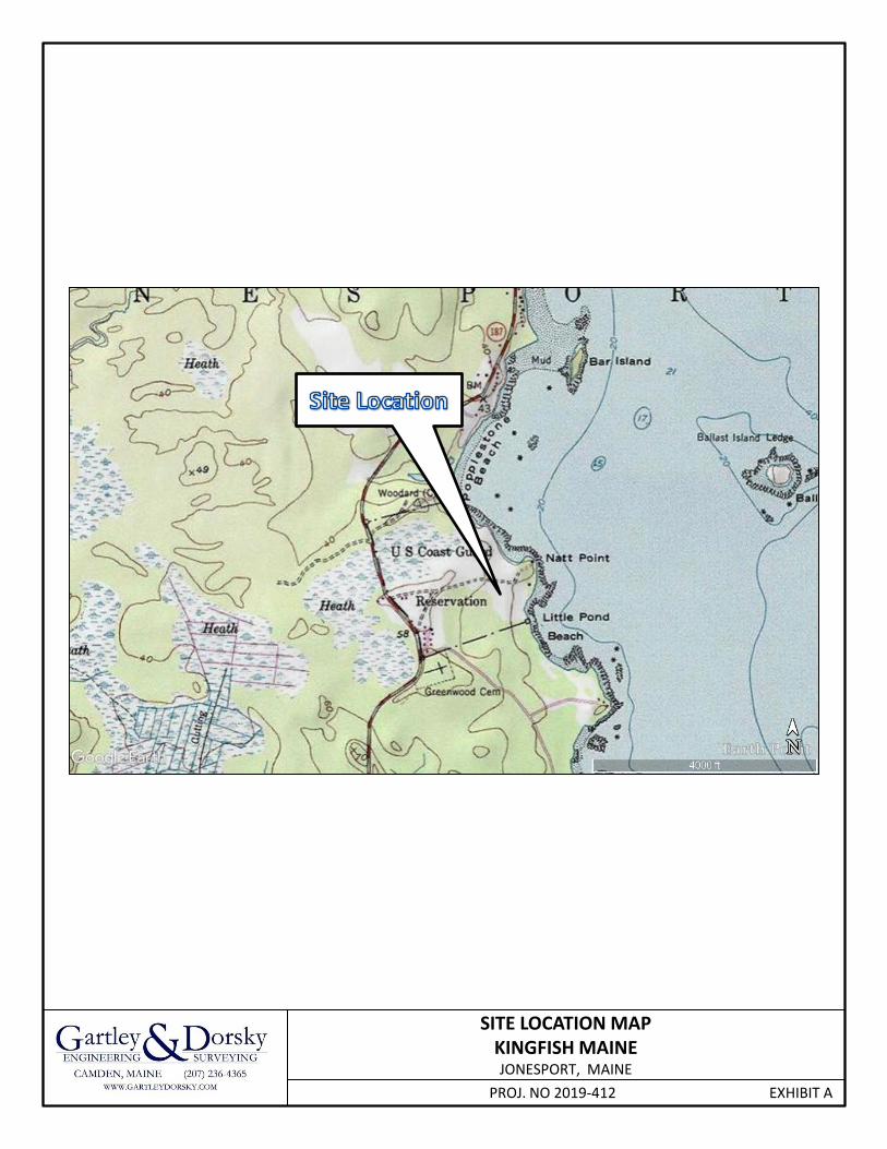
SITE LOCATION MAPKINGFISH MAINEJONESPORT, MAINE
PROJ. NO 2019-412 EXHIBIT A

KINGFISH MAINE, INC. ENGINEERED SUBSURFACE WASTEWATER SYSTEM
EXHIBIT B & C
Mounding Analysis & Transmissivity Analysis

____________________________________________________________________________________________________ 59 Union Street Unit 1 PO Box 1031 Camden, ME 04843 Ph (207) 236-4365 Fax (207) 236-3055 www.gartleydorsky.com
March 20, 2021 Megan Sorby Tom Sorby Kingfish Maine, Inc. 33 Salmon Farm Road Franklin, ME 04 RE: Subsurface Wastewater Disposal System 1 – Mounding Analysis Project 2019-412 Kingfish Maine RAS Facility Dear Megan and Tom: We have completed a Mounding Analysis for the proposed primary wastewater disposal system at Kingfish Maine in Jonesport, Maine. The proposed system is are designated as Disposal Field 1 on the site plan enclosed. We also include copies of test pit logs with soil profile information. The design flow for the systems is 4,000 gallons per day (gpd) which will be split between two discrete sections of the disposal field. The disposal fields sections are each 31 X 56 feet in size and utilize Eljen GSF standard modules arranged in 8 rows of 14 modules (total 224 units). The mounding calculations are derived from the United States Geological Survey (USGS) Scientific Investigation Report 2010-5102. The analytical model is based on a Solution to the Hantush Equation (1967). Input parameters to the model include recharge rate, specific yield, initial saturated thickness of the aquifer, field size, time and horizontal hydraulic conductivity. The values used for each input parameter are as follows: The per field recharge rate is 0.154 feet per day based on 2,000 gpd (267 cubic feet per day) design flow and a field size of 1,736 square feet. The recharge rate is considered constant. If actual design flow is less, mounding predictions would be lower than predicted. Specific yield is 0.26 (dimensionless) and reflects the ability of a soil to drain water and is a ratio of the volume of water that drains from a unit volume of the soil compared to the volume of soil. Reference values were derived from US Department of the Interior Geological Survey Water Supply Paper 1662-D. Initial saturated thickness of the aquifer is on the order of 22 feet. These values are derived from the exploration data. Test pits (Nos. 16 to 21) encountered no limiting bedrock condition at depths of 34”. In the adjacent geotechnical investigation’s boring (B15), depth to bedrock in field was generally greater than 23 feet. In general, overburden in this section of the property is consistent with this finding. As a result, overburden is conservatively assigned to be 20 feet thick in the vicinity of the disposal field.

Kingfish Maine Subsurface Wastewater Disposal System 1 - Mounding
Page 2 of 3
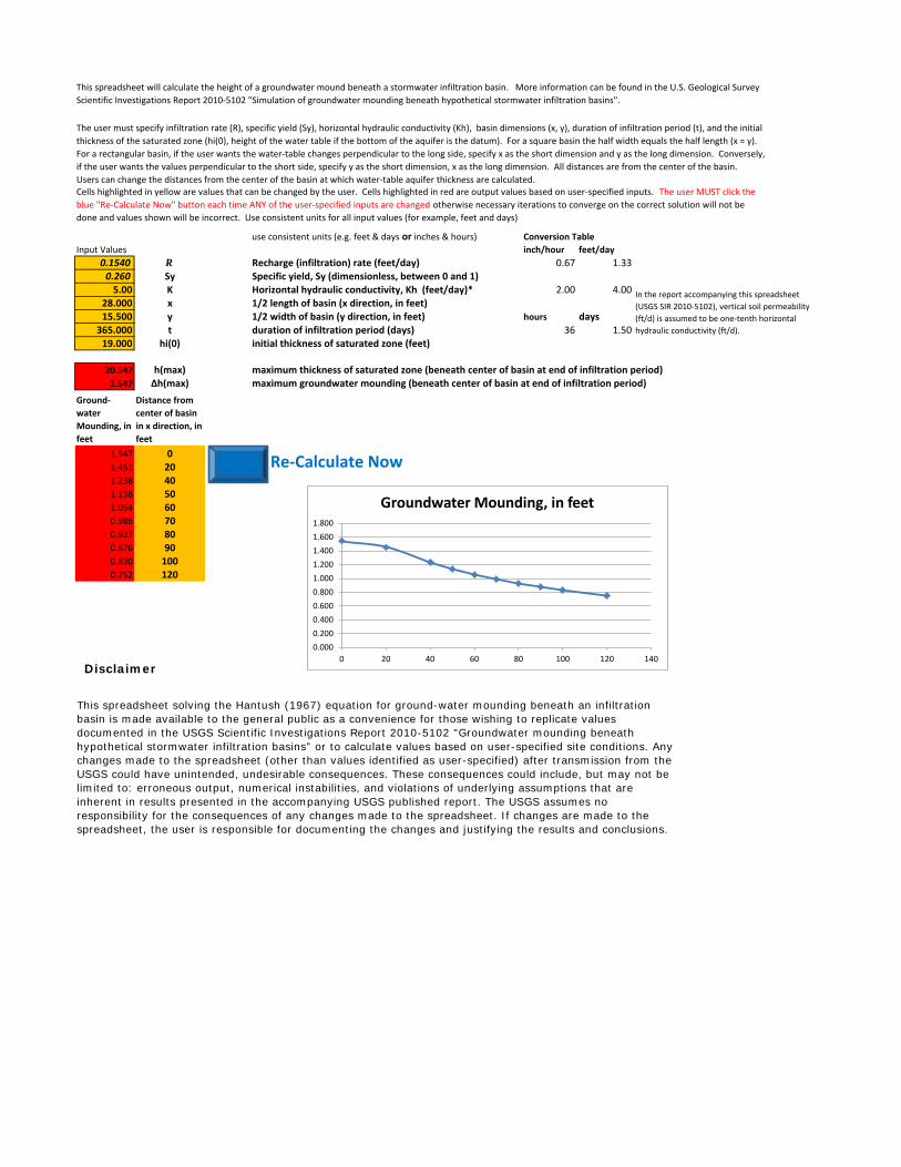
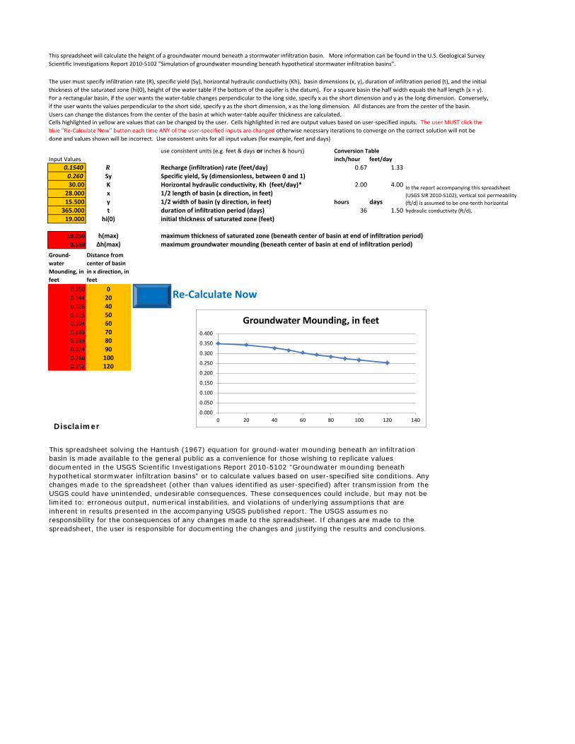
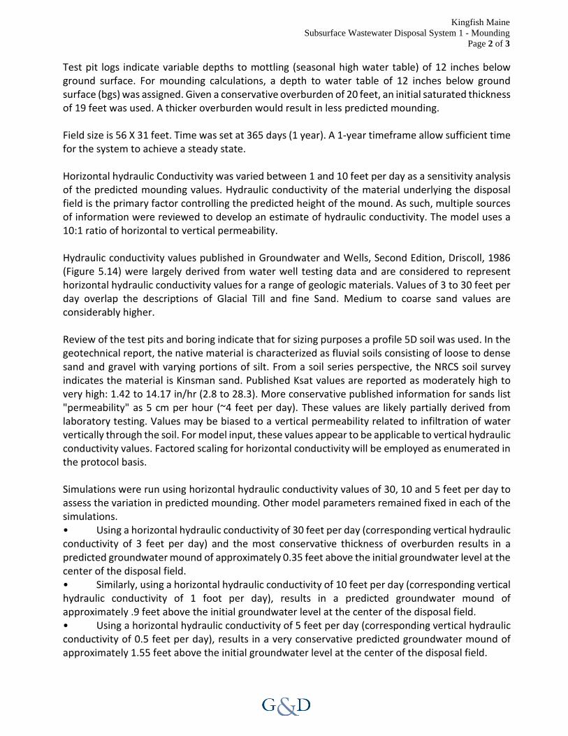
Test pit logs indicate variable depths to mottling (seasonal high water table) of 12 inches below ground surface. For mounding calculations, a depth to water table of 12 inches below ground surface (bgs) was assigned. Given a conservative overburden of 20 feet, an initial saturated thickness of 19 feet was used. A thicker overburden would result in less predicted mounding. Field size is 56 X 31 feet. Time was set at 365 days (1 year). A 1-year timeframe allow sufficient time for the system to achieve a steady state. Horizontal hydraulic Conductivity was varied between 1 and 10 feet per day as a sensitivity analysis of the predicted mounding values. Hydraulic conductivity of the material underlying the disposal field is the primary factor controlling the predicted height of the mound. As such, multiple sources of information were reviewed to develop an estimate of hydraulic conductivity. The model uses a 10:1 ratio of horizontal to vertical permeability. Hydraulic conductivity values published in Groundwater and Wells, Second Edition, Driscoll, 1986 (Figure 5.14) were largely derived from water well testing data and are considered to represent horizontal hydraulic conductivity values for a range of geologic materials. Values of 3 to 30 feet per day overlap the descriptions of Glacial Till and fine Sand. Medium to coarse sand values are considerably higher. Review of the test pits and boring indicate that for sizing purposes a profile 5D soil was used. In the geotechnical report, the native material is characterized as fluvial soils consisting of loose to dense sand and gravel with varying portions of silt. From a soil series perspective, the NRCS soil survey indicates the material is Kinsman sand. Published Ksat values are reported as moderately high to very high: 1.42 to 14.17 in/hr (2.8 to 28.3). More conservative published information for sands list "permeability" as 5 cm per hour (~4 feet per day). These values are likely partially derived from laboratory testing. Values may be biased to a vertical permeability related to infiltration of water vertically through the soil. For model input, these values appear to be applicable to vertical hydraulic conductivity values. Factored scaling for horizontal conductivity will be employed as enumerated in the protocol basis. Simulations were run using horizontal hydraulic conductivity values of 30, 10 and 5 feet per day to assess the variation in predicted mounding. Other model parameters remained fixed in each of the simulations. • Using a horizontal hydraulic conductivity of 30 feet per day (corresponding vertical hydraulic conductivity of 3 feet per day) and the most conservative thickness of overburden results in a predicted groundwater mound of approximately 0.35 feet above the initial groundwater level at the center of the disposal field. • Similarly, using a horizontal hydraulic conductivity of 10 feet per day (corresponding vertical hydraulic conductivity of 1 foot per day), results in a predicted groundwater mound of approximately .9 feet above the initial groundwater level at the center of the disposal field. • Using a horizontal hydraulic conductivity of 5 feet per day (corresponding vertical hydraulic conductivity of 0.5 feet per day), results in a very conservative predicted groundwater mound of approximately 1.55 feet above the initial groundwater level at the center of the disposal field.
Kingfish Maine Subsurface Wastewater Disposal System 1 - Mounding
Page 3 of 3
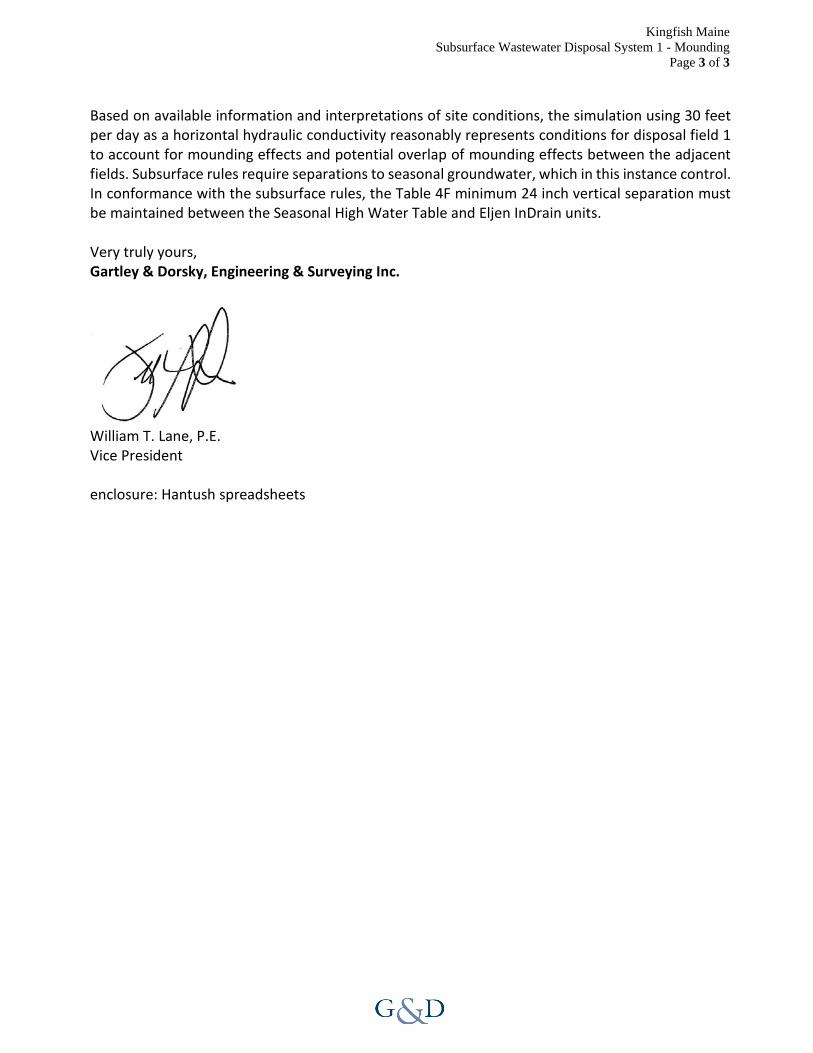
Based on available information and interpretations of site conditions, the simulation using 30 feet per day as a horizontal hydraulic conductivity reasonably represents conditions for disposal field 1 to account for mounding effects and potential overlap of mounding effects between the adjacent fields. Subsurface rules require separations to seasonal groundwater, which in this instance control. In conformance with the subsurface rules, the Table 4F minimum 24 inch vertical separation must be maintained between the Seasonal High Water Table and Eljen InDrain units. Very truly yours, Gartley & Dorsky, Engineering & Surveying Inc.
William T. Lane, P.E. Vice President enclosure: Hantush spreadsheets
use consistent units (e.g. feet & days or inches & hours) Conversion Table
Input Values inch/hour feet/day
0.1540 R Recharge (infiltration) rate (feet/day) 0.67 1.330.260 Sy Specific yield, Sy (dimensionless, between 0 and 1)5.00 K Horizontal hydraulic conductivity, Kh (feet/day)* 2.00 4.00
28.000 x 1/2 length of basin (x direction, in feet)15.500 y 1/2 width of basin (y direction, in feet) hours days
365.000 t duration of infiltration period (days) 36 1.5019.000 hi(0) initial thickness of saturated zone (feet)
20.547 h(max) maximum thickness of saturated zone (beneath center of basin at end of infiltration period)1.547 Δh(max) maximum groundwater mounding (beneath center of basin at end of infiltration period)
Ground‐
water
Mounding, in
feet
Distance from
center of basin
in x direction, in
feet
1.547 01.451 201.238 401.138 501.054 600.986 700.927 800.876 900.830 1000.752 120
Disclaimer
This spreadsheet solving the Hantush (1967) equation for ground-water mounding beneath an infiltration basin is made available to the general public as a convenience for those wishing to replicate values documented in the USGS Scientific Investigations Report 2010-5102 "Groundwater mounding beneath hypothetical stormwater infiltration basins" or to calculate values based on user-specified site conditions. Any changes made to the spreadsheet (other than values identified as user-specified) after transmission from the USGS could have unintended, undesirable consequences. These consequences could include, but may not be limited to: erroneous output, numerical instabilities, and violations of underlying assumptions that are inherent in results presented in the accompanying USGS published report. The USGS assumes no responsibility for the consequences of any changes made to the spreadsheet. If changes are made to the spreadsheet, the user is responsible for documenting the changes and justifying the results and conclusions.
This spreadsheet will calculate the height of a groundwater mound beneath a stormwater infiltration basin. More information can be found in the U.S. Geological Survey
Scientific Investigations Report 2010‐5102 "Simulation of groundwater mounding beneath hypothetical stormwater infiltration basins".
The user must specify infiltration rate (R), specific yield (Sy), horizontal hydraulic conductivity (Kh), basin dimensions (x, y), duration of infiltration period (t), and the initial
thickness of the saturated zone (hi(0), height of the water table if the bottom of the aquifer is the datum). For a square basin the half width equals the half length (x = y).
For a rectangular basin, if the user wants the water‐table changes perpendicular to the long side, specify x as the short dimension and y as the long dimension. Conversely,
if the user wants the values perpendicular to the short side, specify y as the short dimension, x as the long dimension. All distances are from the center of the basin.
Users can change the distances from the center of the basin at which water‐table aquifer thickness are calculated.Cells highlighted in yellow are values that can be changed by the user. Cells highlighted in red are output values based on user‐specified inputs. The user MUST click the
blue "Re‐Calculate Now" button each time ANY of the user‐specified inputs are changed otherwise necessary iterations to converge on the correct solution will not be
done and values shown will be incorrect. Use consistent units for all input values (for example, feet and days)
In the report accompanying this spreadsheet
(USGS SIR 2010‐5102), vertical soil permeability
(ft/d) is assumed to be one‐tenth horizontal
hydraulic conductivity (ft/d).
Re‐Calculate Now
0.000
0.200
0.400
0.600
0.800
1.000
1.200
1.400
1.600
1.800
0 20 40 60 80 100 120 140
Groundwater Mounding, in feet

use consistent units (e.g. feet & days or inches & hours) Conversion Table
Input Values inch/hour feet/day
0.1540 R Recharge (infiltration) rate (feet/day) 0.67 1.330.260 Sy Specific yield, Sy (dimensionless, between 0 and 1)10.00 K Horizontal hydraulic conductivity, Kh (feet/day)* 2.00 4.00
28.000 x 1/2 length of basin (x direction, in feet)15.500 y 1/2 width of basin (y direction, in feet) hours days
365.000 t duration of infiltration period (days) 36 1.5019.000 hi(0) initial thickness of saturated zone (feet)
19.862 h(max) maximum thickness of saturated zone (beneath center of basin at end of infiltration period)0.862 Δh(max) maximum groundwater mounding (beneath center of basin at end of infiltration period)
Ground‐
water
Mounding, in
feet
Distance from
center of basin
in x direction, in
feet
0.862 00.822 200.732 400.686 500.644 600.608 700.578 800.552 900.529 1000.489 120
Disclaimer
This spreadsheet solving the Hantush (1967) equation for ground-water mounding beneath an infiltration basin is made available to the general public as a convenience for those wishing to replicate values documented in the USGS Scientific Investigations Report 2010-5102 "Groundwater mounding beneath hypothetical stormwater infiltration basins" or to calculate values based on user-specified site conditions. Any changes made to the spreadsheet (other than values identified as user-specified) after transmission from the USGS could have unintended, undesirable consequences. These consequences could include, but may not be limited to: erroneous output, numerical instabilities, and violations of underlying assumptions that are inherent in results presented in the accompanying USGS published report. The USGS assumes no responsibility for the consequences of any changes made to the spreadsheet. If changes are made to the spreadsheet, the user is responsible for documenting the changes and justifying the results and conclusions.
This spreadsheet will calculate the height of a groundwater mound beneath a stormwater infiltration basin. More information can be found in the U.S. Geological Survey
Scientific Investigations Report 2010‐5102 "Simulation of groundwater mounding beneath hypothetical stormwater infiltration basins".
The user must specify infiltration rate (R), specific yield (Sy), horizontal hydraulic conductivity (Kh), basin dimensions (x, y), duration of infiltration period (t), and the initial
thickness of the saturated zone (hi(0), height of the water table if the bottom of the aquifer is the datum). For a square basin the half width equals the half length (x = y).
For a rectangular basin, if the user wants the water‐table changes perpendicular to the long side, specify x as the short dimension and y as the long dimension. Conversely,
if the user wants the values perpendicular to the short side, specify y as the short dimension, x as the long dimension. All distances are from the center of the basin.
Users can change the distances from the center of the basin at which water‐table aquifer thickness are calculated.Cells highlighted in yellow are values that can be changed by the user. Cells highlighted in red are output values based on user‐specified inputs. The user MUST click the
blue "Re‐Calculate Now" button each time ANY of the user‐specified inputs are changed otherwise necessary iterations to converge on the correct solution will not be
done and values shown will be incorrect. Use consistent units for all input values (for example, feet and days)
In the report accompanying this spreadsheet
(USGS SIR 2010‐5102), vertical soil permeability
(ft/d) is assumed to be one‐tenth horizontal
hydraulic conductivity (ft/d).
Re‐Calculate Now
0.000
0.100
0.200
0.300
0.400
0.500
0.600
0.700
0.800
0.900
1.000
0 20 40 60 80 100 120 140
Groundwater Mounding, in feet
use consistent units (e.g. feet & days or inches & hours) Conversion Table
Input Values inch/hour feet/day
0.1540 R Recharge (infiltration) rate (feet/day) 0.67 1.330.260 Sy Specific yield, Sy (dimensionless, between 0 and 1)30.00 K Horizontal hydraulic conductivity, Kh (feet/day)* 2.00 4.00
28.000 x 1/2 length of basin (x direction, in feet)15.500 y 1/2 width of basin (y direction, in feet) hours days
365.000 t duration of infiltration period (days) 36 1.5019.000 hi(0) initial thickness of saturated zone (feet)
19.350 h(max) maximum thickness of saturated zone (beneath center of basin at end of infiltration period)0.350 Δh(max) maximum groundwater mounding (beneath center of basin at end of infiltration period)
Ground‐
water
Mounding, in
feet
Distance from
center of basin
in x direction, in
feet
0.350 00.344 200.326 400.315 500.304 600.293 700.283 800.274 900.266 1000.252 120
Disclaimer
This spreadsheet solving the Hantush (1967) equation for ground-water mounding beneath an infiltration basin is made available to the general public as a convenience for those wishing to replicate values documented in the USGS Scientific Investigations Report 2010-5102 "Groundwater mounding beneath hypothetical stormwater infiltration basins" or to calculate values based on user-specified site conditions. Any changes made to the spreadsheet (other than values identified as user-specified) after transmission from the USGS could have unintended, undesirable consequences. These consequences could include, but may not be limited to: erroneous output, numerical instabilities, and violations of underlying assumptions that are inherent in results presented in the accompanying USGS published report. The USGS assumes no responsibility for the consequences of any changes made to the spreadsheet. If changes are made to the spreadsheet, the user is responsible for documenting the changes and justifying the results and conclusions.
This spreadsheet will calculate the height of a groundwater mound beneath a stormwater infiltration basin. More information can be found in the U.S. Geological Survey
Scientific Investigations Report 2010‐5102 "Simulation of groundwater mounding beneath hypothetical stormwater infiltration basins".
The user must specify infiltration rate (R), specific yield (Sy), horizontal hydraulic conductivity (Kh), basin dimensions (x, y), duration of infiltration period (t), and the initial
thickness of the saturated zone (hi(0), height of the water table if the bottom of the aquifer is the datum). For a square basin the half width equals the half length (x = y).
For a rectangular basin, if the user wants the water‐table changes perpendicular to the long side, specify x as the short dimension and y as the long dimension. Conversely,
if the user wants the values perpendicular to the short side, specify y as the short dimension, x as the long dimension. All distances are from the center of the basin.
Users can change the distances from the center of the basin at which water‐table aquifer thickness are calculated.Cells highlighted in yellow are values that can be changed by the user. Cells highlighted in red are output values based on user‐specified inputs. The user MUST click the
blue "Re‐Calculate Now" button each time ANY of the user‐specified inputs are changed otherwise necessary iterations to converge on the correct solution will not be
done and values shown will be incorrect. Use consistent units for all input values (for example, feet and days)
In the report accompanying this spreadsheet
(USGS SIR 2010‐5102), vertical soil permeability
(ft/d) is assumed to be one‐tenth horizontal
hydraulic conductivity (ft/d).
Re‐Calculate Now
0.000
0.050
0.100
0.150
0.200
0.250
0.300
0.350
0.400
0 20 40 60 80 100 120 140
Groundwater Mounding, in feet

KINGFISH MAINE, INC. ENGINEERED SUBSURFACE WASTEWATER SYSTEM
EXHIBIT D
HHE200 Form

33 SALMON FARM ROADFRANKLIN, ME 04634
(502) 387-8673 8 23
± 93.2
12,000
5 D16-21
12
224 ELJEN GSF MODULES
4(TOTAL 16 BEDROOMS)AQUACULTURE
4000
44 33 19.967 34 18.0
(207) 236-4365
16 BEDROOM (4 UNITS) @ 90 GPD128 EMPLOYEES WITH SHOWER @ 20 GPD
PER EMPLOYEE
11/23/20
Maine Dept. Health & Human Services
Division of Health Engineering, 10 SHS
(207) 287-2070 Fax: (207) 287-4172
City, Town,
or Plantation
>> CAUTION: LPI APPROVAL REQUIRED <<
SUBSURFACE WASTEWATER DISPOSAL SYSTEM APPLICATION
PROPERTY LOCATION
OWNER/APPLICANT INFORMATION
OWNER OR APPLICANT STATEMENT
I state and acknowledge that the information submitted is correct to the best of
my knowledge and understand that any falsification is reason for the Department
and/or Local Plumbing Inspector to deny a Permit.
__________ __________________________________ __________
Signature of Owner or Applicant Date
Street or Road
Subdivision, Lot #
Name (last, first, MI)
Owner
Applicant
Mailing Address
of
Owner/Applicant
Daytime Tel. #
THIS APPLICATION REQUIRES
1. No Rule Variance
2. First Time System Variance
3. Replacement System Variance
4. Minimum Lot Size Variance
5. Seasonal Conversion Permit
a. Local Plumbing Inspector Approval
b. State & Local Plumbing Inspector Approval
a. Local Plumbing Inspector Approval
b. State & Local Plumbing Inspector Approval
PERMIT INFORMATION
SITE EVALUATOR STATEMENT
DESIGN DETAILS (SYSTEM LAYOUT SHOWN ON PAGE 3)
DISPOSAL SYSTEM COMPONENTS
1. Complete Non-engineered System
2. Primitive System (graywater & alt. toilet)
3. Alternative Toilet, specify:____________
4. Non-engineered Treatment Tank (only)
5. Holding Tank, _______ gallons
6. Non-engineered Disposal Field (only)
7. Separated Laundry System
8. Complete Engineered System (2000 gpd or more)
9. Engineered Treatment Tank (only)
10. Engineered Disposal Field (only)
11. Pre-treatment, specify: _________
12. Miscellaneous Components
TYPE OF APPLICATION
1. First Time System
2. Replacement System
Type replaced: ______________
Year installed: ______________
3. Expanded System
a. <25% Expansion
b. ≥25% Expansion
4. Experimental System
5. Seasonal Conversion
SIZE OF PROPERTY
SQ. FT.
ACRES
SHORELAND ZONING
Yes No
DISPOSAL SYSTEM TO SERVE
1. Single Family Dwelling Unit, No. of Bedrooms: ____
2. Multiple Family Dwelling, No. of Units: _____
3. Other: __________________________
(specify)
Current Use Seasonal Year Round Undeveloped
EFFLUENT/EJECTOR PUMP
1. Not Required
2. May Be Required
3. Required
Specify only for engineered systems:
DOSE: __________ gallons
TREATMENT TANK
1. Concrete
a. Regular
b. Low Profile
2. Plastic
3. Other: ________________
CAPACITY: _________ GAL.
DISPOSAL FIELD TYPE & SIZE
1. Stone Bed 2. Stone Trench
3. Proprietary Device
a. cluster array c. Linear
b. regular load d. H-20 load
4. Other: _____________________
SIZE: ___________ sq. ft. lin. ft.
type: _____________________
GARBAGE DISPOSAL UNIT
1. No 2. Yes 3. Maybe
If Yes or Maybe, specify one below:
a. multi-compartment tank
b. ___ tanks in series
c. increase in tank capacity
d. Filter on Tank Outlet
SOIL DATA & DESIGN CLASS
PROFILE CONDITION
_______/___________
at Observation Hole #________
Depth _____"
of Most Limiting Soil Factor
DISPOSAL FIELD SIZING
1. Medium---2.6 sq. ft. / gpd
2. Medium---Large 3.3 sq. f.t / gpd
3. Large---4.1 sq. ft. / gpd
4. Extra Large---5.0 sq. ft. / gpd
DESIGN FLOW
_______________ gallons per day
BASED ON:
1. Table 4A (dwelling unit(s))
2. Table 4C (other facilities)
SHOW CALCULATIONS for other facilities
3. Section 4G (meter readings)
ATTACH WATER METER DATA
LATITUDE AND LONGITUDE
at center of disposal area
Lat. _______d _______m _______s
Lon. _______d _______m _______s
if g.p.s, state margin of error:_____________
I certify that on ____________ (date) I completed a site evaluation on this property and state that the data reported are accurate and
that the proposed system is in compliance with the State of Maine Subsurface Wastewater Disposal Rules (10-144A CMR 241).
__________ ____________________________ ____________________ _______________
Site Evaluator Signature SE # Date
______________________________________________ ________________ __________________________________
Site Evaluator Name Printed Telephone Number E-mail Address
HHE-200 Rev. 11/2013
Note: Changes to or deviations from the design should be confirmed with the Site Evaluator.
TYPE OF WATER SUPPLY
1. Drilled Well 2. Dug Well 3. Private
4. Public 5. Other
GARTLEY & DORSKYENGINEERING & SURVEYING
H:\Land Projects 3\19412 Kingfish\Drawings\Septic Designs\19412 HHE200.dwg
CAUTION: INSPECTION REQUIRED
I have inspected the installation authorized above and found it to be in compliance
with the Subsurface Wastewater Disposal Rules Application. _________________
(1st) date approved
__________________________________________ _______________________
Local Plumbing Inspector Signature (2nd) date approved
The Subsurface Wastewater Disposal System shall not be installed until a
Permit is issued by the Local Plumbing Inspector. The Permit shall
authorize the owner or installer to install the disposal system in accordance
with this application and the Maine Subsurface Wastewater Disposal Rules.
Town/City ____________________________ Permit # ___________
Date Permit Issued ___/___/___ Fee: $__________ Double Fee Charged [ ]
_____________________________________________ L.P.I. # ______________
Local Plumbing Inspector Signature
Municipal Tax Map # ____________ Lot # _________
Fee: $_________ state min fee $_________Locally adopted
fee copy [ ] Owner [ ] Town [ ] State
JONESPORT
DUN GARVIN ROAD
3/25/21
KINGFISH MAINE, INC.
Natalie Marceau ( )
411
PROJ. NO.: 2019-412
PROPOSED
(3) 4,000 GAL
SUBSURFACE WASTEWATER DISPOSAL SYSTEM APPLICATION
Town, City, Plantation Street, Road, Subdivision
Department of Human Services
Division of Health Engineering
(207) 287-5672 Fax: (207) 287-3165
Owner's Name
SUBSURFACE WASTEWATER DISPOSAL PLANSCALE: 1" = ___________FT.
Site Evaluator Signature SE # Date
FILL REQUIREMENTS
Depth of Fill (Upslope) __________
Depth of Fill (Downslope) __________
CONSTRUCTION ELEVATIONSFinished Grade Elevation _______Top of Distribution Pipe or Proprietary Device _______Bottom of Disposal Area _______
ELEVATION REFERENCE POINTLocation & Description:
Reference Elevation: ____________ SCALEHorizontal 1" = _____ ft.Vertical 1" = _____ ft.
DISPOSAL AREA CROSS SECTION
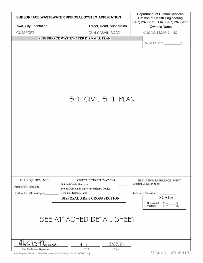
JONESPORT DUN GARVIN ROAD KINGFISH MAINE, INC.
3/25/21411
H:\Land Projects 3\19412 Kingfish\Drawings\Septic Designs\19412 HHE200.dwg PROJ. NO.: 2019-412
SEE CIVIL SITE PLAN
SEE ATTACHED DETAIL SHEET

KINGFISH MAINE, INC. ENGINEERED SUBSURFACE WASTEWATER SYSTEM
EXHIBIT E
Operations & Maintenance Manual
KINGFISH MAINE Engineered Septic System
Operation and Maintenance Manual
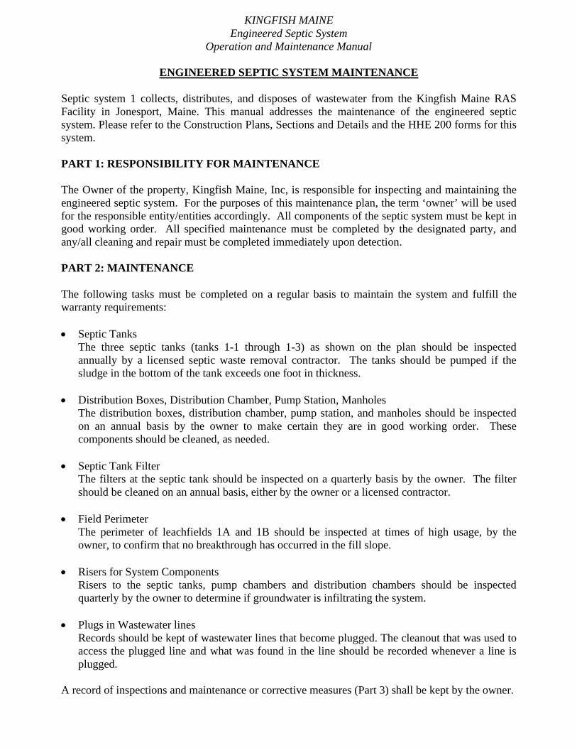
ENGINEERED SEPTIC SYSTEM MAINTENANCE Septic system 1 collects, distributes, and disposes of wastewater from the Kingfish Maine RAS Facility in Jonesport, Maine. This manual addresses the maintenance of the engineered septic system. Please refer to the Construction Plans, Sections and Details and the HHE 200 forms for this system. PART 1: RESPONSIBILITY FOR MAINTENANCE The Owner of the property, Kingfish Maine, Inc, is responsible for inspecting and maintaining the engineered septic system. For the purposes of this maintenance plan, the term ‘owner’ will be used for the responsible entity/entities accordingly. All components of the septic system must be kept in good working order. All specified maintenance must be completed by the designated party, and any/all cleaning and repair must be completed immediately upon detection. PART 2: MAINTENANCE The following tasks must be completed on a regular basis to maintain the system and fulfill the warranty requirements: • Septic Tanks
The three septic tanks (tanks 1-1 through 1-3) as shown on the plan should be inspected annually by a licensed septic waste removal contractor. The tanks should be pumped if the sludge in the bottom of the tank exceeds one foot in thickness.
• Distribution Boxes, Distribution Chamber, Pump Station, Manholes The distribution boxes, distribution chamber, pump station, and manholes should be inspected on an annual basis by the owner to make certain they are in good working order. These components should be cleaned, as needed.
• Septic Tank Filter The filters at the septic tank should be inspected on a quarterly basis by the owner. The filter should be cleaned on an annual basis, either by the owner or a licensed contractor.
• Field Perimeter The perimeter of leachfields 1A and 1B should be inspected at times of high usage, by the owner, to confirm that no breakthrough has occurred in the fill slope.
• Risers for System Components Risers to the septic tanks, pump chambers and distribution chambers should be inspected quarterly by the owner to determine if groundwater is infiltrating the system.
• Plugs in Wastewater lines Records should be kept of wastewater lines that become plugged. The cleanout that was used to access the plugged line and what was found in the line should be recorded whenever a line is plugged.
A record of inspections and maintenance or corrective measures (Part 3) shall be kept by the owner.

KINGFISH MAINE Engineered Septic System
Operation and Maintenance Manual PART 3: RECORD KEEPING The owner shall inspect and maintain the septic system as required by the following tables below. Any maintenance or inspections that are not performed puts the system at risk for failure. A maintenance contract shall be signed to maintain the components of the system that requires the expertise of a professional who understands the function of each system component as shown below.
Engineered septic System MAINTENANCE LOG
How to Complete:
1. Complete the specified maintenance on the prescribed frequency 2. Initial all areas that are satisfactory or initial performed maintenance 3. Note any deficiencies or required maintenance items 4. Maintain this record on file for DHHS review, as requested 5. Contact Gartley & Dorsky for additional copies of these Maintenance Logs
MAINTENANCE TASKS
Work Task Frequency By Whom Date & Initials
Date & Initials
Date & Initials
Date & Initials
Inspect Septic Tanks Annually Licensed Septic Tank Contractor
Pump Septic Tanks When sludge level exceeds 1’ thick
Licensed Septic Tank Contractor
Inspect Septic Tanks Filters Quarterly Owner
Replace Septic Tanks Filters As needed
(annually at minimum)
Owner or Licensed Septic Tank Contractor
Inspect the Grease Trap Semi-annual Owner or Licensed Septic Tank Contractor
Keep Records of plugged wastewater lines As needed Owner and Septic Tank
Contractor
Inspect Distribution Boxes and drop boxes Annually Owner
Risers to septic tanks, pump stations and distribution
chambers Quarterly Owner
Inspect Field Perimeter Time of high usage Owner
Inspect for Potential Erosion or Crushing Problems As Needed Owner
Notes: Gartley & Dorsky Engineering & Surveying shall be notified of any changes that affect design conditions. REVIEWED AND ACKNOWLEDGED BY OWNER: BY:

KINGFISH MAINE Engineered Septic System
Operation and Maintenance Manual CONTACTS DESIGN/INSPECTION William Lane, P.E. Vice President Gartley & Dorsky Engineering & Surveying PO Box 1031 Camden, ME 04843 Tel: 207.236.4365 Fax: 207.236.3055 Email: [email protected] Web: http://www.gartleydorsky.com SITE EVALUATOR Natalie Marceau Gartley & Dorsky Engineering & Surveying PO Box 1031 Camden, ME 04843 Tel: 207.236.4365 Fax: 207.236.3055 Email: [email protected] Web: http://www.gartleydorsky.com EARTHWORK CONTRACTOR/INSTALLER TBD

KINGFISH MAINE, INC. ENGINEERED SUBSURFACE WASTEWATER SYSTEM
EXHIBIT F
Soil & Site Conditions

SUBSURFACE WASTEWATER DISPOSAL SYSTEM APPLICATION
Town, City, Plantation Street, Road, Subdivision
Department of Human Services
Division of Health Engineering
(207) 287-5672 Fax: (207) 287-3165
Owner's Name
SOIL DESCRIPTION AND CLASSIFICATION
Site Evaluator Signature SE # Date
SOIL DESCRIPTION AND CLASSIFICATION
Observation Hole _______ Test Pit Boring________ " Depth of Organic Horizon Above Mineral Soil
Observation Hole _______ Test Pit Boring________ " Depth of Organic Horizon Above Mineral Soil
Dep
th B
elow
Min
eral
Soi
l Sur
face
(inc
hes)
Soil Classification Slope Limiting [ ] Ground Water Factor [ ] Restrictive Layer_______ ________ ______ % [ ] Bedrock Profile Condition _____" [ ] Pit Depth
Soil Classification Slope Limiting [ ] Ground Water Factor [ ] Restrictive Layer_______ ________ ______ % [ ] Bedrock Profile Condition _____" [ ] Pit Depth
Texture MottlingConsistency Color Texture MottlingConsistency Color
Dep
th B
elow
Min
eral
Soi
l Sur
face
(inc
hes)
Observation Hole _______ Test Pit Boring________ " Depth of Organic Horizon Above Mineral Soil
Observation Hole _______ Test Pit Boring________ " Depth of Organic Horizon Above Mineral Soil
Dep
th B
elow
Min
eral
Soi
l Sur
face
(inc
hes)
Soil Classification Slope Limiting [ ] Ground Water Factor [ ] Restrictive Layer_______ ________ ______ % [ ] Bedrock Profile Condition _____" [ ] Pit Depth
Soil Classification Slope Limiting [ ] Ground Water Factor [ ] Restrictive Layer_______ ________ ______ % [ ] Bedrock Profile Condition _____" [ ] Pit Depth
Texture MottlingConsistency Color Texture MottlingConsistency Color
Dep
th B
elow
Min
eral
Soi
l Sur
face
(inc
hes)
JONESPORT DUN GARVAN ROAD KINGFISH MAINE, INC.
3/25/21
191
411
H:\Land Projects 3\19412 Kingfish\Drawings\Septic Designs\19412 TP data.dwg PROJ. NO.: 2019-412
5 D ±312
FRIABLE
DARKBROWN NONELOAMY
SAND
STRONGBROWN
YELLOWISHBROWNSAND
COMMONMEDIUMDISTINCTSTRONGBROWN
161
5 D ±312
FRIABLE
DARKBROWN NONELOAMY
SAND
STRONGBROWN
YELLOWISHBROWNSAND
COMMONMEDIUMDISTINCTSTRONGBROWN
171
5 D ±312
FRIABLE
DARKBROWN NONELOAMY
SAND
STRONGBROWN
YELLOWISHBROWNSAND
COMMONMEDIUMDISTINCTSTRONGBROWN
181
5 D ±312
FRIABLE
DARKBROWN NONELOAMY
SAND
STRONGBROWN
YELLOWISHBROWNSAND
COMMONMEDIUMDISTINCTSTRONGBROWN
BOTTOM OF TEST PIT BOTTOM OF TEST PIT
BOTTOM OF TEST PIT BOTTOM OF TEST PIT

SUBSURFACE WASTEWATER DISPOSAL SYSTEM APPLICATION
Town, City, Plantation Street, Road, Subdivision
Department of Human Services
Division of Health Engineering
(207) 287-5672 Fax: (207) 287-3165
Owner's Name
SOIL DESCRIPTION AND CLASSIFICATION
Site Evaluator Signature SE # Date
SOIL DESCRIPTION AND CLASSIFICATION
Observation Hole _______ Test Pit Boring________ " Depth of Organic Horizon Above Mineral Soil
Observation Hole _______ Test Pit Boring________ " Depth of Organic Horizon Above Mineral Soil
Dep
th B
elow
Min
eral
Soi
l Sur
face
(inc
hes)
Soil Classification Slope Limiting [ ] Ground Water Factor [ ] Restrictive Layer_______ ________ ______ % [ ] Bedrock Profile Condition _____" [ ] Pit Depth
Soil Classification Slope Limiting [ ] Ground Water Factor [ ] Restrictive Layer_______ ________ ______ % [ ] Bedrock Profile Condition _____" [ ] Pit Depth
Texture MottlingConsistency Color Texture MottlingConsistency Color
Dep
th B
elow
Min
eral
Soi
l Sur
face
(inc
hes)
Observation Hole _______ Test Pit Boring________ " Depth of Organic Horizon Above Mineral Soil
Observation Hole _______ Test Pit Boring________ " Depth of Organic Horizon Above Mineral Soil
Dep
th B
elow
Min
eral
Soi
l Sur
face
(inc
hes)
Soil Classification Slope Limiting [ ] Ground Water Factor [ ] Restrictive Layer_______ ________ ______ % [ ] Bedrock Profile Condition _____" [ ] Pit Depth
Soil Classification Slope Limiting [ ] Ground Water Factor [ ] Restrictive Layer_______ ________ ______ % [ ] Bedrock Profile Condition _____" [ ] Pit Depth
Texture MottlingConsistency Color Texture MottlingConsistency Color
Dep
th B
elow
Min
eral
Soi
l Sur
face
(inc
hes)
JONESPORT DUN GARVAN ROAD KINGFISH MAINE, INC.
3/25/21
231
411
H:\Land Projects 3\19412 Kingfish\Drawings\Septic Designs\19412 TP data.dwg PROJ. NO.: 2019-412
5 D ±312
FRIABLE
DARKBROWN NONELOAMY
SAND
STRONGBROWN
YELLOWISHBROWNSAND
COMMONMEDIUMDISTINCTSTRONGBROWN
201
5 D ±312
FRIABLE
DARKBROWN NONELOAMY
SAND
STRONGBROWN
YELLOWISHBROWNSAND
COMMONMEDIUMDISTINCTSTRONGBROWN
211
5 D ±312
FRIABLE
DARKBROWN NONELOAMY
SAND
STRONGBROWN
YELLOWISHBROWNSAND
COMMONMEDIUMDISTINCTSTRONGBROWN
221
5 D ±312
FRIABLE
DARKBROWN NONELOAMY
SAND
STRONGBROWN
YELLOWISHBROWNSAND
COMMONMEDIUMDISTINCTSTRONGBROWN
BOTTOM OF TEST PIT BOTTOM OF TEST PIT
BOTTOM OF TEST PIT BOTTOM OF TEST PIT

KINGFISH MAINE, INC. ENGINEERED SUBSURFACE WASTEWATER SYSTEM
EXHIBIT G
Engineered Disposal System Plans

NOTES:
SANITARY GRAVITY & FORCE MAINTRENCH SECTION
NOTE:
DUPLEX PUMP STATION
PLAN VIEWSECTION VIEW
PUMP STATION SCHEDULE
„
ƒ
‚
SEPTIC TANK
DISTRIBUTION STRUCTURE DETAIL
SYSTEM 1A ELEVATIONS
SYSTEM 1B ELEVATIONS
NOTE:
ROW 1 ROW 2 ROW 3 ROW 4 ROW 5 ROW 6 ROW 7
ROW 1 ROW 2 ROW 3 ROW 4 ROW 5 ROW 6 ROW 7 ROW 8
ROW 8
AC20
SYSTEM 1ASCHEMATIC CROSS SECTION
NOTE:
BC20
SYSTEM 1BSCHEMATIC CROSS SECTION
SEPTIC SYSTEM NOTES:
SYSTEM 1A LOCATIONDISTANCES:
SYSTEM 1B LOCATIONDISTANCES:
1BC20
1AC20
AB
REF. PT. A.
ERP
A
B
C
D
AA
BB
CC
DD
REF. PT. B.
SYSTEM #1A
SYSTEM #1B
ENGINEERED SEPTIC FIELD SCHEMATIC
NOTES:·
·
·
STANDARD PRECAST MANHOLEWITH SANITARY GRAVITY LINE
3-25-2021
PROJ. NO.
STA
TE
:C
OU
NT
Y:
TO
WN
:
CL
IEN
T/P
RO
JEC
T:
LO
CA
TIO
N:
SHE
ET
TIT
LE
:
SCA
LE
:
DA
TE
NO
.R
EV
ISIO
NS
DA
TE
:
DR
AW
N B
Y:
CH
EC
KE
D B
Y:
ÓG
AR
TL
EY
& D
OR
SKY
EN
GIN
EE
RIN
G &
SU
RV
EY
ING
, IN
C. -
TH
IS P
LA
N M
AY
NO
T B
E C
OPI
ED
WIT
HO
UT
TH
E E
XPR
ESS
PE
RM
ISSI
ON
OF
GA
RT
LE
Y &
DO
RSK
Y E
NG
INE
ER
ING
& S
UR
VE
YIN
G, I
NC
. A
ND
/OR
TH
E C
LIE
NT
FO
R W
HO
M T
HE
PL
AN
WA
S C
OM
MIS
SIO
NE
D.
Lpost
H:\L
and
Proj
ects
3\1
94
12
Kin
gfis
h\D
rawin
gs\1
94
12
_Civil
Det
ails
.dwg
GNI
YE
VR
US
EN
GIN
EE
RIN
G&
ors
ky
Dar
tley
G59 U
nio
n S
tree
t, U
nit
1, P
.O. B
ox
1031 C
amden
, M
E 0
4843-1
031
Ph
(207)
236-4
365 F
ax (
207)
236-3
055 T
oll
Fre
e 1-8
88-2
82-4
365
165 M
ain
Str
eet
Suit
e 2D
P.O
. B
ox
1072 D
amar
isco
tta,
Mai
ne
04543
Ph
. (2
07)
790-5
005
C202019-412
KIN
GFI
SH M
AIN
EC
IVIL
DE
TA
ILS
DU
N G
AR
VIN
RO
AD
JON
ESP
OR
TW
ASH
ING
TO
NM
AIN
EM
AR
CH
25,
202
1
AS
NO
TE
D

KINGFISH MAINE SITE LOCATION OF DEVELOPMENT APPLICATION
APPENDIX 17C Mounding Analysis

____________________________________________________________________________________________________ 59 Union Street Unit 1 PO Box 1031 Camden, ME 04843 Ph (207) 236-4365 Fax (207) 236-3055 www.gartleydorsky.com
March 20, 2021 Megan Sorby Tom Sorby Kingfish Maine, Inc. 33 Salmon Farm Road Franklin, ME 04 RE: Subsurface Wastewater Disposal System 1 – Mounding Analysis Project 2019-412 Kingfish Maine RAS Facility Dear Megan and Tom: We have completed a Mounding Analysis for the proposed primary wastewater disposal system at Kingfish Maine in Jonesport, Maine. The proposed system is are designated as Disposal Field 1 on the site plan enclosed. We also include copies of test pit logs with soil profile information. The design flow for the systems is 4,000 gallons per day (gpd) which will be split between two discrete sections of the disposal field. The disposal fields sections are each 31 X 56 feet in size and utilize Eljen GSF standard modules arranged in 8 rows of 14 modules (total 224 units). The mounding calculations are derived from the United States Geological Survey (USGS) Scientific Investigation Report 2010-5102. The analytical model is based on a Solution to the Hantush Equation (1967). Input parameters to the model include recharge rate, specific yield, initial saturated thickness of the aquifer, field size, time and horizontal hydraulic conductivity. The values used for each input parameter are as follows: The per field recharge rate is 0.154 feet per day based on 2,000 gpd (267 cubic feet per day) design flow and a field size of 1,736 square feet. The recharge rate is considered constant. If actual design flow is less, mounding predictions would be lower than predicted. Specific yield is 0.26 (dimensionless) and reflects the ability of a soil to drain water and is a ratio of the volume of water that drains from a unit volume of the soil compared to the volume of soil. Reference values were derived from US Department of the Interior Geological Survey Water Supply Paper 1662-D. Initial saturated thickness of the aquifer is on the order of 22 feet. These values are derived from the exploration data. Test pits (Nos. 16 to 21) encountered no limiting bedrock condition at depths of 34”. In the adjacent geotechnical investigation’s boring (B15), depth to bedrock in field was generally greater than 23 feet. In general, overburden in this section of the property is consistent with this finding. As a result, overburden is conservatively assigned to be 20 feet thick in the vicinity of the disposal field.
Kingfish Maine Subsurface Wastewater Disposal System 1 - Mounding
Page 2 of 3
Test pit logs indicate variable depths to mottling (seasonal high water table) of 12 inches below ground surface. For mounding calculations, a depth to water table of 12 inches below ground surface (bgs) was assigned. Given a conservative overburden of 20 feet, an initial saturated thickness of 19 feet was used. A thicker overburden would result in less predicted mounding. Field size is 56 X 31 feet. Time was set at 365 days (1 year). A 1-year timeframe allow sufficient time for the system to achieve a steady state. Horizontal hydraulic Conductivity was varied between 1 and 10 feet per day as a sensitivity analysis of the predicted mounding values. Hydraulic conductivity of the material underlying the disposal field is the primary factor controlling the predicted height of the mound. As such, multiple sources of information were reviewed to develop an estimate of hydraulic conductivity. The model uses a 10:1 ratio of horizontal to vertical permeability. Hydraulic conductivity values published in Groundwater and Wells, Second Edition, Driscoll, 1986 (Figure 5.14) were largely derived from water well testing data and are considered to represent horizontal hydraulic conductivity values for a range of geologic materials. Values of 3 to 30 feet per day overlap the descriptions of Glacial Till and fine Sand. Medium to coarse sand values are considerably higher. Review of the test pits and boring indicate that for sizing purposes a profile 5D soil was used. In the geotechnical report, the native material is characterized as fluvial soils consisting of loose to dense sand and gravel with varying portions of silt. From a soil series perspective, the NRCS soil survey indicates the material is Kinsman sand. Published Ksat values are reported as moderately high to very high: 1.42 to 14.17 in/hr (2.8 to 28.3). More conservative published information for sands list "permeability" as 5 cm per hour (~4 feet per day). These values are likely partially derived from laboratory testing. Values may be biased to a vertical permeability related to infiltration of water vertically through the soil. For model input, these values appear to be applicable to vertical hydraulic conductivity values. Factored scaling for horizontal conductivity will be employed as enumerated in the protocol basis. Simulations were run using horizontal hydraulic conductivity values of 30, 10 and 5 feet per day to assess the variation in predicted mounding. Other model parameters remained fixed in each of the simulations. • Using a horizontal hydraulic conductivity of 30 feet per day (corresponding vertical hydraulic conductivity of 3 feet per day) and the most conservative thickness of overburden results in a predicted groundwater mound of approximately 0.35 feet above the initial groundwater level at the center of the disposal field. • Similarly, using a horizontal hydraulic conductivity of 10 feet per day (corresponding vertical hydraulic conductivity of 1 foot per day), results in a predicted groundwater mound of approximately .9 feet above the initial groundwater level at the center of the disposal field. • Using a horizontal hydraulic conductivity of 5 feet per day (corresponding vertical hydraulic conductivity of 0.5 feet per day), results in a very conservative predicted groundwater mound of approximately 1.55 feet above the initial groundwater level at the center of the disposal field.

Kingfish Maine Subsurface Wastewater Disposal System 1 - Mounding
Page 3 of 3
Based on available information and interpretations of site conditions, the simulation using 30 feet per day as a horizontal hydraulic conductivity reasonably represents conditions for disposal field 1 to account for mounding effects and potential overlap of mounding effects between the adjacent fields. Subsurface rules require separations to seasonal groundwater, which in this instance control. In conformance with the subsurface rules, the Table 4F minimum 24 inch vertical separation must be maintained between the Seasonal High Water Table and Eljen InDrain units. Very truly yours, Gartley & Dorsky, Engineering & Surveying Inc.
William T. Lane, P.E. Vice President enclosure: Hantush spreadsheets

use consistent units (e.g. feet & days or inches & hours) Conversion Table
Input Values inch/hour feet/day
0.1540 R Recharge (infiltration) rate (feet/day) 0.67 1.330.260 Sy Specific yield, Sy (dimensionless, between 0 and 1)5.00 K Horizontal hydraulic conductivity, Kh (feet/day)* 2.00 4.00
28.000 x 1/2 length of basin (x direction, in feet)15.500 y 1/2 width of basin (y direction, in feet) hours days
365.000 t duration of infiltration period (days) 36 1.5019.000 hi(0) initial thickness of saturated zone (feet)
20.547 h(max) maximum thickness of saturated zone (beneath center of basin at end of infiltration period)1.547 Δh(max) maximum groundwater mounding (beneath center of basin at end of infiltration period)
Ground‐
water
Mounding, in
feet
Distance from
center of basin
in x direction, in
feet
1.547 01.451 201.238 401.138 501.054 600.986 700.927 800.876 900.830 1000.752 120
Disclaimer
This spreadsheet solving the Hantush (1967) equation for ground-water mounding beneath an infiltration basin is made available to the general public as a convenience for those wishing to replicate values documented in the USGS Scientific Investigations Report 2010-5102 "Groundwater mounding beneath hypothetical stormwater infiltration basins" or to calculate values based on user-specified site conditions. Any changes made to the spreadsheet (other than values identified as user-specified) after transmission from the USGS could have unintended, undesirable consequences. These consequences could include, but may not be limited to: erroneous output, numerical instabilities, and violations of underlying assumptions that are inherent in results presented in the accompanying USGS published report. The USGS assumes no responsibility for the consequences of any changes made to the spreadsheet. If changes are made to the spreadsheet, the user is responsible for documenting the changes and justifying the results and conclusions.
This spreadsheet will calculate the height of a groundwater mound beneath a stormwater infiltration basin. More information can be found in the U.S. Geological Survey
Scientific Investigations Report 2010‐5102 "Simulation of groundwater mounding beneath hypothetical stormwater infiltration basins".
The user must specify infiltration rate (R), specific yield (Sy), horizontal hydraulic conductivity (Kh), basin dimensions (x, y), duration of infiltration period (t), and the initial
thickness of the saturated zone (hi(0), height of the water table if the bottom of the aquifer is the datum). For a square basin the half width equals the half length (x = y).
For a rectangular basin, if the user wants the water‐table changes perpendicular to the long side, specify x as the short dimension and y as the long dimension. Conversely,
if the user wants the values perpendicular to the short side, specify y as the short dimension, x as the long dimension. All distances are from the center of the basin.
Users can change the distances from the center of the basin at which water‐table aquifer thickness are calculated.Cells highlighted in yellow are values that can be changed by the user. Cells highlighted in red are output values based on user‐specified inputs. The user MUST click the
blue "Re‐Calculate Now" button each time ANY of the user‐specified inputs are changed otherwise necessary iterations to converge on the correct solution will not be
done and values shown will be incorrect. Use consistent units for all input values (for example, feet and days)
In the report accompanying this spreadsheet
(USGS SIR 2010‐5102), vertical soil permeability
(ft/d) is assumed to be one‐tenth horizontal
hydraulic conductivity (ft/d).
Re‐Calculate Now
0.000
0.200
0.400
0.600
0.800
1.000
1.200
1.400
1.600
1.800
0 20 40 60 80 100 120 140
Groundwater Mounding, in feet

use consistent units (e.g. feet & days or inches & hours) Conversion Table
Input Values inch/hour feet/day
0.1540 R Recharge (infiltration) rate (feet/day) 0.67 1.330.260 Sy Specific yield, Sy (dimensionless, between 0 and 1)10.00 K Horizontal hydraulic conductivity, Kh (feet/day)* 2.00 4.00
28.000 x 1/2 length of basin (x direction, in feet)15.500 y 1/2 width of basin (y direction, in feet) hours days
365.000 t duration of infiltration period (days) 36 1.5019.000 hi(0) initial thickness of saturated zone (feet)
19.862 h(max) maximum thickness of saturated zone (beneath center of basin at end of infiltration period)0.862 Δh(max) maximum groundwater mounding (beneath center of basin at end of infiltration period)
Ground‐
water
Mounding, in
feet
Distance from
center of basin
in x direction, in
feet
0.862 00.822 200.732 400.686 500.644 600.608 700.578 800.552 900.529 1000.489 120
Disclaimer
This spreadsheet solving the Hantush (1967) equation for ground-water mounding beneath an infiltration basin is made available to the general public as a convenience for those wishing to replicate values documented in the USGS Scientific Investigations Report 2010-5102 "Groundwater mounding beneath hypothetical stormwater infiltration basins" or to calculate values based on user-specified site conditions. Any changes made to the spreadsheet (other than values identified as user-specified) after transmission from the USGS could have unintended, undesirable consequences. These consequences could include, but may not be limited to: erroneous output, numerical instabilities, and violations of underlying assumptions that are inherent in results presented in the accompanying USGS published report. The USGS assumes no responsibility for the consequences of any changes made to the spreadsheet. If changes are made to the spreadsheet, the user is responsible for documenting the changes and justifying the results and conclusions.
This spreadsheet will calculate the height of a groundwater mound beneath a stormwater infiltration basin. More information can be found in the U.S. Geological Survey
Scientific Investigations Report 2010‐5102 "Simulation of groundwater mounding beneath hypothetical stormwater infiltration basins".
The user must specify infiltration rate (R), specific yield (Sy), horizontal hydraulic conductivity (Kh), basin dimensions (x, y), duration of infiltration period (t), and the initial
thickness of the saturated zone (hi(0), height of the water table if the bottom of the aquifer is the datum). For a square basin the half width equals the half length (x = y).
For a rectangular basin, if the user wants the water‐table changes perpendicular to the long side, specify x as the short dimension and y as the long dimension. Conversely,
if the user wants the values perpendicular to the short side, specify y as the short dimension, x as the long dimension. All distances are from the center of the basin.
Users can change the distances from the center of the basin at which water‐table aquifer thickness are calculated.Cells highlighted in yellow are values that can be changed by the user. Cells highlighted in red are output values based on user‐specified inputs. The user MUST click the
blue "Re‐Calculate Now" button each time ANY of the user‐specified inputs are changed otherwise necessary iterations to converge on the correct solution will not be
done and values shown will be incorrect. Use consistent units for all input values (for example, feet and days)
In the report accompanying this spreadsheet
(USGS SIR 2010‐5102), vertical soil permeability
(ft/d) is assumed to be one‐tenth horizontal
hydraulic conductivity (ft/d).
Re‐Calculate Now
0.000
0.100
0.200
0.300
0.400
0.500
0.600
0.700
0.800
0.900
1.000
0 20 40 60 80 100 120 140
Groundwater Mounding, in feet

use consistent units (e.g. feet & days or inches & hours) Conversion Table
Input Values inch/hour feet/day
0.1540 R Recharge (infiltration) rate (feet/day) 0.67 1.330.260 Sy Specific yield, Sy (dimensionless, between 0 and 1)30.00 K Horizontal hydraulic conductivity, Kh (feet/day)* 2.00 4.00
28.000 x 1/2 length of basin (x direction, in feet)15.500 y 1/2 width of basin (y direction, in feet) hours days
365.000 t duration of infiltration period (days) 36 1.5019.000 hi(0) initial thickness of saturated zone (feet)
19.350 h(max) maximum thickness of saturated zone (beneath center of basin at end of infiltration period)0.350 Δh(max) maximum groundwater mounding (beneath center of basin at end of infiltration period)
Ground‐
water
Mounding, in
feet
Distance from
center of basin
in x direction, in
feet
0.350 00.344 200.326 400.315 500.304 600.293 700.283 800.274 900.266 1000.252 120
Disclaimer
This spreadsheet solving the Hantush (1967) equation for ground-water mounding beneath an infiltration basin is made available to the general public as a convenience for those wishing to replicate values documented in the USGS Scientific Investigations Report 2010-5102 "Groundwater mounding beneath hypothetical stormwater infiltration basins" or to calculate values based on user-specified site conditions. Any changes made to the spreadsheet (other than values identified as user-specified) after transmission from the USGS could have unintended, undesirable consequences. These consequences could include, but may not be limited to: erroneous output, numerical instabilities, and violations of underlying assumptions that are inherent in results presented in the accompanying USGS published report. The USGS assumes no responsibility for the consequences of any changes made to the spreadsheet. If changes are made to the spreadsheet, the user is responsible for documenting the changes and justifying the results and conclusions.
This spreadsheet will calculate the height of a groundwater mound beneath a stormwater infiltration basin. More information can be found in the U.S. Geological Survey
Scientific Investigations Report 2010‐5102 "Simulation of groundwater mounding beneath hypothetical stormwater infiltration basins".
The user must specify infiltration rate (R), specific yield (Sy), horizontal hydraulic conductivity (Kh), basin dimensions (x, y), duration of infiltration period (t), and the initial
thickness of the saturated zone (hi(0), height of the water table if the bottom of the aquifer is the datum). For a square basin the half width equals the half length (x = y).
For a rectangular basin, if the user wants the water‐table changes perpendicular to the long side, specify x as the short dimension and y as the long dimension. Conversely,
if the user wants the values perpendicular to the short side, specify y as the short dimension, x as the long dimension. All distances are from the center of the basin.
Users can change the distances from the center of the basin at which water‐table aquifer thickness are calculated.Cells highlighted in yellow are values that can be changed by the user. Cells highlighted in red are output values based on user‐specified inputs. The user MUST click the
blue "Re‐Calculate Now" button each time ANY of the user‐specified inputs are changed otherwise necessary iterations to converge on the correct solution will not be
done and values shown will be incorrect. Use consistent units for all input values (for example, feet and days)
In the report accompanying this spreadsheet
(USGS SIR 2010‐5102), vertical soil permeability
(ft/d) is assumed to be one‐tenth horizontal
hydraulic conductivity (ft/d).
Re‐Calculate Now
0.000
0.050
0.100
0.150
0.200
0.250
0.300
0.350
0.400
0 20 40 60 80 100 120 140
Groundwater Mounding, in feet

KINGFISH MAINE SITE LOCATION OF DEVELOPMENT APPLICATION
APPENDIX 17D
Nitrate Study
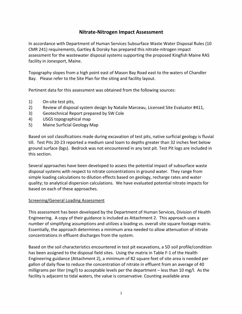
1
Nitrate-Nitrogen Impact Assessment In accordance with Department of Human Services Subsurface Waste Water Disposal Rules (10 CMR 241) requirements, Gartley & Dorsky has prepared this nitrate-nitrogen impact assessment for the wastewater disposal systems supporting the proposed Kingfish Maine RAS facility in Jonesport, Maine. Topography slopes from a high point east of Mason Bay Road east to the waters of Chandler Bay. Please refer to the Site Plan for the siting and facility layout. Pertinent data for this assessment was obtained from the following sources: 1) On-site test pits, 2) Review of disposal system design by Natalie Marceau, Licensed Site Evaluator #411, 3) Geotechnical Report prepared by SW Cole 4) USGS topographical map 5) Maine Surficial Geology Map Based on soil classifications made during excavation of test pits, native surficial geology is fluvial till. Test Pits 20-23 reported a medium sand loam to depths greater than 32 inches feet below ground surface (bgs). Bedrock was not encountered in any test pit. Test Pit logs are included in this section. Several approaches have been developed to assess the potential impact of subsurface waste disposal systems with respect to nitrate concentrations in ground water. They range from simple loading calculations to dilution effects based on geology, recharge rates and water quality; to analytical dispersion calculations. We have evaluated potential nitrate impacts for based on each of these approaches. Screening/General Loading Assessment This assessment has been developed by the Department of Human Services, Division of Health Engineering. A copy of their guidance is included as Attachment 2. This approach uses a number of simplifying assumptions and utilizes a loading vs. overall site square footage matrix. Essentially, the approach determines a minimum area needed to allow attenuation of nitrate concentrations in effluent discharges from the system. Based on the soil characteristics encountered in test pit excavations, a 5D soil profile/condition has been assigned to the disposal field sites. Using the matrix in Table F-1 of the Health Engineering guidance (Attachment 2), a minimum of 82 square feet of site area is needed per gallon of daily flow to reduce the concentration of nitrate in effluent from an average of 40 milligrams per liter (mg/l) to acceptable levels per the department – less than 10 mg/l. As the facility is adjacent to tidal waters, the value is conservative. Counting available area

2
Assuming that 4,385 gallons per day is the total design flow for the proposed disposal fields, a total site square footage of 353,570 sq. ft. or approximately 8.25 acres of land is required for nitrate attenuation. The actual site acreage 93.2 acres or approximately 11 times greater than the minimum. On this basis, the site is acceptable with respect to nitrate-nitrogen impacts. Mixing/Dilution Assessment A mixing/dilution calculation approach is described in Section 14.B.2.(d) of the Maine Department of Environmental Protection (DEP) Site Location Permit Application. This approach is used as an alternate method to evaluate nitrate-nitrogen impacts on development Sites that utilize on-site subsurface wastewater disposal systems. Kingfish Maine’s project is subject to Site Location Permit requirements. Because of sufficient undeveloped and buffer area on the majority of the property nitrate evaluations by mixing/dilution are appropriate for assessment. The following information was used in the calculation of mixing and dilution: • The project area is 93 acres in size and contain slopes on the order of 3 to 8%. • National Weather Service records indicate that average annual precipitation is
approximately 46 inches. A conservative drought condition (60%) of 27.6 inches was assessed.
• Site soils were classified as hydrologic soil group A. Based on this classification and Table d(ii) of the Site Location Application, a recharge rate of 43% of average annual precipitation has been selected for the Site, conservatively applied to the area outside the development area, or 2,758,526 sf. Owing to provisions of the Site Law and Stormwater Law, the development footprint is diverted to stormwater features that effectively manage stormwater but may inhibit recharge. Conservatively, these areas are excluded.
• A design flow of 4,000 gpd has been established for system 1 and 385 gpd for system 2. • Initial concentration of Nitrate-Nitrogen for effluent from the wastewater disposal system is
assumed to be 40 mg/l, which is typical of domestic wastewater. Background is estimated at 2.0 mg/l.
• Concentration of Nitrate-Nitrogen in precipitation is assumed to be 0.5 mg/l as recommended by DEP.
Cd = Qe Ce + Qr Cr Qe + Qr Where: Cd = the diluted nitrate concentration Qe = volume of effluent in liters per year (6,058,643 liters) Ce = nitrate concentration of effluent (40 mg/l) Qr = volume of recharge over 2,758,526 sf from precipitation in liters (142,750,830 liters) Cr = nitrate concentration in recharge (0.5 mg/l)
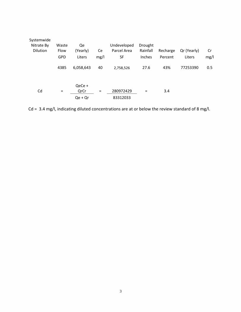
3
Systemwide Nitrate By Dilution
Waste Flow
Qe (Yearly) Ce
Undeveloped Parcel Area
Drought Rainfall Recharge Qr (Yearly) Cr
GPD Liters mg/l SF Inches Percent Liters mg/l
4385
6,058,643 40 2,758,526 27.6 43% 77253390 0.5
Cd = QeCe +
QrCr = 280972429 = 3.4 Qe + Qr 83312033
Cd = 3.4 mg/l, indicating diluted concentrations are at or below the review standard of 8 mg/l.