Embed Size (px)
Citation preview
The Environmental Protection Agency
CODE OF PRACTICEWastewater Treatment and Disposal Systems Serving Single Houses(p.e. ≤ 10)

The Environmental Protection Agency (EPA) is a statutory body responsible for protecting the environment in Ireland. We regulate and police activities that might otherwise cause pollution. We ensure there is solid information on environmental trends so that necessary actions are taken. Our priorities are protecting the Irish environment and ensuring that development is sustainable.
The EPA is an independent public body established in July 1993 under the Environmental Protection Agency Act, 1992. Its sponsor in Government is the Department of the Environment, Heritage and Local Government.
OUR RESPONSIBILITIES
LICENSING
We license the following to ensure that their emissions do not endanger human health or harm the environment:
• waste facilities (e.g., landfills, incinerators, waste transfer stations);
• large scale industrial activities (e.g., pharmaceutical manufacturing, cement manufacturing, power plants);
• intensive agriculture;
• the contained use and controlled release of Genetically Modified Organisms (GMOs);
• large petrol storage facilities;
• waste water discharges.
NATIONAL ENVIRONMENTAL ENFORCEMENT
• Conducting over 2,000 audits and inspections of EPA licensed facilities every year.
• Overseeing local authorities’ environmental protection responsibilities in the areas of - air, noise, waste, waste-water and water quality.
• Working with local authorities and the Gardaí to stamp out illegal waste activity by co-ordinating a national enforcement network, targeting offenders, conducting investigations and overseeing remediation.
• Prosecuting those who flout environmental law and damage the environment as a result of their actions.
MONITORING, ANALYSING AND REPORTING ON THE ENVIRONMENT
• Monitoring air quality and the quality of rivers, lakes, tidal waters and ground waters; measuring water levels and river flows.
• Independent reporting to inform decision making by national and local government.
REGULATING IRELAND’S GREENHOUSE GAS EMISSIONS
• Quantifying Ireland’s emissions of greenhouse gases in the context of our Kyoto commitments.
• Implementing the Emissions Trading Directive, involving over 100 companies who are major generators of carbon dioxide in Ireland.
ENVIRONMENTAL RESEARCH AND DEVELOPMENT
• Co-ordinating research on environmental issues (including air and water quality, climate change, biodiversity, environmental technologies).
STRATEGIC ENVIRONMENTAL ASSESSMENT
• Assessing the impact of plans and programmes on the Irish environment (such as waste management and development plans).
ENVIRONMENTAL PLANNING, EDUCATION AND GUIDANCE
• Providing guidance to the public and to industry on various environmental topics (including licence applications, waste prevention and environmental regulations).
• Generating greater environmental awareness (through environmental television programmes and primary and secondary schools’ resource packs).
PROACTIVE WASTE MANAGEMENT
• Promoting waste prevention and minimisation projects through the co-ordination of the National Waste Prevention Programme, including input into the implementation of Producer Responsibility Initiatives.
• Enforcing Regulations such as Waste Electrical and Electronic Equipment (WEEE) and Restriction of Hazardous Substances (RoHS) and substances that deplete the ozone layer.
• Developing a National Hazardous Waste Management Plan to prevent and manage hazardous waste.
MANAGEMENT AND STRUCTURE OF THE EPA
The organisation is managed by a full time Board, consisting of a Director General and four Directors.
The work of the EPA is carried out across four offices:
• Office of Climate, Licensing and Resource Use
• Office of Environmental Enforcement
• Office of Environmental Assessment
• Office of Communications and Corporate Services
The EPA is assisted by an Advisory Committee of twelve members who meet several times a year to discuss issues of concern and offer advice to the Board.
Environmental Protection Agency
46696 EPA code of practice cover3 3 22/06/2009 11:02:00

CODE OF PRACTICE
WASTEWATER TREATMENT AND DISPOSAL
SYSTEMS SERVING SINGLE HOUSES
(p.e. ≤ 10)
ENVIRONMENTAL PROTECTION AGENCY
An Ghníomhaireacht um Chaomhnú ComhshaoilPO Box 3000, Johnstown Castle, Co. Wexford, Ireland
Telephone: +353 53 916 0600 Fax: +353 53 916 0699E-mail: [email protected] Website: www.epa.ie

Environmental Protection Agency i
© Environmental Protection Agency 2009
DISCLAIMER
Although every effort has been made to ensure the accuracy of the material contained in thispublication, complete accuracy cannot be guaranteed. Neither the Environmental ProtectionAgency nor the author(s) accept any responsibility whatsoever for loss or damage occasioned orclaimed to have been occasioned, in part or in full, as a consequence of any person acting, orrefraining from acting, as a result of a matter contained in this publication. All or part of thispublication may be reproduced without further permission, provided the source is acknowledged.
CODE OF PRACTICE
WASTEWATER TREATMENT AND DISPOSAL SYSTEMS SERVING SINGLE HOUSES (p.e. ≤ 10)
Published by the Environmental Protection Agency, Ireland
ISBN: 978-1-84095-196-7 10/09/1500
Price: €20

ACKNOWLEDGEMENTS
The principal authors of this Code of Practice (CoP) are Ms Margaret Keegan, EPA, and Mr FrankClinton, EPA. Mr Laurence Gill, Trinity College Dublin (TCD), provided valuable technical input andreview during the drafting stages. Other personnel involved in the production and preparation of thecode were Mr John Mulqueen, National University of Ireland Galway (NUIG), Dr Michael Rodgers,NUIG, Dr Cormac O’Suilleabhain, TCD, Mr Niall O’Luanaigh, TCD, Mr Gerard O’Leary, EPA, and MrDermot Burke, EPA. The CoP builds on the EPA 2000 Guidance Manual (Mr John Mulqueen, DrMichael Rodgers, Mr Gerard O’Leary and Mr Gerry Carty), which provided a new approach to on-site wastewater treatment assessment in Ireland.
In order to examine the position in relation to on-site systems (in Ireland and internationally) and toproduce draft guidelines for their future use, a research project in relation to on-site systems waspart-financed by the European Union through the European Regional Development Fund as part ofthe Environmental Monitoring, R&D sub-programme of the Operational Programme forEnvironmental Services, 1994–1999. The sub-programme was administered on behalf of theDepartment of the Environment and Local Government by the Environmental Protection Agency,which has the statutory function of co-ordinating and promoting environmental research. The studySmall Scale Wastewater Treatment Systems was co-ordinated by the Department of CivilEngineering, NUIG, from 1995 to 1997.
In late 2000, as part of the Environmental Research, Technological Development and Innovation(ERTDI) programme 2000–2006, the EPA approved a further research project to be undertaken bythe Department of Civil, Structural and Environmental Engineering at TCD. The Irish Governmentunder the National Development Plan 2000–2006 financed the ERTDI programme. This laterproject was entitled Establishment of the Hydraulic Performance and Efficiencies of DifferentSubsoils and the Effectiveness of Stratified Sand Filters (2000-MS-15-M1). This project was laterextended to examine the efficiencies of subsoils for on-site wastewater treatment and disposal withrespect to endocrine disrupting chemicals. A further research project by TCD on The EffectiveDistribution of On-Site Wastewater Effluent into Percolation Areas via Distribution Boxes andTreatment by Reed Beds Compared to Attenuation of Pollutants in Sandy Subsoils (2005–MS-15)has recently been completed.
The NUIG and TCD researchers are internationally recognised for their work on wastewatertreatment systems and have published in peer-reviewed international journals and presented theirfindings at international conferences. The findings of the research were used to inform therequirements of the CoP.
The Agency also wishes to acknowledge the contribution of the various sections of the Departmentof the Environment, Heritage and Local Government (DoEHLG), National Standards Authority ofIreland (NSAI), Irish Agrément Board (IAB), An Bord Pleanála, Domestic Effluent Trade Association(DETA), Geological Survey of Ireland (GSI), the County and City Managers Association, LocalAuthority personnel, River Basin District Project co-ordinators, Fisheries Boards, Irish On-SiteWastewater Association (IOWA) as well as the tutors and participants of the FÁS SiteCharacterisation courses and comments by practitioners in the field and the numerous individualcontributors during the consultation period 20th July to 10th September 2007.
Finally, the authors would also like to acknowledge the assistance of EPA colleagues Dr MatthewCrowe, Mr Donal Daly, Mr Brendan Wall and Mr Leo Sweeney.
Yellowstone Communications Design produced the graphics and its input is acknowledged.
Environmental Protection Agency ii
Abbreviations
Agency Environmental Protection Agency
BAF Biological aerated filters
BOD5 Biochemical oxygen demand (5 day)
BS British Standard
C Capacity
°C Degrees Celsius
CEN Comité Européen de Normalisation (European Committee for Standardisation)
CEN/TR Technical report prepared by CEN
CEN/TS Technical specification prepared by CEN
COD Chemical oxygen demand
CoP Code of Practice
Cu Uniformity co-efficient
DoEHLG Department of the Environment, Heritage and Local Government
DO Dissolved oxygen
DWF Dry weather flow
EN European Standard (note, prEN indicates draft standard)
EPA Environmental Protection Agency
FETAC Further Education and Training Awards Council
FOG Fats, oils and grease
FWS Free-water surface
g Gram
GSI Geological Survey of Ireland
GWPR Groundwater protection response
GWPS Groundwater protection scheme
h Hour
K Hydraulic conductivity
kg Kilogram
I.S. Irish Standard
ISO International Organisation for Standardisation
l Litre
lcd Litres per capita per day
m Metre
m3 Cubic metres
mg Milligram
mm Millimetre
MPN Most probable number
m/s Metres per second
NHA National Heritage Area
NSAI National Standards Authority of Ireland
NUI National University of Ireland
p.e. Population equivalent
PFP Preferential flow path
PSD Particle size distribution
Environmental Protection Agency iii

PT Population total (Population equivalent)
RBC Rotating biological contactors
s Second
SAC Special Area of Conservation
SBR Sequencing batch reactor
SFS Subsurface flow system
S.I. Statutory Instrument
SPA Special Protection Area
SS Suspended solids
T/P The T-value (expressed as min/25 mm) is the time taken for the water level to drop a specified distance in a percolation test hole. For shallow subsoils the test hole requirements are different and hence the test results are called P-values. For further advice see Annex C.
TSS Total suspended solids
TWL Top water level
WT Water table
Environmental Protection Agency iv


Preface
The Agency is authorised under Section 76 ofthe Environmental Protection Agency (EPA)Act, 1992 (as amended), to prepare andpublish codes of practice for the purpose ofproviding guidance with respect to compliancewith any enactment or otherwise, for thepurposes of environmental protection. ThisCode of Practice (CoP) replaces previousguidance issued by the Agency in 2000 andincorporates requirements of the newEuropean standards from the 12566 series,EPA research findings and feedback onprevious EPA guidance and research reports.The document is published as a CoP underSection 76 of the Environmental ProtectionAgency Act, 1992 (as amended), and shall bereceived in evidence without further proof.
This CoP will replace the guidance documentStandard Recommendation I.S. SR 6:1991issued by the National Standards Authority ofIreland when the Department of theEnvironment, Heritage and Local Governmentincorporates the CoP in the BuildingRegulations.
When on-site systems fail to operatesatisfactorily they threaten public health andwater quality. When domestic wastewater isnot absorbed by the soil it can form stagnantpools on the ground surface. In such failures,humans can come in contact with thewastewater and be exposed to pathogens; alsofoul odours can be generated. In addition,inadequately treated wastewater through poorsiting, design and/or construction may lead tocontamination of our groundwaters and surfacewaters, which in many areas are also used asdrinking water supplies. It is essential that thiseffluent is properly treated and disposed of.
The key messages of the CoP are:
• The importance of proper site assessment,taking account of not only local conditionsspecific to the proposed site but also ofwider experience in the area, patterns of
development, provisions of thedevelopment plan and other policies, etc.
• The need for design of on-site wastewaterdisposal systems specific to the localconditions
• The need for follow-through by thebuilder/homeowner/supervisory authority –i.e. installation/commissioning/maintenanceas per design and attendantrecommendations/conditions – otherwisebreaches of various legislative codes areoccurring.
The purpose of this CoP is to provide guidanceon the provision of wastewater treatment anddisposal systems for new single houses with apopulation equivalent (p.e.) of less than orequal to 10 and contains the following:
• An assessment methodology to determinesite suitability for on-site wastewatertreatment systems and to identify minimumenvironmental protection requirements
• A methodology to select suitablewastewater treatment systems for sites inun-sewered rural areas
• Information on the design and installation ofseptic tank systems, filter systems andpackaged treatment systems
• Information on tertiary treatment systems,and
• Maintenance requirements.
This CoP has been prepared having regard tocurrent standards and guidelines and will assistplanning authorities, builders, systemmanufacturers, system designers, systeminstallers and system operators to deal with thecomplexities of on-site systems for singlehouses.
Site suitability assessors should carry out allassessments in accordance with the guidanceprovided in this CoP. The site suitability
Environmental Protection Agency vi

Code of Practice: Wastewater Treatment and Disposal Systems Serving Single Houses (p.e. ≤ 10)
assessment methodology set out in thisdocument should be used by planningauthorities to satisfy the requirements ofArticle 22 (c) of the Planning and DevelopmentRegulations, 2006. There is also an obligationon the proposed house builder/owner to ensurethat any planning application submitted shouldinclude an assessment of the site andrecommendations in accordance with theguidance provided in this CoP. In addition, it isessential that the wastewater treatment systeminstalled on site complies with the conditions ofplanning and that the system is properlyinstalled and maintained in accordance with theguidance in Sections 11 and 12.
The CoP is divided into two parts: Part Onesets out requirements for on-site wastewater
systems used to treat and dispose of domesticwastewater from single houses. Guidance ongood practice is included in Part Two andinforms the implementation of the requirementsof Part One.
The figures and diagrams in this CoP are forillustration purposes to assist the users of thiscode. They should not be considered assubstitutes for detailed design drawings.
The code will be subject to ongoing review. TheAgency welcomes any suggestions, that usersof the CoP wish to make. These should bereturned to the Office of EnvironmentalEnforcement at the Environmental ProtectionAgency Regional Inspectorate, McCumiskeyHouse, Richview, Clonskeagh Rd, Dublin 14.
Environmental Protection Agency vii

Table of Contents
Disclaimer i
Acknowledgements ii
Abbreviations iii
Preface vi
List of Figures xi
List of Tables xiii
PART ONE: CODE OF PRACTICE 1
1 Scope 1
2 References 2
3 Definitions 3
4 Wastewater Characteristics 6
5 On-Site Wastewater Treatment System Performance 7
5.1 Performance Standards 8
6 Site Characterisation 10
6.1 Desk Study 11
6.2 On-Site Assessment 13
6.3 Discharge Route 16
6.4 Selecting an Appropriate On-Site Domestic Wastewater Treatment and Disposal System 17
6.5 Site Improvement Works 17
6.6 Recommendations 18
7 Septic Tank Systems 19
7.1 Septic Tanks 19
7.2 Percolation Areas 21
8 Secondary Treatment: Systems Constructed On-Site 25
8.1 Soil Filter Systems 27
8.2 Sand Filter Systems 29
8.3 Drainage and Sealing of Filter Systems 31
Environmental Protection Agency viii

8.4 Mounded Intermittent Filter Systems 31
8.5 Application of Wastewater to Filter Systems 33
8.6 Constructed Wetlands 33
9 Secondary Treatment: Packaged Wastewater Systems 37
9.1 Location of Packaged Wastewater Systems 38
9.2 Biological Aerated Filter (BAF) Systems 38
9.3 Rotating Biological Contactor (RBC) Systems 38
9.4 Sequencing Batch Reactor System (SBR) 39
9.5 Membrane Filtration Systems 40
9.6 Media Filter Systems 40
9.7 Other Treatment Systems 41
10 Tertiary Treatment Systems 43
10.1 Polishing Filters 43
10.2 Constructed Wetlands 45
10.3 Packaged Tertiary Treatment Systems 45
11 Construction and Installation Issues 46
11.1 Septic Tanks and Pipework 46
11.2 Secondary Treatment: Package Wastewater Systems 47
11.3 Infiltration Systems 47
11.4 Installation 48
12 Operation and Maintenance of Wastewater Treatment Systems 51
12.1 Introduction 51
12.2 Record Keeping 52
PART TWO: GUIDANCE 53
Annex A Policy Background 53
Annex B Groundwater Protection Response 57
Annex C Site Characterisation 63
Annex D Discharge Options 89
Annex E Wastewater Treatment and Disposal Systems 91
Environmental Protection Agency ix

Annex F Site Improvement Works 96
Annex G Operation and Maintenance 97
Annex H References and Reading Material 102
Environmental Protection Agency x

9
List of Figures
Figure 5.1 Methods of wastewater treatment in line with EN 12566 7
Figure 6.1 Schematic of source–pathway–target model 10
Figure 6.2 A general guide to the selection of an on-site wastewater treatment system discharging to ground 12
Figure 7.1 Plan and section of layout of septic tank system 20
Figure 7.2 Longitudinal section of a typical septic tank (all dimensions in mm) 21
Figure 7.3 Section of a percolation trench 22
Figure 7.4 Raised percolation area 23
Figure 8.1 Illustration of a pumped distribution system 26
Figure 8.2 Illustration of intermittent filter system or constructed wetland system 27
Figure 8.3 Schematic diagram of an intermittent soil filter 27
Figure 8.4 Intermittent sand filter system with underlying sand/subsoil polishing filter 29
Figure 8.5 Schematic cross section of stratified sand filter 31
Figure 8.6 Intermittent sand filter overlying impervious subsoil/bedrock with offset polishing filter 32
Figure 8.7 Intermittent soil filter (above ground) 32
Figure 8.8 Horizontal subsurface flow reed bed 34
Figure 8.9 Vertical subsurface flow reed bed 35
Figure 9.1 Schematic of a biological aerated filter system (BAF) 38
Figure 9.2 Schematic of a rotating biological contactor (RBC) system 39
Figure 9.3 Schematic of a sequencing batch reactor (SBR) system 3
Figure 9.4 Schematic layout of a membrane filtration system 40
Figure 9.5 Schematic of a packaged peat filter system 41
Figure 9.6 Illustration of a package system and polishing filter system 42
Figure 11.1 Infiltration trenches – layout examples 49
Figure B.1 Relative location of wells 61
Environmental Protection Agency xi

Figure C.1 Indicator plants of dry and wet conditions 66
Figure C.2 Close-up of mottling in trial hole 67
Figure C.3 Idealised cross section of the T-test holes and the proposed percolation trench 73
Figure C.4 Cross section of the P-test holes and the proposed percolation trench 75
Figure E.1 Illustration of biomat formation on the base of a percolation trench 92
Environmental Protection Agency xii

Environmental Protection Agency xiii
List of Tables
Table 4.1 Range of raw domestic wastewater influent characteristics (I.S. EN 12566-3:2005) 6
Table 5.1 On-site domestic wastewater treatment minimum performance standards 9
Table 6.1 Minimum separation distances in metres 14
Table 6.2 Depth requirements on-site for on-site systems discharging to ground 14
Table 6.3 Interpretation of percolation test results 16
Table 7.1 Nominal septic tank capacity for various design populations 21
Table 7.2 Percolation trench length 21
Table 7.3 Requirements of a percolation trench (gravity fed) 23
Table 8.1 Soil filter requirements 28
Table 8.2 Sand filter requirements 30
Table 8.3 Criteria for constructed wetland systems receiving septic tank effluent 35
Table 10.1 Minimum soil polishing filter areas and percolation trench lengths requiredfor a five-person house 44
Table 10.2 Criteria for sand-polishing filter 45
Table 10.3 Criteria for tertiary treatment 45
Table 11.1 Gradients for drain to septic tank 47
Table 12.1 Installation, inspection and monitoring schedule 52
Table B.1 Characteristics of domestic wastewater for a single house 58
Table B.2 Response matrix for on-site treatment systems 59
Table B.3 Recommended minimum distance between a receptor and a percolation area or polishing filter 62
Table C.1 Factors to be considered during visual assessment 64
Table C.2 Factors to be considered during a trial hole examination 67
Table C.3 Subsoil classification against T-values for 400 T-tests (Jackson, 2005) 68
Table C.4 Step 3 of percolation test (T-test) procedure 73
Table C.5 Standard Method 74

Table C.6 Modified Method 75
Table C.7 Information obtained from desk study and on-site assessment 76
Table E.1 Attributes of a typical septic tank 93
Table E.2 Factors used to compare different wastewater treatment systems 94
Environmental Protection Agency xiv


PART ONE: CODE OF PRACTICE1 Scope
This Code of Practice (CoP) is published underSection 76 of the Environmental ProtectionAgency Act, 1992 (as amended). Part One setsout requirements for new on-site wastewatersystems used to treat and dispose of domesticwastewater from single houses with apopulation equivalent (p.e.) less than or equalto 10. It sets out a methodology that should befollowed to allow site conditions to beassessed, and an appropriate wastewatertreatment system to be selected, installed andmaintained, and it should be implemented infull. Guidance on good practice is included inPart Two; it should be considered as generalguidance as site conditions determineparticular site requirements. The guidanceinforms the implementation of the requirementsof Part One. The code’s requirements shouldbe supplemented as required by technicalskilled advice based on knowledge of sewageworks practice and local conditions.
Annex A provides the policy and legislationbackground to the development of this CoP.
This code replaces previous guidance issuedby the Agency in 2000 and incorporates the
requirements of the Comité Européen deNormalisation (European Committee forStandardisation) (CEN) European standardsprepared by CEN TC 165 and called the EN12566 series of standards: Small WastewaterTreatment Systems for up to 50 PT, researchfindings and feedback on previous guidancedocuments. Following the guidance containedwithin the code does not remove yourobligation to comply with relevant legislationand to prevent pollution from your site.
Innovative products and technologies, notspecifically covered by national or Europeanharmonised standards, should be certified(certification may include a EuropeanTechnical Approval, an Agrément Certificate orequivalent), be fit for the purpose for which theyare intended, the conditions in which they areused, and meet the performance requirementsof this CoP.
Where reference in the document is made toproprietary equipment, this is intended toindicate equipment type and is not to beinterpreted as endorsing or excluding anyparticular manufacturer or system.
This CoP also provides guidance to localauthorities where an existing system isproposed to be upgraded. For dwellings withgreater than 10 people (i.e. guest houses orcluster developments), the reader is referred toBS 6297:2007+A1:2008 Code of practice forthe design and installation of drainage fields foruse in wastewater treatment and EN 12255series Wastewater Treatment Plants, theEnvironmental Protection Agency (EPA)manual Wastewater Treatment Systems forSmall Communities, Leisure Centres andHotels (1999) and any further guidancedeveloped by the EPA including guidance inrelation to Section 4 discharges to surfacewaters or groundwater.
To protect the environment and, in particular,water quality, houses in un-sewered areas mustbe on suitable sites and must have anappropriate wastewater treatment system thatis correctly installed and maintained.Homeowners and builders who propose to buildhouses in un-sewered areas are required toundergo site assessments to ensure that thesite is suitable for an off-mains system. Theyare responsible for their wastewater treatmentsystems and should follow all planningrequirements and guidance provided in thiscode of practice. The primary responsibility forprotecting waters against pollution rests withany person who is carrying on an activity thatpresents a threat to water quality.
Environmental Protection Agency 1
Code of Practice: Wastewater Treatment and Disposal Systems Serving Single Houses (p.e. ≤ 10)
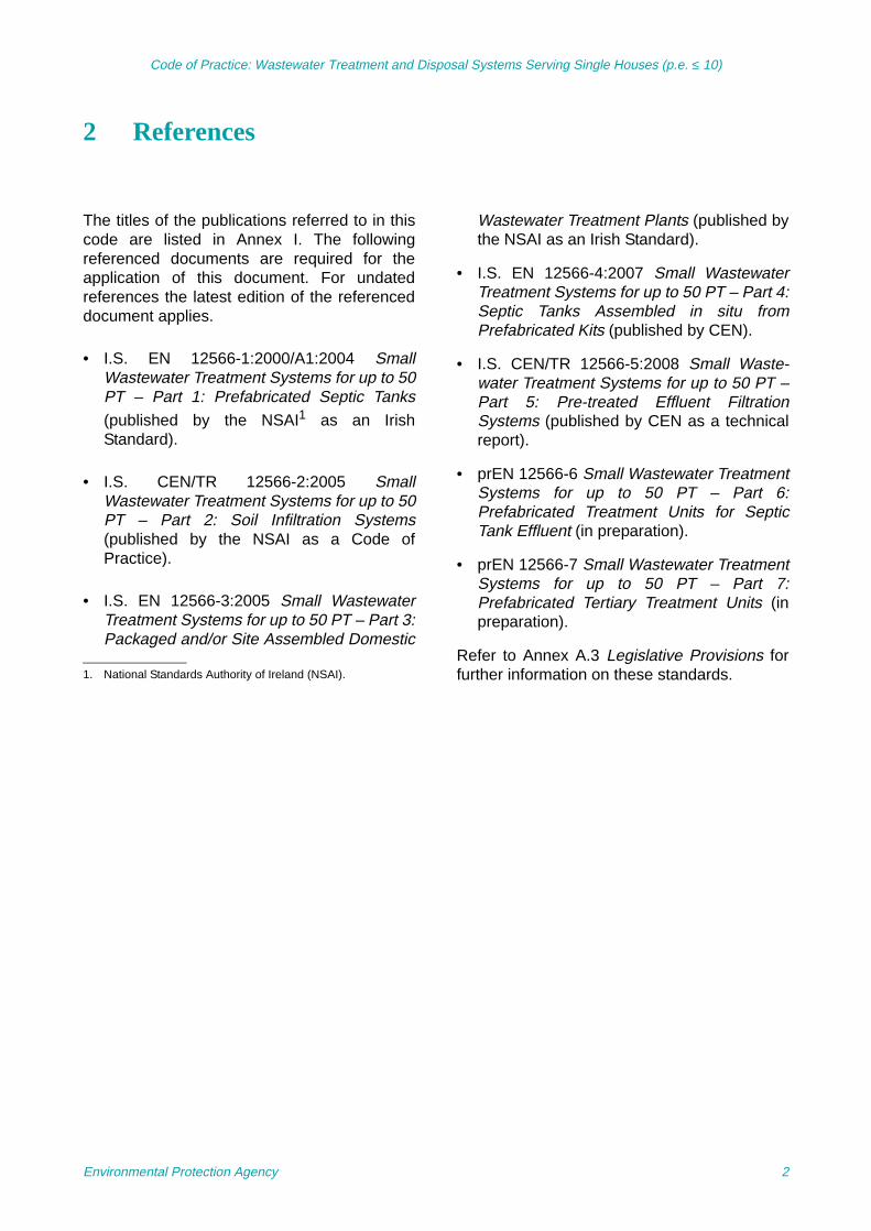
2 References
The titles of the publications referred to in thiscode are listed in Annex I. The followingreferenced documents are required for theapplication of this document. For undatedreferences the latest edition of the referenceddocument applies.
• I.S. EN 12566-1:2000/A1:2004 SmallWastewater Treatment Systems for up to 50PT – Part 1: Prefabricated Septic Tanks(published by the NSAI1 as an IrishStandard).
• I.S. CEN/TR 12566-2:2005 SmallWastewater Treatment Systems for up to 50PT – Part 2: Soil Infiltration Systems(published by the NSAI as a Code ofPractice).
• I.S. EN 12566-3:2005 Small WastewaterTreatment Systems for up to 50 PT – Part 3:Packaged and/or Site Assembled Domestic
Wastewater Treatment Plants (published bythe NSAI as an Irish Standard).
• I.S. EN 12566-4:2007 Small WastewaterTreatment Systems for up to 50 PT – Part 4:Septic Tanks Assembled in situ fromPrefabricated Kits (published by CEN).
• I.S. CEN/TR 12566-5:2008 Small Waste-water Treatment Systems for up to 50 PT –Part 5: Pre-treated Effluent FiltrationSystems (published by CEN as a technicalreport).
• prEN 12566-6 Small Wastewater TreatmentSystems for up to 50 PT – Part 6:Prefabricated Treatment Units for SepticTank Effluent (in preparation).
• prEN 12566-7 Small Wastewater TreatmentSystems for up to 50 PT – Part 7:Prefabricated Tertiary Treatment Units (inpreparation).
Refer to Annex A.3 Legislative Provisions forfurther information on these standards.1. National Standards Authority of Ireland (NSAI).
Environmental Protection Agency 2
Code of Practice: Wastewater Treatment and Disposal Systems Serving Single Houses (p.e. ≤ 10)
3 Definitions
Activated sludge treatment: Activated sludge is a process in sewage treatment in which air or oxygen is forced intosewage liquor to develop a biological floc, which reduces the organic content of thesewage.
Aquifer: Any stratum or combination of strata that stores or transmits groundwater.
Bedrock: The solid rock beneath the soil and superficial rock. A general term for solid rock that liesbeneath soil, loose sediments, or other unconsolidated material (subsoil).
Biochemical oxygen demand (BOD): BOD is a measure of the rate at which micro-organisms use dissolved oxygen in thebiochemical breakdown of organic matter in wastewaters under aerobic conditions. TheBOD5 test indicates the organic strength of a wastewater and is determined by measuringthe dissolved oxygen concentration before and after the incubation of a sample at 20°C for5 days in the dark. An inhibitor may be added to prevent nitrification from occurring.
Biofilm: A thin layer of micro-organisms and organic polymers attached to a medium such as soil,sand, peat, and inert plastic material.
Biological aerated filter (BAF): A treatment system normally consisting of a primary settlement tank, an aerated biofilmand, possibly, a secondary settlement tank. The system is similar to the percolating filtersystem except that the media are commonly submerged (termed SAF) and forced air isapplied.
Biomat: A biologically active layer that covers the bottom and sides of percolation trenches andpenetrates a short distance into the percolation soil. It includes complex bacterialpolysaccharides and accumulated organic substances as well as micro-organisms.
Chemical oxygen demand (COD): COD is a measure of the amount of oxygen consumed from a chemical oxidising agentunder controlled conditions. The COD is greater than the BOD as the chemical oxidisingagent will often oxidise more compounds than micro-organisms.
Collection chamber: A chamber receiving treated wastewater from the collection layer and discharging throughthe pipe to an outfall or polishing filter/tertiary treatment system.
Collection pipe: A perforated pipe placed at the bottom of a trench, within the collection layer connected tothe collection chamber.
Competent person: A person with the necessary training, skills and practical experience to enable the requiredwork (i.e. site characterisation or system installation or maintenance) to be carried out.
Constructed wetlands (CW): A wetland system supporting vegetation, which provides secondary treatment by physicaland biological means to effluent from a primary treatment step. Constructed wetlands mayalso be used for tertiary treatment.
Cu: The uniformity co-efficient is a measure of the particle size range. Cu < 5 – very uniform;Cu = 5 – medium uniform; Cu > 5 – non-uniform.
Distribution box/device: A chamber between the septic tank and the percolation area, arranged to distribute the tankwastewater in approximately equal quantities through all the percolation pipes leading fromit.
Distribution layer: A layer of the system composed of granular fill material in which pretreated effluent from theseptic tank is discharged through infiltration pipes.
Distribution pipe: A non-perforated pipe used to connect the distribution box to an infiltration pipe.
Extended aeration: An activated sludge process where a long aeration phase enables reduction of organicmaterial in the sludge.
Geotextile: Man-made fabric, which is permeable to liquid and air but prevents solid particles frompassing through it and is resistant to decomposition.
Groundwater protection response: Control measures, conditions or precautions recommended as a response to theacceptability of an activity within a groundwater protection zone as set out in theGSI/EPA/DoELG document Groundwater Protection Responses for On-Site Systems forSingle Houses.
Environmental Protection Agency 3

Code of Practice: Wastewater Treatment and Disposal Systems Serving Single Houses (p.e. ≤ 10)
Groundwater protection scheme (GWPS):
A scheme comprising two main components: a land surface zoning map whichencompasses the hydrogeological elements of risk and a groundwater protection responsefor different activities.
Hydraulic conductivity: The volume of water will move in a porous medium in unit time under a unit hydraulicgradient through a unit area measured at right angles to the direction of flow. In contrast topermeability, it is a function of the properties of the liquid as well as of the porous medium.
Infiltration system: Comprises percolation areas and polishing filters that discharge partially treated and treatedeffluent into the ground.
Mottling: The occurrence of reddish/brown spots or streaks in a matrix of dark grey soil; thereddish/brown spots or streaks are due to intermittent aeration and the grey colours may bedue to anaerobic conditions.
Nutrient-sensitive locations: These are locations, which include rivers designated as nutrient sensitive under the UrbanWaste Water Treatment Regulations and groundwater bodies, where a programme ofmeasures are needed to achieve the objectives of the Water Framework Directive.
Organic matter: Mainly composed of proteins, carbohydrates and fats. Most of the organic matter indomestic wastewater is biodegradable. A measure of the biodegradable organic matter canbe obtained using the BOD test.
Ortho-phosphorus: Ortho-phosphorus is soluble reactive phosphorus and is readily available for biologicaluptake.
Pathogenic organisms: Those potential disease-producing micro-organisms which can be found in domesticwastewaters. Organisms, such as Escherichia coli, and faecal streptococci, with the sameenteric origin as the pathogens are used to indicate whether pathogens may be present ornot in the wastewater.
Peat filter: A filter system consisting of peat used to treat wastewater from a primary settlement tank(usually a septic tank) by biological and physical means.
Perched water table: Unconfined groundwater separated from an underlying body of groundwater by animpervious or perching layer.
Percolating filter system: A wastewater treatment system consisting of primary settlement and biological treatment(effected by distributing the settled liquid onto a suitable inert medium to which a biofilmattaches) followed by secondary settlement.
Percolation area: A system consisting of trenches with pipes and gravel aggregates, installed for the purposeof receiving wastewater from a septic tank or other treatment device and transmitting it intosoil for final treatment and disposal. This system is also called a soil infiltration system(EN 12566), drain field, seepage field or bed, distribution field, subsurface disposal area, orthe treatment and disposal field.
Percolation pipe: A perforated pipe through which the pretreated effluent from the septic tank is discharged tothe filtration trench or bed.
Polishing filter: A polishing filter is a type of infiltration system and can reduce micro-organisms andphosphorus (depending on soil type) in otherwise high quality wastewater effluents.
Population equivalent (p.e.): Population equivalent, conversion value which aims at evaluating non-domestic pollution inreference to domestic pollution fixed by EEC directive (Council Directive 91/271/EECconcerning Urban Waste Water Treatment) at 60 g/day related to BOD5.
Population total (PT): Sum of population and population equivalent (p.e.).
Preferential flow: A generic term used to describe the process whereby water movement follows favouredroutes through a porous medium bypassing other parts of the medium. Examples include,pores formed by soil fauna, plant root channels, weathering cracks, fissures and/orfractures.
Pretreated effluent: Wastewater that has undergone at least primary treatment.
Primary treatment: The primary treatment stage of treatment removes material that will either float or readilysettle out by gravity. It includes the physical processes of screening, comminution, gritremoval and sedimentation.
Environmental Protection Agency 4

Code of Practice: Wastewater Treatment and Disposal Systems Serving Single Houses (p.e. ≤ 10)
Raised percolation area: This is a term used to describe a percolation area where the percolation pipes are laid at adepth between 800 mm below ground surface and the ground surface itself. The in situ soiland subsoil are used to treat the effluent and material is brought in to provide protection forthe pipework.
Reed bed: An open filter system planted with macrophytes (reeds).
Rotating biological contactor (RBC): A contactor consisting of inert media modules mounted in the form of a cylinder on ahorizontal rotating shaft. Biological wastewater treatment is effected by biofilms that attachto the modules. The biological contactor is normally preceded by primary settlement andfollowed by secondary settlement.
Sand filter: A filter system consisting of sand used to treat wastewater from a primary settlement tank(usually a septic tank) by biological and physical means.
Secondary treatment: The secondary treatment stage of treatment by biological processes, such as activatedsludge or other (even non-biological) processes giving equivalent results.
Septic tank system: A wastewater treatment system that includes a septic tank mainly for primary treatment,followed by a percolation system in the soil providing secondary and tertiary treatment.
Sludge: The solids that settle in the bottom of the primary/secondary settlement tank.
Soil structure: The combination or arrangement of individual soil particles into definable aggregates, orpeds, which are characterised and classified on the basis of size, shape, and degree ofdistinctiveness.
Soil texture: The relative proportion of various soil components, including sands, silts, and clays, thatmake up the soil layers at a site.
Soil (topsoil): The upper layer of soil in which plants grow.
Submerged aerated filter (SAF) See biological aerated filter (BAF).
Subsoil: The soil material beneath the topsoil and above bedrock.
Suspended solids (SS): Includes all suspended matter, both organic and inorganic. Along with the BODconcentration, SS is commonly used to quantify the quality of a wastewater.
Swallow hole: A depression in the ground communicating with a subterranean passage (normally in karstlimestone) formed by solution or by collapse of a cavern roof.
Tertiary treatment: Tertiary treatment (advanced treatment) additional treatment processes which result infurther purification than that obtained by applying primary and secondary treatment.
Total nitrogen: Mass concentration of the sum of Kjeldahl (organic and ammonium nitrogen), nitrate andnitrite nitrogen.
Total phosphorus: Mass concentration of the sum of organic and inorganic phosphorus.
Trench: Also referred to as a percolation trench, means a ditch into which a single percolation pipeis laid, underlain and surrounded by gravel. The top layer of gravel is covered by soil.
Unsaturated soil: A soil in which some pores are not filled with water; these contain air.
Wastewater: The discharge from sanitary appliances, e.g. toilets, bathroom fittings, kitchen sinks,washing machines, dishwashers, showers, etc.
Water table: The position of the surface of the groundwater in a trial hole or other test hole.
Environmental Protection Agency 5

Code of Practice: Wastewater Treatment and Disposal Systems Serving Single Houses (p.e. ≤ 10)
4 Wastewater Characteristics
For the purposes of this CoP, a single-housesystem refers to a system serving a dwellinghouse of up to 10 people with toilet, living,sleeping, bathing, cooking and eating facilities.
The strength of the inflow in terms ofbiochemical oxygen demand (BOD) into an on-site system will largely depend on the waterusage in the house; for example, houses withdishwashers may have a wastewater BODstrength reduced by up to 35% due to dilutioneven though the total BOD load to thetreatment system (kg/day) remains the same.Household garbage grinders/sink maceratorscan increase the BOD loading rate by up to30% and their use is not recommended fordwellings, as they result in additionalmaintenance requirements due to increasedsolids, increase in electricity usage and do notencourage recycling, i.e. composting of organicwastes (Carey et al., 2008). The treatmentsystems covered by this CoP are notappropriate for the disposal of excessivequantities of waste oil and fats. These wastematerials should be collected and disposed ofby another appropriate method.
Under no circumstances should rainwater,surface water or run-off from paved areas bedischarged to on-site single-house treatmentsystems. However, grey waters (washingmachine, baths, showers, etc.) must pass tothe treatment system. To control the quantity ofwastewater generated in a household, waterconservation measures should be adopted.
Table 4.1 gives the range of influentcharacteristics for raw domestic wastewaterfrom I.S. EN 12566-3:2005. The CEN standardrequires that wastewater treatment systemsmust be tested using influents in this range.Research in Ireland indicates that Irishdomestic wastewater is at the moreconcentrated level of the characterised influentin I.S. EN 12566-3:2005, which in turnproduces a typically concentrated effluent (seeTable B.1 in Annex B).
The total design wastewater load should beestablished from the maximum population thatcan inhabit the premises, based on number andsize of bedrooms. In order to calculatewastewater capacities, a typical daily hydraulicloading of 150 l/person should be used toensure that adequate treatment is provided.
TABLE 4.1. RANGE OF RAW DOMESTIC WASTEWATER INFLUENT
CHARACTERISTICS (I.S. EN 12566-3:2005).
Parameter Typical concentration(mg/l unless otherwise stated)
Chemical oxygen demand (COD) (as O2) 300–1000
Biochemical oxygen demand (BOD5) (as O2) 150–500
Suspended solids 200–700
Ammonia (as NH4-N) 22–80
Total phosphorus (as P) 5–20
Total coliforms (MPN/100 ml)1 106–109
1Not from I.S. EN 12566-3:2005. (MPN, most probable number.)
Environmental Protection Agency 6

Code of Practice: Wastewater Treatment and Disposal Systems Serving Single Houses (p.e. ≤ 10)
5 On-Site Wastewater Treatment System Performance
The EN 12566 series of standards consists of anumber of parts – refer to Fig. 5.1 for theirapplications. The normative requirements ofthe standards, at the date of publication, havebeen incorporated into this CoP.
A treatment system should meet therequirements of I.S. EN 12566-3:2005 and befollowed by a disposal system designed to
prEN 12566-7 or as per the guidance providedwithin this code. Alternatively a treatmentsystem should consist of a product meeting therequirements of I.S. EN 12566-1:2000/A1:2004or I.S. EN 12566-4:2007 followed by a disposalsystem meeting the requirements of I.S.CEN/TR 12566-2:2005 or I.S. CEN/TR 12566-5:2008 or followed by a product meeting therequirements of prEN 12566-6 or as per the
FIGURE 5.1. METHODS OF WASTEWATER TREATMENT IN LINE WITH EN 12566.
Environmental Protection Agency 7

Code of Practice: Wastewater Treatment and Disposal Systems Serving Single Houses (p.e. ≤ 10)
guidance provided within this code. A tertiarytreatment system meeting the requirements ofprEN 12566-7 might be added to the totalsystem where higher levels of treatment arerequired by the local authority.
The performance of septic tank systems intreating domestic effluent relies primarily on thesoil attenuation capability of the percolationarea. Contaminant attenuation begins in theseptic tank and continues through thedistribution pipework, the surface of the biomat,the unsaturated soils and in the saturated zone.Research in the US indicates that filtration,microstraining, and aerobic biologicaldecomposition processes in the biomat andinfiltration zone remove more than 90% of BODand suspended solids (SS) and 99% of thebacteria (University of Wisconsin-Madison,1978) and similar results were found by theColorado School of Mines (Van Cuyk et al.,2005). These findings are supported by IrishEPA funded research projects (2001-MS 15-M1 and 2005-W-MS 15) undertaken by TCD.These septic tank systems are designed on aprescriptive basis (see Section 7), and areconsidered to achieve a satisfactory effluentquality, and treatment efficiency is usually notstated.
In general, wastewater treatment systems donot provide for the removal of significantamounts of nitrogen or phosphorus.
While septic tank systems can remove a limitedamount of nitrogen but high-density installationof wastewater treatment systems can causecontamination (Wakida and Lerner, 2005).
The Colorado School of Mines, Golden,Colorado (Van Cuyk et al., 2005) observed highremovals of phosphorus within soil infiltrationsystems throughout their study. As the finitesorption capacity of the upper layers of soilbecomes exhausted, soils at greater depths willbecome increasingly more important forphosphorus attenuation as operational timeextends for several years. Irish research by Gillet al. (2009a) also supports these findings.
For package wastewater treatment plants,compliance with phosphorus limits is usuallyachieved by dosing chemical coagulants intoinfluent to precipitate phosphates, which settle
out in the downstream settlement tank.Research shows that plants are capable ofremoving more than 90% of the totalphosphorus load with adequate coagulantdosing and chemical precipitation (Hellströmand Jonsson, 2003).
The absorption capacity of gravel media of reedbeds becomes exhausted after an extendedperiod (e.g. 6 months to 1 year). Solublephosphorus can pass forward with the treatedeffluent flow unless special media with a highabsorption capacity are used (Molle et al.,2003; Zhu et al., 2003; Gill et al., 2009b) and itis replaced regularly (e.g. every 5 years).
As phosphorus removal is dependent on thenatural mineralogy of the soil into which theeffluent is being discharged (both percolationarea and polishing filter) and there is a finitecapacity in the soil, this should not alone berelied upon in nutrient-sensitive areas.Secondary treatment systems may be modifiedto specifically improve their nutrient removalcapacity. In addition, there are a number ofproprietary (tertiary treatment) systems on themarket that provide enhanced nutrient removalfor nitrogen and phosphorus. These should betested in accordance with the requirements ofprEN 12566-7.
5.1 Performance Standards
I.S. EN 12566-3:2005 and prEN 12566-6specify the test procedures to be followed in themeasurement of a range of parametersrelevant to treatment efficiency for packagedand/or site-assembled treatment plants and forprefabricated treatment units for septic tankeffluent, respectively. These standards do notspecify treatment efficiency to be achieved forany of these parameters. However, thestandards provide for the declaration of testperformance in relation to some or all of theparameters, as may be required by nationalregulations.
Table 4.1 sets out the influent characteristicsfor the testing of these systems. Due to themore concentrated influent in Ireland,wastewater treatment systems being tested foruse on the Irish market should be testedaccording to the I.S. EN 12566-3:2005
Environmental Protection Agency 8
Code of Practice: Wastewater Treatment and Disposal Systems Serving Single Houses (p.e. ≤ 10)
standard using the upper values for influentsewage and their performance stated in termsof percentage removal efficiency for the entiretest parameters. The design should be basedon 60 g BOD/person/day and therecommended influent test range should be300–500 mg/l.
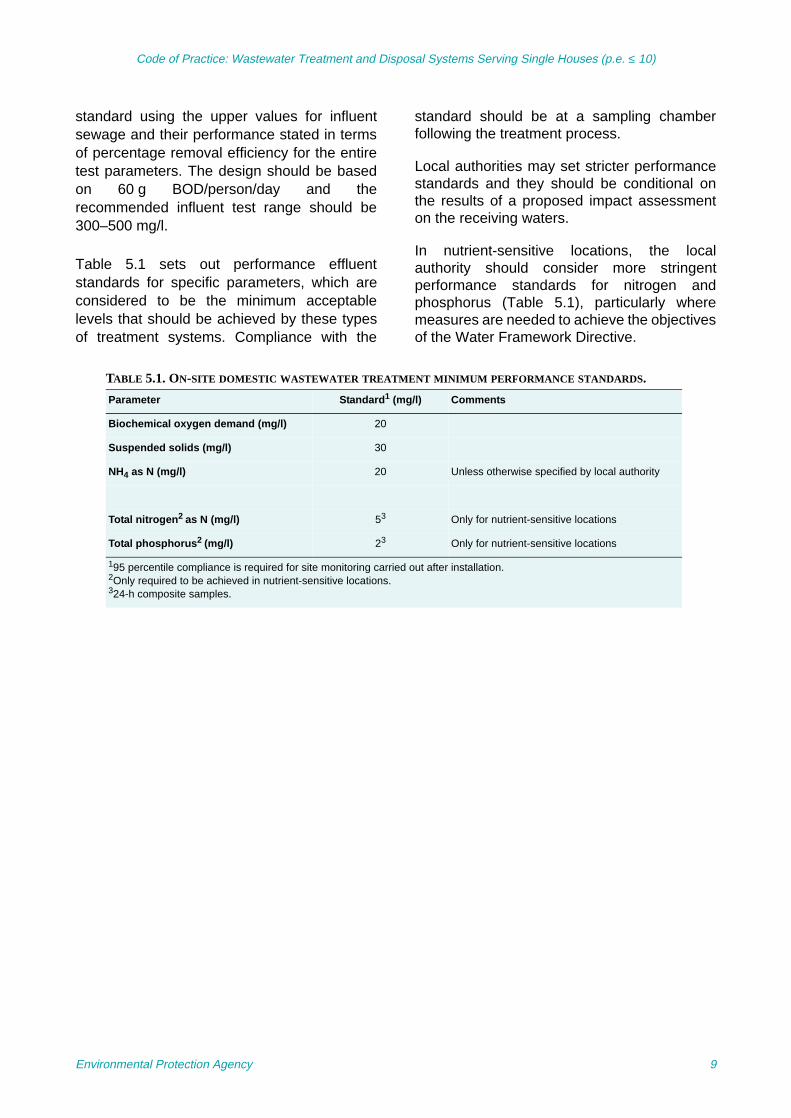
Table 5.1 sets out performance effluentstandards for specific parameters, which areconsidered to be the minimum acceptablelevels that should be achieved by these typesof treatment systems. Compliance with the
standard should be at a sampling chamberfollowing the treatment process.
Local authorities may set stricter performancestandards and they should be conditional onthe results of a proposed impact assessmenton the receiving waters.
In nutrient-sensitive locations, the localauthority should consider more stringentperformance standards for nitrogen andphosphorus (Table 5.1), particularly wheremeasures are needed to achieve the objectivesof the Water Framework Directive.
TABLE 5.1. ON-SITE DOMESTIC WASTEWATER TREATMENT MINIMUM PERFORMANCE STANDARDS.
Parameter Standard1 (mg/l) Comments
Biochemical oxygen demand (mg/l) 20
Suspended solids (mg/l) 30
NH4 as N (mg/l) 20 Unless otherwise specified by local authority
Total nitrogen2 as N (mg/l) 53 Only for nutrient-sensitive locations
Total phosphorus2 (mg/l) 23 Only for nutrient-sensitive locations
195 percentile compliance is required for site monitoring carried out after installation.2Only required to be achieved in nutrient-sensitive locations.324-h composite samples.
Environmental Protection Agency 9

Code of Practice: Wastewater Treatment and Disposal Systems Serving Single Houses (p.e. ≤ 10)
6 Site Characterisation
The purpose of a site assessment is todetermine whether a site is suitable or not foran on-site wastewater treatment system. Theassessment will also help to predict thewastewater flow through the subsoil and intothe subsurface materials. The sitecharacterisation process outlined here isapplicable to the development of a single houseonly. More extensive site characterisation isrequired for cluster and large-scaledevelopments.
Risk can be defined as the likelihood orexpected frequency of a specified adverseconsequence. Applied for example togroundwater, a risk expresses the likelihood ofcontamination arising from a proposed on-sitetreatment system (called the source or hazard).A hazard presents a risk when it is likely to
affect something of value (the target, e.g.groundwater) (Fig. 6.1). It is the combination ofthe probability of the hazard occurring and itsconsequences that is the basis of riskassessment. Risk management involves siteassessment, selection of options andimplementation of measures to prevent orminimise the consequences and probability ofa contamination event (e.g. odour nuisance orwater pollution). The methodology for selectionand design of an on-site system in this codeembraces the concepts of risk assessment andrisk management.
The objective of a site characterisation is toobtain sufficient information from an in situassessment of the site to determine if an on-site domestic wastewater treatment systemcan be developed on the site. Each localauthority should satisfy itself that any personscarrying out these assessments are competentto do so (e.g. FETAC2 certified or equivalent3).
Under Article 22(2)(c) of the Planning andDevelopment Regulations 2006, where it isproposed to dispose of wastewater other than
All sites for proposed single houses in un-sewered rural areas should have a sitesuitability assessment carried out by acompetent person in accordance with therequirements of this section and the guidance inAnnex C. Where sites are deemed unsuitablefor discharge to ground, alternative options, ifany, will need to be discussed with the localauthority.
2. Further Education and Training Awards Council (FETAC).3. The local authority should assess qualifications on a case-
by-case basis and considering any developments in thetraining area.
FIGURE 6.1. SCHEMATIC OF SOURCE–PATHWAY–TARGET MODEL.
Environmental Protection Agency 10

Code of Practice: Wastewater Treatment and Disposal Systems Serving Single Houses (p.e. ≤ 10)
to a public sewer from a development proposedas part of a planning application to a planningauthority, the applicant must submit informationon the type of on-site treatment systemproposed and evidence as to the suitability ofthe site for the system proposed as part of thatplanning application.
To assist in the selection of the on-site systemand to standardise the assessment process, asite characterisation form has been prepared(Annex C.3). The completed form includingphotographs, site plans (including finished floorand ground levels), cross sections and designdetails should accompany all planningapplications for on-site domestic wastewatertreatment systems for single houses.
In designing an on-site domestic wastewatertreatment system to treat and dispose of thewastewater, three factors should beconsidered:
1. Are there any restrictions relating to thesite?
2. Is the site suitable to treat the wastewater?(Attenuation)
3. Is the site able to dispose of thewastewater volumes? (Hydraulic load)
Characterising the site involves a number ofstages and should include:
1. A desk study, which collects anyinformation that may be available on maps,etc., about the site
2. On-site assessment:
R A visual assessment of the site, whichdefines the site in relation to surfacefeatures
R A trial hole to evaluate the soil structure,mass characteristics such as preferentialflow paths, depth to bedrock and watertable
R Percolation tests that give an indicationof the permeability of the subsoil
3. Assessment of data obtained
4. Conclusion on the suitability of the site
5. Proposed disposal route, and
6. Recommendation for a wastewatertreatment system including on-site designrequirements.
Figure 6.2 summarises the general process tobe followed to select an on-site wastewatersystem discharging to ground and it is notintended to cover all scenarios.
6.1 Desk Study
The information collected from the desk studyas set out in Annex C.1 should be examinedand the following should be considered for alltreatment options.
Maximum number of residents: Thisinformation is available under general detailsand should be calculated using the number andsize of the bedrooms.
Proposed water supply: The proposed typeof water supply is required to determinewhether additional requirements are required.
Hydrological aspects include locating thepresence (if any) of streams, rivers, lakes,beaches, shellfish areas and/or wetlands whilehydrogeological aspects include:
• Soil type – type of drainage and depth towater table (information from Teagasc,EPA)
• Subsoil type – type of drainage and depth towater table (information from Teagasc,Geological Survey of Ireland (GSI), EPA)
• Location of karst features (information fromthe karst database, GSI)
• Aquifer type – importance of groundwaterand type of flow (this incorporates bedrocktype) (information from GSI)
• Vulnerability (information from GSI), and
• Groundwater protection responses(GWPRs) for on-site systems for singlehouses (Annex B).
Each site is specific and local factors andprevious experience of the operation of on-sitedomestic wastewater treatment systems in the
Environmental Protection Agency 11

Code of Practice: Wastewater Treatment and Disposal Systems Serving Single Houses (p.e. ≤ 10)
FIGURE 6.2. A GENERAL GUIDE TO THE SELECTION OF AN ON-SITE WASTEWATER TREATMENT SYSTEMDISCHARGING TO GROUND.
Environmental Protection Agency 12

Code of Practice: Wastewater Treatment and Disposal Systems Serving Single Houses (p.e. ≤ 10)
area (which could include checking the localauthority database for failed sites orcomplaints), density of existing development(iPlan system) and any water quality datashould be taken into account in using thisguideline information.
Presence of significant sites: Determinewhether there are significant archaeological,natural heritage and/or historical featureswithin the proposed site. To avoid anyaccidental damage, a trial hole assessment orpercolation tests should not be undertaken inareas that are at or adjacent to significant sites(e.g. archaeological features, National HeritageAreas (NHAs), Special Areas of Conservation(SACs), etc.), without prior advice from thelocal authority (e.g. heritage or conservationofficer) or the Heritage Service and NationalParks and Wildlife Service.
Nature of drainage: A high frequency ofwatercourses on maps indicates high orperched water tables.
Past experience: Is there evidence ofsatisfactory or unsatisfactory local experiencewith on-site treatment systems? Is there a veryhigh density of existing on-site domesticwastewater treatment systems in the area?What are the background nitrateconcentrations in groundwater?
6.2 On-Site Assessment
In addition to the requirements set out below,Annex C.2 provides more detailed guidance onhow to carry out an on-site assessment.
6.2.1 Visual assessmentThe purpose of the visual assessment is to:
1. Assess the potential suitability of the site
2. Assess potential targets at risk (e.g.adjacent wells), and
3. Provide sufficient information (includingphotographic evidence) to enable adecision to be made on the suitability of thesite for the treatment and discharge ofwastewater and the location of theproposed system within the site.
It is critical that all potential targets areidentified at this stage. The minimumseparation distances that should be used in thevisual assessment are set out in Table 6.1.These apply to all on-site domestic wastewatertreatment systems. If any of theserequirements cannot be met, on-site domesticwastewater systems cannot be developed onthe site. The recommended minimumdistances from wells and springs should satisfythe requirements of the groundwater protectionresponse (Annex B), which should have beenreviewed during the desk study and confirmedduring the on-site assessment. An on-sitedomestic wastewater treatment and disposalsystem should not be installed in a flood plainor in seasonally waterlogged, boggy orfrequently wetted areas.
All the information obtained during the visualassessment should be used to assist in thelocation of the trial hole and percolation testholes.
6.2.2 Trial hole assessmentThe purposes of the trial hole assessment areto determine:
• The depth of the water table
• The depth to bedrock, and
• The soil and subsoil characteristics.
The trial hole assessment will help to predictthe wastewater flow through the subsoil. Itshould be as small as practicable, e.g. 1 × 6 m(to allow sloped access), and should beexcavated to a depth of at least 1.2 m below theinvert of the lowest percolation trench (or 2 mfor GWPRs of R22 or higher). In the case of asloping site, it is essential that an estimate ofthe depth of the invert of the percolation trenchbe made beforehand. Details on how to carryout the trial hole assessment are given inAnnex C.2.
The soil characteristics that should beassessed are: texture, structure, presence ofpreferential flow paths, density, compactness,colour, layering, depth to bedrock and depth tothe water table. The soil texture should becharacterised using the classification includedin Annex C.3.2. Every significant layer
Environmental Protection Agency 13

Code of Practice: Wastewater Treatment and Disposal Systems Serving Single Houses (p.e. ≤ 10)
encountered in the trial hole should bedescribed in the Site Characterisation Form.(Further guidance is contained in Annex C andshould be adhered to.)
Photographic evidence of the trial hole and itsprofile should be provided to the relevantauthorities.
Where soil conditions are variable, further trialholes should be considered to help
characterise the site and identify areas ofimproved drainage.
If items of suspected archaeological interestare discovered, the relevant authorities shouldbe contacted.
6.2.2.1 Interpreting the trial hole test results
Table 6.2 sets out the subsoil characteristicsthat indicate the satisfactory characteristicsnecessary for the treatment of wastewater. Thepercolation characteristics will need to be
TABLE 6.1. MINIMUM SEPARATION DISTANCES IN METRES.
Septic tank, intermittent filters, packaged systems, percolation area, polishing filters (m)
Wells1 –
Surface water soakaway2 5
Watercourse/stream3 10
Open drain 10
Heritage features, NHA/SAC3 –
Lake or foreshore 50
Any dwelling house 7 septic tank 10 percolation area
Site boundary 3
Trees4 3
Road 4
Slope break/cuts 4
1See Annex B: Groundwater Protection Response.2The soakaway for surface water drainage should be located down gradient of the percolation area or polishing filterand also ensure that this distance is maintained from neighbouring storm water disposal areas or soakaways.
3The distances required are dependent on the importance of the feature. Therefore, advice should be sought fromthe local authority environment and planning sections (conservation officer and heritage officer) and/or from theDepartment of the Environment, Heritage and Local Government (DoEHLG), specifically the Archive Unit of theNational Monuments Section and the National Parks and Wildlife Service. If considering discharging to awatercourse that drains to an NHA/SAC the relevant legislation is Article 63 of the Habitats Directive. (NHA,National Heritage Area; SAC, Special area of Conservation.)
4Tree roots may lead to the generation of preferential flow paths. The canopy spread indicates potential rootcoverage.
TABLE 6.2. DEPTH REQUIREMENTS ON-SITE FOR ON-SITE SYSTEMS DISCHARGING TO GROUND.
Subsoil characteristics Minimum requirements
Minimum depth of unsaturated permeable subsoil below base of all percolation trenches for septic tank systems, i.e. minimum depth of unsaturated subsoil to bedrock and the water table
1.2 m1
Minimum depth of unsaturated permeable subsoil below the base of the polishing filter for secondary treatment systems, i.e. minimum depth of unsaturated subsoil to bedrock and the water table
0.9 m1
1Greater depths/thicknesses may be required depending on the groundwater protection responses (Annex B).
Environmental Protection Agency 14

Code of Practice: Wastewater Treatment and Disposal Systems Serving Single Houses (p.e. ≤ 10)
confirmed later by examining the percolationtest results.
6.2.3 Percolation testsA percolation (permeability) test assesses thehydraulic assimilation capacity of the subsoil,i.e. the ability of the subsoil to absorb water isassessed by recording the length of time for thewater level to drop in the percolation hole by aspecified distance. The objective of thepercolation test is to determine the ability of thesubsoil to hydraulically transmit the treatedeffluent from the treatment system, through thesubsoil to groundwater. The test also gives anindication of the likely residence time of thetreated effluent in the upper subsoil layers andtherefore it provides an indication of the abilityof the subsoil to treat the residual pollutantscontained in the treated effluent.
There are two types of percolation test: the T-test and the P-test. The T-test is carried out atthe depth of the invert of the percolation pipeand the P-test is carried out at the groundsurface. Detailed guidance for the carrying outof these percolation tests is given in AnnexC.2.3. The result of the percolation test isexpressed as either the T-value or the P-value.A minimum of three test holes per percolationtest should be excavated and tested at eachsite.
Where experience indicates that the site maybe borderline, then both T and P percolationtests should be carried out at the same time.
In situations where the T-test is in excess of 90then, irrespective of the P-test result, the site isunsuitable for discharge of treated effluent toground as outlined in this code, as it is likelyultimately to result in ponding due to theimpervious nature of the underlying subsoil (orbedrock). This guidance is consistent withSection 6.3 of I.S. CEN/TR 12566-2:2005. AllT-tests, where depth to bedrock or water tablepermits, should be completed to establish thisvalue (T > 90). The methodology for ashortened percolation test for low permeabilitysubsoils is found in Annex C.2.3.
In the case where there is a high water tablepresent then it is critical to assess the subsoillayer just above the water table by carrying out
a percolation test or particle size analysis of thesubsoil, thus determining whether or not thewater table is due to a low permeability subsoilor a naturally high water table due to the site’shydrological location.
The subsoil classifications from the trial holeshould be confirmed by the percolation testresults. If there is not a good correlation thenfurther examination should be undertaken todetermine which assessment accuratelyreflects the suitability of the site to treat anddispose of the effluent.
Percolation test holes should be locatedadjacent to, but not within, the proposedpercolation area. It is important to note that thetop of the percolation hole should be located asaccurately as possible to the same level as theinvert of the percolation pipe (as determined bythe trial hole results).
In the case where there is shallow bedrockpresent then an assessment of the permeabilityof the bedrock has to determine whether thesite can absorb the hydraulic load and thatponding will not result. Specialist advice maybe needed to conduct the most appropriatetests dependent on the bedrock (e.g. pumpingtests, falling head tests, etc.) in accordancewith BS 5930. This is particularly necessary inareas of un-weathered granite and other lowpermeability bedrock.
6.2.3.1 Interpretation of the percolation testsTable 6.3 outlines the interpretation of thepercolation test results.
6.2.4 Integration of desk study and on-siteassessment
The information gathered during the desk studyand the on-site assessment is used tocharacterise the site and used later to chooseand design an on-site system. An integratedapproach will ensure that the target(s) at riskare identified and protected. To assist in theselection of the on-site system and tostandardise the assessment process, a sitecharacterisation form has been prepared(Annex C.3). The completed form includingphotographic evidence, site plans and designdetails should accompany all planningapplications for on-site systems for single
Environmental Protection Agency 15

Code of Practice: Wastewater Treatment and Disposal Systems Serving Single Houses (p.e. ≤ 10)
houses. Note, if the GWPR is R23, thegroundwater quality needs to be assessed (seeAnnex B).
6.3 Discharge Route
The disposal route of the treated wastewaterneeds to be considered prior to deciding on thetype of treatment. For septic tank systems, thetreated wastewater discharges via theunsaturated subsoil in the percolation area togroundwater. In the case of filters, wetlandsystems and packaged treatment systems,where there is an indirect discharge togroundwater, a polishing filter is required.
The discharge of any sewage effluent towaters4 requires a licence under the Water
Pollution Acts 1977–1990, and local authoritiesassess such applications. However, it shouldbe noted that a soakage pit or similar method isnot an acceptable means for treating septictank effluent and does not comply with therequirements set out in this code.
The relevant local authority should consider theaccumulative loading from on-site domesticwastewater treatment systems, particularly inareas of high-density one-off housing.Guidance on dilution calculations is included inAnnex D.2.
Where sites are deemed unsuitable for thedischarge of effluent to ground it is generallydue to hydraulic reasons or high water tables.The failure could be as a result of impervioussoil and/or subsoil and/or poorly permeablebedrock, which may result in ponding on-site. Inthese cases, site improvement works are
4. Includes any (or any part of any) river, stream, lake, canal,reservoir, aquifer, pond, watercourse or other inland waters,whether natural or artificial.
TABLE 6.3. INTERPRETATION OF PERCOLATION TEST RESULTS.
Percolation test result
Interpretation
T > 90 Site is unsuitable for development of any on-site domestic wastewater treatment system discharging to ground. Site may be deemed suitable for treatment system discharging to surface water in accordance with WaterPollution Act licence.
T < 3 Retention time in the subsoil is too fast to provide satisfactory treatment. Site is unsuitable for secondary-treatedon-site domestic wastewater systems. However, if effluent is pretreated to tertiary quality then the site will be hydraulically suitable to assimilate thishydraulic load. P-test should be undertaken to determine whether the site is suitable for a secondary treatment system with apolishing filter at ground surface or overground. Sites may be deemed suitable for discharge to surface water in accordance with Water Pollution Act licence1.
3 ≤ T ≤ 50 Site is suitable for the development of a septic tank system or a secondary treatment system discharging togroundwater.
50 < T < 75 Wastewater from a septic tank system is likely to cause ponding at the surface of the percolation area. Not suitablefor a septic tank system.May be suitable for a secondary treatment system with a polishing filter at the depth of the T-test hole.
75 ≤ T ≤ 90 Wastewater from a septic tank system is likely to cause ponding at the surface of the percolation area. Not suitablefor a septic tank system.Site unsuitable for polishing filter at the depth of the T-test hole. P-test should be undertaken to determine whether the site is suitable for a secondary treatment system withpolishing filter, i.e. 3 ≤ P ≤ 75, at ground surface or overground.
P < 3 Retention time in the topsoil/subsoil insufficient to provide satisfactory treatment. However, if effluent is pretreatedto tertiary state then the site will be hydraulically suitable to assimilate the hydraulic load. Imported suitablematerial may be deemed acceptable as part of site improvement works
3 ≤ P ≤ 75
T not possible due to high water table
Site is suitable for a secondary treatment system with polishing filter at ground surface or overground.If the subsoil is classified as CLAY, carry out a particle size distribution and refer to I.S. CEN/TR 12566-2:2005.
1Most local authorities do not grant water pollution discharge licences to single dwellings and the site assessor is advised to contact the Environment Section for advice.
Environmental Protection Agency 16

Code of Practice: Wastewater Treatment and Disposal Systems Serving Single Houses (p.e. ≤ 10)
unlikely to render the site suitable for dischargeto ground and the only possible discharge routeis to surface water in accordance with a WaterPollution Act Licence5.
Where it is proposed to discharge wastewaterto any surface water, a Water Pollution Actdischarge licence is required and the localauthorities should assess the impact andsuitability of the discharge from the on-sitesystem to the receiving water. Guidance maybe found in Annex D.2 of this CoP and inSection F.1 of the EPA Waste Water DischargeLicensing Application Guidance Note (2008).
6.4 Selecting an Appropriate On-Site Domestic WastewaterTreatment and Disposal System
The information collected from the desk studyand on-site assessment should be used in anintegrated way to determine whether an on-sitesystem is feasible. If so, the type of system thatis appropriate and the optimal final disposalroute for the treated wastewater aredetermined at this stage. Depending on thecharacteristics of the site, more than one optionmay be available. In choosing the appropriatesystem for a site, the assessor should haveregard to the guidance provided in this CoP.
When selecting a suitable wastewatertreatment system, the designer should besatisfied that:
• The influent test load reflects the requireddesign loadings, and
• The size of the treatment system selected iscovered by the relevant test report.
A number of factors should be taken intoaccount in the selection process and these arepresented in Annex E.4.
As there is no minimum site size specified inthis CoP, the issue of density should be dealtwith using a precautionary approach by the
local authority and on a case-by-case basishaving regard to the existing groundwaterquality, and minimum separation distances inTable 6.1 and the dilution calculations in AnnexD.2.
6.5 Site Improvement Works
Site improvement works should only be carriedout under the supervision of a competentperson, as such works are technically difficult tocarry out correctly. A constructed soil filtersystem (raised mound) is not considered to besite improvement works as it is itself atreatment system. Guidance on siteimprovement works is contained in Annex F.
In many cases, site improvement works will notbe sufficient to enable the site to be used for asystem incorporating discharge to ground andit may be deemed unsuitable. Examples ofsites where site improvement works will not beacceptable are:
• Sites where the slope exceeds 1:8
• Sites where T is greater than 90, indicatinga high risk of ponding
• Sites where T is greater than 90 in shallowsubsoil and/or bedrock permeability is notsufficient to take the hydraulic load
• Water table <300 mm from surface wherethe subsoil/bedrock is impermeable
• Sites where the separation distancescannot be satisfied
• Sites where the bare bedrock is exposed.
Having carried out the required siteimprovement works the appropriate parts of thesite characterisation form should be re-completed and an assessment of the overallsuitability of the site can be made. A site cannotbe deemed to have passed the on-siteassessment if the recommendations includesignificant site improvement works. The sitecharacterisation form and details of the siteimprovement works including additional testingresults should be submitted to the planningauthority.
5. Most local authorities do not grant discharge licences forsingle dwellings; it is advisable to consult with theEnvironment Section of the local authority prior to examiningthis route further.
Environmental Protection Agency 17

Code of Practice: Wastewater Treatment and Disposal Systems Serving Single Houses (p.e. ≤ 10)
6.6 Recommendations
At this stage of the process the sitecharacterisation is complete; the types of on-site domestic wastewater treatment systemsand the discharge options that are suitable forthe site are known. In some cases, however,the site may be deemed unsuitable for theinstallation of an on-site domestic wastewatertreatment system.
When a site is deemed suitable the siteassessor should make a recommendation as tothe most appropriate on-site domesticwastewater treatment system for the particularsite under assessment including the dischargeroute.
The conclusions of the site characterisation willdictate the type and range of system(s) and thedesign requirements.
In all cases, the minimum construction/installation requirements should be included inthe site characterisation report.
Where there are limiting site factors presentthen additional attention should be given toproviding cross sections indicating invert levelsof pipework, etc.
The information should clearly show where theon-site domestic wastewater treatment systemshould be installed and also highlight anyspecial conditions, taking into account that thesite assessor may not be the person actuallyinstalling the system.
The type, location and installation requirementsfor each system should be very clearly set outin the report, highlighting the importance of sitelevels and integration of finished floor levelswith the site assessment and cross sectionsshowing drainage falls, soil depth below pipeinverts, etc.
If additional pages are required then attachthem to the end of the site characterisationform.
In the case of selecting a system for a holidayhome (see Annex G.5), consideration shouldbe given to the selection of a system that canadequately deal with periods of inactivity, i.e.where the house is unoccupied for a prolongedperiod.
This CoP should be applied to all newdevelopment. However, existing on-sitedomestic wastewater treatment systems mayfail to meet the performance requirements asset out in this CoP. When this occurs,corrective actions are necessary. Successfulrehabilitation requires knowledge of theperformance requirements, a sound diagnosticprocedure, and appropriate selection ofcorrective actions. Variances to the CoPrequirements may be considered by the localauthority when it is satisfied that the proposedupgrade will provide improved treatment andreduced environmental impact. The failure ofthe existing treatment and disposal systemneeds to be clearly identified and correctiveactions proposed having regard to therequirements of this CoP.
Environmental Protection Agency 18

Code of Practice: Wastewater Treatment and Disposal Systems Serving Single Houses (p.e. ≤ 10)
7 Septic Tank Systems
A septic tank system comprises a septic tank,with treatment and distribution of the effluent bymeans of a percolation area. Septic tanks areprimary settlement tanks providing a limitedamount of anaerobic digestion. The percolationpipes may be subsurface or at ground levelusing in situ subsoil for treatment. A septic tankshould meet the requirements of I.S. EN12566-1:2000/A1:2004 or I.S. EN 12566-4:2007, including their National Annexes, andshould be followed by a disposal systemmeeting the requirements of I.S. CEN/TR12566-2:2005, I.S. CEN/TR 12566-5:2008 orprEN 12566-6 or as per the guidance providedwithin this CoP.
7.1 Septic Tanks
I.S. EN 12566-1:2000/A1:2004 Small Waste-water Treatment Systems for up to 50 PT – Part1: Prefabricated Septic Tanks is a productstandard developed and published by CEN andadopted by the NSAI. The standard and itsNational Annex specify a range ofrequirements and test methods in relation toseptic tank design and performance that thetank should conform to. As the standard andwater tightness cannot be assured in line withI.S. EN 12566-1:2000/A1:2004, theconstruction of in situ septic tanks is notpermitted in this code.
Septic tanks may be assembled on-site if theycomply with the requirements of I.S. EN 12566-4:2007 Small Wastewater Treatment Systems
for up to 50 PT – Part 4: Septic TanksAssembled in situ from Prefabricated Kits andare installed in accordance with themanufacturer’s instructions. A plan and sectionof a typical septic tank system layout is given inFig. 7.1.
7.1.1 Septic tank design capacityThe septic tank should be of sufficient volumeto provide a retention time for settlement of theSS, while reserving an adequate volume forsludge storage (Fig. 7.2). The volume requiredfor sludge storage is the determining factor insizing the septic tank. This sizing depends onthe potential occupancy of the dwelling, whichshould be estimated from the maximumnumber of people that the house canaccommodate, and the number and type ofbedrooms. The minimum plan area for a singlebedroom can be taken as 6.5 m2 and for adouble bedroom as 10.2 m2.
The tank capacity should be calculated fromthe following formula:
C = 150 × P + 2000
where C is the capacity (l) of the tank and P isthe design population, with a minimum of fourpersons.
The septic tank installed should always equalor exceed this design capacity. A minimumcapacity of 2,600 l (2.6 m3) should be providedon sites where the population is less than four.This assumes that de-sludging of the septictank is carried out at least once in every 12-month period. An effluent screen on the outletis recommended.
In relation to tank size for prefabricated tanks,I.S. EN 12566-1:2000/A1:2004 states thatnominal sizes should be expressed at 1 m3
intervals with minimum nominal capacity being2 m3 (Table 7.1).
7.1.2 Hydraulic loading ratesThe hydraulic loading through the trench baseand sidewalls of the percolation trench is
Septic tank systems comprise a septic tank anda percolation area. The majority of thetreatment occurs in the percolation trenchesand in the underlying subsoil. These systemsprovide effective treatment and disposal ofdomestic wastewater when properly sized,sited, installed and maintained in accordancewith this code of practice. These systemsrequire greater depths of subsoil and a largerpercolation area than secondary treatmentsystems.
Environmental Protection Agency 19

Code of Practice: Wastewater Treatment and Disposal Systems Serving Single Houses (p.e. ≤ 10)
controlled by the biomat on the floor and sidesof the trench rather than by the subsoil itself(Annex E.1). The percolation rates, measuredas they are on virgin subsoil using clean water,cannot be used for the design of the hydraulic
distribution system and length of percolationtrench. The length of percolation trench iscalculated as a function of the number ofpersons for which the house is designed. Aloading rate of 20 l/m2/day is recommended for
FIGURE 7.1. PLAN AND SECTION OF LAYOUT OF SEPTIC TANK SYSTEM.
Environmental Protection Agency 20

Code of Practice: Wastewater Treatment and Disposal Systems Serving Single Houses (p.e. ≤ 10)
wastewater being discharged into a percolationarea to take into account the effect of thebiomat. The minimum length of the entirepercolation trench required is given in Table7.2.
7.2 Percolation Areas
7.2.1 GeneralThe most important component of a septic tanksystem is the percolation area (also called aninfiltration area) as it provides the majority ofthe treatment of the wastewater effluent. I.S.CEN/TR 12566-2:2005 Small WastewaterTreatment Systems for up to 50 PT – Part 2:Soil Infiltration Systems has been published bythe NSAI as a technical report giving guidancefor soil infiltration systems to be used with smallwastewater treatment systems. The contents ofthat document have been taken into account inthe preparation of this CoP. Where the detailedguidance in the two documents differs, e.g. in
relation to separation distances appropriate forplant, percolation areas, etc., the guidancegiven in this document is deemed moreappropriate to the Irish situation and should befollowed. Installation guidelines and layoutoptions are contained in Section 11.
In the percolation trench, the wastewater isallowed to flow by gravity into a distributiondevice, which distributes the flow evenly into aminimum of four percolation pipes in thepercolation trenches. The depth to the invert of
FIGURE 7.2. LONGITUDINAL SECTION OF A TYPICAL SEPTIC TANK (ALL DIMENSIONS IN MM).
TABLE 7.1. NOMINAL SEPTIC TANK CAPACITY FOR
VARIOUS DESIGN POPULATIONS.
Number of persons served Nominal capacity(m3)
2–5 3
6–10 4
TABLE 7.2. PERCOLATION TRENCH LENGTH.
Number of people in the house
Minimum length of trench1
(m)
4 72
5 90
6 108
7 126
8 144
9 162
10 180
1Trench width is 500 mm and no individual trench length should be more than 18 m.
Environmental Protection Agency 21
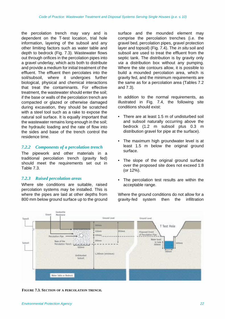
Code of Practice: Wastewater Treatment and Disposal Systems Serving Single Houses (p.e. ≤ 10)
the percolation trench may vary and isdependent on the T-test location, trial holeinformation, layering of the subsoil and anyother limiting factors such as water table anddepth to bedrock (Fig. 7.3). Wastewater flowsout through orifices in the percolation pipes intoa gravel underlay, which acts both to distributeand provide a medium for initial treatment of theeffluent. The effluent then percolates into thesoil/subsoil, where it undergoes furtherbiological, physical and chemical interactionsthat treat the contaminants. For effectivetreatment, the wastewater should enter the soil;if the base or walls of the percolation trench arecompacted or glazed or otherwise damagedduring excavation, they should be scratchedwith a steel tool such as a rake to expose thenatural soil surface. It is equally important thatthe wastewater remains long enough in the soil;the hydraulic loading and the rate of flow intothe sides and base of the trench control theresidence time.
7.2.2 Components of a percolation trenchThe pipework and other materials in atraditional percolation trench (gravity fed)should meet the requirements set out inTable 7.3.
7.2.3 Raised percolation areasWhere site conditions are suitable, raisedpercolation systems may be installed. This iswhere the pipes are laid at other depths from800 mm below ground surface up to the ground
surface and the mounded element maycomprise the percolation trenches (i.e. thegravel bed, percolation pipes, gravel protectionlayer and topsoil) (Fig. 7.4). The in situ soil andsubsoil are used to treat the effluent from theseptic tank. The distribution is by gravity onlyvia a distribution box without any pumping.Where the site contours allow, it is possible tobuild a mounded percolation area, which isgravity fed, and the minimum requirements arethe same as for a percolation area (Tables 7.2and 7.3).
In addition to the normal requirements, asillustrated in Fig. 7.4, the following siteconditions should exist:
• There are at least 1.5 m of undisturbed soiland subsoil naturally occurring above thebedrock (1.2 m subsoil plus 0.3 mdistribution gravel for pipe at the surface).
• The maximum high groundwater level is atleast 1.5 m below the original groundsurface.
• The slope of the original ground surfaceover the proposed site does not exceed 1:8(or 12%).
• The percolation test results are within theacceptable range.
Where the ground conditions do not allow for agravity-fed system then the infiltration
FIGURE 7.3. SECTION OF A PERCOLATION TRENCH.
Environmental Protection Agency 22

Code of Practice: Wastewater Treatment and Disposal Systems Serving Single Houses (p.e. ≤ 10)
TABLE 7.3. REQUIREMENTS OF A PERCOLATION TRENCH (GRAVITY FED).
Percolation trench characteristics Requirements
Slope of pipe from tank to distribution box
1 in 40 for earthenware or concrete1 in 60 for uPVC
Slope of percolation trench from distribution box
1 in 200
Length of percolation pipe in each trench 18 m maximum
Minimum separation distance between percolation trenches
2 m (2.5 m centre to centre)
Diameter of pipe from septic tank to distribution box
100–110 mm
Percolation pipes1 100 mm bore, perforated (typically at 4, 6 and 8 o’clock) smooth wall PVC drainage pipes with perforations of 8-mm diameter at about 75-mm centres along the pipe orPipes with similar hydraulic properties
Width of percolation trench 500 mm
Depth of percolation trench About 850-mm depth2 below ground surface depending on site (as per Fig. 7.3)
Backfilling of percolation trench (see Fig. 7.1)
300 mm of 8- to 32-mm washed gravel on invert; pipe laid at a 1 in 200 slope surrounded by 8- to 32-mm clean washed gravel and with 150 mm of similar gravel over pipe; geotextile layer followed by 300 mm topsoil to ground surface
Geotextile Geotextile should be in accordance with EN ISO 10319
Access/Inspection points and vents These are recommended for the ends of the percolation pipes; the covers should be visible and installed to prevent entry of water. They may also be used for rodding/scouring purposes
1Before installation the holes in the percolation pipe should be inspected to check that they are the correct size and free from debris.2The percolation pipes may be located at a shallower depth, provided that a minimum of 450 mm of material is placed above the pipesto provide the required protection against damage from above (Fig. 7.4).
FIGURE 7.4. RAISED PERCOLATION AREA.
Environmental Protection Agency 23

Code of Practice: Wastewater Treatment and Disposal Systems Serving Single Houses (p.e. ≤ 10)
(distribution) system should be as outlined foran intermittent soil filter in Section 8.
7.2.4 Other infiltration systemsOther infiltration systems not covered by anational or harmonised European Standard,such as drip-feed systems, non-aggregatesystems, leaching chambers, pressuremanifold and rigid pipe pressure networks,should be certified (certification may include aEuropean Technical Approval, an Agrément
Certificate or equivalent), be fit for the purposefor which they are intended, the conditions inwhich they are used, and meet theperformance requirements of this CoP for bothpercolation areas and polishing filters.
In all cases the manufacturer’s installationinstructions should be followed, and anauthorised contractor should install thesystems.
Environmental Protection Agency 24
Code of Practice: Wastewater Treatment and Disposal Systems Serving Single Houses (p.e. ≤ 10)
8 Secondary Treatment: Systems Constructed On-Site
This section deals with the topic of filtersystems constructed on-site including filtersystems and constructed wetland systems,while packaged on-site domestic wastewatertreatment systems are discussed in Section 9.Filter systems are used to provide additionaltreatment of the effluents from an upstreamseptic tank or package treatment unit. Thefilters can contain a variety of media, e.g. soil,sand, plastic, peat or gravel. They should bedesigned taking I.S. CEN/TR 12566-5:2008and this CoP into account.
prEN 12566-6 and prEN 12566-7 are inpreparation and will deal with the performancecharacteristics of prefabricated filters. In theinterim, these products should be certified(certification may include a EuropeanTechnical Approval, an Agrément Certificate orequivalent), be fit for the purpose for which theyare intended, the conditions in which they areused and meet the performance requirementsof this CoP.
A filter system comprises a septic tank followedby a pumping chamber, which transfers thepartially treated effluent onto the filter at regularintervals. A critical aspect of filter systems is theneed to dose the filter intermittently using apumped distribution system (Fig. 8.1). Thisfilter may comprise soil, sand, peat, textile orother media and is generally referred to as anintermittent filter system.
The partially treated effluent from a septic tankis further treated in the intermittent filter andthen discharged to ground, via a polishing filteror packaged tertiary treatment system, or insome cases to surface water. The purpose ofthe 0.9-m deep polishing filter is to provideadditional treatment of the effluent and toreduce pollutants such as micro-organisms andalso provide for the hydraulic conveyance ofthe treated effluent to ground. If the effluent isto be discharged to surface water, the requiredeffluent quality will be dictated by the conditionsof a water pollution discharge licence and sosome form of tertiary treatment either by apolishing filter or a packaged tertiary system(see Section 10) may be required.
In considering the construction of intermittentfilter systems and constructed wetlands, theuser should refer to the requirements of Section11. The maintenance requirements for thesesystems are set out in Section 12.
In the case of all intermittent filter systems, thefollowing applies:
• The wastewater from the intermittent filter isnormally collected in a chamber, fromwhere it is discharged to a polishing filter. Insome cases, the in situ subsoil underneaththe intermittent filter may have sufficientdepth on its own or with placed importedsoil to act as a polishing filter.
• In permeable sites, the filtrate from theintermittent filter, after passing through apolishing filter, may percolate into thegroundwater.
• In impermeable sites, the filtrate from theintermittent filter, after passing through apolishing filter/package tertiary treatmentsystem, may discharge to surface water inaccordance with a Water Pollution Actdischarge licence if permitted by the localauthority.
A constructed wetland system comprises aseptic tank followed by a constructed wetland
Secondary treatment filter systems comprisesystems that use different media constructedon-site to treat domestic wastewater. Apolishing filter is installed after these systems toallow for further treatment of the wastewaterand to convey the treated wastewater to waters.These systems may be suitable in areas wherea septic tank system is not acceptable. Thecode of practice provides general guidance onthe location, design, installation andmaintenance of these systems.
Environmental Protection Agency 25

Code of Practice: Wastewater Treatment and Disposal Systems Serving Single Houses (p.e. ≤ 10)
and polishing filter. Pumping may or may not berequired for a constructed wetland systemdependent on the slope and wetlandconfiguration.
The typical layout for the treatment ofwastewater using a filter or a constructedwetland system is illustrated in Fig. 8.2. Site
conditions will influence the requirement forpumping the wastewater through the differenttreatment units; however, intermittent filtersand some polishing filters will require pumping.
A competent person with relevant experiencein the area should carry out the design andconstruction of filter systems.
FIGURE 8.1. ILLUSTRATION OF A PUMPED DISTRIBUTION SYSTEM.
Environmental Protection Agency 26

Code of Practice: Wastewater Treatment and Disposal Systems Serving Single Houses (p.e. ≤ 10)
8.1 Soil Filter Systems
Soil filter systems may be used in situationswhere difficult site conditions are encountered,such as a shallow water table, insufficientsubsoil depth or insufficient percolationcharacteristics of native subsoil. A soil filtersystem may be developed through the use ofimported soil with favourable characteristics ormay be developed through the use of in situ soilwhere the upper layer has been removed andreplaced by a gravel distribution layer. In bothcases the septic tank effluent is distributed over
the filter using a pressure (i.e. pumped)distribution system (Fig. 8.1).
A soil filter may be placed in or on the ground ina number of different design formats. Typicaldesign and operational requirements are setout in Table 8.1.
• It may be placed in the ground with adistribution system installed at a shallowdepth.
• It may be arranged with the distributionsystem at ground level (Fig. 8.3).
FIGURE 8.2. ILLUSTRATION OF INTERMITTENT FILTER SYSTEM OR CONSTRUCTED WETLAND SYSTEM.
FIGURE 8.3. SCHEMATIC DIAGRAM OF AN INTERMITTENT SOIL FILTER.
Environmental Protection Agency 27

Code of Practice: Wastewater Treatment and Disposal Systems Serving Single Houses (p.e. ≤ 10)
TABLE 8.1. SOIL FILTER REQUIREMENTS.
Soil filter characteristics Requirements
Minimum soil thickness beneath invertof distribution system
1.2 m1
Soil percolation value2 In situ material should have a P/T-value between 3 and 75
Hydraulic loading 4 l/m2/day on plan area of filter
Design criteria3
Soil layers Lifts of 300 mm of soil (lightly compacted) when imported
Gravel protection layer 150 mm of 8- to 32-mm washed gravel
Infiltration laterals 32 mm ∅ PVC with 4- to 6-mm orifices4 at 0.3-m spacings
Gravel distribution layer 250 mm of 8- to 32-mm washed gravel
Lateral centres separation 0.6 m
Geotextile In accordance with EN ISO 10319
Underdrain/Collection system (required where T > 90 and proposed discharge is to surface water)
Washed durable gravel or stone 8–32 mmSlotted or perforated drain pipe ∅ 75–100 mm Slope 0–1%
Dosing frequency Minimum of four times per day (at equal time intervals for optimum treatment efficiency)
Pumping system Pumps should be installed in a separate pumping chamber and only suitable wastewater treatment pumps with a minimum free passage of 10 mm should be used
Zoned regions It is recommended that the manifold is designed to operate in at least two separate zones within any one polishing filter. This design facilitates maintenance should any problem occur and also allows sequential loading to different zones
Access/Inspection pointsBackpressure gauges
Recommended to be installed in the distribution system for rodding/scouring purposes. These vertically attached pipes to the manifold should extend to an inspection chamber and can also be used as a point to measure the backpressure of the system
In-line filter An in-line filter between the pump chamber and the infiltration pipe is recommended to prevent blockages in the orifices. It should be designed to have a mesh size of 10 mm
Side sealing
Mound system Topsoil on the top and the vertical sides should be protected by a geotextile
Below-ground system Impermeable liner required in free-draining in situ subsoils
Base sealing No sealer required.Ground base layer in mound systems to be ploughed/tilled5
Covering Geotextile over the gravel distribution layer300 mm topsoil over geotextile
1Greater thickness may apply – consult the groundwater protection response.2If constructing a mound system then the imported subsoil should have an in-situ T-value between 3 and 30.3Due to variations in the discharge rating of pumps available on the market, it is important to correctly match theorifice diameter and the lateral diameter in the distribution system to the pump, thus ensuring even and effectivedistribution of the hydraulic load across the filter area.
4The infiltration pipe should be laid with the holes facing downwards I.S. CEN/TR 12566-2:2005.5In the case of mound systems, the base should be roughened to minimise compaction and smearing of the soil(I.S. CEN/TR 12566-2:2005).
Environmental Protection Agency 28

Code of Practice: Wastewater Treatment and Disposal Systems Serving Single Houses (p.e. ≤ 10)
• It may be raised with the distribution systemabove the normal ground level.
8.2 Sand Filter Systems
Intermittent sand filters are an effective form ofon-site treatment. The wastewater treatmenttakes place under predominantly unsaturatedand aerobic conditions.
Two types of intermittent sand filters are used,namely, soil covered and open.
1. Soil-covered intermittent sand filters maybe underground, part underground andpart overground (Fig. 8.4) or overground.The latter two constructions are commonlyreferred to as mound systems.Maintenance is an issue and needs to beconsidered in the selection process.
2. Open intermittent sand filters areconstructed similar to the covered sandfilters, but without the soil cover, i.e. thegravel distribution layer is exposed at thesurface to allow for inspection and periodicmaintenance. They are preferablyunderground with the top of the gravel atground surface.
Intermittent sand filters are single-pass slowsand filters, which support biofilms. Typicaldesign details are shown in Table 8.2. Theyconsist of a number of beds of graded sandcommonly 700–900 mm deep, underlainnormally by a layer of filter gravel about 200-mm thick to prevent outwash or piping of thesand. A stratified sand filter is illustrated in Fig.8.5 (Nichols et al., 1997). Phosphorus removalis dependent on sand mineralogy; it should benoted that the ability of any sand to removephosphorus is finite (Zhu et al., 2003).
Even distribution across the entire surface areaof the intermittent sand filter is critical. In soil-covered filters, a non-clogging geotextile isused to separate the soil cover from thedistribution gravel. The wastewater from theseptic tank flows through the sand bed where itis treated.
In a soil-covered filter, both the distributiongravel over the sand and the drain filter gravel(where present) under the sand are vented; thevents are extended vertically above ground ormound level and capped with a cowl or grid. Inan open filter only the drain filter gravel (wherepresent) is vented.
FIGURE 8.4. INTERMITTENT SAND FILTER SYSTEM WITH UNDERLYING SAND/SUBSOIL POLISHING FILTER.
Environmental Protection Agency 29

Code of Practice: Wastewater Treatment and Disposal Systems Serving Single Houses (p.e. ≤ 10)
TABLE 8.2. SAND FILTER REQUIREMENTS.
Sand filter characteristics Requirements
Minimum sand thickness 0.7–0.9 m
Sand grain sizes Soil covered – D10 range from 0.7 to 1.0 mm Open filters – D10 range from 0.4 to 1.0 mmUniformity coefficients (D60/D10) less than 4
Hydraulic loading 20 l /m2/day (based on plan area) if 3 < P/T < 2010 l /m2/day (based on plan area) if 21< P/T< 75
Design criteria1
Sand layers A number of beds of graded sand
Gravel protection layer 150 mm of 8- to 32-mm washed gravel
Infiltration laterals 32 mm ∅ PVC with 4- to 6-mm orifices2 at 0.3-m spacings
Gravel distribution layer 250 mm of 8- to 32-mm washed gravel
Lateral centres separation 0.6 m
Underdrain/Collection system (required where T > 90 and required to dischargeto surface water or offset polishing filter is proposed)
Washed durable gravel or stone 8–32 mmSlotted or perforated drain pipe ∅ 75–100 mm Slope 0–1%
Dosing frequency (controlled by on/off levels on pump)
Minimum of four times per day (at equal time intervals for optimum treatment efficiency)
Pumping system Pumps should be installed in a separate pumping chamber and only suitable wastewater treatment pumps with a minimum free passage of 10 mm should be used
Side sealing
Mound system Topsoil on the top and the vertical sides should be protected by a geotextile
Below-ground system Impermeable liner in free-draining in situ subsoils
Base sealing
Offset polishing filter Impervious soil or synthetic liner with collection system
Covering
Soil covered Geotextile (in accordance with EN ISO 10319) over the gravel distribution layer and 300 mm topsoil over geotextile
Open None
Venting
Soil covered Both distribution gravel and drain filter gravel are vented
Open filter Drain filter gravel is vented
Access/Inspection points Recommended to be installed in the distribution system for rodding/scouring purposes
1Due to variations in the discharge rating of pumps available on the market, it is important to correctly match theorifice diameter and the lateral diameter in the distribution system to the pump, thus ensuring even and effectivedistribution of the hydraulic load across the filter area.
2The infiltration pipe should be laid with the holes facing downwards I.S. CEN/TR 12566-2:2005.
Environmental Protection Agency 30

Code of Practice: Wastewater Treatment and Disposal Systems Serving Single Houses (p.e. ≤ 10)
8.3 Drainage and Sealing of FilterSystems
In the case of overground intermittent filters,the collector drains to remove the filtrate areexcavated into the top of the impervious layerat appropriate spacings and drainage pipes arelaid and backfilled with filter gravel to originalground surface. The treated effluent should becollected in a collection chamber anddischarged to a polishing filter or to surfacewater in accordance with a licence. Thedischarge of filtrate to surface water requires awater pollution discharge licence.
An impermeable liner is used to seal off thesides of the intermittent filter to preventpossible bypass into gravelly soil when the filteris underground; this bypass could occur whena flooding dose is applied to the distributiongravel. Where the polishing filter is offset, theentire intermittent filter should be enclosed(Fig. 8.6) in a leak-proof liner.
8.4 Mounded Intermittent FilterSystems
Where shallow bedrock or a high water tableexists, a mounded intermittent soil or sand filter
as illustrated in Fig. 8.7 may provide therequired solution to the on-site treatment ofwastewater.
At a minimum, the following site conditionsshould exist:
• There is at least 0.3 m of naturally occurringsoil above the bedrock.
• The maximum high groundwater level is atleast 0.3 m below the natural groundsurface.
• The slope of the original ground surfaceover the proposed site does not exceed 1:8(or 12%).
• The percolation test results for theunderlying subsoil are within the acceptablerange (3 ≤ T ≤ 75) or, where shallowbedrock is present, an assessment showingthat the site can absorb the hydraulic load.
In the case of a soil filter, the followingprocedure should be followed:
• Where soil (10 < T < 30) has to beimported, it should be placed in lifts in theproposed percolation area such that there is
FIGURE 8.5. SCHEMATIC CROSS SECTION OF STRATIFIED SAND FILTER.
Environmental Protection Agency 31
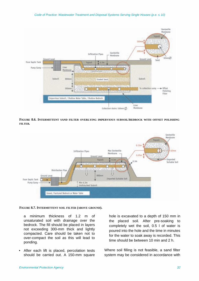
Code of Practice: Wastewater Treatment and Disposal Systems Serving Single Houses (p.e. ≤ 10)
a minimum thickness of 1.2 m ofunsaturated soil with drainage over thebedrock. The fill should be placed in layersnot exceeding 300-mm thick and lightlycompacted. Care should be taken not toover-compact the soil as this will lead toponding.
• After each lift is placed, percolation testsshould be carried out. A 150-mm square
hole is excavated to a depth of 150 mm inthe placed soil. After pre-soaking tocompletely wet the soil, 0.5 l of water ispoured into the hole and the time in minutesfor the water to soak away is recorded. Thistime should be between 10 min and 2 h.
Where soil filling is not feasible, a sand filtersystem may be considered in accordance with
FIGURE 8.6. INTERMITTENT SAND FILTER OVERLYING IMPERVIOUS SUBSOIL/BEDROCK WITH OFFSET POLISHING
FILTER.
FIGURE 8.7. INTERMITTENT SOIL FILTER (ABOVE GROUND).
Environmental Protection Agency 32

Code of Practice: Wastewater Treatment and Disposal Systems Serving Single Houses (p.e. ≤ 10)
criteria in Table 8.2 or alternative systemsfollowed by a polishing filter may be suitable.
It may, depending on site conditions, benecessary to pump the septic tank effluent to ahigher level before distribution over theinfiltration area. There are two options fordistribution of the septic tank effluent: dosingusing a pumped distribution system (Fig. 8.1and Table 8.1) or by pumping to a distributionchamber and then use a gravity-fed system(Tables 7.2 and 7.3).
In the case of a gravity system, it isrecommended to pump the effluent to a stillingchamber from where the effluent flows bygravity to a distribution device (as in Section11). In this case, the length of gravity pipe fromthe stilling chamber to the box should begreater than 3 m. The effluent from the septictank should not be pumped to an elevateddistribution device and then gravity fed on thetop of the mound. Pumping to a distributiondevice will not allow for even distribution of theeffluent; however, pumping to a sump/stillingchamber, which then discharges to adistribution device, may be acceptable. Thepumping chamber should be fitted with a high-level alarm to alert the homeowner to apossible pump failure or blocked distributionpipework, and vertical monitoring tubes(piezometers) should be inserted to determineif the mound starts to become saturated and toback up (see Section 12 on maintenance).
8.5 Application of Wastewater toFilter Systems
The wastewater from the on-site wastewatertreatment system should be applied uniformlyto the surface of the filter at intervals such thatthe wastewater percolates down through thecomplete surface area of the filter at a rate thatoptimises distribution (and treatment) onto thebiofilm coating the media. Even distributionmay be obtained by pumping the wastewaterthrough evenly spaced lateral pipes with evenlyspaced orifices embedded in distributiongravel, as detailed in Tables 8.1 and 8.2.Dosing frequencies are related to the type offilter medium. A minimum dosing frequency offour times daily is recommended, which shouldideally be applied at equal intervals by means
of a timer. Dosing tanks (pump sumps) shouldbe sized according to the volume of effluentproduction equivalent to one day’s volume fromthe household.
Other configurations and design distributionsystem specifications, such as rigid pipepressure networks, may be considered on acase-by-case basis. The design should be inaccordance with best practice and in line withpublished design manuals.
8.6 Constructed Wetlands
Constructed wetland is the generic term usedto describe both (gravel- and sand-based)horizontal and vertical flow reed bed systemsand soil-based constructed wetlands. Aconstructed wetland (a form of filter system) isanother option for the treatment of wastewaterfrom a septic tank. The main differencebetween a constructed wetland and other filtersystems is the planting of vegetation in themedia where the thick root mass acts as apathway for the transfer of oxygen from theatmosphere to the root zone (rhizosphere).
Plants used are emergent macrophytes, themost notable of which is the common reed(Phragmites australis). Other plants speciesused are Iris, Typha, Sparganium, Carex,Schoenoplectus and Acorus. Planting shouldoccur in blocks of plant species at a density offour to five plants per metre squared. A mixingof plant species is also encouraged to promotediversification in the system. Constructedwetlands can be designed to fit aestheticallywithin the landscape.
The mechanism and characteristics of eachindividual reed bed type play an important rolein their treatment performance. The mostcommon type of reed bed is the subsurfacehorizontal flow reed bed (i.e. a subsurface flowsystem, SFS) where the wastewater ismaintained below the surface of the wetlandmedia. It can further be subdivided dependingon medium selection and direction of flow:
• Horizontal flow reed beds (with gravel)
• Vertical flow reed beds (with gravel)
• Vertical flow reed beds (with sand).
Environmental Protection Agency 33
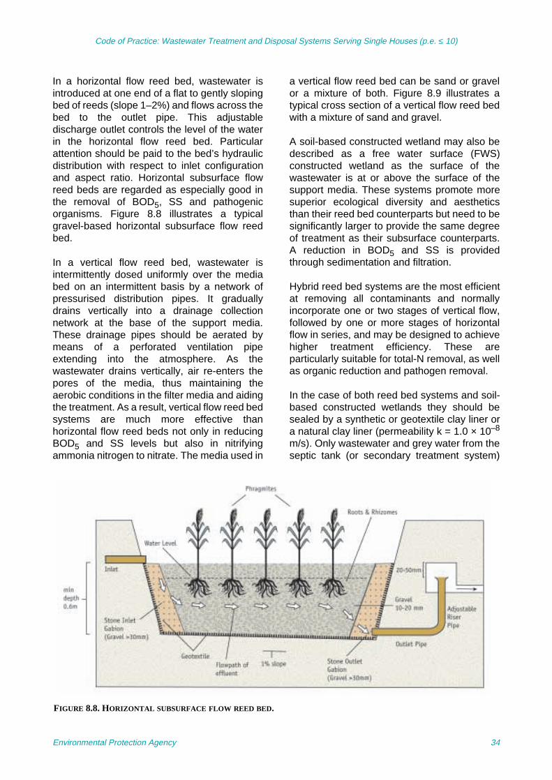
Code of Practice: Wastewater Treatment and Disposal Systems Serving Single Houses (p.e. ≤ 10)
In a horizontal flow reed bed, wastewater isintroduced at one end of a flat to gently slopingbed of reeds (slope 1–2%) and flows across thebed to the outlet pipe. This adjustabledischarge outlet controls the level of the waterin the horizontal flow reed bed. Particularattention should be paid to the bed’s hydraulicdistribution with respect to inlet configurationand aspect ratio. Horizontal subsurface flowreed beds are regarded as especially good inthe removal of BOD5, SS and pathogenicorganisms. Figure 8.8 illustrates a typicalgravel-based horizontal subsurface flow reedbed.
In a vertical flow reed bed, wastewater isintermittently dosed uniformly over the mediabed on an intermittent basis by a network ofpressurised distribution pipes. It graduallydrains vertically into a drainage collectionnetwork at the base of the support media.These drainage pipes should be aerated bymeans of a perforated ventilation pipeextending into the atmosphere. As thewastewater drains vertically, air re-enters thepores of the media, thus maintaining theaerobic conditions in the filter media and aidingthe treatment. As a result, vertical flow reed bedsystems are much more effective thanhorizontal flow reed beds not only in reducingBOD5 and SS levels but also in nitrifyingammonia nitrogen to nitrate. The media used in
a vertical flow reed bed can be sand or gravelor a mixture of both. Figure 8.9 illustrates atypical cross section of a vertical flow reed bedwith a mixture of sand and gravel.
A soil-based constructed wetland may also bedescribed as a free water surface (FWS)constructed wetland as the surface of thewastewater is at or above the surface of thesupport media. These systems promote moresuperior ecological diversity and aestheticsthan their reed bed counterparts but need to besignificantly larger to provide the same degreeof treatment as their subsurface counterparts.A reduction in BOD5 and SS is providedthrough sedimentation and filtration.
Hybrid reed bed systems are the most efficientat removing all contaminants and normallyincorporate one or two stages of vertical flow,followed by one or more stages of horizontalflow in series, and may be designed to achievehigher treatment efficiency. These areparticularly suitable for total-N removal, as wellas organic reduction and pathogen removal.
In the case of both reed bed systems and soil-based constructed wetlands they should besealed by a synthetic or geotextile clay liner ora natural clay liner (permeability k = 1.0 × 10⁻⁸
m/s). Only wastewater and grey water from theseptic tank (or secondary treatment system)
FIGURE 8.8. HORIZONTAL SUBSURFACE FLOW REED BED.
Environmental Protection Agency 34

Code of Practice: Wastewater Treatment and Disposal Systems Serving Single Houses (p.e. ≤ 10)
should be allowed to enter the wetland, i.e. nocollected rainwater or surface water ispermitted. In all cases these wetland systemsshould be fenced off or landscaped to preventany unauthorised access particularly bychildren or animals.
The design of a reed bed or soil-basedconstructed wetland is site specific. Acompetent person should undertake the designand installation of a constructed wetland. Thefollowing provides general guidance on thesetypes of systems but does not give all possibledesign options. The guidance EN 12566 SmallWastewater Treatment Systems for up to 50 PT– Part 5: Pre-Treated Effluent Filtration
Systems refers to constructed wetlands andreed beds as open filters with reeds. I.S.CEN/TR 12566-5:2008 is a useful reference forfurther details on reed bed systems but aspecialist should always be consulted. Allconstructed wetlands require periodicmaintenance, which is detailed in Section 11.
8.6.1 Design Considerations
All constructed wetlands should be designedfor a minimum of 5 p.e. for use as secondarywastewater treatment systems. Other designconsiderations are included in Table 8.3. Thesizing of these treatment systems is ultimatelydependent on the quality of the receiving water
FIGURE 8.9. VERTICAL SUBSURFACE FLOW REED BED.
TABLE 8.3. CRITERIA FOR CONSTRUCTED WETLAND SYSTEMS RECEIVING SEPTIC TANK EFFLUENT.
System type Area required Minimum system size
Loading rates Length/Width ratio
Horizontal flow reed bed – gravel (SFS)
5 m2/p.e. 25 m2 – 3:1
Vertical flow reed bed – gravel (SFS)
1.5–3 m2/p.e. 15 m2 8 l/m2 per dose (maximum) 2.5:1
Vertical flow reed bed – sand (SFS)
5–6 m2/p.e. 25 m2 5–15 l/m2 per dose for 2–5 doses per day
2.5:1
Soil-based constructed wetland (FWS)
20 m2/p.e. 100 m2 – 5:1
Environmental Protection Agency 35

Code of Practice: Wastewater Treatment and Disposal Systems Serving Single Houses (p.e. ≤ 10)
and therefore increased sizes are required innutrient-sensitive areas.
For systems on sloping ground, it can bebeneficial to divide the required bed area into anumber of smaller beds. Multiple bedsnecessitate additional controls, but increaseflexibility of use and enable resting andmaintenance of beds to be more easily carriedout. Other treatment equipment, e.g. storageponds, maturation ponds, willows, etc., may beadded to the system to enhance further
treatment. The landscape setting mayinfluence the design of these systems toprovide secondary or tertiary treatment ofwastewater.
A polishing filter should follow these systemswhen the disposal route for the secondary-treated effluent is to groundwater. In the casewhere these systems discharge directly tosurface water, a Water Pollution Act dischargelicence is required.
Environmental Protection Agency 36

Code of Practice: Wastewater Treatment and Disposal Systems Serving Single Houses (p.e. ≤ 10)
9 Secondary Treatment: Packaged Wastewater Systems
A treatment system should meet therequirements of I.S. EN 12566-3:2005 SmallWastewater Treatment Systems for up to 50 PT– Part 3: Packaged and/or Site AssembledDomestic Wastewater Treatment Plants and befollowed by a disposal system meeting therequirements of I.S. CEN/TR 12566-2:2005 orI.S. CEN/TR 12566-5:2008 or as per theguidance provided within this CoP. Packagedwastewater systems may be used to treatwastewater from a dwelling house. The effluentfrom all packaged systems should be treatedon a polishing filter where the final discharge isto groundwater, or a treatment system couldalso comprise a product meeting therequirements of I.S. EN 12566-3:2005,followed by a reed bed or system meeting therequirements of prEN 12566-7 withdemonstrated performance requirementsproducing the required effluent quality for directdisposal to surface water with an appropriatedischarge licence.
Many systems are available on the market andinclude the following generic treatmentprocesses:
• Activated sludge (incl. extended aeration)systems
• Biological/Submerged aerated filter (BAF/SAF) systems
• Rotating biological contactor (RBC)systems
• Sequencing batch reactor (SBR) systems
• Peat filter media systems
• Plastic, textile and other media systems
• Membrane bioreactor (MBR) systems.
Where such products are used they shouldconform to the relevant Part of the EN 12566series of standards. prEN 12566-6 and prEN12566-7 are in preparation and will deal withthe performance characteristics ofprefabricated filters. Where the relevant part ofEN 12566 is not yet available, products shouldbe certified (certification may include aEuropean Technical Approval, an AgrémentCertificate or equivalent), be fit for the purposefor which they are intended, the conditions inwhich they are used and meet the performancerequirements of this CoP.
Packaged wastewater treatment systemscomprise several components some of whichare mechanical and/or electrical. Thesesystems require regular monitoring andmaintenance. Generally such systems producea higher-quality effluent in terms of organicsand micro-organisms as compared with septictank systems. Mechanical systems are oftenmore sensitive to grease loading so the use ofa grease trap may be recommended. Theirsludge storage capacity should be checkedwith the manufacturer at the time of purchase toestablish the necessary frequency of de-sludging. It is recommended that the tankshould have the capacity to store at least 1year’s sludge production and be de-sludgedonce per year. All wastewater treatmentsystems should be provided with an alarm toindicate operation failure in line with therequirements of I.S. EN 12566-3:2005.
Packaged wastewater systems use media andmechanical parts to enhance the treatment ofdomestic wastewater. As with filter systems,they require a polishing filter to allow for furthertreatment of the wastewater and to convey thetreated wastewater to groundwater. Thesesystems should be certified to specificperformance criteria and may be suitable inareas where a septic tank is not acceptable.The code of practice provides general guidanceon the location, design, installation andmaintenance of these systems.
Environmental Protection Agency 37

Code of Practice: Wastewater Treatment and Disposal Systems Serving Single Houses (p.e. ≤ 10)
9.1 Location of PackagedWastewater Systems
Recommended minimum distances ofseparation of packaged wastewater treatmentsystems and infiltration areas should be aslisted earlier in Table 6.1. The recommendedminimum distances from wells should satisfythe requirements of the GWPR (see Annex B),which should have been consulted as part ofthe site characterisation. The GWPRs may alsonecessitate that subsoil depths for polishingfilters/infiltration systems in excess of thoseindicated in this CoP may be required.
9.2 Biological Aerated Filter (BAF)Systems
A BAF system may consist of a primarysettlement tank, an aerated submerged biofilmfilter and a secondary settlement tank (Fig.9.1). Solids are sometimes returned from thesecondary settlement chamber to the primarysettlement chamber to facilitate de-sludgingand to avoid sludge rising due to de-nitrification. Normally BAF systems, which areused to treat wastewater from single dwellings,can be purchased as prefabricated units, withall chambers in one unit. BAF systems are
normally constructed in glass-reinforcedplastic, concrete or steel.
The micro-organisms are attached to the filtermedia in the secondary treatment stage. Themedia normally have a high specific surfacearea (m2/m3) and can consist of plasticmodules or a granular material. Where granularmedia are used the system may requirebackwashing to prevent clogging of porespaces.
Normally the BAF system providescarbonaceous oxidation but can be designed toprovide nitrification. Grease should not beallowed to enter the aerated zone.
9.3 Rotating Biological Contactor(RBC) Systems
An RBC system consists of a primarysettlement tank, a secondary treatmentcompartment and a secondary settlement tank(Fig. 9.2). In this system the micro-organismsare attached to an inert media surface (thedisc) and the inert media are mounted on ashaft that is rotated by an electric motor. Thesemedia are partially submerged in thewastewater. A biofilm develops on the mediaover time; it is this biofilm that treats the
FIGURE 9.1. SCHEMATIC OF A BIOLOGICAL AERATED FILTER SYSTEM (BAF).
Environmental Protection Agency 38

Code of Practice: Wastewater Treatment and Disposal Systems Serving Single Houses (p.e. ≤ 10)
wastewater. The settled sludge in thesecondary settlement tank is sometimesreturned to the primary settlement tank. RBCunits can be purchased as packaged treatmentunits for single dwellings; these units normallycontain all three compartments in one unit.Grease should not be allowed to enter thecontactor zone.
9.4 Sequencing Batch ReactorSystem (SBR)
The SBR (Fig. 9.3) process is a form ofactivated sludge treatment in which aeration,
settlement, and decanting can occur in a singlereactor. The process employs a five-stagecycle: fill, react, settle, empty and rest.Wastewater enters the reactor during the fillstage; typically, it is aerobically treated in thereact stage; the biomass settles in the settlestage; the supernatant is decanted during theempty stage; sludge is withdrawn from thereactor during the rest stage; and the cyclecommences again with a new fill stage. Forsingle-house systems, a primary settlementtank precedes the reactor. Grease should notbe allowed to enter the reactor.
FIGURE 9.2. SCHEMATIC OF A ROTATING BIOLOGICAL CONTACTOR (RBC) SYSTEM.
FIGURE 9.3. SCHEMATIC OF A SEQUENCING BATCH REACTOR (SBR) SYSTEM.
Environmental Protection Agency 39

Code of Practice: Wastewater Treatment and Disposal Systems Serving Single Houses (p.e. ≤ 10)
The successful operation of an SBR system isdependent on the reliable performance of atiming mechanism. It is important that regularchecks be made to ensure that the treatmentsequencing is occurring as designed.
Critical components of an SBR system includethe aeration/mixing process, the decantprocess, and the control process. SBRs can bemodified to improve the removal of nitrogenand phosphorus.
Since the SBR system provides batchtreatment of wastewater, it can accommodatewide variations in flow rates that are typicallyassociated with single houses.
9.5 Membrane Filtration Systems
Membrane filtration systems treat effluent bythe removal of both suspended solids anddissolved molecular material from the effluentas it passes across a specific membranematerial (Fig. 9.4). The system utilises atreatment tank with aeration and membranefiltration units. These systems usually producevery high quality effluents. The specialmembrane used is mounted on a support frameand, in order for the effluent to progress fromthe inlet end of the system to the outlet end, it
should pass through the membrane unit.Aeration equipment fitted within the treatmentunit performs a dual function – aerobicconditions are maintained and the membraneis constantly cleaned by the passage of air overits surface.
The integrity of the membrane filter fabric iscritical to the proper operation of the system.Membrane failure is usually determined by lighttransmittance instrumentation and anassociated alarm mechanism. The membranefabric should be subjected to regularmaintenance/repair and inspected for damageas the latter will impede performance.
These systems need to be cleaned (thefrequency of which is determined by way of apressure differential detector) and, according tothe current industry standard, replaced onceevery 10 years on average.
9.6 Media Filter Systems
9.6.1 Peat media filter systemsFibrous peat filters are used as intermittentopen filters to treat septic tank wastewater (Fig.9.5). A peat filter typically consists of adistribution system, the peat treatment mediaand a drain. Septic tank wastewater is
FIGURE 9.4. SCHEMATIC LAYOUT OF A MEMBRANE FILTRATION SYSTEM.
Environmental Protection Agency 40
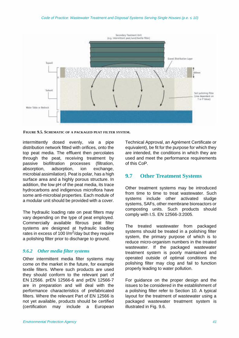
Code of Practice: Wastewater Treatment and Disposal Systems Serving Single Houses (p.e. ≤ 10)
intermittently dosed evenly, via a pipedistribution network fitted with orifices, onto thetop peat media. The effluent then percolatesthrough the peat, receiving treatment bypassive biofiltration processes (filtration,absorption, adsorption, ion exchange,microbial assimilation). Peat is polar, has a highsurface area and a highly porous structure. Inaddition, the low pH of the peat media, its tracehydrocarbons and indigenous microflora havesome anti-microbial properties. Each module ofa modular unit should be provided with a cover.
The hydraulic loading rate on peat filters mayvary depending on the type of peat employed.Commercially available fibrous peat filtersystems are designed at hydraulic loadingrates in excess of 100 l/m2/day but they requirea polishing filter prior to discharge to ground.
9.6.2 Other media filter systems
Other intermittent media filter systems maycome on the market in the future, for exampletextile filters. Where such products are usedthey should conform to the relevant part ofEN 12566. prEN 12566-6 and prEN 12566-7are in preparation and will deal with theperformance characteristics of prefabricatedfilters. Where the relevant Part of EN 12566 isnot yet available, products should be certified(certification may include a European
Technical Approval, an Agrément Certificate orequivalent), be fit for the purpose for which theyare intended, the conditions in which they areused and meet the performance requirementsof this CoP.
9.7 Other Treatment Systems
Other treatment systems may be introducedfrom time to time to treat wastewater. Suchsystems include other activated sludgesystems, SAFs, other membrane bioreactors orcomposting units. Such products shouldcomply with I.S. EN 12566-3:2005.
The treated wastewater from packagedsystems should be treated in a polishing filtersystem, the primary purpose of which is toreduce micro-organism numbers in the treatedwastewater. If the packaged wastewatertreatment system is poorly maintained andoperated outside of optimal conditions thepolishing filter may clog and fail to functionproperly leading to water pollution.
For guidance on the proper design and theissues to be considered in the establishment ofa polishing filter refer to Section 10. A typicallayout for the treatment of wastewater using apackaged wastewater treatment system isillustrated in Fig. 9.6.
FIGURE 9.5. SCHEMATIC OF A PACKAGED PEAT FILTER SYSTEM.
Environmental Protection Agency 41

Code of Practice: Wastewater Treatment and Disposal Systems Serving Single Houses (p.e. ≤ 10)
FIGURE 9.6. ILLUSTRATION OF A PACKAGE SYSTEM AND POLISHING FILTER SYSTEM.
Environmental Protection Agency 42

Code of Practice: Wastewater Treatment and Disposal Systems Serving Single Houses (p.e. ≤ 10)
10 Tertiary Treatment Systems
The term tertiary treatment system includespolishing filters and packaged tertiarytreatment systems. This section deals primarilywith polishing filters, which provide a dualfunction of polishing the effluent and alsodisposing of the treated effluent intogroundwater and surface water.
10.1 Polishing Filters
All filter systems (with the exception of soilfilters), constructed wetlands and packagedwastewater systems require a polishing filter(also known as a type of infiltration system)following the secondary treatment stage. Thepolishing filter can reduce micro-organisms andphosphorus (depending on soil type) inotherwise high-quality wastewater effluents.However, it should be noted that thephosphorus adoption capacity of any polishingfilter medium will become saturated with timeand its removal efficiency will reduce. The long-term effectiveness of the media should beassessed and monitored where the filter isbeing used to reduce phosphorus (Zhu et al.,2003).
All polishing filters should have a minimumthickness of 0.9 m of free-draining unsaturatedsoil or sand between the point of infiltration ofthe effluent and the water table and bedrock.They may be below, at ground surface orpartially or totally above ground surface.
The polishing filter produces a high qualityeffluent as it contains a reduced organic loadfrom secondary treatment systems comparedwith septic tank systems, and thus the biomat isless developed. This results in shorter trenchlengths and overall area for polishing filters.The advice provided above allows effluent froma polishing filter to discharge to groundprovided the subsoil has a T-value <90 and a P-value between 3 and 75. The maximum pipelength is 10 m for gravity-fed systems.
Where the native soil at the site is impervious,a graded gravel layer with drains shouldunderlie the polishing filter and the polishedwastewater is then drained away in a suitablemanner using a gravity or pumped sumparrangement to a watercourse (in accordancewith a Water Pollution Act discharge licence).
Where a polishing filter is constructedoverground or in contact with a very permeablegravel or sand stratum in the soil and ispressure dosed into surface distribution gravel,the sides of the filter should be enclosed by animpervious liner to prevent bypass of floodingdoses directly to the ground surface orgroundwater.
Other types of infiltration systems may be usedas polishing filters if they comply with therequirements referred to in Section 7.2.4. Thelocation and installation of infiltration systemsare discussed in Section 11.
10.1.1 Soil polishing filters
Soil polishing filters may comprise in situ soil,improved soil and/or imported soil. These soils,which should have a minimum depth of 0.9 m,should have percolation values in the range of3–75 for in situ material and a P/T-value of 3–30 for imported material. Effluent may beloaded onto a soil-polishing filter by any one ofthree arrangements (direct discharge, pumpeddischarge or gravity pipe discharge).
In typical layouts the soil polishing filter:
Tertiary treatment systems provide additionaltreatment to wastewater from secondarytreatment systems. Polishing filters can reducethe number of micro-organisms present in thetreated wastewater while other packagedtertiary treatment systems can further reducenutrients and micro-organisms. The treatmentstandards to be achieved by these systems aredependent on the sensitivity of the receivingwaters. As with all treatment systems theyshould to be sited, installed and maintained inaccordance with the guidance in the code ofpractice and manufacturer’s documentation.
Environmental Protection Agency 43

Code of Practice: Wastewater Treatment and Disposal Systems Serving Single Houses (p.e. ≤ 10)
• May underlie an intermittent filter with theeffluent being spread out over a shallowdistribution gravel layer immediatelyunderlying the filter; any exposed polishingfilter area may be soil covered and grassed(Option 1)
• May be offset from a secondary treatmentunit; loading may be by a pumpedarrangement (Option 2); the entire filter maybe covered with soil and graded down, and
• May be offset from the secondary treatmentsystem; loading may be fed by gravity intopercolation trenches (Option 3).
Recommended loading rates and designvalues for a five-person house are given inTable 10.1. Areas and lengths for other personnumbers are pro rata, e.g. the requirements fora 10-person house will be twice that of a five-person house.
a) Option 1 – Direct discharge Direct discharge occurs where the treatmentplant lies directly above the polishing filter andis distributed using a shallow distribution graveland with direct discharge from the polishingfilter to groundwater (Fig. 9.5). The loadingrates on the soil should conform to thoserecommended in Table 10.1.
b) Option 2 – Pumped dischargeThe treated wastewater from the secondarytreatment unit is pumped to a manifold andpercolation pipes using typically 32 mm ∅laterals with 4–6 mm ∅ orifices (0.6 m apart) at0.6 m spacing between laterals facingdownwards over a 200-mm layer of gravel. The
detail design should conform to best practice asoutlined in design manuals. The loading ratesshould conform to those listed in Table 10.1.
c) Option 3 – Gravity discharge
In the case of loading a percolation area with aP/T-value of 1–75 through percolation trenchesa greater area of polishing filter than for Options1 and 2 is required. The length of percolationtrench in a polishing filter for secondary-treatedwastewater from a five-person household forthe different percolation values is shown inTable 10.1 (see Fig. 9.6). Treated wastewaterfrom the secondary filter should flow by gravityto a distribution box, which distributes the flowevenly into the several trenches which shouldbe 500 mm wide at 2-m spacing (2.5 m centreto centre) and designed according to thecriteria given in Table 7.2, with the exceptionthat the maximum length of each trench shouldnot exceed 10 m.
10.1.2 Sand polishing filters Sand polishing filters comprise single layer andstratified sand filters; they should be a minimumof 900 mm in thickness. In a typical layout,three layers of sand, comprising an upper layerof coarse sand and intermediate and lowerlayers of fine sand, are separated from eachother by a thin layer of washed pea-sizedgravel or broken stone. The hydraulic loadingshould not exceed 60 l/m2/day. The sand-polishing filter can be soil covered and sownwith grass.
The filter specifications of the range of sandssuitable for the polishing filter sand layers areshown in Table 10.2. Where the filter is soil
TABLE 10.1. MINIMUM SOIL POLISHING FILTER AREAS AND PERCOLATION TRENCH LENGTHS REQUIRED FOR A
FIVE-PERSON HOUSE.
P/T-values1 Direct and pumped discharge(Options 1 and 2)
Percolation trench discharge (500 mm wide) (Option 3)
Loading rate on plan area (l/m2/day)
Area required for five persons (m2)
Loading rate on trench area (l/m2/day)
Trench length required for five persons (m)
3–20 ≤20 ≥45 ≤50 ≥36
21–40 ≤10 ≥90 ≤25 ≥72
41–50 ≤5 ≥180 ≤25 ≥72
51–75 ≤3 ≥240 ≤16 ≥90
1The loading rate is dependent on the percolation rate and in the case of an imported mound then the higher of the P-value of the in-situsubsoil and of the imported material should be used to size the polishing filter.
Environmental Protection Agency 44

Code of Practice: Wastewater Treatment and Disposal Systems Serving Single Houses (p.e. ≤ 10)
covered and sown with grass, sands at theupper end of the grading shown in Table 10.2are recommended. Figure 8.5 is an example ofa stratified sand filter that can also be used asa polishing filter.
10.2 Constructed Wetlands
Reed beds and constructed wetlands may alsobe used as tertiary treatment systems fordomestic wastewater. They may includeshallow vegetated surface flow wetlands. Referto Section 8.6 for details on these systems.Table 10.3 provides recommendations for thedesign of wetland systems as tertiary treatmentsystems.
10.3 Packaged Tertiary TreatmentSystems
Packaged tertiary treatment systems (wherepermitted) will be required in a nutrient-sensitive area or where the discharge is tosurface water. There are a number of differenttypes of tertiary treatment systems on themarket. The type of system to be used isdependent on the site conditions, the level ofsecondary treatment and the requirements ofthe receiving waters. Tertiary treatmentsystems may provide removal of phosphorus,
nitrogen and pathogens from secondary-treated effluent prior to discharge to thewaterbody. Tertiary treatment systems includesand, peat or textile filters, packaged reedbeds, ozone and UV disinfection systems,membrane filtration systems and specificallydesigned nutrient removal systems.
prEN 12566-7 will be concerned with tertiarypackaged and/or site-assembled tertiarytreatment units for the treatment of secondaryeffluent. It will be concerned with therequirement standards, test methods, marking,and evaluation of conformity for tertiarysystems that have received secondary-treatedeffluent. The manufacturer of any system hasto make a declaration as to the tertiarytreatment efficiency of any packaged system.
Tertiary treatment systems, which form part ofsystems covered under I.S. EN 12566-3:2005and prEN 12566-7, should conform to therequirements of those standards.
Where the standards are not yet available,products should be certified (certification mayinclude a European Technical Approval, anAgrément Certificate or equivalent), be fit forthe purpose for which they are intended, theconditions in which they are used and meet theperformance requirements of this CoP.
TABLE 10.2. CRITERIA FOR SAND-POLISHING FILTER.
Design factor Design criteria
Pretreatment Minimum of secondary treatment
Top coarse sand layer1 Effective size (D10) 0.25–0.75 (mm); D60/D10 (Cu) < 4
Fine sand layers Effective size (D10) 0.15–0.25 (mm); D60/D10 (Cu) < 4
1USEPA (1999). Wastewater Technology Fact Sheet. Intermittent Sand Filters. EPA 832-F-99-067.
TABLE 10.3. CRITERIA FOR TERTIARY TREATMENT.
System type Area required1 Minimum system size
Loading rates Length/Width ratio
Horizontal flow reed bed – gravel (SFS)
1 m2/p.e. 5 m2 – 3:1
Vertical flow reed bed – gravel (SFS)
1 m2/p.e. 5 m2 8 l/m2 per dose (maximum) Can vary (but must ensure equal distribution)
Vertical flow reed bed – sand (SFS)
3 m2/p.e. 15 m2 5–15 l/ m2 per dose, for 2–5 doses per day
Can vary (but must ensure equal distribution)
Soil-based constructed wetland (FWS)
10 m2/p.e. 50 m2 – 5:1
1Greater sizing may be required when discharging to nutrient-sensitive waters.SFS, subsurface flow system; FWS, free-water surface.
Environmental Protection Agency 45
Code of Practice: Wastewater Treatment and Disposal Systems Serving Single Houses (p.e. ≤ 10)
11 Construction and Installation Issues
All materials used in the construction of theworks should comply with the requirements ofthe Building Regulations, 1991 (andsubsequent amendments), and the relevantTechnical Guidance Documents.
11.1 Septic Tanks and Pipework
Manufacturers should provide installationinstructions with each septic tank, includingdetails of data for plant installation, pipeconnections, commissioning and start-upprocess, and these should be adhered to.
Recommended minimum distances ofseparation of septic tanks and percolationareas and filters from a variety of features areshown in Table 6.1 and in the GWPR.
Methods employed to test such tanks should bein accordance with I.S. EN 12566-1:2000/A1:2004.
Septic tanks should be securely covered toprevent unauthorised access and ensureoperational safety.
Provision should be made for access for asludge tanker and maintenance equipment tode-sludge the tank. Care should be taken to
ensure that septic tanks are not located wherethey may be subjected to loads from vehiculartraffic movements.
The tank should rest on a uniform bearingsurface and the underlying soils should becapable of bearing the weight of the tank and itscontents. After setting the tank, levelling andjoining the drains from the house and the tankoutlet to the distribution box, the excavationaround the tank can be backfilled. Backfillingshould not proceed until the joints and the tankhave been sealed and tested for watertightness. The backfill material should be freeflowing and be added in lifts to ensure that thetank remains level. Backfilling aroundprefabricated tanks should be carried out inaccordance with manufacturer’s specificationsand standard engineering practices.
Provisions should be made so that flotation oftanks does not occur either during constructionor subsequent to commissioning of thetreatment system.
If excessive quantities of waste oil and fats arelikely to be disposed of in the effluent then theuse of grease traps should be considered priorto installation.
Installation should be supervised and certifiedby a competent person and work documentedfor future evidence.
11.1.1 Drain from house to septic tankThe drain to the septic tank should be at least100 mm in diameter. It may be of earthenware,concrete, uPVC or similar materials. It shouldbe jointed to give a watertight seal and shouldbe laid to the minimum gradients listed inTable 11.1.
It should be vented by means of a vent pipeabove the eaves of the house. A manholeshould be provided for rodding the drain (and atany change in drain direction) and should belocated within 1 m of the septic tank. The drainshould include, at an appropriate location, an
Correct construction and installation of allwastewater treatment and disposal systems,including septic tanks, package systems andinfiltration systems, are essential to ensureeffective treatment of domestic wastewater.Homeowners are ultimately responsible for theoperation and maintenance of their wastewatertreatment system (Section 70 of the WaterServices Act, 2007). However, the onus is onthe owner or builder to construct and install thewastewater treatment system in accordancewith the manufacturer’s instructions, planningpermission and any relevant conditionsattached thereto, and building regulations, andfor ensuring that the wastewater treatment anddisposal systems comply with appropriatestandards and guidelines.
Environmental Protection Agency 46

Code of Practice: Wastewater Treatment and Disposal Systems Serving Single Houses (p.e. ≤ 10)
access junction to facilitate a future connectionto a sewer network.
11.1.2 Drain from septic tank to percolationarea
The flow of the effluent from the septic tank tothe percolation area should take place via adistribution device. The drain from the septictank to the distribution device should be 100mm in diameter and should be made ofearthenware, concrete, uPVC or similarmaterials. The required slopes of the pipe fromtank to distribution device are given in Table7.3. It is essential that the pipe be sealed intothe septic tank to prevent effluent escapingfrom the system.
A typical distribution device comprises achamber, which divides the effluent from theseptic tank equally between the percolationpipes supplying the percolation area. Thedevice is a key part of the overall installationand careful attention should be paid to itsselection. It should be designed andconstructed to ensure equal distribution amongthe various percolation pipes. The distributionchamber should be laid on a stable foundation.It should be accurately levelled to ensure thatthe incoming effluent is evenly split and evenlydiverted to the outlet percolation pipes. This isachieved by different technologies such asweirs or tee-splitters or optimally by tippingbuckets. The distribution device requiresongoing maintenance and should be inspectedregularly.
The use of an ad hoc combination of sewerpipe and ancillary junctions (e g. swept tees,etc., which are commonly available in builder’ssuppliers) to create the flow split is notrecommended. The distribution device shouldbe provided with inspection covers and locatedsuch that it is easy to open, inspect and, ifnecessary, clean the inside of the box. Access
and inspection covers should be visible andflush with the ground surface without allowingthe entry of surface water. Regular inspectionsshould be carried out to ensure that the effluententering the box is allowed to pass through tothe percolation pipes without obstruction byextraneous materials and that the levelconditions of the box are maintained.
11.2 Secondary Treatment: PackageWastewater Systems
All packaged wastewater systems should beinstalled in accordance with the manufacturer'sinstructions. Installation should be supervisedand certified by a competent person and thework documented for future evidence.
11.3 Infiltration Systems
Infiltration systems comprise percolation areas,filter systems constructed on-site, andpolishing filters that discharge to ground. Thepercolation area is an integral part of a septictank system. A filter system constructed on-siteis a secondary treatment system andcomprises different filter media, while apolishing filter is the distribution mechanism ofa secondary treatment system, be it a filtersystem or a package treatment system. Whilethese infiltration systems have different designcriteria and components, the construction andinstallation factors for both are the same andtherefore are dealt with below. Refer toSections 7, 8 and 10 for the detailed design ofpercolation areas and polishing filters,respectively. Construction and installationmethods employed should be in accordancewith I.S. CEN/TR 12566-2:2005 or I.S. CEN/TR12566-5:2008. Location, construction andinstallation practices are critical to theperformance of infiltration systems.
11.3.1 Location of infiltration systemsThe risk of polluting groundwater wells isminimised when the infiltration system ishydraulically down gradient of any groundwatersources. Recommended minimum distances ofseparation of infiltration systems are listed inTable 6.1. The minimum separation distancesfor wells specified in Annex B should beadhered to in all cases. The GWPRs may also
TABLE 11.1. GRADIENTS FOR DRAIN TO SEPTIC TANK.
Drainpipe material Minimum
Earthenware 1 in 40
Concrete 1 in 40
uPVC 1 in 60
Environmental Protection Agency 47

Code of Practice: Wastewater Treatment and Disposal Systems Serving Single Houses (p.e. ≤ 10)
dictate that subsoil depths in excess of thoseindicated in this CoP may be required.
Storm-water drains, water mains, servicepipes, soakaways, access roads, driveways,paved areas or land drains should not belocated within or around the infiltration area.
A buffer strip of 1 m around the infiltration areashould be observed. The layout of theinfiltration system should make optimum use ofthe available site.
The growth of any type of tree or plant thatdevelops extensive root systems should belimited to a minimum distance of 3 m from theinfiltration area. This restriction also applies tothe cultivation of crops necessitating the use ofmachinery that is likely to disturb the infiltrationarea.
11.3.2 Site worksThe site of the infiltration system should bestaked and roped off before any constructionactivities begin to make others aware of the siteand to keep traffic and materials off the site.Trenches should be backfilled as soon aspossible after excavation.
Earth-moving machinery should not circulateover the infiltration area before or, moreimportantly, after pipework and backfilling oftrenches has been completed. The area shouldbe clearly marked for the duration of anysubsequent site works.
Satisfactory performance of infiltration systemsdepends on maintaining soil porosity.Construction activities can significantly reducethe porosity and cause systems to hydraulicallyfail soon after being brought into service. Goodconstruction practices should carefullyconsider site preparation (before and duringconstruction) and equipment use.
Earthworks should ideally be carried out duringperiods of dry weather. Excavation activitiescan cause significant reduction in soil porosityand permeability. Compaction and smearing ofthe soil infiltrative surface occur fromequipment traffic and vibration and scrapingactions of the equipment. All efforts should bemade to avoid any disturbance to the exposedinfiltration surface. Any smeared areas should
be scarified with a rake and the surface gentlyraked. The gravel should be placed usingbuckets rather than from the truck itself.
11.4 Installation
Attention should be given to the impact of slopeand subsoil layering on the location of the invertof the percolation pipe. Where unsaturatedsubsoil depth is limiting, it may be possible tochoose a percolation pipe invert level that isnear or at the ground surface in order to fullyexploit the available subsoil depth. In suchcases it will be necessary to provide protectionfor the percolation pipework, when installed, byplacing soil over the pipework in sufficientquantities (minimum of 150 mm gravel and 300mm topsoil) to ensure that damage due toactivities on the surface does not occur.
There should be a maximum of five trenchesattached to each distribution box whendesigning a gravity system for a percolationarea. Figure 11.1 contains alternative layoutsto that in Section 7, which may be considereddepending on the site layout.
On sloping sites (slope >1:20 or 5%) thepipework should be installed parallel to thecontour to aid distribution of the treatedeffluent.
Land drainage pipes are not suitable for use ina percolation trench and are prohibited. Theyhave narrow slots and have been proven toclog; they have been designed to encouragewater to move into the pipes and not todistribute effluent out of the pipe.
Cutting and drilling of pipes should be carriedout to ensure a clean and smooth finish. Beforeinstallation, the holes in the infiltration pipeworkshould be inspected. Infiltration pipe types andgradients should be inspected prior tobackfilling.
In areas of relatively low permeability soils,shallow interceptor drains, the depth of whichdepends on the depth to the impervious layer,should cut off all surface run-off and seepagefrom the surrounding soil. The interceptor drainshould be 2 m distant from the up-gradient sideand parallel to the side edges of the infiltrationarea (not down gradient). These drains
Environmental Protection Agency 48
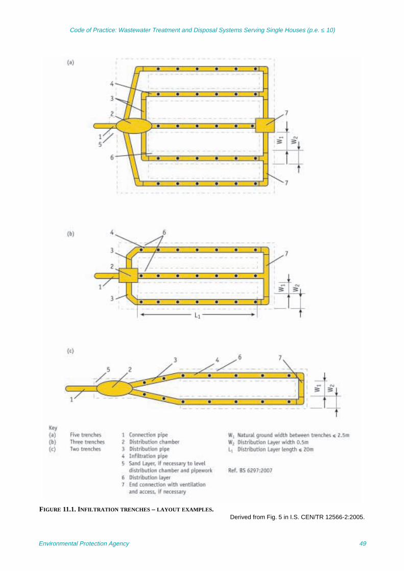
Code of Practice: Wastewater Treatment and Disposal Systems Serving Single Houses (p.e. ≤ 10)
FIGURE 11.1. INFILTRATION TRENCHES – LAYOUT EXAMPLES.Derived from Fig. 5 in I.S. CEN/TR 12566-2:2005.
Environmental Protection Agency 49

Code of Practice: Wastewater Treatment and Disposal Systems Serving Single Houses (p.e. ≤ 10)
comprise land drainage pipes overlain toground surface with permeable gravel orbroken stone aggregate. These interceptordrains are brought to the nearest watercourse
or stream into which they outfall. Constructionand installation should be supervised andcertified by a competent person and the workdocumented for future evidence.
Environmental Protection Agency 50

Code of Practice: Wastewater Treatment and Disposal Systems Serving Single Houses (p.e. ≤ 10)
12 Operation and Maintenance of Wastewater TreatmentSystems
12.1 Introduction
Appropriate site selection, choice of thetreatment system and the correct installationare critical steps to provide for the treatment ofdomestic effluent from a single house.Homeowners are ultimately responsible for theinstallation, operation and maintenance of theirwastewater treatment system. Section 70 ofthe Water Services Act, 2007 places a ‘duty ofcare’ on the owner of a wastewater treatmentsystem to ensure that it is kept so as not to“cause, or be likely to cause, a risk to humanhealth or the environment, including waters, theatmosphere, land, soil, plants or animals, orcreate a nuisance through odours. Anauthorised person appointed by a waterservices authority may direct the owner oroccupier to take such measures as areconsidered by the authorised person to benecessary to deal with the risk. Refusal tocomply with such a direction or obstruction ofthe authorised person is an offence.”
The onus is on the owner or builder to installsuitable wastewater treatment systemscorrectly and in accordance with themanufacturer’s instructions, planningpermission and any relevant conditionsattached thereto, building regulations and therecommendations set out in this code. Buildersshould provide information for the operationand maintenance of the system to the housepurchaser. All inspection and maintenancework should be carried out by competentpersons in accordance with the
recommendations herein, the manufacturer’sinstructions where available, relevant healthand safety legislation, waste disposallegislation, etc. The homeowner should bediscouraged from undertaking maintenance oraccessing the wastewater treatment systemitself for safety reasons.
The manner in which the treatment system ismaintained after it is installed is of equalimportance to ensure that the environment andhuman health are protected on an ongoingbasis after the house is occupied.
Septic tank treatment systems will require adifferent approach for proper maintenance thanpackaged treatment systems. Septic tanks donot normally require the use of mechanicalparts, electrical components or sensitiveequipment of the type that may be used in themore advanced systems unless the effluent isbeing pumped to an intermittent dosing system.Therefore, in the case of septic tank systems,visual inspection of the system on a periodicbasis as well as regular de-sludging is requiredto ensure that the system continues to operateeffectively. Guidance for the maintenance ofseptic tanks can therefore be seen as moreuniversally prescriptive and the approach takento the maintenance of all septic tanks will besimilar. In the case of packaged systems theoperation and maintenance of the system in allcases should be carried out in accordance withthe manufacturer’s instructions.
Filter systems (secondary and tertiarytreatment systems) require that the pumps anddistribution systems be adequately maintained.
Packaged treatment systems, which may beused for either secondary or tertiary treatment(such as RBCs, BAFs, SAFs, SBRs and MBRsystems), rely on the precise functioning ofmechanical and/or electrical components forproper operation. Apart from carrying outperiodic visual inspections of the system, therewill also be a requirement to repair, service or
Maintenance of all wastewater treatmentsystems is essential to ensure ongoingtreatment of wastewater. Homeowners shouldobtain the appropriate documentation includingmanufacturer’s instructions on the system fromthe builder/supplier and should take all steps toensure that their system is properly operatedand maintained.
Environmental Protection Agency 51
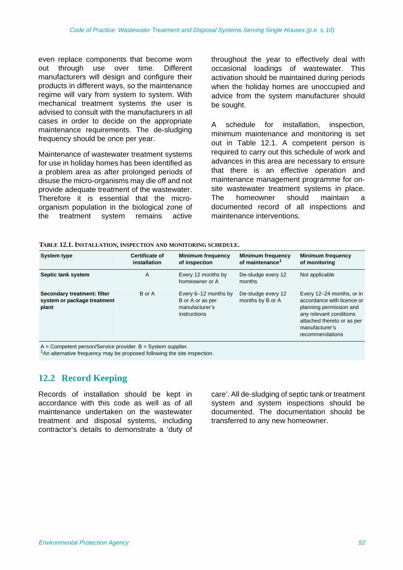
Code of Practice: Wastewater Treatment and Disposal Systems Serving Single Houses (p.e. ≤ 10)
even replace components that become wornout through use over time. Differentmanufacturers will design and configure theirproducts in different ways, so the maintenanceregime will vary from system to system. Withmechanical treatment systems the user isadvised to consult with the manufacturers in allcases in order to decide on the appropriatemaintenance requirements. The de-sludgingfrequency should be once per year.
Maintenance of wastewater treatment systemsfor use in holiday homes has been identified asa problem area as after prolonged periods ofdisuse the micro-organisms may die off and notprovide adequate treatment of the wastewater.Therefore it is essential that the micro-organism population in the biological zone ofthe treatment system remains active
throughout the year to effectively deal withoccasional loadings of wastewater. Thisactivation should be maintained during periodswhen the holiday homes are unoccupied andadvice from the system manufacturer shouldbe sought.
A schedule for installation, inspection,minimum maintenance and monitoring is setout in Table 12.1. A competent person isrequired to carry out this schedule of work andadvances in this area are necessary to ensurethat there is an effective operation andmaintenance management programme for on-site wastewater treatment systems in place.The homeowner should maintain adocumented record of all inspections andmaintenance interventions.
12.2 Record Keeping
Records of installation should be kept inaccordance with this code as well as of allmaintenance undertaken on the wastewatertreatment and disposal systems, includingcontractor’s details to demonstrate a ‘duty of
care’. All de-sludging of septic tank or treatmentsystem and system inspections should bedocumented. The documentation should betransferred to any new homeowner.
TABLE 12.1. INSTALLATION, INSPECTION AND MONITORING SCHEDULE.
System type Certificate of installation
Minimum frequencyof inspection
Minimum frequencyof maintenance1
Minimum frequencyof monitoring
Septic tank system A Every 12 months by homeowner or A
De-sludge every 12 months
Not applicable
Secondary treatment: filter system or package treatment plant
B or A Every 6–12 months by B or A or as per manufacturer’s instructions
De-sludge every 12 months by B or A
Every 12–24 months, or in accordance with licence or planning permission and any relevant conditions attached thereto or as per manufacturer’s recommendations
A = Competent person/Service provider. B = System supplier. 1An alternative frequency may be proposed following the site inspection.
Environmental Protection Agency 52

Code of Practice: Wastewater Treatment and Disposal Systems Serving Single Houses (p.e. ≤ 10)
PART TWO: GUIDANCEAnnex A Policy Background
A.1 General
The 2006 census indicated that around 40% ofthe population of Ireland lived outside of themain cities and towns with a population of1,500 and over. Unlike other, more urbanised,European countries, around a third of thepopulation of Ireland lives in the opencountryside in individual dwellings notconnected to a public sewer. The wastewaterfrom such rural settlement patterns is disposedof to systems of various types designed to treatthe wastewater at or near the location where itis produced. Ireland enjoys a high-qualityenvironment and the conservation andenhancement of our environment is a keyobjective for the future. It is correspondinglyvital that the protection of our environment andspecifically ground and surface water quality, isa central objective in the assessment, design,installation and maintenance of newwastewater disposal systems in un-seweredareas. This code of practice (CoP) establishesan overall framework of best practice inmeeting the above objective.
The Minister for the Environment publishedplanning guidelines under Section 28 of thePlanning and Development Act 2000 onSustainable Rural Housing in 2005. Theguidelines establish an overall national-levelpolicy framework for future housingdevelopment in rural areas, which has beenadopted into the majority of countydevelopment plans. In particular, the guidelineshighlight that those sites for new houses in un-sewered rural areas must be suitable for theinstallation and operation of on-site wastewatertreatment systems and take into account localground conditions. This CoP contains anassessment methodology for the determinationof whether or not a site is deemed suitable.
The Department of the Environment, Heritageand Local Government (DoEHLG) issued aCircular Letter (SP 5/03) to planning authorities
on 31 July 2003. This Circular drew theattention of planning authorities to the vitalimportance of sound development plan policiesrelating to the protection of surface andgroundwater quality, the importance of goodlocation and design of necessary developmentin rural areas, and the then current standardsfor on-site wastewater treatment systems.
The overall regulatory and policy framework atnational level is therefore clear on the need forthe application of high standards in theassessment of, provision and maintenance ofeffective on-site wastewater disposal systemsfor new housing developments in rural areasand this CoP presents comprehensiverecommendations for the attainment of suchhigh standards in line with the regulatory andpolicy frameworks.
A.2 Planning Authorities
Under Article 22(2)(c) of the Planning andDevelopment Regulations 2006, where it isproposed to dispose of wastewater other thanto a public sewer from a development proposedas part of a planning application to a planningauthority, the applicant must submit informationon the type of on-site treatment systemproposed and evidence as to the suitability ofthe site for the system proposed as part of thatplanning application.
Planning authorities therefore have a key rolein making decisions on the suitability of sites fordevelopment, and the assessment of thesuitability of particular sites for on-sitewastewater treatment and disposal systemswill be a key element of such decision-makingprocesses in un-sewered areas. This CoPprovides the methodology for undertaking suchsite suitability assessments in accordance withthe overall regulatory and policy framework setout by the DoEHLG relating to the planningsystem.
Environmental Protection Agency 53

Code of Practice: Wastewater Treatment and Disposal Systems Serving Single Houses (p.e. ≤ 10)
Assessment of site suitability under this CoPshould have regard to policies contained in thedevelopment plans as referred to above andany other relevant parallel documents such asgroundwater protection schemes (GWPSs)prepared by the Geological Survey of Ireland(GSI) and river basin management plansproduced under the Irish transposition of theEU Water Framework Directive.
Many on-site wastewater treatment systemsare available for single houses and aredesigned to:
• Treat the wastewater to minimisecontamination of soils and waterbodies
• Prevent direct discharge of untreatedwastewater to the groundwater or surfacewater
• Protect humans from contact withwastewater
• Keep animals, insects, and vermin fromcontact with wastewater, and
• Minimise the generation of foul odours.
Public health specifically and water quality ingeneral are threatened when on-site systemsfail to operate satisfactorily. System failurescan result in wastewater ponding or formingstagnant pools on the ground surface when thewastewater is not absorbed by the soil. In suchcircumstances of system failure, humans cancome in contact with the ponded wastewaterand be exposed to pathogens and also foulodours can be generated. Inadequately treatedwastewater through poor location, designand/or construction may lead to contaminationof our groundwater and surface waters, whichin many areas are also used as drinking watersupplies. In some cases, both the wastewatertreatment system and the private drinkingwater supply source are located on the onesite; therefore, it is essential that the effluent isproperly treated and disposed of. It is theresponsibility of the homeowner to ensure thatthe wastewater treatment system is installed inaccordance with the planning permission andany relevant conditions attached thereto, andthat it is properly maintained on a regular basis
to ensure that it does not cause pollution of theenvironment or of drinking waters.
A.3 Legislative Provisions
Wastewater treatment systems are designed todischarge treated effluent to waters; in Irelandmost of the small-scale on-site systemsdischarge to ground via percolation through thesoil and subsoil. In all cases, the requirementsof the water protection legislation shall becomplied with. The main water protectionlegislation includes:
• Water Services Act, 2007 (S.I. No. 30 of2007)
• Local Government (Water Pollution) Act,1977 (S.I. No. 1 of 1977).
• Local Government (Water Pollution)(Amendment) Act, 1990 (S.I. No. 21 of1990)
• Local Government (Water Pollution) Act,1997 (Water Quality Standard forPhosphorus) Regulations, 1998 (S.I. No.258 of 1998)
• Local Government (Water Pollution)Regulations, 1978 (S.I. No. 108 of 1978)
• Local Government (Water Pollution)Regulations, 1992 (S.I. No. 271 of 1992)
• Local Government (Water Pollution)(Amendment) Regulations, 1996 (S.I. No.184 of 1996)
• Local Government (Water Pollution)(Amendment) Regulations, 1999 (S.I. No.42 of 1999)
• Protection of Groundwater Regulations,1999 (S.I. No. 41 of 1999)
• Fisheries (Consolidation) Act (Amendment)1959.
In addition, the following European legalisationprovides protection to groundwater:
• Council Directive on the protection ofgroundwater against pollution caused bycertain dangerous substances (80/68/EEC)
Environmental Protection Agency 54

Code of Practice: Wastewater Treatment and Disposal Systems Serving Single Houses (p.e. ≤ 10)
• Council Directive concerning the protectionof waters against pollution caused bynitrates from agricultural sources(91/676/EEC)
• Directive 2000/60/EC of the EuropeanParliament and Council establishing aframework for Community action in the fieldof water policy (2000/60/EC) (commonlyreferred to as the Water FrameworkDirective), and
• Directive 2006/118/EC of the EuropeanParliament and Council on the protection ofgroundwater against pollution anddeterioration (2006/118/EC).
At European level, work is being completed onthe development of the EN 12566 series ofstandards for Small Wastewater TreatmentSystems for up to 50 PT. The EN 12566 seriesof standards is developed and published byComité Européen de Normalisation (EuropeanCommittee for Standardisation) (CEN) andadopted by the National Standards Authority ofIreland (NSAI). Their content has been takeninto account in the preparation of thisdocument.
I.S. EN 12566-1:2000/A1:2004, I.S. EN 12566-3:2005 and I.S. EN 12566-4:2007 areconstruction product standards within the termsof the Construction Products Directive and, assuch, any requirements regarding thespecification and performance of productscovered by these standards and referenced inAnnex ZA of the standard, must be based onthe content of the standard and the tests andprocedures defined in the standards. prEN12566-6 and prEN 12566-7, when adopted, willalso be construction product standards andsimilar considerations will apply.
The CoP cross-references the appropriatesections of the standard; however, the reader isreferred to the individual parts of thestandards/technical reports for full details. Thestatus of the individual parts is listed below:
• I.S. EN 12566-1:2000/A1:2004 SmallWastewater Treatment Systems for up to 50PT – Part 1: Prefabricated Septic Tanks(published by the NSAI as an IrishStandard)
• I.S. CEN/TR 12566-2:2005 SmallWastewater Treatment Systems for up to 50PT – Part 2: Soil Infiltration Systems(published by the NSAI as a Code ofPractice)
• I.S. EN 12566-3:2005 Small WastewaterTreatment Systems for up to 50 PT – Part 3:Packaged and/or Site Assembled DomesticWastewater Treatment Plants (published bythe NSAI as an Irish Standard)
• I.S. EN 12566-4:2007 Small WastewaterTreatment Systems for up to 50 PT – Part 4:Septic Tanks Assembled in situ fromPrefabricated Kits (published by CEN)
• I.S. CEN/TR12566-5:2008 Small Wastewater Treatment Systems for up to 50 PT –Part 5: Pre-Treated Effluent FiltrationSystems (published by CEN as a technicalreport)
• prEN 12566-6 Small Wastewater TreatmentSystems for up to 50 PT – Part 6:Prefabricated Treatment Units for SepticTank Effluent (in preparation)
• prEN 12566-7 Small Wastewater TreatmentSystems for up to 50 PT – Part 7:Prefabricated Tertiary Treatment Units (inpreparation).
Some of these standards apply to (or will applyto) products that are deemed to be constructionproducts for the purposes of the ConstructionProducts Directive and are know asharmonised European Standards (hENs), e.g.I.S. EN 12566-1:2000/A1:2004, I.S. EN 12566-3:2005 and I.S. EN 12566-4:2007, etc. At theend of a set co-existence period, existingconflicting national standards must bewithdrawn and all relevant products beingplaced on the market should comply with theharmonised parts of the standard and meet theperformance requirement as set out in PartOne of this CoP. The coexistence period forharmonised European Standards can be foundon the European Commissions NANDOdatabase (http://ec.europa.eu/enterprise/newapproach/nando/).
In the case of a hEN not yet being available,products should be certified (certification may
Environmental Protection Agency 55
Code of Practice: Wastewater Treatment and Disposal Systems Serving Single Houses (p.e. ≤ 10)
include a European Technical Approval, anAgrément Certificate or equivalent), be fit forthe purpose for which they are intended, theconditions in which they are used and meet theperformance requirements as set out in PartOne of this CoP.
The DoEHLG issued a Circular Letter(BC16/2006) in November 2006 providinginterim advice to local authorities in relation toEuropean Standards for domestic wastewatertreatment plants. It advises that I.S. EN 12566-3:2005 has been adopted by CEN andtransposed in Ireland by the NSAI as I.S. EN12566-3:2005. Wastewater treatment plantsare deemed to be construction products for thepurposes of the Construction Products
Directive (89/106/EEC) and the requirementsof that directive apply to these systems. It alsoindicates that the Second Edition of theEnvironmental Protection Agency (EPA)Wastewater Treatment Manual: TreatmentSystems for Single Houses (now the Code ofPractice: Wastewater Treatment and DisposalSystems Serving Single Houses) will provideguidance on performance levels that can begenerally applied; in their absence it refers tothe wastewater treatment performancestandards of the Irish Agrément Board (IAB).They are biochemical oxygen demand – 20mg/l, suspended solids – 30 mg/l, andammonia as NH4 – 20 mg/l.
Environmental Protection Agency 56

Code of Practice: Wastewater Treatment and Disposal Systems Serving Single Houses (p.e. ≤ 10)
Annex B Groundwater Protection Response
B.1 Background
The primary responsibility for groundwaterprotection rests with any person who is carryingon an activity that poses a threat togroundwater. Groundwater in Ireland isprotected under European Community andnational legislation. Local authorities and theEnvironmental Protection Agency (EPA) haveresponsibility for enforcing this legislation. In1999, the GSI, in conjunction with theDepartment of Environment and LocalGovernment (DoELG) and the EPA, issuedguidelines on the preparation of GWPSs toassist the statutory authorities and others tomeet their responsibility to protect groundwater(DoELG/EPA/GSI, 1999a,b). A GWPSincorporates land surface zoning andgroundwater protection responses (GWPRs).
This document is concerned with GWPRs forthe siting of on-site wastewater treatmentsystems for a dwelling house of up to 10 peoplewith facilities for toilet usage, living, sleeping,bathing, cooking and eating. The GWPRsoutline acceptable on-site wastewatertreatment systems in each groundwaterprotection zone (DoELG/EPA/GSI, 2001) andrecommend conditions and/or investigationsdepending on the groundwater vulnerability,the value of the groundwater resource and thecontaminant loading. It should be noted thatthese responses update the responses issuedin 2001 and relate to discharges from singlehouses to groundwater. Less stringentresponses may be appropriate for dischargesto surface waters.
In Ireland, wastewater from approximately400,000 dwellings is treated by on-sitesystems. On-site systems can be subdividedinto two broad categories: septic tank systemsand mechanical aeration systems.
A septic tank system consists of a septic tankfollowed by a soil percolation area. As analternative to a percolation area the effluent
from a septic tank can be treated by filtersystems such as:
• A soil percolation system in the form of amound
• An intermittent sand filter followed by apolishing filter
• An intermittent peat filter followed by apolishing filter
• An intermittent plastic or other media filterfollowed by a polishing filter, or
• A constructed wetland or reed bed, followedby a polishing filter.
Mechanical aeration systems include biofilmaerated (BAF) systems, rotating biologicalcontactor (RBC) systems, and sequencingbatch reactor (SBR) systems. The effluent froma mechanical aeration system should betreated by a polishing filter to reduce micro-organisms, and in some soil conditionsphosphorus. On-site wastewater systems arethe primary method used for the treatment anddisposal of domestic wastewater in rural areas.These systems are also used in urban areas,which are not connected to public sewersystems. On-site domestic wastewatertreatment systems are often located close toprivate or public wells.
When choosing the location and type of on-sitesystem, builders should have regard to anynearby groundwater source, the groundwateras a resource and the vulnerability of theunderlying groundwater. The GWPRs in thisguidance combine these factors to produce aresponse matrix.
The objectives of these GWPRs are:
• To reduce the risk of pollutants reachingdrinking water supplies
• To reduce the risk of pollution of aquifers
• To minimise pollution of domestic wells, and
Environmental Protection Agency 57
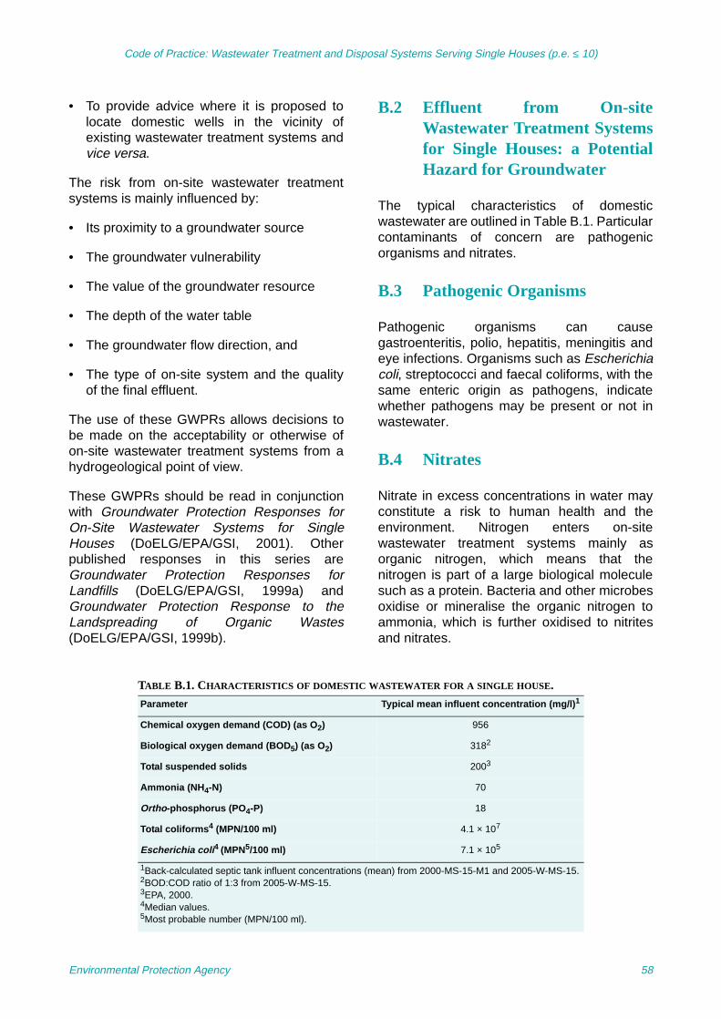
Code of Practice: Wastewater Treatment and Disposal Systems Serving Single Houses (p.e. ≤ 10)
• To provide advice where it is proposed tolocate domestic wells in the vicinity ofexisting wastewater treatment systems andvice versa.
The risk from on-site wastewater treatmentsystems is mainly influenced by:
• Its proximity to a groundwater source
• The groundwater vulnerability
• The value of the groundwater resource
• The depth of the water table
• The groundwater flow direction, and
• The type of on-site system and the qualityof the final effluent.
The use of these GWPRs allows decisions tobe made on the acceptability or otherwise ofon-site wastewater treatment systems from ahydrogeological point of view.
These GWPRs should be read in conjunctionwith Groundwater Protection Responses forOn-Site Wastewater Systems for SingleHouses (DoELG/EPA/GSI, 2001). Otherpublished responses in this series areGroundwater Protection Responses forLandfills (DoELG/EPA/GSI, 1999a) andGroundwater Protection Response to theLandspreading of Organic Wastes(DoELG/EPA/GSI, 1999b).
B.2 Effluent from On-siteWastewater Treatment Systemsfor Single Houses: a PotentialHazard for Groundwater
The typical characteristics of domesticwastewater are outlined in Table B.1. Particularcontaminants of concern are pathogenicorganisms and nitrates.
B.3 Pathogenic Organisms
Pathogenic organisms can causegastroenteritis, polio, hepatitis, meningitis andeye infections. Organisms such as Escherichiacoli, streptococci and faecal coliforms, with thesame enteric origin as pathogens, indicatewhether pathogens may be present or not inwastewater.
B.4 Nitrates
Nitrate in excess concentrations in water mayconstitute a risk to human health and theenvironment. Nitrogen enters on-sitewastewater treatment systems mainly asorganic nitrogen, which means that thenitrogen is part of a large biological moleculesuch as a protein. Bacteria and other microbesoxidise or mineralise the organic nitrogen toammonia, which is further oxidised to nitritesand nitrates.
TABLE B.1. CHARACTERISTICS OF DOMESTIC WASTEWATER FOR A SINGLE HOUSE.
Parameter Typical mean influent concentration (mg/l)1
Chemical oxygen demand (COD) (as O2) 956
Biological oxygen demand (BOD5) (as O2) 3182
Total suspended solids 2003
Ammonia (NH4-N) 70
Ortho-phosphorus (PO4-P) 18
Total coliforms4 (MPN/100 ml) 4.1 × 10⁷
Escherichia coli4 (MPN5/100 ml) 7.1 × 10⁵
1Back-calculated septic tank influent concentrations (mean) from 2000-MS-15-M1 and 2005-W-MS-15.2BOD:COD ratio of 1:3 from 2005-W-MS-15.3EPA, 2000.4Median values.5Most probable number (MPN/100 ml).
Environmental Protection Agency 58

Code of Practice: Wastewater Treatment and Disposal Systems Serving Single Houses (p.e. ≤ 10)
B.5 Groundwater ProtectionResponse Matrix for SingleHouse Systems
The reader is referred to the full text inGroundwater Protection Responses for On-Site Systems for Single Houses(DoELG/EPA/GSI, 2001) for an explanation ofthe role of GWPRs in a GWPS.
A risk assessment approach is taken in thedevelopment of this response matrix. Aprecautionary approach is taken because ofthe variability of Irish subsoils, bedrock and thepossibility that the treatment system may notfunction properly at all times. Where there is ahigh density of dwellings in the vicinity of public,group scheme or industrial water supplysources, more restrictive conditions may berequired or the development may need to berefused. The density of dwellings andassociated treatment systems may impact onthe groundwater because of the cumulativeloading, particularly of nitrate. This should betaken into account especially where thevulnerability of the groundwater is high orextreme.
The potential suitability of a site for thedevelopment of an on-site system is assessedusing the methodology outlined in Section 6.The methodology includes a desk study andon-site assessment (visual, trial hole test andpercolation tests). The GWPRs set out in TableB.2 should be used during the desk study
assessment of a site to give an early indicationof the suitability of a site for an on-site system.Information from the on-site assessmentshould be used to confirm or modify theresponse. In some situations, site improvementworks, followed by reassessment of thegroundwater responses, may allow a system tobe developed. Site improvements are dealtwith in Section 6.5.
Where groundwater protection zones have notyet been delineated for an area, the responsesbelow should be used in the followingcircumstances:
• Where on-site systems are proposed in thevicinity of domestic wells
• Where on-site systems are proposed in thevicinity of sources of water with anabstraction rate above 10 m3/day (e.g.public, group scheme and industrial supplywells and springs)
• Where groundwater is extremely vulnerable(based on the visual assessment and trialhole test), and
• Where there are karst features such asswallow holes, caves, etc.
The appropriate response to the risk ofgroundwater contamination from an on-sitewastewater treatment system is given by theassigned response category (R) appropriate toeach protection zone.
TABLE B.2. RESPONSE MATRIX FOR ON-SITE TREATMENT SYSTEMS.
Vulnerability rating Source protectionArea1
Resource protection areaAquifer category
Regionally improved Locally improved Poor aquifers
Inner (SI) Outer (SO) Rk Rf/Rg Lm/Lg Ll Pl Pu
Extreme (E) R32 R31 R22 R22 R21 R21 R21 R21
High (H) R24 R23 R21 R1 R1 R1 R1 R1
Moderate (M) R24 R23 R1 R1 R1 R1 R1 R1
Low (L) R24 R1 R1 R1 R1 R1 R1 R1
1For public, group scheme or industrial water supply sources where protection zones have not been delineated, the arbitrary distancesgiven in DoELG/EPA/GSI (1999a,b) of 300 m for the Inner Protection Area (SI) and 1,000 m for the Outer Protection Area (SO) shouldbe used as a guide up-gradient of the source.Rk, Regionally Important Karstified Aquifers; Rf, Regionally Important Fissured Bedrock Aquifers; Rg, Regionally Important ExtensiveSand and Gravel Aquifers; Lg, Locally Important Sand/Gravel Aquifers; Lm, Locally Important – Bedrock Aquifer which is generallymoderately productive; Ll, Locally Important – Bedrock Aquifer which is moderately productive in local zones; Pl, Poor – BedrockAquifer which is generally unproductive except for local zones; Pu, Poor – Bedrock Aquifer which is generally unproductive.
Environmental Protection Agency 59

Code of Practice: Wastewater Treatment and Disposal Systems Serving Single Houses (p.e. ≤ 10)
R1 Acceptable subject to normal good practice(i.e. system selection, construction,operation and maintenance in accordancewith this CoP).
R21 Acceptable subject to normal goodpractice. Where domestic water suppliesare located nearby, particular attentionshould be given to the depth of subsoil overbedrock such that the minimum depthsrequired in Section 6 are met and that thelikelihood of microbial pollution isminimised.
R22 Acceptable subject to normal good practiceand the following additional condition:
1. There is a minimum thickness of 2 munsaturated soil/subsoil beneath theinvert of the percolation trench of aseptic tank system
or
1. A secondary treatment system asdescribed in Sections 8 and 9 isinstalled, with a minimum thickness of0.3 m unsaturated soil/subsoil with P/T-values from 3 to 75 (in addition to thepolishing filter which should be aminimum depth of 0.9 m), beneath theinvert of the polishing filter (i.e. 1.2 m intotal for a soil polishing filter).
R23 Acceptable subject to normal goodpractice, Condition 1 above and thefollowing additional condition:
2. The authority should be satisfied that,on the evidence of the groundwaterquality of the source and the number ofexisting houses, the accumulation ofsignificant nitrate and/or microbiologicalcontamination is unlikely.
R24 Acceptable subject to normal goodpractice, Conditions 1 and 2 above and thefollowing additional condition:
3. No on-site treatment system should belocated within 60 m of a public, groupscheme or industrial water supplysource.
R31 Not generally acceptable, unless:
A septic tank system as described inSection 7 is installed with a minimumthickness of 2 m unsaturated soil/subsoilbeneath the invert of the percolation trench(i.e. an increase of 0.8 m from therequirements in Section 6)
or
A secondary treatment system, asdescribed in Sections 8 and 9, is installed,with a minimum thickness of 0.3 munsaturated soil/subsoil with P/T-valuesfrom 3 to 75 (in addition to the polishingfilter which should be a minimum depth of0.9 m), beneath the invert of the polishingfilter (i.e. 1.2 m in total for a soil polishingfilter)
and subject to the following conditions:
1. The authority should be satisfied that,on the evidence of the groundwaterquality of the source and the number ofexisting houses, the accumulation ofsignificant nitrate and/or microbiologicalcontamination is unlikely
2. No on-site treatment system should belocated within 60 m of a public, groupscheme or industrial water supplysource
3. A management and maintenanceagreement is completed with thesystems supplier.
R32 Not generally acceptable unless:
A secondary treatment system is installed,with a minimum thickness of 0.9 munsaturated soil/subsoil with P/T-valuesfrom 3 to 75 (in addition to the polishingfilter which should be a minimum depth of0.9 m), beneath the invert of the polishingfilter (i.e. 1.8 m in total for a soil polishingfilter)
and subject to the following conditions:
1. The authority should be satisfied that,on the evidence of the groundwaterquality of the source and the number ofexisting houses, the accumulation ofsignificant nitrate and/or microbiologicalcontamination is unlikely
2. No on-site treatment system should be
Environmental Protection Agency 60

Code of Practice: Wastewater Treatment and Disposal Systems Serving Single Houses (p.e. ≤ 10)
located within 60 m of a public, groupscheme or industrial water supplysource
3. A management and maintenanceagreement is completed with thesystems supplier.
The responses above assume that there is nosignificant groundwater contamination in thearea. Should contamination by pathogenicorganisms or nitrate (or other contaminants) bea problem in any particular area, morerestrictive responses may be necessary.Where nitrate levels are known to be high ornitrate-loading analysis indicates a potentialproblem, consideration should be given to theuse of treatment systems, which include a de-nitrification unit. Monitoring carried out by thelocal authority will assist in determiningwhether or not a variation in any of theseresponses is required.
Sites are not suitable for discharge of effluent toground for very low permeability subsoils(where T > 90).
B.6 Additional Requirements forthe Location of On-SiteTreatment Systems Adjacent toReceptors at Risk, such asWells and Karst Features
Table B.2 outlines responses for differenthydrogeological situations, which may restrictthe type of on-site treatment system, andshould be satisfied in the first instance. Once aresponse has been determined for a site, thenext step is to manage the risk posed to thefeatures identified during the desk study andon-site assessment. These features includewater supply wells and springs (public anddomestic), and karst features that enable thesoils and subsoil to be bypassed (e.g. swallowholes, collapse features).
Table B.3 provides recommended distancesbetween receptors (see also Fig. B.1) andpercolation area or polishing filters, in order toprotect groundwater. These distances dependon the thickness and permeability of subsoil.The depths and distances given in this table are
FIGURE B.1. RELATIVE LOCATION OF WELLS.
Environmental Protection Agency 61

Code of Practice: Wastewater Treatment and Disposal Systems Serving Single Houses (p.e. ≤ 10)
based on the concepts of ‘risk assessment’ and‘risk management’, and take account, as far aspracticable, of the uncertainties associated withhydrogeological conditions in Ireland. Use ofthe depths and distances in this table does notguarantee that pollution will not be caused;rather, it will reduce the risk of significantpollution occurring.
Where an on-site system is in the zone ofcontribution of a well, the likelihood ofcontamination and the threat to human healthdepend largely on five factors:
1. The thickness and permeability of subsoilbeneath the invert of the percolation trench
2. The permeability of the bedrock, where thewell is tapping the bedrock
3. The distance between the well or springand the on-site system
4. The groundwater flow direction, and
5. The level of treatment of effluent.
TABLE B.3. RECOMMENDED MINIMUM DISTANCE BETWEEN A RECEPTOR AND A PERCOLATION AREA OR POLISHING
FILTER.T/P-value1 Type of soil/subsoil2 Depth of
soil/subsoil(m above bedrock)
(see Notes 1, 2, 3, 6)
Minimum distance (m) from receptor to percolation area or polishing filter5
Public water
supply
Karst feature
Down-gradient domestic well orflow direction is
unknown(see Note 5)
Domestic wellalongside
(no gradient)
Up-gradient domestic well
>30CLAY; sandyCLAY (e.g. clayey till); SILT/CLAY
1.2>3.0 60 15
4030 25 15
10–30Sandy SILT; siltySAND; silty GRAVEL (e.g. sandy till)
1.2>8.0 60 15
4530 25 15
<10 SAND; GRAVEL; silty SAND
2.03
2.04
>8.0460 15
604030
25 15
1The T-value (expressed as min/25 mm) is the time taken for the water level to drop a specified distance in a percolation test hole. Forshallow subsoils the test hole requirements are different and hence the test results are called P-values. For further advice see AnnexC.
2BS 5930 descriptions. 3Water table 1.2–2.0 m. 4Water table >2.0 m.5The distance from the percolation area or polishing filter means the distance from the periphery of the percolation area or polishingfilter and not from the centre.
Notes: 1. Depths are measured from the invert level of the percolation trench.
2. Depths and distances can be related by interpolation: e.g. where the thickness of sandy CLAY is 1.2 m, the minimumrecommended distance from the well to percolation area is 40 m; where the thickness is 3.0 m, the distance is 30 m; distances forintermediate depths can be approximated by interpolation.
3. Where bedrock is shallow (<2 m below invert of the trench), greater distances may be necessary where there is evidence of thepresence of preferential flow paths (e.g. cracks, roots) in the subsoil.
4. Where the minimum subsoil thicknesses are less than those given above, site improvements and systems other than systems asdescribed in Sections 8 and 9 may be used to reduce the likelihood of contamination.
5. If effluent and bacteria enter bedrock rapidly (within 1–2 days), the distances given may not be adequate where the percolationarea is in the zone of contribution of a well. Further site-specific evaluation is necessary.
6. Where bedrock is known to be karstified or highly fractured, greater depths of subsoil may be advisable to minimise the likelihoodof contamination.
Environmental Protection Agency 62

Code of Practice: Wastewater Treatment and Disposal Systems Serving Single Houses (p.e. ≤ 10)
Annex C Site Characterisation
The key to installing a reliable on-site systemthat minimises the potential for pollution is toselect and design a suitable treatment systemfollowing a thorough site assessment. For asubsoil to be effective as a medium for treatingwastewater, it should be permeable enough toallow throughflow and remain unsaturated,whilst capable of retaining the wastewater for asufficient length of time to allow attenuation inthe aerobic conditions.
Only after a site assessment has beencompleted can an on-site system be chosen ifthe site has been deemed suitable. Theinformation collected in the evaluation will beused to select the on-site system. The followingsections elaborate on the requirements set outin Section 6 of the code. The relevant sectionsof the Site Characterisation Form should becompleted in all cases.
C.1 Desk Study
The purposes of the desk study are to:
• Obtain existing information relevant to thesite, which will assist in assessing itssuitability
• Identify targets at risk, and
• Establish if there are restrictions relating tothe site.
A desk study involves the assessment ofavailable data pertaining to the site andadjoining areas that may determine whetherthe site has any restrictions. Informationcollected from the desk study should includeany material related to the hydrological,hydrogeological and planning aspects of thesite that may be available. The density ofexisting housing and performance of theexisting wastewater treatment systems willaffect existing groundwater quality and shouldbe noted at this stage. In addition, the locationof any archaeological or natural heritage sites(Special Area of Conservation (SAC), SpecialProtection Area (SPA), etc.) in the vicinity of the
proposed site should be identified. The LocalDevelopment Plan and planning register cancontain a wide range of planning andenvironmental information. The local authorityheritage officer should also be consulted todetermine the significance of anyarchaeological sites located in the vicinity.
The GWPSs provide guidelines for builders inassessing groundwater resources andvulnerability and for planning authorities incarrying out their groundwater protectionfunctions. They provide a framework to assist indecision making on the location, nature andcontrol of developments and activities(including single-house treatment systems) inorder to protect groundwater. GWPR zoningoutlines the aquifer classification in the generalarea and the vulnerability of the groundwater.The GWPRs will provide an early indication ofthe probable suitability of a site for an on-sitesystem. The on-site assessment will laterconfirm or modify such responses. The densityof on-site systems is also considered at thisstage. The protection responses required toprotect groundwater from on-site systemsshould be satisfied. Where no GWPS exists,interim measures, as set out in theGroundwater Protection Schemes should beadopted. If additional requirements arerequired then this should be noted in thecomments section. Also, if there are existing orproposed wells in the area then the minimumdistances set out in the GWPRs should benoted at this stage. Note, if the GWPR is R23 orhigher, the groundwater quality needs to beassessed.
C.2 On-site Assessment
C.2.1 Visual assessmentThe factors examined during a visualassessment and their significance aresummarised in Table C.1. The principal factorsthat should be considered are as follows:
Landscape position: Landscape positionreflects the location of the site in the landscape,
Environmental Protection Agency 63

Code of Practice: Wastewater Treatment and Disposal Systems Serving Single Houses (p.e. ≤ 10)
e.g. crest of hill, valley, slope of hill. Sites thatare on level, well-drained areas, or on convexslopes are most desirable. Sites that are indepressions, or on the bottom of slopes or onconcave slopes are less desirable and may beunsuitable.
Slope: It is more difficult to install pipework andensure that the wastewater will stay in the soilif the land has a steep slope. In some cases thepipes should be laid along the contours of theslope. Where there is surface water run-off andinterflow, low-lying areas and flat areasgenerally receive more water. This accounts tosome extent for the occurrence of poorlydrained soils in low-lying areas. Soils with poordrainage, however, may also be found on goodslopes where the parent material or the subsoilis of low permeability. Provision should bemade for the interception of all surface run-offand seepage, and its diversion away from theproposed percolation area. Mound filtersystems are prohibited on sites where thenatural slope is greater than 1:8 (12%) as this
will lead to hydraulic overloading at the toe ofthe mound down slope.
Proximity to surface features: Minimumseparation distances, as set out in the followingsections should be maintained from specifiedfeatures. The presence/location of surfacefeatures such as watercourses, includingecologically sensitive receiving waters, siteboundaries, roads, steep slopes, etc., shouldbe noted. Minimum separation distances areset out in Table 6.1. Note, distances from lakesor rivers should be measured from the highwater level or flood water level.
Existing dwellings and wastewatertreatment systems: The performance ofexisting wastewater treatment and storm waterdisposal systems should be examined and thecause of problems identified and brought to theattention of the local authority to addressremediation. Potential impacts from adjacentwastewater treatment systems should also beconsidered.
TABLE C.1. FACTORS TO BE CONSIDERED DURING VISUAL ASSESSMENT.
Factor Significance
Water level in ditches and wells Indicates depth of unsaturated subsoil available for treatment or polishing of wastewater
Landscape position May indicate whether water will collect at a site or flow away from the site
Slope Pipework, surface water run-off and seepage. Influences the design of the system
Presence of watercourses, surface water ponding
May indicate low permeability subsoil or a high water table
Presence and types of bedrock outcrops Insufficient depth of subsoil to treat wastewater allowing it to enter the groundwater too fast
Proximity to existing adjacent percolation areas and/or density of houses
May indicate a high nutrient-loading rate for the locality and/or potential nuisance problems. The location of storm water disposal areas from adjacent houses also needs to be assessed with regard to its impact on the proposed percolation area
Land use and type of grassland surface (if applicable)
Suggests rate of percolation or groundwater levels
Vegetation indicators Suggest the rate of percolation or groundwater levels. The presence of indicator plants should not be taken as conclusive evidence that the site is suitable for a drainage system, but they might indicate where any subsequent soil investigations could take place
Proximity to wells on-site and off-site, water supply sources, groundwater, streams, ditches, lakes, surface water ponding, beaches, shellfish areas, springs, karst features, wetlands, flood plains and heritage features
Indicates targets at risk
Environmental Protection Agency 64

Code of Practice: Wastewater Treatment and Disposal Systems Serving Single Houses (p.e. ≤ 10)
In addition, the implication of any potentialimpact due to the increased nutrient load on thegroundwater quality in the area should beassessed. This is particularly true in areas ofhigh-density housing (iPlan system) and inareas where the background nitrateconcentrations are already elevated. It isestimated that a 6 p.e. wastewater treatmentsystem (without specially designed nutrientremoval) will increase the nitrate levels by 21mg/l NO3 per hectare6.
Wells/Springs: Wells should be considered astargets at risk. The number of wells and thepresence of any springs should be noted. Theminimum distances of wells/springs fromwastewater treatment systems and percolationareas/polishing filters are set out in the GWPRfor wastewater treatment systems for singlehouses (Annex B). Wastewater treatmentsystems do not pose a risk to decommissionedwells if the wells have been properly sealed offin accordance with BS 5930 or other guidancedocument.
Groundwater flow direction: In general,groundwater flow direction can be inferred fromtopography on sloping sites and/or proximity tosurface water features such as rivers or lakes.It should be indicated on the site plan.
Outcrops and karst features: The presenceof vulnerable features such as outcrops,swallow holes, etc., should be determined andthe distance between them and the proposeddevelopment noted.
Drainage: A high density of streams or ditchestends to indicate a high water table andpotential risk to surface water. Low streamdensity indicates a free-draining subsoil and/orbedrock.
Land use: Current and previous land useshould be noted, in particular any previousdevelopment on the site should be highlightedsuch as old building foundations, etc. Housingdensity should also be noted.
Vegetation indicators: Rushes, yellow flags(irises), alders and willow suggest poor
percolation characteristics or high water tablelevels. Grasses, trees and ferns may suggestsuitable percolation characteristics. Plants andtrees suggest good drainage and poordrainage are illustrated in Fig. C.1.
Ground conditions: The ground conditionsduring the on-site investigation should benoted. Trampling damage by livestock canindicate impeded drainage or intermittent highwater tables, especially where accompanied bywidespread ponding in hoof prints. Evidence ofinfill material or made ground should also benoted which may indicate the presence of soilswith poor percolation properties beneath.
Minimum separation distances: Theminimum separation distances, as set out inSection 6 – Table 6.1, should be checked atthis stage of the assessment.
C.2.1.1 Plants indicative of drainage conditionsFigure C.1 illustrates plants that indicate dryconditions (good drainage) and others thatindicate wet conditions (poor drainage)throughout the year. Some of the photosillustrate the plants in flower – this aspectshould be ignored. Plants in flower, orotherwise, do not change their indicator status.Note that alder is a tree.
C.2.2 Trial hole assessmentThe trial hole should be located adjacent to butnot within the proposed percolation area/polishing filter, as the disturbed subsoil willprovide a preferential flow path in the finalpercolation area.
The trial hole should remain open for aminimum period of 48 h to allow the water table(if present) to re-establish itself and be securelyfenced off and covered over to prevent theingress of surface water or rainwater. If on asloping site then a small drainage channelshould be dug on the up-slope side of the holeto prevent any surface water inflow into the trialhole.
The health and safety7 aspects of placing a trialhole on the site should be borne in mind. A trialhole is a deep, steep-sided excavation, whichmay contain water and which may be difficult toexit from if improperly constructed. A risk ofcollapse of the side walls of the trial hole may
6. Section 13.2.14 Site Suitability Assessments for On-SiteWastewater Management, FÁS Course Manual, Vol. 2.
Environmental Protection Agency 65

Code of Practice: Wastewater Treatment and Disposal Systems Serving Single Houses (p.e. ≤ 10)
FIGURE C.1. INDICATOR PLANTS OF DRY AND WET CONDITIONS.
Thistle Bracken Ragwort
Alder Iris
Rush Willow
Dry conditions
Wet conditions
Environmental Protection Agency 66

Code of Practice: Wastewater Treatment and Disposal Systems Serving Single Houses (p.e. ≤ 10)
exist in some situations. All appropriate healthand safety precautions should be taken. Thedepth of the percolation test hole is dependenton the subsoil characteristics present in the trialhole.
The soil and subsoil characteristics should bedetermined as per the code and the guidancebelow and documented in the SiteCharacterisation Form.
The observations made from the trial hole andtheir significance are summarised in Table C.2.
Depth to bedrock and depth to water table:For septic tank systems a depth of 1.2 m ofsuitable free-draining unsaturated subsoil, tothe bedrock and to the water table below thebase of the percolation trenches, should existat all times to ensure satisfactory treatment ofthe wastewater. In the case of secondarytreatment systems a minimum of 0.9 munsaturated subsoil is required. Sites assessedin summer when the water table is low, shouldbe examined below the proposed invert of thepercolation pipe for soil mottling (Fig. C.2) –- anindicator of seasonally high water tables. Forfurther details see the Groundwater NewsletterNo. 45 issued by the GSI (Daly, 2006).
Soil texture: Texture is the relative proportionsof sand, silt and clay particles in a soil. Therelative proportions of these constituents aredetermined using the British Standard
BS 5930:1999 Code of practice for siteinvestigations. The rate and extent of manyimportant physical processes and chemicalreactions in soils are governed by texture.Physical processes influenced by textureinclude drainage and moisture retention,diffusion of gases and the rate of transport ofcontaminants. Texture influences the biofilmsurface area in which biochemical andchemical reactions occur. The soil textureshould be characterised using the BS 5930classification. Every significant layer
7. Trial holes fall under the definition of construction work andall activities associated with them are subject to the Safety,Health and Welfare at Work (Construction) Regulations2001 and amendments. Further information can be obtainedfrom the Health and Safety Authority, 10 Hogan Place,Dublin 2.
TABLE C.2. FACTORS TO BE CONSIDERED DURING A TRIAL HOLE EXAMINATION.
Factors Significance
Soil/subsoil structure and texture Both influence the capacity of soil/subsoil to treat and dispose of the wastewater; subsoils with high clay content are generally unsuitable
Mottling (Fig. C.2) Indicates seasonal high water tables or very low permeability subsoil
Depth to bedrock Subsoil should be of sufficient depth to treat wastewater
Depth to water table Saturated subsoils do not allow adequate treatment of wastewater
Water ingress along walls Indicates high water table or saturated layers (e.g. perched water table)
Season Water table varies between seasons (generally high in winter)
FIGURE C.2. CLOSE-UP OF MOTTLING IN TRIAL HOLE.
Environmental Protection Agency 67

Code of Practice: Wastewater Treatment and Disposal Systems Serving Single Houses (p.e. ≤ 10)
encountered in the trial hole should bedescribed in the Site Characterisation Form.
A guide to assist the classification ofsoils/subsoils is included in Annex C.2.2.1.Various soil/subsoil texture classificationschemes exist. Table C.3 indicates sometypical percolation rates for different subsoiltypes but it is important to realise that thesecondary constituents of the subsoil may havean effect on the percolation test results, as willstructure and compactness.
Structure: Soil structure refers to thearrangement of the soil particles into largerunits or compound particles in the soil. The soilparticles, sand, silt, clay and organic matter,are generally clumped together to form largerunits called peds. The shape and size of thepeds can have a significant effect on thebehaviour of soils. A ped is a unit of soilstructure such as an aggregate, a crumb, aprism, a block or granules formed by naturalprocesses. Soil texture plays a major part indetermining soil structure. The structure of thesoil influences the pore space, aeration anddrainage conditions. The preferred structuresfrom a wastewater treatment perspective aregranular (as fine sand), blocky, structurelessand single grain. Subsoils with extensive, largeand continuous fissures and thick lenses ofgravel and coarse sand may be unsuitable; thissuitability will be assessed in the percolationtest.
Peat soils when saturated are unsuitable fordisposal of treated wastewater because theyprovide inadequate percolation and may resultin ponding – particularly during the wintertime.
Soil compactness/density: This refers to howtightly the soil grains are packed together. It iscommonly classified from un-compact to hard.
Colour: Colour is a good indicator of the stateof aeration of the soil/subsoil. Free-drainingsoils/subsoils are in an oxidised state andexhibit brown, reddish brown and yellowishbrown colours. Many free-draining soils oflimestone origin with deep water tables aregrey at depth (due to the colour of the parentmaterial). Saturated soils/subsoils are in areduced state and exhibit dull grey or mottledcolours. Mottling (comprising a mix of grey andreddish brown or rusty staining) of the soillayers can indicate the height of the water tablein winter.
Layering (stratification): This is common insoils, arising during deposition and/orsubsequent weathering. In soils that are freedraining in the virgin state, weathering canresult in downward movement of some of theclay fraction leading to enrichment of a sub-layer with clay. In some areas a thin, hard, rust-coloured impervious layer can develop (ironpans) as a result of the downward leaching ofiron and manganese compounds anddeposition at shallow depth, which impedesdownward flow. The underlying subsoil oftenhas a satisfactory percolation rate. Such soilscan often be improved by loosening or bybreaking the impervious layer.
Preferential flow paths: Preferential flowpaths (PFPs) are formed in soils by biological,chemical and physical processes and theirinteractions. Research in recent yearsindicates that PFPs can have a significantinfluence on the movement of ponded orperched water in soil/subsoils where free (non-capillary) water is in direct contact with PFPs.The presence of PFPs should be noted duringthe trial hole assessment because theirpresence may influence the percolation rate ofthe subsoil (e.g. roots, sand fingering, wormburrows). For example, a relatively highpercolation rate (i.e. low T-value) could occur ina CLAY if it contains many/large PFPs.
C.2.2.1 Subsoil classification chart
See methodology overleaf to determine thesubsoil classification.
TABLE C.3. SUBSOIL CLASSIFICATION AGAINST T-VALUES FOR 400 T-TESTS (JACKSON, 2005).
BS 5950 soil classification T-value
GRAVEL 3–10
SAND 4–15
SILT 12–33
SILT/CLAY 15–43
CLAY >37
Environmental Protection Agency 68

Code of P
ractice: Wastew
ater Treatm
ent and Disposal S
ystems S
erving Single H
ouses (p.e. ≤ 10)
Environm
ental Protection A
gency69

Code of Practice: Wastewater Treatment and Disposal Systems Serving Single Houses (p.e. ≤ 10)
A: Examine Boulders and CobblesTest adapted from the British StandardsInstitution BS 5930:1999 Code of practice forsite investigations (1999).
• Using a hammer, trowel, or pick, clean off aportion of the trial pit wall.
• Examine whether the quantity ofboulders/cobbles is dominant over finermaterial. This will usually be easily done byeye. If unsure, separate boulders/cobblesfrom finer material in two sample bags andcompare weights by hand.
B and C: Preparation of Sample andApparent Cohesion TestTest taken from the British StandardsInstitution BS 5930:1999 Code of practice forsite investigations (1999).
• Collect a hand-sized representative samplefrom the cleaned-off portion of the trial pitwall.
• Remove particles larger than 2 mm, as faras possible.
• Crush clumps of subsoil and break downthe structure of the sample.
• Slowly add water (preferably as a finespray), mixing and moulding the sampleuntil it is the consistency of putty; it shouldbe pliable but not sticky and shouldn’t leavea film of material on your hands. Can thesample be made pliable at the appropriatemoisture content?
• If it can, squeeze the sample in your fist –does it stick together?
D: Thread TestTest adapted from a combination of theAmerican Society of Testing and MaterialsDesignation Standard practice for descriptionand identification of soils (visual–manualprocedure) (1984), and the British StandardsInstitution BS 5930:1999 Code of practice forsite investigations (1999).
• Ensure the sample is of the consistency ofputty. This is very important! Add extrawater or sample to moisten or dry thesample.
• Check that no particles greater than 1 or 2mm occur in the prepared sample.
• Gently roll a thread 3 mm in diameteracross the width of the palm of your hand.Remove excess material.
• If a thread can be rolled, break it and try tore-roll without adding additional water.
• Repeat until the thread can no longer berolled without breaking.
• Record the total number of threads thatwere rolled and re-rolled.
• Repeat the test at least twice per sample.Water can be added between each testrepetition to return the sample to theconsistency of putty.
E: Ribbon TestTest adapted from the United StatesDepartment of Agriculture Soil ConservationService Soil Survey Agricultural Handbook 18(1993).
PARTICLE SIZES AS DEFINED IN BS 5930:1999.
Boulder >200 mm Larger than a soccer ball
Cobble 60–200 mm Smaller than a soccer ball, but larger than a tennis ball
Gravel 2–60 mm Smaller than a tennis ball, but larger than match heads
Sand 0.06–2 mm Smaller than a match head, but larger than flour
Silt 0.002–0.06 mm Smaller than flour (not visible to the naked eye)
Clay <0.002 mm Not visible to the naked eye.
Environmental Protection Agency 70

Code of Practice: Wastewater Treatment and Disposal Systems Serving Single Houses (p.e. ≤ 10)
• Ensure the sample is of the consistency ofputty. This is very important! Add extrawater or sample to moisten or dry thesample.
• Check that no particles greater than 1 or 2mm occur.
• Form your moist sample into a large roll inyour hand, approximately the width of yourthumb.
• Hold your hand and arm parallel with theground. Using your thumb, press thesample over your index finger to form auniform ribbon about thumb-width and 0.5cm thick. Let this ribbon hang over yourindex finger and continue to extrude theribbon between thumb and index finger untilit breaks. Be careful not to press yourthumb through the ribbon.
• Measure the total length of the formedribbon when it breaks (i.e. from tip of thumbto end of ribbon).
• Repeat this test at least three times persample to obtain an average ribbon value.Water can be added between eachrepetition to return the sample to theconsistency of putty.
F: Dilatancy Test Test taken from British Standards InstitutionBS 5930:1999 Code of practice for siteinvestigations (1999).
• Wet the sample such that it is slightly morewet (and softer) than for a thread test, butnot so wet that free water is visible at thesurface.
• Spread the sample in the palm of one hand,such that no free water is visible at thesurface.
• Using the other hand, jar the sample fivetimes by slapping the heel of your hand orthe ball of your thumb. Take note of whetherwater rises to the surface or not, and howquickly it does so.
• Squeeze the sample, again noting if thewater disappears or not, and how quickly.
• Dilatant samples will show clear and rapidemergence of a sheen of water at thesurface during shaking, and clear and rapiddisappearance from the surface duringsqueezing. Non-dilatant samples will showno discernible sheen.
• Decide whether your sample has dilatancy.Beginners often find it quite difficult todetermine the presence of a sheen, unlessit is very obvious. It will become easier oncesamples with clear dilatancy are observed.
BS 5930:1999 CRITERIA FOR DESCRIBING DENSITY/COMPACTNESS (FINE SUBSOILS).
Term Field test
Uncompact Easily moulded or crushed in fingers
Compact Can be moulded or crushed by strong finger pressure
Very soft Finger easily pushed up to 25 mm
Soft Finger pushed up to 10 mm
Firm Thumb makes impression easily
Stiff Can be indented slightly by thumb
Very stiff Can be indented by thumbnail
Hard Can be scratched by thumbnail
BS 5930:1999 CRITERIA FOR DESCRIBING
DISCONTINUITIES.
Term Mean spacing (mm)
Very widely >2,000
Widely 2,000–600
Medium 600–200
Closely 200–60
Very closely 60–20
Extremely closely <20
Fissured Breaks into blocks along unpolished discontinuities
Sheared Breaks into blocks along polished discontinuities
Environmental Protection Agency 71

Code of Practice: Wastewater Treatment and Disposal Systems Serving Single Houses (p.e. ≤ 10)
C.2.3 Percolation testing The percolation test comprises themeasurement of the length of time for the waterlevel to fall a standard distance in thepercolation test hole. There are two variationsto the percolation test, i.e. the T-test and the P-test. The T-test is used to test the suitability ofthe subsoil at depths greater than 400 mmbelow the ground level. The P-test is carried outat ground level, where there are limiting factors,such as high water table or shallow bedrock orwhere the T-test result is outside theacceptable range (>50 for septic tank effluent;>75 for secondary-treated effluent) but lessthan 90.
The T-test: The T-test is used to test thesuitability of the subsoil, beneath the invert ofthe proposed percolation pipe or polishing filterdistribution system, to hydraulically transmit thetreated effluent from the treatment system. Theprecise depth at which the percolation pipe willbe located (and, by consequence, the top of theT-test percolation test hole) will depend on themost suitable subsoil layer for treatment anddisposal and the depth of topsoil at the site butwill normally be at least 450 mm below theground level, to provide adequate protection forthe percolation pipework and to ensure that thepercolation pipe is discharging into the subsoillayer. The assessor will decide the actual depthat which the percolation pipe will be located,based on the results of the visual assessmentand the trial hole investigation. This in turn willdictate the depth from ground surface to the topof the T-test percolation hole.
A T-test should be conducted at all sites wheredepth to bedrock or water table permitsbecause if a T-test is in excess of 90 then,irrespective of the P-test result, the site isunsuitable for discharge of treated effluent toground as it will ultimately result in ponding dueto the impervious nature of the underlyingsubsoil (or bedrock).
The P-test: The P-test is carried out at groundlevel to establish a percolation value for soilsthat are being considered to be used forconstructing a mounded percolation area or apolishing filter discharging at ground surface.Hence, the situation where a P-test might beconsidered is where the T-test shows that the
site is not suitable for treating effluent from aconventional septic tank (such as a high watertable or shallow bedrock or 50 ≤ T ≤ 90) andconsideration is being given to an alternativetreatment system which would dischargeeffluent at ground surface through the soilpolishing filter.
Standard and modified T and P-tests: Thestandard percolation test method (Steps 1–4)should be carried out on all sites where thesubsoil characteristics indicate that thepercolation result will be less than or equal to50. In the case of CLAY or SILT/CLAY subsoilthen a modified percolation test should becarried out. This test is outlined in Step 5 and isa modification of the Standard Method wherebyan approximation of the percolation rate forhigh T-values can be made in a shortened timeframe thus reducing the time spent on-site.
Note: Any material that falls into the bottom ofthe test holes during the carrying out of the testshould be removed prior to being re-filled.
Percolation test holes should be locatedadjacent to, but not within, the proposedpercolation area. It is important to note that thetop of the percolation hole should be located asaccurately as possible to the same level as theinvert of the percolation pipe. Further, attentionshould be given to the impact of slope andsubsoil layering on the location of the invert ofthe percolation pipe.
C.2.3.1 Percolation test (T-test) procedureThe top of the T-test holes should be at thesame depth as the invert of the proposedpercolation pipes.
Step 1: Three percolation test holes are dugadjacent to the proposed percolation area, butnot in the proposed area. Each hole should be300 mm × 300 mm × 400 mm deep 8 below theproposed invert level of the percolation pipe(Fig. C.3). The dimensions of the holes shouldbe noted in the Site Characterisation Form. Thebottom and sides of the hole should bescratched with a knife or wire brush to removeany compacted or smeared soil surfaces and toexpose the natural soil surface.
8. Change in the size of the test hole will affect the validity ofthe results.
Environmental Protection Agency 72

Code of Practice: Wastewater Treatment and Disposal Systems Serving Single Houses (p.e. ≤ 10)
Step 2: Each test hole should be pre-soaked4–24 h before the start of the percolation test bycarefully pouring clean water into the hole so asto fill it to the full height of 400 mm.
The water should be allowed to percolate fully(or as far as possible for the more slowlydraining subsoils) and then refilled again to400 mm that evening and allowed to percolateovernight before proceeding to Step 3 (the startof the test) the next morning.
If the water in the hole fully percolates in lessthan 10 min then repeat the pre-soakimmediately before proceeding to Step 3.
Step 3: After the hole has been pre-soaked(Step 2), it is filled once again to the full heightof 400 mm. The time that the hole is filled is
noted. The water should be allowed to drop tothe 300-mm level and the time noted (TableC.4).
There are three possible scenarios at this stageof the test, namely:
• Scenario 1 – If the initial drop from the 400-mm to the 300-mm level is greater than 5 hthis means that the T-value will be greaterthan 90. There is no requirement tocomplete the test and the site is not suitablefor discharge to ground.
• Scenario 2 – If the initial drop from the 400-mm to the 300-mm level is less than orequal to 210 min then the test should becontinued using the Standard Method(Table C.5) given in Step 4.
FIGURE C.3. IDEALISED CROSS SECTION OF THE T-TEST HOLES AND THE PROPOSED PERCOLATION TRENCH.
TABLE C.4. STEP 3 OF PERCOLATION TEST (T-TEST) PROCEDURE.
Environmental Protection Agency 73

Code of Practice: Wastewater Treatment and Disposal Systems Serving Single Houses (p.e. ≤ 10)
• Scenario 3 – If the initial drop from the 400-mm to the 300-mm level is greater than210 min then the test should be continuedusing the Modified Method (Table C.6)given in Step 5. This test method shouldonly be used for sites that have subsoilswith slow percolation characteristics.
Step 4: Standard Method Continue to let thelevel of water drop to the 200-mm level,recording the times at 300 mm and 200 mm.The time to drop the 100 mm is calculated (∆t).The hole is then refilled again to the 300-mmlevel and the time for the water level to drop to200 mm is recorded and ∆t is calculated(Table C.5). The hole should then be refilledonce more and the time recorded for the waterlevel to drop to 200 mm and ∆t calculated. Thismeans that three tests are done in the hole andthe hole is refilled twice. The average ∆t iscalculated for the hole. The average ∆t isdivided by 4, which gives a T-value for thathole. This procedure is repeated in each of thetest holes. The T-values for each hole are thenadded together and divided by 3 to give anoverall T-value for the site.
Step 5: Modified Method Continue to let thelevel of water drop to 100 mm, recording thetime at 250 mm, 200 mm, 150 mm and 100 mm(Tm) (Table C.6). The time factor (Tf) is thendivided by the time for each drop to give amodified hydraulic conductivity (Kfs). Theequivalent percolation value (T-value) is thencalculated by dividing 4.45 by the Kfs. Take theaverage of the four values from 300 mm to100 mm. This is repeated for each percolationhole and the T-values for each hole are addedtogether and divided by 3 to give the overall T-value for the site.
C.2.3.2 Test results
A proposed percolation area whose T-value isless than 3 or greater than 50 should bedeemed to have failed the test for suitability asa percolation area for a septic tank system.However, if the T-value is greater than 3 andless than or equal to 75, the soil may be usedas a polishing filter. T-values greater than 90indicate that the site is unsuitable for dischargeto ground, irrespective of the P-test result, andtherefore the one option available is todischarge to surface water in accordance witha Water Pollution Discharge licence.
TABLE C.5. STANDARD METHOD.
Environmental Protection Agency 74

Code of Practice: Wastewater Treatment and Disposal Systems Serving Single Houses (p.e. ≤ 10)
C.2.3.3 Percolation test (P-test) procedure
To establish the percolation value for soilpolishing filters and to determine the dischargeroute for secondary-treated effluent whereshallow subsoil exists, a modification of thepercolation test as described above is required.The modification relates to the depth of thepercolation test hole; the test hole is dug to 400mm below the ground surface and not at theinvert of the percolation pipes. A percolationtest carried out at the ground surface is known
as a P-test and the procedure is the same asfor the T-test outlined above except that the P-test results are expressed as P-values. FigureC.4 illustrates the cross section of the test holesand the proposed infiltration layout.
C.2.4 Integration of desk study and on-siteassessment
Table C.7 summarises the information that canbe obtained from the data collected from thedesk study and the on-site assessment.
TABLE C.6. MODIFIED METHOD.
FIGURE C.4. CROSS SECTION OF THE P-TEST HOLES AND THE PROPOSED PERCOLATION TRENCH.
Environmental Protection Agency 75

Code of Practice: Wastewater Treatment and Disposal Systems Serving Single Houses (p.e. ≤ 10)
TABLE C.7. INFORMATION OBTAINED FROM DESK STUDY AND ON-SITE ASSESSMENT.Information collected Relevance Factor determined
Groundwater Protection Response ZoningHydrological featuresDensity of existing housesProximity to significant sitesExperience of the areaProximity to surface features
Identifies groundwater protection requirements and targets at riskPotential cumulative nutrient loadingAdditional hydraulic loading from storm water disposalPerformance of existing systems/complaints
Site restrictions
Depth to bedrock Sufficient subsoil needed to allow treatment of wastewater
Depth to bedrock
TextureStructureBulk densityLayeringPreferential flow paths
Indicators of the suitability of the subsoil for percolation and of its percolation rate
Suitability of subsoil
ColourMottlingDepth to water table
A minimum thickness of unsaturated soil is required to successfully treat wastewater effluent
Depth of the water table
Drainage (permeability)Percolation test
Identifies suitable soils that have adequate but not excessive percolation rates
T-value or P-value
Environmental Protection Agency 76
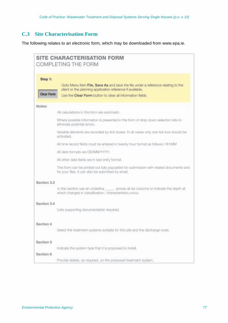
Code of Practice: Wastewater Treatment and Disposal Systems Serving Single Houses (p.e. ≤ 10)
C.3 Site Characterisation Form
The following relates to an electronic form, which may be downloaded from www.epa.ie.
Environmental Protection Agency 77
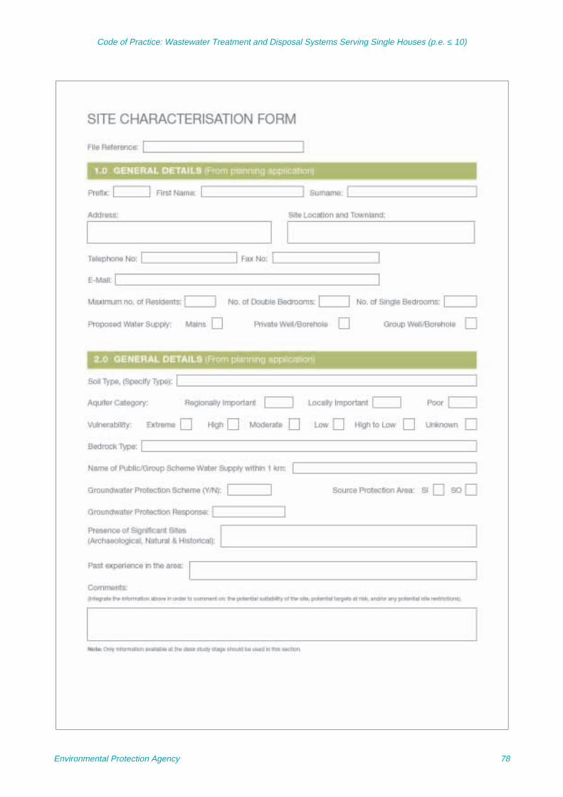
Code of Practice: Wastewater Treatment and Disposal Systems Serving Single Houses (p.e. ≤ 10)
Environmental Protection Agency 78

Code of Practice: Wastewater Treatment and Disposal Systems Serving Single Houses (p.e. ≤ 10)
Environmental Protection Agency 79

Code of Practice: Wastewater Treatment and Disposal Systems Serving Single Houses (p.e. ≤ 10)
Environmental Protection Agency 80

Code of Practice: Wastewater Treatment and Disposal Systems Serving Single Houses (p.e. ≤ 10)
Environmental Protection Agency 81

Code of Practice: Wastewater Treatment and Disposal Systems Serving Single Houses (p.e. ≤ 10)
Environmental Protection Agency 82

Code of Practice: Wastewater Treatment and Disposal Systems Serving Single Houses (p.e. ≤ 10)
Environmental Protection Agency 83

Code of Practice: Wastewater Treatment and Disposal Systems Serving Single Houses (p.e. ≤ 10)
Environmental Protection Agency 84

Code of Practice: Wastewater Treatment and Disposal Systems Serving Single Houses (p.e. ≤ 10)
Environmental Protection Agency 85

Code of Practice: Wastewater Treatment and Disposal Systems Serving Single Houses (p.e. ≤ 10)
Environmental Protection Agency 86

Code of Practice: Wastewater Treatment and Disposal Systems Serving Single Houses (p.e. ≤ 10)
Environmental Protection Agency 87
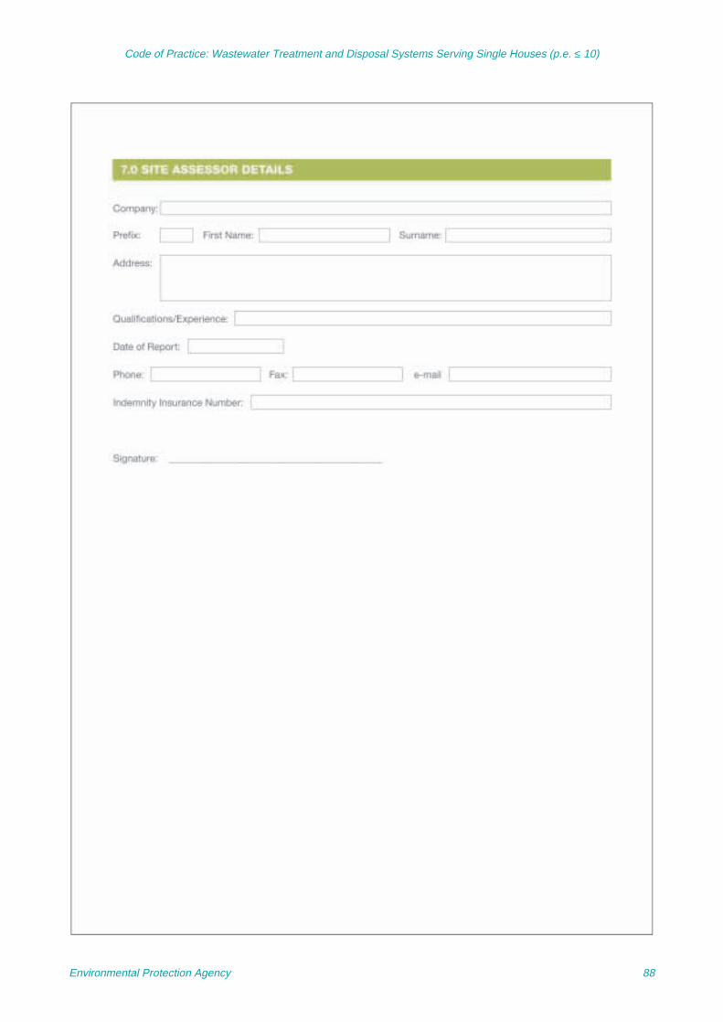
Code of Practice: Wastewater Treatment and Disposal Systems Serving Single Houses (p.e. ≤ 10)
Environmental Protection Agency 88

Code of Practice: Wastewater Treatment and Disposal Systems Serving Single Houses (p.e. ≤ 10)
Annex D Discharge Options
D.1 Water Pollution Licensing
The discharge of any sewage effluent towaters9 requires a licence under the WaterPollution Acts 1977–1990. The local authoritiesprocess these licence applications. Directdischarges to groundwater of listed substancesare prohibited by the Groundwater Directive(80/68/EEC). Discharges to groundwaterreferred to in this code are discharges viaunsaturated subsoil and hence are consideredindirect discharges.
D.2 Dilution Calculations
D.2.1 Dilution calculations for indirectdischarges to groundwater
In high-density areas or where the receivinggroundwater already has relatively high levelsof nitrate or phosphorus then a simple dilutioncalculation should be carried out to assess thepotential impact of the development of thereceiving water prior to licence being granted.In all cases planning permission and adischarge licence (where required) need to bein place prior to development of the site. Thefollowing is an example of a dilutioncalculation10 to assess the impact of effluent onnitrate concentrations in water (phosphoruscalculations should be used in phosphorus-sensitive locations):
Assumptions:• Recharge (rainfall – (evapotranspiration +
run-off)) = 13.7 m3/day/ha (500 mm/year)
• Average nitrogen (N) concentrations indomestic wastewater treatment effluent = 90 mg/l N
• Average flow from septic tank (4 persons)
= 0.72 m3/day
• Average nitrogen concentration in recharge= 0.1 mg/l N
• Assume that total-N load in septic tankeffluent (in form of ammonium and organicN) is totally nitrified to nitrate in the subsoiland that no denitrification occurs11
• Nitrate concentration resulting from 1 on-site system/ha = (avg. total-N conc. in septic tank effluent ×flow) + (avg. nitrate conc. in recharge ×recharge) divided by flow plus recharge
= 6.71 mg/l N or 29.71 mg/l NO3
The only parameter that is needed to vary isrecharge, which could be reduced in the driercounties. Recharge figures may be obtainedfrom Met Éireann. This calculation can becombined with knowledge/existing waterquality data. A decision can then be made as towhether or not the increased nitrogen levels areacceptable when compared to the relevantnational standards.
D.2.2 Discharges to surface waterWhere sites are unsuitable for discharge ofeffluent to ground it is usually due to hydraulicreasons or high water tables. The failure couldbe as a result of impervious soil and/or subsoiland/or poorly permeable bedrock, which mayresult in ponding on-site. In these cases siteimprovement works are unlikely to render thesite suitable for discharge to ground and theonly possible discharge route is to surfacewater in accordance with a Water Pollution Actlicence.
Where it is proposed to discharge wastewaterto any surface waters a licence is required
9. Includes any (or any part of any) river, stream, lake, canal,reservoir, aquifer, pond, watercourse or other inland waters,whether natural or artificial.
10. Section 13.2.14.6 Site Specific Evaluation, Site SuitabilityAssessments for On-Site Wastewater Management, FÁSCourse Manual, Vol. 2.
11. ERTDI 27 – 2000-MS-15-M1 An Investigation into thePerformance of Subsoils and Stratified Sand Filters for theTreatment of Wastewater from On-Site Systems.
=(90 × 0.72) + (0.1 × 13.7)
(0.72 + 13.7)
Environmental Protection Agency 89
Code of Practice: Wastewater Treatment and Disposal Systems Serving Single Houses (p.e. ≤ 10)
(which is a separate procedure) and the localauthorities should risk-assess the impact of thedischarge from the on-site system on thereceiving water including the assimilativecapacity of the receiving water, the ongoingmonitoring of the system performance, and acost analysis. It should be noted that many
local authorities currently do not favourgranting discharge licences to surface watersfor single houses. For further guidance pleasesee the EPA Waste Water Discharge LicensingApplication Guidance Note (2008) (available onwww.epa.ie).
Environmental Protection Agency 90

Code of Practice: Wastewater Treatment and Disposal Systems Serving Single Houses (p.e. ≤ 10)
Annex E Wastewater Treatment and Disposal Systems
This section gives an overview of the maincategories of wastewater treatment systemsavailable; more detailed descriptions are givenin this CoP. Where new and innovativeproducts and technologies are proposed, thelocal authority should satisfy itself that theproducts/technologies have proven trackrecords based on good science demonstratedin other jurisdictions. In the case of treatmentsystems such new systems should comply withthe requirements of EN 12566 or equivalent.
E.1 Septic Tank System
A septic tank system (Section 7) comprises aseptic tank followed by a soil percolation area.The septic tank functions as a two-stageprimary sedimentation tank, removing most ofthe suspended solids from the wastewater.This removal is accompanied by a limitedamount of anaerobic digestion, mostly duringthe summer months under warmertemperatures. The percolation area providesadditional treatment (secondary and tertiary) ofthe wastewater and it provides the majority ofthe treatment. The wastewater from the septictank is distributed to a suitable soil percolationarea, which acts as a bio-filter. The biomat is abiologically active layer, which containscomplex bacterial polysaccharides andaccumulated organic substances and micro-organisms which treat the effluent. The biomatcontrols the rate of percolation into the subsoil(Fig. E.1). As the wastewater flows into andthrough the subsoil, it undergoes surfacefiltration, straining, physico-chemicalinteractions and microbial breakdown.Secondary-treated effluent has a lower organicloading than septic tank effluent, which leads toa reduction in lateral spread of the biomat. Afterpercolating through a suitably designed andmaintained percolation area, the wastewater issuitable for indirect discharge to ground.
Failure of a septic tank system to functionproperly is generally due to poor construction,installation, operation, lack of maintenance,installation in an area of unsuitable ground
conditions, or the use of a soakaway instead ofa properly designed percolation area.
The attributes of septic tanks are outlined inTable E.1. The following guidance on thegeneral design of conventional rectangularseptic tanks should help ensure bestperformance.
• Septic tanks should comprise twochambers and it is recommended that theyhave a minimum length to width ratio of 3:1in order to promote settlement ofsuspended solids
• Oversized rather than undersized septictanks are better because of greatersettlement of solids and larger hydraulicretention time for liquid and solids
• Properly designed baffles provide quiescentconditions and minimise the discharge ofsolids to the percolation area
• The inlet and outlet of the septic tank shouldbe separated by a long flow path for thewastewater; if the outlet is too close to theinlet, solids settlement and greaseseparation may be inadequate
• Access and inspection openings should beincorporated into the roof of the septic tank.The opening should be constructed to suchstandard and in such a manner thatunintended access (for example bychildren) cannot occur, and
• T-pieces should be installed as they preventsolids carry-over into the effluent, assist inthe formation of a surface scum layer whichtraps floating solids and grease and assistin preventing odours.
Septic tanks should:
• Be able to withstand corrosion fromwastewater and gases
• Be able to safely carry all lateral and verticalsoil pressures
Environmental Protection Agency 91
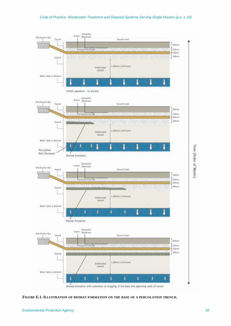
Code of Practice: Wastewater Treatment and Disposal Systems Serving Single Houses (p.e. ≤ 10)
FIGURE E.1. ILLUSTRATION OF BIOMAT FORMATION ON THE BASE OF A PERCOLATION TRENCH.
Environmental Protection Agency 92

Code of Practice: Wastewater Treatment and Disposal Systems Serving Single Houses (p.e. ≤ 10)
• Be able to accommodate water pressurefrom inside and outside the tank withoutleakage occurring
• Should be watertight to prevent wastewaterescaping to the soil outside, and to preventsurface water and groundwater fromentering the tank, and
• All septic tanks should be followed by apercolation area that is in compliance withI.S. CEN/TR 12566:2.
E.2 Secondary Treatment: On-SiteFilter Systems
Filter systems are used to provide additionaltreatment of upstream septic tank or packagedtreatment systems. These include intermittentlypumped (dosed) soil filters and sand filters(Section 8).
Soil filters comprise suitable soils placed oftenin the form of a mound (but may beunderground or part below ground/part aboveground), through which septic tank effluent isfiltered and treated.
Intermittently dosed sand filters consist of oneor more beds of graded sand underlain at thebase by a gravel or permeable soil layer toprevent outwash or piping of the sand; soil-
covered intermittent sand filters may beunderground, part underground and partoverground, or overground. The latter twoconstructions are commonly referred to asmound systems.
All intermittent filter systems should incorporatepolishing filters to provide additional treatmentof the effluent by reducing pollutants such assuspended solids, micro-organisms, andphosphorus (depending on the media).Polishing filters also provide for the hydraulicconveyance of the treated effluent to ground.
Constructed wetlands (reed beds) areconsidered to be another form of filter systemand can also be used for the treatment ofwastewater from single houses. Constructedwetlands should be underlain by either animpermeable geo-synthetic membrane or animpermeable clay liner (k = 1 × 10⁻⁸ m/s) toprevent leakage to the groundwater. Primarytreatment by a septic tank is used prior todischarge to a constructed wetland. In thewetland, the wastewater from a septic tankundergoes secondary treatment by acombination of physical, chemical andbiological processes that develop through theinteraction of the plants (reeds), the growingmedia (gravel) and micro-organisms beforedischarge of the effluent to groundwater or
TABLE E.1. ATTRIBUTES OF A TYPICAL SEPTIC TANK.
A properly constructed septic tank will:
• Retain and remove 50% or more solids
• Allow some microbial decomposition
• Accept sullage (i.e. water from baths, wash-hand basins, etc.)
• Accept water containing detergents (e.g. washing machine, dishwasher, etc.)
• Reduce clogging in the percolation area
• Not fully treat domestic wastewater
• Not work properly if not regularly maintained
• Not significantly remove micro-organisms
• Not remove more than 15–30% of the biological oxygen demand (BOD)
• Not operate properly if pesticides, paints, thinners, solvents, excess disinfectants or household hazardous substances are discharged to it
• Not accommodate sludge indefinitely
• Not operate properly if surface waters (i.e. roofs, parking areas, etc.) are discharged to it
Environmental Protection Agency 93
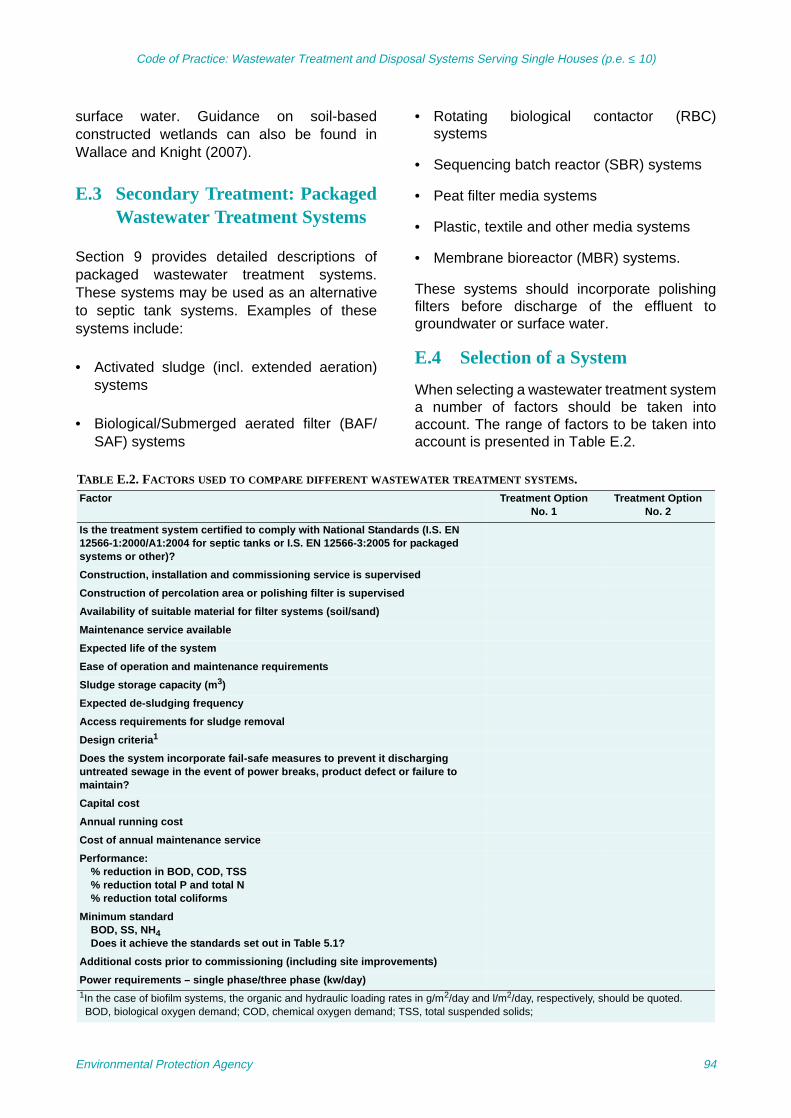
Code of Practice: Wastewater Treatment and Disposal Systems Serving Single Houses (p.e. ≤ 10)
surface water. Guidance on soil-basedconstructed wetlands can also be found inWallace and Knight (2007).
E.3 Secondary Treatment: PackagedWastewater Treatment Systems
Section 9 provides detailed descriptions ofpackaged wastewater treatment systems.These systems may be used as an alternativeto septic tank systems. Examples of thesesystems include:
• Activated sludge (incl. extended aeration)systems
• Biological/Submerged aerated filter (BAF/SAF) systems
• Rotating biological contactor (RBC)systems
• Sequencing batch reactor (SBR) systems
• Peat filter media systems
• Plastic, textile and other media systems
• Membrane bioreactor (MBR) systems.
These systems should incorporate polishingfilters before discharge of the effluent togroundwater or surface water.
E.4 Selection of a System
When selecting a wastewater treatment systema number of factors should be taken intoaccount. The range of factors to be taken intoaccount is presented in Table E.2.
TABLE E.2. FACTORS USED TO COMPARE DIFFERENT WASTEWATER TREATMENT SYSTEMS.Factor Treatment Option
No. 1Treatment Option
No. 2
Is the treatment system certified to comply with National Standards (I.S. EN 12566-1:2000/A1:2004 for septic tanks or I.S. EN 12566-3:2005 for packaged systems or other)?
Construction, installation and commissioning service is supervised
Construction of percolation area or polishing filter is supervised
Availability of suitable material for filter systems (soil/sand)
Maintenance service available
Expected life of the system
Ease of operation and maintenance requirements
Sludge storage capacity (m3)
Expected de-sludging frequency
Access requirements for sludge removal
Design criteria1
Does the system incorporate fail-safe measures to prevent it discharging untreated sewage in the event of power breaks, product defect or failure to maintain?
Capital cost
Annual running cost
Cost of annual maintenance service
Performance: % reduction in BOD, COD, TSS% reduction total P and total N% reduction total coliforms
Minimum standardBOD, SS, NH4Does it achieve the standards set out in Table 5.1?
Additional costs prior to commissioning (including site improvements)
Power requirements – single phase/three phase (kw/day)1In the case of biofilm systems, the organic and hydraulic loading rates in g/m2/day and l/m2/day, respectively, should be quoted.BOD, biological oxygen demand; COD, chemical oxygen demand; TSS, total suspended solids;
Environmental Protection Agency 94

Code of Practice: Wastewater Treatment and Disposal Systems Serving Single Houses (p.e. ≤ 10)
a. Certification of the systemAs per Part One of this CoP.
b. Wastewater treatment performancerequirementsThe standards set in Table 5.1 (Section 5)apply to these systems.
c. Degree of environmental protectionrequiredHaving completed the site assessment asoutlined in Section 6, a decision will need tobe made on the degree of environmentalprotection required.
d. CostA single-house treatment system will entailcapital, running and maintenance costs. Inchoosing a system due regard should begiven to the overall relative costs.
e. MaintenanceA number of issues related to themaintenance of the single-housewastewater treatment system will have tobe considered such as:
R Availability of competent persons andparts for the system
R Ease of access to the system in orderto perform maintenance, e.g. de-sludging
R Frequency of maintenance required
R Capacity to sample the effluentdischarge
R Sludge storage capacity.
f. Anticipated lifetime of the system.
g. Track record of the system.
Environmental Protection Agency 95
Code of Practice: Wastewater Treatment and Disposal Systems Serving Single Houses (p.e. ≤ 10)
Annex F Site Improvement Works
In certain circumstances a site that is intendedfor a single-house development will presentparticular difficulties arising out of the siteassessment. Some sites may have a highwater table, may have insufficient subsoildepth, or may have unsuitable subsoil for thepurposes of treatment and percolation of thepretreated wastewater from a treatmentsystem. It may be possible in some such casesto render the site suitable for development aftercarrying out specific engineering works on thesite known as ‘site improvements’. The optionto carry out site improvements might beconsidered in circumstances where a highwater table is a problem. The conditions thatgive rise to a high water table are site specific;these include topography, nature of soils,bedrock and outfalls. Detailed designprocedures appropriate for site improvement
works are available in drainage manuals(Mulqueen et al., 1999).
In other cases, such as where the site isoverlain by insufficient depth of subsoil orunsuitable subsoil, the site may be improved bythe placement of suitable soil in lifts across thewhole site rather than just infilling in the areaaround a proposed mound system. It isnecessary to perform testing of each 300-mmlayer as the process of emplacing lifts of soilprogresses. After each lift is placed, percolationtests should be carried out. A 150-mm squarehole is excavated to a depth of 150 mm in theplaced soil. After pre-soaking to completely wetthe soil, 0.5 l of water is poured into the holeand the time in minutes for the water to soakaway is recorded. This time should be between10 min and 2 h.
Environmental Protection Agency 96

Code of Practice: Wastewater Treatment and Disposal Systems Serving Single Houses (p.e. ≤ 10)
Annex G Operation and Maintenance
G.1 Septic Tank Systems
The septic tank itself, the distribution systemand the percolation area all require inspectionto ensure effective operation of the system, andperiodic maintenance to ensure that the systemcontinues to work effectively over time.
G.1.1 Septic tankThe septic tank is a passive treatment unit thattypically requires little operator intervention.Regular inspections (approximately every 6months) and sludge pumping (at a minimumfrequency once every year) are the minimumoperation and maintenance requirements.
Inspections of septic tanks should includeobservation of sludge and scum accumulation,structural soundness, watertightness, andcondition of the inlet and condition of the outletfrom the tank.
G.1.1.1 Sludge and scum accumulationsAs wastewater passes through and is partiallytreated in the septic tank over the years, thelayers of floatable material (scum) andsettleable material (sludge) increase inthickness and gradually reduce the amount ofspace available for clarified wastewater. If thesludge layer builds up as far as the bottom ofthe effluent T-pipe, solids can be drawn throughthe effluent port and transported into thepercolation area, thus increasing the risk ofclogging. Likewise, if the bottom of thethickening scum layer builds downwards as faras the bottom of the effluent T-pipe, oils andother scum material can be drawn into the
piping that discharges to the percolation field.The scum layer should not extend above thetop or below the bottom of either the inlet oroutlet T-pipes. The top of the sludge layershould be at least 30 cm below the bottom ofeither tee or baffle. Usually, the sludge depth isgreatest below the inlet baffle. The bottom ofthe scum layer should not be less than 10 cmabove the bottom of the outlet T-pipe or baffle.If any of these conditions are present, there isa risk that wastewater solids will plug the tankinlet or be carried out in the tank effluent andbegin to clog the percolation area associatedwith the septic tank.
The depth of sludge can be checked using thefollowing technique or any other appropriatemethod:
• Use a 2-m pole and wrap the bottom 1.2-mwith a white rag
• Lower the pole to the bottom of the tank andhold there for several minutes to allow thesludge layer to penetrate the rag, and
• Remove the pole and note the sludge line,which will be darker than the colorationcaused by the liquid waste.
G.1.1.2 Structural soundness and watertightnessStructural soundness and watertightness arebest observed after sludge has been pumpedfrom the tank. The interior tank surfaces shouldbe inspected for deterioration, such as pitting,spalling, delamination, and so forth, and forcracks and holes. The presence of roots, forexample, indicates tank cracks or open joints.These observations can be made with a mirrorand bright light (such as a torch or flash lamp).Watertightness can be checked by observingthe liquid level (before pumping), observing alljoints for seeping water or roots, and listeningfor running or dripping water. Before pumping,the liquid level of the tank should be at theoutlet invert level. If the liquid level is below theoutlet invert, leaking is occurring. If it is above,the outlet is obstructed or the percolation areais flooded. A constant trickle from the inlet is an
Warning:In performing inspections or other maintenance,a septic tank should not be entered. The septictank is a confined space and entering can beextremely hazardous because of toxic gasesand/or insufficient oxygen. Electrical appliancessuch as mains-powered lighting should not beused near a septic tank.
Environmental Protection Agency 97
Code of Practice: Wastewater Treatment and Disposal Systems Serving Single Houses (p.e. ≤ 10)
indication that plumbing fixtures in the buildingserved by the tank are leaking and need to beinspected, or that infiltration of groundwaterinto the inlet pipe is taking place.
G.1.1.3 Baffles and screensThe baffles should be observed to confirm thatthey are in the proper position, secured well tothe piping or tank wall, clear of debris, and notcracked or broken. If an effluent screen is fittedto the outlet baffle, it should be removed,cleaned, inspected for irregularities, andreplaced. Note that effluent screens should notbe removed until the tank has been pumped orthe outlet is first plugged.
G.1.1.4 Septic tank pumping and de-sludgingTanks should be pumped when sludge andscum accumulations exceed 30% of the tankvolume or are encroaching on the inlet andoutlet baffle entrances. Periodic pumping ofseptic tanks is recommended to ensure propersystem performance and reduce the risk ofhydraulic failure. Septic tanks should be de-sludged at a minimum of once every year. Incases where the septic tank is at, or near, itsdesign load capacity, de-sludging should bemore often if the rate of sludge build-uprequires more frequent removal. Accumulatedsludge and scum material found in the tankshould be removed by an appropriatelypermitted contractor (in accordance with theWaste Management (Collection Permit)Regulations 2001). The local authorities have alist of permitted contractors in the area. Thepermitted contractor will arrange for thedisposal of the sludge in accordance with thenational legislation (via either disposal toagriculture or disposal to a managedwastewater treatment municipal facility).Householders obtain a certificate from thepermitted contractor each time their tank is de-sludged.
Sludge from a septic tank or a sewagetreatment system that is intended to belandspread should be managed in accordancewith the Waste Management (Use of SewageSludge in Agriculture) Regulations S.I. No. 148of 1998 (and its amendment S.I. No. 267 of2001). These regulations allow for thelandspreading of sewage sludge on agriculturalland providing that certain criteria are met and
that it is carried out in accordance with thenutrient management plan for the lands inquestion.
G.1.2 The distribution device
The effluent from the septic tank is typicallyconveyed to the percolation area through adistribution device, housed in a distribution box.The function of the device is to evenly split thehydraulic flow of partially treated effluent into anumber of approximately equal volumes foronward discharge to the individual percolationpipes in the percolation area.
The distribution box should be inspected atintervals of no greater than every 6 months.Build-up of solids in the distribution deviceshould be removed to ensure that the flowthrough the device is not obstructed, and toensure that the effluent passing through isevenly split between the outlet pipes. Thedistribution device should be checked toensure that it has not shifted on its foundationsince the previous inspection. Suchdisturbance can result from overpassing byheavy vehicles or through natural soil creep.Where such disturbance has taken place, acompetent person should reset the distributiondevice on its foundation, and the level of thedistribution device should be rechecked as partof this measure. Any damage to the box itself,its internal pipework, the jointing to the externalinlet and outlet pipes, or to the cover of thedevice should be made good as part of themaintenance procedure.
G.1.3 The percolation area
The percolation area requires little in the way ofregular maintenance in situations where aproper site assessment has been carried outprior to installation, where the system has beeninstalled correctly, and where no physicaldamage has been done to the surface afterinstallation. The percolation area should bekept free from disturbance from vehicles, heavyanimals, sports activities or other activitieslikely to break the sod on the surface. If thearea has been grassed then the excess growthof grass can be mown and removedperiodically. The use of gardening tools, whichmight break the surface, should be avoided.
Environmental Protection Agency 98

Code of Practice: Wastewater Treatment and Disposal Systems Serving Single Houses (p.e. ≤ 10)
The percolation area should be inspected at 6-monthly intervals to ensure that no surfacedamage has taken place. The aeration/ventpipes should be inspected to ensure that theyare still in place and intact. If possible, theinside of the vents should be examined to verifythat they are dry and free from obstruction. Thesurface of the ground in the percolation areashould be walked and examined to ensure thatit is free from surface or superficial damage andto ensure that ponding of effluent is notoccurring.
Where any damage is observed the followingprocedures should be followed:
• Where ponding of effluent is noted at thesurface it may be necessary to excavate thepercolation area to investigate the reasonfor the hydraulic failure of the distributionsystem
• Where such ponding is due to damage ofthe percolation pipework the necessaryrepairs should be carried out by acompetent person
• Any damage to aeration/vent pipes shouldbe made good, and
• The surface of the ground over thepercolation pipes should be reinstated andre-vegetated, and further damage to theground surface should be avoided bycontrolling activities on the surface.
G.2 Filter Wastewater TreatmentSystems
G.2.1 Intermittent soil and sand filtersThe main tasks are servicing of the dosingequipment (pump and distribution manifold)and monitoring of the wastewater. In the caseof sand filters, there is possible maintenance ofthe sand surface of open sand filters. When de-sludging the septic tank, the pump sump shouldalso be de-sludged. After de-sludging thechamber, the pump unit should be hosed downand the washwater and sludge be removedfrom the pump chamber. The distributionmanifold needs to be cleaned periodically (atleast once every 6–12 months) and so needs tobe designed to facilitate such an operation. The
use of backpressure gauges and zonedregions will facilitate the maintenance ofdistribution manifolds.
The performance of the pump system shouldbe checked, including the pump sump, pumpbase, the float position and operation, a checkfor blockages and volume delivered.
G.2.2 Mounded filter systemsThe most common failures in mound systemsare the granular fill material/filter materialinterface in the mound. The quantity and qualityof wastewater or the fill material can lead topotential failures. Failures due to compactionand ponding are often seen as leakage at theinterface between the soil and filter material.Hydraulic failure can occur in mounds due toexcessive ponding within the absorption areaor leaking out of the toe of the mound. Pondingcan occur where a flow rate across the granularfill/filter material interface is less than the flowrate from the dosing chamber. This may be dueto a number of causes, namely:
• Restricted clogging of the distribution pipes
• The filter material is too fine
• The loading rate is too great, or
• A combination of these factors.
Particular care should be taken to avoidcompaction or disturbance of the area over andaround the infiltration system. The dosingchamber should be kept clear of obstructionand should be checked for correct distributionand the outlets should be adjusted if necessary.All electrical and mechanical devices should beserviced in accordance with the manufacturer’sinstructions. Monitoring tubes should beinstalled to allow for the inspection of themound without unearthing the filter material orremoving the access port. These should be100-mm diameter vertical pipes with 6- to 8-mmdiameter holes (or slots) drilled down the lengthand covered with geotextile for soil filters. Anyprogressive increase in the depth of water inthe monitoring tubes may indicate a problem.The dosing chamber should be pumped out atleast once every 3–5 years or as required bythe manufacturer’s specifications. The pumpchamber (sump) should be fitted with a high-
Environmental Protection Agency 99

Code of Practice: Wastewater Treatment and Disposal Systems Serving Single Houses (p.e. ≤ 10)
level alarm to alert the homeowner to apossible pump failure or blocked distributionpipework. Grass and other vegetation coveringthe mound should be maintained, in order tomaximise water uptake and to prevent erosion.Trees or shrubs with extensive root systemsshould not be planted on or near the mound, asthey may clog the drainage pipes or causeshort-circuiting of the filter material.
G.2.3 Constructed wetlandsConstructed wetlands require some inspectionand maintenance to avoid the occurrence ofproblems within the system. It takesapproximately 4 weeks or so for the plants tosettle in after planting and they generallybecome fully established within the first 2years. Plants should be healthy and it ispreferable to plant before the growing season.Seedlings and rhizomes should be planted toensure early establishment and to stop thembecoming overwhelmed by weeds. Thewetland should be kept moist during periods ofdry weather especially during the first year orso, to ensure plant health. This is only neededif water is not discharging from the outlet due topercolation through clay substrates or due tohigh plant evapotranspiration rates combinedwith low summer use.
Routine inspections are necessary to ensureappropriate flows through the inlet distributorand outlet collector piping, as well as for thedetection of leakage from the pipework.Regular de-sludging of preliminary orsecondary treatment systems upstream of thewetland is needed to prevent sludge carry-overand accumulation at the wetland inlet. Grassand wetland vegetation should be checked toidentify any visible signs of plant stress ordisease. Common symptoms of plant stressare grass yellowing and leaf damage. Aspecialist or the system supplier should beconsulted if signs of plant stress are spotted.Flow distribution within the cells should beinspected from time to time in order to detectchannel formation or short-circuiting, especiallyin horizontal flow systems. The planting ofadditional vegetation or filling soil in anychannels that have formed can correct this. Allpipework and pumps should be checkedregularly to ensure that they are operatingproperly and that there are no signs of clogging.
Flow meters and timers should be checked toensure that the right amount of effluent is beingapplied to the system. In order to maximise thehealthy bacterial activity and overalleffectiveness of the treatment system, the useof bleaches and other toxic chemicals from thewastewater stream should be minimised oreliminated if possible.
G.3 Packaged Wastewater TreatmentSystems
Packaged wastewater treatment systems areconfigured in various ways and the systemmanufacturer often dictates the frequency andmethod of maintenance. When seeking specificguidance for the maintenance of such systemsthe user should consult the instructionsprovided by the manufacturer, or refer to anyinformation provided about the maintenance ofthe system in the appropriate AgrémentCertificate or standard. In some (but not all)cases, maintenance is offered by themanufacturer through a maintenance contract.Maintenance may also be availablecommercially by appropriately qualified serviceproviders.
In general, it is possible to comment on the keyitems of mechanical and electrical equipmentincluded in many such treatment systems, andsome direction in regard to maintenance can beprovided.
G.3.1 Checks that may be carried out by theuser
• The warning alarm system:
R Many of the latest packaged wastewatertreatment systems are equipped with analarm circuit. The purpose of this circuit
WarningProprietary wastewater treatment systems,which incorporate mechanical and/or electricalcomponents, are generally not userserviceable. Such units may be powered bymains electricity, and unqualified personsshould not attempt to perform maintenance onthem. To avoid serious injury or electrocution,servicing should only be carried out by qualifiedservice providers.
Environmental Protection Agency 100

Code of Practice: Wastewater Treatment and Disposal Systems Serving Single Houses (p.e. ≤ 10)
is to alert the user to any malfunctionthat has been diagnosed in the treatmentsystem by the built-in system monitoringdevices.
R Where the facility to do so has beenincorporated, the user shouldperiodically check the alarm circuit toensure that the system alarm is workingproperly. In most cases, it will bepossible to perform this check within theuser’s house or from a control boxoutside the house.
• Visual inspection:
R The user of a mechanical wastewatertreatment system should carry out aperiodic visual inspection of the externalelements of the treatment unit andpolishing filter.
• Odour observation:
R While carrying out the visual inspectionthe user should note any unusual odoursemanating from the mechanical aerationsystem. For example, pungent sulphide-like (bad egg) odours may indicateanaerobic conditions in the treatmentsystem. This may be indicative of abreakdown of the aeration equipmentand this should be investigatedthoroughly by a qualified serviceprovider.
• Noise:
R While carrying out the visual inspectionthe user should note any unusual noisesfrom the mechanical aeration system.For example, unusual noises comingfrom the treatment system may indicatethat there are problems with themechanical components (pump oraerator). Such problems may beassociated with partial blockages orcomponent wear and should be
investigated thoroughly by a qualifiedservice provider.
G.3.2 Proprietary filters For proprietary peat filter systems, it isadvisable that the manufacturer/competentperson assesses the quality of the media fromtime to time. The surface of the peat filtershould be examined periodically for signs ofponding and, where evident, the manufacturer/installer should be contacted. The peat mediashould not be disturbed as this may lead tochannelling of effluent or flooding. When de-sludging the septic tank, the pump chambershould also be de-sludged. After de-sludgingthe chamber, the pump unit should be hoseddown and the wash water and sludge beremoved from the pump chamber.
G.4 Polishing Filters
Where polishing filters have been installed witheither filter systems or packaged wastewatertreatment systems, these should beperiodically inspected in accordance with thegeneral principles outlined in Section 7. Inaddition, where polishing filters are situatedabove ground level, checks should be carriedout to ensure that no effluent is escaping fromthe filter above ground or at the interface withthe ground surface.
G.5 Holiday Homes
When choosing a wastewater treatmentsystem for holiday homes, considerationshould be given to the selection of a systemthat can adequately deal with periods ofinactivity (i.e. when the house is unoccupied forprolonged periods). Systems that are capableof recirculating the effluent would beappropriate. It is recommended thatbiodegradable cleaning agents be consideredfor use in holiday homes. All systems should beoperated and maintained in accordance withthe manufacturer’s instructions.
Environmental Protection Agency 101

Code of Practice: Wastewater Treatment and Disposal Systems Serving Single Houses (p.e. ≤ 10)
Annex H References and Reading Material
BS 5930:1999 Code of Practice for Site Investigations.British Standards Institution, UK.
BS 10175:2001 Investigation of potentially contaminatedsites – Code of Practice. British Standards Institution,UK.
Building Research Establishment (BRE) (1991).Soakaway Design. Building Research Establishment(BRE) Publications, BRE Press, UK.
Carey, C., Phelan, W. and Boland, C. (2008). Examiningthe Use of Food Waste Disposers (2005-WRM-DS-23-M1). Environmental Protection Agency, JohnstownCastle Estate, Wexford, Ireland.
CEC (1980). Council Directive 80/68/EEC of 17December 1979 on the protection of groundwateragainst pollution caused by certain dangeroussubstances. Council of the European Communities,O.J. L 20/43.
CEC (2000). Council Directive 2000/60/EC of theEuropean Parliament and of the Council of 23October 2000 establishing a framework forCommunity action in the field of water policy. Councilof the European Communities O.J. L 327.
CEN (2002). Wastewater Treatment Plants – Part 1.European Standard. I.S. EN 12255-1:2002. EuropeanCommittee for Standardization. Brussels, Belgium.
CEN (2005a). Small wastewater treatment systems forup to 50 PT – Part 2: Soil Infiltration Systems.Technical Report I.S. CEN/TR 12566-2:2005.European Committee for Standardization. Brussels,Belgium.
CEN (2005b). Small wastewater treatment systems forup to 50 PT – Part 3: Packaged and/or SiteAssembled Domestic Wastewater Treatment Plants.European Standard I.S. EN 12566-3:2005. EuropeanCommittee for Standardization. Brussels, Belgium.
CEN (2005c). Small wastewater treatment systems forup to 50 PT – Part 6: Prefabricated Treatment Unitsfor Septic Tank Effluent. European Standard prEN12566-6. European Committee for Standardization.Brussels, Belgium.
Cooper, P.F., Job, G.D., Green, M.B. and Shutes, R.B.E.(1996). Reed Beds and Constructed Wetlands forWastewater Treatment. Water Research Centre,Swindon, UK.
Daly, D. (2006). Site Suitability for On-Site WastewaterTreatment Systems – the Role of the Water Table.Groundwater Newsletter No. 45 issued by theGeological Survey of Ireland, Dublin, Ireland.
DELG (Department of Environment and Local
Government) (1992). Environmental ProtectionAgency Act, 1992. Statutory Number 7 of 1992.Government Publications Office, Dublin 2, Ireland.
DELG/EPA/GSI (Department of Environment and LocalGovernment/Environmental Protection Agency/Geological Survey of Ireland) (1999). GroundwaterProtection Schemes. Geological Survey of Ireland,Dublin, Ireland.
DoEHLG (Department of the Environment, Heritage andLocal Government) (2003). Protection of theEnvironment Act, Statutory Instrument, Number 27 of2003. Government Publications Office, Dublin 2,Ireland.
DoEHLG (Department of the Environment, Heritage andLocal Government) (2005). Safety, Health andWelfare at Work Act, Statutory Number 10 of 2005Government Publications Office, Dublin 2, Ireland.
DoELG/EPA/GSI (Department of Environment and LocalGovernment/Environmental Protection Agency/Geological Survey of Ireland) (1999a). GroundwaterProtection Responses for Landfills. GeologicalSurvey of Ireland, Dublin, Ireland.
DoELG/EPA/GSI (Department of Environment and LocalGovernment/Environmental Protection Agency/Geological Survey of Ireland) (1999b). GroundwaterProtection Responses to the Landspreading ofOrganic Wastes. Geological Survey of Ireland,Dublin, Ireland.
DoELG/EPA/GSI (Department of Environment and LocalGovernment/Environmental Protection Agency/Geological Survey of Ireland) (2001). GroundwaterProtection Responses for On-Site Systems for SingleHouses. Geological Survey of Ireland, Dublin, Ireland.
EPA (1999). Wastewater Treatment Manuals: TreatmentSystems for Small Communities, Business, LeisureCentres and Hotels. Environmental ProtectionAgency, Johnstown Castle Estate, Wexford, Ireland.
EPA (2000). Wastewater Treatment Manuals: TreatmentSystems for Single Houses. Environmental ProtectionAgency, Johnstown Castle Estate, Wexford, Ireland.
EPA (2008), Waste Water Discharge LicensingApplication Guidance Note. Environmental ProtectionAgency, Johnstown Castle Estate, Wexford, Ireland.
Gill, L.W., Hand A. and O’Súilleabháin C. (2004).Effective distribution of domestic wastewater effluentbetween percolation trenches in on-site treatmentsystems. Water Science and Technology 51(10): 39–46.
Gill, L.W., O’Súilleabháin, C., Misstear, B.D.R. and
Environmental Protection Agency 102
Code of Practice: Wastewater Treatment and Disposal Systems Serving Single Houses (p.e. ≤ 10)
Johnston, P.J. (2004). A comparison of stratified sandfilters and percolation trenches for the treatment ofdomestic wastewater effluent. Proceedings of the 1stInternational Conference on Onsite WastewaterTreatment and Recycling (IWA). Freemantle,Australia: 11–13 February 2004.
Gill, L.W., O’Súilleabháin, C., Misstear, B.D.R. andJohnston, P.J. (2005). An Investigation into thePerformance of Subsoils and Stratified Sand Filtersfor the Treatment of On-Site Wastewater. 2001-MS15-M1: Synthesis Report, EnvironmentalProtection Agency, Johnstown Castle Estate,Wexford, Ireland.
Gill, L.W., O’Súilleabháin, C., Johnston, P.M. andMisstear, B.D.R. (2005). An Investigation into thePerformance of Subsoils and Stratified Sand Filtersfor the Treatment of Wastewater from On-SiteSystems. Synthesis Report, Environmental ProtectionAgency, Johnstown Castle Estate, Wexford, Ireland.
Gill, L.W., O’Súilleabháin, C., Misstear, B.D.R. andJohnston, P.J. (2007). The treatment performance ofdifferent subsoils in Ireland receiving on-sitewastewater effluent. Journal of Environmental Quality36(6): 1843–1855.
Gill, L., Ó’Luanaigh, N., Patel, T., Misstear, B. andJohnston, P. (2009a). The Treatment of On-SiteWastewater in Rapid Percolating Subsoils and ReedBeds and Investigation into the Effective Distributionof Effluent Across Percolation Areas. EnvironmentalProtection Agency, Johnstown Castle Estate,Wexford, Ireland. (in press)
Gill, L.W., O’Súilleabháin, C., Misstear, B.D.R. andJohnston, P. (2009b). Comparison of stratified sandfilters and percolation trenches for on-site wastewatertreatment. Journal of Environmental EngineeringASCE/January 2009: 8–16.
Grant, N. and Griggs, J. (2001). Reed Beds for theTreatment of Domestic Wastewater. BuildingResearch Establishment (BRE) Publications, BREPress, UK.
Gray, N.F. (1995). Composition of septic tank effluent.The GSI Groundwater Newsletter 27: 8.
Hellström, D. and Jonsson, L. (2003). Evaluation of smallwastewater treatment systems. Water Science &Technology 48(11–12): 61–68.
Jackson, B.J. (2005). Investigation into the Correlationsbetween the BS5930 SOIL CLASSIFICATIONS andPercolation Tests Used in Site SuitabilityAssessments for On-Site Waste Water EffluentTreatment. MSc Thesis. Department of Civil,Structural and Environmental Engineering, TrinityCollege Dublin, Ireland.
Kadlec, R. and Knight, R. (1996). Treatment Wetlands.CRC Press, Boca Raton, FL, USA.
Kadlec, R.H., Tanner, C.C., Hally, V.M. and Gibbs, M.M.(2005). Nitrogen spiraling in subsurface-flowconstructed wetlands: implications for treatmentresponse. Ecological Engineering 25: 365–381.
Molle, P., Liénard, A., Grasmick, A. and Iwema, A.(2003). Phosphorus retention in subsurfaceconstructed wetlands: investigations focused oncalcareous materials and their chemical reactions.Water Science & Technology 48(5): 75–84.
Mulqueen, J. and Rodgers, M. (2001). Percolation testingand hydraulic conductivity of soils for percolationareas. Water Research 35(16): 3909–3915.
Mulqueen, J., Rodgers, M., Hendrick, E., Keane, M. andMcCarthy, R. (1999). Forest Drainage Engineering.COFORD, Dublin, Ireland.
Nichols, D.J., Wolf, D.C., Gross, M.A. and Rutledge, E.M.(1997). Renovation of Septic Effluent in a StratifiedSand Filter. ASTM STP 1324. American Society forTesting and Materials, PA, USA.
O’Súilleabháin, C., Gill, L.W., Misstear, B.D.R. andJohnston, P.M. (2008). Fate of endocrine-disruptingchemicals in percolating domestic wastewatereffluent. Water and Environment Journal (in press).
Patel, T., O’Luanaigh, N. and Gill, L.W. (2008). Acomparison of gravity distribution devices used in on-site domestic wastewater treatment systems. Journalof Water, Air & Soil Pollution 191(1–4): 55–69.
Phelps, R.D.S. and Griggs, J. (2005). Mound FilterSystems for the Treatment of Domestic Wastewater.Building Research Establishment (BRE) Publications,BRE Press, UK.
University of Wisconsin-Madison (1978). Management ofSmall Wastewater Flows. EPA 600/7-78-173. USEnvironmental Protection Agency, Office of Researchand Development, Municipal EnvironmentalResearch Laboratory, Cincinnati, OH, USA.
US EPA (1992). Wastewater Treatment/Disposal forSmall Communities. Manual No. EPA/625/R-92/005.US Environmental Protection Agency, USA.
US EPA (1993). Subsurface Flow Constructed Wetlandsfor Wastewater Treatment: A TechnologyAssessment. EPA/832/R/93/001. USEPA Office ofWater, Washington, DC, USA.
US EPA (2002). Onsite Wastewater Treatment SystemsManual. No. EPA/625/R-00/008, Office of Water,Office of Research and Development, USEnvironmental Protection Agency, USA.
Van Cuyk, S., Siegrist, R., Lowe, K., Drewes, J.,Munakata-Marr, J. and Figueroa, L. (2005).Performance of engineered treatment units and theireffects on biozone formation in soil and systempurification efficiency. National Decentralized WaterResources Capacity Development Project(NDWRCDP) Research Project (WU-HT-03-36).
Environmental Protection Agency 103
Code of Practice: Wastewater Treatment and Disposal Systems Serving Single Houses (p.e. ≤ 10)
Submitted by the Colorado School of Mines, Golden,Colorado, USA.
Wakida, F.T. and Lerner, D.N. (2005). Non-agriculturalsources of groundwater nitrate: a review and casestudy. Water Research 39: 3–16.
Wallace, S. and Knight, R. (2007) Small-ScaleConstructed Wetland Treatment Systems –
Feasibility, Design Criteria and Operational &Monitoring Requirements. IWAP ISBN 1-84339-728-5.
Zhu, T., Mæhlum, T., Jenssen, P.D. and Krogstad, T.(2003). Phosphorus sorption characteristics of a light-weight aggregate. Water Science & Technology56(5): 93–100.
Environmental Protection Agency 104
Is í an Gníomhaireacht um Chaomhnú Comhshaoil (EPA) comhlachta reachtúil a chosnaíonn an comhshaol do mhuintir na tíre go léir. Rialaímid agus déanaimid maoirsiú ar ghníomhaíochtaí a d’fhéadfadh truailliú a chruthú murach sin. Cinntímid go bhfuil eolas cruinn ann ar threochtaí comhshaoil ionas go nglactar aon chéim is gá. Is iad na príomh-nithe a bhfuilimid gníomhach leo ná comhshaol na hÉireann a chosaint agus cinntiú go bhfuil forbairt inbhuanaithe.
Is comhlacht poiblí neamhspleách í an Ghníomhaireacht um Chaomhnú Comhshaoil (EPA) a bunaíodh i mí Iúil 1993 faoin Acht fán nGníomhaireacht um Chaomhnú Comhshaoil 1992. Ó thaobh an Rialtais, is í an Roinn Comhshaoil agus Rialtais Áitiúil a dhéanann urraíocht uirthi.
ÁR bhFREAGRACHTAÍ
CEADÚNÚ
Bíonn ceadúnais á n-eisiúint againn i gcomhair na nithe seo a leanas chun a chinntiú nach mbíonn astuithe uathu ag cur sláinte an phobail ná an comhshaol i mbaol:
• áiseanna dramhaíola (m.sh., líonadh talún, loisceoirí, stáisiúin aistrithe dramhaíola);
• gníomhaíochtaí tionsclaíocha ar scála mór (m.sh., déantúsaíocht cógaisíochta, déantúsaíocht stroighne, stáisiúin chumhachta);
• diantalmhaíocht;
• úsáid faoi shrian agus scaoileadh smachtaithe Orgánach Géinathraithe (GMO);
• mór-áiseanna stórais peitreail;
• scardadh dramhuisce.
FEIDHMIÚ COMHSHAOIL NÁISIÚNTA
• Stiúradh os cionn 2,000 iniúchadh agus cigireacht de áiseanna a fuair ceadúnas ón nGníomhaireacht gach bliain.
• Maoirsiú freagrachtaí cosanta comhshaoil údarás áitiúla thar sé earnáil - aer, fuaim, dramhaíl, dramhuisce agus caighdeán uisce.
• Obair le húdaráis áitiúla agus leis na Gardaí chun stop a chur le gníomhaíocht mhídhleathach dramhaíola trí comhordú a dhéanamh ar líonra forfheidhmithe náisiúnta, díriú isteach ar chiontóirí, stiúradh fiosrúcháin agus maoirsiú leigheas na bhfadhbanna.
• An dlí a chur orthu siúd a bhriseann dlí comhshaoil agus a dhéanann dochar don chomhshaol mar thoradh ar a ngníomhaíochtaí.
MONATÓIREACHT, ANAILÍS AGUS TUAIRISCIÚ AR AN GCOMHSHAOL
• Monatóireacht ar chaighdeán aeir agus caighdeáin aibhneacha, locha, uiscí taoide agus uiscí talaimh; leibhéil agus sruth aibhneacha a thomhas.
• Tuairisciú neamhspleách chun cabhrú le rialtais náisiúnta agus áitiúla cinntí a dhéanamh.
RIALÚ ASTUITHE GÁIS CEAPTHA TEASA NA HÉIREANN
• Cainníochtú astuithe gáis ceaptha teasa na hÉireann i gcomhthéacs ár dtiomantas Kyoto.
• Cur i bhfeidhm na Treorach um Thrádáil Astuithe, a bhfuil baint aige le hos cionn 100 cuideachta atá ina mór-ghineadóirí dé-ocsaíd charbóin in Éirinn.
TAIGHDE AGUS FORBAIRT COMHSHAOIL
• Taighde ar shaincheisteanna comhshaoil a chomhordú (cosúil le caighdéan aeir agus uisce, athrú aeráide, bithéagsúlacht, teicneolaíochtaí comhshaoil).
MEASÚNÚ STRAITÉISEACH COMHSHAOIL
• Ag déanamh measúnú ar thionchar phleananna agus chláracha ar chomhshaol na hÉireann (cosúil le pleananna bainistíochta dramhaíola agus forbartha).
PLEANÁIL, OIDEACHAS AGUS TREOIR CHOMHSHAOIL
• Treoir a thabhairt don phobal agus do thionscal ar cheisteanna comhshaoil éagsúla (m.sh., iarratais ar cheadúnais, seachaint dramhaíola agus rialacháin chomhshaoil).
• Eolas níos fearr ar an gcomhshaol a scaipeadh (trí cláracha teilifíse comhshaoil agus pacáistí acmhainne do bhunscoileanna agus do mheánscoileanna).
BAINISTÍOCHT DRAMHAÍOLA FHORGHNÍOMHACH
• Cur chun cinn seachaint agus laghdú dramhaíola trí chomhordú An Chláir Náisiúnta um Chosc Dramhaíola, lena n-áirítear cur i bhfeidhm na dTionscnamh Freagrachta Táirgeoirí.
• Cur i bhfeidhm Rialachán ar nós na treoracha maidir le Trealamh Leictreach agus Leictreonach Caite agus le Srianadh Substaintí Guaiseacha agus substaintí a dhéanann ídiú ar an gcrios ózóin.
• Plean Náisiúnta Bainistíochta um Dramhaíl Ghuaiseach a fhorbairt chun dramhaíl ghuaiseach a sheachaint agus a bhainistiú.
STRUCHTÚR NA GNÍOMHAIREACHTA
Bunaíodh an Ghníomhaireacht i 1993 chun comhshaol na hÉireann a chosaint. Tá an eagraíocht á bhainistiú ag Bord lánaimseartha, ar a bhfuil Príomhstiúrthóir agus ceithre Stiúrthóir.
Tá obair na Gníomhaireachta ar siúl trí ceithre Oifig:
• An Oifig Aeráide, Ceadúnaithe agus Úsáide Acmhainní
• An Oifig um Fhorfheidhmiúchán Comhshaoil
• An Oifig um Measúnacht Comhshaoil
• An Oifig Cumarsáide agus Seirbhísí Corparáide
Tá Coiste Comhairleach ag an nGníomhaireacht le cabhrú léi. Tá dáréag ball air agus tagann siad le chéile cúpla uair in aghaidh na bliana le plé a dhéanamh ar cheisteanna ar ábhar imní iad agus le comhairle a thabhairt don Bhord.
An Ghníomhaireacht um Chaomhnú Comhshaoil
46696 EPA code of practice cover4 4 22/06/2009 11:02:01

ENVIRONMENTAL PROTECTION AGENCY
An Ghníomhaireacht um Chaomhnú ComhshaoilPO Box 3000, Johnstown Castle Estate, Co. Wexford, Ireland Telephone:
+353 53 916 0600 Fax: +353 53 916 0699Email: [email protected] Website: www.epa.ie
LoCall 1890 33 55 99
Offi ce ofEnvironmentalEnforcement