Embed Size (px)
Citation preview

Abundant, sustainable, low cost energy generation
Seawind, an Offshore Wind Revolution
Stavanger, 29th of March 2017

Seawind Technology – Based on fundamental NASA research
• In 70s/80s US developed multimegawatt wind turbines after first oil shock (1974)
• President Jimmy Carter dedicated $330 m to a research program
• NASA and US aviation industry with their helicopter experience concentrated on 2-bladed wind turbines having superior economics.
• Danes followed trial and error method with small scale units and set the Danish 3-bladed standard
• During 1980s oil glut US abandoned the wind industry
• Danes first, then Germany and Spain, set up feed-in tariffs which were bases for three-bladed wind turbine “market”
Private power generation by farmers in Denmark was the basis of the 3-bladed rotor turbine development, here the 30 kW Vestas V10 (1982)
Public support after first oil crisisfor wind turbine development in the USA by government NASA and avian industry, allowed for construction of the WTS 4 (4 MW) in 1982, in Wyoming, United States.
2

Seawind - Upgrading NASA Wind Turbine Technology
In 1991 Glidden Doman (NASA research) introduced the yaw control principle in the Generation 1.0 two-bladed 1.5 MW Demonstrator Gamma 60 with teetering hinge, built by Aeritalia and Finmeccanica.
The Gamma 60 was the world’s first full variable speed wind turbine and proof of the Seawind concept of yaw control and teetering hinge. Seawind’s CTO Silvestro Caruso was responsible for the design review.
In 2003 Glidden Doman and Silvestro Caruso (Co-Founder Seawind) bought all Intellectual Property of the Gamma 60 technology.
The Gamma 60 data are now used to develop the Seawind 6 Demonstrator.
A number of the world's largest wind turbines were developed and tested under the NASA program led by Glidden Doman. Silvestro Caruso (Seawind CTO) and Glidden bought the Gamma 60 technology based on the NASA results in 2003.
The WTS-4 (4 megawatt) wind turbine in Wyoming designed by United Technologies (Hamilton Standard Division).
- “soft” steel tube tower
- Fiberglass blades
- Torsional springs and dashpots in the drivetrain
- Flexible teetered hub.
To this day, the WTS-4 is the most powerful wind turbine to have operated in the US and it held the world record for power output for over 20 years.
A second commercial prototype with a smaller generator (3 megawatts) designated the WTS-3 was constructed and operated in Sweden.
2-bladers built 1970 – 1990 Gamma 60 built by Seawind CTO on Sardinia
3

The Seawind Solution – A Long Way
Glidden Doman, helicopter expert, leads NASA & United Technology project for the development of multi megawatt wind turbines: WTS-4 (4 MW) Wyoming, USA (in full production untill 2002) and WTS-3 (3 MW) in Sweden
• Glidden Doman introduces the yaw control principle in the Generation 1.0 two-bladed 1.5 MW Demonstrator Gamma 60 with teetering hinge, Aeritalia (now Alenia),Finmeccanica, Sardinia, Italy
• Glidden Doman and Silvestro Caruso (Co-Founder Seawind) buy Gamma 60 technology
• Martin Jakubowski sets up Blue H
Silvestro Caruso starts upsizing and upgrading the Gamma 60 technology in Blue H
World’s first floating wind turbine installed in the Southern Adriatic Sea by Blue H
Seawind Ocean Technology, founded by Martin Jakubowski and Silvestro Caruso,developing the complete Seawind 6 offshore wind energy system (turbine, support structure and how to install it at sea)
Seawind builds the 6.2 MW Generation 2.0 Demonstrator in Norway
Gamma 60, the world’s first fullvariable speed wind turbine,1991, proof of the Seawindconcept of yaw control withteetering hinge
1991
2003
2004
2008
2014
1975
2007
2017
4

Seawind turbines – Elastic hinge between rotor and shaft
-
TEETERING HINGE
Hub
Bolted joint
Free oscillations around this axis, while rotatingNO STATIC AND CYCLING MOMENTS TOWARDS NACELLE
Wind Thrust
Torque generating power
• The Seawind 6 rotor is linked to the shaft via an elastic hinge, allowing the rotor to move like a see-saw while rotating (helicopter rotor principle)
• Wind turbine is no longer a gyroscopic system, low yaw torque
• Due to action of the teeteringhinge, the fatigue values of the Seawind 6 are dramatically lower than any other wind turbine
• Less fatigue values = less O&M costs, longer lifetime
5
6
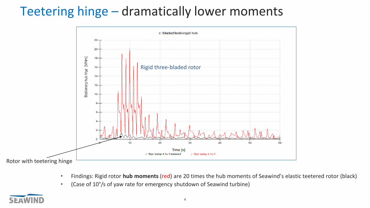
• Findings: Rigid rotor hub moments (red) are 20 times the hub moments of Seawind’s elastic teetered rotor (black)
• (Case of 10°/s of yaw rate for emergency shutdown of Seawind turbine)
Rigid three-bladed rotor
Rotor with teetering hinge
Teetering hinge – dramatically lower moments

Teetering hinge – dramatically lower fatigue values
Comparison between Seawind rotor and three-bladed NREL 5 rotor

Drivetrain „bedplate mounted“ – No vibrations
8
• No bedplate but self-sustaining stiff tubular steel nacelle body
• Drivetrain “bedplate-mounted” not shaft-mounted
• Vibration free
• Nacelle body supports strong helideck for double engine helicopters

Hinge bearing 1
Hinge Bearing 2
Hub
T shaft head
Shaft flange
Front bearing
Disk brake
Rear bearing
Coupling
Gearbox
Coupling
Air cooled squirrel cage generator
Drives
Yaw slewing bearing
Air-water heat exchanger
Hub and Nacelle – Cut-out view

Power Control – Eliminating complexity
• Low wind speeds: rotor is kept into the wind, as in three-bladers
• High wind speeds: Seawind controls power turning the turbine head out of or into the wind (yawing)
• Three-bladers control power by turning the blades around their axis (pitching)
• The blade pitch mechanism is the largest failure source in three-bladed wind turbines; Seawind eliminates this complex mechanism
SEAWIND TURBINE THREE-BLADED TURBINE
DIFFERENCES WITH 3-BLADERS
YawingPitching
10

Ability to withstand - Hurricanes (Typhoons)
• In hurricanes Seawind points blade tips into the wind in a “flexible configuration”
• Seawind’s LIDAR (laser detector) detects hurricane or strong gusts well ahead
• In Seawind 6, during hurricanes, the loads on blades and drivetrain are similar to normal operations
• Seawind’s “flexible rotor” is compliant with the forces of nature and not facing them
• Results of simulation: Seawind can withstand Category 5 hurricanes (250 km/h) without damage
• Three-bladers are parked with blades pitched at 90°, the tip chord parallel to rotor shaft, and its leading edge into wind
• Three-blader’s configuration cannot eliminate risk of major damage or total loss
• Photo: 3-bladers at Ardrossan wind farm after major storm
• Typhoon Usagi (Hong Kong, in 2013): 70% of 24 Vestas turbines damaged, 8 turbines blown off: http://goo.gl/X1jSF6
• Study: up to 50% of US offshore wind turbines would be destroyed over a 20 year period by hurricanes: http://goo.gl/gcEgDA
Wind
SEAWIND TURBINE THREE-BLADED TURBINE
DIFFERENCES
Laser (LIDAR) detects wind up to 2km ahead.
Seawind is yawed based on LIDAR information
Blade tip always kept into wind;“Flexible” rotor behaves like palm tree in storm
Wind
11

Proven design - scaled up Innovative Offshore Energy System
System Components Origin AdvantageTechnology
.Readiness Level(1 = low; 9=high)
Turbine2 Blades (1) Nasa / United Technologies Lower torque / Typhoon prone / Less Capex / Lower LCOE TRL9
Teetering Hinge (2) Nasa / Helicopter industryOvercomes gyroscopic forces / Less stress on system /
85% less Yaw Torque / Lower LCOETRL 9 (redesign)
Yaw control (3) Glidden Doman Uncomplicated control mechanism / No blade pitch control TRL 9
Controller software (4) Seawind Optimised system management TRL 7
Stiff Tubular Steel nacelle (5) Seawind Vibration free drive train / Safe access through Helideck TRL 7
Other equipment (6) Standard equipmentStandard components with longer lifetime due to lower
stressTRL 9
Foundation Self sinking concrete structure (7) Norway / Olav OlsenLow cost when industrialized / Local construction / Buoyant
system / Longer lifetime / Lower LCOETRL 9
Installation Complete assembly at harbour (8) SeawindLow cost & faster roll out/ No expensive offshore
installation vessels / Less weather dependent TRL 7
12
5Seawind design for high stiffness (patent pending). Helicopter deck itself is proven technology
6 All other equipment is 'off the shelf' equipment also used by other offshore wind solution providers
7 Numerous GBS foundations have been installed in the O&G industry in 15 - 350 m deep waters
8 Normal onshore construction industry methods
1Nasa, sponsored by DOE has built multiple 2 bladed wind turbines that have been succesfully
operated for many years
2Originating from the helicopter industry NASA adopted the technology which was further refined by
Seawind energy & helicopter engineers (https://ntrs.nasa.gov/archive/nasa/casi.ntrs.nasa.gov/19810019068.pdf)
3Glidden Doman introduced the Yaw Control succesfully at the Gamma 60 project in Italy which was
used as test facility for 6 years
4Seawind has developed the Controller software in house based on the new design, verified Seawind
simulations (prof. Bottasso TU Munich) and the Gamma 60 results

The Three Pillars - of the Revolution
• Seawind turbine: long life, low cost at sea
• Low fatigue values of system
• Safe double access by sea and air
• Maintenance and repair on board
SEAWIND TURBINE INSTALLATION OF COMPLETE UNITSCONCRETE SUPPORT STRUCTURE
• Olav Olsen concrete support structure
• Long life, low cost, when industrialized
• Installation of complete unit by sinking
• No heavy crane vessels for lifting of components needed
• Complete units launched into the sea
• Floating positioning at site
• Future: concrete transport and launching barge
13

Pillar 2: Concrete Foundations – Float-over Installation
• Seawind uses floating (floatable) concrete
foundations
• Seawind cooperates with the renowned
Norwegian company Dr. techn. Olav Olsen
on the concrete foundations
• Concrete support structure made on pier,
completed with nacelle and rotor on pier
and launched as complete unit by
sinking, no lifting!
• GBS with installation aids, removed after
sinking of the unit onto seabed
14
• Concrete Floating Foundation
• Water depth from 80 to 1000 meters and more• Anchoring with mooring lines and several types
of anchors according to seabed• Diameter 65 m• Weight of concrete structure: 7300 t • (Steel reinforcement: 1180 t)• Ballast: 3800 t (water)
Concrete Gravity Based Foundation(GBF) with installation aids (floaters)Overall weight ca. 7000 tWater depths from 30 to 70 m

The Concrete Gravity Based Foundation – Long lived
15
8m
34 m
23m62m
• The Olav Olsen GBF, cheaper, when
industrialized (serial production of
foundation families), longer life time (up
to 100 years, two turbine generations per
foundation)
• Seawind is looking with Clean-H B.V. and
cement producers into CO2-recycling for
synthetic methane (Power-to-Gas)

Pillar 3: Unique installation method – Industry benchmark
The complete system is assembled
onshore with land based cranes
not offshore with expensive vessels
……. and transported, 4 or 6 at a
time, to the wind farm location
by semi-submersible vesselsThe semi-submersible ship unloads
the units, which are installed by
temporary thrusters with GPS guide
16

Seabed – Low cost preparation and scour protection
17
Seawind has teamed up with the Norwegian subsea
operations company Scanmudring to:
• Prepare the seabed for gravity based installations
• Cable burying
• Scour protection
• Position the units at their precise location,
sinking by ballasting (water)
All operations are remote controlled

NOW 2020 2025
Seawind 6
Average
North Sea
Wind Farm*
Seawind
7
XEMC-
Darwind
Seawind
10
Industry
Target**
CAPEX(€ million/MW)
1.9 4.2 1.8 3.0 1.6 2.5-2.8
LCOE (€ cent/kWh)
0.07 0.15 0.05 0.138 0.035 0.08
Savings
* BVG Associates Offshore Wind Forecast of Future Costs and Benefits', based on 2015-2018 cost** www.gwec.net/wp-content/uploads/2016/06/160603-FINAL-Offshore-wind-cost-reduction-statement-with-annex.pdf
Seawind Economics – Superior and Robust
18
Turbine Capacity(MW)
Rotor size(meter)
Cost/MW(€ Million)
Seawind 6 6,2 126 1.9
Seawind 7 7 160 1.8
Seawind 10 10 200 1.6
Seawind Turbine Portfolio Seawind Portfolio Comparison
> 50% > 60% > 50%

Seawind demonstrator position
Demonstrator 2.0 - Test-site Metcenter
• Mean wind speed: 9.7 m/s
• Water depths 35- 40 m
• Sea bed: • - Small sand layer 1-2 m• - Compact till layer below
• Local partners for assembly, civil works, installation and O&M19
• Concrete Gravity Foundation
• Base diameter 34 m, total ballast 8200 t• Weight of concrete support structure:
4800 t for 45- 50 m water depth (steel reinforcement 700t); up to 80 m depths

Blue Alliance – Emerging set up
Strategic PartnersGlobal partners with clear motivation to enable Seawind’s technology contributing with financial and other resources to gain certain upfront rights. Blue Alliance will provide the guarantee to customers
Affiliate PartnersIndustrialization partners with distinct resources &/or relevant supply chain capabilities for Seawind’s development
Public Enablers Prepared to take a certain risk to bring innovation to the market to meet society’s needs
Regional PartnersLocal or regional stakeholders with strong connections and local know-how including relevant access to potential off-shore sites, local grid, etc. high local content(Regional Partners not shown in the graph)
Click on logo to get to partner web-site (in Slide Show mode)
20
Affiliate Partners
Regional Partners
Enova
TUM München
Metcentre
EIB
UNI
TNO Blue Allianz
Strategic Partners

42
69
8
3
81014 13
Blue Alliance plans to build out 7572 MW wind farms offshore in the following countries till 2022(*)
5
11
12
42311
12
Out of the 25372 MW to be built by 2025 by Blue Alliance 50% capacity in hurricane/typhoon areas
1
BLUE ALLIANCE – Global roll-out plan till 2025
• Order of countries / projects following actual timeline as per August 2016• Project build out can take longer than 1 year
MW MW1. Australia 150 9. Italy 150 2. Vietnam 300 10. Netherlands 700 3. Taiwan 300 11. China 6004. Philippines 372 12. India 7005. United States 900 13. Germany 5006. Greece 300 14. UK 10007. Lithuania 300 15. Japan 4008. Estonia 400 16. Poland 400
21
1675
15
15
Through installing 25372 MW Offshore:
• Seawind has 4% market share of the global Offshore capacity added in the period 2019-2025
• 64 Offshore Wind Farms are built • 50% of Seawind capacity is located in hurricane or
typhoon prone areas• 30 Million households in Europe or over twice that
number in developing countries have sustainable power• CO2 emissions are reduced by more than 50 Million t/year

Thank You
22