Embed Size (px)
Citation preview

DEFENCE DÉFENSE&
Defence Research andDevelopment Canada
Recherche et développementpour la défense Canada
Seakeeping and Operability Analysis of the
Arctic Offshore Patrol Ship with Deployed
Stabilizer Fins
Kevin McTaggart
Technical Memorandum
DRDC Atlantic TM 2012-214
October 2012
Defence R&D Canada – Atlantic
Copy No. _____

This page intentionally left blank.

Seakeeping and Operability Analysis of theArctic Offshore Patrol Ship with DeployedStabilizer FinsKevin McTaggart
Defence Research and Development Canada – AtlanticTechnical MemorandumDRDC Atlantic TM 2012-214October 2012

c© Her Majesty the Queen in Right of Canada, as represented by the Minister of NationalDefence, 2012
c© Sa Majeste la Reine (en droit du Canada), telle que representee par le ministre de laDefense nationale, 2012

Abstract
The Canadian Navy is planning to procure several Arctic Offshore Patrol Ships(AOPS), for which a design has been developed based on the Norwegian ship Sval-bard. This report presents a seakeeping analysis performed using ShipMo3D and anoperability analysis performed using SHIPOP2. To facilitate operations in ice, theAOPS design has no bilge keels; thus, roll stabilization using active stabilizer finsor internal tanks is being considered. The present analysis considers stabilizer finsdeployed in passive and active modes. Seakeeping computations indicate that rollmotions are largest in stern quartering seas at higher ship speeds, and that activestabilizer fins would provide significant roll reduction. Roll stabilization using activepumping between heeling tanks has been examined by modelling the tank systemas a ShipMo3D U-tube tank. The results indicate that active fins would be moreeffective than stabilization using heeling tanks; however, a higher fidelity model ofthe heeling tank system could yield different results. The present computations andNorwegian experience with Svalbard indicate that inclusion of active stabilizer finswould be warranted.
Resume
La Marine canadienne projette l’achat de plusieurs Navires de patrouille extracotiersde l’Arctique (NPEA), pour lesquels un modele a ete concu sur la base du navirenorvegien Svalbard. Le present rapport fournit une analyse de tenue de mer effectueea l’aide de ShipMo3D et une analyse d’operabilite effectuee a l’aide de SHIPOP2.Afin de faciliter les operations dans les glaces, le modele du NPEA ne comporte pasde quilles de roulis ; c’est pourquoi on songe a utiliser des ailerons stabilisateurs actifsou des reservoirs internes pour obtenir la stabilite en roulis. L’analyse presente traitedes ailerons stabilisateurs deployes en modes passif et actif. Les calculs de tenuede mer indiquent que les mouvements de roulis sont les plus grands dans les mersobliques arriere a des vitesses de navire plus elevees, et que des ailerons stabilisateursactifs diminueraient le roulis de facon importante. La stabilite en roulis au moyen depompage actif entre les caisses d’inclinaison a ete examinee en modelisant le systemede reservoirs en tant que reservoir a tube en U ShipMo3D. Les resultats indiquent quedes ailerons actifs seraient plus efficaces que la stabilisation par caisses d’inclinaison ;cependant, un modele plus fidele du systeme de caisses d’inclinaison pourrait donnerdes resultats differents. Les calculs actuels et l’experience norvegienne avec le Svalbardindiquent que l’integration d’ailerons stabilisateurs actifs serait justifiee.
DRDC Atlantic TM 2012-214 i

This page intentionally left blank.
ii DRDC Atlantic TM 2012-214

Executive summary
Seakeeping and Operability Analysis of the ArcticOffshore Patrol Ship with Deployed Stabilizer Fins
Kevin McTaggart; DRDC Atlantic TM 2012-214; Defence Research andDevelopment Canada – Atlantic; October 2012.
Introduction: The Canadian Navy is planning to procure several Arctic OffshorePatrol Ships (AOPS), for which a design has been developed based on the Norwegianship Svalbard. This report presents a seakeeping analysis performed using ShipMo3Dand an operability analysis performed using SHIPOP2. The analysis considers theship with stabilizer fins deployed in passive and active modes, and also considers rollstabilization using active pumping between heeling tanks.
Principal Results: Roll motions are greatest in stern quartering seas at higher shipspeeds. Roll stabilization using active fins provides significant roll reduction, and in-creases operability from 87 percent to 90 percent for operations in the North Atlantic.Roll stabilization using active pumping between heeling tanks has been examined bymodelling the tank system as a ShipMo3D U-tube tank. The present results indicatethat stabilization using heeling tanks is less effective than active fins. If stabilizationusing heeling tanks were to be seriously considered, then it is recommended that amore sophisticated model of the heeling tank system be developed.
Significance of Results: The analysis suggests that AOPS should include activestabilizer fins. This finding is consistent with Norwegian experience with the Svalbard,which was retrofitted with stabilizer fins. The predicted 3 percent increase in shipoperability could be used to support an economic argument for including stabilizerfins.
Future Plans: Implementation of active tank stabilization systems will be consid-ered for future releases of ShipMo3D.
DRDC Atlantic TM 2012-214 iii

Sommaire
Seakeeping and Operability Analysis of the ArcticOffshore Patrol Ship with Deployed Stabilizer Fins
Kevin McTaggart ; DRDC Atlantic TM 2012-214 ; Recherche et developpementpour la defense Canada – Atlantique ; octobre 2012.
Introduction : La Marine canadienne projette l’achat de plusieurs Navires de pa-trouille extracotiers de l’Arctique (NPEA), pour lesquels un modele a ete concu surla base du navire norvegien Svalbard. Le present rapport fournit une analyse de tenuede mer effectuee a l’aide de ShipMo3D et une analyse d’operabilite effectuee a l’aidede SHIPOP2. L’analyse presente traite des ailerons stabilisateurs deployes en modespassif et actif, et examine egalement la stabilite en roulis au moyen de pompage actifentre les caisses d’inclinaison.
Resultats principaux : Les mouvements de roulis sont les plus grands dans les mersobliques arriere a des vitesses de navire plus elevees. La stabilite en roulis a l’aided’ailerons stabilisateurs actifs diminue le roulis de facon importante, et augmente l’ex-ploitabilite de 87 a 90 pourcent pour les operations dans l’Atlantique Nord. La sta-bilite en roulis au moyen de pompage actif entre les caisses d’inclinaison a egalementete examinee en modelisant le systeme de reservoirs en tant que reservoir a tube en UShipMo3D. Les resultats actuels indiquent que la stabilisation par caisses d’inclinai-son est moins efficace que la stabilisation par ailerons actifs. Si on devait considererserieusement la stabilisation a l’aide de caisses d’inclinaison, on recommande alorsd’elaborer un modele plus sophistique de systeme de caisses d’inclinaison.
Importance des resultats : L’analyse suggere que le NPEA devrait avoir des aile-rons stabilisateurs actifs. Cette constatation correspond aux constatations issues del’experience norvegienne avec le Svalbard, qui a ete modifie pour integrer des aileronsstabilisateurs. L’augmentation prevue de 3 pourcent de la capacite operationnelledes navires pourrait servir en guise d’argument economique en vue de l’integrationd’ailerons stabilisateurs.
Travaux ulterieurs prevus : L’integration de systemes de stabilisation de reservoirsactifs sera envisagee pour les prochaines versions du ShipMo3D.
iv DRDC Atlantic TM 2012-214

Table of contents
Abstract . . . . . . . . . . . . . . . . . . . . . . . . . . . . . . . . . . . . . . . i
Resume . . . . . . . . . . . . . . . . . . . . . . . . . . . . . . . . . . . . . . . i
Executive summary . . . . . . . . . . . . . . . . . . . . . . . . . . . . . . . . . iii
Sommaire . . . . . . . . . . . . . . . . . . . . . . . . . . . . . . . . . . . . . . iv
Table of contents . . . . . . . . . . . . . . . . . . . . . . . . . . . . . . . . . . v
List of figures . . . . . . . . . . . . . . . . . . . . . . . . . . . . . . . . . . . . vi
List of tables . . . . . . . . . . . . . . . . . . . . . . . . . . . . . . . . . . . . viii
1 Introduction . . . . . . . . . . . . . . . . . . . . . . . . . . . . . . . . . . . 1
2 ShipMo3D Model for Seakeeping Analysis . . . . . . . . . . . . . . . . . . 1
3 Roll and Pitch Motions in Waves . . . . . . . . . . . . . . . . . . . . . . . 5
4 Roll Stabilization Using Active Control of Heeling Tanks . . . . . . . . . . 9
5 Operability Analysis . . . . . . . . . . . . . . . . . . . . . . . . . . . . . . 13
6 Discussion . . . . . . . . . . . . . . . . . . . . . . . . . . . . . . . . . . . . 17
7 Conclusions . . . . . . . . . . . . . . . . . . . . . . . . . . . . . . . . . . . 17
References . . . . . . . . . . . . . . . . . . . . . . . . . . . . . . . . . . . . . . 19
Symbols and Abbreviations . . . . . . . . . . . . . . . . . . . . . . . . . . . . 20
DRDC Atlantic TM 2012-214 v

List of figures
Figure 1: General Arrangement of Arctic Offshore Patrol Ship . . . . . . . . 2
Figure 2: Profile View of Rhino3D Hull Form Model of Arctic OffshorePatrol Ship . . . . . . . . . . . . . . . . . . . . . . . . . . . . . . 3
Figure 3: Profile View of Rhino3D Hull Form Model of Arctic OffshorePatrol Ship . . . . . . . . . . . . . . . . . . . . . . . . . . . . . . 3
Figure 4: Lower Aft View of ShipMo3D AOPS Model . . . . . . . . . . . . 4
Figure 5: RMS Roll Motions in Sea State 5, Significant Wave Height Hs =3.25 m, Peak Wave Period Tp = 9.7 s, Passive and ActiveStabilizer Fins . . . . . . . . . . . . . . . . . . . . . . . . . . . . . 6
Figure 6: RMS Pitch Motions in Sea State 5, Significant Wave Height Hs =3.25 m, Peak Wave Period Tp = 9.7 s . . . . . . . . . . . . . . . . 6
Figure 7: RMS Roll Motions in Sea State 6, Significant Wave Height Hs =5.0 m, Peak Wave Period Tp = 12.4 s, Passive and ActiveStabilizer Fins . . . . . . . . . . . . . . . . . . . . . . . . . . . . . 7
Figure 8: RMS Pitch Motions in Sea State 6, Significant Wave Height Hs =5.0 m, Peak Wave Period Tp = 12.4 s . . . . . . . . . . . . . . . . 7
Figure 9: RMS Roll Motions in Sea State 7, Significant Wave Height Hs =7.5 m, Peak Wave Period Tp = 15.0 s, Passive and ActiveStabilizer Fins . . . . . . . . . . . . . . . . . . . . . . . . . . . . . 8
Figure 10: RMS Pitch Motions in Sea State 7, Significant Wave Height Hs =7.5 m, Peak Wave Period Tp = 15.0 s . . . . . . . . . . . . . . . . 8
Figure 11: Heeling Tanks . . . . . . . . . . . . . . . . . . . . . . . . . . . . . 10
Figure 12: U-tube Tank Model of Heeling Tanks for Roll Stabilization . . . . 10
Figure 13: RMS Roll Motions in Sea State 5, Significant Wave Height Hs =3.25 m, Peak Wave Period Tp = 9.7 s, Passive Fins, Influence ofActive Heeling Tanks . . . . . . . . . . . . . . . . . . . . . . . . . 11
Figure 14: RMS Roll Motions in Sea State 6, Significant Wave Height Hs =5.0 m, Peak Wave Period Tp = 12.4 s, Passive Fins, Influence ofActive Heeling Tanks . . . . . . . . . . . . . . . . . . . . . . . . . 11
vi DRDC Atlantic TM 2012-214

Figure 15: RMS Roll Motions in Sea State 7, Significant Wave Height Hs =7.5 m, Peak Wave Period Tp = 15.0 s, Passive Fins, Influence ofActive Heeling Tanks . . . . . . . . . . . . . . . . . . . . . . . . . 12
Figure 16: Speed Distribution for Operability Analysis . . . . . . . . . . . . . 14
Figure 17: Relative Sea Direction Distribution for Operability Analysis . . . 14
Figure 18: Percent Time Operable Versus Ship Speed for Transit Mission inNorth Atlantic . . . . . . . . . . . . . . . . . . . . . . . . . . . . . 15
Figure 19: Percent Time Operable Versus Relative Sea Direction for TransitMission in North Atlantic, Ship Speed 6 knots . . . . . . . . . . . 16
Figure 20: Percent Time Operable Versus Relative Sea Direction for TransitMission in North Atlantic, Ship Speed 12 knots . . . . . . . . . . 16
DRDC Atlantic TM 2012-214 vii

List of tables
Table 1: Arctic Offshore Patrol Ship Dimensions, Light OperatingDeparture Condition at Beginning of Service Life . . . . . . . . . 2
Table 2: Stabilizer Fin Control Parameters . . . . . . . . . . . . . . . . . . 5
Table 3: Operability Criteria for Transit Mission . . . . . . . . . . . . . . . 13
Table 4: Percent Time Operable for Transit Mission in North Atlantic . . . 15
viii DRDC Atlantic TM 2012-214

1 Introduction
The Canadian Navy is planning to procure several Arctic Offshore Patrol Ships(AOPS). The AOPS design is based on the Norwegian icebreaker and patrol shipSvalbard, and has a displacement of approximately 5300 tonnes.
In response to a request from the AOPS Project Management Office (PMO), DRDCAtlantic has performed a seakeeping and operability analysis using the ShipMo3Dship motion suite [1, 2] and the ship operability program SHIPOP [3]. Section 2describes development of the AOPS ShipMo3D model, with predicted roll and pitchmotions shown in Section 3 for stabilizer fins in passive and active modes. Section 4examines utilization of heeling tanks for roll stabilization. An operability analysis forthe ship with passive and active stabilizer fins is given in Section 5. Section 6 discussesgeneral results, and is followed by final conclusions in Section 7.
2 ShipMo3D Model for Seakeeping Analysis
The program SHIPMO7 [4] and applications within the ShipMo3D suite [1, 2] areroutinely used for seakeeping analysis of ships within the Canadian Navy. SHIPMO7is based on strip theory, which is most suited for slender vessels (e.g., length to beamratio L/B > 6). In contrast, ShipMo3D is based on three-dimensional hydrodynamiccomputations and can be used for non-slender vessels. Given that AOPS is a non-slender vessel (L/B = 4.4), ShipMo3D is used for the present analysis. Version 2[1, 2] is the current release version of ShipMo3D; however, it was decided to use apre-release version of ShipMo3D 3 because it includes the following capabilities:
• modelling of U-tube tanks, which could be used to model roll stabilization usingheeling tanks,
• writing of response amplitude operators (RAOs) to a post-processing file thatcan be used for operability analysis by SHIPOP2 [3].
The ShipMo3D model was developed from design data produced by STX CanadaMarine. Figure 1 shows the general arrangement of the ship. Figures 2 and 3 showprofile and lower aft views of the hull geometry model as shown by the 3D geometricmodelling program Rhinoceros, also known as Rhino3D [5]. Rhino3D is widely usedwithin the field of naval architecture design.
Table 1 gives dimensions for AOPS, including the load condition used for the presentstudy. The light operating condition at beginning of service life was used for thepresent study because it is considered representative of a lighter operational condition,which could have somewhat greater motions than for a heavier operational condition.
DRDC Atlantic TM 2012-214 1
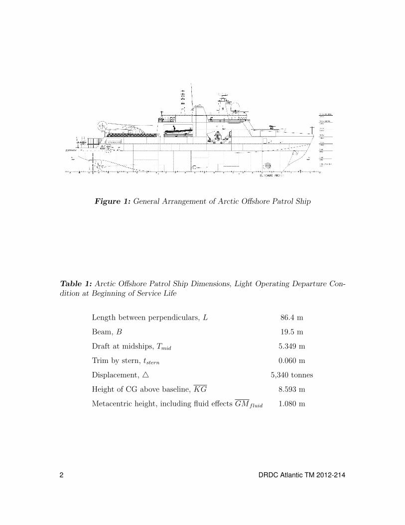
Figure 1: General Arrangement of Arctic Offshore Patrol Ship
Table 1: Arctic Offshore Patrol Ship Dimensions, Light Operating Departure Con-dition at Beginning of Service Life
Length between perpendiculars, L 86.4 m
Beam, B 19.5 m
Draft at midships, Tmid 5.349 m
Trim by stern, tstern 0.060 m
Displacement, 4 5,340 tonnes
Height of CG above baseline, KG 8.593 m
Metacentric height, including fluid effects GM fluid 1.080 m
2 DRDC Atlantic TM 2012-214

Figure 2: Profile View of Rhino3D Hull Form Model of Arctic Offshore Patrol Ship
Figure 3: Profile View of Rhino3D Hull Form Model of Arctic Offshore Patrol Ship
DRDC Atlantic TM 2012-214 3

When preparing a ShipMo3D ship model, the most time consuming part is usuallythe preparation of the input hull lines. A new computer program SM3DRhinoTo-PatchHull was developed to determine input ShipMo3D hull lines from the AOPSRhino3D model. SM3DRhinoToPatchHull uses the Rhino DotNET software library,which comes with the Rhino3D application software. The Grasshopper Primer [6] pro-vided useful Rhino3D reference information when using the Rhino DotNET softwarelibrary. Grass-hopper is one of several applications available based on Rhino3D.
Figure 4 shows the ShipMo3D model of the ship. The ShipMo3D model includes thewet hull, dry hull, rudders, propellers, skegs, and stabilizer fins. To simplify modellingof the hull, the molded skegs are modelled as appended skegs. To facilitate operationsin ice, the AOPS design has no bilge keels.
Figure 4: Lower Aft View of ShipMo3D AOPS Model
The ShipMo3D model includes roll stabilizer fins, which can be in passive or activemodes for ship motion computations. When active, the stabilizer fins respond to aninput command deflection angle as follows:
δfin + 2 ζδ ωδ δfin + ω2
δ δfin = ω2
δ δfinC (1)
where δfin is deflection acceleration, ζδ is deflection damping, ωδ is deflection naturalfrequency, δfin is deflection velocity, and δfin is deflection angle. The command finangle δfinC is dependent upon input gains as follows:
δfinC =6∑j=1
[kPδj
(ηfj − η
fCj
)+ kIδj
∫ τfinmax
0
(ηfj (t− τ)− ηfCj
)dτ + kDδj η
fj
](2)
4 DRDC Atlantic TM 2012-214

where kPδj is proportional gain for motion mode j, ηfj is ship motion displacement
in earth-fixed coordinates for mode j, kIδj is integral gain, τ finmax is maximum delay
time for evaluating integral gain response, ηfCj is command displacement for mode j,
and kDδj is velocity gain. Table 2 shows the stabilizer fin control parameters. The rollvelocity gain value of −10 s causes the stabilizer fins to supplement the roll dampingof the ship. The magnitude of the gain was selected such that RMS deflection ofthe stabilizer fins would typically be less than 10 degrees, with maximum deflectionangles less than the 35 degree limits of the fins. To obtain improved roll stabilization,the roll velocity gain could be adjusted for each combination of seaway, ship speed,and ship heading.
Table 2: Stabilizer Fin Control Parameters
Maximum deflection angle, δfinmax 35 deg
Maximum deflection rate, δfinmax 10 deg/s
Deflection natural frequency, ωδ 3 rad/s
Deflection damping (fraction of critical) ζδ 0.85
Roll velocity gain (when active), kPδ4 −10 s
3 Roll and Pitch Motions in Waves
Figures 5 to 10 show roll and pitch motions in sea states 5, 6, and 7 for ship speeds of 6and 12 knots. The roll results include values for both passive and active roll stabilizerfins. The most noticeable feature of the ship motions is the high roll response in sternquartering seas when travelling at 12 knots with passive fins. Under these conditions,the wave encounter period approximates the ship natural roll period of 15.6 s. Due tothe higher ship speed associated with large roll motions, active stabilizer fins can bevery effective in suppressing roll motions. The pitch motions are typical for a vesselof its size.
DRDC Atlantic TM 2012-214 5

0 30 60 90 120 150 180
Relative sea direction βs
0
1
2
3
4R
MS
roll
(deg
)
............................................
............................................
......................................................
....................................................................
....................................................................................................................................................................................................................................................................................................................................................................................................................................................................................................................................................................................................................................................................................................................................................................... ............. ............. ............. ............. ............. ............. ............. ............. ............. ............. ............. ............. ............. ............. ............. ............. ............. ............. ............. ............. ............. ............. ............. ............. ............. ............. ............. ............. ............. ............. ............. ............. ............. ............. ............. .............................
...................................................................................................................................................................................................................................................................................................................................................................................................................................................................................................................................................................................................................................................................................................................................................................................................................................................................................................................................................................................................................................................................................................................................................................................................................................................................................................................................................................................................
..........................
..........................
..........................
.......................... ............. ............. ............. ............. ............. ............. ............. ............. ............. ............. ............. ............. ............. ............. ............. ............. ............. ............. ............. ............. ............. ............. ............. ............. ............. ............. ............. ............. ............. .............
......................................................... 6 knots, passive fins
............. ............. ....... 6 knots, active fins
......................................................... 12 knots, passive fins
............. ............. ....... 12 knots, active fins
Figure 5: RMS Roll Motions in Sea State 5, Significant Wave Height Hs = 3.25 m,Peak Wave Period Tp = 9.7 s, Passive and Active Stabilizer Fins
0 30 60 90 120 150 180
Relative sea direction βs
0.0
0.5
1.0
1.5
2.0
RM
Spi
tch
(deg
)
..........................................................................................................................................................................................................................................................................................................................................................................................................................................................................................................................................................................................................
...................................................................................................................................................................................................................................................................................................
..............................................................
........................................................................................................................................................................................................................................
..........................................................................................................................................................................................................................................................................................................................................................................................................................................................................................................................................................................
..................................................................................................................................................................................................................................................................................
..........................................................
..................................................................................................................................................................................................................................
............
......................................................... 6 knots, passive fins
......................................................... 12 knots, passive fins
Figure 6: RMS Pitch Motions in Sea State 5, Significant Wave Height Hs = 3.25 m,Peak Wave Period Tp = 9.7 s
6 DRDC Atlantic TM 2012-214

0 30 60 90 120 150 180
Relative sea direction βs
0
2
4
6R
MS
roll
(deg
)
....................................................................................................................................................
..........................................
..........................................
...........................................................
.................................................................................................................................................................................................................................................................................................................................................................................................................................................................................................................................................................................................................................................................................................................................................................................
..........................
..........................
............. ............. ............. ............. ............. ............. ............. ............. ............. ............. ............. ............. ............. ............. ............. ............. ............. ............. ............. ............. ............. ............. ............. ............. ............. ............. ............. ............. ............. ............. ............. ............. ............. ..................................................................................................................................................................................................................................................................................................................................................................................................................................................................................................................
.........................................................................................................................................................................................................................................................................................................................................................................................................................................................................................................................................................................................................................................................................................................................................................................................................................................................................................................................
..........................
..........................
..........................
............. ............. ............. ............. ............. ............. ............. ............. ............. ............. ............. ............. ............. ............. ............. ............. ............. ............. ............. ............. ............. ............. ............. ............. ............. ............. ............. ............. ............. ............. .............
......................................................... 6 knots, passive fins
............. ............. ....... 6 knots, active fins
......................................................... 12 knots, passive fins
............. ............. ....... 12 knots, active fins
Figure 7: RMS Roll Motions in Sea State 6, Significant Wave Height Hs = 5.0 m,Peak Wave Period Tp = 12.4 s, Passive and Active Stabilizer Fins
0 30 60 90 120 150 180
Relative sea direction βs
0
1
2
3
RM
Spi
tch
(deg
)
...................................................................................................................................................................................................................................................................................................................................................................................................................................................................................................................................................................................................................................................................................................................................................................................................................................................
..................................................
..................................................................................
................................................................................................................................................................
......................................................................................................................................................................................................................................................................................................................................................................................................................................................................................................................................................................................................................................................................................................................................................................................................
..................................................
..............................................................
....................................................................................................
....................................................................................................
......................................................... 6 knots, passive fins
......................................................... 12 knots, passive fins
Figure 8: RMS Pitch Motions in Sea State 6, Significant Wave Height Hs = 5.0 m,Peak Wave Period Tp = 12.4 s
DRDC Atlantic TM 2012-214 7

0 30 60 90 120 150 180
Relative sea direction βs
0
2
4
6
8R
MS
roll
(deg
)
...........................................................................................................................................................................................................................................................................
............................................
...............................................
....................................................................
.............................................................................................................................................................................................................................................................................................................................................................................................................................................................................................................................................................................................................................................................................................................................................
..........................
..........................
..........................
............. ............. ............. ............. ............. ............. ............. ............. ............. ............. ............. ............. ............. ............. ............. ............. ............. ............. ............. ............. ............. ............. ............. ............. ............. ............. ............. ............. ............. ............. ............. ..............................................................................................................................................................................................................................................................................................................................................................................................................................................................
....................................................
...........................................................................................................................................................................................................................................................................................................................................................................................................................................................................................................................................................................................................................................................................................................................................................................................................................................................................................
..........................
..........................
..........................
............. ............. ............. ............. ............. ............. ............. ............. ............. ............. ............. ............. ............. ............. ............. ............. ............. ............. ............. ............. ............. ............. ............. ............. ............. ............. ............. ............. ............. ............. .............
......................................................... 6 knots, passive fins
............. ............. ....... 6 knots, active fins
......................................................... 12 knots, passive fins
............. ............. ....... 12 knots, active fins
Figure 9: RMS Roll Motions in Sea State 7, Significant Wave Height Hs = 7.5 m,Peak Wave Period Tp = 15.0 s, Passive and Active Stabilizer Fins
0 30 60 90 120 150 180
Relative sea direction βs
0
1
2
3
RM
Spi
tch
(deg
)
..................................................................................................................................................................................................................................................................................................................................................................................................................................................................................................................................................................................................................................................................................................................................................................................................................................................................................................
............................................
...................................................
..............................................................
.......................................................................................................................
..................................
.............................................................................................................................................................................................................................................................................................................................................................................................................................................................................................................................................................................................................................................................................................................................................................................................................................................................
..........................................
...........................................
........................................................
...................................................................
....................................................................................................................
......................................................... 6 knots, passive fins
......................................................... 12 knots, passive fins
Figure 10: RMS Pitch Motions in Sea State 7, Significant Wave Height Hs = 7.5 m,Peak Wave Period Tp = 15.0 s
8 DRDC Atlantic TM 2012-214

4 Roll Stabilization Using Active Control ofHeeling Tanks
The AOPS design includes heeling tanks, which are intended for producing roll mo-ments when required during operations in ice. The heeling tanks could possibly beused for roll stabilization in waves through active pumping of water between tanks.ShipMo3D has no capability for modelling active pumping of water between tanks;however, a new capability within ShipMo3D for simulating U-tube tanks was used tomodel roll stabilization using the heeling tanks. Figure 11 shows the heeling tanks,which are located at station 6.67 and have lengths of 6.4 m along the ship longitudi-nal axis. Each tank has a volume of 87.8 m3. Figure 12 shows the equivalent U-tubetank model of the heeling tanks. Simulation of U-tube tanks within ShipMo3D isbased on the work of Lloyd [7]. The U-tube tank model has the same total volume asthe heeling tanks, and the fluid displacement natural frequency is set approximatelyequal to the ship roll natural frequency to provide optimal damping of roll resonance.The U-tube tank dimensions were determined using the following steps:
• The length of the U-tube tank along the ship longitudinal axis was set to 6.4 m,matching the length of the heeling tanks.
• The height of each reservoir was set to 6 m, the same as the total height of eachheeling tank.
• The width of each reservoir was set to 2.28 m based on total volume of eachheeling tank.
• The lateral distance between reservoir centres was set to 14 m based on theheeling tank spacing.
• The height of the duct between reservoirs was set to 0.21 m to obtain a fluidmotion natural frequency of 0.35 rad/s, approximating the ship roll naturalfrequency.
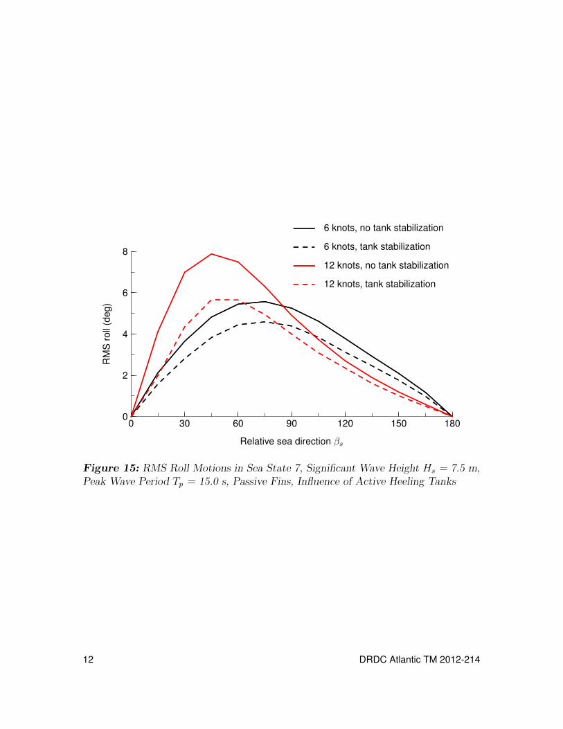
Figures 13 to 15 show roll motions without stabilization and with stabilization usingthe heeling tanks modelled as a U-tube tank. The stabilizer fins are passive in allcases. In most cases, tank stabilization gives some reduction of roll motions, withmotion reductions typically being greatest when roll motions are large. Overall, theroll motion reductions predicted using tank stabilization are relatively modest. Iftank stabilization were to be seriously considered, then it is recommended that amodel of active tank stabilization using pumps be developed. The limited predictedeffectiveness using the heeling tanks might be partly due to the low vertical elevationof the tanks within the ship. For U-tube tanks, effectiveness typically increases withvertical elevation, and this might also be applicable for active stabilization using theheeling tanks.
DRDC Atlantic TM 2012-214 9

................................................................................................................................................................................................................
..........................................................
.........................................................................................................................................................................................................................................................................................................................................................................................................................................................................................
................................................................................................................................................................................................................
..........................................................
.................................................
...........................................
.............................................................................................................................................................................................................................................................................................................................................................................................
..............................................................................................................................................................................................................................................................................
..................
..................
..................
..................
..................
.............................................................................
Figure 11: Heeling Tanks
................................................................................................................................................................................................................
..........................................................
.........................................................................................................................................................................................................................................................................................................................................................................................................................................................................................
................................................................................................................................................................................................................
..........................................................
.................................................
...........................................
.............................................................................................................................................................................................................................................................................................................................................................................................
................................................................................................................................................................................................................................................................................................................................................................................................................................................................................................................................................................................................................................................................................................................................................................................................................................................................................................................................................................................................................................................ .................................................................................................................................................................................................................................................................................................................................................................................................................................................................................................................................................................................................................................................................
..................
..................
..................
..................
..................
..................
..................
..................
..................
..................
........
....................................................................................................................................................................
.
.
.
.
.
.
.
.
.
.
.
.
.
.
.
.
.
.
.
.
.
.
.
.
.
.
.
.
.
.
.
.
.
.
.
.
.
.
.
.
.
.
.
.
.
.
.
.
.
.
.
.
.
.
.
.
.
.
.
.
.
.
.
.
.
.
.
.
.
.
.
.
.
.
.
.
.
.
.
.
.
.
.
.
.
.
.
.
.
.
.
.
.
.
.
.
.
.
.
.
.
.
.
.
.
.
.
.
.
.
.
.
.
.
.
.
.
.
.
.
.
.
.
.
.
.
.
.
.
.
.
.
.
.
.
.
.
.
.
.
.
.
.
.
.
.
.
.
.
.
.
.
.
.
.
.
.
.
.
.
.
.
.
.
.
.
.
.
.
.
.
.
.
.
.
.
.
.
.
.
.
.
.
.
.
.
.
.
.
.
.
.
.
.
.
.
.
.
.
.
.
.
.
.
.
.
.
.
.
.
.
.
.
.
.
.
.
.
.
.
.
.
.
.
.
.
.
.
.
.
.
.
.
.
.
.
.
.
.
.
.
.
.
.
.
.
.
.
.
.
.
.
.
.
.
.
.
.
.
.
.
.
.
.
.
.
.
.
.
.
.
.
.
.
.
.
.
.
.
.
.
.
.
.
.
.
.
.
.
.
.
.
.
.
.
.
.
.
.
.
.
.
.
.
.
.
.
.
.
.
.
.
.
.
.
.
.
.
.
.
.
.
.
.
.
.
.
.
.
.
.
.
.
.
.
.
.
.
.
.
.
.
.
.
.
.
.
.
.
.
.
.
. . . . . . . . . . . . . . . . . . . . . . . . . . . . . . . . . . . . . . . . .
Figure 12: U-tube Tank Model of Heeling Tanks for Roll Stabilization
10 DRDC Atlantic TM 2012-214

0 30 60 90 120 150 180
Relative sea direction βs
0
1
2
3
4
RM
Sro
ll(d
eg)
............................................
............................................
......................................................
....................................................................
.......................................................................................................................................................................................................................................................................................................................................................................................................................................................................................................................................................................................................................................................................................................................................................................
..........................
..........................
............. ............. ............. ............. ............. ............. ............. ............. ............. ............. ............. ............. ............. ............. ............. ............. ............. ............. ............. ............. ............. ............. ............. ............. ............. ............. ............. ............. ............. ............. ............. ............. ............. ........................................................................................................................................................................................................................................................................................................................................................................................................................................................................................................................................................................................................................................................................................................................................................................................................................................................................................................................................................................................................................................................................................................................................................................................................................................................................................................................................................................................................................
......................................................................................................................................................................................
............. ............. ............. ............. ............. ............. ............. .............................................................................. ............. ............. ............. ............. ............. ............. ............. ............. ............. ............. ............. ............. ............. ............. ............. ............. ............. ............. ............. ............. ............. ............
......................................................... 6 knots, no tank stabilization
............. ............. ....... 6 knots, tank stabilization
......................................................... 12 knots, no tank stabilization
............. ............. ....... 12 knots, tank stabilization
Figure 13: RMS Roll Motions in Sea State 5, Significant Wave Height Hs = 3.25 m,Peak Wave Period Tp = 9.7 s, Passive Fins, Influence of Active Heeling Tanks
0 30 60 90 120 150 180
Relative sea direction βs
0
2
4
6
RM
Sro
ll(d
eg)
....................................................................................................................................................
..........................................
..........................................
...........................................................
.................................................................................................................................................................................................................................................................................................................................................................................................................................................................................................................................................................................................................................................................................................................................................................................
..........................
..........................
..........................
..........................
............. ............. ............. ............. ............. ............. ............. ............. ............. ............. ............. ............. ............. ............. ............. ............. ............. ............. ............. ............. ............. ............. ............. ............. ............. ............. ............. ............. ............. ............. ............. ......................................................................................................................................................................................................................................................................................................................................................................................................................................................................................................................
.........................................................................................................................................................................................................................................................................................................................................................................................................................................................................................................................................................................................................................................................................................................................................................................................................................................................................................................................
..........................
.....................................................................................................................
..........................
.......................... ............. ............. ............. ............. ............. ............. ............. ............. ............. ............. ............. ............. ............. ............. ............. ............. ............. ............. ............. ............. ............. ............. ............. ............. ............. ............. ............. ............. ............. .............
......................................................... 6 knots, no tank stabilization
............. ............. ....... 6 knots, tank stabilization
......................................................... 12 knots, no tank stabilization
............. ............. ....... 12 knots, tank stabilization
Figure 14: RMS Roll Motions in Sea State 6, Significant Wave Height Hs = 5.0 m,Peak Wave Period Tp = 12.4 s, Passive Fins, Influence of Active Heeling Tanks
DRDC Atlantic TM 2012-214 11
0 30 60 90 120 150 180
Relative sea direction βs
0
2
4
6
8
RM
Sro
ll(d
eg)
...........................................................................................................................................................................................................................................................................
............................................
...............................................
....................................................................
.............................................................................................................................................................................................................................................................................................................................................................................................................................................................................................................................................................................................................................................................................................................................................
..........................
..........................
..........................
..........................
..........................
............. ............. ............. ............. ............. ............. ............. ............. ............. ............. ............. ............. ............. ............. ............. ............. ............. ............. ............. ............. ............. ............. ............. ............. ............. ............. ............. ............. ............. ..............................................................................................................................................................................................................................................................................................................................................................................................................................................................
....................................................
...........................................................................................................................................................................................................................................................................................................................................................................................................................................................................................................................................................................................................................................................................................................................................................................................................................................................................................
..........................
........................................................................................................
..........................
.......................... ............. ............. ............. ............. ............. ............. ............. ............. ............. ............. ............. ............. ............. ............. ............. ............. ............. ............. ............. ............. ............. ............. ............. ............. ............. ............. ............. ............. ............. ....
......................................................... 6 knots, no tank stabilization
............. ............. ....... 6 knots, tank stabilization
......................................................... 12 knots, no tank stabilization
............. ............. ....... 12 knots, tank stabilization
Figure 15: RMS Roll Motions in Sea State 7, Significant Wave Height Hs = 7.5 m,Peak Wave Period Tp = 15.0 s, Passive Fins, Influence of Active Heeling Tanks
12 DRDC Atlantic TM 2012-214

5 Operability Analysis
An operability analysis was performed using SHIPOP2 [3] to examine percent timeoperable (PTO) for ship operations in the North Atlantic. An operability analysisevaluates the percentage of time that a ship meets specified operability criteria whenoperating in a given environment. Table 3 gives the operability criteria, which arebased on recommended values for a transit mission in the NATO seakeeping standard[8]. The ship is assumed to operate in the annual North Atlantic wave environmentfrom Bales, Lee, and Voelker [9], which is used by NATO [10]. The distribution ofspeeds in Figure 16 is based on data provided by the AOPS Project ManagementOffice. Relative sea directions are assumed to have a uniform distribution, and arediscretized as shown in Table 17. A relative sea direction βs of 180 degrees representshead seas.
Table 3: Operability Criteria for Transit Mission
RMS roll 4.0◦
RMS pitch 1.5◦
RMS vertical acceleration at bridge 0.2 g
RMS lateral acceleration at bridge 0.1 g
Tipping motion-induced interruptions at bridge 1.0 per minute
RMS vertical acceleration at flight deck 0.2 g
RMS lateral acceleration at flight deck 0.1 g
Tipping motion-induced interruptions at flight deck 1.0 per minute
Wetness rate at fore deck 30 per hour
Slamming rate at station 3 20 per hour
Emergence rate for top quarter of propellers 90 per hour
Table 4 and Figures 18 to 20 give results of the operability analysis. The ship hashigh operability, as would be expected for a vessel of its size. Activation of stabilizerfins increases operability from 87 percent to 90 percent. The increase in operabilitydue to active fins could be enhanced by optimization of fin gains for each combinationof wave conditions, ship speed, and relative sea direction. Figure 18 illustrates thatactive fins have a greater influence at higher ship speeds, which is due to both higherroll motions and higher fin stabilization forces at higher speeds. Figures 19 and 20show variation of percent time operable with relative sea direction for ship speeds of
DRDC Atlantic TM 2012-214 13

3 6 9 12 14
Ship speed Vs (knots)
0
5
10
15
20
25Pe
rcen
ttim
e
Figure 16: Speed Distribution for Operability Analysis
0 30 60 90 120 150 180
Relative sea direction βs (deg)
0
5
10
Perc
entt
ime
Figure 17: Relative Sea Direction Distribution for Operability Analysis
14 DRDC Atlantic TM 2012-214

6 and 12 knots. Active fins give a significant increase in operability at higher speedsin stern quartering seas. Lower operability in head and bow quartering seas is causedmostly be pitch motions and motion-induced interruptions at the bridge.
Table 4: Percent Time Operable for Transit Mission in North Atlantic
Passive stabilizer fins 87 percent
Active stabilizer fins 90 percent
3 6 9 12 14
Ship speed Vs (knots)
0
20
40
60
80
100
Perc
entt
ime
oper
able
Passive fins Active fins
Figure 18: Percent Time Operable Versus Ship Speed for Transit Mission in NorthAtlantic
DRDC Atlantic TM 2012-214 15

0 30 60 90 120 150 180
Relative sea direction βs (deg)
0
20
40
60
80
100Pe
rcen
ttim
eop
erab
lePassive fins Active fins
Figure 19: Percent Time Operable Versus Relative Sea Direction for Transit Missionin North Atlantic, Ship Speed 6 knots
0 30 60 90 120 150 180
Relative sea direction βs (deg)
0
20
40
60
80
100
Perc
entt
ime
oper
able
Passive fins Active fins
Figure 20: Percent Time Operable Versus Relative Sea Direction for Transit Missionin North Atlantic, Ship Speed 12 knots
16 DRDC Atlantic TM 2012-214

6 Discussion
The design is based on the existing Norwegian ship Svalbard, which mitigates riskregarding seakeeping performance. For the Canadian Navy, the primary decisionsinfluencing AOPS seakeeping performance will be related to roll stabilization. Thepresent seakeeping and operability analysis indicates that active stabilizer fins wouldsignificantly enhance performance. When considering economic benefit, it could beargued that a 3 percent increase in operability could justify spending on active stabi-lizer fins, which would be less than 3 percent of total ship cost. For the Norwegian shipSvalbard, stabilizer fins were retrofitted after initial operation without fins. Incorpo-ration of stabilizer fins into the original design and construction for AOPS would bemore cost effective than a subsequent retrofit.
Active pumping between heel tanks is another option that could be used for rollstabilization. For the present study this option has been approximated using a U-tubetank model. A more rigourous analysis could be performed by developing a detailedmodel of active pumping between heel tanks. An advantage of tank stabilizationrelative to fin stabilization is that it is effective at low speeds, including zero speed.For the AOPS design, this is not a major advantage because the natural roll periodof the ship is relatively large (15.6 s), and large roll motions tend to be limited towhen the ship is travelling at higher speeds in stern quartering seas.
7 Conclusions
A seakeeping and operability analysis for the Arctic Offshore Patrol Ship has beenperformed for the ship with stabilizer fins deployed in passive and active modes.Roll motions are greatest in stern quartering seas when travelling at higher speeds,and could be significantly reduced by active stabilizer fins. Active roll stabilization bypumping water between heeling tanks has been modelled by approximating the systemas a U-tube tank. Predictions indicate that stabilizer fins would be more effective thanactive pumping between heeling tanks. If roll stabilization using pumping betweenheeling tanks were to be considered further, then it is recommended that a moresophisticated model of the system physics be developed.
DRDC Atlantic TM 2012-214 17

This page intentionally left blank.
18 DRDC Atlantic TM 2012-214

References
[1] McTaggart, K. (2010), ShipMo3D Version 2.0 User Manual for SimulatingMotions of a Freely Maneuvering Ship in a Seaway, (DRDC Atlantic TM2010-131) Defence Research and Development Canada - Atlantic.
[2] McTaggart, K. (2010), ShipMo3D Version 2.0 User Manual for FrequencyDomain Analysis of Ship Seakeeping in a Seaway, (DRDC Atlantic TM2010-132) Defence Research and Development Canada - Atlantic.
[3] McTaggart, K. (2000), SHIPOP2: An Updated Program for Computing ShipOperability in Waves and Wind, (DREA TM 2000-138) Defence ResearchEstablishment Atlantic.
[4] McTaggart, K. (1997), SHIPMO7: An Updated Strip Theory Program forPredicting Ship Motions and Sea Loads in Waves, (DREA TM 96/243) DefenceResearch Establishment Atlantic.
[5] Robert McNeel & Associates (2008), Rhinoceros Version 4.0 User’s Guide,U.S.A.
[6] Payne, A. and Issa, R. (2009), Grasshopper Primer for Version 0.6.0007, U.S.A.
[7] Lloyd, A. (1998), Seakeeping: Ship Behaviour in Rough Weather, Revised ed,Gosport, England: A.R.J.M. Lloyd publisher.
[8] NATO (2000), Common Procedures for Seakeeping in the Ship Design Process.Standardization Agreement No. 4154.
[9] Bales, S., Lee, W., and Voelker, J. (1981), Standardized Wave and WindEnvironments for NATO Operational Areas,(Report DTNSRDC/SPD-0919-01) DTNSRDC.
[10] NATO (1983), Standardized Wave and Wind Environments for NATOOperational Areas. Source document for STANAG 4194.
DRDC Atlantic TM 2012-214 19

Symbols and Abbreviations
B beam
CG centre of gravity
GM fluid ship metacentric height including fluid effects
Hs significant wave height
kDδj derivative gain for motion mode j
kIδj integral gain for motion mode j
kPδj proportional gain for motion mode j
L ship length between perpendiculars
PTO percent time operable
RMS root mean square
Tp peak wave period
tstern ship trim by stern
βs relative sea direction
δfin fin deflection angle
δfin fin deflection velocity
δfin fin deflection acceleration
δfinC fin command angle
ζδ fin deflection damping
ηfj ship motion displacement in earth-fixed coordinates for mode j
τ finmax maximum delay time for evaluating integral gain response
ωδ fin deflection natural frequency
4 ship mass displacement
20 DRDC Atlantic TM 2012-214

DOCUMENT CONTROL DATA(Security markings for the title, abstract and indexing annotation must be entered when the document is Classified or Protected.)
1. ORIGINATOR (The name and address of the organization preparingthe document. Organizations for whom the document was prepared,e.g. Centre sponsoring a contractor’s report, or tasking agency, areentered in section 8.)
Defence Research and Development Canada –AtlanticPO Box 1012, Dartmouth NS B2Y 3Z7, Canada
2a. SECURITY MARKING (Overall security marking ofthe document, including supplemental markings ifapplicable.)
UNCLASSIFIED
2b. CONTROLLED GOODS
(NON-CONTROLLED GOODS)DMC AREVIEW: GCEC DECEMBER 2012
3. TITLE (The complete document title as indicated on the title page. Its classification should be indicated by the appropriateabbreviation (S, C or U) in parentheses after the title.)
Seakeeping and Operability Analysis of the Arctic Offshore Patrol Ship with DeployedStabilizer Fins
4. AUTHORS (Last name, followed by initials – ranks, titles, etc. not to be used.)
McTaggart, K.
5. DATE OF PUBLICATION (Month and year of publication ofdocument.)
October 2012
6a. NO. OF PAGES (Totalcontaining information.Include Annexes,Appendices, etc.)
32
6b. NO. OF REFS (Totalcited in document.)
10
7. DESCRIPTIVE NOTES (The category of the document, e.g. technical report, technical note or memorandum. If appropriate, enterthe type of report, e.g. interim, progress, summary, annual or final. Give the inclusive dates when a specific reporting period iscovered.)
Technical Memorandum
8. SPONSORING ACTIVITY (The name of the department project office or laboratory sponsoring the research and development –include address.)
Defence Research and Development Canada – AtlanticPO Box 1012, Dartmouth NS B2Y 3Z7, Canada
9a. PROJECT OR GRANT NO. (If appropriate, the applicableresearch and development project or grant number underwhich the document was written. Please specify whetherproject or grant.)
11ge08
9b. CONTRACT NO. (If appropriate, the applicable number underwhich the document was written.)
10a. ORIGINATOR’S DOCUMENT NUMBER (The officialdocument number by which the document is identified by theoriginating activity. This number must be unique to thisdocument.)
DRDC Atlantic TM 2012-214
10b. OTHER DOCUMENT NO(s). (Any other numbers which maybe assigned this document either by the originator or by thesponsor.)
11. DOCUMENT AVAILABILITY (Any limitations on further dissemination of the document, other than those imposed by securityclassification.)
Unlimited
12. DOCUMENT ANNOUNCEMENT (Any limitation to the bibliographic announcement of this document. This will normally correspondto the Document Availability (11). However, where further distribution (beyond the audience specified in (11)) is possible, a widerannouncement audience may be selected.)
Unlimited

13. ABSTRACT (A brief and factual summary of the document. It may also appear elsewhere in the body of the document itself. It is highlydesirable that the abstract of classified documents be unclassified. Each paragraph of the abstract shall begin with an indication of thesecurity classification of the information in the paragraph (unless the document itself is unclassified) represented as (S), (C), or (U). It isnot necessary to include here abstracts in both official languages unless the text is bilingual.)
The Canadian Navy is planning to procure several Arctic Offshore Patrol Ships (AOPS), for whicha design has been developed based on the Norwegian ship Svalbard. This report presents aseakeeping analysis performed using ShipMo3D and an operability analysis performed usingSHIPOP2. To facilitate operations in ice, the AOPS design has no bilge keels; thus, roll stabi-lization using active stabilizer fins or internal tanks is being considered. The present analysisconsiders stabilizer fins deployed in passive and active modes. Seakeeping computations indi-cate that roll motions are largest in stern quartering seas at higher ship speeds, and that activestabilizer fins would provide significant roll reduction. Roll stabilization using active pumping be-tween heeling tanks has been examined by modelling the tank system as a ShipMo3D U-tubetank. The results indicate that active fins would be more effective than stabilization using heelingtanks; however, a higher fidelity model of the heeling tank system could yield different results.The present computations and Norwegian experience with Svalbard indicate that inclusion ofactive stabilizer fins would be warranted.
14. KEYWORDS, DESCRIPTORS or IDENTIFIERS (Technically meaningful terms or short phrases that characterize a document and couldbe helpful in cataloguing the document. They should be selected so that no security classification is required. Identifiers, such asequipment model designation, trade name, military project code name, geographic location may also be included. If possible keywordsshould be selected from a published thesaurus. e.g. Thesaurus of Engineering and Scientific Terms (TEST) and that thesaurus identified.If it is not possible to select indexing terms which are Unclassified, the classification of each should be indicated as with the title.)
operabilitypitchrollseakeepingship motions

This page intentionally left blank.