Embed Size (px)
Citation preview
SCT-40 SeriesSignal Conditioning Transmitter/Indicator
Technical Manual
PN 171954 Rev DFebruary 26, 2020

An ISO 9001 registered company© Rice Lake Weighing Systems. All rights reserved.
Rice Lake Weighing Systems® is a registered trademark of Rice Lake Weighing Systems.
All other brand or product names within this publication are trademarks or registered trademarks of their respective companies.
All information contained within this publication is, to the best of our knowledge, complete and accurate at the time of publication. Rice Lake Weighing Systems reserves the right to make
changes to the technology, features, specifications and design of the equipment without notice.
The most current version of this publication, software, firmware and all other product updates can be found on our website:
www.ricelake.com

Contents
© Rice Lake Weighing Systems ● All Rights Reserved i
Contents
Technical training seminars are available through Rice Lake Weighing Systems. Course descriptions and dates can be viewed at www.ricelake.com/trainingor obtained by calling 715-234-9171 and asking for the training department.
1.0 Introduction . . . . . . . . . . . . . . . . . . . . . . . . . . . . . . . . . . . . . . . . . . . . . . . . . . . . . . . . . . . . . . . . . . . . . . . . . . . . 11.1 Safety . . . . . . . . . . . . . . . . . . . . . . . . . . . . . . . . . . . . . . . . . . . . . . . . . . . . . . . . . . . . . . . . . . . . . . . . . . . . . . . . . . . . . . . . . . . . . 11.2 Equipment Recommendations . . . . . . . . . . . . . . . . . . . . . . . . . . . . . . . . . . . . . . . . . . . . . . . . . . . . . . . . . . . . . . . . . . . . . . . . . . 21.3 Weighing Instrument Installation . . . . . . . . . . . . . . . . . . . . . . . . . . . . . . . . . . . . . . . . . . . . . . . . . . . . . . . . . . . . . . . . . . . . . . . . . 2
1.3.1 Load Cell Installation . . . . . . . . . . . . . . . . . . . . . . . . . . . . . . . . . . . . . . . . . . . . . . . . . . . . . . . . . . . . . . . . . . . . . . . . . . 21.4 Load Cells . . . . . . . . . . . . . . . . . . . . . . . . . . . . . . . . . . . . . . . . . . . . . . . . . . . . . . . . . . . . . . . . . . . . . . . . . . . . . . . . . . . . . . . . . . 3
1.4.1 Load Cell Input Test (Quick Access) . . . . . . . . . . . . . . . . . . . . . . . . . . . . . . . . . . . . . . . . . . . . . . . . . . . . . . . . . . . . . . 31.4.2 Load Cell Testing . . . . . . . . . . . . . . . . . . . . . . . . . . . . . . . . . . . . . . . . . . . . . . . . . . . . . . . . . . . . . . . . . . . . . . . . . . . . . 4
1.5 Electrical Connections. . . . . . . . . . . . . . . . . . . . . . . . . . . . . . . . . . . . . . . . . . . . . . . . . . . . . . . . . . . . . . . . . . . . . . . . . . . . . . . . . 41.6 Key and Symbol Functions . . . . . . . . . . . . . . . . . . . . . . . . . . . . . . . . . . . . . . . . . . . . . . . . . . . . . . . . . . . . . . . . . . . . . . . . . . . . . 71.7 Instrument Commissioning . . . . . . . . . . . . . . . . . . . . . . . . . . . . . . . . . . . . . . . . . . . . . . . . . . . . . . . . . . . . . . . . . . . . . . . . . . . . . 8
2.0 Configuration . . . . . . . . . . . . . . . . . . . . . . . . . . . . . . . . . . . . . . . . . . . . . . . . . . . . . . . . . . . . . . . . . . . . . . . . . . . 92.1 Navigating System Menus . . . . . . . . . . . . . . . . . . . . . . . . . . . . . . . . . . . . . . . . . . . . . . . . . . . . . . . . . . . . . . . . . . . . . . . . . . . . . 92.2 Calibration . . . . . . . . . . . . . . . . . . . . . . . . . . . . . . . . . . . . . . . . . . . . . . . . . . . . . . . . . . . . . . . . . . . . . . . . . . . . . . . . . . . . . . . . . . 9
2.2.1 Theoretical Calibration . . . . . . . . . . . . . . . . . . . . . . . . . . . . . . . . . . . . . . . . . . . . . . . . . . . . . . . . . . . . . . . . . . . . . . . . . 92.2.2 Maximum Capacity. . . . . . . . . . . . . . . . . . . . . . . . . . . . . . . . . . . . . . . . . . . . . . . . . . . . . . . . . . . . . . . . . . . . . . . . . . . 102.2.3 Equalization . . . . . . . . . . . . . . . . . . . . . . . . . . . . . . . . . . . . . . . . . . . . . . . . . . . . . . . . . . . . . . . . . . . . . . . . . . . . . . . . 102.2.4 Zero Setting . . . . . . . . . . . . . . . . . . . . . . . . . . . . . . . . . . . . . . . . . . . . . . . . . . . . . . . . . . . . . . . . . . . . . . . . . . . . . . . . 122.2.5 Zero Value Manual Entry . . . . . . . . . . . . . . . . . . . . . . . . . . . . . . . . . . . . . . . . . . . . . . . . . . . . . . . . . . . . . . . . . . . . . . 132.2.6 Weight (Span) Calibration (With Test Weights) . . . . . . . . . . . . . . . . . . . . . . . . . . . . . . . . . . . . . . . . . . . . . . . . . . . . . 132.2.7 Confirmation and Change of Active Channels . . . . . . . . . . . . . . . . . . . . . . . . . . . . . . . . . . . . . . . . . . . . . . . . . . . . . . 142.2.8 Setting Units of Measure . . . . . . . . . . . . . . . . . . . . . . . . . . . . . . . . . . . . . . . . . . . . . . . . . . . . . . . . . . . . . . . . . . . . . . 152.2.9 Display Coefficient . . . . . . . . . . . . . . . . . . . . . . . . . . . . . . . . . . . . . . . . . . . . . . . . . . . . . . . . . . . . . . . . . . . . . . . . . . . 16
2.3 Filter on the Weight . . . . . . . . . . . . . . . . . . . . . . . . . . . . . . . . . . . . . . . . . . . . . . . . . . . . . . . . . . . . . . . . . . . . . . . . . . . . . . . . . . 172.4 Zero Parameters . . . . . . . . . . . . . . . . . . . . . . . . . . . . . . . . . . . . . . . . . . . . . . . . . . . . . . . . . . . . . . . . . . . . . . . . . . . . . . . . . . . . 182.5 Serial Communication Setting. . . . . . . . . . . . . . . . . . . . . . . . . . . . . . . . . . . . . . . . . . . . . . . . . . . . . . . . . . . . . . . . . . . . . . . . . . 18
2.5.1 RS-485 Serial Communication. . . . . . . . . . . . . . . . . . . . . . . . . . . . . . . . . . . . . . . . . . . . . . . . . . . . . . . . . . . . . . . . . . 202.5.2 Direct Connection Between RS-485 and RS-232 Without Converter . . . . . . . . . . . . . . . . . . . . . . . . . . . . . . . . . . . . 21
2.6 Analog Output . . . . . . . . . . . . . . . . . . . . . . . . . . . . . . . . . . . . . . . . . . . . . . . . . . . . . . . . . . . . . . . . . . . . . . . . . . . . . . . . . . . . . . 212.7 Outputs And Inputs Configuration . . . . . . . . . . . . . . . . . . . . . . . . . . . . . . . . . . . . . . . . . . . . . . . . . . . . . . . . . . . . . . . . . . . . . . . 222.8 Automatic Diagnostics of Load Distribution. . . . . . . . . . . . . . . . . . . . . . . . . . . . . . . . . . . . . . . . . . . . . . . . . . . . . . . . . . . . . . . . 23
2.8.1 Load Diagnostics . . . . . . . . . . . . . . . . . . . . . . . . . . . . . . . . . . . . . . . . . . . . . . . . . . . . . . . . . . . . . . . . . . . . . . . . . . . . 242.8.2 Diagnostics on Zero . . . . . . . . . . . . . . . . . . . . . . . . . . . . . . . . . . . . . . . . . . . . . . . . . . . . . . . . . . . . . . . . . . . . . . . . . . 24
2.9 Test . . . . . . . . . . . . . . . . . . . . . . . . . . . . . . . . . . . . . . . . . . . . . . . . . . . . . . . . . . . . . . . . . . . . . . . . . . . . . . . . . . . . . . . . . . . . . . 242.10 Events Log . . . . . . . . . . . . . . . . . . . . . . . . . . . . . . . . . . . . . . . . . . . . . . . . . . . . . . . . . . . . . . . . . . . . . . . . . . . . . . . . . . . . . . . . 252.11 Info Menu . . . . . . . . . . . . . . . . . . . . . . . . . . . . . . . . . . . . . . . . . . . . . . . . . . . . . . . . . . . . . . . . . . . . . . . . . . . . . . . . . . . . . . . . . 262.12 Setpoint Programming . . . . . . . . . . . . . . . . . . . . . . . . . . . . . . . . . . . . . . . . . . . . . . . . . . . . . . . . . . . . . . . . . . . . . . . . . . . . . . . 262.13 Administrator Functions . . . . . . . . . . . . . . . . . . . . . . . . . . . . . . . . . . . . . . . . . . . . . . . . . . . . . . . . . . . . . . . . . . . . . . . . . . . . . . 26
2.13.1 Menu Locking. . . . . . . . . . . . . . . . . . . . . . . . . . . . . . . . . . . . . . . . . . . . . . . . . . . . . . . . . . . . . . . . . . . . . . . . . . . . . . . 262.13.2 Menu Unlocking . . . . . . . . . . . . . . . . . . . . . . . . . . . . . . . . . . . . . . . . . . . . . . . . . . . . . . . . . . . . . . . . . . . . . . . . . . . . . 272.13.3 Temporary Menu Locking . . . . . . . . . . . . . . . . . . . . . . . . . . . . . . . . . . . . . . . . . . . . . . . . . . . . . . . . . . . . . . . . . . . . . 272.13.4 Data Deletion . . . . . . . . . . . . . . . . . . . . . . . . . . . . . . . . . . . . . . . . . . . . . . . . . . . . . . . . . . . . . . . . . . . . . . . . . . . . . . . 272.13.5 Program Selection . . . . . . . . . . . . . . . . . . . . . . . . . . . . . . . . . . . . . . . . . . . . . . . . . . . . . . . . . . . . . . . . . . . . . . . . . . . 272.13.6 Keypad or Display Locking. . . . . . . . . . . . . . . . . . . . . . . . . . . . . . . . . . . . . . . . . . . . . . . . . . . . . . . . . . . . . . . . . . . . . 28

SCT-40 Series
ii Visit our website www.RiceLake.com
Rice Lake continually offers web-based video training on a growing selection of product-related topics at no cost. Visit www.ricelake.com/webinars
3.0 Operation . . . . . . . . . . . . . . . . . . . . . . . . . . . . . . . . . . . . . . . . . . . . . . . . . . . . . . . . . . . . . . . . . . . . . . . . . . . . . 293.1 Navigating System Menus . . . . . . . . . . . . . . . . . . . . . . . . . . . . . . . . . . . . . . . . . . . . . . . . . . . . . . . . . . . . . . . . . . . . . . . . . . . . 293.2 Semi-automatic Tare (Net/Gross) . . . . . . . . . . . . . . . . . . . . . . . . . . . . . . . . . . . . . . . . . . . . . . . . . . . . . . . . . . . . . . . . . . . . . . . 293.3 Preset Tare (Subtractive Tare Device) . . . . . . . . . . . . . . . . . . . . . . . . . . . . . . . . . . . . . . . . . . . . . . . . . . . . . . . . . . . . . . . . . . . 293.4 Semi-automatic Zero (Weight Zero Setting for Small Variations) . . . . . . . . . . . . . . . . . . . . . . . . . . . . . . . . . . . . . . . . . . . . . . . 303.5 Peak . . . . . . . . . . . . . . . . . . . . . . . . . . . . . . . . . . . . . . . . . . . . . . . . . . . . . . . . . . . . . . . . . . . . . . . . . . . . . . . . . . . . . . . . . . . . . 303.6 Alarms . . . . . . . . . . . . . . . . . . . . . . . . . . . . . . . . . . . . . . . . . . . . . . . . . . . . . . . . . . . . . . . . . . . . . . . . . . . . . . . . . . . . . . . . . . . . 303.7 Printing Examples . . . . . . . . . . . . . . . . . . . . . . . . . . . . . . . . . . . . . . . . . . . . . . . . . . . . . . . . . . . . . . . . . . . . . . . . . . . . . . . . . . . 313.8 SCT-40 DeviceNet . . . . . . . . . . . . . . . . . . . . . . . . . . . . . . . . . . . . . . . . . . . . . . . . . . . . . . . . . . . . . . . . . . . . . . . . . . . . . . . . . . 323.9 SCT-40 PROFIBUS . . . . . . . . . . . . . . . . . . . . . . . . . . . . . . . . . . . . . . . . . . . . . . . . . . . . . . . . . . . . . . . . . . . . . . . . . . . . . . . . . 343.10 SCT-40 PROFINET-IO . . . . . . . . . . . . . . . . . . . . . . . . . . . . . . . . . . . . . . . . . . . . . . . . . . . . . . . . . . . . . . . . . . . . . . . . . . . . . . . 383.11 SCT-40 EtherNet/IP . . . . . . . . . . . . . . . . . . . . . . . . . . . . . . . . . . . . . . . . . . . . . . . . . . . . . . . . . . . . . . . . . . . . . . . . . . . . . . . . . 43
3.11.1 Instrument Setup . . . . . . . . . . . . . . . . . . . . . . . . . . . . . . . . . . . . . . . . . . . . . . . . . . . . . . . . . . . . . . . . . . . . . . . . . . . . 433.11.2 Single Port EtherNet/IP Interface . . . . . . . . . . . . . . . . . . . . . . . . . . . . . . . . . . . . . . . . . . . . . . . . . . . . . . . . . . . . . . . . 433.11.3 Dual Port EtherNet/IP Interface . . . . . . . . . . . . . . . . . . . . . . . . . . . . . . . . . . . . . . . . . . . . . . . . . . . . . . . . . . . . . . . . . 44
3.12 SCT-40 Ethernet TCP/IP. . . . . . . . . . . . . . . . . . . . . . . . . . . . . . . . . . . . . . . . . . . . . . . . . . . . . . . . . . . . . . . . . . . . . . . . . . . . . . 473.13 SCT-40 Modbus/TCP . . . . . . . . . . . . . . . . . . . . . . . . . . . . . . . . . . . . . . . . . . . . . . . . . . . . . . . . . . . . . . . . . . . . . . . . . . . . . . . . 493.14 Modbus-RTU Protocol. . . . . . . . . . . . . . . . . . . . . . . . . . . . . . . . . . . . . . . . . . . . . . . . . . . . . . . . . . . . . . . . . . . . . . . . . . . . . . . . 493.15 ASCII Bidirectional Protocol . . . . . . . . . . . . . . . . . . . . . . . . . . . . . . . . . . . . . . . . . . . . . . . . . . . . . . . . . . . . . . . . . . . . . . . . . . . 55
3.15.1 Data Identifiers . . . . . . . . . . . . . . . . . . . . . . . . . . . . . . . . . . . . . . . . . . . . . . . . . . . . . . . . . . . . . . . . . . . . . . . . . . . . . . 553.15.2 Setpoint Values Setting . . . . . . . . . . . . . . . . . . . . . . . . . . . . . . . . . . . . . . . . . . . . . . . . . . . . . . . . . . . . . . . . . . . . . . . 553.15.3 Reading Weight, the Setpoint and the Peak (If Present) from the PC . . . . . . . . . . . . . . . . . . . . . . . . . . . . . . . . . . . . 563.15.4 Error Messages . . . . . . . . . . . . . . . . . . . . . . . . . . . . . . . . . . . . . . . . . . . . . . . . . . . . . . . . . . . . . . . . . . . . . . . . . . . . . 563.15.5 Semi-Automatic Zero . . . . . . . . . . . . . . . . . . . . . . . . . . . . . . . . . . . . . . . . . . . . . . . . . . . . . . . . . . . . . . . . . . . . . . . . . 563.15.6 Switching From Gross Weight To Net Weight . . . . . . . . . . . . . . . . . . . . . . . . . . . . . . . . . . . . . . . . . . . . . . . . . . . . . . 563.15.7 Switching From Net Weight To Gross Weight . . . . . . . . . . . . . . . . . . . . . . . . . . . . . . . . . . . . . . . . . . . . . . . . . . . . . . 563.15.8 Reading Of Decimals And Number Of Divisions . . . . . . . . . . . . . . . . . . . . . . . . . . . . . . . . . . . . . . . . . . . . . . . . . . . . 573.15.9 Tare Weight Zero Setting . . . . . . . . . . . . . . . . . . . . . . . . . . . . . . . . . . . . . . . . . . . . . . . . . . . . . . . . . . . . . . . . . . . . . . 573.15.10 Weight (Span) Calibration (With Test Weights) . . . . . . . . . . . . . . . . . . . . . . . . . . . . . . . . . . . . . . . . . . . . . . . . . . . . . 583.15.11 Keypad Lock (Access Protection To The Instrument) . . . . . . . . . . . . . . . . . . . . . . . . . . . . . . . . . . . . . . . . . . . . . . . . 583.15.12 Keypad Unlock . . . . . . . . . . . . . . . . . . . . . . . . . . . . . . . . . . . . . . . . . . . . . . . . . . . . . . . . . . . . . . . . . . . . . . . . . . . . . . 583.15.13 Display And Keypad Lock . . . . . . . . . . . . . . . . . . . . . . . . . . . . . . . . . . . . . . . . . . . . . . . . . . . . . . . . . . . . . . . . . . . . . 583.15.14 Check-Sum Calculation . . . . . . . . . . . . . . . . . . . . . . . . . . . . . . . . . . . . . . . . . . . . . . . . . . . . . . . . . . . . . . . . . . . . . . . 59
3.16 Fast Continuous Transmission Protocol . . . . . . . . . . . . . . . . . . . . . . . . . . . . . . . . . . . . . . . . . . . . . . . . . . . . . . . . . . . . . . . . . . 593.17 Continuous Transmission Protocol . . . . . . . . . . . . . . . . . . . . . . . . . . . . . . . . . . . . . . . . . . . . . . . . . . . . . . . . . . . . . . . . . . . . . 603.18 Interface to Remote Display . . . . . . . . . . . . . . . . . . . . . . . . . . . . . . . . . . . . . . . . . . . . . . . . . . . . . . . . . . . . . . . . . . . . . . . . . . . 603.19 Communication Examples . . . . . . . . . . . . . . . . . . . . . . . . . . . . . . . . . . . . . . . . . . . . . . . . . . . . . . . . . . . . . . . . . . . . . . . . . . . . 61
4.0 Specifications . . . . . . . . . . . . . . . . . . . . . . . . . . . . . . . . . . . . . . . . . . . . . . . . . . . . . . . . . . . . . . . . . . . . . . . . . 63

Introduction
© Rice Lake Weighing Systems ● All Rights Reserved 1
1.0 IntroductionThe SCT Weight Transmitter is an Omega/DIN rail mounted weight transmitter that can accommodate up to eight individual scale inputs.
Manuals and additional resources are available from the Rice Lake Weighing Systems website at www.ricelake.comWarranty information can be found on the website at www.ricelake.com/warranties
1.1 SafetySafety Signal Definitions:
Indicates an imminently hazardous situation that, if not avoided, will result in death or serious injury. Includes hazards that are exposed when guards are removed.Indicates a potentially hazardous situation that, if not avoided, could result in serious injury or death. Includes hazards that are exposed when guards are removed.
Indicates a potentially hazardous situation that, if not avoided, could result in minor or moderate injury.
Indicates information about procedures that, if not observed, could result in damage to equipment or corruption to and loss of data.
General SafetyDo not operate or work on this equipment unless this manual has been read and all instructions are understood. Failure to follow the instructions or heed the warnings could result in injury or death. Contact any Rice Lake Weighing Systems dealer for replacement manuals.
Failure to heed could result in serious injury or death.Risk of electrical shock. No user serviceable parts. Refer to qualified service personnel for service. The unit has no power switch, to completely remove D/C power from unit, disconnect D/C power cable from the main socket.Do not allow minors (children) or inexperienced persons to operate this unit.Do not operate without all shields and guards in place.Do not use for purposes other then weighing applications.Do not place fingers into slots or possible pinch points.Do not use this product if any of the components are cracked.Do not make alterations or modifications to the unit.Do not remove or obscure warning labels.Do not use near water.
DANGER
WARNING
CAUTION
IMPORTANT
WARNING

SCT-40 Series
2 Visit our website www.RiceLake.com
1.2 Equipment Recommendations Failure to follow the installation recommendations will be considered a misuse of the equipment.
To Avoid Equipment Damage• Keep away from heat sources and direct sunlight.• Protect the SCT Weight Transmitter from rain.
• Do not wash, immerse in water or spill liquids on the SCT Weight Transmitter.• Do not use solvents to clean the instrument.• Do not install in areas subject to explosion hazard (except special Atex versions).
1.3 Weighing Instrument InstallationThe terminals to be connected to ground, as indicated on the SCT Weight Transmitter wiring guide, must have the same potential as the scale structure ground. If unable to ensure this condition, connect a ground wire between the SCT Weight Transmitter and the scale structure.The load cell cable must be run separately to the SCT Weight Transmitter input and not share a conduit with other cables. A shielded connection must be continuous without a splice. Use RC filters (quencharcs) on the instrument-driven solenoid valve and remote control switch coils. To avoid electrical noise in the SCT Weight Transmitter panel, use special filters and sheet metal partitions to isolate. The panel installer must provide electric protections for the instruments (fuses, door lock switch etc.). It is recommended to leave the equipment powered on at all times to prevent the formation of condensation.Maximum Cable Lengths:
• RS-485: 1000 meters with AWG24, shielded and twisted cables• Analog current output: up to 500 meters with 0.5 mm2 cable• Analog voltage output: up to 300 meters with 0.5 mm2 cable
1.3.1 Load Cell InstallationThe load cells must be placed on rigid, stable structures within 0.5% of plumb and level. It is important to use the mounting modules for load cells to compensate for misalignment of the support surfaces.Use waterproof sheaths and joints in order to protect the load cell cables.
Mechanical RestraintsWhen pipes are present, the use of hoses and flexible couplings and rubber skirted joints is recommended. In the event of rigid conduit and pipes, place the pipe support or anchor bracket as far as possible from the weighed structure (at a distance at least 40 times the diameter of the pipe).
Welding Avoid welding with the load cells already installed. If this cannot be avoided, place the welder ground clamp close to the required welding point to prevent sending current through the load cell body.
Windy Conditions - Shocks - Vibrations The use of weigh modules is strongly recommended for all load cells to compensate for misalignment of the support surfaces. The system designer must ensure that the scale is protected against lateral shifting and tipping relating to shocks and vibration, windy conditions, seismic conditions and the stability of the support structure.
IMPORTANT
Introduction
© Rice Lake Weighing Systems ● All Rights Reserved 3
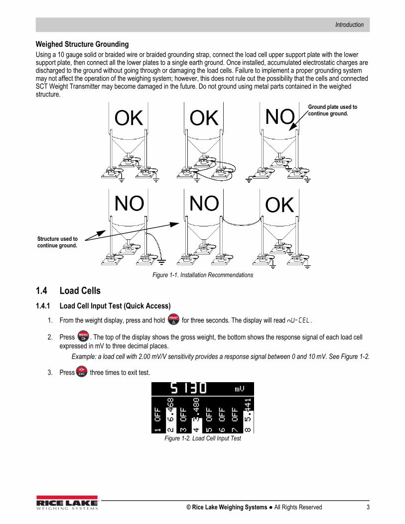
Weighed Structure GroundingUsing a 10 gauge solid or braided wire or braided grounding strap, connect the load cell upper support plate with the lower support plate, then connect all the lower plates to a single earth ground. Once installed, accumulated electrostatic charges are discharged to the ground without going through or damaging the load cells. Failure to implement a proper grounding system may not affect the operation of the weighing system; however, this does not rule out the possibility that the cells and connected SCT Weight Transmitter may become damaged in the future. Do not ground using metal parts contained in the weighed structure.
Figure 1-1. Installation Recommendations
1.4 Load Cells1.4.1 Load Cell Input Test (Quick Access)
1. From the weight display, press and hold for three seconds. The display will read .
2. Press . The top of the display shows the gross weight, the bottom shows the response signal of each load cell expressed in mV to three decimal places.
Example: a load cell with 2.00 mV/V sensitivity provides a response signal between 0 and 10 mV. See Figure 1-2.
3. Press three times to exit test.
Figure 1-2. Load Cell Input Test
Ground plate used to continue ground.
Structure used to continue ground.
MENU
ESC

SCT-40 Series
4 Visit our website www.RiceLake.com
1.4.2 Load Cell TestingLoad Cell Resistance Measurement (Use a Digital Multimeter)
1. Power off the SCT Weight Transmitter.2. The value between the positive signal wire and the negative signal wire must be equal or similar to the one indicated in
the load cell data sheet (output resistance).3. The value between the positive excitation wire and the negative excitation wire must be equal or similar to the one
indicated in the load cell data sheet (input resistance).
Load Cell Voltage Measurement (Use a Digital Multimeter)1. Power on the SCT Weight Transmitter.2. Remove the weight of the scale from the load cell to be tested.3. Make sure that the excitation of the load cell connected to the instrument (or amplifier) is 5 VDC =/- 3 percent.4. Measure the millivolt signal between the positive and negative signal wires by directly connecting them to the multi-
meter, and make sure it reads between 0 and 0.5mV.5. Apply load to the load cell and make sure that there is a signal increment.
If one of the above conditions is not met, please contact Rice Lake Weighing Systems Customer Support for assistance.
1.5 Electrical ConnectionsBasic InformationIt is recommended the negative side of the power supply be grounded.It is possible to supply up to 16 load cells at 350 ohm each.Connect terminal 0 VDC to the RS-485 common when interfacing to A/C powered equipment so that there is an opto-isolated RS-485 connection. In the case of an RS-485 network with several devices, it is recommended to activate the 120 ohm termination resistance on the two devices located at the ends of the network. See Section 2.5.1 on page 20.
IMPORTANT

Introduction
© Rice Lake Weighing Systems ● All Rights Reserved 5
Figure 1-3. Wiring Diagram

SCT-40 Series
6 Visit our website www.RiceLake.com
If all the load cells used are 4-wire, make a jumper between EX-(10) and REF-(7) and between EX+(17) and REF+(20).In the event of difficulty connecting all the reference wires of the installed load cells, connect those of the load cell located at the average distance from the transmitter. The reference wires not used must be individually isolated.
No. Description No. Description1 -Load Cell 1 Signal 22 +Load Cell 7 Signal2 +Load Cell 1 Signal 23 -Load Cell 7 and 8 Excitation (-Ex) Load Cell Shield3 -Load Cell 1 and 2 Excitation (-Ex) Load Cells Shield 24 +Load Cell 7 and 8 Excitation (+Ex)4 +Load Cells 1 and 2 Excitation (+Ex) 25 -Load Cell 8 Signal5 -Load Cell 2 Signal 26 +Load Cell 8 Signal6 +Load Cell 2 Signal 27 Output No. 17 -Load Cell Ref/Sense 28 Output No. 28 -Load Cell 3 Signal 29 Output No. 39 +Load Cell 3 Signal 30 Output No. 4
10 -Load Cells 3 and 4 Excitation (-Ex) Load Cells Shield 31 Output No. 511 +Load Cells 3 and 4 Excitation (+Ex) 32 Output Common12 -Load Cell 4 Signal 33 Input No. 1 (+VDC min 5 V max 24 V)13 +Load Cell 4 Signal 34 Input No. 2 (+VDC min 5 V max 24 V)14 -Load Cell 5 Signal 35 Input No. 3 (+VDC min 5 V max 24 V)15 +Load Cell 5 Signal 36 Input Common (-VDC 0 V)16 -Load Cells 5 and 6 Excitation (-Ex) Load Cells Shield 37 +Analog Output 0÷20 or 4÷20 mA17 +Load Cells 5 and 6 Excitation (+Ex) 38 +Analog Output 0÷10 V18 -Load Cell 6 Signal 39 RS-485: +19 +Load Cell 6 Signal 40 RS-485: -20 +Load Cells Ref/Sense 41 +Supply (12/24 VDC)21 -Load Cell 7 Signal 42 -Supply (12/24 VDC) RS-485: Shield, Gnd,
-Analog Output Common
Table 1-1. Terminals Legend

Introduction
© Rice Lake Weighing Systems ● All Rights Reserved 7
1.6 Key and Symbol Functions
The symbols are activated in sequence within the menus to indicate that a setting and not a weight is being viewed.
Key Short Press in Weigh ModeLong Press (3 s) in Weigh Mode Function within Setup Menus
Semi-automatic zero Zero resetting Press this key to escape from a parameter, cancel or return to previous menu or operation mode.
Captures TareGross Net
Removes TareNet Gross
Press this key to move to the previous parameter or setting in a level, or to scroll to the next digit when setting a parameter value.
Weight print mV load cell test Press this key to move to the next parameter in a level or increment a vaule in when setting a parameter value.
Setting setpoints and hysteresis—
Press this key to move to the next level of configuration or to select and edit a parameter.
Press and hold then press to enter set-up menu for setting general parameters.
Press and hold then press to enter set-up menu for setting preset tare.
Press this key to display the load distribution.
Symbol DescriptionNET This annunciator indicates a net weight when a semi-automatic tare or preset tare has been set.
This annunciator indicates a center of zero with a deviation from zero not more than +/- 0.25 divisions.
This annunciator indicates scale stability.
kg This indicates the unit of measure is kilograms.g This indicates the unit of measure is grams.
W1,W2,W3 Not used
Table 1-2. Key and Symbol Functions
ESC
TARE
MENU
MENUESC
MENUESC
MENU TARE MENU TARE
TEST
0
Note

SCT-40 Series
8 Visit our website www.RiceLake.com
1.7 Instrument Commissioning1. Plug power cord into an outlet to power on the indicator. The display shows in sequence:
• (only in the event of approved program)• Instrument model ()• followed by the software code ()• Program type: bASE (base)• followed by the software version ()• followed by the hardware code ()• Serial number ()
2. Check that the display shows the weight and that there is an increase in weight when loading the load cells.3. If there is not, check and verify the connections and correct positioning of the load cells.4. Confirm the SCT Weight Transmitter has been theoretically calibrated, the load cell’s rated data is already entered,
and that the plant system identification tag is present on the instrument and on the cover.If the SCT Weight Transmitter has not been calibrated, follow the calibration instructions in Section 2.2 before proceeding to next step.
5. Perform a zero setting. See Section 2.2.4 on page 12.6. If the system uses load cells with different sensitivity, perform a theoretical calibration or real calibration.
See Section 2.2.1 on page 9 or Section 2.2.6 on page 13.7. Check the calibration with sample weights and correct the indicated weight if needed. See Section 2.2.6 on page 13.8. Set the desired output type and the full scale value.
• Analog Output Model (Section 2.6 on page 21)• DeviceNet™ Model (Section 3.8 on page 32)• EtherNet/IP™ (Section 3.11 on page 43)• Ethernet TCP/IP (Section 3.12 on page 47)• PROFIBUS-DP® Model (Section 3.9 on page 34)• PROFINET® Model (Section 3.10 on page 38)• Modbus/TCP (Section 3.13 on page 49)
9. If using serial communication, set the related parameter. See Section 2.5 on page 18. 10. If set points are used, set the required weight values and the relevant parameters. See Section 2.12 on page 26 and
Section 2.7 on page 22.
Note

Configuration
© Rice Lake Weighing Systems ● All Rights Reserved 9
2.0 Configuration
2.1 Navigating System MenusUse the following steps when navigating through the system parameter menus.
1. From the weight display, press and hold , then press to access parameter settings.
2. Press to enter a menu or confirm the data entry.
3. Press to modify the displayed figure or menu entry.
4. Press to select a new figure or modify the displayed menu item.
5. Press to cancel and return to the previous menu.For numeric entries, the symbols are activated in sequence within the menus to indicate that a setting and not a weight is being viewed.
1. Press or . The first digit will flash and can be edited.
2. Press to select desired digit.
3. Press to increment digit.
2.2 Calibration2.2.1 Theoretical CalibrationThis function allows the load cell rated values to be set.To perform the theoretical calibration set , , and parameters in sequence.
1. Press and hold , then press . is displayed.
2. Press . is displayed. Press .
3. Press to select desired digit, then press to increment digit until total load cell capacity (system full scale) is displayed.
(Default: ); The system full scale is given by one cell capacity multiplied by the number of cells used. Example: four cells of 1000 kg FULL SCALE = 1000 x 4 = 4000. The instrument is supplied with a theoretical full scale value corresponding to 10000. To restore factory values, set 0 as full scale.
4. Press . is displayed. Press .
5. Press to select desired digit, then press to increment digit until desired load cell mV/V is displayed. (Default: 2.00000 mmV/V): Sensitivity is a load cell rated parameter expressed in mV/V. Set the average sensitivity value indicated on the load cells. It is possible to set a value between 0.50000 and 7.00000 mV/V.
Example: if a four cell system with sensitivity: 2.00100, 2.00150, 2.00200, 2.00250; enter 2.00175, calculated as (2.00100 + 2.0150 + 2.00200 + 2.00250) / 4.
6. Press . is displayed. Press .
7. Press to select desired digit, then press to increment digit until desired display division size is displayed.
MENUESC
MENU
TARE
ESC
PRINT TARE
TARE
MENUESC
MENU MENU
TARE PRINT
MENU MENU
TARE PRINT
MENU MENU
TARE PRINT

SCT-40 Series
10 Visit our website www.RiceLake.com
8. Press . : the division (resolution) is the minimum weight increment value which can be displayed. It is automatically calculated by the system according to the performed calibration, so that it is equal to the 1/10000 of full scale. It can be changed and can vary between 0.0001 and 100 with x1, x2, x5, and x10 increments.
9. This completes the Theoretical Calibration. Press twice to exit setup menu.By modifying the theoretical full scale, the sensitivity or divisions, the Weight (Span) calibration is canceled and only the Theoretical Calibration is considered valid.If the theoretical full scale and the recalculated full scale weight in the Weight (Span) calibration (Section 2.2.6) are equal, the calibration currently in use is Theoretical Calibration; if they are different, the calibration in use is the Weight (Span) Calibration based on test weights.By modifying the theoretical full scale, the sensitivity or divisions and all the system’s parameters containing a weight value will be set to default values.
2.2.2 Maximum CapacityMaximum capacity () is the highest weight of live load/product that can be displayed. When the weight exceeds this value by 9 divisions, the following is displayed: ------. To disable this function, set to 0.
1. Press and hold , then press . is displayed.
2. Press . is displayed.
3. Press or until is displayed. Press .
4. Press to select desired digit, then press to increment digit until desired capacity is displayed.
5. Press
6. Press twice to exit setup menu.
2.2.3 Equalization Use a sample weight equal to at least 50% of the single load cell capacity. At the end of Equalization, perform a Zero Setting (Section 2.2.4).Check the calibration with known weights and correct the indicated weight, if needed, by performing a Weight (Span) Calibration. See Section 2.2.6 on page 13.
Real Equalization
1. Press and hold , then press . is displayed.
2. Press . is displayed.
3. Press or until is displayed.
4. Press . is displayed.
5. Press . is displayed.
6. Unload scale, wait for stability and confirm by pressing . is displayed.
7. Place sample weight on load cell 1 and wait for stability. Confirm by pressing . is displayed.
MENU
ESC
Note
MENUESC
MENU
TARE PRINT MENU
TARE PRINT
MENU
ESC
IMPORTANT
MENUESC
MENU
TARE PRINT
MENU
MENU
MENU
MENU
Configuration
© Rice Lake Weighing Systems ● All Rights Reserved 11
8. Place the sample weight on load cell 2 and wait for stability. Confirm by pressing .
• If equalization is successfully completed, is displayed. Confirm by pressing .
• If an error occurs, is displayed. Confirm by pressing and repeat the equalization procedure.
9. Press three times to exit setup menu.
Theoretical Equalization
1. Press and hold , then press . is displayed.
2. Press . is displayed.
3. Press or until is displayed. Press .
4. Press or until is displayed. Press .
5. Press or to scroll through and set the sensitivity for each load cell (), leaving it at 0 for non-active cells.
6. Press to select desired load cell ().
7. Press to select desired digit, then press to increment digit until desired sensitivity is displayed.
8. Press to accept.
9. Press four times to exit setup menu.
Equalization Coefficients
1. Press and hold , then press . is displayed.
2. Press . is displayed.
3. Press or until is displayed. Press .
4. Press or until is displayed. Press .
5. Press or to scroll through the equalization coefficients () calculated for each active channel.
6. Press four times to exit setup menu.
Equalization Deletion
1. Press and hold , then press . is displayed.
2. Press . is displayed.
3. Press or until is displayed. Press .
4. Press or until is displayed.
MENU
MENU
MENU
ESC
MENUESC
MENU
TARE PRINT MENU
TARE PRINT MENU
TARE PRINT
MENU
TARE PRINT
MENU
ESC
MENUESC
MENU
TARE PRINT MENU
TARE PRINT MENU
TARE PRINT
ESC
MENUESC
MENU
TARE PRINT MENU
TARE PRINT
SCT-40 Series
12 Visit our website www.RiceLake.com
5. Press . is displayed.
6. Press to confirm or press to cancel.
7. Press three times to exit setup menu.
2.2.4 Zero SettingUse Zero Setting to zero the scale after use or to compensate for variations due to environmental factors.Perform this procedure after having set the Theoretical Calibration Data. See Section 2.2.1 on page 9.
This menu may also be accessed directly from the weight display by holding down for three seconds.
1. Press and hold , then press . is displayed.
2. Press . is displayed.
3. Press or until is displayed.
4. Press . The weight value to be set to zero is displayed. In this phase all of the symbols are flashing.
5. Press . The weight is set to zero (the value is stored to the permanent memory).
6. Press to display the value of the total weight reset by the instrument, determined by the sum of all of the previous zero settings.
7. Press three times to exit setup menu.
Diagnostics on Zero
Diagnostics on Zero is performed only if the load distribution has been stored at least once.
If diagnostics on zero has been enabled (Section 2.8.1 on page 24), the display shows the current load distribution and the weight value.
1. Press and hold , then press . is displayed.
2. Press . is displayed.
3. Press or until is displayed.
4. Press . The stored load distribution and weight set to zero are displayed. If the weight is zero and all channels are OFF, it means that no zero setting has been performed.
5. Press . is displayed.
6. Press or to select or .• Select to store the current distribution and the zero mV values. • Select and the current distribution and the zero mV values will not be stored.
7. Confirm by pressing three times. is displayed.
8. Press twice to exit to setup menu.
MENU
MENUESC
ESC
Note ESC
MENUESC
MENU
TARE PRINT
MENU
MENU
ESC
IMPORTANT
MENUESC
MENU
TARE PRINT
MENU
MENU
TARE PRINT
MENU
MENU

Configuration
© Rice Lake Weighing Systems ● All Rights Reserved 13
2.2.5 Zero Value Manual Entry Perform this procedure only if it’s not possible to zero off the scale structure; for example, because it contains product that cannot be unloaded.
1. Press and hold , then press . is displayed.
2. Press . is displayed.
3. Press or until is displayed. Press .
4. Press to select desired digit, then press to increment digit until desired dead load value is displayed (from
0 to 999999, default is 0). Press .
5. Press twice to exit setup menu.
2.2.6 Weight (Span) Calibration (With Test Weights)After performing the Theoretical Calibration (Section 2.2.1), Equalization (Section 2.2.3), and Zero Setting (Section 2.2.4), this function allows correct calibration to be done using test weights of known value. If adjustment is required, change the displayed value to display the test weight value.
1. Load the test weight onto the scale. Use a test weight of at least 50% of the maximum quantity to be weighed.
2. Press and hold , then press . is displayed.
3. Press . is displayed.
4. Press or until is displayed.
5. Press . The value of the weight currently on the system will be flashing on the display. All of the symbols are off. If adjustment is not required, skip to step 8.
6. Adjust the value on the display to match weight loaded on the scale by pressing to select desired digit, then
press to increment digit. The symbols will begin scrolling.
7. Press . The new set weight will appear on the display with all the symbols flashing.
8. Press . is displayed.
9. Press twice to exit setup menu.Example: For a system with maximum capacity of 1000 kg and 1 kg division, two test weights are available: one 500 kg and one 300 kg. Load both weights onto the system and correct the indicated weight to 800 kg. Remove 300 kg weight, the system will show 500 kg. Remove the 500 kg weight and the system will read zero. If this does not happen, it means there is a mechanical problem affecting the system linearity.
Identify and correct any mechanical problems before repeating the procedure.
If the theoretical full scale and recalculated full scale in the Weight (Span) Calibration are equal, it means that the Theoretical Calibration is currently in use; otherwise, the Weight (Span) Calibration based on test weights is in use.If the correction made changes the previous full scale for more than 20 percent, all the parameters with settable weight values are reset to default values.
IMPORTANT
MENUESC
MENU
TARE PRINT MENU
TARE PRINT
MENU
ESC
MENUESC
MENU
TARE PRINT
MENU
TARE
MENU
MENU
ESC
IMPORTANT
Note
SCT-40 Series
14 Visit our website www.RiceLake.com
Linearization Option on Max 5 PointsIt is possible to perform a linearization of the weight by performing the Weight (Span) Calibration (With Test Weights) (see Section 2.2.6 on page 13) with up to a maximum of five points, using five different test weights. The procedure ends by pressing
or after entering the fifth value. At this point it will no longer be possible to change the calibration value; a new Weight (Span) Calibration would need to be performed. To perform a new calibration, return to the weight display and then re-enter the calibration menu.
By pressing after the sample weight is confirmed, the full scale displays the value of the maximum test weight entered and references the cell sensitivity set in the Theoretical Calibration (Section 2.2.1 on page 9).
2.2.7 Confirmation and Change of Active ChannelsAfter performing the calibration and verifying the system works properly, this function allows the channels to be automatically detected by the instrument. This ensures that in the event of accidental interruption of the cable of one or more load cells, the instrument displays thealarm.Automatic load cell detection is enabled by default on all eight channels of the instrument.
1. Press and hold , then press . is displayed.
2. Press . is displayed.
3. Press or until is displayed.
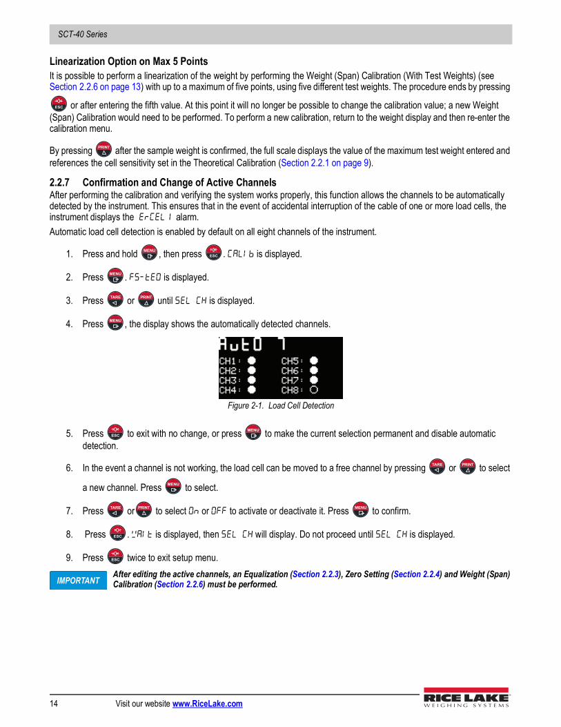
4. Press , the display shows the automatically detected channels.
Figure 2-1. Load Cell Detection
5. Press to exit with no change, or press to make the current selection permanent and disable automatic detection.
6. In the event a channel is not working, the load cell can be moved to a free channel by pressing or to select
a new channel. Press to select.
7. Press or to select or to activate or deactivate it. Press to confirm.
8. Press . is displayed, then will display. Do not proceed until is displayed.
9. Press twice to exit setup menu.After editing the active channels, an Equalization (Section 2.2.3), Zero Setting (Section 2.2.4) and Weight (Span) Calibration (Section 2.2.6) must be performed.
ESC
MENUESC
MENU
TARE PRINT
MENU
ESCMENU
TARE PRINT
MENU
TARE PRINT MENU
ESC
ESC
IMPORTANT
Configuration
© Rice Lake Weighing Systems ● All Rights Reserved 15
To Cancel Manual Selection of Active Channels:When the manual selection of the active channels is canceled, automatic detection on all channels is then enabled.
1. Press and hold , then press . is displayed.
2. Press . is displayed.
3. Press or until is displayed.
4. Press . is displayed.
5. Press to cancel or press to confirm. will display. Do not proceed until displays.
6. Press twice to exit setup menu.
2.2.8 Setting Units of MeasureUse the following steps to set the Units of Measure on the SCT Weight Transmitter. If the print function is enabled, the symbol of the selected unit of measure will be printed after the measured value.
1. Press and hold , then press . is displayed.
2. Press . is displayed.
3. Press or until is displayed. Press .
4. Press or until desired unit is displayed. Press .
5. Press twice to exit setup menu.
Unit Display Description Kilograms Grams Tons Pounds* Newtons* Liters* Bars* Atmospheres* Pieces* Newton meters* Kilogram meters* Other generic units of measure not included on the list** Indicates it is possible to set the display coefficient. To use it is necessary to enable it, closing the COEFF input. See Section 2.2.9 on page 16.
Table 2-1. Units of Measure
MENUESC
MENU
TARE PRINT
MENU
ESCMENU
ESC
MENUESC
MENU
TARE PRINT MENU
TARE PRINT MENU
ESC

SCT-40 Series
16 Visit our website www.RiceLake.com
2.2.9 Display CoefficientBy setting the coefficient (), the display is changed accordingly. If one of the inputs is set to mode (Section 2.7 on page 22), when the input is closed the value displayed will be modified according to the coefficient. When the input is opened, the standard weight display will be restored.
1. Press and hold , then press . is displayed.
2. Press . is displayed.
3. Press or until is displayed.Press .
4. Press to select desired digit, then press to increment digit until desired number is displayed.
5. Press to accept.
6. Press twice to exit setup menu.
All other settings (setpoints, hysteresis, calibration) are expressed in weight value. To convert them to the new unit of measurement, perform a Theoretical Calibration For Other Units Of Measure or a Weight (Span) Calibration For Other Units Of Measure to change the system calibration.The parameter must remain set to 1.0000.
Theoretical Calibration For Other Units Of MeasureSet in the parameter the F.SCALE value divided by the conversion coefficient from kg to the new unit of measure.Example: The four load cells of 1000 kg are placed under a scale for olive oil, which has a specific gravity of 0.916 kg/L. Setting the F.SCALE = (4x1000)/0.916 = 4367, the system works in liters of olive oil. See Section 2.2.8 on page 15.
Weight (Span) Calibration For Other Units Of MeasureLoad a known quantity of product liters on the scale, use as high a percentage of the maximum quantity to be weighed as possible, and enter in the parameter , the product loaded value in liters. See Section 2.2.8 on page 15.
Display Definition Display CoefficientLb Pounds The value set in will be multiplied by the weight value currently displayed.nEWton Newton The value set in will be multiplied by the weight value currently displayed.LItrE Liters In set the specific weight in KG/l, assuming that the system is calibrated in kg.bAr Bar The value set in will be multiplied by the weight value currently displayed.AtM Atmosphere The value set in will be multiplied by the weight value currently displayed.PIECE Pieces In set the weight of one piece.new-M Newton meters The value set in will be multiplied by the weight value currently displayed.KILO-M Kilogram meters The value set in will be multiplied by the weight value currently displayed.Other Other generic units of measure not
included on the listThe value set in will be multiplied by the weight value currently displayed.
Table 2-2. Display Coefficient
MENUESC
MENU
TARE PRINT MENU
TARE PRINT
MENU
ESC
IMPORTANT

Configuration
© Rice Lake Weighing Systems ● All Rights Reserved 17
2.3 Filter on the WeightThe filtering selection is used to eliminate environment noise, and is typically a compromise between responsiveness and stability. The lower the number, the more responsive the display will be to weight changes. The filter is used to stabilize a weight as long as the variations are smaller than the corresponding Response Time (Table 2-3 on page 17). The filter setting is dependent on the type of application and the required update rate.Setting the parameter allows a stable weight display to be obtained. To increase the effect (weight more stable) increase the value.
1. Press and hold , then press . is displayed.
2. Press or until is displayed.
3. Press . The currently programmed filter value is displayed.
4. Press or until desired filter value is displayed.
5. Press to accept. is displayed. The current weight then displays, with all symbols scrolling, and the displayed stability can be experimentally verified.
• If stability is not satisfactory, press twice. This returns the indicator to the option and the filter may be modified again until an optimum result is achieved.
• If stability is satisfactory, press , is displayed. Do not proceed until is displayed. Then press once to set anti-peak filter.
The anti-peak filter can only be set if the instrument is connected to one load cell.When the weight is stable, the anti-peak filter removes any sudden disturbances with a maximum duration of one second.
6. Press or to display or .
7. Press to accept. will display.
8. Press to exit setup menu.
Filter Value Response Time(ms)
Display and Serial Port Refresh Frequency
(Hz)0 12 3001 150 1002 260 503 425 254 850 12.55 1700 12.56 2500 12.57 4000 108 6000 109 7000 5
Anti-peak 6 600
Table 2-3. Filter Values
MENUESC
TARE PRINT
MENU
TARE PRINT
MENU
ESC
MENUESC
Note
TARE PRINT
MENU
ESC

SCT-40 Series
18 Visit our website www.RiceLake.com
2.4 Zero Parameters1. Press and hold , then press . is displayed.
2. Press or until is displayed. Press .
3. Press or until desired parameter is displayed. Press .
4. Press to select desired digit, then press to increment digit until desired value is displayed.
5. Press .
6. Press twice to exit setup menu.
2.5 Serial Communication Setting1. Press and hold , then press . is displayed.
2. Press or until is displayed.
3. Press . is displayed. Press .
4. Press until desired parameter is displayed. See Table 2-5 on page 19.
5. Press to select.
6. Press or until desired setting is displayed, or if necessary, press to select desired digit, then press
to increment digit until desired value is displayed. See Table 2-6 on page 19.
7. Press to select.
8. Press three times to exit setup menu.
Parameter Options Description Enter number
0-max full scale???Considered decimals:300 – 30.0 – 3.00 – 0.300
Maximum zero rangeIndicates the maximum weight value that can be zeroed off by external contact, keypad or serial protocol.
Enter number0 - max 20% of full scale?
Automatically zeroes the scale at power-on.If the weight value is lower than the value set in this parameter, the scale will zero itself provided the weight does not exceed the value in the 0 SET parameter. Todisable this function set to 0.
n0nE1-5
Zero trackingAutomatically zeros the scale when within the range specified, as long as the weight is within the 0 SET parameter and the scale is at standstill for at least one second. To disable this function, set to none.Example: if the parameter dI UI S is set to 5 and is set to 2, the weight will be automat-ically set to zero for variations smaller than or equal to 10 ( x
Table 2-4. Zero Parameters
MENUESC
TARE PRINT MENU
TARE PRINT MENU
TARE PRINT
MENU
ESC
MENUESC
TARE PRINT
MENU MENU
TARE
MENU
TARE PRINT TARE
MENU
ESC
Configuration
© Rice Lake Weighing Systems ● All Rights Reserved 19
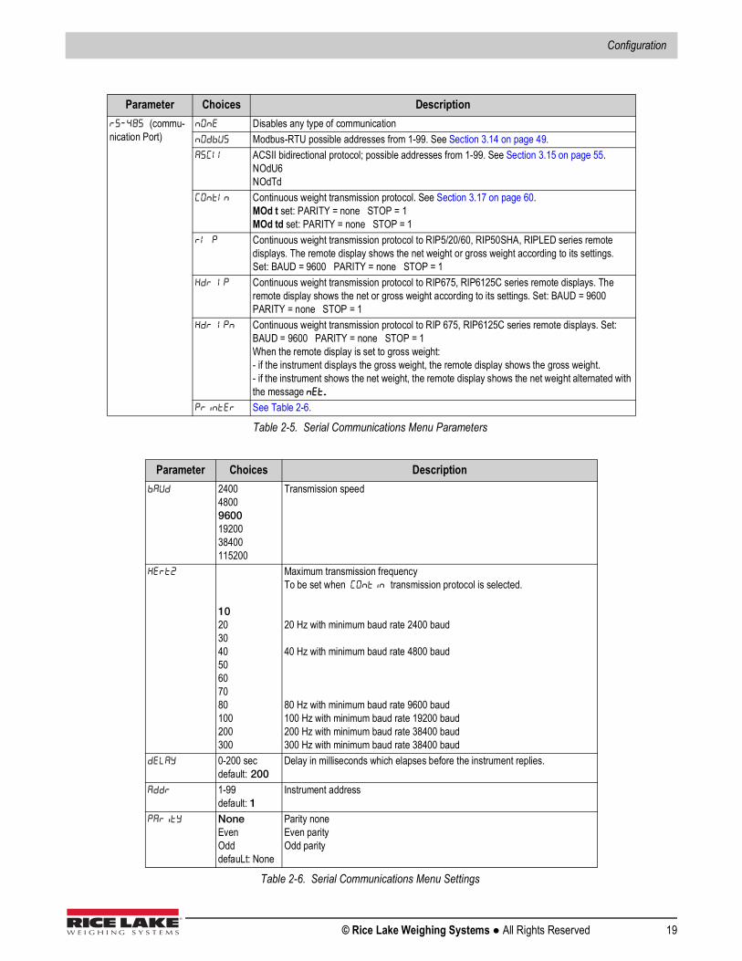
Parameter Choices Description(commu-nication Port)
Disables any type of communication Modbus-RTU possible addresses from 1-99. See Section 3.14 on page 49. ACSII bidirectional protocol; possible addresses from 1-99. See Section 3.15 on page 55.
NOdU6NOdTd
Continuous weight transmission protocol. See Section 3.17 on page 60.MOd t set: PARITY = none STOP = 1MOd td set: PARITY = none STOP = 1
Continuous weight transmission protocol to RIP5/20/60, RIP50SHA, RIPLED series remote displays. The remote display shows the net weight or gross weight according to its settings.Set: BAUD = 9600 PARITY = none STOP = 1
Continuous weight transmission protocol to RIP675, RIP6125C series remote displays. The remote display shows the net or gross weight according to its settings. Set: BAUD = 9600 PARITY = none STOP = 1
Continuous weight transmission protocol to RIP 675, RIP6125C series remote displays. Set: BAUD = 9600 PARITY = none STOP = 1When the remote display is set to gross weight:- if the instrument displays the gross weight, the remote display shows the gross weight.- if the instrument shows the net weight, the remote display shows the net weight alternated with the message
See Table 2-6.
Table 2-5. Serial Communications Menu Parameters
Parameter Choices Description 2400
480096001920038400115200
Transmission speed
1020304050607080100200300
Maximum transmission frequencyTo be set when transmission protocol is selected.
20 Hz with minimum baud rate 2400 baud
40 Hz with minimum baud rate 4800 baud
80 Hz with minimum baud rate 9600 baud100 Hz with minimum baud rate 19200 baud200 Hz with minimum baud rate 38400 baud300 Hz with minimum baud rate 38400 baud
0-200 secdefault: 200
Delay in milliseconds which elapses before the instrument replies.
1-99default: 1
Instrument address
NoneEvenOdddefauLt: None
Parity noneEven parityOdd parity
Table 2-6. Serial Communications Menu Settings

SCT-40 Series
20 Visit our website www.RiceLake.com
For information about protocols and methods of communication Contact Rice Lake Weighing Systems Customer Support.
2.5.1 RS-485 Serial Communication
Figure 2-2. RS-485 Serial Communication
If the RS-485 network exceeds 100 meters in length or a baud rate over 9600 is used, two terminating resistors are needed at the ends of the network. Two 120 ohm resistors must be connected between the + and - terminals of the line, on the terminal strip of the furthest instruments.
1-2default: 1
Stop bit
1-9default: 1
Number of copies
Number of blank lines between one printout and the next. yes or no
default: noPrinting custom heading from PC
P 190StAUPStAUt
Connected printer type
Parameter Choices Description
Table 2-6. Serial Communications Menu Settings (Continued)
Note
Note
Configuration
© Rice Lake Weighing Systems ● All Rights Reserved 21
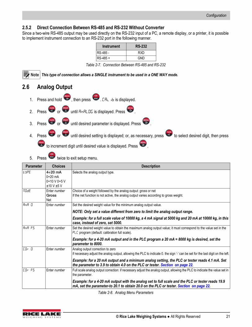
2.5.2 Direct Connection Between RS-485 and RS-232 Without ConverterSince a two-wire RS-485 output may be used directly on the RS-232 input of a PC, a remote display, or a printer, it is possible to implement instrument connection to an RS-232 port in the following manner.
This type of connection allows a SINGLE instrument to be used in a ONE WAY mode.
2.6 Analog Output
1. Press and hold , then press . is displayed.
2. Press or until is displayed. Press .
3. Press or until desired parameter is displayed. Press .
4. Press or until desired setting is displayed; or, as necessary, press to select desired digit, then press
to increment digit until desired value is displayed. Press .
5. Press twice to exit setup menu.
Instrument RS-232RS-485 - RXDRS-485 + GND
Table 2-7. Connection Between RS-485 and RS-232
Parameter Choices Description 4÷20 mA
0÷20 mA0÷10 V 0÷5 V ±10 V ±5 V
Selects the analog output type.
Enter numberGrossNet
Choice of a weight followed by the analog output: gross or netIf the net function is not active, the analog output varies according to gross weight.
Enter number Set the desired weight value for the minimum analog output value.
NOTE: Only set a value different from zero to limit the analog output range.Example: for a full scale value of 10000 kg, a 4 mA signal at 5000 kg and 20 mA at 10000 kg, in this case, instead of zero, set 5000.
Enter number Set the desired weight value to obtain the maximum analog output value; it must correspond to the value set in the program (default: calibration full scale).
Example: for a 4-20 mA output and in the PLC program a 20 mA = 8000 kg is desired, set the parameter to 8000.
Enter number Analog output correction to zeroif necessary adjust the analog output, allowing the PLC to indicate 0. the sign ‘-’ can be set for the last digit on the left.
Example: for a 20 mA output and a minimum analog setting, the PLC or tester reads 4.1 mA. Set the parameter to 3.9 to obtain 4.0 on the PLC or tester. Section on page 22.
Enter number Full scale analog output correction: if necessary adjust the analog output, allowing the PLC to indicate the value set in the parameter.
Example: for a 4-20 mA output with the analog set to full scale and the PLC or tester reads 19.9 mA, set the parameter-to 20.1 to obtain 20.0 on the PLC or tester. Section on page 22.
Table 2-8. Analog Menu Parameters
Note
MENUESC
TARE PRINT MENU
TARE PRINT MENU
TARE PRINT TARE
PRINT MENU
ESC

SCT-40 Series
22 Visit our website www.RiceLake.com
Analog Output Type Scale CorrectionsThe minimum and maximum values which can be set for the zero and full scale corrections. Refer to and .
The analog output may also be used in the opposite manner, where. the weight setting that corresponds to the analog zero () may be greater than the weight set for the analog full scale (). The analog output will increase towards full scale as the weight decreases; the analog output will decrease as the weight increases.Example: analog output type having selected 0-10 V: = 10000 = 0Weight = 0 kg analog output = 10 VWeight= 5000 kg analog output = 5 VWeight = 10000 kg analog output = 0 V
2.7 Outputs And Inputs Configuration1. Press and hold , then press . is displayed.
2. Press or until is displayed. Press .
3. Press or until desired parameter is displayed. Press .
4. Press or until desired setting is displayed.
5. Press . Press twice to exit setup menu.
Analog Output Type Minimum Maximum0-10 V -0.150 10.2000-5 V -0.150 5.5000-20 mA -0.200 22.0004-20 mA -0.200 22.000
Table 2-9. Analog Output Scale Corrections
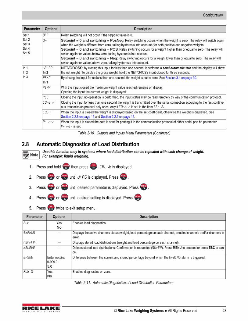
Parameter Options DescriptionOUt 1OUt 2OUt 3OUt 4Out 5
OpenClose
Normally open: The relay is de-energized and the contact is open when the weight is lower than the programmed setpoint value. It closes when the weight is higher than or equal to the programmed setpoint value.Normally closed: The relay is energized and the contact is closed when the weight is lower than the programmed set-point value. It opens when the weight is higher than or equal to the programmed setpoint.
OUt 1OUt 2OUt 3OUt 4Out 5
Set 1Set 2Set 3Set 4Set 5
Number corresponds with Out 1, 2, 3, 4, or 5The contact will switch on the basis of weight according to setpoints. See Section 2.12 on page 26.For each setpoint select:Gross (default) - The contact will switch on the basis of gross weight.Net - The contact will switch on the basis of net weight.
PLC The contact will not switch on the basis of weight, but is controlled by remote protocol commands.Stable Relay switching occurs when the weight is stableAlarm Relay switching occurs when one of the following alarms is triggered: ,,,,,
, The operation mode is forced to close (normally closed).
Set 1Set 2Set 3Set 4Set 5
The contact will switch on the basis of gross weight. The contact will switch on the basis of net weight. Relay switching occurs for both positive and negative weight values. Relay switching occurs for positive weight values only. Relay switching occurs for negative weight values only.
Table 2-10. Outputs and Inputs Menu Parameters
Note
MENUESC
TARE PRINT MENU
TARE PRINT MENU
TARE PRINT
MENUESC
Configuration
© Rice Lake Weighing Systems ● All Rights Reserved 23
2.8 Automatic Diagnostics of Load DistributionUse this function only in systems where load distribution can be repeated with each change of weight. For example: liquid weighing.
1. Press and hold then press . is displayed.
2. Press or until is displayed. Press .
3. Press or until desired parameter is displayed. Press .
4. Press or until desired setting is displayed. Press .
5. Press twice to exit setup menu.
Set 1Set 2Set 3Set 4Set 5
Relay switching will not occur if the setpoint value is 0. Setpoint = 0 and switching = PosNeg: Relay switching occurs when the weight is zero. The relay will switch again
when the weight is different from zero, taking hysteresis into account (for both positive and negative weights.Setpoint = 0 and switching = POS: Relay switching occurs for a weight higher than or equal to zero. The relay will switch again for values below zero, taking hysteresis into account.Setpoint = 0 and switching = Neg: Relay switching occurs for a weight lower than or equal to zero. The relay will switch again for values above zero, taking hysteresis into account.
In 1In 2In 3
In 2 NET/GROSS: by closing this input for less than one second, it performs a semi-automatic tare and the display will show the net weight. To display the gross weight, hold the NET/GROSS input closed for three seconds.
In 1
By closing the input for no less than one second, the weight is set to zero. See Section 3.4 on page 30.
With the input closed the maximum weight value reached remains on display. Opening the input the current weight is displayed.
Closing the input no operation is performed, the input status may be read remotely by way of the communication protocol. Closing the input for less than one second the weight is transmitted over the serial connection according to the fast continu-
ous transmission protocol only once. only if is set in the item . When the input is closed the weight is displayed based on the set coefficient, otherwise the weight is displayed. See
Section 2.2.8 on page 15 and Section 2.2.9 on page 16. When the input is closed the data is sent for printing if in the communication protocol of either serial port he parameter
is set.
Parameter Options Description Yes
NoEnables load diagnostics.
— Displays the active channels status (weight, load percentage on each channel, enabled channels and/or channels in error.
— Displays stored load distributions (weight and load percentage on each channel). — Deletes stored load distributions: Confirmation is requested (). Press MENU to proceed or press ESC to can-
cel. Enter number
0-999.95.0
Difference between the current and stored percentage beyond which the alarm is triggered.
YesNo
Enables diagnostics on zero.
Table 2-11. Automatic Diagnostics of Load Distribution Parameters
Parameter Options Description
Table 2-10. Outputs and Inputs Menu Parameters (Continued)
Note
MENUESC
TARE PRINT MENU
TARE PRINT MENU
TARE PRINT MENU
ESC

SCT-40 Series
24 Visit our website www.RiceLake.com
2.8.1 Load DiagnosticsThe instrument, with stable weight, calculates and stores the load percentage on each channel. If under normal operation, the load percentage error is higher than the value set in parameter , the display shows the alarm alternated with
the weight. The alarm also remains active upon instrument power-off. Press to cancel.
2.8.2 Diagnostics on ZeroWhen a zero setting is performed from the menu, the instrument calculates the load percentage on each channel. Diagnostics on zero is performed only if the load distribution has been stored at least once.See Section 2.2.4 on page 12. When using an unloaded system, where the load percentage is higher than the value set in parameter , the display shows the alarm alternated with the weight. The alarm also remains active upon instrument power-off.
Press to cancel.Example: current load distribution display:
Figure 2-3. Current Load Distribution Display
The top of the display shows the weight on the scale; the bottom shows the load percentage on each active channel. This
screen can also be accessed directly from the weight display by pressing .
2.9 Test1. Press and hold then press . is displayed.
2. Press or until is displayed. Press .
3. Press or until desired parameter is displayed. See Table 2-12. Press .
4. Press or until desired setting is displayed. See Table 2-12. Press .
5. Press twice to exit setup menu.
Enter number0-999.95.0
Difference between the current and stored percentage beyond which the alarm is triggered.
— Displays current load distribution on zero and the one previously stored (weight, load percentage on each channel).
Parameter Options Description — Load Distribution: Displays the active channels status (weight load percentage on each channel, enabled channels
and/or channels in error. This menu can also be accessed directly from the weight display by pressing TEST. — Input Test: Zero is displayed for each open input. One is displayed when the input is closed.
Output Test: Setting zero ensures that the corresponding output opens. Setting one ensures that the corresponding output closes.
Table 2-12. Test Parameters
Parameter Options Description
Table 2-11. Automatic Diagnostics of Load Distribution Parameters (Continued)
MENU
MENU
TEST
MENUESC
TARE PRINT MENU
TARE PRINT MENU
TARE PRINT MENU
ESC

Configuration
© Rice Lake Weighing Systems ● All Rights Reserved 25
2.10 Events Log1. Press and hold then press . is displayed.
2. Press or until is displayed. Press .
3. Press or until desired parameter is displayed. Press .
4. Press or to scroll through events.
5. Press on an event to display.
6. Press to return to events listing.
7. Press three times to exit menu.
Allows the analog signal to range between the minimum and maximum values starting from the minimum. Current output test Voltage output test
— Millivolt test: Displays the response signal of each load cell expressed in mV with three decimals. — Millivolt stored at zero setting (only if = ): displays the response signal of each load cell expressed in mV
with three decimals.
Parameter Options Description Zero setting from the calibration menu: Press MENU to display the value set to zero.
Theoretical calibration: Press MENU to display the full scale set. Real calibration: Press MENU to display the sample weight used. Tare setting via the keypad: Press MENU to display the set value. Load distribution error: Press MENU to display the weight value that triggered the alarm. Press MENU again to dis-
play the difference between he load percentage and the stored value. Weight alarm: Press MENU to display the alarm type. Load distribution deletion Equalization Modification or deletion of the manual selection of active channels
— Delete stored events: Confirmation is requested (), press MENU to proceed or press ESC to cancel. — Prints all events.
Table 2-13. Events Log Parameters
Parameter Options Description
Table 2-12. Test Parameters (Continued)
MENUESC
TARE PRINT MENU
TARE PRINT MENU
TARE PRINT
MENU
MENU
ESC
SCT-40 Series
26 Visit our website www.RiceLake.com
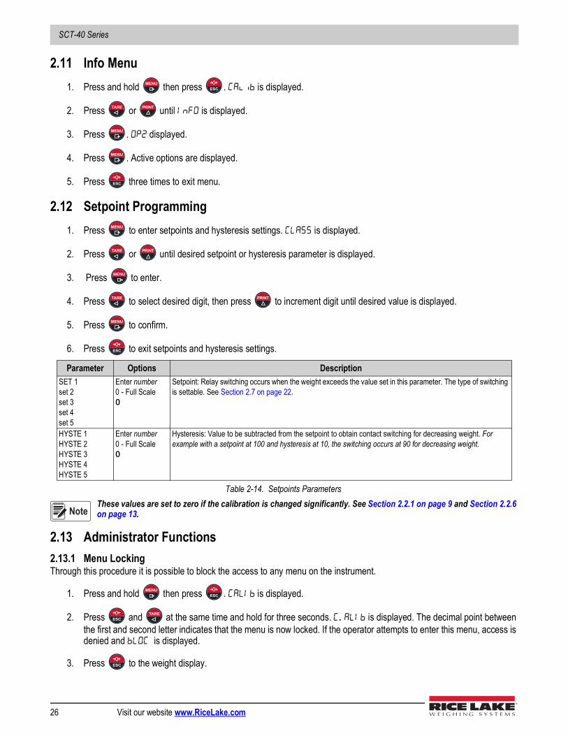
2.11 Info Menu1. Press and hold then press . is displayed.
2. Press or until is displayed.
3. Press . displayed.
4. Press . Active options are displayed.
5. Press three times to exit menu.
2.12 Setpoint Programming1. Press to enter setpoints and hysteresis settings. is displayed.
2. Press or until desired setpoint or hysteresis parameter is displayed.
3. Press to enter.
4. Press to select desired digit, then press to increment digit until desired value is displayed.
5. Press to confirm.
6. Press to exit setpoints and hysteresis settings.
These values are set to zero if the calibration is changed significantly. See Section 2.2.1 on page 9 and Section 2.2.6 on page 13.
2.13 Administrator Functions2.13.1 Menu LockingThrough this procedure it is possible to block the access to any menu on the instrument.
1. Press and hold then press . is displayed.
2. Press and at the same time and hold for three seconds. is displayed. The decimal point between the first and second letter indicates that the menu is now locked. If the operator attempts to enter this menu, access is denied and is displayed.
3. Press to the weight display.
Parameter Options DescriptionSET 1set 2set 3set 4set 5
Enter number0 - Full Scale0
Setpoint: Relay switching occurs when the weight exceeds the value set in this parameter. The type of switching is settable. See Section 2.7 on page 22.
HYSTE 1HYSTE 2HYSTE 3HYSTE 4HYSTE 5
Enter number0 - Full Scale0
Hysteresis: Value to be subtracted from the setpoint to obtain contact switching for decreasing weight. For example with a setpoint at 100 and hysteresis at 10, the switching occurs at 90 for decreasing weight.
Table 2-14. Setpoints Parameters
MENUESC
TARE PRINT
MENU
MENU
ESC
MENU
TARE PRINT
MENU
TARE PRINT
MENU
ESC
Note
MENUESC
ESCTARE
ESC

Configuration
© Rice Lake Weighing Systems ● All Rights Reserved 27
2.13.2 Menu Unlocking
1. Press and hold then press . is displayed.
2. Press and at the same time and hold for three seconds. is displayed. The decimal point between the first and second letter is gone, indicating the menu is now unlocked.
3. Press to exit to the weight display.
2.13.3 Temporary Menu Locking
1. Press and hold then press . is displayed.
2. Press and at the same time and hold for three seconds. is displayed. The decimal point between the first and second letter is gone, indicating the menu is now unlocked and it is possible to enter and modify all menus.
3. Press to exit to the weight display. By returning to the weight display, the menu lock is restored.
2.13.4 Data Deletion
Contact technical support prior to performing data deletion.
After each operation the display shows , press MENU to continue. By pressing ESC the procedure is canceled and no changes are made.
1. With power off, press and hold , then power on. is displayed and constants restore (Calibration is not
erased). Press .
2. Press or until is displayed. Press .
3. Press to select desired digit, then press to increment digit and enter code 6935.
4. Press to confirm. is displayed.5. Instrument will reboot.
2.13.5 Program SelectionScale approval state is preset for not-legal. For other choices please contact technical support.
1. With power off, press and hold , then power on. is displayed and constants restore (does not erase
calibration. Press .
2. Press or to program.
3. Press is displayed and the instrument is restored to default and data is erased. Or, press to quit the program without introducing any changes and without deleting any of the set variables.
If necessary, a manual for the newly set program can be requested from technical support.
Parameter Choices Description Not Legal for Trade Scale capacity is displayed when the scale is empty; as weight is added, the display will count down Continuous weight transmission protocol, streams net and gross. (Set BAUD= 9600, Parity=none, Stop=1)
Table 2-15. Program Selection
MENUESC
MENU PRINT
ESC
MENUESC
TARE PRINT
ESC
IMPORTANT
Note
ESC
MENU
TARE PRINT MENU
TARE PRINT
MENU
ESC
MENU
TARE PRINT
MENUESC
IMPORTANT

SCT-40 Series
28 Visit our website www.RiceLake.com
2.13.6 Keypad or Display Locking
1. Press immediately followed by . Hold both down for about 5 seconds. This operation is also possible via the Modbus and ASCII protocols.
2. Press or until desired parameter is displayed. Press .
Parameter Description No lock Keypad Lock: If active, when a key is pressed the message is displayed. Keypad and Display Lock: If active, the keypad is locked and the display shows the instrument model (weight is not displayed); by
pressing a key the display shows for three seconds.
Table 2-16. Keypad or Display Locking Parameters
ESCPRINT
TARE PRINT MENU

Operation
© Rice Lake Weighing Systems ● All Rights Reserved 29
3.0 Operation
3.1 Navigating System MenusUse the following steps when navigating through the system parameter menus.
1. From the weight display, press and hold , then press to access parameter settings.
2. Press to enter a menu or confirm the data entry.
3. Press to modify the displayed figure or menu entry.
4. Press to select a new figure or modify the displayed menu item.
5. Press to cancel and return to the previous menu.For numeric entries, the symbols are activated in sequence within the menus to indicate that a setting and not a weight is being viewed.
1. Press or . The first digit will flash and can be edited.
2. Press to select desired digit.
3. Press to increment digit.
3.2 Semi-automatic Tare (Net/Gross)The semi-automatic tare value is lost upon instrument power-off.The semi-automatic tare operation is not available if the gross weight is zero.
1. To perform a net operation (Semi-Automatic Tare), close the Net/Gross input or press TARE for less than three seconds. The instrument displays the net weight (just set to zero) and the Net LED lights up.
2. To display the gross weight again, keep the Net/Gross input closed or press TARE for three seconds.3. This operation can be repeated by the operator to allow the loading of several products.
Press and hold PRINT to display the gross weight temporarily. When PRINT is released, the net weight will be displayed again. The semi-automatic tare operation is not available if the gross weight is zero.
3.3 Preset Tare (Subtractive Tare Device)It is possible to manually set a preset tare value to be subtracted from the display value provided that the is less than Max capacity.
1. Press and at the same time and hold for three seconds. is displayed.
2. Press . By default the instrument displays the last programmed preset tare.
3. Press then press to apply or, press to select desired digit, then press to increment digit until
desired value is displayed. Press to apply.
4. Press to exit .
Press and hold PRINT to display gross weight. When PRINT is released, the net weight will be displayed again.
MENUESC
MENU
TARE
ESC
PRINT TARE
TARE
Note
Note
MENU TARE
MENU
PRINT MENU TARE PRINT
MENU
ESC
Note

SCT-40 Series
30 Visit our website www.RiceLake.com
To delete a preset tare and return to gross weight display:
1. Press and hold for three seconds or keep the Net/Gross input, if any, closed for three seconds. The reset tare value is set to zero. The NET symbol is turned off when the gross weight is displayed again.
If a Semi-automatic Tare (Net/Gross) is entered, it is not possible to access the Preset Tare (Subtractive Tare Device) function.If a Preset Tare (Subtractive Tare Device) is entered, it is still possible to access the Semi-automatic Tare Net/Gross function. The two different types of tare are added.The Semi-automatic Tare (Net/Gross) and Preset Tare (Subtractive Tare Device) functions will be lost when the instrument is turned off.
3.4 Semi-automatic Zero (Weight Zero Setting for Small Variations)Closing the Semi-Automatic Zero input will set the weight to zero. Alternatively the weight is set to zero by:
1. Press for less than three seconds. is displayed for three seconds.
2. Press to set weight to zero.This function is only allowed if the weight is lower than the Zero Setting value (Section 2.2.4), otherwise the alarm appears and the weight is not set to zero.The Zero Setting will be lost when the instrument is turned off.
3.5 PeakKeeping the Peak input closed displays the maximum weight value reached. Opening the input displays the current weight.
To use this input to view a sudden variation peak, set the FILTER ONT THE WEIGHT to zero.
3.6 AlarmsDisplay Description
No load cell detected; check the connections. The load cell signal exceeds 39 mV; the conversion electronics (AD converter) is malfunctioning. The references are not connected or are incorrectly connected; the load cell is a 4 and there are no jumpers between EX- and REF- and
between EX+ and REF+. The load cell is not connected or is incorrectly connected. The number indicates the channel on which the error is detected. The weight display exceeds 110% of the full scale. Internal instrument converter failure; check load cell connections. If necessary contact technical support. The weight exceeds the maximum capacity by 9 divisions. The maximum displayable value is exceeded (value higher than 999999 or lower than -999999). The weight is too high and zero setting is not possible. This message appears in sample weight setting, in real calibration, after the fifth sample weight value has been entered. The value set for the parameter is beyond the permitted values. Press ESC to quit the setting mode leaving the previous value unchanged.
Examples: a number of decimals is selected for full scale which exceed the instrument’s display potential; value above the maximum set-ting value; the weight value set in sample weight verification does not match the detected mV increase; the analog output correction goes beyond the permitted limits.
Lock is active on a menu item, the keypad or the display. Unable to display the number properly because it is greater than 999999 or less than -999999. The current load has been equalized; press MENU to go back to the previous step and move the sample weight onto the next load cell. The sample weight was not loaded or is too light. The load percentage error is higher than the value set in parameter or . Press MENU to cancel the alarm. The gross weight is equal to zero and the semi-automatic tare operation cannot be performed.
Table 3-1. Alarms
TARE
Note
ESC
MENU
Note
Note

Operation
© Rice Lake Weighing Systems ● All Rights Reserved 31
Serial Protocol Alarms
For RIP remote displays, if the message exceeds five digits ------ displays.
If an alarm becomes active, the relays open and the analog outputs go to the lowest possible value.
3.7 Printing ExamplesBasic PrintoutIf the printer has been set (Section 2.5 on page 18) from the weight display, press .
Figure 3-1. Printout Examples
Load Distribution PrintoutTo print the current distribution:
1. Press . The current load distribution is displayed.
2. Press .
Figure 3-2. Current Distribution Printout
MODE
Bit LSB 76543210xxxxxxx1
7654321xxxx1xxx
7654321xxxxxx1x
7654321xxxxx1xx
76534321on gross:xxx1xxxxOn net:xx1xxxxx
The response to the zero command is a “value not valid” error.(error code 3)
Status RegisterModbus RTU
ASCII
RIP
HDRIP-N ######
CONTIN
Table 3-2. Serial Protocol Alarms
RANGE 0-20 mA 4-20 ma 0-5 V 0-10 V
Output Value -0.2 mA 3.5 mA -0.5 V -0.5 V
Table 3-3. Analog Outputs with Active Alarms
Note
TEST
Load cell connected but has an errorLoad cell not connected

SCT-40 Series
32 Visit our website www.RiceLake.com
To print current and stored distribution:
1. Press and hold , then press . is displayed.
2. Press or until is displayed.
3. Press . is displayed.
4. Press or until is displayed.
5. Press . The load and weight distribution is displayed.
6. Press and hold for more than 3 seconds.
7. Press three times to return to the weigh mode.
Figure 3-3. Current and Stored Distribution Printout
3.8 SCT-40 DeviceNetThe SCT-40 DeviceNet works as a source in a DeviceNet network.Load the included EDS file (DeviceNet_40.eds) attached to the instrument in the development system of the DeviceNet primary.
Outgoing Data fromSCT-40 DeviceNet (Read) Address
Input Data to SCT-40 DeviceNet (Write) Address
Gross Weight [4 bytes] 0x0000-0x0003 Command Register [2 bytes] 0x0000-0x0001 Net Weight [4bytes] 0x0004-0x0007 Digital Outputs Command [2 bytes] 0x0002-0x0003 Setpoint [4 bytes] 0x0008-0x000B Setpoint [4 bytes] 0x0004-0x0007 Status Register [2 bytes] 0x000C-0x000D Digital Inputs Status [1 byte] 0x000E Digital Outputs Status [1 byte] 0x000F
Table 3-4. Exchanged Data SCT-40 DeviceNet
MENUESC
TARE PRINT
MENU
TARE PRINT
MENU
ESC
Load cell connected but has an error
Load cell connected but has an error
Load cell not connected
Load cell not connected

Operation
© Rice Lake Weighing Systems ● All Rights Reserved 33
Command RegisterTable 3-5 lists possible commands to send to command register:
To execute the same command twice consecutively, send command 0 between the first and second command
Gross Weight, Net WeightThe weight values are expressed as positive integer numbers; they include decimal figures without a decimal point.Read the Status Register to obtain information about sign and possible errors on the weight.SetpointsThe setpoints are weight values expressed as positive integer numbers; they include decimal figures without a decimal point.
• Reading: send to the command register the reading command of the required setpoint and read the content of the Setpoint Register
Example: 90 for reading setpoint 1 • Writing: write the weight value to be set in the setpoint and send to the command register the writing command of the
required setpoint Example: 93 for writing setpoint 1
Setpoints are stored to the RAM volatile memory and lost upon instrument power off. To save them permanently in the EEPROM memory, so that they are maintained upon the instrument power on, it is necessary to send the command 99 (Save data in EEPROM) of the Command Register.
Digital Inputs Status
Bit a 1: input high; Bit a 0: input is low.
Code Description Code Description0 No command 90 Read setpoint 17 Semi-automatic tare (NET display) 91 Read setpoint 28 Semi-automatic zero 92 Read setpoint 39 Gross display 93 Write setpoint 121 Keypad lock 94 Write setpoint 222 Keypad and display unlock 95 Write setpoint 323 Keypad and display lock 99 Save data in EEPROM
9999 Reset (reserved)
Table 3-5. Commands to Command Register (DeviceNet)
Bit No. Description Bit No. DescriptionBit 0 Input 1 status Bit 4 —Bit 1 Input 2 status Bit 5 —Bit 2 — Bit 6 —Bit3 — Bit 7 —
Table 3-6. Digital Inputs (DeviceNet)
Note
Note
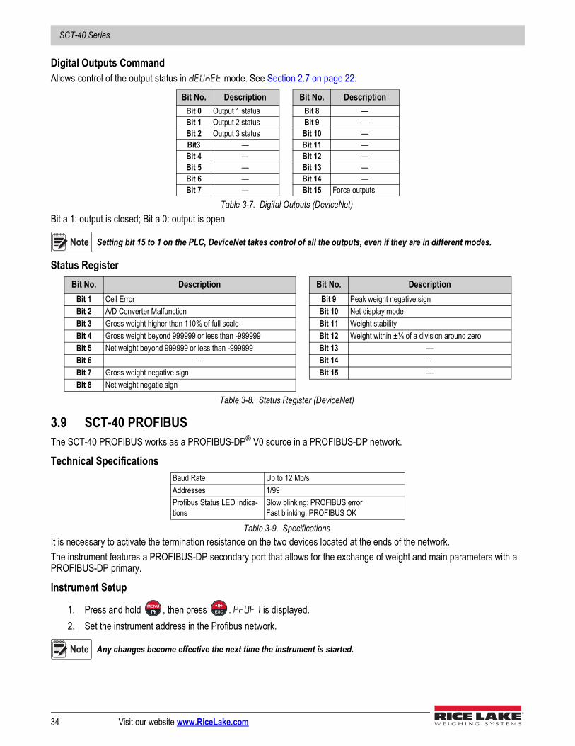
SCT-40 Series
34 Visit our website www.RiceLake.com
Digital Outputs CommandAllows control of the output status in mode. See Section 2.7 on page 22.
Bit a 1: output is closed; Bit a 0: output is open
Setting bit 15 to 1 on the PLC, DeviceNet takes control of all the outputs, even if they are in different modes.
Status Register
3.9 SCT-40 PROFIBUSThe SCT-40 PROFIBUS works as a PROFIBUS-DP® V0 source in a PROFIBUS-DP network.
Technical Specifications
It is necessary to activate the termination resistance on the two devices located at the ends of the network.The instrument features a PROFIBUS-DP secondary port that allows for the exchange of weight and main parameters with a PROFIBUS-DP primary.
Instrument Setup
1. Press and hold , then press . is displayed.2. Set the instrument address in the Profibus network.
Any changes become effective the next time the instrument is started.
Bit No. Description Bit No. DescriptionBit 0 Output 1 status Bit 8 —Bit 1 Output 2 status Bit 9 —Bit 2 Output 3 status Bit 10 —Bit3 — Bit 11 —Bit 4 — Bit 12 —Bit 5 — Bit 13 —Bit 6 — Bit 14 —Bit 7 — Bit 15 Force outputs
Table 3-7. Digital Outputs (DeviceNet)
Bit No. Description Bit No. DescriptionBit 1 Cell Error Bit 9 Peak weight negative signBit 2 A/D Converter Malfunction Bit 10 Net display modeBit 3 Gross weight higher than 110% of full scale Bit 11 Weight stabilityBit 4 Gross weight beyond 999999 or less than -999999 Bit 12 Weight within ±¼ of a division around zeroBit 5 Net weight beyond 999999 or less than -999999 Bit 13 —Bit 6 — Bit 14 —Bit 7 Gross weight negative sign Bit 15 —Bit 8 Net weight negatie sign
Table 3-8. Status Register (DeviceNet)
Baud Rate Up to 12 Mb/sAddresses 1/99Profibus Status LED Indica-tions
Slow blinking: PROFIBUS errorFast blinking: PROFIBUS OK
Table 3-9. Specifications
Note
MENUESC
Note

Operation
© Rice Lake Weighing Systems ● All Rights Reserved 35
PC/PLC SetupLoad the included GSD file (LAU80BBC.gsd) attached to the instrument in the development system of the PROFIBUS primary.Insert and configure the SCT-40 PROFIBUS in an existing project.The available modules are:
• R = the register can be read only• W = the register can be written only• R/W = the register can be both read and written
* 0x00000000 value in writing is ignored. To reset the value, write out 0x80000000**
Setpoints, hysteresis, Zero, and Full Scale weight of analog output are stored to RAM and lost upon instrument power off; to save them in EEPROM so they are maintained upon instrument power on, it is necessary to send the command 99 “Save data in EEPROM” of the Command Register.
Name Description R/W SizeTLM8 Gross Weight Gross Weight R 4 byteTLM8 Net Weight Net Weight R 4 byteTLM8 Peak Weight Peak Weight R 4 byteTLM8 Set-Point 1 Setpoint 1 R/W* 4 byte/4byteTLM8 Set-Point 2 Setpoint 2 R/W* 4 byte/4byteTLM8 Set-Point 3 Setpoint 3 R/W* 4 byte/4byteTLM8 Set-Point 4 Setpoint 4 R/W* 4 byte/4byteTLM8 Set-Point 5 Setpoint 5 R/W* 4 byte/4byteTLM8 Hysteresis 1 Setpoint 1 Hysteresis R/W* 4 byte/4byteTLM8 Hysteresis 2 Setpoint 2 Hysteresis R/W* 4 byte/4byteTLM8 Hysteresis 3 Setpoint 3 Hysteresis R/W* 4 byte/4byteTLM8 Hysteresis 4 Setpoint 4 Hysteresis R/W* 4 byte/4byteTLM8 Hysteresis 5 Setpoint 5 Hysteresis R/W* 4 byte/4byteTLM8 Division/Unit Divisions and Unites of Measure R 2 byteTLM8 Visual Coeff Display Coefficient R 4 byteTLM8 Inputs Inputs Status R 2 byteTLM8 Outputs Outputs Status R/W 2 byte/2 byteTLM8 Status Reg Status Register R 2 byteTLM8 Command Reg Command Register W 2 byteTLM8 Sample Weight Sample Weight R/W* 4 byte/4 byteTLM8 ZeroAn Weight Zero Weight-Analog Output R/W* 4 byte/4 byteTLM8 FSAn Weight Full Scale Weight-Analog Output R/W* 4 byte/4 byteTLM8 Divisions 1** Channel 1 Divisions R 4 byteTLM8 Divisions 2** Channel 2 Divisions R 4 byteTLM8 Divisions 3** Channel 3 Divisions R 4 byteTLM8 Divisions 4** Channel 4 Divisions R 4 byteTLM8 Divisions 5** Channel 5 Divisions R 4 byteTLM8 Divisions 6** Channel 6 Divisions R 4 byteTLM8 Divisions 7** Channel 7 Divisions R 4 byteTLM8 Divisions 8** Channel 8 Divisions R 4 byte
Table 3-10. SCT-40 PROFIBUS Descriptions
Input Signal on Single Channel
Reading Divisions
0 mV 010 mV 2000000-10 mV -2000000
Note
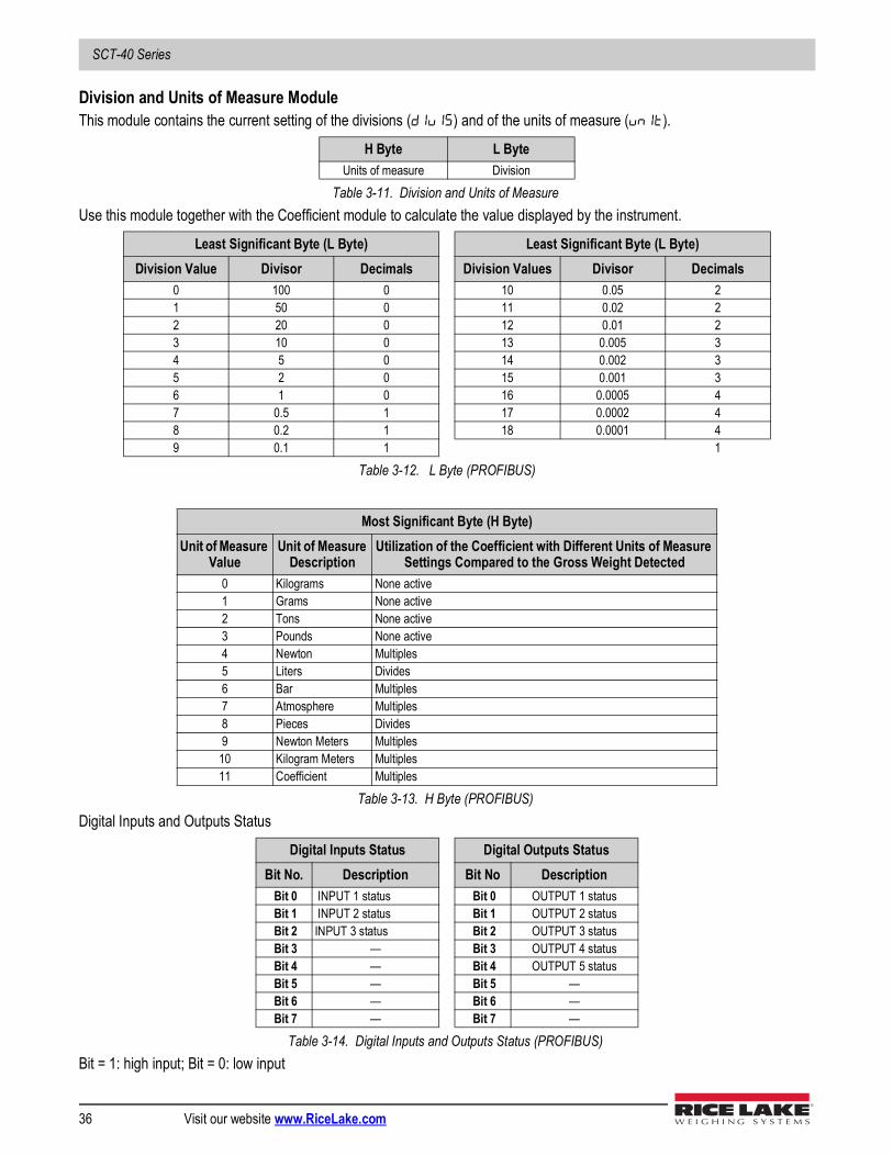
SCT-40 Series
36 Visit our website www.RiceLake.com
Division and Units of Measure ModuleThis module contains the current setting of the divisions () and of the units of measure ().
Use this module together with the Coefficient module to calculate the value displayed by the instrument.
Digital Inputs and Outputs Status
Bit = 1: high input; Bit = 0: low input
H Byte L ByteUnits of measure Division
Table 3-11. Division and Units of Measure
Least Significant Byte (L Byte) Least Significant Byte (L Byte)Division Value Divisor Decimals Division Values Divisor Decimals
0 100 0 10 0.05 21 50 0 11 0.02 22 20 0 12 0.01 23 10 0 13 0.005 34 5 0 14 0.002 35 2 0 15 0.001 36 1 0 16 0.0005 47 0.5 1 17 0.0002 48 0.2 1 18 0.0001 49 0.1 1 1
Table 3-12. L Byte (PROFIBUS)
Most Significant Byte (H Byte)Unit of Measure
ValueUnit of Measure
DescriptionUtilization of the Coefficient with Different Units of Measure
Settings Compared to the Gross Weight Detected0 Kilograms None active1 Grams None active2 Tons None active3 Pounds None active4 Newton Multiples5 Liters Divides6 Bar Multiples7 Atmosphere Multiples8 Pieces Divides9 Newton Meters Multiples
10 Kilogram Meters Multiples11 Coefficient Multiples
Table 3-13. H Byte (PROFIBUS)
Digital Inputs Status Digital Outputs StatusBit No. Description Bit No Description
Bit 0 INPUT 1 status Bit 0 OUTPUT 1 status Bit 1 INPUT 2 status Bit 1 OUTPUT 2 status Bit 2 INPUT 3 status Bit 2 OUTPUT 3 status Bit 3 — Bit 3 OUTPUT 4 status Bit 4 — Bit 4 OUTPUT 5 status Bit 5 — Bit 5 — Bit 6 — Bit 6 — Bit 7 — Bit 7 —
Table 3-14. Digital Inputs and Outputs Status (PROFIBUS)
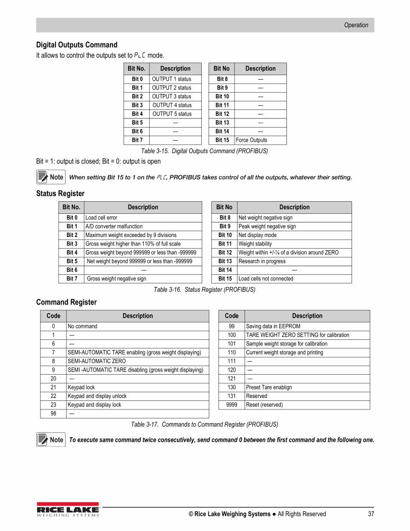
Operation
© Rice Lake Weighing Systems ● All Rights Reserved 37
Digital Outputs CommandIt allows to control the outputs set to mode.
Bit = 1: output is closed; Bit = 0: output is open
When setting Bit 15 to 1 on the , PROFIBUS takes control of all the outputs, whatever their setting.
Status Register
Command Register
To execute same command twice consecutively, send command 0 between the first command and the following one.
Bit No. Description Bit No Description Bit 0 OUTPUT 1 status Bit 8 — Bit 1 OUTPUT 2 status Bit 9 — Bit 2 OUTPUT 3 status Bit 10 — Bit 3 OUTPUT 4 status Bit 11 — Bit 4 OUTPUT 5 status Bit 12 — Bit 5 — Bit 13 — Bit 6 — Bit 14 — Bit 7 — Bit 15 Force Outputs
Table 3-15. Digital Outputs Command (PROFIBUS)
Bit No. Description Bit No Description Bit 0 Load cell error Bit 8 Net weight negative sign Bit 1 A/D converter malfunction Bit 9 Peak weight negative sign Bit 2 Maximum weight exceeded by 9 divisions Bit 10 Net display mode Bit 3 Gross weight higher than 110% of full scale Bit 11 Weight stability Bit 4 Gross weight beyond 999999 or less than -999999 Bit 12 Weight within +/-¼ of a division around ZERO Bit 5 Net weight beyond 999999 or less than -999999 Bit 13 Research in progress Bit 6 — Bit 14 — Bit 7 Gross weight negative sign Bit 15 Load cells not connected
Table 3-16. Status Register (PROFIBUS)
Code Description Code Description0 No command 99 Saving data in EEPROM1 — 100 TARE WEIGHT ZERO SETTING for calibration6 — 101 Sample weight storage for calibration7 SEMI-AUTOMATIC TARE enabling (gross weight displaying) 110 Current weight storage and printing8 SEMI-AUTOMATIC ZERO 111 —9 SEMI -AUTOMATIC TARE disabling (gross weight displaying) 120 —20 — 121 —21 Keypad lock 130 Preset Tare enablign22 Keypad and display unlock 131 Reserved23 Keypad and display lock 9999 Reset (reserved)98 —
Table 3-17. Commands to Command Register (PROFIBUS)
Note
Note

SCT-40 Series
38 Visit our website www.RiceLake.com
Real Calibration Commands (with Sample Weights)The instrument calibration can be changed via PROFIBUS. To perform the edit calibration procedure:
1. Unload the system and then using the command 100 Tare Weight Zero-Setting for calibration of the command register.
1. Ensure the display reads zero.2. Place a sample weight on the scale and send its value to the sample weight module.3. Send zero to the sample weight module.4. Send the command 101 Sample weight storage for calibration to record weight value in the exchange register. If the
operation is successfully completed, the sample weight read is set to zero.
3.10 SCT-40 PROFINET-IOThe SCT-40 PROFINET-IO works as a source device in a PROFINET-IO network. (Ethernet Setup)
• — (default: ). The allows the selection of the reading/writing of the byte in LITTLE-ENDIAN or BIG-ENDIAN mode. = LITTLE ENDIAN, = BIG ENDIAN.
• — (default: 192.8.0.141). Set the instrument IP address; Single port only - see note below• — (default: 255.255.255.0). Set the instrument Subnet Mask.; Single port only - see note below• — (default: 192.8.0.111). Set the Gateway address of Ethernet network; Single port only - see note below
IP Address, Subnet Mask and Gateway Address parameters are configurable through the front panel of a single port device, but not a dual port. For a dual port device, parameters must be set using a PLC software such as Siemens Step 7 or Siemens TIA Portal. If a PLC software is not available, use the software program at the following link: https://kb.hilscher.com/display/ETHDEVCFG/V1.0900.2.3231Changes made to the Ethernet setup, IP address, Subnet Mask, and Gateway settings will not take effect on the device until after a power cycle.
PC/PLC SetupLoad the included XML file (Profinet_40.xml) attached to the instrument in the development system of the PROFINET-IO primary.
• Insert and configure the SCT-40 PROFINET-IO in an existing project.• Using the Assign Device Name function, assign a name to the device using any combination of the following characters
• lower case letters (a-z)• numbers (0-9)• hyphen (-)
• Set the PROFINET- I/O refresh time to at lease 8 milliseconds.The data exchanged by the SCT-40 PROFINET-IO are:
Outgoing Data from SCT-40 PROFINET-IO (Read) Address
Input Data to SCT-40 PROFINET-IO (Write) Address
Internal Status (2 bytes) 0x0000-0x0001 Write Enable (2 bytes) 0x0000-0x0001Gross Weight (4 bytes) 0x0002-0x0005 Command Register (2 bytes) 0x0002-0x0003Net Weight (4 bytes) 0x0006-0x0009 Digital Outputs Command (2 bytes) 0x0004-0x0005Exchange Register (4bytes) 0x000A-0x000D Exchange Register (4 bytes) 0x0006-0x0009Status Register (2 bytes) 0x000E-0x000FDigital Inputs status (2 bytes) 0x0010-0x0011Digital Output status (2 bytes) 0x0012-0x0013
Table 3-18. Single Port Interface – Exchanged Data (PROFINET)
Note
Note
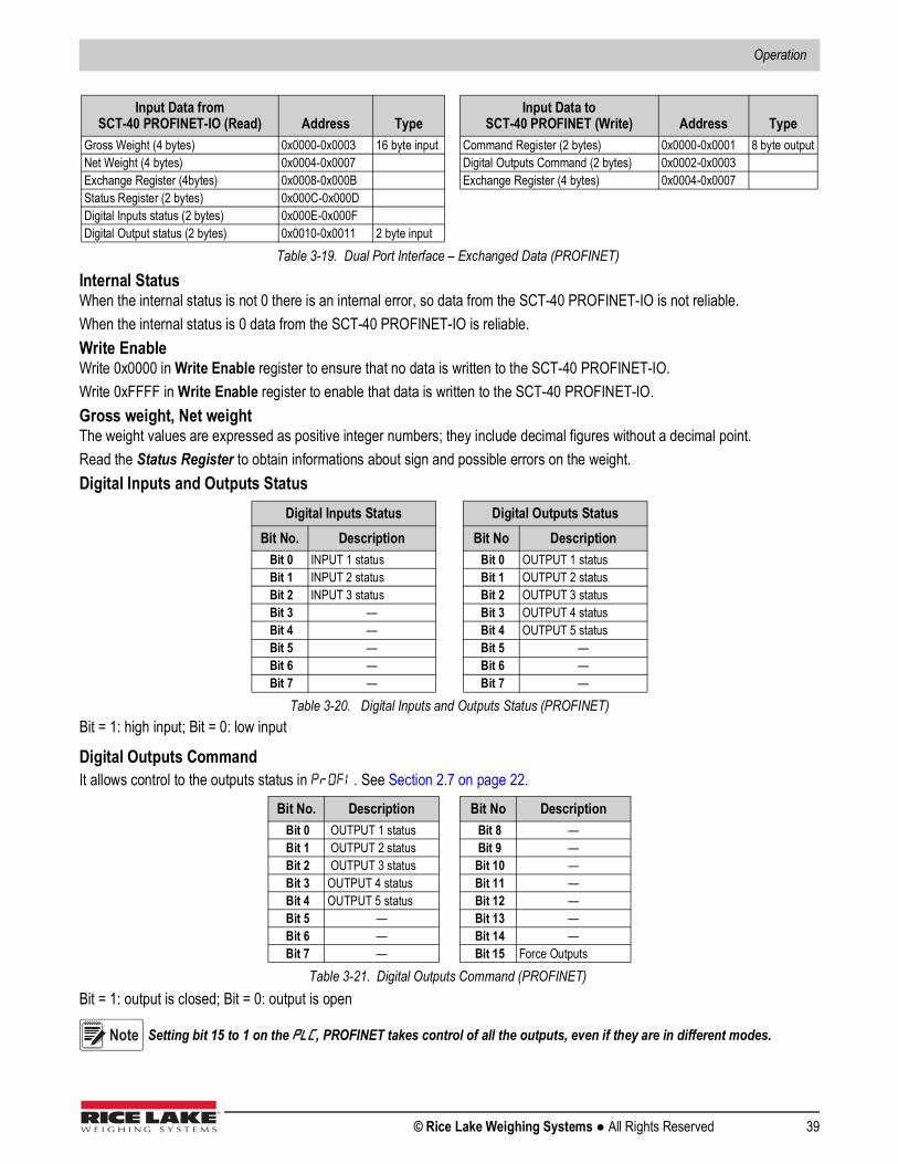
Operation
© Rice Lake Weighing Systems ● All Rights Reserved 39
Internal StatusWhen the internal status is not 0 there is an internal error, so data from the SCT-40 PROFINET-IO is not reliable.When the internal status is 0 data from the SCT-40 PROFINET-IO is reliable.Write EnableWrite 0x0000 in Write Enable register to ensure that no data is written to the SCT-40 PROFINET-IO.Write 0xFFFF in Write Enable register to enable that data is written to the SCT-40 PROFINET-IO.Gross weight, Net weightThe weight values are expressed as positive integer numbers; they include decimal figures without a decimal point. Read the Status Register to obtain informations about sign and possible errors on the weight.Digital Inputs and Outputs Status
Bit = 1: high input; Bit = 0: low input
Digital Outputs CommandIt allows control to the outputs status in . See Section 2.7 on page 22.
Bit = 1: output is closed; Bit = 0: output is open
Setting bit 15 to 1 on the , PROFINET takes control of all the outputs, even if they are in different modes.
Input Data from SCT-40 PROFINET-IO (Read) Address Type
Input Data to SCT-40 PROFINET (Write) Address Type
Gross Weight (4 bytes) 0x0000-0x0003 16 byte input Command Register (2 bytes) 0x0000-0x0001 8 byte outputNet Weight (4 bytes) 0x0004-0x0007 Digital Outputs Command (2 bytes) 0x0002-0x0003Exchange Register (4bytes) 0x0008-0x000B Exchange Register (4 bytes) 0x0004-0x0007Status Register (2 bytes) 0x000C-0x000DDigital Inputs status (2 bytes) 0x000E-0x000FDigital Output status (2 bytes) 0x0010-0x0011 2 byte input
Table 3-19. Dual Port Interface – Exchanged Data (PROFINET)
Digital Inputs Status Digital Outputs StatusBit No. Description Bit No Description
Bit 0 INPUT 1 status Bit 0 OUTPUT 1 status Bit 1 INPUT 2 status Bit 1 OUTPUT 2 status Bit 2 INPUT 3 status Bit 2 OUTPUT 3 status Bit 3 — Bit 3 OUTPUT 4 status Bit 4 — Bit 4 OUTPUT 5 status Bit 5 — Bit 5 — Bit 6 — Bit 6 — Bit 7 — Bit 7 —
Table 3-20. Digital Inputs and Outputs Status (PROFINET)
Bit No. Description Bit No Description Bit 0 OUTPUT 1 status Bit 8 — Bit 1 OUTPUT 2 status Bit 9 — Bit 2 OUTPUT 3 status Bit 10 — Bit 3 OUTPUT 4 status Bit 11 — Bit 4 OUTPUT 5 status Bit 12 — Bit 5 — Bit 13 — Bit 6 — Bit 14 — Bit 7 — Bit 15 Force Outputs
Table 3-21. Digital Outputs Command (PROFINET)
Note

SCT-40 Series
40 Visit our website www.RiceLake.com
Status Register
Command RegisterTable 3-23 shows possible commands to send to the command register: r
To execute the same command twice consecutively, send command 0 between the first command and the following one.
** The SCT-40 PROFINET-IO features two exchange registers one for reading and one for writing. These must be used together with the command register to access these values. Use the following instructions to access these values:
• Reading: send the desired data reading command to the command register and read the content of the exchange register. For example send command 90 for a Setpoint 1 reading.
• Writing: write the value to be set in the exchange register and send the desired data writing command to the command register. For example send command 93 for Setpoint 1 writing.
Bit No. Description Bit No Description Bit 0 Load cell error Bit 8 Net weight negative sign Bit 1 A/D converter malfunction Bit 9 Peak weight negative sign Bit 2 Maximum weight exceeded by 9 divisions Bit 10 Net display mode Bit 3 Gross weight higher than 110% of full scale Bit 11 Weight stability Bit 4 Gross weight beyond 999999 or less than -999999 Bit 12 Weight within +/-¼ of a division around ZERO Bit 5 Net weight beyond 999999 or less than -999999 Bit 13 Research in progress Bit 6 — Bit 14 — Bit 7 Gross weight negative sign Bit 15 Load cells not connected
Table 3-22. Status Register (PROFINET)
Code Description Code Description0 No command 90 Setpoint 1 reading**7 Net weight display 91 Setpoint 2 reading**8 Semi-automatic zero 92 Setpoint 3 reading**9 Gross weight display 93 Setpoint 1 writing**21 Keypad lock 94 Setpoint 2 writing**22 Keypad and display unlock 95 Setpoint 3 writing**23 Keypad and display lock 99 Save data in EEPROM24 Mode: 8x divisions LowRes 100 Zero-setting for calibration25 Mode: 4x divisions HiRes (ch1-4) 101 Sample weight storage for calibration26 Mode: 4x divisions HiRes (ch 5-8) 102 Sample weight reading**27 Mode: standard 103 Sample weight writing**87 Preset tare reading** 110 Current weight storage and printing88 Preset tare writing** 130 Preset tare enable
150 Setpoint 4 reading**151 Sepoint 5 reading**160 Setpoint 4 writing**161 Setpoint 5 writing**
9999 Reset (reserved)
Table 3-23. Commands to Command Register (PROFINET)
Note

Operation
© Rice Lake Weighing Systems ● All Rights Reserved 41
Use this information with commands 24, 25, 26 and 27 of the command register.
Mode: 8x divisions Low ResolutionSend command 24 to the command register to modify the SCT-40 PROFINET-IO output data so that the low resolution (16bit) values of all 8 channels divisions are reported.
Mode: 4x divisions High Resolution (ch 1-4)Send command 25 to the command register to modify the SCT-40 PROFINET-IO output data so that the high resolution (24 bits) values of the first four channels divisions are reported.
Mode: 4x divisions High Resolution (ch 5-8)Send command 26 to the command register to modify the SCT-40 PROFINET-IO output data so that the high resolution (24 bits) values of the second 4 channels divisions are reported as shown in Table 3-27.
Mode: standardSend command 27 to command register to modify the SCT-40 PROFINET-IO output data so that the original data is reported.
Input Signal on Single Channel
Low Resolution
High Resolution
0 mV 0 010 mV 8000 2000000-10 mV -8000 -2000000
Table 3-24. Reading Divisions
Output Data from SCT-40 PROFINET-IO (Reading) AddressInternal Status (2 byte) 0x0000-0x0001Channel 1 reading divisions - Low Res (2 bytes) 0x0002-0x0003Channel 2 reading divisions - Low Res (2 bytes) 0x0004-0x00005Channel 3 reading divisions - Low Res (2 bytes) 0x0006-0x0007Channel 4 reading divisions - Low Res (2 bytes) 0x0008-0x0009Channel 5 reading divisions - Low Res (2 bytes) 0x000A-0x000BChannel 6 reading divisions - Low Res (2 bytes) 0x000C-0x000DChannel 7 reading divisions - Low Res (2 bytes) 0x000E-0x000FChannel 8 reading divisions - Low Res (2 bytes) 0x0010-0x0011Status Register (2 bytes) 0x0012-0x0013
Table 3-25. 8x Divisions Low Res
Output Data from SCT-40 PROFINET-IO (Reading) AddressInternal Status (2 byte) 0x0000-0x0001Channel 1 reading divisions - HIgh Res (4 bytes) 0x0002-0x0005Channel 2 reading divisions - HIgh Res (4 bytes) 0x0006-0x00009Channel 3 reading divisions - HIgh Res (4 bytes) 0x000A-0x000DChannel 4 reading divisions - HIgh Res (4 bytes) 0x000E-0x00011Status Register (2 bytes) 0x0012-0x0013
Table 3-26. 4x Divisions High Res (ch 1-4)
Output Data from SCT-40 PROFINET-IO (Reading) AddressInternal Status (2 byte) 0x0000-0x0001Channel 5 reading divisions - High Res (2 bytes) 0x0002-0x0005Channel 6 reading divisions - High Res (2 bytes) 0x0006-0x0009Channel 7 reading divisions - HIgh Res (2 bytes) 0x000A-0x000DChannel 8 reading divisions - HIgh Res (2 bytes) 0x00E-0x0011Status Register (2 bytes) 0x0012-0x0013
Table 3-27. 4x Divisions High Res (ch 5-8)

SCT-40 Series
42 Visit our website www.RiceLake.com
Setpoints – HysteresisThe weight values are expressed as positive integer numbers; they include decimal figures without a decimal point.
• Reading: send the desired data reading command to the command register and read the content of the exchange register. For example send command 90 for a Setpoint 1 reading.
• Writing: write the value to be set in the exchange register and send the desired data writing command to the command register. For example send command 93 for Setpoint 1 writing.
Setpoints and Hysteresis are stored to the RAM volatile memory and lost upon instrument power off. To save them permanently in the EEPROM memory, so that they are maintained upon the instrument power on, it is necessary to send the command 99 Save data in EEPROM of the command register.
Real Calibration Commands (With Sample Weight)The SCT-40 PROFINET-IO calibration can be changed via PROFINET.To correctly set the sample weight, the value of the division module must be taken into consideration.
Example: to set the value to 100kg and the division value is 0.001, set the register value to 100000 (remove the decimal points from the value that would be 100.000 with decimals).
To perform the edit calibration procedure: 1. Unload the system, then using the command 100 Tare Weight Zero-Setting for calibration of the command register,
ensure the display reads zero.2. Place a sample weight on the scale.3. Record the correct known weight value in the exchange register.4. Send the command 103 Sample weight storage for calibration.5. To save the value, send the command 101 Sample weight storage for calibration to the command register.6. Send the command 102 Sample weight storage to the command register. A returned value of zero verifies the correct
execution of the calibration command. See Table 3-23 on page 40 for a list of PROFINET commands.
Changing some instrument parameters via keyboard can take the PROFIBUS network out of the data exchange status and put the in stop status; when programming the instrument it is recommended that the instrument is off-line or in a stand-by status.
Note
Note
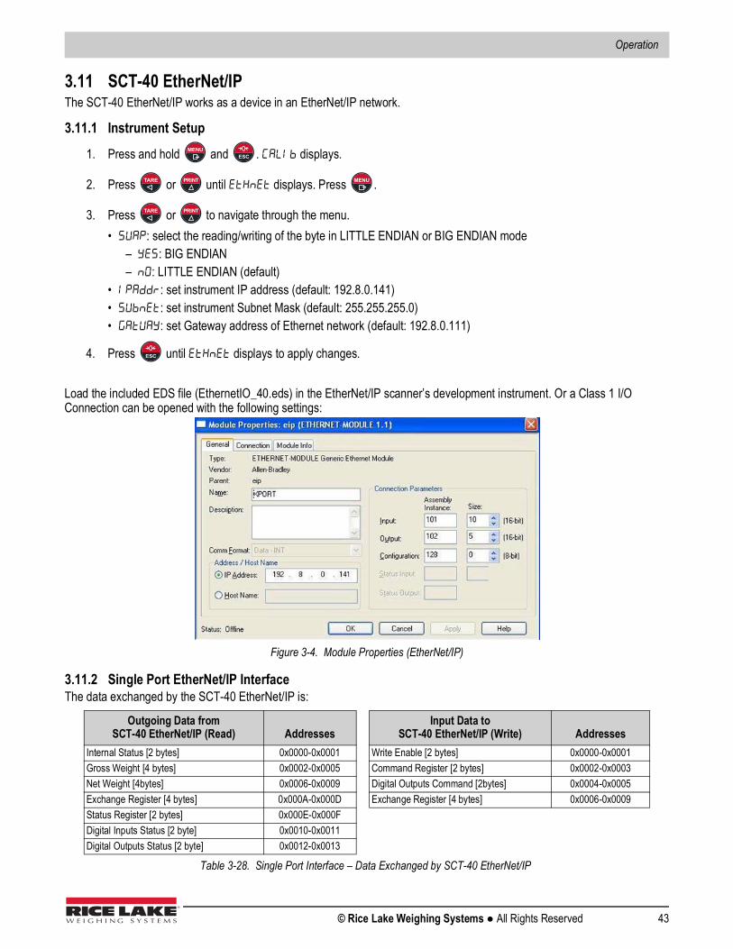
Operation
© Rice Lake Weighing Systems ● All Rights Reserved 43
3.11 SCT-40 EtherNet/IPThe SCT-40 EtherNet/IP works as a device in an EtherNet/IP network.
3.11.1 Instrument Setup
1. Press and hold and . displays.
2. Press or until displays. Press .
3. Press or to navigate through the menu.• : select the reading/writing of the byte in LITTLE ENDIAN or BIG ENDIAN mode – : BIG ENDIAN – : LITTLE ENDIAN (default)• : set instrument IP address (default: 192.8.0.141)• : set instrument Subnet Mask (default: 255.255.255.0)• : set Gateway address of Ethernet network (default: 192.8.0.111)
4. Press until displays to apply changes.
Load the included EDS file (EthernetIO_40.eds) in the EtherNet/IP scanner’s development instrument. Or a Class 1 I/O Connection can be opened with the following settings:
Figure 3-4. Module Properties (EtherNet/IP)
3.11.2 Single Port EtherNet/IP InterfaceThe data exchanged by the SCT-40 EtherNet/IP is:
Outgoing Data from SCT-40 EtherNet/IP (Read) Addresses
Input Data to SCT-40 EtherNet/IP (Write) Addresses
Internal Status [2 bytes] 0x0000-0x0001 Write Enable [2 bytes] 0x0000-0x0001Gross Weight [4 bytes] 0x0002-0x0005 Command Register [2 bytes] 0x0002-0x0003Net Weight [4bytes] 0x0006-0x0009 Digital Outputs Command [2bytes] 0x0004-0x0005Exchange Register [4 bytes] 0x000A-0x000D Exchange Register [4 bytes] 0x0006-0x0009Status Register [2 bytes] 0x000E-0x000FDigital Inputs Status [2 byte] 0x0010-0x0011Digital Outputs Status [2 byte] 0x0012-0x0013
Table 3-28. Single Port Interface – Data Exchanged by SCT-40 EtherNet/IP
MENUESC
TARE PRINT MENU
TARE PRINT
ESC

SCT-40 Series
44 Visit our website www.RiceLake.com
3.11.3 Dual Port EtherNet/IP InterfaceDual port interface uses a different configuration file compared to the single port, making the connection parameters different between the two outputs.
EDS File SetupThe configuration used when setting up a devise with the EDS file.
Generic EtherNet/IP Module SetupThe configuration used when setting up a devise with the generic module file.
Figure 3-5. Dual Port – Generic EtherNet/IP Module Setup
Outgoing Data fromSCT-40 EtherNet/IP (Read) Addresses Type
Input Data toSCT-40 EtherNet/IP (Write) Addresses Type
Gross Weight [4 bytes] 0x0000-0x0003 Double Integer Command Register [2 bytes] 0x0000-0x0001 IntegerNet Weight [4bytes] 0x0004-0x0007 Double Integer Digital Outputs Command [2bytes] 0x0002-0x0003 IntegerExchange Register [4 bytes] 0x0008-0x000B Double Integer Exchange Register [4 bytes] 0x0004-0x0007 Double IntegerStatus Register [2 bytes] 0x000C-0x000D IntegerDigital Inputs Status [2 byte] 0x000E-0x000F IntegerDigital Outputs Status [2 byte] 0x0010-0x0011 Integer
Table 3-29. EDS Output Data – Dual Port Interface (EtherNet/IP)
Outgoing Data fromSCT-40 EtherNet/IP (Read) Addresses Type
Input Data toSCT-40 EtherNet/IP (Write) Addresses Type
Header Information [4 bytes] 0x0000-0x0003 Double Integer Command Register [2 bytes] 0x0000-0x0001 IntegerGross Weight [4 bytes] 0x0004-0x0007 Double Integer Digital Outputs Command [2bytes] 0x0002-0x0003 IntegerNet Weight [4bytes] 0x0008-0x000B Double Integer Exchange Register [4 bytes] 0x0004-0x0007 Double IntegerExchange Register [4 bytes] 0x000C-0x000F Double IntegerStatus Register [2 bytes] 0x0010-0x0011 IntegerDigital Inputs Status [2 byte] 0x0012-0x0013 IntegerDigital Outputs Status [2 byte] 0x0014-0x0015 Integer
Table 3-30. Generic Module Output Data – Dual Port Interface (EtherNet/IP)

Operation
© Rice Lake Weighing Systems ● All Rights Reserved 45
Command Register
To execute the same command twice consecutively, send command 0 between first command and the following one.
Internal StatusWhen the internal status is not 0 there is an internal error, so data from the SCT-40 EtherNet/IP is not reliable.When the internal status is 0 data from the SCT-40 EtherNet/IP is reliable.
Header InformationThe header information value must be a 1, if it is a 0 then the SCT-40 needs to be replaced.
Write EnableWrite 0x0000 in Write Enable register to ensure that no data is written to the SCT-40 EtherNet/IP.Write 0xFFFF in Write Enable register to enable that data is written to the SCT-40 EtherNet/IP.
Gross weight, Net weightThe weight values are expressed as positive integer numbers; they include decimal figures without a decimal point. Read the Status Register to obtain informations about sign and possible errors on the weight.
SetpointsThe setpoints are weight values expressed as positive integer numbers; they include decimal figures without a decimal point.
• Reading: send to the command register the reading command of the required setpoint and read the content of the Setpoint Register
Example: 90 for reading setpoint 1 • Writing: write the weight value to be set in the setpoint and send to the command register the writing command of the
required setpoint Example: 93 for writing setpoint 1
Setpoints are stored to the RAM volatile memory; they are lost upon instrument power off. To save them permanently in the EEPROM memory, so that they are maintained upon the instrument power on. It is necessary to send the command 99 Save data in EEPROM to the command register.
Bit a 1: input high; Bit a 0: input is low
Code Description Code Description 0 No command 90 Read setpoint 1 7 Semi-automatic tare (NET display) 91 Read setpoint 2 8 SEMI-AUTOMATIC ZERO 92 Read setpoint 3 9 GROSS display 93 Write setpoint 1
21 Keypad lock 94 Write setpoint 2 22 Keypad and display unlock 95 Write setpoint 3 23 Keypad and display lock 99 Save data in EEPROM
9999 Reset (reserved)
Table 3-31. Commands to Command Register (EtherNet/IP)
Digital Input Status Digital Output Status
Bit No. Description Bit No. Description Bit No. Description Bit No. DescriptionBit 0 INPUT 1 status Bit 4 — Bit 0 OUTPUT 1 status Bit 4 —Bit 1 INPUT 2 status Bit 5 — Bit 1 OUTPUT 2 status Bit 5 —Bit 2 — Bit 6 — Bit 2 OUTPUT 3 status Bit 6 —
Bit 3 — Bit 7 —
Table 3-32. Digital Status (EtherNet/IP)
Note
Note

SCT-40 Series
46 Visit our website www.RiceLake.com
Command RegisterPossible commands to send to command register allowing control to the outputs status in mode (Section 2.7 on page 22):
Bit a 1: output is closed; Bit a 0: output is open.
Setting bit 15 to 1 on the , DeviceNet takes control of all the outputs, even if they are in different modes.
Status Register
Bit No. Description Bit No. Description Bit 0 OUTPUT 1 status Bit 8 Bit 1 OUTPUT 2 status Bit 9 Bit 2 OUTPUT 3 status Bit 10 Bit 3 — Bit 11 Bit 4 Bit 12 Bit 5 Bit 13 Bit 6 Bit 14 Bit 7 Bit 15 Force Outputs
Table 3-33. Commands Sent to Command Register (EtherNet/IP)
Bit No. Description Bit No Description Bit 0 Cell Error Bit 8 Net weight negative sign Bit 1 A/D Converter Malfunction Bit 9 Peak weight negative sign Bit 2 Maximum weight exceeded by 9 divisions Bit 10 Net display mode Bit 3 Gross weight higher than 110% of full scale Bit 11 Weight stability Bit 4 Gross weight beyond 999999 or less than -999999 Bit 12 Weight within +/-¼ of a division around ZERO Bit 5 Net weight beyond 999999 or less than -999999 Bit 13 — Bit 6 — Bit 14 — Bit 7 Gross weight negative sign Bit 15 —
Table 3-34. Status Register (EtherNet/IP)
Note

Operation
© Rice Lake Weighing Systems ● All Rights Reserved 47
3.12 SCT-40 Ethernet TCP/IPTo configure Ethernet TCP/IP port of the SCT-40 TCP/IP, the Lantronix DeviceInstaller must be installed on a Windows PC.
1. Connect the PC and the SCT-40 TCP/IP through a LAN (point-to-point or with hub/switch), and then launch the Lantronix DeviceInstaller, (file DevInst.exe on the CD).
Figure 3-6. Find SCT-40 TCP/IP in LAN2. Select Search and the application will find the SCT-40 TCP/IP in the LAN.
Figure 3-7. Telnet Configuration3. Select the device and select Telnet Configuration.4. Select Connect and press Enter.5. Select 0 Server and change only the IP Address four fields. Do not change other parameters. 6. Press Enter to confirm.
It is strongly recommended to set a fixed IP Address.
7. Select 1 Channel 1, to change serial BaudRate of the Ethernet Module to match the BaudRate set in the SCT-40 TCP/IP Protocol Selection (default 9600). Do not change other parameters.
8. Press Enter to confirm.
Note
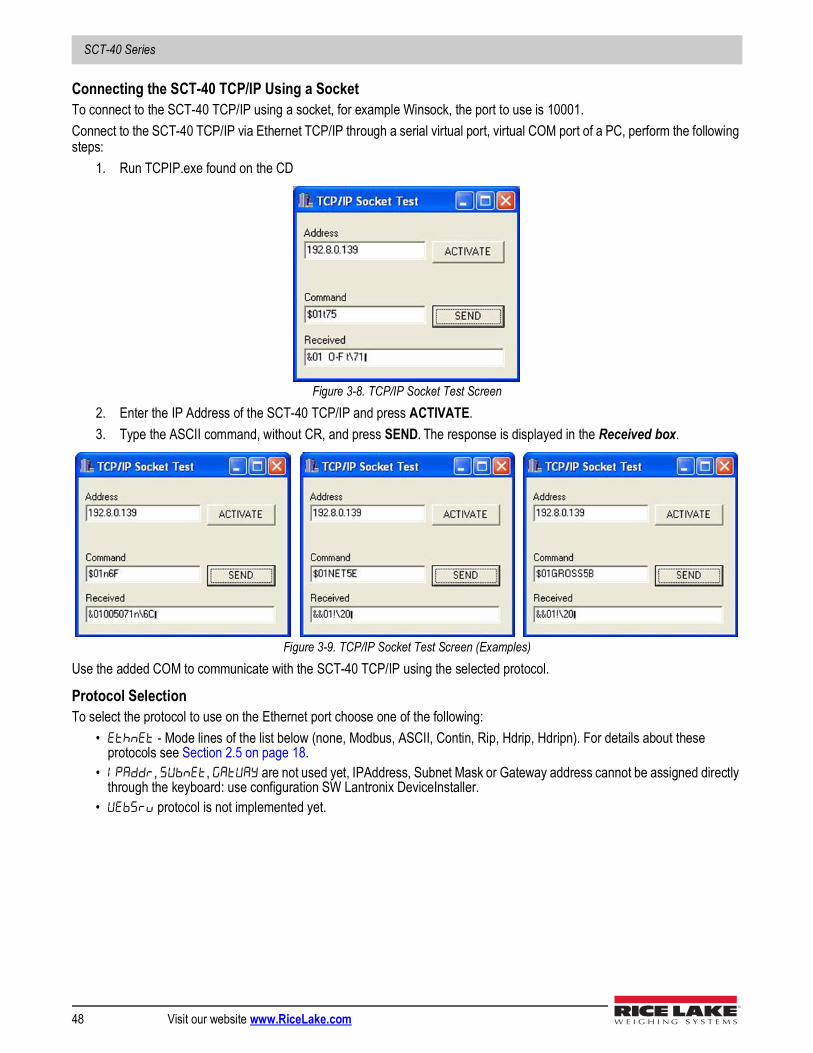
SCT-40 Series
48 Visit our website www.RiceLake.com
Connecting the SCT-40 TCP/IP Using a Socket To connect to the SCT-40 TCP/IP using a socket, for example Winsock, the port to use is 10001.Connect to the SCT-40 TCP/IP via Ethernet TCP/IP through a serial virtual port, virtual COM port of a PC, perform the following steps:
1. Run TCPIP.exe found on the CD
Figure 3-8. TCP/IP Socket Test Screen2. Enter the IP Address of the SCT-40 TCP/IP and press ACTIVATE. 3. Type the ASCII command, without CR, and press SEND. The response is displayed in the Received box.
Figure 3-9. TCP/IP Socket Test Screen (Examples)Use the added COM to communicate with the SCT-40 TCP/IP using the selected protocol.
Protocol SelectionTo select the protocol to use on the Ethernet port choose one of the following:
• - Mode lines of the list below (none, Modbus, ASCII, Contin, Rip, Hdrip, Hdripn). For details about these protocols see Section 2.5 on page 18.
• , , are not used yet, IPAddress, Subnet Mask or Gateway address cannot be assigned directly through the keyboard: use configuration SW Lantronix DeviceInstaller.
• protocol is not implemented yet.
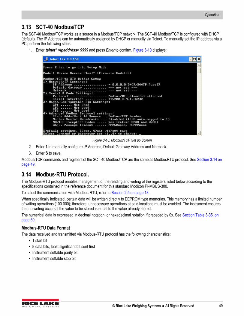
Operation
© Rice Lake Weighing Systems ● All Rights Reserved 49
3.13 SCT-40 Modbus/TCPThe SCT-40 Modbus/TCP works as a source in a Modbus/TCP network. The SCT-40 Modbus/TCP is configured with DHCP (default). The IP Address can be automatically assigned by DHCP or manually via Telnet. To manually set the IP address via a PC perform the following steps.
1. Enter telnet” <ipaddress> 9999 and press Enter to confirm. Figure 3-10 displays:
Figure 3-10. Modbus/TCP Set up Screen2. Enter 1 to manually configure IP Address, Default Gateway Address and Netmask.3. Enter S to save.
Modbus/TCP commands and registers of the SCT-40 Modbus/TCP are the same as ModbusRTU protocol. See Section 3.14 on page 49.
3.14 Modbus-RTU Protocol.The Modbus-RTU protocol enables management of the reading and writing of the registers listed below according to the specifications contained in the reference document for this standard Modicon PI-MBUS-300.To select the communication with Modbus-RTU, refer to Section 2.5 on page 18.When specifically indicated, certain data will be written directly to EEPROM type memories. This memory has a limited number of writing operations (100.000); therefore, unnecessary operations at said locations must be avoided. The instrument ensures that no writing occurs if the value to be stored is equal to the value already stored.The numerical data is expressed in decimal notation, or hexadecimal notation if preceded by 0x. See Section Table 3-35. on page 50.
Modbus-RTU Data FormatThe data received and transmitted via Modbus-RTU protocol has the following characteristics:
• 1 start bit• 8 data bits, least significant bit sent first• Instrument settable parity bit• Instrument settable stop bit
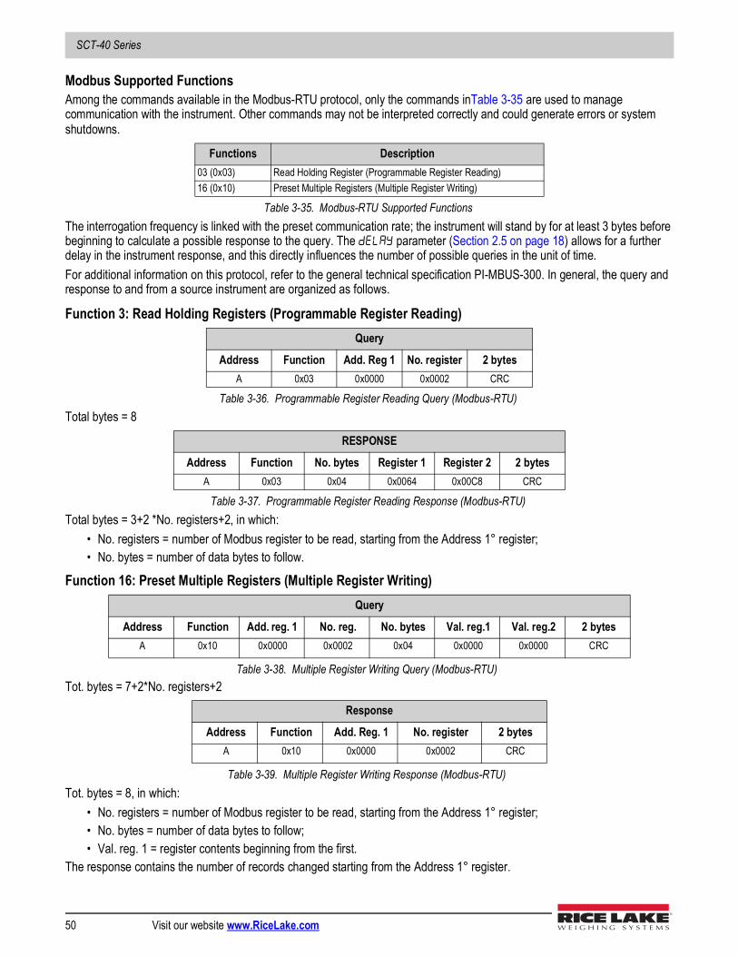
SCT-40 Series
50 Visit our website www.RiceLake.com
Modbus Supported FunctionsAmong the commands available in the Modbus-RTU protocol, only the commands inTable 3-35 are used to manage communication with the instrument. Other commands may not be interpreted correctly and could generate errors or system shutdowns.
The interrogation frequency is linked with the preset communication rate; the instrument will stand by for at least 3 bytes before beginning to calculate a possible response to the query. The parameter (Section 2.5 on page 18) allows for a further delay in the instrument response, and this directly influences the number of possible queries in the unit of time.For additional information on this protocol, refer to the general technical specification PI-MBUS-300. In general, the query and response to and from a source instrument are organized as follows.
Function 3: Read Holding Registers (Programmable Register Reading)
Total bytes = 8
Total bytes = 3+2 *No. registers+2, in which:• No. registers = number of Modbus register to be read, starting from the Address 1° register;• No. bytes = number of data bytes to follow.
Function 16: Preset Multiple Registers (Multiple Register Writing)
Tot. bytes = 7+2*No. registers+2
Tot. bytes = 8, in which: • No. registers = number of Modbus register to be read, starting from the Address 1° register;• No. bytes = number of data bytes to follow;• Val. reg. 1 = register contents beginning from the first.
The response contains the number of records changed starting from the Address 1° register.
Functions Description03 (0x03) Read Holding Register (Programmable Register Reading)16 (0x10) Preset Multiple Registers (Multiple Register Writing)
Table 3-35. Modbus-RTU Supported Functions
Query
Address Function Add. Reg 1 No. register 2 bytesA 0x03 0x0000 0x0002 CRC
Table 3-36. Programmable Register Reading Query (Modbus-RTU)
RESPONSE
Address Function No. bytes Register 1 Register 2 2 bytesA 0x03 0x04 0x0064 0x00C8 CRC
Table 3-37. Programmable Register Reading Response (Modbus-RTU)
Query
Address Function Add. reg. 1 No. reg. No. bytes Val. reg.1 Val. reg.2 2 bytes A 0x10 0x0000 0x0002 0x04 0x0000 0x0000 CRC
Table 3-38. Multiple Register Writing Query (Modbus-RTU)
Response
Address Function Add. Reg. 1 No. register 2 bytes A 0x10 0x0000 0x0002 CRC
Table 3-39. Multiple Register Writing Response (Modbus-RTU)

Operation
© Rice Lake Weighing Systems ● All Rights Reserved 51
Communication Error ManagementThe communication strings are controlled by CRC (Cyclical Redundancy Check).In the event of a communication error, the source will not respond with any string. The primary must allow for a time-out before response reception. If no response is received, it infers that a communication error has occurred.In the event of a string received correctly but not executable, the source responds with an Exceptional Response. The function field is transmitted with the msb at 1.
List of Usable RegistersThe Modbus-RTU protocol implemented on the instrument can manage a maximum of 32 registers read and written in a single query or response. See Table 3-42.
• R = the register can be read only• W = the register can be written only• R/W = the register can be both read and written• H = high half of the DOUBLE WORD forming the number• L = low half of the DOUBLE WORD forming the number
Exceptional Response
Address Function Code 2 bytesA Funct = 0x80 See Table 3-39 CRC
Table 3-40. Exceptional Response (Modbus-RTU)
Code Description1 Illegal function: (function not valid or not supported).2 Illegal data address: (specified data address is not available).3 Illegal data value: (data received have no valid value).
Table 3-41. Exceptional Response Codes (Modbus-RTU)
Register Description Saving to EEPROM Access40001 Firmware version — R40002 Type of instrument — R40003 Year of Production — R40004 Serial Number — R40005 Active program — R40006 COMMAND REGISTER (Table 3-46 on page 54) NO W40007 STATUS REGISTER ( Table 3-43 on page 53) — R40008 GROSS WEIGHT H — R40009 GROSS WEIGHT L — R40010 NET WEIGHT H — R40011 NET WEIGHT L — R40012 PEAK WEIGHT H — RR40013 PEAK WEIGHT L — R40014 Divisions and Units of measure (Table 3-45 on page 54) — R40015 Coefficient H — R40016 Coefficient L — R
Table 3-42. Usable Registers (Modbus-RTU)
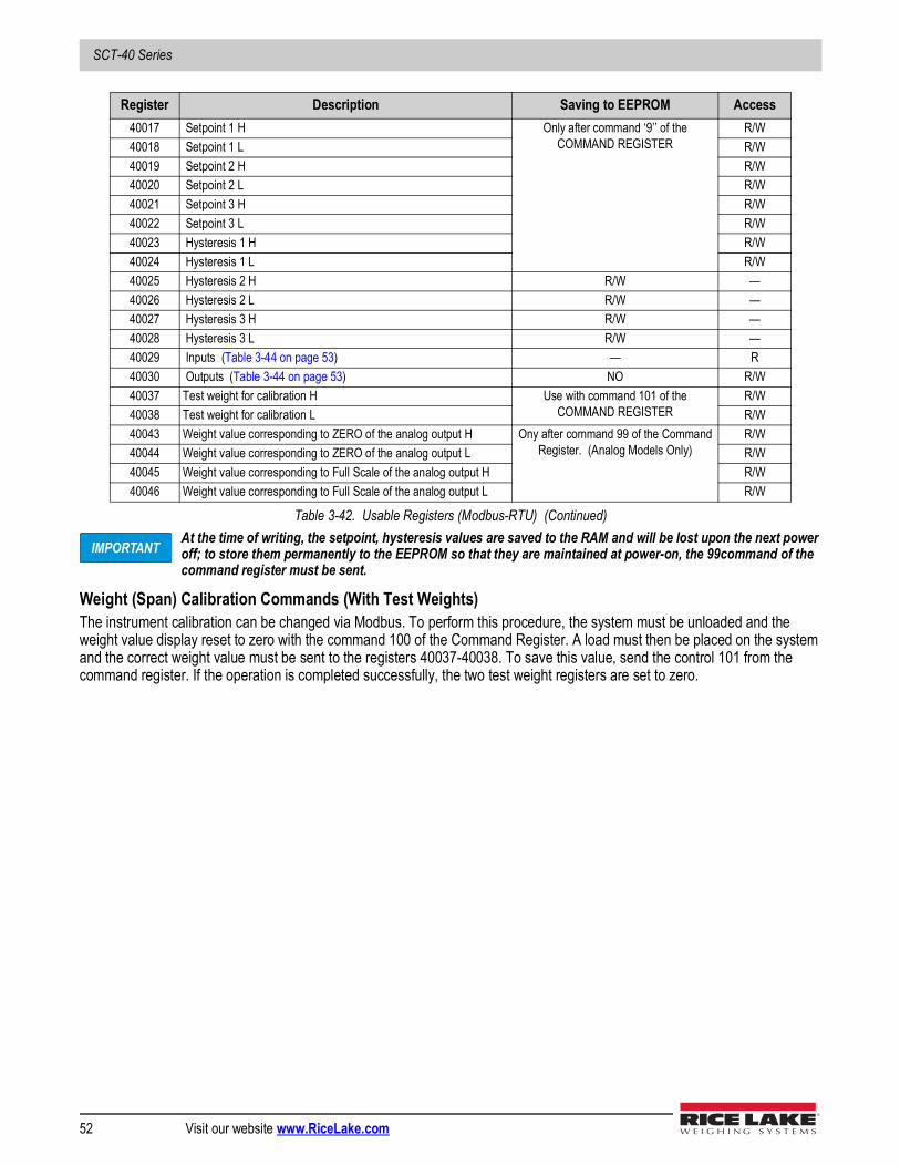
SCT-40 Series
52 Visit our website www.RiceLake.com
At the time of writing, the setpoint, hysteresis values are saved to the RAM and will be lost upon the next power off; to store them permanently to the EEPROM so that they are maintained at power-on, the 99command of the command register must be sent.
Weight (Span) Calibration Commands (With Test Weights)The instrument calibration can be changed via Modbus. To perform this procedure, the system must be unloaded and the weight value display reset to zero with the command 100 of the Command Register. A load must then be placed on the system and the correct weight value must be sent to the registers 40037-40038. To save this value, send the control 101 from the command register. If the operation is completed successfully, the two test weight registers are set to zero.
40017 Setpoint 1 H Only after command ‘9’’ of the COMMAND REGISTER
R/W40018 Setpoint 1 L R/W40019 Setpoint 2 H R/W40020 Setpoint 2 L R/W40021 Setpoint 3 H R/W40022 Setpoint 3 L R/W40023 Hysteresis 1 H R/W40024 Hysteresis 1 L R/W40025 Hysteresis 2 H R/W —40026 Hysteresis 2 L R/W —40027 Hysteresis 3 H R/W —40028 Hysteresis 3 L R/W —40029 Inputs (Table 3-44 on page 53) — R40030 Outputs (Table 3-44 on page 53) NO R/W40037 Test weight for calibration H Use with command 101 of the
COMMAND REGISTERR/W
40038 Test weight for calibration L R/W40043 Weight value corresponding to ZERO of the analog output H Ony after command 99 of the Command
Register. (Analog Models Only)R/W
40044 Weight value corresponding to ZERO of the analog output L R/W40045 Weight value corresponding to Full Scale of the analog output H R/W40046 Weight value corresponding to Full Scale of the analog output L R/W
Register Description Saving to EEPROM Access
Table 3-42. Usable Registers (Modbus-RTU) (Continued)
IMPORTANT
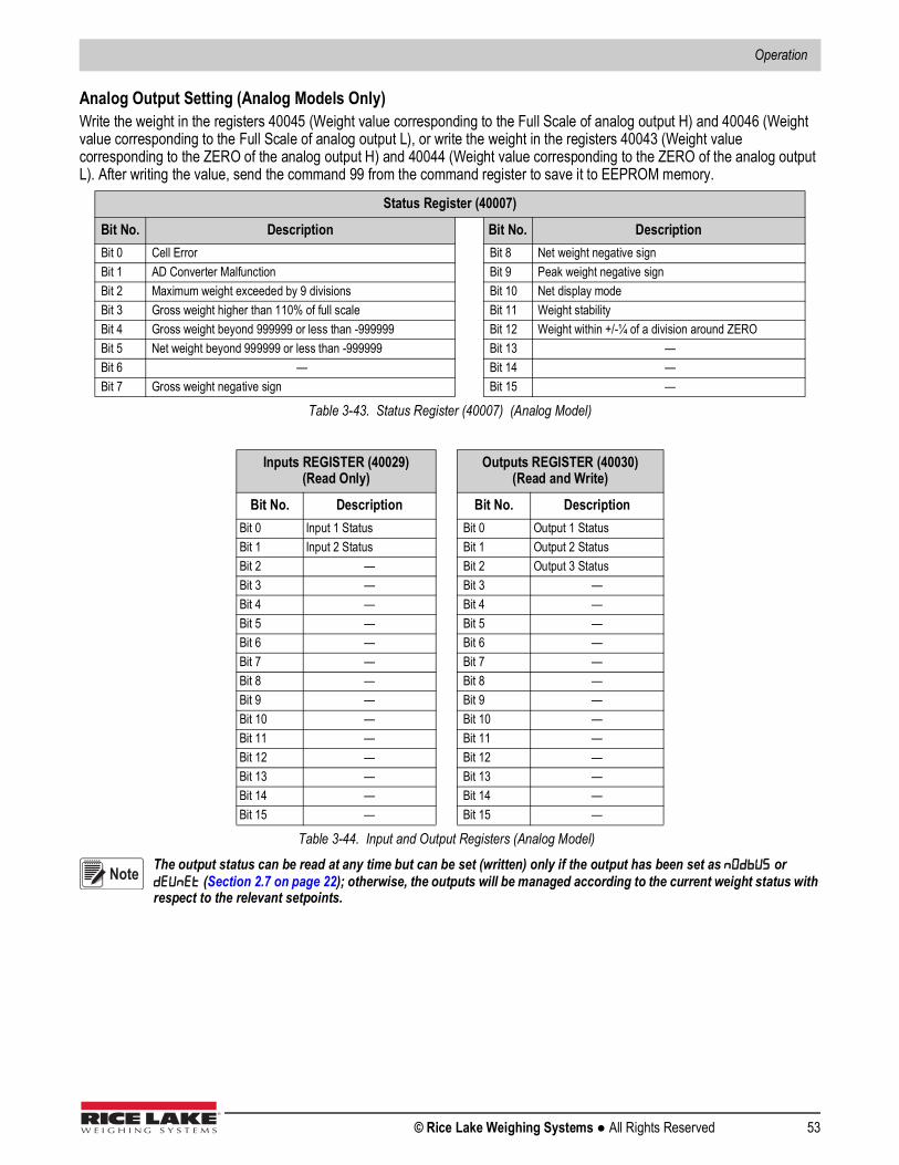
Operation
© Rice Lake Weighing Systems ● All Rights Reserved 53
Analog Output Setting (Analog Models Only)Write the weight in the registers 40045 (Weight value corresponding to the Full Scale of analog output H) and 40046 (Weight value corresponding to the Full Scale of analog output L), or write the weight in the registers 40043 (Weight value corresponding to the ZERO of the analog output H) and 40044 (Weight value corresponding to the ZERO of the analog output L). After writing the value, send the command 99 from the command register to save it to EEPROM memory.
The output status can be read at any time but can be set (written) only if the output has been set as or (Section 2.7 on page 22); otherwise, the outputs will be managed according to the current weight status with respect to the relevant setpoints.
Status Register (40007)
Bit No. Description Bit No. Description Bit 0 Cell Error Bit 8 Net weight negative sign Bit 1 AD Converter Malfunction Bit 9 Peak weight negative sign Bit 2 Maximum weight exceeded by 9 divisions Bit 10 Net display mode Bit 3 Gross weight higher than 110% of full scale Bit 11 Weight stability Bit 4 Gross weight beyond 999999 or less than -999999 Bit 12 Weight within +/-¼ of a division around ZERO Bit 5 Net weight beyond 999999 or less than -999999 Bit 13 — Bit 6 — Bit 14 — Bit 7 Gross weight negative sign Bit 15 —
Table 3-43. Status Register (40007) (Analog Model)
Inputs REGISTER (40029)(Read Only)
Outputs REGISTER (40030)(Read and Write)
Bit No. Description Bit No. DescriptionBit 0 Input 1 Status Bit 0 Output 1 Status Bit 1 Input 2 Status Bit 1 Output 2 Status Bit 2 — Bit 2 Output 3 Status Bit 3 — Bit 3 —Bit 4 — Bit 4 —Bit 5 — Bit 5 —Bit 6 — Bit 6 —Bit 7 — Bit 7 —Bit 8 — Bit 8 —Bit 9 — Bit 9 —Bit 10 — Bit 10 —Bit 11 — Bit 11 —Bit 12 — Bit 12 —Bit 13 — Bit 13 —Bit 14 — Bit 14 —Bit 15 — Bit 15 —
Table 3-44. Input and Output Registers (Analog Model)
Note

SCT-40 Series
54 Visit our website www.RiceLake.com
Divisions and Units of Measure Registry (40014)This register contains the current setting of the divisions parameter () and of the units of measure parameter ().Use this register together with the registers to calculate the value displayed by the instrument.
Command RegisterPossible commands to send to command register (40006).
Least significant byteL Byte (Division)
Most significant byteH Byte (Units of Measure)
Division value Divisor Decimals
Units of measure value
Units of measure description
Utilization of the Coefficient value with the different units of measure settings
compared to the gross weight detected
0 100 0 0 Kilograms Does not intervene 1 50 0 1 Grams Does not intervene 2 20 0 2 Tons Does not intervene 3 10 0 3 Pounds Does not intervene 4 5 0 4 Newton Multiples 5 2 0 5 Liters Divides 6 1 0 6 Bar Multiples 7 0.5 1 7 Atmospheres Multiples 8 0.2 1 8 Pieces Divides 9 0.1 1 9 Newton Meter Multiples
10 0.05 2 10 Kilogram Meter Multiples 11 0.02 2 11 Other Multiples 12 0.01 213 0.005 314 0.002 315 0.001 316 0.0005 417 0.0002 418 0.0001 4
Table 3-45. Divisions and Units of Measure (Analog Model)
Code Description Code Description 0 No command 15 Reserved 1 — 16 Reserved 2 — 17 Reserved 3 — 18 Reserved 4 — 19 — 5 — 20 — 6 — 21 Keypad lock 7 NET display 22 Keypad and display unlock 8 SEMI-AUTOMATIC ZERO 23 Keypad and display lock 9 GROSS display 24 — 10 Reserved 99 Save data in EEPROM 11 Reserved 100 Zero setting for calibration 12 Reserved 101 Test weight storage for calibration 13 Reserved — —
14 Reserved 9999 Reset (reserved)
Table 3-46. Commands to Command Register (Analog Model)

Operation
© Rice Lake Weighing Systems ● All Rights Reserved 55
3.15 ASCII Bidirectional Protocol All the sample commands use address 1. If a different address is used, it will need a different Check-Sum calculated.
The instrument replies to the requests sent from a PC/PLC.It is possible to set a delay time for the instrument before it transmits a response. See Section 2.5 on page 18.The following communication modes are available. See Section 2.5 on page 18.
•
•
3.15.1 Data Identifiers
3.15.2 Setpoint Values SettingThe PC transmits: $aaxxxxxxyckckCR in which:
Possible instrument responses:• Correct reception: &&aa!\ckckCR• Incorrect reception: &&aa?\ckckCR
Setpoints Storage Into EEPROM Memory:The setpoints value relevant to the two setpoints programmed via the PC are stored to the RAM volatile memory and lost upon instrument power off. It is necessary to send a special command to save them permanently in the EEPROM memory. Please note that the number of writes allowed in the EEPROM memory is limited (about 100000).The PC transmits: $aaMEMckckCR$01MEM44CRPossible instrument responses:
• Correct reception: &&aa!\ckckCR• Incorrect reception: &&aa?\ckckCR
Data Sent Definition$ Beginning of a request string (36 ASCII)
& o && Beginning of a response string (38 ASCII)aa 2 characters for instrument address (48 ÷ 57 ASCII)! 1 character to indicate the correct reception(33 ASCII? 1 character to indicate a reception error (63 ASCII)# 1 character to indicate an error in the command execution (23 ASCII)
ckck 2 ASCII characters for Check-Sum. Section 3.15.14 on page 59)CR 1 character for string end (13 ASCII)
\ 1 character for separation (92 ASCII)
Table 3-47. Data Identifiers (ASCII)
Data Definitionxxxxxx 6 characters for the setpoint value (48 ? 57 ASCII)
y A (set the value in the Setpoint 1)$01010000A40CRy B (set the value in the Setpoint 2)$01010000B42CRy C (set the value in the Setpoint 3)$01010000C43CR
Table 3-48. Setpoint Value Definitions (ASCII)
Note
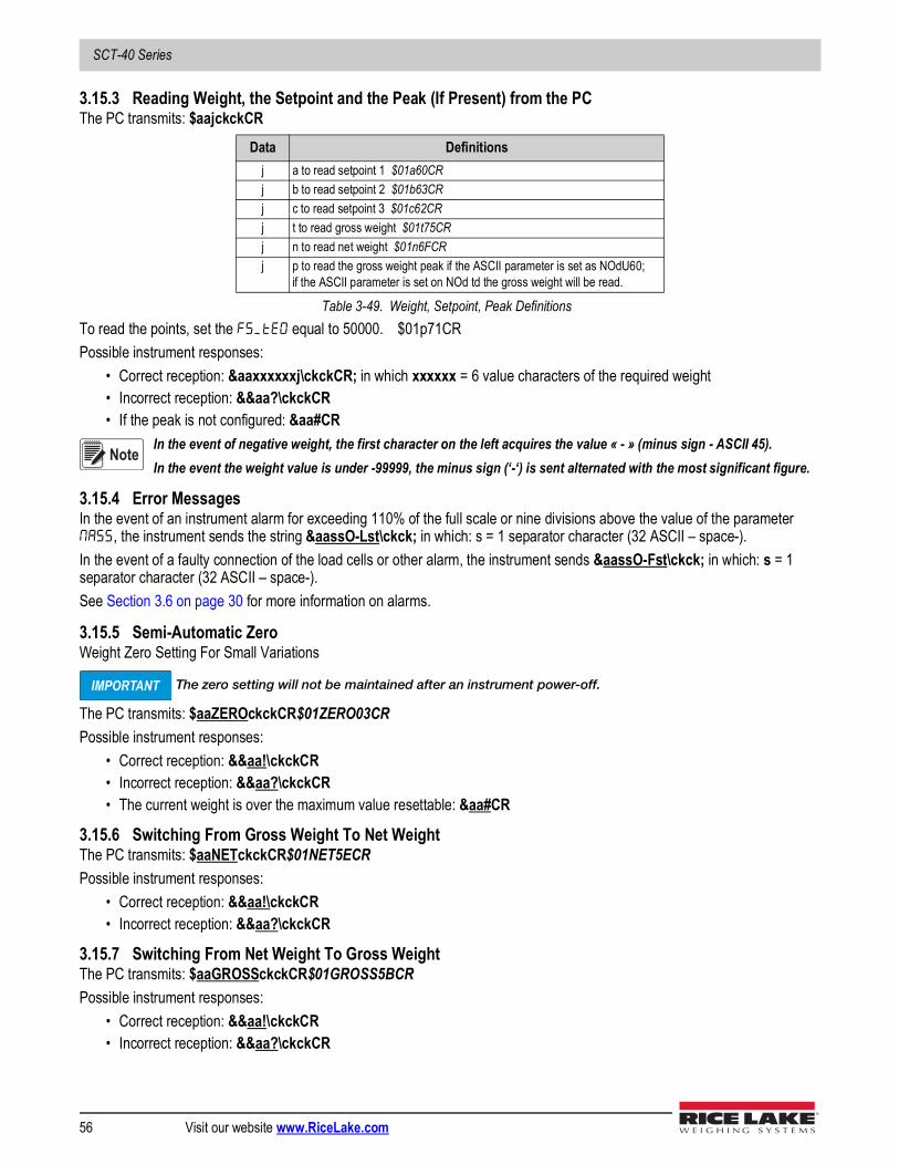
SCT-40 Series
56 Visit our website www.RiceLake.com
3.15.3 Reading Weight, the Setpoint and the Peak (If Present) from the PCThe PC transmits: $aajckckCR
To read the points, set the equal to 50000. $01p71CRPossible instrument responses:
• Correct reception: &aaxxxxxxj\ckckCR; in which xxxxxx = 6 value characters of the required weight • Incorrect reception: &&aa?\ckckCR• If the peak is not configured: &aa#CR
In the event of negative weight, the first character on the left acquires the value « - » (minus sign - ASCII 45).In the event the weight value is under -99999, the minus sign (‘-‘) is sent alternated with the most significant figure.
3.15.4 Error MessagesIn the event of an instrument alarm for exceeding 110% of the full scale or nine divisions above the value of the parameter , the instrument sends the string &aassO-Lst\ckck; in which: s = 1 separator character (32 ASCII – space-).In the event of a faulty connection of the load cells or other alarm, the instrument sends &aassO-Fst\ckck; in which: s = 1 separator character (32 ASCII – space-).See Section 3.6 on page 30 for more information on alarms.
3.15.5 Semi-Automatic Zero Weight Zero Setting For Small Variations
The zero setting will not be maintained after an instrument power-off.
The PC transmits: $aaZEROckckCR$01ZERO03CRPossible instrument responses:
• Correct reception: &&aa!\ckckCR• Incorrect reception: &&aa?\ckckCR• The current weight is over the maximum value resettable: &aa#CR
3.15.6 Switching From Gross Weight To Net WeightThe PC transmits: $aaNETckckCR$01NET5ECRPossible instrument responses:
• Correct reception: &&aa!\ckckCR• Incorrect reception: &&aa?\ckckCR
3.15.7 Switching From Net Weight To Gross WeightThe PC transmits: $aaGROSSckckCR$01GROSS5BCRPossible instrument responses:
• Correct reception: &&aa!\ckckCR• Incorrect reception: &&aa?\ckckCR
Data Definitionsj a to read setpoint 1 $01a60CRj b to read setpoint 2 $01b63CRj c to read setpoint 3 $01c62CRj t to read gross weight $01t75CRj n to read net weight $01n6FCRj p to read the gross weight peak if the ASCII parameter is set as NOdU60;
if the ASCII parameter is set on NOd td the gross weight will be read.
Table 3-49. Weight, Setpoint, Peak Definitions
Note
IMPORTANT

Operation
© Rice Lake Weighing Systems ● All Rights Reserved 57
3.15.8 Reading Of Decimals And Number Of DivisionsThe PC transmits: $aaDckckCR$01D45CRPossible instrument responses:
• Correct reception: &aaxy\ckckCR
• Incorrect reception: &&aa?\ckckCR
3.15.9 Tare Weight Zero SettingThe PC transmit the following ASCII string containing the zeroing command:
• $aazckckCR$01z7BCR; in which: z = weight zeroing command (122 ASCII)Possible instrument responses:
• Correct reception: &aaxxxxxxt\ckckCR
• Incorrect reception: &&aa?\ckckCR• If the instrument is not in gross weight displaying condition, the response is: &aa#CR
Example: Weight zero setting for instrument with address 2:For the calibration, make sure that the scale is empty and the instrument measures a corresponding mV signal.query: $02z78(Cr) response: &02000000t\76(Cr)For a correct weight zero setting the read value (response) must be 0 (in the string 000000).
The zero values are stored to the EEPROM memory. Please note that the number of writes allowed is limited (about 100000). If it is necessary to reset the weight quite often, it is recommended to perform it by PC or PLC program, keeping in mind the weight deviation respect to the zero instrument.
Response Value Definitionx number of decimalsy division value
The y field acquires the following values3 for division value = 14 for division value = 25 for division value = 56 for division value = 107 for division value = 208 for division value = 509 for division value = 100
Table 3-50. Decimal and Division Definitions
Data Definitionxxxxxx 6 characters for the required weight value.
t weight identification code (116 ASCII).
Table 3-51. Zeroing Command String Definition
IMPORTANT
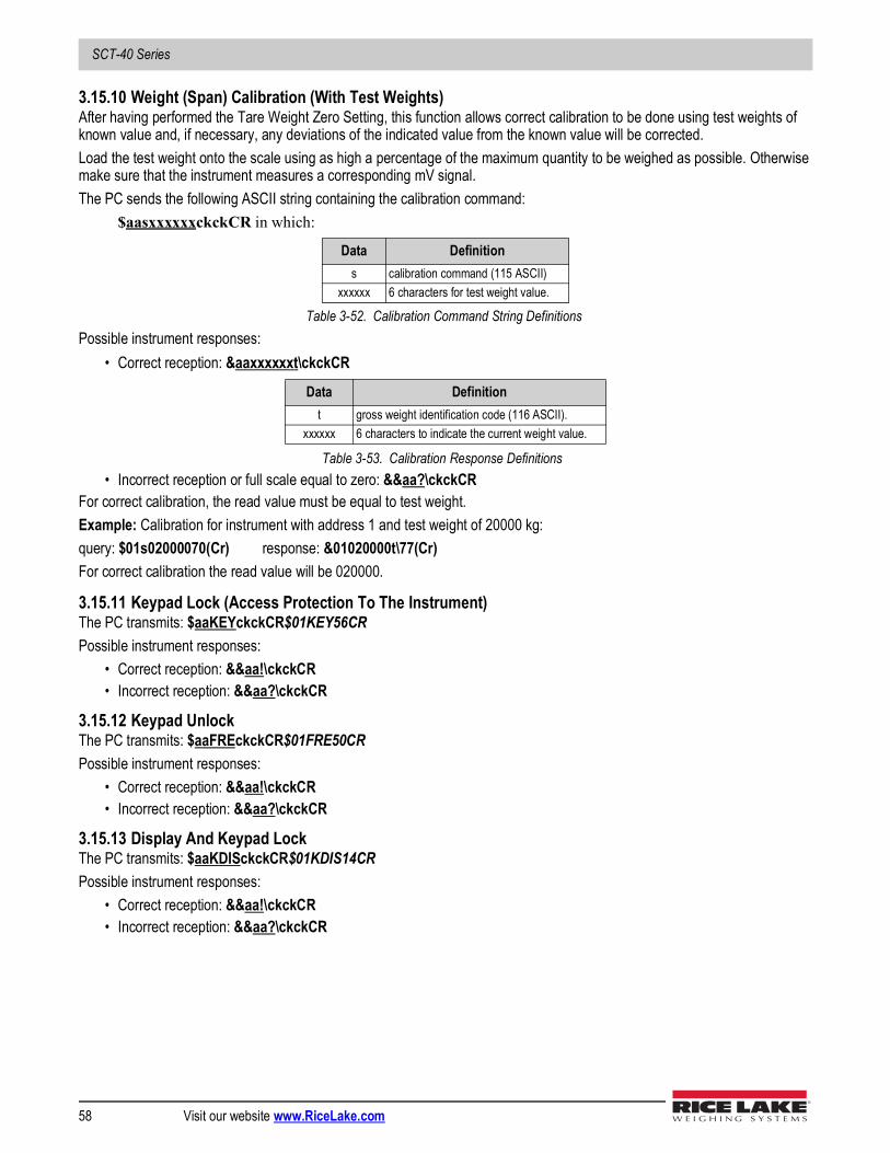
SCT-40 Series
58 Visit our website www.RiceLake.com
3.15.10 Weight (Span) Calibration (With Test Weights)After having performed the Tare Weight Zero Setting, this function allows correct calibration to be done using test weights of known value and, if necessary, any deviations of the indicated value from the known value will be corrected.Load the test weight onto the scale using as high a percentage of the maximum quantity to be weighed as possible. Otherwise make sure that the instrument measures a corresponding mV signal.The PC sends the following ASCII string containing the calibration command:
$aasxxxxxxckckCR in which:
Possible instrument responses:• Correct reception: &aaxxxxxxt\ckckCR
• Incorrect reception or full scale equal to zero: &&aa?\ckckCR For correct calibration, the read value must be equal to test weight.Example: Calibration for instrument with address 1 and test weight of 20000 kg:query: $01s02000070(Cr) response: &01020000t\77(Cr)For correct calibration the read value will be 020000.
3.15.11 Keypad Lock (Access Protection To The Instrument)The PC transmits: $aaKEYckckCR$01KEY56CRPossible instrument responses:
• Correct reception: &&aa!\ckckCR• Incorrect reception: &&aa?\ckckCR
3.15.12 Keypad UnlockThe PC transmits: $aaFREckckCR$01FRE50CRPossible instrument responses:
• Correct reception: &&aa!\ckckCR• Incorrect reception: &&aa?\ckckCR
3.15.13 Display And Keypad LockThe PC transmits: $aaKDISckckCR$01KDIS14CRPossible instrument responses:
• Correct reception: &&aa!\ckckCR• Incorrect reception: &&aa?\ckckCR
Data Definitions calibration command (115 ASCII)
xxxxxx 6 characters for test weight value.
Table 3-52. Calibration Command String Definitions
Data Definitiont gross weight identification code (116 ASCII).
xxxxxx 6 characters to indicate the current weight value.
Table 3-53. Calibration Response Definitions
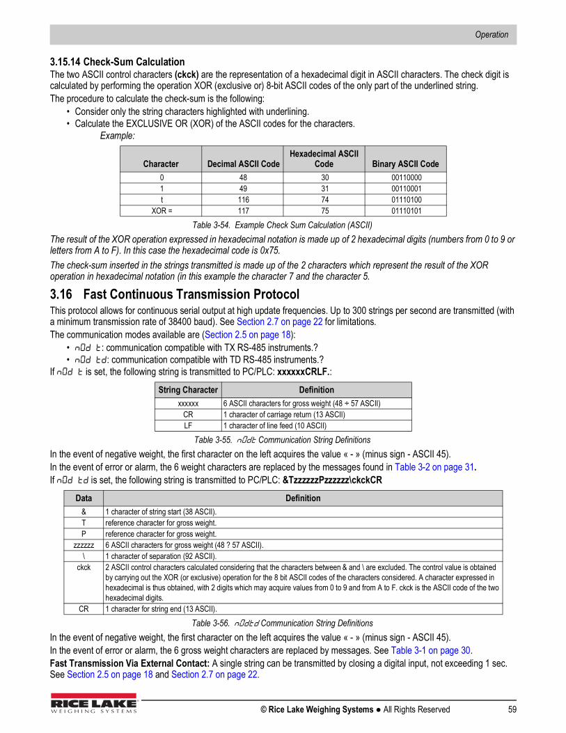
Operation
© Rice Lake Weighing Systems ● All Rights Reserved 59
3.15.14 Check-Sum CalculationThe two ASCII control characters (ckck) are the representation of a hexadecimal digit in ASCII characters. The check digit is calculated by performing the operation XOR (exclusive or) 8-bit ASCII codes of the only part of the underlined string.The procedure to calculate the check-sum is the following:
• Consider only the string characters highlighted with underlining.• Calculate the EXCLUSIVE OR (XOR) of the ASCII codes for the characters.
Example:
The result of the XOR operation expressed in hexadecimal notation is made up of 2 hexadecimal digits (numbers from 0 to 9 or letters from A to F). In this case the hexadecimal code is 0x75.The check-sum inserted in the strings transmitted is made up of the 2 characters which represent the result of the XOR operation in hexadecimal notation (in this example the character 7 and the character 5.
3.16 Fast Continuous Transmission ProtocolThis protocol allows for continuous serial output at high update frequencies. Up to 300 strings per second are transmitted (with a minimum transmission rate of 38400 baud). See Section 2.7 on page 22 for limitations.The communication modes available are (Section 2.5 on page 18):
• : communication compatible with TX RS-485 instruments.?• : communication compatible with TD RS-485 instruments.?
If is set, the following string is transmitted to PC/PLC: xxxxxxCRLF.:
In the event of negative weight, the first character on the left acquires the value « - » (minus sign - ASCII 45).In the event of error or alarm, the 6 weight characters are replaced by the messages found in Table 3-2 on page 31.If is set, the following string is transmitted to PC/PLC: &TzzzzzzPzzzzzz\ckckCR
In the event of negative weight, the first character on the left acquires the value « - » (minus sign - ASCII 45).In the event of error or alarm, the 6 gross weight characters are replaced by messages. See Table 3-1 on page 30.Fast Transmission Via External Contact: A single string can be transmitted by closing a digital input, not exceeding 1 sec. See Section 2.5 on page 18 and Section 2.7 on page 22.
Character Decimal ASCII CodeHexadecimal ASCII
Code Binary ASCII Code 0 48 30 00110000 1 49 31 00110001 t 116 74 01110100
XOR = 117 75 01110101
Table 3-54. Example Check Sum Calculation (ASCII)
String Character Definitionxxxxxx 6 ASCII characters for gross weight (48 ÷ 57 ASCII)
CR 1 character of carriage return (13 ASCII)LF 1 character of line feed (10 ASCII)
Table 3-55. Communication String Definitions
Data Definition& 1 character of string start (38 ASCII).T reference character for gross weight.P reference character for gross weight.
zzzzzz 6 ASCII characters for gross weight (48 ? 57 ASCII).\ 1 character of separation (92 ASCII).
ckck 2 ASCII control characters calculated considering that the characters between & and \ are excluded. The control value is obtained by carrying out the XOR (or exclusive) operation for the 8 bit ASCII codes of the characters considered. A character expressed in hexadecimal is thus obtained, with 2 digits which may acquire values from 0 to 9 and from A to F. ckck is the ASCII code of the two hexadecimal digits.
CR 1 character for string end (13 ASCII).
Table 3-56. Communication String Definitions

SCT-40 Series
60 Visit our website www.RiceLake.com
3.17 Continuous Transmission ProtocolUsing this protocol, the instrument transmits, in continuous mode, the weight to remote displays; the communication string is transmitted 10 times per second. The communication modes available are (Section 2.5 on page 18):
• : remote display shows the net or gross weight, depending on the remote display setting.• : remote display shows the net or gross weight, depending on the remote display setting.• :
The instrument sends the following string to the remote display: • &NxxxxxxLyyyyyy\ckckCR
In the event of negative weight, the first character on the left acquires the value « - » (minus sign - ASCII 45).If the protocol on has been set, the decimal point at the position shown on the instrument's display can also be transmitted. In this case, if the value exceeds five digits, only the five most significant digits are transmitted, while if the value is negative, no more than the 4 most significant digits are transmitted. In both cases, however, the decimal point shifts consistently with the value to display.If has been set, in addition to what is stated in protocol, the instrument transmits the prompt net every four seconds in the gross weight field, when the instrument is in net mode. See Section 3.2 on page 29.In case weight value is under -99999, the minus sign (-) is sent alternated with the most significant figure.In the event of an error or alarm, the six characters of the gross and net weight are replaced by the messages found in Table 3-1 on page 30.
3.18 Interface to Remote DisplayRemote Display (Laser Light)
1. Press and hold , then press . is displayed.2. Press or until is displayed. 3. Press . is displayed.4. Press . is displayed.5. Press or until is displayed. Press .6. Press twice to exit set-up menu.
Data Definition& 1 character of string start (38 ASCII)N 1 reference character for net weight. (78 ASCII)
xxxxxx 6 ASCII characters for net or peak weight if present (48 ÷ 57 ASCII)L 1 reference character for gross weight (76 ASCII)
yyyyyy 6 ASCII characters for gross weight (48 ? 57 ASCII).\ 1 character for separation (92 ASCII)
ckck 2 ASCII control characters calculated considering that the characters between & and \ are excludedThe control value is obtained by carrying out the XOR (or exclusive) operation for the 8 bit ASCII codes of the characters considered. character expressed in hexadecimal is thus obtained, with 2 digits which may acquire values from 0 to 9 and from A to F. ckck is the ASCII code of the two hexadecimal digits.
CR character for string end (13 ASCII).
Table 3-57. Continuous Transmission Protocol Data Definitions
Laser Light SCTE CHAR = CRLWPOS = 7LENGTH = 19
Connector Pin ConnectorJ8 (RS-232) \3 RS-485 RX-
5 RS-485 RX+
Table 3-58. Laser Light Setup

Operation
© Rice Lake Weighing Systems ● All Rights Reserved 61
3.19 Communication ExamplesThe numerical data below is expressed in hexadecimal notation with the prefix h.
Example 1: Command for multiple writing of registers (hexadecimal command 16, h10)Assuming that we wish to write the value 0 to the register 40017 and the value 2000 to the register 40018, the string to generate must be:h01 h10 h00 h10 h00 h02 h04 h00 h00 h07 hD0 hF1 h0FThe instrument will respond with the string:h01 h10 h00 h10 h00 h02 h40 h0D
Example 2: Command for multiple writing of registers (hexadecimal command 16, h10).Assuming that we wish to write the two setpoint values on the instrument, at 2000 and 3000 respectively, the string must be sent:h01 h10 h00 h10 h00 h04 h08 h00 h00 h07 hD0 h00 h00 h0B hB8hB0 hA2
Query Field Name Hex Response Field Name HexInstrument Address h01 Instrument Address h01 Function h10 Function h10 Address of the first register H h00 Address of the first register H h00 Address of the first register L h10 Address of the first register L h10 Number of registers to send H h00 Number of registers H h00 Number of registers to send L h02 Number of registers L h02 Byte Count h04 CRC16 H h40 Datum 1 H h00 CRC16 L h0D Datum 1 L h00 Datum 2 H h07Datum 2 L hD0CRC16 H hF1CRC16 L h0F
Table 3-59. Communication Example 1
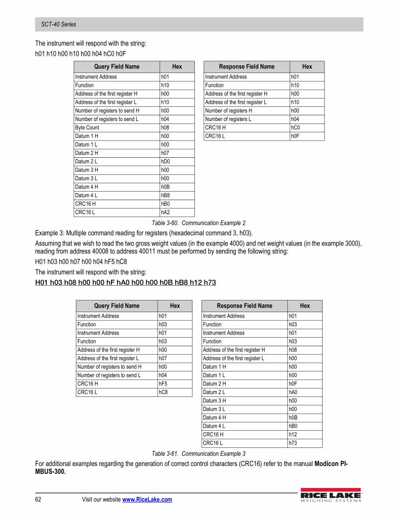
SCT-40 Series
62 Visit our website www.RiceLake.com
The instrument will respond with the string:h01 h10 h00 h10 h00 h04 hC0 h0F
Example 3: Multiple command reading for registers (hexadecimal command 3, h03).Assuming that we wish to read the two gross weight values (in the example 4000) and net weight values (in the example 3000), reading from address 40008 to address 40011 must be performed by sending the following string:H01 h03 h00 h07 h00 h04 hF5 hC8The instrument will respond with the string:H01 h03 h08 h00 h00 hF hA0 h00 h00 h0B hB8 h12 h73
For additional examples regarding the generation of correct control characters (CRC16) refer to the manual Modicon PI-MBUS-300.
Query Field Name Hex Response Field Name HexInstrument Address h01 Instrument Address h01 Function h10 Function h10 Address of the first register H h00 Address of the first register H h00 Address of the first register L h10 Address of the first register L h10 Number of registers to send H h00 Number of registers H h00 Number of registers to send L h04 Number of registers L h04 Byte Count h08 CRC16 H hC0 Datum 1 H h00 CRC16 L h0FDatum 1 L h00 Datum 2 H h07Datum 2 L hD0Datum 3 H h00 Datum 3 L h00 Datum 4 H h0BDatum 4 L hB8CRC16 H hB0CRC16 L hA2
Table 3-60. Communication Example 2
Query Field Name Hex Response Field Name HexInstrument Address h01 Instrument Address h01 Function h03 Function h03 Instrument Address h01 Instrument Address h01 Function h03 Function h03 Address of the first register H h00 Address of the first register H h08Address of the first register L h07 Address of the first register L h00 Number of registers to send H h00 Datum 1 H h00 Number of registers to send L h04 Datum 1 L h00 CRC16 H hF5 Datum 2 H h0FCRC16 L hC8 Datum 2 L hA0
Datum 3 H h00 Datum 3 L h00 Datum 4 H h0BDatum 4 L hB0CRC16 H h12CRC16 L h73
Table 3-61. Communication Example 3
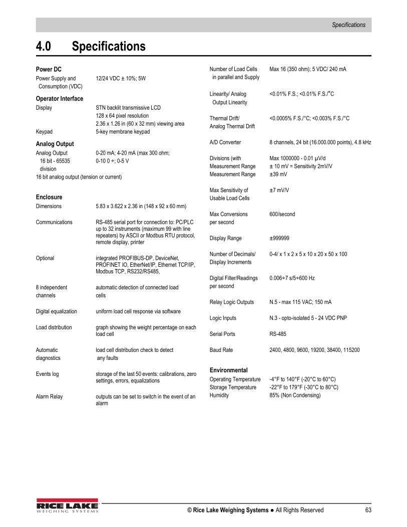
Specifications
© Rice Lake Weighing Systems ● All Rights Reserved 63
4.0 SpecificationsPower DCPower Supply and 12/24 VDC ± 10%; 5W Consumption (VDC)
Operator InterfaceDisplay STN backlit transmissive LCD
128 x 64 pixel resolution2.36 x 1.26 in (60 x 32 mm) viewing area
Keypad 5-key membrane keypad
Analog OutputAnalog Output 0-20 mA; 4-20 mA (max 300 ohm; 16 bit - 65535 0-10 0 ÷; 0-5 V division16 bit analog output (tension or current)
EnclosureDimensions 5.83 x 3.622 x 2.36 in (148 x 92 x 60 mm)
Communications RS-485 serial port for connection to: PC/PLC up to 32 instruments (maximum 99 with line repeaters) by ASCII or Modbus RTU protocol, remote display, printer
Optional integrated PROFIBUS-DP, DeviceNet, PROFINET IO, EtherNet/IP, Ethernet TCP/IP, Modbus TCP, RS232/RS485,
8 independent automatic detection of connected load channels cells
Digital equalization uniform load cell response via software
Load distribution graph showing the weight percentage on each load cell
Automatic load cell distribution check to detectdiagnostics any faults
Events log storage of the last 50 events: calibrations, zero settings, errors, equalizations
Alarm Relay outputs can be set to switch in the event of an alarm
Number of Load Cells Max 16 (350 ohm); 5 VDC/ 240 mA in parallel and Supply
Linearity/ Analog <0.01% F.S.; <0.01% F.S./°C Output Linearity
Thermal Drift/ <0.0005% F.S./°C; <0.003% F.S./°CAnalog Thermal Drift
A/D Converter 8 channels, 24 bit (16.000.000 points), 4.8 kHz
Divisions (with Max 1000000 - 0.01 µV/dMeasurement Range ± 10 mV = Sensitivity 2mV/VMeasurement Range ±39 mV
Max Sensitivity of ±7 mV/VUsable Load Cells
Max Conversions 600/secondper second
Display Range ±999999
Number of Decimals/ 0-4/ x 1 x 2 x 5 x 10 x 20 x 50 x 100Display Increments
Digital Filter/Readings 0.006÷7 s/5÷600 Hzper second
Relay Logic Outputs N.5 - max 115 VAC; 150 mA
Logic Inputs N.3 - opto-isolated 5 - 24 VDC PNP
Serial Ports RS-485
Baud Rate 2400, 4800, 9600, 19200, 38400, 115200
EnvironmentalOperating Temperature -4°F to 140°F (-20°C to 60°C)Storage Temperature -22°F to 179°F (-30°C to 80°C)Humidity 85% (Non Condensing)


230 W. Coleman St. • Rice Lake, WI 54868 • USAU.S. 800-472-6703 • Canada/Mexico 800-321-6703 • International 715-234-9171 • Europe +31 (0)26 472 1319
Rice Lake Weighing Systems is an ISO 9001 registered company. © Rice Lake Weighing Systems Specifications subject to change without notice.
www.ricelake.comFebruary 26, 2020 PN 171954 Rev D