Embed Size (px)
Citation preview

SCT Weight Transmitter10 Series
Installation & Operator’s Manual
131129 Rev C

Contents i
Contents1.0 Introduction.................................................................................. 1
1.1 Safety . . . . . . . . . . . . . . . . . . . . . . . . . . . . . . . . . . . . . . . . . . . . . . . . 11.1.1 Equipment Recommendations . . . . . . . . . . . . . . . . . . . . . . . . . . . . . . . . . 21.1.2 Correct Installation Of Weighing Instruments . . . . . . . . . . . . . . . . . . . . . . 21.1.3 Correct Installation Of The Load Cells . . . . . . . . . . . . . . . . . . . . . . . . . . . 2
1.2 Load Cells. . . . . . . . . . . . . . . . . . . . . . . . . . . . . . . . . . . . . . . . . . . . . 31.2.1 Load Cell Input Test (Quick Access) . . . . . . . . . . . . . . . . . . . . . . . . . . . . . 31.2.2 Load Cell Testing . . . . . . . . . . . . . . . . . . . . . . . . . . . . . . . . . . . . . . . . . . . 4
1.3 Specifications . . . . . . . . . . . . . . . . . . . . . . . . . . . . . . . . . . . . . . . . . 41.4 Electrical Connections . . . . . . . . . . . . . . . . . . . . . . . . . . . . . . . . . . . 51.5 LED and Key Functions . . . . . . . . . . . . . . . . . . . . . . . . . . . . . . . . . 61.6 Instrument Commissioning . . . . . . . . . . . . . . . . . . . . . . . . . . . . . . . 7
1.6.1 If The Instrument Has Not Been Calibrated . . . . . . . . . . . . . . . . . . . . . . . 7
2.0 Configuration ............................................................................... 82.1 Calibration . . . . . . . . . . . . . . . . . . . . . . . . . . . . . . . . . . . . . . . . . . . 10
2.1.1 Theoretical Calibration . . . . . . . . . . . . . . . . . . . . . . . . . . . . . . . . . . . . . . 132.1.2 Maximum Capacity (NASS ) . . . . . . . . . . . . . . . . . . . . . . . . . . . . . . . . . . 132.1.3 Zero Setting . . . . . . . . . . . . . . . . . . . . . . . . . . . . . . . . . . . . . . . . . . . . . . 142.1.4 Zero Value Manual Entry . . . . . . . . . . . . . . . . . . . . . . . . . . . . . . . . . . . . 142.1.5 Weight (Span) Calibration (With Test Weights) . . . . . . . . . . . . . . . . . . . . 152.1.6 Setting Units of Measure . . . . . . . . . . . . . . . . . . . . . . . . . . . . . . . . . . . . 162.1.7 Display Coefficient . . . . . . . . . . . . . . . . . . . . . . . . . . . . . . . . . . . . . . . . . 16
2.2 Filter On The Weight . . . . . . . . . . . . . . . . . . . . . . . . . . . . . . . . . . . 172.3 Zero Parameters. . . . . . . . . . . . . . . . . . . . . . . . . . . . . . . . . . . . . . . 192.4 Analog Output . . . . . . . . . . . . . . . . . . . . . . . . . . . . . . . . . . . . . . . . 20
2.4.1 Soldered Jumper . . . . . . . . . . . . . . . . . . . . . . . . . . . . . . . . . . . . . . . . . . 212.4.2 Analog Output Type Scale Corrections . . . . . . . . . . . . . . . . . . . . . . . . . 21
2.5 Serial Communication Settings . . . . . . . . . . . . . . . . . . . . . . . . . . . 222.5.1 RS-485 Serial Communication . . . . . . . . . . . . . . . . . . . . . . . . . . . . . . . . 24
2.6 Outputs And Inputs Configuration . . . . . . . . . . . . . . . . . . . . . . . . 252.7 Test . . . . . . . . . . . . . . . . . . . . . . . . . . . . . . . . . . . . . . . . . . . . . . . . . 272.8 Setpoints Programming. . . . . . . . . . . . . . . . . . . . . . . . . . . . . . . . . 282.9 Reserved For The Installer. . . . . . . . . . . . . . . . . . . . . . . . . . . . . . . 29
2.9.1 Default Scale . . . . . . . . . . . . . . . . . . . . . . . . . . . . . . . . . . . . . . . . . . . . . 292.9.2 Program Selection - Reverse: . . . . . . . . . . . . . . . . . . . . . . . . . . . . . . . . 292.9.3 Keypad Or Display Locking . . . . . . . . . . . . . . . . . . . . . . . . . . . . . . . . . . 30
© Rice Lake Weighing Systems. All rights reserved. Printed in the United States of America. Specifications subject to change without notice.
Rice Lake Weighing Systems is an ISO 9001 registered company.October 20, 2017
Technical training seminars are available through Rice Lake Weighing Systems.
Course descriptions and dates can be viewed at www.ricelake.com/trainingor obtained by calling 715-234-9171 and asking for the training department.

ii SCT Weight Transmitter Operator’s Manual
Rice Lake continually offers web-based video training on a growing selection
of product-related topics at no cost. Visit www.ricelake.com/webinars.
3.0 Operation.................................................................................... 313.1 Semi-Automatic Tare (Net/Gross) . . . . . . . . . . . . . . . . . . . . . . . . . 313.2 Preset Tare (Subtractive Tare Device) . . . . . . . . . . . . . . . . . . . . . 313.3 Semi-Automatic Zero (Weight Zero-setting For Small Variations). .
323.4 Peak . . . . . . . . . . . . . . . . . . . . . . . . . . . . . . . . . . . . . . . . . . . . . . . . 323.5 Alarms. . . . . . . . . . . . . . . . . . . . . . . . . . . . . . . . . . . . . . . . . . . . . . . 323.6 Modbus-RTU Protocol. . . . . . . . . . . . . . . . . . . . . . . . . . . . . . . . . . 333.7 ASCII Bidirectional Protocol . . . . . . . . . . . . . . . . . . . . . . . . . . . . . 403.8 Fast Continuous Transmission Protocol. . . . . . . . . . . . . . . . . . . . 453.9 Continuous Transmission Protocol To Remote Displays. . . . . . . 463.10 Interface to Remote Display . . . . . . . . . . . . . . . . . . . . . . . . . . . . 473.11 Communication Examples. . . . . . . . . . . . . . . . . . . . . . . . . . . . . . 48
4.0 Specifications ............................................................................ 51

Introduction 1
1.0 IntroductionManuals and Firmware/Software are available for viewing and/or downloading from the Rice Lake Weighing Systems website at www.ricelake.com/manuals
Warranty information can be found on the website at www.ricelake.com/warranties
1.1 SafetySafety Signal Definitions:
Indicates an imminently hazardous situation that, if not avoided, will result in death or serious injury. Includes hazards that are exposed when guards are removed.
Indicates a potentially hazardous situation that, if not avoided could result in serious injury or death. Includes hazards that are exposed when guards are removed.
Indicates a potentially hazardous situation that, if not avoided, could result in minor or moderate injury.
Indicates information about procedures that, if not observed, could result in damage to equipment or corruption to and loss of data.
General Safety
Do not operate or work on this equipment unless this manual has been read and all instructions are understood. Failure to follow the instructions or heed the warnings could result in injury or death. Contact any Rice Lake Weighing Systems dealer for replacement manuals.
Failure to heed could result in serious injury or death.
Risk of electrical shock. No user serviceable parts. Refer to qualified servicepersonnel for service.
The unit has no power switch, to completely remove D/C power from the unit,disconnect the D/C power cable from the main socket.
Do not allow minors (children) or inexperienced persons to operate this unit.
Do not operate without all shields and guards in place.
Do not use for purposes other then weighing applications.
Do not place fingers into slots or possible pinch points.
Do not use this product if any of the components are cracked.
Do not make alterations or modifications to the unit.
Do not remove or obscure warning labels.
Do not submerge.
DANGER
WARNING
CAUTION
IMPORTANT
WARNING

2 SCT Weight Transmitter Operator’s Manual
1.1.1 Equipment RecommendationsFailure to follow the installation recommendations will beconsidered a misuse of the equipment
To Avoid Equipment Damage• Keep away from heat sources and direct sunlight.• Protect the instrument from rain.• Do not wash, dip in water or spill liquid on the instrument.• Do not use solvents to clean the instrument.• Do not install in areas subject to explosion hazard.
1.1.2 Correct Installation Of Weighing Instruments• The terminals indicated on the instrument’s wiring diagram to be connected to
earth must have the same potential as the scale structure (ground). If unable toensure this condition, connect a ground wire between the instrument and thescale structure.
• The load cell cable must be run separately to the instrument input and not share aconduit with other cables. A shielded connection must be continuous without asplice.
• Use “RC” filters (quench-arcs) on the instrument-driven solenoid valve andremote control switch coils.
• Avoid electrical noise in the instrument panel; if inevitable, use special filters orsheet metal partitions to isolate.
• The panel installer must provide electrical protection for the instruments (fuses,door lock switch, etc.).
• It is advisable to leave equipment always switched on to prevent the formation ofcondensation.
• Maximum Cable Lengths:- RS-485: 1000 meters with AWG24, shielded and twisted cables- RS-232: 15 meters for baud rates up to 19200
1.1.3 Correct Installation Of The Load CellsInstalling Load Cells: The load cells must be placed on rigid, stable structures within .5% of plumb andlevel. It is important to use mounting modules for load cells to compensate formisalignment of the support surfaces.
Protection Of The Load Cell Cable: Use water-proof sheaths and joints in order to protect the cables of the load cells.
Mechanical Restraints (pipes, etc.): When pipes are present, we recommend the use of hoses, flexible couplings andrubber skirted joints. In case of rigid conduit and pipes, place the pipe support oranchor bracket as far as possible from the weighed structure (at a distance at least 40times the diameter of the pipe).
Welding: Avoid welding with the load cells already installed. If this cannot be avoided, placethe welder ground clamp close to the required welding point to prevent sendingcurrent through the load cell body.
IMPORTANT
Introduction 3
Windy Conditions - Shocks - Vibrations: The use of weigh modules is strongly recommended for all load cells to compensatefor misalignment of the support surfaces. The system designer must ensure that thescale is protected against lateral shifting and tipping relating to shocks and vibration,windy conditions, seismic conditions and stability of the support structure.
Grounding The Weighed Structure: By means of a 10ga solid or braided wire or braided grounding strap, connect the loadcell upper support plate with the lower support plate, then connect all the lower platesto a single earth ground. Once installed electrostatic charges accumulated aredischarged to the ground without going through or damaging the load cells. Failure toimplement a proper grounding system might not affect the operation of the weighingsystem; this, however, does not rule out the possibility that the load cells andconnected instrument may become damaged by ESD. It is forbidden to ensuregrounding system continuity by using metal parts contained in the weighedstructure.(see Figure 1-1.)
Figure 1-1. Installation Recommendations
1.2 Load Cells1.2.1 Load Cell Input Test (Quick Access)
1. From the weight display, press for 3 seconds.
2. The display will read NU-CEL. Press .
3. The response signal of the load cell is displayed, expressed in mV with four
decimals. Press three times to exit set-up mode.
Uses ground plate to continue ground.
Uses structure to continue ground.
MENU
0ESC
4 SCT Weight Transmitter Operator’s Manual
1.2.2 Load Cell TestingLoad Cell Resistance Measurement (Use A Digital Multimeter):
• Disconnect the load cells from the instrument and check that there is no moisturein the load cell junction box caused by condensation or water infiltration. If so,drain the system or replace it if necessary.
• The value between the positive signal wire and the negative signal wire must beequal or similar to the one indicated in the load cell data sheet (output resistance).
• The value between the positive excitation wire and the negative excitation wiremust be equal or similar to the one indicated in the load cell data sheet (inputresistance).
• The insulation value between the shield and any other load cell wire and betweenany other load cell wire and the body of the load cell must be higher than 20Mohm (mega ohms).
Load Cell Voltage Measurement (Use A Digital Multimeter):• Remove weight of scale from load cell to be tested.• Make sure that the excitation wires of the load cell connected to the instrument is
5 Vdc +/- 3%.• Measure the millivolt signal between the positive and the negative signal wires
by directly connecting them to the multi-meter, and make sure it reads between 0and 0.5 mV (thousandths of a Volt).
• Apply load to the load cell and make sure that there is a signal increment.If one of the above conditions is not met, please contact thetechnical assistance service.
1.3 Specifications
• Weight indicator and transmitter for Omega/DIN rail mounting suitable for backpanel; space saving vertical shape. Six-digit semi alphanumeric display (18mmh), 7 segment. Four-key keyboard. Dimensions: 25x115x120 mm.
• Displays the gross weight; with an external contact capable of remote zeroingand gross/net switching.
• IP67 box version (dimensions: 170x140x95mm). Four fixing holes diameter4mm (center distance 122x152mm).
• Peak weight function.
IMPORTANT
ANALOG OUTPUT (Current and Voltage)
PLC
PLC or FIELD SIGNALS 2 DIGITAL INPUTS
(Optoisolated, Externally supplied)
2 RELAY OUTPUTS
MAX 8 LOAD CELLS IN PARALLEL
RS-485RS-232Modbus RTU
SERIAL PORT
DC power supplier
(12-24 Volt )
Introduction 5
• Transmits the gross or net weight via opto-isolated analog output 16 bit, current0-20mA, 4-20mA or voltage 0-10V, 0-5V (±0V / ±5V by closing a solderedjumper).
• Transmits the gross or net weight via RS-485 serial port, by means of protocols:- Modbus RTU- ASCII bidirectional protocol- Continuous transmission
1.4 Electrical Connections• It is recommended that the negative side of the power supply be grounded.• It is possible to power up to eight 350 ohm load cells or sixteen 700 ohm load
cells.• Connect terminal “0 VDC” to the RS-485 common of the connected instruments
in the event that these receive alternating current input or that they have an opto-isolated RS-485.
• In case of an RS-485 network with several devices it is recommended to activatethe 120 ohm termination resistance on the two devices located at the ends of thenetwork, see Section 2.5.1 on page 24.
2 outputs: configurable setpoints or remote output management via protocol.2 inputs (Default: SEMI-AUTOMATIC ZERO input 1; NET/GROSS input 2):settable to have the following functions: SEMI-AUTOMATIC ZERO, NET/GROSS, PEAK, or REMOTE CONTROL (see Section 2.6 on page 25).
131 2 3 4 5 6 7 8 9 111210 21141516171819 20
SH
LOAD CELLS IN PARALLEL
IN1
IN2
IN C
OM
OU
T1O
UT2
+ R
S48
5- R
S48
5m
A Vm
A-V
CO
M
NET 0 kg g L
INPUTS5-24Vdc
OUTPUTS 24Vdc 60mA
RS485
OUTPUT
12-24Vdc
ANALOG
RS485 termination
0
ESC
333130 322827252324 26 2922 34
+ 12
-24
0 V
DC
POWER
+ E
X- E
X
- SIG
+ S
IG
- EX
+ E
X- S
IG+
SIG
SH - E
X+
EX
- SIG
+ S
IGS
H - EX
+ E
X- S
IG+
SIG
SH
J1 J2
SCT
Current output: max load 300 OhmVoltage output: min. load 10 kOhm
- EXC
ITAT
ION
+ EXC
ITAT
ION
- SIG
NAL
+ SIG
NAL
- EXC
ITAT
ION
+ EXC
ITAT
ION
- SIG
NAL
+ SIG
NAL
- EXC
ITAT
ION
+ EXC
ITAT
ION
- SIG
NAL
+ SIG
NAL
- EXC
ITAT
ION
+ EXC
ITAT
ION
- SIG
NAL
+ SIG
NAL

6 SCT Weight Transmitter Operator’s Manual
1.5 LED and Key Functions
* To activate the secondary LED function, during weight display press and hold
, then press .
The LEDs light up in sequence to indicate that a setting and not a weightis being viewed.
LED Main function Secondary function *
NET Net weight LED: net weight display (semi-automatic tare or preset tare)
LED lit: input 1 cosed
Zero LED (deviation from zero not more than+/- 0.25 divisions)
LED lit: input 2 closed
Stability LED LED lit: output 1 closedkg Unit of measure: kg LED lit: output 2 closedg Unit of measure: g No meaningL Unit of measure:lb No meaning
Key Short pressLong press
(3 sec) Into menus
Escape
Zero Setting Cancel or return to previous menu
Scroll/ Backspace
Captures TareGross Net
Removes TareNet Gross
Select figure to be modified or return to previous menu item
Next/ Data Entry
mV load cell test
Modify selected figure or go to next menu item
Enter
Setting setpoints and hysteresis
Confirm or enter in submenu
+ Setting general parameters (press and hold then press to
enter set-up menu.
+ Setting preset tare (press and hold then press to enter
set-up menu.
0
MENU PRINT
0ESC
TARE
MENU
MENU0
ESC MENU0
ESC
MENU TARE MENU TARE
Note

Introduction 7
1.6 Instrument Commissioning1. Plug power cord in to outlet to turn on indicator, the display shows in
sequence:- “SU” followed by the software code (e.g.: SU S );- - “r” followed by the software version (e.g.: r 1.04.01 );- - “HU” followed by the hardware code (e.g.: HU 104 );- - the serial number (e.g.:1005 15 );
2. Check that the display shows the weight and that when loading the load cellsthere is an increase in weight.
3. If there is not, check and verify the connections and correct positioning ofthe load cells.
If instrument has NOT been calibrated complete Section 2.1 beforeproceeding to next step.
4. Reset to zero. See Section 2.1.3 on page 14.5. Check the calibration with test weights and correct the indicated weight if
necessary. See Section 2.1.5 on page 15.6. To use the analog output, set the desired analog output type and the full scale
value. See Section 2.4 on page 20.7. To use serial communication, set the related parameters. See Section 2.5 on
page 22.8. If setpoints are used, set the required weight values and the relevant
parameters. See Section 2.8 on page 28 and Section 2.6 on page 25.
1.6.1 If The Instrument Has Not Been Calibrated Missing plant system identification tag, proceed with calibration:
1. If load cells data are unknown, follow the procedure in Section 2.1.5 onpage 15.
2. Enter the rated data of load cells following the procedure given in Section2.1.1 on page 13.
Note

8 SCT Weight Transmitter Operator’s Manual
2.0 Configuration
Figure 2-1. Scale Menu Structure
CALIB FILTER PARA 0
SERIAL
0 SETAUTO 0TRAC 0
TESTOut-In
2345
10
89
76
SeeSerial
Submenu
SeeCalib
Submenu
SeeSerial
Submenu
INOUT
NU CEL
Enter #
ANALOG
MODETYPE
Enter #
0-10 V0-20 mA4-20mA
ANA 0 ANA FS COR FSCOR 0
Enter # Enter # Enter #Enter #
-5+5 V-10+10 V
0-5 V
GrossNet
000000 PtArESEtP1

Configuration 9
Parameter Choices Description
See Section 2.1Section 2.1 on page 10.
Allows a stable weight display to be obtained.See Section 2.2 on page 17.
See Section 2.3 on page 19.
See Section 2.4 on page 20.
See Section 2.5 on page 22.
See Section 2.6 on page 25.
See Section 2.7 on page 27.
* - indicates default value.
Table 2-1. Scale Menu

10 SCT Weight Transmitter Operator’s Manual
2.1 Calibration
Figure 2-2. Calibration Menu Structure
Parameter Choices Description
Enter #deno *
System Full Scale is determined by multiplying one load cell capacity by the number of load cells used.Example of system full scale value calculation:
4 cells of 1000kg ----> FULL SCALE = 1000 X 4 = 4000
NOTE: The instrument is supplied with atheoretical full scale value deno corresponding to10000. To restore factory values, set 0 as fullscale.
Enter #0.50000to7.00000
2.00000 *
Sensitivity is a load cell rated parameter expressed in mV/V. Set the average sensitivity value indicated on the load cells. IExample of 4-cell system with sensitivity
2.00100, 2.00150, 2.00200, 2.00250; enter 2.00175,
calculated as (2.00100 + 2.00150 + 2.00200 + 2.00250) / 4.
Table 2-2. Calibration Menu
Enter # Enter # Enter # Enter # Enter #Enter #

Configuration 11
12 *51020501000.00010.00020.00050.0010.0020.0050.010.020.050.10.20.5
Division (resolution) - the weight increment (display division size) that the scale counts by. Selections are: 0.0001 and 100 with x1 x2 x5 x10 increments.
Enter #0 * to max full scale
Maximum capacity (Live Load/Product) that can be displayed. When the weight exceeds this value by 9 divisions, the display will go to dashes, indicating overload. Setting this value to 0 will disable the over capacity function.
0Used to capture the deadload of the scale system. With the scale empty, the displayed value can be zeroed off. This menu may also be accessed directly from the weighing mode to compensate for zero changes or variations.
Press to display the accumulated weight that
has been zeroed off.
Enter #0 to 9999990 *
Estimated dead load value of the scale when a scale contains product that cannot be removed. The value entered is the dead load. This value will be replaced if the zero function is performed later.
Parameter Choices Description
Table 2-2. Calibration Menu
TARE
12 SCT Weight Transmitter Operator’s Manual
To calibrate the instrument, the Section 2.1.1 on page 13 must becompleted first. After Theoretical Calibration is set, the scale can be setwith actual weights (see Section 2.1.5 on page 15).
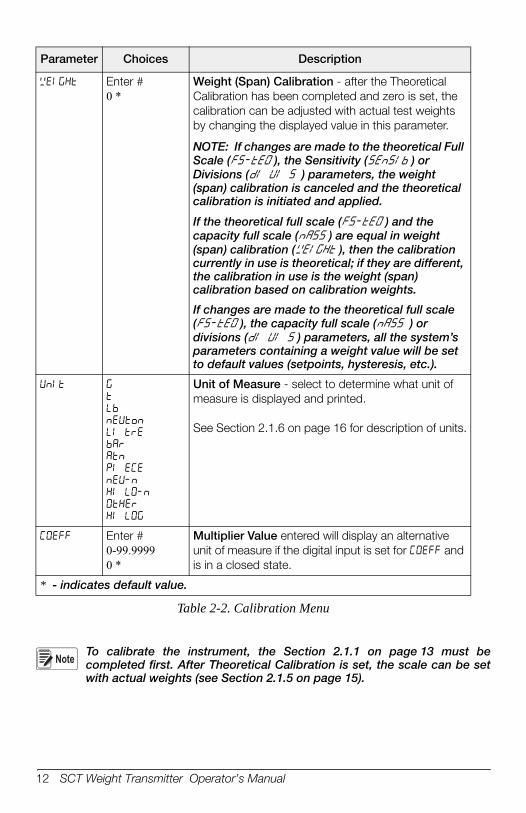
Enter #0 *
Weight (Span) Calibration - after the Theoretical Calibration has been completed and zero is set, the calibration can be adjusted with actual test weights by changing the displayed value in this parameter.
NOTE: If changes are made to the theoretical Full Scale ( ), the Sensitivity ( ) or Divisions () parameters, the weight (span) calibration is canceled and the theoretical calibration is initiated and applied.
If the theoretical full scale ( ) and the capacity full scale ( ) are equal in weight (span) calibration ( ), then the calibration currently in use is theoretical; if they are different, the calibration in use is the weight (span) calibration based on calibration weights.
If changes are made to the theoretical full scale ( ), the capacity full scale () or divisions ( ) parameters, all the system’s parameters containing a weight value will be set to default values (setpoints, hysteresis, etc.).
Unit of Measure - select to determine what unit of measure is displayed and printed.
See Section 2.1.6 on page 16 for description of units.
Enter #0-99.99990 *
Multiplier Value entered will display an alternative unit of measure if the digital input is set for and is in a closed state.
* - indicates default value.
Parameter Choices Description
Table 2-2. Calibration Menu
Note
Configuration 13
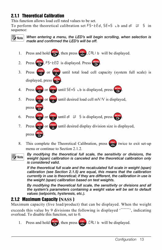
2.1.1 Theoretical CalibrationThis function allows load cell rated values to be set.To perform the theoretical calibration set , and insequence:
When entering a menu, the LED’s will begin scrolling, when selection ismade and confirmed the LED’s will be off.
1. Press and hold , then press , will be displayed.
2. Press , is displayed. Press .
3. Press or until total load cell capacity (system full scale) is
displayed, press .
4. Press or until is displayed, press .
5. Press or until desired load cell mV/V is displayed,
press .
6. Press or until is displayed, press .
7. Press or until desired display division size is displayed,
press .
8. This complete the Theoretical Calibration, press twice to exit set-upmenu or continue to Section 2.1.2.By modifying the theoretical full scale, the sensitivity or divisions, theweight (span) calibration is canceled and the theoretical calibration onlyis considered valid.If the theoretical full scale and the recalculated full scale in weight (span)calibration (see Section 2.1.5) are equal, this means that the calibrationcurrently in use is theoretical; if they are different, the calibration in use isthe weight (span) calibration based on test weights.By modifying the theoretical full scale, the sensitivity or divisions and allthe system’s parameters containing a weight value will be set to defaultvalues (setpoints, hysteresis, etc.).
2.1.2 Maximum Capacity (NASS )Maximum capacity (live load/product) that can be displayed. When the weight
exceeds this value by 9 divisions the following is displayed ‘------’, indicatingoverload. To disable this function, set to 0.
1. Press and hold , then press . will be displayed.
Note
MENU0
ESC
MENU MENU
TARE PRINT
MENU
TARE PRINT MENU
TARE PRINT
MENU
TARE PRINT MENU
TARE PRINT
MENU
0ESC
Note
MENU0
ESC

14 SCT Weight Transmitter Operator’s Manual
2. Press , is displayed.
3. Press or until is displayed, press . LED’s will beginscrolling.
4. Press or until desired capacity is displayed, press .
5. Press twice to exit set-up menu.
2.1.3 Zero SettingPerform this procedure after having set the Section 2.1.1 on page 13.
This menu may also be accessed directly from the weight display, press
and hold for 3 seconds.
1. Press and hold , then press . will be displayed.
2. Press , is displayed.
3. Press or until is displayed, press .
4. The weight value to be set to zero is displayed. In this phase all of the LEDs
are flashing. Press , the weight is set to zero (the value is stored to thepermanent memory).
5. Press twice to exit set-up menu.
Press to display the accumulated deadload that has been zeroed offby the instrument, displaying the sum of all of the previous zero settings.
2.1.4 Zero Value Manual EntryPerform this procedure only if it is not possible to reset theweighed structure tare, for example because it contains productthat can not be unloaded.
Set in this parameter the estimated zero value.
1. Press and hold , then press . will be displayed.
2. Press , is displayed.
3. Press or until is displayed, press . LED’s will beginscrolling.
4. Press or until desired dead load is displayed, press .
5. Press twice to exit set-up menu.
MENU
TARE PRINT MENU
TARE PRINT MENU
0ESC
Note0
ESC
MENU0
ESC
MENU
TARE PRINT MENU
MENU
0ESC
NoteTARE
IMPORTANT
MENU0
ESC
MENU
TARE PRINT MENU
TARE PRINT MENU
0ESC

Configuration 15
2.1.5 Weight (Span) Calibration (With Test Weights)After performing Section 2.1.1 on page 13 and Section 2.1.3 on page 14, this functionallows correct calibration to be done using test weights of known value, if necessary,any deviations of the indicated value from the correct value to be corrected.
1. Load the test weight onto the scale, use as high a percentage of themaximum quantity to be weighed as possible.
2. Press and hold , then press . will be displayed.
3. Press , is displayed.
4. Press or until is displayed, press .
5. The value of the weight currently on the system will be flashing on thedisplay. All the LEDs are off. (If adjustment is not required, skip to step 8.)
6. Adjust the value on display to match weight loaded on the scale if necessary,
by pressing or . The LED’s will begin scrolling.
7. Press , the new set weight will appear with all the LEDs flashing.
8. Press again, will be displayed.
9. Press twice to exit set-up menu.
Example: For a system of maximum capacity of 1000 kg and 1 kg division, two test weightsare available, one 500 kg and one 300 kg. Load both weights onto the system andcorrect the indicated weight to 800. Now remove the 300 kg weight, the systemmust show 500; remove the 500 kg weight, too; the system must read zero. If thisdoes not happen, it means that there is a mechanical problem affecting the systemlinearity.
Identify and correct any mechanical problems before repeatingthe procedure.
If theoretical full scale and recalculated full scale in weight (span)calibration are equal, it means that the theoretical calibration is currentlyin use; otherwise, the weight (span) calibration based on test weights is inuse.If the correction made changes the previous full scale for more than 20%,all the parameters with settable weight values are reset to default values.
Linearization Option On Max 5 Points:It is possible to perform a linearization of the weight repeating the above-describedprocedure up to a maximum of five points, using five different test weights.
The procedure ends by pressing or after entering the fifth value; at this point itwill no longer be possible to change the calibration value, but only to perform a newweight (span) calibration. To perform a new calibration, should return to the weightdisplay and then re-entering into the calibration menu.
MENU0
ESC
MENU
TARE PRINT MENU
TARE PRINT
MENU
MENU
0ESC
IMPORTANT
Note
0ESC
16 SCT Weight Transmitter Operator’s Manual
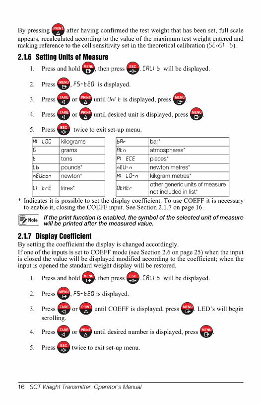
By pressing after having confirmed the test weight that has been set, full scaleappears, recalculated according to the value of the maximum test weight entered andmaking reference to the cell sensitivity set in the theoretical calibration ().
2.1.6 Setting Units of Measure1. Press and hold , then press . will be displayed.
2. Press , is displayed.
3. Press or until is displayed, press .
4. Press or until desired unit is displayed, press .
5. Press twice to exit set-up menu.
* Indicates it is possible to set the display coefficient. To use COEFF it is necessaryto enable it, closing the COEFF input. See Section 2.1.7 on page 16.
If the print function is enabled, the symbol of the selected unit of measurewill be printed after the measured value.
2.1.7 Display CoefficientBy setting the coefficient the display is changed accordingly.If one of the inputs is set to COEFF mode (see Section 2.6 on page 25) when the inputis closed the value will be displayed modified according to the coefficient; when theinput is opened the standard weight display will be restored.
1. Press and hold , then press . will be displayed.
2. Press , is displayed.
3. Press or until COEFF is displayed, press . LED’s will beginscrolling.
4. Press or until desired number is displayed, press .
5. Press twice to exit set-up menu.
kilograms bar* grams atmospheres* tons pieces* pounds* newton metres* newton* kikgram metres*
litres* other generic units of measure not included in list*
MENU0
ESC
MENU
TARE PRINT MENU
TARE PRINT MENU
0ESC
Note
MENU0
ESC
MENU
TARE PRINT MENU
TARE PRINT MENU
0ESC
Configuration 17
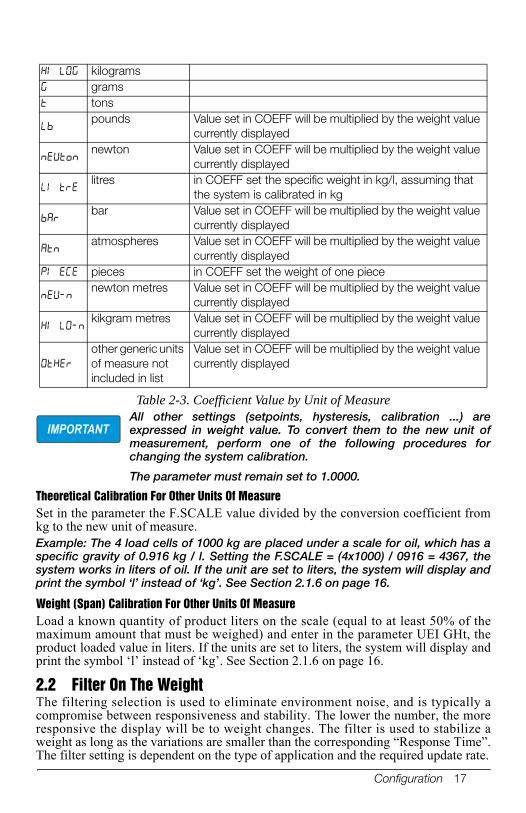
All other settings (setpoints, hysteresis, calibration ...) areexpressed in weight value. To convert them to the new unit ofmeasurement, perform one of the following procedures forchanging the system calibration.
The parameter must remain set to 1.0000.
Theoretical Calibration For Other Units Of MeasureSet in the parameter the F.SCALE value divided by the conversion coefficient fromkg to the new unit of measure.Example: The 4 load cells of 1000 kg are placed under a scale for oil, which has aspecific gravity of 0.916 kg / l. Setting the F.SCALE = (4x1000) / 0916 = 4367, thesystem works in liters of oil. If the unit are set to liters, the system will display andprint the symbol ‘l’ instead of ‘kg’. See Section 2.1.6 on page 16.
Weight (Span) Calibration For Other Units Of MeasureLoad a known quantity of product liters on the scale (equal to at least 50% of themaximum amount that must be weighed) and enter in the parameter UEI GHt, theproduct loaded value in liters. If the units are set to liters, the system will display andprint the symbol ‘l’ instead of ‘kg’. See Section 2.1.6 on page 16.
2.2 Filter On The WeightThe filtering selection is used to eliminate environment noise, and is typically acompromise between responsiveness and stability. The lower the number, the moreresponsive the display will be to weight changes. The filter is used to stabilize aweight as long as the variations are smaller than the corresponding “Response Time”.The filter setting is dependent on the type of application and the required update rate.
kilograms grams tons
pounds Value set in COEFF will be multiplied by the weight value
currently displayed
newton Value set in COEFF will be multiplied by the weight value
currently displayed
litres in COEFF set the specific weight in kg/l, assuming that
the system is calibrated in kg
bar Value set in COEFF will be multiplied by the weight value
currently displayed
atmospheres Value set in COEFF will be multiplied by the weight value
currently displayed pieces in COEFF set the weight of one piece
newton metres Value set in COEFF will be multiplied by the weight value
currently displayed
kikgram metres Value set in COEFF will be multiplied by the weight value
currently displayed
other generic units of measure not included in list
Value set in COEFF will be multiplied by the weight value currently displayed
Table 2-3. Coefficient Value by Unit of Measure
IMPORTANT
18 SCT Weight Transmitter Operator’s Manual
Setting this parameter allows a stable weight display to be obtained. To increase theeffect (weight more stable), increase the value.
1. Press and hold , then press . will be displayed.
2. Press or until is displayed, press . LED’s will beginscrolling.
3. Press or until desired filter value is displayed, press .
4. The weight is displayed (all LED’s will be flashing) and the displayed
stability can be experimentally verified. Press .
5. If stability is not satisfactory, press , this returns indicator to option and the filter may be modified again until an optimum result isachieved.
6. Press to exit set-up menu.
The filter enables to stabilize a weight as long as its variations are smallerthan the corresponding “Response Time”. It is necessary to set this filteraccording to the type of application and to the full scale value set.
Filter ValueResponse times
[ms]Display and serial port refresh frequency
[Hz]0 80 801 190 802 260 403 450 264* 900 135 1700 136 2500 137 4200 108 6000 109 7500 5
* indicates default value.
Table 2-4. Filter Settings
MENU0
ESC
TARE PRINT MENU
TARE PRINT MENU
MENU
MENU
0ESC
Note

Configuration 19
2.3 Zero Parameters
1. Press and hold , then press . will be displayed.
2. Press or until is displayed, press .
2-1. Press or until desired parameter is displayed, press . The
currently programmed value is displayed and LED’s will be scrolling.
3. Press or until desired value is displayed, press .
4. Press twice to exit set-up menu.
Parameter Choices Description
Enter #0-max full scale300 *Considered decimals: 300 – 30.0 – 3.00 – 0.300
Resettable Weight setting for small weight change.Indicates the maximum weight value resettable by external contact, keypad or serial protocol
Enter #0 - max 20% of full scale0 *
Automatic zero setting at power-onIf when indicator is powered on the weight value is lower than the value set in this parameter and does not exceed the 0 SEt value, the weight is reset. To disable this function set to 0.
nOnE *1-5
Zero trackingWhen the zero weight value is stable and, after a second, it deviates from zero by a figure in divisions smaller or equal to the figure in divisions set in this parameter, the weight is set to zero. To disable this function, set to none
Example: if the parameter dI UI S is set to 5and trAC 0 is set to 2, the weight will beautomatically set to zero for variationssmaller than or equal to 10 (dI UI S x trAC 0 ).
* - indicates default value.
Table 2-5. Zero Parameters Settings
MENU0
ESC
TARE PRINT MENU
TARE PRINT MENU
TARE PRINT MENU
0ESC
20 SCT Weight Transmitter Operator’s Manual
2.4 Analog Output
Parameter Choices Description
4-20 mA *0-20 mA0-10 V0-5 V-10 +10 V-5 +5 V
Selects the analog output type.
See Section 2.4.1 on page 21See Section 2.4.1 on page 21
Enter #GrossNet
Select mode to be tracked, gross or net. If the net function is not active, the analog output varies according to gross weight.
Enter # Set the weight value for the minimum analog output value.NOTE: Only set a value different from zero tolimit the analog output range.
E.G.:: for a full scale value of 10000 kg, a 4 mAsignal at 5000 kg is required, and 20 mA at 10000kg, in this case, instead of zero, set 5000 kg.
Enter # Set the weight value for the maximum analog output value; it must correspond to the value set in the PLC program (default: calibration full scale). E.g.: if using a 4-20 mA output and in the PLCprogram a 20 mA = 8000 kg is desired, set theparameter to 8000.
Analog output correction to zero: if necessary adjust the analog output, allowing the PLC to indicate 0. The sign ‘-‘ can be set for the last digit on the left. E.g.: For a 4-20 mA output and a minimumanalog setting, the PLC or tester reads 4.1 mA.Set the parameter to 3.9 to obtain 4.0 on the PLCor tester. (See Section 2.4.2 on page 21)
Full scale analog output correction: if necessary adjust the analog output, allowing the PLC to indicate the value set in the AnA FS parameter. E.g. For a 4-20 mA output with the analog set tofull scale and the PLC or tester reads 19.9 mA,set the parameter to 20.1 to obtain 20.0 on thePLC or tester. (See Section 2.4.2 on page 21)
* - indicates default value.
Table 2-6. Analog Output Menu
Configuration 21
2.4.1 Soldered JumperFor the output -10 +10 V and -5 +5 V the soldered jumper J7 must be closed:
• Remove the face plate of the instrument by removing the screws that attach it tothe little columns on the printed circuit board.
• On the circuit board, locate the jumper J7, situated above the 3 and 4 terminals atabout mid board.
• Scrape away the solder from the jumper bay, until the copper underneath isuncovered.
• Close the jumper short circuiting the bays, it is also recommended that a smallpiece of copper wire without insulation or a leg wire be used to facilitate theoperation.
2.4.2 Analog Output Type Scale CorrectionsMinimum and maximum values which can be set for the zero and full scalecorrections
The analog output may also be used in the opposite manner, i.e. theweight setting that corresponds to the analog zero may be greater thanthe weight set for the analog full scale. The analog output will increasetowards full scale as the weight decreases; the analog output willdecrease as the weight increases.
E.g.: analog output type having selected 0-10VANA 0 = 10000 ANA FS = 0 Weight = 0 kg analog output = 10 VWeight = 5000 kg analog output = 5 VWeight = 10000 kg analog output = 0 V
Analog Output Type Minimum Maximum 0–10 V -0.150 10.2000–5 V -0.150 5.500
-10 +10 V -10.300 10.200-5 +5 V -5.500 5.5000-20 mA -0.200 22.0004-20 mA -0.200 22.000
Note

22 SCT Weight Transmitter Operator’s Manual
2.5 Serial Communication Settings
Figure 2-3. Serial Communications Menu Structure
According to the chosen protocol only the necessary settings will be displayed insequence.
Parameter Choices Description
(Communitcation Port)
* Disables any type of communication (default).
MODBUS-RTU protocol; possible addresses: from 1 to 99 (see Section 3.6)
ASCII bidirectional protocol; possible addresses: from 1 to 99 (see Section 3.7) NOdU6- NOd td
Continuous weight transmission protocol (see Section 3.8), at the frequency set in HERTZ parameter (from 10 to 300). NOd t(set: PARITY=none, STOP=1) NOd td(set: PARITY=none, STOP=1)
Continuous weight transmission protocol, streams net and gross (see Section 3.9) (set: BAUD=9600,PARITY=none, STOP=1)
Continuous weight transmission protocol, streams net and gross including decimal (see Section 3.9) (set: BAUD=9600,PARITY=none, STOP=1)
Table 2-7. Serial Communications Menu
AddrbAud HErt2 dELAY PArItY StOPrS485
nOnENodbUSASCII
Cont In
rI PHdrI PHdrI Pn
Enter #
96001920038400115200
48002400
30405060
2010
8070
Enter #
EUEnOddnOnE
2345
10
89
76
CALIb FILtEr PArA 0 SErIAL tEStOut-InANA LOG
Configuration 23
(cont) Continuous weight transmission protocol (see Section 3.9)When the remote display is set to gross weight:- if the instrument displays the gross weight, the remotedisplay shows the gross weight.- if the instrument shows the net weight the remote display shows the net weight alternated with the message “net”
bAud
Transmission speed.
*Instruments address
Maximum Transmission Frequency - to be set when the CONTIN transmission protocol is selected. (see Table 2-4 on page 18)
Max setting with min 2400 baud rate
Max setting with min 4800 baud rate
Max setting with min 9600 baud rate
0-200 msec0 *
Delay in milliseconds which elapses before the instrument replies
*
parity noneeven parityodd parity
1 *2
Stop bit
* - indicates default value.
Parameter Choices Description
Table 2-7. Serial Communications Menu

24 SCT Weight Transmitter Operator’s Manual
2.5.1 RS-485 Serial Communication
Figure 2-4. RS-485 Serial Communications
SC
TS
CT
SC
T
RS
485
+R
S48
5 -
max
500
m
RS485 +
RS485 -
PC RS232
RX
+
RX
-
TX
-T
X+
Co
nver
ter
24 V
cc +
-
0 TX
RX
VIN
RS
485
+R
S48
5 -
RS
485
term
inat
ion
34
0 VDC
RS485 +
RS485 -0 VDC
RS485 +
RS485 -0 VDC
5 2 3
2829
3428
2934
2829
J2 J
1

Configuration 25
If the RS-485 network exceeds 100 meters in length or baud-rate over9600 are used, close the two jumpers, called RS-485 termination, toactivate two 120 ohm terminating resistors between the ‘+’ and ‘–’terminals of the line, on the terminal strip of the furthest instrument.Should there be different instruments or converters, refer to the specificmanuals to determine whether it is necessary to connect the above-mentioned resistors.
Direct Connection Between RS-485 And RS-232 Without ConverterSince a two-wire RS-485 output may be used directly on the RS-232 input of a PC orremote display, it is possible to implement instrument connection to an RS-232 port inthe following manner:
This type of connection allows a SINGLE instrument to be used in a ONEWAY mode.
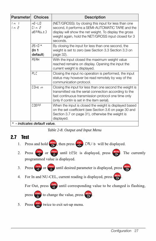
2.6 Outputs And Inputs Configuration
Figure 2-5. Outputs and Inputs Menu Structure
Instrument RS-232RS-485 - RXDRS-485 + GND
Note
Note
OUt 1 OUt 2 In 1 IN 2
CLOSEOPEn
SEt 1PLC
GrOSSNEt
2ErOPEAH
COntI nPLC
nE-lOCOEFF
2Er0PEAH
COntI nPLC
nE-lOCOEFF
CLOSEOPEn
SEt 2
StAbLE
POS/nEGPOSnEG
OFFOn
CALIb FILtEr PArA 0 SErIAL tEStOut-InANA LOG
StAbLEPLC

26 SCT Weight Transmitter Operator’s Manual
Parameter Choices Description
Normally Open: the relay is de-energized and the contact is open when the weight is lower than the programmed setpoint value; it closes when the weight is higher than or equal to the programmed setpoint value.
Normally closed: the relay is energized and the contact is closed when the weight is lower than the programmed setpoint value; it opens when the weight is higher than or equal to the programmed setpoint value.
Number corresponds with OUT 1or 2.The contact will switch on the basis of weight, according to setpoints (see Section 2.8 on page 28) Select:
Gross (default) - the contact will switch on the basis of gross weight.
orNet - the contact will switch on the basis of net weight (If the net function is not active, thecontact will switch on the basis of gross weight).
The contact will not switch on the basis of weight, but is controlled by remote protocol commands.
Relay switching occurs when the weight is stable.
Relay switching occurs for both positive and negative weight values.
Relay switching occurs for positive weight values only. Relay switching occurs for negative weight values only.
Relay switching will not occur if the setpoint value is ‘0’. Setpoint = ’0’ and nodbus=posneg, relay switching
occurs when the weight is ‘0’; the relay will switch again when the weight is different from zero, taking hysteresis into account (both for positive and for negative weights).
Setpoint = ’0’ and nodes=pos, relay switching occurs for a weight higher than or equal to ‘0’, the relay will switch again for values below ‘0’, taking hysteresis into account.
Setpoint = ’0’ and nodes=neg, relay switching occurs for a weight lower than or equal to ‘0’, the relay will switch again for values above ‘0’, taking hysteresis into account.
Table 2-8. Output and Input Menu
Configuration 27
2.7 Test1. Press and hold , then press . will be displayed.
2. Press or until is displayed, press . The currently
programmed value is displayed.
3. Press or until desired parameter is displayed, press .
4. For In and NU-CEL, current reading is displayed, press .
For Out, press until corresponding value to be changed is flashing,
press to change the value, press .
5. Press twice to exit set-up menu.
(NET/GROSS): by closing this input for less than one second, it performs a SEMI-AUTOMATIC TARE and the display will show the net weight. To display the gross weight again, hold the NET/GROSS input closed for 3 seconds.
*(In 1 default)
By closing the input for less than one second, the weight is set to zero (see Section 3.3 Section 3.3 on page 32).
With the input closed the maximum weight value reached remains on display. Opening the input the current weight is displayed.
Closing the input no operation is performed, the input status may however be read remotely by way of the communication protocol.
Closing the input for less than one second the weight is transmitted via the serial connection according to the fast continuous transmission protocol one time only (only if contin is set in the item serial).
When the input is closed the weight is displayed based on the set coefficient (see Section 3.6 on page 30 and Section 3.7 on page 31), otherwise the weight is displayed.
* - indicates default value.
Parameter Choices Description
Table 2-8. Output and Input Menu
MENU0
ESC
TARE PRINT MENU
TARE PRINT MENU
MENU
TARE
PRINT MENU
0ESC

28 SCT Weight Transmitter Operator’s Manual
2.8 Setpoints Programming
1. Press to enter setpoints and hysteresis settings.
2. Press or until desired setpoint or hysteresis parameter is
displayed, press .
3. Press or until desired value is displayed, press .
4. Press to exit setpoints and hysteresis settings.
These values are set to zero if the calibration is changed significantly (seeSection 2.1.1 on page 13 and Section 2.1.5 on page 15).
Parameter Choices Description
N/A Input Test - for each open input 0 is displayed, 1 is displayed when the input is closed.
0 *1
Output Test - Setting 0 - the corresponding output opens. Setting 1 - the corresponding output closes.
Allows the analog signal to range between the minimum and the maximum values starting from the minimum.
current output test voltage output test
N/A Millivolt Test - displays the load cell response signal in mV with four decimals.
* - indicates default value.
Table 2-9. Test Menu
Parameter Choices Description
0-Full Scale0 *
Setpoint; relay switching occurs when the weight exceed the value set in this parameter. The type of switching is settable (see Section 2.6 on page 25).
0-Full Scale0 *
Hysteresis, value to be subtracted from the setpoint to obtain contact switching for decreasing weight. For example with a setpoint at 100 and hysteresis at 10, the switching occurs at 90 for decreasing weight.
* - indicates default value.
Table 2-10. Setpoints
MENU
TARE PRINT
MENU
TARE PRINT MENU
0ESC
Note
Configuration 29
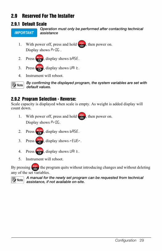
2.9 Reserved For The Installer
2.9.1 Default ScaleOperation must only be performed after contacting technical assistance
1. With power off, press and hold , then power on.Display shows .
2. Press , display shows .
3. Press , display shows .
4. Instrument will reboot.
By confirming the displayed program, the system variables are set with default values.
2.9.2 Program Selection - Reverse:Scale capacity is displayed when scale is empty. As weight is added display will count down.
1. With power off, press and hold , then power on.
Display shows .
2. Press , display shows .
3. Press , display shows .
4. Press , display shows .
5. Instrument will reboot.
By pressing the program quits without introducing changes and without deleting any of the set variables.
A manual for the newly set program can be requested from technical assistance, if not available on-site.
IMPORTANT
0ESC
MENU
MENU
Note
0ESC
MENU
TARE
MENU
0ESC
Note
30 SCT Weight Transmitter Operator’s Manual
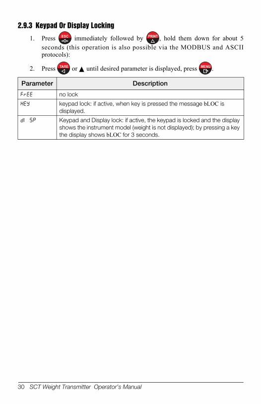
2.9.3 Keypad Or Display Locking
1. Press immediately followed by , hold them down for about 5seconds (this operation is also possible via the MODBUS and ASCIIprotocols):
2. Press or until desired parameter is displayed, press .
Parameter Description
no lock
keypad lock: if active, when key is pressed the message bLOC is displayed.
Keypad and Display lock: if active, the keypad is locked and the display shows the instrument model (weight is not displayed); by pressing a key the display shows bLOC for 3 seconds.
0ESC PRINT
TARE MENU

Operation 31
3.0 Operation
3.1 Semi-Automatic Tare (Net/Gross)The semi-automatic tare value is lost upon instrument power-off.
The semi-automatic tare operation is not allowed if the gross weightis zero.
1. To capture tare and weigh in net mode (SEMI-AUTOMATIC TARE),
close the NET/GROSS input or press for 3 seconds. The
instrument displays the net weight (zero) and the NET LED lights up.
2. To display the gross weight again, keep the NET/GROSS input closed
or press for 3 seconds.
3. This operation can be repeated by the operator to allow the loading ofseveral products.
Press and hold to display the gross weight temporarily. When
is released, the net weight will be displayed again.
3.2 Preset Tare (Subtractive Tare Device)It is possible to manually set a preset tare value to be subtracted from the displayvalue provided that the ≤ max capacity.
1. Press and hold and to display , press .
2. Press or until desired value is displayed, press .
3. Press to exit .
4. After setting the tare value, go back to the weight display, the displayshows the net weight (subtracting the preset tare value) and the NETLED lights up to show that a tare has been entered.
Press and hold for 3 seconds to display the gross weight
temporarily. When is released, the net weight will be displayedagain.
To delete a preset tare and return to the gross weight display:
1. Press hold for 3 seconds or keep the NET/GROSS input (if any)closed for the same length of time (3 seconds). The preset tare value isset to zero. The NET LED is turned off when the gross weight isdisplayed once again.
Note
TARE
TARE
NotePRINT
MENU TARE MENU
TARE PRINT MENU
0ESC
NotePRINT
TARE

32 SCT Weight Transmitter Operator’s Manual
If a semi-automatic tare (net) is entered, it is not possible to accessthe enter preset tare function.If a preset tare is entered, it is still possible to access thesemiautomatic tare (net) function. The two different types of tare areadded.All the semi-automatic tare (net) and preset tare functions will be lostwhen the instrument is turned off.
3.3 Semi-Automatic Zero (Weight Zero-setting For SmallVariations)
By closing the SEMI-AUTOMATIC ZERO input, the weight is set to zero. Thezero setting will be lost when the instrument is turned off.This function is only allowed if the weight is lower than the 0 set value (see 0SET in Section 2.3 on page 19), otherwise the t----- alarm appears and the weightis not set to zero.
3.4 PeakBy keeping the input closed the maximum weight value reached remainsdisplayed. Opening the input the current weight is displayed.
To use this input to view a sudden variation peak, set the FILTER ONTHE WEIGHT (see Section 2.2) to 0.
3.5 AlarmsDisplay Description
Load cell is not connected or is incorrectly connected; the load cell signal exceeds 39 mV; the conversion electronics (A/D converter) is malfunctioning.
Weight display exceeds 110% of the full scale. Internal instrument converter failure; check load cell connections, if
necessary contact Technical Assistance. Weight exceeds the maximum weight by 9 divisions.
Maximum displayable value exceeded (value higher than 999999 or lower than -999999).
Weight too high: zero setting not possible.
This message appears in the test weight setting, in weight (span) calibration, after the fifth test weight value has been entered.
The value set for the parameter is beyond the permitted values; press
to quit the setting mode leaving the previous value unchanged. Examples: -a number of decimals is selected for full scale which exceeds the instrument's display potential;
-value above the maximum setting value; - the weight value set in test weight verification does not match the detected mV increase.
Lock active on menu item, keypad or display.
It’s not possible to display properly the number because is greater than 999999 or less than -999999.
Table 3-1. Alarm Descriptions
Note
Note
0ESC

Operation 33
* For RIP remote displays, if the message exceeds 5 digits the displayreads ------.
If an alarm becomes active the relays open and the analog outputsgo to the lowest possible value according to the following table:
3.6 Modbus-RTU ProtocolThe MODBUS-RTU protocol enables to manage the reading and writing of theregisters listed here below according to the specifications contained in thereference document for this standard Modicon PI-MBUS-300.To select the communication with MODBUS-RTU, refer to Section 2.5 onpage 22.When specifically indicated certain data will be written directly to EEPROMtype memories. This memory has a limited number of writing operations(100.000), therefore unnecessary operations at said locations must be avoided.The instrument, in any case, ensures that no writing occurs if the value to bestored is equal to the stored value.The numerical data listed below are expressed in decimal notation, orhexadecimal notation if preceded by 0x.
Modbus-RTU Data FormatThe data received and transmitted via MODBUS-RTU protocol have thefollowing characteristics:
- 1 start bit- 8 data bits, least significant bit sent first- Instrument settable parity bit- Instrument settable stop bit
ErCEL Er OL Er Ad --------- Er OF t-----
MODE
Bit LSB 76543210 xxxxxxx1
76543210 xxxx1xxx
76543210 xxxxxx1x
76543210 xxxxx1xx
76543210 On gross: xxx1xxxx On net: xx1xxxxx
The response to the zero command is a 'value not valid' error (error code 3)
Status Register MODBUS RTU
ASCII __O-F_ __O-L_ __O-F_ __O-L_ __O-F_ &aa#CR
RIP * __O-F_ __O-L_ __O-F_ __O-L_ __O-F_ __O-F_
HDRIP-N _ERCEL _ER_OL _ER_AD ###### _ER_OF O__SET
CONTIN _ERCEL _ER_OL _ER_AD ^^^^^^ _ER_OF O__SET
Table 3-2. Serial Protocols Alarms
Range 0/20mA 4/20 mA 0/5 V 0/10 V -10/10 V -5/5 VOutput Value
-0.2 mA 3.5 mA -0.5 V -0.5 V 0 V 0 V
Note

34 SCT Weight Transmitter Operator’s Manual
Modbus Supported FunctionsAmong the commands available in the MODBUS-RTU protocol, only the following are used to manage communication with the instruments. Other commands may not be interpreted correctly and could generate errors or system shut-downs:
The interrogation frequency is linked with the preset communication rate (the instrument will stand by for at least 3 bytes before beginning to calculate a possible response to the query). The dELAY parameter (see Section 2.4 on page 20) allows for a further delay in the instrument response, and this directly influences the number of possible queries in the unit of time.For additional information on this protocol, refer to the general technical specification PI_MBUS_300. The functions supported relative to the MODBUS standard are the READ HOLDING REGISTER and the PRESET MULTIPLE REGISTERS.In general, the query and response to and from a slave instrument are organized as follows:
Function 3: Read Holding Registers (Programmable Register Reading)
Tot. bytes = 8
Tot. bytes = 3+2*No. registers+2
Function 16: Preset Multiple Registers (Multiple Register Writing)
Tot. bytes = 7+2*No. registers+2
Tot. bytes = 8No. REGS: Number of registers to write beginning from the address.
FUNCTIONS DESCRIPTION
03 (0x03) Read Holding Register (Programmable Register Reading) 16 (0x10) Preset Multiple Registers (Write Multiple DI Register)
QUERY
Address Function Add. Reg. 1 No. register 2 bytes
A 0x03 0x0000 0x0002 CRC
RESPONSE
Address Function No. bytes Register1 Register 2 2 bytes
A 0x03 0x04 0x0064 0x00C8 CRC
QUERY
Address
Function
Add. reg. 1 No. reg.
No. bytes
Val. reg.1
Val. reg.2 2 bytes
A 0x10 0x0000 0x0002 0x04 0x0000 0x0000 CRC
RESPONSE
Address Function Add. Reg. 1 No. register 2 bytes
A 0x10 0x0000 0x0002 CRC

Operation 35
N° BYTES: Number of bytes transmitted as a value of the registers (2 bytes per register)VAL. REG.: Contents of the register beginning from the first.
The answer contains the register identification modified after the command has been executed.
Communication Error ManagementThe communication strings are controlled by CRC (Cyclical Redundancy Check).In case of a communication error the slave will not respond with any string. The master must allow for a time-out before response reception. If no response is received it infers that a communication error has occurred.In the event of a string received correctly but not executable, the slave responds with an EXCEPTIONAL RESPONSE. The "FUNCTION" field is transmitted with the MSB at 1.
List Of Usable RegistersThe MODBUS-RTU protocol implemented on this instrument can manage amaximum of 32 registers read and written in a single query or response.
R = the register can be read onlyW = the register can be written onlyR/W = the register can be both read and writtenH = high half of the DOUBLE WORD forming the numberL = low half of the DOUBLE WORD forming the number
EXCEPTIONAL RESPONSE
Address Function Code 2 bytes
A Funct + 80h CRC
CODE DESCRIPTION
1 ILLEGAL FUNCTION (Function not valid or not supported) 2 ILLEGAL DATA ADDRESS (The specified data address is not available) 3 ILLEGAL DATA VALUE (The data received have no valid value)
36 SCT Weight Transmitter Operator’s Manual
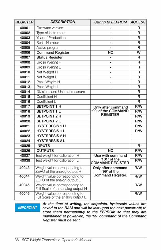
At the time of writing, the setpoints, hysteresis values aresaved to the RAM and will be lost upon the next power-off; tostore them permanently to the EEPROM so that they aremaintained at power-on, the ‘99’ command of the CommandRegister must be sent.
REGISTER DESCRIPTION Saving to EEPROM ACCESS
40001 Firmware version - R 40002 Type of instrument - R 40003 Year of Production - R 40004 Serial Number - R 40005 Active program - R 40006 Command Register NO W 40007 Status Register - R 40008 Gross Weight H - R 40009 Gross Weight L - R 40010 Net Weight H - R 40011 Net Weight L - R 40012 Peak Weight H - R 40013 Peak Weight L - R 40014 Divisions and Units of measure - R 40015 Coefficient H R 40016 Coefficient L R 40017 SETPOINT 1 H Only after command
‘99’ of the COMMAND REGISTER
R/W 40018 SETPOINT 1 L R/W 40019 SETPOINT 2 H R/W 40020 SETPOINT 2 L R/W 40021 HYSTERESIS 1 H R/W 40022 HYSTERESIS 1 L R/W 40023 HYSTERESIS 2 H 40024 HYSTERESIS 2 L 40025 INPUTS - R 40026 OUTPUTS NO R/W 40037 Test weight for calibration H Use with command
‘101’ of the COMMAND REGISTER
R/W 40038 Test weight for calibration L R/W
40043 Weight value corresponding to ZERO of the analog output H
Only after command ‘99’ of the
Command Register.
R/W
40044 Weight value corresponding to ZERO of the analog output L
R/W
40045 Weight value corresponding to Full Scale of the analog output H
R/W
40046 Weight value corresponding to Full Scale of the analog output L
R/W
IMPORTANT
Operation 37
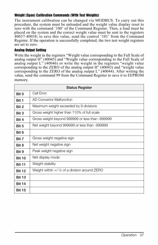
Weight (Span) Calibration Commands (With Test Weights)The instrument calibration can be changed via MODBUS. To carry out thisprocedure, the system must be unloaded and the weight value display reset tozero with the command ‘100’ of the Command Register. Then, a load must beplaced on the system and the correct weight value must be sent to the registers40037-40038; to save this value, send the control ‘101’ from the CommandRegister. If the operation is successfully completed, the two test weight registersare set to zero.
Analog Output SettingWrite the weight in the registers “Weight value corresponding to the Full Scale ofanalog output H” (40045) and “Weight value corresponding to the Full Scale ofanalog output L” (40046) or write the weight in the registers “weight valuecorresponding to the ZERO of the analog output H” (40043) and “weight valuecorresponding to the ZERO of the analog output L” (40044). After writing thevalue, send the command 99 from the Command Register to save it to EEPROMmemory.
Status Register
Bit 0 Cell Error
Bit 1 AD Convertor Malfunction
Bit 2 Maximum weight exceeded by 9 divisions
Bit 3 Gross weight higher than 110% of full scale
Bit 4 Gross weight beyond 999999 or less than -999999
Bit 5 Net weight beyond 999999 or less than -999999
Bit 6
Bit 7 Gross weight negative sign
Bit 8 Net weight negative sign
Bit 9 Peak weight negative sign
Bit 10 Net display mode
Bit 11 Weight stability
Bit 12 Weight within +/-¼ of a division around ZERO
Bit 13
Bit 14
Bit 15
38 SCT Weight Transmitter Operator’s Manual
The output status can be read at any time but can be set (written)only if the output has been set as or (see Section 2.6 Section 2.6 onpage 25); otherwise, the outputs will be managed according to thecurrent weight status with respect to the relevant setpoints.
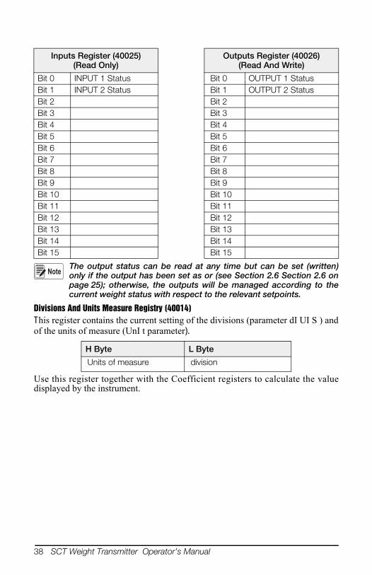
Divisions And Units Measure Registry (40014)This register contains the current setting of the divisions (parameter dI UI S ) andof the units of measure (UnI t parameter).
Use this register together with the Coefficient registers to calculate the valuedisplayed by the instrument.
Inputs Register (40025)(Read Only)
Outputs Register (40026)(Read And Write)
Bit 0 INPUT 1 Status Bit 0 OUTPUT 1 Status Bit 1 INPUT 2 Status Bit 1 OUTPUT 2 Status Bit 2 Bit 2 Bit 3 Bit 3 Bit 4 Bit 4 Bit 5 Bit 5 Bit 6 Bit 6 Bit 7 Bit 7 Bit 8 Bit 8 Bit 9 Bit 9 Bit 10 Bit 10 Bit 11 Bit 11 Bit 12 Bit 12 Bit 13 Bit 13 Bit 14 Bit 14 Bit 15 Bit 15
H Byte L Byte
Units of measure division
Note
Operation 39
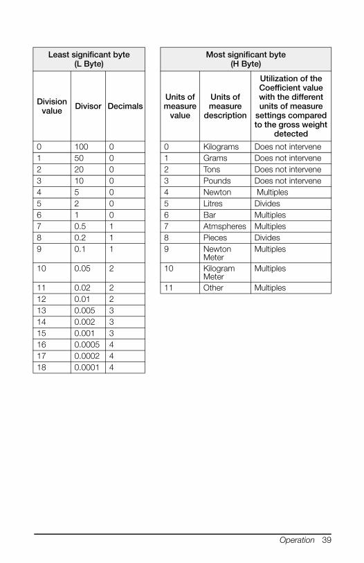
Least significant byte(L Byte)
Most significant byte(H Byte)
Division value Divisor Decimals
Units of measure
value
Units of measure
description
Utilization of the Coefficient value with the different units of measure
settings compared to the gross weight
detected
0 100 0 0 Kilograms Does not intervene 1 50 0 1 Grams Does not intervene 2 20 0 2 Tons Does not intervene 3 10 0 3 Pounds Does not intervene 4 5 0 4 Newton Multiples 5 2 0 5 Litres Divides 6 1 0 6 Bar Multiples 7 0.5 1 7 Atmspheres Multiples 8 0.2 1 8 Pieces Divides 9 0.1 1 9 Newton
Meter Multiples
10 0.05 2 10 Kilogram Meter
Multiples
11 0.02 2 11 Other Multiples 12 0.01 2 13 0.005 3 14 0.002 3 15 0.001 3 16 0.0005 4 17 0.0002 4 18 0.0001 4
40 SCT Weight Transmitter Operator’s Manual
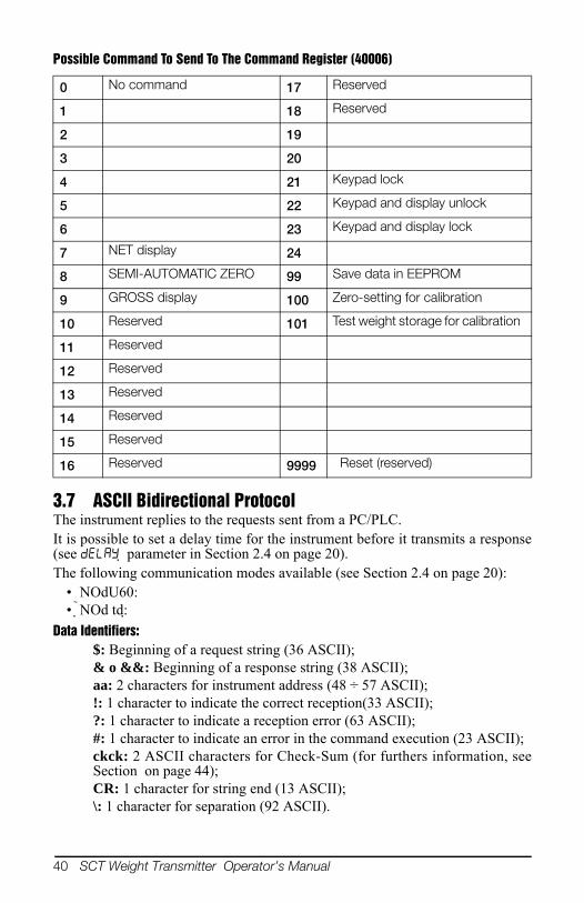
Possible Command To Send To The Command Register (40006)
3.7 ASCII Bidirectional ProtocolThe instrument replies to the requests sent from a PC/PLC.It is possible to set a delay time for the instrument before it transmits a response(see parameter in Section 2.4 on page 20).The following communication modes available (see Section 2.4 on page 20):
• NOdU60: • NOd td:
Data Identifiers:$: Beginning of a request string (36 ASCII);& o &&: Beginning of a response string (38 ASCII);aa: 2 characters for instrument address (48 ÷ 57 ASCII);!: 1 character to indicate the correct reception(33 ASCII);?: 1 character to indicate a reception error (63 ASCII);#: 1 character to indicate an error in the command execution (23 ASCII);ckck: 2 ASCII characters for Check-Sum (for furthers information, seeSection on page 44);CR: 1 character for string end (13 ASCII);\: 1 character for separation (92 ASCII).
0 No command 17 Reserved
1 18 Reserved
2 19
3 20
4 21 Keypad lock
5 22 Keypad and display unlock
6 23 Keypad and display lock
7 NET display 24
8 SEMI-AUTOMATIC ZERO 99 Save data in EEPROM
9 GROSS display 100 Zero-setting for calibration
10 Reserved 101 Test weight storage for calibration
11 Reserved
12 Reserved
13 Reserved
14 Reserved
15 Reserved
16 Reserved 9999 Reset (reserved)

Operation 41
Setpoint Values Setting:The PC transmits: $aaxxxxxxyckckCRin which:
xxxxxx = 6 characters for the setpoint value (48 ÷ 57 ASCII);y = A (set the value in the Setpoint 1)y = B (set the value in the Setpoint 2)
Possible instrument responses:- correct reception: &&aa!\ckckCR- incorrect reception: &&aa?\ckckCR
Setpoints Storage Into EEPROM Memory:The setpoints value relevant to the two setpoints programmed via the PC arestored to the RAM volatile memory and lost upon instrument power off. It isnecessary to send a special command to save them permanently in the EEPROMmemory. Please note that the number of writes allowed in the EEPROM memoryis limited (about 100000).The PC transmits: $aaMEMckckCRPossible instrument responses:
- correct reception: &&aa!\ckckCR- incorrect reception: &&aa?\ckckCR
Reading Weight, The Setpoint And The Peak (If Present) From The Pc:The PC transmits: $aajckckCRin which:
j = a to read setpoint 1j = b to read setpoint 2j = t to read gross weightj = n to read net weightj = p to read the gross weight peak if the ASCII parameter is set as NOdU60; if, instead the ASCII parameter is set on NOd td the
gross weight will be read. To read the points, set the FS_tE0 equal to 50000.
Possible instrument responses:- correct reception: &aaxxxxxxj\ckckCR- incorrect reception: &&aa?\ckckCR- if the peak is not configured: &aa#CR
in which: xxxxxx = 6 value characters of the required weight.
In case of negative weight, the first character on the left acquires thevalue « - » (minus sign - ASCII 45).
In case of weight value is under -99999, the minus sign (‘-‘) is sent alternatedwith the most significant figure.
Note
42 SCT Weight Transmitter Operator’s Manual
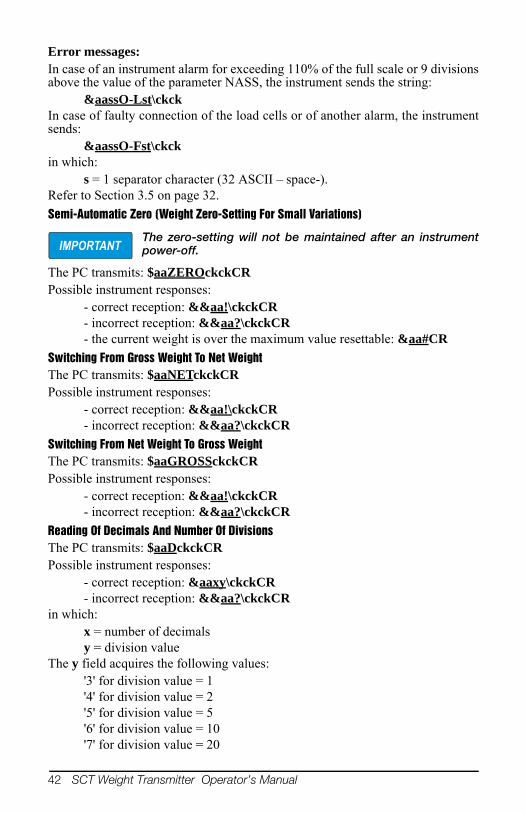
Error messages:In case of an instrument alarm for exceeding 110% of the full scale or 9 divisionsabove the value of the parameter NASS, the instrument sends the string:
&aassO-Lst\ckckIn case of faulty connection of the load cells or of another alarm, the instrumentsends:
&aassO-Fst\ckckin which:
s = 1 separator character (32 ASCII – space-).Refer to Section 3.5 on page 32.
Semi-Automatic Zero (Weight Zero-Setting For Small Variations)
The zero-setting will not be maintained after an instrumentpower-off.
The PC transmits: $aaZEROckckCRPossible instrument responses:
- correct reception: &&aa!\ckckCR- incorrect reception: &&aa?\ckckCR- the current weight is over the maximum value resettable: &aa#CR
Switching From Gross Weight To Net WeightThe PC transmits: $aaNETckckCRPossible instrument responses:
- correct reception: &&aa!\ckckCR- incorrect reception: &&aa?\ckckCR
Switching From Net Weight To Gross WeightThe PC transmits: $aaGROSSckckCRPossible instrument responses:
- correct reception: &&aa!\ckckCR- incorrect reception: &&aa?\ckckCR
Reading Of Decimals And Number Of DivisionsThe PC transmits: $aaDckckCRPossible instrument responses:
- correct reception: &aaxy\ckckCR- incorrect reception: &&aa?\ckckCR
in which: x = number of decimalsy = division value
The y field acquires the following values:'3' for division value = 1'4' for division value = 2'5' for division value = 5'6' for division value = 10'7' for division value = 20
IMPORTANT

Operation 43
'8' for division value = 50'9' for division value = 100
Zero Setting(See Section 2.1.3)The PC transmit the following ASCII string containing the zeroing command:$aazckckCRin which:
z = weight zeroing command (122 ASCII)Possible instrument responses:
- correct reception: &aaxxxxxxt\ckckCR- incorrect reception: &&aa?\ckckCR- If the instrument is not in gross weight displaying condition, the response is: &aa#CR
in which:xxxxxx = 6 characters for the required weight value;t = weight identification code (116 ASCII).
Example: Weight zero setting for instrument with address 2:For the calibration, make sure that the scale is empty and the instrumentmeasures a corresponding mV signal.
query: $02z78(Cr) response: &02000000t\76(Cr)In case of correct weight zero setting the read value (response) must be 0 (in thestring “000000”).
The zero values are stored to the EEPROM memory, pleasenote that the number of writes allowed is limited (about100000). If it is necessary to reset the weight quite often, it isrecommended to perform it by PC or PLC program, keepingin mind the weight deviation respect to the zero instrument.
Weight (Span) Calibration (With Test Weights)(See Section 2.1.5)After having performed the ZERO SETTING (see Section 2.1.3 on page 14), thisfunction allows correct calibration to be done using test weights of known valueand, if necessary, any deviations of the indicated value from the correct value tobe corrected.Load onto the weighing system a test weight, Load the test weight onto the scale,use as high a percentage of the maximum quantity to be weighed as possible.Otherwise make sure that the instrument measures a corresponding mV signal.The PC sends the following ASCII string containing the calibration command:
$aasxxxxxxckckCRin which:
s = calibration command (115 ASCII)xxxxxx = 6 characters for test weight value.
Possible instrument responses:- correct reception: &aaxxxxxxt\ckckCR- incorrect reception or full scale equal to zero: &&aa?\ckckCR
IMPORTANT

44 SCT Weight Transmitter Operator’s Manual
in which: t = gross weight identification code (116 ASCII).xxxxxx = 6 characters to indicate the current weight value.
In case of correct calibration, the read value must be equal to test weight.Example: Calibration for instrument with address 1 and test weight of 20000 kg:
query: $01s02000070(Cr) response: &01020000t\77(Cr)In case of correct calibration the read value has to be “020000”.
Keypad Lock (Access Protection To The Instrument)The PC transmits: $aaKEYckckCRPossible instrument responses:
- correct reception: &&aa!\ckckCR- incorrect reception: &&aa?\ckckCR
Keypad UnlockThe PC transmits: $aaFREckckCRPossible instrument responses:
- correct reception: &&aa!\ckckCR- incorrect reception: &&aa?\ckckCR
Display And Keypad LockThe PC transmits: $aaKDISckckCRPossible instrument responses:
- correct reception: &&aa!\ckckCR- incorrect reception: &&aa?\ckckCR
Check-Sum CalculationThe two ASCII control characters (ckck) are the representation of a hexadecimaldigit in ASCII characters. The check digit is calculated by performing theoperation XOR (exclusive or) 8-bit ASCII codes of the only part of theunderlined string.The procedure to calculate the check- sum is the following:
• Consider only the string characters highlighted with underlining;• Calculate the EXCLUSIVE OR (XOR) of the ASCII codes for the
characters;Example:
• The result of the XOR operation expressed in hexadecimal notation is madeup of 2 hexadecimal digits (numbers from 0 to 9 or letters from A to F). Inthis case the hexadecimal code is 0x75.
• The check-sum inserted in the strings transmitted is made up of the 2characters which represent the result of the XOR operation in hexadecimalnotation (in our example the character " 7 " and the character " 5)
Character Decimal ASCII
Code Hexadecimal ASCII
Code Binary ASCII
Code 0 48 30 00110000 1 49 31 00110001 t 116 74 01110100
XOR = 117 75 01110101

Operation 45
3.8 Fast Continuous Transmission ProtocolThis protocol allows for continuous serial output at high update frequencies. Upto 80 strings per second are transmitted (with a minimum transmission rate of9600 baud). See Section 2-4 on page 18 for limitations.Following communication modes available (see Section 2.4 on page 20):
• NOd t: communication compatible with TX RS-485 instruments; • NOd td: communication compatible with TD RS-485 instruments.• If NOd t is set, the following string is transmitted to PC/PLC: xxxxxxCRLF
in which: xxxxxx = 6 ASCII characters for gross weight (48 ÷ 57 ASCII).CR = 1 character of carriage return (13 ASCII).LF = 1 character of line feed (10 ASCII).
In case of negative weight, the first character on the left acquires the value« - » (minus sign - ASCII 45).In case of error or alarm, the 6 weight characters are replaced by themessages found in Section 3-1 on page 32.
• If NOd td is set, the following string is transmitted to PC/PLC:&TzzzzzzPzzzzzz\ckckCRin which:
& = 1 character of string start (38 ASCII).T = reference character for gross weight.P = reference character for gross weight.zzzzzz = 6 ASCII characters for gross weight (48 ÷ 57 ASCII).\ = 1 character of separation (92 ASCII).ckck = 2 ASCII control characters calculated considering that thecharacters between & and \ are excluded. The control value is obtained bycarrying out the XOR (or exclusive) operation for the 8 bit ASCII codes ofthe characters considered. A character expressed in hexadecimal is thusobtained, with 2 digits which may acquire values from “0” to “9” and from“A” to “F”. “ckck” is the ASCII code of the two hexadecimal digits.CR = 1 character for string end (13 ASCII).In case of negative weight, the first character on the left acquires the value« - » (minus sign - ASCII 45).In case of error or alarm, the 6 gross weight characters are replacedby the messages found in Section 3-1 on page 32.
Fast Transmission Via External Contact: A single string can be transmitted byclosing a digital input, not exceeding 1 second. (see Section 2.6 on page 25 andSection 2.4 on page 20).
46 SCT Weight Transmitter Operator’s Manual
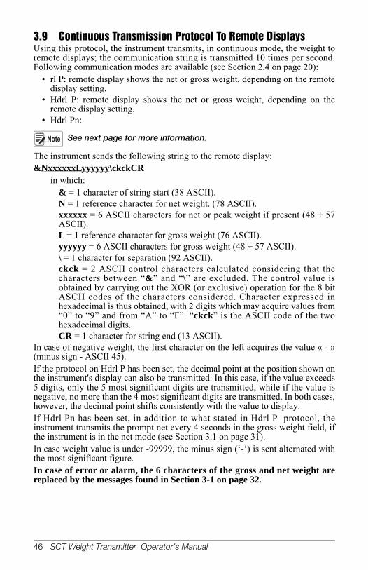
3.9 Continuous Transmission Protocol To Remote DisplaysUsing this protocol, the instrument transmits, in continuous mode, the weight toremote displays; the communication string is transmitted 10 times per second.Following communication modes are available (see Section 2.4 on page 20):
• rl P: remote display shows the net or gross weight, depending on the remotedisplay setting.
• Hdrl P: remote display shows the net or gross weight, depending on theremote display setting.
• Hdrl Pn:
See next page for more information.
The instrument sends the following string to the remote display: &NxxxxxxLyyyyyy\ckckCR
in which: & = 1 character of string start (38 ASCII).N = 1 reference character for net weight. (78 ASCII).xxxxxx = 6 ASCII characters for net or peak weight if present (48 ÷ 57ASCII).L = 1 reference character for gross weight (76 ASCII).yyyyyy = 6 ASCII characters for gross weight (48 ÷ 57 ASCII).\ = 1 character for separation (92 ASCII).ckck = 2 ASCII control characters calculated considering that thecharacters between “&” and “\” are excluded. The control value isobtained by carrying out the XOR (or exclusive) operation for the 8 bitASCII codes of the characters considered. Character expressed inhexadecimal is thus obtained, with 2 digits which may acquire values from“0” to “9” and from “A” to “F”. “ckck” is the ASCII code of the twohexadecimal digits.CR = 1 character for string end (13 ASCII).
In case of negative weight, the first character on the left acquires the value « - »(minus sign - ASCII 45).If the protocol on Hdrl P has been set, the decimal point at the position shown onthe instrument's display can also be transmitted. In this case, if the value exceeds5 digits, only the 5 most significant digits are transmitted, while if the value isnegative, no more than the 4 most significant digits are transmitted. In both cases,however, the decimal point shifts consistently with the value to display.If Hdrl Pn has been set, in addition to what stated in Hdrl P protocol, theinstrument transmits the prompt net every 4 seconds in the gross weight field, ifthe instrument is in the net mode (see Section 3.1 on page 31).In case weight value is under -99999, the minus sign (‘-‘) is sent alternated withthe most significant figure.In case of error or alarm, the 6 characters of the gross and net weight arereplaced by the messages found in Section 3-1 on page 32.
Note

Operation 47
3.10 Interface to Remote DisplayRemote Display (Laser Light)
1. Press and hold , then press . is displayed.
2. Press or until is displayed.
3. Press . is displayed.
4. Press . is displayed.
5. Press or until is displayed. Press .
6. Press twice to exit set-up menu.
Laser Light
E CHAR = CR
LWPOS = 7
LENGTH = 19
Laser Light 1550
S CHAR = SoH
LWPOS = 000008
Laser Light SCT
Connector Pin Connector
J8 (RS-232) 3 RS-485 RX-
5 RS-485 RX+
Table 3-3. Laser Light Setup
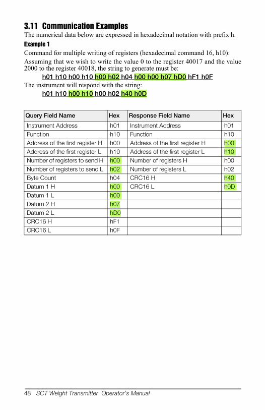
48 SCT Weight Transmitter Operator’s Manual
3.11 Communication ExamplesThe numerical data below are expressed in hexadecimal notation with prefix h.
Example 1Command for multiple writing of registers (hexadecimal command 16, h10):Assuming that we wish to write the value 0 to the register 40017 and the value2000 to the register 40018, the string to generate must be:
h01 h10 h00 h10 h00 h02 h04 h00 h00 h07 hD0 hF1 h0FThe instrument will respond with the string:
h01 h10 h00 h10 h00 h02 h40 h0D
Query Field Name Hex Response Field Name Hex
Instrument Address h01 Instrument Address h01 Function h10 Function h10 Address of the first register H h00 Address of the first register H h00 Address of the first register L h10 Address of the first register L h10 Number of registers to send H h00 Number of registers H h00 Number of registers to send L h02 Number of registers L h02 Byte Count h04 CRC16 H h40 Datum 1 H h00 CRC16 L h0D Datum 1 L h00 Datum 2 H h07Datum 2 L hD0CRC16 H hF1CRC16 L h0F
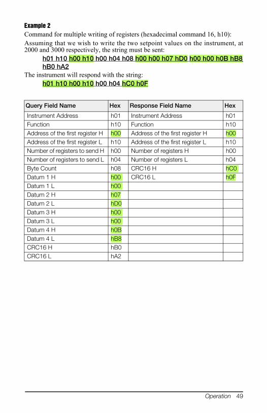
Operation 49
Example 2Command for multiple writing of registers (hexadecimal command 16, h10):Assuming that we wish to write the two setpoint values on the instrument, at2000 and 3000 respectively, the string must be sent:
h01 h10 h00 h10 h00 h04 h08 h00 h00 h07 hD0 h00 h00 h0B hB8hB0 hA2
The instrument will respond with the string:h01 h10 h00 h10 h00 h04 hC0 h0F
Query Field Name Hex Response Field Name Hex
Instrument Address h01 Instrument Address h01 Function h10 Function h10 Address of the first register H h00 Address of the first register H h00 Address of the first register L h10 Address of the first register L h10 Number of registers to send H h00 Number of registers H h00 Number of registers to send L h04 Number of registers L h04 Byte Count h08 CRC16 H hC0 Datum 1 H h00 CRC16 L h0FDatum 1 L h00 Datum 2 H h07Datum 2 L hD0Datum 3 H h00 Datum 3 L h00 Datum 4 H h0BDatum 4 L hB8CRC16 H hB0CRC16 L hA2
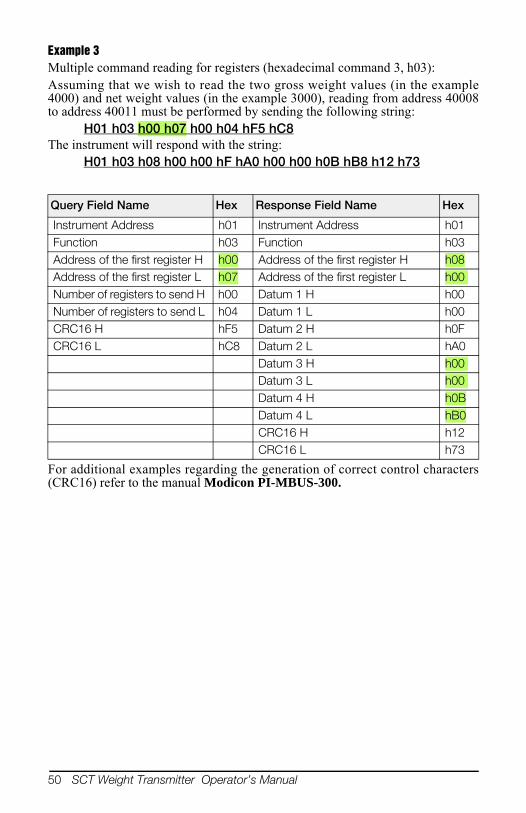
50 SCT Weight Transmitter Operator’s Manual
Example 3Multiple command reading for registers (hexadecimal command 3, h03):Assuming that we wish to read the two gross weight values (in the example4000) and net weight values (in the example 3000), reading from address 40008to address 40011 must be performed by sending the following string:
H01 h03 h00 h07 h00 h04 hF5 hC8The instrument will respond with the string:
H01 h03 h08 h00 h00 hF hA0 h00 h00 h0B hB8 h12 h73
For additional examples regarding the generation of correct control characters(CRC16) refer to the manual Modicon PI-MBUS-300.
Query Field Name Hex Response Field Name Hex
Instrument Address h01 Instrument Address h01 Function h03 Function h03 Address of the first register H h00 Address of the first register H h08Address of the first register L h07 Address of the first register L h00 Number of registers to send H h00 Datum 1 H h00 Number of registers to send L h04 Datum 1 L h00 CRC16 H hF5 Datum 2 H h0FCRC16 L hC8 Datum 2 L hA0
Datum 3 H h00 Datum 3 L h00 Datum 4 H h0BDatum 4 L hB0CRC16 H h12CRC16 L h73
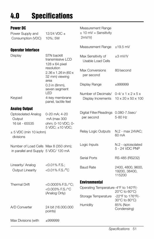
Specifications 51
4.0 Specifications
Power DCPower Supply and 12/24 VDC ± Consumption (VDC) 10%; 5W
Operator InterfaceDisplay STN backlit
transmissive LCD 128 x 64 pixel resolution2.36 x 1.26 in (60 x 32 mm) viewing area0.3 in (8mm), seven segment LED
Keypad 4-key membrane panel, tactile feel
Analog OutputOptoisolated Analog 0-20 mA; 4-20 Output mA (max 300 16 bit - 65535 ohm; 0-10 VDC; 0-
5 VDC; ±10 VDC; ± 5 VDC (min 10 kohm) divisions Number of Load Cells Max 8 (350 ohm); in parallel and Supply 5 VDC/ 120 mA
Linearity/ Analog <0.01% F.S.;
Output Linearity <0.01% F.S./°C
Thermal Drift <0.0005% F.S./°C; <0.003% F.S./°C (Analog Only)
A/D Converter 24 bit (16.000.000 points)
Max Divisions (with ±999999
Measurement Range± 10 mV = Sensitivity 2mV/V)
Measurement Range ±19.5 mV
Max Sensitivity of ±3 mV/V Usable Load Cells
Max Conversions 80/second per second
Display Range ±999999
Number of Decimals/ 0-4/ x 1 x 2 x 5 x Display Increments 10 x 20 x 50 x 100
Digital Filter/Readings 0.080-7.5sec/ per second 5-80 Hz
Relay Logic Outputs N.2 - max 24VAC; 60 mA
Logic Inputs N.2 - optoisolated 5 - 24 VDC PNP
Serial Ports RS-485 (RS232)
Baud Rate 2400, 4800, 9600, 19200, 38400, 115200
EnvironmentalOperating Temperature-4°F to 140°F(-
20°C to 60°C)Storage Temperature -22°F to 176°F(-
30°C to 80°C)Humidity 85% (Non
Condensing)

10/2017 PN 131129 Rev C
230 W. Coleman St. • Rice Lake, WI 54868 • USAU.S. 800-472-6703 • Canada/Mexico 800-321-6703 • International 715-234-9171 • Europe +31 (0)26 472 1319
Rice Lake Weighing Systems is an ISO 9001 registered company. © Rice Lake Weighing Systems Specifications subject to change without notice.
www.ricelake.com