Embed Size (px)
Citation preview

User Manual
SC SYSTEM 3 Portable Touch Surface DJ Controller
EQ
GAIN PITCHA B
FX
LOOP
VINYL
TRIG
DECK
PLAY CUE SYNC TAP
EQ
GAIN PITCHA B
FX
LOOP
VINYL
TRIG
DECK
PLAY CUE SYNC TAP
FX EQ
EQ FX
MASTER
SCS.3d SCS.3dSCS.3m
Important Safety Instructions
• Read and follow the provided instructions before operating the SC System 3. • Adhere to all warnings and security advices, and retain this document for future reference.
Installation: Install the SC System 3 in accordance with the provided instructions
Power Supply: • The SCS.3m should be connected to a power supply outlet only of the voltage and frequency marked on its rear panel and/or its AC adapter.• The power supply cord should be routed so that it is not likely to be walked on or pinched.• The power supply cord of the SCS.3m should be unplugged from the wall outlet when it is to be unused for a long period of time, or during electrical storms.
Placement and Environment:• Locate the SCS.3 controllers away from direct sunlight and any equipment that produces heat such as power supplies, amplifiers, and heaters.• Place your SCS.3 controllers on stable surfaces, away from sources that generate hum or noise, such as transformers, or electric motors.• The location and position of the SCS.3 controllers should not interfere with their proper ventilation. • Do not use the SCS.3 controllers near water. For example, near a bathtub, washbowl, kitchen sink, laundry tub, in a wet basement, or near a swimming pool. • To reduce the risk of fire or electric shock do not expose the equipment to rain or moisture or use it in damp or wet conditions.• Protect the SCS.3 controllers from excessive dirt and dust. • Avoid drinks spillage, tobacco ash, and other contaminants that may affect the performance of the touch surface.• Do not place heavy objects on the SCS.3 controllers surface.
Cleaning: Unplug the SCS.3m from the wall outlet before cleaning. Never use benzine, thinner, or other solventsfor cleaning. Use only a soft damp cloth.
Service:• The SCS.3m contains no user-serviceable parts. • The manufacturer is not responsible for any damage or personal injury resulting from unauthorized user servicing or modifications. Please read the warranty.• The warranty will be void if any unauthorized service by the user is detected.• If service is required, please contact Stanton Tech at +1 954.316.1500 (Option 3)
ii
WARNINg
CAUTION: To reduce the risk of electric shock, do not remove any cover. No user serviceable parts inside. Refer servicing to qualified personnel only.
The lighting flash with arrowhead symbol within the equilateral triangle is intended to alert the user tothe presence of un-insulated “dangerous voltage” within the product enclosure that may be significantenough to constitute a risk of electric shock.
The exclamation point within the equilateral triangle is intended to alert the user to the presence ofimportant operation and maintenance (servicing) instructions in the literature accompanying this appliance.
To reduce the risk of electric shock, do not expose this apparatus to rain or moisture. Ensure that the apparatusis not exposed to splashing and that no objects filled with liquids, such as vases, are placed on the apparatus.
DO NOT OPENRISK OF ELECTRIC SHOCK
CAUTIONTo prevent electric shock, do not use this polarized plug with an extension cord, receptacle or other outletunless the blades can be fully inserted to prevent blade exposure.
CAUTION

Contents
Contents
1. Introduction ................................................................................................................. 11.1. Welcome to the SC System 3 ....................................................................................... 11.2. Overview ..................................................................................................................... 11.3. Unpacking ................................................................................................................... 2
2. Connecting the SCS.3/Installing Virtual DJ .................................................................... 32.1. Remove the Rear Panels ............................................................................................. 32.2. Connect the SC System 3 ............................................................................................. 42.3. Installing Virtual DJ LE....................................................................................................52.4. Configuring for Audio Output.... ................................................................................... 5
3. SCS.3m Description ...................................................................................................... 63.1. SCS.3m –Traditional Mixer Comparisons ................................................................... 6
3.1.1. Channel Pan ................................................................................................... 63.1.2. EQ Section ....................................................................................................... 63.1.3. Channel Fader ................................................................................................. 73.1.4. Crossfader ....................................................................................................... 7
3.2. SCS.3m Top Panel Functional Groups .......................................................................... 83.2.1. Deck Switch ..................................................................................................... 93.2.2. Slider Section .................................................................................................. 103.2.3. EQ/FX Mode Switches ................................................................................... 113.2.4. Channel Fader ................................................................................................ 113.2.5. Button Section ............................................................................................... 123.2.6. Monitor Button .............................................................................................. 123.2.7. Master Mode Button ..................................................................................... 133.2.8. Crossfader ...................................................................................................... 133.2.9. Channel Level Meter ..................................................................................... 143.2.10. Channel Strip ................................................................................................. 14
4. SCS.3d Description ...................................................................................................... 154.1. SCS.3d – Traditional Deck Comparisons .................................................................... 15
4.1.1. “Platter” Area ................................................................................................ 154.1.2. Pitch Fader ..................................................................................................... 154.1.3. Transport Buttons .......................................................................................... 16
4.2. SCS.3d Top Panel Functional Groups ......................................................................... 164.2.1. Gain/Pitch Sliders .......................................................................................... 174.2.2. Mode Switcher .............................................................................................. 17
4.2.2.1. FX Mode ......................................................................................... 184.2.2.2. EQ Mode ........................................................................................ 184.2.2.3. Loop Mode ..................................................................................... 194.2.2.4. Trigger Mode .................................................................................. 194.2.2.5. Vinyl Mode ..................................................................................... 194.2.2.6. Deck Switcher ................................................................................ 20
4.2.3. Trigger Buttons .............................................................................................. 204.2.4. StanTouch Control Area ................................................................................. 214.2.5. Transport Controls ......................................................................................... 21
4.3. SCS.3d Rear Panel ...................................................................................................... 22
iii
Contents
5. Installing DaRouter®.................................................................................................... 23 Installing and Configuring DaRouter®.......................................................................... 23
5.3. Installing on Windows® ............................................................................................. 235.2.1. Installing DaRouter ........................................................................................ 23
5.4. Installing on OSX® ..................................................................................................... 285.5.1. Installing DaRouter ........................................................................................ 28
5.5. Configuring DaRouter ................................................................................................ 316. Using the SC System 3 for generic MIDI Control .......................................................... 32
6.1. SCS.3m Standalone Configuration ............................................................................. 326.1.1. Selecting MIDI Channel ................................................................................ 326.1.2. Selecting Built-in Presets............................................................................... 336.1.3. Advanced Control of Built-in Presets ............................................................ 34
6.2. SCS.3d Standalone Configuration .............................................................................. 346.2.1. Selecting Presets ........................................................................................... 35
6.3. SC System Configuration ........................................................................................... 356.4. MIDI Learn ................................................................................................................. 35
7. Troubleshooting .......................................................................................................... 368. Specifications .............................................................................................................. 37
Warranty .................................................................................................................... 38
iv
Introduction
1. Introduction
1.1 Welcome to the SC System 3!
Thank you for purchasing the SC System 3, one of the most advanced touch sensitive DJ controlsystems ever created. The SC System 3 integrates touch sensitive technology with Atomix Production’saward winning Virtual DJ LE software to allow you to interact with your music in ways previously notpossible with traditional DJ gear.
With the SC System 3, we hope that you find yourself mixing your favorite songs in a matter of minuteswith the guidance of this manual. Before we begin, please register your SCS.3 controllers. Just go tohttp://www.enterthesystem.com and click on the Product Update Registration link. We look forwardto keeping you informed about the latest presets, firmware updates, new releases, and more…
1.2 Overview
The SC System 3 consists of two decks (SCS.3ds) and a mixer (SCS.3m) that have much of the samecontrols of a traditional two turntable and mixer setup, however they are way more powerful andadvanced. At a fraction of the size and weight of a traditional setup and with minimal moving parts,the SC System 3 is a great solution no matter if you are a seasoned veteran or a beginner DJ.
Atomix Virtual DJ LE software (included in the box) perfectly integrates with the SC System 3. TheSCS.3 controllers not only allow you to mix between four songs, but also allow you to manage yourmusic collection, loop, add effects, and engage Virtual DJ LE's synchronization engine to helpautomatically line up two songs without the years of practice required on a traditional vinyl setup.
Because of the tight interaction between the SCS.3 controllers and Virtual DJ LE, everything thathappens on screen stays in perfect harmony with the light feedback on the controllers, allowing youto mix in low light environments and focus on your performance with confidence.
Main SCS.3 controller features:
• StanTouch controller - it offers a simple tactile way to control sliders and change data or control effects automation• Multi-touch sliders - they allow you to make fast transitions and develop new performance techniques• Inspired by a traditional turntable and mixer layout, enabling scratching / cueing, 3-band EQ, cross fading, level setting, FX control and master/cue functions• 4-deck support - controls up to 4 unique decks or tracks in DJ software • Video mixing support (Full screen output requires upgrade to Virtual DJ Pro)• USB class-compliant - no driver required for Mac® or PC computers• Integrated powered USB hub - up to 4 USB devices can be plugged in• Ability to be bus powered (without USB hub functionality)• Small footprint - the SCS.3 controllers are compact, and fit anywhere a typical 15” laptop will fit• Minimal moving parts ensure that the SC System 3 will not break down or wear over time unlike traditional controllers• Portability - the SCS.3 controllers are easy to carry and can be used hand-held, if desired
Before you start hooking up your new units, let’s check what is in the box!
1
Unpacking
1.3 Unpacking
Please check that you have received the following items:
(1) SCS.3m unit(2) SCS.3d units(1) Power supply (12 VDC)(3) USB cables(1) Headphone Adaptor Cable(1) SC System Quick Start Guide(1) SC System 3 DaRouter/Support CD (With Virtual DJ LE Install)
In addition to the above items, remember that to take advantage of the full potential of the SC System3 you will need a Mac or PC computer (with Internet connection) to check for any potential updatesto Virtual DJ that may provide enhanced functionality, and preferably an audio interface (if you donot own one, you can use the included headphone adaptor cable).
Let’s get started by hooking up the SC System 3.
2
Connect the SC System 3/Installing Virtual DJ
2. Connecting the SCS.3 Controllers
In this section we will briefly describe how to connect the SC System 3.
3
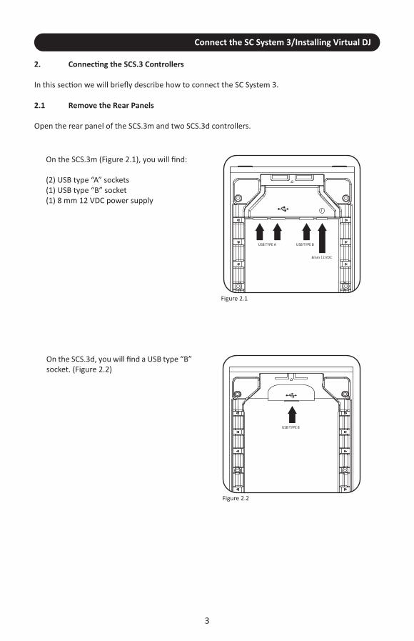
2.1 Remove the Rear Panels
Open the rear panel of the SCS.3m and two SCS.3d controllers.
USB TYPE B
USB TYPE A USB TYPE B
8mm 12 VDC
Figure 2.1
Figure 2.2
On the SCS.3d, you will find a USB type “B”socket. (Figure 2.2)
On the SCS.3m (Figure 2.1), you will find:
(2) USB type “A” sockets (1) USB type “B” socket (1) 8 mm 12 VDC power supply

Connect the SC System 3/Installing Virtual DJ
4
2.2 Connect the SC System 3
A. Connect the USB type “B” connector to the SCS.3m USB “B” socket and the other end of the USB cable to your computer’s USB port.
B. Before connecting other devices, connect the SCS.3m to power.
C. Thanks to the SCS.3m integrated USB hub and the wire management options, you can now connect the two SCS.3d’s either by routing the USB cables through the sides of the SCS.3d’s and SCS.3m, or out the back of the SCS.3d and using the two rear panel USB connectors. The additional two USB sockets can be used to add peripheral devices such as flash storage, other controllers, or any other USB peripheral. (Figure 2.3)
Figure 2.3

5
Installing Virtual DJ LE/Configuring for Audio Output
2.3 Installing Virtual DJ LE
WindowsBefore you can begin using your SCS.3PAK with your computer, you must install the included VirtualDJLE software: 1. Please insert the included Stanton Support disc into your computer's DVD/CD drive. 2. Open the CD to view its contents, Open the folder titled "VIRTUAL DJ", then the folder titled“WINDOWS” and double-click the ".Msi file". 4. Follow the on-screen instructions to finish installing.3. Open VirtualDJ LE by double-clicking the icon on your computer's Desktop (if you created a Desktopshortcut) or by going to Start : All Programs : VirtualDJ.
For more information on how to use VirtualDJ LE, please see the included Quick Start Guide and videoson your support CD.
OSXBefore you can begin using your SCS.3PAK with your computer, you must install the included VirtualDJLE software: 1. Please insert the included Stanton Support disc into your computer's DVD/CD drive. 2. Open the CD to view its contents, Open the folder titled "VIRTUAL DJ", then the folder titled “OSX”and double-click the ".PKG file". 4. Follow the on-screen instructions to finish installing. 5. Open VirtualDJ LE by going to Applications : VirtualDJ.
For more information on how to use VirtualDJ LE, please see the included Quick Start Guide and videoson your support CD.
2.4 Configuring Virtual DJ wth the included Audio Cable for headphone/speaker output
The SC System 3 comes with a special audio cable, which can be used in place of a seperate audiointerface.
While we recommend purchasing an external audio interface for professional use, this cable will allowyou to DJ with just the 1/8” mini-plug output from your computer. For serious DJs that already haveone or more audio interfaces, it still comes in handy as something you can carry around with you asa backup solution, and as an easy to use alternative if you’re just sitting around building playlists anddon’t want to have a bunch of stuff spread out everywhere.
To use the cable and your onboard soundcard, you’ll need to take a minute to configure Virtual DJ LE.
1. First, plug the cable into the Headphone output on your computer.2. Then, plug the leads to your stereo, mixer, or powered speakers to the RCA outputs on the
cable. This will be your main output.3. Next, plug your headphones into the headphone jack on the cable.
Finally, within Virtual DJ LE, under CONFIG->SOUND SETUP, go to OUTPUT and select ‘Headphones’This will send the appropriate signal (Master/Cue) to your speakers and headphones.

SCS.3m Description
3. SCS.3m Description
3.1 SCS.3m – Traditional Mixer Comparisons
The SCS.3m was created to give you control of most common mixer functionality. You can see thatthe layout on the SCS.3m is symmetrical and that we are emulating a 2-channel mixer, similar to atypical DJ mixer. Keeping this comparison in mind will help you to understand the different featuresof the SCS.3m.
Let’s begin by comparing the different control groups on the SCS.3m to their counterparts on atraditional mixer.
6
3.1.1 Channel Pan
3.1.2 EQ Section
The Channel Pan control allows you to move the audio onthat channel left or right in the stereo field. This can beused as an effect, or to compensate for problems either inthe loaded track or the main speakers.
****NOTE: In Virtual DJ, these faders are used to controlthe FILTER or first FX parameter, depending on mode.
(Figure 3.1)
Figure 3.1
1O 1O
LOW MID HIGH LOW MID HIGH
An EQ allows you to manipulate different frequencies. On the SCS.3m, the EQ section is separated into 3 sliders.
Each slider corresponds to a frequency range (Low, Mid,and High). You can use the EQ to make subtle adjustmentsto a track to “match” it to your other track (for instance, ifthe bass is too boomy). Many DJs will mix tracks togethernot just with the volume, but will also lower the bass ofthe incoming track so it blends smoothly with the playingtrack. You can also use the EQs as effects, radicallychanging the sound of a playing track. (Figure 3.2)
Figure 3.2
Channel Fader
7
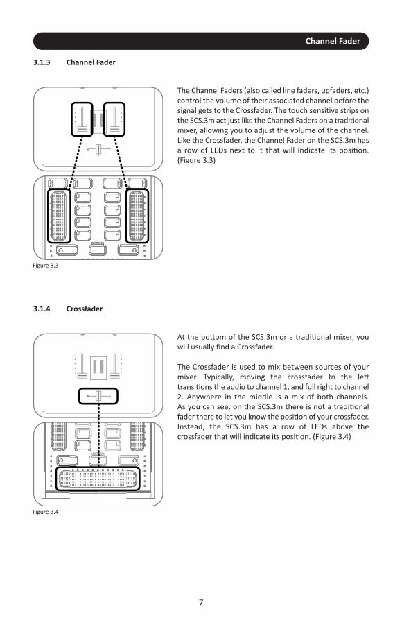
3.1.3 Channel Fader
3.1.4 Crossfader
The Channel Faders (also called line faders, upfaders, etc.)control the volume of their associated channel before thesignal gets to the Crossfader. The touch sensitive strips onthe SCS.3m act just like the Channel Faders on a traditionalmixer, allowing you to adjust the volume of the channel.Like the Crossfader, the Channel Fader on the SCS.3m hasa row of LEDs next to it that will indicate its position.(Figure 3.3)
Figure 3.3
MASTERMASTER
O
1O
O
1O
At the bottom of the SCS.3m or a traditional mixer, youwill usually find a Crossfader.
The Crossfader is used to mix between sources of yourmixer. Typically, moving the crossfader to the lefttransitions the audio to channel 1, and full right to channel2. Anywhere in the middle is a mix of both channels. As you can see, on the SCS.3m there is not a traditionalfader there to let you know the position of your crossfader.Instead, the SCS.3m has a row of LEDs above thecrossfader that will indicate its position. (Figure 3.4)
Figure 3.4
O
1O
O
1O

SCS.3m Top Panel Functional groups
3.2 SCS.3m Top Panel Functional groups
The SCS.3m has 10 functional groups. (Figure 3.5)
8
Let’s read a brief description of each of them.
FX EQ
EQ
EQ
EQ FX
MASTERMASTER
66
Figure 3.5

Deck Switch
3.2.1 Deck Switch
9
FX EQ
EQ
EQ
EQ FX
MASTERMASTER
In some cases, you might also see the Deck Switching buttons used for things like alternative layouts.It really depends on the mapping and the application. In any situation, the Deck Switch buttons allowthe SCS.3m to effectively double its number of controls while maintaining the same small form factor.
Figure 3.6
The Deck Switch button allows for each side of the SCS.3m to beswitched between 2 virtual decks. Each side can be toggledindependently, thus allowing 4 channels to be controlled in aconventional 2-channel design. (Figure 3.6)
In each Deck Switcher, there is a backlit letter (either A and C, or Band D) to indicate which virtual channel that side of the SCS.3m iscontrolling. The SCS.3m will keep current the controls for both decksand update to the latest values when returning to a deck.
This is done by providing a different set of MIDI controls that can beused to map to a different channel in a program such as Virtual DJ,or provide an additional set of controls in other applications. All ofthe controls for all "decks" and modes such as EQ, FX and Masterare transmitted on one channel number so the SCS.3m only takesup one MIDI channel number in your MIDI setup. (Figure 3.7)
Figure 3.7
FX
MASTERMASTER
HOLD
TAP
HOLD
TAP
Slider Section
3.2.2 Slider Section
10
FX EQ
EQ
EQ
EQ FX
MASTERMASTER
Figure 3.8
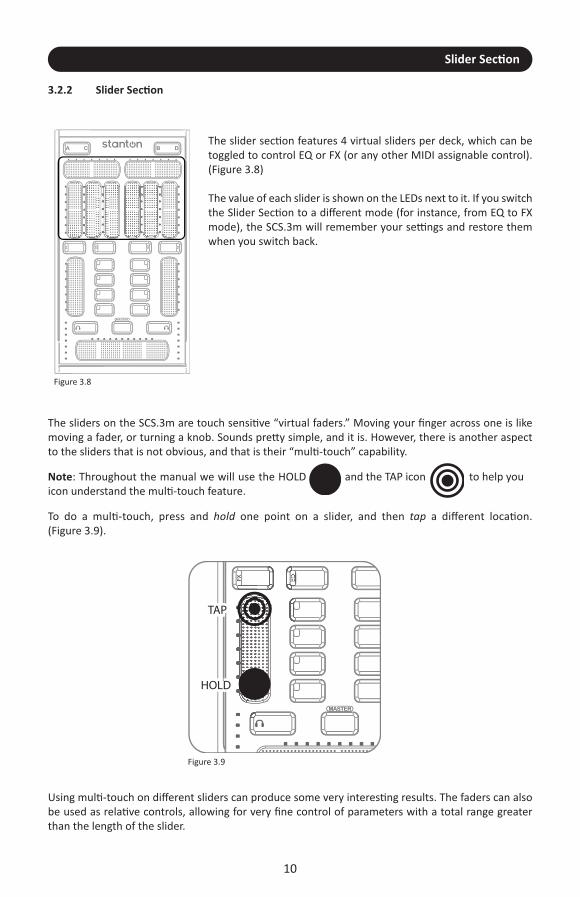
The slider section features 4 virtual sliders per deck, which can betoggled to control EQ or FX (or any other MIDI assignable control).(Figure 3.8)
The value of each slider is shown on the LEDs next to it. If you switchthe Slider Section to a different mode (for instance, from EQ to FXmode), the SCS.3m will remember your settings and restore themwhen you switch back.
Figure 3.9
The sliders on the SCS.3m are touch sensitive “virtual faders.” Moving your finger across one is likemoving a fader, or turning a knob. Sounds pretty simple, and it is. However, there is another aspectto the sliders that is not obvious, and that is their “multi-touch” capability.
Using multi-touch on different sliders can produce some very interesting results. The faders can alsobe used as relative controls, allowing for very fine control of parameters with a total range greaterthan the length of the slider.
Note: Throughout the manual we will use the HOLDicon understand the multi-touch feature.
and the TAP icon to help you
To do a multi-touch, press and hold one point on a slider, and then tap a different location. (Figure 3.9).

EQ/FX Mode Switches
3.2.3 EQ/FX Mode Switches
11
FX EQ
EQ
EQ
EQ FX
MASTERMASTER
Figure 3.10
These buttons will toggle the Slider Section and Button Sectionbetween EQ controls and FX controls. Allows for 4 buttons and 4sliders per deck. When switching modes the latest values for thatmode will be displayed. (Figure 3.10)
3.2.4 Channel Fader
FX EQ
EQ
EQ
EQ FX
MASTERMASTER
Figure 3.11
The Channel Fader is always assigned to control each channel’svolume (even when you are in EQ/FX mode). With StanTouchtechnology, it is easy to do quick kills or gradual fades using thistouch strip.
Like the other SCS.3m sliders, the Channel Fader lets you know itsvalue with the LED strip next to it, and it will remember and recallits value when you switch channels. It is also multi-touch capable.Do you want to do a transform but don’t have a LINE/PHONOswitch? Try holding one finger at the bottom of the fader whiletapping the top of the fader with another. This is easy to pull off withone hand, and accomplishes the same kind of effect. (Figure 3.11)

Button Section
12
3.2.5 Button Section
FX EQ
EQ
EQ
EQ FX
MASTERMASTER
Figure 3.12
The Button Section consists of four buttons with multicolor feedbackfor control of on screen buttons or triggers. These can be assignedto EQ kills, FX engage, or other MIDI assignable features. (Figure 3.12)
The buttons next to each Channel Fader can be assigned to anythingyou want. You might see them controlling the effects in Virtual DJ,or samples and loops in Serato Scratch Live™.
3.2.6 Monitor Button
FX EQ
EQ
EQ
EQ FX
MASTERMASTER
Figure 3.13
The Monitor Button allows for quick and easy toggling of the currentchannel for previewing a song before dropping it into a mix. (Figure 3.13)

Master Mode Button
13
3.2.7 Master Mode Button
FX EQ
EQ
EQ
EQ FX
MASTERMASTER
Figure 3.14
When the Master Mode Button is engaged, the Channel Faders andCrossfader temporarily become controls for monitor volume, master volume, and monitor mix. The VU meters also display themaster levels for checking a clean output signal from your computer.
To enter “Master” mode, press and hold the Master button. The SCS.3m will remain in Master mode as long as you hold yourfinger on the Master button. (Figure 3.14)
3.2.8 Crossfader
FX EQ
EQ
EQ
EQ FX
MASTERMASTER
Figure 3.15
The extended length Crossfader gives extra fine control of blendingbetween channels and more surface to perform multi-touch effectswith two fingers for quickly cutting in and out of channels. (Figure 3.15)
Let’s say you wanted to emulate the sound of a crab scratch or flaresusing the SCS.3m crossfader. While there is not a back stop tobounce against, we can take advantage of multi-touch here and getsomething very similar. Try holding your index finger at the furthestend of the crossfader, and then drumming your other fingers (middle to pinky) on the surface next to it. (Figure 3.16)
MASTERMASTER
HOLD TAP TAP TAP
Figure 3.16

Channel Level Meter
14
3.2.9 Channel Level Meter
FX EQ
EQ
EQ
EQ FX
MASTERMASTER
Figure 3.17
The Channel Level Meter indicates the volume of each channel likea traditional DJ mixer. (Figure 3.17)
3.2.10 Channel Strip
FX EQ
EQ
EQ
EQ FX
MASTERMASTER
Figure 3.18
The Slider, Button, Mode Switchers, Channel Fader, Level Meter, andMonitor Button all constitute a traditional channel strip. The ChannelStrip can be switched between decks A/C on the left side and B/Don the right side of the SCS.3m to control up to 4 software channels.(Figure 3.18)

15
4. SCS.3d Description
4.1 SCS.3d – Traditional Deck Comparisons
The SCS.3d was developed to give you the kind of control normally associated with CD decks, but ina small, portable layout. Just like its more traditional counterparts, the SCS.3d is broken up into 3 mainareas; Platter Area, Pitch Fader, and Transport Buttons. Let’s begin by describing each area.
4.1.1 “Platter” Area
4.1.2 Pitch Fader
The Platter Area is where the user manipulates a song.(Figure 4.1) This is where you put your hand to cue, or manually adjust a track. On a traditional CD player, thesong would be playing off a CD contained in the unit itself.On the SCS.3d, the song would be playing from a softwaredeck on a computer.
Figure 4.1
The Pitch Fader is where you control the playback speedof the deck. (Figure 4.2) It is the single most importantcontrol for beatmixing.
Some DJs constantly “ride” the pitch fader whenbeatmixing songs together, while others set it andmanipulate the platter to make any fine adjustments.Choose the approach that feels right for you.
Figure 4.2
SCS.3d Description
Transport Buttons & Top Panel Functional groups
16
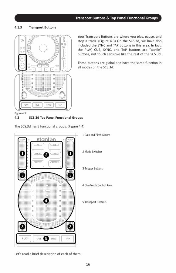
4.1.3 Transport Buttons
Your Transport Buttons are where you play, pause, andstop a track. (Figure 4.3) On the SCS.3d, we have alsoincluded the SYNC and TAP buttons in this area. In fact, the PLAY, CUE, SYNC, and TAP buttons are “tactile”buttons, not touch sensitive like the rest of the SCS.3d.
These buttons are global and have the same function inall modes on the SCS.3d.
Figure 4.3
4.2 SCS.3d Top Panel Functional groups
The SCS.3d has 5 functional groups. (Figure 4.4)
Let’s read a brief description of each of them.

gain/Pitch Sliders
17
4.2.1 gain/Pitch Sliders (Figure 4.5)
Figure 4.5
The Gain Slider is located in the top left corner of the SCS.3d. It controls the gain for whatever deck that SCS.3d is controlling.However, Gain is different than volume. Think of gain as the outputof the deck before it is affected by the volume fader. For example, if a deck is excessively loud (even when you bring your mixer volumedown) you would need to adjust the gain to fix this problem.
The Pitch Fader is located in the top right corner of the SCS.3d. In the DJ world, adjusting pitch actually means adjusting theplayback speed of the track. This is the main tool DJs use forbeatmixing songs together.
To increase the overall accuracy of the SCS.3d pitch faders, we havechanged the type of data the Pitch fader sends out to a relativemessage (instead of absolute) so you have very fine control over thepitch fader in a compact space.
4.2.2 Mode Switcher
Figure 4.6
The “Mode Switcher” section is a group of 6 buttons that changethe way the SCS.3d behaves. (Figure 4.6) Each of these buttonsmakes changes to one or more control areas on the SCS.3d. Because the function of each mode is programmable, the specificchange each mode makes is highly dependent on what DaRouterpreset is being used.
Usually, the Mode Buttons change the way the StanTouch ControlArea and the Trigger Buttons work, but in some cases, other controlareas can be affected as well.
In this section of the manual, we will look at these modes in generalterms. Later on, we will describe how some of these modes workwith the included Virtual DJ LE software, to get you started mixingright away.

FX Mode
18
4.2.2.1 FX Mode
Figure 4.7
FX Mode usually turns the StanTouch Control Area into 3 verticallyaligned “sliders” (or virtual faders). (Figure 4.7) These 3 sliders wouldthen be mapped to the effects functionality in whatever softwareyou are using.
4.2.2.2 EQ Mode
Figure 4.8
Like FX Mode, EQ Mode usually turns the StanTouch Control Areainto 3 vertical sliders. (Figure 4.8) These 3 sliders would then bemapped to a 3 band EQ in your software.
4.2.2.3 Loop Mode
Figure 4.9
Loop Mode changes the StanTouch Control Area into buttons.(Figure 4.9) There are actually 9 distinct button areas in the controlarea, but some presets will combine button areas to make bigger,easier to press buttons. For example, many presets break the ControlArea up into 5 buttons (2 on each side, and one big button in themiddle). These buttons would then be mapped to looping functions(start/stop loop, loop length, etc).
Trigger Mode
19
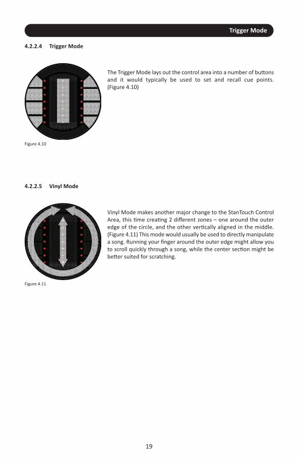
4.2.2.4 Trigger Mode
Figure 4.10
The Trigger Mode lays out the control area into a number of buttonsand it would typically be used to set and recall cue points. (Figure 4.10)
4.2.2.5 Vinyl Mode
Figure 4.11
Vinyl Mode makes another major change to the StanTouch ControlArea, this time creating 2 different zones – one around the outeredge of the circle, and the other vertically aligned in the middle.(Figure 4.11) This mode would usually be used to directly manipulatea song. Running your finger around the outer edge might allow youto scroll quickly through a song, while the center section might bebetter suited for scratching.
Deck Switcher
20
4.2.2.6 Deck Switcher
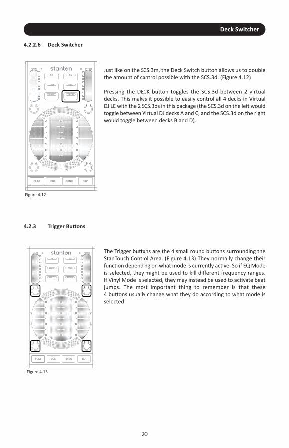
Figure 4.12
Just like on the SCS.3m, the Deck Switch button allows us to doublethe amount of control possible with the SCS.3d. (Figure 4.12)
Pressing the DECK button toggles the SCS.3d between 2 virtualdecks. This makes it possible to easily control all 4 decks in VirtualDJ LE with the 2 SCS.3ds in this package (the SCS.3d on the left wouldtoggle between Virtual DJ decks A and C, and the SCS.3d on the rightwould toggle between decks B and D).
4.2.3 Trigger Buttons
Figure 4.13
The Trigger buttons are the 4 small round buttons surrounding theStanTouch Control Area. (Figure 4.13) They normally change theirfunction depending on what mode is currently active. So if EQ Modeis selected, they might be used to kill different frequency ranges. If Vinyl Mode is selected, they may instead be used to activate beatjumps. The most important thing to remember is that these 4 buttons usually change what they do according to what mode isselected.

StanTouch Control Area
21
4.2.4 StanTouch Control Area
Figure 4.14
The StanTouch Control Area is really the “star” of the show on theSCS.3d, and it is where your hand will be spending most of its time.(Figure 4.14) From cueing tracks to adjusting EQs, this is where youwill be working.
4.2.5 Transport Controls
Figure 4.15
The Transport controls are the 4 buttons at the bottom of the SCS.3d.(Figure 4.15) Because these controls are so often used; we havechunky buttons that give a good click when you press them.
In general, these buttons would be mapped to the PLAY, CUE, SYNC,and BPM TAP features in your software of choice. But rememberthat like all the other controls on the SCS.3d, these can be assignedto any function.
The beauty of MIDI is that assignments are flexible, and features canbe re-mapped according to your preferences.

SCS.3d Rear Panel
22
4.3 SCS.3d Rear Panel
The SCS.3d has a single USB type B connector. (Figure 4.16)
USB TYPE B
Use the included USB cable to connect this to one of the type A connectors on the SCS.3m. You caneither choose to use the wire management guides to bring the cable out of the side of the SCS.3dand into one of the internal ports on the SCS.3m, or you can come out of the top of the SCS.3d andconnect to one of the exterior ports on the SCS.3m. Going through the side of the controllers resultsin a cleaner look, but it’s harder to separate the units. Going through the top does not look as neat,but allows you to quickly pull all the controllers apart.
Figure 4.16

Installing and Configuring DaRouter
Installing and Configuring DaRouter
Installing DaRouter
On your SCS.3 Support CD, you will find an install folder for an application called DaRouter. WhileVirtual DJ provides plug and play functionality (no need to run DaRouter), SCS.3’s reconfigurable naturemeans that it requires a MIDI translation application and preset manager to work with otherapplications. DaRouter serves both functions, letting you use SCS.3 with applications other than VirtualDJ LE and Virtual DJ Pro.
5.1 Installing on Windows® (For OSX, please turn to page 27)
In this section, we will cover how to install DaRouter in your Windows machine.
5.1.1 Installing DaRouter
1. Double click the SCS.3 DaRouter installer. (Figure 5.1)
23
2. If the following Security Warning message appears, click Run. (Figure 5.2)
Figure 5.1
Figure 5.2

Installing DaRouter on Windows
3. To install SCS.3 DaRouter click Next. (Figure 5.3)
24
Figure 5.3
4. Choose the Installation Type (Figure 5.4)
5. Select I accept the agreement and click Next. (Figure 5.5)
Figure 5.4
Figure 5.5

Installing DaRouter on Windows
25
6. The following messages will appear. Read the SCS.3 DaRouter Warning and click OK.(Figure 5.6)
Figure 5.6
7. Select No, not this time and click Next. (Figure 5.7)
8. Select Install the software automatically and click Next. (Figure 5.8)
Figure 5.7
Figure 5.8

Installing DaRouter on Windows
26
9. Click Continue Anyway. (Figure 5.9)
Figure 5.9
10. Click Finish to close Bome’s Virtual MIDI Port installer. (Figure 5.10)
Figure 5.10
Installing DaRouter on Windows
27
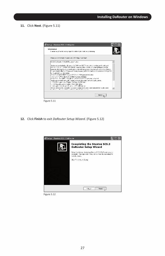
11. Click Next. (Figure 5.11)
12. Click Finish to exit DaRouter Setup Wizard. (Figure 5.12)
Figure 5.11
Figure 5.12
Installing DaRouter on Mac
5.2 Installing on OSX
Now we will briefly describe how to install DaRouter on your Macintosh® computer.
5.2.1 Installing DaRouter
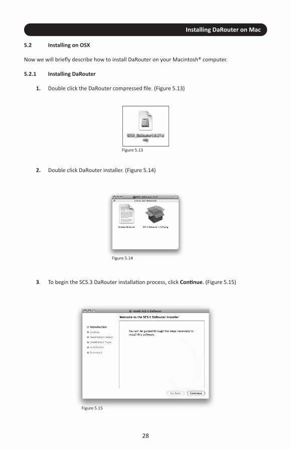
1. Double click the DaRouter compressed file. (Figure 5.13)
28
2. Double click DaRouter installer. (Figure 5.14)
3. To begin the SCS.3 DaRouter installation process, click Continue. (Figure 5.15)
Figure 5.13
Figure 5.14
Figure 5.15

Installing DaRouter on Mac
29
4. Read the License Agreement and click Continue. (Figure 5.16)
If the following message appears click Agree. (Figure 5.17)
Figure 5.17
5. Click Install. (Figure 5.18)
Figure 5.18
Figure 5.16

Installing DaRouter on Mac
30
Figure 5.19
6. The software was successfully installed. Click Close. (Figure 5.19)
To launch Stanton the SCS.3 DaRouter, double click the icon located in your desktop or go to yourApplications folder and double click the Stanton SCS.3 DaRouter icon.
Configuring DaRouter
The Preset Section (Figure 5.20)
31
Figure 5.20
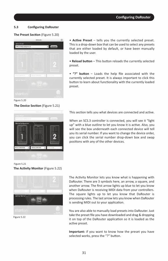
• Active Preset – tells you the currently selected preset. This is a drop-down box that can be used to select any presetsthat are either loaded by default, or have been manuallyloaded by the user.
• Reload button – This button reloads the currently selectedpreset.
• “?” button – Loads the help file associated with thecurrently selected preset. It is always important to click thisbutton to learn about functionality with the currently loadedpreset.
The Device Section (Figure 5.21)
Figure 5.21
This section tells you what devices are connected and active.
When an SCS.3 controller is connected, you will see it “lightup” with a blue outline to let you know it is active. Also, youwill see the box underneath each connected device will tellyou its serial number. If you want to change the device order,you can click the serial number drop-down box and swappositions with any of the other devices.
The Activity Monitor (Figure 5.22)
Figure 5.22
The Activity Monitor lets you know what is happening withDaRouter. There are 3 symbols here, an arrow, a square, andanother arrow. The first arrow lights up blue to let you knowwhen DaRouter is receiving MIDI data from your controllers.The square lights up to let you know that DaRouter isprocessing rules. The last arrow lets you know when DaRouteris sending MIDI out to your application.
You are also able to manually load presets into DaRouter. Justtake the preset file you have downloaded and drag & droppingit on top of the DaRouter application so it is loaded as theactive preset.
Important: if you want to know how the preset you haveselected works, press the “?” button.
5.3 Configuring DaRouter

Using the SC System 3 for generic MIDI Control
6. Using the SC System 3 for generic MIDI Control
In addition to the Virtual DJ LE specific operation, the SC System 3 can be used as a powerful MIDIcontroller solution for any MIDI compatible application by selecting a different preset. If you are notusing Virtual DJ LE, please check the Stanton website and forums to see if there is a specific DaRouterpreset available for your favorite application.
The SCS.3d and SCS.3m work slightly different in respect to how they can be used generically.The SCS.3m has standalone-preset functionality built into the hardware, whereas the SCS.3d alwaysrequires DaRouter to be running. Likewise, when all 3 components are going to be used togetherDaRouter must be running.
Now, let’s go over how to configure the SCS.3m and SCS.3d as standalone, and the SC System 3 as awhole for Generic MIDI Control.
6.1. SCS.3m Standalone Configuration
The SCS.3m works in three modes, Automatic mode for standard MIDI use cases, Application Feedbackmode for applications with MIDI output, and Flat mode for running DaRouter presets.In Automatic and Application Feedback modes, all the deck/mode switching is handled by the SCS.3mfor easy MIDI learning. In Automatic mode, the SCS.3m controls all of its own LEDs. In ApplicationFeedback mode, the SCS.3m processes MIDI output from your application to keep LEDs in syncbetween the application and one or more controllers. For more information, please visitwww.stantondj.com/SCS3m/MIDI/
When using the SCS.3m by itself, DaRouter does not need to be running. In the MIDI configurationdialog of the application that you are using, please select the SCS.3m instead of DaRouter.
Important: If you plan to use MIDI directly from the SCS.3m, do not run DaRouter.
6.1.1 Selecting MIDI Channel
The SCS.3m can be reconfigured to broadcast and receive on different MIDI channels to allow multipleSCS.3m units to be connected to the same computer without channel conflicts, or for use with othercontrollers with fixed MIDI channels. To change the MIDI channel on the SCS.3m follow the instructionsbelow:
1) Cover the entire top right slider with your fingers and press the lower right headphone button.2) The center section of the SCS.3m will light red to indicate that the unit is now ready to change its MIDI channel.3) You can change the MIDI channel by pressing any of the center buttons to select the channel. The top left button is MIDI channel 1 and the channels cascade from left to right so the top right button would be MIDI channel 2. Select any button to change the MIDI channel from 1-8 and the unit will update to broadcast and receive on that channel.
32

Selecting Built-in Presets
33
Button Preset # Button State Absolute Sliders Relative Sliders Slider Pattern
1 Preset 1 Trigger S3 – S11S1, S2 and S9, S10
(Master only) default
2 Preset 2 Trigger AllS9, S10
(Master only) default
3 Preset 3 Toggle AllS9, S10
(Master only) All bottom-top
4 Preset 4 Toggle S9 – S11 S1 – S8 n/a
5 Preset 5 Trigger All None All bottom-top
6 Preset 6 Trigger S9 – S11 S1 – S8 n/a
7 Preset 7 Toggle None All n/a
8 Preset 8 Trigger None All n/a
6.1.2 Selecting Built-in Presets
The SCS.3m comes with built-in intelligent firmware presets for different mapping configurations ofthe sliders and buttons. For instance, the default functionality of the SCS.3m shows sliders as boost/kill for “EQ mode”, but both the LED feedback and slider message output can be changed dependingon what your MIDI application accepts as an incoming message. To access the built-in firmware presetsfollow the instructions below:
1) Cover the entire top left slider and press the lower right headphone button.2) The center section of the SCS.3m will light red to indicate that built-in preset select mode is activated. The preset numbers start with the top left button and go from left to right, so for instance “Preset 2” is the top right button.3) You can select a built-in preset at this time to change the configuration of the SCS.3m sliders and buttons.4) Make sure that the unit is not in Application feedback mode if you are using it with an application that does not support MIDI output (most applications do not). If you are not seeing feedback on the sliders and buttons, toggle between Automatic and Application feedback by covering the top left slider and pressing the lower left headphone button.
Depending on your application, different presets will be desired. For example, if you are using AbletonLive all sliders with sweep feedback might be desired such as the configuration for preset 3. Below isa table of all the built-in presets and their functionality:
To choose the “right” preset, first review the table above to determine which type of interaction youneed. Below are definitions of the terms used in the table:
Button States
Trigger – Trigger means the LED for the button will only illuminate when a finger is placed on thebutton. Good for triggering samples.Toggle – Toggle means the LED will change from blue to red when a finger is pressed and then willchange back to blue when pressed again. This is good for functions that turn On and Off.
Advance Control of Built-in Presets
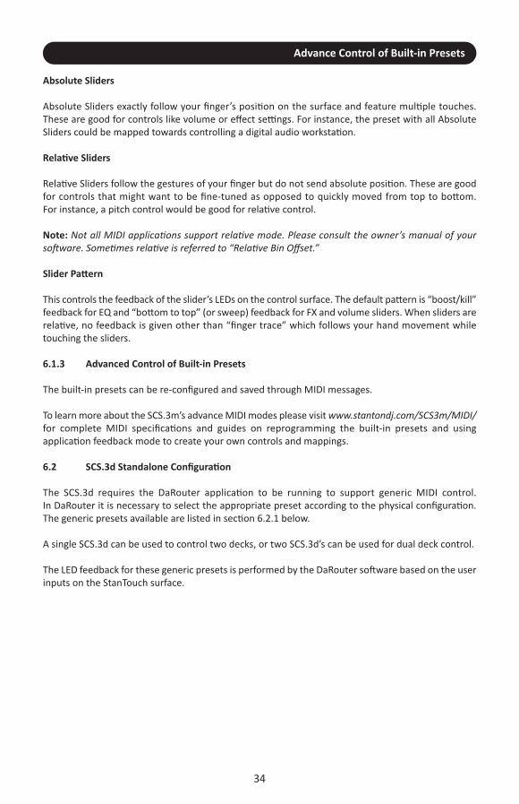
Absolute Sliders
Absolute Sliders exactly follow your finger’s position on the surface and feature multiple touches.These are good for controls like volume or effect settings. For instance, the preset with all AbsoluteSliders could be mapped towards controlling a digital audio workstation.
Relative Sliders
Relative Sliders follow the gestures of your finger but do not send absolute position. These are goodfor controls that might want to be fine-tuned as opposed to quickly moved from top to bottom. For instance, a pitch control would be good for relative control.
Note: Not all MIDI applications support relative mode. Please consult the owner’s manual of yoursoftware. Sometimes relative is referred to “Relative Bin Offset.”
Slider Pattern
This controls the feedback of the slider’s LEDs on the control surface. The default pattern is “boost/kill”feedback for EQ and “bottom to top” (or sweep) feedback for FX and volume sliders. When sliders arerelative, no feedback is given other than “finger trace” which follows your hand movement whiletouching the sliders.
6.1.3 Advanced Control of Built-in Presets
The built-in presets can be re-configured and saved through MIDI messages.
To learn more about the SCS.3m’s advance MIDI modes please visit www.stantondj.com/SCS3m/MIDI/for complete MIDI specifications and guides on reprogramming the built-in presets and usingapplication feedback mode to create your own controls and mappings.
6.2 SCS.3d Standalone Configuration
The SCS.3d requires the DaRouter application to be running to support generic MIDI control.In DaRouter it is necessary to select the appropriate preset according to the physical configuration.The generic presets available are listed in section 6.2.1 below.
A single SCS.3d can be used to control two decks, or two SCS.3d’s can be used for dual deck control.
The LED feedback for these generic presets is performed by the DaRouter software based on the userinputs on the StanTouch surface.
34
Selecting Presets
6.2.1 Selecting Presets
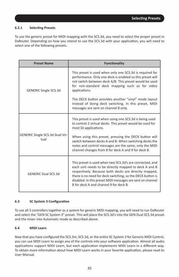
To use the generic preset for MIDI mapping with the SCS.3d, you need to select the proper preset inDaRouter. Depending on how you intend to use the SCS.3d with your application, you will need toselect one of the following presets.
35
Preset Name Functionality
GENERIC Single SCS.3d
This preset is used when only one SCS.3d is required forperformance. Only one deck is enabled so this preset willnot switch between deck A/B. This preset would be usedfor non-standard deck mapping such as for videoapplications.
The DECK button provides another “vinyl” mode layoutinstead of doing deck switching. In this preset, MIDImessages are sent on channel 8 only.
GENERIC Single SCS.3d Dual Vir-tual
This preset is used when using one SCS.3d is being usedto control 2 virtual decks. This preset would be used formost DJ applications.
When using this preset, pressing the DECK button willswitch between decks A and B. When switching decks thenotes and control messages are the same, only the MIDIchannel changes from 8 for deck A and 9 for deck B.
GENERIC Dual SCS.3d
This preset is used when two SCS.3d’s are connected, andeach unit needs to be directly mapped to deck A and Brespectively. Because both decks are directly mapped,there is no need for deck switching, so the DECK button isdisabled. In this preset MIDI messages are sent on channel8 for deck A and channel 9 for deck B.
6.3 SC System 3 Configuration
To use all 3 controllers together as a system for generic MIDI mapping, you will need to run DaRouterand select the “GEN SC System 3” preset. This will place the SCS.3d’s into the GEN Dual SCS.3d presetand the mixer into Automatic mode as described above.
6.4 MIDI Learn
Now that you have configured the SCS.3m, SCS.3d, or the entire SC System 3 for Generic MIDI Control,you can use MIDI Learn to assign any of the controls into your software application. Almost all audioapplications support MIDI Learn, but each application implements MIDI Learn in a different way. To obtain more information about how MIDI Learn works in your favorite application, please read itsUser Manual.

Troubleshooting
7. Troubleshooting
1) When I connect the SCS.3m to my computer, it seems to work normally, but nothing connected to its USB ports (like the SCS.3d controllers and/or other external devices) works properly.
This usually happens when the SCS.3m is not getting power. Verify that your SCS.3m is plugged into mains power via the included adapter. If it is, verify that the outlet you are plugged into is working properly.
2) I have my SCS.3m attached to my computer via a USB hub and cannot get it to work.
It’s never a good idea to connect one USB hub into another hub. Please make sure you plug the SCS.3m (which contains its own powered USB hub) directly into a port on your computer.
3) It is very difficult to turn the knobs on the back of the units (when removing the rear cover).
Especially when SCS.3 controllers are new, those knobs can be hard to turn with just your fingers. On the top of each knob is a slot in which the edge of a coin can be placed to make turning them easier.
4) The SCS.3 controllers work, but sometimes they are sluggish and do not respond quickly to my touch.
This can happen when your hand or the controllers get moist. If this is the case (like if you’re working in a hot club and sweating), dry off your hands and/or the SCS.3 controllers as much as possible.
5) The SCS.3 controllers do not work with Virtual DJ LE as described or at all?
Please confirm the connection between SCS.3 and Virtual DJ by opening the CONFIG menu within Virtual DJ. and check the MAPPERS section. This will tell you if your devices are connected. As well, some computers put out very low USB bus power. If this is the case, it may be necessary to purchase a powered USB hub to connect your SCS.3 system to your computer.
6) When I try to connect SCS.3d to the SCS.3m, it is not recognized and/or the LEDs on the unit light in an irregular pattern.
Check that the USB cable is securely connected to both the computer and SCS.3m, and verify that the SCS.3m is plugged into mains power. This can sometimes also be caused by an underpowered USB port, so try plugging the SCS.3m into a different port on your computer. Finally, it’s not a good idea to plug the SCS.3 pack into any hub (since the SCS.3m is a hub on its own).
7) I do not have an Internet connection and I am unable to download any software associated with the SC System 3 (new presets, etc).
If you are unable to connect to the Internet, Stanton will provide you with the needed software and documentation free of charge. Call Stanton Support at XXXXXXXXXXXXXXXX and it will be shipped out to you.
8) My problem is not covered here.
Please go to www.stantondj.com/scsystem3 for more in depth troubleshooting information.
36
Specifications
8. Specifications
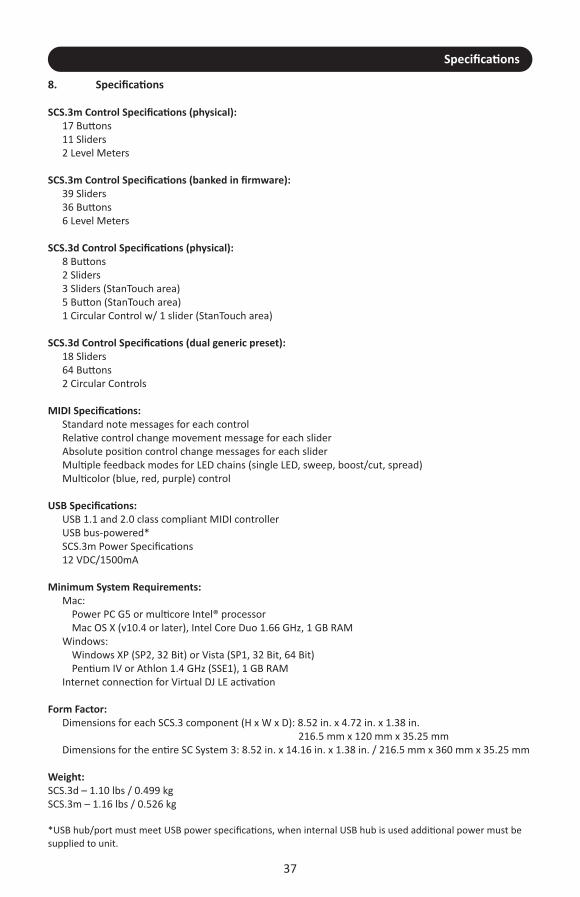
SCS.3m Control Specifications (physical): 17 Buttons 11 Sliders 2 Level Meters
SCS.3m Control Specifications (banked in firmware): 39 Sliders 36 Buttons 6 Level Meters
SCS.3d Control Specifications (physical): 8 Buttons 2 Sliders 3 Sliders (StanTouch area) 5 Button (StanTouch area) 1 Circular Control w/ 1 slider (StanTouch area)
SCS.3d Control Specifications (dual generic preset): 18 Sliders 64 Buttons 2 Circular Controls
MIDI Specifications: Standard note messages for each control Relative control change movement message for each slider Absolute position control change messages for each slider Multiple feedback modes for LED chains (single LED, sweep, boost/cut, spread) Multicolor (blue, red, purple) control
USB Specifications: USB 1.1 and 2.0 class compliant MIDI controller USB bus-powered* SCS.3m Power Specifications 12 VDC/1500mA
Minimum System Requirements: Mac: Power PC G5 or multicore Intel® processor Mac OS X (v10.4 or later), Intel Core Duo 1.66 GHz, 1 GB RAM Windows: Windows XP (SP2, 32 Bit) or Vista (SP1, 32 Bit, 64 Bit) Pentium IV or Athlon 1.4 GHz (SSE1), 1 GB RAM Internet connection for Virtual DJ LE activation
Form Factor: Dimensions for each SCS.3 component (H x W x D): 8.52 in. x 4.72 in. x 1.38 in.
216.5 mm x 120 mm x 35.25 mm Dimensions for the entire SC System 3: 8.52 in. x 14.16 in. x 1.38 in. / 216.5 mm x 360 mm x 35.25 mm
Weight: SCS.3d – 1.10 lbs / 0.499 kgSCS.3m – 1.16 lbs / 0.526 kg
*USB hub/port must meet USB power specifications, when internal USB hub is used additional power must besupplied to unit.
37

WarrantyWARRANTY
Thank you for choosing one of Gibson Pro Audio’s brands (Stanton, KRK, or Cerwin Vega!).Your satisfaction is extremely important to us. We proudly stand behind the quality of our work andappreciate that you put your trust in us. Registering your merchandise will help us guarantee that youare kept up to date on our latest advances.To Register Merchandise Purchased from an Authorized Gibson Pro Audio Dealer in the U.S.: Please go to: http://www.gibson.com and register online. Or you may send your warranty card to:Gibson Customer Service309 Plus Park Blvd.Nashville, TN 37217
If you have any questions you may contact customer service at: 1-800-4GIBSON (1-800-444-2766)e-mail: [email protected] MERCHANDISE PURCHASED FROM AN AUTHORIZED GIBSON PRO AUDIO DISTRIBUTOR OUTSIDEOF THE US, PLEASE CONTACT THE DISTRIBUTOR FROM WHOM YOU PURCHASED YOUR MERCHANDISEFOR TO REGISTER YOUR WARRANTY AND FOR HANDLING AND RESOLUTION OF ALL WARRANTY-RELATED ISSUES.
Gibson Pro Audio WarrantyIf at any time your Gibson Pro Audio product (which includes Stanton, KRK, or Cerwin Vega! brands)malfunctions as a result of faulty materials or workmanship, Gibson Pro Audio or one of Gibson ProAudio’s Authorized Service Centers in the US will repair the defect(s) or replace the merchandise, asit deems appropriate at its sole discretion.Warranty Period (from date of Purchase as listed on the Bill of Sale): StantonOne (1) year for all Stanton products.
KRKThree (3) years from all studio monitors. One (1) year all headphones, computer audio devices, including room correction devices.
Cerwin Vega!Five (5) years for all passive speaker systems. Three (3) years for all active speaker systems.One (1) year for mixers.
38
WarrantyGibson will warrant all replacement parts and repairs for ninety (90) days from the date of original shipment.
In the unlikely event that your merchandise is destroyed, lost or damaged beyond repair while in the possession of Gibson or oneof Gibson Pro Audio’s Authorized Service Centers for repair, Gibson will replace that merchandise with one of the same or mostsimilar style of a value not in excess of the original purchase price of your merchandise. Any insurance covering the merchandise,including but not limited to collector's value insurance, must be carried by owner at owner's expense.For the fastest and safest merchandise return, please use the original shipping carton and packaging materials. Gibson cannot beresponsible for any damages incurred during the shipping process due to poor or inadequate packing. THIS WARRANTY IS EXTENDED TO THE ORIGINAL RETAIL PURCHASER ONLY AND MAY NOT BE TRANSFERRED OR ASSIGNED TOSUBSEQUENT OWNERS. IN ORDER TO VALIDATE YOUR WARRANTY, AND AS A CONDITION PRECEDENT TO WARRANTY COVERAGEHEREUNDER, YOU MUST REGISTER YOUR WARRANTY WITHIN FIFTEEN (15) DAYS FOLLOWING THE ORIGINAL DATE OFPURCHASE.YOUR PROOF OF PURCHASE OR SALES RECEIPT MUST ACCOMPANY ALL REQUESTS FOR WARRANTY COVERAGE.
This warranty is subject to the following limitations:
THIS WARRANTY DOES NOT COVER 1. Any merchandise that has been altered or modified in any way or upon which the serial number has been tampered with oraltered.2. Any merchandise whose warranty card has been altered or upon which false information has been given. 3. Any merchandise that has been damaged due to misuse, negligence, or improper operation. 4. Any merchandise that has been damaged by accident, flood, fire, lightening, or other acts of God. 5. Shipping damage of any kind.6. Any merchandise that has been subjected to extremes of humidity or temperature.7. Any merchandise that has been purchased from an unauthorized dealer, or upon which unauthorized repair or service has beenperformed.
GIBSON MAKES NO OTHER EXPRESS WARRANTY OF ANY KIND WHATSOEVER. ALL IMPLIED WARRANTIES, INCLUDING WARRANTIESOF MERCHANTABILITY AND FITNESS FOR A PARTICULAR PURPOSE, EXCEEDING THE SPECIFIC PROVISIONS OF THIS WARRANTY AREHEREBY DISCLAIMED AND EXCLUDED FROM THIS WARRANTY. SOME STATES AND/OR COUNTRIES DO NOT ALLOW THE EXCLUSIONOR LIMITATION OF IMPLIED WARRANTIES SO THAT THE ABOVE MAY NOT APPLY TO YOU. GIBSON SHALL NOT BE LIABLE FOR ANY SPECIAL, INDIRECT CONSEQUENTIAL, INCIDENTAL OR OTHER SIMILAR DAMAGES SUFFEREDBY THE PURCHASER OR ANY THIRD PARTY, INCLUDING WITHOUT LIMITATION, DAMAGES FOR LOSS OF PROFITS OR BUSINESS ORDAMAGES RESULTING FROM USE OR PERFORMANCE OF THE MERCHANDISE, WHETHER IN CONTRACT OR IN TORT, EVEN IF GIBSONOR ITS AUTHORIZED REPRESENTATIVE HAS BEEN ADVISED OF THE POSSIBILITY OF SUCH DAMAGES, AND GIBSON SHALL NOT BELIABLE FOR ANY EXPENSES, CLAIMS, OR SUITS ARISING OUT OF OR RELATING TO ANY OF THE FOREGOING. FOR MERCHANDISE PURCHASED FROM AN AUTHORIZED GIBSON PRO AUDIO DISTRIBUTOR OUTSIDE OF THE US, PLEASE CONTACTTHE DISTRIBUTOR FROM WHOM YOU PURCHASED YOUR MERCHANDISE FOR THE HANDLING AND RESOLUTION OF ALL WARRANTYISSUES. FOR THESE PURCHASES, THE ABOVE-DESCRIBED WARRANTY IS NOT APPLICABLE.
How to Obtain Warranty Service
Warranty Service outside the United States:To initiate a warranty repair, please contact the Authorized Gibson Pro Audio distributor from whom you purchased yourmerchandise, and follow the distributor’s return/warranty policy.
Warranty Service for Merchandise Purchased from an Authorized Gibson Pro Audio Dealer in the U.S:In the event of malfunction of your Gibson Pro Audio merchandise, the Dealer or Owner must call Customer Service @ 1-800-4GIBSON (1-800-444-2766) and obtain a Return Authorization number from the customer service agent. No merchandise may bereturned to Gibson without such prior Return Authorization, and the Return Authorization number must be written on the outsideof the shipping package. The Customer Service agent will provide the address and additional shipping instructions. Owner mustship the merchandise, freight, and insurance pre-paid to the address provided by the customer service representative. OnlyAuthorized Gibson Pro Audio Service Centers may perform warranty service and any service performed by unauthorized personswill void this warranty. Gibson disclaims liability for defects or damage caused by services performed by unauthorized persons ornon-warranty service not performed by Gibson or an Authorized Gibson Pro Audio Service Center.
39

Notes
.............................................................................................................
.............................................................................................................
.............................................................................................................
.............................................................................................................
.............................................................................................................
.............................................................................................................
.............................................................................................................
.............................................................................................................
.............................................................................................................
.............................................................................................................
.............................................................................................................
.............................................................................................................
.............................................................................................................
.............................................................................................................
.............................................................................................................
.............................................................................................................
.............................................................................................................
.............................................................................................................
.............................................................................................................
.............................................................................................................
.............................................................................................................
.............................................................................................................
.............................................................................................................
.............................................................................................................
.............................................................................................................
40

Copyright © 2012 Stanton Magnetics, Inc.SCS, SC System, DaScratch, DaRouter, and StanTouch are registered trademarks of the Stanton Group.
Virtual DJ is a registered trademark of Atomix.All other trademarks are property of their respective owners, who are in no way affiliated with Stanton DJ or
SC System products. All information included in the User Manual is subject to change without notice.(+1.877.578. 6866)
L****************