Embed Size (px)
Citation preview
Safety Introduction
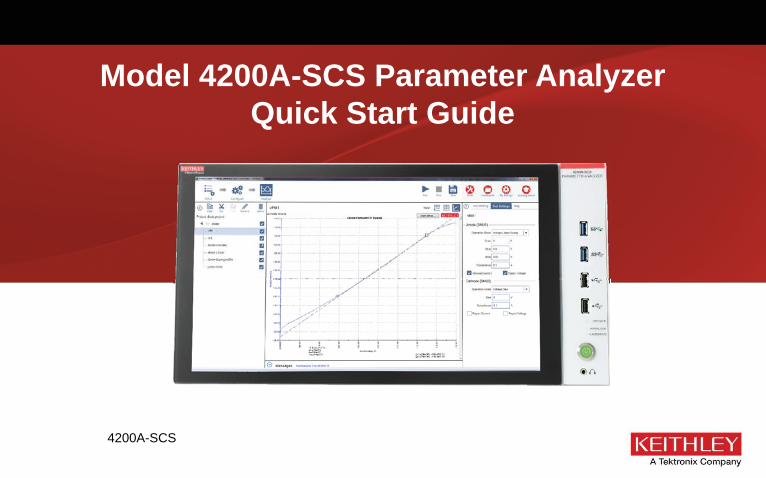
Model 4200A-SCS Parameter AnalyzerQuick Start Guide
4200A-SCS

Safety Introduction
Safety precautionsThe following safety precautions should be observed before using this product and any associated instrumentation. Although some instruments and accessories would normally be used with nonhazardous voltages, there are situations where hazardous conditions may be present.
This product is intended for use by qualifi ed personnel who recognize shock hazards and are familiar with the safety precautions required to avoid possible injury. Read and follow all installation, operation, and maintenance information carefully before using the product. Refer to the user documentation for complete product specifi cations.
If the product is used in a manner not specifi ed, the protection provided by the product warranty may be impaired.
The types of product users are:
Responsible body is the individual or group responsible for the use and maintenance of equipment, for ensuring that the equipment is operated within its specifi cations and operating limits, and for ensuring that operators are adequately trained.
Operators use the product for its intended function. They must be trained in electrical safety procedures and proper use of the instrument. They must be protected from electric shock and contact with hazardous live circuits.
Maintenance personnel perform routine procedures on the product to keep it operating properly, for example, setting the line voltage or replacing consumable materials. Maintenance procedures are described in the user documentation. The procedures explicitly state if the operator may perform them. Otherwise, they should be performed only by service personnel.
Service personnel are trained to work on live circuits, perform safe installations, and repair products. Only properly trained service personnel may perform installation and service procedures.
Keithley Instruments products are designed for use with electrical signals that are measurement, control, and data I/O connections, with low transient overvoltages, and must not be directly connected to mains voltage or to voltage sources with high transient
overvoltages. Measurement Category II (as referenced in IEC 60664) connections require protection for high transient overvoltages often associated with local AC mains connections. Certain Keithley measuring instruments may be connected to mains. These instruments will be marked as category II or higher.
Unless explicitly allowed in the specifi cations, operating manual, and instrument labels, do not connect any instrument to mains.
Exercise extreme caution when a shock hazard is present. Lethal voltage may be present on cable connector jacks or test fi xtures. The American National Standards Institute (ANSI) states that a shock hazard exists when voltage levels greater than 30 V RMS, 42.4 V peak, or 60 VDC are present. A good safety practice is to expect that hazardous voltage is present in any unknown circuit before measuring.
Operators of this product must be protected from electric shock at all times. The responsible body must ensure that operators are prevented access and/or insulated from every connection point. In some cases, connections must be exposed to potential human contact. Product operators in these circumstances must be trained to protect themselves from the risk of electric shock. If the circuit is capable of operating at or above 1000 V, no conductive part of the circuit may be exposed.
Do not connect switching cards directly to unlimited power circuits. They are intended to be used with impedance-limited sources. NEVER connect switching cards directly to AC mains. When connecting sources to switching cards, install protective devices to limit fault current and voltage to the card.
Before operating an instrument, ensure that the line cord is connected to a properly-grounded power receptacle. Inspect the connecting cables, test leads, and jumpers for possible wear, cracks, or breaks before each use.
When installing equipment where access to the main power cord is restricted, such as rack mounting, a separate main input power disconnect device must be provided in close proximity to the equipment and within easy reach of the operator.
For maximum safety, do not touch the product, test cables, or any other instruments while power is applied to the circuit under test. ALWAYS remove power from the entire test system and discharge any capacitors before: connecting or disconnecting cables or jumpers, installing or removing switching cards, or making internal changes, such as installing or removing jumpers.
Safety Introduction
The WARNING heading in the user documentation explains dangers that might result in personal injury or death. Always read the associated information very carefully before performing the indicated procedure.
The CAUTION heading in the user documentation explains hazards that could damage the instrument. Such damage may invalidate the warranty.
Instrumentation and accessories shall not be connected to humans.
Before performing any maintenance, disconnect the line cord and all test cables.
To maintain protection from electric shock and fi re, replacement components in mains circuits — including the power transformer, test leads, and input jacks — must be purchased from Keithley Instruments. Standard fuses with applicable national safety approvals may be used if the rating and type are the same. The detachable mains power cord provided with the instrument may only be replaced with a similarly rated power cord. Other components that are not safety-related may be purchased from other suppliers as long as they are equivalent to the original component (note that selected parts should be purchased only through Keithley Instruments to maintain accuracy and functionality of the product). If you are unsure about the applicability of a replacement component, call a Keithley Instruments offi ce for information.
Unless otherwise noted in product-specifi c literature, Keithley instruments are designed to operate indoors only, in the following environment: Altitude at or below 2,000 m (6,562 ft); temperature 0 °C to 50 °C (32 °F to 122 °F) ; and pollution degree 1 or 2.
To clean an instrument, use a damp cloth or mild, water-based cleaner. Clean the exterior of the instrument only. Do not apply cleaner directly to the instrument or allow liquids to enter or spill on the instrument. Products that consist of a circuit board with no case or chassis (e.g., a data acquisition board for installation into a computer) should never require cleaning if handled according to instructions. If the board becomes contaminated and operation is affected, the board should be returned to the factory for proper cleaning/servicing.
Safety precaution revision as of March 2016.
Do not touch any object that could provide a current path to the common side of the circuit under test or power line (earth) ground. Always make measurements with dry hands while standing on a dry, insulated surface capable of withstanding the voltage being measured.
When fuses are used in a product, replace with the same type and rating for continued protection against fi re hazard.
For safety, instruments and accessories must be used in accordance with the operating instructions. If the instruments or accessories are used in a manner not specifi ed in the operating instructions, the protection provided by the equipment may be impaired.
Do not exceed the maximum signal levels of the instruments and accessories. Maximum signal levels are defi ned in the specifi cations and operating information and shown on the instrument panels, test fi xture panels, and switching cards.
Chassis connections must only be used as shield connections for measuring circuits, NOT as protective earth (safety ground) connections.
If you are using a test fi xture, keep the lid closed while power is applied to the device under test. Safe operation requires the use of a lid interlock.
If a screw is present, connect it to protective earth (safety ground) using the wire recommended in the user documentation.
The symbol on an instrument means caution, risk of danger. The user must refer to the operating instructions located in the user documentation in all cases where the symbol is marked on the instrument.
The symbol on an instrument means caution, risk of electric shock. Use standard safety precautions to avoid personal contact with these voltages.
The symbol on an instrument shows that the surface may be hot. Avoid personal contact to prevent burns.
The symbol indicates a connection terminal to the equipment frame.
If this symbol is on a product, it indicates that mercury is present in the display lamp. Please note that the lamp must be properly disposed of according to federal, state, and local laws.
Safety Introduction Connect FAQsNext stepsSafety

Power and environmental specifi cations
For indoor use only.
Power Supply 100 VAC to 240 VAC, 50 Hz to 60 HzMaximum VA 1000 VAOperating altitude Maximum 2000 m (6562 feet) above
sea levelOperating temperature
10 °C to 40 °C (50 °F to 104 °F), 5 % to 80 % relative humidity, non-condensing
Storage temperature -15 °C to 60 °C (5 °F to 140 °F), 5 % to 90 % relative humidity, non-condensing
Carefully consider and confi gure the appropriate output-off state, source levels, and compliance levels before connecting the instrument to a device that can deliver energy. Failure to consider the output-off state, source levels, and compliance levels may result in damage to the instrument or to the device under test.
Safety Introduction
USB fl ash drive contents
The USB fl ash drive that is included with your instrument contains installation fi les for Clarius+. These can only be installed on the 4200A-SCS Parameter Analyzer.
For complete documentation for the 4200-SCS, see the 4200A-SCS Learning Center .
For additional support information, see http://www.tek.com/keithley.
Introduction
The easy-to-use Model 4200A-SCS Parameter Analyzer performs lab grade DC and pulse device characterization, real-time plotting, and analysis with high precision and sub-femtoamp resolution. The 4200A-SCS offers the most advanced capabilities available in a fully integrated characterization system, including a complete, embedded computer with a Microsoft Windows operating system and mass storage. When running a test sequence, you can view results and plots for completed tests while the sequence is still running so you can begin analyzing results sooner.
Safety Introduction Connect FAQsNext stepsIntroduction

Unpack and inspect the instrument
To unpack and inspect the instrument:
1. Inspect the box for damage.
2. Open the top of the box.
3. Remove the documentation, standard accessories, USB fl ash drive, and optional accessories (such as rack-mount hardware).
4. Remove the packaging insert.
5. Remove the 4200A-SCS.
6. Inspect the instrument for any obvious signs of physical damage. Report any damage to the shipping agent immediately.
The 4200A-SCS is heavy and requires a two person lift since it weighs approximately 27 kilograms (60 pounds). Do not lift the 4200A-SCS alone and do not lift the 4200A-SCS using the front bezel. Lifting the instrument by the front bezel can cause instrument damage.

Safety Introduction
You should have received the 4200A-SCS Parameter Analyzer with:
• Keyboard with integrated mouse
• Clarius+ software USB fl ash drive
• Power line cord
• 236-ILC-3 safety interlock cable
• 4200A-SCS Quick Start Guide (not shown; this document)
Refer to the packing list for additional items that might have shipped with your instrument.
Safety Introduction Connect FAQsNext stepsIntroduction

• Cover the device under test (DUT) to protect the operator from fl ying debris in the event of a system or DUT failure.
• Double-insulate all electrical connections that an operator can touch. Double insulation ensures the operator is still protected even if one insulation layer fails. Refer to IEC 61010-1 for specifi c requirements.
• Make sure all connections are behind a locked cabinet door or other barrier. This protects the system operator from accidentally removing a connection by hand and exposing hazardous voltages. Use high-reliability fail-safe interlock switches to disconnect power sources when a test fi xture cover is opened.
• Where possible, use automatic handlers so operators are not required to access the DUT or other potentially hazardous areas.
• Provide training to all users of the system so they understand all potential hazards and know how to protect themselves from injury.
• In many systems, during power up, the outputs may be in an unknown state until they are properly initialized. Make sure the design can tolerate this situation without causing operator injury or hardware damage.
Connect the instrumentImportant test system safety information
This system contains instruments that can produce hazardous voltages. It is the responsibility of the test system installer, maintenance personnel, and service personnel to make sure the system is safe during use and is operating properly. You must also realize that in many test systems a single fault, such as a software error, may output hazardous signal levels even when the system indicates that there is no hazard present. It is important that you consider the following factors in your system design and use:
• The international safety standard IEC 61010-1 defi nes voltages as hazardous if they exceed 30 V RMS and 42.4 V peak, or 60 VDC for equipment rated for dry locations. Keithley Instruments products are only rated for dry locations.
• Read and comply with the specifi cations of all instruments in the system. The overall allowed signal levels may be constrained by the lowest rated instrument in the system. For example, if you are using a 500 V power supply with a 300 VDC rated switch, the maximum allowed voltage in the system is 300 VDC.
• Make sure any test fi xture connected to the system protects the operator from contact with hazardous voltages, hot surfaces, and sharp objects. Use shields, barriers, insulation, and safety interlocks to accomplish this.

Safety Introduction
Install the instrumentThe 4200A-SCS can be used on a bench or in a rack. Please see the instructions that came with your rack-mount kit if you are installing the 4200A-SCS in a rack.
Wiring the interlockIf you need voltages greater than ±40 V for testing, you must add an interlock switch to the fi xture. This ensures that hazardous voltages are not present when the exterior enclosure of the fi xture is open. It also enables the 4200A-SCS to output higher voltages when the exterior enclosure of the fi xture is closed.
When the safety interlock signal is asserted (the switch is closed and the signal is connected to +12 V), all the voltage ranges of the SMUs are functional. When the safety interlock signal is not asserted (the switch is open), the 200 V range on the SMUs is disabled, limiting the nominal output to ±40 V.
To keep users safe, always read and follow all safety warnings provided with each of the instruments in your system.
If you need voltages greater than ±40 V, you must also connect the exterior of the test fi xture enclosure to protective earth (safety ground). Take care to ensure that the wiring (FORCE, GUARD, and SENSE) in the fi xture does not electrically contact the exterior enclosure.
The 4200A-SCS is provided with an interlock circuit that must be positively activated for the high-voltage output to be enabled. The interlock facilitates safe operation of the equipment in a test system. Bypassing the interlock could expose the operator to hazardous voltage that could result in personal injury or death. Asserting the interlock allows the SMU and preamplifi er terminals to become hazardous, exposing the user to possible electrical shock that could result in personal injury or death. SMU and preamplifi er terminals should be considered hazardous even if the outputs are programmed to be low voltage. Precautions must be taken to prevent a shock hazard by surrounding the test device and any unprotected leads (wiring) with double insulation for 250 V, Category 0.
Safety Introduction FAQsNext stepsConnect

There are low-voltage and high-voltage test fi xtures for the 4200A-SCS. Low-voltage fi xtures, such as the Keithley Instruments 8101-PIV, are intended for applications that are less than ±40 V. For these applications, an interlock is not needed.
High-voltage test fi xtures, such as the Keithley Instruments LR:8028, can be used with applications that are greater than ±40 V. The test fi xture has a safety interlock switch connected to its lid. When the lid is closed, the interlock circuit is closed (asserted), and SMU ±200 V ranges are enabled.
Conversely, the interlock circuit is open (de-asserted) when the lid is open, and the SMU ±200 V ranges are disabled. High-voltage test fi xtures require extra precaution to ensure there are no shock hazards.
For correct operation with the 4200A-SCS, the test fi xture should have a normally open switch that is used for the interlock. An open interlock condition occurs when the switch is open.
The 4200A-SCS functions on all current ranges and up to ±40 V without asserting the interlock. When the interlock is not asserted, the maximum voltage on the SMU and preamplifi er terminals is not hazardous.

Safety Introduction
To connect the interlock cable:
1. Connect one end of the supplied interlock cable (part number 236-ILC-3) to the rear panel of the 4200A-SCS. The location of the rear panel interlock connector is shown in the following graphic.
2. Connect the other end of the connector to the test fi xture.
Test connectionsIf you are testing discrete devices, you need a test fi xture that is equipped with 3-lug triaxial connectors. The 8101-PIV test fi xture, which can be purchased from Keithley Instruments, allows the 4200A-SCS to be connected to a discrete device.
For connections to a probe station for wafer testing, see the 4200A-SCS Learning Center .
Safety Introduction FAQsNext stepsConnect
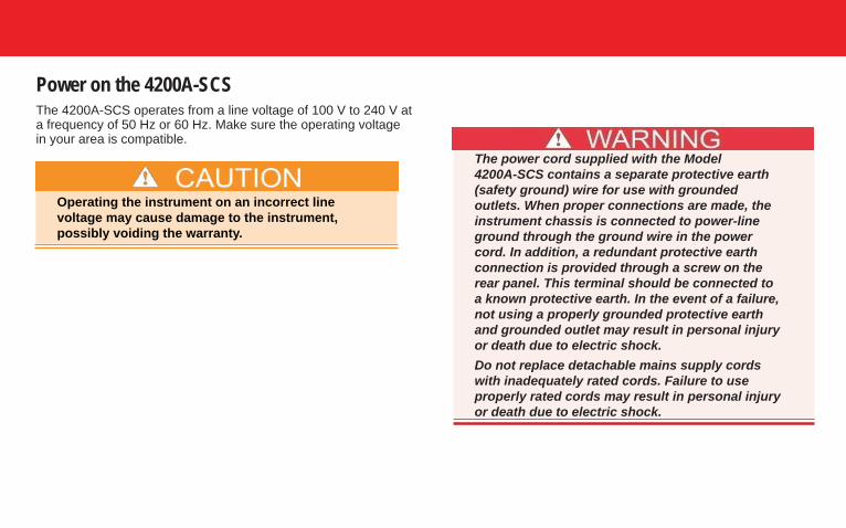
Power on the 4200A-SCSThe 4200A-SCS operates from a line voltage of 100 V to 240 V at a frequency of 50 Hz or 60 Hz. Make sure the operating voltage in your area is compatible.
Operating the instrument on an incorrect line voltage may cause damage to the instrument, possibly voiding the warranty.
The power cord supplied with the Model 4200A-SCS contains a separate protective earth (safety ground) wire for use with grounded outlets. When proper connections are made, the instrument chassis is connected to power-line ground through the ground wire in the power cord. In addition, a redundant protective earth connection is provided through a screw on the rear panel. This terminal should be connected to a known protective earth. In the event of a failure, not using a properly grounded protective earth and grounded outlet may result in personal injury or death due to electric shock. Do not replace detachable mains supply cords with inadequately rated cords. Failure to use properly rated cords may result in personal injury or death due to electric shock.
Safety Introduction
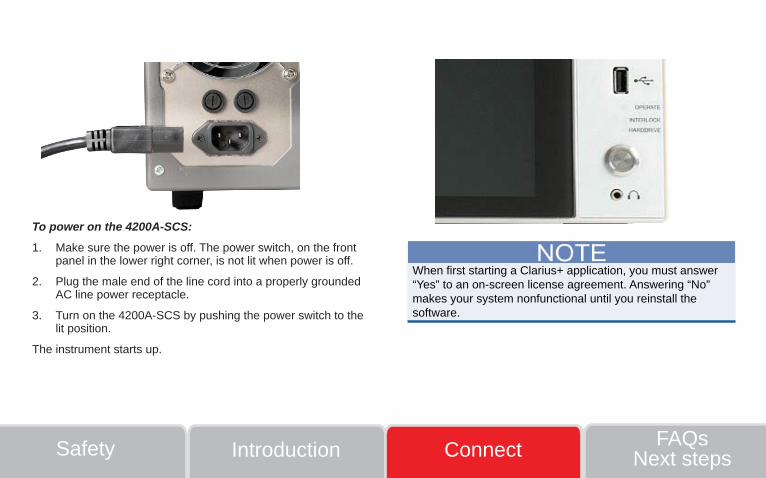
To power on the 4200A-SCS:
1. Make sure the power is off. The power switch, on the front panel in the lower right corner, is not lit when power is off.
2. Plug the male end of the line cord into a properly grounded AC line power receptacle.
3. Turn on the 4200A-SCS by pushing the power switch to the lit position.
The instrument starts up.
When fi rst starting a Clarius+ application, you must answer “Yes” to an on-screen license agreement. Answering “No” makes your system nonfunctional until you reinstall the software.
Safety Introduction FAQsNext stepsConnect
The default powerline frequency is set to 60 Hz. If the setting is wrong, the 4200A-SCS cannot properly reject powerline measurement noise.
To change the powerline frequency:
1. Close Clarius.
2. Run KCon.
3. Select KI 4200A SCS in the Confi guration Navigator. The left pane is the Confi guration Navigator.
4. Change the Powerline Frequency as needed.
5. Select Save .
Change powerline frequency

Safety Introduction FAQsNext stepsConnect
FAQs
How should I clean the front-panel display?
If you need to clean the front-panel LCD touchscreen display, use a soft dry cloth. If necessary, use a cloth dampened with an ammonia-free glass cleaner. Do not spray cleaning fl uids onto the display. Additionally, it is strongly recommended that you use only fi ngers on the touchscreen. Do not use sharp objects, such as a pen or pencil, to touch the touchscreen.
My data looks odd or is wrong. What should I do?
Verify the connections from the instrument to the test fi xture. Also check the connections from the DUT to the test fi xture socket.
I cannot unplug the mini-triaxial cable (4200A-MTRX) from the SMU. What should I do?
The mini-triaxial connector is a locking connector. To remove it, pull the knurled part of the connector back.
A confi guration error has been detected and I cannot launch Clarius. What should I do?
This occurs when the physical confi guration does not match the KCon defi ned confi guration or when there are communication problems between instruments and the 4200A-SCS.
To verify system confi guration:
1. Run KCon.
2. Select Validate Confi guration.
This can also occur if the preamplifi er or RPM is removed or reconnected.
To update the system confi guration:
1. Run KCon.
2. Select Upgrade Preamp, RPM, and CVIV Confi guration.
Note that preamplifi ers are SMU specifi c. For example, a preamplifi er that is confi gured for SMU1 cannot be connected to SMU2.
Safety Introduction
Next steps
See the 4200A-SCS Learning Center , which is preinstalled on your system. To access the Learning Center, click Help in the Clarius menu, press F1 while using Clarius, or select the desktop icon.
The 4200A-SCS Learning Center includes the following:
• Instructional videos and text: Contains basic and detailedinformation about using the system that will help you with theinstrument.
• 4200A-SCS User Manual: Contains basic information aboutusing the system, plus application-based examples that willhelp familiarize you with the instrument.
• 4200A-SCS Reference Manual: Provides detailedinformation about all features of the instrument.
• Application notes: Detailed applications that demonstratespecifi c applications.
• Data sheets: Technical data regarding the 4200A-SCS andrelated accessories.
See: www.tek.com/keithley for support and additional information about the instrument.
Safety Introduction Connect FAQsNext steps

Contact Information: Australia* 1 800 709 465Austria 00800 2255 4835
Balkans, Israel, South Africa and other ISE Countries +41 52 675 3777Belgium* 00800 2255 4835
Brazil +55 (11) 3759 7627Canada 1 800 833 9200
Central East Europe / Baltics +41 52 675 3777Central Europe / Greece +41 52 675 3777
Denmark +45 80 88 1401Finland +41 52 675 3777France* 00800 2255 4835
Germany* 00800 2255 4835Hong Kong 400 820 5835
India 000 800 650 1835Indonesia 007 803 601 5249
Italy 00800 2255 4835Japan 81 (3) 6714 3010
Luxembourg +41 52 675 3777Malaysia 1 800 22 55835
Mexico, Central/South America and Caribbean 52 (55) 56 04 50 90Middle East, Asia, and North Africa +41 52 675 3777
The Netherlands* 00800 2255 4835New Zealand 0800 800 238
Norway 800 16098People’s Republic of China 400 820 5835
Philippines 1 800 1601 0077Poland +41 52 675 3777
Portugal 80 08 12370Republic of Korea +82 2 6917 5000
Russia / CIS +7 (495) 6647564Singapore 800 6011 473
South Africa +41 52 675 3777Spain* 00800 2255 4835
Sweden* 00800 2255 4835Switzerland* 00800 2255 4835
Taiwan 886 (2) 2656 6688Thailand 1 800 011 931
United Kingdom / Ireland* 00800 2255 4835USA 1 800 833 9200
Vietnam 12060128
Find more valuable resources at TEK.COMCopyright © 2016, Tektronix. All rights reserved. Tektronix products are covered by U.S. and foreign patents, issued and pending. Information in this publication supersedes that in all previously published material. Specifi cation and price change privileges reserved. TEKTRONIX and TEK are registered trademarks of Tektronix, Inc. All other trade names referenced are the service marks, trademarks or registered trademarks of their respective companies.
* European toll-free number. If not accessible, call: +41 52 675 3777
A Tektronix Company
4200A-903-01 Rev. A / September 2016
*P4200A-903-01A*