Embed Size (px)
Citation preview

The Scout 320 is an Automatic Magazine style Bar Feeder designed for feeding round, square and hexagonal bar stock into CNC lathes.
Scout 320
Scout 320Version 3 Manual

i
Table of Contents Section Page
1. General Information 1.1 Contents of this Manual ……………………………………………………… 1 1.2 Machine Safety ………………………………………………………………. 2 1.3 Indemnification………………………………………………………………… 2 1.4 Hardware and Software Changes…………………………………………… 2 1.5 Machine Data Plate…………………………………………………………… 3 1.6 Technical Support …………………………………………………………….. 3
2. Technical Information
2.1 Description of the Machine …………………………………….……….......... 4 2.2 Machine Footprint ………………………………………………….………….. 5 2.3 Specifications and Capacities ……………………………………….……….. 7 2.3.2 Compressed air supply including oil …………………………………………. 8 2.4 Safety ……….....………………………………………………………….…..... 9 2.4.2 Covers …………………………………………………………………………... 9 2.4.3 Lathe Door Safety …………………………………………………….….......... 9 2.5 Emergency Stop Buttons………………………..…………………………...... 9 2.6 Electrical Safety…………………………………………………..…..………… 11 2.6.2 Electrical Connection…………………………………………….………..…… 12
3. Transportation and Handling
3.1 Unpacking the Bar Feeder ….……………………………………….………... 13 3.2 Transportation and Hoisting ………………………………………….……….. 14
4. Installation
4.1 Lathe Preparation …………………………………….……………….……….. 15 4.2 Typical Installation Guide ………………………………………………...…… 16 4.3 Height Adjustment ……………………………………………..……….……… 18 4.4 Distance from Lathe ….……………………………………….………….……. 19 4.5 String Alignment……………………………………………………………....... 20 4.6 Laser Alignment………. ……………………….………………………….…… 22 4.7 Installation Accessories...……………………………………...…………….… 23 4.8 Anchoring…..………………………………………………………………….… 26 4.9 Spindle Liner...…………….…….……...………………………………….…… 27

ii
5. Systems and Adjustments
5.1 Bar Feeder Component Locations…..………………….……………………. 28 5.2 Magazine Adjustment …….………………………………………….............. 29 5.3 Anti-Vibration Device/MAVD Adjustment …................…………………...... 30 5.3.2 AVD/MAVD Block Sets ……………………………………………………….. 33 5.4 Pusher Drive Belt ………….…………………………………………………… 34 5.5 Channel Set Components ….……………………………………..………….. 35 5.6 Material Measurement sensor/Cutting sensor ……………………………… 40 5.7 Gripper Assembly ……………………………………………………………… 41 5.8 Material Standards and Requirements …………………………………….... 42 5.8.2 Procedure for checking bar ………………………………………………..….. 43 5.8.3 Bar Stock Preparation ……………………………………………………….… 44
6. Control Operation and Description HMI 6.1 HMI Operation Description ……………………………………….…………... 45 6.2 Handheld Pendant ………………………………………………..……………. 47 6.3 Basic Movement Functions ……….………………………..……................... 48 6.4 Loading and Unloading Bar Stock …………………………………..……….. 49 6.5 Tower Light………………………………………………………………...……. 50 6.6 HMI Operator Functions …………………………………………………...….. 51 6.6.2 Changing the Unit of Measure …………………...……………………….... 52 6.6.3 Parameter Flowchart …………………………………………………..………. 52
Parameters
L02 Feed too long safety of chuck close.……...…………..……………………... 57 L03 Feed too short safety of chuck close ………………….………………….….. 58 L04 Bar pusher move forward of chuck open…..…………….…………………... 59 L05 Bar pusher backward safety of chuck open….…………..……………….…. 59 L06 Inching number setup ………………………………...…………………..…… 59 S01 Speed of chuck open…………………………………………..………………. 60 S02 Speed of chuck close…………………………………………..……..……….. 60 S03 Manual feed speed…………………………..…………………..…………….. 60 S04 First feeding speed.………………………………………………..…………… 61 S05 Chuck enter speed…………………………………………….…..…………… 61 S06 Remnant push out speed……………………………………...….…………… 61 S07 Bar pusher draw back speed…………………………….……….…..……….. 61 Q01 Torque of chuck open…………………………………………………..…….... 61 Q02 Torque of chuck close………………………………………………….….…… 61 Q03 Torque of manual……………...………………………………….………….... 63 Q04 First feeding torque….……………………………………….……………….... 63 Q05 Chuck entry torque…………………………………………….….……………. 63 Q06 Remnant push out torque …………………………………………………….. 64 P01 Movable anti-vibration opening position …………………………………….. 64

iii
P02 Movable anti-vibration second closed position …………………………...… 64 P03 First anti-vibration opening position ………………………………………….. 65 P04 First anti-vibration closing position …………………………………………... 65 P05 First anti-vibration second closed position ……………………………….…. 65 P06 2nd anti-vibration opening position …………………………………………… 66 P07 3rd anti-vibration opening position ……………………………………………. 66 P08 4th anti-vibration opening position ……………………………………………. 67 P09 5th anti-vibration opening position ……………………………………………. 67 P10 Chuck facing distance …………………………………………………………. 68 P11 Bar end position ……………………………………………………………...… 69 P12 Stop providing oil …………………………………………………………........ 70 P13 First stop position for small bar pusher …………………………………….... 70 P14 First feed end position …………………………………………………………. 70 P15 Remnant push out position …………………………………………………… 71 P16 Inching retract stroke ………………………………………………………..… 71 P17 Bar push retract stroke ………………………………………………………… 71 P18 Bar push return position ………………………………………………………. 72 P19 Chuck facing distance fine tuning ……………………………………………. 73 P20 Bar end position fine tuning …………………………………………………… 73 P22 Movable Anti-vibration close length ………………………………………….. 73 T01 Chuck open over time …………………………………………………………. 74 T02 Chuck close over time …………………………………………………………. 74 T03 Thrust of chuck close delay …………………………………………………… 74 T04 Retreat delay time …………………………………………………………..…. 75 T05 Inching signal on time …………………………………………………………. 75 T06 Inching signal off time …………………………………………………………. 75 T07 Start signal delay time …………………………………………………………. 76 T08 Timer setting after chuck open to redule torque …………..………………... 76 F01 Movable anti-vibration open or close follow chuck …………………………. 77 F02 Facing distance mode …………………………………………………………. 77 F03 Feeding mode of chuck open ……………………………………………….... 78 F04 Synchronization device ………………………………………………………... 78 F05 Change barfeeder mode ………………………………………………………. 78 F06 Lathe mode ……………………………………………………………………... 79 F07 Feeding direction mode ……………………………………………………….. 79 F08 Change start signal to CNC …………………………………………………... 79 F09 Change door safety signal from CNC ……………………………………….. 80 F10 End of bar change mode …………………………………………………….... 80 F11 Select bar pusher work method ………………………………………………. 81 F12 Select loading method ……………………………………………………….... 81 F14 Bar end mode …………………………………………………………………... 81 Change system time screen ………………………………………………..… 82 Language select screen ………………………………………………………. 82 Change logo for homepage screen ………………………………………….. 82 Bar feeder signal output command screen …………………………………. 83 Bar feeder signal output command screen …………………………………. 83

iv
Bar feeder software version screen ………………………………………..… 83 Load original preset value screen ……………………………………………. 84 Change number for the lathe screen ……………………………………….... 84 Bar feeder type screen .............…………………………………………….... 85 Transmission ratio screen …………………………………………………….. 85
7. Maintenance
7.1 Maintenance chart ……………………………………………………………... 86 7.1.2 Inspecting the pusher collet and revolving tip ………………..……………... 86 7.1.3 Inspecting the air regulator..….……………………………………………...... 87 7.1.4 Pneumatic System Lubrication ……………………………………………..… 87
8. Troubleshooting 8.1 Troubleshooting Chart.…………………….……………….…………………. 89 8.2 HMI Alarm Massage……………………………….………………………….. 90
Alarm 01…………………………………………………….…….…………….. 90 Alarm 02 …….……...…………………………………….…………….……… 90 Alarm 03 …….….…………………………………………..………………….. 90 Alarm 04………………………………………………………………………... 90 Alarm 05 …..….………………..………………………………..……………... 90 Alarm 06.……………………………………………….…………………….…. 90 Alarm 07…………………………………………………..……………….…… 90 Alarm 08………………………………………………………………………… 91 Alarm 09 …………………………….…………………….………………...…. 91 Alarm 10 ….………………………………….…………….………….……….. 92 Alarm 11 …………..………………………………………………….………… 92 Alarm 12 …………………………................................................................ 92 Alarm 13 ……………..……………………………..……………………..…… 92 Alarm 14 ………………….…………………………………………………….. 92 Alarm 15 …………………….………………………………………...……….. 92 Alarm 16 ………………….……………………………………………………. 92 Alarm 17 ………………………………………………………………………... 92 Alarm 18 ………………………………………………………………………... 93 Alarm 19 ………………………………………………………………………. 93 Alarm 21 ………………………………………………………………………. 93 Alarm 22 ………………………………………………………………………. 93 Alarm 23 ……………………………………………………………………… 93 Alarm 24 ……………………………………………………………………… 93 Alarm 25 ……………………………………………………………………… 93 Alarm 26 ……………………………………………………………………… 93 Alarm 27 ……………………………………………………………………… 94 Alarm 28 ……………………………………………………………………… 94 Alarm 29 ………………………………………………………………………. 94 Alarm 30 ………………………………………………………………………. 95

v
Alarm 31 ………………………………………………………………………. 95 Alarm 32 ………………………………………………………………………. 95 Alarm 33 ………………………………………………………………………. 95 Alarm 34 ………………………………………………………………………. 95 Alarm 35 ………………………………………………………………………. 95 Alarm 36 ……………………………………………………………………..... 95 List of Servo Driver Alarms …………………………………………………. 97
9. Electrical Parts and Schematics Electrical Parts …………….………………………………………..…………
10. Replacement Parts Replacement Parts ……………………………………………………………
1 Scout 320 REV 3:2018
1. General information
Please read and understand the Manual before operating the bar loader 1.1 Contents of this Manual The bar feeder/Unloader manufacturer has provided this manual as an integral part of the machine. Adherence to the instructions of the manual will help prevent injury to the operator and damage to the machine as well as helping to realize the maximum potential of the bar feeder/unloader and machine tool. Particularly important points of information are preceded by the following symbols and text:
Warning Indicates a potential danger to life or risk of personal injury. Exercise extreme
caution.
Caution Indicates a possible hazardous condition. Take precautions according to the Instructions following these warnings to help prevent injury to personnel or damage to the equipment.

2 Scout 320 REV 3:2018
1.2 Machine Safety
It is the user’s responsibility to provide proper safety devices and equipment to safeguard the operator from harm for any particular use, operation or set-up, and to adequately safeguard the machine, or machines, to conform to all Federal, State and Local Government Safety Standards and all industry safety standards. It is suggested that only trained personnel operate the machine and equipment because improper use could damage the machine and cause personal injuries.
1.3 Indemnification User agrees to indemnify and hold harmless Edge Technologies from any and all claims or liabilities from accidents involving these machines caused by failure of users, his employees, or agents to follow instructions, warnings or recommendations furnished by Edge Technologies, or by failure of user to comply with Federal, State and local laws applicable to such equipment including the occupational Safety and Health Act of 1970. 1.4 Hardware and Software Changes As Edge Technologies continues to be the premier bar feeder supplier in the industry, ongoing development and changes to software and hardware is normal. All software noted in this manual are current at the print of this manual. For latest developments and changes please visit www.EdgeTechnologies.com for the latest information or contact us.

3 Scout 320 REV 3:2018
1.5 Machine Data Plate
A. Name of Manufacturer
B. Model (Type)
C. Serial Number
D. Manufacture Date
E. Weight of Machine
F. Pneumatic Pressure
G. Rated Voltage
H. Control Voltage
I. Full Load Current
J. Power
K. Short Circuit Rating
L. Wiring Drawing Number
For technical support please contact the Edge Technologies Service Department by phone at 314-810-3927 or by email [email protected]
Important information When inquiring about or ordering parts please have the machine model type and serial number on hand. Refer to the machine data plate for this information. 1.6 Technical Support

4 Scout 320 REV 3:2018
2. Technical Information
2.1 Description of the Machine
The Scout 320 is an Automatic Hydrodynamic Magazine style Bar Feeder designed for feeding round, square and hexagonal bar stock in lengths up to 12', in a diameter range of 3-27 mm, into CNC lathes. The Scout 320 comes equipped with a Mitsubishi controller and Servo drive standard. It also features dual anti-vibration devices that stabilize the bar stock at two critical points between the guide channel and lathe spindle maximizing RPM potential. The polyurethane guide channels increase strength and stability.
Following Features • Bar diameter capacity: 3 mm to 27 mm (.118” to 1.062”) • Automatic loading magazine — 8 linear inches of rack capacity • Double pusher, space saving design • Polyurethane Quick Change guide channel — noise & vibration dampening • Hydrodynamic support via high volume oil flow into channels • Mitsubishi motion control — dependable and user friendly, allows easy bar feeder
parameter changes-belt drive unit • Dual anti-vibration devices—one internal to the bar feeder, the other mounted between
the telescopic nose and the lathe headstock Standard Features
• (1) Guide channel set to be chosen by customer. Several sizes to choose from, each handling a specific stock range. See chart below (spindle liner required if channel set is not lathe’s max capacity)
• (1) Standard telescoping front nose matched to the guide channel set • (1) O.D. bar stock collet (to be chosen by customer, specific collet needed for each stock
diameter) • Swiss headstock synchronization device • Automatic remnant retraction, self-centering gripper • Custom lathe cable and interface plugs

5 Scout 320 REV 3:2018
2.2 Machine footprint
Caution machine placement is important and proper planning should be observed. A level floor free from cracks is ideal for anchoring of the machine. As the customer is the one that decides on machine installation it is their responsibility to be aware of proper floor requirements. Placement of the bar feeder is important to gain the use of all the features. It is important to review the lathe layout to be sure proper clearance exists of the assembly. On some lathes accessories may prohibit proper placement such as tool changers and transformers. On certain lathes a “Chucker Mode” option is available. Be sure to place the bar feeder close enough to supply the reach for the pusher when the lathe is converted to “Chucker Mode” If placed too far the remnant will be longer than normal. Be advised that too close may allow the bar feeder telescoping nose to collapse into the head stock when the headstock moves to full negative over travel.
Lengths Measurement L 4599 mm
A (Max. Bar Length) 3800 mm B 2150 mm
C 584 mm
Weight 420 kg
The image below references ideal spacing for operator movement. Areas of interest

6 Scout 320 REV 3:2018
• D-operator area • E-supply area • F-remnant material area
The space must provide adequate working area.

7 Scout 320 REV 3:2018
2.3 Machine Specifications and Capacities
Oil Viscosity Brand Description
ISO 100
BP Energol CS 100
Castrol Magna 100
Chevron Circulating Oil 100
Elf Movixa 100
Esso Nuto 100
Mobil Vectra Oil Heavy
Shell Vitrea 100 / Tellus C 100

8 Scout 320 REV 3:2018
2.3.2 Compressed air supply including oil
Warning When working with compressed air proper PPE is required in accordance with federal state and local laws. Shop air must be present for machine installation
1. The supply hose for compressed air supply must be larger than 8mm 2. Pressure must be over 5~7kg / cm2, 71.11 – 99.56 PSI, Consumption about 50L/H。 3. Connect the air supply tube into (A). Pull up and rotate knob counter clockwise (B) and
set the pressure at 6kg / cm2, 71.11 – 99.56 PSI
Air system Lubricant Viscosity of 32, temperature 40℃, ISO VG type. Oil level should be checked monthly. Be sure to use the recommended oil or damage to the pneumatic system will result.
1. Adjust control air lubrication from cylinder, (C), 1-2 drops/1000 L air if necessary.
Air Unit Lubricating Oil – ISO VG32
BP Castrol Chevron Mobil Shell
Energol HLP 32 Hyspin VG32 Regal R&O 32 DTE 24 or Light Tellus 32
A: Air supply fitting B: Air regulator knob C: Oil supply knob D: Lock ring

9 Scout 320 REV 3:2018
2.4 Safety
Warning safety switches should always be in place during bar load operation.
The Scout is designed to be safe and reliable to operate. However, the machine can be dangerous if used improperly by untrained personnel. Personnel should be familiar with the operating instructions of the equipment before using and must follow standard safety practices. The machine is equipped with safety devices to prevent accidental damage to the machine and injury to the operator. These devices must not be bypassed or tampered with.
2.4.2 Covers
Warning covers should always be in place during bar load operation. The Scout is supplied with covers to prevent access to moving parts during operation. The hood of the machine is equipped with a safety switch to place the machine in alarm if the hood is not closed. The magazine cover prevents access to the material on the rack and the bar separators. 2.4.3 Lathe Door Safety
Warning lathe door safety if used should not be bypassed An input to the Scout for monitoring the lathe door is available. If used, this input will prevent movement of the machine when the lathe door is open. This parameter is normally set during machine installation. It is not advisable that this feature is disabled once enabled.

10 Scout 320 REV 3:2018
2.5 Emergency Stop Buttons
Warning Indicates a potential danger to life or risk of personal injury. Exercise extreme caution. These buttons should be tested monthly to verify the proper emergency stoppage of the lathe and unloader.
There are two emergency stop buttons on the bar feeder. Button ES1 is the emergency stop button on the HMI control panel housing. Button ES2 is the emergency stop button on the remote pendant control. Pressing either emergency stop button disconnects the Emergency Stop Relay.
Contacts from the emergency stop buttons are incorporated into the interface with the lathe emergency stop circuit to enable the lathe to be manually placed into emergency stop condition from the machine control panel. The lathe emergency stop system will place the bar feeder into emergency stop as well.

11 Scout 320 REV 3:2018
2.6 Electrical Safety
WARNING! ONLY QUALIFIED ELECTRICIAN OR SERVICEMAN SHOULD PERFORM ANY ELECTRICAL TROUBLESHOOTING OR MAINTENANCE TO THIS EQUIPMENT. DO NOT PERFORM ANY MAINTENANCE, REPAIRS OR ADJUSTMENTS ON THIS EQUIPMENT WITHOUT FIRST LOCKING OUT ALL ELECTRICAL CONTROLS IN ACCOURDANCE WITH ALL FEDERAL, STATE AND LOCAL SAFETY CODES. PERSONNEL SHOULD BE TRAINED IN OSHA COMPLIANT LOCK-OUT/TAG-OUT AND ELECTRICAL SAFETY PROCEDURES. MAKE CERTAIN THAT THE POWER SUPPLY IS DISCONNECTED BEFORE ATTEMPTING TO SERVICE OR REMOVE ANY COMPONENTS! NEVER SHOULD ADJUSTMENTS, MAINTENANCE OR CLEANING BE PREFORMED WITHOUT FOLLOWING PROPER SAFETY PROCEDURES IN ACCORDANCE WITH LOCAL, STATE AND NATIONAL SAFETY CODES. Before making any electrical connections be certain the voltage for which the bar feeder requires from the lathe is verified with a voltmeter at the power supply connector. Verify this voltage matches the required voltage of the bar feeder, see machine operator manual section 2.3 Specifications and Capacities. Failure to do so may result in injury or damage to the equipment. Normally a bar feeder is ordered from Edge Technologies to be placed with a specific lathe model. The wiring interface is set in accordance with current information received to Edge Technologies. There are times the lathe manufacture may update and change the main connector pin locations and circuits. It is important this is verified with the schematics of the lathe and bar feeder. In some cases a harness is provided which must be wired into the lathe. All previous safety advises and information must be adhered to. This form of connection allows for quickly unplugged for cleaning or service without having to disconnect “hard wired” connections. Before starting the bar feeder, check to be sure no tools, packing, or other material have been left in the machine or lathe.

12 Scout 320 REV 3:2018
2.6.2 Electrical Connection
Warning The power for the bar feeder and the input and output signals between
the bar feeder and lathe are supplied through the interface cable. The interface cable is normally pre-wired for the lathe application when shipped from Edge. The installer should verify the connection to the lathe before applying voltage to the system. If the lathe is not equipped with an interface connection for the machine plug and cables will be supplied. This supplied harness must be wired into the lathe electrical cabinet by a qualified technician. The lathe must support a machine type interface for the machines to be connected. Additionally some lathes types power output may be higher than the required 230 voltage. If this is the case an additional transformer will be required to step down the lathe voltage for the bar feeder. *Note the wiring interface contained in this manual is a generic 1 to 1 pin to wire call out. Each lathe brand is different from one to another. Please contact Edge Technologies for the proper interface schematic if you do not have one.

13 Scout 320 REV 3:2018
3. Transportation and Handling
Warning The weight of the machine without packaging is approximately 1100 lbs. Only trained operators are to use lifting equipment. Verify the equipment to be used for moving the machine is rated to safely lift the weight of the bar feeder plus the packaging material. Make special note that the machine is top heavy and take proper precautions.
3.1 Unpacking The Bar Feeder
Lifting and moving the bar feeder by forklift is the preferred method of handling the machine.
The machine should be moved only by personnel qualified in the operation of forklifts. The
forks must extend past the machine cabinet, see the drawings below. Lift the machine from the
side opposite the magazine maintaining sufficient clearance from the forklift mast to avoid
contact. Care should be taken to keep the load balanced. Do not lift the machine any higher
than necessary.

14 Scout 320 REV 3:2018
3.2 Transportation and Hoisting
Hoisting bar feeder Place two steel bars (Diameter: 30mm, length: 1M) under the bar feeder outside of the stands, using suitable lifting straps hoist the bar feeder.
Hoisting with bar feeder on pallet Using suitable lifting straps positioned under the pallet near the stands.
Hoisting the bar feeder in a crate Using suitable lifting straps positioned under the pallet near the stands.

15 Scout 320 REV 3:2018
4. Installation 4.1 Lathe Preparation Prior to installing the bar feeder, the lathe installation must be completed and ready to produce parts. If no lathe spindle work holding is installed or no compressed air the bar feeder cannot be installed.
Caution should be taken, only qualified electrician or serviceman should perform any electrical troubleshooting or maintenance to this equipment.
Warning be sure lathe and bar feeder emergency stop is engaged when performing the manual alingment procedure. Lathe must be operational to perform the alingment and installation with the proper chucking package. Refer to the Typical Installation Guide following this section

16 Scout 320 REV 3:2018
4.2 Typical Installation Guide
Warning the proceeding steps are to be performed by a trained technician. Step 1. Inspect the bar feeder for damage. We all know that when a bar feeder is received by the End User it is very seldom inspected for damages that may have occurred during transport or handling, unless there is overwhelming evidence that something major has occurred. Regardless of the fact that we are not responsible for these damages, more often than not we find ourselves replacing small components that sustained them. When it comes to major damages, we practice the right to ship items only by Purchase Order, as the customer will most likely be in need to initiate an Insurance claim. It is important to always communicate with the Edge Technologies when the equipment sustained any kind of damage. Together we’ll evaluate the situation and formulate a feasible solution designed to overcome the current situation, hopefully even before the customer is exposed to the trouble area. The main goal of the preliminary inspection is to minimize delays in the completion or the necessary postponement of the installation. A secondary goal is to prevent the occurrence of illegitimate claims by the end user. This is the time to plan a course of action with you as the expert (always) in the eye of the customer. Step 2 Required Items from the Location.
• Make sure that you are communicating with the person in charge, so decisions can be made in a timely manner.
• Ask to be made aware of any special regulations or safety requirements that you will need to adhere to while working in their facility.
• At this time would be opportune to ask and be introduced to the employee/s that will require training.
• Let your contact know that they would greatly benefit if they their personnel will be involved with the installation process. Especially if they are a 1st time users.
• Request to see the bar stock that will be used on the 1st job, and make sure that they have all of the accessories necessary to handle it.

17 Scout 320 REV 3:2018
• Ask to make sure that the oil for the loader (if required) is available.
Step 3 Check Inventory.
• Adaptation kit. Check parts and test. If not familiar with the application, call the office and request an assembly/detail drawing and or pictures.
• Guide channel, pushers, collets and noses. Make sure that all is available and correct according to the customer’s pick ticket in the bar feeder.
• Spindle liners. Check that I.D. matches pusher, test-fit in the lathe, verify that the retaining ring is available and functional, and finally make sure that the liner can be removed once the loader is installed.
• Hardware needed to align, level and anchor the bar feeder to the ground. Is a pigtail required?
Step 4 Lathe Condition While field retrofits on existing lathes maybe challenging when it comes to the presence of an effective and properly documented electrical interface, the installation on new lathes requires us to perform a comprehensive assessment as well.
• Lathe under power and leveled. • Electrical interface available and installed. Don’t forget to double check the AC supplied
voltage and pins location prior to plug-in. • Chucking package available and installed. • Collets available (for laser as well as material). • Tooling available for eventual test or production run. • Will the customer switch to a different chuck in the future or regularly.
Once the preparation have been made perform the following installation and
alignment procedures.

18 Scout 320 REV 3:2018
4.3 Height adjustment
Caution verify the jack screw is mounted in the stand base prior to loosening the side lock bolts. If the jack screw is not in the stand plate the bar feeder would lower spontaneously. A total of 8 jackscrews and nuts must be installed into the base of the stands. A metal puck is then placed between the floor and the stand plate. Be sure the stand is level by the jackscrews prior to adjusting stand height.
1. Loosen 4 locking screws on the side of the stands (1)
2. Adjust the screw (2) up or
down to achieve correct
height. Adjust the bar feed
height to center the channel to
the lathe spindle.
3. Tighten screw (1) when
alignment is completed.

19 Scout 320 REV 3:2018
4.4 Distance From Lathe
Caution verify proper installation distance or machine crash may occur. Verifying the proper install location is critical for complete material utilization and collapsing of the telescoping nose. Measurement definitions
• Distance A is the distance from the face of the collet or chuck on a fixed headstock machine. On a sliding headstock lathe the distance is 10mm behind the work holding of the guide bushing.
• Distance B is from the end of the pusher at home to the end of the bar feeder channel. • The max pusher reach is maximum 1270mm

20 Scout 320 REV 3:2018
4.5 String Alignment
Caution disabling the hood switch on the bar feeder is required to view the laser target and align the bar feeder.
Caution manually moving the pusher with the pendant when the hood is disabled. The following steps for basic string alignment
Take the push bar out and insert centering
plug (comes with bar feeder), pull the nylon
string from the lathe A, to the end of the bar
feeder B.
Select a proper plug size for lathe collet,
insert and close lathe collet, move lathe Z
axis to –Z over travel, pull the nylon string
tight and secure in place.
Directional adjustment
Move the bar feeder so that when using a
ruler or centering device, check the center of
the nylon string, nose adapter (C), and
spindle (D). The distance of the four
directions is to be within 0.15 mm.

21 Scout 320 REV 3:2018
Note: As alignment is adjusted make verify distance from bar feeder to lathe does not change.

22 Scout 320 REV 3:2018
4.6 Laser Alignment.
Warning use protected eyewear when using a laser during bar feeder alignment. The preferred method of aligning the bar feeder is by way of a laser aligning. The instructions below are general in nature. Follow the laser tool manufactures instructions for laser usage.
Caution disabling the hood switch on the bar feeder is required to view the laser target and align the bar feeder.
Caution manually moving the pusher with the pendant when the hood is disabled.
1. Remove the hood switch latch screw. 2. Insert a laser tool into the lathe spindle. 3. A target is then placed on the bar feeder long pusher. 4. The lathe spindle is rotated at the laser manufactures recommended RPM. 5. Looking at the target at the front and rear potion of the bar feeder, shift the bar feeder to
center the laser circle to the target center. 6. Once is position prepare the floor to anchor the bar feeder. 7. Once bar feeder has been anchored down recheck alignment. Make additional adjustment
to align the bar feeder. 8. Once alignment is complete remove the laser from the lathe, target from the pusher and
reattach the hood switch.

23 Scout 320 REV 3:2018
4.7 Installation accessories Movable anti – vibration Device (MAVD): The MAVD is fixed at the end of the spindle of the lathe. The device aids in material support between the headstock and bar feeder. This is always installed unless a special condition is present that would keep the pusher from reaching the required maximum pusher travel. Contact Edge Technologies for more information. Spindle Liner: Used to reduce spindle diameter to support the pusher. Synchronization connecting rod: Synchronization rod is connected at the MAVD. Oil tray drip pan: This is used under the telescoping nose to collect any oil that leaks out of the telescoping nose and back into the bar feeder. Fixed front nose: This nose is cut to fit and used on fixed headstock lathes. Telescopic front nose: The telescoping nose is normally used with sliding headstock lathes and attaches from the bar feeder to the MAVD when equipped. This nose is normally cut to provide room for the MAVD and keep the nose from collapsing into itself. Additionally there is a spacing ring (A) that is required for the nose to be fastened to the MAVD.
Adjustment to the open and close speed of the MAVD is by way of the thumb screws on the cylinder. Be sure the air supply lines are installed on the correct valve for correct operation. When the lathe collet is closed the MAVD rollers will be closed. Adjust as required.

24 Scout 320 REV 3:2018
Caution a small spacing ring is required for the small diameter of the nose when connecting to the MAVD. If the ring is not used the telescoping nose will not securely fasten to the MAVD and can cause damage and personal injury if not securely fastened.
Material Diameter
Inner Diameter
7 8
10 11
12 14
16 18
20 22
23 24
26 28
The attachment boss for the telescoping nose attaches to is adjustable for alignment purposes via jack 4 screws. The 2 upper are circled.
A
A
Spacer Ring
Spacer Ring

25 Scout 320 REV 3:2018
Attachment of the synchronization rod to the MAVD is to one of 3 threaded holes. The all threaded rod is to be attached to this area. Point A Once the telescoping nose is attached and aligned to the bar feeder, adjustment to the MAVD is completed by the vertical plate at point B.
The ball joint tat ships with the machine may or may not be used during the installation. Example of Synch rod assembled.
A
B

26 Scout 320 REV 3:2018
4.8 Anchoring
Caution wear protective eyewear when operating a hammer drill or hammer to strike a floor anchor. When the alignment is completed the bar feeder must be anchored to the floor to prevent it from moving out of position. The machine is supplied with ½” diameter wedge anchor bolts to secure the axial track to the floor. It is recommended to drill the holes for the anchor bolts completely through the floor if possible or at least as deep as the anchor bolt is long so that the bolt may be driven flush with the floor should the machine need to be moved. Alignment should be rechecked after anchoring the machine to the floor to make sure the alignment has not changed. This includes moving the machine on the axial track if equipped and rechecking alignment. Small adjustments to the alignment can be made by the leveling jack screws on the leveling feet.
1. Jack screw 2. Height adjustment screw nut 3. Concrete anchor
3
Wedge style anchor

27 Scout 320 REV 3:2018
4.9 Spindle Liner
Warning prior to spindle liner insertion or removal be sure the lathe is in emergency stop or power to lathe is off. Never remove or install a spindle liner to a spindle that can be powered on during this process.
Warning do not operate lathe if using an extended spindle liner and the extended cover is off of the spindle. Doing so could cause personal injury and machine damage.
Caution be sure to use the proper fasteners for the spindle liner retaining ring and if equipped spindle liner extension housing. For the most support of the long pusher the lathe spindle normally requires a spindle liner. This liner reduces the inner diameter of the spindle to the diameter of the pusher. The liner should be approximately 2mm larger than the pusher. When installing a spindle liner for the first time the liner end may need to be cut. This is a normal practice for the liner to be longer for the various chucking packages that are available. A longer liner is better to have than a too short of one. The end of the liner should be approximately 13mm from the rear of the chuck jaws or collet. Any further and this could cause a load or remnant ejection issue Normally a spindle liner will be part of the options ordered from Edge Technologies. Additional spindle liners may be order from Edge technologies.

28 Scout 320 REV 3:2018
5. Systems and Adjustments
5.1 Bar feeder Component Locations

29 Scout 320 REV 3:2018
5.2 Magazine adjustment Follow the procedure below anytime the bar diameter requires changing.
Caution when adjusting the magazine be sure the lathe and bar feeder is in emergency stop
Caution, adjusting the magazine can produce pinch points between magazine and material
Caution when lifting material into the magazine, 2 or more people or a lifting device may be required to load material
1. Place the lathe and bar feeder into emergency stop prior to adjusting magazine 2. Remove any material from the magazine 3. Loosen the locking lever for the support plate (1) and lift the plate to the highest position 4. Place one bar to be loaded on the magazine 5. Rotate the screw (2) to adjust the bar stop so that only the first bar on the magazine is
lifted into the guide channel. While you rotate the screw you will see the lift plate move in the direction the screw is rotated
6. Loosen the lever (1) and slide the support plate down to 1mm over the bar to be machined.
7. Tighten the lever (1) 8. Load the desired material requirement 9. Close the bar feeder hood. 10. Reset emergency stops on the lathe and bar feeder 11. Repeat above steps when changing bar diameters
1. Lever 2. Adjustment screw

30 Scout 320 REV 3:2018
5.3 Anti-Vibration Device/MAVD Adjustment Proper adjustment of the Anti-Vibration Device (AVD) and Movable Anti-Vibration Device is important for proper machine operation. Proper adjustment will help support the bar and possibly reduce vibrations during production.
Warning lathe and bar feeder must be in a manual mode during the adjustment of the Anti-Vibration Device/Movable. Only operators properly trained should adjust the AVD/MAVD.
Warning proper improper adjustment of the AVD/MAVD may cause machine part failure Follow the steps below to adjust the AVD/MAV
Caution when loading a bar for the first time make sure the Anti-Vibration Device rollers are open. Roller damage may occur when material or pusher is moved into the rollers.
1. Load a bar using the bar feeder into the lathe and close lathe collet. 2. Open the bar feeder hood 3. Loosen nut (A) and back screw (B) off counterclockwise until no tension is felt on the
screw. Rollers will be open from material centerline.
4. Press the Pre-Auto button , both Anti-vibration devices will close.
5. Tighten screw A until the rollers just touch the bar. Rotate the screw counterclockwise 1 full turn. Lock jam nut B
6. Press the Manual button , AVD will open press the Pre-Auto Button , AVD will
close.
7. Press the Manual Button to open AVD
8. Close hood and adjustment is completed 9. The MAVD may have an opening stop screw to adjust.
31 Scout 320 REV 3:2018
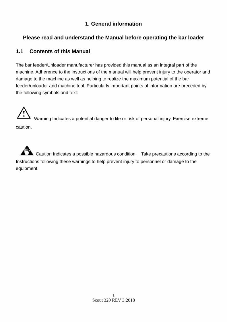
Warning improper adjustment can lead to premature roller wear. Adjustment to the open and close speed of the MAVD/AVD is by way of the thumb screws on the cylinder. Be sure the air supply lines are installed on the correct valve for correct operation. When the lathe collet is closed the MAVD/AVD rollers/blocks will be closed if parameter is set to operate this way. Pressing the Pre-Auto button and the lathe collet closed will command the MAVD/AVD closed. Adjust as required.
MAVD/AVD Closed Speed
Valve
MAVD/AVD Open Speed Valve
Adjustment screw (B) Lock nut (A)

32 Scout 320 REV 3:2018
The MAVD will include an open stop screw. If this screw is screwed in too far this will keep the MAVD from opening fully. This could damage the rollers if larger material is loaded without proper adjustment.
The open stop screw has a jam nut to keep the screw from self-adjusting due to vibrations. Removal of the small cover plate over the roller adjustment screw may be required to access the jam nut.
Installation tip – The MAVD air cylinder normally comes in the orientation shown in the image above. We suggest removing the 4 mounting screws of the air cylinder and rotating the air cylinder body so the air valves are pointing horizontal. This will help with the final cutting of the lathe sheet metal covers.

33 Scout 320 REV 3:2018
5.3.2 AVD/MAVD Block Sets Warning the block sets must be used in same size pairs.
The use of bushing blocks may assist with optimizing the bar feeder performance with certain material, shapes, and operating speeds. 2 Blocks of the same size are required for each AVD/MAVD. Choose a block size that is 2mm larger than your working diameter. The blocks are not intended to clamp onto the material 4 Blocks will be required to outfit the Scout. A variety of sizes are available from Edge Technologies.
Example of blocks installed to MAVD Blocks are optional items, contact Edge Technologies for more information.

34 Scout 320 REV 3:2018
5.4 Pusher Drive Belt
Warning properly trained personnel are required to adjust drive belt
Caution bar feeder and lathe must be emergency stop for belt adjustment Anytime the drive belt requires adjustment follow the procedure below.
1. Place bar feeder and lathe into emergency stop 2. Material may need to be removed form channel if the pusher cannot be moved without
obstruction 3. Open bar feeder hood. 4. Loosen locking screw (1) for the tensioner. 5. Rotate screw (2) clockwise to tighten the belt for suitable tension. 6. Tighten the locking screw (1). 7. Close the bar feeder hood 8. Reset emergency stops and test pusher operation with the hand held pendant.
35 Scout 320 REV 3:2018
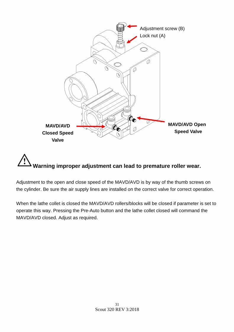
5.5 Channel Set Components
Caution when changing channel set be sure the electrical power to the bar feeder is off.
Warning proper channel set to material diameter is important. Damage to the bar feeder and or the lathe may result. The channel set on the Scout may be changed to a variety of sizes. It is important to note the material diameter to be used in the bar feeder fits in the proper channel set. Channel set components are specific to each channel set.

36 Scout 320 REV 3:2018
Warning be sure to use the correct channel set components for a specific size.
The channel set for the Scout contains many pieces that must be placed in certain locations. The length of the channel section is specific to a region within the aluminum channel rail. It is recommended that 1 channel section at a time is removed and replaced with the conversion piece. All components with in a channel set is specific to the size of that channel set. Combining the channel; sets will not work properly but will produce poor bar feeder performance.
For available guide channel sets reference this manual or contact Edge Technologies for the most up to date information.
tt
Short Feed pusher
Long Feed Pusher
Support Hangers (2)
Note the various lengths of channel
sections. All lengths are in metric.
(mm)

37 Scout 320 REV 3:2018
When changing the channel set it is important to remove then replace one item at a time. If you get ahead of yourself it may take longer setting up the new channel set. The channels pieces are directional and may be installed 180 degrees off.
The channel is directional. Note the flat and angular points on the channel. The angle side is on the side of the carriage.
The short feed pusher screws must be cleaned of any oil and a medium thread lock used. The screws should be replaced after a few times being removed. The button head screw head can be stripped easily.
The pre feed pusher flag should be flat. If the flag is bent it should be bent back to flat or replaced. The mounting screws should be clean and medium strength thread lock be used. Note the short end is the material contact end.

38 Scout 320 REV 3:2018
The lower channel sections fit into the aluminum channel structure. To keep the sections from lifting up a small swivel plate is used. Be sure the plate is engaged over the channel section.
Long feed pusher flag on small diameter channels may be welded. If the flag is excessively bent and entire pusher will be required.

39 Scout 320 REV 3:2018
Pusher Lock Cylinder
Warning incorrect long feed pusher alignment in the pusher swing may cause pusher damage when lowering into the carriage. The Scout uses an air cylinder to guide the long feed pusher flag into the carriage during pusher movement down. When the long feed pusher is reinstalled it is important the hole in the pusher flag lines up with the air cylinder shaft. If this alignment is incorrect you may risk bending the pusher flag when the pusher swings into the channel.

40 Scout 320 REV 3:2018
5.6 Material Measurement sensor/Cutting sensor The material measurement or cutting sensor is an input to the PLC. When material is moved forward during the pre-feed bar change process, the end of the bar makes contact with a steel flap. This flap is moved away from the cutting sensor and triggers the PLC to determine the length of the bar based on the current pusher location. To reset the cutting Sensor flap back to measuring positon a small throttle valve is used to push the flap back into position. This valve is air controlled by the PLC. Note if the measurement sensor is in the wrong state of position bar changes will not occur.

41 Scout 320 REV 3:2018
5.7 Gripper Assembly
Caution the Gripper is a pinch hazard.
Caution the Gripper assembly is a moving component that should always be service with electrical power and air supply removed. The gripper device is used to press material onto the bar feeder collet and remove remnants from the collet. Gripping force is determined by the air supply and not adjustable to the assembly. The gripper jaws are not adjustable however are replicable. The gripper assembly slides fore and aft while gripping the material. The amount of material insertion into the bar feeder collet is based on the pre feed positioning of the material. If the material is placed farther from the gripper, the correct amount of material will not be inside the bar feeder collet. This may lead to material and bar feeder collet separation. Thus causing additional issues. Just the opposite may happen if the material is inserted too far into the bar feeder collet. If the material is placed passed the correct position for optimal insertion during pre-feed, the material may be inserted too far into the bar-feeder collet. If this happens the remnant removal may not occur due to the material is too far into the collet. This may condition may cause a servo alarm during press upon. Adjusting parameter P14 First Feed End Position Setup to fine tune the press upon and press off

42 Scout 320 REV 3:2018
5.8 Material Standards and Requirements
Caution The ends of the bar should be relatively straight to the diameter of the bar to help ensure proper positioning of the bar as it reaches the facing position and to keep the bar pusher from sliding off the bar while feeding the material. In most cases chamfering the lathe side of the bar is required and with spindle rotation at approximately 50rpms.
Material should be relatively straight and clean. A chamfer on the leading bar edge is highly recommended. While bent stock will not necessarily cause problems within the lathe spindle while turning, it may prevent loading if bar condition is such that the bar collides with the back of the lathe spindle or it binds while feeding into the spindle. Bars of small diameter may not pick up properly from the magazine if they are not straight. Excessive chips, burrs or dirt may cause binding within the spindle.
Straightness Requirements Optimum performance of the bar feeder can only be achieved if the material to be run meets specifications for straightness. The maximum allowable bend in a bar is 0.5mm T.I.R. in a 1 meter section (.02” T.I.R per 3 foot section). This tolerance assumes a curvature over the length of the section and not a short kink in the bar. This tolerance is not accumulative. The tolerance for the entire length of the bar is 1.7mm TIR.

43 Scout 320 REV 3:2018
5.8.2 Procedure for checking bar straightness (Reference ASTM B249)
1. Find a suitable surface to allow the bar to rest on V-blocks without any rocking movement.
2. Rotate the bar 360°. Record the dial indicator readings at each location. 3. Calculate both the tolerance for each meter increment and also the tolerance over the
entire length of bar. Compare the recorded values to the required tolerances to determine the bar suitability for operation with a bar feeder.
ROTATEBAR 360°
1.7mm GEOMETRICTOLERANCE ZONE OVER TOTAL LENGTH
INCREMENTS
0.5mm TOLERANCE ZONE FOREACH METER INCREMENT
Ø1.7MM / 3800MMØ0.5MM / METER
Ø0.070" / 12 FTØ0.020" / 36"

44 Scout 320 REV 3:2018
5.8.3 Bar Stock Preparation The bar stock must be free of burrs, chips and excessive dirt. Clean bars will extend the life of the channel guides and bearing unit of the pusher as well as the oil pump impeller. The bar ends should be relatively square to the length of the bar.
Chamfers on the bar ends are generally not needed except when the stock OD is close to the bar pusher OD. In this case the wall of the pusher collet is thin and has only a small lead-in chamfer.
Profiled material such as hex and square stock should have a generous chamfer on the bar feeder end of the bar. This chamfer will help negate the offset of the bar centerline to that of the bar pusher when the stock falls differently into the channel (corners up versus flats up). Chamfers on the lathe end of the bar are not usually required, only an edge break to ensure no burrs remain to snag on the lathe collet. RPM Limiting Factors Certain conditions may limit the lathe to less than full speed rotation of the spindle. Among these conditions are the following:
• Bent bars (bar stock with straightness of less than .5mm/1 meter. • Bars with an irregular profile or shaped material. • Improperly sized guide channel in relation to the bar stock diameter. • Incorrect sizing of guide blocks or incorrect adjustment of steady rollers. • Lack of support in the lathe spindle for the bar pusher. • Characteristics of the bar stock (copper, brass, plastic ect.). • Improper viscosity lubricant in the oil tank of the bar feeder. • Unbalanced bar stock. • Sheared bar ends. • Non-concentric chamfered bar end when using an ejection collet. These factors may work alone or in combination to cause a vibration that requires a reduction in the lathe spindle speed.

45 Scout 320 REV 3:2018
6.1 HMI Operation Description
Warning proper training is required for bar feeder operators. A lack of training may lead to personal or machine damage. The HMI (Human Interface Input) offers intuitive operator input to set the required bar feeder parameters. The navigation through the HMI parameters requires the understanding of the number pad and double button usage. For example to select the F4 screens one would
• Select and hold the shift button and the button F4. • The next screen will prompt for a password input. • Selecting the F3 button will navigate back to the main load screen.
NO. Function 1 LCD Display area 2 Shift 3 Function 4 ESC 5 Number 6 Enter 7 Run light 8 Power light

46 Scout 320 REV 3:2018
Navigation Program Selection:
Press the F1 and F2 key to navigate to the parameter you want to change
:Page up
:Page down
:Back to the main menu
Input numbers as your request from 0 ~
9. Use the 1 button plus the shift to add
the decimal point to any value.
Select the button to enter the
selected value into system memory.
Select to delete the previously
inputted data.

47 Scout 320 REV 3:2018
6.2 Handheld Pendant
NO. Code Function 1. ES2 Emergency STOP
2. DS6 Pre Auto 3. LDS6 Pre Auto light
4. DS10 Manual clamping
5. DS1 Manual advance (Right) Manual retreat (Left)
6. LDS1 Origin point light (Left) 7. L3 Chuck open light
8. L4 Allow feeding on 9. DS7 Manual mode
10. LDS7 Manual mode light 11. DS3 Manual Gripping in/out
12. LDS3 Gripper in light
13. DS4 Manual bar-pusher rise/down
14. LDS4 Bar pusher down light 15. L2 Alarm light
16. L1 Bar end
17. DS5 Automatic start 18. LDS5 Automatic start light
19. DS9 Manual loading
20. DS2 Manual advance (Right) Manual retreat (Left)
21. LDS2 +Z light (Left)

48 Scout 320 REV 3:2018
6.3 Basic Movement Functions
Warning proper training is required for bar feeder operators. A lack of training may lead to personal or machine damage.
Warning be sure lathe is ready for bar feeder operation
( 1 ) Advance / retreat at low-speed
(When the lathe on the left, the motion of and are opposite).
Advance at low-speed, press and .
Retreat at low-speed, press and .
Warning complete understanding of machine operation is required
( 2 ) Automatic work operation
While and the light are on, press and start to work
automatically. Or while and guiding light off, and either or is
on, press and start to work automatically.
Warning be sure if material is in the bar feeder that lathe tooling is out of the way of the bar if it moves into the lathe tooling area.
( 3 ) Resetting the Bar Feeder Home Position
When guide channel up/down light is on move the pusher at least 16 inches
from the home position. Press and simultaneously for 3 seconds to
begin resetting the bar feeder home position.

49 Scout 320 REV 3:2018
6.4 Loading and Unloading Bar Stock
Warning proper training is required for bar feeder operators. A lack of training may lead to personal or machine damage. The following procedure is for left to right feeding. For right to left feeding reverse the jog button use. Loading
• Begin with the channel open and no bar stock present in the guide channel • If the magazine is empty place 1 bar on the magazine
• Press the pre auto button on the hand held remote
• Then press the auto button
• The bar feed will automatically load the new bar to the facing position Unloading
• Place the bar feed in Manual on the hand held remote • Remove the bar stock from the guide bushing and open the collet
• Using the reverse jog button jog the material back to the home sensor
• Press the pre auto button
• Then press the reverse jog button
• The bar feed will then automatically remove the bar from the bar feed collet and continue to move the bar forward with the grippers until the bar presence sensor is clear. The bar feed will then open the channel allowing for bar removal from the guide channel

50 Scout 320 REV 3:2018
6.5 Tower Light
The indicator light provides quick visual
indication of bar feeder status.
The status conditions below,
When Red light is on, bar feeder is in
emergency stop.
When Green light is on, bar feeder is in
machining mode.
When Green light is flashing, bar feeder is in
bar change operation.

51 Scout 320 REV 3:2018
6.6 HMI Operator Functions
To access the F menus use the table below. Selecting the shift and F keys together are required for selection.
1. Press the key:
2. Press the key:
3. Press the key:
4. Press the key:
5. Press the key:
6. Press the key:
7. Press the key:
8. Press the key:
9. Press the key:

52 Scout 320 REV 3:2018
6.6.2 Changing the Unit of Measure
Warning only properly trained individuals should perform adjustment to parameters of bar feeder.
The standard shipping unit of measure of the Scout 320 is metric. Imperial unit of measure can be used however this requires the reprograming of the PLC, HMI and a change to the servo drive parameter. Due to this procedure Edge Technologies must change the unit of measure. Normally when the bar feeder is ordered the customers preference for unit of measure is programmed prior to machine shipping. If the unit of measure is to be changed the PLC and HMI may be returned to Edge Technologies for reprogramming. Upon receiving the updated PLC and HMI the parameters will need to be set. The servo drive parameter PA15 will need to be changed as well. Do not change the parameter PA15 only as this will not change the HMI display for metric or imperial.
1. HMI and PLC with desired unit of measure. 2. On the servo drive in the electrical cabinet you need to change a parameter. The
parameter that needs to be changed is the PA15 Parameter. 3. When changing the software over to Metric, you need to set the parameter at 299. 4. When changing the software over to Inch, you need to set the parameter at 1186.
6.6.3 Parameter Flowchart The following pages reflect the bar feeder’s menus expanded for simple visualization. If you know the name of the parameter you want to view, locate it on the sheet then navigate to the correct F keys and menus. Use pass code 258 to access the code protected menus. Anytime a parameter is changed it should be recorded in the parameter worksheet. This worksheet is normally completed by the Edge Technologies Technician during the installation process.

53 Scout 320 REV 3:2018
P. 6 – 9TO continue
Barfeeder MonitorL01 Finished product lengthL02 Feed too long safety of chuck closeL03 Feed too short safety of chuck closeL04 Bar pusher move forward of chuck openL05 Bar pusher backward safety of chuck open S01 Speed of chuck openQ01 Torque of chuck openS02 Speed of chuck closeQ02 Torque of chuck closeS03 Manual feed speedQ03 Torque of manualP01 Movable anti-vibration opening positionP02 Movable anti-vibration second close positionP19 Chuck facing distance fine tuningP20 Bar end position fine tuning
※ Depend on work piece proportion.
Need secret code to continue
※
※※※※
Alarm data chart AL.P1Alarm data chart AL.P2Alarm data chart AL.P3Alarm data chart AL.P4Interface signal monitorPLC INPUT signal monitorPLC OUTPUT signal monitorPLC LadderPLC ERROR
P. 6 – 10TO continue
P22 Movable anti-vibration early close position

54 Scout 320 REV 3:2018
Q01 Torque of chuck openQ02 Torque of chuck closeQ03 Torque of manualQ04 First feeding torqueQ05 Chuck entry torqueQ06 Remnant push out torque
P01 Movable anti-vibration opening positionP02 Movable anti-vibration second close positionP03 First anti-vibration opening positionP04 First anti-vibration closing positionP05 First anti-vibration second close position P06 2TH anti-vibration opening position P07 3TH anti-vibration opening position P08 4TH anti-vibration opening position
P10 Chuck facing distanceP11 Bar end position P12 Stop providing oilP13 First stop position for small bar pusherP14 First feed end positionP15 Remnant push out positionP16 Inching retract strokeP17 Bar push retract strokeP18 Bar push return positionP19 Chuck facing distance fine tuningP20 Bar end position fine tuning
T01 Chuck open over timeT02 Chuck close over timeT03 Thrust of chuck close delayT04 Retract delay timeT05 Inching signal ON timeT06 Inching signal OFF timeT07 Start signal delay time
L01 Finish product lengthL02 Feed too long safety of chuck closeL03 Feed too short safety of chuck closeL04 Bar pusher move forward of chuck openL05 Bar pusher backward safety of chuck open L06 Inching number setup
S01 Speed of chuck openS02 Speed of chuck closeS03 Manual feed speedS04 First feeding speedS05 Chuck enter speedS06 Remnant push out speedS07 Bar pusher draw back speed
P09 5TH anti-vibration opening position
P22 Movable anti-vibration close length
T08 Timer setting after chuck open to reduce torque

55 Scout 320 REV 3:2018
F01 Movable anti-vibration open or close follow chuckF02 Facing distance modeF03 Feeding mode of chuck openF04 Synchronization deviceF05 Change start modeF06 Lathe modeF07 Feeding direction modeF08 Change start signal to CNCF09 Safety door signal Of latheF10 End of bar change modeF11 Select bar pusher work methodF12 Select loading methodF13 Bar feeder typeF14 Bar end mode

56 Scout 320 REV 3:2018
F1 Parameter List Accessed without passcode Parameter NO Parameter name Parameter description
Barfeeder Monitor
L01 Finished product length Use the Bar end position to generate a signal for bar end.
L02 Feed too long safety of chuck close
Prevents bars from feeding over the length of finished product. To disable parameter function, please set the value to zero.
L03 Feed too short safety of chuck close
Prevents bars from feeding length less than finished product. To disable parameter function, please set the value to zero.
L04 Bar pusher move forward of chuck open
Under automatic mode, the bar pusher move forward and the distance is large than the setting value during chuck opened.
L05 Bar pusher backward safety of chuck open
Under automatic mode, when the bar pusher move backward and the distance is large than the setting value during chuck opened.
S01 Speed of chuck open The speed of the bar pusher moves forward under automatic mode and the chuck is opened.
Q01 Torque of chuck open The torque of the bar pusher moves forward when the chuck is opened under automatic mode.
S02 Speed of chuck close The speed of the bar pusher moves forward under automatic mode and the lathe chuck is closed.
Q02 Torque of chuck close The torque of the bar pusher moves forward when the chuck is closed under automatic mode.
S03 Manual feed speed The motor turning speed when the bar pusher move forward under manual mode.
Q03 Torque of manual The motor torque of the bar pusher moves forward or backward under manual mode.
P01 Movable anti-vibration opening position
The position of the movable anti-vibration device opened under automatic operation.
P02 Movable anti-vibration second close position
The Second close position of movable anti-vibration device stands for the position of bar pusher is over the value of parameter, P01; the anti-vibration can operate the second close function to clamp bar pusher.
P19 Chuck facing distance fine tuning
Fine tuning for chuck facing position as the datum of chuck facing distance P10. If the adjustment quantity is less than 200 or large than 200, please adjust the value of chuck facing distance P10.
P20 Bar end position fine tuning
Fine tuning for the bar end position. If the fine tuning quantity is less than 200 or large than 200, then adjust the parameter P11, bar end position value.
P22 Movable anti-vibration early close position
Under Auto-Mode, Anti-vibration Device will close when bar pusher reached this parameter setup position.

57 Scout 320 REV 3:2018
Parameter description: This also known as the Long Feed Safety. Prevents
bars from feeding over the length of finished product
length plus the additional length of the safety value.
To disable parameter function, set the value to zero.
Setting method: Input the required length.
For Example: Finished product length + Tolerance normally 5mm
(however you may add more if required) = Long feed
safety. Setting the value too close to the Finished
Product length could cause alarms.
Previous page
Next page
Home page
3.7XL Generally value: Setting range: 0~2200mm
Setting value:

58 Scout 320 REV 3:2018
Parameter description: This also known as the Short Feed Safety. Prevents
bars from feeding under the length of finished product
length plus the subtracted length of the safety value.
To disable parameter function, set the value to zero.
Setting method: Input the required length.
For Example: Finished product length - Tolerance normally 5mm
(however you may decrease more if required) = Short
feed safety. Setting the value too close to the
Finished Product length could cause alarms.
Previous page
Next page
Home page
3.7XL Generally value: Setting range: 0~2200mm
Setting value:

59 Scout 320 REV 3:2018
Parameter description: On a Swiss headstock lathe while in automatic mode,
when the collet opens the bar pusher will push the
material to a stop, that is if M-code feed is off. If this
stop is not there the machine will alarm once the
pusher moves to the setting value.
Setting method: Input the required length.
Note: The parameter is disabled if set to zero. This setting is
monitored when
Previous page
Next page
Home page
3.7XL Generally value: Setting range: 0~550mm
Setting value:
Parameter description: In automatic mode if the pusher is pushed backward
once collet opens to the setting value the machine
will alarm.
Setting method: Input the required length.
Note: The parameter is disabled if set to zero.
Previous page
Next page
Home page
3.7XL Generally value: Setting range: 0~500mm
Setting value:
Parameter description: During bar change and the introduction of new stock
to the chuck facing position if an obstruction is
detected, bar pusher will start the inching movement
and the frequency according to this setting value. If
the new bar fails to reach chuck facing position and
inching frequency exceeds the setting value then bar
feeder will show Alarm16.
Setting method: Input the number of required inching movement
times.
Note: It is advised that both ends of the bar stock is
chamfered to assist with loading of the bar.
Previous page
Next page
Home page
3.7XL Generally value: Setting range: 0~50 times
Setting value:

60 Scout 320 REV 3:2018
Parameter description: The speed of the pusher in automatic mode when
lathe collet opens.
Setting method: Set this value in accordance to the bar material size
and length of material.
Note: When setting value is too high it could cause servo
failure or alarms. When a material change over from
a small diameter stock to a large diameter stock or
vice versa this value may require adjustment for error
free production.
Previous page
Next page
Home page
3.7XL Generally value: Setting range: 0~500rpm
Setting value:
Parameter description: The speed of the pusher in automatic mode when
lathe chuck close.
Setting method: Set to desired speed requirement.
Note: When setting value is too high it could cause servo
failure. Setting is normally 0 since this parameter is
rarely used.
Previous page
Next page
Home page
3.7XL Generally value: Setting range: 0~500rpm
Setting value:
Parameter description: The pusher speed during manual operation.
Setting method: Set this value in accordance to the bar material size
and length torque of chuck close to adjust speed.
Note: When setting value is too high it could cause servo
failure or alarms. When a material change over from
a small diameter stock to a large diameter stock or
vice versa this value may require adjustment for error
free production.
Previous page
Next page
Home page
3.7XL Generally value: Setting range: 0~500rpm
Setting value:

61 Scout 320 REV 3:2018
Parameter description: During bar change when the bar has been loaded into
the channel the pre-feed pusher will then move the
bar to the first feed position.
Setting method: Input the required speed for feeding speed
parameter.
Note: If the speed of pusher is too fast this may cause bar
material to pass desired first feed position. Lowering
the value will slow done the pre-feed pusher
movement.
Previous page
Next page
Home page
3.7XL Generally value: Setting range: 0~500rpm
Setting value:
Parameter description: The speed of pusher as it enters towards the work
holding area. On a Swiss lathe this is just behind the
guide bushing to the chuck facing position.
Setting method: Input the required speed for feeding into the work
holding area.
Note: Set actual speed to avoid crashing. This only changes
the speed from a predetermined position. The
position of speed change is not adjustable. This
speed is normally slow to keep from over shooting the
desired position.
Previous page
Next page
Home page
3.7XL Generally value: Setting range: 0~500rpm
Setting value:
Parameter description: The speed of the bar pusher pushes out remnant
when receiving bar end signal.
Setting method: Input the required speed.
Note: Set actual speed to avoid crashing. This is only used
when a front eject collet is installed and the process
requires the remnant to be ejected from the lathe
side.
Previous page
Next page
Home page
3.7XL Generally value: Setting range: 0~500mm
Setting value:

62 Scout 320 REV 3:2018
Parameter description: Retracting speed of the bar pusher in manual or
automatic mode.
Setting method: Input the required speed.
Note: If this speed is too fast the remnant may become
separated from the pusher collet.
Previous page
Next page
Home page
3.7XL Generally value: Setting range: 0~1000mm
Setting value:
Parameter description: The torque of the pusher movement forward when in
automatic mode and lathe chuck open.
Setting method: Set this value in accordance to the bar material size
and length of material.
Note: When setting value is too high it could cause servo
failure. When a material change over from a small
diameter stock to a large diameter stock or vice versa
this value may require adjustment for error free
production.
Previous page
Next page
Home page
3.7XL Generally value: Setting range: 0~800mm
Setting value:
Parameter description: The torque of the pusher movement forward when in
automatic mode and lathe chuck close.
Setting method: Set this value in accordance to the bar material size
and length of material.
Note: When setting value is too high it could cause servo
failure. Setting is normally 0 since this parameter is
rarely used.
Previous page
Next page
Home page
3.7XL Generally value: Setting range: 0~800mm
Setting value:

63 Scout 320 REV 3:2018
Parameter description: The torque of bar pusher movement forward in
manual operation mode.
Setting method: According to required torque and speed of manual
operation mode to adjust torque.
Previous page
Next page
Home page
3.7XL Generally value: Setting range: 0~800mm
Setting value:
Parameter description: During bar change when the bar has been loaded into
the channel the pre-feed pusher will then move the
bar to the first feed position.
Setting method: According to required torque and speed of manual
mode to adjust torque.
Note: If the torque of pusher is too low this may cause bar
material to produce an alarm.
Previous page
Next page
Home page
3.7XL Generally value: Setting range: 0~800mm
Setting value:
Parameter description: The speed of pusher as it enters towards the work
holding area. On a Swiss lathe this is just behind the
guide bushing to the chuck facing position.
Setting method: Input the required torque for feeding into the work
holding area.
Note: Set actual speed to avoid crashing. This only changes
the speed from a predetermined position. The
position of torque change is not adjustable.
Previous page
Next page
Home page
3.7XL Generally value: Setting range: 0~800mm
Setting value:

64 Scout 320 REV 3:2018
Parameter description: The torque of the bar pusher pushes out remnant
when receiving bar end signal.
Setting method: Input the required torque.
Note: Set actual torque to avoid crashing. This is only used
when a front eject collet is installed and the process
requires the remnant to be ejected from the lathe
side.
Previous page
Next page
Home page
3.7XL Generally value: Setting range: 0~800mm
Setting value:
Parameter description: In automatic mode the movable anti-vibration device
must open for the pusher collet to pass without
damage to the rollers or blocks.
Setting method: Position the lathe headstock to the Z limit position
nearest the bar feeder, normally called the Z- over
travel position. Position the pusher collet 1 inch
before the MAVD. Record the position displayed on
the HMI for the parameter value.
Note: If the distance value is too high the MAVD will not
open.
Previous page
Next page
Home page
3.7XL Generally value: Setting range: 0~5000mm
Setting value:
Parameter description: In automatic mode the movable anti-vibration device
can be closed on the pusher once the pusher collet
has passed the roller/blocks.
Setting method: Add 150mm to the MAVD opening position.
Note: To disable this parameter function, set the value to
zero.
Previous page
Next page
Home page
3.7XL Generally value: Setting range: 0~5000mm
Setting value:

65 Scout 320 REV 3:2018
Parameter description: In automatic mode setting 1st Anti-Vibration Device
open position. This is the roller/block device inside
the bar feeder nearest the material sensor.
Setting method: In manual mode move pusher collet forward until
30~50mm before 1st anti vibration device. Then input
the current position.
Note: First anti–vibration should be opened before the collet
arrives to avoid the material separation from the collet
and damaging the rollers/blocks.
Previous page
Next page
Home page
3.7XL Generally value: Setting range: 0~5000mm
Setting value:
Parameter description: In automatic mode during pre-feeding the AVD will
close lifting the bar to center it while loading into the
spindle.
Setting method: Allow bar end to pass through the AVD then input the
required length.
Note: To disable this parameter function, set the value to
zero. The bar end must be through the AVD before
closing or damage to the rollers/blocks will occur.
Previous page
Next page
Home page
3.7XL Generally value: Setting range: 0~5000mm
Setting value:
Parameter description: In Auto-Mode, this parameter is to setup how much
distance to go before the clamping of the AVD closes
again, after passing "First anti-vibration opening
position."
Setting method: Input the required length.
Note: To disable this parameter function, set the value to zero.
Previous page
Next page
Home page
3.7XL Generally value: Setting range: 0~5000mm
Setting value:

66 Scout 320 REV 3:2018
Not used on Scout
Parameter description: 2nd Anti-Vibration Device open position in working
mode.
Setting method: In manual mode pusher will be pushed forward until
30~50mm before 2nd anti vibration device. Then
input the current position.
Note: The Second anti–vibration should be opened before
the end of the push bar will be arrived to avoid the
material was separated from the collet.
Previous page
Next page
Home page
3.7XL Generally value: Setting range: 0~5000mm
Setting value:
Not used on Scout
Parameter description: 3rd Anti-Vibration Device open position in working
mode.
Setting method: In manual mode pusher should be pushed 30~50mm
before 3rd anti vibration device. Then input the
current position.
Note: The Third anti–vibration should be opened before the
end of the push bar will be arrived to avoid the
material was separated from the collet.
Previous page
Next page
Home page
3.7XL Generally value: Setting range: 0~5000mm
Setting value:

67 Scout 320 REV 3:2018
Parameter description: 4th Anti-Vibration Device open position in working
mode.
Setting method: In manual mode pusher will be pushed forward until
30~50mm before the 4th anti vibration device.
Note: The Forth anti–vibration should be opened before the
end of the push bar will be arrived to avoid the
material was separated from the collet.
Previous page
Next page
Home page
3.7XL Generally value: Setting range: 0~5000mm
Setting value:
Parameter description: 5th Anti-Vibration Device open position in working
mode.
Setting method: In manual mode pusher should be pushed forward
until 30~50mm before the 5th anti vibration device.
Once at the desired open position input the current
position displayed.
Note: The Five anti–vibrations should be opened before the
end of the push bar will be arrived to avoid the
material was separated from the collet.
Previous page
Next page
Home page
3.7XL Generally value: Setting range: 0~5000mm
Setting value:

68 Scout 320 REV 3:2018
Parameter description: Chuck facing position is the distance between the
measurement sensor to the facing position. Bar is
placed in this position only during a bar load. (as
picture 2)
Setting method: According to below drawings to set the distance from
A - B point. In addition input it by mm unit.
Note: On a Swiss headstock the facing position is about
10mm behind the guide bushing gripping pads.
Previous page
Next page
Home page
3.7XL Generally value: Setting range: 0~4000mm
Setting value:
Chuck Facing Distance Setup
Parameter P10
Chuck Facing Distance Setup
Parameter P10
Guide Bushing

69 Scout 320 REV 3:2018
Parameter description: This position is the maximum working limit. If pusher
position value is larger than the bar end setting the
bar feeder will send the end of bar signal to the lathe.
Setting Mode for
fixed lathe: In manual mode move pusher into lathe spindle
until 5~10mm before lathe chuck jaws. Then confirm
the input it to be bar end position.
Setting Mode for
Swiss lathe: In the manual mode move the headstock to +Z limit
position and move pusher with no bar forward until
collet makes contact with the collet. Note the
position on the HMI and subtract 10mm from the
value. Place that value into the Bar End Position.
Note: Reference figure 3
Previous page
Next page
Home page
3.7XL Generally value: Setting range: 0~4000mm
Setting value:
5~10mm
Pusher moved into spindle
Chuck
5~10mm Pusher

70 Scout 320 REV 3:2018
Parameter description: In automatic mode the pusher position oil will be
turned off.
Setting method: In manual mode move pusher forward to desired stop
oil location. Input the current position for parameter.
Note: Oil provides oil for lubrication and cooling.
Previous page
Next page
Home page
3.7XL Generally value: Setting range: 0~4000mm
Setting value:
Parameter description: This parameter is to prevent hard impact on new bar
material end because of small pusher block high
speed during loading a new bar material. This
parameter will let the small pusher block to slow down
to prevent hard impact to the new bar material.
Setting method: Input the required position.
Previous page
Next page
Home page
3.7XL Generally value: Setting range: 0~4000mm
Setting value:
Parameter description: The pre feed pusher will move the bar to the gripper
position for gripping.
Setting method: Move the pre feed pusher to the desired location in
front of the gripper jaws. Input position into HMI.
Note: The Scout uses a moving gripper assembly, use
caution when positioning for a new bar.
Previous page
Next page
Home page
3.7XL Generally value: Setting range: 0~2000mm
Setting value:
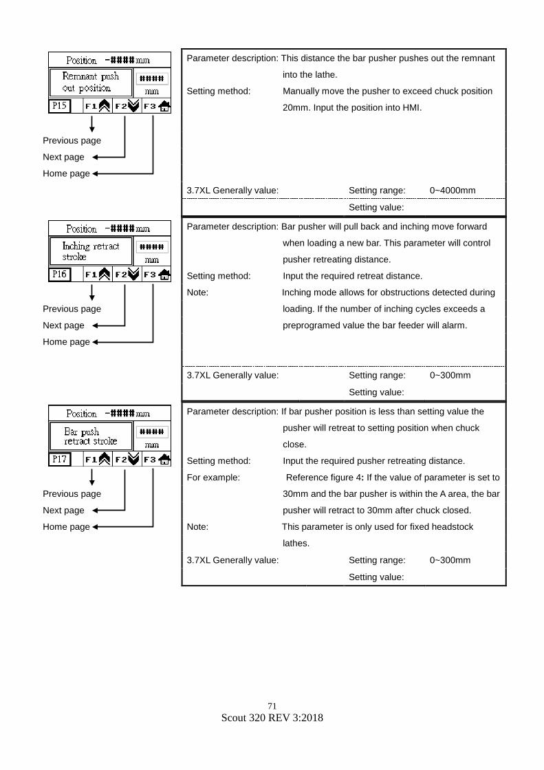
71 Scout 320 REV 3:2018
Parameter description: This distance the bar pusher pushes out the remnant
into the lathe.
Setting method: Manually move the pusher to exceed chuck position
20mm. Input the position into HMI.
Previous page
Next page
Home page
3.7XL Generally value: Setting range: 0~4000mm
Setting value:
Parameter description: Bar pusher will pull back and inching move forward
when loading a new bar. This parameter will control
pusher retreating distance.
Setting method: Input the required retreat distance.
Note: Inching mode allows for obstructions detected during
loading. If the number of inching cycles exceeds a
preprogramed value the bar feeder will alarm.
Previous page
Next page
Home page
3.7XL Generally value: Setting range: 0~300mm
Setting value:
Parameter description: If bar pusher position is less than setting value the
pusher will retreat to setting position when chuck
close.
Setting method: Input the required pusher retreating distance.
For example: Reference figure 4: If the value of parameter is set to
30mm and the bar pusher is within the A area, the bar
pusher will retract to 30mm after chuck closed.
Note: This parameter is only used for fixed headstock
lathes.
Previous page
Next page
Home page
3.7XL Generally value: Setting range: 0~300mm
Setting value:

72 Scout 320 REV 3:2018
Parameter description: If bar pusher position is over the setting value the
pusher will retreat to setting position when chuck
close. In order to prevent friction and vibration caused
from pusher going into the lathe spindle too far.
Setting method: By manual operation let the bar pusher move into the
spindle inside around 1 / 3 of its length. To ensure not
to touch the spindle and input the current position.
For example: Reference figure 4: If the value of parameter is set to
800mm and the bar pusher is out of the A area, the
bar pusher will retract to 800mm after chuck closed.
Note: This parameter is only used for fixed headstock
lathes.
Previous page
Next page
Home page
3.7XL Generally value: Setting range: 0~3000mm
Setting value:

73 Scout 320 REV 3:2018
Parameter description: Fine tuning for bar end position based on chuck facing
position. If the tuning value is greater than 200mm
then change the facing position directly.
Setting method: Input the required value.
Note: The value may subtract or add for fine tuning.
Previous page
Next page
Home page
3.7XL Generally value: Setting range: -200~200mm
Setting value:
Parameter description: Fine tuning for bar end position based bar end
position. If the tuning value is greater than 200mm
then change the bar end position directly.
Setting method: Input the required value.
Note: The value may subtract or add for fine tuning.
Previous page
Next page
Home page
3.7XL Generally value: Setting range: -200~200mm
Setting value:
Parameter description: Under Auto-Mode, Anti-vibration Device will close
when bar pusher reached this parameter setup
position.
Setting method: Input the required length.
Note: To disable this parameter function, set the value to
zero.
Previous page
Next page
Home page
3.7XL Generally value: Setting range: 0~2000mm
Setting value:

74 Scout 320 REV 3:2018
Parameter description: This is open collet timeout. If the set time is exceeded
the bar feeder will set ALARM 29 will display and stop
operating.
Setting method: When the setting value is 0, the parameter function
will be disabled.
Previous page
Next page
Home page
3.7XL Generally value: Setting range: 0~999 seconds
Setting value:
Parameter description: This is closed collet timeout. If the set time is
exceeded the bar feeder will set ALARM 32 will
display and stop operating.
Setting method: When the setting value is 0, the parameter function
will be disabled.
Previous page
Next page
Home page
3.7XL Generally value: Setting range: 0~999 seconds
Setting value:
Parameter description: This is closed collet push delay. In automatic mode,
pusher pushes bar material into lathe and collet close
to work. Once the collet closes the pusher will
continue to push for the set time.
Setting method: Input the required time.
Note: Setting the time too long may cause alarms.
Previous page
Next page
Home page
3.7XL Generally value: Setting range: 0~9.9 seconds
Setting value:

75 Scout 320 REV 3:2018
Parameter description: This is an end of bar retreat delay. Once the End Of
Bar signal is on and the lathe collet opens the bar
pusher will delay the set time prior to returning home.
Setting method: Input the necessary delay time.
Previous page
Next page
Home page
3.7XL Generally value: Setting range: 0~9.9 seconds
Setting value:
Parameter description: This is also known as impulses on. During loading of
a new bar the lathe spindle can be commanded to
rotate if wired to do so.
Setting method: Input required time.
Note: Normally not used on Swiss headstocks. Lathe must
support function.
Previous page
Next page
Home page
3.7XL Generally value: Setting range: 0~9.9 seconds
Setting value:
Parameter description: This is also known as impulses off. During loading of
a new bar the lathe spindle can be commanded to
stop rotating if wired to do so.
Setting method: Input required time.
Note: Normally not used on Swiss headstocks. Lathe must
support function.
Previous page
Next page
Home page
3.7XL Generally value: Setting range: 0~9.9 seconds
Setting value:

76 Scout 320 REV 3:2018
Parameter description: Delay time for sending the cycle start signal once a
new bar is placed to the chuck facing position.
Setting method: If the time is set too long it may cause the lathe to
exceed the programed standby timer.
Previous page
Next page
Home page
3.7XL Generally value: Setting range: 0~9.9 seconds
Setting value:
Parameter description: In automatic mode the pre-feeding pusher will push
bar material when the pusher rising. Then anti
vibration device will open when pusher pushes bar
material to touch chuck facing sensor.
Setting method: Input the required length.
Note: To disable this parameter function, set the value to
zero.
Previous page
Next page
Home page
3.7XL Generally value: Setting range: 0~9.9
Setting value:

77 Scout 320 REV 3:2018
Parameter description: Set the MAVD operation of open and close to match
the open and close of the lathe collet signal.
0 - disable
1 – enable
Setting method: Input the desired function character
Previous page
Next page
Home page
3.7XL Generally value: Setting range: 0~1
Setting value:
Parameter description: Select placing a new bar to a stop or to a position.
“0: To the stop”: The new bar will be pushed to the chuck facing stop
position and keep pushing until the lathe chuck is
closed.
“1: In position”: The new bar will be pushed to the setting chuck
facing position by the parameter and the bar pusher
will stop right away.
Setting method: Input the desired function character
Previous page
Next page
Home page
3.7XL Generally value: Setting range: 0~1
Setting value:

78 Scout 320 REV 3:2018
Parameter description: During production the bar advancement may set to
push to a stop or to a position when the chuck opens.
“0: To the stop”: The bar pusher pushes the bar to the product
finishing stop position and keeps pushing until collet
closes and closed collet timer expires if set..
“1: In position”: The bar pusher pushes the bar to the product finish
length position and stop pushing. Normally a push
confirm signal is normally used as well.
Setting method: Input the desired function character
Previous page
Next page
Home page
3.7XL Generally value: Setting range: 0~1
Setting value:
Parameter description: This turns the synchronizing device off or on.
“0: Disuse“: Bar-headstock synchronization is disabled; the bar is
continuously driven by the feed motor. Used with
Fixed headstock lathes.
“1: Activated“: Headstock synchronization is on when lathe collet
are closed (feed motor stopped), and synchronization
is off when lathe collet is open (feed motor running).
Used with Swiss headstock lathes.
Setting method: Input the desired function character
Previous page
Next page
Home page
3.7XL Generally value: Setting range: 0~1
Setting value:
Parameter description: Two modes of operation are available, when mode
“0:ON-line mode”, bar feeder starts operating along
with lathe. This is normal bar feeder operation. For
testing purpose Demo mode will simulate bar feeding
and bar change process without the lathe inputs. set
the mode for“1: Demo mode”.
Setting method: Input the desired function character
Previous page
Next page
Home page
3.7XL Generally value: Setting range: 0~1
Setting value:

79 Scout 320 REV 3:2018
Parameter description: Set the mode for use what kind of type of lathe.
0: Swiss headstock type of lathe
1: Fixed headstock type of lathe
Setting method: Input the desired function character
Previous page
Next page
Home page
3.7XL Generally value: Setting range: 0~1
Setting value:
Parameter description: Set the feeding direction of bar feeder fed along with
type of lathe.
0: Left feed to right feed direction
1: Right feed to left feed direction
Setting method: Input the desired function character
Previous page
Next page
Home page
3.7XL Generally value: Setting range: 0~1
Setting value:
Parameter description: Select modes for the Cycle start signal of the bar
feeder to the lathe.
0: Under automatic mode, Cycle start signal will be
sent to lathe after bar changed and while lathe chuck
is open.
1: The cycle start signal will be sent after bar
changed.
2: Disable.
Setting method: Input the desired function character
Previous page
Next page
Home page
3.7XL Generally value: Setting range: 0~2
Setting value:

80 Scout 320 REV 3:2018
Parameter description: Some lathe models will output a lathe door signal to
the bar feeder. When the lathe door is open the bar
feeder will alarm. The input circuit X23 on the PLC
may be changed on how the circuit is monitored by
the PLC as a Normally open or Normally Closed
circuit.
Setting method: Input the desired function character
Previous page
Next page
Home page
3.7XL Generally value: Setting range: 0~1
Setting value:
Parameter description: Selects different modes for dealing with remnant after
bar changed.
0: Pull back the remnant into the bar feeder.
1: Push out the remnant into the lathe.
2: Push out the remnant into the lathe by a new bar
when bar end signal is sent and bar feeder will
change another new bar.
Setting method: Input the desired function character
Previous page
Next page
Home page
3.7XL Generally value: Setting range: 0~2
Setting value:

81 Scout 320 REV 3:2018
Parameter description: Select the bar pusher forward or backward under
automatic mode.
0: The bar pusher forward when chuck closed.
(Standard) Swiss Headstock
1: The bar pusher backward when chuck closed.
(Special) Fixed Headstock
Note: If parameter 1 is selected, parameter P17 (Bar
pusher return stroke) and parameter P18 (Bar
pusher return position) must be set accordingly.
Setting method: Input the desired function character
Previous page
Next page
Home page
3.7XL Generally value: Setting range: 0~1
Setting value:
Parameter description: The parameter not available.
Previous page
Next page
Home page
3.7XL Generally value: Setting range: 0~1
Setting value:
Parameter description: When bar end occurs the PLC will send the End of
bar signal when the chuck opens or when the chuck
closes.
0: Chuck close On
1: Chuck open On
Setting method: Input the desired function character
Previous page
Next page
Home page
3.7XL Generally value: Setting range: 0~1
Setting value:

82 Scout 320 REV 3:2018
Parameter description: Set the date and time of system to record data.
Home page
3.7XL Generally value: Setting range: NO
Setting value:
Parameter description: Select the proper language of the information
displayed:
0:Traditional Chinese
1:English
2:Simplified Chinese
3:Spanish
Setting method: Input the desired function character
Home page
3.7XL Generally value: Setting range: 0~3
Setting value:
Parameter description: Shift to display LOGO homepage on the HMI screen.
Home page
3.7XL Generally value: Setting range: NO
Setting value:

83 Scout 320 REV 3:2018
Parameter description: This parameter allows technician to test each signal
output to the lathe.
Setting method: These parameters are only outputted under manual
mode of both lathe and bar feeder, otherwise it may
cause danger.
Next page
Home page
3.7XL Generally value: Setting range: NO
Setting value:
Parameter description: This parameter allow technician to test each signal
output on interface is continued to lathe.
Setting method: These parameters are only outputted under manual
mode of both lathe and bar feeder, otherwise it may
cause danger.
Previous page
Home page
3.7XL Generally value: Setting range: NO
Setting value:
Parameter description: To displays the version number of PLC and HMI
programs.
Home page
3.7XL Generally value: Setting range: NO
Setting value:

84 Scout 320 REV 3:2018
Parameter description: This sets all parameters to original value. Select the
length of the bar feeder you have. All parameters will
be cleared and must be set for bar feeder to function
properly.
1: 2.7LL
2: 3.2LL
3: 3.7LL
Setting method: Input the desired function character
Note: When setting this parameter 1-3, all HMI and timer
will return to “0”, and then start operating.
*All parameters will be cleared and must be set for bar feeder to function
properly.
Home page
3.7XL Generally value: Setting range: 0~3
Setting value:
Parameter description: For recognizing the number of PLC and HMI
programs to suit for lathe model.
Note: Do not adjust this parameter. Contact Edge
Technologies for further assistance.
Home page
3.7XL Generally value: Setting range: 99999
Setting value: 100

85 Scout 320 REV 3:2018
Parameter description: This parameter sets the model of bar feeder.
0: SCOUT 320
1: Unique / Compact
The Unique / Compact uses a scroll loading
magazine, select 1 if the magazine contains this type.
Previous page
Next page
Home page
3.7XL Generally value: Setting range: 0~1
Setting value:
Parameter Description: To set transmission ratio of the bar feeder.
0: Sprocket mode
1: Pulley mode
Note: The correct transmission mode must be correct for
position data to be correct.
Previous page
Home page
3.7XL Generally value: Setting range: 0~1
Setting value:

86 Scout 320 REV 3:2018
7. Maintenance 7.1 Maintenance Chart
Warning prior to bar feeder maintenance turn off 3 phase power to the bar feeder and place the lathe into emergency stop
Warning prior to pneumatic system service be sure to evacuate the system. Observe the following guidance
• For consistent operation of the bar feeder, please do maintenance checks regularly. • The area around the bar feed should be kept clean to avoid safety issues. • Using petroleum or other solvents may damage plastic components. • Dust and or wipe down the bar feeder with a mild cleaner daily
Component Action Frequency
Hours Regular Period
200 1250 2500 200 1250
Collet Check wear ●
Guide channel Check wear and clean ●
Feeding belt Lubrication ●
Tension ●
Air cleaner Check ●
7.1.2 Inspecting the pusher collet and revolving tip Check that revolving tip (A) rotates smoothly and does not have excessive run out. If any problems detected the tip should be replaced.
Check that pusher collet (B) has the correct tension. The collet should press on a bar with some pressure required. The collet should be able to retain a proper length remnant. Inspect for cracks of pieces of material missing. Replace as required.

87 Scout 320 REV 3:2018
Warning always use proper eye protection when working
with compressed air systems. 7.1.3 Inspecting the air regulator
• Check the bottle (B) for water.
• Press button (C) to exhaust water out of bottle.
Inspect for the following
• Air leaks
• Cracks
• Oil level ok
• Secure mounting
• Proper air regulation is set Repair any issues above
7.1.4 Pneumatic System Lubrication The pneumatic systems incorporates a self-oiling system into the air regulator. Adjustment to the oiler is made via the adjustment ring. Set the dial position based on the oil needs for the operating strategy employed for the bar feeder. The lower the number setting the less oil will be dispensed into the system. Verify pneumatic system oil type in section 2.3.2

88 Scout 320 REV 3:2018
8 Troubleshooting
Caution troubleshooting and diagnosis of the bar feeder must be carried out by a trained and qualified technician. Contact Edge Technologies if a qualified technician is unavailable. The PLC monitors various systems with in the bar feeder. When problems are detected with in this system an alarm code will be displayed on the HMI. The following pages will list the alarm number, the name of the alarm and the possible causes of the alarm.

89 Scout 320 REV 3:2018
8.1 Troubleshooting Chart
ITEM Cause Solution
Unable to start the bar Feeder.
Without power. Check the power source.
In emergency. Restart. The bar feeder is reset but the bar feeder can’t auto to start.
The lathe is sending signal. Check the connection.
Air devices are not functioning
Compressed air is not present.
Check the air supply.
Situation Cause Solution
Material not loading into channel
The material position plates are too low. Material lift plates missing bar when raising.
Adjust the material position plates. Increase bar diameter setting on magazine.
Situation Cause Solution
Material is unable to be inserted into the bar feeder collet
The adjustment of the clamp device is not correct.
Re-adjust.
The diameter of the collet and material are different.
Change to correct collet size.
The end of the material is too rough.
Chamfering before loading material.
The air pressure is without chamfer.
Check the pressure.
Material feeding failure
Situation Cause Solution Material can't feed into the spindle smoothly
The center of the bar feeder and the lathe isn't correct
Re-adjust the alignment
Material can't feed into the chuck of the lathe smoothly
The front of the material is too rough.
Chamfering before loading material.

90 Scout 320 REV 3:2018
8.2 HMI Alarm Message
Alarm Number CURE
※Remove obstruction. ※Channel section not in place properly.
※Check the value of long feed safety is correct. ※Check the turret stop location is correct. Set too far.
※Check the value of short feed safety is correct. ※Check the turret stop location is correct, set to short. ※Possible obstruction of the pusher or bar from obtaining
position.
※During bar change the lathe chuck signal is received prior to bar change is finished.
※Check bar feed cycle start signal for correct setting. This should come on when bar change is complete.
※Lathe does not recognize bar feeder is in bar change. Check the End of Bar signal to the lathe is set correctly
※Check lathe programming for incorrect process. Lathe does not recognize bar change is in process.
※Check material removal from lathe collet is not impeded. ※Check bar feeder collet tension. ※Check MAVD/AVD open position to allow for remnant removal. ※Check telescoping nose and transition zones for possible
obstructions
※Alarm can be produced when an alarm on the bar feeder is produced which causes the lathe to set an alarm. Check for bar feeder alarm as well.
※Lathe is in alarm, reset condition for lathe alarm.
※Check remnant is stuck or jammed in grippers or collet. ※Remnant not removed from grippers, collet tension too high. ※Remnant too long to fall into tray.

91 Scout 320 REV 3:2018
※Check for low air pressure supply. ※Check for correct sensor placement. ※Check for obstruction limiting movement. ※Check LS08 Channel Open Switch for loose or damaged
wiring.
Alarm Number CURE
※Check for low air pressure. ※Check for correct sensor placement. ※Check for obstruction limiting movement. ※Check LS07 channel close switch for loose or damaged
wiring.

92 Scout 320 REV 3:2018
※Check for correct sensor placement. ※Check if S04 Measurement Sensor was blocked by any
unidentified objects. ※Check S04 Measurement Sensor for loose or damaged wiring
※Check for correct sensor placement.
※Check the setting value of S04 or Q04 Measurement Sensor.
※Check whether to have the foreign matter to catch.
※Check for material in magazine. ※Check for material position when pre feeding. Adjust as
required. ※Check for bar in channel ※Check magazine setting size to allow for material transfer to the
channel.
※Check air pressure. ※Check for correct sensor placement. ※Check LS06 Pusher Extraction switch for loose or damaged
wiring
※Check air pressure. ※Check for correct sensor placement. ※Check LS05 Pusher Introduction Switch for loose or
damaged wiring Check for proper engagement to carriage.
※Change proper length of material. ※Check the setting value of P11.
※Check the setting value of P10.
※Check the alarm No. on LCD display of servo whether it is abnormal. If yes, contact Edge Technologies for further troubleshooting assistance.

93 Scout 320 REV 3:2018
Alarm Cure CURE
※Check for correct sensor placement. ※Check LS07 Channel Close Switch and LS08 Channel Open
Switch for loose or damaged wiring
※Check for correct sensor placement. ※Check LS05 Pusher Introduction Switch and LS06 Pusher
Extraction Switch for loose or damaged wiring
※Check the alarm No. on LCD display of servo whether it is abnormal. If yes, please contact Edge Technologies for troubleshooting.
※Servo has been stalled, check for obstruction. ※Check the pusher torque and speed parameters that they are
not too high or too low.
※Check the bar feeder was in auto status when CNC is machining normally, otherwise bar feeder can’t feed material.
※Check the power 0.L1 for oil pump. Breaker has tripped, reset breaker.
※increase the amperage on the circuit breaker. ※Oil pump is locked and won’t rotate.
※Contact Edge Technologies for troubleshooting assistance.
※Close bar feeder cover ※Check for correct sensor placement.
※Check any foreign body jamming on S04 Measurement Sensor.

94 Scout 320 REV 3:2018
※Check air pressure supply.
Alarm Number CURE
※Release emergency stop button
※Chuck open collet timeout exceeded setting. ※Check lathe program for correct process during automatic
mode.

95 Scout 320 REV 3:2018
※Chuck is open when pusher moves forward.
※Chuck is open when pusher retreats.
※Chuck close collet timeout exceeded setting. ※Check lathe program for correct process during automatic
mode.
※Check lathe emergency stop condition. ※Check lathe emergency stop signal is wired correctly, Install
condition.
※Press the power on button SS2.
※Bar change time has exceeded. ※Check for an input or output of the bar change process that is
causing the alarm.
※Check if loading bar sensor is loose or wiring condition is good. ※Check if loading motor is running or not.

96 Scout 320 REV 3:2018

97 Scout 320 REV 3:2018
Servo driver microprocessor monitors and sets diagnostic trouble codes. The list of codes may indicate an external problem in the drive system or external component failure. It is important to trouble shoot the drive accurately to reduce down time. Contact Edge Technologies for further diagnostic assistance with drive faults.
LIST OF SERVO DRIVER ALARM Display Name
ALARMS
AL. 10 Under voltage
AL. 12 Memory error 1 (RAM) AL. 13 Clock error AL. 15 Memory error 2 (EEP-TOM0) AL. 16 Encoder error 1 AL. 17 Board error 2 AL. 19 Memory error 3 (Flash-ROM) AL. 1A Abnormal motor assembly AL. 20 Encoder error 2 AL. 24 Abnormal main circuit AL. 25 Absolute position erase
AL. 30 Regenerative error
AL. 31 Overspeed
AL. 32 Overcurrent
AL. 33 Overvoltage
AL. 35 Command pulse frequency alarm AL. 37 Parameter error AL. 45 Main circuit high heat AL. 46 Servo motor overheat AL. 47 Abnormal cooling fan AL. 50 Overload 1
AL. 51 Overload 2 AL. 52 Error excessive AL. 8A Overtime AL. 8E error 88888 Watch dog

98 Scout 320 REV 3:2018
Display Name
WARNINGS
AL. 92 Open battery cable warning
AL. 96 Zero setting error
AL. 99 Limit alarm
AL. 9F Battery warning
AL. E0 Excessive regenerative load warning
AL. E1 Overload warning AL. E3 Absolute position counter warning
AL. E5 ABS time-out warning
AL. E6 Servo emergency stop
AL. E8 Cooling FAN low rpm alarm AL. E9 Main circuit off warning
AL. EA ABS SV ON warning
AL. EC Over load alarm 2
AL. ED Torque word over