Embed Size (px)
Citation preview

Owners/Parts Manual
Model994401 - EFXKA1934S
00201046 6/08Printed in USA
Scorpion FX
ARIENS COMPANY
GRAVELY® | STENS® | LOCKE® | NATIONAL® | BYNORM® | EVERRIDE® | GREAT DANE®
EverRide_Com_2008
1 of 2
Ariens Company (Ariens) warrants to the original purchaser that EverRide® brand products manufactured by Ariens, designated or labeled commercial products by Ariens, and sold after December 31, 2007 will be free from defects in material and workmanship for a period of two years after the date of purchase or 1000 hours of use, whichever comes first. An authorized EverRide dealer will repair any defect in material or workmanship, and repair or replace any defective part, subject to the conditions, limitations and exclusions set forth herein. Such repair or replacement will be free of charge to the original purchaser (labor and parts), except as noted below.
Limited Lifetime Warranty on Mower Deck ShellThe deck shell is warranted to the original purchaser against any defect in material or workmanship for as long as the original purchaser owns the product. Any defect in material or workmanship of the deck shell will be repaired free of charge (parts and labor) to the original purchaser for two years or 1000 hours of use, whichever comes first. After two years or 1000 hours of use, the parts required to repair a defect in material or workmanship of the deck shell, not the labor, will be provided free of charge for as long as the original purchaser owns the product.
Limited Lifetime Warranty on Main FrameThe main frame is warranted to the original purchaser against any defect in material or workmanship for as long as the original purchaser owns the product. Any defect in material or workmanship of the main frame will be repaired free of charge (parts and labor) to the original purchaser for two years or 1000 hours of use, whichever comes first. After two years or 1000 hours of use, the parts required to repair a defect in material or workmanship of the main frame, not the labor, will be provided free of charge for as long as the original purchaser owns the product.
Three-Year Limited Warranty on Deck SpindlesMower deck spindles are warranted to the original purchaser for three years from the date of purchase. Any defect in material or workmanship of the mower deck spindles will be repaired free of charge (parts and labor) to the original pur-chaser for two years after the date of purchase. After two years, the parts required to repair a defect in material or work-manship of the deck spindles, not the labor, will be provided free of charge.
One-Year Limited Warranty on 21-inch Walk-Behind Lawn Mowers21-inch walk-behind lawn mowers labeled or designated by Ariens as a Professional/Commercial product put to any busi-ness use, agricultural, commercial, or industrial, are warranted to the original purchaser to be free from defects in mate-rial and workmanship for a period of one year after the date of purchase.
90-Day Limited Warranty on Service Parts and AccessoriesGenuine EverRide brand service parts and accessories are warranted to be free from defects in material and workman-ship for a period of 90 days after the date of purchase. An authorized EverRide dealer will repair or replace any such part or accessory free of charge, except for labor, during that period.
If any product is rented or leased, then the duration of these warranties shall be 90 days after the date of purchase.
Exceptions, Limitations, Exclusions
Customer ResponsibilitiesRegister the product immediately at the time of sale. If the dealer does not register the product, the customer must complete the product registration card in the literature package and return it to the Ariens Company, or register the unit online at www.ariens.com.To obtain warranty service, the original purchaser must:
• Perform the maintenance and minor adjustments explained in the owner’s manual.• Promptly notify Ariens or an authorized EverRide service representative of the need for warranty service.• Transport the product to and from the place of warranty service.• Have the warranty service performed by an authorized EverRide service representative.
Two-Year Limited EverRide® Warranty
ARIENS COMPANY
GRAVELY® | STENS® | LOCKE® | NATIONAL® | BYNORM® | EVERRIDE® | GREAT DANE®
EverRide_Com_20082 of 2
To find an EverRide authorized service representative, contact Ariens at:
655 W. Ryan Street
Brillion, WI 54110
(920) 756 - 2141
www.everride.com
Limitations• Batteries are warranted only for a period of 12 months after date of purchase, on a prorated basis. For the first 90 days of
the warranty period, a defective battery will be replaced free of charge. If the applicable warranty period is more than 90 days, Ariens will cover the prorated cost of any defective battery, for up to 12 months after the date of purchase.
Exclusions – Items Not Covered by This Warranty• Engines and engine accessories are covered only by the engine manufacturer’s warranty and are not covered by this
warranty.
• Parts that are not genuine EverRide service parts are not covered by this warranty.
• The following maintenance, service and replacement items are not covered by this warranty unless they are noted in the Limitations section above: lubricants, spark plugs, oil, oil filters, air filters, fuel filters, brake linings, brake arms, shoes, runners, scraper blades, shear bolts, mower blades, mower vanes, headlights, light bulbs, knives, cutters.
• Mufflers, belts and tires on EverRide commercial lawn and garden products are not covered by this warranty.
• Any misuse, alteration, improper assembly, improper adjustment, neglect, or accident which requires repair is not covered by this warranty.
• This warranty applies only to products purchased in the United States (including Puerto Rico) and Canada. In all other countries, contact place of purchase for warranty information.
DisclaimerAriens may from time to time change the design of its products. Nothing contained in this warranty shall be construed as obligating Ariens to incorporate such design changes into previously manufactured products, nor shall such changes be construed as an admission that previous designs were defective.
LIMITATION OF REMEDY AND DAMAGESAriens Company’s liability under this warranty, and under any implied warranty that may exist, is limited to repair of any defect in workmanship, and repair or replacement of any defective part. Ariens shall not be liable for incidental, special, or consequential damages (including lost profits). Some states do not allow the exclusion of incidental or consequential damages, so the above limitation or exclusion may not apply to you.
DISCLAIMER OF FURTHER WARRANTYAriens Company makes no warranty, express or implied, other than what is expressly made in this warranty. If the law of your state provides that an implied warranty of merchantability, or an implied warranty of fitness for particular purpose, or any other implied warranty, applies to Ariens Company, then any such implied warranty is limited to the duration of this warranty. Some states do not allow limitations on how long an implied warranty lasts, so the above limitation may not apply to you.
This warranty gives you specific legal rights, and you may also have other rights which vary from state to state.
WARNING: The Engine Exhaust from this product contains chemicals known to the State of California to cause cancer, birth de-fects or other reproductive harm.
California Proposition 65 Warning
All information, illustrations and specifi cations in this manual are based on the latest infor-mation at the time of publication. The right is reserved to make changes at any time without notice.
COPYRIGHT© 2007Auburn Consolidated Industries, Inc.All rights reserved
EverRide, Warrior, Hornet, Scorpion, Scorpion FX, Wasp, & Wasp HP are registered trade-marks of Auburn Consolidated Industries, Inc.
IntroductionUsing Your Operator’s ManualThis manual is an important part of your machine and should remain with the machine when you sell it.
Use the safety and operating information in the machine operator’s manual to operate and service the machine safely and correctly.
An engine manufacturer’s owner’s manual has been pro-vided with your machine. This will provide maintenance and troubleshooting information for the engine installed in your machine.
Specifi cations and design are subject to change without notice.
Special MessagesYour manual contains special messages to bring attention to potential safety concerns, machine damage as well as helpful operating and servicing information. Please read all the information carefully to avoid injury and machine dam-age.
CAUTION: Avoid injury! This symbol and text highlight potential hazards or death to the operator or bystanders that may occur if the hazards or procedures are ignored.
IMPORTANT: Avoid Damage! This text is used to tell the operator of actions or conditions that might result in damage to the machine.
NOTE: General information is given throughout the manual that may help the operator in the operation or service of the machine.
Product Identifi cationRecord Identifi cation Numbers
Scorpion FX
EFXKA1934S
If you need to contact an Authorized Service Center for information on servicing, always provide the product model and serial numbers.
You will need to locate the model and serial numbers for the machine and for the engine of your machine and record the information in the spaces provided.
SAFETY LABELS
SAFETY LABELS - 2
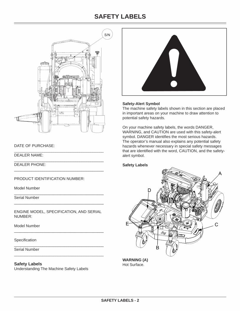
S/N
DATE OF PURCHASE:_________________________________________DEALER NAME:_________________________________________DEALER PHONE:_________________________________________
PRODUCT IDENTIFICATION NUMBER:
Model Number_________________________________________Serial Number_________________________________________
ENGINE MODEL, SPECIFICATION, AND SERIAL NUMBER:
Model Number_________________________________________
Specifi cation_________________________________________Serial Number_________________________________________
Safety LabelsUnderstanding The Machine Safety Labels
Safety-Alert SymbolThe machine safety labels shown in this section are placed in important areas on your machine to draw attention to potential safety hazards.
On your machine safety labels, the words DANGER, WARNING, and CAUTION are used with this safety-alert symbol. DANGER identifi es the most serious hazards.The operator’s manual also explains any potential safety hazards whenever necessary in special safety messages that are identifi ed with the word, CAUTION, and the safety-alert symbol.
Safety Labels
A
D
B
CE
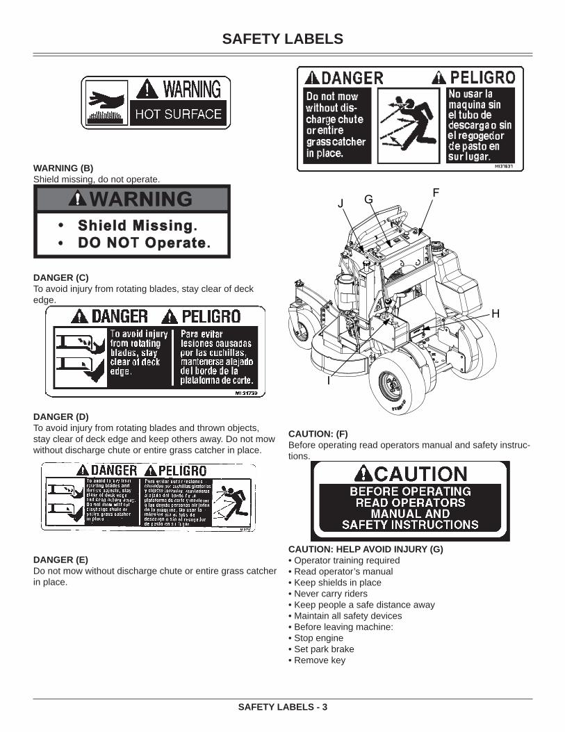
WARNING (A)Hot Surface.
SAFETY LABELS
SAFETY LABELS - 3
WARNING (B)Shield missing, do not operate.
WARNINGWARNINGShield MissingShield Missing.DO NODO NOT Operate Operate.
DANGER (C)To avoid injury from rotating blades, stay clear of deck edge.
DANGER (D)To avoid injury from rotating blades and thrown objects, stay clear of deck edge and keep others away. Do not mow without discharge chute or entire grass catcher in place.
DANGER (E)Do not mow without discharge chute or entire grass catcher in place.
G
H
F
I
J
CAUTION: (F)Before operating read operators manual and safety instruc-tions.
CAUTION: HELP AVOID INJURY (G)• Operator training required• Read operator’s manual• Keep shields in place• Never carry riders• Keep people a safe distance away• Maintain all safety devices• Before leaving machine:• Stop engine• Set park brake• Remove key

SAFETY
SAFETY - 4
CAUTION (H)Be safe! To avoid a fi re hazard remove all leaves, grass and debris from engine, hydro pumps and motors, pulleys, belts, hoses, engine deck and cutter deck.
DANGER/POISON (I)• Shield Eyes: Explosive gases can cause blindness or injury.• NO• Sparks• Flames• Smoking• Sulfuric acid can cause blindness or severe burns.• Flush eyes immediately with water. Get medical help fast.• Keep out of reach of children.• Do not tip.• Do not open battery.
WARNING (J)To avoid injury from tipover, drive across slopes, not up and down. If machine stops going uphill, stop blades and back down slowly.
Emission Control System Certifi cation LabelNOTE: Tampering with emission controls and components by unauthorized personnel may result in severe fi nes or penalties. Emission controls and components can only be adjusted by EPA and/or CARB authorized service centers. Contact your EverRide Equipment Retailer concerning emission controls and component questions.
The presence of an emissions label signifi es that the en-
gine has been certifi ed with the United States Environmen-tal Protection Agency (EPA) and/or California Air Resources Board (CARB).
The emissions warranty applies only to those engines marketed by EverRide that have been certifi ed by the EPA and/or CARB; and used in the United States and Canada in off-road mobile equipment.
Emission Compliance PeriodIf your engine has the emission compliance category listed on the emission control system certifi cation or air index label, this indicates the number of operating hours for which the engine has been certifi ed to meet EPA and/or CARB emission requirements. The following table provides the engine compliance period in hours associated with the category found on the certifi cation label.
Agency Category HoursEPA C 250EPA B 500EPA A 1000CARB Moderate 125CARB Intermediate 250CARB Extended 500
Certifi cationYour product has been tested and evaluated by the manu-facturer and conforms with American National Standard B-71.4, “Safety Specifi cations” for commercial turf care equipment.
SafetyOperator Training Required
Read the operator’s manual and other training mate-rial. If the operator or mechanic cannot read English, it is the owner’s responsibility to explain this material to them. This publication is available in other languages.Become familiar with the safe operation of the equip-ment, operator controls, and safety signs.All operators and mechanics should be trained. The owner of the machine is responsible for training the users.Never let children or untrained people operate or ser-vice the equipment. Local regulations may restrict the age of the operator.The owner/user can prevent and is responsible for accidents or injuries occurring to themselves, other people, or property.Operate the machine in an open, unobstructed area under the direction of an experienced operator.
PreparationEvaluate the terrain to determine what accessories and attachments are needed to properly and safely perform
•
•
•
•
•
•
•
SAFETY
SAFETY - 5
the job. Only use accessories and attachments ap-proved by the manufacturer.Wear appropriate clothing including hard hat, safety glasses and hearing protection. Long hair, loose cloth-ing or jewelry may get tangled in moving parts.Inspect the area where the equipment is to be used and remove all objects such as rocks, toys and wire which can be thrown by the machine.Use extra care when handling gasoline and other fuels. They are fl ammable and vapors are explosive.
a. Use only an approved container.b. Never remove gas cap or add fuel when engine
is running. Do not smoke.c. Never refuel or drain the machine indoors.
Check that the operator’s presence controls, safety switches and shields are attached and functioning properly. Do not operate unless they are functioning properly.
Operating SafelyNever run an engine in an enclosed area where dan-gerous carbon monoxide fumes can collect. Only operate in good light, keeping away from holes and hidden hazards.Be sure all drives are in neutral and parking brake is engaged before starting engine. Only start engine from the operator’s position. Use seat belts if provided.Slow down and use extra care on hillsides. Be sure to travel in the recommended direction on hillsides. For this machine, drive across hillsides, not up and down. Turf conditions can affect the machine’s stability. Use caution while operating near drop-offs.Slow down and use caution when making turns and when changing directions on slopes.Never raise deck with the blades running.Never operate with the PTO shield, or other guards, not securely in place. Be sure all interlocks are attached, adjusted properly, and functioning properly.Never operate with the discharge defl ector raised, removed or altered, unless using a grasscatcher. Do not operate mower without discharge chute or entire grasscatcher in place.Do not change the engine governor setting or overspeed the engine. Operating the engine at exces-sive speed can increase the hazard of personal injury.Stop on level ground, lower implements, disengage drives, engage parking brake, and shut off engine before leaving the operator’s position for any reason including emptying the grasscatchers or unclogging the chute.Stop equipment and inspect blades after striking ob-jects or if an abnormal vibration occurs. Make neces-sary repairs before resuming operations.Keep hands and feet away from the cutting units.Look behind and down before backing up to be sure of a clear path.Never carry passengers and keep pets and bystanders
•
•
•
•
•
•
•
•
•
••
•
•
•
•
••
•
away.Slow down and use caution when making turns and crossing roads and sidewalks. Stop blades if not mow-ing. Watch for traffi c when operating near or crossing roadways.Be aware of the mower discharge direction and do not point it at anyone.Do not operate the machine while under the infl uence of alcohol or drugs.Use care when loading or unloading the machine into or off of a trailer or truck.Use care when approaching blind corners, shrubs, trees, or other objects that may obscure vision.Inspect machine before you operate. Be sure hardware is tight. Repair or replace damaged, badly worn, or missing parts. Be sure guards and shields are in good condition and fastened in place. Make any necessary adjustments before you operate.Before using, always visually inspect to see that the blades, blade bolts and the mower assembly are not worn and damaged. Replace worn and damaged blades and bolts in sets to preserve balance.Keep safety labels visible when installing accessories and attachments.Do not wear radio or music headphones. Safe service and operation require your full attention.When machine is left unattended, stored, or parked, lower the mower deck unless a positive mechanical lock is used.
Using a Spark Arrestor
The engine in this machine is not equipped with a spark ar-restor muffl er. It is a violation of California Public Resource Code Section 4442 to use or operate this engine on or near any forest-covered, brush-covered or grass-covered land unless the exhaust system is equipped with a spark arres-tor meeting any applicable local or state laws. Other states or federal areas may have similar laws.
A spark arrestor for your machine may be available from your authorized dealer. An installed spark arrestor must be maintained in good working order by the operator.
Checking Mowing AreaEvaluate the terrain to determine what accessories and attachments are needed to properly and safely perform the job. Clear mowing area of objects that might be thrown. Keep people and pets out of mowing area.Study mowing area. Set up a safe mowing pattern. Do not mow where traction or stability is doubtful.Test drive area with mower lowered but not running. Slow down when you travel over rough ground.
•
•
•
•
•
•
•
•
•
•
•
•
•
•
SAFETY
SAFETY - 6
Parking Safely
Stop machine on a level surface, not on a slope.Disengage mower blades.Lock the park brake.Stop the engine.Remove the key.Wait for engine and all moving parts to stop before you leave the operator’s station.Close fuel shut-off valve, if your machine is equipped.Disconnect the negative battery cable or remove the spark plug wire (for gasoline engines) before servicing the machine.
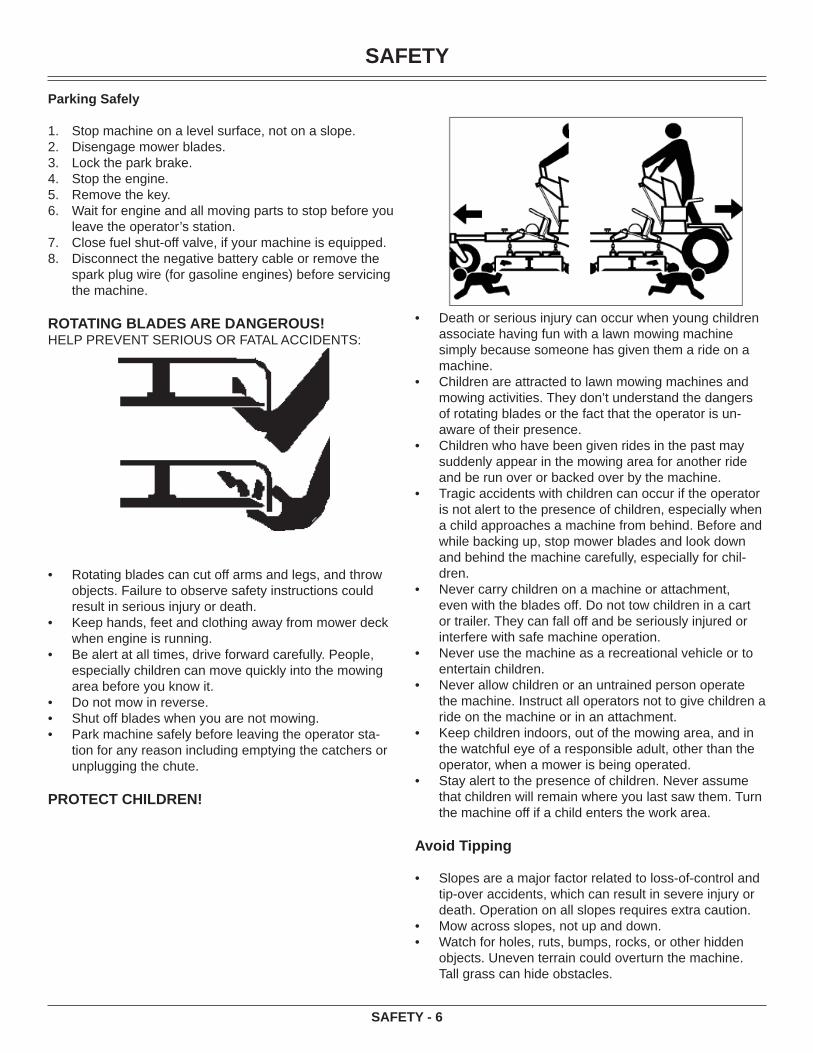
ROTATING BLADES ARE DANGEROUS!HELP PREVENT SERIOUS OR FATAL ACCIDENTS:
Rotating blades can cut off arms and legs, and throw objects. Failure to observe safety instructions could result in serious injury or death.Keep hands, feet and clothing away from mower deck when engine is running.Be alert at all times, drive forward carefully. People, especially children can move quickly into the mowing area before you know it.Do not mow in reverse.Shut off blades when you are not mowing.Park machine safely before leaving the operator sta-tion for any reason including emptying the catchers or unplugging the chute.
PROTECT CHILDREN!
1.2.3.4.5.6.
7.8.
•
•
•
•••
Death or serious injury can occur when young children associate having fun with a lawn mowing machine simply because someone has given them a ride on a machine.Children are attracted to lawn mowing machines and mowing activities. They don’t understand the dangers of rotating blades or the fact that the operator is un-aware of their presence.Children who have been given rides in the past may suddenly appear in the mowing area for another ride and be run over or backed over by the machine.Tragic accidents with children can occur if the operator is not alert to the presence of children, especially when a child approaches a machine from behind. Before and while backing up, stop mower blades and look down and behind the machine carefully, especially for chil-dren.Never carry children on a machine or attachment, even with the blades off. Do not tow children in a cart or trailer. They can fall off and be seriously injured or interfere with safe machine operation.Never use the machine as a recreational vehicle or to entertain children.Never allow children or an untrained person operate the machine. Instruct all operators not to give children a ride on the machine or in an attachment.Keep children indoors, out of the mowing area, and in the watchful eye of a responsible adult, other than the operator, when a mower is being operated.Stay alert to the presence of children. Never assume that children will remain where you last saw them. Turn the machine off if a child enters the work area.
Avoid Tipping
Slopes are a major factor related to loss-of-control and tip-over accidents, which can result in severe injury or death. Operation on all slopes requires extra caution. Mow across slopes, not up and down.Watch for holes, ruts, bumps, rocks, or other hidden objects. Uneven terrain could overturn the machine. Tall grass can hide obstacles.
•
•
•
•
•
•
•
•
•
•
••

SAFETY
SAFETY - 7
Choose a low ground speed so you will not have to stop or shift while on a slope.Do not mow or operate machine on wet grass. Tires may lose traction. • • • Tires may lose traction on slopes even though the brakes are functioning properly.Avoid starting, stopping or turning on a slope. If the tires lose traction, disengage the blades and proceed slowly, straight down the slope.Keep all movement on slopes slow and gradual. Do not make sudden changes in speed or direction, which could cause the machine to roll over.Use extra care while operating machine with grass-catchers or other attachments, they can affect stability of the machine. Do not use on steep slopes.Do not mow near drop-offs, ditches, embankments, or bodies of water. The machine could suddenly roll over if a wheel goes over the edge or the edge caves in.Follow the manufacturer’s recommendations for wheel weights or counterweights for added stability when operating on slopes or using front or rear mounted at-tachments. Remove weights when not required.Drive machine very slowly and avoid quick stops when attachment is removed.Transport machine with decks lowered to improve stability.
Keep Riders OffOnly allow the operator on the machine. Keep riders off.Riders on the machine or attachment may be struck by foreign objects or thrown off the machine causing seri-ous injury.Riders obstruct the operator’s view resulting in the ma-chine being operated in an unsafe manner.
Avoid High Pressure FluidsHydraulic hoses and lines can fail due to physical dam-age, kinks, age, and exposure. Check hoses and lines regularly. Replace damaged hoses and lines.Hydraulic fl uid connections can loosen due to physical damage and vibration. Check connections regularly. Tighten loose connections.Escaping fl uid under pressure can penetrate the skin causing serious injury. Avoid the hazard by relieving pressure before disconnecting hydraulic or other lines. Tighten all connections before applying pressure.Search for leaks with a piece of cardboard. Protect hands and body from high pressure fl uids.If an accident occurs, see a doctor immediately. Any fl uid injected into the skin must be surgically removed within a few hours or gangrene may result. Doctors unfamiliar with this type of injury should reference a knowledgeable medical source.
Checking Wheel HardwareA serious accident could occur causing serious injury if wheel hardware is not tight.Check wheel hardware tightness often during the fi rst
•
•
•
•
•
•
•
•
•
•
•
•
•
•
•
•
•
•
•
100 hours of operation.Wheel hardware must be tightened to specifi ed torque using the proper procedure anytime it is loosened.
Wear Appropriate ClothingAlways wear safety goggles, or safety glasses with side shields, and a hard hat when operating the machine.Wear close fi tting clothing and safety equipment ap-propriate for the job.While mowing, always wear substantial footwear and long trousers. Do not operate the equipment when barefoot or wearing open sandals.Wear a suitable protective device such as earplugs. Loud noise can cause impairment or loss of hearing.
Maintenance and StorageNever operate machine in a closed area where danger-ous carbon monoxide fumes can collect.Disengage drives, lower implement, lock parking brake, stop engine and remove key or disconnect spark plug (for gas engines). Wait for all movement to stop before adjusting, cleaning or repairing.Clean grass and debris from cutting units, drives, muf-fl ers, and engine to help prevent fi res. Clean up oil or fuel spillage.Let engine cool before storing and do not store near fl ame.Shut off fuel while storing or transporting. Do not store fuel near fl ames or drain indoors.Park machine on level ground. Never allow untrained personnel to service machine. Understand service procedure before doing work.Use jack stands or lock service latches to support com-ponents when required. Securely support any machine elements that must be raised for service work.Before servicing machine or attachment, carefully release pressure from any components with stored energy, such as hydraulic components or springs.Release hydraulic pressure by lowering attachment or cutting units to the ground or to a mechanical stop and move hydraulic control levers back and forth.Disconnect battery or remove spark plug (for gas engines) before making any repairs. Disconnect the negative terminal fi rst and the positive last. Reconnect positive fi rst and negative last.Use care when checking blades. Wrap the blades or wear gloves, and use caution when servicing them. Only replace blades. Never straighten or weld them.Keep hands, feet, clothing, jewelry and long hair away from moving parts. If possible, do not make adjust-ments with the engine running.Charge batteries in an open well ventilated area, away from spark and fl ames. Unplug charger before con-necting or disconnecting from battery. • Wear protective clothing and use insulated tools.Keep all parts in good working condition and all hard-ware tightened. Replace all worn or damaged decals.Check grass catcher components and the discharge guard frequently and replace with manufacturer’s rec-
•
•
•
•
•
•
•
•
•
•
•
•
•
•
•
•
•
•
•
•
SAFETY
SAFETY - 8
ommended parts, when necessary. Grass catcher com-ponents are subject to wear, damage, and deterioration which could expose moving parts or allow objects to be thrown.Keep all nuts and bolts tight, especially blade attach-ment bolts, to be sure the equipment is in safe working condition.Check brake operation frequently. Adjust and service as required.On multi-bladed machines, take care as rotating one blade can cause other blades to rotate.
Prevent FiresRemove grass and debris from engine compartment and muffl er area, before and after operating machine, especially after mowing or mulching in dry conditions.Empty the grass catcher completely before storing.Always shut off fuel when storing or transporting ma-chine, if the machine has a fuel shutoff.Do not store machine near an open fl ame or source of ignition, such as a water heater or furnace.Check fuel lines, tank, cap, and fi ttings frequently for cracks or leaks. Replace if necessary.
Tire SafetyExplosive separation of a tire and rim parts can cause seri-ous injury or death:
Do not attempt to mount a tire without the proper equip-ment and experience to perform the job. Always maintain the correct tire pressure. Do not infl ate the tires above the recommended pressure. Never weld or heat a wheel and tire assembly. The heat can cause an increase in air pressure resulting in a tire explosion. Welding can structurally weaken or deform the wheel.When infl ating tires, use a clip-on chuck and extension hose long enough to allow you to stand to one side and NOT in front of or over the tire assembly.Check tires for low pressure, cuts, bubbles, damaged rims or missing lug bolts and nuts.
Handling Fuel SafelyTo avoid personal injury or property damage, use extreme care in handling fuel. Fuel is extremely fl am-mable and fuel vapors are explosive:
Extinguish all cigarettes, cigars, pipes, and other sources of ignition.Use only an approved fuel container. Use only non-metal, portable fuel containers approved by the Under-writer’s Laboratory (U.L.) or the American Society for Testing & Materials (ASTM). If using a funnel, make sure it is plastic and has no screen or fi lter.Never remove the fuel tank cap or add fuel with the engine running. Allow engine to cool before refueling.Never add fuel to or drain fuel from the machine in-doors. Move machine outdoors and provide adequate ventilation.Clean up spilled fuel immediately. If fuel is spilled on
•
•
•
•
••
•
•
•
•
•
•
•
•
•
•
•
clothing, change clothing immediately. If fuel is spilled near machine, do not attempt to start the engine but move the machine away from the area of spillage. Avoid creating any source of ignition until fuel vapors have dissipated.Never store the machine or fuel container where there is an open fl ame, spark, or pilot light such as on a wa-ter heater or other appliance.Prevent fi re and explosion caused by static electric dis-charge. Static electric discharge can ignite fuel vapors in an ungrounded fuel container.Never fi ll containers inside a vehicle or on a truck or trailer bed with a plastic liner. Always place containers on the ground away from your vehicle before fueling.
Remove fuel-powered equipment from the truck or trailer and refuel it on the ground. If this is not possible, then refuel such equipment with a portable container, rather than from a fuel dispenser nozzle.Keep the nozzle in contact with the rim of the fuel tank or container opening at all times until the fueling is complete. Do not use a nozzle lock-open device.Never overfi ll fuel tank. Replace fuel tank cap and tighten securely.Replace all fuel container caps securely after use.For gasoline engines, do not use gas with methanol. Methanol is harmful to your health and to the environ-ment.
Handling Waste Product and Chemicals Waste products, such as, used oil, fuel, coolant, brake fl uid, and batteries, can harm the environment and people:Do not use beverage containers for waste fl uids - someone may drink from them.See your local Recycling Center or authorized dealer to learn how to recycle or get rid of waste products.A Material Safety Data Sheet (MSDS) provides spe-cifi c details on chemical products: physical and health hazards, safety procedures, and emergency response techniques. The seller of the chemical products used with your machine is responsible for providing the MSDS for that product.
Operating Daily Operating Checklist Make sure all necessary guards and shields are safely
and securely attached. Check for loose, missing, or damaged parts.
•
•
•
•
•
•
••
•
•
•
•
OPERATING
OPERATING - 9
Remove mower deck belt shields. Clean grass and debris from belt area.
Remove grass and debris from machine and mower deck.
Remove grass and debris from operator station foot plate, pump drive belt compartment, hydraulic pump and pump mounting plate.
Test park brake. Test safety systems. Check battery. Check for oil leaks. Check engine oil and hydraulic oil levels. Check all belts for damage or cracking. Check engine air fi lter. Check mower level. Adjust cutting height if necessary. Check wheel bolt torque. Tighten if necessary. Check tire air pressure. Check tires for damage or
cracking. Check and adjust speed control linkages and lock.
Avoid Damage to Plastic and Painted SurfacesDo not wipe plastic parts unless rinsed fi rst. Insect repellent spray may damage plastic and painted surfaces. Do not spray insect repellent near machine.Be careful not to spill fuel on machine. Fuel may dam-age surface. Wipe up spilled fuel immediately.Prolonged exposure to sunlight will damage the hood surface.
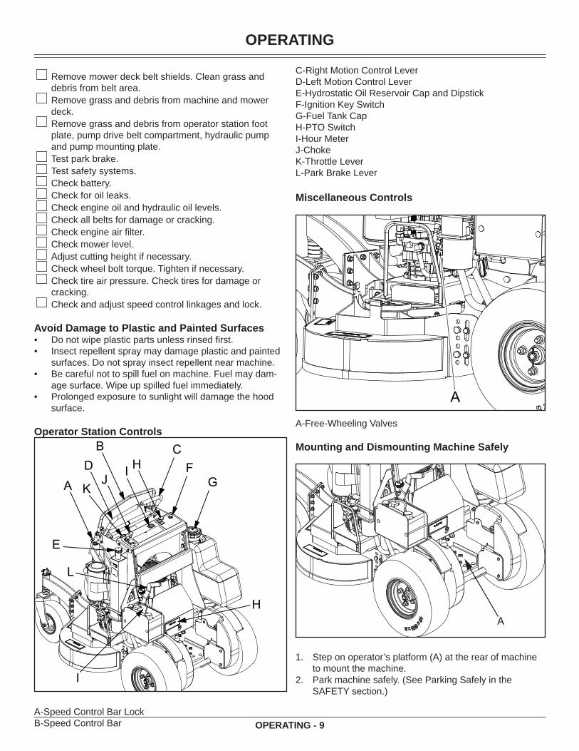
Operator Station ControlsB
H
F
I
A
E
CD
GHI
JK
L
A-Speed Control Bar LockB-Speed Control Bar
••
•
•
C-Right Motion Control LeverD-Left Motion Control LeverE-Hydrostatic Oil Reservoir Cap and DipstickF-Ignition Key SwitchG-Fuel Tank CapH-PTO SwitchI-Hour MeterJ-ChokeK-Throttle LeverL-Park Brake Lever
Miscellaneous Controls
AA-Free-Wheeling Valves
Mounting and Dismounting Machine Safely
A
Step on operator’s platform (A) at the rear of machine to mount the machine.Park machine safely. (See Parking Safely in the SAFETY section.)
1.
2.

OPERATING
OPERATING - 10
Step off operator’s platform to dismount machine.Keep operator’s platform and suspension springs clean and free of debris.
Raising and Lowering Thigh PadPark machine safely. (See Parking Safely in the SAFETY section.)
A
Adjust the pad (A) as required by lifting or lowering the pad to where it is comfortable.
Adjusting Cutting Height
Cutting height can be adjusted from approximately 38-114 MM. (1-1/2 - 4-1/2 in.). Each hole adjusts the height of cut (HOC) in 12 MM. (1/2 in.) increments.
CAUTION: Avoid injury! Before adjusting cut-ting height, stop engine and lock the park brake.
Check tire pressure. Infl ate front caster wheels to 138-173 Kpa (20-25 psi). Infl ate rear tires to 69-83 Kpa (10-12 psi).
CAUTION: Avoid injury! Machine must be safely supported on jack stands before remov-ing or installing wheels. Do not use a hoist or fl oor jack to support the machine.
Using a suitable lifting device, lift the rear of the ma-chine.
3.4.
1.
2.
1.
2.
A
B
C
Loosen bolts (A).Loosen and remove bolts (B).Move deck (C) up or down to desired height and tighten bolts (A) to 47-54 N•m (35-40 lb-ft).Insert bolts (B) into holes and tighten to 95-108 N•m (70-80 lb-ft).Remove lynch pin (D) and spacer bushing (E).
D
EF
GH
Caster MountingIn Upper Positio
IMPORTANT: Do not allow washer (G) to set on caster yoke. It must be on top of height-of-cut spacer bushings (H).
NOTE: Adjust caster wheel spacers to keep mower deck tilted slightly down at the front.
Adjust caster wheel spacers (F) to compensate front HOC accordingly.
Setting Cutting Height NOTE: Before setting cut height, ensure the
tires are all set at the correct tire pressures.
3.4.5.
6.
7.
8.

OPERATING
OPERATING - 11
Caster to deck mounting positionCaster to deck mounting - Upper PositonRear of Deck Front CastersRear Deck Nominal Height C-Spacers C-Spacers Height of Cut Deck RakeHole Position Top Bottom (inches) (inches)1 4.5 NA1 4.51 4.5
2 3.5 0 4 3.5 02 3.5 1 3 3 0.52 3.5 2 2 2.5 1
3 2.5 2 2 2.5 03 2.5 3 1 2 0.53 2.5 4 0 1.5 1
Caster to deck mounting - Lower PositonRear of Deck Front CastersRear Deck Nominal Height C-Spacers C-Spacers Height of Cut Deck RakeHole Position Top Bottom (inches) (inches)1 4.5 1 3 4.5 01 4.5 2 2 4 0.51 4.5 3 1 3.5 1
2 3.5 3 1 3.5 02 3.5 4 0 3 0.52 3.5 NA
3 2.53 2.53 2.5
Upper Positon
HOLE LOCATIONSTo adjust the rear height of cut, use the chart above and match the hole locations on the chart up to the hole loca-tions on the picture.
To adjust the front height of cut, use the chart above and in-sert the number of C-spacers to correspond to the number on the chart to achieve the height of cut you desire. NOTE: Rake is described as the amount that the rear of the deck is above the front of the deck. Your best cut will occur when you have at least some rake on the deck.
OPERATING
OPERATING - 12
Testing Safety Systems
CAUTION: Avoid injury! Engine exhaust fumes contain carbon monoxide and can cause serious illness or death.
Move the machine to an outside area before running the engine.
Do not run an engine in an enclosed area without adequate ventilation.
• Connect a pipe extension to the engine exhaust pipe to direct the exhaust fumes out of the area.
• Allow fresh outside air into the work area to clear the exhaust fumes out.
The safety systems installed on your machine should be checked before each machine use. Be sure you have read the machine operator manual and are completely familiar with the operation of the machine before performing these safety system checks.
Use the following checkout procedures to check for normal operation of machine.
If there is a malfunction during one of these procedures, do not operate machine. See your authorized dealer for service.
Perform these tests in a clear open area. Keep bystanders away.
Testing PTO SwitchStand on operator’s platform with motion control levers in the neutral position.Lock park brake.Pull PTO switch up to engage.Turn key switch to the start position.
Result: The engine must not crank.
Testing Park Brake SwitchPush PTO switch down to disengage.Unlock park brake.Turn key switch to the start position.
Result: The engine must not crank.
Testing Neutral Switch (Start)Lock park brake.Push PTO switch down to disengage.Push one motion control lever forward.Turn key switch to the start position.
Result: The engine must not crank.
1.
2.3.4.
1.2.3.
1.2.3.4.
Testing Neutral Switch (Run)Lock park brake.Push PTO switch down to disengage.Start engine.Push one motion control lever forward.Repeat procedure using the other lever.Repeat procedure pushing each motion control lever rearward.
Result: The engine must stop when either lever is moved from neutral position.
Testing Operator Presence SwitchNOTE: Ensure OPC switch bracket is depressed when standing on operator’s station.
Stand on operator’s platform with motion control levers in the NEUTRAL position.Start engine.Unlock park brake.Step completely off operator’s platform.
Result: The engine must stop.NOTE: Ensure OPC switch bracket is depressed when standing on operator’s station.
Stand on operator’s platform with motion control levers in the NEUTRAL position and start engine.
CAUTION: Avoid injury! Thrown objects can be dangerous. Before operating the attachment:
Clear area of bystanders, especially children.Pick up objects which may be thrown by the attachment.
Pull PTO switch up to engage.Step completely off operator’s platform.
Result: The engine must stop.
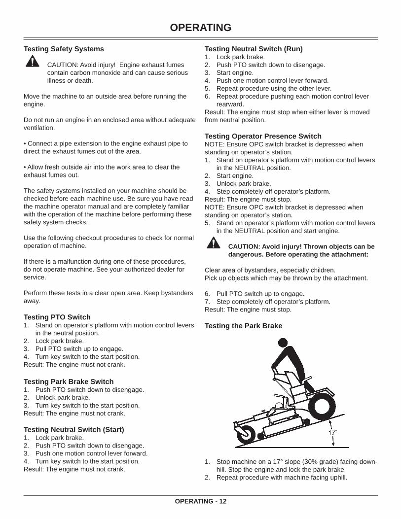
Testing the Park Brake
Stop machine on a 17° slope (30% grade) facing down-hill. Stop the engine and lock the park brake.Repeat procedure with machine facing uphill.
1.2.3.4.5.6.
1.
2.3.4.
5.
6.7.
1.
2.

OPERATING
OPERATING - 13
Result: Park brake must hold the machine stationary. (Ma-chine should move no more that 61cm (24 in.) in one hour.) If machine moves more than that, brakes need to be adjust-ed. See your authorized dealer or refer to Adjusting Park Brake in the SERVICE STEERING AND BRAKES section.
Using Park Brake
Locking Park Brake
A
Raise park brake lever (A) to lock park brake.Unlocking Park Brake:Lower park brake lever (A) to unlock park brake. Using the PTO
Engage PTO:Stand on operator’s platform with motion control levers in the neutral position.Start engine.Release park brake.Move throttle lever to the 1/2 to 3/4 fast position.
A
Pull PTO knob (A) up to engage mower deck.
1.
2.3.4.
5.
Move throttle lever forward to the fast position for mow-ing.
Disengage PTO:Push PTO knob (A) down.Set park brake.
Using the Throttle
A
B
DC
Push throttle lever (A) forward to the fast position (B) when mowing.Move throttle lever (A) to the half fast position (C) when starting and warming the engine.Pull throttle lever (A) backward to the slow position (D) to idle engine. Do not run engine at slow idle any lon-ger than necessary for cooldown after mowing.
Using the Hourmeter NOTE: The machine is equipped with an electric start. The hourmeter will continue to run with the key switch in the run position.
A
Hourmeter (A) shows number of hours the machine has been operated.
6.
1.2.
•
•
•
•
OPERATING
OPERATING - 14
Use hourmeter and SERVICE INTERVAL section to determine when machine needs service.
Using the Motion Control LeversThe functions of the motion control levers are:
CAUTION: Avoid injury! Learn use of the motion control levers and practice at half throttle until becoming profi cient and comfortable with the operation of the machine.
Do not move motion control levers from forward to reverse or reverse to forward position rapidly. Sudden direction changes could cause loss of control or damage the machine.
• Steering.• Acceleration.• Deceleration.
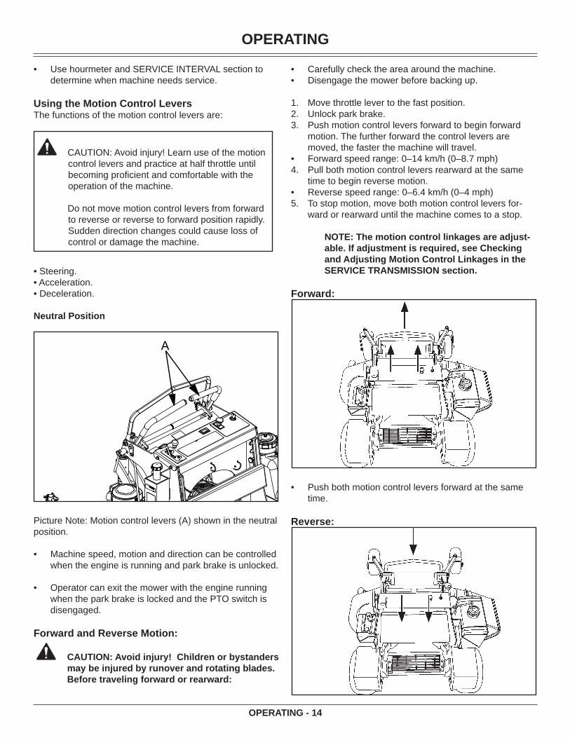
Neutral Position
A
Picture Note: Motion control levers (A) shown in the neutral position.
Machine speed, motion and direction can be controlled when the engine is running and park brake is unlocked.
Operator can exit the mower with the engine running when the park brake is locked and the PTO switch is disengaged.
Forward and Reverse Motion:
CAUTION: Avoid injury! Children or bystanders may be injured by runover and rotating blades. Before traveling forward or rearward:
•
•
•
Carefully check the area around the machine.Disengage the mower before backing up.
Move throttle lever to the fast position.Unlock park brake.Push motion control levers forward to begin forward motion. The further forward the control levers are moved, the faster the machine will travel.Forward speed range: 0–14 km/h (0–8.7 mph)Pull both motion control levers rearward at the same time to begin reverse motion.Reverse speed range: 0–6.4 km/h (0–4 mph)To stop motion, move both motion control levers for-ward or rearward until the machine comes to a stop.
NOTE: The motion control linkages are adjust-able. If adjustment is required, see Checking and Adjusting Motion Control Linkages in the SERVICE TRANSMISSION section.
Forward:
Push both motion control levers forward at the same time.
Reverse:
••
1.2.3.
•4.
•5.
•
OPERATING
OPERATING - 15
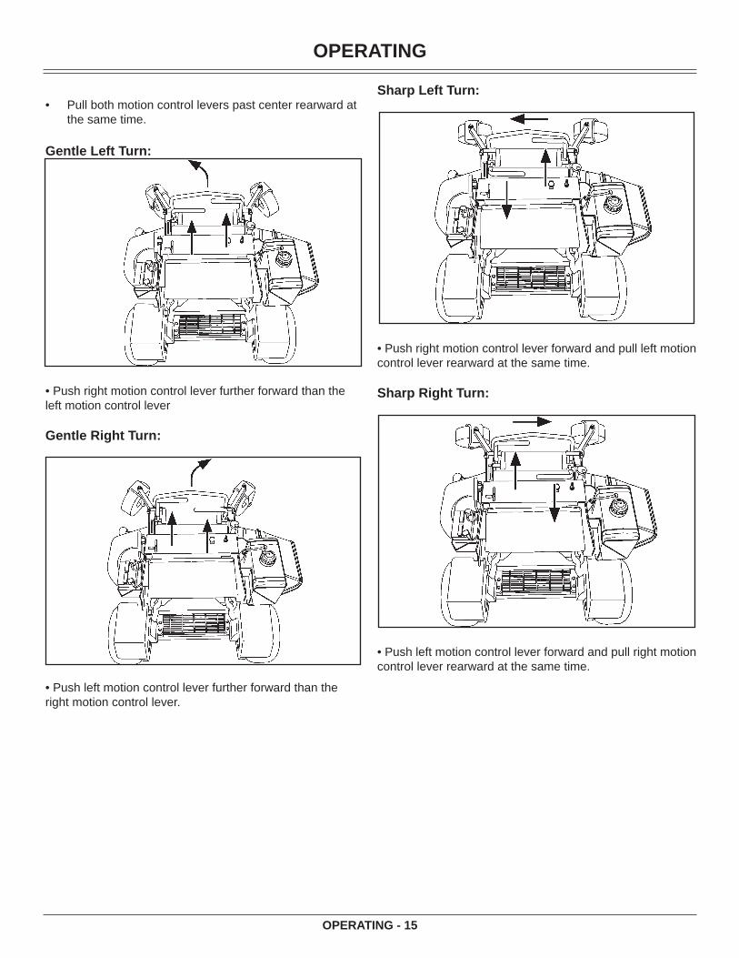
Pull both motion control levers past center rearward at the same time.
Gentle Left Turn:
• Push right motion control lever further forward than the left motion control lever
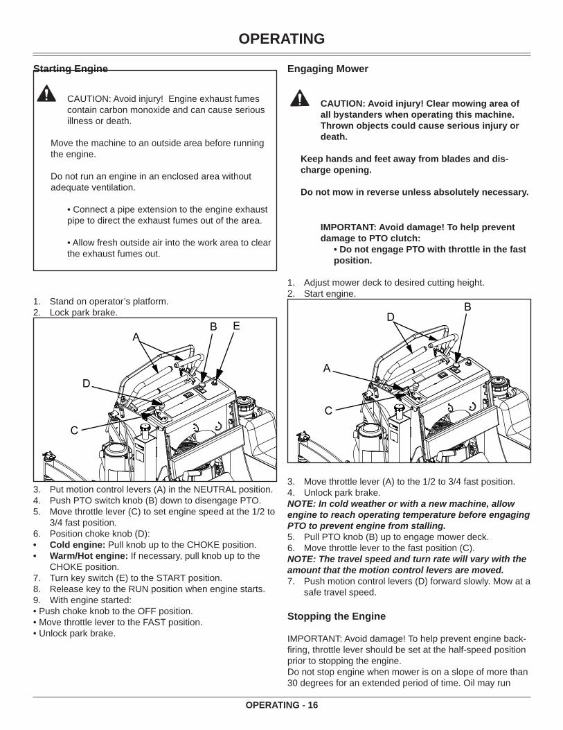
Gentle Right Turn:
• Push left motion control lever further forward than the right motion control lever.
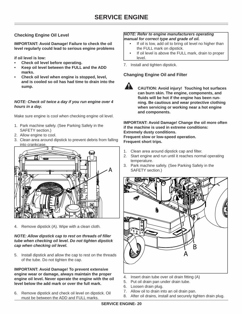
•Sharp Left Turn:
• Push right motion control lever forward and pull left motion control lever rearward at the same time.
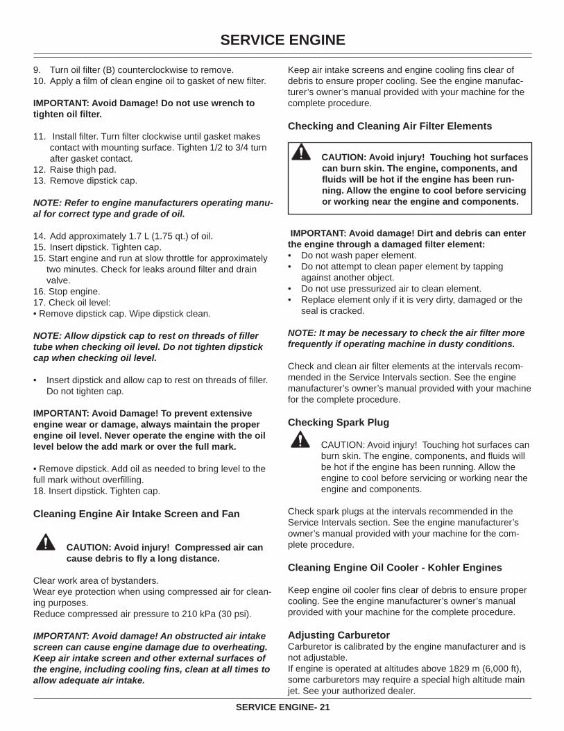
Sharp Right Turn:
• Push left motion control lever forward and pull right motion control lever rearward at the same time.
OPERATING
OPERATING - 16
Starting Engine
CAUTION: Avoid injury! Engine exhaust fumes contain carbon monoxide and can cause serious illness or death.
Move the machine to an outside area before running the engine.
Do not run an engine in an enclosed area without adequate ventilation.
• Connect a pipe extension to the engine exhaust pipe to direct the exhaust fumes out of the area.
• Allow fresh outside air into the work area to clear the exhaust fumes out.
Stand on operator’s platform.Lock park brake.
D
B
C
AE
Put motion control levers (A) in the NEUTRAL position.Push PTO switch knob (B) down to disengage PTO.Move throttle lever (C) to set engine speed at the 1/2 to 3/4 fast position.Position choke knob (D):Cold engine: Pull knob up to the CHOKE position.Warm/Hot engine: If necessary, pull knob up to the CHOKE position.Turn key switch (E) to the START position.Release key to the RUN position when engine starts.With engine started:
• Push choke knob to the OFF position.• Move throttle lever to the FAST position.• Unlock park brake.
1.2.
3.4.5.
6.••
7.8.9.
Engaging Mower
CAUTION: Avoid injury! Clear mowing area of all bystanders when operating this machine. Thrown objects could cause serious injury or death.
Keep hands and feet away from blades and dis-charge opening.
Do not mow in reverse unless absolutely necessary.
IMPORTANT: Avoid damage! To help prevent damage to PTO clutch:
• Do not engage PTO with throttle in the fast position.
Adjust mower deck to desired cutting height.Start engine.
A
B
C
D
Move throttle lever (A) to the 1/2 to 3/4 fast position.Unlock park brake.
NOTE: In cold weather or with a new machine, allow engine to reach operating temperature before engaging PTO to prevent engine from stalling.
Pull PTO knob (B) up to engage mower deck.Move throttle lever to the fast position (C).
NOTE: The travel speed and turn rate will vary with the amount that the motion control levers are moved.
Push motion control levers (D) forward slowly. Mow at a safe travel speed.
Stopping the Engine
IMPORTANT: Avoid damage! To help prevent engine back-fi ring, throttle lever should be set at the half-speed position prior to stopping the engine.Do not stop engine when mower is on a slope of more than 30 degrees for an extended period of time. Oil may run
1.2.
3.4.
5.6.
7.

OPERATING
OPERATING - 17
through valve train into carburetor and muffl er.
Lock park brake.Reduce engine speed to half-throttle.Turn key switch to STOP position (C).Remove key.
Using Pump Free-Wheel Valves
CAUTION: Avoid injury! With the free-wheeling valve open, the machine will have unrestricted motion.
• The machine may free-wheel out of control if the free-wheeling valve is opened with the machine on an incline.
• Park the machine on a level surface before opening the free-wheeling valve.
IMPORTANT: Avoid Damage! Transmission damage may occur if the machine is towed or moved incorrectly:
Move machine by hand only.Do not use another vehicle to move machine.Do not tow machine.
NOTE: The pump free-wheel valves must be turned fully clockwise (closed) during normal machine opera-tion.
When the machine needs to be moved without starting the engine, use the pump free-wheel valves:
Lock park brake.
CA
B
Turn both pump free-wheel valves (C) counterclock-wise approximately one full turn (open position).Unlock park brake.
1.2.3.4.
•••
1.
2.
3.
Push machine to desired location. Due to hydraulic system drag, machine will move slowly.Turn pump free-wheel valves (C) on both pumps one full turn clockwise (closed position). Tighten valves to 11 N•m (100 lb-in.).Lock park brake.
Transporting Machine on a Trailer
Use a heavy-duty trailer to transport your machine. Trailer must have signs and lights required by law.
CAUTION: Avoid injury! Use extra care when load-ing or unloading the machine into a trailer or truck.
• Close fuel shut-off valve, if your machine is equipped.
Raise mower deck to the transport position.Drive machine onto a trailer.Stop engine and lock park brake.Remove key.Fasten machine to trailer with heavy-duty straps, chains or cables. Both front and rear straps must be directed downward and outward from machine.
Mowing Tips
• Mow grass with throttle lever in the full fast position.• Cut grass when it is dry.• Keep mower deck and discharge chute clean.• Mow with sharp blades.• Properly level mower deck for a smooth cut.• Mow grass high and often.• Use a travel speed that fi ts the conditions:• Mow tall or wet grass twice. Cut grass at half desired
height – then cut at desired height.• Travel slow when mowing tall, thick or wet grass.• Avoid damaging grass by slipping or skidding machine
drive wheels. Practice smooth control lever movements.• When performing sharp turns, do not allow inside ma-
chine drive wheel to stop and twist on grass.
Mowing Travel Speeds
Use slow travel speeds for:• Slopes.• Trimming.• Close quarters.• Tall grass.
Use faster travel speeds for:Normal mowing on level ground.
4.
5.
6.
1.2.3.4.5.
•

SERVICE INTERVALS
SERVICE INTERVALS- 18
CAUTION: Avoid injury! Help prevent serious injury. Keep hands and feet away from blades and the discharge opening.
• Do not step on either side of the mower deck when mounting and dismounting the machine. Mount and dismount the machine using the front foot plate.
Park machine on a hard, level surface.Disengage PTO.Move motion control levers to the neutral position.Lock park brake.Stop engine and remove key. Wait for mower blades to stop turning before leaving operator’s position.
Service IntervalsServicing Your Machine
IMPORTANT: Avoid Damage! Operating in extreme condi-tions may require more frequent service intervals:
• Engine components may become dirty or plugged when operating in extreme heat, dust or other se-vere conditions.
• Engine oil may lose effi ciency if vehicle is operated constantly at slow or low engine speeds or with frequent short trips.
Please use the following timetables to perform routine maintenance on your machine.
Servicing Engine
See engine manufacturer’s owner’s manual provided with your machine for engine service information.
Break-In (After First 10 Hours)• Check air pressure in tires.• Check wheel bolt torque.• Check and adjust park brake.• Change engine oil and fi lter.• Check mower deck drive belt tension.• Check hydraulic pump drive belt.• Check transmission neutral adjustment.
Every 40 Hours• Check air pressure in tires.• Check wheel bolt torque.• Check and adjust park brake.• Change engine oil and fi lter.• Check foam and paper air cleaner elements.
1.2.3.4.5.
• Clean engine shrouds as needed.• Lubricate front caster spindles and wheels.• Lubricate mower deck idler pivot.• Check mower deck drive belt tension.• Lubricate hydraulic pump idler pivot.• Check hydraulic pump drive belt.• Check hydraulic fl uid level.• If operating machine in extremely dusty or dirty conditions:
• Clean behind engine shrouds and exposed fi ns.• Remove screws on blower fan screen and clean
behind.
Every 100 Hours• Lubricate mower deck spindles.• Clean and gap spark plugs.• Check hydraulic pump drive belt.• Clean behind engine shrouds and exposed fi ns.• Remove screws on blower fan screen and clean behind.
Every 500 Hours• Change hydraulic oil and fi lter.
Yearly • Change fuel fi lter.• Clean battery.• Change engine oil and fi lter at least once per season.• Change hydraulic oil and fi lter at least once per season.• Replace spark plugs.
Service LubricationGrease
IMPORTANT: Avoid Damage! The recommended grease is effective within an average air temperature range of -29 to 135 degrees C (-20 to 275 degrees F).
IMPORTANT: Avoid Damage! Use only NLGI No. 2 lithium based grease.
If operating outside that temperature range, contact your servicing dealer for a special-use grease.
Use a general all-purpose grease with an NLGI grade No.2 rating.
Wet or high speed conditions may require use of a special-use grease. Contact your Servicing dealer for information.Lubricating Front Caster Spindles and Wheels
CAUTION: Avoid injury! Fingers or loose clothing can get caught in rotating parts. Stop engine and wait for all moving parts to stop before servicing.
•

SERVICE ENGINE
SERVICE ENGINE- 19
A
B
• Lubricate two spindle grease fi ttings (A) and two wheel grease fi ttings (B).
Lubricating Pump Idler Pivot
A
Lubricate one pump idler pivot grease fi tting (A). Lubri-cate either the fi tting on the top of the engine bed or the one under the pump shield.
•
Lubricating Mower Deck Spindles
A
B
• Lubricate three mower deck spindle grease fi ttings (A).
Lubricating Mower Deck Idler Pivot
• Lubricate one deck idler pivot grease fi tting (B).
Service Engine Avoid Fumes
CAUTION: Avoid injury! Engine exhaust fumes contain carbon monoxide and can cause seri-ous illness or death.
Move the machine to an outside area before running the engine.
Do not run an engine in an enclosed area with-out adequate ventilation.
• Connect a pipe extension to the engine ex-haust pipe to direct the exhaust fumes out of the area.
• Allow fresh outside air into the work area to clear the exhaust fumes out.
Engine Oil Use oil viscosity based on the expected air temperature range during the period between oil changes.
Use oil that meets the following specifi cation:• See the engine manufacturer’s owner’s manual provided
with your machine for the correct specifi cations.
SERVICE ENGINE
SERVICE ENGINE- 20
Checking Engine Oil Level
IMPORTANT: Avoid Damage! Failure to check the oil level regularly could lead to serious engine problems
if oil level is low:Check oil level before operating.Keep oil level between the FULL and the ADD marks.Check oil level when engine is stopped, level, and is cooled so oil has had time to drain into the sump.
••
•
NOTE: Check oil twice a day if you run engine over 4 hours in a day.
Make sure engine is cool when checking engine oil level.
1. Park machine safely. (See Parking Safely in the SAFETY section.)
2. Allow engine to cool.3. Clean area around dipstick to prevent debris from falling
into crankcase.
Remove dipstick (A). Wipe with a clean cloth.
NOTE: Allow dipstick cap to rest on threads of fi ller tube when checking oil level. Do not tighten dipstick cap when checking oil level.
Install dipstick and allow the cap to rest on the threads of the tube. Do not tighten the cap.
IMPORTANT: Avoid Damage! To prevent extensive engine wear or damage, always maintain the proper engine oil level. Never operate the engine with the oil level below the add mark or over the full mark.
Remove dipstick and check oil level on dipstick. Oil must be between the ADD and FULL marks.
4.
5.
6.
NOTE: Refer to engine manufacturers operating manual for correct type and grade of oil.
If oil is low, add oil to bring oil level no higher than the FULL mark on dipstick.If oil level is above the FULL mark, drain to proper level.
•
•
Install and tighten dipstick.
Changing Engine Oil and Filter
CAUTION: Avoid injury! Touching hot surfaces can burn skin. The engine, components, and fl uids will be hot if the engine has been run-ning. Be cautious and wear protective clothing when servicing or working near a hot engine and components.
IMPORTANT: Avoid Damage! Change the oil more often if the machine is used in extreme conditions:Extremely dusty conditions.Frequent slow or low-speed operation.Frequent short trips.
Clean area around dipstick cap and fi lter.Start engine and run until it reaches normal operating temperature.Park machine safely. (See Parking Safely in the SAFETY section.)
Insert drain tube over oil drain fi tting (A)Put oil drain pan under drain tube.Loosen drain plug.Allow oil to drain into an oil drain pan.After oil drains, install and securely tighten drain plug.
7.
1.2.
3.
4.5.6.7.8.
SERVICE ENGINE
SERVICE ENGINE- 21
Turn oil fi lter (B) counterclockwise to remove.Apply a fi lm of clean engine oil to gasket of new fi lter.
IMPORTANT: Avoid Damage! Do not use wrench to tighten oil fi lter.
Install fi lter. Turn fi lter clockwise until gasket makes contact with mounting surface. Tighten 1/2 to 3/4 turn after gasket contact.Raise thigh pad.Remove dipstick cap.
NOTE: Refer to engine manufacturers operating manu-al for correct type and grade of oil.
Add approximately 1.7 L (1.75 qt.) of oil.Insert dipstick. Tighten cap.
15. Start engine and run at slow throttle for approximately two minutes. Check for leaks around fi lter and drain valve.
16. Stop engine. 17. Check oil level:• Remove dipstick cap. Wipe dipstick clean.
NOTE: Allow dipstick cap to rest on threads of fi ller tube when checking oil level. Do not tighten dipstick cap when checking oil level.
• Insert dipstick and allow cap to rest on threads of fi ller. Do not tighten cap.
IMPORTANT: Avoid Damage! To prevent extensive engine wear or damage, always maintain the proper engine oil level. Never operate the engine with the oil level below the add mark or over the full mark.
• Remove dipstick. Add oil as needed to bring level to the full mark without overfi lling.18. Insert dipstick. Tighten cap.
Cleaning Engine Air Intake Screen and Fan
CAUTION: Avoid injury! Compressed air can cause debris to fl y a long distance.
Clear work area of bystanders.Wear eye protection when using compressed air for clean-ing purposes.Reduce compressed air pressure to 210 kPa (30 psi).
IMPORTANT: Avoid damage! An obstructed air intake screen can cause engine damage due to overheating. Keep air intake screen and other external surfaces of the engine, including cooling fi ns, clean at all times to allow adequate air intake.
9.10.
11.
12.13.
14.15.
Keep air intake screens and engine cooling fi ns clear of debris to ensure proper cooling. See the engine manufac-turer’s owner’s manual provided with your machine for the complete procedure.
Checking and Cleaning Air Filter Elements
CAUTION: Avoid injury! Touching hot surfaces can burn skin. The engine, components, and fl uids will be hot if the engine has been run-ning. Allow the engine to cool before servicing or working near the engine and components.
IMPORTANT: Avoid damage! Dirt and debris can enter the engine through a damaged fi lter element:• Do not wash paper element.• Do not attempt to clean paper element by tapping
against another object.• Do not use pressurized air to clean element.• Replace element only if it is very dirty, damaged or the
seal is cracked.
NOTE: It may be necessary to check the air fi lter more frequently if operating machine in dusty conditions.
Check and clean air fi lter elements at the intervals recom-mended in the Service Intervals section. See the engine manufacturer’s owner’s manual provided with your machine for the complete procedure.
Checking Spark Plug
CAUTION: Avoid injury! Touching hot surfaces can burn skin. The engine, components, and fl uids will be hot if the engine has been running. Allow the engine to cool before servicing or working near the engine and components.
Check spark plugs at the intervals recommended in the Service Intervals section. See the engine manufacturer’s owner’s manual provided with your machine for the com-plete procedure.
Cleaning Engine Oil Cooler - Kohler Engines
Keep engine oil cooler fi ns clear of debris to ensure proper cooling. See the engine manufacturer’s owner’s manual provided with your machine for the complete procedure.
Adjusting CarburetorCarburetor is calibrated by the engine manufacturer and is not adjustable.If engine is operated at altitudes above 1829 m (6,000 ft), some carburetors may require a special high altitude main jet. See your authorized dealer.

SERVICE TRANSMISSION
SERVICE TRANSMISSION- 22
If engine is hard to start or runs rough, check the TROU-BLESHOOTING section of this manual.Possible engine surging will occur at high throttle with transmission in “N” neutral and mower engagement lever disengaged. This is a normal condition due to the emission control system.After performing the checks in the troubleshooting section and your engine is still not performing correctly, contact your authorized dealer.
Replacing Fuel Filter
CAUTION: Avoid injury! Fuel vapors are explo-sive and fl ammable:
• Do not smoke while handling fuel.• Keep fuel away from fl ames or sparks.• Shut off engine before servicing.• Cool engine before servicing.• Work in a well-ventilated area.• Clean up spilled fuel immediately.
IMPORTANT: Avoid Damage! When installing a new fuel fi lter, the fi lter arrow must be pointed in the direction of the fuel fl ow.
Park machine safely. (See Parking Safely in the SAFETY section.)Allow engine to cool.
Slide hose clamps (A) away from fuel fi lter (B).Place drain pan under hoses to catch any fuel that may be left in the hoses.Disconnect hoses from fuel fi lter (B).Install new fuel fi lter (B).Make sure fuel fi lter (B) is installed with arrow pointing in direction of fuel fl ow.Connect hoses to new fuel fi lter (B).Install hose clamps (A).
1.
2.
3.4.
5.6.•
7.8.
Start engine and check for fuel leaks.
Service Transmission Hydraulic OilUse only 5W-50 or 15W-50 all synthetic oil.
Checking Hydraulic Oil Level
IMPORTANT: Avoid Damage! Check oil level in reser-voir tank when oil is cold.
Do not overfi ll oil reservoir tank. Oil will expand during oper-ation and could overfl ow.
Park machine safely. (Refer to Parking Safely in SAFETY section.)
B
A
Clean area around reservoir dipstick cap (B).Remove dipstick cap (A). Wipe dipstick clean.
NOTE: Do not tighten dipstick cap when checking oil level.
Insert dipstick into reservoir fi ller neck (B). Do not tighten cap.Remove dipstick. Check oil level on dipstick. Oil level should be in crosshatch area between ADD and FULL marks.If oil is low, add oil to bring oil level no higher than FULL mark on dipstick.If oil is above FULL mark, drain oil to proper level.Insert dipstick. Tighten cap.
9.
1.
2.3.
4.
5.
•
•6.
SERVICE TRANSMISSION
SERVICE TRANSMISSION- 23
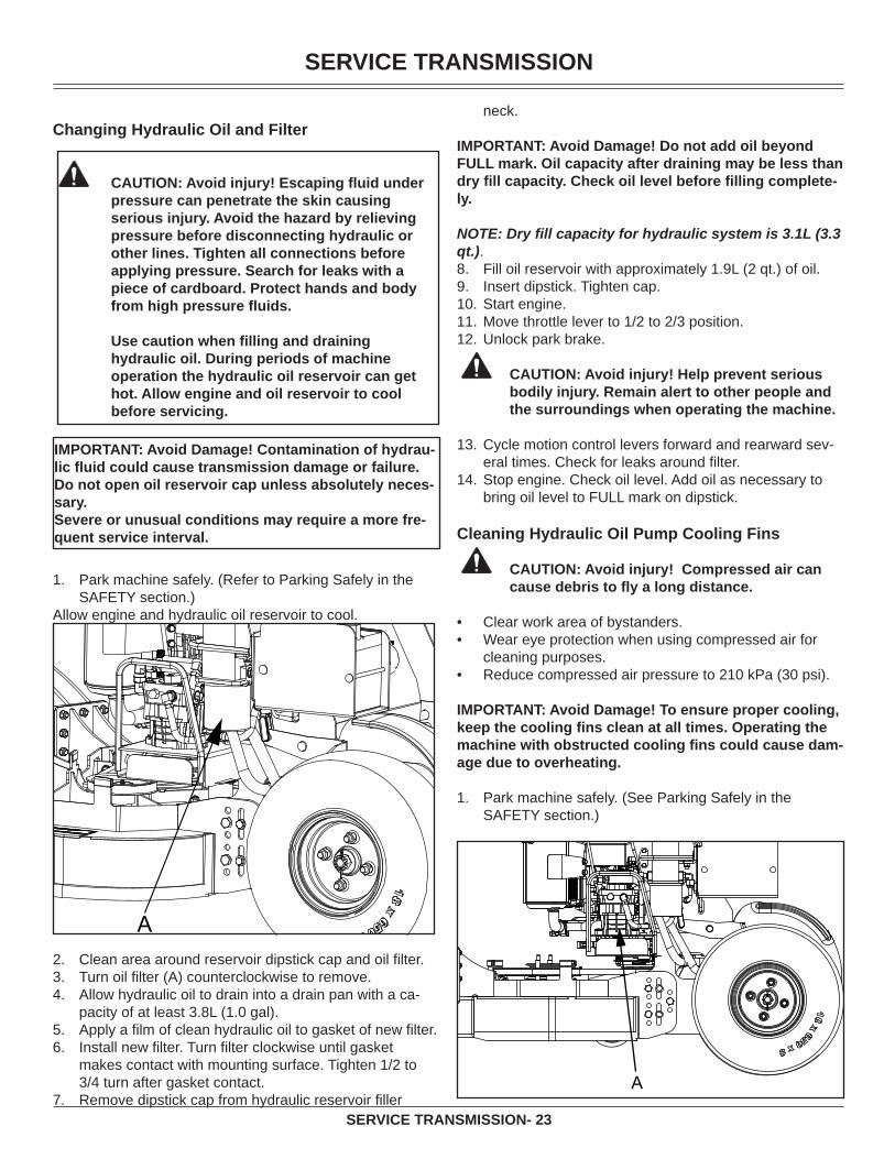
Changing Hydraulic Oil and Filter
CAUTION: Avoid injury! Escaping fl uid under
pressure can penetrate the skin causing serious injury. Avoid the hazard by relieving pressure before disconnecting hydraulic or other lines. Tighten all connections before applying pressure. Search for leaks with a piece of cardboard. Protect hands and body from high pressure fl uids.
Use caution when fi lling and draining hydraulic oil. During periods of machine operation the hydraulic oil reservoir can get hot. Allow engine and oil reservoir to cool before servicing.
IMPORTANT: Avoid Damage! Contamination of hydrau-lic fl uid could cause transmission damage or failure. Do not open oil reservoir cap unless absolutely neces-sary.Severe or unusual conditions may require a more fre-quent service interval.
Park machine safely. (Refer to Parking Safely in the SAFETY section.)
Allow engine and hydraulic oil reservoir to cool.
AClean area around reservoir dipstick cap and oil fi lter.Turn oil fi lter (A) counterclockwise to remove.Allow hydraulic oil to drain into a drain pan with a ca-pacity of at least 3.8L (1.0 gal).Apply a fi lm of clean hydraulic oil to gasket of new fi lter.Install new fi lter. Turn fi lter clockwise until gasket makes contact with mounting surface. Tighten 1/2 to 3/4 turn after gasket contact.Remove dipstick cap from hydraulic reservoir fi ller
1.
2.3.4.
5.6.
7.
neck.
IMPORTANT: Avoid Damage! Do not add oil beyond FULL mark. Oil capacity after draining may be less than dry fi ll capacity. Check oil level before fi lling complete-ly.
NOTE: Dry fi ll capacity for hydraulic system is 3.1L (3.3 qt.).
Fill oil reservoir with approximately 1.9L (2 qt.) of oil. Insert dipstick. Tighten cap.Start engine.Move throttle lever to 1/2 to 2/3 position.Unlock park brake.
CAUTION: Avoid injury! Help prevent serious bodily injury. Remain alert to other people and the surroundings when operating the machine.
Cycle motion control levers forward and rearward sev-eral times. Check for leaks around fi lter.Stop engine. Check oil level. Add oil as necessary to bring oil level to FULL mark on dipstick.
Cleaning Hydraulic Oil Pump Cooling Fins
CAUTION: Avoid injury! Compressed air can cause debris to fl y a long distance.
Clear work area of bystanders.Wear eye protection when using compressed air for cleaning purposes.Reduce compressed air pressure to 210 kPa (30 psi).
IMPORTANT: Avoid Damage! To ensure proper cooling, keep the cooling fi ns clean at all times. Operating the machine with obstructed cooling fi ns could cause dam-age due to overheating.
Park machine safely. (See Parking Safely in the SAFETY section.)
A
8.9.10.11.12.
13.
14.
••
•
1.
SERVICE TRANSMISSION
SERVICE TRANSMISSION- 24
Clean hydraulic oil cooling fi ns on each hydraulic pump with a rag, brush or compressed air.Clean area around hydraulic pumps and frame.
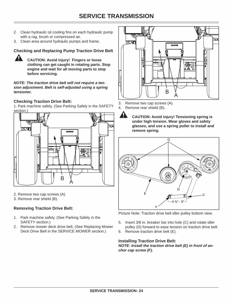
Checking and Replacing Pump Traction Drive Belt
CAUTION: Avoid injury! Fingers or loose clothing can get caught in rotating parts. Stop engine and wait for all moving parts to stop before servicing.
NOTE: The traction drive belt will not require a ten-sion adjustment. Belt is self-adjusted using a spring tensioner.
Checking Traction Drive Belt:1. Park machine safely. (See Parking Safely in the SAFETY section.)
AB
2. Remove two cap screws (A).3. Remove rear shield (B).
Removing Traction Drive Belt:
Park machine safely. (See Parking Safely in the SAFETY section.)Remove mower deck drive belt. (See Replacing Mower Deck Drive Belt in the SERVICE MOWER section.)
2.
3.
1.
2.
AB
Remove two cap screws (A).Remove rear shield (B).
CAUTION: Avoid injury! Tensioning spring is under high tension. Wear gloves and safety glasses, and use a spring puller to install and remove spring.
4 ⅝” - 5”
C
DE
F
G
Picture Note: Traction drive belt idler pulley bottom view.
Insert 3/8 in. breaker bar into hole (C) and rotate idler pulley (D) forward to ease tension on traction drive belt.Remove traction drive belt (E).
Installing Traction Drive Belt:NOTE: Install the traction drive belt (E) in front of an-chor cap screw (F).
3.4.
5.
6.

SERVICE TRANSMISSION
SERVICE TRANSMISSION- 25
4 ⅝” - 5”
C
DE
F
G
Install traction drive belt (E) on drive sheaves (G) as shown. Ensure that traction drive belt is positioned in front of anchor cap screw (F).Insert 3/8 in. breaker bar into hole (C) and rotate idler pulley (D) forward for additional clearance to install traction drive belt.Install rear shield.Install mower deck drive belt.
Checking and Adjusting Motion Control Linkages
CAUTION: Avoid injury! Engine exhaust fumes contain carbon monoxide and can cause seri-ous illness or death.
Move the machine to an outside area before running the engine.Do not run an engine in an enclosed area without adequate ventilation.Connect a pipe extension to the engine ex-haust pipe to direct the exhaust fumes out of the area.Allow fresh outside air into the work area to clear the exhaust fumes out.
•
•
•
•
NOTE: Check and adjust motion control linkages with the machine parked on a hard, level surface.
Checking Motion Control Linkages:1. Park machine safely. (See Parking Safely in the SAFETY section.)
1.
2.
3.4.
1.
A
C
B
Rotate speed control bar (A) to full forward position.With engine off, move motion control levers (B) until they contact the speed control bar (A). A slight defl ec-tion should be seen in the linkage rod (C).
NOTE: Check machine tracking after making adjust-ments.
Start the engine and run until it reaches normal operat-ing temperature.
CAUTION: Avoid injury! Be aware of bystanders.
Stand on the operator’s platform and, with the park brake released, move the motion control levers (B).Observe wheel movement as motion control levers are moved back and forth. Wheels should travel in the cor-rect direction as the levers are moved. Move motion control levers to neutral position. If rear wheels continue to rotate, a return to neutral (RTN) adjustment is required.
Adjusting Motion Control Return to Neutral (RTN) Linkages:
CAUTION: Avoid injury! Fingers or loose clothing can get caught in rotating parts. Stop engine and wait for all moving parts to stop before servicing.
Stop engine.Lock park brake.Lift machine with a safe lifting device centered under rear tire support frame.Start the machine with motion control levers in neutral.Stand on the operator’s platform and release park brake.If rear wheels rotate when motion control levers are in neutral, a neutral adjustment is required.
2.3.
4.
5.
6.
7.
1.2.3.
4.5.
6.
SERVICE TRANSMISSION
SERVICE TRANSMISSION- 26
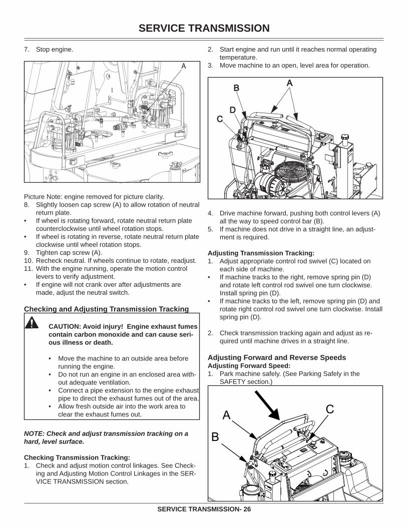
Stop engine.
Picture Note: engine removed for picture clarity.Slightly loosen cap screw (A) to allow rotation of neutral return plate.If wheel is rotating forward, rotate neutral return plate counterclockwise until wheel rotation stops.If wheel is rotating in reverse, rotate neutral return plate clockwise until wheel rotation stops.Tighten cap screw (A).Recheck neutral. If wheels continue to rotate, readjust.With the engine running, operate the motion control levers to verify adjustment.If engine will not crank over after adjustments are made, adjust the neutral switch.
Checking and Adjusting Transmission Tracking
CAUTION: Avoid injury! Engine exhaust fumes contain carbon monoxide and can cause seri-ous illness or death.
Move the machine to an outside area before running the engine.Do not run an engine in an enclosed area with-out adequate ventilation.Connect a pipe extension to the engine exhaust pipe to direct the exhaust fumes out of the area.Allow fresh outside air into the work area to clear the exhaust fumes out.
•
•
•
•
NOTE: Check and adjust transmission tracking on a hard, level surface.
Checking Transmission Tracking:Check and adjust motion control linkages. See Check-ing and Adjusting Motion Control Linkages in the SER-VICE TRANSMISSION section.
7.
8.
•
•
9.10.11.
•
1.
Start engine and run until it reaches normal operating temperature.Move machine to an open, level area for operation.
AB
CD
Drive machine forward, pushing both control levers (A) all the way to speed control bar (B).If machine does not drive in a straight line, an adjust-ment is required.
Adjusting Transmission Tracking:Adjust appropriate control rod swivel (C) located on each side of machine.If machine tracks to the right, remove spring pin (D) and rotate left control rod swivel one turn clockwise. Install spring pin (D).If machine tracks to the left, remove spring pin (D) and rotate right control rod swivel one turn clockwise. Install spring pin (D).
Check transmission tracking again and adjust as re-quired until machine drives in a straight line.
Adjusting Forward and Reverse SpeedsAdjusting Forward Speed:
Park machine safely. (See Parking Safely in the SAFETY section.)
B
A C
2.
3.
4.
5.
1.
•
•
2.
1.
SERVICE STEERING AND BRAKES
SERVICE STEERING AND BRAKES- 27
Picture Note: Arrow shows direction of speed control bar (A) movement when decreasing forward speed.
Loosen lock lever (B) on speed control bar (A).To decrease forward speed, pull speed control bar (A) toward the operator’s station.To increase forward speed, push speed control bar (A) forward (away from operator’s station).
3. Tighten lock lever (B).
Adjusting Reverse Speed:Park machine safely. (See Parking Safely in the SAFETY section.)Loosen jam nut (C) on cap screw (D) on each side of machine.To decrease reverse speed, turn cap screw (D) coun-terclockwise.To increase reverse speed, turn cap screw (D) clock-wise.Tighten jam nut (C) on cap screw (D) on each side of machine.
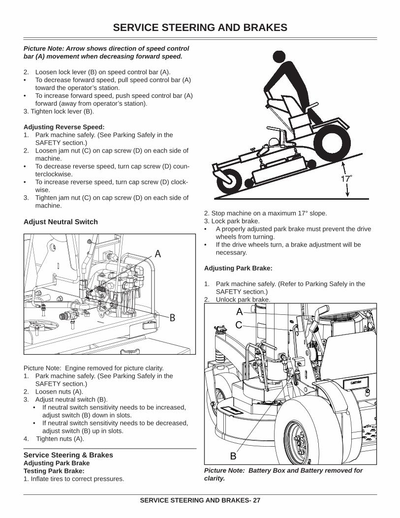
Adjust Neutral Switch
Picture Note: Engine removed for picture clarity.Park machine safely. (See Parking Safely in the SAFETY section.)Loosen nuts (A).Adjust neutral switch (B).
If neutral switch sensitivity needs to be increased, adjust switch (B) down in slots.If neutral switch sensitivity needs to be decreased, adjust switch (B) up in slots.
4. Tighten nuts (A).
Service Steering & BrakesAdjusting Park Brake Testing Park Brake:1. Infl ate tires to correct pressures.
2.•
•
1.
2.
•
•
3.
1.
2.3.
•
•
2. Stop machine on a maximum 17° slope.3. Lock park brake.
A properly adjusted park brake must prevent the drive wheels from turning.If the drive wheels turn, a brake adjustment will be necessary.
Adjusting Park Brake:
Park machine safely. (Refer to Parking Safely in the SAFETY section.) Unlock park brake.
AC
BPicture Note: Battery Box and Battery removed for clarity.
•
•
1.
2.
SERVICE MOWER
SERVICE MOWER - 28
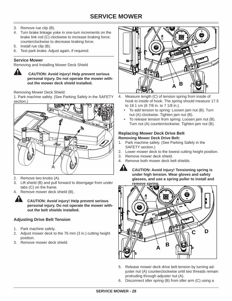
Remove rue clip (B). Turn brake linkage yoke in one-turn increments on the brake link rod (C) clockwise to increase braking force; counterclockwise to decrease braking force.Install rue clip (B).Test park brake. Adjust again, if required.
Service MowerRemoving and Installing Mower Deck Shield
CAUTION: Avoid injury! Help prevent serious personal injury. Do not operate the mower with-out the mower deck shield installed.
Removing Mower Deck Shield:1. Park machine safely. (See Parking Safely in the SAFETY section.)
A
Remove two knobs (A).Lift shield (B) and pull forward to disengage from under tabs (C) on the frame.Remove mower deck shield (B).
CAUTION: Avoid injury! Help prevent serious personal injury. Do not operate the mower with-out the belt shields installed.
Adjusting Drive Belt Tension
Park machine safely.Adjust mower deck to the 76 mm (3 in.) cutting height position.Remove mower deck shield.
3.4.
5.6.
2.3.
4.
1.2.
3.
C
A B
Measure length (C) of tension spring from inside of hook to inside of hook. The spring should measure 17.5 to 18.1 cm (6 7/8 in. to 7 1/8 in.).
To add tension to spring: Loosen jam nut (B). Turn nut (A) clockwise. Tighten jam nut (B).To release tension from spring: Loosen jam nut (B). Turn nut (A) counterclockwise. Tighten jam nut (B).
Replacing Mower Deck Drive Belt Removing Mower Deck Drive Belt:
Park machine safely. (See Parking Safely in the SAFETY section.)Lower mower deck to the lowest cutting height position.Remove mower deck shield.Remove both mower deck belt shields.
CAUTION: Avoid injury! Tensioning spring is under high tension. Wear gloves and safety glasses, and use a spring puller to install and remove spring.
A B
C D
Release mower deck drive belt tension by turning ad-juster nut (A) counterclockwise until two threads remain protruding through adjuster nut (A).Disconnect idler spring (B) from idler arm (C) using a
4.
•
•
1.
2.3.4.
5.
6.

SERVICE MOWER
SERVICE MOWER - 29
spring puller tool.Remove mower deck drive belt (D).
Installing Mower Deck Drive Belt:
NOTE: If necessary, see drive belt installation label on mower deck.
BELT ROUTING
201043
A
Install replacement drive belt (A) as shown on mower deck drive belt label. Make sure drive belt is installed properly on PTO clutch sheave, spindle sheaves and idler pulleys.
C
A B
Connect idler tension spring and adjust tension. The length (C) of the tension spring should measure 17.5 to 18.1 cm (6 7/8 in. to 7 1/8 in.) from inside of hook to inside of hook.Install both mower deck belt shields.Install mower deck shield.Adjust mower deck to desired cutting height.
Checking for Bent Mower Blades
CAUTION: Avoid injury! Mower blades are sharp. Always wear gloves when handling mower blades or working near blades.
7.
1.
2.
3.4.5.
Replace blades if defective. Never straighten or weld them.
Park machine safely. (See Parking Safely in the SAFETY section.)Raise mower to highest position to access blades.
Picture Note: Mower deck with side discharge used for illustration.
Measure distance (A) between blade tip and fl at ground surface.Rotate blade 180° and measure distance between other blade tip and fl at ground surface.Install new blade if the difference between the two measurements is more than 3 mm (1/8 in.).Repeat for all blades.
Checking and Replacing Mower Blades
CAUTION: Avoid injury! Do not work near raised mower deck unless it is safely supported.
Mower blades are sharp. Wrap blades or wear gloves when servicing.Before performing any service function, wait for all moving parts to stop turning.Disconnect battery or remove spark plug wire before making repairs.
•
•
•
IMPORTANT: Avoid Damage! When replacing mower blades, always use genuine EverRide Service Parts.
NOTE: Only replace blades. Never straighten or weld them.
Checking Mower BladesPark machine safely. (See Parking Safely in the Safety Section).Raise the mower deck to the transport position (also the 12.7 cm [5 in.] cutting height position).Raise front of machine with a safe lifting device.
Support with jack stands and/or wooden blocks.
1.
2.
3.
4.
5.
6.
1.
2.
3.•
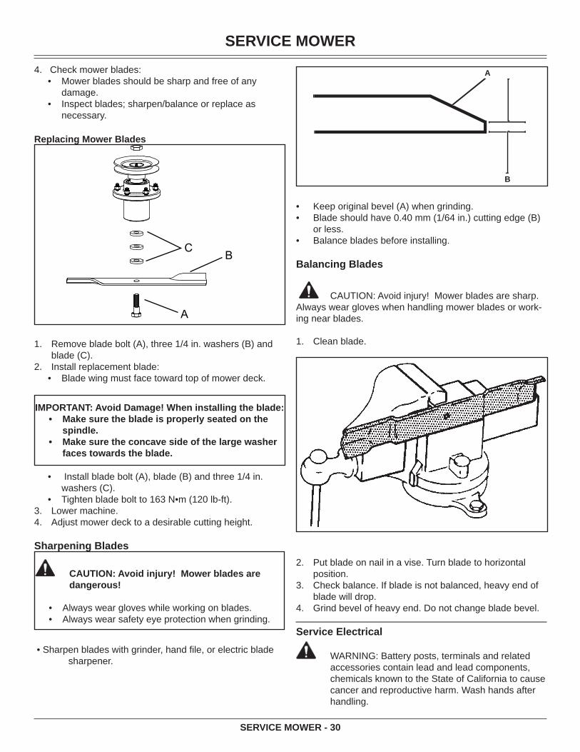
SERVICE MOWER
SERVICE MOWER - 30
4. Check mower blades:• Mower blades should be sharp and free of any
damage.• Inspect blades; sharpen/balance or replace as
necessary.
Replacing Mower Blades
A
BC
Remove blade bolt (A), three 1/4 in. washers (B) and blade (C). Install replacement blade:
Blade wing must face toward top of mower deck.
IMPORTANT: Avoid Damage! When installing the blade:Make sure the blade is properly seated on the spindle.Make sure the concave side of the large washer faces towards the blade.
•
•
Install blade bolt (A), blade (B) and three 1/4 in. washers (C).Tighten blade bolt to 163 N•m (120 lb-ft).
Lower machine.Adjust mower deck to a desirable cutting height.
Sharpening Blades
CAUTION: Avoid injury! Mower blades are dangerous!
Always wear gloves while working on blades.Always wear safety eye protection when grinding.
••
• Sharpen blades with grinder, hand fi le, or electric blade sharpener.
1.
2.•
•
•3.4.
A
B
Keep original bevel (A) when grinding.Blade should have 0.40 mm (1/64 in.) cutting edge (B) or less.Balance blades before installing.
Balancing Blades
CAUTION: Avoid injury! Mower blades are sharp. Always wear gloves when handling mower blades or work-ing near blades.
Clean blade.
Put blade on nail in a vise. Turn blade to horizontal position.Check balance. If blade is not balanced, heavy end of blade will drop.Grind bevel of heavy end. Do not change blade bevel.
Service Electrical
WARNING: Battery posts, terminals and related accessories contain lead and lead components, chemicals known to the State of California to cause cancer and reproductive harm. Wash hands after handling.
••
•
1.
2.
3.
4.
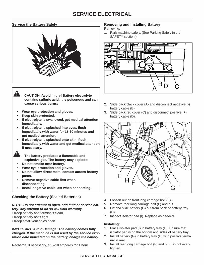
SERVICE ELECTRICAL
SERVICE ELECTRICAL - 31
Service the Battery Safely
CAUTION: Avoid injury! Battery electrolyte contains sulfuric acid. It is poisonous and can cause serious burns:
Wear eye protection and gloves.Keep skin protected.If electrolyte is swallowed, get medical attention immediately.If electrolyte is splashed into eyes, fl ush immediately with water for 15-30 minutes and get medical attention.If electrolyte is splashed onto skin, fl ush immediately with water and get medical attention if necessary.
The battery produces a fl ammable and explosive gas. The battery may explode:
Do not smoke near battery.Wear eye protection and gloves.Do not allow direct metal contact across battery posts.Remove negative cable fi rst when disconnecting.Install negative cable last when connecting.
•••
•
•
•••
•
•
Checking the Battery (Sealed Batteries)
NOTE: Do not attempt to open, add fl uid or service bat-tery. Any attempt to do so will void warranty.• Keep battery and terminals clean.• Keep battery bolts tight.• Keep small vent holes open.
IMPORTANT: Avoid Damage! The battery comes fully charged. If the machine is not used by the service expi-ration date indicated on the battery, charge the battery.
Recharge, if necessary, at 6–10 amperes for 1 hour.
Removing and Installing BatteryRemoving:
Park machine safely. (See Parking Safely in the SAFETY section.)
C
AB CD
Slide back black cover (A) and disconnect negative (-) battery cable (B).Slide back red cover (C) and disconnect positive (+) battery cable (D).
EH F
G I
Loosen nut on front long carriage bolt (E).Remove rear long carriage bolt (F) and nut.Lift and slide battery (G) out from back of battery tray (H).Inspect isolator pad (I). Replace as needed.
Installing:Place isolator pad (I) in battery tray (H). Ensure that isolator pad is on the bottom and sides of battery tray. Install battery (G) in battery tray (H) with positive termi-nal in rear.Install rear long carriage bolt (F) and nut. Do not over-tighten.
1.
2.
3.
4.5.6.
7.
1.
2.
3.

SERVICE ELECTRICAL
SERVICE ELECTRICAL - 32
Tighten nut on long carriage bolt (E) to secure battery (G) in battery tray (H). Do not overtighten.Apply dielectric grease to terminals to prevent corro-sion.Connect the positive (+) battery cable (D) and install cover (C).Connect negative (-) battery cable (B) and install cover (A).
Cleaning Battery and Terminals
Park machine safely. (See Parking Safely in the SAFETY section.)Disconnect and remove battery.Wash battery with solution of four tablespoons of bak-ing soda to one gallon of water. Be careful not to get the soda solution into the cells.Rinse the battery with plain water and dry.Clean terminals and battery cable ends with wire brush until bright.Apply general purpose grease or silicone spray to ter-minal to prevent corrosion.Install battery.
Using Booster Battery
CAUTION: Avoid injury! The battery produces a fl ammable and explosive gas. The battery may explode:
Do not smoke or have open fl ame near battery.Wear eye protection and gloves.Do not jump start or charge a frozen battery. Warm battery to 16°C (60°F).Do not connect the negative (-) booster cable to the negative (-) terminal of the discharged battery. Connect at a good ground location away from the discharged battery.
•••
•
A BB
4.
5.
6.
7.
1.
2.3.
4.5.
6.
7.
A - Booster BatteryB - Disabled Vehicle Battery
Connect positive (+) booster cable to booster battery (A) positive (+) post (C). Connect the other end of positive (+) booster cable to the disabled vehicle battery (B) positive (+) post (D).Connect negative (–) booster cable to booster battery negative (–) post (E).
IMPORTANT: Avoid Damage! Electric charge from booster battery can damage machine components. Do not install negative booster cable to machine frame. Install only to the engine block.
Install negative booster cable away from moving parts in the engine compartment, such as belts and fan blades.
Connect the other end (F) of negative (–) booster cable to a metal part of the disabled machine engine block away from battery.Start the engine of the disabled machine and run ma-chine for several minutes.Carefully disconnect the booster cables in the exact reverse order: negative cable fi rst and then the positive cable.
Replacing FuseThe electric start circuit is protected by one 20 Amp fuse.
IMPORTANT: Avoid Damage! Help prevent machine circuit damage. Make sure replacement fuse is the correct size.
Locate electric start fuse holder under console on the machine.
Open fuse holder (A) and remove socket with fuse.Check metal clip in fuse window. Discard fuse if clip is broken.Install new 20 Amp fuse in socket.Install socket with fuse in cover. Ensure that plastic tab of fuse holder is securely fastened to fuse socket.
1.
2.
3.
4.
5.
6.
1.
••
••
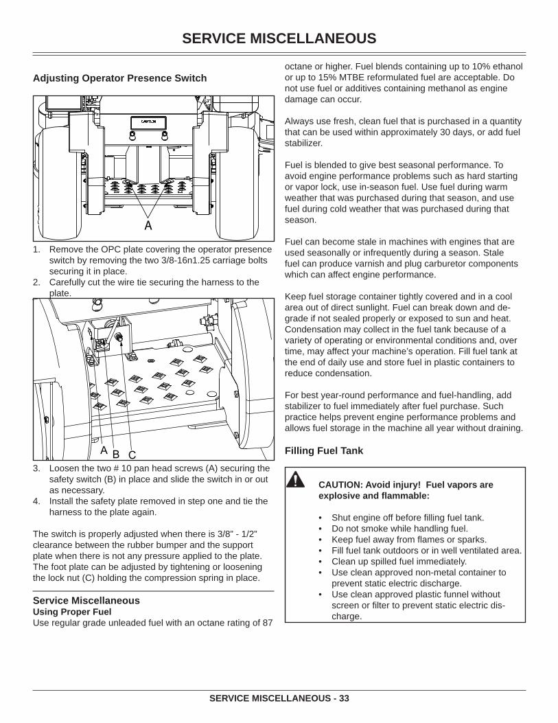
SERVICE MISCELLANEOUS
SERVICE MISCELLANEOUS - 33
Adjusting Operator Presence Switch
Remove the OPC plate covering the operator presence switch by removing the two 3/8-16n1.25 carriage bolts securing it in place.Carefully cut the wire tie securing the harness to the plate.
A B CLoosen the two # 10 pan head screws (A) securing the safety switch (B) in place and slide the switch in or out as necessary.Install the safety plate removed in step one and tie the harness to the plate again.
The switch is properly adjusted when there is 3/8” - 1/2” clearance between the rubber bumper and the support plate when there is not any pressure applied to the plate. The foot plate can be adjusted by tightening or loosening the lock nut (C) holding the compression spring in place.
Service MiscellaneousUsing Proper FuelUse regular grade unleaded fuel with an octane rating of 87
1.
2.
3.
4.
octane or higher. Fuel blends containing up to 10% ethanol or up to 15% MTBE reformulated fuel are acceptable. Do not use fuel or additives containing methanol as engine damage can occur.
Always use fresh, clean fuel that is purchased in a quantity that can be used within approximately 30 days, or add fuel stabilizer.
Fuel is blended to give best seasonal performance. To avoid engine performance problems such as hard starting or vapor lock, use in-season fuel. Use fuel during warm weather that was purchased during that season, and use fuel during cold weather that was purchased during that season.
Fuel can become stale in machines with engines that are used seasonally or infrequently during a season. Stale fuel can produce varnish and plug carburetor components which can affect engine performance.
Keep fuel storage container tightly covered and in a cool area out of direct sunlight. Fuel can break down and de-grade if not sealed properly or exposed to sun and heat.Condensation may collect in the fuel tank because of a variety of operating or environmental conditions and, over time, may affect your machine’s operation. Fill fuel tank at the end of daily use and store fuel in plastic containers to reduce condensation.
For best year-round performance and fuel-handling, add stabilizer to fuel immediately after fuel purchase. Such practice helps prevent engine performance problems and allows fuel storage in the machine all year without draining.
Filling Fuel Tank
CAUTION: Avoid injury! Fuel vapors are explosive and fl ammable:
Shut engine off before fi lling fuel tank.Do not smoke while handling fuel.Keep fuel away from fl ames or sparks.Fill fuel tank outdoors or in well ventilated area.Clean up spilled fuel immediately.Use clean approved non-metal container to prevent static electric discharge.Use clean approved plastic funnel without screen or fi lter to prevent static electric dis-charge.
••••••
•
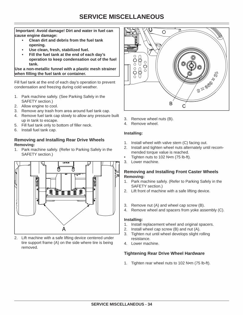
SERVICE MISCELLANEOUS
SERVICE MISCELLANEOUS - 34
Important: Avoid damage! Dirt and water in fuel can cause engine damage:
Clean dirt and debris from the fuel tank opening.Use clean, fresh, stabilized fuel.Fill the fuel tank at the end of each day’s operation to keep condensation out of the fuel tank.
Use a non-metallic funnel with a plastic mesh strainer when fi lling the fuel tank or container.
•
••
Fill fuel tank at the end of each day’s operation to prevent condensation and freezing during cold weather.
Park machine safely. (See Parking Safely in the SAFETY section.)Allow engine to cool.Remove any trash from area around fuel tank cap.Remove fuel tank cap slowly to allow any pressure built up in tank to escape.Fill fuel tank only to bottom of fi ller neck.Install fuel tank cap.
Removing and Installing Rear Drive WheelsRemoving:
Park machine safely. (Refer to Parking Safely in the SAFETY section.)
Lift machine with a safe lifting device centered under tire support frame (A) on the side where tire is being removed.
1.
2.3.4.
5.6.
1.
2.
B C
Remove wheel nuts (B).Remove wheel.
Installing:
Install wheel with valve stem (C) facing out.Install and tighten wheel nuts alternately until recom-mended torque value is reached.Tighten nuts to 102 N•m (75 lb-ft).Lower machine.
Removing and Installing Front Caster WheelsRemoving:
Park machine safely. (Refer to Parking Safely in the SAFETY section.) Lift front of machine with a safe lifting device.
Remove nut (A) and wheel cap screw (B).Remove wheel and spacers from yoke assembly (C).
Installing:Install replacement wheel and original spacers.Install wheel cap screw (B) and nut (A).Tighten nut until wheel develops slight rolling resistance.Lower machine.
Tightening Rear Drive Wheel Hardware
Tighten rear wheel nuts to 102 N•m (75 lb-ft).
3.4.
1.2.
•3.
1.
2.
3.4.
1.2.3.
4.
1.
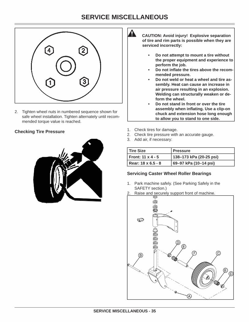
SERVICE MISCELLANEOUS
SERVICE MISCELLANEOUS - 35
Tighten wheel nuts in numbered sequence shown for safe wheel installation. Tighten alternately until recom-mended torque value is reached.
Checking Tire Pressure
2.
CAUTION: Avoid injury! Explosive separation of tire and rim parts is possible when they are serviced incorrectly:
Do not attempt to mount a tire without the proper equipment and experience to perform the job.Do not infl ate the tires above the recom-mended pressure.Do not weld or heat a wheel and tire as-sembly. Heat can cause an increase in air pressure resulting in an explosion. Welding can structurally weaken or de-form the wheel.Do not stand in front or over the tire assembly when infl ating. Use a clip-on chuck and extension hose long enough to allow you to stand to one side.
•
•
•
•
Check tires for damage.Check tire pressure with an accurate gauge.Add air, if necessary:
Tire Size Pressure Front: 11 x 4 - 5 138–173 kPa (20-25 psi)Rear: 18 x 6.5 - 8 69–97 kPa (10–14 psi)
Servicing Caster Wheel Roller Bearings
Park machine safely. (See Parking Safely in the SAFETY section.)Raise and securely support front of machine.
1.2.3.
1.
2.

SERVICE MISCELLANEOUS
SERVICE MISCELLANEOUS - 36
Remove locknut (A), cap screw (B), and wheel assem-bly (C).Remove seals (D) and bearings (E) from wheel.Clean and inspect bearings (E). Replace as needed.Repack bearings with clean grease. Install bearings (E) and wheel spacer (F) (if removed), and new seals (D).Install wheel assembly (C), cap screw (B) and locknut (A).Use a grease gun to fi ll hub until grease just appears at one of the seals (D).Lower machine.
Cleaning and Repairing Plastic Surfaces
Your authorized dealer has the professional materials need-ed to properly remove surface scratches from any plastic surfaces, do not attempt to paint over marks or scratches in plastic parts.
IMPORTANT: Avoid Damage! Improper care of machine plastic surfaces can damage that surface:
Do not wipe plastic surfaces when they are dry. Dry wiping will result in minor surface scratches.Use a soft, clean cloth (bath towel, diaper, automotive mitt).Do not use abrasive materials, such as pol-ishing compounds, on plastic surfaces.Do not spray insect repellent near machine.
•
•
•
•
Wash surface with clean water and a mild liquid auto-motive washing soap.Dry thoroughly to avoid water spots.
Cleaning and Repairing Metal SurfacesCleaning:Follow automotive practices to care for your vehicle painted metal surfaces. Use a high-quality automotive wax regu-larly to maintain the factory look of your vehicle’s painted surfaces.Repairing Minor Scratches (surface scratch):
Clean area to be repaired thoroughly.
IMPORTANT: Avoid damage! Do not use rubbing com-pound on painted surfaces.
Use automotive polishing compound to remove surface scratches.Apply wax to entire surface.
Repairing Deep Scratches (bare metal or primer show-ing):
3.
4.5.6.7.
8.
9.
10.
1.
2.
1.
1.
2.
Clean area to be repaired with rubbing alcohol or min-eral spirits.Use paint stick with factory-matched colors available from your authorized dealer to fi ll scratches. Follow directions included on paint stick for use and for drying.Smooth out surface using an automotive polishing compound. Do not use power buffer.Apply wax to surface.
TroubleshootingUsing Troubleshooting ChartIf you are experiencing a problem that is not listed in this chart, see your authorized dealer for service.When you have checked all the possible causes listed and you are still experiencing the problem, see your authorized dealer.If CheckPoor Engine Performance
Fuel:
• Dirt in fuel system or fuel is old. Replace fuel with fresh stabilized fuel. Obtain fuel from another supplier before suspecting machine problems. Suppliers blend fuels differently and changing suppliers will generally solve any performance problems.
• Fuel blended with alcohol or ether may contribute to performance problems by causing gum and varnish deposits, especially if fuel is stored for several weeks or more. Obtain fresh fuel.
Engine Will Not Start Or Is Hard To Start
• Park brake lever not in the proper position.
• OPC switch not depressed. Stand on platform or adjust switch.
• Check that motion control levers are in neutral and neutral switches are correctly adjusted.
• PTO engaged.
• Stale or improper fuel/fuel level.
• Plugged fuel fi lter.
• Plugged air intake fi lter.
• Spark plug wires loose or disconnected.
• Spark plugs not gapped correctly.
• Blown fuse.
• Electrical problem – dead battery.
1.
2.
3.
4.

TROUBLESHOOTING
TROUBLESHOOTING - 37
• Choke adjusted incorrectly. See your authorized dealer.
Engine Will Not Slow Idle
• Carburetion problems. See your authorized dealer.
• Bent or kinked throttle cable.
• Bent governor control.
• Incorrect governor idle control.
Engine Runs Rough or Stalls
• Plugged fuel fi lter.
• Plugged air intake system.
• Fuel cap vent dirty.
• Stale or improper fuel/fuel level.
• Spark plugs not gapped correctly.
• Replace spark plugs.
• Choke adjusted incorrectly. See your authorized dealer.
Engine Knocks • Engine oil level low.• Reduce load. (Slower ground
speed.)• Fuel is bad. Fill tank with fresh
fuel, correct octane.• Idle speed too slow.
Engine Overheats • Clean cooling fi ns.• Low oil level.
• Do not operate at slow idle. Operate at fast idle.
• Cooling air intake screen is dirty.
• Plugged carburetor air intake fi lter.
• Plugged air intake fi lter.
• Operating at too fast ground speed for conditions.
Engine Lacks Power • Reduce load.• Plugged air intake system.
• Plugged fuel fi lter.
• Improper type of fuel. Drain tank and fi ll with correct fuel.
• Clean cooling fi ns to help prevent overheating.
• Replace spark plugs.
Engine Uses Too Much Oil
• Find and correct oil leaks.
• Incorrect engine oil.
• Plugged oil fi lter.
• Plugged air intake fi lter.
• Worn engine components.
Engine Backfi res Through Muffl er
• Throttle lever should be at low idle for thirty seconds before turning off machine.
High Fuel Consumption
• Improper type of fuel.
• Plugged air intake system.
• Operating at too fast ground speed for conditions.
• Improper valve clearance. See your authorized dealer.
• Restricted air intake system.
Other Symptoms • See engine manufacturer’s owner’s manual provided with your machine for additional information.
Electrical System
If CheckStarter Will Not Work • Blown fuse.
• OPC Switch faulty or not adjusted properly.
• Park brake switch is faulty.
• Loose or corroded battery connections.
• Neutral switches faulty or not adjusted properly. See your authorized dealer.
• Key switch or starter faulty. See your • authorized dealer.
• PTO engaged.
• Motion control levers and park brake lever not in proper position.
Battery Will Not Charge
• Loose or corroded connections.
• Blown fuse or fusible link. See your authorized dealer.
PTO Switch Does Not Work
• Blown fuse.
• PTO switch faulty.
Starter Turns Slowly • Loose or corroded battery connections.
• Low battery power-charge battery.
• Engine oil viscosity too heavy.
STORAGE
STORAGE - 38
• Hydraulic pump linkage out of adjustment-pumps engaged.
Machine
If CheckExcessive Machine Vibration
• Engine speed too slow.
• Deck drive belt not tensioned correctly.
• Mower blades not balanced.
Machine Will Not Move With Engine Running
• Park brake locked.
• Transmission oil level low.
• Transmission oil cold – allow engine to warm up.
• Pump drive belt slipping or broken.
• Pump drive belt spring broken.
• Pump free-wheel valves open.
• Transmission problems. See your authorized dealer.
Machine Creeps With Engine Running and Motion Control Levers in a Neutral Position
• Needs motion control linkage adjustment.
• Needs Adjustment.
Park Brake
If CheckPark Brake Not Working Correctly
• Park brake out of adjustment – adjust linkage.
Steering
If CheckSteering Not Working
• Pump free-wheel valves partially open.
• Improper tire infl ation.
• Hydrostatic transmission oil level low.
• Traction drive loose or broken.
• Hydraulic pump or wheel motor faulty.
Mower Deck
If CheckDischarge Chute Plugged
• Grass is wet-mow grass only when dry.
• Raise cutting height.
• Mow with engine at full fast throttle.
• Ground speed too fast for conditions.
• Correct installation of deck drive belt.
Mower Deck Vibrates
• Run engine at fast throttle.
• Loose hardware.
• Check/replace deck drive belt.
• Blade bolts are loose.
• Blades are bent or worn.
• Sharpen and balance blades.
• Remove belt shields and clean debris from sheaves.
• Check sheaves for proper alignment or damage. See authorized dealer.
Mower Blades Do Not Engage
• Deck drive belt slipping or broken.
• Deck belt tension spring not installed or broken.
• PTO switch faulty.
• Fuse blown.
• Loose electrical connections.
• PTO clutch faulty.
Mower Mows Unevenly
• Mower deck not properly leveled.
• Ground speed too fast for conditions.
• Run engine at fast throttle.
• Reduce ground speed when making turns.
• Sharpen or replace blades.

STORAGE
STORAGE - 39
• Change mowing pattern.
• Check air pressure in all traction unit tires.
• Anti-scalp rollers not adjusted correctly.
StorageStoring Safety
CAUTION: Avoid injury! Fuel vapors are ex-plosive and fl ammable. Engine exhaust fumes contain carbon monoxide and can cause seri-ous illness or death:
Run the engine only long enough to move the machine to or from storage.Do not store vehicle with fuel in the tank inside a building where fumes may reach an open fl ame or spark.Allow the engine to cool before storing the machine in any enclosure.
Preparing Machine for StorageRepair any worn or damaged parts. Replace parts if necessary. Tighten loose hardware.Repair scratched or chipped metal surfaces to prevent rust.Remove grass and debris from machine.Clean under the deck and remove grass and debris from inside chute and bagger.Wash the machine and apply wax to metal and plastic surfaces. Run machine for fi ve minutes to dry belts and pulleys.Apply light coat of engine oil to pivot and wear points to prevent rust.Lubricate grease points and check tire pressure.
Preparing Fuel and Engine For StorageFuel:If you have been using “Stabilized Fuel,” add stabilized fuel to tank until the tank is full.NOTE: Filling the fuel tank reduces the amount of air in the fuel tank and helps reduce deterioration of fuel.If you are not using “Stabilized Fuel:”
Park machine safely in a well-ventilated area. (See Parking Safely in the SAFETY section.)
NOTE: Try to anticipate the last time the machine will be used for the season so very little fuel is left in the fuel tank.
Turn on engine and allow to run until it runs out of fuel.For machines equipped with key switch, turn key to off position.
IMPORTANT: Avoid Damage! Stale fuel can produce varnish and plug carburetor or injector components and affect engine performance.
1.
2.
3.4.
5.
6.7.
8.
1.
2.3.
Add fuel conditioner or stabilizer to fresh fuel before fi lling tank.
Mix fresh fuel and fuel stabilizer in separate container. Follow stabilizer instructions for mixing.Fill fuel tank with stabilized fuel.Run engine for a few minutes to allow fuel mixture to circulate through carburetor on gas engine or fuel injec-tors on diesel engine.
Engine:Engine storage procedure should be used when vehicle is not to be used for longer than 60 days.
Change engine oil and fi lter while engine is warm.Service air fi lter if necessary.Clean debris from engine air intake screen.On gas engines:Remove spark plugs. Put 30 mL (1 oz) of clean engine oil in cylinders.Install spark plugs, but do not connect spark plug wires.Crank the engine fi ve or six times to allow oil to be distributed.Clean the engine and engine compartment.Remove battery.Clean the battery and battery posts. Check the electro-lyte level, if your battery is not maintenance free. Close fuel shut-off valve, if your machine is equipped.Store the battery in a cool, dry place where it will not freeze.
NOTE: The stored battery should be recharged every 90 days.
Charge the battery.
IMPORTANT: Avoid Damage! Prolonged exposure to sunlight could damage the hood surface. Store ma-chine inside or use a cover if stored outside.
Store the vehicle in a dry, protected place. If vehicle is stored outside, put a waterproof cover over it.
Removing Machine From StorageCheck tire pressure. Check engine oil level.Check battery electrolyte level, if your battery is not maintenance free. Charge battery if necessary. Install battery. On gas engines: Check spark plug gap. Install and tighten plugs to specifi ed torque.Lubricate all grease points.Open fuel shut-off valve, if your machine is equipped.Run the engine 5 minutes without the mower or any at-tachments running to allow oil to be distributed through-out engine.Be sure all shields and guards or defl ectors are in place.
•
4.
5.6.
1.2.3.4.•
••
5.6.7.
8.9.
10.
11.
1.2.3.
4.5.
6.7.8.
9.

ASSEMBLY
ASSEMBLY - 40
AssemblyConnect Handles
The handles are disconnected and rotated forward dur-ing assembly to allow for proper fi tment into the shipping container.
Rotate the handles up.
AB
C
Connect the pump control arm (C) to the handle weldment by inserting the adjustment block (A) into the handle weldment and securing with the hairpin clip (B).Set the speed control bar to desired speed and lock.
Check Hydraulic Oil Level
AB
Clean area around dipstick cap (A).Remove dipstick cap (A). Wipe dipstick clean.
NOTE: Do not tighten dipstick cap when checking oil level.
Insert dipstick in fi ller neck (B). Do not tighten cap.Remove dipstick. Check oil level on dipstick. Oil level should be between the ADD and FULL marks on dip-stick.
If oil is level is below ADD mark, fi ll to proper level.If oil level is above FULL mark, drain to proper level.
Insert dipstick. Tighten cap.
1.
2.
3.
1.2.
3.4.
•
•
5.
Check Engine Oil Level
Clean area around dipstick cap (A).Remove dipstick cap (A) from tube. Wipe dipstick clean.
NOTE: Do not tighten dipstick cap when checking oil level.
Insert dipstick in tube. Do not tighten cap.Remove dipstick. Check oil level on dipstick. Oil level should be between the ADD and FULL marks.
If oil is level is below ADD mark, fi ll to proper level.If oil level is above the FULL mark, drain to proper level.
Insert dipstick. Tighten cap.
Connect Battery
CAUTION: Avoid injury! Prevent Battery Explo-sions:
• Keep sparks, lighted matches, and open fl ame away from the top of battery. Battery gas can explode.• Never check battery charge by placing a metal object across the posts. Use a volt-meter or hydrometer.• Do not charge a frozen battery; it may explode. Warm battery to 16 degrees C (60 degrees F).
Connect positive (red) cable to battery positive (+) terminal. Install red terminal cover (A).Connect negative (black) cable to battery negative (-) terminal. Install black terminal cover (B).
Check Machine Safety SystemsPerform safety system check to make sure the electronic safety interlock circuit is functioning properly.
1.2.
3.4.
•
•
5.
1.
2.
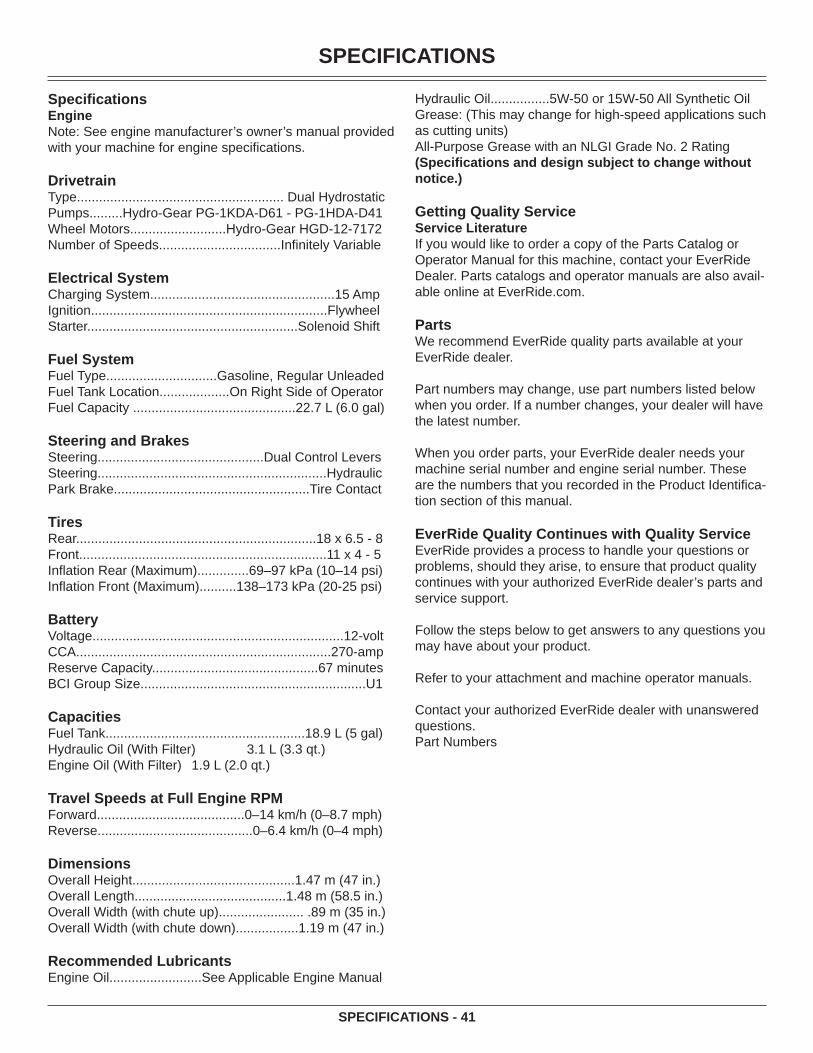
SPECIFICATIONS
SPECIFICATIONS - 41
Specifi cationsEngineNote: See engine manufacturer’s owner’s manual provided with your machine for engine specifi cations.
DrivetrainType........................................................ Dual HydrostaticPumps.........Hydro-Gear PG-1KDA-D61 - PG-1HDA-D41Wheel Motors..........................Hydro-Gear HGD-12-7172Number of Speeds.................................Infi nitely Variable
Electrical SystemCharging System..................................................15 AmpIgnition................................................................FlywheelStarter.........................................................Solenoid Shift
Fuel SystemFuel Type..............................Gasoline, Regular UnleadedFuel Tank Location...................On Right Side of OperatorFuel Capacity ............................................22.7 L (6.0 gal)
Steering and BrakesSteering.............................................Dual Control LeversSteering..............................................................HydraulicPark Brake.....................................................Tire Contact
TiresRear.................................................................18 x 6.5 - 8Front...................................................................11 x 4 - 5Infl ation Rear (Maximum)..............69–97 kPa (10–14 psi)Infl ation Front (Maximum)..........138–173 kPa (20-25 psi)
BatteryVoltage....................................................................12-voltCCA.....................................................................270-ampReserve Capacity.............................................67 minutesBCI Group Size.............................................................U1
CapacitiesFuel Tank......................................................18.9 L (5 gal)Hydraulic Oil (With Filter) 3.1 L (3.3 qt.)Engine Oil (With Filter) 1.9 L (2.0 qt.)
Travel Speeds at Full Engine RPMForward........................................0–14 km/h (0–8.7 mph)Reverse..........................................0–6.4 km/h (0–4 mph)
DimensionsOverall Height............................................1.47 m (47 in.)Overall Length.........................................1.48 m (58.5 in.)Overall Width (with chute up)....................... .89 m (35 in.)Overall Width (with chute down).................1.19 m (47 in.)
Recommended LubricantsEngine Oil.........................See Applicable Engine Manual
Hydraulic Oil................5W-50 or 15W-50 All Synthetic OilGrease: (This may change for high-speed applications such as cutting units)All-Purpose Grease with an NLGI Grade No. 2 Rating(Specifi cations and design subject to change without notice.)
Getting Quality ServiceService LiteratureIf you would like to order a copy of the Parts Catalog or Operator Manual for this machine, contact your EverRide Dealer. Parts catalogs and operator manuals are also avail-able online at EverRide.com.
PartsWe recommend EverRide quality parts available at your EverRide dealer.
Part numbers may change, use part numbers listed below when you order. If a number changes, your dealer will have the latest number.
When you order parts, your EverRide dealer needs your machine serial number and engine serial number. These are the numbers that you recorded in the Product Identifi ca-tion section of this manual.
EverRide Quality Continues with Quality ServiceEverRide provides a process to handle your questions or problems, should they arise, to ensure that product quality continues with your authorized EverRide dealer’s parts and service support.
Follow the steps below to get answers to any questions you may have about your product.
Refer to your attachment and machine operator manuals.
Contact your authorized EverRide dealer with unanswered questions.Part Numbers

GETTING QUALITY SERVICE
GETTING QUALITY SERVICE - 42
Item Part NumberMower Blades:34-Inch Deck - LH Blade GDU1023134-Inch Deck - RH Blade GDU10230Hydraulic Oil Filter GDU10137Battery 191832Fuse - 20 amp 57M7120
Belts:Hydraulic Drive Belt 20100934-Inch Mower Deck Belt 201010
(Part numbers are subject to change without notice. Part Numbers may be different outside the U.S.A.)

WIRING DIAGRAM
Wiring Diagram - 43
GY
GY
RR
TNTN
GN
GNY
W
Y
WLT
/GN
LT/G
NLT
/GN
LT/G
N
LT/G
NLT
/GN
LT/G
NLT
/GN
LT/B
ULT
/BU
GY
GR
AYG
Y G
RAY
TN T
ANTN
TAN
PK P
INK
PK P
INK
LT/B
U L
IGH
T BL
UE
LT/B
U L
IGH
T BL
UE
LT/G
N L
IGH
T G
REE
NLT
/GN
LIG
HT
GR
EEN
GN
GR
EEN
GN
GR
EEN
BU B
LUE
BU B
LUE
V VI
OLE
TV
VIO
LET
Y YE
LLO
WY
YELL
OW
OR
OR
ANG
EO
R O
RAN
GE
R R
EDR
RED
BN B
RO
WN
BN B
RO
WN
BK B
LAC
KBK
BLA
CK
W W
HIT
EW
WH
ITE
WEN
GIN
E KI
LLEN
GIN
E KI
LL
GY
GY LT
/GN
LT/G
N
TNTNG
YG
Y
PTO
SW
ITC
HPT
O S
WIT
CH
STAR
TER
SO
LIN
OID
STAR
TER
SO
LIN
OID
BKBK8787BUBU
3030
BK/O
RBK
/OR
Y
VOLT
AGE
REG
ULA
TOR
VOLT
AGE
REG
ULA
TOR
86868585
BKBKV
CLU
TCH
CLU
TCH
BNBNDD
RIG
HT
SAFE
TYR
IGH
T SA
FETY
Y PKPKD
LEFT
LEFT
SAFE
TYSA
FETY
OR
OR
OPE
RAT
OR
PR
ESEN
CE
SWIT
CH
OPE
RAT
OR
PR
ESEN
CE
SWIT
CH
OR
OR
S
B
LO
RO
R
GM
8585
8686BKBK
8787
W
WN DD
D
W
GY
GY 3030
87a
87a
R
OR
OR
8585
8686BKBK
+
R
FUEL
FUEL
SOLE
NO
IDSO
LEN
OID
BKBK
BKBK
-
BKBK
BATT
ERY
BATT
ERY
20 A
MP
20 A
MP
FUSE
FUSE
3030
DDD PP DBKBK
HAN
D B
RAK
EH
AND
BR
AKE
HO
UR
MET
ERH
OU
R M
ETER BKBK
8787 BKBK 8686
IGN
KIL
L R
ELAY
IGN
KIL
L R
ELAY
CLU
TCH
REL
AYC
LUTC
H R
ELAY
STAR
T R
ELAY
STAR
T R
ELAY
PDN
NN
BKBKBKBK
V
W
W
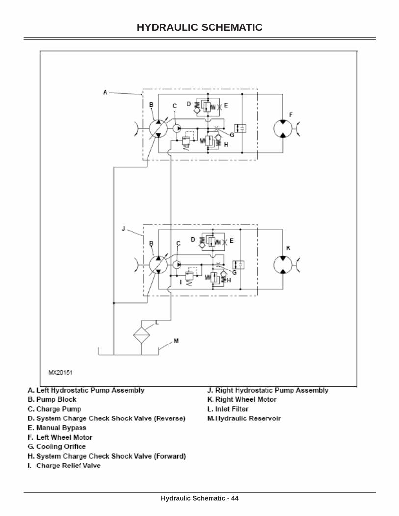
HYDRAULIC SCHEMATIC
Hydraulic Schematic - 44

NOTES
Notes - 45

MAIN FRAME ASSEMBLY
Frame Assembly - 46
96301910
9640166
9640034
9600226
9606016
TCU212651
M683422
2010061
9600012
9630012
9640404
2010191
2984301
9600442
96711510201150
2
9605268
Battery1
9640404
2010121
96301910
D281591
03H18322
9680874
96711510
2013631
037313001
2012041
037312001
9600274
9600314
2012021
9606016
9600226
1811481
2011942
2013321
9601136
1351394
96301910
9671926
2519071
2006581
9640034
2013291

MAIN FRAME ASSEMBLY
Frame Assembly - 47
PART NO QTY DESCRIPTIOND28159 1 STRIP, BATTERY INSULATORM68342 2 CLAMP, HOSE (RED) #
TCU21265 1 HOSE, 1/4" ID LOW PERM FUEL 5003H1832 2 BOLT, 5/16-18 X 6.00 CRG 2 Y135139 4 BOLT, 1/2 X 1.06 X 3/8-16 SLD 5 Y181148 1 CABLE, BATTERY STARTER - 48"191832 1 BATTERY, 12V-U1-CCA270MIN200658 1 PIN, CVS SPG 3/8" YOKE SPEC Y201006 1 TANK, FUEL SCORPION ASSEMBLY201012 1 WLDT, RESERVIOR GUARD201019 1 CABLE, BATTERY - 25" GROUND201363 1 CONSOLE BATTERY BRACKET201329 1 SHIELD, LH PUMP201332 1 SHIELD, RH PUMP
03731200 1 SHIELD, RH MOTOR03731300 1 SHIELD, LH MOTOR
201150 2 ASSY, TIRE/WHL 18/6.5X8 SLVR298430 1 SHIELD, ENGINE201194 2 ROD, CONTROL 5/16 X 22.75 Y201202 1 RH CAST WEIGHT MACHINED201204 1 LH CAST WEIGHT MACHINED251907 1 YOKE, 3/8-24 RH ADJUSTABLE960001 2 BOLT, 1/4-20 X .750 HEX 5 Y960022 6 BOLT, 5/16-18 X .750 HEX 5 Y960027 4 BOLT, 5/16-18 X 2.00 HEX 5 Y960031 4 BOLT, 5/16-18 X 3.00 HEX 5 Y960044 2 BOLT, 3/8-16 X 1.00 FGH 8 Y960113 6 BOLT, 1/2-13 X 1.25 HEX 5 Y960526 8 NUT, 1/2-20 LUG C960601 6 WASHER, .313 MED SPRG LOCK Y963001 2 BOLT, 1/4-20 X .625 WSH Y963019 10 BOLT, 3/8-16 X 1.00 CRG 5 SN Y964003 4 NUT, 5/16-24 STD HEX GR5 Y964016 6 LOCKNUT, 3/8-16 WHIZ Y964040 4 LOCKNUT, 1/4-20 WHIZ Y967115 10 LOCKNUT, 5/16-18 NYLOC Y967192 6 LOCKNUT, 1/2-13 WHIZ GR5 Y968087 4 LOCKNUT, 3/8-16 NYLOC Y
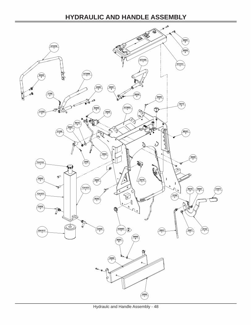
HYDRAULIC AND HANDLE ASSEMBLY
Hydraulc and Handle Assembly - 48
9600018
9606006
037315121
037307001
9630204
037309001
D130282
1210803 964048
4
9600018
1027703
9600022
9640484
1806401
D133081
34H601
9680876
9607024
1808421
TCA153731
TCA151221
9600462
D240282
GDA101371
D240282
037288301
033840071
9630531
9680876
2007051
9600002
M634313
2006151
2006711
2010221
1210803
9680876
9607024
D180791
037310001
9600018
9606006
2006061
2006901
2
2038932
TCA153731

HYDRAULIC AND HANDLE ASSEMBLY
Hydraulc and Handle Assembly - 49
PART NO QTY DESCRIPTIOND13028 2 SWIVEL ADJUSTERD13308 1 BASE, LOCK LEVER YD13309 1 LEVER, LOCK YD18079 1 GRIP, PVC .250 X 1.00 X 3.63D24020 3 SCREW, 8-32X .50 PAN PHL YD24028 1 FTG, 90 9/16 MOR X 3/8 HOSED14196 1 FITTING
GDA10137 1 FILTER, OILM63431 3 NUT, 8-32 ELASTIC STOP
TCA15122 1 CAP, FILLER OIL203893 2 WLDT, PIVOT ROD Y
TCA15373 1 WLDT, RESERVIOR HYDRAULIC102770 3 RELAY, ISO MINI ELEC.111910 3 CABLE TIE, .15 X 8.50121080 3 PIN, HAR .091 X 1.63 5/16-1/2 Y180640 1 SOLENOID, 12 V STARTER180842 1 CABLE, 12" STARTER200116 4 BRG, FLG .500X.620X.500 BRNZ200606 1 PAD, THIGH200615 1 LINK. BRAKE Y
03731512 1 CONTROL PANEL S/O03730751 1 HANDLE, SUPPORT
200671 1 BUSHING, BRAKE PIVOT Y200690 1 WLDT, THIGH PAD BRACKET200705 1 SWITCH, NO-NO-NC GREY PLUNGER201022 1 BRAKE LEVER, OFFSET
03728830 1 WLDT, CONSOLE 3403731000 1 WLDT, RH CONTROL LEVER w/Grip03730900 1 WLDT, LH CONTROL LEVER w/Grip
201197 1 HARNESS, WIRINGD24028 1 FTG, 90 9/16 MOR X 3/8 HOSE34H60 1 PIN, SPRING960000 2 BOLT, 1/4-20 X .500 HEX 5 Y960001 7 BOLT, 1/4-20 X .750 HEX 5 Y960002 2 BOLT, 1/4-20 X 1.00 HEX 5 Y960046 2 BOLT, 3/8-16 X 1.00 HEX 5 Y960500 2 NUT, 1/4-20 STD HEX GR5 Y960600 6 WASHER, .250 MED SPRG LOCK Y960702 4 WASHER, .375 REG FLAT Y963020 4 BOLT, 3/8-16 X 1.00 CRG 5 Y963053 1 BOLT, 3/8-16 X 1.25 CRG 5 Y964048 3 LOCKNUT, 1/4-20 NYLOC Y968087 6 LOCKNUT, 3/8-16 NYLOC Y

ENGINE, HYDRAULIC AND MAINFRAME ASSEMBLY
Engine, Hydraulic And Mainframe Assembly - 50
D142521
9606021
D180561
2006651
2003181
9671156
9600521
9640011
4034901
1500521
1911792
D180711
2011431
1911792
D183141
9600491
96808712
96808712
9607023
96808712
9630332
9605021
1119104
2007691
2311042
TCA150782
2316472
96004610
2009592
24M7158211H237
2
2010271
TCA162401
9671156
9670341
9671156
9630534
96808712
D142132
TCA153162
D180672
2010251
9671551
9640132
D381281
2007701
9600551
d180381
037347611
9673402
M1175542
TCA150782
GDA100041
9599952
9630202
9600261
9600253
D141602
2006661
9600222
9600781
2310462
2010914231046
2
2010914
2012061
9599952
1119104
96808712
9607023
D181451
M868632
DT53321
D1837912
1119104
2012061
2009582
9673708
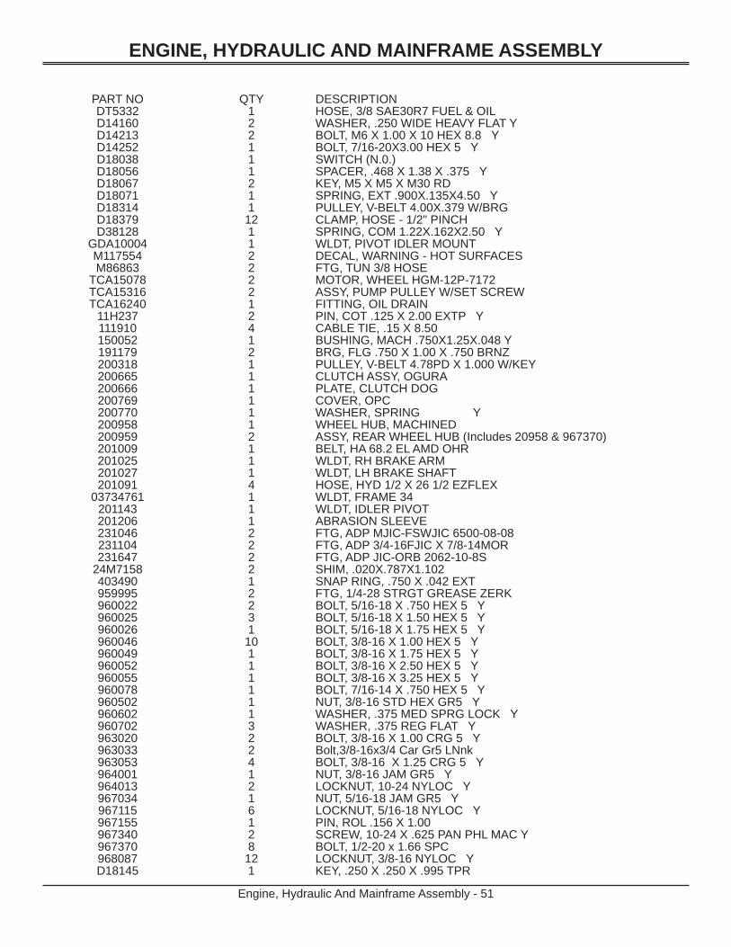
ENGINE, HYDRAULIC AND MAINFRAME ASSEMBLY
Engine, Hydraulic And Mainframe Assembly - 51
PART NO QTY DESCRIPTIONDT5332 1 HOSE, 3/8 SAE30R7 FUEL & OILD14160 2 WASHER, .250 WIDE HEAVY FLAT YD14213 2 BOLT, M6 X 1.00 X 10 HEX 8.8 YD14252 1 BOLT, 7/16-20X3.00 HEX 5 YD18038 1 SWITCH (N.0.)D18056 1 SPACER, .468 X 1.38 X .375 YD18067 2 KEY, M5 X M5 X M30 RDD18071 1 SPRING, EXT .900X.135X4.50 YD18314 1 PULLEY, V-BELT 4.00X.379 W/BRGD18379 12 CLAMP, HOSE - 1/2" PINCHD38128 1 SPRING, COM 1.22X.162X2.50 Y
GDA10004 1 WLDT, PIVOT IDLER MOUNTM117554 2 DECAL, WARNING - HOT SURFACESM86863 2 FTG, TUN 3/8 HOSE
TCA15078 2 MOTOR, WHEEL HGM-12P-7172TCA15316 2 ASSY, PUMP PULLEY W/SET SCREWTCA16240 1 FITTING, OIL DRAIN
11H237 2 PIN, COT .125 X 2.00 EXTP Y111910 4 CABLE TIE, .15 X 8.50150052 1 BUSHING, MACH .750X1.25X.048 Y191179 2 BRG, FLG .750 X 1.00 X .750 BRNZ200318 1 PULLEY, V-BELT 4.78PD X 1.000 W/KEY200665 1 CLUTCH ASSY, OGURA200666 1 PLATE, CLUTCH DOG200769 1 COVER, OPC200770 1 WASHER, SPRING Y200958 1 WHEEL HUB, MACHINED200959 2 ASSY, REAR WHEEL HUB (Includes 20958 & 967370)201009 1 BELT, HA 68.2 EL AMD OHR201025 1 WLDT, RH BRAKE ARM201027 1 WLDT, LH BRAKE SHAFT 201091 4 HOSE, HYD 1/2 X 26 1/2 EZFLEX
03734761 1 WLDT, FRAME 34201143 1 WLDT, IDLER PIVOT201206 1 ABRASION SLEEVE231046 2 FTG, ADP MJIC-FSWJIC 6500-08-08231104 2 FTG, ADP 3/4-16FJIC X 7/8-14MOR231647 2 FTG, ADP JIC-ORB 2062-10-8S
24M7158 2 SHIM, .020X.787X1.102403490 1 SNAP RING, .750 X .042 EXT959995 2 FTG, 1/4-28 STRGT GREASE ZERK960022 2 BOLT, 5/16-18 X .750 HEX 5 Y960025 3 BOLT, 5/16-18 X 1.50 HEX 5 Y960026 1 BOLT, 5/16-18 X 1.75 HEX 5 Y960046 10 BOLT, 3/8-16 X 1.00 HEX 5 Y960049 1 BOLT, 3/8-16 X 1.75 HEX 5 Y960052 1 BOLT, 3/8-16 X 2.50 HEX 5 Y960055 1 BOLT, 3/8-16 X 3.25 HEX 5 Y960078 1 BOLT, 7/16-14 X .750 HEX 5 Y960502 1 NUT, 3/8-16 STD HEX GR5 Y960602 1 WASHER, .375 MED SPRG LOCK Y960702 3 WASHER, .375 REG FLAT Y963020 2 BOLT, 3/8-16 X 1.00 CRG 5 Y963033 2 Bolt,3/8-16x3/4 Car Gr5 LNnk963053 4 BOLT, 3/8-16 X 1.25 CRG 5 Y964001 1 NUT, 3/8-16 JAM GR5 Y964013 2 LOCKNUT, 10-24 NYLOC Y967034 1 NUT, 5/16-18 JAM GR5 Y967115 6 LOCKNUT, 5/16-18 NYLOC Y967155 1 PIN, ROL .156 X 1.00967340 2 SCREW, 10-24 X .625 PAN PHL MAC Y967370 8 BOLT, 1/2-20 x 1.66 SPC968087 12 LOCKNUT, 3/8-16 NYLOC YD18145 1 KEY, .250 X .250 X .995 TPR

FOOT PLATE/CONSOLE COMPONENTS
Foot Plate/Console Components - 52
FOOT PLATE COMPONENTS
CONSOLE COMPONENTS
9600014
2006191
2007671
9630742
2011361
2006552
9671152
9607012
2006931
9680874
9630194
9640484
TCU16481
TCU14840
D18021
1806201
2006071
1365741 192296
1
D184271
D240202
TCA150511
M634312
14H8461
1056841

FOOT PLATE COMPONENTS
CONSOLE COMPONENTS
FOOT PLATE/CONSOLE COMPONENTS
Foot Plate/Console Components - 53
PART NO QTY DESCRIPTION200619 1 PLATE, PLATFORM TAB LH200655 2 BUMPER, MINER GBR-6200693 1 PLATE, PLATFORM TAB200767 1 ANCHOR, OPC201136 1 PLATFORM960001 4 BOLT, 1/4-20 X .750 HEX 5 Y960701 2 WASHER, .313 REG FLAT Y963019 4 BOLT, 3/8-16 X 1.00 CRG 5 SN Y963074 2 BOLT, 5/16-18 X 1.00 CRG 2 Y964048 4 LOCKNUT, 1/4-20 NYLOC Y967115 2 LOCKNUT, 5/16-18 NYLOC Y968087 4 LOCKNUT, 3/8-16 NYLOC Y
PART NO QTY DESCRIPTIOND18021 1 DECAL, THROTTLED18427 1 CABLE, CHOKED24020 2 SCREW, 8-32X .50 PAN PHL YM63431 2 NUT, 8-32 ELASTIC STOP
TCA15051 1 CABLE, THROTTLETCU14840 1 DECAL, GENERAL CAUTIONTCU16481 1 DECAL, PTO & KEY SWITCH
105684 1 KEY136574 1 SWITCH, PTO ENGAGEMENT14H846 1 NUT, 3/8 UNF HEX GR 5 ZN180620 1 SWITCH, KEY - 3 POSITION192296 1 METER, HOUR - LCD ALT. (ENM)
03731502 1 TOP, CONSOLE W/DECALS

DECK ASSEMBLY
Deck Assembly - 54
037330032
9673482
GDU102311
D180556
2002602
96004616
96401617
TCA163871
M1327681
H1411231
2011781
9680874
D180762
9680874
96401617
D230581
D180841
D130242
96050212
N2421891
2011451
9600511
D180321
9645011
9640221
D240192
9599951
4243901
D180762
2975111
M1193522
9640242
999538.5
TCU187441GDA10103
1
H1222071
9630951
9630193
GDU102301
D182091
037294031
2010101

DECK ASSEMBLY
Deck Assembly - 55
PART NO QTY DESCRIPTIOND13024 2 SPACER, 1.500X1.000X.510 YD18032 1 PULLEY, FLAT 5.0X.38 W/BRGD18055 6 WASHER, BLADED18076 2 BRG, FLG 1.00X1.25X1.00D18084 1 PULLEY, SPLINE SPINDLE OFFSETD18209 1 PULLEY, V-BELT 5.27X.990 W/SPLD24019 2 WASHER, .402X2.00X.055 FEND YD23058 1 J-BOLT, 3/8-16 X 4.00 Y
GDA10103 1 PIVOT, RETAINER WELDGDU10230 1 BLADE, 16.50 LO-LIFTGDU10231 1 BLADE, 18"H122207 1 NUT-1/4" FLANGE PREVAILING TORH141123 1 RETAINER #M132768 1 SPRING,CHUTE GUARDM119352 2 KNOB, LOCKINGN242189 1 SPRING, TENSION
TCA16387 1 CHUTE DISCHARGE ASST #TCU18744 1 WHEEL, GAGE
200260 2 ASSY, SPINDLE HOUSING201010 1 BELT, HB 80.3 EL AMD OHR201145 1 WLDT, IDLER ARM
03729403 1 WLDT, 34" DECK03733003 2 ASSY, FR WHEEL CASTER
297511 1 SHIELD, DECK 34201178 1 WLDT, IDLER PIVOT424390 1 SNAP RING, 1.00 X .042 EXT959995 1 FTG, 1/4-28 STRGT GREASE ZERK960046 16 BOLT, 3/8-16 X 1.00 HEX 5 Y960051 1 BOLT, 3/8-16 X 2.25 HEX 5 Y960502 12 NUT, 3/8-16 STD HEX GR5 Y963019 3 BOLT, 3/8-16 X 1.00 CRG 5 SN Y963095 1 BOLT, 1/4-20 X .750 CRG 5 Y964016 17 LOCKNUT, 3/8-16 WHIZ Y964022 1 LOCKNUT, 3/8-16 CROWN Y964501 1 WASHER, .406 X .813 X .065 FLAT Y964024 2 LOCKNUT, 3/4-16 CROWN Y967348 2 BOLT, 5/8-11 X 2.00 HEX 8 Y968087 4 LOCKNUT, 3/8-16 NYLOC Y999538 1 TRIM 1/4

WHEEL AND STRUT ASSEMBLY/PUMP COMPONENTS
Wheel and Strut Assembly/Pump Components - 56
PUMP COMPONENTS
WHEEL AND STRUT ASSEMBLY
2 2
2 2
1 1
6 6 3 3 4 4 8 8 5 5 7 7
9 9
1613971
D130081
D180762
2013081
D180762
1641454
2013111
9630111
2007781
9640001
1910491
9599951
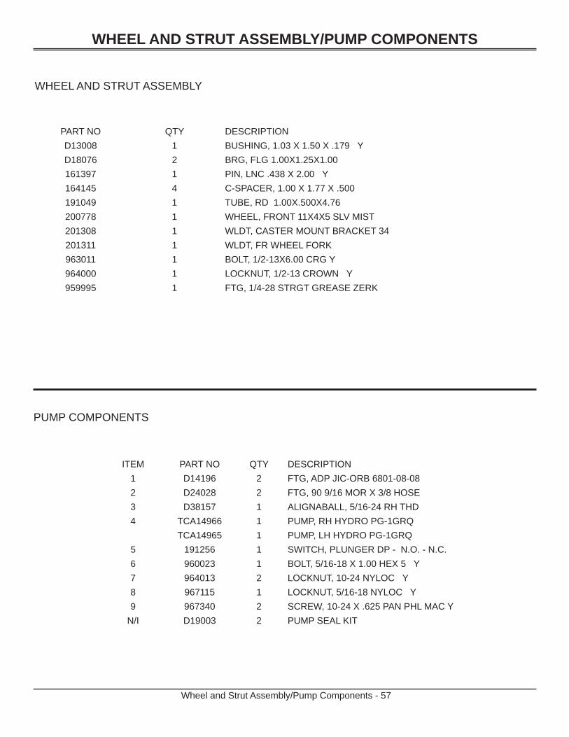
WHEEL AND STRUT ASSEMBLY
PUMP COMPONENTS
ITEM PART NO QTY DESCRIPTION1 D14196 2 FTG, ADP JIC-ORB 6801-08-082 D24028 2 FTG, 90 9/16 MOR X 3/8 HOSE3 D38157 1 ALIGNABALL, 5/16-24 RH THD4 TCA14966 1 PUMP, RH HYDRO PG-1GRQ
TCA14965 1 PUMP, LH HYDRO PG-1GRQ5 191256 1 SWITCH, PLUNGER DP - N.O. - N.C.6 960023 1 BOLT, 5/16-18 X 1.00 HEX 5 Y7 964013 2 LOCKNUT, 10-24 NYLOC Y8 967115 1 LOCKNUT, 5/16-18 NYLOC Y9 967340 2 SCREW, 10-24 X .625 PAN PHL MAC Y
N/I D19003 2 PUMP SEAL KIT
WHEEL AND STRUT ASSEMBLY/PUMP COMPONENTS
Wheel and Strut Assembly/Pump Components - 57
PART NO QTY DESCRIPTIOND13008 1 BUSHING, 1.03 X 1.50 X .179 YD18076 2 BRG, FLG 1.00X1.25X1.00161397 1 PIN, LNC .438 X 2.00 Y164145 4 C-SPACER, 1.00 X 1.77 X .500191049 1 TUBE, RD 1.00X.500X4.76200778 1 WHEEL, FRONT 11X4X5 SLV MIST201308 1 WLDT, CASTER MOUNT BRACKET 34201311 1 WLDT, FR WHEEL FORK963011 1 BOLT, 1/2-13X6.00 CRG Y964000 1 LOCKNUT, 1/2-13 CROWN Y959995 1 FTG, 1/4-28 STRGT GREASE ZERK
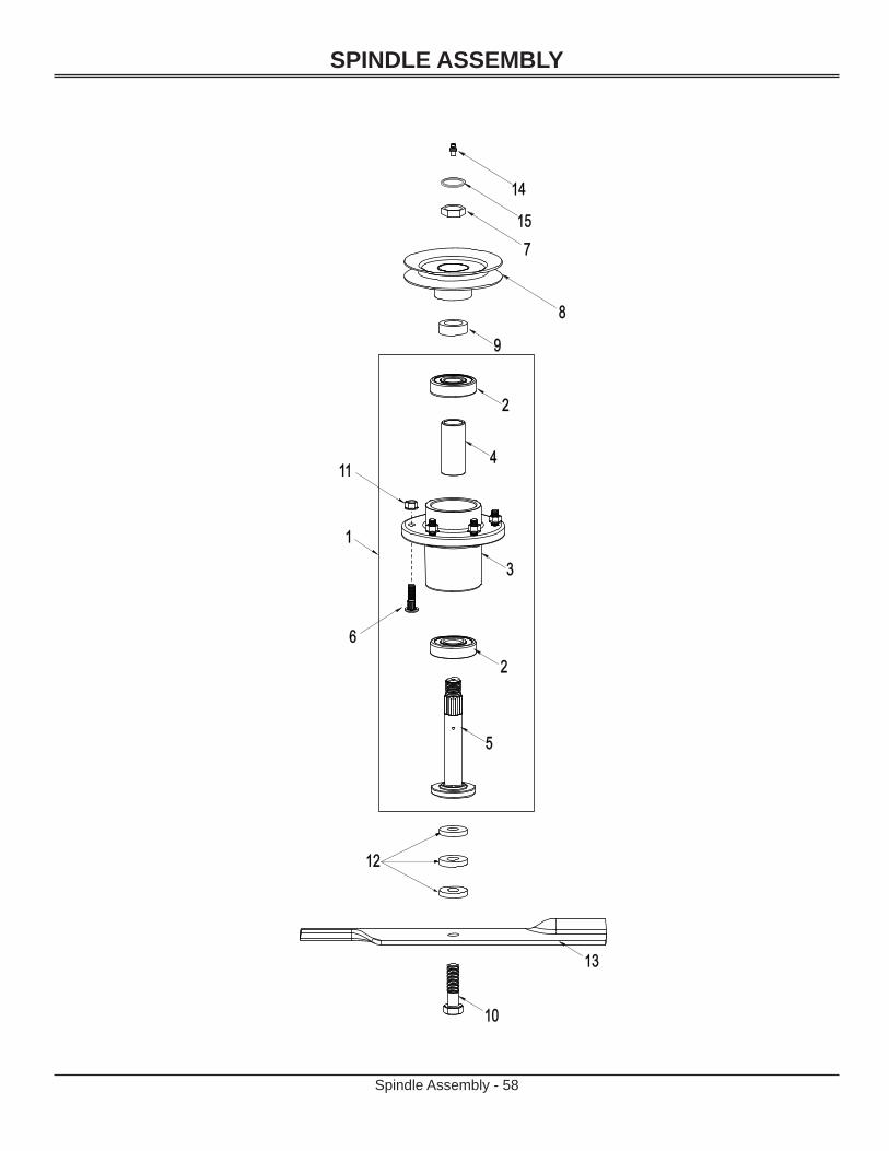
SPINDLE ASSEMBLY
Spindle Assembly - 58
14 14
15157 7
8 8
9 9
2 2
4 4
3 3
1 1
6 6
11 11
2 2
5 5
12 12
13 13
10 10

SPINDLE ASSEMBLY
Spindle Assembly - 59
ITEM PART NO QTY DESCRIPTION1 200262 1 Spindle Assembly - Includes items 2, 3, 4, 5, 6, 142 200046 2 Ball Bearing
3 200042 1 Housing4 200044 1 Spacer - 1.000 x 1.250 x 2.7725 200196 1 Shaft, Spindle6 200045 6 Bolt, 3/8-16 x 1.25 Rib7 964024 2 Nut, Pulley (Special)8 N/A 2 Pulley, Cutter Housing - See Mower Assembly Pages9 D13024 2 Spacer, Pulley
10 967348 2 Bolt, Blade - 5/8-11 x 2.00 Grade 811 960502 12 Nut, 3/8-16 Std Hex Gr512 D18055 6 Spacer, Blade Bolt13 GDU10231 1 18.0" Blade, LH Deck
GDU10230 1 16.5” Blade, RH Deck14 959995 1 Zerk, Grease S/O15 200263 1 Retainer Nut
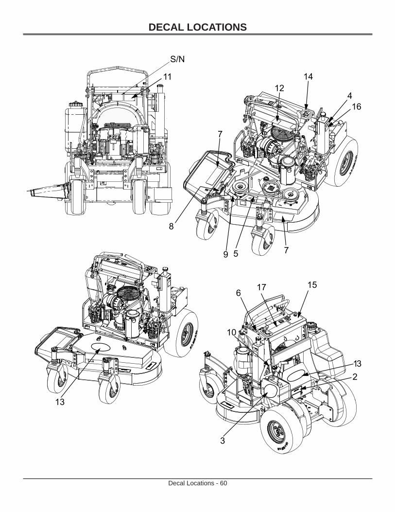
DECAL LOCATIONS
Decal Locations - 60

DECAL LOCATIONS
Decal Locations - 61
WARNINGShield Missing.DO NOT Operate.
200037
MAY BE COVERED BY ONEOR MORE OF THE FOLLOWING PATENT(S):5,343,678; 5,507,138; 5,600,944;5,765,347; 5,964,082; 6,085,504;6,094,897; 6,189,305; 6,189,304;6,404,515; 6,625,965; 6,862,872
ONPULL
OFFPUSH
BLADE
CAUTIONBEFORE OPERATINGREAD OPERATORS
MANUAL ANDSAFETY INSTRUCTIONS
STOP
BELT ROUTING
201043
Not Shown.

EverRideAn Ariens Company655 West Ryan StreetBrillion, WI 54110-1072920-756-2141Fax 920-756-2407www.ariens.com