Embed Size (px)
Citation preview

Science Directorate Instrument Technologies division
Neutron Chopper GroupTAP 5-2014
Requirements of Instrument suite
Iain SuttonNeutron Chopper Group Leader
www.europeanspallationsource.se23 April, 2014
A preliminary review of chopper systems included in current proposals
Proposal round 2013
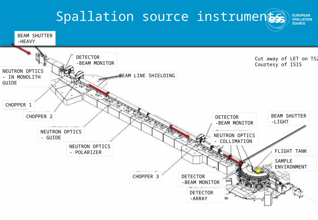
Spallation source instruments
• PHOTO ISIS Instrument• - overlay schematic
components
CHOPPER 3
CHOPPER 1
CHOPPER 2
NEUTRON OPTICS- GUIDE
NEUTRON OPTICS- POLARIZER
NEUTRON OPTICS- COLLIMATION
DETECTOR-ARRAY
DETECTOR-BEAM MONITOR
DETECTOR-BEAM MONITOR
FLIGHT TANK
BEAM LINE SHIELDING
SAMPLE ENVIRONMENT
DETECTOR-BEAM MONITOR
NEUTRON OPTICS- IN MONOLITH GUIDE
BEAM SHUTTER-LIGHT
BEAM SHUTTER-HEAVY
Cut away of LET on TS2Courtesy of ISIS

BEAM
PO
RT
# 1-2 3-4
BW S
ELEC
TIO
N
FUN
CTIO
NN
OTE
SNMX
GU
IDE
2PA-
02 (F
TF)
14H
z, D
700
L 20 50 156
2PA-
02 (F
TF)
BW S
ELEC
TIO
N14
Hz,
D70
0
GU
IDE
GU
IDE
Status: P1-P.DesignChopper system schematic
EQUIP ACCESS ZONECLASS : BLACK
EQUIP ACCESS ZONECLASS : GREEN
Sector: W Beam-port: W12

2PA-
01-M
-350
(CR)
BEAM
PO
RT
GU
IDE
GU
IDE
# 1-2 3-4 5 6-7 8-9
PULS
E SH
APIN
G
FUN
CTIO
NN
OTE
SCS/ VOR Phase 0: ProposalSchematic
PA-0
2 (-
M-1
4)
GU
IDE
MO
NO
CHRO
MAT
OR
PHAS
E(D
) / C
O
RRM
BAN
D W
IDTH
2PA-
01-M
-350
(CR)
2PA-
01-M
-!$)
(FTF
)
2PA-
01-M
-400
(CR)
COMMON SHIELDING
SHU
TTER
SHU
TTER
POSS
IBLE
SH
UTT
ER
POSI
TIO
N
POSS
IBLE
SH
UTT
ER
POSI
TIO
N
L 8 16-16.05
Sector: Beam port: NA

BEAM
PO
RT
7-14
Hz,
D70
0
# 1-2 3 -4 5 6-7 8 9-10 11
WAV
ELEN
GTH
BAN
D
DEF
ININ
G
FUN
CTIO
NN
OTE
SRF/ FREIA v2.0
GU
IDE
FRAM
E O
VERL
AP
L 6.5/6.6 7.1/7.5 8,5 10/10.1 11.1 15 15,6 252P
A-02
(FTF
)
PA-0
2 (D
C)
2PA-
02 (F
TF)
PA-0
2 (D
C)
GU
IDE
GU
IDE
GU
IDE
WAV
ELEN
GTH
BAN
D
DEF
ININ
G
WAV
ELEN
GTH
BAN
D
DEF
ININ
G
FRAM
E O
VERL
AP
FRAM
E O
VERL
AP
PULS
E SH
APIN
G
7-14
Hz,
D13
00
7-14
Hz,
D13
00
56H
z, D
1300
56H
z, D
1300
42H
z, D
1300
28H
z, D
1500
EQUIPT ACCESS CLASS : ORANGE EQUIPT ACCESS CLASS : GREEN
GU
IDE
2PA-
02 (U
O)
2PA-
02 (F
TF)
PA-0
2 (D
C)
GU
IDE
GU
IDE
Status: P0-ProposalSchematic Sector: E/N Beam-port: ?

BEAM
PO
RT
PA-0
2 (D
C)
GU
IDE
GU
IDE
280H
z, D
700
# 1 2 3 4 5 6 7
PULS
E SH
APIN
G
(CT1
)
FUN
CTIO
NN
OTE
SPD/ HEIMDAL Status: P0-ProposalSchematic
2PA-
02 (F
TF)
GU
IDE
FRAM
E O
VERL
AP
(CT3
)
L 6,5 7 9 13 78 78,6 S = 169m
PULS
E SE
LECT
ION
(C
T2)
PA-0
2 (D
C)
14H
z, D
1360
14H
z, D
700
PA-0
2 (D
C)
BAN
D D
EFIN
ITIO
N
(CC1
)14
Hz,
D12
80
FRAM
E O
VERL
AP
(CC3
)14
Hz,
D12
80
PA-02 (DC)
FRAM
E O
VERL
AP
(CC3
)14
Hz,
D
1280
EQUIPT ACCESS CLASS : BLACK
PA-02 (DC)
EQUIPT ACCESS CLASS : TBD
BEAM
PO
RT
# 1-2 3-4 5 6-7 8-9 10-11 12-13 14-15 16-17 18-19
PPS
FUN
CTIO
NN
OTE
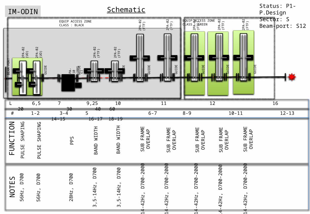
SIM-ODIN
28H
z, D
700
L 6,5 7 9,25 10 11 12 16 20 30 40 60
2PA-
02 (F
TF)
BAN
D W
IDTH
GU
IDE
GU
IDE
PA-1
0 (P
PSc)
2PA-
02 (F
TF)
2PA-
02 (F
TF)
2PA-
02 (U
O)
2PA-
02 (U
O)
PULS
E SH
APIN
G
PULS
E SH
APIN
G
56H
z, D
700
BAN
D W
IDTH
56H
z, D
700
3,5-
14H
z, D
700
3,5-
14H
z, D
700
2PA-
02 (F
TF)
2PA-
02 (F
TF)
2PA-
02 (F
TF)
SUB
FRAM
E O
VERL
AP
SUB
FRAM
E O
VERL
AP
SUB
FRAM
E O
VERL
AP
SUB
FRAM
E O
VERL
AP
14-4
2Hz,
D70
0-20
00
14-4
2Hz,
D70
0-20
00
2PA-
02 (F
TF)
SUB
FRAM
E O
VERL
AP
14-4
2Hz,
D70
0-20
00
14-4
2Hz,
D70
0-20
00
14-4
2Hz,
D70
0-20
00
GU
IDE
GU
IDE
GU
IDE
GU
IDE
GU
IDE
GU
IDE
Status: P1-P.DesignSector: S Beam-port: S12
SchematicEQUIP ACCESS ZONECLASS : BLACK
EQUIP ACCESS ZONECLASS : GREEN

9
SUMMARY

10
A Summary of Choppersfor 22 Instruments, based on 3+16 instrument concepts
22 Instruments = 150 – 160
11
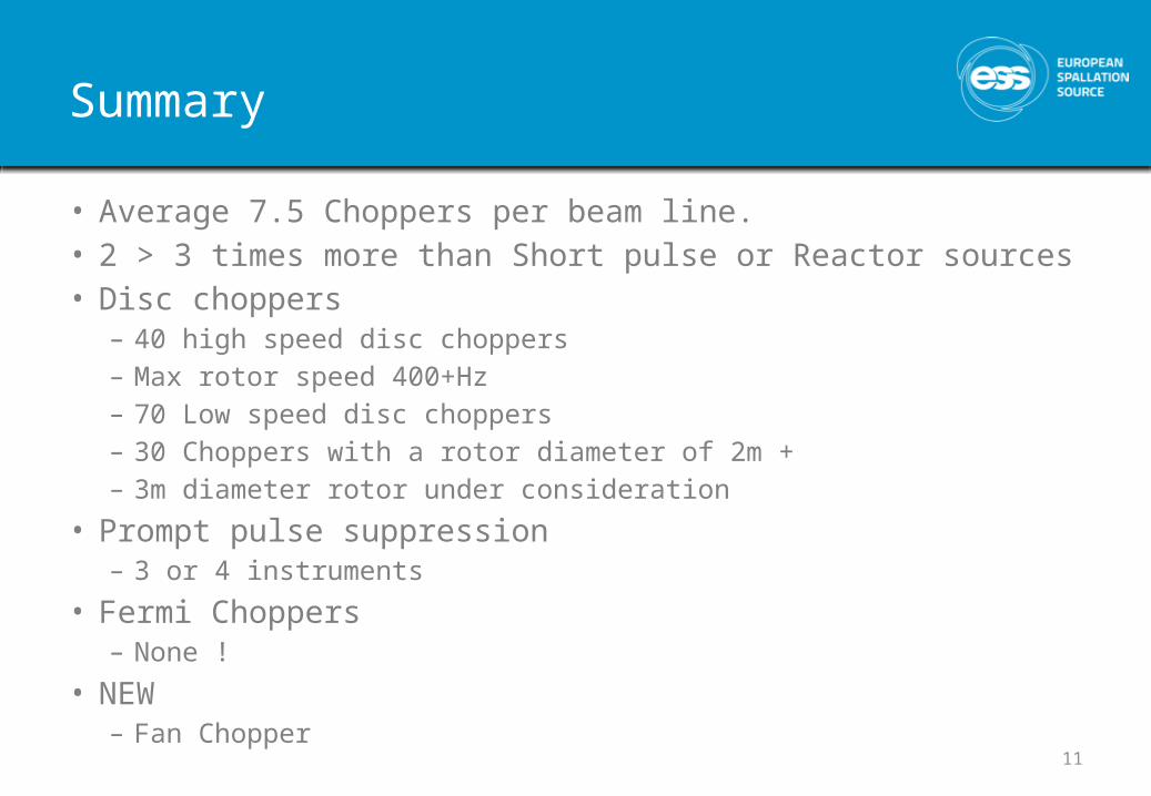
Summary
• Average 7.5 Choppers per beam line.• 2 > 3 times more than Short pulse or Reactor sources• Disc choppers
– 40 high speed disc choppers– Max rotor speed 400+Hz– 70 Low speed disc choppers– 30 Choppers with a rotor diameter of 2m +– 3m diameter rotor under consideration
• Prompt pulse suppression– 3 or 4 instruments
• Fermi Choppers– None !
• NEW– Fan Chopper

Chopper performance
PA-2-H-C PE-10-V-MPA-5-H-S PA-1-H-M PE-5-V-M

A suite of Choppers for ESS
Preliminary estimations

14

15
A Suite of Choppers… for 16 Instruments,based on current instrument concepts
16 Instruments ~ 120 axis
LOW SPEED
(48
)PA
-02
(-M
-14)
(20)
INTERMEDIATE SPEED
PA-0
2 (-
M-1
4)
HIGH SPEED
(18)
2PA-
02 (U
O)
LARGE ROTOR
(24)
2PA-
02 (F
TF)
(3)
FAN PPSc
(6)
PA-1
0 (P
PSc)
‘Tendency’
• No ‘Fermi’ Choppers– Except Tempis fugit ‘rotating mono array’
• The ‘Fan Chopper’– Several groups now expressing interest…
• Requests for 3m rotors is declining• Request for a ‘compact’ PPS chopper• Requests for ‘movable’ choppers– Variable separation– Out of beam

Platform 1Disc chopper – Small rotor – Low speed
DC-SR (50-70)
Key requirements• Rotation speed: Low ( 7 - 96 Hz)• Openings: Large• Attenuation at short wavelengths• High reliability in radiation environment• Low lifetime cost
Principal characteristics• Type: PA-1-H- (horizontal axis disc) • Rotors : Simple + Robust • Diameter: 600-1000mm
Enabling Technologies .• Rotors materials: Metallic • Bearings: Magnetic
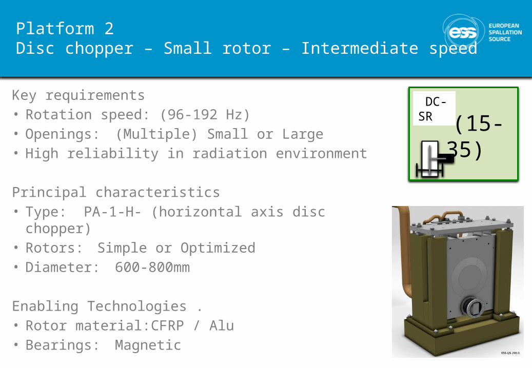
Platform 2Disc chopper – Small rotor – Intermediate speed
DC-SR (15-35)
Key requirements• Rotation speed: (96-192 Hz)• Openings: (Multiple) Small or Large• High reliability in radiation environment
Principal characteristics• Type: PA-1-H- (horizontal axis disc chopper) • Rotors: Simple or Optimized• Diameter: 600-800mm
Enabling Technologies .• Rotor material: CFRP / Alu • Bearings: Magnetic

Platform 3:Disc chopper – Small rotor – High speed
Key requirements• Rotation speed: 192- 400+ Hz• Openings: (Multiple) Small • Minimal guide interruption• High reliability in radiation environment
Principal characteristics• Type : PA-1-H- (horizontal axis disc) • Rotors design: Optimised• Diameter : 600-700mm
Enabling Technologies .• Rotor material: CFRP / Ti / MMC• Bearings: Magnetic
DC-SR-VHP
(25-35)
2.PA-1-H-M

Platform 4:Disc chopper – Large rotor
DC-LR
(25-35)
Key requirements• Rotation speed: (7 - 56 Hz)• Openings: Multiple V.Large, Asymmetric• High closing speed• High reliability in radiation environment
Principal characteristics• Type: PA-1-H- (horizontal axis disc chopper) • Rotors: Optimized • Diameter: 1200 - 2000mm
Enabling Technologies .• Rotor material: CFRP / Alu • Bearings: Magnetic or Contact
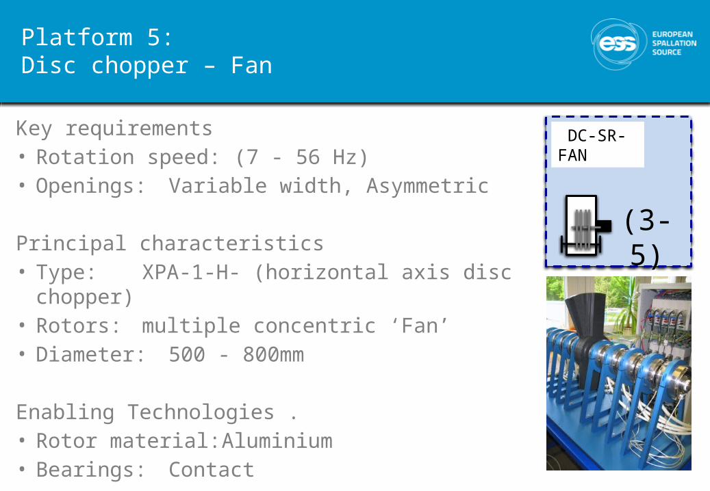
Platform 5:Disc chopper – Fan
DC-SR-FAN
(3-5)
Key requirements• Rotation speed: (7 - 56 Hz)• Openings: Variable width, Asymmetric
Principal characteristics• Type: XPA-1-H- (horizontal axis disc chopper) • Rotors: multiple concentric ‘Fan’ • Diameter: 500 - 800mm
Enabling Technologies .• Rotor material: Aluminium • Bearings: Contact

Platform 6:Prompt pulse suppression chopper PPSc
PPSc
(4-8)
PA-1
0 (P
PSc)
Key requirements• Rotation speed: (7 - 56 Hz)• Closure: 3ms, Symmetric or Asymmetric • Attenuation : 90% @ Prompt pulse energies• Extreme radiation resistance
Principal characteristics• Type: PA-10-H- (horizontal axis chopper) • Rotors: 300 – 400 thick , single or double• Diameter: 500 - 600mm
Enabling Technologies .• Rotor material: Nickel alloy / Tungsten • Bearings: Magnetic

23
Platform 56‘Instrument specific developments’
• Support the development of ‘one off, instrument specific choppers’ which can not be achieved within platform approach.
• Support in integration into ESS systems – Control– Support systems– Pit systems
• Active collaboration in engineering design process and decisions.
• Examples– PST– Compact PPSc

24
MEETING FACILITY GOALS
Best service – Least cost
Reliability/Availability/ServiceabilityLife time cost

Balancing actAggressive operating schedule
(225 beam days)
Complex instruments(130+ choppers)
Availability > 95% (?)

Instrument suite modelIN
STRU
MEN
T 01
<-------------- 15 degree ------------- >IN
STRUM
ENT 03
< 5 degree >
INSTRU
MEN
T 02
TARGET MONOLITH

Serviceability
Lateral shielding Access levels
Mean Time To Repair (MTTR)
• Time to access (zone dependent)• Time to repair (equipment dependent)

SNS Beam line/Group totals & availability – FY13 thru June 2, 2013
“SNS neutron beamline/instrument availability is about 89%”
1 2 3 4 5 6 7 8 9 10 11 12 13 14 15 16 17 18 19 200
1
2
3
4
5
6
7
Beam
inte
rrup
tions
Cycles (Normalized to 35 day)
CAUSE OF STOPPAGEBLUE Chopper systemRED Other componentGREEN At request of I.S.
~ 3 ‘significant’ interruption per 100 beam days +3.5 uses of shutters to effect ‘running repairs’
Instrument suite downtimeData from ISIS, TS1 & 2 (2007-2011)
Instrument suite downtime

RELIABILITYInstrument related causes of beam loss
Source: ISISNote: excluding - Sample environments, Computing & Motion control
Causes often requiring access within heavy shielding for repair
Causes not requiring access within heavy shielding for repair
Instrument MTBF ~598 daysInstrument suite MTBF ~35 days

Simulated ESS Instrument availability(averaged across suite )
option A /B Option C/D Option E50
55
60
65
70
75
80
85
90
95
100
66.4
93.4
8179.8
93.4
89
225 BD 215 BD + 4 Short breaks

ESS Equipment reliability targets
Working hours shutter optionReliability
Classification MTBF MTBR Name Distribution Typical components
Class A72000
(10-15yrs) 36Very reliable - quick
fix 70%Std choppers, Vacuum systems, Fixed
Collimation, Std optics
Class B 72000 168Very reliable – slow
fix 10%Special Choppers
Special optics
Class C3600
(8-12mnths) 36 Reliable – quick fix 15%diaphragms
Class D 3600 136 Reliable – slow fix 5%
Note
These figures concern only
Equipment installed within the common shielding area (radius 24m)Equipment presenting a significant risk of breakdown - ie no supports, shieldingEquipment critical to instrument performance - options and non essentials have been excluded

32
MEETING PROJECT GOALS
Requirements from a different set of stakeholders …

33
Project Drivers
• Raising Performance– Neutronic performance– Availability
• Reducing Costs– Procurement– Operations
• In-kind– Harness experience– Maximise contribution– Equitable distribution

34
EARLY SUCCESS
• Success will be measured early (within 3 years) • Tranche Instruments must be receiving users and
publishing major papers by 2021 ….
Priority Trinity• Construction • Commissioning • Early Operations

2014 2015 2016 2017 2018 2019 2020 2021 2022 2023 2024 2025 2026 2027 2028
Operations Schedule
#1
#2
#3
#4
#5
#6
#7
#8
#9
#10
#11
#12
#13
#14
#15
#16
Initial Design Final Design Procurement & Fabrication
Construction Installation Cold Commissioning Hot Commissioning
1st N
eutr
ons
Instrument projects overview

Initial Design Final Design Procurement & Fabrication
Construction Installation Cold Commissioning Hot Commissioning
1st N
eutr
ons
On site Installation
Delivery, Integration & Test
Procurement
Development
Commissioning Interventions
Target Operations Schedule
Chopper & InstrumentsThe ‘first 3’
#1
#2
#3
T-60m T-48m T-36m T-24m T-12m T0

HOW MANY & WHENPeriod Phase PPS Disc Fermi
2013-2016 Technologies development 4 3 12017-2019 Build program ‘Day 1 suite’ 2 35+ 32020-2025 Build program ‘Full suite’ 4 85+ 62025 > Total choppers in service 6 125 10
2013-2016 2017-2019 2020-2025

38
THE END
Thank you for you attention