Embed Size (px)
Citation preview
5-1
5. INSTRUMENT SYSTEMS
5.1 INTRODUCTION
Instrument Systems will deliver the technical scope required to produce eight neutron scattering instrument end stations. This includes (1) the infrastructure to transport the neutrons from the moderator face to the sample position and to shape, manipulate, and shield the neutron beam as required along the incident flight path and (2) the instrument end station and its associated shielding, mechanical components, neutron detectors, data acquisition system, and initial suite of sample environment equipment. By the conclusion of the project, these eight instruments will be ready to accept neutron beams and proceed with their commissioning.
5.2 INSTRUMENT PLANNING SUITE
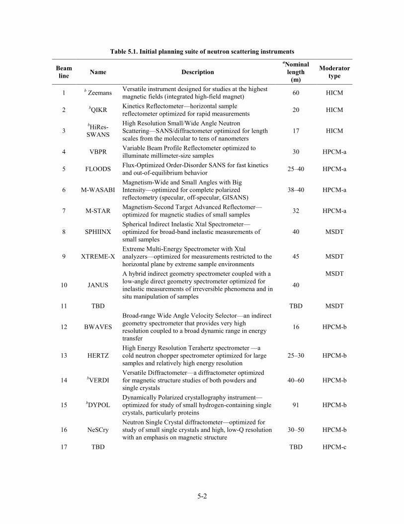
A number of instruments have been included in the initial STS scoping exercise to explore the diversity of source parameters and geometries required, particularly as regards required moderator performance. These initial instrument concepts represent the outcome of a number of working groups seeking to address scientific challenges that were identified in four major workshops (2014). Further details can be found in Ref. [1]. This exercise led to the three-moderator configuration described in Sect. 4.3.2. Table 5.1 lists these instruments, critical design parameters, and initial moderator requirements. The requirements span a larger number of moderators than can be supported by STS; therefore, those listed in the table represent something of a compromise across this instrument suite. The three moderators are
1. A high-intensity coupled moderator (HICM), nominally a 5×5 to 7×7 cm2 viewed face, coupled para-hydrogen moderator viewed from a single side.
2. A high-peak-brightness coupled para-hydrogen moderator (HPCM) with three viewed faces. Faces −a and −c are 3×3 cm2 viewed surfaces, and −b is a 3×6 cm2 viewed surface.
3. A multi-spectral decoupled moderator with 7×7 cm2 viewed surfaces. One side is ambient-temperature water (MSDT, T for thermal) and the second side cold para-hydrogen (MSDC, C for cold).
As instrument concepts mature, the selection of the optimum moderator is likely to change in some cases. Iteration between instrument needs and moderator design will probably modify the characteristics of the current moderator suite.
Instrument Systems will provide eight initial instruments as its project baseline, although STS will support a final instrument complement of 22. Eight instruments have been selected from the list in Table 5.1 (indicated by b) as representative of the highest performance and scientific impact. Note that final instrument selection will be a continuing process that engages the neutron scattering user community through the conceptual design phase of the project. Detailed science cases for these instruments have been described in Ref. [1]. This section presents additional details for these eight illustrative instruments.
5-2
Table 5.1. Initial planning suite of neutron scattering instruments
Beam line Name Description
aNominal length
(m)
Moderator type
1 b Zeemans Versatile instrument designed for studies at the highest magnetic fields (integrated high-field magnet) 60 HICM
2 bQIKR Kinetics Reflectometer—horizontal sample reflectometer optimized for rapid measurements 20 HICM
3 bHiRes-SWANS
High Resolution Small/Wide Angle Neutron Scattering—SANS/diffractometer optimized for length scales from the molecular to tens of nanometers
17 HICM
4 VBPR Variable Beam Profile Reflectometer optimized to illuminate millimeter-size samples 30 HPCM-a
5 FLOODS Flux-Optimized Order-Disorder SANS for fast kinetics and out-of-equilibrium behavior 25–40 HPCM-a
6 M-WASABI Magnetism-Wide and Small Angles with Big Intensity—optimized for complete polarized reflectometry (specular, off-specular, GISANS)
38–40 HPCM-a
7 M-STAR Magnetism-Second Target Advanced Reflectomer—optimized for magnetic studies of small samples 32 HPCM-a
8 SPHIINX Spherical Indirect Inelastic Xtal Spectrometer—optimized for broad-band inelastic measurements of small samples
40 MSDT
9 XTREME-X Extreme Multi-Energy Spectrometer with Xtal analyzers—optimized for measurements restricted to the horizontal plane by extreme sample environments
45 MSDT
10 JANUS
A hybrid indirect geometry spectrometer coupled with a low-angle direct geometry spectrometer optimized for inelastic measurements of irreversible phenomena and in situ manipulation of samples
40
MSDT
11 TBD TBD MSDT
12 BWAVES
Broad-range Wide Angle Velocity Selector—an indirect geometry spectrometer that provides very high resolution coupled to a broad dynamic range in energy transfer
16 HPCM-b
13 HERTZ High Energy Resolution Terahertz spectrometer —a cold neutron chopper spectrometer optimized for large samples and relatively high energy resolution
25–30 HPCM-b
14 bVERDI Versatile Diffractometer—a diffractometer optimized for magnetic structure studies of both powders and single crystals
40–60 HPCM-b
15 bDYPOL Dynamically Polarized crystallography instrument—optimized for study of small hydrogen-containing single crystals, particularly proteins
91 HPCM-b
16 NeSCry Neutron Single Crystal diffractometer—optimized for study of small single crystals and high, low-Q resolution with an emphasis on magnetic structure
30–50 HPCM-b
17 TBD TBD HPCM-c

5-3
Table 5.1. Initial planning suite of neutron scattering instruments (continued)
Beam line Name Description
aNominal length
(m)
Moderator type
18 EWALD Enhanced Wide-Angle Laue Diffractometer—a single-crystal diffractomter optimized for the study of small protein crystals
91 HPCM-c
19 bCHESS Chopper Spectrometer for Small Samples—a cold neutron chopper spectrometer optimized for the study of very small samples
25–30 HPCM-c
20 bMBARS Mica Backscattering Spectrometer—an indirect geometry, ultra-high-resolution spectrometer optimized for dynamics study of biological and soft matter samples
75 MSDC
21 bHighResPD High Resolution Powder Diffractometer—optimized for the highest resolution 120 MSDC
22 TBD TBD MSDC †Moderator-to-sample distance *Selected as one of eight instruments with additional detail
5.2.1 Zeemans
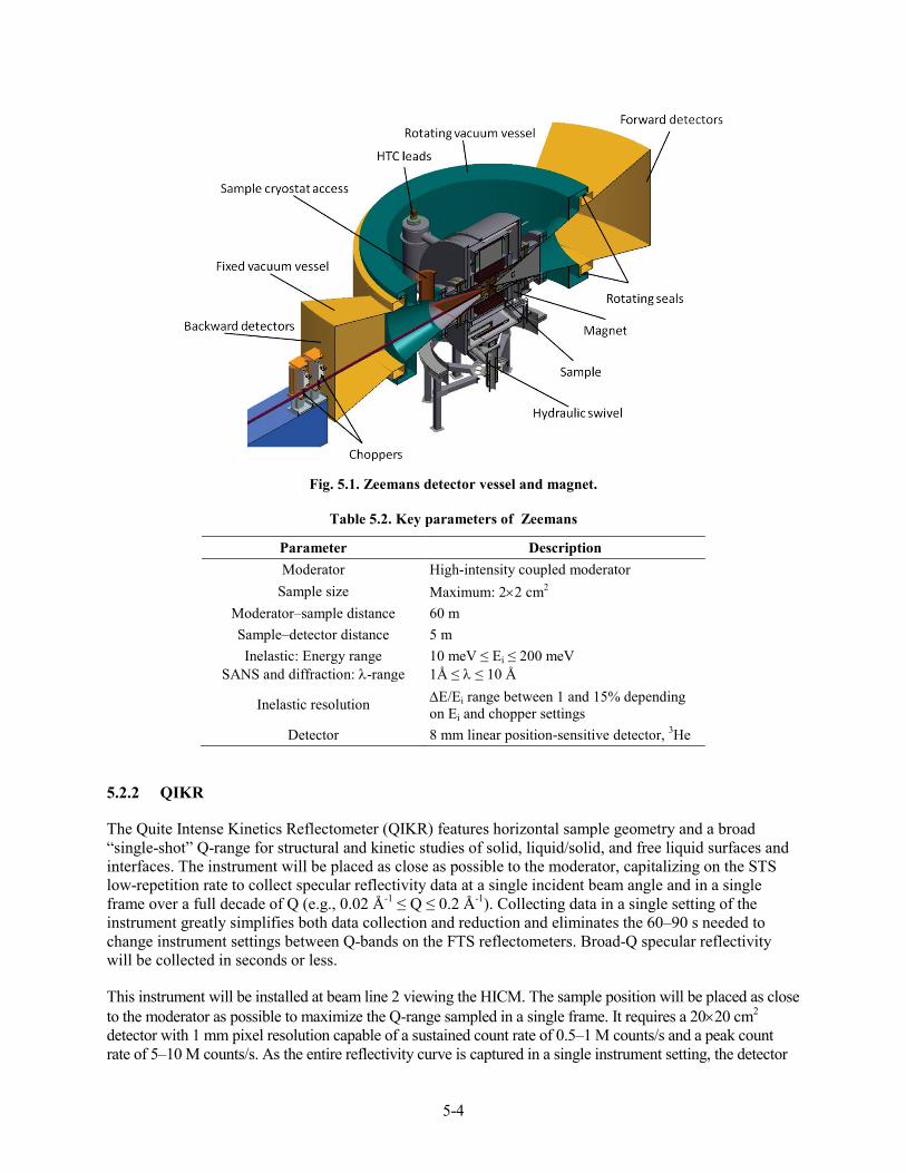
Zeemans is a versatile neutron scattering instrument with an integrated, horizontal high-field magnet and dedicated sample environment equipment specific to use with the magnet. It will be a facility reaching fields beyond 35 Tesla and offering a wide suite of neutron scattering techniques including spectroscopy, diffraction, reflectometry, and small-angle neutron scattering (SANS). The goal is to create the world center for high-magnetic-field neutron scattering.
The Zeemans instrument is envisioned as occupying neutron beam line 1 viewing the HICM. The beam line will be curved and may include a bender to avoid a direct line-of-sight view of the moderator. It will incorporate a number of neutron choppers and adjustable optical components (the last 5 m of the guide system) so as to tailor the neutron beam for individual scattering techniques. The instrument will include the capability to provide a polarized neutron beam and to perform analysis of the scattered beam polarization. A previous National Science Foundation–funded project resulted in a conceptual and engineering design for the superconducting magnet system that provides a head start for Zeemans.[2–4] Figure 5.1 shows the concept for the detector vessel and magnet that was developed in that project.
Zeemans requires significant infrastructure, including a dedicated building, helium liquification plant, dc power potentially up to 12 MW for the hybrid form of the magnet (highest field conditions), and sufficient cooling water (a dedicated cooling tower). The Zeemans building and associated utilities are described in Sect. 6, Conventional Facilities. The Zeemans instrument will require the development of specialized sample environment equipment that is compatible for use with high magnetic fields, matches the specific geometry of the instrument, and is capable of spanning the temperature range of 50 mK to 1000°C (likely with multiple devices). Table 5.2 lists key Zeemans instrument parameters.
5-4
Fig. 5.1. Zeemans detector vessel and magnet.
Table 5.2. Key parameters of Zeemans
Parameter Description Moderator High-intensity coupled moderator
Sample size Maximum: 2×2 cm2 Moderator–sample distance 60 m Sample–detector distance 5 m Inelastic: Energy range
SANS and diffraction: λ-range 10 meV ≤ Ei ≤ 200 meV 1Å ≤ λ ≤ 10 Å
Inelastic resolution ∆E/Ei range between 1 and 15% depending on Ei and chopper settings
Detector 8 mm linear position-sensitive detector, 3He
5.2.2 QIKR
The Quite Intense Kinetics Reflectometer (QIKR) features horizontal sample geometry and a broad “single-shot” Q-range for structural and kinetic studies of solid, liquid/solid, and free liquid surfaces and interfaces. The instrument will be placed as close as possible to the moderator, capitalizing on the STS low-repetition rate to collect specular reflectivity data at a single incident beam angle and in a single frame over a full decade of Q (e.g., 0.02 Å-1 ≤ Q ≤ 0.2 Å-1). Collecting data in a single setting of the instrument greatly simplifies both data collection and reduction and eliminates the 60–90 s needed to change instrument settings between Q-bands on the FTS reflectometers. Broad-Q specular reflectivity will be collected in seconds or less.
This instrument will be installed at beam line 2 viewing the HICM. The sample position will be placed as close to the moderator as possible to maximize the Q-range sampled in a single frame. It requires a 20×20 cm2 detector with 1 mm pixel resolution capable of a sustained count rate of 0.5–1 M counts/s and a peak count rate of 5–10 M counts/s. As the entire reflectivity curve is captured in a single instrument setting, the detector

5-5
must have a dynamic range of 107. The neutron guide will be curved or possibly will incorporate a multi-channel bender and may employ elliptical focusing in the horizontal direction. One bandwidth neutron chopper (or possibly two) will define the incident neutron wavelength band. Table 5.3 lists key QIKR parameters.
Table 5.3. Key parameters of QIKR
Parameter Description Moderator High-intensity coupled moderator
Sample Size 1.5×3 cm2 Moderator–sample distance as short as 13.5 m Sample–detector distance 1.5 m
Wavelength range 2.5 Å ≤ λ ≤ 30 Å Resolution ∆λ/λ <0.01
Detector 3He 2-dimensional position-sensitive detector (if possible)
5.2.3 HiRes-SWANS
High-Resolution Small/Wide Angle Neutron Scattering (HiRes-SWANS) is single instrument that combines the features of a modest-resolution neutron diffractometer and a SANS instrument to probe length scales from the interatomic out to tens of nanometers simultaneously. The instrument will cover a broad, simultaneous Q-range by taking advantage of the low STS repetition rate and being located as close to the moderator as possible. The optics system will be flexible, enabling grazing incidence geometry as well.
HiRes-SWANS will be built on beam line 3 viewing the HICM. (It is likely that instrument optimization will identify the high-brightness moderator as a better match.) The instrument will have a broad neutron bandwidth able to probe structures from sub-1 Å to 600 Å simultaneously. The instrument will include a multi-channel bender, a focusing optics system, and flexible collimation. The optics design will also be capable of deflecting the beam downward to support grazing-incidence geometry. The low-angle SANS detector will be located 3–5 m from the sample, and the diffraction detectors at angles up to two-theta = 45° will be located approximately 1–1.5 m from the sample. The lowest-scattering angles will require relatively high spatial resolution and must be able to achieve high count rates. Table 5.4 lists key HiRes SWANS parameters.
Table 5.4. Key parameters of HiRes-SWANS
Parameter Description Moderator High-intensity coupled moderator
Sample size up to 1×1 cm2 Moderator–sample distance 15–17 m Sample–detector distance 1.5–5 m
Wavelength range 0.25 Å ≤ λ ≤ 20 Å Resolution ∆Q/Q = 0.01
Detector
0.8 cm diameter linear position-sensitive detector, 3He Low-angle Anger camera (1.2 mm resolution)

5-6
5.2.4 VERDI
VERDI is a cold-neutron diffractometer optimized for studies of magnetic and large unit cell structures. It benefits from the 10 Hz repetition rate giving a large wavelength band per frame, allowing the instrument to be built at 40–60 m from the moderator. This long flight path allows VERDI to use the broader time pulses of the STS coupled moderators and the significantly higher peak intensity of the neutron pulses, compared with the de-coupled, poisoned moderators typically used on diffraction instruments.
VERDI will be installed on beam line 14 and view the 3×6 cm2 face b of the HPCM. It will operate as either a powder or single-crystal diffractometer as desired and will have an integrated polarization capability. The instrument will have a neutron bandwidth of 6.5–9.8 Å so that the desired Q-range can typically be accessed in a single frame. The elliptical guide system will provide sufficient flexibility to cover a wide range of incident beam divergences, depending on the mode of operation (powder diffraction: horizontal beam divergence of 0.2 to 1° and vertical beam divergence of 2 to 3°; single-crystal diffraction: symmetric beam divergence of up to 1°). This large range of desired divergence will likely require translating guide components. The instrument will include an oscillating radial collimator for background reduction. The 3He detector array will cover 175° in the horizontal plane and extend to ±20° in the vertical. In addition to bandwidth neutron choppers, the beam line is envisioned as incorporating a Fermi chopper that can be translated into and out of the beam to provide a monochromatic beam for studies of diffuse scattering. Table 5.5 lists key VERDI parameters.
Table 5.5. Key parameters of VERDI
Parameter Description Moderator High-peak-brightness coupled moderator, side b
Sample size 2×2 mm2 to 1×2 cm2 Moderator–sample distance 40–60 m Sample–detector distance 2.0–3.5 m
λ Range 1.2 Å ≤ λ ≤ 14 Å Resolution ∆Q/Q 0.2-0.4%
Detector 0.8 cm diameter linear positive-sensitive detector, 3He
5.2.5 DyPOL
The Dynamically Polarized Crystallography instrument (DyPOL) is a single-crystal diffractometer optimized for macromolecules, with the integrated capability to dynamically polarize the spins of hydrogen atoms in the sample. Polarizing the neutron beam and aligning the proton (hydrogen) spins in a polarized sample drastically changes the coherent and incoherent cross sections of hydrogen, amplifying the coherent signal by almost an order of magnitude and suppressing the incoherent background to zero, as illustrated in Figure 5.2. Its instrument parameters are essentially identical to those of the proposed Enhanced Wide-Angle Laue Diffractometer (EWALD) instrument. It multiples the intensity gains enabled at STS by the gains enabled by dynamic neutron polarization (DNP). Development of DNP is ongoing at ORNL and at other locations in the world. Figure 5.3 illustrates the essential elements of a DNP apparatus that includes a low-temperature dilution refrigerator, a 2.5–5 T superconducting magnet, and a microwave source (2–4 mm). The instrument exploits the low-repetition rate of STS by retaining the ideal bandwidth per frame at an instrument length that provides sufficient wavelength resolution using the neutron pulse widths produced by an STS coupled moderator.

5-7
Fig. 5.2. Hydrogen atom neutron scattering cross-sections as a function of proton polarization. When protons are fully polarized parallel to the polarization of neutrons, the incoherent cross section decreases from 79.8 to 0 barns, while the coherent cross section increases from 1.8 to 14.7 barns.
Fig. 5.3. Schematic view of the DNP apparatus and its orientation relative to a polarized neutron beam.
DyPOL will be installed on beam line 15 viewing the 3×6 cm2 face of the HPCM, side b. At a 90 m moderator–sample distance, DyPOL will have the same wavelength resolution as the much shorter MaNDi instrument that views a decoupled, poisoned hydrogen moderator at FTS. The bandwidth per frame, 4.4 Å, is perfectly matched to the most common MaNDi operating mode. The guide system will be curved to avoid the fast neutrons and gammas produced as the protons strike the neutron production target. At least one and possibly two bandwidth choppers will define the wavelength band incident on the sample. Anger camera neutron detectors will be used to measure the scattered neutrons.
Table 5.6. Key parameters of DyPOL
Parameter Description Moderator High-peak-brightness coupled moderator, side b
Sample size 1×1 mm2 Moderator–sample distance 90 m Sample–detector distance 0.45 m
Wavelength range 2 Å ≤ λ ≤ 8 Å Resolution ∆d/d = 0.0015 Detector Anger Camera with 1.2 mm spatial resolution
00.0
148.5
14.7
42.0
1.8
106.4
79.8
0
20
40
60
80
100
120
140
160
-1 0 1
Proton Polarization
To
tal
Cro
ss
-Se
cti
on
[b
arn
] ProtonCoherent
Incoherent
Total
Cooling system
MW/EPR system
NMR system
Neutron beam
Magnetic field
Sam
ple

5-8
5.2.6 CHESS
The Chopper Spectrometer for Small Samples (CHESS) is a direct-geometry, cold-neutron chopper spectrometer optimized for sample sizes between 1 mm3 and 1 cm3 and medium-energy resolution. CHESS will take full advantage of the peak brilliance of the high-peak-brightness STS moderators. It will include polarized beam capabilities to enable the 3-dimensional polarization analysis required to measure individual components of the Sαβ(Q,ω) tensor.
The low repetition rate of STS will enable simultaneous measurement with a range of incident energies using repetition rate multiplication methods. The 10 Hz repetition rate coupled with a 25–30 m incident flight path means that all incident energies down to 1 meV can be accessed in the first frame. This extremely broad incident energy range requires development of a special pulse suppression chopper that allows long-wavelength neutron sub-frames more counting time at the detector. Such a chopper has been prototyped as part of the European Spallation Source T-REX project.[5]
This instrument will occupy beam line 19 and view the 3×3 cm2 HPCM face ‘c’. The beam line will be straight and will incorporate a number of choppers to shape the neutron pulse, block the high-energy prompt pulse to minimize background, control the sub-frame durations to support repetition rate multiplication, and monochromate the incident neutron energy. Particular attention must be paid to sample environment equipment so as to maximize sample illumination of the large detector array covering 2π ster of solid angle. The neutron beam delivery system must be adaptable to increase beam divergence for small samples to as large as ±4° in either the horizontal or the vertical direction as required. Relaxed energy resolution allows relatively close placement of the detectors to the sample.
Table 5.7. Key parameters of CHESS
Parameter Description
Moderator High-peak-brightness coupled moderator, side c
Sample size 1×1 mm2 to 1×1 cm2 Moderator–sample distance 25–30 m Sample–detector distance 2.5–3.5 m
Energy range 0.5 meV ≤ Ei ≤ 100 meV
Resolution 2.5−4.5% variable ∆E/Ei range; ∆Q < 0.05 Å-1
Detector 1.5 cm diameter linear position-sensitive detector, 3He
5.2.7 MBARS
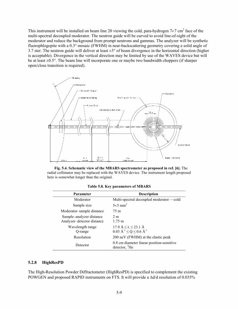
The Mica Backscattering Spectrometer (MBARS) is a mica-based crystal analyzer spectrometer operating in near-backscattering conditions achieving an energy resolution of ≈ 200 neV full width at half maximum (FWHM) operating at an elastic neutron wavelength of 20 Å. This instrument will provide unparalleled energy resolution coupled with a very broad dynamic range in energy transfer of ±50 µeV (±200 resolution widths). MBARS requires sharp neutron pulses at a low-repetition rate; therefore, it is ideally matched to a high timing resolution (de-coupled) cold moderator at STS. This concept is nearly identical to an early proposal [6] (Figure 5.4) but proposes an innovative means to filter out high-order contamination from the analyzer crystals using a novel device, the Wide-Angle Velocity Selector (WAVES), under development at ORNL.[7]
5-9
This instrument will be installed on beam line 20 viewing the cold, para-hydrogen 7×7 cm2 face of the multi-spectral decoupled moderator. The neutron guide will be curved to avoid line-of-sight of the moderator and reduce the background from prompt neutrons and gammas. The analyzer will be synthetic fluorophlogopite with a 0.3° mosaic (FWHM) in near-backscattering geometry covering a solid angle of 3.7 ster. The neutron guide will deliver at least ±3° of beam divergence in the horizontal direction (higher is acceptable). Divergence in the vertical direction may be limited by use of the WAVES device but will be at least ±0.5°. The beam line will incorporate one or maybe two bandwidth choppers (if sharper open/close transition is required).
Fig. 5.4. Schematic view of the MBARS spectrometer as proposed in ref. [6]. The
radial collimator may be replaced with the WAVES device. The instrument length proposed here is somewhat longer than the original.
Table 5.8. Key parameters of MBARS
Parameter Description Moderator Multi-spectral decoupled moderator —cold
Sample size 5×5 mm2 Moderator–sample distance 75 m Sample–analyzer distance
Analyzer–detector distance 2 m 1.75 m
Wavelength range Q-range
17.9 Å ≤ λ ≤ 23.1 Å 0.03 Å-1 ≤ Q ≤ 0.6 Å-1
Resolution 200 neV (FWHM) at the elastic peak
Detector 0.8 cm diameter linear position-sensitive detector, 3He
5.2.8 HighResPD
The High-Resolution Powder Diffractometer (HighResPD) is specified to complement the existing POWGEN and proposed RAPID instruments on FTS. It will provide a ∆d/d resolution of 0.035%

5-10
matching the world’s highest-resolution neutron diffraction instruments at JPARC and ISIS. This instrument will be the longest instrument at the SNS site and will require the low repetition rate of the STS to give it a sufficiently broad wavelength band to cover a broad range of d-spacings.
This instrument will be located on beam line 21 viewing the cold, para-hydrogen 7×7 cm2 face of the multi-spectral decoupled moderator. This beam line views the moderator at normal incidence, and the site geography allows the instrument to be as long as 120 m. Both of these elements are required to achieve the high-wavelength resolution required by this instrument. The moderator is anticipated to provide a moderator pulse width of 6.8 µsec at a neutron wavelength of 1 Å, giving ∆λ/λ of 2.2•10-4 at 120 m, which is sufficient to achieve the desired resolution. The beam line will be straight to provide uniform illumination across the width of the sample. Optimization might result in a slightly shorter instrument at 100 m, providing a bit more bandwidth in a single frame, 4 Å vs 3.3 Å, to cover a broader range in d-spacing at a correspondingly reduced wavelength resolution of ∆λ/λ =2.6•10-4. One or possibly two bandwidth choppers will define the incident neutron wavelength band and a T0 chopper will be required. The instrument must preserve the ability to operate effectively at 5 Hz when the broadest wavelength band in a single frame is required.
Table 5.9. Key parameters of HiRes-PD.
Parameter Description Moderator multi-spectral decoupled moderator—cold
Sample size 0.5 to 1.0 cm diameter; 1 to 2.5 cm tall Moderator–sample
distance 120 m
Sample–detector distance
Backscattering and 90°: 2 m Low angle: 3 m
Wavelength range 0.5 Å ≤ λ ≤ 8 Å Resolution ∆d/d = 0.035%
Detector Low-angle: 0.8 cm diameter linear position-sensitive detector, 3He Backscattering and 90°: TBD
5.3 COMMON COMPONENTS
The neutron scattering instruments have many components in common. Common designs and standardization of requirements will result in lower cost and efficiency.
5.3.1 In-monolith Neutron Optics
The smaller, high-brightness STS moderators will enable better optimization of neutron optics systems, but probably at the cost of increased mechanical complexity and possibly active alignment systems. Particularly in the near moderator regions, care must be taken in the mechanical design of the target monolith to support the higher precision required. It will be important to support a close approach to the moderator of neutron optical systems, ≈60 cm or less, to minimize the effects of under-illumination of the neutron optics system. Instrument Systems will provide the designs and internal components and will be responsible for installation of the eight beam line inserts that support the baseline instrument suite. As noted in Section 4.5.4, Target Systems will provide the remaining 14 “blank” inserts required to close the empty beam line ports.

5-11
5.3.2 Neutron Choppers
Neutron choppers are rotating mechanical devices that interrupt the neutron beam to modify the wavelength and/or time distribution of neutrons in the incident (and possibly in the scattered) neutron flight path. The three general types of neutron choppers used on the SNS FTS will certainly find application at STS beam lines, with the possible exception of the high-speed Fermi choppers (vertical rotation axis) used on the Cold Neutron Chopper Spectrometer for pulse-shaping and on the Wide Angular-Range Chopper Spectrometer (ARCS), the Fine-Resolution Fermi Chopper Spectrometer (SEQUOIA), and the Hybrid Spectrometer (HYSPEC) for monochromatization. As instrument concepts mature, the lower repetition rate of STS relative to FTS may require modifications to both the bandwidth and the T0 choppers.
Bandwidth choppers
Bandwidth choppers are devices that rotate aluminum or carbon fiber disks coated with neutron adsorbing material. One or more apertures are cut out of the disk, which is phased with the neutron source to allow neutrons within defined wavelength ranges to be transmitted while the remainder are removed. At the STS 10 Hz repetition rate, fewer bandwidth choppers will be required than is typical at FTS, to prohibit long-wavelength neutrons originating from a previous frame to transmit through a subsequent open state of the chopper (see the timing diagram in Figure 5.5). The low repetition rate also reduces the need to place a chopper close to the face of the target monolith. For many instruments, a single bandwidth chopper might be sufficient. In some cases, a sharper transition between the open and closed states may be desired, requiring a larger disk than in use at FTS. These types of choppers are already being developed by vendors for the European Spallation Source and should be readily available for STS instruments. Every neutron scattering beam line is anticipated to require at least one or perhaps two bandwidth choppers.
Fig. 5.5. Timing diagram showing contamination at λ = 38.6 Å for a single bandwidth
chopper located at 10 m from the moderator. At these detector and chopper distances, contamination occurs in the third and fourth frame at 38.6 Å ≤ λ ≤ 53.5 Å. Placing the chopper closer to the moderator and target monolith shifts the contamination band to longer wavelengths.

5-12
T0 choppers
Each short beam line, of which there are likely to be several, will require a bender (a multi-channel curved guide), a T0 chopper, or perhaps both to minimize the gamma rays and high-energy neutrons produced as the proton beam strikes the neutron production target. This chopper rotates a block of Inconel through the beam path at the instant protons reach the target, and it is large enough to continue to block the beam for some short period thereafter; but it must move out of the beam fast enough to allow the minimum desired neutron wavelength to pass by unimpeded. For the canonical case of 10 Hz operation—a disk radius of 25 cm, 8 m from moderator to chopper, and a 5 cm neutron beam width—the chopper requires 0.0032 s to move from a fully closed to a fully open state, which at this distance corresponds to a wavelength band of 1.6 Å. This is unlikely to be acceptable for most beam lines requiring a T0 chopper. Either the chopper will have to operate at a higher harmonic of the source frequency, which will have the undesirable effect of blocking the beam for one or more periods in the middle of the frame, or a new T0 chopper will need to be designed with a larger radius and hence a larger footprint adjacent to the beam line.
Fast Disk Choppers
Fast disk choppers rapidly rotate neutron absorbing disks, often two counter-rotating disks used in tandem, through the neutron beam to produce a degree of monochromatization or pulse shaping. Open times of as little as 10 µsec are desired. These choppers will be very similar to those used on FTS but may require more flexibility in the distance between disks and in the aperture design. Instruments that need to use repetition rate multiplication will require more choppers of this type than their counterparts at FTS.
5.3.3 Neutron Guides/Optical Components
The average anticipated length of an STS neutron scattering instrument is ≈45 m (see Table 5.1) which is considerably longer than the average FTS length of 28 m. This additional length puts a premium on standardizing both the mechanical housing and the alignment systems deployed. Novel neutron optics systems delivering highly optimized beams (in size, divergence, and polarization) will likely require much better alignment systems and stability than the guides currently used at FTS. In some cases, active or at least periodic adjustment and alignment may be required.
5.3.4 Detectors
Instruments at the SNS currently use one of four detector technologies (see Fig. 5.6): (1) linear position sensitive 3He tube (LPSD), (2) multi-wire 3He gas chamber, (3) lithium-glass scintillator-based Anger camera, or (4) LiF/ZnS wavelength-shifting fiber detector. Several of these technologies will be used in STS neutron scattering instruments. Table 5.10 summarizes the key operating parameters of this current generation of detectors. The higher peak brightness (as great as 17× relative to the coupled moderators on a 2 MW FTS at a neutron wavelength of 2 Å) will challenge or exceed the limits of current SNS detector and electronics technologies. Table 5.11 provides an estimate of the detector requirements for the eight instruments described above. If Anger camera technology is deployed as indicated in the table, development will be required in two areas: HiRes-SWANS requires a vacuum-compatible low-angle detector; and DyPOL and QIKR require a detector that is insensitive to stray magnetic fields, which would likely require replacing the current photomultiplier tubes with solid state technology. The global shortage of 3He has driven a large international effort to develop alternate technologies, some of which may provide viable and desirable alternatives to the detectors listed in Table 5.11. The maturity of these technologies and their cost, capabilities, and maintainability will all be considered in final detector choices. ORNL is the custodian of sufficient 3He to meet the needs described in Table 5.11.

5-13
Fig. 5.6. Neutron detector types currently in use at the SNS first target station. Panels (a) and (b)
show 3He tubes; (c) is a multi-wire 3He gas detector; (d) is a lithium glass–based Anger camera; (e) is an LiF/ZnS wavelength-shifting fiber detector.
Table 5.10. Operating parameters for detectors currently used at SNS first target station
Technology Resolution Efficiency at 2 Å
Local rate counts/cm2/s
Full detector rate counts/s
Gammaa
sensitivity Magnetic field
sensitivity LPSD 5–25 mm 80–90% 10–20K 100K 10-7–10-8 None
Multi-wire 1.5–2 mm 70% 20K 20K 10-7–10-8 None Anger
Camera 1.2 mm 80–90% 40K 40K 10-5–10-6 Requires < 25 G
Wavelength shifting
fiber 5 mm × 5 cm 50% 10K 10K 10-6–10-8 Requires
< 100 G
a Gamma sensitivity is defined as the fraction of boron energy gammas reported as counts by the detector system.
(a)
(b)
(c)
(d)
(e)

5-14
Table 5.11. Estimate of the detector requirements for the eight initial instruments
Instrument Requirements (resolution, average count rate) Coverage Possible detector
technology Notes
Zeemans 1 cm, TBD ≈10 m2 8 mm 3He LPSD High stray magnetic fields
QIKR 1 mm, 0.5–1M 20 × 20 cm2 3He 2D if possible
Anger camera (alternate)
Possible polarized beam
HiRes-SWANS Low-mid angle: 8 mm, 500K Small angle: 1–2 mm, 500K
≈2 m2 20 × 20 cm2
8 mm 3He LPSD Anger camera
Curved detector possible
VERDI 1 cm, 100K 17 m2 8 mm 3He LPSD DyPOL 0.5–1 mm, 100K 1.3–1.7 m2 Anger camera
CHESS 1.5 cm, 20–40K 50 m2 1.5 cm 3He LPSD >100 kcounts/sec peak rate
MBARS 1 cm, 20K 0.2 m2 1 cm 3He LPSD
HighResPD ≈1–3mm, 50K TBD TBD, 3He at low angles
May require new geometry for
backscattering
5.3.5 Data Acquisition and Instrument Controls
Data acquisition and instrument controls will build on systems and standards developed for FTS to facilitate common operational support for the instruments across both facilities. These systems are in a state of transition for FTS instruments as new methods, algorithms, and frameworks are deployed; these include Accelerating Data Acquisition Reduction and Analysis (ADARA), which provides near-real-time access to reduced data sets during an experiment and handles data transfer and management. Instrument control is transitioning to an Experimental Physics and Industrial Control System (EPICS) –based framework. Instrument Systems will provide the necessary hardware and programming support to deploy these systems on the eight project instruments.
5.3.6 Sample Environment
The neutron scattering instruments require a suite of equipment to control the environment around samples. Sample environments typically include control of temperature, pressure, magnetic field, or some combination thereof, as well as more specialized environments that may be customized to particular instruments. Some of this equipment can be used across multiple instruments, but much will be customized to the particular geometries of individual instruments. This is especially true for Zeemans, which will require the development of customized sample environment equipment that is compatible with both the high-magnetic-field environment and atypical instrument geometry. Table 5.12 lists some of the sample environment types and requirements needed by the eight instruments described. Instrument systems will provide the sample environment equipment required to commission the experiment and deliver its initial science program.

5-15
Table 5.12. List of sample environment equipment for the eight project instruments.
Instrument Equipment description Notes
Zeemans Temperature control from 50 mK to 1000°C All sample environment equipment will be unique to Zeemans
QIKR • Langmuir trough • Pressure cell • Humidity cell
Range of equipment—probably compatible with FTS Liquids Reflectometer suite
HiRes-SWANS • Automatic sample changer: −2–80° C • Furnace with auto-changer: 30–500° C
May require additional customized apparatus for grazing incidence geometry
VERDI
• 12 T superconducting cryomagnet • Cryostat with mK inserts • Closed-cycle refrigerator with automatic
sample changer
DyPOL • Cryostream : T < 100K • Integrated dynamic nuclear polarization
device
CHESS
• Low temperature: T ≤30 mK • 12 T superconducting cryomagnet • Furnace : 800°C • Integrated device to measure S • Closed-cycle refrigerator with automatic
sample changer • Pressure cells
May require custom apparatus to take full advantage of nearly 2π detector solid angle
MBARS • Closed-cycle refrigerator: 5–800 K • Furnace: 30–1600°C • Cryostat: 1.5–300 K
HighResPD
• Closed-cycle refrigerator with automatic sample changer
• Furnace: 1100°C • Cryo-furnace: 5–700 K • Cryostat: 2–300 K
5.4 INTERFACES
Instrument Systems relies on a number of the other work packages for certain areas of support and has a number of interfaces across the project as delineated:
• Conventional Facilities: Instrument Systems relies on Conventional Facilities to provide the buildings that house the instrument end stations and transport lines, as well as to provide standard utilities routed to designated locations inside the buildings. As instrument designs mature, requirements for floor loading and stability will be developed. Routing utilities from these locations to the instrument end stations as required will be the responsibility of Instrument Systems.
• Target Systems: Instrument Systems interfaces with Target Systems both within and external to the target monolith. Final selection of both the types and geometries of neutron moderators must support the instrument requirements. Instrument Systems will provide the beam line inserts that house neutron optics and neutron beam extraction equipment for the eight project instruments. STS will have “beam

5-16
line access pits” outside the target monolith that provide a common shielded bunker, which will house instrument components from the edge of the target monolith to an approximately 11 m radius. Instrument Systems will install choppers, neutron optical components, and local instrument shielding in the interior of this area.
• Integrated Controls: Instrument Systems relies on Integrated Controls for distribution of the Ethernet communications network for the instrument hardware and data acquisition systems, and the appropriate timing signals required to synchronize them to accelerator proton pulse production. These systems are anticipated to be similar to those currently in use for instruments at FTS.
5.5 DEVELOPMENT
Development efforts specific to individual beam lines, such as the unique sample environment equipment associated with Zeemans, are described under each specific instrument. This section outlines anticipated development that is common to multiple beam lines.
5.5.1 Neutron Choppers
The modifications possibly required for bandwidth choppers (larger disks) and high-speed, fast choppers (disk size, aperture arrangement, and distance between disks) are also required by European Spallation Source instruments. It is anticipated that chopper vendors will be able to provide these choppers without further development effort under the STS project. However, it is important that specifications be iterated with these vendors in a timely fashion.
Changes to the T0 chopper require development, primarily in the form of new engineering designs, tuning of control parameters, and testing, will be the responsibility of the STS project.
5.5.2 Neutron Detectors
Selection of the final instrument suite may require a different set of detector requirements from those described earlier. Following are some known and expected areas in which detector development will be required.
• Current and proposed reflectometers are underserved by the current 2-dimensional, multi-wire 3He gas detectors; and, although it is desirable, existing gas detector technology may not meet the needs for speed and resolution. These instruments could be served by a scintillating detector that is insensitive to magnetic fields or possibly by an ionization mode or resistive plate detector. Faster electronic encoding of neutron position is likely to be a key requirement to keep up with the high peak count rate of QIKR.
• Improving the spatial resolution of the current Anger camera from 1.2 to 0.5 mm would benefit DyPOL in its ability to study very small samples on the order of 0.03 mm3 or smaller. Progress in this area requires a brighter scintillator than the GS20 lithium glass currently used.
• There will be a strong preference for 3He detectors for a number of the instruments, particularly for the large-detector-area inelastic instruments like CHESS. Improvements are needed in the methods for linking these large systems together, including addressing methods of powering and communicating with these units.
• It may be impractical to provide sufficiently high spatial resolution for the backscattering and 90° detectors of HighResPD using 3He detector technology. In particular, the backscattering detector

5-17
would be best served by a segmented, annular detector geometry that follows the Debye-Scherrer rings.
• The higher peak and sustained count rates on many of the STS instruments will require development in support of higher-speed communications and streaming of the data from the detector through the data acquisition system and associated processing and into high-speed data storage.
5.6 REFERENCES
1. Instruments for Emerging Science: A Science Case for the Second Target Station (2014). A. T. Savici and G. E. Granroth, SNS-NSSD-TOF-TR-0002-R00, Oak Ridge National Laboratory, 2009.
2. G. E. Granroth, A. T. Savici, M. D. Bird, L. Santodonato, Y. Lee, and C. L. Broholm, “Zeemans: A high magnetic field beamline for the SNS, ICANS XIX,” 19th meeting on Collaboration of Advanced Neutron Sources, Grindewald, Switzerland , March 18–22, 2010.
3. A. T. Savici et al., “Zeemans—A new facility to probe matter at high magnetic field through neutron scattering,” J. Phys.: Conf. Ser. 251, 0120573 (2010).
4. J. Voigt et al., “Chopper layout for spectrometers at long pulse neutron sources,” Nucl. Instrum. Meth. A 741, 26–32 (2014).
5. H. N. Bordallo, K. W. Herwig, and G. Zsigmond, “Analytical calculations and Monte-Carlo simulations of a high-resolution backscattering spectrometer for the long wavelength target station at the Spallation Neutron Source,” Nucl. Instrum. Meth. A 491, 216–225 (2002).
6. E. Mamontov, “Wide-angle mechanical velocity selection for scattered neutrons in inelastic neutron spectrometers,” Nucl. Instrum. Meth. A, 759, 83–91 (2014).