Embed Size (px)
Citation preview

SCHEDULE-VII
TECHNICAL SPECIFICATIONS
Specification No. 01410116
11KV/415V, 400 kVA, 630 kVA, 1000 kVA and 1600 kVA,
SINGLE RATIO, ONAN TYPE DISTRIBUTION TRANSFORMERS


Notice for revision of specification (summary sheet)
Attention of tenderers for the tender to be invited with following additions/ amendments made in specification
Sr.No. Existing specification no. Revised specification no. Date of revision
1 01410114 01410116 05/10/16
Sr.No.
Existing section/
clause No.
Description of existing clause
Revised Section/
Clause No.
Description of additions/amendments
1 Section 4 Clause
4.2 Description
Section 4 Clause 4.2
Rating of 995 KVA transformer is changed to 1000 KVA, as per clause 7.1 of IS:1180(Part-I)/2014
2 Section 5 Clause
5.1 BIS Standard Mark Certificate
and Type tests report Section 5 Clause 5.1
BIS Standard Mark Certificate and Type tests report from BIS standard lab shall be submitted by tenderer alongwith the offer
3 Section no- 5
clause no. 5.1.1.e
Rated Power Section no- 5
clause no. 5.1.1.e
Rated power of 995 KVA transformer is changed to 1000 KVA, as per clause 7.1 of IS:1180(Part-I)/2014
4 Section no- 5
clause no. 5.1.1.J Insulation level
Section no- 5 clause no.
5.1.1.J
Description revised by adding reference of IS:1180(Part-I)/2014 as per clause 7.4
5 Section no- 5
clause no. 5.1.1.m
BIS Standard Mark Section no- 5
clause no. 5.1.1.m
Each transformer shall be marked with standard mark and Energy Efficiency Level
6 Section no- 5
clause no. 5.1..2 Fittings
Section no- 5 clause no.
5.1..2
Fittings shall be as per clause 20 of IS-1180 ( Part-I)/2014
7 Section no- 5 clause no. 5.2
Rating Plate Section no- 5 clause no. 5.2
Description i.e. Rating plate details revised as per clause 13.1 of IS:1180(Part-I)/2014.
8 Section no- 5
clause no. 5.3 & 5.4
Terminal marking plate Section 5
Clause No.5.3 & 5.4
Description i.e. Terminal marking plate details revised as per clause 13.2 of IS:1180(Part-I)/2014. Earthing lugs shall be of copper of size 120 sq.mm..
9 Section no- 5
clause no. 5.5.3 Jacking Pad
Section no- 5 clause no.
5.5.3
Description i.e. Jacking arrangement shall be provided to all items so as to facilitate easy lifting by means of jack.
10 Section no- 5 clause no. 5.8
Oil level Indicator Section no- 5 clause no. 5.8
Additional description is added as per clause 20.1.b of IS:1180
11 Section no- 5 clause no. 5.9
Thermometer Pocket Section 5 Clause 5.9
Description revised by mentioning with cap only as per clause 20.1.g of IS:1180
12 Section no- 5
clause no. 5.11,5.12
Conservator Section 5
Clause 5.11,5.12
Additional description is added as per clause 16.2 and 16.3 of IS:1180
13 Section no- 5
clause no. 5.15.9 Transformer cable boxes
Section no- 5 clause no.
5.15.9
Rating of 995 KVA transformer is changed to 1000 KVA.
Sr.No.
Existing section/
clause No.
Description of existing clause
Revised Section/
Clause No.
Description of additions/amendments
14 Section no- 5
clause no. 5.21.c Special requirements
Section no- 5 clause no.
5.21.c
As per clause 7.10.2 of IS:1180 , the permissible temperature rise of winding and oil is revised.
15 Section no- 5
clause no. 5.21.d Special requirements
Section no- 5 clause no.
5.21.d
As per clause 7.8 of IS:1180 , limits of losses are revised.
16 Section no- 5
clause no. 5.21.k Special requirements
Section no- 5 clause no.
5.21.n
As per clause 15.5 of IS:1180 , Description revised by mentioning details of painting for inside and outside of the tank.
17 Section no- 5
clause no. 5.22.b Miscellaneous Requirement
Section no- 5 clause no.
5.22.b
As per clause 10.1.5 of IS-1180(Part-I)2014, The LV Bushing with copper stem shall be of the rating 1KV.
18 Section no- 5
clause no. 5.24.2 Maximum temperature rise at
rated kVA
Section no- 5 clause no.
5.24.2
As per clause 7.10.2 of IS:1180 , the permissible temperature rise of winding and oil is revised.
19 Section no- 5
clause no. 5.24.4 Maximum full load losses
Section no- 5 clause no.
5.24.5 Description is added i.e. at 100%
20 Section no- 5
clause no. 5.24.9 Transport dimensions
Section no- 5 clause no.
5.24.9
Rating of 995 KVA transformer is changed to 1000 KVA.
21 Section no- 6
clause no. 6.1.1 Tests
Section no- 6 clause no.
6.1.1
Reference of IS:1180 clause 21.2, is added.
22 Section no- 6
clause no. 6.1.1.1
Routine tests
Section no- 6 clause no.
6.1.1.1
Routine tests are modified as per IS:1180 (part-I) 2014 clause 21.2. Pressure tests and Oil leakage tests are added.
23 Section no- 6
clause no. 6.1.1.5
Type test. Section no- 6
clause no. 6.1.1.5
Type tests are modified as per IS:1180 ( part-I) 2014 clause 21.3.

BRIHAN-MUMBAI ELECTRIC SUPPLY & TRANSPORT UNDERTAKING
(OF THE BRIHAN MUMBAI MAHANAGARPALIKA)
Specification No.- 01410116
SECTION-1: GENERAL
1.1 Tender Document
1.1.1 This tender document shall be read and understood as a whole inclusive of all
Annexures, Drawings etc. and every section or sub-section of this document shall be
incorporated in proper context with other sections contained herein. 1.1.2 This specification covers the manufacturer, testing before dispatch and supply of
11KV/415V, single ratio, ONAN type distribution transformer. 1.1.3 All work covered by this specification shall be carried out in accordance with the
‘General Conditions of Contract’. 1.1.4 Wherever the directions to the tenderers embodied herein conflict with those specified
in the General Conditions of Contract, the former shall be binding in preference to the latter.
1.2 Standards 1.2.1 Except as specified herein, all equipment shall comply with the requirements of the
latest relevant Indian Standard Specifications (as amended to-date). 1.2.2 Where Indian Standard Specification does not exist, the relevant BS or IEC Standard
Specification shall be taken as standard.
1.2.3 If the equipment offered is manufactured according to some other standard, it shall be
clearly stated and a copy of the latest publication of the standard in English shall be
submitted with the offer. 1.3 Legislation
1.3.1 The whole of the equipment shall comply in every respect with the provisions of
relevant Government Legislations and/or Rules and Regulations governing manufacture,
installation, operation and maintenance of the equipment.
1.3.2 Tenderers shall ensure that all safety measures are provided in the equipment against
hazards to life and property and that the proper installation and use of the equipment shall not contravene any enactments, rules and by-laws of the Government and the Local Authority.
1.4 Departure from Specification 1.4.1 If due to any reason tenderers find it necessary to depart from the provisions of any
section of the specification such departures shall be clearly stated and underlined giving full reasons.
1.4.2 If the departures from the provisions of any section of this specification are not notified in writing it will be presumed that tenderers will abide by this specification.
1.4.3 Any suggestion, comment or advise to include in this document additional provisions in
respect of any special device or attachment/necessary but not already specified herein, may be put forward by the tenderers giving full details of the special/additional features of the equipment together with the justification for its inclusion.
1.5 Technical Data
1.5.1 Tenderers shall give full specifications of the equipment/materials offered and shall
supply technical literature and descriptive particulars together with drawing and illustrations to indicate the type and design of the equipment/material offered.
1.5.2 Tenderers shall supply such technical data, characteristics and statistical information as required to study the comparative merits and performance of different types and design of the equipments/materials.
1.6 Materials and Workmanship
1.6.1 The equipment/materials shall conform to the best engineering practice in design, materials and construction so as to ensure reliability, economy and safe and convenient operation.
1.6.2 Tenderers shall supply all incidental items necessary or usual for such equipment for
efficient working and for erection/installation purpose.
1.6.3 Manufacturers shall give details of the experience in the supply of similar equipment.
A list of important customers who have been supplied with similar equipment with
details of order executed shall be furnished. Details shall include rating of the equipment, quantity, purchase order reference etc.
1.6.4 Guarantee
All the transformers supplied against this Specification shall be guaranteed for a period
of 60 months from the date of installation but not later than 66 months from the date of acceptance for satisfactory operation of transformer. However any engineering error, omission ,wrong provisions, etc. which do not have any effect on the time
period, shall be attended/rectified by tenderer as and when observed/pointed out without any price implication to the entire satisfaction of the Undertaking.
1.6.5 The successful tenderer shall make goods at his own expense all necessary alterations replacement to prevent any recurrence of such defects on all the equipment/materials supplied by him.
1.6.6 All corresponding similar materials and removable parts shall be made to gauge and
shall be interchangeable with each other.
1.6.7 The equipment/materials may be rejected at discretion of the General Manager if the
test results are not satisfactory and the permissible tolerances are exceeded.
1.7 Instructions for Erection/Installation
Tenderers shall furnish the necessary instruction manual for erection/installation of the equipment/materials and shall also state precautions/provisions if any to be made for proper use afterwards.
SECTION-2: DESCRIPTION OF THE POWER SYSTEM 2.1 Grid
2.1.1 The Tata Power Company Ltd. (TPCL) and the Maharashtra State Electricity Board have their generating stations located in different parts of Maharashtra State and form an interconnected transmission system in the Mumbai-Pune Region.
2.1.2 Power from this system is transmitted at 220 / 110kV through overhead conductors and
underground cables amongst others to TPCL’s five main receiving stations at Backbay,
Carnac, Parel, Dharavi and Mahalaxmi situated in the island of Mumbai, where they have installed either delta/star or star/zigzag step down transformers with star point effectively earthed for making power available to their consumers at 110 / 33 / 22kV.
2.2 Existing B.E.S.T. System
2.2.1 The B.E.S. & T. Undertaking on behalf of Brihan Mumbai Mahanagarpalika (who are the
licensees for the distribution of electric power within the City limits of Mumbai) receives power in bulk from the Tata Power Company Ltd. at 110 / 33 / 22kV, 3 Phase, 50 Hz.
2.2.2 Bulk power at 110 / 33 / 22kV is transmitted from TPCL’s five main receiving stations through effectively earthed underground cables to B.E.S.T.’s receiving substations situated at different localities in Mumbai where the B.E.S. & T. Undertaking has installed
110 / 33kV, 110 / 11kV, 33 / 11kV or 22 / 11kV, Star-z, star/star, delta/star power transformers of Vector group YNzn11, Ynyn0, 31 Dyn1 with neutral earthed with/without a resistance. Where the transformation is 110 / 11kV or 110 / 33kV, 22
/ 11kV or 33 / 11kV, the star point of the transformers has been effectively earthed. The power transformers are provided with OLTC gear to regulate and maintain the 11kV voltage fairly constant.
2.2.3 Underground 11kV (effectively earthed) feeder cables radiate from the B.E.S.T.
receiving substations to supply power to a large number of distribution substations and
to certain consumer’s substations. These feeders form a radial network under which each feeder supplies on an average 4 to 5 substations in series.
2.2.4 Power at 11kV is stepped down to 415/240V at the distribution substations where the various sizes of 11kV/415-240Volt delta/star transformers of vector group 41 Dyn11 are installed. The star point of these transformer is solidly earthed and is also brought
out to an insulated terminal for the 3 phase, 4 wire distribution system. 2.2.5 The 415/240V secondary distribution system comprises of a vast network of
underground four core cables, suitably sectionalised by means of distribution pillars, to which service lines are teed off to supply power to medium and low voltage consumers.
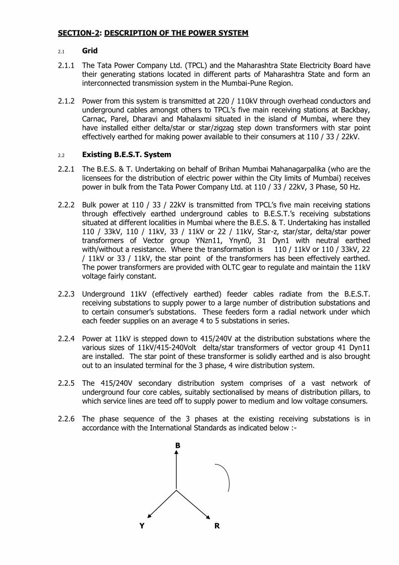
2.2.6 The phase sequence of the 3 phases at the existing receiving substations is in
accordance with the International Standards as indicated below :-
B
Y R
SECTION-3: PREVAILING SERVICE CONDITIONS
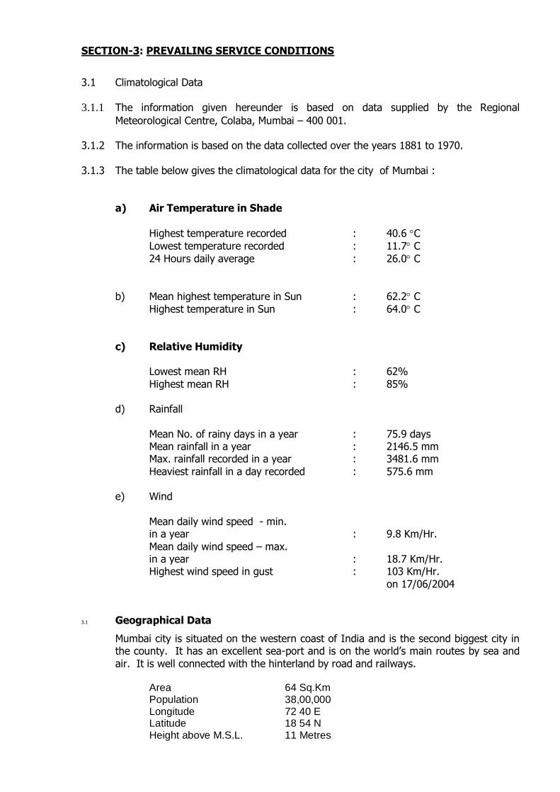
3.1 Climatological Data
3.1.1 The information given hereunder is based on data supplied by the Regional
Meteorological Centre, Colaba, Mumbai – 400 001. 3.1.2 The information is based on the data collected over the years 1881 to 1970.
3.1.3 The table below gives the climatological data for the city of Mumbai :
a) Air Temperature in Shade
Highest temperature recorded : 40.6 C
Lowest temperature recorded : 11.7 C
24 Hours daily average : 26.0 C
b) Mean highest temperature in Sun : 62.2 C
Highest temperature in Sun : 64.0 C
c) Relative Humidity
Lowest mean RH : 62%
Highest mean RH : 85%
d) Rainfall
Mean No. of rainy days in a year : 75.9 days Mean rainfall in a year : 2146.5 mm Max. rainfall recorded in a year : 3481.6 mm
Heaviest rainfall in a day recorded : 575.6 mm
e) Wind
Mean daily wind speed - min. in a year : 9.8 Km/Hr.
Mean daily wind speed – max. in a year : 18.7 Km/Hr. Highest wind speed in gust : 103 Km/Hr.
on 17/06/2004
3.1 Geographical Data
Mumbai city is situated on the western coast of India and is the second biggest city in the county. It has an excellent sea-port and is on the world’s main routes by sea and
air. It is well connected with the hinterland by road and railways. Area 64 Sq.Km Population 38,00,000 Longitude 72 40 E Latitude 18 54 N Height above M.S.L. 11 Metres
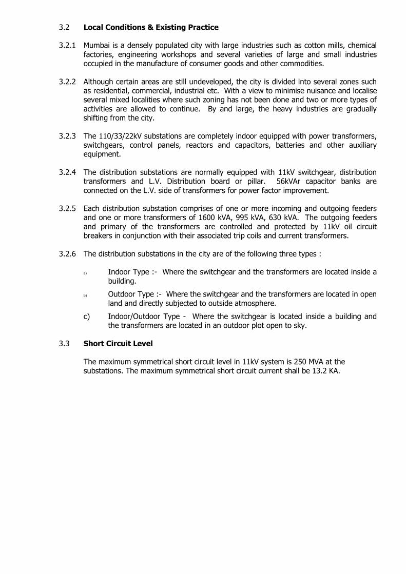
3.2 Local Conditions & Existing Practice 3.2.1 Mumbai is a densely populated city with large industries such as cotton mills, chemical
factories, engineering workshops and several varieties of large and small industries occupied in the manufacture of consumer goods and other commodities.
3.2.2 Although certain areas are still undeveloped, the city is divided into several zones such as residential, commercial, industrial etc. With a view to minimise nuisance and localise several mixed localities where such zoning has not been done and two or more types of
activities are allowed to continue. By and large, the heavy industries are gradually shifting from the city.
3.2.3 The 110/33/22kV substations are completely indoor equipped with power transformers, switchgears, control panels, reactors and capacitors, batteries and other auxiliary equipment.
3.2.4 The distribution substations are normally equipped with 11kV switchgear, distribution
transformers and L.V. Distribution board or pillar. 56kVAr capacitor banks are
connected on the L.V. side of transformers for power factor improvement. 3.2.5 Each distribution substation comprises of one or more incoming and outgoing feeders
and one or more transformers of 1600 kVA, 995 kVA, 630 kVA. The outgoing feeders
and primary of the transformers are controlled and protected by 11kV oil circuit breakers in conjunction with their associated trip coils and current transformers.
3.2.6 The distribution substations in the city are of the following three types :
a) Indoor Type :- Where the switchgear and the transformers are located inside a
building.
b) Outdoor Type :- Where the switchgear and the transformers are located in open
land and directly subjected to outside atmosphere.
c) Indoor/Outdoor Type - Where the switchgear is located inside a building and the transformers are located in an outdoor plot open to sky.
3.3 Short Circuit Level
The maximum symmetrical short circuit level in 11kV system is 250 MVA at the substations. The maximum symmetrical short circuit current shall be 13.2 KA.
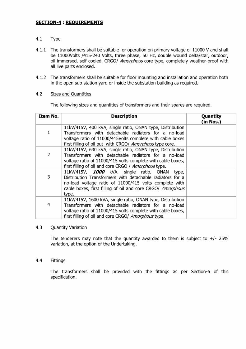
SECTION-4 : REQUIREMENTS
4.1 Type 4.1.1 The transformers shall be suitable for operation on primary voltage of 11000 V and shall
be 11000Volts /415-240 Volts, three phase, 50 Hz, double wound delta/star, outdoor, oil immersed, self cooled, CRGO/ Amorphous core type, completely weather-proof with all live parts enclosed.
4.1.2 The transformers shall be suitable for floor mounting and installation and operation both
in the open sub-station yard or inside the substation building as required.
4.2 Sizes and Quantities The following sizes and quantities of transformers and their spares are required.
Item No. Description Quantity
(in Nos.)
1 11kV/415V, 400 kVA, single ratio, ONAN type, Distribution Transformers with detachable radiators for a no-load
voltage ratio of 11000/415Volts complete with cable boxes first filling of oil but with CRGO/ Amorphous type core.
2 11kV/415V, 630 kVA, single ratio, ONAN type, Distribution
Transformers with detachable radiators for a no-load voltage ratio of 11000/415 volts complete with cable boxes, first filling of oil and core CRGO / Amorphous type.
3 11kV/415V, 1000 kVA, single ratio, ONAN type, Distribution Transformers with detachable radiators for a no-load voltage ratio of 11000/415 volts complete with
cable boxes, first filling of oil and core CRGO/ Amorphous type.
4 11kV/415V, 1600 kVA, single ratio, ONAN type, Distribution
Transformers with detachable radiators for a no-load voltage ratio of 11000/415 volts complete with cable boxes, first filling of oil and core CRGO/ Amorphous type.
4.3 Quantity Variation
The tenderers may note that the quantity awarded to them is subject to +/- 25% variation, at the option of the Undertaking.
4.4 Fittings
The transformers shall be provided with the fittings as per Section-5 of this specification.
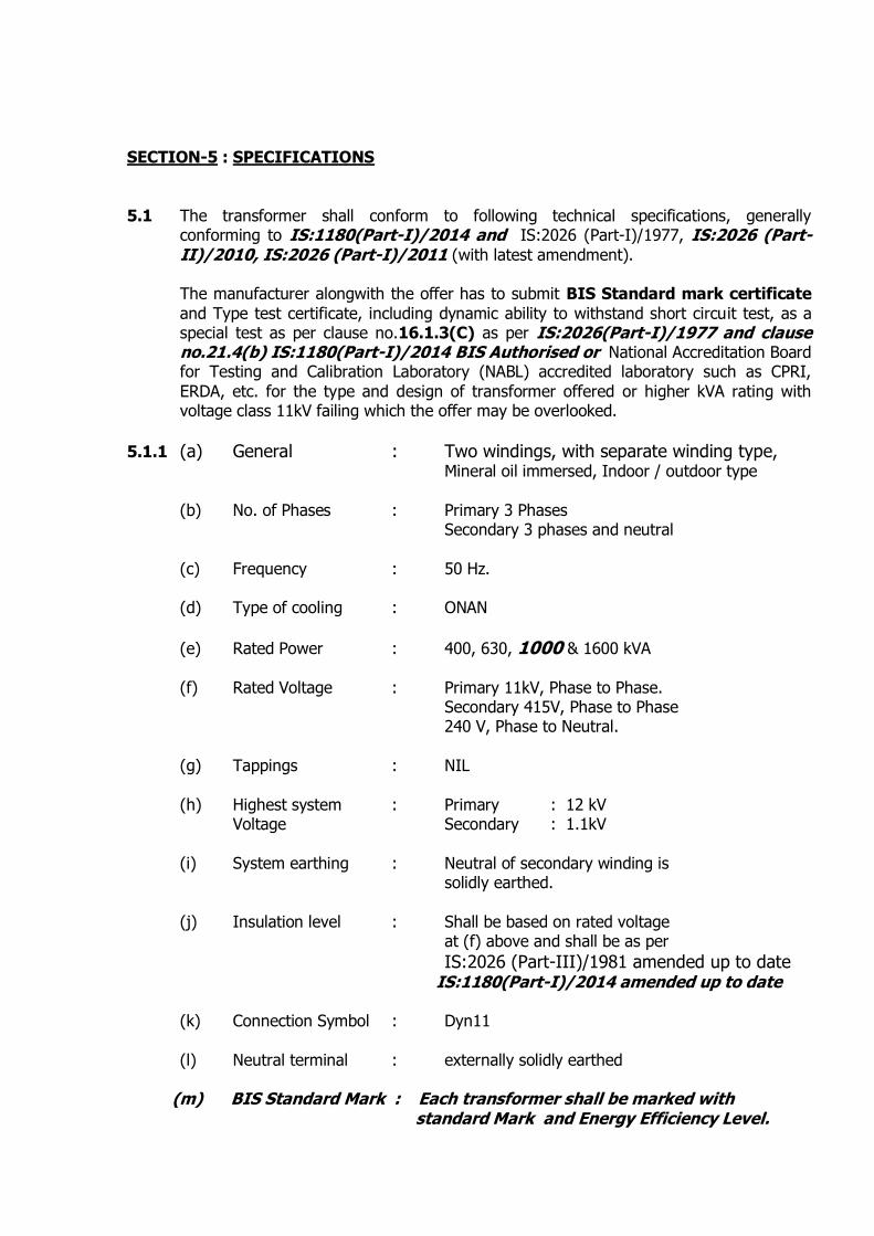
SECTION-5 : SPECIFICATIONS
5.1 The transformer shall conform to following technical specifications, generally
conforming to IS:1180(Part-I)/2014 and IS:2026 (Part-I)/1977, IS:2026 (Part-II)/2010, IS:2026 (Part-I)/2011 (with latest amendment).
The manufacturer alongwith the offer has to submit BIS Standard mark certificate
and Type test certificate, including dynamic ability to withstand short circuit test, as a special test as per clause no.16.1.3(C) as per IS:2026(Part-I)/1977 and clause no.21.4(b) IS:1180(Part-I)/2014 BIS Authorised or National Accreditation Board for Testing and Calibration Laboratory (NABL) accredited laboratory such as CPRI,
ERDA, etc. for the type and design of transformer offered or higher kVA rating with voltage class 11kV failing which the offer may be overlooked.
5.1.1 (a) General : Two windings, with separate winding type, Mineral oil immersed, Indoor / outdoor type
(b) No. of Phases : Primary 3 Phases Secondary 3 phases and neutral
(c) Frequency : 50 Hz. (d) Type of cooling : ONAN
(e) Rated Power : 400, 630, 1000 & 1600 kVA
(f) Rated Voltage : Primary 11kV, Phase to Phase. Secondary 415V, Phase to Phase 240 V, Phase to Neutral.
(g) Tappings : NIL
(h) Highest system : Primary : 12 kV Voltage Secondary : 1.1kV
(i) System earthing : Neutral of secondary winding is solidly earthed.
(j) Insulation level : Shall be based on rated voltage at (f) above and shall be as per IS:2026 (Part-III)/1981 amended up to date IS:1180(Part-I)/2014 amended up to date (k) Connection Symbol : Dyn11
(l) Neutral terminal : externally solidly earthed (m) BIS Standard Mark : Each transformer shall be marked with standard Mark and Energy Efficiency Level.
5.1.2 Fittings
Fittings shall be provided as per clause 20 of IS:1180(Part-I)/2014 and applicable items as per Appendix-C of IS:2026 (Part-I)/1977 amended to date.
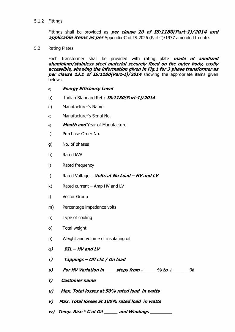
5.2 Rating Plates
Each transformer shall be provided with rating plate made of anodized aluminium/stainless steel material securely fixed on the outer body, easily accessible, showing the information given in Fig.1 for 3 phase transformer as per clause 13.1 of IS:1180(Part-I)/2014 showing the appropriate items given
below :
a) Energy Efficiency Level
b) Indian Standard Ref : IS:1180(Part-I)/2014
c) Manufacturer’s Name
d) Manufacturer’s Serial No.
e) Month and Year of Manufacture
f) Purchase Order No.
g) No. of phases h) Rated kVA
i) Rated frequency
j) Rated Voltage – Volts at No Load – HV and LV k) Rated current – Amp HV and LV
l) Vector Group
m) Percentage impedance volts n) Type of cooling
o) Total weight
p) Weight and volume of insulating oil q) BIL – HV and LV r) Tappings – Off ckt / On load s) For HV Variation in ____steps from -_____% to +______% t) Customer name u) Max. Total losses at 50% rated load in watts v) Max. Total losses at 100% rated load in watts
w) Temp. Rise ° C of Oil _____ and Windings ________
In addition to the above information, the rating plate shall also contain the following :
a) Guaranteed values of No load and full load losses in Watts. b) Guaranteed values of total losses in Watts
c) Overall dimensions in mm.
d) Transport dimensions (with accessories removed) in mm.
5.3 Terminal marking plate :- Engraved on metal plate giving clearly the connection for the
transformer, the terminal markings. Transformer shall be provided with a terminal marking plate in accordance with fig 3 and 4 of IS:1180 clause 13.2., alongwith U,V & W phase abbreviations , if possible provide optional R,Y,& B phase abbrevations.
5.4 Two earthing terminals with crimping type copper lugs of size 120 sq.mm. shall be
provided at the centre of bottom channels supporting the transformer tank with the
earthing symbol ╧. 5.5 Lifting Lugs 5.5.1 The core shall be provided with suitable lifting lugs to enable the complete core and coil
assembly to be lifted out of the tank. 5.5.2 Lifting lugs shall also be provided to the top cover.
5.5.3 The tank shall be provided with lifting lugs located such that there should be no hindrance of other accessories of transformer while lifting the complete tank with core
and coil assembly for loading and unloading. Also jacking arrangement shall be provided to all items so as to facilitate easy lifting by means of jack, though as per clause no. 20.2 of IS:1180(PART –I) 2014, jacking pad is an optional fitting for transformer above 1600KVA.. Please refer drawing no. ES/PL/A-134 Rev. F and ES/PL/A-467 Rev. A.
5.6 Drain valve and Filter valve :
The drain valve and filter valve shall be of brass fabricated type. The drain valve shall be fitted on upper side of transformer tank and shall be connected by M.S. pipe of adequate diameter properly secured at bottom portion of the pipe and shall be brought
at usual level of bottom valve. The pipe shall be from inside the tank. Locking (Anti-theft) arrangement for drain valve is to be provided. The filter valve shall be provided at the top of the tank. The filter valve shall be of same type as that of drain valve. The
drain valve and filter valve shall be provided with embossed name plate stating ‘Bottom drain valve’ and ‘Top filter valve’. Both drain valve and filter valve should be painted in black with an oil paint. Please refer drg. No. ES/PL -92 and ES/PL -92 Rev. ‘A’.

5.7 Dehydrating Breather:
A breather of 500 gms capacity for 400,630 and 1000 kVA and 1 kg for 1600 kVA shall be provided. The breather shall be at a height of 1.5 meters from ground level and the
breather body shall be of totally transparent material to enable easy routine inspection of silica gel. Locking (Anti theft ) arrangement shall be provided for breather as shown in drg. No. ES/PL/A-451 or similar so as to prevent the theft. The breather pipe shall enter the conservator tank from the lower side of the conservator and pass through the oil in the conservator. Please refer drg. No. ES/PL/A-134 Rev. ‘F’. Top cover of
breather must be metallic and not of plastic.
5.8 Oil level indicator with minimum level marked. Oil level gauge indicating oil level at
minimum, 30 ° C and maximum operating temperature as per IS:1180(PART –I) 2014 clause no. 20.1.b.
5.9 Thermometer pocket with cap as per IS:1180(PART –I) 2014 clause no. 20.1.g for measuring oil temperature shall be provided.
5.10 Oil filling hole and plug 5.11 Conservator :
The transformer shall be provided with conservator tank fitted with oil level indicator with minimum level marked. The connecting pipe of the conservator shall be so fitted to transformer tank that the pipe can be detached from the tank. The shut off valve and flange of pipe connecting conservator and main tank is to be provided with locking (Anti-theft) arrangement as shown in Drawing No. ES/PL-92 Rev. ‘A’ or similar. The
conservator shall be supported / fixed on the main body of the transformer tank.
The conservator shall be provided with detachable end plate on one side, preferably on the side which the gauge glass is fitted to enable the maintenance staff to periodically clean the inside of the conservator tank. The oil gauge glass shall be removable and so embodied in the end plate so as to prevent oil leakage. The conservator shall be provided with oil filling hole (dia. 3 inches) with plug. Please refer drawing no. ES/PL/A-134 Rev. ‘F’.
As per IS:1180(PART –I) 2014 clause no. 16.2 & 16.3, the conservator shall be provided with a drain plug and a fitting hole ( 1¼’’ normal size thread ) with cover. The inside diameter of the pipe connecting the conservator to the main tank should be 25 to 50 mm and it should be projected into the conservator so that its end is at least 20mm above the bottom of the conservator so as to create a sump for collection of impurities.
5.12 The cover of the main tank shall be provided with Air release device (Plug) as per design.
5.13 Bi-directional Rollers :
The bi-directional rollers shall enable the transformer to roll in a plane at right angles to
the vertical plane containing the center lines of the HV and LV cable boxes. The general arrangement is shown in drawing no. ES/PL/A-134 Rev. ‘F’. The rollers shall be of sufficient strength to withstand the moving weight of the transformer. The arrangement
of the rollers shall be such that the direction can be changed with ease.
5.14 Explosion Vent :
The direction of explosion vent shall be such that in case of fault, the oil shall not spill over the conservator, HV and LV dividing boxes. Refer drg. No. ES/PL/A-134 Rev. ‘F’. In order to reduce the theft of explosion vent nuts which are used for fixing explosion
vent to main tank of transformer shall be spot welded with threaded portion of the bolt. 5.15 Cable Boxes :
The HV cable box shall be as per Drawing No.ES/PL/A-401 Rev ’E’. The LV cable box
shall be as per Drawing Nos. ES/PL/403-Rev. ‘A’ for 1000 / 1600 kVA transformer and
for 400 / 630 kVA, it shall be as per drawing no. ES/Pl/402 Rev. ‘C’. 5.15.1 The HV/LV cable boxes shall be made of Mild Steel (M.S.) Sheet. 5.15.2 The HV cable box shall be in one part and LV cable box shall be in two parts for 630
kVA transformer and in three parts for 1000 / 1600 kVA transformers. 5.15.3 In both HV/LV boxes, an integral flange type arrangement shall be made on the main
tank on which the first part shall be fixed with nuts and bolts on each other. The parts shall be removable for cable termination purposes. Suitable Gasket of non-deteriorating rubber braided cork sheet or similar type of material shall be provided at all joints to ensure tightness. Each detachable part shall be earthed by routing a braided copper wire.
5.15.4 The HV cable boxes shall have adequate air clearance for terminating 11 kV, 3C x 70
sq.mm., aluminium, PILC HV cable or 11 kV, 3C x 50 sq.mm. copper, XLPE cable. Refer drawing No. ES/PL/401 Rev- ‘E’.
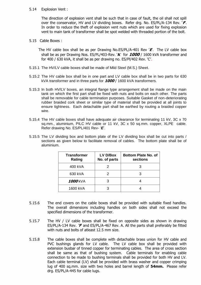
5.15.5 The LV dividing box and bottom plate of the LV dividing box shall be cut into parts /
sections as given below to facilitate removal of cables. The bottom plate shall be of aluminium.
Transformer Rating
LV D/Box No. of parts
Bottom Plate No. of sections
400 kVA 2 3
630 kVA 2 3
1000 kVA 3 4
1600 kVA 3 4
5.15.6 The end covers on the cable boxes shall be provided with suitable fixed handles.
The overall dimensions including handles on both sides shall not exceed the specified dimensions of the transformer.
5.15.7 The HV / LV cable boxes shall be fixed on opposite sides as shown in drawing
ES/PL/A-134 Rev. ‘F’ and ES/PL/A-467 Rev. A. All the parts shall preferably be fitted with nuts and bolts of atleast 12.5 mm size.
5.15.8 The cable boxes shall be complete with detachable brass union for HV cable and
PVC bushings glands for LV cable. The LV cable box shall be provided with extension busbar of tinned copper for terminating cables. The area of cross section
shall be same as that of bushing system. Cable terminals for enabling cable connection to be made to bushing terminals shall be provided for both HV and LV. Each cable terminal (LV) shall be provided with brass washer and copper crimping
lug of 400 sq.mm. size with two holes and barrel length of 54mm. Please refer drg. ES/PL/A-445 for cable lugs.

5.15.9 The cable boxes shall be suitable to take the following cable which will approach the
boxes vertically from the bottom and shall be of directly attached type.
Transformer H.V. side L.V. side
400kVA 3C/70 Sq.mm Al.,
PILC OR 3C x 50 sq.mm. Cu., XLPE
4 nos. 1C/400 Sq.mm. XLPE Copper
conductor cable (1 set)
630 kVA - do - 7 nos. 1C/400 Sq.mm. XLPE Copper
conductor cable (2 Set)
1000 kVA -do- 11 nos. 1C/400 Sq.mm. XLPE
Copper conductor cable. (3 sets)
1600 kVA - do - 22 nos. 1C/400 Sq.mm. XLPE Copper conductor cable (2 cable
boxes) 6 sets (3 sets of 11 nos. in each cable box)
1600 kVA transformer shall have two LV dividing boxes. (Refer drg. No.ES/PL/A-467 Rev. A). Each box shall have 11 nos. of 1C x 400 sq.mm. XLPE copper conductor cables.
(refer drg. No. ES/PL/A-467 Rev. A).
5.15.10 The cable boxes shall be suitable of being detached from the main tank body.
5.15.11 The fixing arrangement of the terminal plate shall be independent of that of the
cable boxes, so that no quantity of the transformer oil has to be removed while
detaching cable boxes. 5.15.12 Suitable wooden cleating arrangement for supporting the H.V. as well as L.V. cables
in vertical position shall be provided, so that H.V & L.V. bushings will not be burdened with the weight of the cable. Please refer drawing no. ES/Pl –402 Rev. ‘C’ and ES/PL-403 Rev A.
5.15.13 L.V busbar shall be supported using epoxy insulator from the top side inside the LV
dividing box.
5.15.14 Height of the centre line of HV/LV terminals from the surface of the foundation shall be 1500 mm +/- 5%, so as to enable the transformer (of any make/size) to be
replaced without any alteration to the underground cable connection. 5.16 Canopy :
The HV/LV boxes shall be provided with removable slanted (outwards) canopy of 3 mm thick M.S. sheet for protection from rain water accumulating on it. Canopy shall cover complete HV/LV dividing box.
The canopies shall be fixed with hinges on top plate in such a way that the bolts are
not required to be loosened / removed for removing canopies.
5.17 Radiators :
a) The radiators shall be of detachable type. The radiators shall be positioned in such a manner so as to maintain proper balance and facilitate easy maintenance. Radiator valves at each post shall be provided.
b) A detailed calculation of radiating surface vis-à-vis losses to be dissipated shall be forwarded in the course of order by successful tenderer.
5.18 Inspection chamber :
The inspection chamber is to be provided between transformer tank and HV/LV dividing box with an inspection cover with a suitable handle.
5.19 Additional neutral :
Two separate neutrals shall be brought out from main neutral busbar, one for taking
out the neutral for 3 phase four wire system and the other additional neutral for additional earthing. A porcelain bushing of same ampere rating as that of LV phase bushing shall be provided on additional neutral. The additional neutral shall be in
line with the LV terminals and on left hand side of L.V. Dividing box when seen from L.V. side. The additional neutral shall be protected by a removable cover (hood) of M.S. outside the tank for earthing the star point of the LV side. An Aluminium plate
with 60 mm circular opening shall be provided at the bottom of the hood for inserting G.I. earthing wire. Crimping type copper lug of size 400 sq.mm. shall be provided on the additional neutral bushing.
5.20 Gas Actuated Relay : Buchholz relay of the double float type conforming to IS 3637-1966 to trip out the
transformer in case of a major internal fault shall be provided for 1600 kVA transformer only.
5.21 Special Requirement :
a) Impedance voltage shall be of 4.75% at rated voltage of 11kV.
b) The short circuit level shall be 250 MVA at 11kV
c) As per clause 7.10.2 of IS:1180, the permissible temperature rise of the winding shall not exceed 45o C when measured by resistance method. The temperature rise of the top oil shall not exceed 40oC when measured by thermometer over a maximum ambient temperature at 50o C.
d) The actual no-load and total losses shall not exceed the guaranteed value.
(tolerance clause of I.S. not applicable). No load losses measured at 110% rated voltage shall also not exceed the respective guaranteed values.
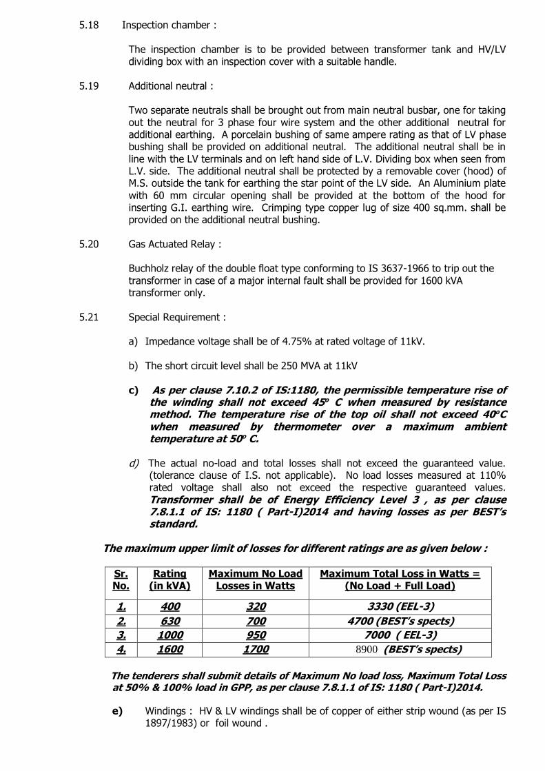
Transformer shall be of Energy Efficiency Level 3 , as per clause 7.8.1.1 of IS: 1180 ( Part-I)2014 and having losses as per BEST’s standard.
The maximum upper limit of losses for different ratings are as given below :
Sr. No.
Rating (in kVA)
Maximum No Load Losses in Watts
Maximum Total Loss in Watts = (No Load + Full Load)
1. 400 320 3330 (EEL-3)
2. 630 700 4700 (BEST’s spects)
3. 1000 950 7000 ( EEL-3)
4. 1600 1700 8900 (BEST’s spects)
The tenderers shall submit details of Maximum No load loss, Maximum Total Loss
at 50% & 100% load in GPP, as per clause 7.8.1.1 of IS: 1180 ( Part-I)2014.
e) Windings : HV & LV windings shall be of copper of either strip wound (as per IS 1897/1983) or foil wound .
f) The temperature class of insulation of winding shall be `A’ (refer clause no.6 of IS 2026 Part I). The end turns of HV and LV windings shall be insulated for
protection against surges and transients.
g) Core : The core shall be stack / wound type of high grade (M4 grade or higher)
Cold Rolled Grain Oriented (CRGO) annealed steel lamination having low loss and good grain properties, coated with hot oil proof insulation, bolted together
to the frames firmly to prevent vibration and noise for item no. 1, 2, 3 and 4.
For item No.1 the core shall be high quality amorphous ribbons / metal having very low loss formed into wound cores of rectangular shape, bolted together to the frames firmly to prevent vibration or noise. The complete design of CRGO
/amorphous core must ensure permanency of the core loss with continuous working of the transformers. The core shall be treated with insulating material on both sides of each lamination. The insulating material shall be non-
hygroscopic, so that there is no possibility of moisture being absorbed by it due to the varying annual and daily temperature cycle resulting in breathing of the transformer in a humid atmosphere.
h) Manufacturers having in-house core cutting facility are desirable. If not, the
manufacturer shall have proper check on core cutting and quality monitoring of core.
i) The grade of core laminations shall be M4 or better. The tenderer shall submit
manufacturer’s test report showing the watt loss / Kg and the thickness of core
lamination, to ascertain the quality of core material. The Undertaking reserves the right to get sample of the core material tested at any government recognized laboratory.
j) The transformer core shall not be saturated for any value of V/f ratio to the
extent of 112.5% of the rated value of V/f ratio (i.e. 11000/50 due to combined
effect of voltage and frequency) upto 12.5% without injurious heating at full load conditions and will not get saturated. The flux density at normal voltage ratio shall be so chosen that the noise and vibrations are reduced. The flux
density shall not be more than 1.6 Tesla at the rated voltage and frequency. Graph of watt loss per kg v/s flux density in respect of particular core material proposed to be utilized for manufacture of transformer shall be enclosed with
the offer.
k) The tank shall be constructed with M.S. Plate with thickness not less than 5 mm
and with each side in one piece.
l) Overall Dimensions :-
I) The maximum overall height of the transformer shall not exceed 2700
mm.
II) The overall width of the transformer shall not exceed 2500 mm. when
measured from HV cable box to LV cable box including radiators. Refer drawing no.ES/PL/A-134 Rev. ‘F’ and ES/PL/A – 467 Rev. A.
m) Transport Dimensions – after removing detachable parts:-
Transport dimensions i.e. transformer width (after removing all detachable parts i.e. cable boxes, radiator, conservator, etc.) when measured from HV bushing tip to LV bushing tip (excluding the palm of LV bushing) shall not exceed 1200 mm.
for 400, 630 and 1000 kVA and for that of 1600 kVA it should not exceed 1400 mm.
n) Painting :
As per Clause 15.5 of IS:1180(Part-I)/2014, Inside of tank shall be painted with varnish or oil resistant paint. For external surfaces one coat of thermo setting powder paint or one coat of epoxy primer followed by two coats of polyurethane base paint shall be used. Table 12 of IS:1180 shall be referred to for paint thickness for normal to medium corrosive atmosphere.
o) Terminals :
I) The primary and secondary terminals shall be brought out on opposite sides of
the transformer for connection to 11 kV, 3C x 70 sq.mm. PILC/ Al or 11 kV, 3C x
50 sq.mm, XLPE/Cu. and 1C x 400 sq.mm. copper conductor unarmoured XLPE cables respectively. An additional, insulated neutral terminal properly protected by a removable cover shall be provided outside the tank for earthing the star
point of the LV side. II) The high and low voltage phase terminals shall be marked on the inside as well
as on the outside of the tank with colours red, yellow and blue, the neutral point terminal being indicated by letter `n’.
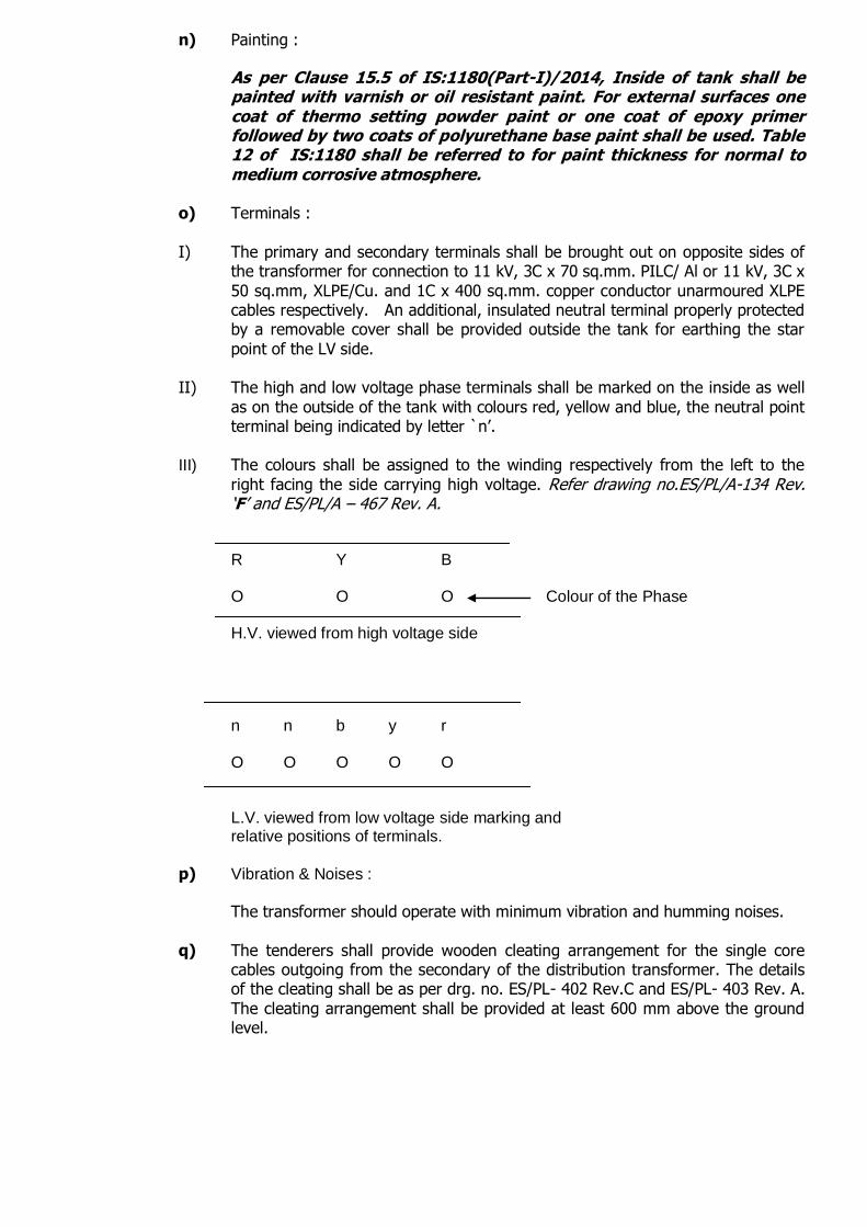
III) The colours shall be assigned to the winding respectively from the left to the
right facing the side carrying high voltage. Refer drawing no.ES/PL/A-134 Rev. ‘F’ and ES/PL/A – 467 Rev. A.
R Y B O O O Colour of the Phase H.V. viewed from high voltage side n n b y r O O O O O L.V. viewed from low voltage side marking and relative positions of terminals.
p) Vibration & Noises :
The transformer should operate with minimum vibration and humming noises.
q) The tenderers shall provide wooden cleating arrangement for the single core cables outgoing from the secondary of the distribution transformer. The details of the cleating shall be as per drg. no. ES/PL- 402 Rev.C and ES/PL- 403 Rev. A.
The cleating arrangement shall be provided at least 600 mm above the ground level.
5.22 Miscellaneous Requirements :
1) The neutral conductor and terminal of the transformer shall be designed for
earth fault current for one second.
2) Insulation liquid – Mineral oil as per IS 335: 1993 (with latest amendment).
3) Bushings - The metallic part of bushing shall be of copper and the insulating part shall be of porcelain.
a) The HV bushing shall be of rating 12kV/250Amp as per IS :9147-1979 b) As per 10.1.5 of IS:1180 ( Part-I)2014,the LV bushings with copper
stem shall be of the rating 1 kV and shall be in accordance with of IS 3347 (Part-1/Sec-2)-1979.
4) The HV bushing shall be of completely immersed type as per clause no.2.18 of
IS:2099/1986. 5) Bushings - Rating
a) Rated voltage 12 kV for HV and 1 kV for LV.
b) Rated Current for – 400, 630 kVA transformer – HV 250 Amps, LV 1000 A.
1000 kVA transformer - HV 250 Amps, LV 2000 A. 1600 kVA transformer – HV 250 Amps and LV 2000 A.
c) Rated short time current of both HV and LV bushings shall be 25 times the rated current for 1 second.
d) Rated frequency – 50 Hz.
6) Bushings – Operating conditions –
a) Ambient minimum – 28O C.
b) Immersion medium – Maximum 100O C.
5.23 Drawings : 5.23.1 Tenderer shall submit in quadruplicate on the following drawings alongwith the
quotation: a) Dimensional drawing of the transformer offered.
b) Diagram of connection.
c) Dimensional drawings showing the HV and LV cable boxes offered. d) Dimensional drawings of HV and LV bushing alongwith metal parts.
e) Anti-theft arrangement for drain valve and filter valve, breather, etc.
5.23.2 The drawings shall be to scale and fully detailed. All important dimensions shall be given and materials of each component shall be indicated.
5.23.3 The drawings shall be submitted within 2 weeks from the date of receipt of acceptance letter.
5.23.4 The drawings shall be submitted and get approved within 4 weeks from the date of
submission of drawings. It will be the responsibility of successful tenderer to get the
drawings approved in the period stipulated above and any delay will be adjusted with the period for offering prototype for inspection and testing.
5.23.5 The successful tenderer will be required to supply copies of final drawings in quadruplicate as specified above. A soft copy of the drawings shall also be submitted in two duplicate C.D.
5.24 In the Section-9 of specification, the tenderer is required to submit the guaranteed
performance and particulars (GPP).The transformers shall be as per our requirement regarding the essential parameters listed below. If there is any deviation from our requirement or if the tenderer does not furnish following parameters, no
correspondence will be made after opening of the tender and the offer is liable to be overlooked.
1) Vector Group and Symbol (The vector group shall be Dyn11)
2) Maximum temperature rise at rated kVA
As per IS 1180 clause 7.10.2, temperature of winding shall not exceed 45O C and temperature of top oil shall not exceed 40O C over maximum ambient temperature of 50O C.
3) Maximum No load losses (No tolerance allowed)
as per Annexure `F’.
4) Maximum full load ( 100 %) losses., (No tolerance allowed) as per Annexure `F’
5) Maximum total losses (No tolerance allowed)
as per Annexure `F’.
6) Impedance voltage at rated load at 11kV in percentage.
(Impedance voltage at the rated current shall be 4.75% with IS tolerance at
11kV). 7) Thickness of transformer tank
(The thickness of transformer tank shall be greater than or equal to 5mm). 8) Overall dimensions
(The overall length or width of the transformer shall be less than or equal to 2.5 mtrs. and the overall height shall be less than or equal to 2.7 mtrs.)
9) Transport dimensions i.e. the dimensions after removing all the detachable parts such as HV/LV dividing boxes, radiators etc. (The transformer length or width shall be less than or equal to 1.2 mtrs. after
removing the detachable parts for 400,630, 1000 kVA and 1.4 mtrs for 1600 kVA.)
10) Height of the centre line of terminals from the foundation level (This height shall be exactly 1.5 mtrs. with max. of +/-5% tolerance for all the ratings of transformers)
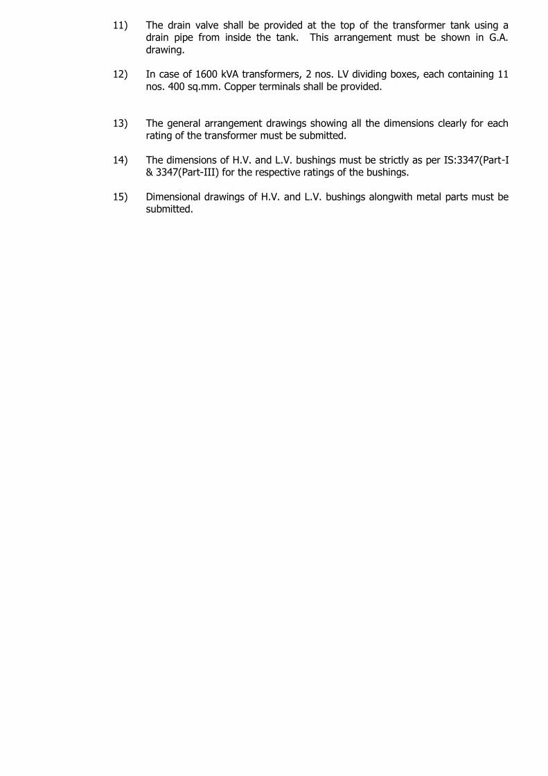
11) The drain valve shall be provided at the top of the transformer tank using a drain pipe from inside the tank. This arrangement must be shown in G.A.
drawing. 12) In case of 1600 kVA transformers, 2 nos. LV dividing boxes, each containing 11
nos. 400 sq.mm. Copper terminals shall be provided.
13) The general arrangement drawings showing all the dimensions clearly for each rating of the transformer must be submitted.
14) The dimensions of H.V. and L.V. bushings must be strictly as per IS:3347(Part-I & 3347(Part-III) for the respective ratings of the bushings.
15) Dimensional drawings of H.V. and L.V. bushings alongwith metal parts must be submitted.

SECTION-6 : TESTING AND INSPECTION
6.1 Tests :
6.1.1 The transformers shall be subjected to the tests as specified in clause 21.2 of IS: 1180(Part-I)/2014 and Section- 16.1.2 of IS: 2026(Part-I)/1977 at the
manufacturer’s works and at BES&T’s testing laboratory
The Temperature Rise test (type test) as per IS:2026(Part-2)/1977 on prototype transformer and Routine tests on prototype as well as on transformers to be supplied in lots shall be witnessed by the inspecting officers of the undertaking and shall be carried out on FREE OF COST basis by the manufacturer at his works.
6.1.1.1 I) Routine tests as per IS:1180 (Part-I)/2014 and IS 2026 (Part I) on all
transformers –
a) Measurement of winding resistance.[IS:2026(Part-I)] b) Measurement of Voltage Ratio, Polarity and check of phase
displacement. [IS:2026(Part-I)] c) Measurement of short circuit impedance ( principal tapping, when
applicable) and load loss at 50% and 100% load [IS:2026(Part-I)]
d) Load Losses (the frequency correction factor as given at 6.1.1.1.1 shall be applied to the stray losses component calculated).
e) Measurement of No-load losses and no-load current :- While carrying
out the no load losses Measurement test, the ratio V rated : f rated shall be maintained by adjusting V test according to f test. (V rated = Rated voltage, V test = Test voltage, f rated = Rated frequency. f test
= Test frequency). (the frequency correction factor as given at 6.1.1.1.2 shall be applied to the measured No load losses). [IS:2026(Part-I)]
f) Measurement of Insulation resistance. [IS:2026(Part-I)] g) Measurement of Induced over voltage withstand test.
[IS:2026(Part-3)] h) Separate source voltage withstand test. [IS:2026(Part-3)] i) Magnetic balance test on HV and LV side. j) Polarisation index.
k) BD value of oil l) Pressure test IS:1180(Part-I)/2014 clause 21.5 m) Oil leakage test IS:1180(Part-I)/2014 clause 21.5
6.1.1.1.1 Stray losses at rated frequency
Rated Frequency 2 = Stray losses at test frequency x Test Frequency
6.1.1.1.2 Actual No load losses at rated frequency
Measured No load losses Rated Frequency 2 = x 2 Test Frequency
Measured No load losses Rated Frequency
+ x 2 Test Frequency
While carrying out the tests for measuring no load losses the ratio of rated
Voltage : rated frequency shall be maintained by adjusting the test voltage
according to the test frequency.
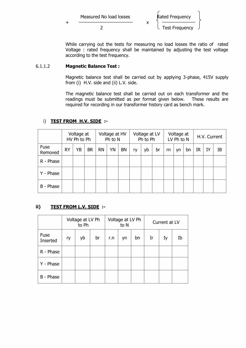
6.1.1.2 Magnetic Balance Test :
Magnetic balance test shall be carried out by applying 3-phase, 415V supply from (i) H.V. side and (ii) L.V. side.
The magnetic balance test shall be carried out on each transformer and the readings must be submitted as per format given below. These results are required for recording in our transformer history card as bench mark.
i) TEST FROM H.V. SIDE :-
Voltage at HV Ph to Ph
Voltage at HV Ph to N
Voltage at LV Ph to Ph
Voltage at LV Ph to N
H.V. Current
Fuse
Removed RY YB BR RN YN BN ry yb br rn yn bn IR IY IB
R - Phase
Y - Phase
B - Phase
ii) TEST FROM L.V. SIDE :-
Voltage at LV Ph to Ph
Voltage at LV Ph to N
Current at LV
Fuse
Inserted ry yb br r.n yn bn Ir Iy Ib
R - Phase
Y - Phase
B - Phase
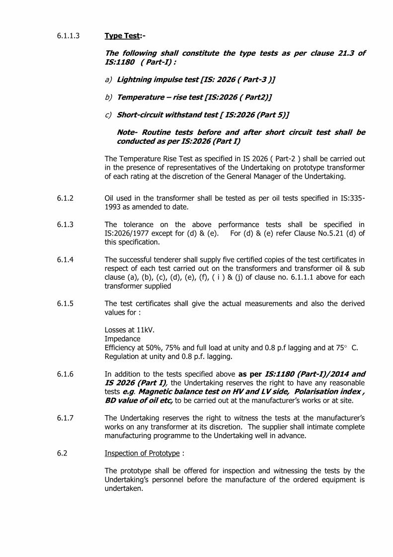
6.1.1.3 Type Test:-
The following shall constitute the type tests as per clause 21.3 of IS:1180 ( Part-I) : a) Lightning impulse test [IS: 2026 ( Part-3 )] b) Temperature – rise test [IS:2026 ( Part2)]
c) Short-circuit withstand test [ IS:2026 (Part 5)]
Note- Routine tests before and after short circuit test shall be conducted as per IS:2026 (Part I)
The Temperature Rise Test as specified in IS 2026 ( Part-2 ) shall be carried out in the presence of representatives of the Undertaking on prototype transformer
of each rating at the discretion of the General Manager of the Undertaking.
6.1.2 Oil used in the transformer shall be tested as per oil tests specified in IS:335-1993 as amended to date.
6.1.3 The tolerance on the above performance tests shall be specified in IS:2026/1977 except for (d) & (e). For (d) & (e) refer Clause No.5.21 (d) of this specification.
6.1.4 The successful tenderer shall supply five certified copies of the test certificates in
respect of each test carried out on the transformers and transformer oil & sub clause (a), (b), (c), (d), (e), (f), ( i ) & (j) of clause no. 6.1.1.1 above for each
transformer supplied 6.1.5 The test certificates shall give the actual measurements and also the derived
values for :
Losses at 11kV.
Impedance
Efficiency at 50%, 75% and full load at unity and 0.8 p.f lagging and at 75 C. Regulation at unity and 0.8 p.f. lagging.
6.1.6 In addition to the tests specified above as per IS:1180 (Part-I)/2014 and
IS 2026 (Part I), the Undertaking reserves the right to have any reasonable tests e.g. Magnetic balance test on HV and LV side, Polarisation index , BD value of oil etc, to be carried out at the manufacturer’s works or at site.
6.1.7 The Undertaking reserves the right to witness the tests at the manufacturer’s
works on any transformer at its discretion. The supplier shall intimate complete manufacturing programme to the Undertaking well in advance.
6.2 Inspection of Prototype :
The prototype shall be offered for inspection and witnessing the tests by the
Undertaking’s personnel before the manufacture of the ordered equipment is undertaken.

6.3 Rejection of Prototype / Lot :
The prototype or any lot is liable for rejection during inspection by the Undertaking’s officers at the works of the manufacturer, if test results are not
satisfactory and the permissible tolerances are exceeded or if there are deviations from our specification or if the equipment offered is found to be incomplete. In such cases the manufacturer has to offer fresh prototype / lot for
re-inspection at their works. The re-inspection charges shall include salary and allowances of the officers and to and fro air / first class AC rail fare expenses. The re-inspection charges shall be recovered from outstanding payment to be
made to the manufacturer.
6.4 Manual for Installation, Maintenance & Operation :
Three copies of Manual for installation, maintenance and operation of transformers shall be forwarded along with each lot of transformer supplied by the Manufacturer to the accepting authority. Also, a soft copy of Manual in the
form of CD (3 nos.) shall be submitted to Planning (M) department.
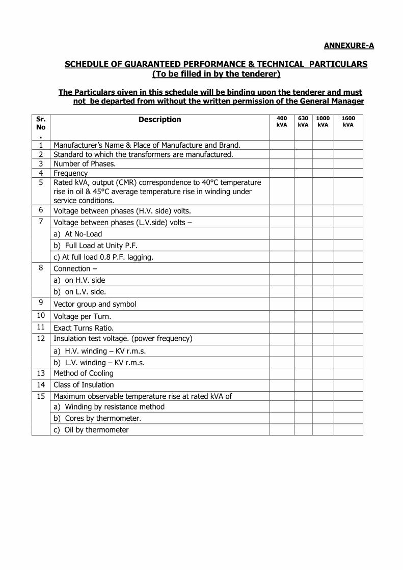
ANNEXURE-A
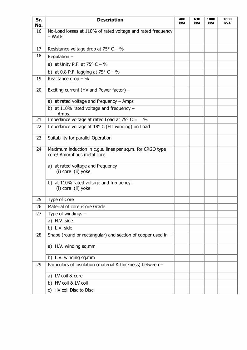
SCHEDULE OF GUARANTEED PERFORMANCE & TECHNICAL PARTICULARS (To be filled in by the tenderer)
The Particulars given in this schedule will be binding upon the tenderer and must not be departed from without the written permission of the General Manager
Sr. No
.
Description 400 kVA
630 kVA
1000kVA
1600 kVA
1 Manufacturer’s Name & Place of Manufacture and Brand.
2 Standard to which the transformers are manufactured.
3 Number of Phases.
4 Frequency
5 Rated kVA, output (CMR) correspondence to 40°C temperature
rise in oil & 45°C average temperature rise in winding under service conditions.
6 Voltage between phases (H.V. side) volts.
7 Voltage between phases (L.V.side) volts –
a) At No-Load
b) Full Load at Unity P.F.
c) At full load 0.8 P.F. lagging.
8 Connection –
a) on H.V. side
b) on L.V. side.
9 Vector group and symbol
10 Voltage per Turn.
11 Exact Turns Ratio.
12 Insulation test voltage. (power frequency)
a) H.V. winding – KV r.m.s.
b) L.V. winding – KV r.m.s.
13 Method of Cooling
14 Class of Insulation
15 Maximum observable temperature rise at rated kVA of
a) Winding by resistance method
b) Cores by thermometer.
c) Oil by thermometer
Sr. No.
Description 400 kVA
630 kVA
1000kVA
1600 kVA
16 No-Load losses at 110% of rated voltage and rated frequency – Watts.
17 Resistance voltage drop at 75° C – %
18 Regulation –
a) at Unity P.F. at 75° C – %
b) at 0.8 P.F. lagging at 75° C – %
19 Reactance drop – %
20 Exciting current (HV and Power factor) –
a) at rated voltage and frequency – Amps
b) at 110% rated voltage and frequency – Amps.
21 Impedance voltage at rated Load at 75° C = %
22 Impedance voltage at 18° C (HT winding) on Load
23 Suitability for parallel Operation
24 Maximum induction in c.g.s. lines per sq.m. for CRGO type core/ Amorphous metal core.
a) at rated voltage and frequency (i) core (ii) yoke
b) at 110% rated voltage and frequency – (i) core (ii) yoke
25 Type of Core
26 Material of core /Core Grade
27 Type of windings –
a) H.V. side
b) L.V. side
28 Shape (round or rectangular) and section of copper used in –
a) H.V. winding sq.mm
b) L.V. winding sq.mm
29 Particulars of insulation (material & thickness) between –
a) LV coil & core
b) HV coil & LV coil
c) HV coil Disc to Disc
Sr.
No.
Description 400
kVA
630
kVA
1000
kVA
1600
kVA
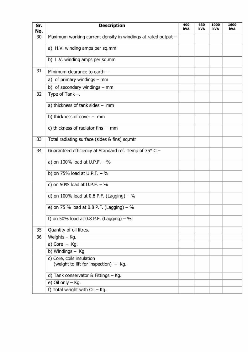
30 Maximum working current density in windings at rated output –
a) H.V. winding amps per sq.mm
b) L.V. winding amps per sq.mm
31 Minimum clearance to earth –
a) of primary windings – mm
b) of secondary windings – mm
32 Type of Tank –.
a) thickness of tank sides – mm
b) thickness of cover – mm
c) thickness of radiator fins – mm
33 Total radiating surface (sides & fins) sq.mtr
34 Guaranteed efficiency at Standard ref. Temp of 75° C –
a) on 100% load at U.P.F. – %
b) on 75% load at U.P.F. – %
c) on 50% load at U.P.F. – %
d) on 100% load at 0.8 P.F. (Lagging) – %
e) on 75 % load at 0.8 P.F. (Lagging) – %
f) on 50% load at 0.8 P.F. (Lagging) – %
35 Quantity of oil litres.
36 Weights – Kg.
a) Core – Kg.
b) Windings – Kg.
c) Core, coils insulation
(weight to lift for inspection) – Kg.
d) Tank conservator & Fittings – Kg.
e) Oil only – Kg.
f) Total weight with Oil – Kg.
Sr. No.
Description 400 kVA
630 kVA
1000 kVA
1600 kVA
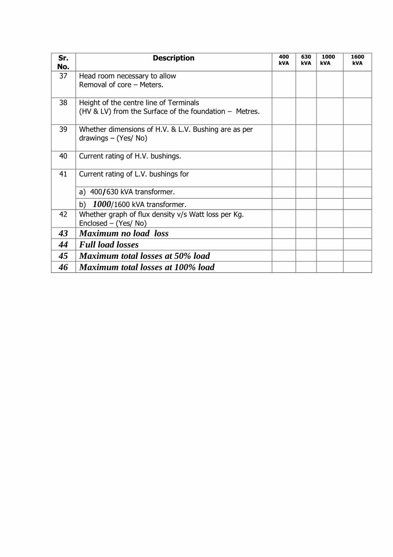
37 Head room necessary to allow Removal of core – Meters.
38 Height of the centre line of Terminals (HV & LV) from the Surface of the foundation – Metres.
39 Whether dimensions of H.V. & L.V. Bushing are as per drawings – (Yes/ No)
40 Current rating of H.V. bushings.
41 Current rating of L.V. bushings for
a) 400/630 kVA transformer.
b) 1000/1600 kVA transformer.
42 Whether graph of flux density v/s Watt loss per Kg.
Enclosed – (Yes/ No)
43 Maximum no load loss
44 Full load losses
45 Maximum total losses at 50% load
46 Maximum total losses at 100% load
ANNEXURE-C PRICE VARIATION CLAUSE FOR ONAN TYPE DIST. TRANSFORMER
(Of Ratings upto 2500 KVA and Voltages upto 33 kV)
supplied against domestic contracts
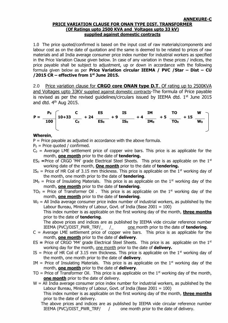
1.0 The price quoted/confirmed is based on the input cost of raw materials/components and
labour cost as on the date of quotation and the same is deemed to be related to prices of raw materials and all India average consumer price index number for industrial workers as specified in the Price Variation Clause given below. In case of any variation in these prices / indices, the
price payable shall be subject to adjustment, up or down in accordance with the following formula given below as per Price Variation circular IEEMA / PVC /Star – Dist – CU /2015 CR – effective from 1st June 2015.
2.0 Price variation clause for CRGO core ONAN type D.T. Of rating up to 2500KVA
and Voltages upto 33KV supplied against domestic contracts-The formula of Price payable is revised as per the revised guidelines/circulars issued by IEEMA dtd. 1st June 2015 and dtd. 4th Aug 2015.
P = P0
10+33 C
+ 24 ES
+ 9 IS
+ 4 IM
+ 5 TO
+ 15 W
100 C0 ES0 IS0 IM0 TO0 W0
Wherein, P = Price payable as adjusted in accordance with the above formula. P0 = Price quoted / confirmed. C0 = Average LME settlement price of copper wire bars. This price is as applicable for the
month, one month prior to the date of tendering. ES0 =Price of CRGO ‘M4’ grade Electrical Steel Sheets. This price is as applicable on the 1st
working date of the month, One month prior to the date of tendering.
IS0 = Price of HR Coil of 3.15 mm thickness. This price is applicable on the 1st working day of the month, one month prior to the date of tendering.
IM0 = Price of Insulating Materials. This price is as applicable on the 1st working day of the
month, one month prior to the date of tendering. TO0 = Price of Transformer Oil . This price is as applicable on the 1st working day of the
month, one month prior to the date of tendering.
W0 = All India average consumer price index number of industrial workers, as published by the Labour Bureau, Ministry of Labour, Govt. of India (Base 2001 = 100)
This index number is as applicable on the first working day of the month, three months
prior to the date of tendering. The above prices and indices are as published by IEEMA vide circular reference number IEEMA (PVC)/DIST_PWR_TRF/_ /_ one month prior to the date of tendering.
C = Average LME settlement price of copper wire bars. This price is as applicable for the month, one month prior to the date of delivery.
ES = Price of CRGO ‘M4’ grade Electrical Steel Sheets. This price is as applicable on the 1st
working day for the month, one month prior to the date of delivery. IS = Price of HR Coil of 3.15 mm thickness. This price is applicable on the 1st working day of
the month, one month prior to the date of delivery.
IM = Price of Insulating Materials. This price is as applicable on the 1st working day of the month, one month prior to the date of delivery.
TO = Price of Transformer Oil. This price is as applicable on the 1st working day of the month,
one month prior to the date of delivery. W = All India average consumer price index number for industrial workers, as published by the
Labour Bureau, Ministry of Labour, Govt. of India (Base 2001 = 100)
This index number is as applicable on the first working day of the month, three months prior to the date of delivery.
The above prices and indices are as published by IEEMA vide circular reference number IEEMA (PVC)/DIST_PWR_TRF/ / one month prior to the date of delivery.

3.0 Price variation clause for amorphous type D.T. Of rating up to 2500KVA and Voltages upto 33KV supplied against domestic contracts - In the absence of IEEMA price variation clause
for amorphous core type transformers, PV clause is formulated for the same, in line with existing IEEMA P.V. clause for copper wound distribution transformer with CRGO core. In the price variation clause for copper wound distribution transformers with amorphous core,
amorphous core component i.e. ESA / ESA0 is considered as unity. The formula is as follows :
P = P0
10+33 C
+ 24 ESA
+ 9 IS
+ 4 IM
+ 5 TO
+ 15 W
100 C0 ESA0 IS0 IM0 TO0 W0
Note: In the existing PV clause, ES and ES0 represents CRGO component whereas in proposed PV clause, ESA and ESA0 represents amorphous component. In the above clause ESA / ESA0 considered as unity i.e. ESA = ESA0, till such time IEEMA comes
out with a price variation index for amorphous material.
Wherein,
P = Price payable as adjusted in accordance with the above formula. P0 = Price quoted / confirmed. C0 = Average LME settlement price of copper wire bars. This price is as applicable for the
month, one month prior to the date of tendering. ESA0 = Price of core with Amorphous material. (This price is as applicable on the 1st
working date of the month, one month prior to the date of tendering).
IS0 = Price of HR Coil of 3.15 mm thickness. This price is applicable on the 1st working day of the month, one month prior to the date of tendering.
IM0 = Price of Insulating Materials. This price is as applicable on the 1st working day of the month, one month prior to the date of tendering.
TO0 = Price of Transformer Oil . This price is as applicable on the 1st working day of the month, one month prior to the date of tendering.
W0 = All India average consumer price index number of industrial workers, as published by the
Labour Bureau, Ministry of Labour, Govt. of India (Base 2001 = 100) This index number is as applicable on the first working day of the month, three months
prior to the date of tendering.
The above prices and indices are as published by IEEMA vide circular reference number IEEMA (PVC)/DIST_PWR_TRF/_ /_ one month prior to the date of tendering.
C = Average LME settlement price of copper wire bars. This price is as applicable for the
month, one month prior to the date of delivery. ESA = Price of core with Amorphous material. This price is as applicable on the 1st
working day for the month, one month prior to the date of delivery.
IS = Price of HR Coil of 3.15 mm thickness. This price is applicable on the 1st working day of the month, one month prior to the date of delivery.
IM = Price of Insulating Materials. This price is as applicable on the 1st working day of the
month, one month prior to the date of delivery. TO = Price of Transformer Oil. This price is as applicable on the 1st working day of the month,
one month prior to the date of delivery.
W = All India average consumer price index number for industrial workers, as published by the Labour Bureau, Ministry of Labour, Govt. of India (Base 2001 = 100)
This index number is as applicable on the first working day of the month, three months
prior to the date of delivery. The above prices and indices are as published by IEEMA vide circular reference number
IEEMA (PVC)/DIST_PWR_TRF/ / one month prior to the date of delivery.
CONDITIONS FOR OPERATION OF PRICE VARIATION CLAUSE
1. The amount of price variation to be reimbursed or claimed as a refund on account of
variation in prices of raw materials and All India Average Consumer Price Index No. for Industrial Workers, shall be worked out on the basis of aforesaid Price Variation Clause and that too for the quantity of Distribution Transformers supplied as per the contractual delivery period.
2. The date of delivery is the date on which the Transformer is notified as being ready for
inspection/dispatch (in the absence of such notification, the date of manufacturer's
Dispatch Note is to be considered as the date of delivery) or the contracted delivery date (including any agreed extension thereto), whichever is earlier.
3. The Price Variation Clause is operative both ways i.e. if the actual price variation admissible is upward, the payment on account of price variation shall be released to the supplier and if it is downward, the Undertaking shall be entitled to recover the same
from any amount due to the supplier.
4. The payment shall be released for Distribution Transformers supplied as per the
delivery schedule based on the quoted price as per the Undertaking’s Payment Terms as shown in Schedule-IX attached to the Tender Documents.
5. The amount of price variation to be reimbursed or claimed on account of upward/downward price variation, shall be worked out and the necessary price
amendments will be released after regular interval of 12 months from the date of release of Purchase Order for the quantity supplied and accepted.
6. Variation in prices of finished product due to change in Statutory Levies, etc. are considered only if the tenderer specifically mentions ‘Taxes & Statutory Levies as applicable’ in their quotation and mention specific rates/percentage of these taxes
applicable at the time of submitting quotation and produces necessary documentary evidence of such variation at the time of claiming the payments.
Variation in price due to Statutory Levies, etc. on the revised basic price of finished
product on the basis of Price Variation formula stipulated above, will be worked out and necessary Amendment Form will be issued. If the variation in price is upward, the supplier shall have to submit the Tax invoice (supplementary) for the difference in rate
due to price variation, based on which payment will be released.
However, if the variation in price is downward, the Undertaking shall recover the same
amount inclusive of statutory component, etc. as per Amendment Form issued to the supplier from any amount due to the supplier. The supplier shall have to follow up with the concerned Government/Municipal authorities for claim settlement of statutory
components such as Excise Duty, VAT, Octroi, etc.
7. If the delivery is delayed by the supplier, then the amount of price variation will be
worked out on the basis of contractual delivery schedule (and not as per the actual delivery schedule), irrespective of upward/downward price variation.
8. The tenderers, who fail to accept the aforesaid Price Variation Clause shall be considered as Non-responsive and their price bids shall not be opened.
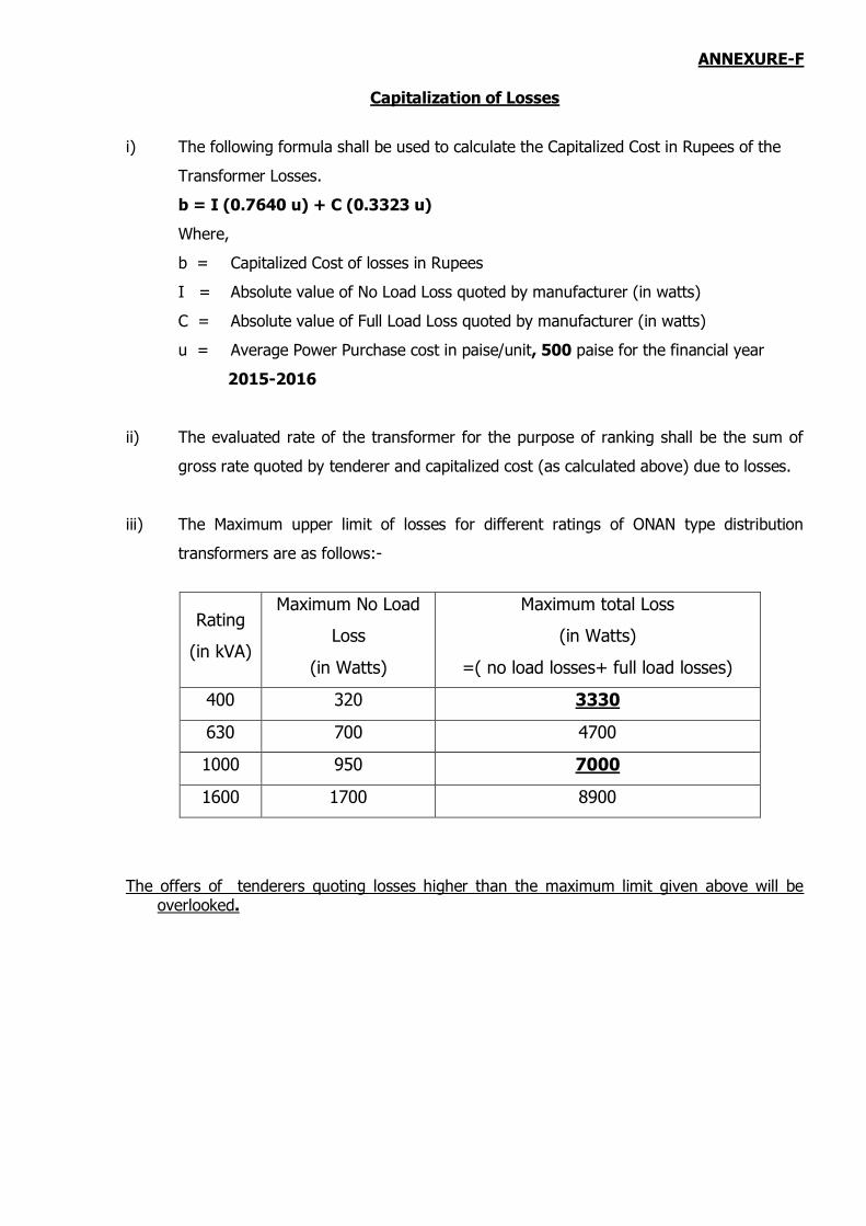
ANNEXURE-F
Capitalization of Losses
i) The following formula shall be used to calculate the Capitalized Cost in Rupees of the
Transformer Losses.
b = I (0.7640 u) + C (0.3323 u)
Where,
b = Capitalized Cost of losses in Rupees
I = Absolute value of No Load Loss quoted by manufacturer (in watts)
C = Absolute value of Full Load Loss quoted by manufacturer (in watts)
u = Average Power Purchase cost in paise/unit, 500 paise for the financial year
2015-2016
ii) The evaluated rate of the transformer for the purpose of ranking shall be the sum of
gross rate quoted by tenderer and capitalized cost (as calculated above) due to losses.
iii) The Maximum upper limit of losses for different ratings of ONAN type distribution
transformers are as follows:-
Rating
(in kVA)
Maximum No Load
Loss
(in Watts)
Maximum total Loss
(in Watts)
=( no load losses+ full load losses)
400 320 3330
630 700 4700
1000 950 7000
1600 1700 8900
The offers of tenderers quoting losses higher than the maximum limit given above will be overlooked.

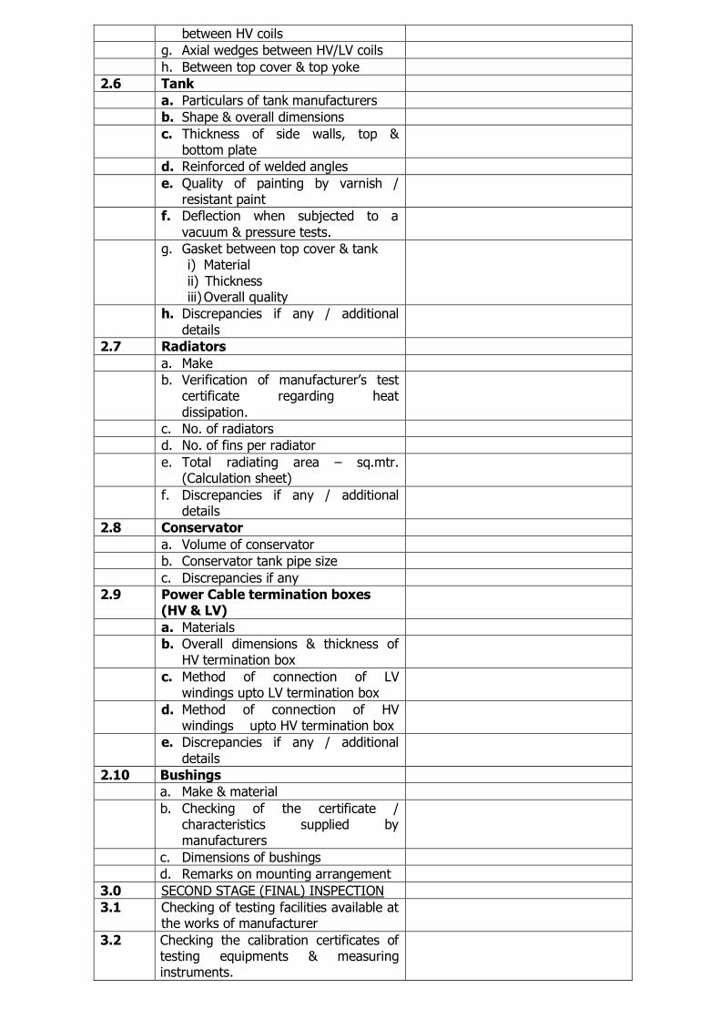
ANNEXURE ‘J’
CHECK LIST FOR STAGE INSPECTION FOR PROTOTYPE DISTRIBUTION TRANSFORMER
(To be filled after placing the purchase order)
Sr. No. Particulars Observations
1.0 PARTICULARS OF FIRM & EQUIPMENT ORDERED
Name of the firm
Factory address
A.L. / P.O.No.
Rating of transformer ordered
Quantity on order
Sr.No. of transformer inspected
2.0 FIRST STAGE INSPECTION
2.1 Inspection of core materials
2.1.1 Material source documents & test certificates
a. Source of supply / make
b. Firm’s purchase order No., date &
quantity purchased
c. Suppliers dispatch details and excise gate pass No. etc.
d. Test certificates / material characteristics supplied by the manufacturer
2.1.2 Remarks regarding quality of core material
2.2 Core Constructions
a. No. of steps
b. Dimensions of steps
c. Core diameter (mm.)
d. Core Area (Sq.mm.)
e. Core length (leg Centre) - mm
f. Core weight – Kg.
g. Window height - mm
h. Core details (stepwise)
i. Total cross section area of core sq.mm.
j. Effective core area sq.mm.
k. Core length, width and cross section
area (stepwise)
l. Clamping arrangement i) Channel size
ii) Bolt size, material & quality iii) Painting of channel iv) Tie rod size, material & quantity
m. Arrangement of taking out L.V. connections
n. Whether necessary reinforcement is
done for above.
o. Support channels for core base & bottom yoke (flat or cut channel not
accepted)

p. Remarks regarding rusting & smoothness of core
q. Discrepancies if any / additional
details
2.3 Inspection of winding materials and winding construction (HV &
LV)
a. Source of supply / make
b. Firm’s purchase order No., date &
quantity purchased
c. Suppliers dispatch details and excise gate pass No. etc.
d. Test certificates / material characteristic supplied by the manufacturer
e. material used for HV windings
f. Testing carried out if any and
remarks
g. Size & cross section of windings i) HV winding
ii) LV winding
h. Current density i) HV
ii) LV
i. Remarks on quality of winding materials
j. L.V. windings arrangement (construction details)
k. HV winding arrangement (construction details)
l. No. of H.V. coils
m. Quality of HV coil joints
n. Neutral position
o. Discrepancies if any / additional
details
2.4 Insulation Materials
a. Source of supply / make
b. Firm’s purchase order No., date & quantity purchased
c. Suppliers dispatch details and excise gate pass No. etc.
d. Test certificates / material
characteristic supplied by the manufacturer
e. Type of paper insulation and wood for top & bottom yoke insulation
f. Testing carried out if any & remarks
g. Remarks on quality of paper insulation, press board, wood for yoke insulation etc.
2.5 Clearances
a. L.V. to core (Radial)
b. Between L.V. & H.V. (Radial)
c. Phase to Phase (HV)
d. Between windings & body
e. End insulation
f. Thickness of locking spacers
between HV coils
g. Axial wedges between HV/LV coils
h. Between top cover & top yoke
2.6 Tank
a. Particulars of tank manufacturers
b. Shape & overall dimensions
c. Thickness of side walls, top & bottom plate
d. Reinforced of welded angles
e. Quality of painting by varnish / resistant paint
f. Deflection when subjected to a
vacuum & pressure tests.
g. Gasket between top cover & tank i) Material
ii) Thickness iii) Overall quality
h. Discrepancies if any / additional
details
2.7 Radiators
a. Make
b. Verification of manufacturer’s test certificate regarding heat
dissipation.
c. No. of radiators
d. No. of fins per radiator
e. Total radiating area – sq.mtr. (Calculation sheet)
f. Discrepancies if any / additional details
2.8 Conservator
a. Volume of conservator
b. Conservator tank pipe size
c. Discrepancies if any
2.9 Power Cable termination boxes (HV & LV)
a. Materials
b. Overall dimensions & thickness of HV termination box
c. Method of connection of LV windings upto LV termination box
d. Method of connection of HV windings upto HV termination box
e. Discrepancies if any / additional
details
2.10 Bushings
a. Make & material
b. Checking of the certificate / characteristics supplied by manufacturers
c. Dimensions of bushings
d. Remarks on mounting arrangement
3.0 SECOND STAGE (FINAL) INSPECTION
3.1 Checking of testing facilities available at the works of manufacturer
3.2 Checking the calibration certificates of testing equipments & measuring instruments.

3.3 Transformer Oil
a. Source of supply / manufacturer
b. Firm’s purchase order No., date &
quantity purchased
c. Suppliers dispatch details and excise gate pass No. etc.
d. Test certificates / material characteristics supplied by the manufacturer
e. Testing of oil as per specification & remarks
f. Volume of oil
g. Weight of oil
3.4 Checking of Accessories / Fitting
Inspection & confirming the details as per specification and approved drawings
a. Arrangement for movement of transformer
b. Support arrangement for termination boxes (HV & LV)
c. Terminal marking for HV & LV power
cables
d. Buchholz relay
e. Breather
f. Oil level gauges / indicators
g. Drain valve
h. Filter valve
i. Shutoff valve
j. Earthing points
k. Rollers
l. Other accessories
3.5 Painting
a. Colour (Shade as per specification)
b. Remarks on overall quality of
painting
3.6 Schedule of Tests to be carried out
Test shall be in accordance with Section-6 of this specification
D:\Shafiqa PC\REVISION IN SPECIFICATION\Rev. in spec. of ONAN DT\New