Embed Size (px)
DESCRIPTION
Technical Specification for 11kv Panel
Citation preview

POWERBOX PROJECT (ISSUE 1) SECTION 1 1/48
Section S1
TECHNICAL MANUAL
11 kV Switchboard

POWERBOX PROJECT (ISSUE 1) SECTION 1 2/48
CONTENTS
SECTION 1 – TECHNICAL 3 1.1.0 PANEL GENIE EVO SWITCHBOARD 3 1.2.0 VC2-P7 4 1.3.0 BECB – BUSBAR END CABLE BOX 6 1.4.0 BUSBAR VT 7 SUPPORT INFORMATION GENIE EVO 8 1.2 DESCRIPTION OF GENIE EVO RANGE PANELS AND SWITCHBOARD CONSTRUCTION 8 1.3 BUSBARS AND CONNECTIONS 8 1.4 CURRENT TRANSFORMERS – CIRCUIT CONNECTION 9 1.5 VOLTAGE TRANSFORMERS – CIRCUIT CONNECTION 9 1.6 VOLTAGE TRANSFORMERS – BUSBAR CONNECTION 9 1.7 CABLE EARTHING AND TESTING FACILITIES 9 1.8 BUSBAR EARTHING AND TESTING FACILITIES 10 1.9 LOW VOLTAGE WIRING 10 1.10 ANTI-CORROSION PROTECTION AND FINISHING 10 1.11 LABELLING 10 1.12 GENERAL TECHNICAL DATA 11 1.13 ADDITIONAL RELATED STANDARDS 11 1.14 WEIGHTS AND DIMENSIONS 11 SUPPORT INFORMATION SEPAM SERIES 80 12 1.15. OVERVIEW 12 1.16. BASE UNIT WITH ADVANCED USER-MACHINE INTERFACE 12 1.17. HARDWARE CHARACTERISTICS 13 1.18. ADVANCED UMI FRONT PANEL CONTROLS AND OPERATION 14 1.19. ELECTRICAL CHARACTERISTICS 15 SUPPORT INFORMATION SFT2841 SETTING AND OPERATING SOFTWARE 16 1.20. OVERVIEW 16
POWERBOX PROJECT (ISSUE 1) SECTION 1 3/48
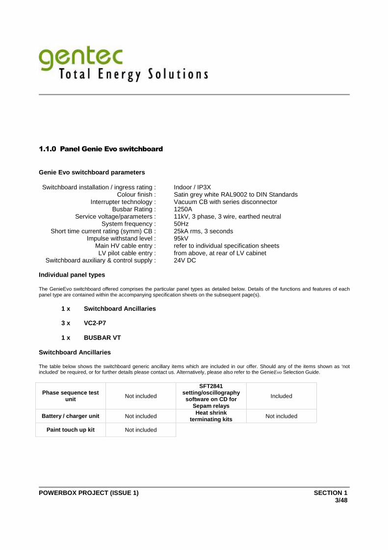
1.1.0 Panel Genie Evo switchboard
Genie Evo switchboard parameters Switchboard installation / ingress rating : Indoor / IP3X Colour finish : Satin grey white RAL9002 to DIN Standards Interrupter technology : Vacuum CB with series disconnector Busbar Rating : 1250A Service voltage/parameters : 11kV, 3 phase, 3 wire, earthed neutral System frequency : 50Hz Short time current rating (symm) CB : 25kA rms, 3 seconds Impulse withstand level : 95kV Main HV cable entry : refer to individual specification sheets LV pilot cable entry : from above, at rear of LV cabinet Switchboard auxiliary & control supply : 24V DC Individual panel types The GenieEvo switchboard offered comprises the particular panel types as detailed below. Details of the functions and features of each panel type are contained within the accompanying specification sheets on the subsequent page(s).
1 x Switchboard Ancillaries
3 x VC2-P7
1 x BUSBAR VT
Switchboard Ancillaries The table below shows the switchboard generic ancillary items which are included in our offer. Should any of the items shown as ‘not included’ be required, or for further details please contact us. Alternatively, please also refer to the GenieEvo Selection Guide.
Phase sequence test unit Not included
SFT2841 setting/oscillography software on CD for
Sepam relays
Included
Battery / charger unit Not included Heat shrink
terminating kits Not included
Paint touch up kit Not included

POWERBOX PROJECT (ISSUE 1) SECTION 1 4/48
1.1.1 VC2-P7
This panel type provides a comprehensive protection package for switchboards with one transformer incomer, or dual transformer incomers without directional overcurrent protection. It also includes monitoring of the transformer winding temperature and Buchholz devices for local and remote indication of operation. This includes extensive circuit breaker metering, monitoring and control features as standard and is ideally suited for integration into a supervisory system using its optional RS485 serial link interface.
Sepam T81 with advanced integrated UMI Protection
50/51 overcurrent – IDMT, DT (2 group settings) 50N/51N earth fault – IDMT, DT (2 group settings) 49RMS thermal overload for cables 64REF restricted earth fault
Control functions trip/close CB control trip circuit supervision (74) external protection trip remote emergency trip intertrip send/receive CB close inhibit lockout (86) logic selectivity block send/receive winding temp / buchholz
Indication / instrumentation – LED display c/w:- phase currents record of tripping currents maximum demand currents phase voltages kW, kVA, KVAR, power factor kWh, kVARh kWh pulsed output thermal capacity used
disturbance recorder – when SFT2826 software used
environment location : indoor, IP3X ambient temperature : -5 to +40oC altitude : upto 1000m above sea level
ratings short time withstand : 25kA, 3 seconds normal current rating : 200A dimensions (mm) : 1900 H x 500 W x 1200 D
operating mechanism independent manual stored energy (motorised)
test facility integral cable test and earthing (fully interlocked)
CT secondary injection test terminals (LV cabinet) circuit breaker vacuum interrupter test (fully interlocked)
standard current transformers Sepam CT’s – 200/100/1A, 2.5VA, class 5P20
cable termination main cable entry : Bottom entry connection type : direct connection to ANSI bushing cables up to 300mm² (1x3c) / up to 630mm² (3x1c)
local control and indication mechanical on/off – circuit breaker mechanical main select/isolated/earth select – series isolatormechanical operations counter circuit neon indication
circuit voltage transformer VT ratio/conn : 11kV/110V / 11kV/110V – MV fuse VT’s rating : 50VA/ph, class 0.5/3P
Optional features
Mechanism motorisation 30V DC Motor auto/off selector switch Motor On/Off Switch
Sepam RS485 serial link Not included MV cable gland(s) No gland included

POWERBOX PROJECT (ISSUE 1) SECTION 1 5/48
Prima interposing relays No Relay kit Gland plate(s) 1x3c gland plate
Control switch padlocks Not included 2 x Remote metering CT’s Not included
Key mechanical interlock Not included Control switches Trip/Neutral/Close and Local/Remote switches
included
Current transducer 4-20mA Not included Mechanism padlocks Not included
To find out more about GenieEvo range, please refer to he Selection Guide, or visit our website at : www.schneider.co.uk
2.1.2 BECB – Busbar end Cable Box
For use in applications where direct connection of an incomer or outgoing supply to the switchboard busbars is acceptable and isolation/disconnection facilities are not required.
environment location : indoor, IP3X ambient temperature : -5 to +40oC altitude : upto 1000m
ratings normal service voltage: 13.8kV
cable termination cable entry : Bottom entry cable connection type : 1 x Bushing Sleeve per phase cables up to 300mm² MV Gland(s) : Not included MV gland plate : 1x3c gland plate
To find out more about GenieEvo range, please refer to the Selection Guide, or visit our website at : www.schneider.co.uk

POWERBOX PROJECT (ISSUE 1) SECTION 1 6/48
3.1.3. BUSBAR VT
This unit type offers a busbar connected VT.
environment location : indoor, IP3X ambient temperature : -5 to +40oC altitude : upto 1000m above sea level
ratings normal rated voltage : 13.8kV dimensions (mm) : 1900 H x 500 W x 1200 D
busbar voltage transformer VT ratio/conn : 11kV/110V / Fixed – MV fuse VT rating : 50VA/ph, class 0.5/3P
To find out more about GenieEvo range, please refer to the Selection Guide, or visit our website at : www.schneider.co.uk
Support Information for Genie Evo 1.2. Description Of Genie Evo Range Panels and Switchboard Construction
Type GenieEvo, metalclad switchgear panels are of the indoor design consisting of rigid steel housings which comprise a non-withdrawable vacuum circuit breaker. The contact arrangement of the circuit breaker is of the ‘ON’ or ‘OFF’ type. The point of isolation is provided by means of a series off-load isolator within an earth screened cast resin envelope. It is not possible to switch the unit directly from ‘main’ to ‘earth’ under any circumstances. The busbar system is totally encapsulated in cast resin, terminated at each panel by means of specifically designed polyurethane shrouds. MV cable connections comprise cast resin insulated ANSI tapered bushings which provide direct and permanent connection using a heat shrink termination. Optionally, Merlin Gerin type ‘Dyscon’ disconnectable cable terminations may be employed in conjunction with the heat shrink termination, allowing the possibility of future disconnection of the MV cable without the need of breaking down the heat shrink joint.

POWERBOX PROJECT (ISSUE 1) SECTION 1 7/48
The panels are composed of the following compartments, fully segregated by steel partitions : Circuit breaker MV compartment MV cable connection compartment MV busbar compartment LV cabinet LV cable connection compartment CT compartment VT compartment Access :
⇒ All operations from unit front ⇒ LV pilot cabling, MV cable connection, and MV busbar connection from rear/side
1.3. Busbars and Connections
The busbars are manufactured from hard drawn, high conductivity copper. The contact faces are designed to ensure a reliable low resistance contact. The busbar supports are cast resin insulated and integral to the series isolator cast resin envelope. There is one busbar per phase for both 630A and 1250A current rating. Simple jointing methods are employed, incorporating a single fixing per joint to ensure minimised installation time and reliability of the installation. 1.4. Current Transformers - Circuit Connection
Current transformers are of the air insulated ring type design and are installed on cast resin insulated bar primaries within the CT compartment. The CT’s, when used in conjunction with the Merlin Gerin type Sepam protection, metering and control unit, are specifically designed to suit the needs of the Sepam device. Alternatively, for panel types utilising unit protection relays, data sheets for the standard CT’s employed can be provided upon request. 1.5. Voltage Transformers - Circuit Connection
Voltage transformers are of the single phase [live to earth connection] dry, cast resin insulated design. Where fitted, the transformers are located within the VT compartment beneath the vacuum circuit breaker. The VT’s are non-withdrawable, but can be isolated via removal of the MV fuses. 1.6. Voltage Transformers - Busbar Connection
Voltage transformers are of the single phase [live to earth connection] dry, cast resin insulated design. Busbar VT’s can be located either within a bus-section panel to the right-hand side of the circuit breaker (when provided) or within a separate, dedicated 500mm wide cubicle. The VT’s are non-withdrawable, but can be isolated via removal of the MV fuses. 1.7. Cable Earthing and Testing Facilities
The circuit connected MV cables may be earthed by means of the fully interlocked series isolator. This isolator is interlocked so that it can only be operated once the circuit breaker unit is in the ‘off’ position. The series

POWERBOX PROJECT (ISSUE 1) SECTION 1 8/48
isolator utilised on GenieEvo is unique in design, employing a controlled air environment in a fully encapsulated cast resin earth screened envelope. The ‘sealed for life’ design is impervious to the local environment ensuring that the series isolator is totally maintenance free. Cable testing is facilitated via the series isolator, following initial application of earth and subsequent operation of interlocks. With GenieEvo there is no requirement for a loose test access key. Access to the normally earthed ‘star point’ connected to the cables is at the front of the equipment. There is no requirement to enter the MV cable box during cable testing. 1.7. Busbar Earthing and Testing Facilities
When a bus-section unit is employed, the busbars to either the right-hand or left-hand side of the unit in turn may be earthed by means of the units’ fully interlocked series isolators. As a preventative method against inadvertent maloperation, key type mechanical interlocks in conjunction with wall mounting key exchange boxes are optionally available. 1.8. Low Voltage Wiring
Secondary wiring on each panel comprises our standard arrangement which utilises suitably rated PVC insulated stranded copper wire coloured ‘black’. Mains 230 volt a.c terminations will be segregated and shrouded. 1.9. Anti-Corrosion Protection and Finishing
To permit the use of GenieEvo range under onerous climatic conditions, a systematic, comprehensive finishing process is adopted. A copy of our detailed finishing specification can be made available upon request. 1.10. Labelling
The unit data label is fitted at the unit front identifying the unit serial number, panel type and ratings. Blank engravable circuit identification labels are provided at the front and rear of each panel. The styling is black lettering on a white background. Internal devices, such as VT’s and CT’s are identified by separate permanent adhesive labels located within the LV cabinet. All labels and literature will be in the English language.

POWERBOX PROJECT (ISSUE 1) SECTION 1 9/48
1.12. General Technical Data
Rated Mechanical Operations 10,000 close & open cycles - main 2,000 close & open cycles - earth
Standards IEC 60694; IEC 62271-102; IEC 62271-100; IEC 60298; IEC 61000; IEC 61958; IEC 60186; IEC 60255; EATS 41-36; EATS 50-18; EATS 12-11; BS EN ISO 9001; BS EN ISO 14001; BS 5227
1.13. Additional Related Standards
National BS 3938
Current transformers International IEC 60044-1
National BS 3941 Voltage transformers
International IEC 60044-2
National BS 142 Relays
International IEC 60255
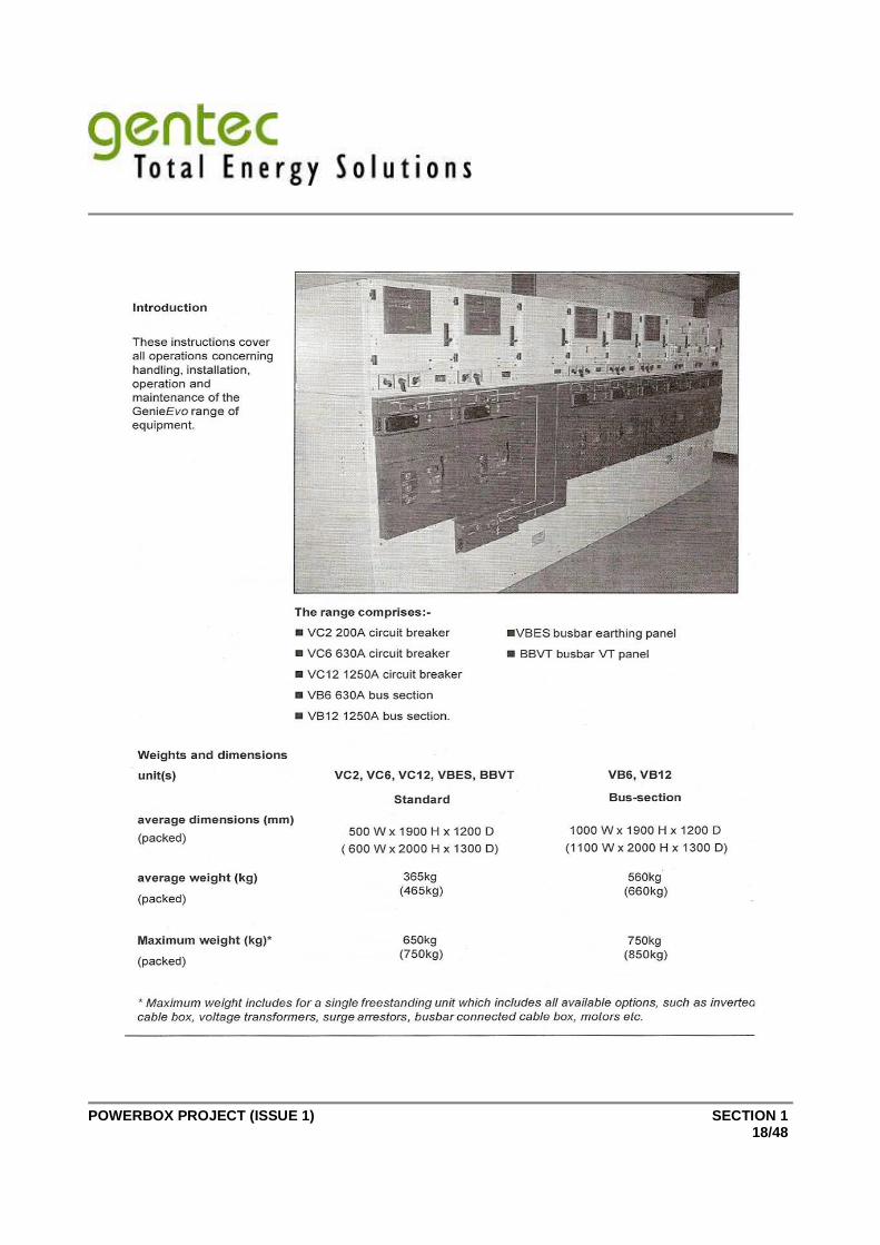
1.14. Weights and Dimensions
Dimensions
Panel Weight width height depth
Standard panels 365 kg max 500 mm 1900 mm 1200 mm
Bus-sections 560 kg max 1000 mm 1900 mm 1200 mm

POWERBOX PROJECT (ISSUE 1) SECTION 1 10/48
Support Information Sepam Series 80
1.15. Overview
Specially designed for demanding customers on large industrial sites, Sepam series 80 provides proven solutions for electrical distribution and machine protection. 1.16. Base Unit with Advanced User-Machine Interface
Sepam Series 80 base relays employed on the GenieEvo range of switchgear are provided with an integrated advanced user-machine interface to allow flush mounting of the relay on the instrument cabinet door. The interface is optimal for making local operation easier since it is easy to read and provides content and access to different data. Comprehensive data for facility managers
All the data required for local equipment operation may be displayed on demand : > Display of all measurement and diagnosis data > Display of operating and alarm messages, with alarm
acknowledgement and Sepam resetting > Display of the list of activated protection functions and the main
settings of major protection functions > Adaptation of activated protection functions set points or time delays in
response to new operating constraints > Display of Sepam and remote module versions > Relay output testing and logic input status display > Entry of 2 passwords to protect parameter and protection setting
9-key keypad > Keys identified by pictograms for intuitive navigation > Menu guided access to data Graphical LCD screen > 128 x 64 pixel graphical screen to display any character or symbol > data presentation in numerical format with units and/or in bar graphs > automatic contrast adjustment and user-triggered backlighting for easy reading in all lighting
conditions

POWERBOX PROJECT (ISSUE 1) SECTION 1 11/48
1.17. Hardware Characteristics
Removable memory cartridge
The cartridge contains all the Sepam characteristics : > all Sepam protection and parameter settings > all the metering and protection functions required for the application > pre-defined control functions > control functions customised by control matrix or logic equations > accumulated energies and switchgear diagnostic values It may be made tamper-proof by lead sealing It is removable and easy to access on the front panel of Sepam to reduce maintenance time
Backup battery Standard lithium battery, ½ AA format, 3.6 volts It allows the following data to be stored in the event of an auxiliary power outage : > time tagged event tables > disturbance recording data > peak demands, tripping context etc The battery presence and charge are monitored by Sepam. The main data (e.g., protection and parameter settings) are saved in the event of an auxiliary power outage, regardless of the state of the battery.

POWERBOX PROJECT (ISSUE 1) SECTION 1 12/48
1.18. Advanced UMI Front Panel Controls and Operation
1. Green LED ; Sepam ON 2. Red LED ; Sepam unavailable 3. 9 yellow indication LEDs 4. Label identifying the indication LEDs 5. Graphical LCD screen 6. Display of measurements 7. Display of switchgear, network and machine
diagnosis data 8. Display of alarm messages 9. Sepam reset (or confirm data entry) 10. Acknowledgement and clearing of alarms (or
move cursor up) 11. LED test (or move cursor down) 12. Display and adaptation of activated
protection settings 13. Display of Sepam and Logipam data 14. Entry of 2 passwords 15. RS 232 PC connection port 16. Backup battery 17. Memory cartridge 18. Door

POWERBOX PROJECT (ISSUE 1) SECTION 1 13/48
1.19. Electrical Characteristics
Sensor inputs Phase current inputs 1A CT Input impedance < 0.001 Ω
Consumption < 0.001 VA (1A CT)
Continuous thermal withstand 3 In
1 second overload 100 In
Voltage inputs Phase Residual Input impedance > 100kΩ > 100kΩ
Consumption < 0.015VA (100V VT) < 0.015VA (100V VT)
Continuous thermal withstand 240 V 240 V
1 second overload 480 V 480 V
Relay outputs Control relay outputs O1 to O4 Voltage DC 24/48 VDC 127 VDC 220 VDC
AC (47.5 to 63Hz) 100 to 240 VAC
Continuous current 8 A 8 A 8 A 8 A
Breaking capacity Resistive load 8 A / 4 A 0.7 A 0.3 A Load L/R < 20ms 6 A / 2 A 0.5 A 0.2 A
Load L/R < 40ms 4 A / 1 A 0.2 A 0.1 A Resistive load 8 A
Load p.f. > 0.3 5 A Making capacity < 15 A for 200ms
Annunciation relay output O5 Voltage DC 24/48 VDC 127 VDC 220 VDC
AC (47.5 to 63Hz) 100 to 240 VAC Continuous current 2 A 2 A 2 A 2 A
Breaking capacity L/R load < 20ms 2 A / 1 A 0.5 A 0.15 A Load p.f. > 0.3 1 A
Power supply Voltage 24 to 250 VDC -20% / + 10%
Maximum consumption 10 to 16 W according to configuration
Inrush current < 10 A 10 ms
Acceptable ripple content 12 %
Acceptable momentary outages 100 ms
Battery Format ½ AA lithium 3.6V
Service life 10 years Sepam energised
8 years Sepam not energised

POWERBOX PROJECT (ISSUE 1) SECTION 1 14/48
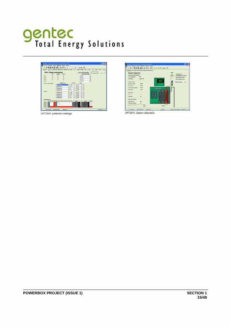
Support Information SFT2841 Setting and Operating Software
1.20. Overview
The SFT2841 software allows use of the Expert UMI functions when installed on a PC and connected to the RS 232 link on the front panel of the Sepam (operating in a Windows environment). All the data used for the same tasks are grouped together in the same screen to facilitate operation. Menus and icons are used for fast, direct access to the required information. Minimum PC configuration required : Processor PC compatible, Pentium 133 MHz Operating Systems Micorsoft Windows 98/NT4.0/2000/XP RAM 64 MB (32 MB for Windows 98) Space on disk 64 MB It may be used :
Prior to commissioning and without connection to Sepam, to prepare Sepam protection and parameter settings
During commissioning, on a PC connected to the front panel of Sepam : To load, unload and modify Sepam protection and parameter settings To obtain all measurements and useful information during commissioning
During operation, on a PC connected to a set of Sepam series 80 relays via a communication network : To manage the protection system To monitor the status of the electrical network To run diagnostics on any incidents affecting the electrical network
POWERBOX PROJECT (ISSUE 1) SECTION 1 15/48

POWERBOX PROJECT (ISSUE 1) SECTION 1 16/48

POWERBOX PROJECT (ISSUE 1) SECTION 1 17/48
POWERBOX PROJECT (ISSUE 1) SECTION 1 18/48

POWERBOX PROJECT (ISSUE 1) SECTION 1 19/48
POWERBOX PROJECT (ISSUE 1) SECTION 1 20/48
POWERBOX PROJECT (ISSUE 1) SECTION 1 21/48

POWERBOX PROJECT (ISSUE 1) SECTION 1 22/48

POWERBOX PROJECT (ISSUE 1) SECTION 1 23/48

POWERBOX PROJECT (ISSUE 1) SECTION 1 24/48

POWERBOX PROJECT (ISSUE 1) SECTION 1 25/48

POWERBOX PROJECT (ISSUE 1) SECTION 1 26/48

POWERBOX PROJECT (ISSUE 1) SECTION 1 27/48

POWERBOX PROJECT (ISSUE 1) SECTION 1 28/48

POWERBOX PROJECT (ISSUE 1) SECTION 1 29/48
POWERBOX PROJECT (ISSUE 1) SECTION 1 30/48

POWERBOX PROJECT (ISSUE 1) SECTION 1 31/48

POWERBOX PROJECT (ISSUE 1) SECTION 1 32/48

POWERBOX PROJECT (ISSUE 1) SECTION 1 33/48

POWERBOX PROJECT (ISSUE 1) SECTION 1 34/48

POWERBOX PROJECT (ISSUE 1) SECTION 1 35/48

POWERBOX PROJECT (ISSUE 1) SECTION 1 36/48

POWERBOX PROJECT (ISSUE 1) SECTION 1 37/48

POWERBOX PROJECT (ISSUE 1) SECTION 1 38/48

POWERBOX PROJECT (ISSUE 1) SECTION 1 39/48

POWERBOX PROJECT (ISSUE 1) SECTION 1 40/48

POWERBOX PROJECT (ISSUE 1) SECTION 1 41/48

POWERBOX PROJECT (ISSUE 1) SECTION 1 42/48

POWERBOX PROJECT (ISSUE 1) SECTION 1 43/48
POWERBOX PROJECT (ISSUE 1) SECTION 1 44/48

POWERBOX PROJECT (ISSUE 1) SECTION 1 45/48

POWERBOX PROJECT (ISSUE 1) SECTION 1 46/48

POWERBOX PROJECT (ISSUE 1) SECTION 1 47/48

POWERBOX PROJECT (ISSUE 1) SECTION 1 48/48