Embed Size (px)
Citation preview

SCENE COMMANDER
w w w . p r o l i g h t . c o . u k U S E R M A N U A L
O R D E R C O D E : B O T E 3 3
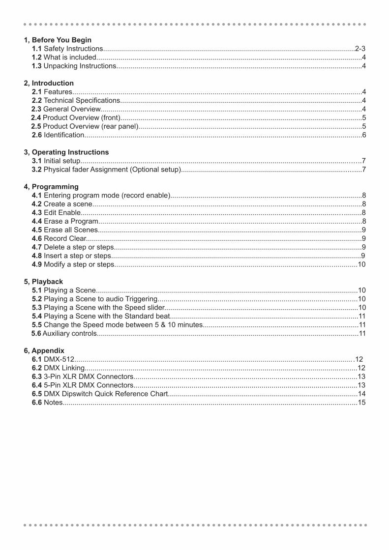
1, Before You Begin 1.1 Safety Instructions..............................................................................................................................2-3 1.2 What is included.....................................................................................................................................4 1.3 Unpacking Instructions...........................................................................................................................4
2, Introduction 2.1 Features.................................................................................................................................................4 2.2 Technical Specifications.........................................................................................................................4 2.3 General Overview...................................................................................................................................4 2.4 Product Overview (front).........................................................................................................................5 2.5 Product Overview (rear panel)................................................................................................................5 2.6 Identification...........................................................................................................................................6
3, Operating Instructions 3.1 Initial setup............................................................................................................................................7 3.2 Physical fader Assignment (Optional setup)..........................................................................................7
4, Programming 4.1 Entering program mode (record enable)................................................................................................8 4.2 Create a scene.......................................................................................................................................8 4.3 Edit Enable............................................................................................................................................8 4.4 Erase a Program....................................................................................................................................8 4.5 Erase all Scenes....................................................................................................................................9 4.6 Record Clear..........................................................................................................................................9 4.7 Delete a step or steps............................................................................................................................9 4.8 Insert a step or steps.............................................................................................................................9 4.9 Modify a step or steps.........................................................................................................................10
5, Playback 5.1 Playing a Scene...................................................................................................................................10 5.2 Playing a Scene to audio Triggering....................................................................................................10 5.3 Playing a Scene with the Speed slider.................................................................................................10 5.4 Playing a Scene with the Standard beat..............................................................................................11 5.5 Change the Speed mode between 5 & 10 minutes..............................................................................11 5.6 Auxiliary controls...................................................................................................................................11
6, Appendix 6.1 DMX-512........................................................................................................................................... .12 6.2 DMX Linking........................................................................................................................................12 6.3 3-Pin XLR DMX Connectors................................................................................................................13 6.4 5-Pin XLR DMX Connectors................................................................................................................13 6.5 DMX Dipswitch Quick Reference Chart...............................................................................................14 6.6 Notes...................................................................................................................................................15
WARNING
FOR YOUR OWN SAFETY, PLEASE READ THIS USER MANUAL CAREFULLY BEFORE YOUR INITIAL START-UP!
CAUTION!
Keep this equipment away from rain, moisture and liquids.
SAFETY INSTRUCTIONS
Every person involved with the installation, operation & maintenance of this equipment should: - Be competent - Follow the instructions of this manual
CAUTION! TAKE CARE USING THIS EQUIPMENT!HIGH VOLTAGE-RISK OF ELECTRIC SHOCK!!
Before your initial start-up, please make sure that there is no damage caused during transportation. Should there be any, consult your dealer and do not use theequipment.
To maintain the equipment in good working condition and to ensure safe operation, it is necessary for the user to follow the safety instructions and warning notes written in this manual.
Please note that damages caused by user modifications to this equipment are not subject to warranty.
2

IMPORTANT: The manufacturer will not accept liability for any resulting damages caused by the non-observance of this manual or any unauthorised modification to theequipment.
• Never let the power-cable come into contact with other cables. Handle the power-cable and all mains voltage connections with particular caution! • Never remove warning or informative labels from the equipment. • Do not open the equipment and do not modify the equipment. • Do not switch the equipment on and off in short intervals, as this will reduce the system’s life. • Only use the equipment indoors. • Do not expose to flammable sources, liquids or gases. • Always disconnect the power from the mains when equipment is not in use or before cleaning! Only handle the power-cable by the plug. Never pull out the plug by pulling the power-cable. • Make sure that the available voltage is between 220v/240v. • Make sure that the power-cable is never crimped or damaged. Check the equipment and the power-cable periodically. • If the equipment is dropped or damaged, disconnect the mains power supply immediately. Have a qualified engineer inspect the equipment before operating again. • If the equipment has been exposed to drastic temperature fluctuation (e.g. after transportation), do not switch it on immediately. The arising condensation might damage the equipment. Leave the equipment switched off until it has reached room temperature. • If your product fails to function correctly, discontinue use immediately. Pack the unit securely (preferably in the original packing material), and return it to your Prolight dealer for service. • Only use fuses of same type and rating. • Repairs, servicing and power connection must only be carried out by a qualified technician. THIS UNIT CONTAINS NO USER SERVICEABLE PARTS. • WARRANTY; One year from date of purchase.
OPERATING DETERMINATIONS
If this equipment is operated in any other way, than those described in this manual,the product may suffer damage and the warranty becomes void.
Incorrect operation may lead to danger e.g.: short-circuit, burns and electric shocks etc.
Do not endanger your own safety and the safety of others!Incorrect installation or use can cause serious damage to people and property.
3

1.2 What is included:
1) DMX-512 dimming console2) DC 9V 1000mA adaptor3) Manual4) LED goose neck lamp
1.3 Unpacking instructions:
Immediately upon receiving the fixture, carefully unpack the carton, check the contents to ensure that all parts are present, and have been received in good condition. Notify the shipper immediately and retain packing material for inspection if any parts appear damaged from shipping or the carton itself shows signs of mishandling. Save the carton and all packing materials. In the event that a fixture must be returned to the factory, it is important that the fixture be returned in the original factory carton and packing.
2. INTRODUCTION
2.1 Features
• 24 channel DMX-512 dimming console• 4 pages with 12 scenes with total 48 playback faders (simultaneous playback)• 96,000 programmable steps• 2 programmable AUX buttons• Adjustable chase and fade times• Re-assignable channels• 3 and 5-pin DMX outputs• Built-in cross fader, dark and kill buttons• Direct audio input• Sequential linking or simultaneous playback of chases• Override chases on the fly• Beat activation, tap sync and auto run• 7U Rack mountable
2.2 Technical Specifications
Maximum ambient temperature ......................................................................................................104°F (40˚)Data output .................................................................. .............................. locking 3/5pin XLR female socketData pin configuration .......................................................................................pin 1 shield, pin 2 (-), pin 3 (+)Protocols ................................................................................................ ...............................DMX-512 USITTPower supply .....................................................................................................................DC 9V 1000mA minDimensions (L x W x H)....................................................................................................... 485 x 290 x 98mmWeight.................................................................................................................................................... 5.0Kgs
2.3 General Overview This dimmer console is a universal intelligent lighting controller. lt allows the control of 24 channels with 48 scene/chase playback faders. Each scene/chase can contain up to 1000 individual steps, or looks. On the surface, when in the CHASE SCENE mode, there are 12 physical faders for the playback of the saved programs. There are 4 pages of scenes playback on page A. Programmes can be triggered by music,automatically or manually. Channel assignments can be reprogrammed for ease of controlling different fixtures. On the surface you will find various programming tools, such as 24 channel faders, A/B master faders for cross mixing and Fade and Speed time faders for on the fly adjustments. It also has an LED display for easy navigation of controls and menu functions.
4

MASTER FADE SPEED
A B
654321 7 8 9 10 11 12
BLIND HOME TAP SYNC FULL ON BLACK OUT
DOWN
DARK MODE SELECT PAGE
HOLD
INSTANT
0.2s
0.5s1s
2s
5s10s30s
1m
2m
5m10m
MINs
0.1s
0.2s
0.5s1s
2s
5s10s30s
1m
2m
5mMINs
SHOW MDOE
0.1s
0.2s
1s2s
5s
10s20s1m
2m
5m
10mMINs
SHOW MDOE
STEP
SINGLE CHASEMIX CHASE
5MIN 10MIN
PARK BPARK A AUDIO
AUDIOLEVEL
1 2 3 4
ADD/KILL RECORD
BEAT REV CHASE REV
REC SPEED
SCENESPRESET BA DOUBLE
1-24 SINGLE PRESET
CHASE
REC CLEAR REC EXIT SHIFT
REV ONE % OR 0-255 ALL REV
UP DELETE INSERT EDIT
AUX 1 AUX 2
2.4 Product Overview (front)
2.5 Product Overview (rear panel)
Note: For the Overview Identification please see page 6.
5
MASTER FADE SPEED
A B
654321 7 8 9 10 11 12
BLIND HOME TAP SYNC FULL ON BLACK OUT
DOWN
DARK MODE SELECT PAGE
HOLD
INSTANT
0.2s
0.5s1s
2s
5s10s30s
1m
2m
5m10m
MINs
0.1s
0.2s
0.5s1s
2s
5s10s30s
1m
2m
5mMINs
SHOW MDOE
0.1s
0.2s
1s2s
5s
10s20s1m
2m
5m
10mMINs
SHOW MDOE
STEP
SINGLE CHASEMIX CHASE
5MIN 10MIN
PARK BPARK A AUDIO
AUDIOLEVEL
1 2 3 4
ADD/KILL RECORD
BEAT REV CHASE REV
REC SPEED
SCENESPRESET BA DOUBLE
1-24 SINGLE PRESET
CHASE
REC CLEAR REC EXIT SHIFT
REV ONE % OR 0-255 ALL REV
UP DELETE INSERT EDIT
AUX 1 AUX 2

6
2.6 Overview Identification
Front
Number Number1 12 2
3
4
5
6
USB Lamp socket
Power on/off switch
Audio input
Remote input
DC input
3
4
5
6
7
8
9
10
12
13
14
15
17
18
22
23
24
27
293031
19
26
25
28
16
20
21
11
Button/fader Button/faderChannel faders 3/5-pin DMX socketsFlash buttons
Fader LEDs
Scene LEDs
Flash buttons
Down/Beat Rev
Up/Chase Rev
LCD display
Delete/Rev One
AUX 1
AUX 1
Edit/All Rev
Recored/Shift
Audio
Dark
Home
Hold
Page
Full on
Blackout
Speed FaderFade FaderMaster A-B
Park
Add Kill/Rec Exit
Step
Audio Level Fader
Blind
Mode Select/Rec Speed
Tap Sync
Insert % or 255
Function FunctionChannel faders 1-24 DMX output sockets
For USB Lamp
To turn the console on or off
This jack accepts a line level audio input signalranging from 100 mV to 1Vpp
Blackout and Full On may be controlled by aremote control using a standard 1/4 jack
DC 9V, 1000mA
0-100% dimming or DMX value of 255for channels 1-12
Indicates selected channel 1-24
Indicates which scene is being played back
0-100% dimming or DMX value of 255for channels 13-24
Down functions to modify a scene in edit mode.Beat Rev is used to reverse the chasing of a programme with regular beat.
Up function is to modify a scene in edit mode.Chase reverse is used to reverse the chasing direction of a programme under speed slider control.
Shows the current programming
Deletes a step in a scene or reverses the chasing direction of any programme.
Controls a channel in 1 of 2 modes of operation
Controls a channel in 1 of 2 modes of operation
Edit is used to activate Edit mode; All Rev is toreverse the chasing direction of all programmes
Record is used to activate Record mode or program astep; Shift functions the alternate function of otherbuttons only
Audio activate audio sync of a program
Used to temporarily blackout overall output
Used to deactivate the Blind on a given channel
Used the momentarily maintain current scene
Tap to select pages of scenes from 1-4(Page A)
Brings all channels (1-24) to full output
Used to kill all output, with exception of Full On
Adjusts the speed of scenes/chases running
Adjusts the fade-in,fade-out,and cross-fade times
Adjusts overall output
Used to select Single/Mix Chase, bring Channel 13-24 to full of current setting, or momentarily programa scene into Master B slider depending on thecurrent mode
In Add mode, multiple scenes or Flash buttons will beon at the same time; ln kill mode, pressing any Flashbutton will kill any other scenes or programes; Rec Exitis used to exit from Program or Edit mode
Used to go to the next step when the Speed slider is25 set in Show Mode or in Edit mode
Adjusts the audio sensitivity when in Audio triggermode of scenes
Take the channel out of a program temporarily inChase < > Scene mode
Used to activate the operating mode; Rec Speed setsthe speed of any programs chasing in Mix mode
Repeatedly tapping this button will establish thechase speed
Insert is to add 1 step/s into a scene.% or 255 is used to change the display value cycle between % and 0-255
Back
7
3. OPERATION INSTRUCTIONS
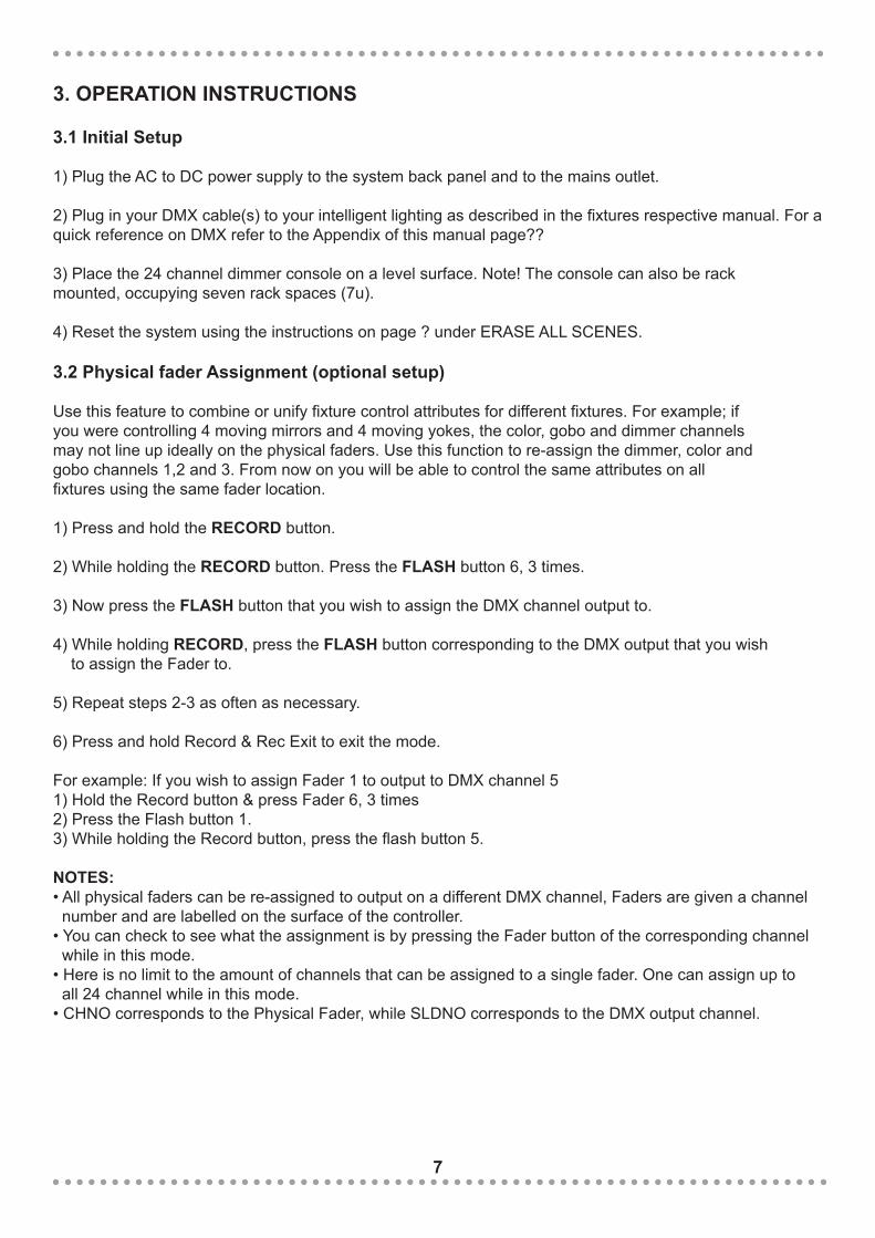
3.1 Initial Setup
1) Plug the AC to DC power supply to the system back panel and to the mains outlet.
2) Plug in your DMX cable(s) to your intelligent lighting as described in the fixtures respective manual. For a quick reference on DMX refer to the Appendix of this manual page??
3) Place the 24 channel dimmer console on a level surface. Note! The console can also be rackmounted, occupying seven rack spaces (7u).
4) Reset the system using the instructions on page ? under ERASE ALL SCENES.
3.2 Physical fader Assignment (optional setup)
Use this feature to combine or unify fixture control attributes for different fixtures. For example; ifyou were controlling 4 moving mirrors and 4 moving yokes, the color, gobo and dimmer channelsmay not line up ideally on the physical faders. Use this function to re-assign the dimmer, color andgobo channels 1,2 and 3. From now on you will be able to control the same attributes on allfixtures using the same fader location.
1) Press and hold the RECORD button.
2) While holding the RECORD button. Press the FLASH button 6, 3 times.
3) Now press the FLASH button that you wish to assign the DMX channel output to.
4) While holding RECORD, press the FLASH button corresponding to the DMX output that you wish to assign the Fader to.
5) Repeat steps 2-3 as often as necessary.
6) Press and hold Record & Rec Exit to exit the mode.
For example: If you wish to assign Fader 1 to output to DMX channel 51) Hold the Record button & press Fader 6, 3 times2) Press the Flash button 1.3) While holding the Record button, press the flash button 5.
NOTES: • All physical faders can be re-assigned to output on a different DMX channel, Faders are given a channel number and are labelled on the surface of the controller. • You can check to see what the assignment is by pressing the Fader button of the corresponding channel while in this mode.• Here is no limit to the amount of channels that can be assigned to a single fader. One can assign up to all 24 channel while in this mode.• CHNO corresponds to the Physical Fader, while SLDNO corresponds to the DMX output channel.
4. Programming
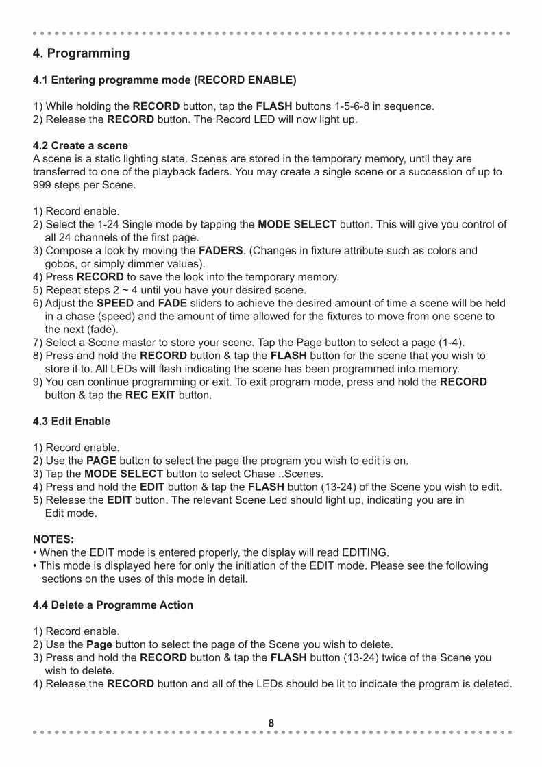
4.1 Entering programme mode (RECORD ENABLE)
1) While holding the RECORD button, tap the FLASH buttons 1-5-6-8 in sequence.2) Release the RECORD button. The Record LED will now light up.
4.2 Create a sceneA scene is a static lighting state. Scenes are stored in the temporary memory, until they aretransferred to one of the playback faders. You may create a single scene or a succession of up to 999 steps per Scene.
1) Record enable.2) Select the 1-24 Single mode by tapping the MODE SELECT button. This will give you control of all 24 channels of the first page.3) Compose a look by moving the FADERS. (Changes in fixture attribute such as colors and gobos, or simply dimmer values).4) Press RECORD to save the look into the temporary memory.5) Repeat steps 2 ~ 4 until you have your desired scene.6) Adjust the SPEED and FADE sliders to achieve the desired amount of time a scene will be held in a chase (speed) and the amount of time allowed for the fixtures to move from one scene to the next (fade).7) Select a Scene master to store your scene. Tap the Page button to select a page (1-4).8) Press and hold the RECORD button & tap the FLASH button for the scene that you wish to store it to. All LEDs will flash indicating the scene has been programmed into memory.9) You can continue programming or exit. To exit program mode, press and hold the RECORD button & tap the REC EXIT button.
4.3 Edit Enable
1) Record enable.2) Use the PAGE button to select the page the program you wish to edit is on.3) Tap the MODE SELECT button to select Chase ..Scenes.4) Press and hold the EDIT button & tap the FLASH button (13-24) of the Scene you wish to edit.5) Release the EDIT button. The relevant Scene Led should light up, indicating you are in Edit mode.
NOTES: • When the EDIT mode is entered properly, the display will read EDITING.• This mode is displayed here for only the initiation of the EDIT mode. Please see the following sections on the uses of this mode in detail.
4.4 Delete a Programme Action
1) Record enable.2) Use the Page button to select the page of the Scene you wish to delete.3) Press and hold the RECORD button & tap the FLASH button (13-24) twice of the Scene you wish to delete.4) Release the RECORD button and all of the LEDs should be lit to indicate the program is deleted.
8
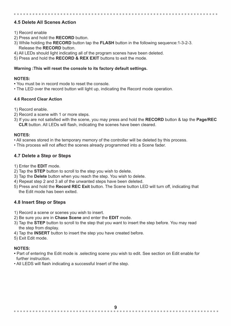
4.5 Delete All Scenes Action
1) Record enable2) Press and hold the RECORD button.3) While holding the RECORD button tap the FLASH button in the following sequence:1-3-2-3. Release the RECORD button.4) All LEDs should light indicating all of the program scenes have been deleted.5) Press and hold the RECORD & REX EXIT buttons to exit the mode.
Warning :This will reset the console to its factory default settings.
NOTES:• You must be in record mode to reset the console.• The LED over the record button will light up, indicating the Record mode operation.
4.6 Record Clear Action
1) Record enable.2) Record a scene with 1 or more steps.3) If you are not satisfied with the scene, you may press and hold the RECORD button & tap the Page/REC CLR button. All LEDs will flash, indicating the scenes have been cleared.
NOTES:• All scenes stored in the temporary memory of the controller will be deleted by this process.• This process will not affect the scenes already programmed into a Scene fader.
4.7 Delete a Step or Steps
1) Enter the EDIT mode.2) Tap the STEP button to scroll to the step you wish to delete.3) Tap the Delete button when you reach the step. You wish to delete.4) Repeat step 2 and 3 all of the unwanted steps have been deleted.5) Press and hold the Record REC Exit button. The Scene button LED will turn off, indicating that the Edit mode has been exited.
4.8 Insert Step or Steps
1) Record a scene or scenes you wish to insert.2) Be sure you are in Chase Scene and enter the EDIT mode.3) Tap the STEP button to scroll to the step that you want to insert the step before. You may read the step from display.4) Tap the INSERT button to insert the step you have created before.5) Exit Edit mode.
NOTES:• Part of entering the Edit mode is .selecting scene you wish to edit. See section on Edit enable for further instruction.• All LEDS will flash indicating a successful Insert of the step.
9
4.9 Modify a Step or Steps
1) Enter the EDIT mode.3) Tap the STEP button to scroll to the step which you want to insert the step before. You may read the step from display.4) While holding the UP or DOWN button, tap the FLASH button corresponding to the DMX channel of the Scene you wish to modify until you reach the desired intensity value read from the display. Then, you may tap the FLASH buttons until you are satisfied with the new Scene.5) Repeat step 2,3,and 4 until all the steps have been modified.6) Exit the EDIT mode.
NOTES:• Part of entering the Edit mode is selecting which scene you want to Edit. See section on enable for further instructions.• All LEDs will flash to indicate a successful insert of the step.
5. Playback
This console uses the Channel Faders and Channel Flash buttons for multiple uses. In this occurrence, Channel faders 13-24 are used playing back scenes already recorded.This is only when the controller is the Chase < > scene mode. In this instance, Master Fader A will control the manual fader controls, whish Master Fader B will control the Scenes being played back.
5.1 Playing a Scene
1) Tap the MODE SELECT button to select CHASE < > SCENE mode indicated by the red LED.2) Tap the PAGE button to select the correct page of the program you wish to run.3) Push Master Slider B to its maximum position (fully down).4) Move the desired Channel slider (13-24) to its maximum position to trigger the program, and the program will fade in depending upon current fade time. You may press and hold down the relevant FLASH button (13-24) to trigger the program.5) Move the Channel slider to adjust the output of the current program.
5.2 Playing a Scene to Music
1) Use built-in microphone or plug the audio source into the RCA Audio jack.2) Select your program as described above.3) Tap the AUDIO button until its LED lights up, indicating the Audio mode is now active.4) Use the Audio Level slider to adjust the music sensitivity.5) To return to normal mode, tap the AUDIO button a second time causing its LED to go out, the Audio mode is now disengaged.
5.3 Playing a Scene With the Speed Slider
1) Be sure the Audio mode is disengaged2) Select your program as described above.3) Move the Speed slider to the SHOW MODE position, then tap the FLASH button (13-24) while pressing and holding down the REC SPEED button, the corresponding program will not run with the Standard beat any longer.4. Now you may move the Speed Slider to select your desired speed.
NOTE:• The step 3 is not necessary if the selected program is not recorded with the Standard Beat.
10

5.4 Playing a Scene With a Standard Beat
1) Be sure the Audio is disengaged. Tap the MODE SELECT button to select CHASE < > SCENE mode.2) Tap the Park button to select Mix Chase mode, the LED lights up indicating this selection.3) Select your program as described above.4) Move the Speed slider until the Segment Display reads your desired value. You may tap the Tap Sync button twice to define your beat time.5) While pressing and holding down the REC SPEED button, tap the FLASH button (13-24) that stores the program.6) The program will then run with the set time or beat when engaged.7) Repeat steps 4 and 5 to set a new beat time.
5.5 Change the Speed mode between 5 & 10 Minutes
1) Press and hold the RECORD button.2) Tap the FLASH button 5 or 10 three times while holding down the RECORD button.3) The 5min or 10min should light up indicating the Speed slider is set to run in the 5 or 10 minute mode.
5.6 Auxiliary ControlsThis is the process of assigning the Auxiliary controls. These will act as shortcuts and are mostcommonly used for DMX strobe lights or DMX fog machines. However, they are not limited to these functions and may be used for other uses such as Pan/tilt.
1) Press & hold the RECORD button & tap the FLASH button No: 7 or No:8 three times. The display should indicate activation of the mode.2) There are 3 functions. • FUNC 1: States that the Auxiliary control is not assigned to any channel. • FUNC 2: Refers to the auxiliary controls working like the channel fader along with the flash buttons. (i.e, rotary control 0-80, flash button 81-255) • FUNC 3: Is somewhat different. The rotary knob acts to set the total output of the flash button below it. (i.e, rotary control 0-80, flash button also 0-80)3) While holding down the RECORD button, select the function you want for the auxiliary control by pressing the FLASH button 1, 2, or 3. Then release the buttons.4) To assign the auxiliary to a channel, press the FLASH button for the channel you want to assign the auxiliary control to. This sets the channel assignment. The corresponding LED above the channel will light up, indicating that the channel has ben assigned.5) Record exit.
NOTES:• You may refer to the display for the functions being edited.• Press 7 three times for AUX 1 patching, and 8 three times for AUX 2 patching.• While assigning an auxiliary to mode 2, the Fader for that channel will not function. It will act as moving the channel.• While assigning an auxiliary to mode 3, the channel fader and the auxiliary controls will both work for that channel on an HTP operating principle (highest takes precedent).
11
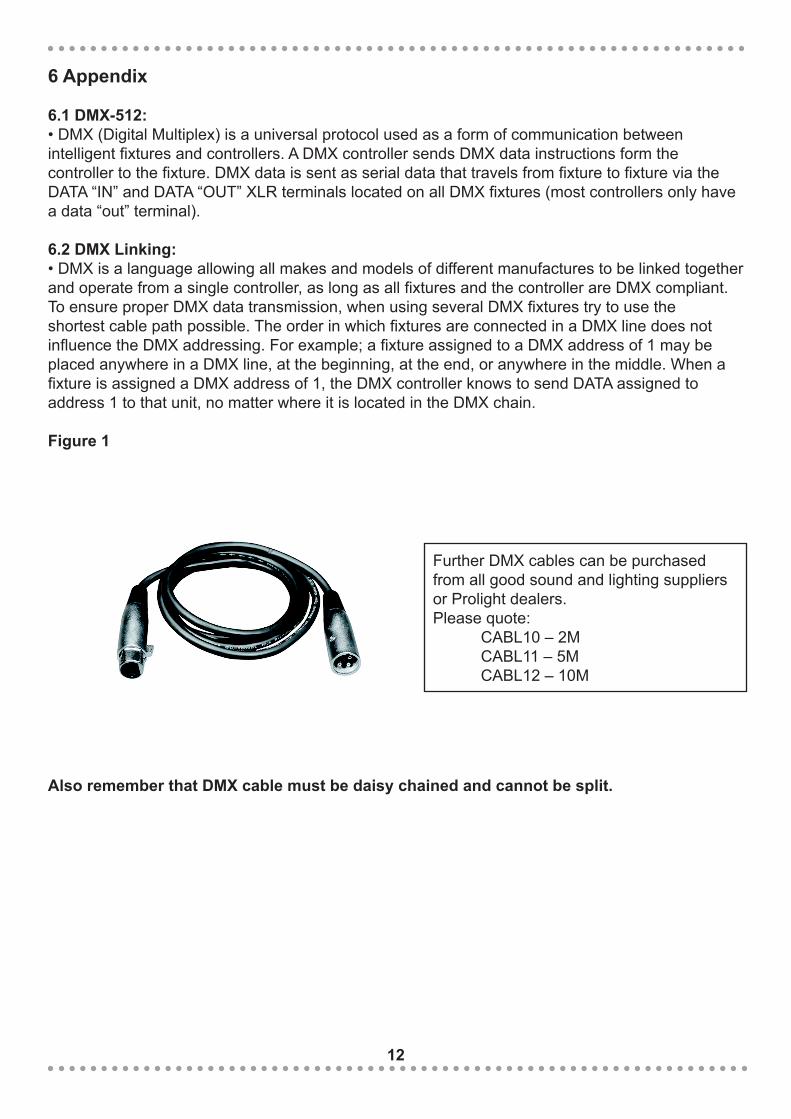
Further DMX cables can be purchased from all good sound and lighting suppliers or Prolight dealers.Please quote: CABL10 – 2M CABL11 – 5M CABL12 – 10M
6 Appendix
6.1 DMX-512: • DMX (Digital Multiplex) is a universal protocol used as a form of communication between intelligent fixtures and controllers. A DMX controller sends DMX data instructions form the controller to the fixture. DMX data is sent as serial data that travels from fixture to fixture via the DATA “IN” and DATA “OUT” XLR terminals located on all DMX fixtures (most controllers only have a data “out” terminal).
6.2 DMX Linking: • DMX is a language allowing all makes and models of different manufactures to be linked together and operate from a single controller, as long as all fixtures and the controller are DMX compliant. To ensure proper DMX data transmission, when using several DMX fixtures try to use the shortest cable path possible. The order in which fixtures are connected in a DMX line does not influence the DMX addressing. For example; a fixture assigned to a DMX address of 1 may be placed anywhere in a DMX line, at the beginning, at the end, or anywhere in the middle. When a fixture is assigned a DMX address of 1, the DMX controller knows to send DATA assigned to address 1 to that unit, no matter where it is located in the DMX chain. Figure 1
Also remember that DMX cable must be daisy chained and cannot be split.
12

6.3 5-Pin XLR DMX Connectors:
Notice: • Be sure to follow figures 2 & 3 when making your own cables. Do not connect the cable’s shield conductor to the ground lug or allow the shield conductor to come in contact with the XLR’s outer casing. Grounding the shield could cause a short circuit and erratic behaviour.
Special Note: Line termination: • When longer runs of cable are used, you may need to use a terminator on the last unit to avoid erratic behaviour.
Using a cable terminator CABL90 (3-pin) or CABL89 (5-pin) will decrease the possibilities of erratic behaviour.
6.4 5-Pin XLR DMX Connectors: • Some manufactures use 5-pin XLR connectors for data transmission in place of 3-pin. 5-Pin XLR fixtures may be implemented in a 3-pin XLR DMX line. When inserting standard 5-pin XLR connectors in to a 3-pin line a cable adaptor must be used. The chart below details the correct cable conversion.
Termination reduces signal transmission problems and interferance. it is always advisable to connect a DMX terminal, (resistance 120 Ohm 1/4 W) between pin 2 (DMX-) and pin 3 (DMX+) of the last fixture.
13

6.5 DMX Dip Switch Quick Reference Chart
Dip Switch Position
Dip Switch Position DMX ADDRESS
14
15
6.6 Notes: