Embed Size (px)
Citation preview

Industry Sector, IA&DT
SCE Training Curriculum Page 1 of 118 To be used only at Educational and R&D Facilities TIA Portal Module 090-010, Edition 03/2013 Unrestricted / © Siemens AG 2013. All Rights Reserved
SCE_EN_090-010_R1209_ WinCC Advanced with Runtime and TP700 Comfort Panel
TIA Portal Module 090-010 WinCC Advanced with Runtime and TP700 Comfort Panel
SCE Training Curriculum for
for Integrated Automation Solutions
Totally Integrated Automation (TIA) Siemens Automation Cooperates with Education

Industry Sector, IA&DT
SCE Training Curriculum Page 2 of 118 To be used only at Educational and R&D Facilities TIA Portal Module 090-010, Edition 03/2013 Unrestricted / © Siemens AG 2013. All Rights Reserved
SCE_EN_090-010_R1209_ WinCC Advanced with Runtime and TP700 Comfort Panel
Suitable SCE Trainer Packages for these training curriculums
SIMATIC controllers
SIMATIC S7-300 with CPU 314C-2PN/DP Order no.: 6ES7314-6EH04-4AB3
SIMATIC S7-300 with CPU 314C-2PN/DP (upgrade) Order no.: 6ES7314-6EH04-4AB4
SIMATIC S7-300 with CPU 315F-2PN/DP Order no.: ES7315-2FH14-4AB1
SIMATIC ET 200S with CPU IM151-8 F PN/DP Order no.: 6ES7151-8FB00-4AB1
SIMATIC HMI
SIMATIC TP700 Comfort Panel - Color Order no.: 6AV2133-4AF00-0AA0
SIMATIC STEP 7 Software for Training
SIMATIC STEP 7 Professional V11 - Single license Order no.: 6ES7822-1CC01-4YA5
SIMATIC STEP 7 Professional V11 - Classroom license (up to 12 users) Order no.: 6ES7822-1AA01-4YA5
SIMATIC STEP 7 Professional V11 - Upgrade license (up to 12 users) Order no.: 6ES7822-1AA01-4YE5
SIMATIC STEP 7 Professional V11 - Student license (up to 20 users) Order no.: 6ES7822-1AC01-4YA5
Please note that these training packages are replaced with successor packages when necessary. An overview of the currently available SCE packages is provided under: HUsiemens.com/sce/tp UH
Advanced Training For regional Siemens SCE advanced training courses, please get in touch with your regional SCE contact person siemens.com/sce/contact
Additional information regarding SCE siemens.com/sce
Information regarding usage
This SCE training curriculum for the end-to-end automation solution Totally Integrated Automation (TIA) was prepared for the program "Siemens Automation Cooperates with Education (SCE)" specifically for training purposes for public educational facilities and R&D facilities. Siemens AG does not guarantee the contents. This document curriculum is to be used only for initial training on Siemens products/systems; i.e., it can be copied entirely or partially and given to those being trained for usage within the scope of their training. Distributing or copying this training curriculum and sharing its contents is permitted within public training and advanced training facilities for training purposes. Exceptions require written permission from the Siemens AG contact person: Roland Scheuerer [email protected]. Offenders will be held liable. All rights including translation are reserved, particularly if a patent is granted or a utility model or design is registered. Usage for industrial customer courses is expressly prohibited. We do not consent to the training curriculums being used commercially. We wish to thank the Michael Dziallas Engineering Corporation and all other involved persons for their support during the preparation of this document.
Industry Sector, IA&DT
SCE Training Curriculum Page 3 of 118 To be used only at Educational and R&D Facilities TIA Portal Module 090-010, Edition 03/2013 Unrestricted / © Siemens AG 2013. All Rights Reserved
SCE_EN_090-010_R1209_ WinCC Advanced with Runtime and TP700 Comfort Panel
SEITE:
1. Preface.......................................................................................................................................................... 5
2. Notes on programming for SIMATIC S7-300 ................................................................................................ 7
2.1 SIMATIC S7-300 automation system ......................................................................................................... 7
2.2 STEP 7 Professional V11 (TIA Portal V11) programming software ........................................................... 7
2.3 Operator control and monitoring with WinCC ............................................................................................. 8
3.0 Project description ........................................................................................................................................ 9
3.1 Hardware configuration ............................................................................................................................... 9
3.2 Plant description ....................................................................................................................................... 10
3.3 Task .......................................................................................................................................................... 11
3.4 Configuration ............................................................................................................................................ 11
4. Inserting a TP700 Comfort Panel into the color mixing station project ....................................................... 12
4.1 Loading and re-saving a project template ................................................................................................ 13
5. WinCC user interface ................................................................................................................................. 25
5.1 Project tree ............................................................................................................................................... 26
5.2 Menu bar and buttons ............................................................................................................................... 26
5.3 Working area ............................................................................................................................................ 27
5.4 Tools ......................................................................................................................................................... 27
5.5 Properties window .................................................................................................................................... 28
5.6 Details view ............................................................................................................................................... 28
5.7 Layout ....................................................................................................................................................... 29
6. Device configuration of the TP700 Comfort Panel...................................................................................... 30
6.1 Setting the IP address .............................................................................................................................. 31
6.2 Setting the panel as PROFINET IO device............................................................................................... 32
7. Configuring screens .................................................................................................................................... 33
7.1 Root screen .............................................................................................................................................. 34
7.2 Tank 1 screen ........................................................................................................................................... 44
7.3 Tank 2 screen ........................................................................................................................................... 47
7.4 Tank 3 screen ........................................................................................................................................... 47
7.5 Testing configuration in Runtime .............................................................................................................. 48
8. Settings on the TP700 Comfort Touch Panel ............................................................................................. 50
8.1 Setting the date and time .......................................................................................................................... 51
8.2 Setting transfer properties ........................................................................................................................ 52
8.3 Assigning PROFINET device names ........................................................................................................ 53
8.4 Reboot ...................................................................................................................................................... 53
8.5 Transfer mode .......................................................................................................................................... 54
8.6 Configuring a connection .......................................................................................................................... 55
9. Display and operating objects ..................................................................................................................... 56
9.1 Layers ....................................................................................................................................................... 56
9.2 Basic objects............................................................................................................................................. 57
9.3 Enhanced objects ..................................................................................................................................... 59
10. Display and operating objects in the "Color mixing station" project ............................................................ 60
10.1. Configuring display and operating objects in the “Tank 1” screen ............................................................ 60
Industry Sector, IA&DT
SCE Training Curriculum Page 4 of 118 To be used only at Educational and R&D Facilities TIA Portal Module 090-010, Edition 03/2013 Unrestricted / © Siemens AG 2013. All Rights Reserved
SCE_EN_090-010_R1209_ WinCC Advanced with Runtime and TP700 Comfort Panel
10.2 Configuring display and operating objects in the “Tank 2” and “Tank 3” screens .................................... 76
10.3 Objects in the root screen ......................................................................................................................... 78
10.4 Configuring objects in the permanent window .......................................................................................... 97
11. Configuring alarms .................................................................................................................................... 101
11.1 Analog alarms ......................................................................................................................................... 101
11.2 Alarm window ......................................................................................................................................... 103
11.3 Testing alarm configuration in Runtime .................................................................................................. 104
12. Configuring recipes ................................................................................................................................... 105
12.1 Adding recipes ........................................................................................................................................ 105
12.2 Specifying data records .......................................................................................................................... 106
12.3 Creating "Recipe input" and "Select recipe" screens .............................................................................. 106
12.4 Selecting a recipe in Runtime ................................................................................................................. 111
12.5 Entering new recipes in Runtime ............................................................................................................ 112
13. Configuring user administration ................................................................................................................ 113
13.1 Setting up user groups ............................................................................................................................ 113
13.2 Creating users ........................................................................................................................................ 114
13.3 Assigning authorizations ......................................................................................................................... 115
13.4 Testing user administration in Runtime .................................................................................................. 118
Industry Sector, IA&DT
SCE Training Curriculum Page 5 of 118 To be used only at Educational and R&D Facilities TIA Portal Module 090-010, Edition 03/2013 Unrestricted / © Siemens AG 2013. All Rights Reserved
SCE_EN_090-010_R1209_ WinCC Advanced with Runtime and TP700 Comfort Panel
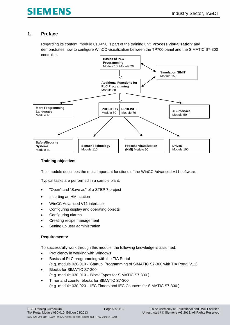
1. Preface
Regarding its content, module 010-090 is part of the training unit 'Process visualization' and
demonstrates how to configure WinCC visualization between the TP700 panel and the SIMATIC S7-300
controller.
Training objective:
This module describes the most important functions of the WinCC Advanced V11 software. Typical tasks are performed in a sample plant.
"Open" and "Save as" of a STEP 7 project
Inserting an HMI station
WinCC Advanced V11 interface
Configuring display and operating objects
Configuring alarms
Creating recipe management
Setting up user administration
Requirements:
To successfully work through this module, the following knowledge is assumed:
Proficiency in working with Windows
Basics of PLC programming with the TIA Portal
(e.g. module 020-010 - ‘Startup’ Programming of SIMATIC S7-300 with TIA Portal V11)
Blocks for SIMATIC S7-300
(e.g. module 030-010 – Block Types for SIMATIC S7-300 )
Timer and counter blocks for SIMATIC S7-300
(e.g. module 030-020 – IEC Timers and IEC Counters for SIMATIC S7-300 )
Additional Functions for
PLC Programming Module 30
Basics of PLC
Programming Module 10, Module 20
PROFIBUS PROFINET Module 60 Module 70
AS-Interface Module 50
Safety/Security
Systems Module 80
Drives Module 100
Process Visualization
(HMI) Module 90
Sensor Technology Module 110
Simulation SIMIT Module 150
More Programming
Languages Module 40
Industry Sector, IA&DT
SCE Training Curriculum Page 6 of 118 To be used only at Educational and R&D Facilities TIA Portal Module 090-010, Edition 03/2013 Unrestricted / © Siemens AG 2013. All Rights Reserved
SCE_EN_090-010_R1209_ WinCC Advanced with Runtime and TP700 Comfort Panel
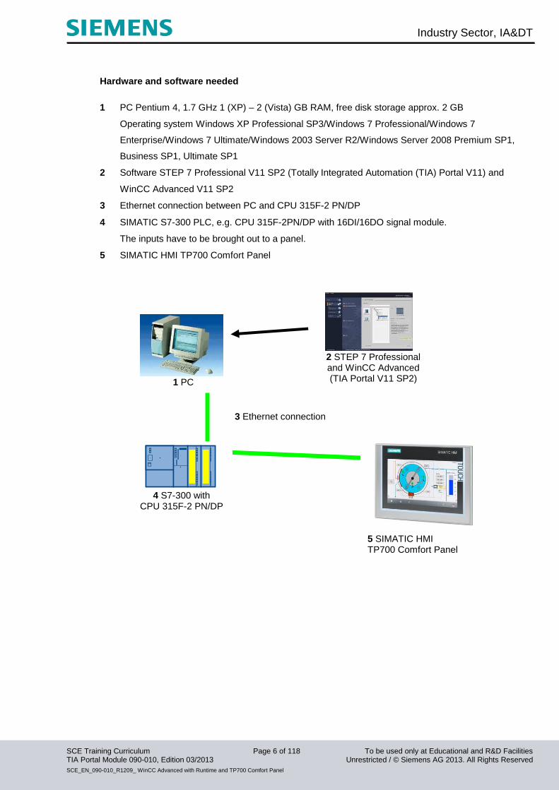
Hardware and software needed
1 PC Pentium 4, 1.7 GHz 1 (XP) – 2 (Vista) GB RAM, free disk storage approx. 2 GB
Operating system Windows XP Professional SP3/Windows 7 Professional/Windows 7
Enterprise/Windows 7 Ultimate/Windows 2003 Server R2/Windows Server 2008 Premium SP1,
Business SP1, Ultimate SP1
2 Software STEP 7 Professional V11 SP2 (Totally Integrated Automation (TIA) Portal V11) and
WinCC Advanced V11 SP2
3 Ethernet connection between PC and CPU 315F-2 PN/DP
4 SIMATIC S7-300 PLC, e.g. CPU 315F-2PN/DP with 16DI/16DO signal module.
The inputs have to be brought out to a panel.
5 SIMATIC HMI TP700 Comfort Panel
1 PC
2 STEP 7 Professional and WinCC Advanced (TIA Portal V11 SP2)
3 Ethernet connection
5 SIMATIC HMI TP700 Comfort Panel
4 S7-300 with
CPU 315F-2 PN/DP

Industry Sector, IA&DT
SCE Training Curriculum Page 7 of 118 To be used only at Educational and R&D Facilities TIA Portal Module 090-010, Edition 03/2013 Unrestricted / © Siemens AG 2013. All Rights Reserved
SCE_EN_090-010_R1209_ WinCC Advanced with Runtime and TP700 Comfort Panel
2. Notes on programming for SIMATIC S7-300
2.1 SIMATIC S7-300 automation system
The SIMATIC S7-300 automation system is a modular microcontroller system for the low and medium
performance range.
A comprehensive range of modules is available to optimally adapt the system to the automation task.
The S7 controller consists of a power supply, a CPU, and input and output modules for digital and
analog signals.
If necessary, communication processors and function modules are also used for special tasks such as
stepper motor control.
The programmable logic controller (PLC) uses the S7 program to monitor and control a machine or a
process. The I/O modules are queried via the input addresses (%I) and addressed via the output
addresses (%Q) in the S7 program.
The system is programmed with the STEP 7 software.
2.2 STEP 7 Professional V11 (TIA Portal V11) programming software
STEP 7 Professional V11 (TIA Portal V11) software is the programming tool for the following automation
systems
- SIMATIC S7-1200
- SIMATIC S7-300
- SIMATIC S7-400
- SIMATIC WinAC
STEP 7 Professional V11 provides the following functions for plant automation:
- Configuration and parameter assignment of the hardware
- Specification of the communication
- Programming
- Testing, commissioning, and servicing with operational/diagnostic functions
- Documentation
- Creation of visualizations for SIMATIC Basic Panels using the integrated WinCC Basic software.
- Visualization solutions for PCs and other panels can also be created with other WinCC software
packages
Support is provided for all functions in a comprehensive online help system.
Industry Sector, IA&DT
SCE Training Curriculum Page 8 of 118 To be used only at Educational and R&D Facilities TIA Portal Module 090-010, Edition 03/2013 Unrestricted / © Siemens AG 2013. All Rights Reserved
SCE_EN_090-010_R1209_ WinCC Advanced with Runtime and TP700 Comfort Panel
2.3 Operator control and monitoring with WinCC
System description
Since processes are becoming more and more multi-layered and the demands regarding the
functionality of machines and plants are rising, the operator needs a powerful tool to control and monitor
production systems. An HMI (Human Machine Interface) system represents the interface between the
human being (operator) and the process (machine/system). The controller has the actual control over
the process. There is an interface between the operator and WinCC (at the HMI panel) and an interface
between WinCC and the controller.
WinCC is the software that you use to handle all necessary configuration tasks. WinCC Advanced V11 is
the software for process visualization.
WinCC handles the following tasks:
• Representing the process
The process is represented on the HMI device. If, for example, a state changes in the process, the
display is updated on the HMI device.
• Operating the process
The operator can operate the process via the graphical user interface. The operator can, for example,
enter a setpoint for the controller or start a motor.
• Generating alarms
If critical process states occur in the process, an alarm is triggered automatically; for example, if a
specified limit is exceeded.
• Logging process values and alarms
The HMI system is able to log alarms and process values. Thus, the process can be documented and
you can still access older production data at a later time.
• Documenting process values and alarms
Alarms and process values can be read out by the HMI system as a log. For example, you can output
the production data at the end of a shift.
• Managing process parameters and machine parameters
The HMI system is able to store parameters for processes and machines in recipes. You can transfer
these parameters from the HMI panel to the controller, for example, in a single step in order to change
production to another product type.
Industry Sector, IA&DT
SCE Training Curriculum Page 9 of 118 To be used only at Educational and R&D Facilities TIA Portal Module 090-010, Edition 03/2013 Unrestricted / © Siemens AG 2013. All Rights Reserved
SCE_EN_090-010_R1209_ WinCC Advanced with Runtime and TP700 Comfort Panel
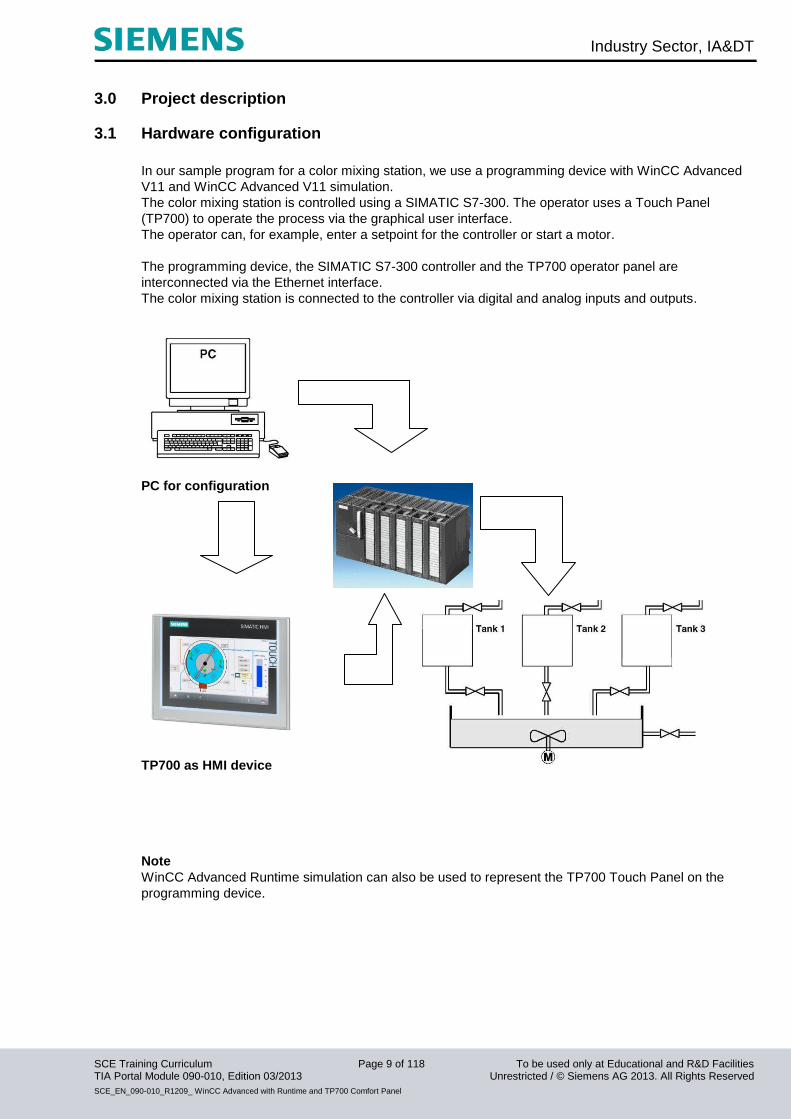
3.0 Project description
3.1 Hardware configuration
In our sample program for a color mixing station, we use a programming device with WinCC Advanced
V11 and WinCC Advanced V11 simulation.
The color mixing station is controlled using a SIMATIC S7-300. The operator uses a Touch Panel
(TP700) to operate the process via the graphical user interface.
The operator can, for example, enter a setpoint for the controller or start a motor.
The programming device, the SIMATIC S7-300 controller and the TP700 operator panel are
interconnected via the Ethernet interface.
The color mixing station is connected to the controller via digital and analog inputs and outputs.
PC for configuration
TP700 as HMI device
Note
WinCC Advanced Runtime simulation can also be used to represent the TP700 Touch Panel on the
programming device.
Industry Sector, IA&DT
SCE Training Curriculum Page 10 of 118 To be used only at Educational and R&D Facilities TIA Portal Module 090-010, Edition 03/2013 Unrestricted / © Siemens AG 2013. All Rights Reserved
SCE_EN_090-010_R1209_ WinCC Advanced with Runtime and TP700 Comfort Panel
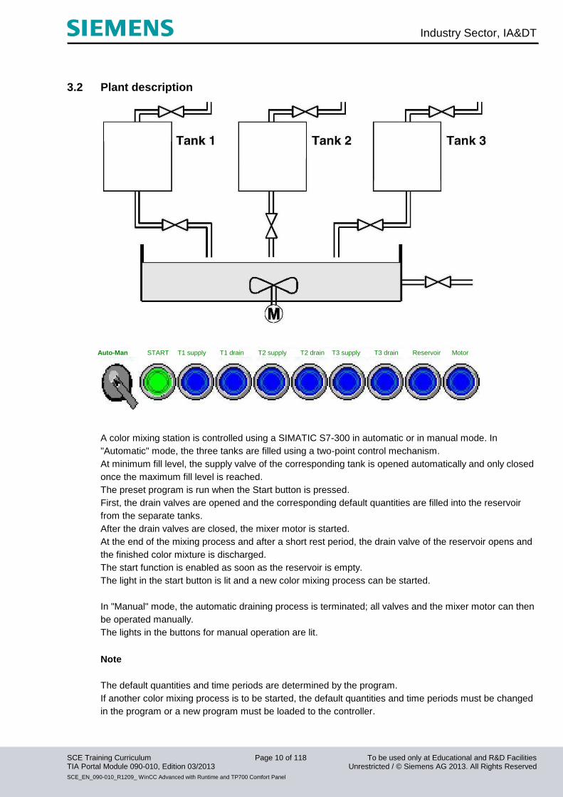
3.2 Plant description
A color mixing station is controlled using a SIMATIC S7-300 in automatic or in manual mode. In
"Automatic" mode, the three tanks are filled using a two-point control mechanism.
At minimum fill level, the supply valve of the corresponding tank is opened automatically and only closed
once the maximum fill level is reached.
The preset program is run when the Start button is pressed.
First, the drain valves are opened and the corresponding default quantities are filled into the reservoir
from the separate tanks.
After the drain valves are closed, the mixer motor is started.
At the end of the mixing process and after a short rest period, the drain valve of the reservoir opens and
the finished color mixture is discharged.
The start function is enabled as soon as the reservoir is empty.
The light in the start button is lit and a new color mixing process can be started.
In "Manual" mode, the automatic draining process is terminated; all valves and the mixer motor can then
be operated manually.
The lights in the buttons for manual operation are lit.
Note
The default quantities and time periods are determined by the program.
If another color mixing process is to be started, the default quantities and time periods must be changed
in the program or a new program must be loaded to the controller.
Auto-Man START T1 supply T1 drain T2 supply T2 drain T3 supply T3 drain Reservoir Motor
Industry Sector, IA&DT
SCE Training Curriculum Page 11 of 118 To be used only at Educational and R&D Facilities TIA Portal Module 090-010, Edition 03/2013 Unrestricted / © Siemens AG 2013. All Rights Reserved
SCE_EN_090-010_R1209_ WinCC Advanced with Runtime and TP700 Comfort Panel
3.3 Task
In the case of the color mixing station, the program was modified using the programming device every
time the mixing ratio had to be changed. Since these modifications are not only time-consuming but also
risky if input is incorrect, the decision was made to add a TP700 Comfort Touch Panel to the color
mixing station.
Using the panel, the following requirements are to be met: - It should now be possible to operate the color mixing station via the panel as well.
- The fill levels of the tanks and of the reservoir are to be indicated as bars and also as numerical
values.
- The movement of the mixer motor is to be represented graphically.
- The default quantities are to be entered using the panel.
- The minimum and maximum fill levels of the three tanks are to be displayed on separate tank
screens.
- Switching between the operating modes is also to be performed using the panel, and the respective
operating mode will be displayed on the panel.
- The finished mixtures are to be stored as recipes in the panel and need only be selected by the
operator.
- The fill levels are monitored and alarms are to be generated in the event of danger.
- A password must be entered in order to operate the color mixing station.
- Communication of the TP700 Comfort Panel with SIMATIC S7-300 controller is to take place via the
Ethernet interface.
3.4 Configuration
The STEP 7 Professional V11 configuration software and WinCC Advanced V11 are used to create a
process visualization for the color mixing station on the programming device. The process values are
represented with screens and screen objects. Default values can be transferred to the controller using
operator controls. Communication between the HMI panel and the machine or the process takes place
by means of tags via the controller. The value of a tag is written to a memory area (address) in the
controller, where it is read by the HMI panel.
The process visualization is saved and transferred from the programming device to the TP700
Comfort HMI panel after generation.
After the panel is powered up, the process can be monitored and the plant can be operated.
Industry Sector, IA&DT
SCE Training Curriculum Page 12 of 118 To be used only at Educational and R&D Facilities TIA Portal Module 090-010, Edition 03/2013 Unrestricted / © Siemens AG 2013. All Rights Reserved
SCE_EN_090-010_R1209_ WinCC Advanced with Runtime and TP700 Comfort Panel
4. Inserting a TP700 Comfort Panel into the color mixing station project
The 'Totally Integrated Automation Portal V11' software is used for project management and
programming.
Components such as control, visualization, and networking of the automation solution are created,
assigned parameters, and programmed here using a standard interface.
Online tools are available for the error diagnostics.
In the following section, a project is to be opened for SIMATIC S7-300, the project is to be stored under
a different name and adapted to the new requirements:
The central tool is the ‘TIA Portal V11’, which is opened with a double-click.
Industry Sector, IA&DT
SCE Training Curriculum Page 13 of 118 To be used only at Educational and R&D Facilities TIA Portal Module 090-010, Edition 03/2013 Unrestricted / © Siemens AG 2013. All Rights Reserved
SCE_EN_090-010_R1209_ WinCC Advanced with Runtime and TP700 Comfort Panel
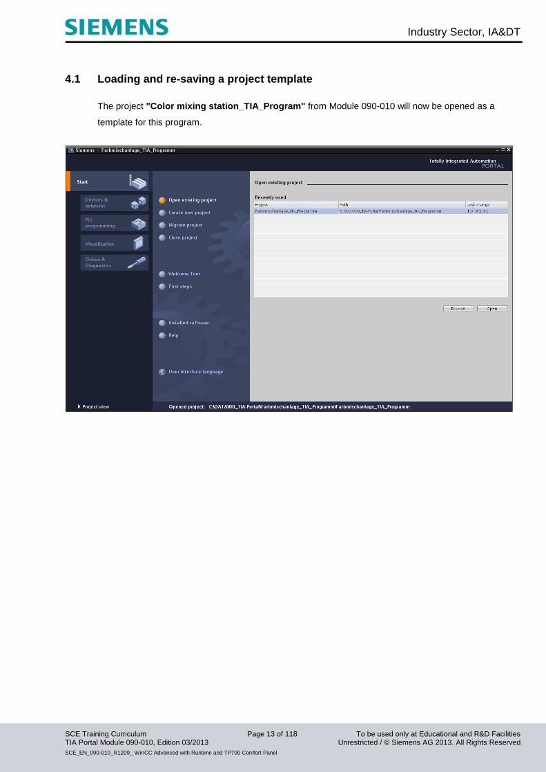
4.1 Loading and re-saving a project template
The project "Color mixing station_TIA_Program" from Module 090-010 will now be opened as a
template for this program.
Industry Sector, IA&DT
SCE Training Curriculum Page 14 of 118 To be used only at Educational and R&D Facilities TIA Portal Module 090-010, Edition 03/2013 Unrestricted / © Siemens AG 2013. All Rights Reserved
SCE_EN_090-010_R1209_ WinCC Advanced with Runtime and TP700 Comfort Panel
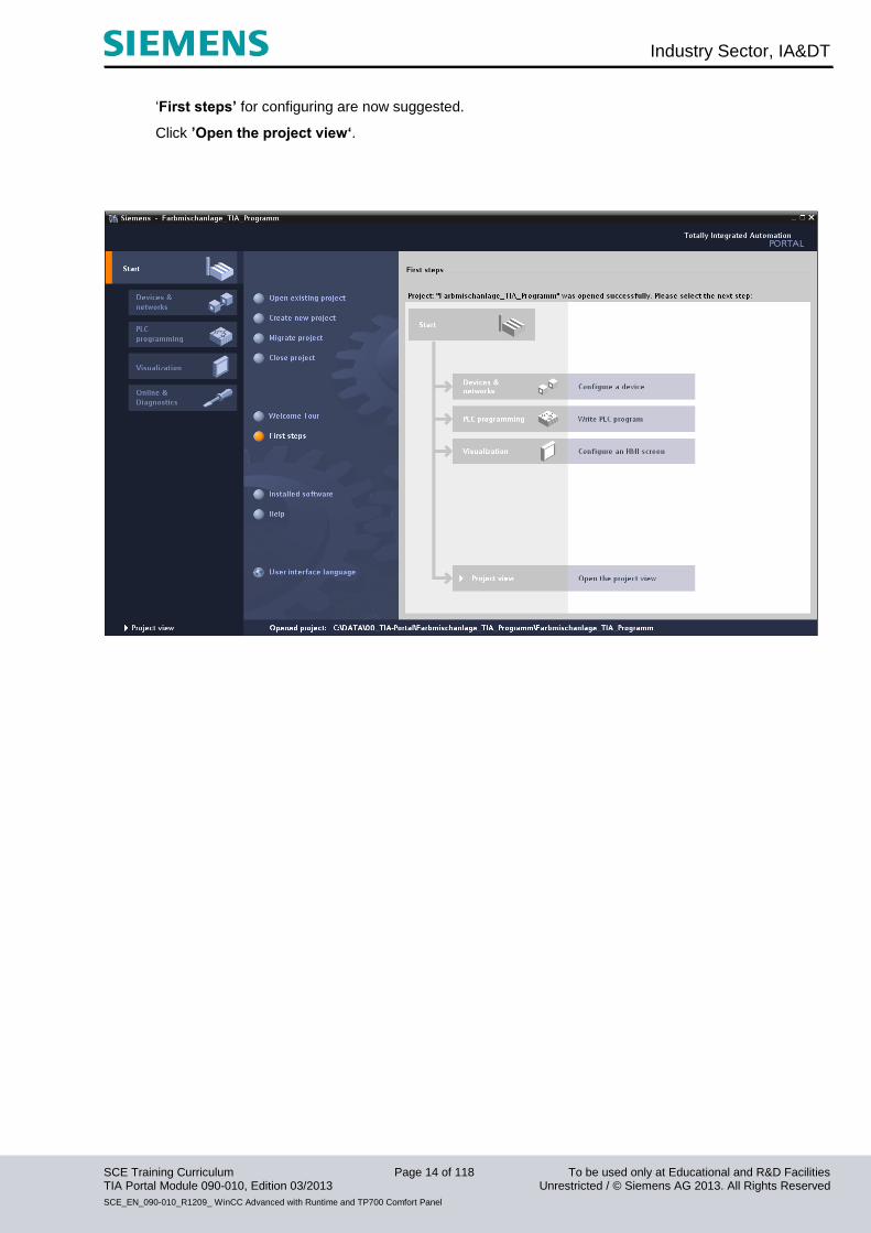
‘First steps’ for configuring are now suggested.
Click ’Open the project view‘.

Industry Sector, IA&DT
SCE Training Curriculum Page 15 of 118 To be used only at Educational and R&D Facilities TIA Portal Module 090-010, Edition 03/2013 Unrestricted / © Siemens AG 2013. All Rights Reserved
SCE_EN_090-010_R1209_ WinCC Advanced with Runtime and TP700 Comfort Panel
Start by saving the project under a different name.
In the Project menu, click "Save as".

Industry Sector, IA&DT
SCE Training Curriculum Page 16 of 118 To be used only at Educational and R&D Facilities TIA Portal Module 090-010, Edition 03/2013 Unrestricted / © Siemens AG 2013. All Rights Reserved
SCE_EN_090-010_R1209_ WinCC Advanced with Runtime and TP700 Comfort Panel
‘Save’ the project under the new name ‘Color mixing station_TIA_TP700’.
Industry Sector, IA&DT
SCE Training Curriculum Page 17 of 118 To be used only at Educational and R&D Facilities TIA Portal Module 090-010, Edition 03/2013 Unrestricted / © Siemens AG 2013. All Rights Reserved
SCE_EN_090-010_R1209_ WinCC Advanced with Runtime and TP700 Comfort Panel
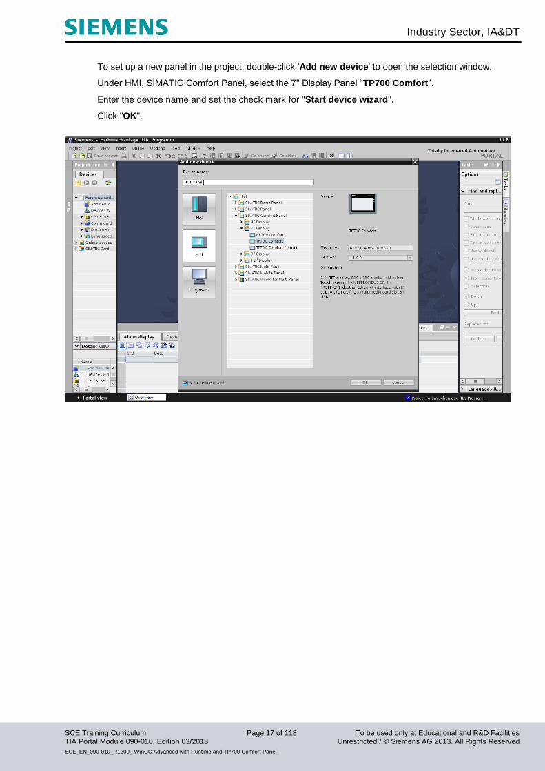
To set up a new panel in the project, double-click 'Add new device' to open the selection window.
Under HMI, SIMATIC Comfort Panel, select the 7" Display Panel “TP700 Comfort”.
Enter the device name and set the check mark for "Start device wizard".
Click "OK".

Industry Sector, IA&DT
SCE Training Curriculum Page 18 of 118 To be used only at Educational and R&D Facilities TIA Portal Module 090-010, Edition 03/2013 Unrestricted / © Siemens AG 2013. All Rights Reserved
SCE_EN_090-010_R1209_ WinCC Advanced with Runtime and TP700 Comfort Panel
Under PLC, first select the "CPU 315F-2 PN/DP".
Then, click "Next".
Industry Sector, IA&DT
SCE Training Curriculum Page 19 of 118 To be used only at Educational and R&D Facilities TIA Portal Module 090-010, Edition 03/2013 Unrestricted / © Siemens AG 2013. All Rights Reserved
SCE_EN_090-010_R1209_ WinCC Advanced with Runtime and TP700 Comfort Panel
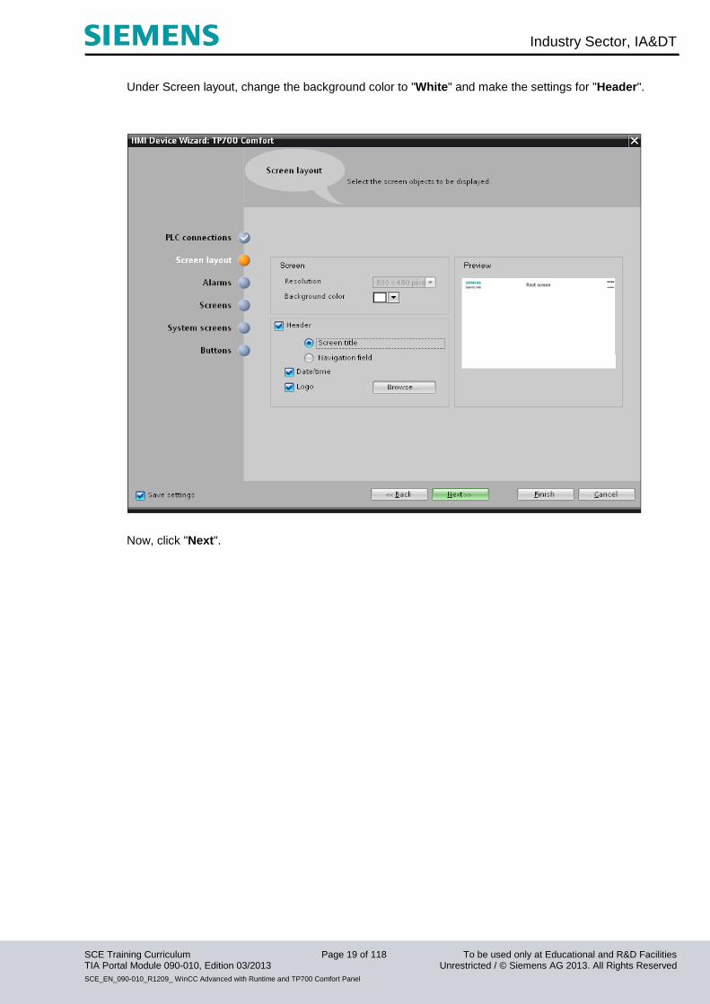
Under Screen layout, change the background color to "White" and make the settings for "Header".
Now, click "Next".
Industry Sector, IA&DT
SCE Training Curriculum Page 20 of 118 To be used only at Educational and R&D Facilities TIA Portal Module 090-010, Edition 03/2013 Unrestricted / © Siemens AG 2013. All Rights Reserved
SCE_EN_090-010_R1209_ WinCC Advanced with Runtime and TP700 Comfort Panel
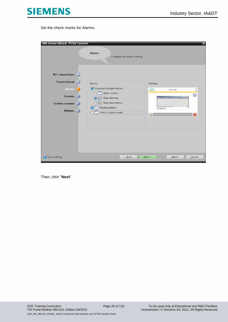
Set the check marks for Alarms.
Then, click "Next".
Industry Sector, IA&DT
SCE Training Curriculum Page 21 of 118 To be used only at Educational and R&D Facilities TIA Portal Module 090-010, Edition 03/2013 Unrestricted / © Siemens AG 2013. All Rights Reserved
SCE_EN_090-010_R1209_ WinCC Advanced with Runtime and TP700 Comfort Panel
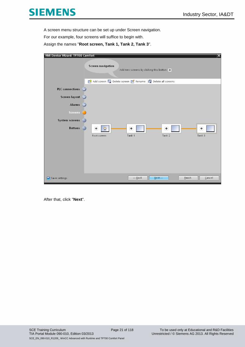
A screen menu structure can be set up under Screen navigation.
For our example, four screens will suffice to begin with.
Assign the names "Root screen, Tank 1, Tank 2, Tank 3".
After that, click "Next".
Industry Sector, IA&DT
SCE Training Curriculum Page 22 of 118 To be used only at Educational and R&D Facilities TIA Portal Module 090-010, Edition 03/2013 Unrestricted / © Siemens AG 2013. All Rights Reserved
SCE_EN_090-010_R1209_ WinCC Advanced with Runtime and TP700 Comfort Panel
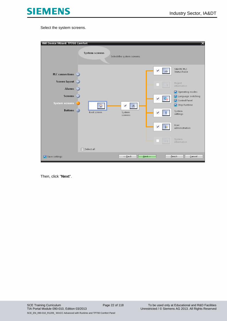
Select the system screens.
Then, click "Next".
Industry Sector, IA&DT
SCE Training Curriculum Page 23 of 118 To be used only at Educational and R&D Facilities TIA Portal Module 090-010, Edition 03/2013 Unrestricted / © Siemens AG 2013. All Rights Reserved
SCE_EN_090-010_R1209_ WinCC Advanced with Runtime and TP700 Comfort Panel
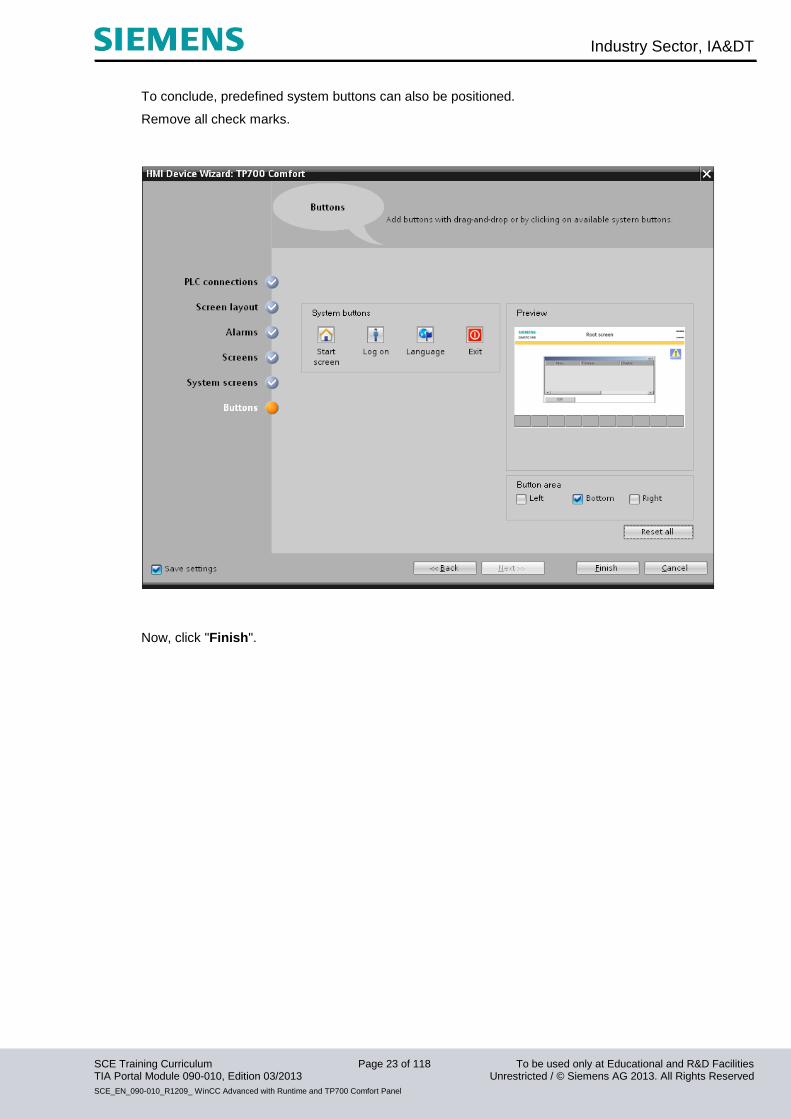
To conclude, predefined system buttons can also be positioned.
Remove all check marks.
Now, click "Finish".
Industry Sector, IA&DT
SCE Training Curriculum Page 24 of 118 To be used only at Educational and R&D Facilities TIA Portal Module 090-010, Edition 03/2013 Unrestricted / © Siemens AG 2013. All Rights Reserved
SCE_EN_090-010_R1209_ WinCC Advanced with Runtime and TP700 Comfort Panel
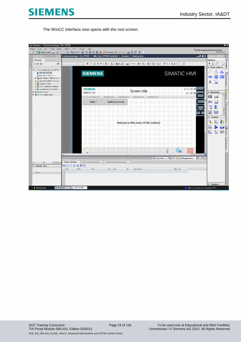
The WinCC interface now opens with the root screen.
Industry Sector, IA&DT
SCE Training Curriculum Page 25 of 118 To be used only at Educational and R&D Facilities TIA Portal Module 090-010, Edition 03/2013 Unrestricted / © Siemens AG 2013. All Rights Reserved
SCE_EN_090-010_R1209_ WinCC Advanced with Runtime and TP700 Comfort Panel
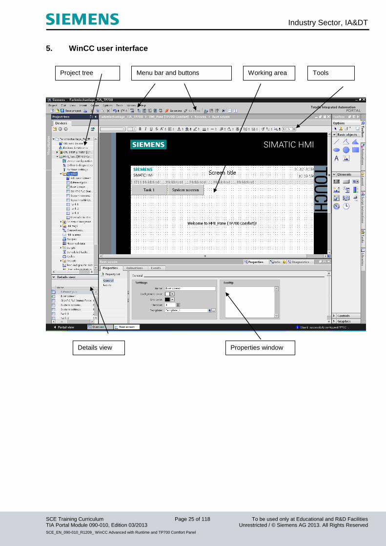
5. WinCC user interface
Project tree Menu bar and buttons
Details view Properties window
Tools Working area
Industry Sector, IA&DT
SCE Training Curriculum Page 26 of 118 To be used only at Educational and R&D Facilities TIA Portal Module 090-010, Edition 03/2013 Unrestricted / © Siemens AG 2013. All Rights Reserved
SCE_EN_090-010_R1209_ WinCC Advanced with Runtime and TP700 Comfort Panel
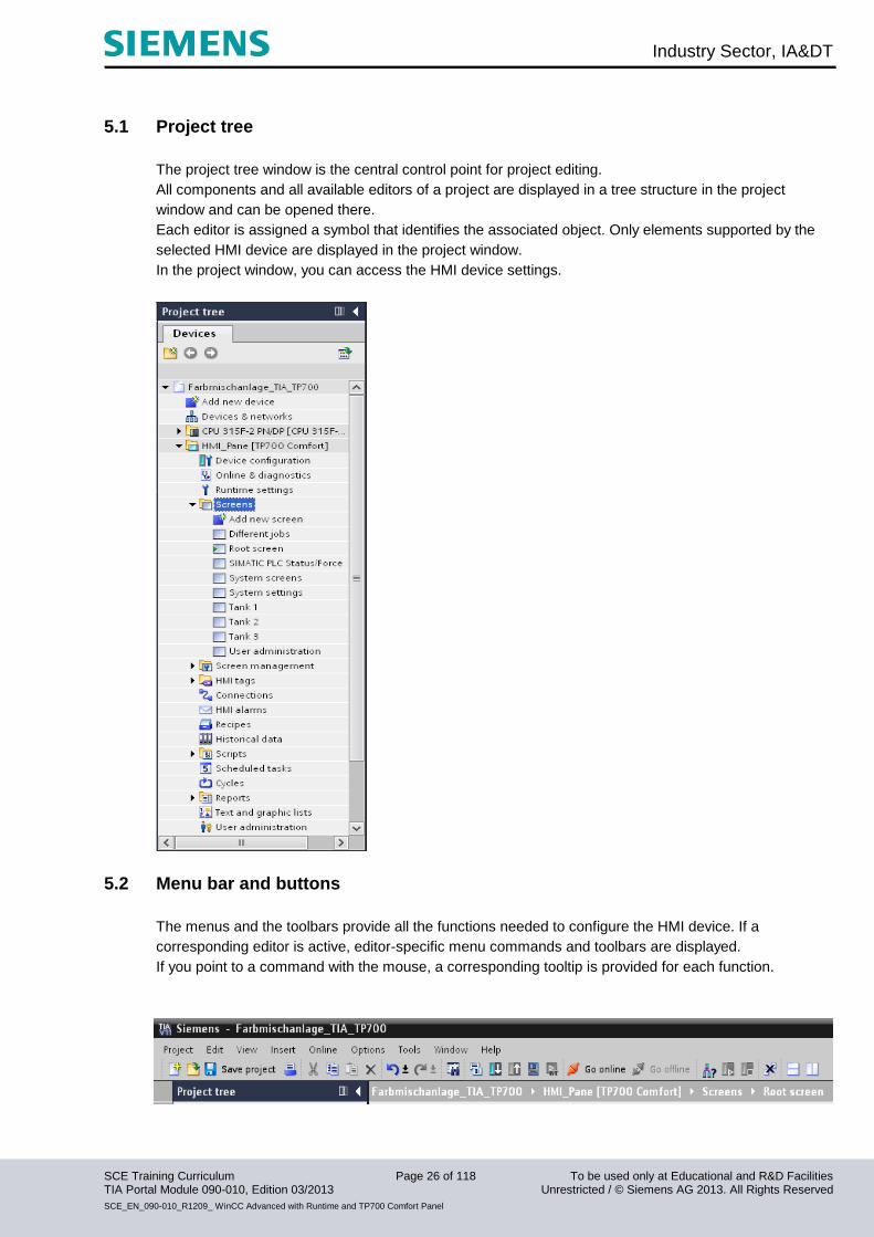
5.1 Project tree
The project tree window is the central control point for project editing.
All components and all available editors of a project are displayed in a tree structure in the project
window and can be opened there.
Each editor is assigned a symbol that identifies the associated object. Only elements supported by the
selected HMI device are displayed in the project window.
In the project window, you can access the HMI device settings.
5.2 Menu bar and buttons
The menus and the toolbars provide all the functions needed to configure the HMI device. If a
corresponding editor is active, editor-specific menu commands and toolbars are displayed.
If you point to a command with the mouse, a corresponding tooltip is provided for each function.
Industry Sector, IA&DT
SCE Training Curriculum Page 27 of 118 To be used only at Educational and R&D Facilities TIA Portal Module 090-010, Edition 03/2013 Unrestricted / © Siemens AG 2013. All Rights Reserved
SCE_EN_090-010_R1209_ WinCC Advanced with Runtime and TP700 Comfort Panel
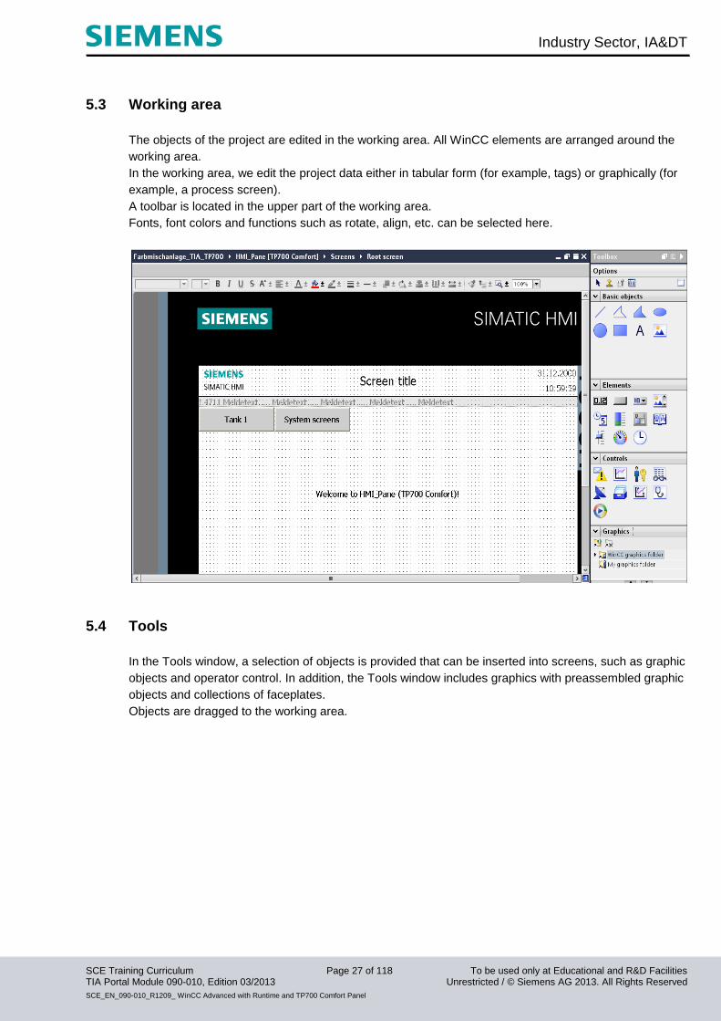
5.3 Working area
The objects of the project are edited in the working area. All WinCC elements are arranged around the
working area.
In the working area, we edit the project data either in tabular form (for example, tags) or graphically (for
example, a process screen).
A toolbar is located in the upper part of the working area.
Fonts, font colors and functions such as rotate, align, etc. can be selected here.
5.4 Tools
In the Tools window, a selection of objects is provided that can be inserted into screens, such as graphic
objects and operator control. In addition, the Tools window includes graphics with preassembled graphic
objects and collections of faceplates.
Objects are dragged to the working area.

Industry Sector, IA&DT
SCE Training Curriculum Page 28 of 118 To be used only at Educational and R&D Facilities TIA Portal Module 090-010, Edition 03/2013 Unrestricted / © Siemens AG 2013. All Rights Reserved
SCE_EN_090-010_R1209_ WinCC Advanced with Runtime and TP700 Comfort Panel
5.5 Properties window
In the properties window, you edit the properties of objects; for example, the color of screen objects.
The properties window is available only in certain editors.
In the properties window, the properties of the selected object are displayed arranged according to
categories. As soon as you exit an input field, the value changes become effective.
If you enter an invalid value, this field is highlighted in color.
To obtain information on the valid data range, for example, view the tooltip.
In addition, animations and events of the selected object are configured in the properties window; in this
case, for example, a screen change when the button is released.
5.6 Details view
The details view displays additional information on the object selected in the project tree.
Industry Sector, IA&DT
SCE Training Curriculum Page 29 of 118 To be used only at Educational and R&D Facilities TIA Portal Module 090-010, Edition 03/2013 Unrestricted / © Siemens AG 2013. All Rights Reserved
SCE_EN_090-010_R1209_ WinCC Advanced with Runtime and TP700 Comfort Panel
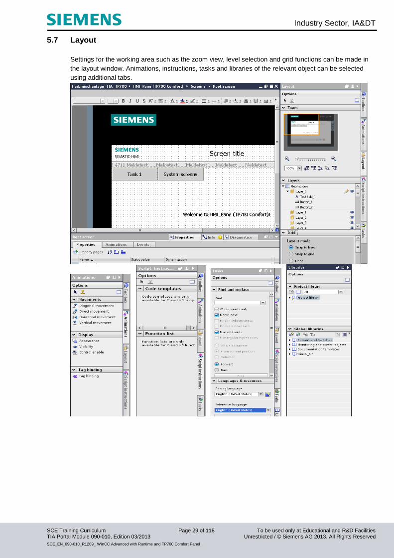
5.7 Layout
Settings for the working area such as the zoom view, level selection and grid functions can be made in
the layout window. Animations, instructions, tasks and libraries of the relevant object can be selected
using additional tabs.

Industry Sector, IA&DT
SCE Training Curriculum Page 30 of 118 To be used only at Educational and R&D Facilities TIA Portal Module 090-010, Edition 03/2013 Unrestricted / © Siemens AG 2013. All Rights Reserved
SCE_EN_090-010_R1209_ WinCC Advanced with Runtime and TP700 Comfort Panel
6. Device configuration of the TP700 Comfort Panel
To open, double-click the device configuration of the HMI_Panel [TP700 Comfort].
Industry Sector, IA&DT
SCE Training Curriculum Page 31 of 118 To be used only at Educational and R&D Facilities TIA Portal Module 090-010, Edition 03/2013 Unrestricted / © Siemens AG 2013. All Rights Reserved
SCE_EN_090-010_R1209_ WinCC Advanced with Runtime and TP700 Comfort Panel
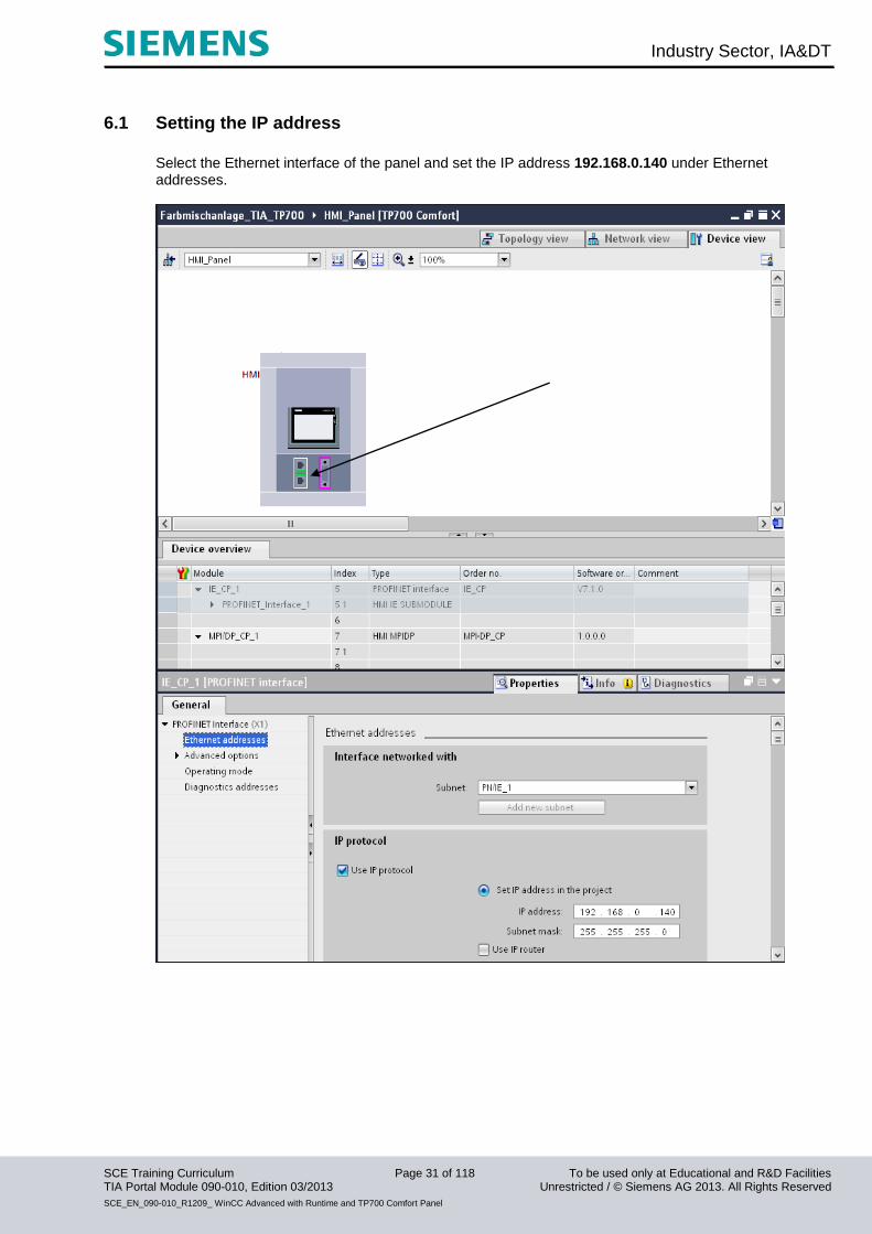
6.1 Setting the IP address
Select the Ethernet interface of the panel and set the IP address 192.168.0.140 under Ethernet addresses.
Industry Sector, IA&DT
SCE Training Curriculum Page 32 of 118 To be used only at Educational and R&D Facilities TIA Portal Module 090-010, Edition 03/2013 Unrestricted / © Siemens AG 2013. All Rights Reserved
SCE_EN_090-010_R1209_ WinCC Advanced with Runtime and TP700 Comfort Panel
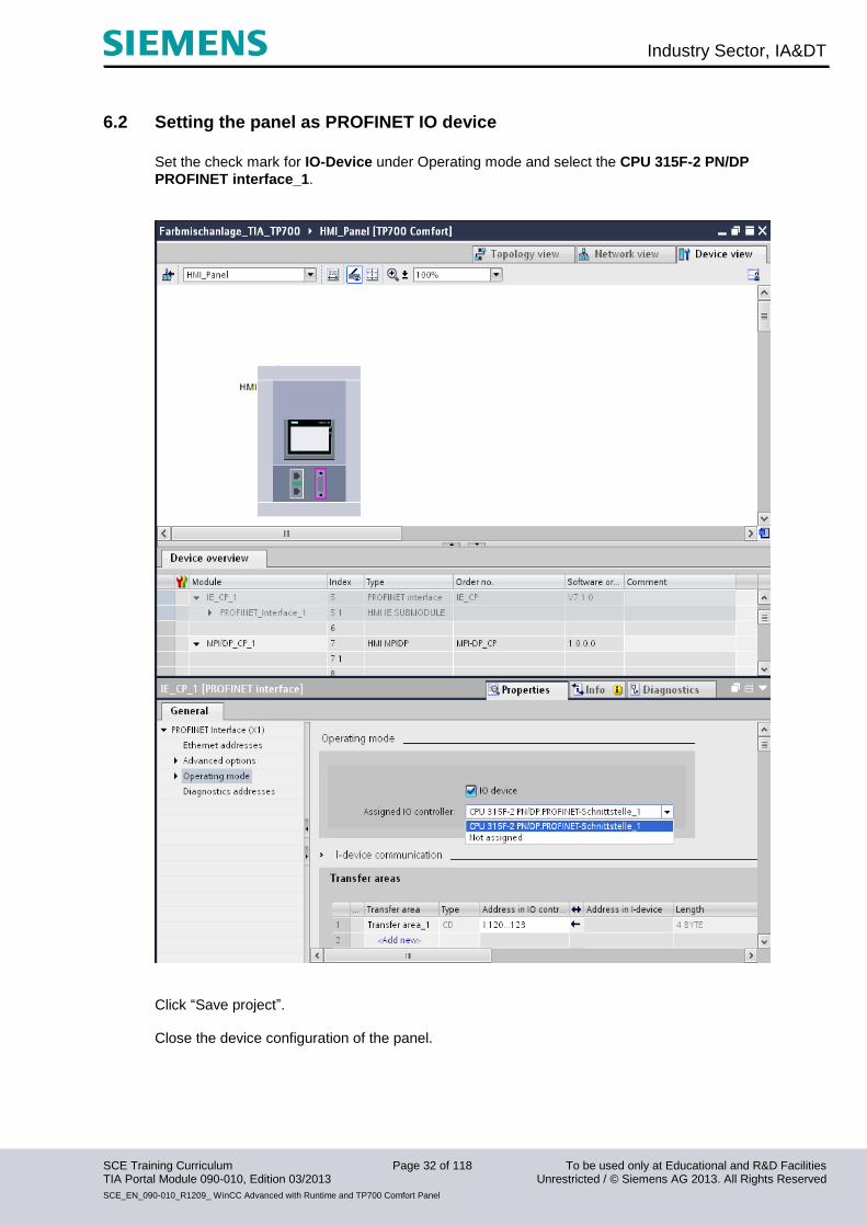
6.2 Setting the panel as PROFINET IO device
Set the check mark for IO-Device under Operating mode and select the CPU 315F-2 PN/DP
PROFINET interface_1.
Click “Save project”. Close the device configuration of the panel.
Industry Sector, IA&DT
SCE Training Curriculum Page 33 of 118 To be used only at Educational and R&D Facilities TIA Portal Module 090-010, Edition 03/2013 Unrestricted / © Siemens AG 2013. All Rights Reserved
SCE_EN_090-010_R1209_ WinCC Advanced with Runtime and TP700 Comfort Panel
7. Configuring screens A screen can consist of static and dynamic elements. Static elements, such as text and graphics, are not
updated by the controller.
Dynamic elements are connected to the controller and visualize current values from the controller’s
memory. Visualization can be in the form of alphanumeric displays, trends or bars. Dynamic elements
are also inputs on the HMI device that are written to the controller’s memory. Tags are used for the
connection with the controller.
To begin with, the four automatically generated screens are to be configured for our color mixing station.
Root screen
This screen is already set up automatically and is also defined as start screen.
The entire plant is displayed here.
You can switch the operating mode or start the mixing process, the manual operation of the mixer motor
and the opening of the drain valve using buttons.
The motion of the mixer and the states of the valves are displayed in graphic form.
The filling capacities of the individual admixtures are indicated via input fields.
Jumping to other screens should also be possible.
The "System screens" button can be used to make system settings on the panel, for example.
Tank 1
The valves from Tank 1 can be operated in manual mode in the Tank 1 screen. The maximum and
minimum filling capacity can be set on the sliders. The supply and drain valve can be opened or closed
using buttons (Open valve).
The valves are displayed in graphic form and change their color in the open state.
The fill level is displayed in red. When the maximum fill level has been reached, the supply valve is
closed in automatic mode. If the tank is completely full, the supply valve cannot be opened.
Other buttons are used to switch to other tanks or to the root screen.
Tank 2, Tank 3
The Tank 2 and Tank 3 screens are structured like the Tank 1 screen.
The valves and the fill level of Tank 2 are displayed in green.
The valves and the fill level of Tank 3 are displayed in blue.
Industry Sector, IA&DT
SCE Training Curriculum Page 34 of 118 To be used only at Educational and R&D Facilities TIA Portal Module 090-010, Edition 03/2013 Unrestricted / © Siemens AG 2013. All Rights Reserved
SCE_EN_090-010_R1209_ WinCC Advanced with Runtime and TP700 Comfort Panel
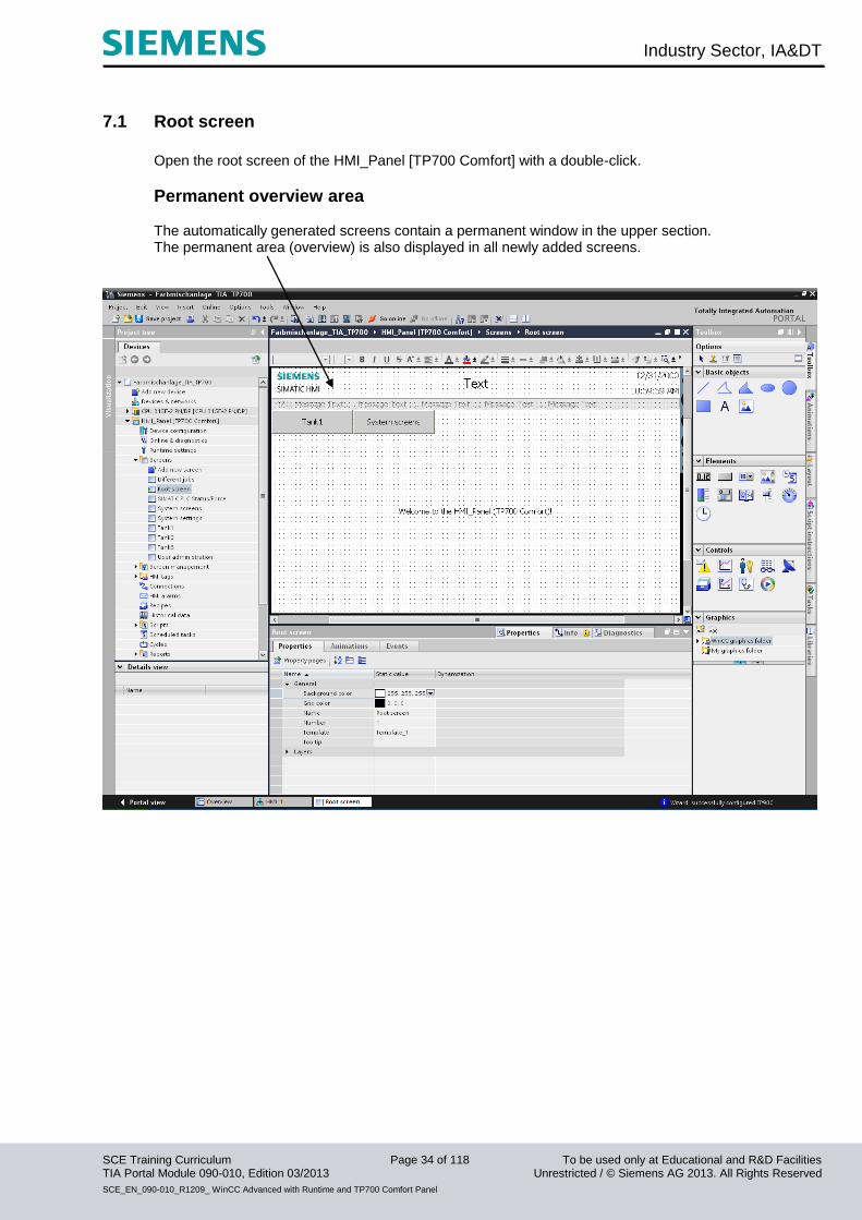
7.1 Root screen
Open the root screen of the HMI_Panel [TP700 Comfort] with a double-click.
Permanent overview area The automatically generated screens contain a permanent window in the upper section. The permanent area (overview) is also displayed in all newly added screens.

Industry Sector, IA&DT
SCE Training Curriculum Page 35 of 118 To be used only at Educational and R&D Facilities TIA Portal Module 090-010, Edition 03/2013 Unrestricted / © Siemens AG 2013. All Rights Reserved
SCE_EN_090-010_R1209_ WinCC Advanced with Runtime and TP700 Comfort Panel
In the permanent window, change the screen title to Color mixing station under General and the
Position & size and Margins of the text field under Layout.
Industry Sector, IA&DT
SCE Training Curriculum Page 36 of 118 To be used only at Educational and R&D Facilities TIA Portal Module 090-010, Edition 03/2013 Unrestricted / © Siemens AG 2013. All Rights Reserved
SCE_EN_090-010_R1209_ WinCC Advanced with Runtime and TP700 Comfort Panel
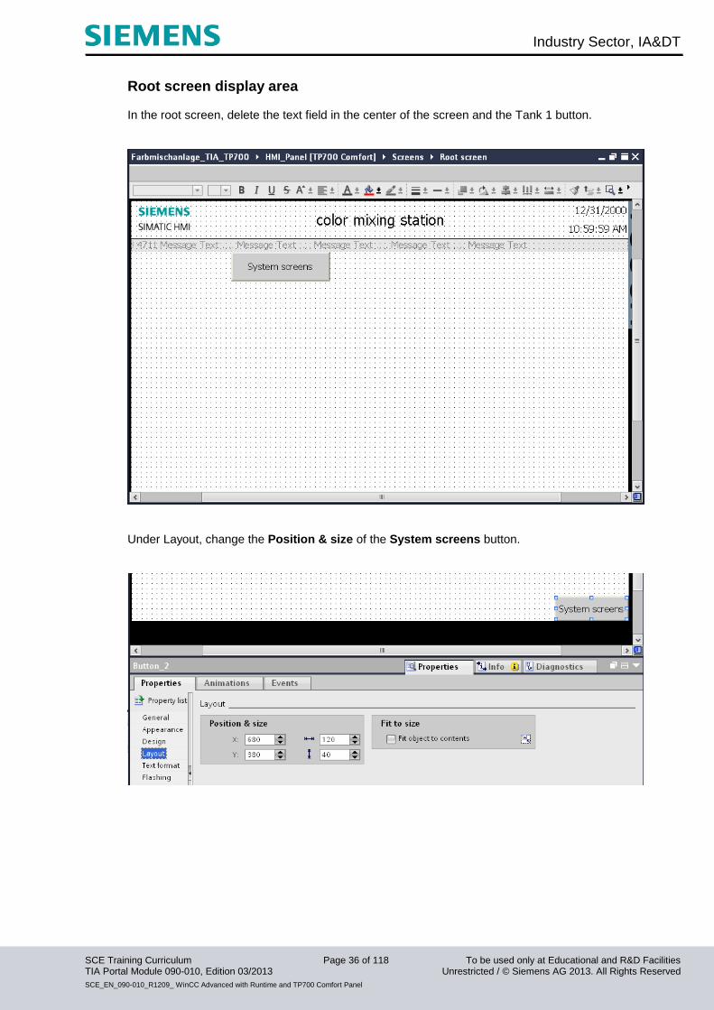
Root screen display area In the root screen, delete the text field in the center of the screen and the Tank 1 button.
Under Layout, change the Position & size of the System screens button.
Industry Sector, IA&DT
SCE Training Curriculum Page 37 of 118 To be used only at Educational and R&D Facilities TIA Portal Module 090-010, Edition 03/2013 Unrestricted / © Siemens AG 2013. All Rights Reserved
SCE_EN_090-010_R1209_ WinCC Advanced with Runtime and TP700 Comfort Panel
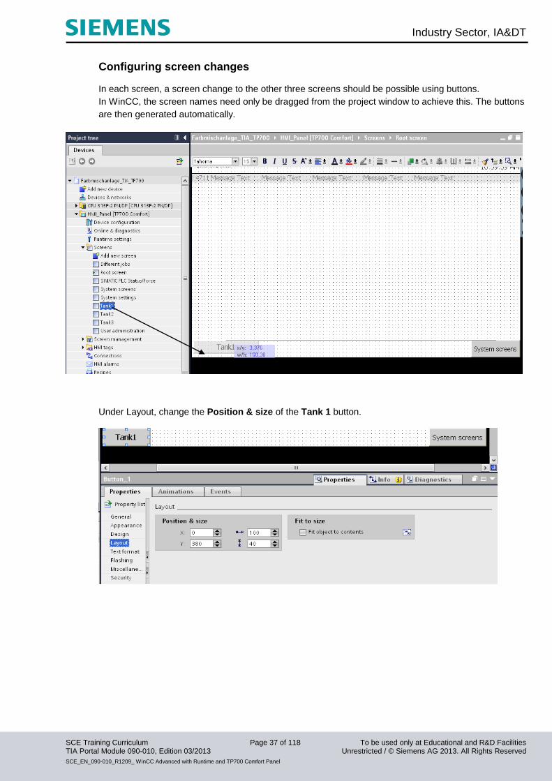
Configuring screen changes In each screen, a screen change to the other three screens should be possible using buttons.
In WinCC, the screen names need only be dragged from the project window to achieve this. The buttons
are then generated automatically.
Under Layout, change the Position & size of the Tank 1 button.

Industry Sector, IA&DT
SCE Training Curriculum Page 38 of 118 To be used only at Educational and R&D Facilities TIA Portal Module 090-010, Edition 03/2013 Unrestricted / © Siemens AG 2013. All Rights Reserved
SCE_EN_090-010_R1209_ WinCC Advanced with Runtime and TP700 Comfort Panel
Insert the Tank 2 button and change the Position & size under Layout.
Insert the Tank 3 button and change the Position & size under Layout.
Make sure to save the project occasionally.

Industry Sector, IA&DT
SCE Training Curriculum Page 39 of 118 To be used only at Educational and R&D Facilities TIA Portal Module 090-010, Edition 03/2013 Unrestricted / © Siemens AG 2013. All Rights Reserved
SCE_EN_090-010_R1209_ WinCC Advanced with Runtime and TP700 Comfort Panel
Inserting a graphic view Drag a graphic view to the working area of the root screen.

Industry Sector, IA&DT
SCE Training Curriculum Page 40 of 118 To be used only at Educational and R&D Facilities TIA Portal Module 090-010, Edition 03/2013 Unrestricted / © Siemens AG 2013. All Rights Reserved
SCE_EN_090-010_R1209_ WinCC Advanced with Runtime and TP700 Comfort Panel
You can now choose graphics from the list in the properties window of the graphic view
You can use the buttons to create new graphics from files or OLE objects.
The selected graphic appears in the preview window and can be inserted.
You have two options for inserting graphics.
First option
Click Create new graphic from file.
Industry Sector, IA&DT
SCE Training Curriculum Page 41 of 118 To be used only at Educational and R&D Facilities TIA Portal Module 090-010, Edition 03/2013 Unrestricted / © Siemens AG 2013. All Rights Reserved
SCE_EN_090-010_R1209_ WinCC Advanced with Runtime and TP700 Comfort Panel
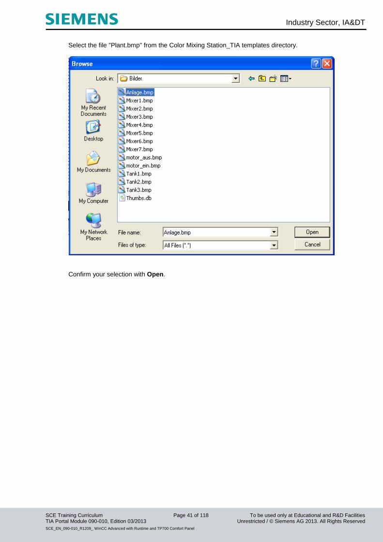
Select the file "Plant.bmp" from the Color Mixing Station_TIA templates directory.
Confirm your selection with Open.
Industry Sector, IA&DT
SCE Training Curriculum Page 42 of 118 To be used only at Educational and R&D Facilities TIA Portal Module 090-010, Edition 03/2013 Unrestricted / © Siemens AG 2013. All Rights Reserved
SCE_EN_090-010_R1209_ WinCC Advanced with Runtime and TP700 Comfort Panel
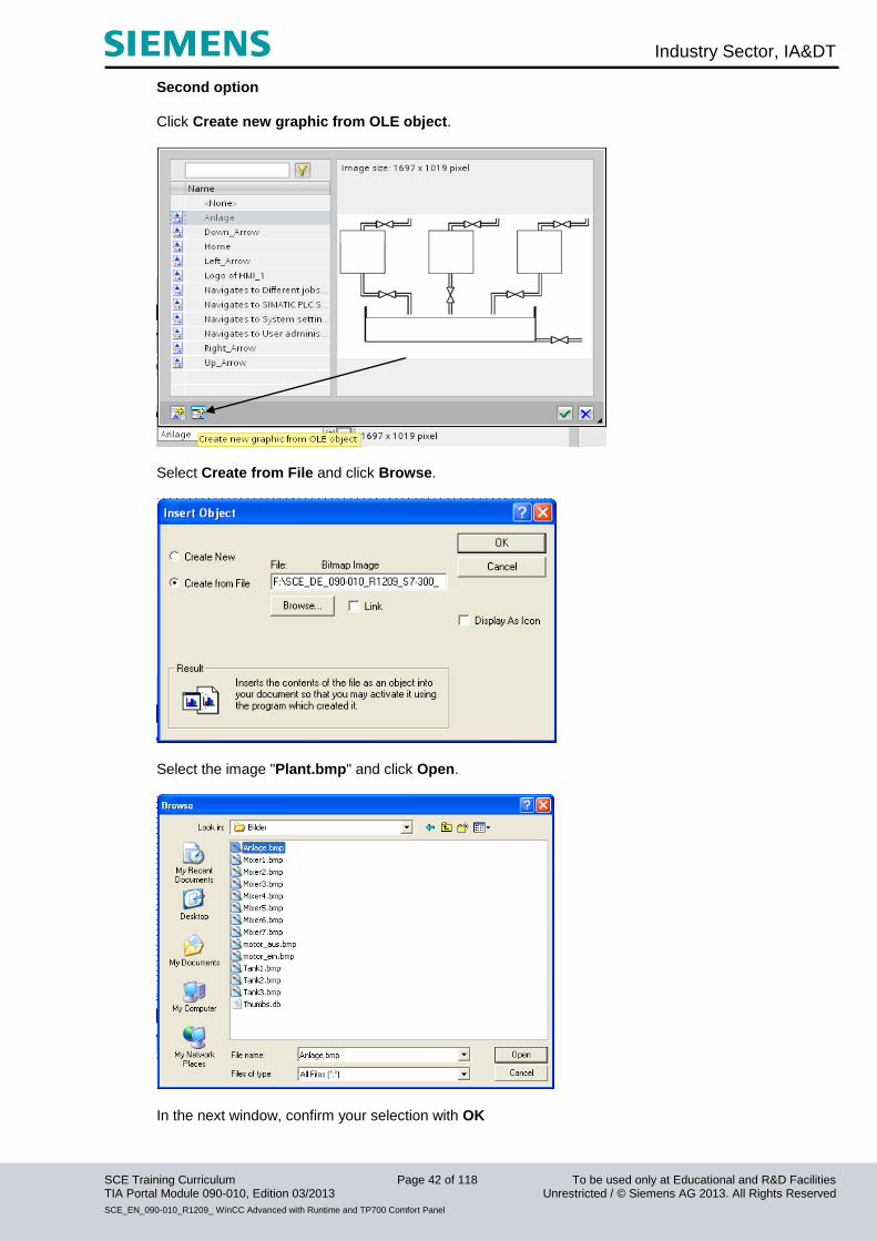
Second option
Click Create new graphic from OLE object.
Select Create from File and click Browse.
Select the image "Plant.bmp" and click Open.
In the next window, confirm your selection with OK

Industry Sector, IA&DT
SCE Training Curriculum Page 43 of 118 To be used only at Educational and R&D Facilities TIA Portal Module 090-010, Edition 03/2013 Unrestricted / © Siemens AG 2013. All Rights Reserved
SCE_EN_090-010_R1209_ WinCC Advanced with Runtime and TP700 Comfort Panel
.
Under Layout, change the Position & size of the graphic view.
Remember to save the project!
Industry Sector, IA&DT
SCE Training Curriculum Page 44 of 118 To be used only at Educational and R&D Facilities TIA Portal Module 090-010, Edition 03/2013 Unrestricted / © Siemens AG 2013. All Rights Reserved
SCE_EN_090-010_R1209_ WinCC Advanced with Runtime and TP700 Comfort Panel
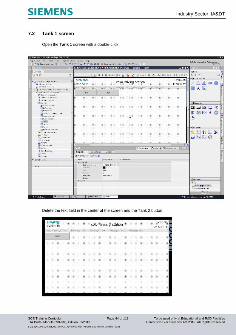
7.2 Tank 1 screen
Open the Tank 1 screen with a double-click.
Delete the text field in the center of the screen and the Tank 2 button.
Industry Sector, IA&DT
SCE Training Curriculum Page 45 of 118 To be used only at Educational and R&D Facilities TIA Portal Module 090-010, Edition 03/2013 Unrestricted / © Siemens AG 2013. All Rights Reserved
SCE_EN_090-010_R1209_ WinCC Advanced with Runtime and TP700 Comfort Panel
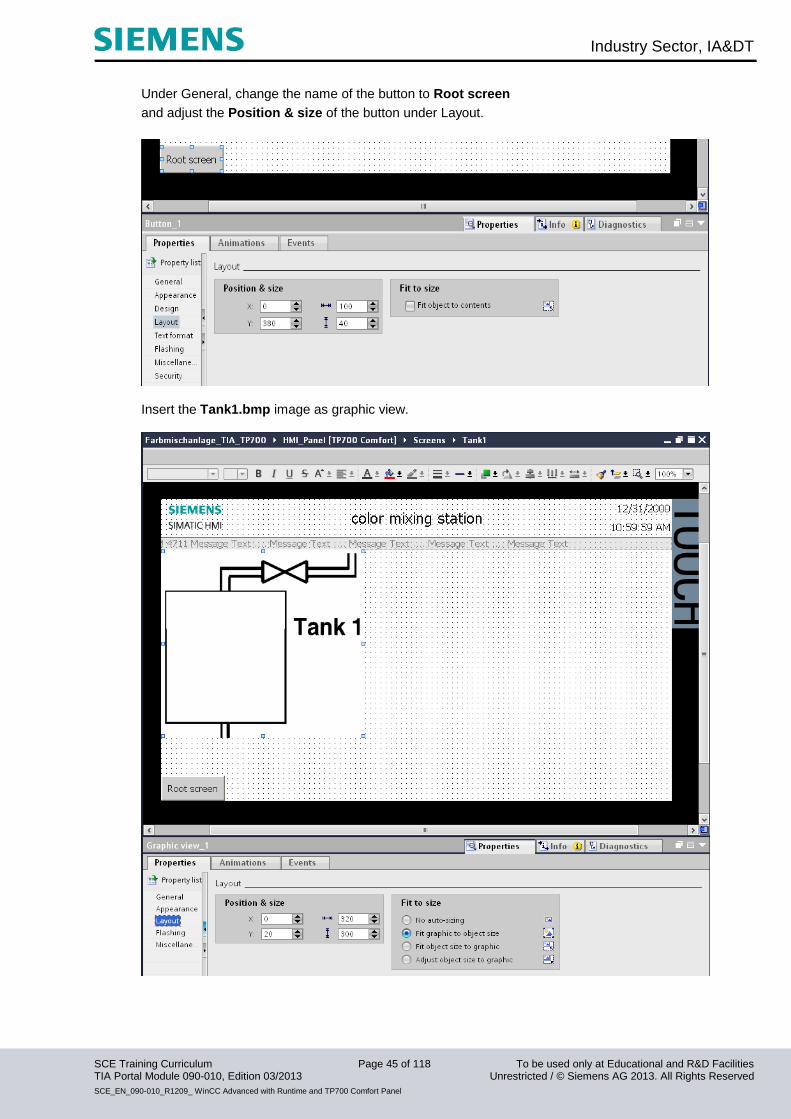
Under General, change the name of the button to Root screen
and adjust the Position & size of the button under Layout.
Insert the Tank1.bmp image as graphic view.
Industry Sector, IA&DT
SCE Training Curriculum Page 46 of 118 To be used only at Educational and R&D Facilities TIA Portal Module 090-010, Edition 03/2013 Unrestricted / © Siemens AG 2013. All Rights Reserved
SCE_EN_090-010_R1209_ WinCC Advanced with Runtime and TP700 Comfort Panel
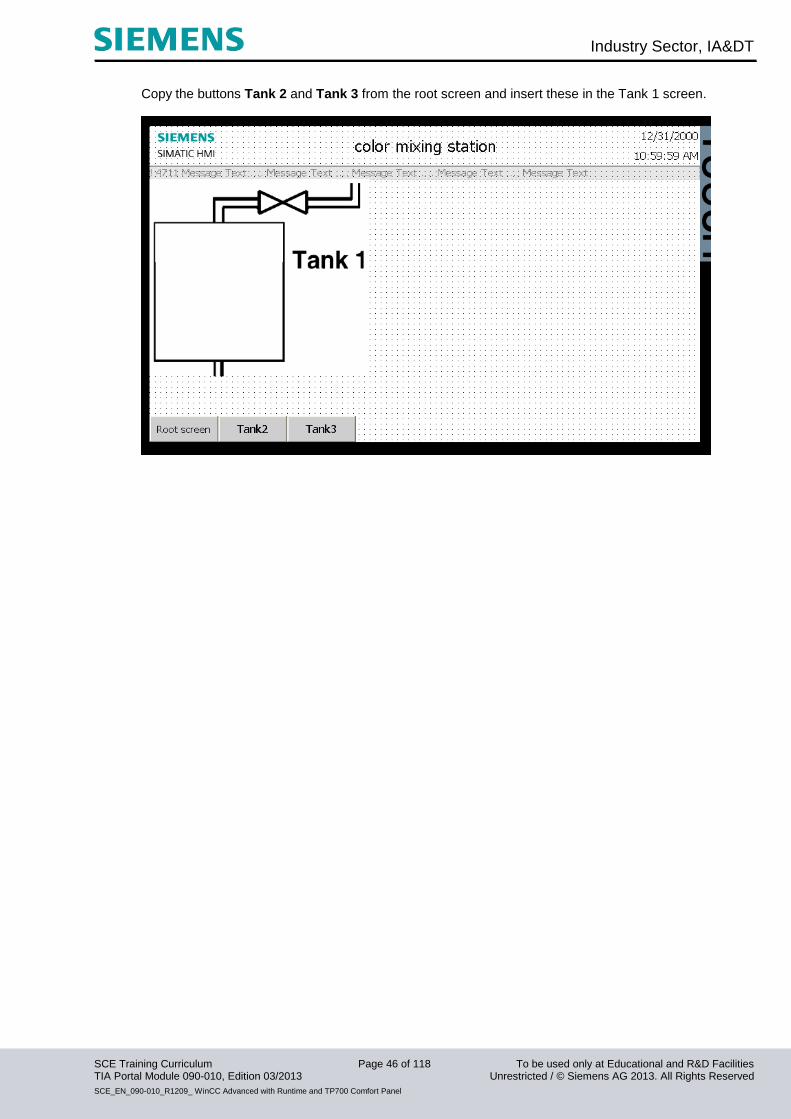
Copy the buttons Tank 2 and Tank 3 from the root screen and insert these in the Tank 1 screen.
Industry Sector, IA&DT
SCE Training Curriculum Page 47 of 118 To be used only at Educational and R&D Facilities TIA Portal Module 090-010, Edition 03/2013 Unrestricted / © Siemens AG 2013. All Rights Reserved
SCE_EN_090-010_R1209_ WinCC Advanced with Runtime and TP700 Comfort Panel
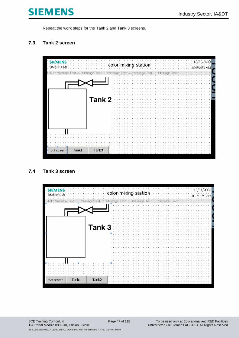
Repeat the work steps for the Tank 2 and Tank 3 screens.
7.3 Tank 2 screen
7.4 Tank 3 screen
Industry Sector, IA&DT
SCE Training Curriculum Page 48 of 118 To be used only at Educational and R&D Facilities TIA Portal Module 090-010, Edition 03/2013 Unrestricted / © Siemens AG 2013. All Rights Reserved
SCE_EN_090-010_R1209_ WinCC Advanced with Runtime and TP700 Comfort Panel
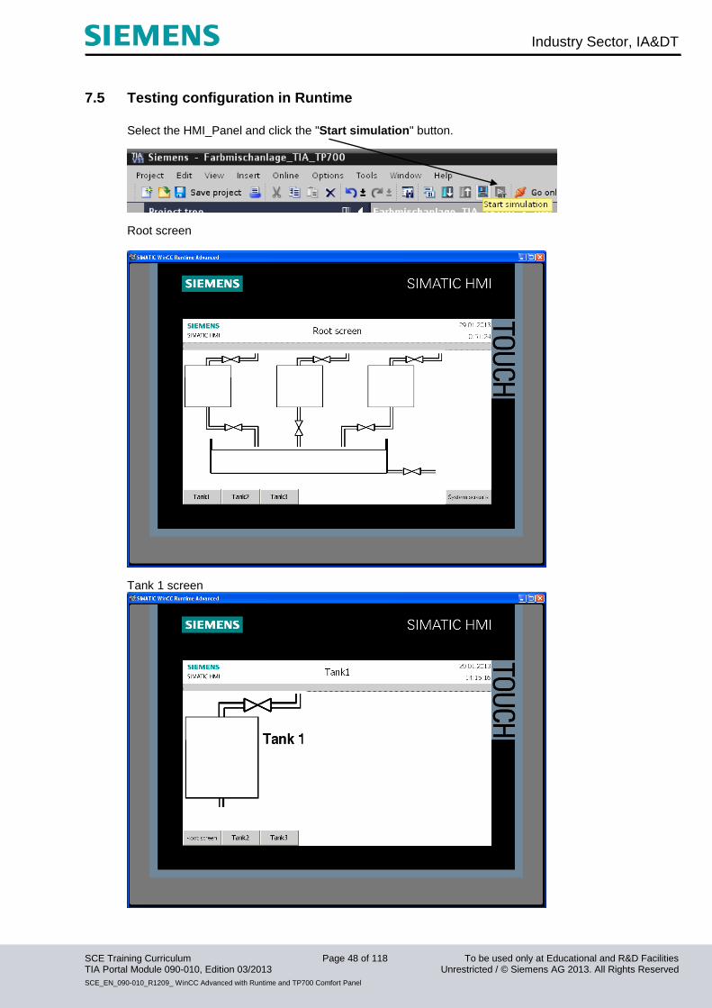
7.5 Testing configuration in Runtime
Select the HMI_Panel and click the "Start simulation" button.
Root screen
Tank 1 screen

Industry Sector, IA&DT
SCE Training Curriculum Page 49 of 118 To be used only at Educational and R&D Facilities TIA Portal Module 090-010, Edition 03/2013 Unrestricted / © Siemens AG 2013. All Rights Reserved
SCE_EN_090-010_R1209_ WinCC Advanced with Runtime and TP700 Comfort Panel
Tank 2 screen
Tank 3 screen
Test the function of the buttons in all screens
Industry Sector, IA&DT
SCE Training Curriculum Page 50 of 118 To be used only at Educational and R&D Facilities TIA Portal Module 090-010, Edition 03/2013 Unrestricted / © Siemens AG 2013. All Rights Reserved
SCE_EN_090-010_R1209_ WinCC Advanced with Runtime and TP700 Comfort Panel
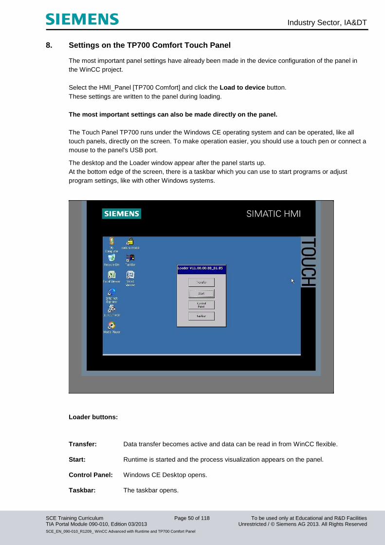
8. Settings on the TP700 Comfort Touch Panel The most important panel settings have already been made in the device configuration of the panel in
the WinCC project.
Select the HMI_Panel [TP700 Comfort] and click the Load to device button.
These settings are written to the panel during loading.
The most important settings can also be made directly on the panel.
The Touch Panel TP700 runs under the Windows CE operating system and can be operated, like all
touch panels, directly on the screen. To make operation easier, you should use a touch pen or connect a
mouse to the panel's USB port.
The desktop and the Loader window appear after the panel starts up.
At the bottom edge of the screen, there is a taskbar which you can use to start programs or adjust
program settings, like with other Windows systems.
Loader buttons:
Transfer: Data transfer becomes active and data can be read in from WinCC flexible.
Start: Runtime is started and the process visualization appears on the panel.
Control Panel: Windows CE Desktop opens.
Taskbar: The taskbar opens.
Industry Sector, IA&DT
SCE Training Curriculum Page 51 of 118 To be used only at Educational and R&D Facilities TIA Portal Module 090-010, Edition 03/2013 Unrestricted / © Siemens AG 2013. All Rights Reserved
SCE_EN_090-010_R1209_ WinCC Advanced with Runtime and TP700 Comfort Panel
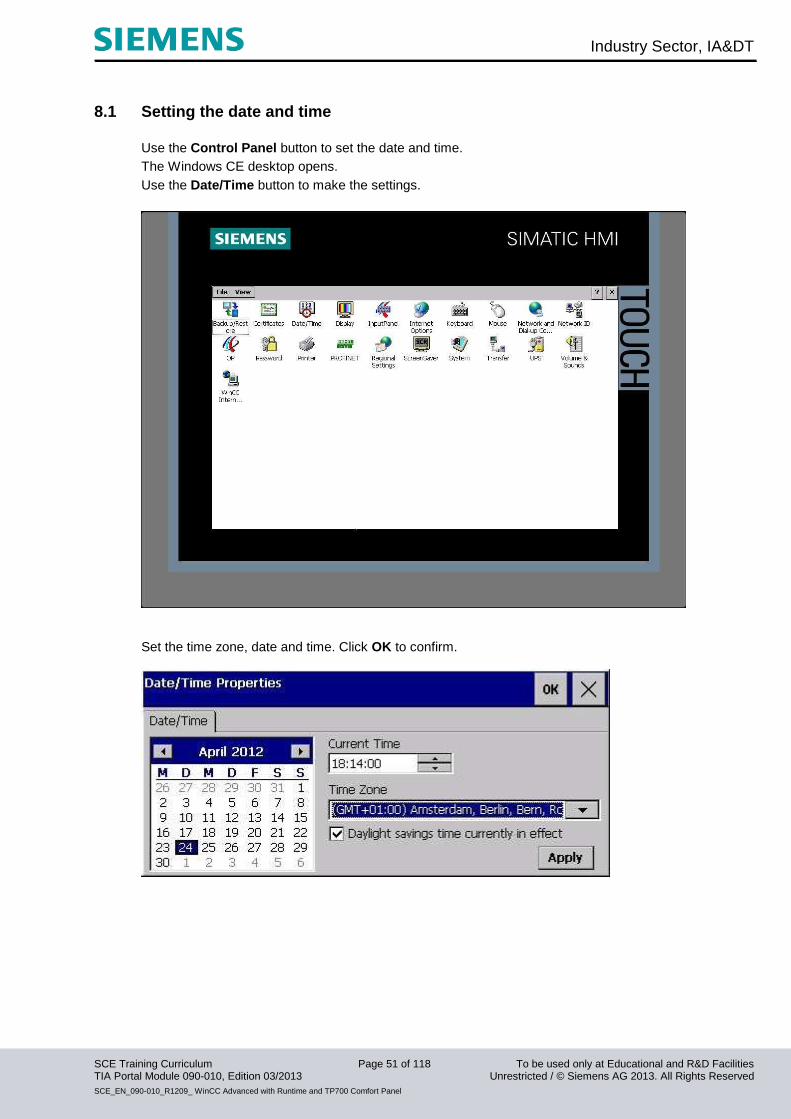
8.1 Setting the date and time
Use the Control Panel button to set the date and time.
The Windows CE desktop opens.
Use the Date/Time button to make the settings.
Set the time zone, date and time. Click OK to confirm.
Industry Sector, IA&DT
SCE Training Curriculum Page 52 of 118 To be used only at Educational and R&D Facilities TIA Portal Module 090-010, Edition 03/2013 Unrestricted / © Siemens AG 2013. All Rights Reserved
SCE_EN_090-010_R1209_ WinCC Advanced with Runtime and TP700 Comfort Panel
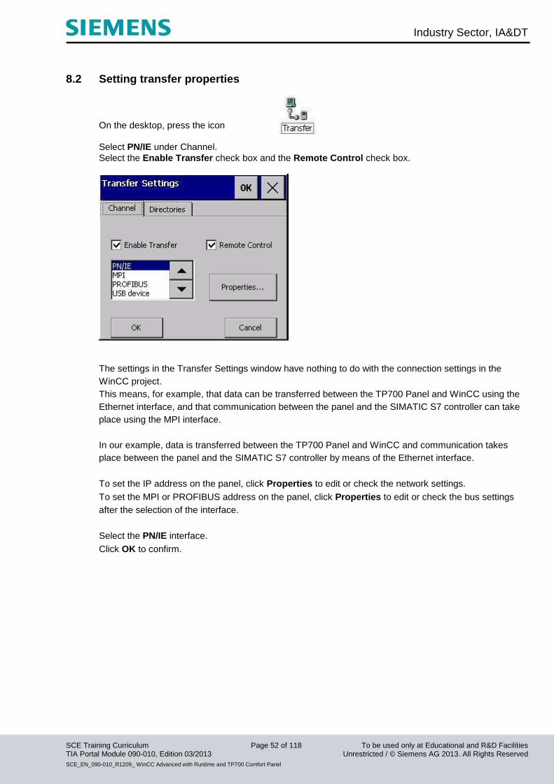
8.2 Setting transfer properties
On the desktop, press the icon
Select PN/IE under Channel.
Select the Enable Transfer check box and the Remote Control check box.
The settings in the Transfer Settings window have nothing to do with the connection settings in the
WinCC project.
This means, for example, that data can be transferred between the TP700 Panel and WinCC using the
Ethernet interface, and that communication between the panel and the SIMATIC S7 controller can take
place using the MPI interface.
In our example, data is transferred between the TP700 Panel and WinCC and communication takes
place between the panel and the SIMATIC S7 controller by means of the Ethernet interface.
To set the IP address on the panel, click Properties to edit or check the network settings.
To set the MPI or PROFIBUS address on the panel, click Properties to edit or check the bus settings
after the selection of the interface.
Select the PN/IE interface.
Click OK to confirm.
Industry Sector, IA&DT
SCE Training Curriculum Page 53 of 118 To be used only at Educational and R&D Facilities TIA Portal Module 090-010, Edition 03/2013 Unrestricted / © Siemens AG 2013. All Rights Reserved
SCE_EN_090-010_R1209_ WinCC Advanced with Runtime and TP700 Comfort Panel
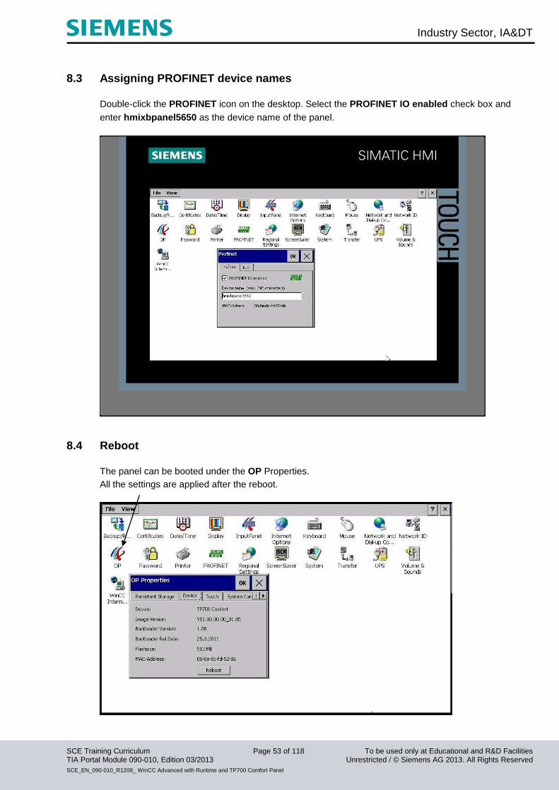
8.3 Assigning PROFINET device names
Double-click the PROFINET icon on the desktop. Select the PROFINET IO enabled check box and
enter hmixbpanel5650 as the device name of the panel.
8.4 Reboot
The panel can be booted under the OP Properties.
All the settings are applied after the reboot.
Industry Sector, IA&DT
SCE Training Curriculum Page 54 of 118 To be used only at Educational and R&D Facilities TIA Portal Module 090-010, Edition 03/2013 Unrestricted / © Siemens AG 2013. All Rights Reserved
SCE_EN_090-010_R1209_ WinCC Advanced with Runtime and TP700 Comfort Panel
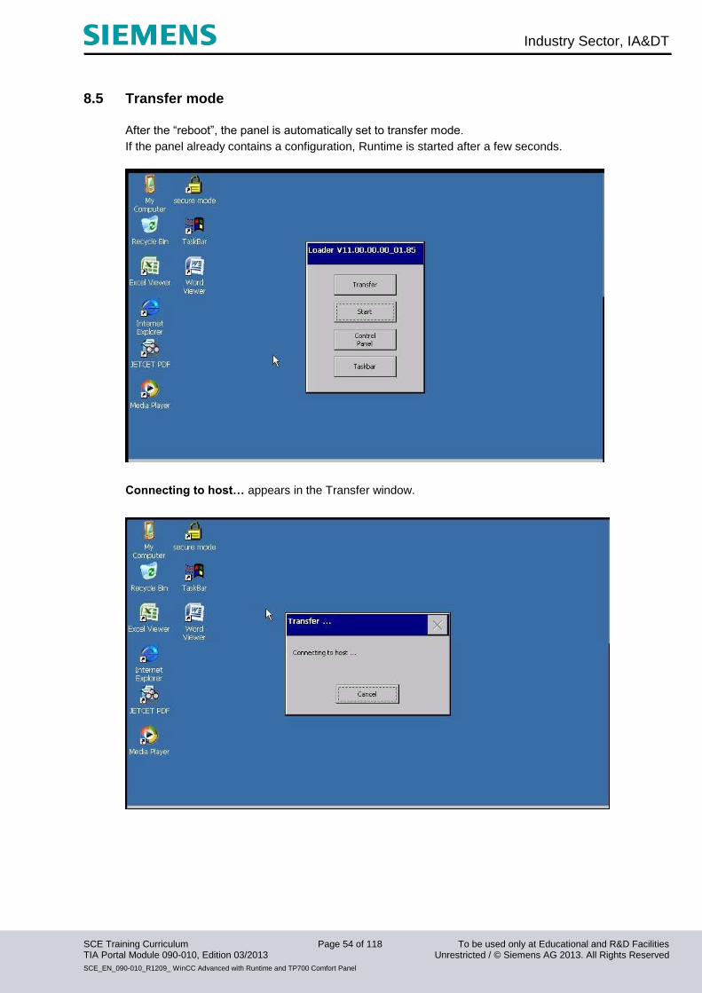
8.5 Transfer mode
After the “reboot”, the panel is automatically set to transfer mode.
If the panel already contains a configuration, Runtime is started after a few seconds.
Connecting to host… appears in the Transfer window.

Industry Sector, IA&DT
SCE Training Curriculum Page 55 of 118 To be used only at Educational and R&D Facilities TIA Portal Module 090-010, Edition 03/2013 Unrestricted / © Siemens AG 2013. All Rights Reserved
SCE_EN_090-010_R1209_ WinCC Advanced with Runtime and TP700 Comfort Panel
8.6 Configuring a connection
Until now, we have worked in our project without access to the SIMATIC S7 controller.
We also want to display fill levels and enter fill quantities on our panel.
For operating and display objects that access the process values of a controller, a connection to the
controller has to be configured first.
Here, you specify how and via which interface the panel communicates with the controller.
Double-click Connections in the project window.
All parameters have already been set by the settings in the device configuration.
Save the project.
The bus error LED on the CPU goes out after successful loading to the panel.
Note
To create a new connection, double click the free field in the first column.
Change the connection parameters of the newly created connection.
Industry Sector, IA&DT
SCE Training Curriculum Page 56 of 118 To be used only at Educational and R&D Facilities TIA Portal Module 090-010, Edition 03/2013 Unrestricted / © Siemens AG 2013. All Rights Reserved
SCE_EN_090-010_R1209_ WinCC Advanced with Runtime and TP700 Comfort Panel
9. Display and operating objects
Display and operating objects are graphic elements used to design process screens.
All display and operating objects behave dynamically in Runtime.
In addition, you can make the properties of objects dynamic.
An example of this is the graphic of a tank whose fill level changes in the display depending on the
corresponding process value.
Another example of the dynamic behavior of an object is a button that triggers a specific function.
Essentially, you can assign dynamic properties to any graphic object.
You have the following configuration options: - The appearance of the object changes: color and flash behavior.
- The object moves on the screen.
- The object is shown or hidden.
The following additional options are available for operator controls: - An object is enabled or locked for operating.
- Operator input, such as clicking an object, triggers an event. The configured response to this event
is to work through a function list.
9.1 Layers
Layers and nesting of objects within levels are used for the differential display and editing of screen
objects.
A screen has 32 layers. Objects can be inserted at every layer. The assignment of an object to a layer
determines the nesting of an object in the screen. Objects of layer 0 are located in the screen
background, while objects of layer 31 are located in the foreground.
The objects are also staggered within each layer.
In the creation of a process screen, the objects of an individual layer are arranged by default in the order
of their configuration. The first object inserted is located at the very rear of the layer. Each further object
is placed one position further to the front.
It is possible to change the position of objects to each other within the layer.
There is always one active layer. When you add new objects to a screen, these are assigned to the
active layer as standard. The number of the active layer is indicated in the "Layer" toolbar. The active
layer is highlighted in color in the layer pane.
When you open a screen, all 32 layers of the screen are always displayed.
You can use the layer pane after opening the screen to hide all layers except the active layer. You then
explicitly edit objects of the active layer.

Industry Sector, IA&DT
SCE Training Curriculum Page 57 of 118 To be used only at Educational and R&D Facilities TIA Portal Module 090-010, Edition 03/2013 Unrestricted / © Siemens AG 2013. All Rights Reserved
SCE_EN_090-010_R1209_ WinCC Advanced with Runtime and TP700 Comfort Panel
9.2 Basic objects
Symbol Object Notes
"Line" You can choose straight, rounded or arrow-shaped line ends
"Polyline" A "polyline" consists of linked paths and may have any number of vertices.
The vertices are numbered in the order of their creation. You can modify or
delete vertices individually. You can choose straight, rounded or arrow-
shaped line ends for the polyline. The polyline is an open object. Even if the
start and end points have the same coordinates, the area they enclose
cannot be filled in.
"Polygon" The vertices of a polygon are numbered in the order of their creation. You
can modify or delete vertices individually. You can fill a polygon with a color
or a pattern.
"Ellipsis" You can fill an ellipsis with a color or a pattern.
"Circle" You can fill a circle with a color or a pattern.
"Rectangle“ You can set any rounding for the vertices of a rectangle. You can fill a
rectangle with a color or a pattern.
"Text field" In a text field, you display one row or multiple rows of text and assign font
colors and fonts to this text. You can fill a text field with a color or a pattern.
"I/O field" An I/O field can be assigned the following functions in Runtime:
Output of tag values
Input of values by the operator; the input values are stored in a tag
Combined input and output; in this case, the operator can edit the
output tag values and thus reset them.
You can define limits for the tag values shown in the I/O field.
If you want to hide the operator input in Runtime, configure "Hidden input".
"Date/time
field"
A date/time field may have the following functions in Runtime:
Output of the date and time
Combined input and output; in this case, the operator can edit the
output values and thus reset the date or time.
The system time or corresponding tags can be used as the source for the
date and time.
You can choose to have the date displayed in detail (e.g. Tuesday,
December 31, 2003) or in short form (12/31/2003).
Industry Sector, IA&DT
SCE Training Curriculum Page 58 of 118 To be used only at Educational and R&D Facilities TIA Portal Module 090-010, Edition 03/2013 Unrestricted / © Siemens AG 2013. All Rights Reserved
SCE_EN_090-010_R1209_ WinCC Advanced with Runtime and TP700 Comfort Panel
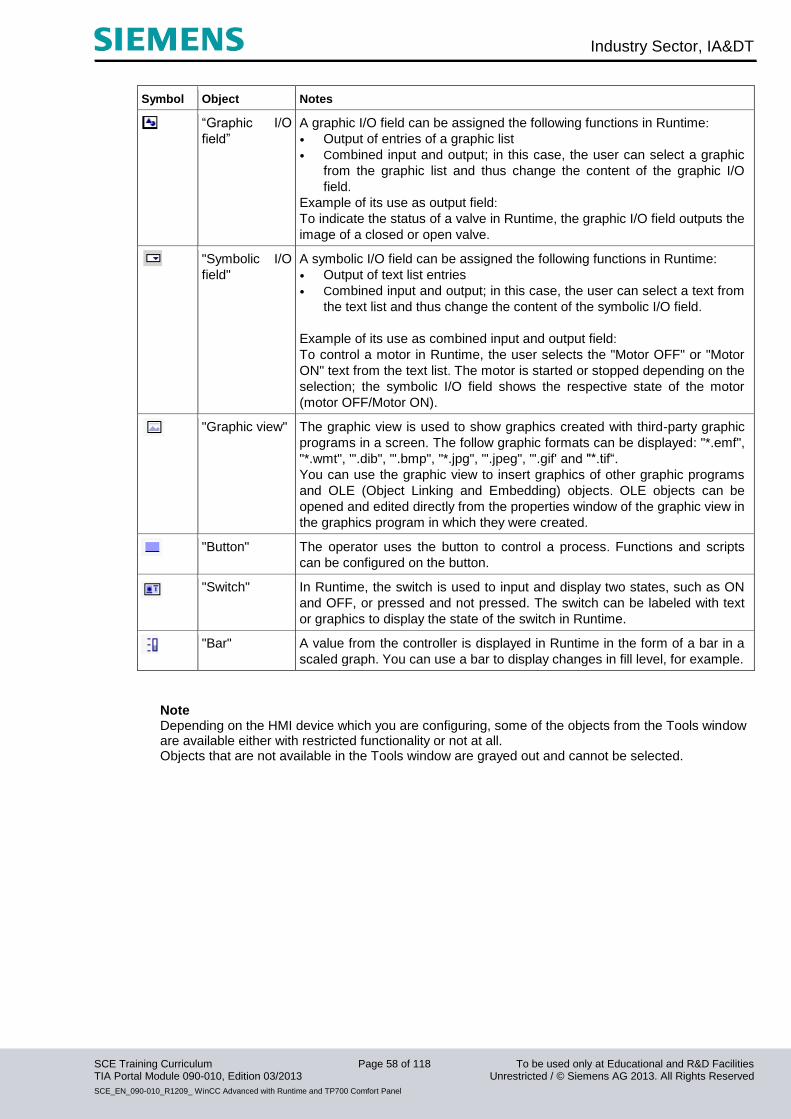
Symbol Object Notes
“Graphic I/O
field”
A graphic I/O field can be assigned the following functions in Runtime:
Output of entries of a graphic list
Combined input and output; in this case, the user can select a graphic
from the graphic list and thus change the content of the graphic I/O
field.
Example of its use as output field:
To indicate the status of a valve in Runtime, the graphic I/O field outputs the
image of a closed or open valve.
"Symbolic I/O
field"
A symbolic I/O field can be assigned the following functions in Runtime:
Output of text list entries
Combined input and output; in this case, the user can select a text from
the text list and thus change the content of the symbolic I/O field.
Example of its use as combined input and output field:
To control a motor in Runtime, the user selects the "Motor OFF" or "Motor
ON" text from the text list. The motor is started or stopped depending on the
selection; the symbolic I/O field shows the respective state of the motor
(motor OFF/Motor ON).
"Graphic view" The graphic view is used to show graphics created with third-party graphic
programs in a screen. The follow graphic formats can be displayed: "*.emf",
"*.wmt", "'.dib", "'.bmp", "*.jpg", "'.jpeg", "'.gif' and "*.tif“.
You can use the graphic view to insert graphics of other graphic programs
and OLE (Object Linking and Embedding) objects. OLE objects can be
opened and edited directly from the properties window of the graphic view in
the graphics program in which they were created.
"Button" The operator uses the button to control a process. Functions and scripts
can be configured on the button.
"Switch" In Runtime, the switch is used to input and display two states, such as ON
and OFF, or pressed and not pressed. The switch can be labeled with text
or graphics to display the state of the switch in Runtime.
"Bar" A value from the controller is displayed in Runtime in the form of a bar in a
scaled graph. You can use a bar to display changes in fill level, for example.
Note Depending on the HMI device which you are configuring, some of the objects from the Tools window are available either with restricted functionality or not at all. Objects that are not available in the Tools window are grayed out and cannot be selected.

Industry Sector, IA&DT
SCE Training Curriculum Page 59 of 118 To be used only at Educational and R&D Facilities TIA Portal Module 090-010, Edition 03/2013 Unrestricted / © Siemens AG 2013. All Rights Reserved
SCE_EN_090-010_R1209_ WinCC Advanced with Runtime and TP700 Comfort Panel
9.3 Enhanced objects
Symbol Object Description
"SIider” The operator can use the slider to read and input numerical values as
follows.
As indicating element, the position of the slider shows the current
value from the controller
To input widths, the operator moves the slider to the required
position.
The slider can only be configured with vertical sliding direction.
"Clock" In Runtime, the clock is used to display the system time in either analog
or digital format on the HMI device.
"Status/Force" Status/Force gives the operator direct read and write access from the
HMI device to individual address areas in the connected SIMATIC S7 or
SIMATIC S5.
"Sm@rtClient
view"
The operator can use Sm@rtClient view to monitor and operate another
HMI device of the plant.
"HTML browser" The operator can use the HTML browser to view websites.
"User view" In WinCC flexible, you can protect the operation of screen objects using
passwords. In Runtime, the user view allows an administrator to manage
the users on the HMI device.
Users that do not have administrator rights can change their passwords
in Runtime.
"Pointer
instrument"
In Runtime, you can use the pointer instrument to display numerical
values using a pointer position. It is possible to configure the appearance
of the pointer instrument. You can, for example, change the background
graphic or the scale design.
"Trend view" You can use the trend view to simultaneously display multiple trends with
values from the controller or from a log. The axes of the trend view can
be configured (scales, units etc.).
"Recipe view" The operator can use the recipe view to display, edit and manage data
records in Runtime.
"Alarm view" The operator can use the alarm view to display selected alarms or alarm
events from the alarm buffer or alarm log in Runtime.
"Alarm window" The operator can use the alarm window to display selected alarms or
alarm events from the alarm buffer or alarm log in Runtime. You can only
configure the alarm window in the template.
"Alarm indicator" The alarm indicator signals to the operator that alarms that need to be
acknowledged have arrived and have not yet been acknowledged.
You can only configure the alarm indicator in the template.

Industry Sector, IA&DT
SCE Training Curriculum Page 60 of 118 To be used only at Educational and R&D Facilities TIA Portal Module 090-010, Edition 03/2013 Unrestricted / © Siemens AG 2013. All Rights Reserved
SCE_EN_090-010_R1209_ WinCC Advanced with Runtime and TP700 Comfort Panel
10. Display and operating objects in the "Color mixing station" project
10.1. Configuring display and operating objects in the “Tank 1” screen
A bar, two sliders and two buttons are configured to begin with. Afterwards, the supply and drain valves are to be animated in color.
Configuring the bar view You are going to configure a bar to display the current fill level of Tank 1. Drag a bar to the Tank 1 screen.
Industry Sector, IA&DT
SCE Training Curriculum Page 61 of 118 To be used only at Educational and R&D Facilities TIA Portal Module 090-010, Edition 03/2013 Unrestricted / © Siemens AG 2013. All Rights Reserved
SCE_EN_090-010_R1209_ WinCC Advanced with Runtime and TP700 Comfort Panel
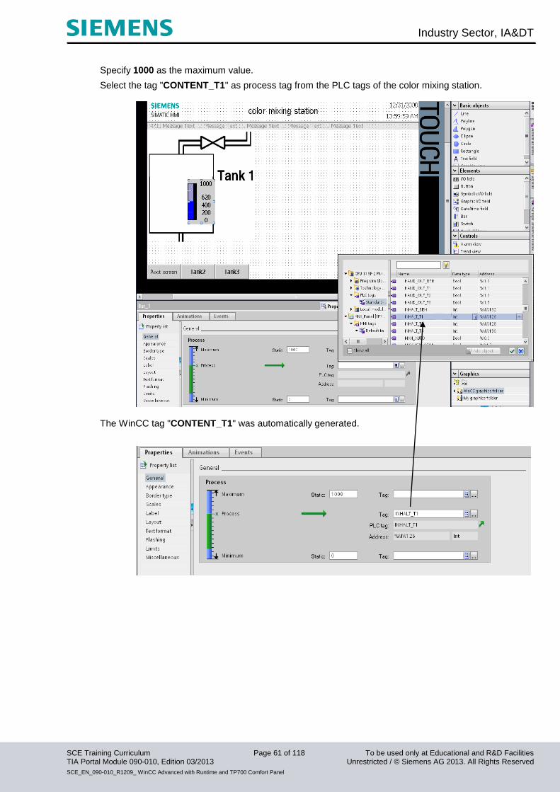
Specify 1000 as the maximum value.
Select the tag "CONTENT_T1" as process tag from the PLC tags of the color mixing station.
The WinCC tag "CONTENT_T1" was automatically generated.
Industry Sector, IA&DT
SCE Training Curriculum Page 62 of 118 To be used only at Educational and R&D Facilities TIA Portal Module 090-010, Edition 03/2013 Unrestricted / © Siemens AG 2013. All Rights Reserved
SCE_EN_090-010_R1209_ WinCC Advanced with Runtime and TP700 Comfort Panel
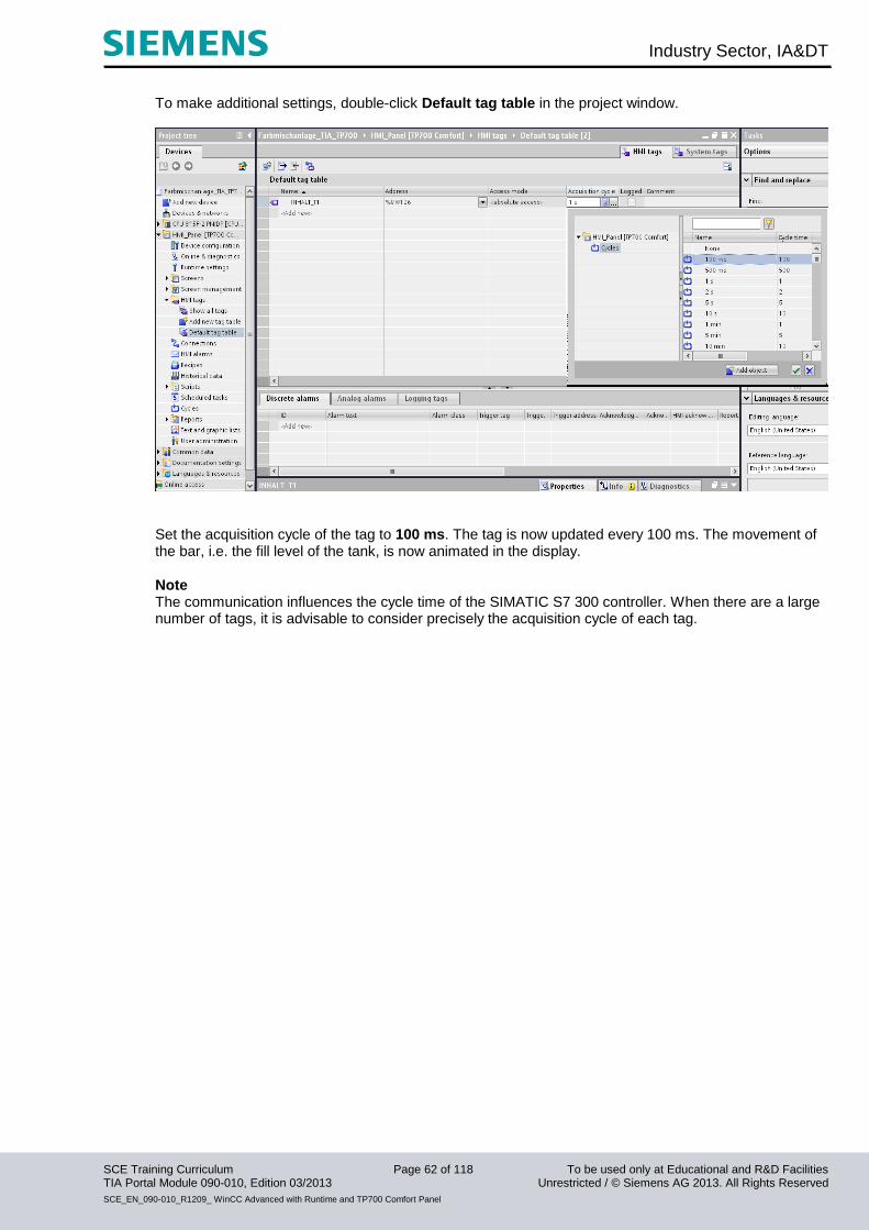
To make additional settings, double-click Default tag table in the project window.
Set the acquisition cycle of the tag to 100 ms. The tag is now updated every 100 ms. The movement of the bar, i.e. the fill level of the tank, is now animated in the display.
Note The communication influences the cycle time of the SIMATIC S7 300 controller. When there are a large number of tags, it is advisable to consider precisely the acquisition cycle of each tag.
Industry Sector, IA&DT
SCE Training Curriculum Page 63 of 118 To be used only at Educational and R&D Facilities TIA Portal Module 090-010, Edition 03/2013 Unrestricted / © Siemens AG 2013. All Rights Reserved
SCE_EN_090-010_R1209_ WinCC Advanced with Runtime and TP700 Comfort Panel
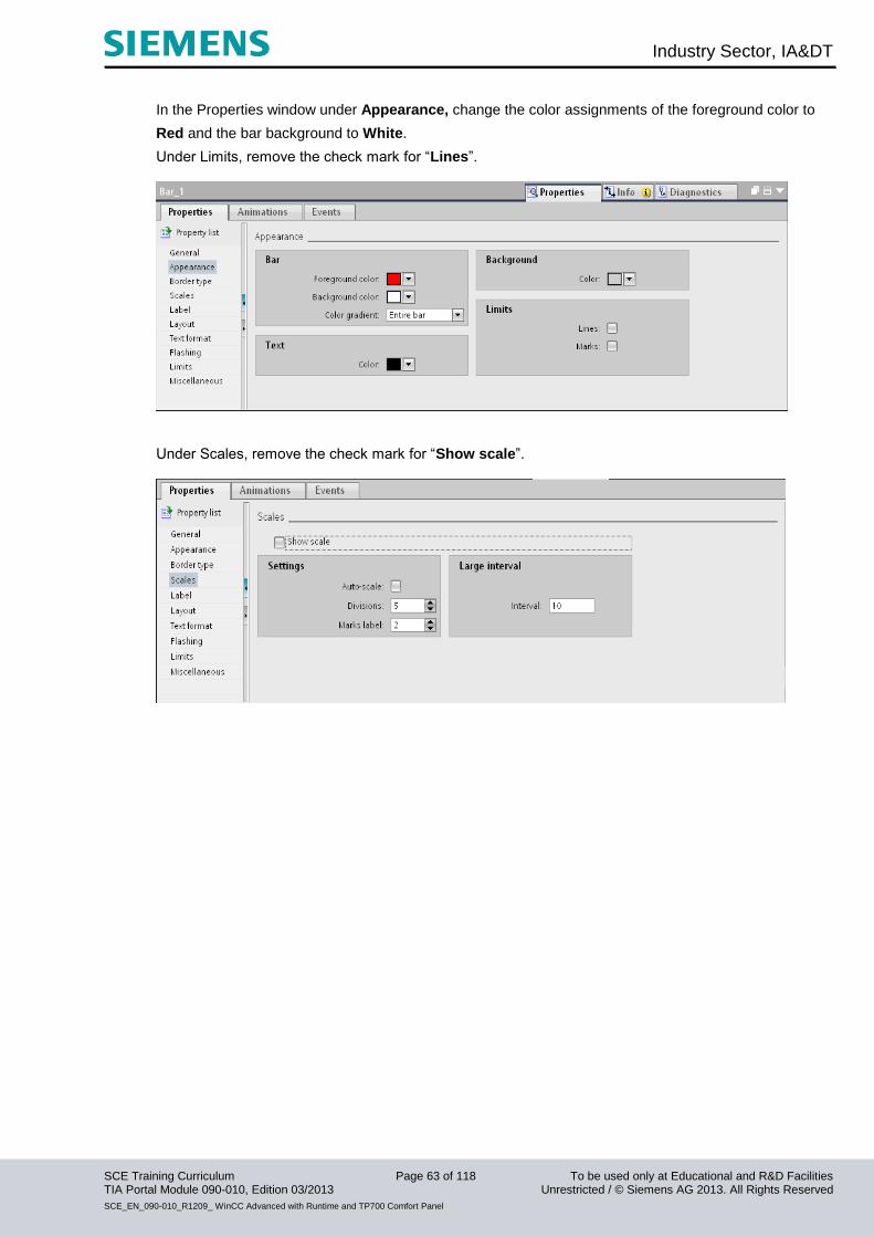
In the Properties window under Appearance, change the color assignments of the foreground color to
Red and the bar background to White.
Under Limits, remove the check mark for “Lines”.
Under Scales, remove the check mark for “Show scale”.
Industry Sector, IA&DT
SCE Training Curriculum Page 64 of 118 To be used only at Educational and R&D Facilities TIA Portal Module 090-010, Edition 03/2013 Unrestricted / © Siemens AG 2013. All Rights Reserved
SCE_EN_090-010_R1209_ WinCC Advanced with Runtime and TP700 Comfort Panel
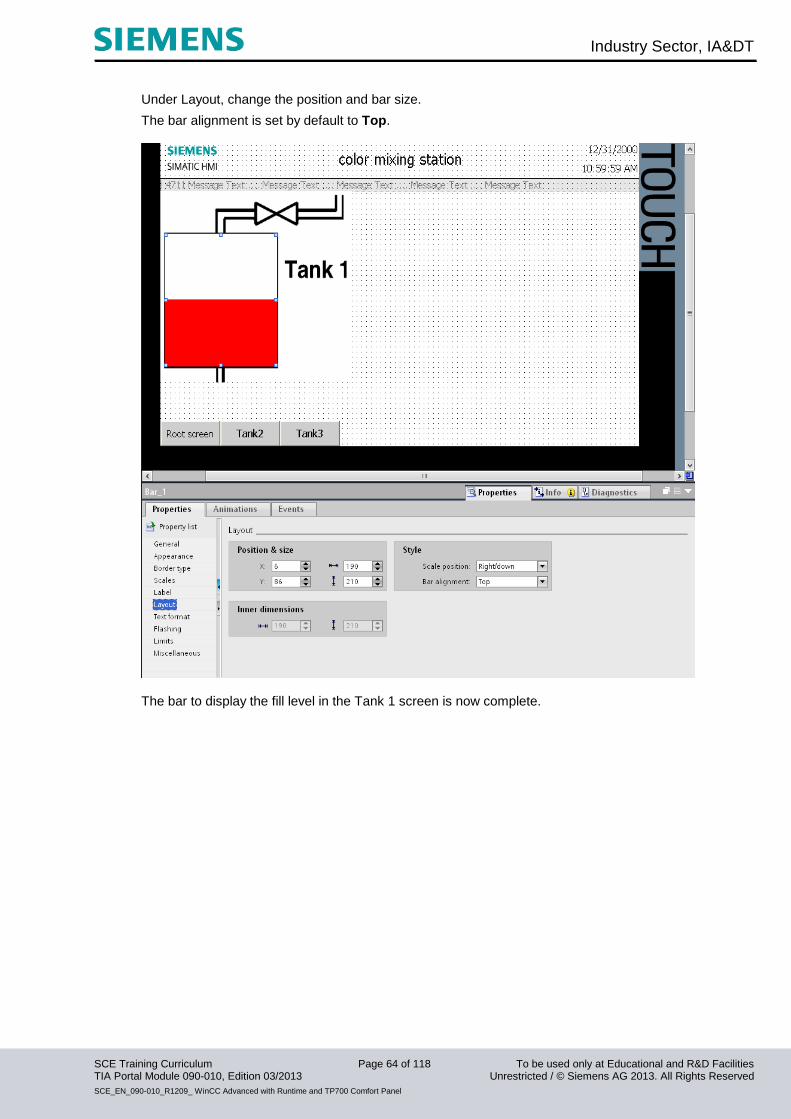
Under Layout, change the position and bar size.
The bar alignment is set by default to Top.
The bar to display the fill level in the Tank 1 screen is now complete.

Industry Sector, IA&DT
SCE Training Curriculum Page 65 of 118 To be used only at Educational and R&D Facilities TIA Portal Module 090-010, Edition 03/2013 Unrestricted / © Siemens AG 2013. All Rights Reserved
SCE_EN_090-010_R1209_ WinCC Advanced with Runtime and TP700 Comfort Panel
Configuring sliders A slider is configured to set the minimum fill level.
From the Tools window, under Enhanced objects, drag the slider to the "Tank 1“ screen.
Enter 450 as maximum value and 10 as minimum value, and select the tag " low_level" as process tag
from the FB call "tank1" of the DB1 of the color mixing station.
Note In WinCC, you can also access the tag declaration in a data block.

Industry Sector, IA&DT
SCE Training Curriculum Page 66 of 118 To be used only at Educational and R&D Facilities TIA Portal Module 090-010, Edition 03/2013 Unrestricted / © Siemens AG 2013. All Rights Reserved
SCE_EN_090-010_R1209_ WinCC Advanced with Runtime and TP700 Comfort Panel
Under General, enter “MIN” as the title.
Under Layout, change the position and size of the slider.
Under Text format, change the font size to Tahoma, 15px bold.
Insert a second slider to set the maximum fill level in Tank 1.
Change the minimum value to 550 and the maximum value to 990, and select the tag “high_level” as
process tag from the FB call “tank1” of the DB1.
Under Layout, enter “MAX” as the title.
Position the slider to X600 and Y80 and change the size to 100 x 260.
Under Text format, change the font size.

Industry Sector, IA&DT
SCE Training Curriculum Page 67 of 118 To be used only at Educational and R&D Facilities TIA Portal Module 090-010, Edition 03/2013 Unrestricted / © Siemens AG 2013. All Rights Reserved
SCE_EN_090-010_R1209_ WinCC Advanced with Runtime and TP700 Comfort Panel
The Tank 1 screen now looks like this.
Three tags have now been created automatically.
Set the acquisition cycle of the newly created tags to 100 ms.
Remember to save the project!
Industry Sector, IA&DT
SCE Training Curriculum Page 68 of 118 To be used only at Educational and R&D Facilities TIA Portal Module 090-010, Edition 03/2013 Unrestricted / © Siemens AG 2013. All Rights Reserved
SCE_EN_090-010_R1209_ WinCC Advanced with Runtime and TP700 Comfort Panel
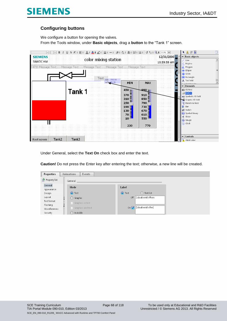
Configuring buttons We configure a button for opening the valves.
From the Tools window, under Basic objects, drag a button to the “Tank 1” screen.
Under General, select the Text On check box and enter the text.
Caution! Do not press the Enter key after entering the text; otherwise, a new line will be created.
Industry Sector, IA&DT
SCE Training Curriculum Page 69 of 118 To be used only at Educational and R&D Facilities TIA Portal Module 090-010, Edition 03/2013 Unrestricted / © Siemens AG 2013. All Rights Reserved
SCE_EN_090-010_R1209_ WinCC Advanced with Runtime and TP700 Comfort Panel
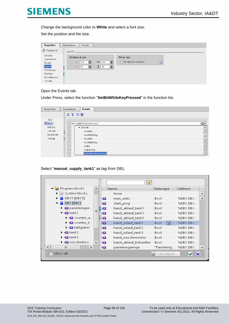
Change the background color to White and select a font size.
Set the position and the size.
Open the Events tab.
Under Press, select the function "SetBitWhileKeyPressed" in the function list.
Select “manual_supply_tank1” as tag from DB1.
Industry Sector, IA&DT
SCE Training Curriculum Page 70 of 118 To be used only at Educational and R&D Facilities TIA Portal Module 090-010, Edition 03/2013 Unrestricted / © Siemens AG 2013. All Rights Reserved
SCE_EN_090-010_R1209_ WinCC Advanced with Runtime and TP700 Comfort Panel
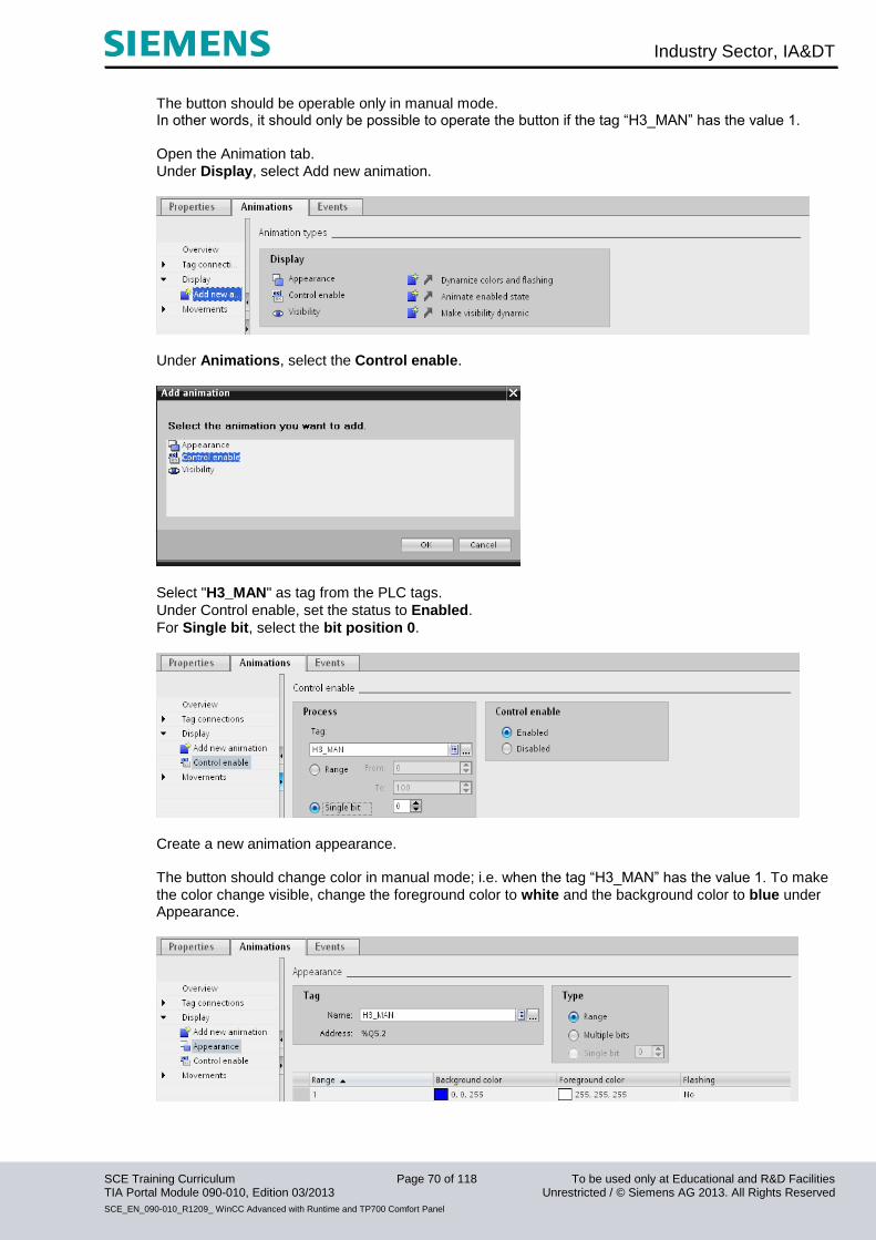
The button should be operable only in manual mode. In other words, it should only be possible to operate the button if the tag “H3_MAN” has the value 1. Open the Animation tab.
Under Display, select Add new animation.
Under Animations, select the Control enable.
Select "H3_MAN" as tag from the PLC tags.
Under Control enable, set the status to Enabled.
For Single bit, select the bit position 0.
Create a new animation appearance. The button should change color in manual mode; i.e. when the tag “H3_MAN” has the value 1. To make
the color change visible, change the foreground color to white and the background color to blue under Appearance.
Industry Sector, IA&DT
SCE Training Curriculum Page 71 of 118 To be used only at Educational and R&D Facilities TIA Portal Module 090-010, Edition 03/2013 Unrestricted / © Siemens AG 2013. All Rights Reserved
SCE_EN_090-010_R1209_ WinCC Advanced with Runtime and TP700 Comfort Panel
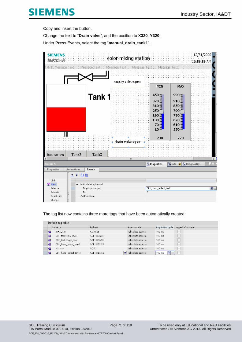
Copy and insert the button.
Change the text to “Drain valve”, and the position to X320, Y320.
Under Press Events, select the tag “manual_drain_tank1”.
The tag list now contains three more tags that have been automatically created.
Industry Sector, IA&DT
SCE Training Curriculum Page 72 of 118 To be used only at Educational and R&D Facilities TIA Portal Module 090-010, Edition 03/2013 Unrestricted / © Siemens AG 2013. All Rights Reserved
SCE_EN_090-010_R1209_ WinCC Advanced with Runtime and TP700 Comfort Panel
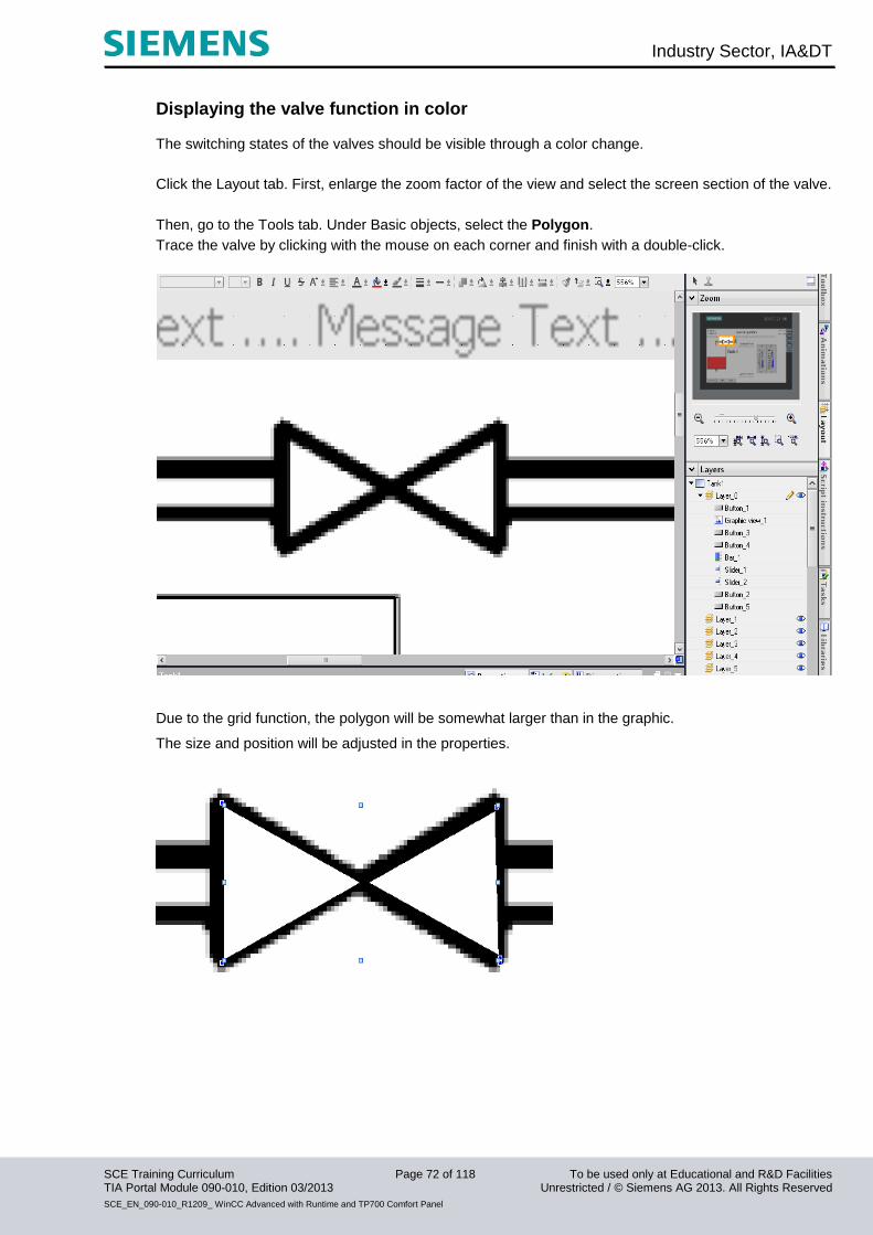
Displaying the valve function in color The switching states of the valves should be visible through a color change.
Click the Layout tab. First, enlarge the zoom factor of the view and select the screen section of the valve.
Then, go to the Tools tab. Under Basic objects, select the Polygon.
Trace the valve by clicking with the mouse on each corner and finish with a double-click.
Due to the grid function, the polygon will be somewhat larger than in the graphic.
The size and position will be adjusted in the properties.
Industry Sector, IA&DT
SCE Training Curriculum Page 73 of 118 To be used only at Educational and R&D Facilities TIA Portal Module 090-010, Edition 03/2013 Unrestricted / © Siemens AG 2013. All Rights Reserved
SCE_EN_090-010_R1209_ WinCC Advanced with Runtime and TP700 Comfort Panel
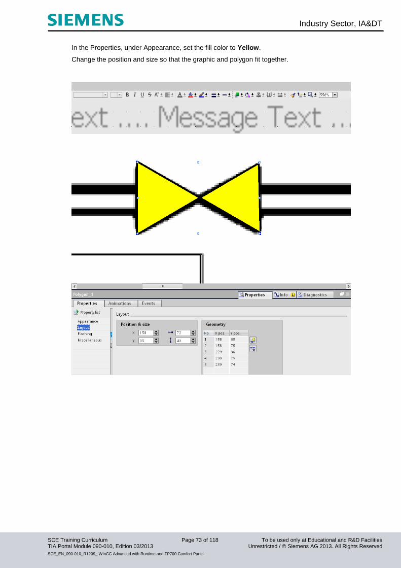
In the Properties, under Appearance, set the fill color to Yellow.
Change the position and size so that the graphic and polygon fit together.

Industry Sector, IA&DT
SCE Training Curriculum Page 74 of 118 To be used only at Educational and R&D Facilities TIA Portal Module 090-010, Edition 03/2013 Unrestricted / © Siemens AG 2013. All Rights Reserved
SCE_EN_090-010_R1209_ WinCC Advanced with Runtime and TP700 Comfort Panel
Create a new animation Appearance and use the tag Supply_T1.
Enter the value 1 as range and change the background color to red.
Copy and insert the polygon. Rotate the polygon by 90 degrees and position it below the tank (button for
rotating by 90 degrees is in the toolbar at the top).
Use the tag “DRAIN_T1” for the color change in the appearance.
The tag list now contains two more tags that have been automatically created.
Remember to save the project!
Industry Sector, IA&DT
SCE Training Curriculum Page 75 of 118 To be used only at Educational and R&D Facilities TIA Portal Module 090-010, Edition 03/2013 Unrestricted / © Siemens AG 2013. All Rights Reserved
SCE_EN_090-010_R1209_ WinCC Advanced with Runtime and TP700 Comfort Panel
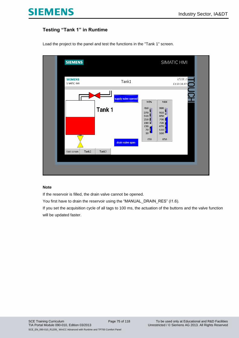
Testing “Tank 1” in Runtime Load the project to the panel and test the functions in the "Tank 1" screen.
Note
If the reservoir is filled, the drain valve cannot be opened.
You first have to drain the reservoir using the “MANUAL_DRAIN_RES” (I1.6).
If you set the acquisition cycle of all tags to 100 ms, the actuation of the buttons and the valve function
will be updated faster.
Industry Sector, IA&DT
SCE Training Curriculum Page 76 of 118 To be used only at Educational and R&D Facilities TIA Portal Module 090-010, Edition 03/2013 Unrestricted / © Siemens AG 2013. All Rights Reserved
SCE_EN_090-010_R1209_ WinCC Advanced with Runtime and TP700 Comfort Panel
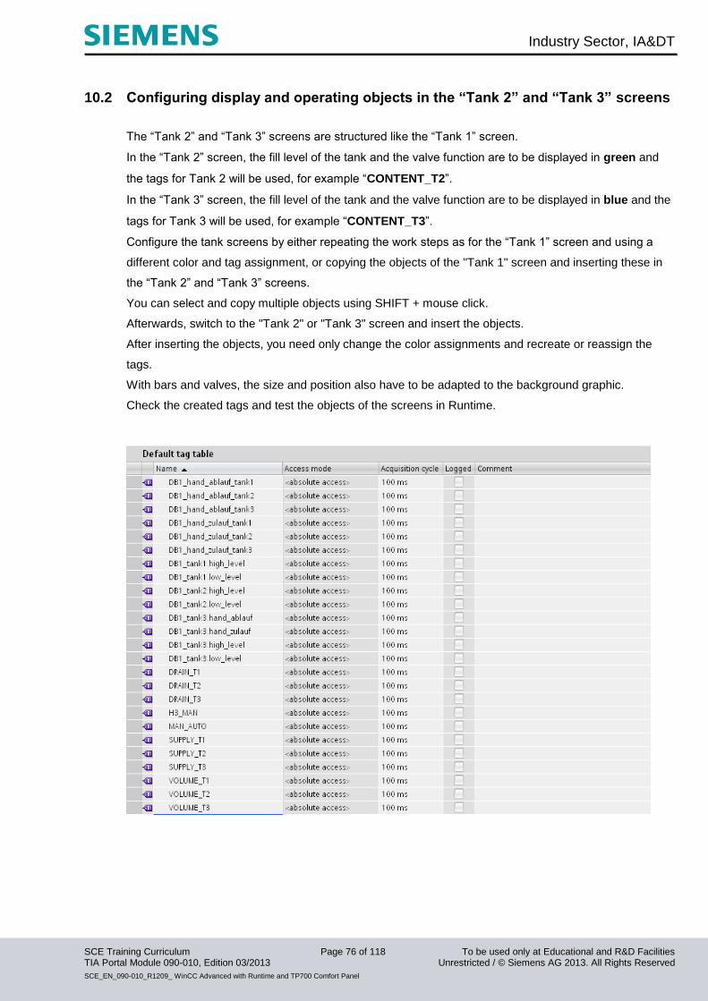
10.2 Configuring display and operating objects in the “Tank 2” and “Tank 3” screens
The “Tank 2” and “Tank 3” screens are structured like the “Tank 1” screen.
In the “Tank 2” screen, the fill level of the tank and the valve function are to be displayed in green and
the tags for Tank 2 will be used, for example “CONTENT_T2”.
In the “Tank 3” screen, the fill level of the tank and the valve function are to be displayed in blue and the
tags for Tank 3 will be used, for example “CONTENT_T3”.
Configure the tank screens by either repeating the work steps as for the “Tank 1” screen and using a
different color and tag assignment, or copying the objects of the "Tank 1" screen and inserting these in
the “Tank 2” and “Tank 3” screens.
You can select and copy multiple objects using SHIFT + mouse click.
Afterwards, switch to the "Tank 2" or "Tank 3" screen and insert the objects.
After inserting the objects, you need only change the color assignments and recreate or reassign the
tags.
With bars and valves, the size and position also have to be adapted to the background graphic.
Check the created tags and test the objects of the screens in Runtime.

Industry Sector, IA&DT
SCE Training Curriculum Page 77 of 118 To be used only at Educational and R&D Facilities TIA Portal Module 090-010, Edition 03/2013 Unrestricted / © Siemens AG 2013. All Rights Reserved
SCE_EN_090-010_R1209_ WinCC Advanced with Runtime and TP700 Comfort Panel
View of “Tank 2” screen
View of “Tank 3” screen
Industry Sector, IA&DT
SCE Training Curriculum Page 78 of 118 To be used only at Educational and R&D Facilities TIA Portal Module 090-010, Edition 03/2013 Unrestricted / © Siemens AG 2013. All Rights Reserved
SCE_EN_090-010_R1209_ WinCC Advanced with Runtime and TP700 Comfort Panel
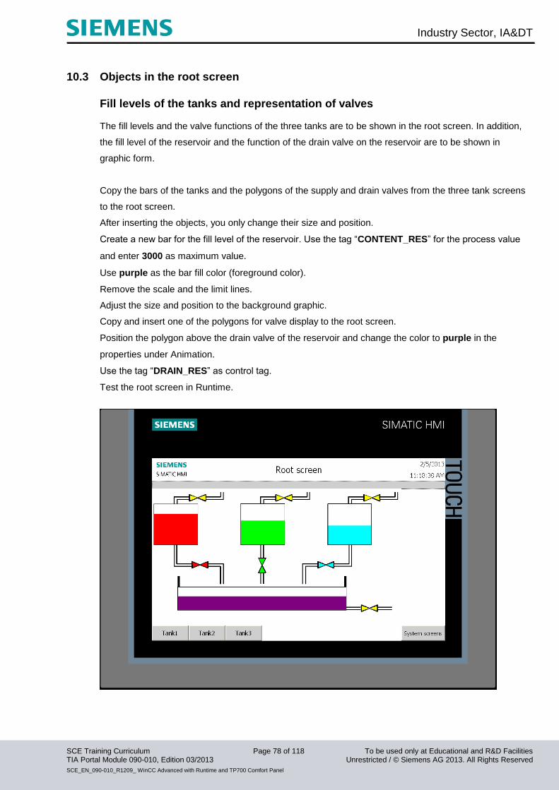
10.3 Objects in the root screen
Fill levels of the tanks and representation of valves The fill levels and the valve functions of the three tanks are to be shown in the root screen. In addition,
the fill level of the reservoir and the function of the drain valve on the reservoir are to be shown in
graphic form.
Copy the bars of the tanks and the polygons of the supply and drain valves from the three tank screens
to the root screen.
After inserting the objects, you only change their size and position.
Create a new bar for the fill level of the reservoir. Use the tag “CONTENT_RES” for the process value
and enter 3000 as maximum value.
Use purple as the bar fill color (foreground color).
Remove the scale and the limit lines.
Adjust the size and position to the background graphic.
Copy and insert one of the polygons for valve display to the root screen.
Position the polygon above the drain valve of the reservoir and change the color to purple in the
properties under Animation.
Use the tag “DRAIN_RES” as control tag.
Test the root screen in Runtime.

Industry Sector, IA&DT
SCE Training Curriculum Page 79 of 118 To be used only at Educational and R&D Facilities TIA Portal Module 090-010, Edition 03/2013 Unrestricted / © Siemens AG 2013. All Rights Reserved
SCE_EN_090-010_R1209_ WinCC Advanced with Runtime and TP700 Comfort Panel
Configuring the mixer motor A graphic I/O field that is connected to a graphics list is used to display the mixer motor.
A symbolic I/O field connected to a text list is used for manual operation via the panel.
Creating a graphics list
Double-click Graphic lists in the “Text and graphic lists” folder in the project window.
Double-click in the Name column in the first row to create a new graphics list.
Change the name of the graphics list to "Motor".
Under Selection, select "Range (… - …)" or "Bit (0, 1)".
Below, insert the graphic "motor_off" at Value 0 and the graphic "motor_on“ at value 1 from the
screens template directory.
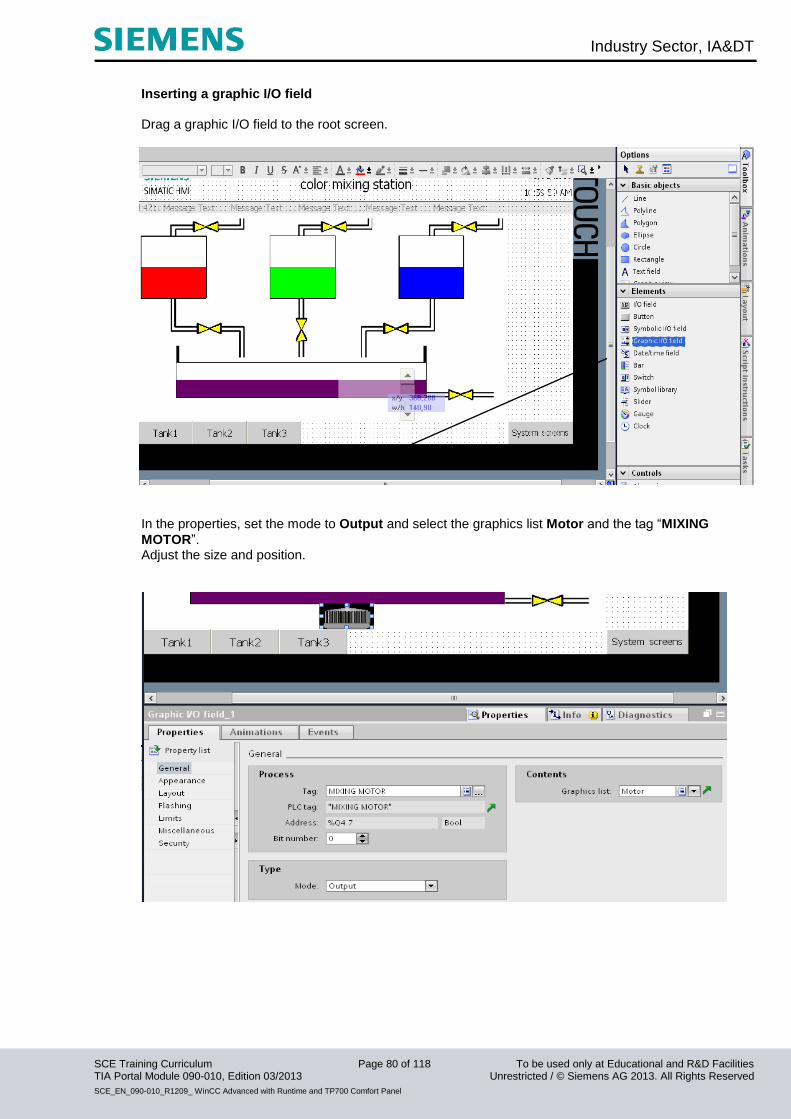
Industry Sector, IA&DT
SCE Training Curriculum Page 80 of 118 To be used only at Educational and R&D Facilities TIA Portal Module 090-010, Edition 03/2013 Unrestricted / © Siemens AG 2013. All Rights Reserved
SCE_EN_090-010_R1209_ WinCC Advanced with Runtime and TP700 Comfort Panel
Inserting a graphic I/O field Drag a graphic I/O field to the root screen.
In the properties, set the mode to Output and select the graphics list Motor and the tag “MIXING
MOTOR”. Adjust the size and position.
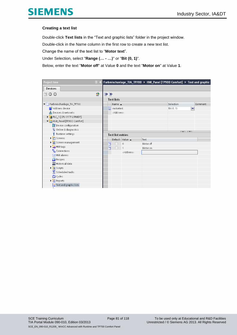
Industry Sector, IA&DT
SCE Training Curriculum Page 81 of 118 To be used only at Educational and R&D Facilities TIA Portal Module 090-010, Edition 03/2013 Unrestricted / © Siemens AG 2013. All Rights Reserved
SCE_EN_090-010_R1209_ WinCC Advanced with Runtime and TP700 Comfort Panel
Creating a text list
Double-click Text lists in the “Text and graphic lists” folder in the project window.
Double-click in the Name column in the first row to create a new text list.
Change the name of the text list to “Motor text”.
Under Selection, select "Range (… - …)" or "Bit (0, 1)".
Below, enter the text "Motor off" at Value 0 and the text "Motor on" at Value 1.

Industry Sector, IA&DT
SCE Training Curriculum Page 82 of 118 To be used only at Educational and R&D Facilities TIA Portal Module 090-010, Edition 03/2013 Unrestricted / © Siemens AG 2013. All Rights Reserved
SCE_EN_090-010_R1209_ WinCC Advanced with Runtime and TP700 Comfort Panel
Inserting a symbolic I/O field Drag a symbolic I/O field to the root screen.
Set mode to Input/output and select the text list Motor text and the tag "manual_mixing motor".
Adjust the font size, size and position.
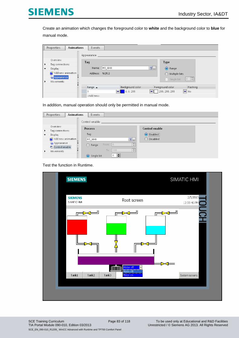
Industry Sector, IA&DT
SCE Training Curriculum Page 83 of 118 To be used only at Educational and R&D Facilities TIA Portal Module 090-010, Edition 03/2013 Unrestricted / © Siemens AG 2013. All Rights Reserved
SCE_EN_090-010_R1209_ WinCC Advanced with Runtime and TP700 Comfort Panel
Create an animation which changes the foreground color to white and the background color to blue for
manual mode.
In addition, manual operation should only be permitted in manual mode.
Test the function in Runtime.

Industry Sector, IA&DT
SCE Training Curriculum Page 84 of 118 To be used only at Educational and R&D Facilities TIA Portal Module 090-010, Edition 03/2013 Unrestricted / © Siemens AG 2013. All Rights Reserved
SCE_EN_090-010_R1209_ WinCC Advanced with Runtime and TP700 Comfort Panel
Configuring manual mode for the drain valve of the reservoir We configure an additional button for opening the drain valve.
From the Tools window, under Elements, drag a button to the root screen.
Under General, for Text OFF, enter "drain open". Select the Text ON check box and enter the text
"drain open".
Caution! Do not press the Enter key after entering the text; otherwise, a new line will be created.
Set the position and the size.
Under Press, select the function “SetBitWhileKeyPressed” in the function list.
Select “manual_drain_reservoir” as tag from DB1.
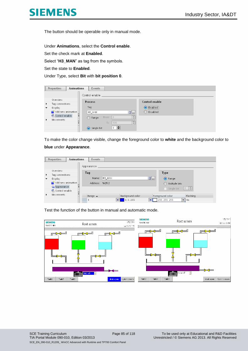
Industry Sector, IA&DT
SCE Training Curriculum Page 85 of 118 To be used only at Educational and R&D Facilities TIA Portal Module 090-010, Edition 03/2013 Unrestricted / © Siemens AG 2013. All Rights Reserved
SCE_EN_090-010_R1209_ WinCC Advanced with Runtime and TP700 Comfort Panel
The button should be operable only in manual mode.
Under Animations, select the Control enable.
Set the check mark at Enabled.
Select “H3_MAN” as tag from the symbols.
Set the state to Enabled.
Under Type, select Bit with bit position 0.
To make the color change visible, change the foreground color to white and the background color to
blue under Appearance.
Test the function of the button in manual and automatic mode.

Industry Sector, IA&DT
SCE Training Curriculum Page 86 of 118 To be used only at Educational and R&D Facilities TIA Portal Module 090-010, Edition 03/2013 Unrestricted / © Siemens AG 2013. All Rights Reserved
SCE_EN_090-010_R1209_ WinCC Advanced with Runtime and TP700 Comfort Panel
Switching the operating mode It should be possible to select the operating mode on the TP700 Panel as well.
A switch is used for this function. Drag a switch to the root screen.
Under Settings, select the switch with text and enter the text.
Use “man_auto” from DB1 as the tag.

Industry Sector, IA&DT
SCE Training Curriculum Page 87 of 118 To be used only at Educational and R&D Facilities TIA Portal Module 090-010, Edition 03/2013 Unrestricted / © Siemens AG 2013. All Rights Reserved
SCE_EN_090-010_R1209_ WinCC Advanced with Runtime and TP700 Comfort Panel
In the properties, change the text color to white and the background color to blue under Appearance;
under Text format, select a smaller font size. Set the position and the size under Layout.
Under Appearance, select the tag “H2_AUTO” from the symbol table.
In addition, change the foreground color to black and the background color to green.
Test the manual/automatic switchover in Runtime.
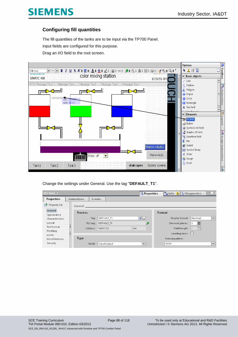
Industry Sector, IA&DT
SCE Training Curriculum Page 88 of 118 To be used only at Educational and R&D Facilities TIA Portal Module 090-010, Edition 03/2013 Unrestricted / © Siemens AG 2013. All Rights Reserved
SCE_EN_090-010_R1209_ WinCC Advanced with Runtime and TP700 Comfort Panel
Configuring fill quantities The fill quantities of the tanks are to be input via the TP700 Panel.
Input fields are configured for this purpose.
Drag an I/O field to the root screen.
Change the settings under General. Use the tag "DEFAULT_T1".

Industry Sector, IA&DT
SCE Training Curriculum Page 89 of 118 To be used only at Educational and R&D Facilities TIA Portal Module 090-010, Edition 03/2013 Unrestricted / © Siemens AG 2013. All Rights Reserved
SCE_EN_090-010_R1209_ WinCC Advanced with Runtime and TP700 Comfort Panel
Change the properties under Layout.
Change the properties under Text format.
Copy and paste the I/O field. Position it once beside Tank 2 at X380 and once beside Tank 3 at X620.
Change the tags to DEFAULT_T2 and DEFAULT_T3.

Industry Sector, IA&DT
SCE Training Curriculum Page 90 of 118 To be used only at Educational and R&D Facilities TIA Portal Module 090-010, Edition 03/2013 Unrestricted / © Siemens AG 2013. All Rights Reserved
SCE_EN_090-010_R1209_ WinCC Advanced with Runtime and TP700 Comfort Panel
Configuring the “START” button A “START” button is required to start the color mixing station.
The start button should flash green when the start function is enabled by the program.
It should only be possible to operate the start button if the start function has been enabled.
From the Tools window, under Elements, drag a button to the root screen.
Under General, for Text OFF, enter "START".
Change the background color to white and select a larger font size.
Set the position X680, Y280 and the size 120 x 40.
Under Press, select the function “SetBitWhileKeyPressed” as event.
Select “start_prog” as tag from DB1.
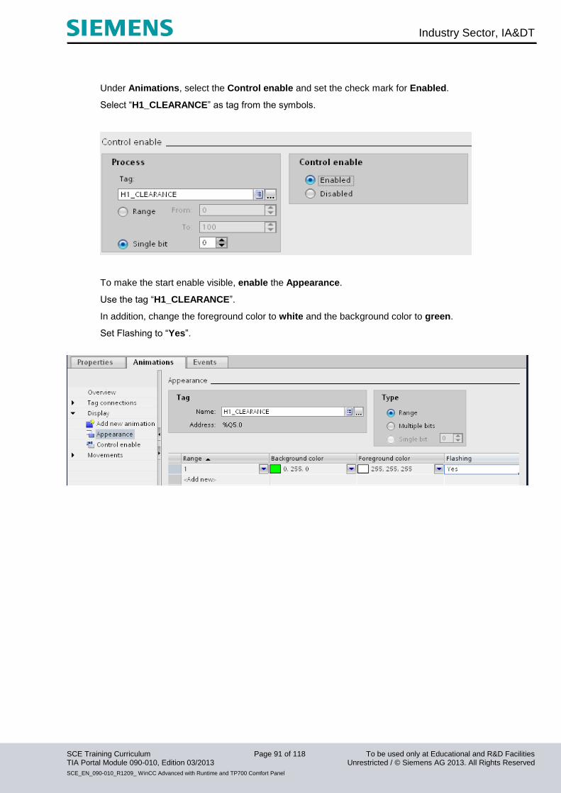
Industry Sector, IA&DT
SCE Training Curriculum Page 91 of 118 To be used only at Educational and R&D Facilities TIA Portal Module 090-010, Edition 03/2013 Unrestricted / © Siemens AG 2013. All Rights Reserved
SCE_EN_090-010_R1209_ WinCC Advanced with Runtime and TP700 Comfort Panel
Under Animations, select the Control enable and set the check mark for Enabled.
Select “H1_CLEARANCE” as tag from the symbols.
To make the start enable visible, enable the Appearance.
Use the tag “H1_CLEARANCE”.
In addition, change the foreground color to white and the background color to green.
Set Flashing to “Yes”.
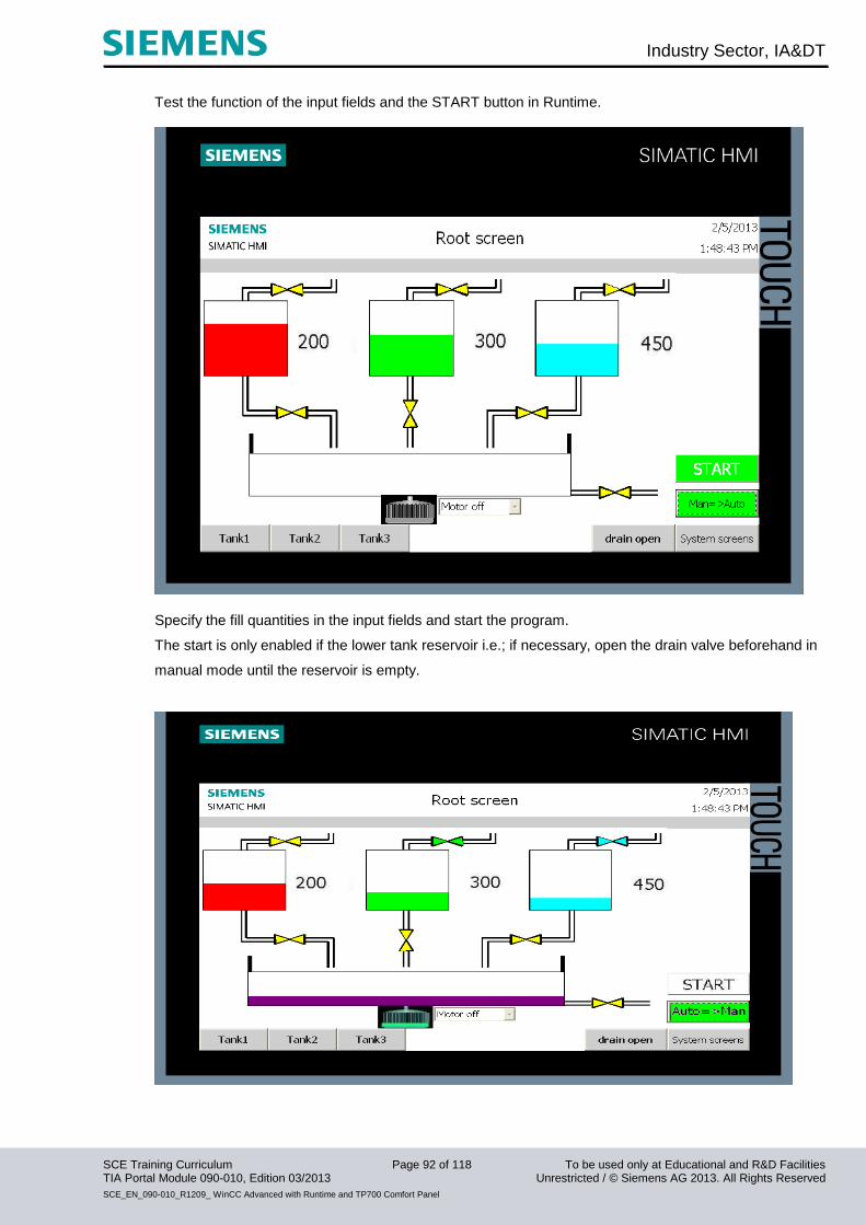
Industry Sector, IA&DT
SCE Training Curriculum Page 92 of 118 To be used only at Educational and R&D Facilities TIA Portal Module 090-010, Edition 03/2013 Unrestricted / © Siemens AG 2013. All Rights Reserved
SCE_EN_090-010_R1209_ WinCC Advanced with Runtime and TP700 Comfort Panel
Test the function of the input fields and the START button in Runtime.
Specify the fill quantities in the input fields and start the program.
The start is only enabled if the lower tank reservoir i.e.; if necessary, open the drain valve beforehand in
manual mode until the reservoir is empty.
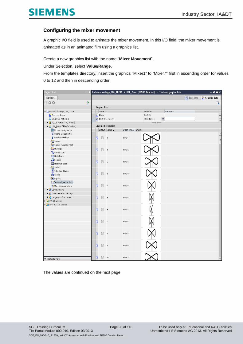
Industry Sector, IA&DT
SCE Training Curriculum Page 93 of 118 To be used only at Educational and R&D Facilities TIA Portal Module 090-010, Edition 03/2013 Unrestricted / © Siemens AG 2013. All Rights Reserved
SCE_EN_090-010_R1209_ WinCC Advanced with Runtime and TP700 Comfort Panel
Configuring the mixer movement A graphic I/O field is used to animate the mixer movement. In this I/O field, the mixer movement is
animated as in an animated film using a graphics list.
Create a new graphics list with the name “Mixer Movement”.
Under Selection, select Value/Range.
From the templates directory, insert the graphics "Mixer1" to "Mixer7" first in ascending order for values
0 to 12 and then in descending order.
The values are continued on the next page
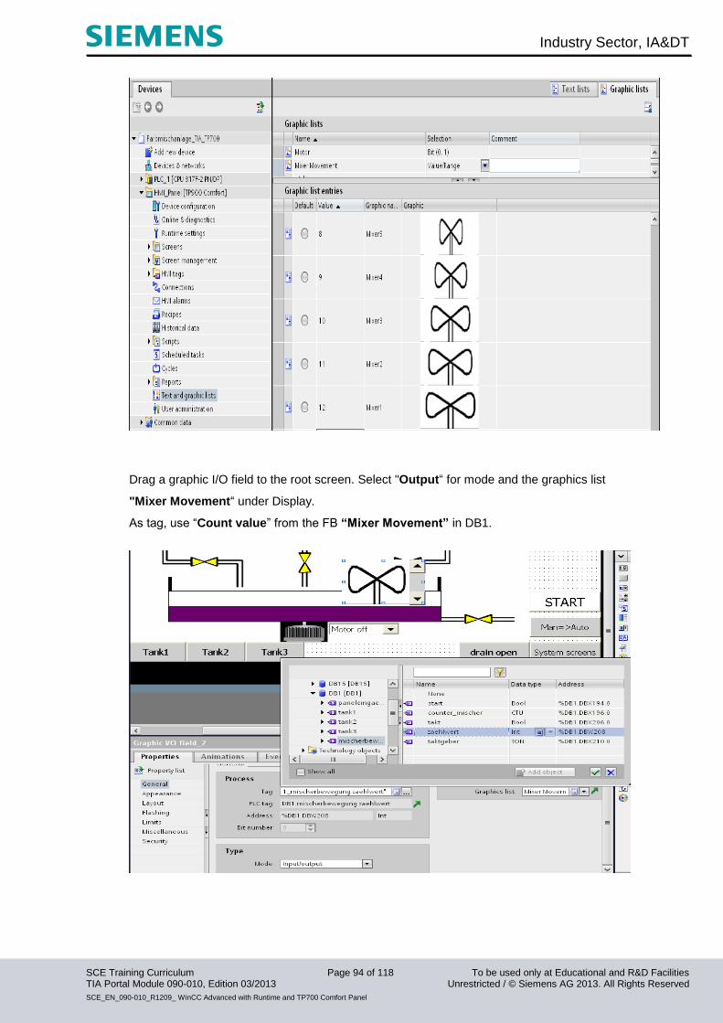
Industry Sector, IA&DT
SCE Training Curriculum Page 94 of 118 To be used only at Educational and R&D Facilities TIA Portal Module 090-010, Edition 03/2013 Unrestricted / © Siemens AG 2013. All Rights Reserved
SCE_EN_090-010_R1209_ WinCC Advanced with Runtime and TP700 Comfort Panel
Drag a graphic I/O field to the root screen. Select "Output“ for mode and the graphics list
"Mixer Movement“ under Display.
As tag, use “Count value” from the FB “Mixer Movement” in DB1.
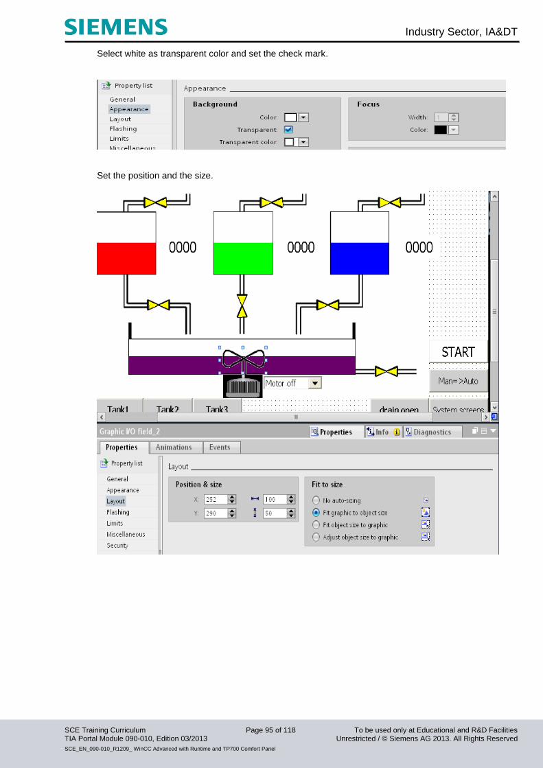
Industry Sector, IA&DT
SCE Training Curriculum Page 95 of 118 To be used only at Educational and R&D Facilities TIA Portal Module 090-010, Edition 03/2013 Unrestricted / © Siemens AG 2013. All Rights Reserved
SCE_EN_090-010_R1209_ WinCC Advanced with Runtime and TP700 Comfort Panel
Select white as transparent color and set the check mark.
Set the position and the size.
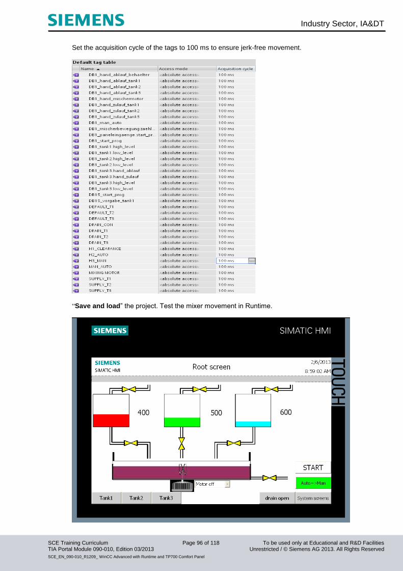
Industry Sector, IA&DT
SCE Training Curriculum Page 96 of 118 To be used only at Educational and R&D Facilities TIA Portal Module 090-010, Edition 03/2013 Unrestricted / © Siemens AG 2013. All Rights Reserved
SCE_EN_090-010_R1209_ WinCC Advanced with Runtime and TP700 Comfort Panel
Set the acquisition cycle of the tags to 100 ms to ensure jerk-free movement.
“Save and load” the project. Test the mixer movement in Runtime.

Industry Sector, IA&DT
SCE Training Curriculum Page 97 of 118 To be used only at Educational and R&D Facilities TIA Portal Module 090-010, Edition 03/2013 Unrestricted / © Siemens AG 2013. All Rights Reserved
SCE_EN_090-010_R1209_ WinCC Advanced with Runtime and TP700 Comfort Panel
10.4 Configuring objects in the permanent window
The permanent window is used to display the fill levels of the three tanks and the reservoir.
Configuring text fields Drag a text field to the permanent window of the root screen.
Enter "Tank 1:" as text.
Set the fill style to transparent.
Set the position and the size.
Select the font size and change the text alignment.
Copy and paste the text field. Change the text and position the text field in such a way that another
output field with the size 80 x 30 fits to the right of it.
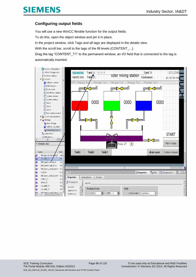
Industry Sector, IA&DT
SCE Training Curriculum Page 98 of 118 To be used only at Educational and R&D Facilities TIA Portal Module 090-010, Edition 03/2013 Unrestricted / © Siemens AG 2013. All Rights Reserved
SCE_EN_090-010_R1209_ WinCC Advanced with Runtime and TP700 Comfort Panel
Configuring output fields You will use a new WinCC flexible function for the output fields.
To do this, open the object window and pin it in place.
In the project window, click Tags and all tags are displayed in the details view.
With the scroll bar, scroll to the tags of the fill levels (CONTENT_...).
Drag the tag “CONTENT_T1” to the permanent window; an I/O field that is connected to the tag is
automatically inserted.

Industry Sector, IA&DT
SCE Training Curriculum Page 99 of 118 To be used only at Educational and R&D Facilities TIA Portal Module 090-010, Edition 03/2013 Unrestricted / © Siemens AG 2013. All Rights Reserved
SCE_EN_090-010_R1209_ WinCC Advanced with Runtime and TP700 Comfort Panel
Set the properties.

Industry Sector, IA&DT
SCE Training Curriculum Page 100 of 118 To be used only at Educational and R&D Facilities TIA Portal Module 090-010, Edition 03/2013 Unrestricted / © Siemens AG 2013. All Rights Reserved
SCE_EN_090-010_R1209_ WinCC Advanced with Runtime and TP700 Comfort Panel
Drag the tags of the other fill levels from the object window to the permanent window and change the
properties, or copy and paste the I/O field and change the tag and the position in the properties.
Save and load the project.
Test the objects in the permanent window in Runtime. Switch to the tank screens as well.
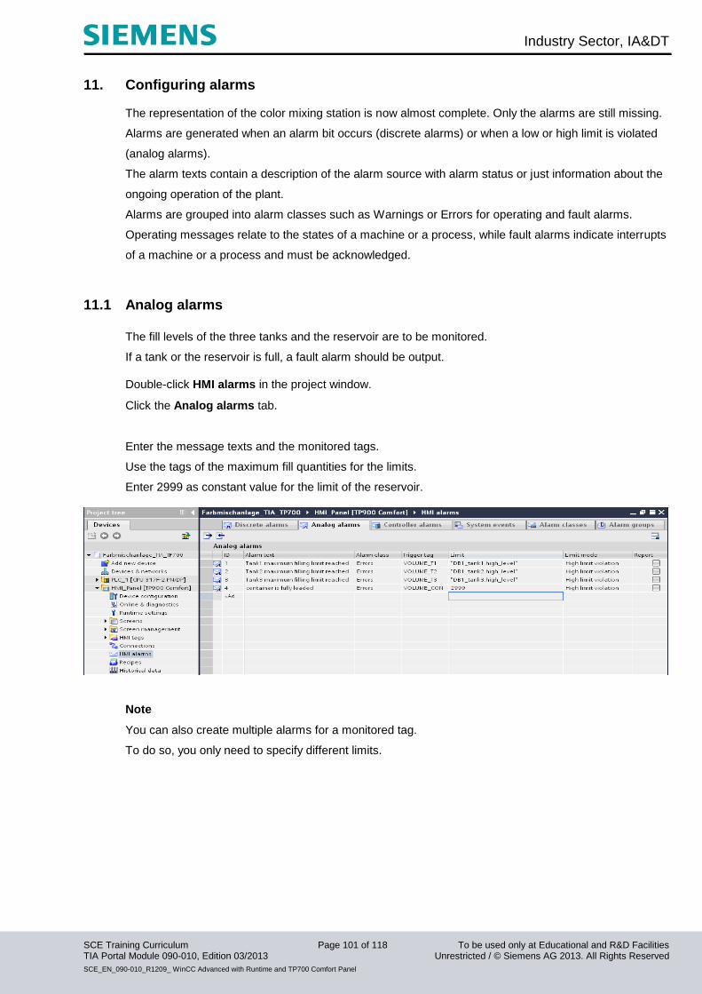
Industry Sector, IA&DT
SCE Training Curriculum Page 101 of 118 To be used only at Educational and R&D Facilities TIA Portal Module 090-010, Edition 03/2013 Unrestricted / © Siemens AG 2013. All Rights Reserved
SCE_EN_090-010_R1209_ WinCC Advanced with Runtime and TP700 Comfort Panel
11. Configuring alarms The representation of the color mixing station is now almost complete. Only the alarms are still missing.
Alarms are generated when an alarm bit occurs (discrete alarms) or when a low or high limit is violated
(analog alarms).
The alarm texts contain a description of the alarm source with alarm status or just information about the
ongoing operation of the plant.
Alarms are grouped into alarm classes such as Warnings or Errors for operating and fault alarms.
Operating messages relate to the states of a machine or a process, while fault alarms indicate interrupts
of a machine or a process and must be acknowledged.
11.1 Analog alarms
The fill levels of the three tanks and the reservoir are to be monitored.
If a tank or the reservoir is full, a fault alarm should be output.
Double-click HMI alarms in the project window.
Click the Analog alarms tab.
Enter the message texts and the monitored tags.
Use the tags of the maximum fill quantities for the limits.
Enter 2999 as constant value for the limit of the reservoir.
Note
You can also create multiple alarms for a monitored tag.
To do so, you only need to specify different limits.
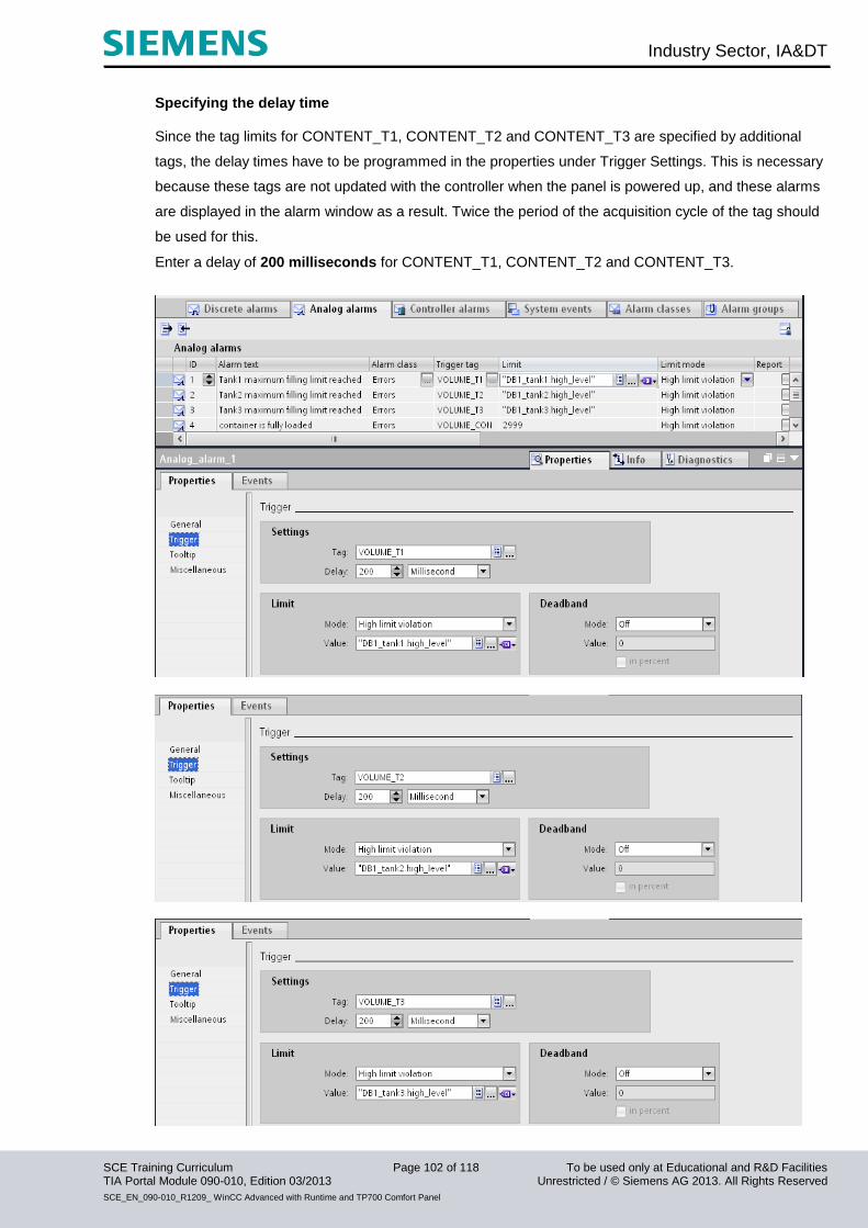
Industry Sector, IA&DT
SCE Training Curriculum Page 102 of 118 To be used only at Educational and R&D Facilities TIA Portal Module 090-010, Edition 03/2013 Unrestricted / © Siemens AG 2013. All Rights Reserved
SCE_EN_090-010_R1209_ WinCC Advanced with Runtime and TP700 Comfort Panel
Specifying the delay time Since the tag limits for CONTENT_T1, CONTENT_T2 and CONTENT_T3 are specified by additional
tags, the delay times have to be programmed in the properties under Trigger Settings. This is necessary
because these tags are not updated with the controller when the panel is powered up, and these alarms
are displayed in the alarm window as a result. Twice the period of the acquisition cycle of the tag should
be used for this.
Enter a delay of 200 milliseconds for CONTENT_T1, CONTENT_T2 and CONTENT_T3.
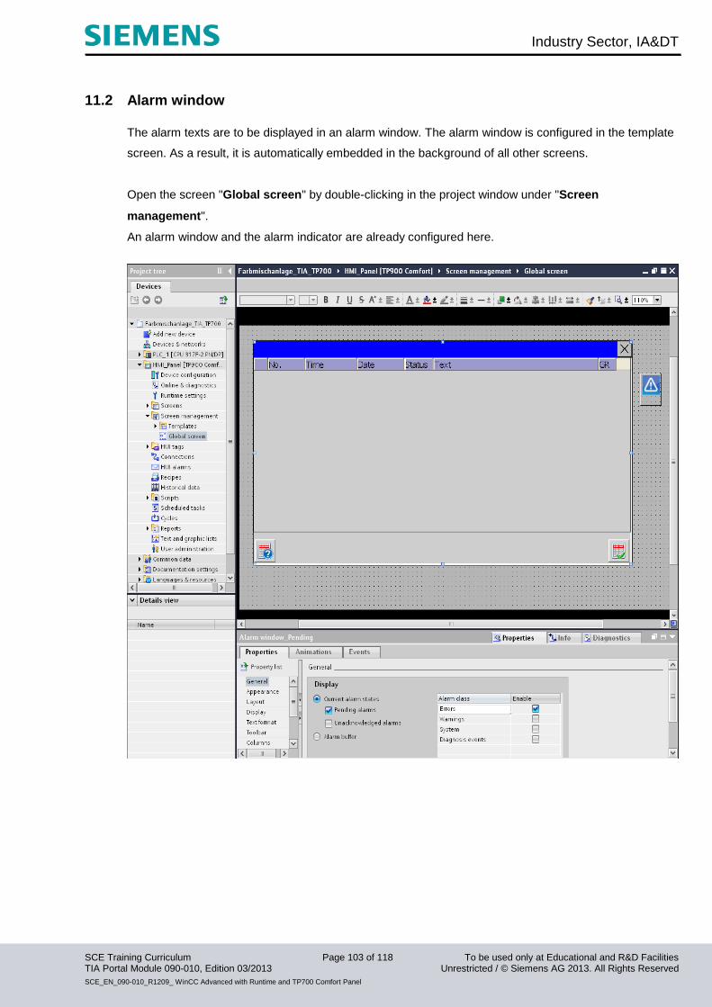
Industry Sector, IA&DT
SCE Training Curriculum Page 103 of 118 To be used only at Educational and R&D Facilities TIA Portal Module 090-010, Edition 03/2013 Unrestricted / © Siemens AG 2013. All Rights Reserved
SCE_EN_090-010_R1209_ WinCC Advanced with Runtime and TP700 Comfort Panel
11.2 Alarm window
The alarm texts are to be displayed in an alarm window. The alarm window is configured in the template
screen. As a result, it is automatically embedded in the background of all other screens.
Open the screen "Global screen" by double-clicking in the project window under "Screen
management".
An alarm window and the alarm indicator are already configured here.
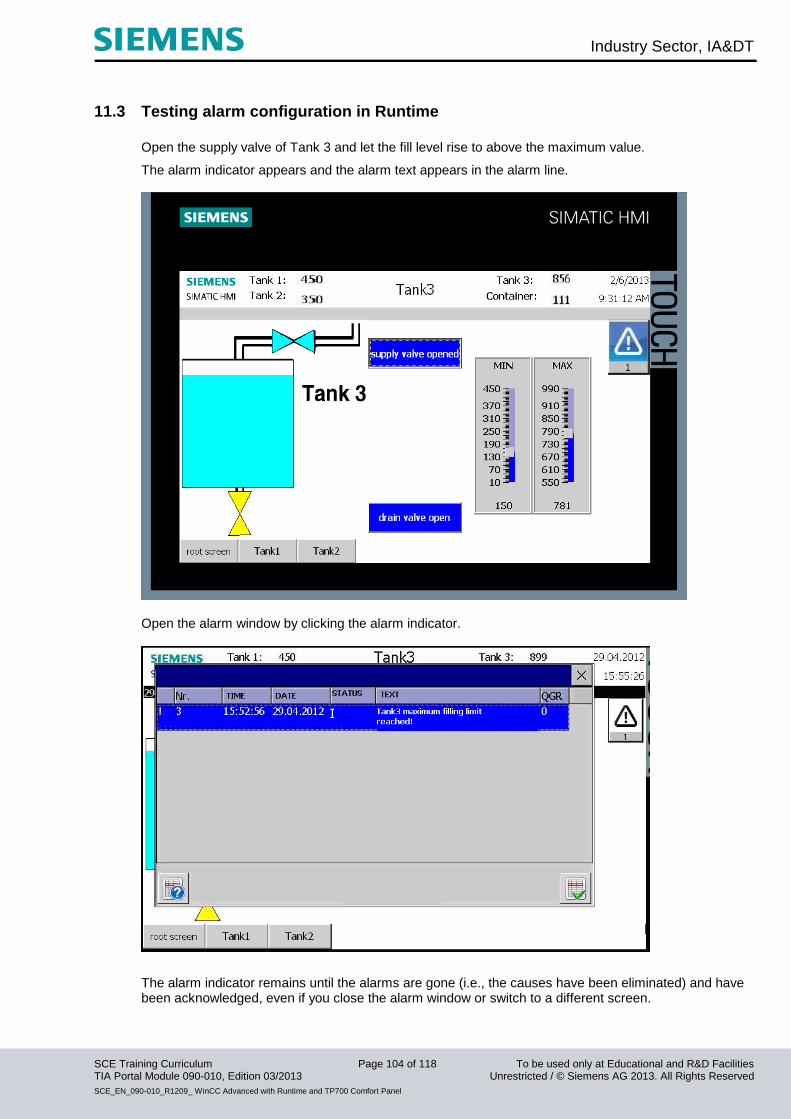
Industry Sector, IA&DT
SCE Training Curriculum Page 104 of 118 To be used only at Educational and R&D Facilities TIA Portal Module 090-010, Edition 03/2013 Unrestricted / © Siemens AG 2013. All Rights Reserved
SCE_EN_090-010_R1209_ WinCC Advanced with Runtime and TP700 Comfort Panel
11.3 Testing alarm configuration in Runtime
Open the supply valve of Tank 3 and let the fill level rise to above the maximum value.
The alarm indicator appears and the alarm text appears in the alarm line.
Open the alarm window by clicking the alarm indicator.
The alarm indicator remains until the alarms are gone (i.e., the causes have been eliminated) and have been acknowledged, even if you close the alarm window or switch to a different screen.
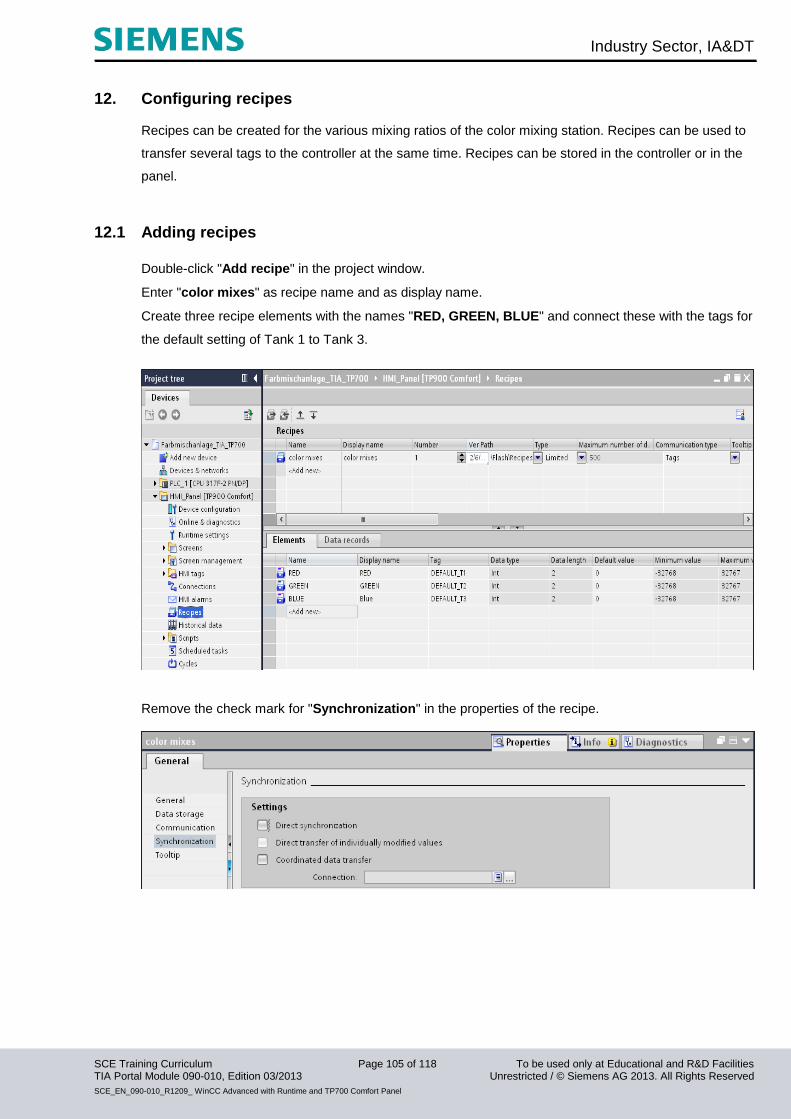
Industry Sector, IA&DT
SCE Training Curriculum Page 105 of 118 To be used only at Educational and R&D Facilities TIA Portal Module 090-010, Edition 03/2013 Unrestricted / © Siemens AG 2013. All Rights Reserved
SCE_EN_090-010_R1209_ WinCC Advanced with Runtime and TP700 Comfort Panel
12. Configuring recipes Recipes can be created for the various mixing ratios of the color mixing station. Recipes can be used to
transfer several tags to the controller at the same time. Recipes can be stored in the controller or in the
panel.
12.1 Adding recipes
Double-click "Add recipe" in the project window.
Enter "color mixes" as recipe name and as display name.
Create three recipe elements with the names "RED, GREEN, BLUE" and connect these with the tags for
the default setting of Tank 1 to Tank 3.
Remove the check mark for "Synchronization" in the properties of the recipe.

Industry Sector, IA&DT
SCE Training Curriculum Page 106 of 118 To be used only at Educational and R&D Facilities TIA Portal Module 090-010, Edition 03/2013 Unrestricted / © Siemens AG 2013. All Rights Reserved
SCE_EN_090-010_R1209_ WinCC Advanced with Runtime and TP700 Comfort Panel
12.2 Specifying data records
Click "Data records" and enter the data records of the “color mixes” recipe.
12.3 Creating "Recipe input" and "Select recipe" screens
Two additional screens have to be created in order to enter and select recipes. A recipe view with freely
definable buttons can thus be used to input new recipes or to make a selection.
Configuring the “Recipe input” screen Create a new screen with the name "Recipe input".
Drag a Recipe view from the Tools window under Controls to the screen.
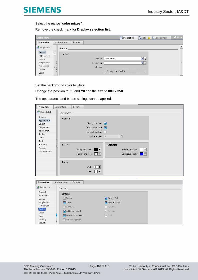
Industry Sector, IA&DT
SCE Training Curriculum Page 107 of 118 To be used only at Educational and R&D Facilities TIA Portal Module 090-010, Edition 03/2013 Unrestricted / © Siemens AG 2013. All Rights Reserved
SCE_EN_090-010_R1209_ WinCC Advanced with Runtime and TP700 Comfort Panel
Select the recipe "color mixes".
Remove the check mark for Display selection list.
Set the background color to white.
Change the position to X0 and Y0 and the size to 800 x 350. The appearance and button settings can be applied.

Industry Sector, IA&DT
SCE Training Curriculum Page 108 of 118 To be used only at Educational and R&D Facilities TIA Portal Module 090-010, Edition 03/2013 Unrestricted / © Siemens AG 2013. All Rights Reserved
SCE_EN_090-010_R1209_ WinCC Advanced with Runtime and TP700 Comfort Panel
Configuring the "Select recipe" screen
Create a new screen with the name "Select recipe". Drag a Recipe view from the Tools window under
Controls to the screen.
Select the recipe "color mixes".
Remove the check mark for Display selection list and for Editing mode.
Set the background color to white.
Change the position to X0 and Y0 and the size to 800 x 350.
Remove all buttons except "Write to PLC" in the recipe view.
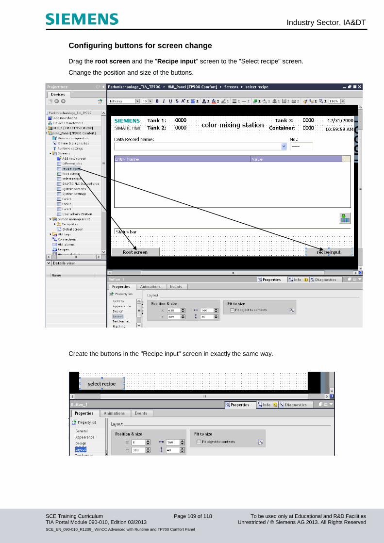
Industry Sector, IA&DT
SCE Training Curriculum Page 109 of 118 To be used only at Educational and R&D Facilities TIA Portal Module 090-010, Edition 03/2013 Unrestricted / © Siemens AG 2013. All Rights Reserved
SCE_EN_090-010_R1209_ WinCC Advanced with Runtime and TP700 Comfort Panel
Configuring buttons for screen change
Drag the root screen and the "Recipe input" screen to the "Select recipe" screen.
Change the position and size of the buttons.
Create the buttons in the "Recipe input" screen in exactly the same way.
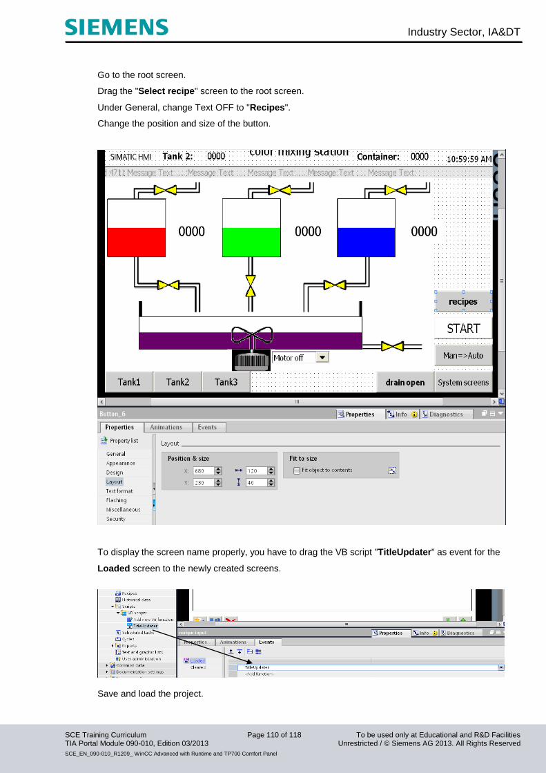
Industry Sector, IA&DT
SCE Training Curriculum Page 110 of 118 To be used only at Educational and R&D Facilities TIA Portal Module 090-010, Edition 03/2013 Unrestricted / © Siemens AG 2013. All Rights Reserved
SCE_EN_090-010_R1209_ WinCC Advanced with Runtime and TP700 Comfort Panel
Go to the root screen.
Drag the "Select recipe" screen to the root screen.
Under General, change Text OFF to "Recipes".
Change the position and size of the button.
To display the screen name properly, you have to drag the VB script "TitleUpdater" as event for the
Loaded screen to the newly created screens.
Save and load the project.
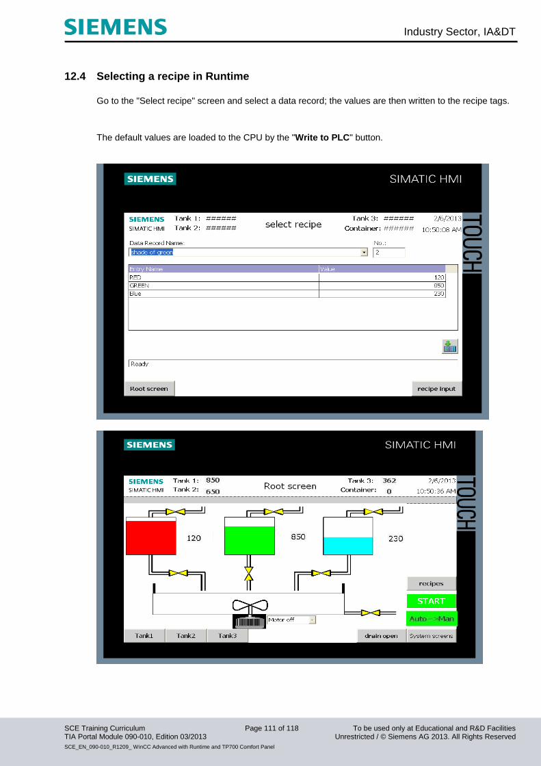
Industry Sector, IA&DT
SCE Training Curriculum Page 111 of 118 To be used only at Educational and R&D Facilities TIA Portal Module 090-010, Edition 03/2013 Unrestricted / © Siemens AG 2013. All Rights Reserved
SCE_EN_090-010_R1209_ WinCC Advanced with Runtime and TP700 Comfort Panel
12.4 Selecting a recipe in Runtime
Go to the "Select recipe" screen and select a data record; the values are then written to the recipe tags.
The default values are loaded to the CPU by the "Write to PLC" button.
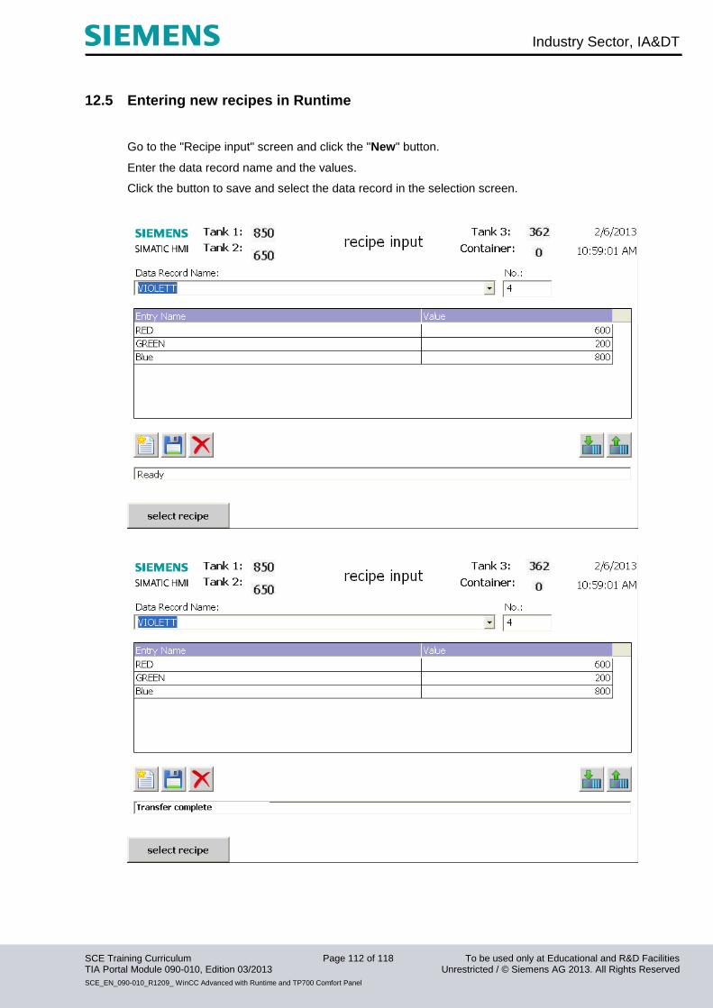
Industry Sector, IA&DT
SCE Training Curriculum Page 112 of 118 To be used only at Educational and R&D Facilities TIA Portal Module 090-010, Edition 03/2013 Unrestricted / © Siemens AG 2013. All Rights Reserved
SCE_EN_090-010_R1209_ WinCC Advanced with Runtime and TP700 Comfort Panel
12.5 Entering new recipes in Runtime
Go to the "Recipe input" screen and click the "New" button.
Enter the data record name and the values.
Click the button to save and select the data record in the selection screen.
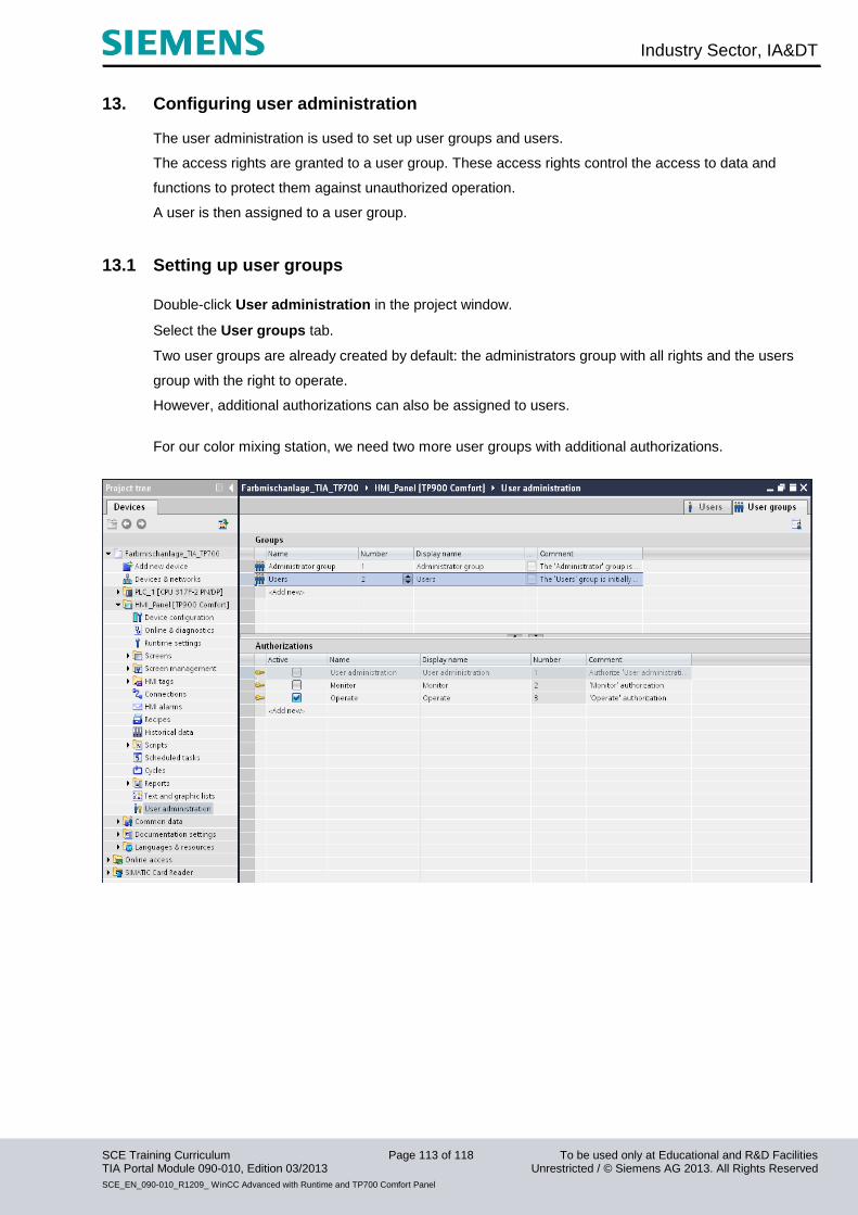
Industry Sector, IA&DT
SCE Training Curriculum Page 113 of 118 To be used only at Educational and R&D Facilities TIA Portal Module 090-010, Edition 03/2013 Unrestricted / © Siemens AG 2013. All Rights Reserved
SCE_EN_090-010_R1209_ WinCC Advanced with Runtime and TP700 Comfort Panel
13. Configuring user administration The user administration is used to set up user groups and users.
The access rights are granted to a user group. These access rights control the access to data and
functions to protect them against unauthorized operation.
A user is then assigned to a user group.
13.1 Setting up user groups
Double-click User administration in the project window.
Select the User groups tab.
Two user groups are already created by default: the administrators group with all rights and the users
group with the right to operate.
However, additional authorizations can also be assigned to users.
For our color mixing station, we need two more user groups with additional authorizations.

Industry Sector, IA&DT
SCE Training Curriculum Page 114 of 118 To be used only at Educational and R&D Facilities TIA Portal Module 090-010, Edition 03/2013 Unrestricted / © Siemens AG 2013. All Rights Reserved
SCE_EN_090-010_R1209_ WinCC Advanced with Runtime and TP700 Comfort Panel
Create the group "Adjuster" with the authorization "switch operation mode".
Create the group "Developer" with the authorization "edit recipes".
13.2 Creating users
Select the Users tab.
We will create three new users here and assign these to user groups.
Create a user with the name "MEIER" and the password "HANS".
Note Note that these entries are case-sensitive.
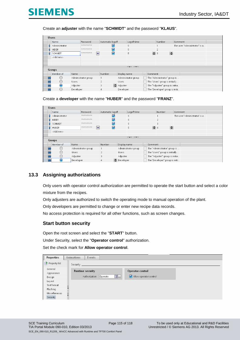
Industry Sector, IA&DT
SCE Training Curriculum Page 115 of 118 To be used only at Educational and R&D Facilities TIA Portal Module 090-010, Edition 03/2013 Unrestricted / © Siemens AG 2013. All Rights Reserved
SCE_EN_090-010_R1209_ WinCC Advanced with Runtime and TP700 Comfort Panel
Create an adjuster with the name "SCHMIDT" and the password "KLAUS".
Create a developer with the name "HUBER" and the password "FRANZ".
13.3 Assigning authorizations
Only users with operator control authorization are permitted to operate the start button and select a color
mixture from the recipes.
Only adjusters are authorized to switch the operating mode to manual operation of the plant.
Only developers are permitted to change or enter new recipe data records.
No access protection is required for all other functions, such as screen changes.
Start button security
Open the root screen and select the "START" button.
Under Security, select the "Operator control" authorization.
Set the check mark for Allow operator control.

Industry Sector, IA&DT
SCE Training Curriculum Page 116 of 118 To be used only at Educational and R&D Facilities TIA Portal Module 090-010, Edition 03/2013 Unrestricted / © Siemens AG 2013. All Rights Reserved
SCE_EN_090-010_R1209_ WinCC Advanced with Runtime and TP700 Comfort Panel
Security of data record selection
In the “Select recipe” screen, select the recipe view and change the security settings.
Security in recipe input
Change the authorization of the recipe view in the “Recipe input” screen to edit recipes.
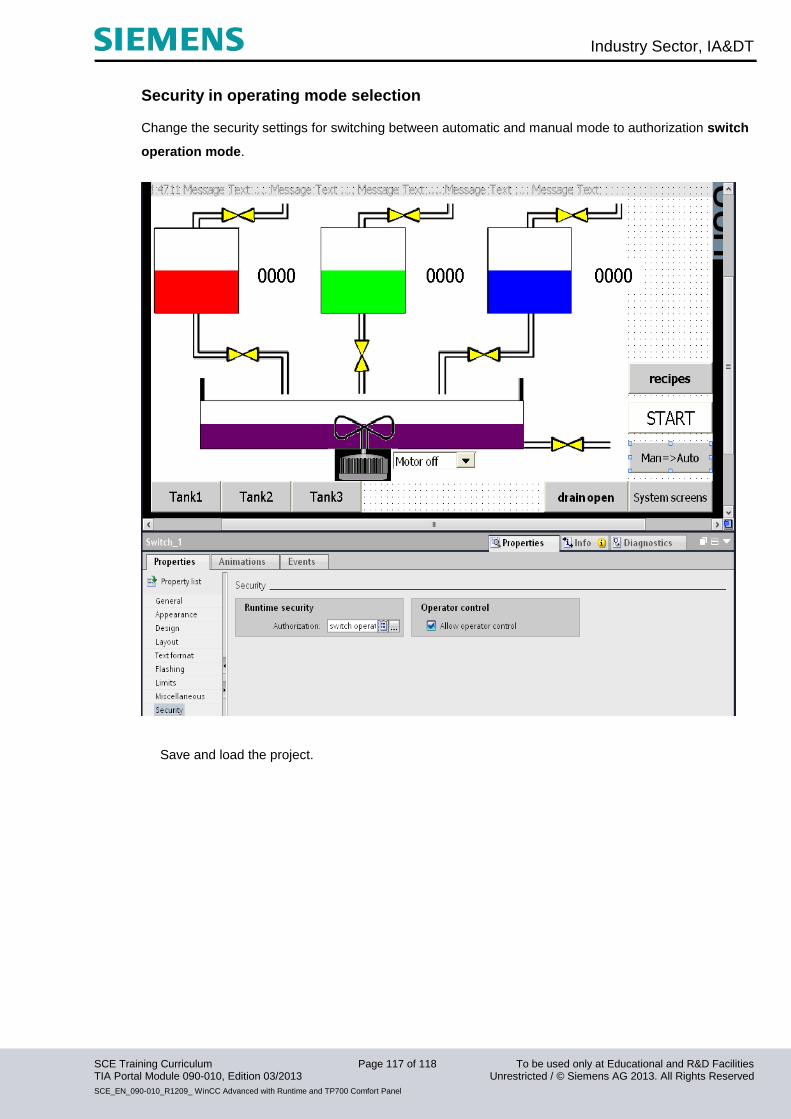
Industry Sector, IA&DT
SCE Training Curriculum Page 117 of 118 To be used only at Educational and R&D Facilities TIA Portal Module 090-010, Edition 03/2013 Unrestricted / © Siemens AG 2013. All Rights Reserved
SCE_EN_090-010_R1209_ WinCC Advanced with Runtime and TP700 Comfort Panel
Security in operating mode selection
Change the security settings for switching between automatic and manual mode to authorization switch
operation mode.
Save and load the project.
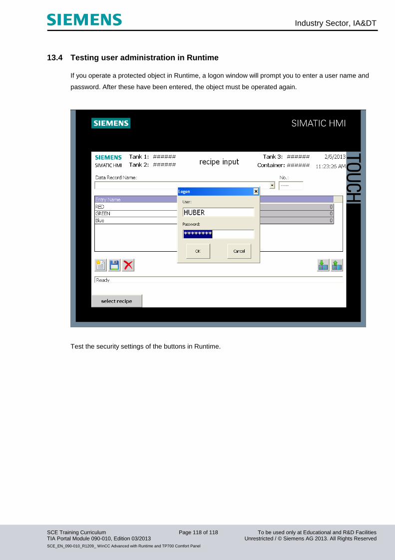
Industry Sector, IA&DT
SCE Training Curriculum Page 118 of 118 To be used only at Educational and R&D Facilities TIA Portal Module 090-010, Edition 03/2013 Unrestricted / © Siemens AG 2013. All Rights Reserved
SCE_EN_090-010_R1209_ WinCC Advanced with Runtime and TP700 Comfort Panel
13.4 Testing user administration in Runtime
If you operate a protected object in Runtime, a logon window will prompt you to enter a user name and
password. After these have been entered, the object must be operated again.
Test the security settings of the buttons in Runtime.