Embed Size (px)
Citation preview
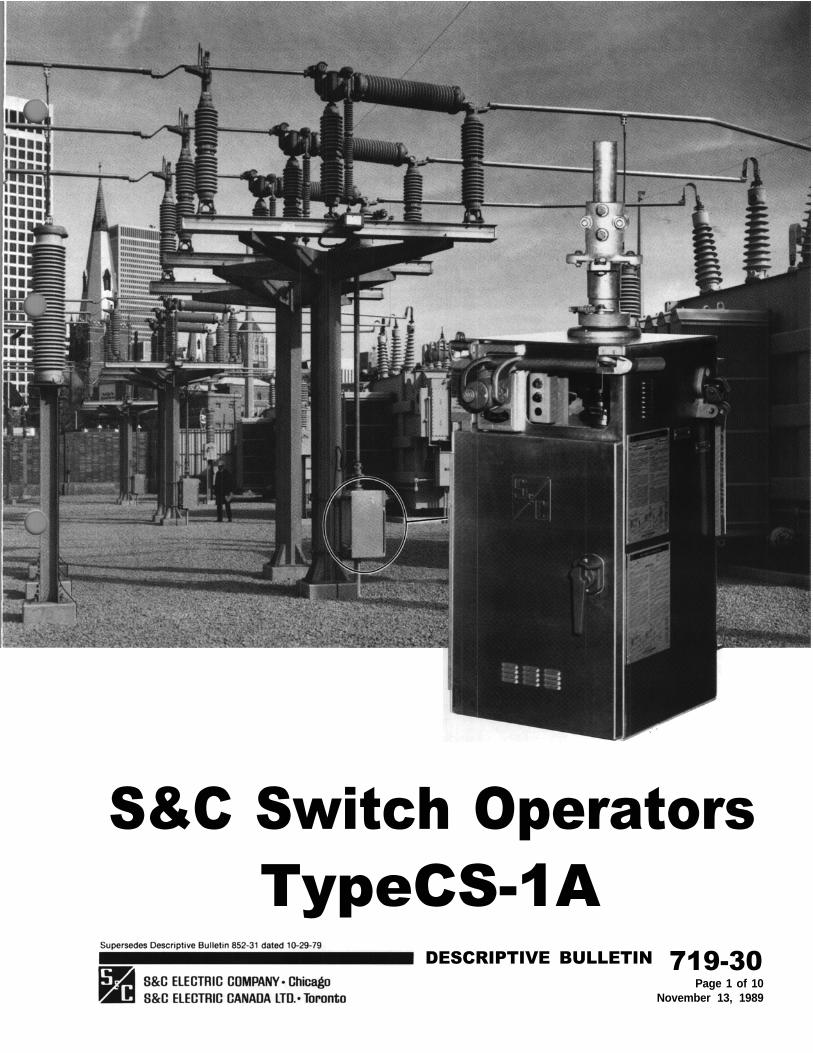
S&C Switch OperatorsTypeCS-1A
DESCRIPTIVE BULLETIN 719-30Page 1 of 10
November 13, 1989

S&C Switch Operators - Type CS-1A
Type CS-1 A Switch Operators are high-speed operators expresslydesigned for power operation of S&C Mark V Circuit-Switchers.Type CS-1A Switch Operators provide the high-speed, of excessive switching transients due to prolonged orhigh-torque power operation required to secure the full unstable prestrike arcing.inherent mechanical and electrical performancecharacteristics of Mark V Circuit-Switchers, including
For Vertical-Break and Integer Style Mark V Circuit-
close interphase simultaneity, long life of fault-closingSwitchers, Type CS-1A Switch Operators also provide
contacts under normal operating duties, and avoidancet w o - t i m e d u t y - c y c l e f a u l t - c l o s i n g r a t i n g s o f30 ,000 amperes rms th ree -phase symmet r i ca l ,
Figure 1. Interior of Type CS-1A Switch Operator.
719-30 DESCRIPTIVE BULLETINPage 2 of 10November 13, 1989

76,500 amperes peak; and opening and closing withouthesitation under ¾-inch ice formation.
opening and closing without hesitation under 1½-inchice formation.
And for Center-Break Style Mark V Circuit-Switchers,Type CS-1A Switch Operators also provide two-tuneduty-cycle fault-closing ratings of 40,000 amperes rmsthree-phase symmetrical, 102,000 amperes peak; and
Shown below in Figure 1 are some of the importantfeatures of Type CS-1A Switch Operators. Thesefeatures are discussed in detail in the “CONSTRUCTIONAND OPERATION” section.
DESCRIPTIVE BULLETIN 719-30Page 3 of 10
November 13, 1989
S&C Switch Operators - Type CS-1A
The EnclosureThe switch operator is housed in a weatherproof,dust proof enclosure of sturdy, 3/32-inch sheet aluminum.All seams are welded and enclosure openings are sealedwith gasketing or O-rings at all possible water-ingresspoints. A fused space heater is provided to maintainair circulation for condensation control. The spaceheater is factory-connected for 240-volt ac operationbut can be readily field-reconnected for 120-volt acoperation. Access to the interior components is by doorrather than by removal of the entire enclosure-anobvious advantage during foul weather. To ensure theutmost security against unauthorized entry, theenclosure includes such features as:
Cam-action latch . . . seals door in compressionagainst gasketTwo concealed hingesLaminated safety-plate glass, gasket-mountedobservation windowPadlockable door handle, pushbutton protectivecover, manual operating handle, and selector handleKey interlock (when specified).
Power TrainThe power train consists essentially of a reversiblemotor coupled to the output shaft at the top of theoperator. Motor direction is controlled by a supervisoryswitch which actuates the open or closing contactoras appropriate to energize the motor and to releasethe electromagnetic brake. Fingertip precision adjust-ment of output-shaft rotation is provided by meansof self-locking spring-biased cams. Antifriction bearingsare used throughout; the gear-train shafts featuretapered roller bearings.
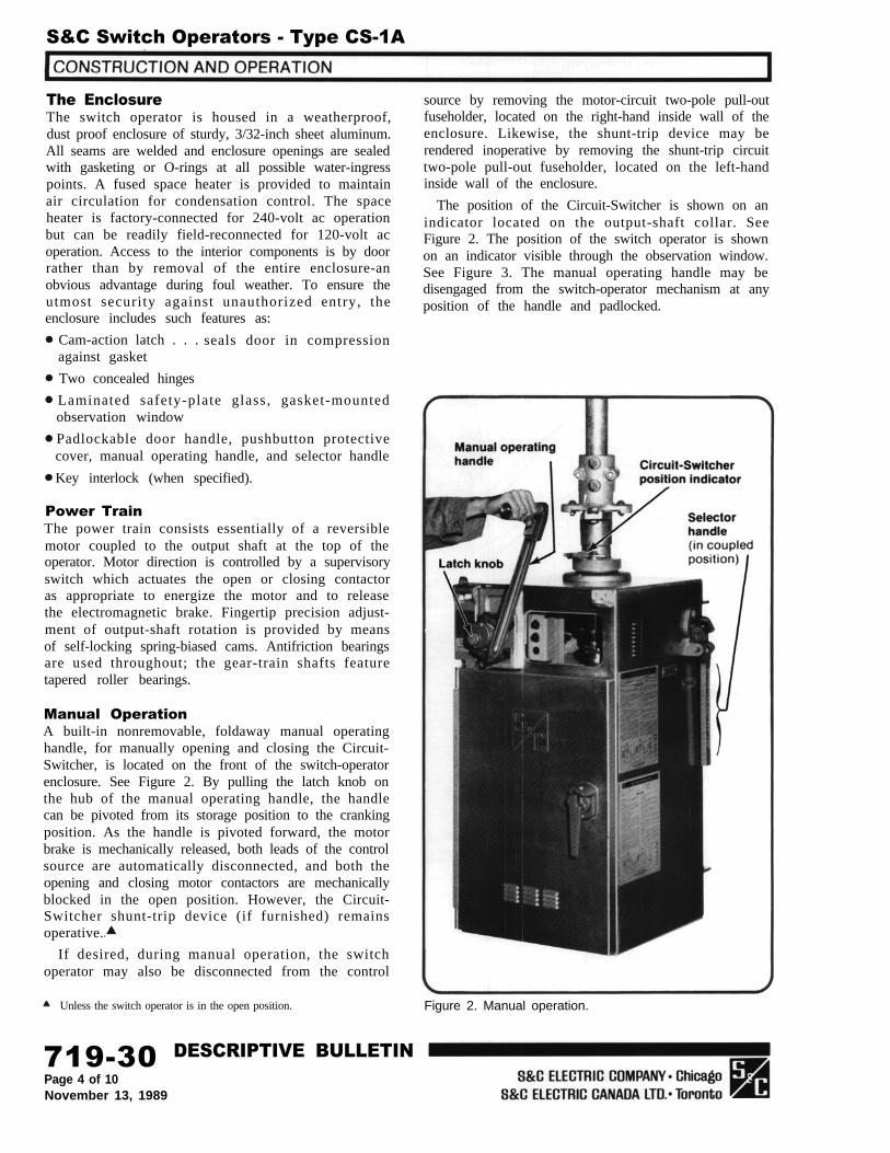
Manual OperationA built-in nonremovable, foldaway manual operatinghandle, for manually opening and closing the Circuit-Switcher, is located on the front of the switch-operatorenclosure. See Figure 2. By pulling the latch knob onthe hub of the manual operating handle, the handlecan be pivoted from its storage position to the crankingposition. As the handle is pivoted forward, the motorbrake is mechanically released, both leads of the controlsource are automatically disconnected, and both theopening and closing motor contactors are mechanicallyblocked in the open position. However, the Circuit-Switcher shunt-trip device (if furnished) remainsoperative.
If desired, during manual operation, the switchoperator may also be disconnected from the control
Unless the switch operator is in the open position.
source by removing the motor-circuit two-pole pull-outfuseholder, located on the right-hand inside wall of theenclosure. Likewise, the shunt-trip device may berendered inoperative by removing the shunt-trip circuittwo-pole pull-out fuseholder, located on the left-handinside wall of the enclosure.
The position of the Circuit-Switcher is shown on anindicator located on the output-shaft collar. SeeFigure 2. The position of the switch operator is shownon an indicator visible through the observation window.See Figure 3. The manual operating handle may bedisengaged from the switch-operator mechanism at anyposition of the handle and padlocked.
Figure 2. Manual operation.
719-30 DESCRIPTIVE BULLETINPage 4 of 10November 13, 1989

Externally Operable InternalDecoupling MechanismAn integral external selector handle, for operation ofthe built-in internal decoupling mechanism, is locatedon the right-hand side of the switch-operator enclosure.See Figure 2. By swinging this handle upright androtating it clockwise 50º–as shown in Figure 3–theswitch-operator mechanism is decoupled from theoutput shaft. When thus decoupled, the switch operatormay be manually or electrically operated withoutoperating the Circuit-Switcher and the shunt-tripdevice (if furnished) is rendered inoperative.*Moreover, when decoupled, the switch-operator outputshaft is prevented from moving by a mechanical lockingdevice within the operator enclosure.
During the intermediate segment of the selectorhandle travel, which includes the position at whichactual disengagement (or engagement) of the internaldecoupling mechanism occurs, the motor-circuit source
* Only the shunt-trip device is rendered inoperative. The switch operatorcan still he opened through the user’s protective-relay circuit. Thus “elective”checkout of the system protective scheme is possible at any time.
leads are momentarily disconnected and both theopening and closing motor contactors are mechanicallyblocked in the open position. Visual inspection, throughthe observation window, will verifywhether the internaldecoupling mechanism is in the coupled or decoupledposition. See Figure 3. The selector handle may bepadlocked in either position.
Recoupling is foolproof. It is impossible to couple an“open” Circuit-Switcher with the switch operator in the“closed” position, or vice-versa. Coupling is possible onlyif the switch-operator output shaft is mechanicallysynchronized with the switch-operator mechanism.This synchronization is readily achieved by manuallyor electrically operating the switch operator to bringit to the same position (open or closed) as the Circuit-Switcher. The switch-operator position indicators, seenthrough the observation window, will show when theapproximate open or closed position has been attained.See Figure 3. Then, to move the switch operator to theexact position for coupling, the manual operatinghandle is turned until the position-indexing drums arenumerically aligned.
Figure 3. Views of switch operator through observation window.
DESCRIPTIVE BULLETIN 719-30Page 5 of 10
November 13, 1989

S&C Switch Operators - Type CS-1A
Travel-Limit AdjustmentA travel-limit switch coupled to the motor governs theextent of output-shaft rotation in the opening andclosing directions. It includes six contacts that areoperated by cam-actuated rollers. Positioning of thecams to properly engage the rollers is accomplishedby means of two travel-limit discs-one for the openingstroke, one for the closing stroke. See Figure 4.
Each travel-limit disc is precisely adjusted by meansof a self-locking spring-biased cam. Opening travel isadjusted by raising and turning the opening-stroketravel-limit disc to the required position on theindicator plate, while holding the handwheel as shown.Similarly, closing travel is adjusted by lowering andturning the closing-stroke travel-limit disc to therequired position on the indicator plate, while holdingthe handwheel.
Figure 4. Adjustment of travel-limit discs.
719-30 DESCRIPTIVE BULLETINPage 6 of 10November 13, 1989

Actuating the opening-stroke travel-limit disc de-energizes the opening contactor, which then de-energizes the brake-release solenoid to halt motion ofthe mechanism. Actuating the closing-stroke travel-limit disc de-energizes the closing contactor, which thenalso de-energizes the brake-release solenoid to haltmotion of the mechanism.
Auxiliary SwitchesAn eight-pole auxiliary switch coupled to the motoris furnished as a standard feature. It provides eightindividually adjustable contacts pre-wired to terminalblocks (six contacts are available if the switch operatoris furnished with optional position-indicating lamps,Catalog Number Suffix “-M”). These contacts arefurnished so that external circuits can be establishedto monitor switching operations.
Like the travel-limit discs, each auxiliary switchcontact has a self-locking spring-biased cam whichpermits precise adjustment of cam-roller engagementat the desired point in the operating cycle. Cam positionis adjusted by raising (or lowering) the cam towardits adjacent spring and rotating it to the desiredposition. See Figure 5. An extra four-pole auxiliaryswitch coupled to the motor and utilizing the sameconstruction is available as an option (Catalog Numbersuffix “-Q”).
An extra auxiliary switch coupled to the Circuit-Switcher is also available as an option, and can beprovided so that external contacts can be establishedto monitor Circuit-Switcher operations. This auxiliaryswitch also utilizes self-locking spring-biased cams. Itcan be furnished in an eight-pole version (CatalogNumber Suffi “-W”) or in a twelve-poleversion (CatalogNumber Suffix “-Z”).
Figure 5. Adjustment of cams on auxiliary switch.
DESCRIPTIVE BULLETIN 719-30Page 7 of 10
November 13, 1989
S&C Switch Operators - Type CS-1A
Provision for S&C Shunt-Trip DeviceS&C Mark V Circuit-Switchers equipped with theoptional S&C Shunt-Trip Device provide 8-cyclemaximum interrupting time. This high-speed circuitinterruption facilitates the application of circuit-switchers at the primary side of transformers forprotection of the transformers against internal faults,for multiple-contingency backup protection foroverloads and secondary faults, and for protection ofthe source-side circuits from all kinds of transformerfaults.
When the shunt-trip device is energized, a high-speedsolenoid encased in a weatherproof housing on eachpole-unit base rotates the slender low-inertia insulatedshaft 15 degrees. This releases the stored energy withinthe brain for high-speed opening of the interrupter.
Type CS-1A Switch Operators, furnished with Mark VCircuit-Switchers equipped with the shunt-trip device,can be provided with an optional shunt-trip contactorand time-delay relay (Catalog Number Suffix “-HP”).This optional feature minimizes control-current inrushby energizing the shunt-trip device and switch-operatormotor in sequence, thus generally permitting the useof smaller-sized control wire between the user’sprotective or control relay and the switch operator.
Sequence ControlCorrect operation of Mark V Circuit-Switchers dependson charging and latching the stored-energy sourcewithin each brain as the disconnect blades move tothe fully open position. The interrupter target locatedon the side of each brain housing appears yellow whenthe interrupter is open. The target appears gray(normal) when the interrupter is closed.
Interrupters should never be open while the bladesare in the closed position. To close the interrupters,Circuit-Switcher must be completely opened and thenreclosed. For this reason, the switch operator incor-porates a control circuit that causes the switchoperator to return automatically to the open positionwhenever the control-source voltage is restored whilethe switch operator is at any position between fullyopen and fully closed. Such action takes placeregardless of the direction in which it was operatingprior to loss of voltage. This control circuit is a built-in feature to prevent Circuit-Switcher from being closedfrom a partially open position after the interruptershave tripped open.
719-30 DESCRIPTIVE BULLETINPage 8 of 10November 13, 1989

SWITCH OPERATORS - TYPE CS-1A
Based on minimum battery and external control wire size requirementsspecified in S&C Data Bulletin 719-60. operating time will be less if largr-than-minimum battery size and/or external control wire size is utilized.
The Type CS-1A Switch Operator is also suitable for use with equivalentmodels of Mark II, Mark III, and Mark IV Circuit-Switchers. Consult thenearest S&C Sales Office.
Catalog Number 38858R1-B, for applications where the Circuit-Switcheris used in conjunction with an S&C Automatic Control Device, unless theswitch operator is ordered with the optional Shunt-Trip Contactor andTime-Delay Relay accessory, Catalog Number Suffix “-HP.” In this instance,the catalog number is 3RS46R5-BHP.
CDR-3183 for Catalog Number 38846R5-BHP. CDR-3195 for CatalogNumber 3885SR1-B.
ACCESSORIES
Available as an optional accessory only with S&C Switch OperatorCatalog Number 38846R5-B; included as standard equipment with CatalogNumber 38846R5-AHP. Permits use of minimum-size control wire.
Not available in applications utilizing an S&C Circuit-Switcher Relayand Control Pack.
The 8-PST Extra Auxiliary Switch (Suffix “-W” cannot be furnishedNot available with S&C Switch Operator Catalog Number 38858R1-B. if the 12-PST version (Suffix “-Z”) is specified, and vice versa
Page 9 of 10November 13, 1989
DESCRIPTIVE BULLETIN 719-30

S&C Switch Operators - Type CS-1A
719-30 DESCRIPTIVE BULLETINPage 10 of 10November 13, 1989