Embed Size (px)
Citation preview

APOLLO Gate Operators, Inc.
Model 1550ETL Single Swing Gate Operator
INSTALLATION MANUAL
04/07
Model 1650ETL Dual Swing Gate Operator
2
CONTENTS
IMPORTANT SAFETY INSTRUCTIONS ..................... 3
Applications .............................................................. 4
Pre-Installation Checklist ........................................ 5
Parts Identification ................................................... 6
Operator Installation ................................................ 7-9 Pivot Arm Installation Actuator Installation Control Box Installation Connecting the Actuator Gate Bracket Installation Limit Switch Adjustment Control Board Connections Control Board Adjustments - Learn Mode
1550ETL/1650ETL Actuator Option ………………….. 10
Push to Open Installation .......................................... 11
Programming Instructions ……………………………. 12
Control Board Description ……………………………. 13-17
Siren Connection ……………………………………… 18
Radio Receiver Options ............................................. 19
Troubleshooting guide .............................................. 20-22
Warranty .................................................................... 23

3
WARNING - To reduce the risk of injury or death:
READ AND FOLLOW ALL INSTRUCTIONS.
Installation should be performed by a professional installer.
Required welding should be performed by a qualified welder.
Should electricity be required, use a certified electrician only.
Any device that requires 120 Volts AC should be U.L. approved.
Review with the owner all safety concerns including:
Do not operate the gate unless area around gate is in full view.Never let children operate or play with gate controls. Keep the remote controlaway from children.Always keep people and objects away from the gate. NO ONE SHOULD CROSSTHE PATH OF THE MOVING GATE.Periodically test the obstruction sensitivity to assure safe and properoperation. Do not test sensitivity by standing between the gate and the hinge orstop post.The “CAUTION AUTOMATIC GATE” signs should be clearly visible from bothsides of the gate.Always insure that the gate has closed securely before leaving area.Arrange with local fire and law enforcement for emergency access.
Use the emergency release only when the gate is not moving.
A secondary entrapment device such as loop detectors, edge switches, and beamdetectors are highly recommended and required to meet the UL325 standard.
Install control devices such as keypads far enough away (5 feet or further) from anymoving parts of the operator and gate to prevent possible injury.
Do not install control box where the gate can come in contact with person using thepush button on side of control box.
Always disconnect the battery or power source when making adjustments or repairs toany part of the gate or operator.
All rollers should be covered to prevent injury.
KEEP GATES PROPERLY MAINTAINED. Read the owner’s manual. Have a qualifiedservice person make repairs to gate hardware.
The entrance is for vehicles only. Pedestrians must use separate entrance.
Test the gate operator monthly. The gate MUST reverse on contact with a rigid object orstop when an object activates the non contact sensors. After adjusting the force or limit oftravel, retest the gate operator. Failure to adjust and retest the gate operator properly canincrease the risk of injury or death.
SAVE THESE INSTRUCTIONS.
IMPORTANT SAFETY INSTRUCTIONS

4
APPLICATIONS
The Apollo Model 1550ETL/1650ETL Swing Gate Operator is approved for Vehicu-lar Class I & II usage under UL 325 Guidelines, and is designed to handle swinggates up to 16 feet in length and 600 pounds each. A professional fence or gatedealer is recommended to assure proper installation. Apollo Gate Operators areavailable only through qualified dealers with an outstanding reputation in the fenceand gate industry. These dealers will be able to recommend the proper equipmentfor particular applications. Apollo Gate Operators are 12 Volt DC (Direct Current)powered. A 12 Volt sealed battery (33 ampere hour minimum) with connectingposts located on the top is recommended. There are several advantages with 12Volt DC systems:
Low voltage virtually eliminates risk of electrical shock.
Battery powered operators provide up to 200 operations in the event ofpower outages.
The battery may be recharged with a trickle charger or by solar energy(Electrical battery chargers should have a class 2 transformer rating).
If a trickle charger is used and a standard electrical outlet is not readily available, alicensed electrician will be required for proper electrical hook up.
The following table should be used as a guide for capacity of operation of operatorsonly, additional options may reduce the the daily usage. Please note that the chargecapability of solar panels will vary with different geographical locations.
Daily Cycles 1-10 1-20 1-40 1-60 1-80 80+
5 watt solar panel *
10 watt solar panel *
20 watt solar panel (requires 5310 regulator) *
30 watt solar panel (requires 5310 regulator) *
40 watt solar panel (requires 5310 regulator) *
1.5 amp battery charger *
10 amp battery charger *
Note: Double the amount of solar panels for Dual Gate Operators.
5
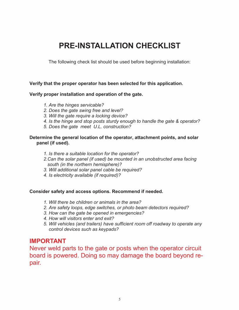
PRE-INSTALLATION CHECKLIST
The following check list should be used before beginning installation:
Verify that the proper operator has been selected for this application.
Verify proper installation and operation of the gate.
1. Are the hinges servicable?2. Does the gate swing free and level?3. Will the gate require a locking device?4. Is the hinge and stop posts sturdy enough to handle the gate & operator?5. Does the gate meet U.L. construction?
Determine the general location of the operator, attachment points, and solarpanel (if used).
1. Is there a suitable location for the operator?2.Can the solar panel (if used) be mounted in an unobstructed area facing south (in the northern hemisphere)?3. Will additional solar panel cable be required?4. Is electricity available (if required)?
Consider safety and access options. Recommend if needed.
1. Will there be children or animals in the area?2. Are safety loops, edge switches, or photo beam detectors required?3. How can the gate be opened in emergencies?4. How will visitors enter and exit?5. Will vehicles (and trailers) have sufficient room off roadway to operate any control devices such as keypads?
IMPORTANTNever weld parts to the gate or posts when the operator circuitboard is powered. Doing so may damage the board beyond re-pair.
6
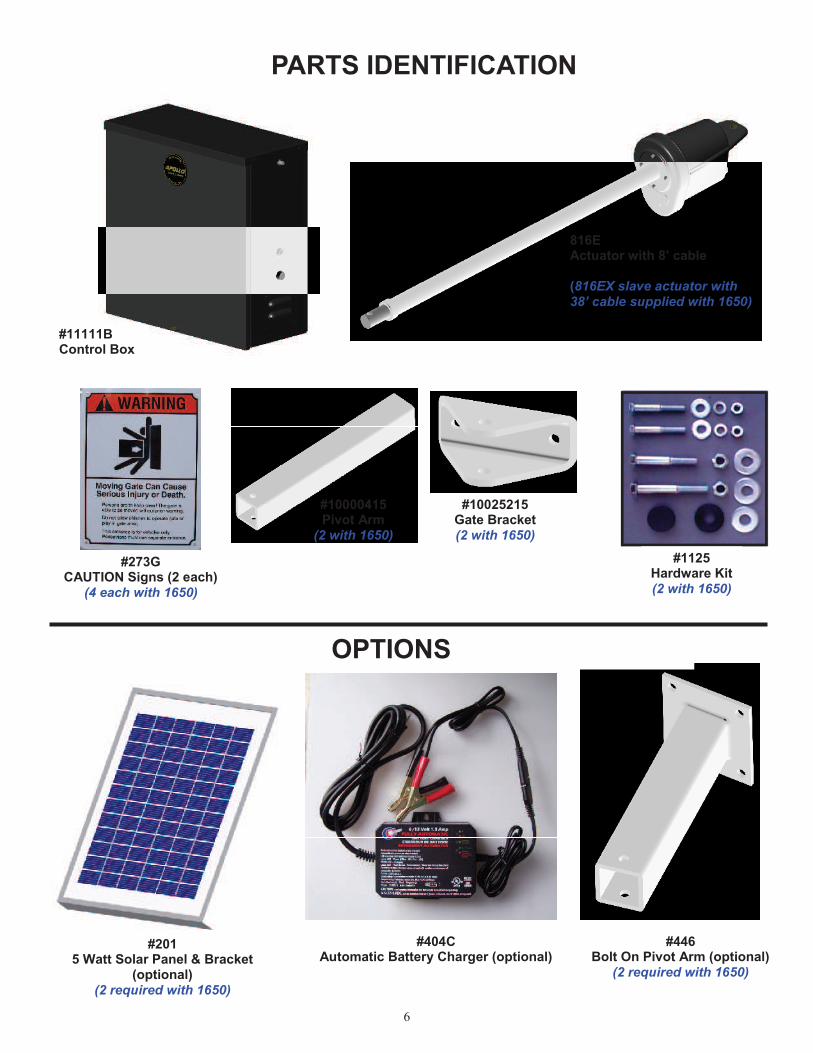
PARTS IDENTIFICATION
#10025215Gate Bracket(2 with 1650)
#1125Hardware Kit(2 with 1650)
#404CAutomatic Battery Charger (optional)
#2015 Watt Solar Panel & Bracket
(optional)(2 required with 1650)
816EActuator with 8’ cable
(816EX slave actuator with38’ cable supplied with 1650)
#11111BControl Box
#10000415Pivot Arm
(2 with 1650)
#446Bolt On Pivot Arm (optional)
(2 required with 1650)
#273GCAUTION Signs (2 each)
(4 each with 1650)
OPTIONS
7
OPERATOR INSTALLATION
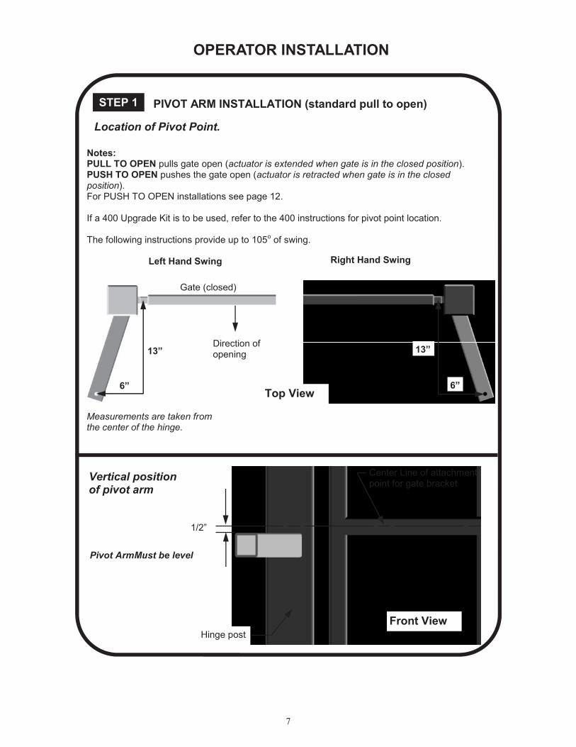
Location of Pivot Point.
1/2”
Center Line of attachmentpoint for gate bracket
Hinge post
Vertical positionof pivot arm
Measurements are taken fromthe center of the hinge.
STEP 1 PIVOT ARM INSTALLATION (standard pull to open)
Front View
Pivot ArmMust be level
Notes:PULL TO OPEN pulls gate open (actuator is extended when gate is in the closed position).PUSH TO OPEN pushes the gate open (actuator is retracted when gate is in the closedposition).For PUSH TO OPEN installations see page 12.
If a 400 Upgrade Kit is to be used, refer to the 400 instructions for pivot point location.
The following instructions provide up to 105o of swing.
Gate (closed)
13”
6”
Direction ofopening
13”
6”
Left Hand Swing Right Hand Swing
Top View

8
STEP 3 Control Box Installation
Mount the control box within 4 feet of the pivot arm.Do not mount the control box where the personusing the push button on side of the box cancome in contact with the gate. Use mountinghardware capable of supporting the weight of thecontrol box with the battery installed.
STEP 4 Connecting the Actuator (s)
Set battery inside of control box with terminalstoward the front (Do not use any battery with sideterminals).
Connect actuator cable to the “MASTER” connector on thecontrol board.
If a 1650 Dual Operator is being installed and conduit isbeing used under the drive (recommended), cut the slave(opposite side where control box is mounted) actuator cableabout 12” from the white connector. Run the remainingcable across the drive through conduit and up through thecontrol box. Cutoff any excess cable and splice the shortpiece back to the cable.* Connect to the “SLAVE” connectoron the control board.
Connect the RED power wire (s) to the battery positive ( + )and the BLACK power wire (s) to the battery negative ( - )
1/2” x 3 1/2” Hex Bolt
1/2” Washer
1/2” Lock Nut
Do not over tighten nut
Actuator InstallationSTEP 2
* Instead of cutting the slave cable, remove the pins on the plug with a jeweler’s common bladescrewdriver or appropriate tool (the staples on the actuator shipping carton work great) ,run thecable through the conduit and reinsert the pins into the plug.
MASTERSLAVE
9
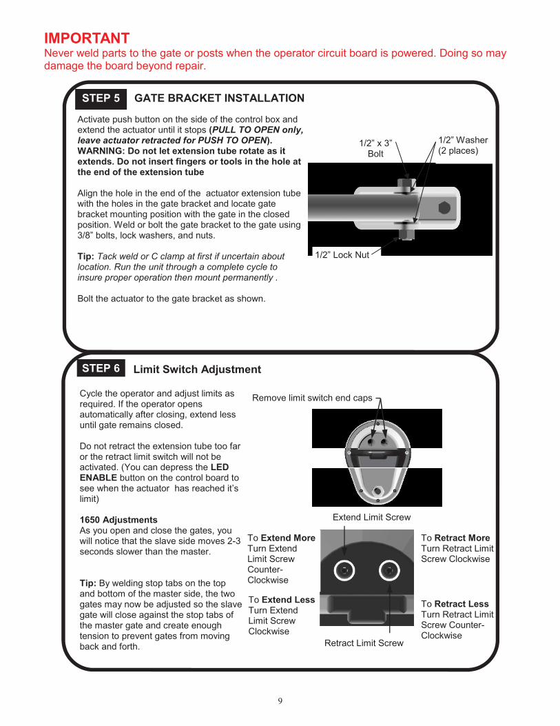
STEP 6 Limit Switch Adjustment
To Retract MoreTurn Retract LimitScrew Clockwise
To Retract LessTurn Retract LimitScrew Counter-Clockwise
To Extend MoreTurn ExtendLimit ScrewCounter-Clockwise
To Extend LessTurn ExtendLimit ScrewClockwise
Remove limit switch end capsCycle the operator and adjust limits asrequired. If the operator opensautomatically after closing, extend lessuntil gate remains closed.
Do not retract the extension tube too faror the retract limit switch will not beactivated. (You can depress the LEDENABLE button on the control board tosee when the actuator has reached it’slimit)
1650 AdjustmentsAs you open and close the gates, youwill notice that the slave side moves 2-3seconds slower than the master.
Tip: By welding stop tabs on the topand bottom of the master side, the twogates may now be adjusted so the slavegate will close against the stop tabs ofthe master gate and create enoughtension to prevent gates from movingback and forth.
STEP 5 GATE BRACKET INSTALLATION
Activate push button on the side of the control box andextend the actuator until it stops (PULL TO OPEN only,leave actuator retracted for PUSH TO OPEN).WARNING: Do not let extension tube rotate as itextends. Do not insert fingers or tools in the hole atthe end of the extension tube
Align the hole in the end of the actuator extension tubewith the holes in the gate bracket and locate gatebracket mounting position with the gate in the closedposition. Weld or bolt the gate bracket to the gate using3/8” bolts, lock washers, and nuts.
Tip: Tack weld or C clamp at first if uncertain aboutlocation. Run the unit through a complete cycle toinsure proper operation then mount permanently .
Bolt the actuator to the gate bracket as shown.
1/2” x 3”Bolt
1/2” Lock Nut
1/2” Washer(2 places)
Extend Limit Screw
Retract Limit Screw
IMPORTANTNever weld parts to the gate or posts when the operator circuit board is powered. Doing so maydamage the board beyond repair.
10
1550ETL / 1650ETL Actuator Option
The Apollo 1550ETL and 1650ETL systems – which use the 835/836 boards – comestandard with the 816E / 816EX actuators. These actuators have a gray cable restraintand are considered our “smart” or “intelligent” actuator. These actuators utilize all ofthe features of the 835/836 board.
Please note that if a 416 (non-intelligent actuator) is to be used on a1550ETL / 1650ETL system:
1. Switch #10 (SMART ACT.) must be in the OFF position.
2. The “slow start” / “slow stop” feature of the 835/836 board will not work withthe 416 actuators.
The rest of the set-up and operation of the system is the same as with the “smart”actuators. For example, limit switches on the actuator must be set before proceedingwith the current sensing procedure.
Cable Length of 816E / 816EX Actuators
It is not recommended to lengthen or shorten the cables of these actuators – as theyhave a sensor in the actuator. Should special length cables be required, they areavailable by special order in any length up to 50 feet.
If it is necessary to cut the cable, special attention should be given to ensure thatproper electrical splices are performed.
Should the cable of the 816E / 816EX actuator need to be pulled thru conduit, it isrecommended that the plug be removed, cable pulled, then the plug re-installed.(Specific instructions for this are available from your distributor or Apollo TechnicalAssistance.)
11
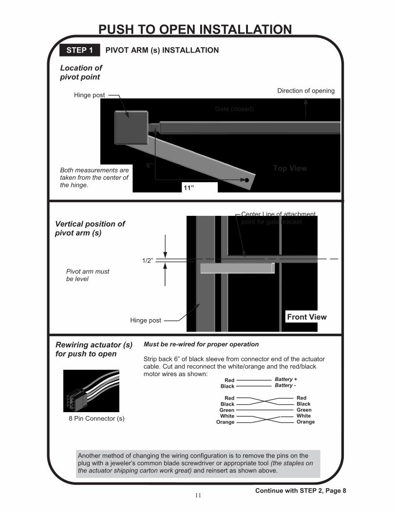
PUSH TO OPEN INSTALLATION
Both measurements aretaken from the center ofthe hinge. 11”
6”
Direction of opening
Gate (closed)
Hinge post
Top View
Vertical position ofpivot arm (s)
Pivot arm mustbe level
1/2”
Hinge post
Center Line of attachmentpoint for gate bracket
Front View
PIVOT ARM (s) INSTALLATIONSTEP 1
Location ofpivot point
Rewiring actuator (s)for push to open
Must be re-wired for proper operation
Strip back 6” of black sleeve from connector end of the actuatorcable. Cut and reconnect the white/orange and the red/blackmotor wires as shown:
8 Pin Connector (s)
RedBlack
RedBlackGreenWhite
Orange
RedBlackGreenWhiteOrange
Battery +Battery -
Continue with STEP 2, Page 8
Another method of changing the wiring configuration is to remove the pins on theplug with a jeweler’s common blade screwdriver or appropriate tool (the staples onthe actuator shipping carton work great) and reinsert as shown above.
12
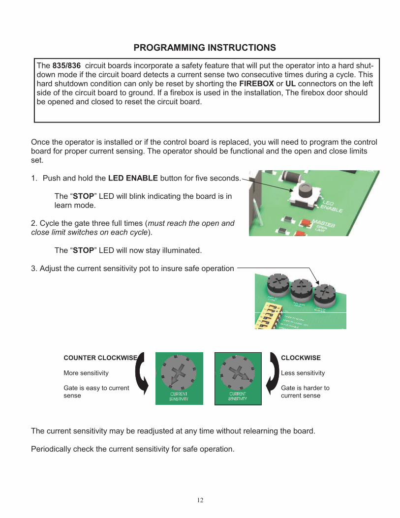
PROGRAMMING INSTRUCTIONS
Once the operator is installed or if the control board is replaced, you will need to program the controlboard for proper current sensing. The operator should be functional and the open and close limitsset.
1. Push and hold the LED ENABLE button for five seconds.
The “STOP” LED will blink indicating the board is inlearn mode.
2. Cycle the gate three full times (must reach the open andclose limit switches on each cycle).
The “STOP” LED will now stay illuminated.
3. Adjust the current sensitivity pot to insure safe operation
The current sensitivity may be readjusted at any time without relearning the board.
Periodically check the current sensitivity for safe operation.
The 835/836 circuit boards incorporate a safety feature that will put the operator into a hard shut-down mode if the circuit board detects a current sense two consecutive times during a cycle. Thishard shutdown condition can only be reset by shorting the FIREBOX or UL connectors on the leftside of the circuit board to ground. If a firebox is used in the installation, The firebox door shouldbe opened and closed to reset the circuit board.
CLOCKWISE
Less sensitivity
Gate is harder tocurrent sense
COUNTER CLOCKWISE
More sensitivity
Gate is easy to currentsense
13
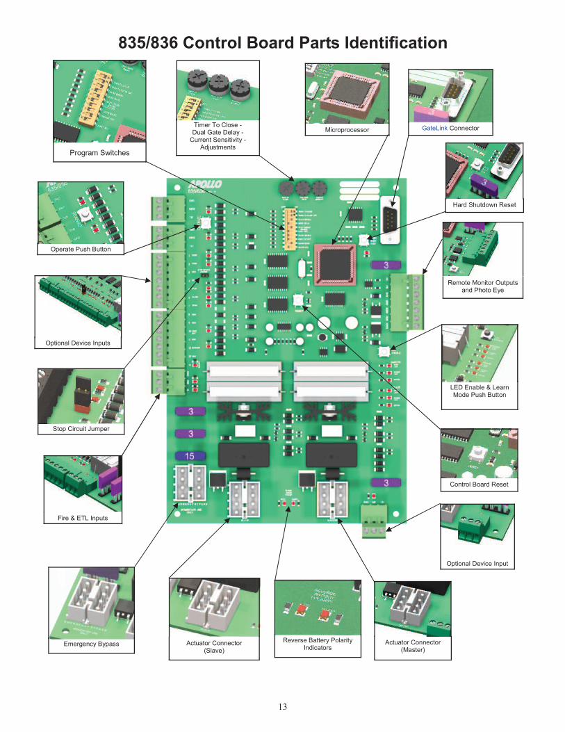
LED Enable & LearnMode Push Button
Optional Device Inputs
Stop Circuit Jumper
Fire & ETL Inputs
Emergency BypassReverse Battery Polarity
Indicators
Optional Device Input
Remote Monitor Outputsand Photo Eye
GateLink ConnectorMicroprocessorTimer To Close -Dual Gate Delay -
Current Sensitivity -Adjustments
Program Switches
835/836 Control Board Parts Identification
Actuator Connector(Master)
Actuator Connector(Slave)
Control Board Reset
Hard Shutdown Reset
Operate Push Button
14
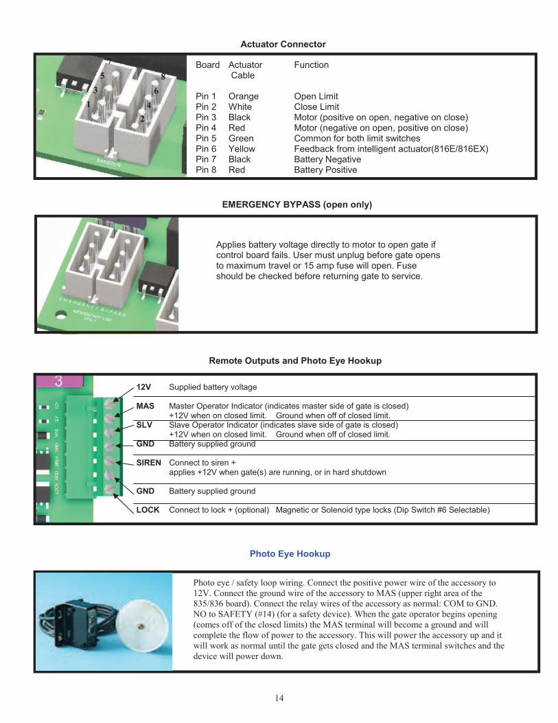
Board Actuator Function Cable
Pin 1 Orange Open LimitPin 2 White Close LimitPin 3 Black Motor (positive on open, negative on close)Pin 4 Red Motor (negative on open, positive on close)Pin 5 Green Common for both limit switchesPin 6 Yellow Feedback from intelligent actuator(816E/816EX)Pin 7 Black Battery NegativePin 8 Red Battery Positive
1
3
5
7
2
4
6
8
Actuator Connector
Applies battery voltage directly to motor to open gate ifcontrol board fails. User must unplug before gate opensto maximum travel or 15 amp fuse will open. Fuseshould be checked before returning gate to service.
EMERGENCY BYPASS (open only)
Photo eye / safety loop wiring. Connect the positive power wire of the accessory to
12V. Connect the ground wire of the accessory to MAS (upper right area of the
835/836 board). Connect the relay wires of the accessory as normal: COM to GND.
NO to SAFETY (#14) (for a safety device). When the gate operator begins opening
(comes off of the closed limits) the MAS terminal will become a ground and will
complete the flow of power to the accessory. This will power the accessory up and it
will work as normal until the gate gets closed and the MAS terminal switches and the
device will power down.
Photo Eye Hookup
12V Supplied battery voltage
MAS Master Operator Indicator (indicates master side of gate is closed)+12V when on closed limit. Ground when off of closed limit.
SLV Slave Operator Indicator (indicates slave side of gate is closed)+12V when on closed limit. Ground when off of closed limit.
GND Battery supplied ground
SIREN Connect to siren +applies +12V when gate(s) are running, or in hard shutdown
GND Battery supplied ground
LOCK Connect to lock + (optional) Magnetic or Solenoid type locks (Dip Switch #6 Selectable)
Remote Outputs and Photo Eye Hookup

15
Adjustments
Push Buttons
TIMER TO CLOSE Adjusts time before gate automatically closesAdjustable 5 to 70 seconds.
DUAL GATE DELAY Adjusts delay between master and slave op-eration 0-4 seconds (836 only for use withmagnetic, solenoid, and other locking devices)
CURRENT SENSITIVITY Increases or decreases the Auto Reversesensitivity.
LED ENABLE When depressed, activates LEDs for 15minutes to assist in installation and troubleshooting.
Hold the push button down for five seconds to putthe board in program mode.
RESET Resets the microprocessor. Returns processor tolast known state.
OPERATE When depressed, activates the gate. Used for initialinstallation and testing.
Hard Shutdown Reset Resets the operator when the gate currentsenses twice before fully opening or closing.
Jumpers
STOP CIRCUIT JUMPER When the STOP CIRCUITprogram switch #5 must be ON JUMPER is connected, the gate
will operate normally.
STOP CIRCUIT JUMPER When a 3-button station is con-program switch #5 must be OFFnected to the board, the STOP
CIRCUIT JUMPER must be re-moved.

16
Program Switches
OFF ON1 TIMER TO CLOSE Gate does not automatically close. Gate automatically closes.
2 TIMER TO CLOSE OPT. Gate automatically closes from Gate automatically closes only when completelyany position after opening. open (open limit engaged).
3 SLAVE DISABLE Enables slave side (dual gate use). Disables slave side. (single gate use)
4 SIREN DELAY Siren (optional) active when gate is Siren (optional) starts 5 seconds before gate moves.moving.
5 ‘STOP’ CIRCUIT ENABLE Must hold down open or close Normal operationbuttons to move gate. Gate stops Momentary open or close input runs gate to limit.when button released.
6 LOCK TYPE For 12V mechanical (solenoid) locks. For 12V magnetic locks.(+12V for 4 seconds on open cycle) (+12V when on close limit)
7 COAST ENABLE Gate will stop immediately when at Gate will coast (minimally) when it reaches limits.Open or Close limit Recommended for 7500 slide operator only.
8 FREE EXIT OPT. A free exit input will open gate from A free exit input will open gate from anyclosed position or after a close cycle position after an open or close cycle.only.
9 DUAL GATE SYNC Both gates operate at normal This feature will control the master gate to openSpeed (slave slower than or close at the same speed as the slave gate.Master).
10 SMART ACT. Off for 416E & 416EX actuators, Used for 816E & 816EX actuators onlyslide gates, 3500 or when slow down (soft start & stop).feature is not desired.
17
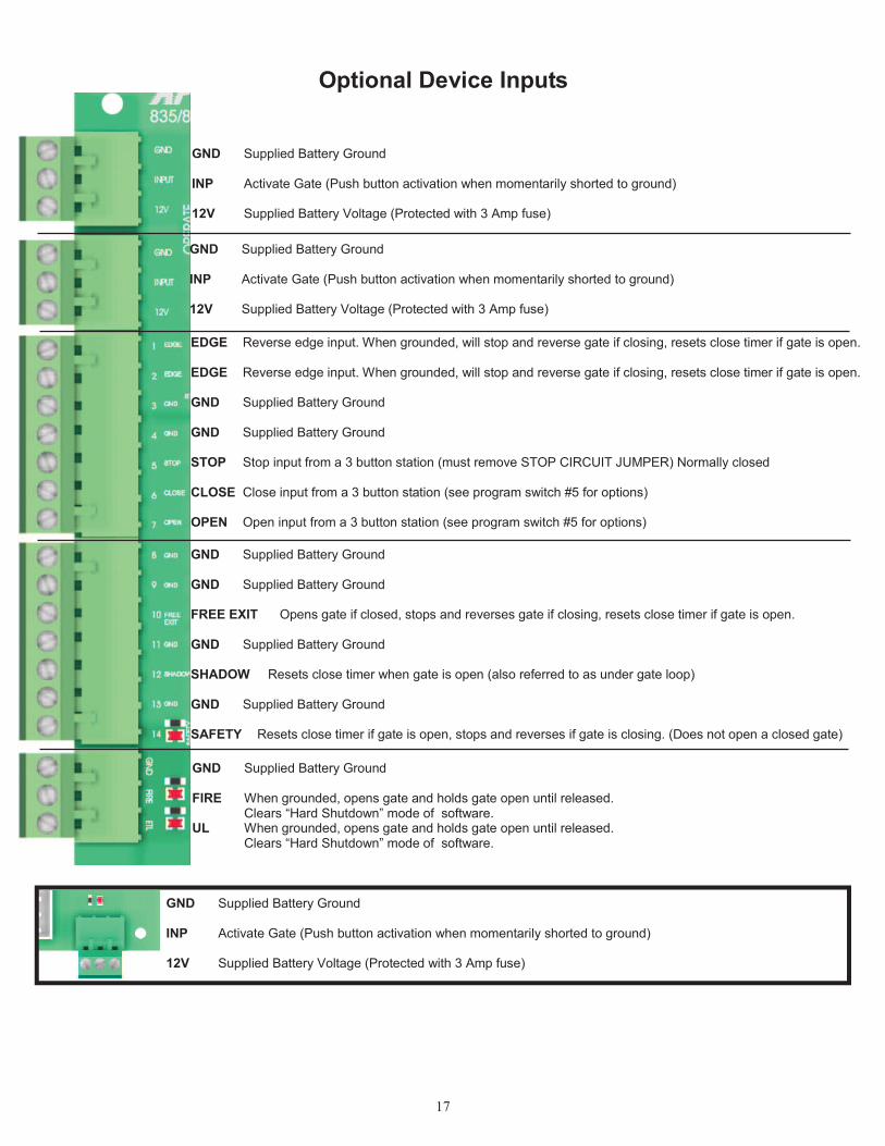
GND Supplied Battery Ground
INP Activate Gate (Push button activation when momentarily shorted to ground)
12V Supplied Battery Voltage (Protected with 3 Amp fuse)
GND Supplied Battery Ground
INP Activate Gate (Push button activation when momentarily shorted to ground)
12V Supplied Battery Voltage (Protected with 3 Amp fuse)
EDGE Reverse edge input. When grounded, will stop and reverse gate if closing, resets close timer if gate is open.
EDGE Reverse edge input. When grounded, will stop and reverse gate if closing, resets close timer if gate is open.
GND Supplied Battery Ground
GND Supplied Battery Ground
STOP Stop input from a 3 button station (must remove STOP CIRCUIT JUMPER) Normally closed
CLOSE Close input from a 3 button station (see program switch #5 for options)
OPEN Open input from a 3 button station (see program switch #5 for options)
GND Supplied Battery Ground
GND Supplied Battery Ground
FREE EXIT Opens gate if closed, stops and reverses gate if closing, resets close timer if gate is open.
GND Supplied Battery Ground
SHADOW Resets close timer when gate is open (also referred to as under gate loop)
GND Supplied Battery Ground
SAFETY Resets close timer if gate is open, stops and reverses if gate is closing. (Does not open a closed gate)
GND Supplied Battery Ground
FIRE When grounded, opens gate and holds gate open until released.Clears “Hard Shutdown” mode of software.
UL When grounded, opens gate and holds gate open until released.Clears “Hard Shutdown” mode of software.
Optional Device Inputs
GND Supplied Battery Ground
INP Activate Gate (Push button activation when momentarily shorted to ground)
12V Supplied Battery Voltage (Protected with 3 Amp fuse)
18
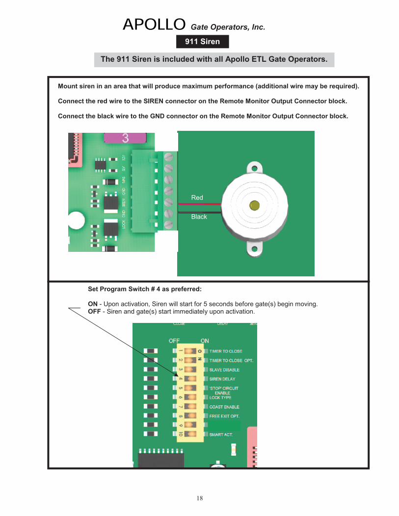
APOLLO Gate Operators, Inc.
911 Siren
Mount siren in an area that will produce maximum performance (additional wire may be required).
Connect the red wire to the SIREN connector on the Remote Monitor Output Connector block.
Connect the black wire to the GND connector on the Remote Monitor Output Connector block.
Red
Black
Set Program Switch # 4 as preferred:
ON - Upon activation, Siren will start for 5 seconds before gate(s) begin moving.OFF - Siren and gate(s) start immediately upon activation.
The 911 Siren is included with all Apollo ETL Gate Operators.
19
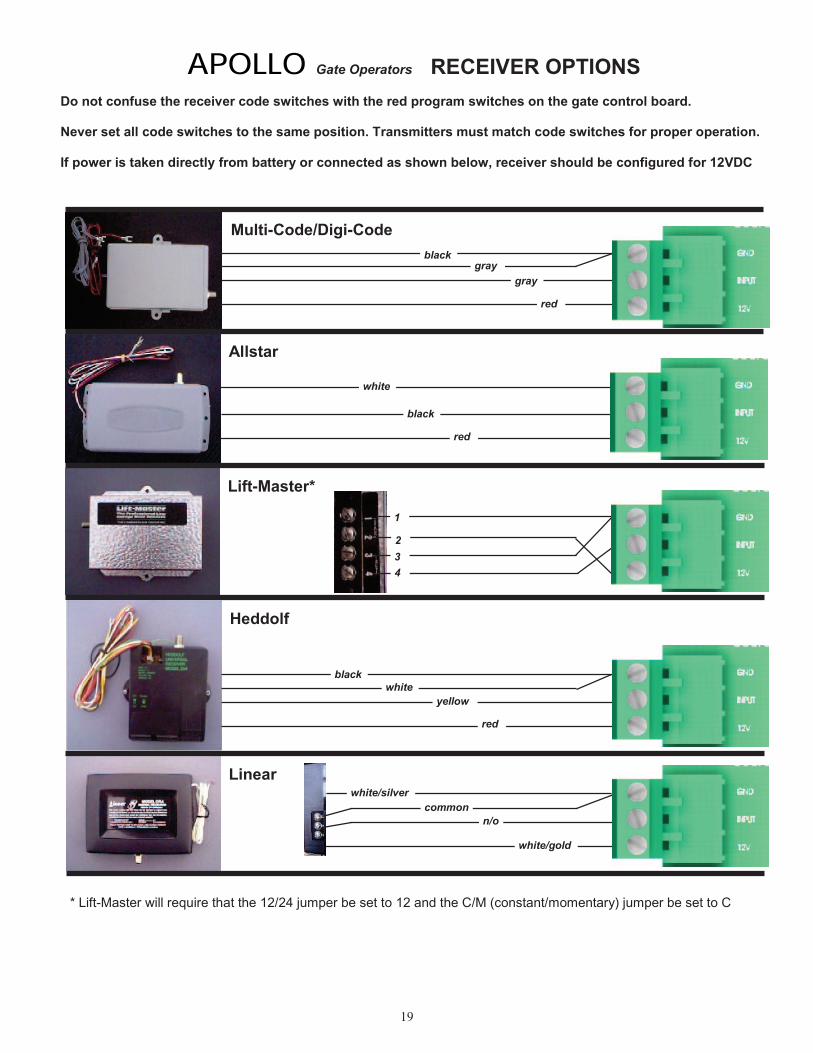
APOLLO Gate Operators RECEIVER OPTIONS
Do not confuse the receiver code switches with the red program switches on the gate control board.
Never set all code switches to the same position. Transmitters must match code switches for proper operation.
If power is taken directly from battery or connected as shown below, receiver should be configured for 12VDC
Multi-Code/Digi-Code
Allstar
Lift-Master*
blackgray
gray
red
white
black
red
4
3
2
1
Heddolf
Linear
black
yellow
red
white/silver
common
n/o
white/gold
white
* Lift-Master will require that the 12/24 jumper be set to 12 and the C/M (constant/momentary) jumper be set to C
20
TROUBLESHOOTING OPERATOR & ACCESSORIES
SYMPTOM
Some troubleshooting will require a hand held multimeter. An inexpensive digital multimeter may bepurchased at Radio Shack or a local electric supply company. Refer to the owners manual forinstructions.
Gate opens OK but after closing, opens back up.
1. Excessive closing pressure on gate. Re-adjust the close limit switch on the actuator.
2. Automatic reverse sensitivity is set too sensitive. Re-adjust - CAUTION: Automatic reverse sensitivityshould be set sensitive enough to avoid injury.
3. Gate is mechanically binding. Disconnect actuator from gate and eliminate binding.
4. Battery voltage is too low. Battery voltage should be 12 to 14 volts under load. Check solar panel output orbattery charger output or re-evaluate usage.
5. Replace circuit board.
SYMPTOM Gate moves only a few feet, then stops or reverses.
1. Battery voltage is too low. Battery voltage should be 12 to 14 volts under load. Check solar panel output orbattery charger output or reevaluate usage.
2. Gate is mechanically binding. Disconnect actuator from gate and eliminate binding.
3. Actuator extension tube is bent. Inspect for damage and replace extension tube if required.
4. Current sensitivity is adjusted too sensitive. Re-adjust current sensitivity.
5. Program switch #10 is on using a non-intelligent (416E) actuator. Turn switch #10 off.
5. Replace circuit board.
SYMPTOM Gate surges too much. Does not run smooth.
1. Pivot arm is not ridged. Re-weld and/or brace pivot arm.
2. Bolts are loose. Snug all bolts. Pivot arm bolt should be snug but not tight.
3. Gate is too limber. Reinforce gate.
21
SYMPTOM Gate will open using push button on side of box, but not with transmitter.
1. Code switches do not match. Check that the code switches in the transmitter and the receiver match.
2. Low or dead battery in transmitter. Replace battery.
3. Fuse blown on circuit board. Check fuses on gate control board.
4. Low battery in operator. Battery voltage should be 12 to 14 volts under load.
5. Replace receiver.
Note: Code switches for receiver are inside of receiver. Do not confuse with program switches on control board.
SYMPTOM Transmitter works, but not very far.
Note: Transmission distances will vary according to terrain, obstructions, and electrical interference.The normal range from inside a vehicle is 50-100 feet while 100-150 feet may be obtained from outsidethe vehicle.
1. Low battery in transmitter. Replace battery.
2. Transmitter malfunctioning. Try a different transmitter.
3. Antenna not making good connection. Be sure center conductor of antenna is penetrating the femaleconnector on the side of the gate box.
4. Reception is being blocked. Raise the height of the antenna using a #244 antenna extension kit.
5. Replace receiver.
SYMPTOM Gate randomly opens, closes, or stops for no reason.
1. Transmitter is stuck on. Check all transmitters, keypads, pushbuttons, etc. for a stuck button.
2. Transmitter and receiver code switches are all down, up, or in the middle. Change at least one switchposition in the transmitter and receiver.
3. Push button on side of control box is defective. Disconnect and test.
22
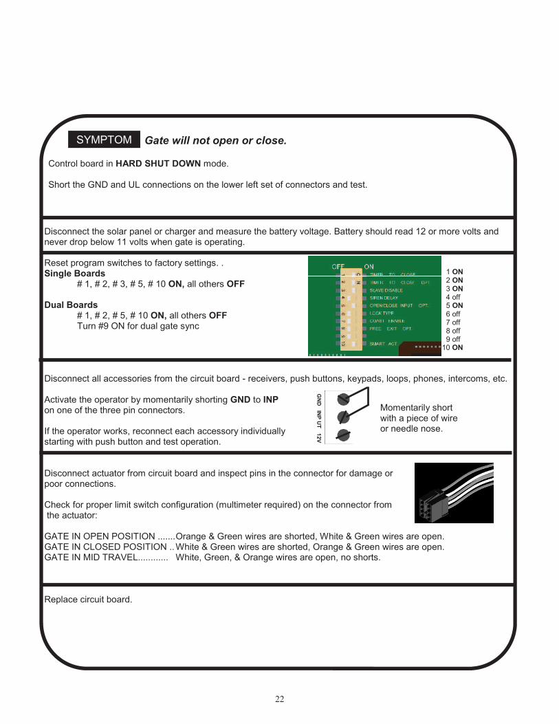
SYMPTOM Gate will not open or close.
Disconnect the solar panel or charger and measure the battery voltage. Battery should read 12 or more volts andnever drop below 11 volts when gate is operating.
Reset program switches to factory settings. .Single Boards
# 1, # 2, # 3, # 5, # 10 ON, all others OFF
Dual Boards# 1, # 2, # 5, # 10 ON, all others OFFTurn #9 ON for dual gate sync
Disconnect all accessories from the circuit board - receivers, push buttons, keypads, loops, phones, intercoms, etc.
Activate the operator by momentarily shorting GND to INPon one of the three pin connectors.
If the operator works, reconnect each accessory individuallystarting with push button and test operation.
Disconnect actuator from circuit board and inspect pins in the connector for damage orpoor connections.
Check for proper limit switch configuration (multimeter required) on the connector from the actuator:
GATE IN OPEN POSITION .......Orange & Green wires are shorted, White & Green wires are open.GATE IN CLOSED POSITION ..White & Green wires are shorted, Orange & Green wires are open.GATE IN MID TRAVEL............ White, Green, & Orange wires are open, no shorts.
Replace circuit board.
1 ON2 ON3 ON
4 off 5 ON 6 off 7 off 8 off
9 off10 ON
GN
D IN
P U
T 1
2V
Momentarily shortwith a piece of wireor needle nose.
Control board in HARD SHUT DOWN mode.
Short the GND and UL connections on the lower left set of connectors and test.

23
LIMITED TWO-YEAR WARRANTY
Apollo Gate Operators are warranted against defects for a period of 24months from the date of purchase, providing recommended installationprocedures are followed. This warranty is in lieu of all other warrantiesexpressed or implied (some states do not allow limitations on how long animplied warranty lasts, so this limitation may not apply to you) and shall beconsidered void if damage was due to improper installation or use, connectionto improper power source, or if damage was caused by fire, flood, or lightning.The manufacturer will not be responsible for any labor charges incurred in theremoval or replacement of defective parts.
In case of failure due to defective material or workmanship during thewarranty period, the defective part will be repaired or replaced at themanufacturer’s option at no charge if returned freight prepaid. New or factoryrebuilt replacements may be used. Replacement parts are warranted for theremaining portion of the original warranty period. The manufacturer will paystandard ground freight on the return of repaired or replaced items in warranty.
APOLLO Gate Operators, Inc.