Embed Size (px)
Citation preview

DMP TYPE POWER BOX EMP TYPE CONTROLLER CSM TYPE CONTROL BOARD
DOUBLE OVEREXCITATION QUADRUPLE OVEREXCITATIONPRINTED CIRCUIT TYPE
Our clutches and brakes used in various equipment including industrial equipment, information equipment and recreation facilities play an important part in automation ormotion control systems in terms of power transmission and control.
The machines shown here are only a sampling of what is available.
ELECTROMAGNETICCLUTCHES AND BRAKES
CONSTANT VOLTAGE/CONSTANT CURRENT POWER SOURCEPS TYPE
ROLL DIAMETER PROPORTIONAL TYPEAUTOMATIC TENSION CONTROL SYSTEMPCD TYPE
MICRO DEVIATIONAUTOMATIC TENSION CONTROL SYSTEMPCF TYPE
POWER BOX AND CONTROLLER
NC SBR SBM ERS BO
ERS
JCC
SBS
AR
SBM
POB
EPR
JCC
SE
SFC
TZ
SBS
EP/EPS
JEP
JEP
NC-T
TB
SBM SBS JC SF TZ
X-ray device
Elevating unitfor stairways
MRI
Welfare vehicle
Conveyor
Crane Forklift
Automated guidedvehicle(AGV)
Labelling device
Mills
Shearing machine
Flying sheu
Press
Rolling mills
Automatic screwcutting lathe
Engine lathe
Machining centerDrilling machine
NC machine tool
Bottle filling machine
Packaging machine
Bag elaborating machine
POB
Machinerytool Steel
Metalprocessing
Wrapping/Packagingmachinery
Transport /DeliverymachineryMedical
Welfareequipment
1609B1○SE70-001CODE
Formerly
Shiba NBF Tower, 1-30, Shiba-daimon 1-chome, Minato-ku, Tokyo, 105-8564, JapanTEL +81-3-5473-1826 FAX +81-3-5473-1845
SINFONIA TECHNOLOGY CO., LTD. continually upgrades and improves its products. Actual features and specifications may therefore differ slightly from those described in this catalog.
96 Robinson Road, #13-02 SIF Building, Singapore 068899TEL +65-6223-6122 FAX +65-6225-2729
Graha Paramita 8th Floor Suite E Jl. Denpasar Raya Block D2 KAV. 8 Kuningan, Jakarta 12940, IndonesiaTEL 021-252-3606 (hunting) FAX 021-252-3608
Room3006, Building B Far East International Plaza, No 317, Xian Xia Road, Changning District, Shanghai, ChinaZip Code:200051TEL +86-21-6275-0606 FAX +86-21-3209-8975
12th Floor Room 1205, 319 Chamchuri S�uare Building, Phayathai Road, Pathumwan Bangkok 10330, ThailandTEL +66-2160-5068 FAX +66-2160-5069
http://www.sinfo-t.jp
For safe and reliable operation, it is essential to read the user,s manual carefullybefore using this equipment.
2007 4A SPrinted in Japan
Our clutches and brakes
used in various equipment including industrial equipment,
information equipment and recreation facilities play
an important part in automation or
motion control systems.
We have a new slogan in Japan; “ECOing” a combination of “eco” and “ing”. This is to promote eco-friendly technological development and manufacturing.Our ecological activities are of course not limited to Japan and practiced in many countries around the world.
This catalogue, passed E3PA standard, is printed in eco-friendly way by using FSC® paper and vegetable oil ink.
天地8mmまで縮小可能

DMP TYPE POWER BOX EMP TYPE CONTROLLER CSM TYPE CONTROL BOARD
DOUBLE OVEREXCITATION QUADRUPLE OVEREXCITATIONPRINTED CIRCUIT TYPE
Our clutches and brakes used in various equipment including industrial equipment, information equipment and recreation facilities play an important part in automation ormotion control systems in terms of power transmission and control.
The machines shown here are only a sampling of what is available.
ELECTROMAGNETICCLUTCHES AND BRAKES
CONSTANT VOLTAGE/CONSTANT CURRENT POWER SOURCEPS TYPE
ROLL DIAMETER PROPORTIONAL TYPEAUTOMATIC TENSION CONTROL SYSTEMPCD TYPE
MICRO DEVIATIONAUTOMATIC TENSION CONTROL SYSTEMPCF TYPE
POWER BOX AND CONTROLLER
NC SBR SBM ERS BO
ERS
JCC
SBS
AR
SBM
POB
EPR
JCC
SE
SFC
TZ
SBS
EP/EPS
JEP
JEP
NC-T
TB
SBM SBS JC SF TZ
X-ray device
Elevating unitfor stairways
MRI
Welfare vehicle
Conveyor
Crane Forklift
Automated guidedvehicle(AGV)
Labelling device
Mills
Shearing machine
Flying sheu
Press
Rolling mills
Automatic screwcutting lathe
Engine lathe
Machining centerDrilling machine
NC machine tool
Bottle filling machine
Packaging machine
Bag elaborating machine
POB
Machinerytool Steel
Metalprocessing
Wrapping/Packagingmachinery
Transport /DeliverymachineryMedical
Welfareequipment
BB
POC
PTB
POC
PTB
PRB-HPRB-H
HO
PMC
TB
ERS EP/EPS JCC JEP
PMC
HO
BO
MP
JC
NC-H
SBR ERS SBM TZ
TZ
Ticket vending machine
Productioninformation terminal
Label printer
Copy machine
Facsimile
Gravure printing machine
Slitter
Offset printer
Laminator
Automatic paperfolding machine
Spool supplyingdevice
Wood cutting machine
Index table
Vending machineElevator
Automatic pipewinding machine Automatic spinning
machine
Pleating
Draw false twisttexturing machine
Painting robot
Carrier robot
Welding robot
Automaticassembling machine
We are an all-around maker of electromagnetic clutches and brakes, amply meeting all kinds of requirements of its customers on a firm technological basis, allowing the development and production of superlative clutches and brakes.
Officeequipment /IT device
Robot /Assemblingmachine
Others
Textilemachinery
Paper processing/printing machinery
For Automation of All Kinds of Mechanisms Electromagnetic Clutches and Brakes
SELC&BDRY, SINGLE-PLATECLUTCHES /BRAKES
Spring drive with auto-gap device.Highly responsive and accurate in action.Distinguished in heat dissipation.Silent construction with no squeal noise.Asbestos-free facing.
SELC&B CLUTCHJC SERIESTHROUGH SHAFT TYPE
SELC&B CLUTCHJCC SERIESSPRIT SHAFT TYPE
SELC&B BRAKEJB SERIES
SELC&B UNITJEP SERIESEASILY MOUNTEDCLUTCH /BRAKE UNIT
WARNER DRY, SINGLE-PLATECLUTCHES/BRAKES
Equipped with an auto-gap device which eliminates the needfor troublesome adjustment during whole life.Extremely accurate; in response and quick permitwide torque control.Large heat-radiation capacity and can withstand exceedinglyfrequent operation and heavy use.Compact and easy to install; long life ensured by theirunique construction and materials.Easy to use and easy to instaII; can be readily mountedon the machine.No need for combination design, machining or centering.Wide variety of compound product series which combine motor,reduction gear, speed change gear, etc. into single units.
WARNER CLUTCHSFC SERIESBUFF SHAFT TYPE
WARNER CLUTCHSF SERIESTHROUGH SHAFT TYPE
WARNER BRAKEPB/RF SERIESFRICTION DISC UNTITEDWITH FIELD
ARM-BRAKEAR SERIESSHAFT MOUNTED BRAKEWITH HOLDING ARM
ELECTRO-SHEAVEES SERIESSHAFT MOUNTED CLUTCHWITH PULLEY
ELECTRO-PACKEP SERIESEASILY MOUNTEDCLUTCH/BRAKE UNIT
CLUTCH-COUPLERCLC SERIESEASILY MOUNTEDCLUTCH UNIT
REVER-PACKRP SERIESNORMAL AND REVERSALDRIVE UNIT WITHBEVEL GEARS
CYCLO-PACKCHHCM SERIESMOTORIZED CLUTCH/BRAKEUNIT WITH CYCROREDUCER
PAN-CAKE TYPEDRY, SINGLE-PLATE CLUTCHES/BRAKES
Very slim type with reduced width.Leaf-spring drive type with quick response and no back-lash.Outstanding durability ensured by a unique clover-shape leaf spring.Easy to install;a variety of convenient multifunction units available.
PAN-CAKE TYPECLUTCHNC SERIES
PAN-CAKE TYPEBRAKENB SERIES
ENGINEDRY, SINGLE-PLATE CLUTCHES/BRAKES
Feature a leaf-spring construction especially developed for engines.Strong against impact loads and vibrations, outstandingin durability and reliability.So compact that little installation space is needed.Coil rest type which requires minimal maintenance and inspection.
ENGINE CLUTCHSF SERIES
MICRODRY, SINGLE-PLATE CLUTCHES/BRAKES
Smallest of all dry, single-disk clutches.Quick in response and extremely accurate;no drag torque.Need no adjustment and maintain stable characteristics for a long time.Feature most suitable for highly frequent operation.
MICRO CLUTCHBO SERIES
MICRO BLAKEBB SERIES
MINI PACKMP SERIESMICRO CLUTCH/BRAKE UNIT
FAIL-SAFE BRAKES/HOLDING BRAKESNon-exciting electromagnetic brakes.ERS series features permanent magnet;SBR is spring-activated.ERS are dry, single-face brakes;SBR are dry, dual-plate brakes.Most suitable as emergency brakes, safety brakes,or holding brakes for motors and robots.
FAIL SAFE BRAKEERS SERIES
SER-PACKEPR SERIESCLUTCH(SFC)/BRAKE(ERS)UNIT
HOLDING BRAKESBR SERIES
DRY TYPE, MULTIPLE-DISCLARGE SIZECLUTCHSE SERIESNON-EXCITING DRIVE TYPEROTATING COIL TYPE
DRY TYPE,MULTIPLE-DISCBRAKESBS SERIESSPRING ENGAGED TYPE
TOOTHED CLUTCHESToothed clutches/brakes small in size yetcapable of transmitting great torque reliably.No drag torque;no drag or heat generationeven under light load.Trapezoidal tooth profile ensures smoothcoupling and outstanding ON /OFFcharacteristics.Single-position type which simplifies couplingat a fixed position.
TOOTHEDCLUTCHTO SERIESSTATIONARY COIL TYPE
TOOTHEDCLUTCHTR SERIESROTATING COIL TYPE
SINGLE-POSITIONCLUTCHSPO SERIESSTATIONARY COIL TYPE
SINGLE-POSITIONCLUTCHTZ SERIESBALL BEARINGATTACHMENT TYPE
SINGLE-POSITIONCLUTCHSTZ SERIESBALL BEARINGATTACHMENT TYPE
HYSTERESISCLUTCHES/BRAKES
Constant in torque regardless ofthe number of slip speed.No shock when coupling; outstandingin torque repeatability.
HYSTERESISCLUTCHHO SERIESSTATIONARY COIL TYPE
HYSTERESISBRAKEHB SERIES
PARTICLECLUTCHES/BRAKES
Permit wide-range, high-accuracy torquecontrol through current control.Outstanding in response and highest in constant-torque characteristic regardless of slip speed.Available in continuous slip operation and mostsuitable for highly frequent operation.Long life because of their excellent durability.No shock when coupling or braking;outstanding in torque repeatability.
PARTICLE CLUTCHPOC SERIESNATURAL COOLINGWITH SHAFT
PARTICLE CLUTCHPHC-R SERIESSELF-VENTILATIONWITH HOLLOW SHAFT
MICRO TYPEPARTICLE CLUTCHPMC SERIESSTATIONARY COIL
PARTICLE BRAKEPOB SERIESNATURAL COOLINGWITH SHAFT
PARTICLE BRAKEPHB SERIESNATURAL COOLINGWITH HOLLOW SHAFT
PARTICLE BRAKEPRB-H SERIESNATURAL COOLING BRAKE(WITH SIDE FIN)
TENSION BRAKESIncorporate a friction disk and an armaturefor slip service.Feature great durability and fully withstandcontinuous slip service.Permit wide-range torque control, and hencehighly accurate control.Various types of control systems available sothat outstanding tension control systemscan be designed.
TENSION BRAKETB SERIESPIN DRAIVE TYPEOPTIMUM FORWINDING BRAKE
DRY TYPEMULTIPLE-DISCCLUTCHES/BRAKES
Small in size, yet large in torque capacity.Most suitable for cases where clutch/brakeinstallation space is limlited.Most suitable for cases where clutch /brakedimensions are limited.
Rated Torque: 6~400Nm
Rated Torque:1250~16600Nm
Rated Torque: 6~400Nm
SELC&B UNITWITH MOTORJEM SERIES
Rated Torque: 6~50Nm
Rated Torque:7~1800Nm
Rated Torque:7~1800Nm Rated Torque:
7~1800Nm
Rated Torque:7~180Nm
Rated Torque:70~650Nm
Rated Torque:3~200Nm
Rated Torque:130~3000Nm
Rated Torque:3~200Nm
Rated Torque:7~1800Nm
Rated Torque:15~1500Nm
DRY TYPE,MULTIPLE-DISCBRAKESBM SERIESSPRING ENGAGED TYPE
Rated Torque:2~37Nm
Rated Torque:20~800Nm
Rated Torque:20~50000Nm
Rated Torque:63~400Nm
Rated Torque:63~1600Nm
Rated Torque:0.06~1Nm
Rated Torque:0.06~1Nm
Rated Torque:3~800Nm
Rated Torque:6~200Nm
Rated Torque:1~4Nm
Rated Torque:3~800Nm
Rated Torque:6~200Nm
Rated Torque:12~200Nm
Rated Torque:3~380Nm
PARTICLE BRAKEPTB SERIESHEAT PIPE COOLING TYPE
Rated Torque:25~200Nm
Rated Torque:20~800Nm
Rated Torque:0.25~15Nm
Rated Torque:0.25~15Nm Rated Torque:
0.5~15Nm
Rated Torque:2~350Nm Rated Torque:
7~650Nm
Rated Torque:0.3~53Nm
Rated Torque:7~1800Nm Rated Torque:
7~28NmMotor Capacity:
0.2~7.5kW
Rated Torque: 6~400Nm
Rated Torque: 6~400Nm
MICRO TYPEPARTICLE BRAKEPMB SERIESSTATIONARY COIL
Rated Torque:0.5~2Nm
Warner Dry, Single-face Clutches/Brakes
FEATURES
MODELS NAMES
Warner Clutches/Brakes are the most popular lineof Electro-magnetic clutches/brakes now used inlarge numbers in a wide variety of machines innumerous industries. Typical models of dry, single-face design, they have many importantperformance and structural features. Easily usedand installed, they can suit various applicationsinvolving operations ranging from simple startingand stopping to reversing, branch driving,positioning, including, speed variation, andintermittent tunning, in which they are especiallyserviceable when the running frequency is high.They come in end-to-end shaft, through shaft, andother standard types, plus a vriety of easily-usedunits including Electro-Pack clutch/brake units,Clutch-Coupler clutch units, and Electro-Sheaveclutches with V pulleys.
All models incorporate an "auto-gap" mechanism for automaticadjustment. Friction disk wear does not necessitate arduousgap adjustment.
1 No post-installation adjustment is required
A unique armature design enables frictional heat to bequickly released outside. This makes the unit serviceablein high-frequency on-off operations and under demandingservice conditions.
3 High heat release efficiency
Torque can be varied over a wide range by varying thecurrent. This makes possible such operations as slowstarting, braking, and slipping for tension control.
4 Broad freedom in torque control
Taper lock bushing is used to facilitate the assembly of theunit on the shaft and preclude loosening.
2 Easily assembled
Compact and lightweight, the unit takes up only aminimum of space, and can be mounted with ease.
5 Compact, lightweight, easily mounted
Made of choice materials and carefully designed, the unitstays very long in service while long maintaining its initialperformance characteristics, and consumes only aminimum of power.
6 Durable, and economical in power consumption
A wide variety of units are available to be readily used inautomated machines.
7 An extensive line of units available
Models in clutch/brake series Nominal number Armature drive and fieldmounting types
SF: Through shaft clutchSFC: End-to-end shaft clutchRF: Brake with replaceable
friction diskPB/PBS: Brake with integrated
field-friction diskEP/EPS: Clutch/brake unitCLC: Clutch unitES: Clutch unit with pulleyAR: Brake unit with holding armRP: Reversible drive unit
BMS: Spline-drive, ball bearing-mounted typeBMP: Pin-drive, ball bearing-mounted typeFMS: Spline-drive, flange-mounted typeIMS: Spline-drive, inside-mounted type IMP: Pin-drive, inside-mounted type
HT suffixed to a number stands for"high torque".
Formerly SHINKO ELECTRIC CO., LTD.
DE71 ]100 @new ˛ ¯ .qxd:DE71 ]100.qxd 15/09/08 15:54 y [ W 1

How to Select Warner Clutch/Brake Models (Simplified Model Selection Tables)
2
Clutch operating modes may bedivided into two types: The maximum torque is applied tothe system after it has been startedfully (for example, in a lathe, on whichthe work begins to be ground after itsrotation has reached the regularspeed).
The maximum torque is appliedwhen the clutch is actuated(forexample, in a conveyor system, inwhich case the load is already on thesystem when the clutch closes).By referring to Table I or II, it is easyto select the right clutch model for aparticular application from the motorcapacity and the clutch shaft speedinvolved.
If you are not sure which type ofclutch operating mode is expected,use Table II.If you have a brake in mind, use Table I.If the application you have in mindinvolves a high load GD2 or highactuating frequency or high turningspeed, ask the manufacturer for arecommendation.
Selection Table I Maximum Torque Is Applied After System Has Fully Been Started
Selection Table II Maximum Torque Is Applied When System Is Started
0.015 (kW)0.0350.0650.10.1250.20.25 0.40.550.751.11.52.23.75.57.5
11151922303745557592
110
1/50 (HP)1/301/121/81/51/41/31/23/4
11 1/22357 1/2
101520253040 506075
100125150
rpmMotor capacity 100 200 300 400 500 600 700 800 900 1000 1100 1200 1500 1800 2000 2400 3000 3600 4000 4600 5000
When an opticl-waveguide cable is laid, the individual fibers have to be spliced together.
0.015 (kW)0.0350.0650.10.1250.20.25 0.40.550.751.11.52.23.75.57.5
1115192230
1/50 (HP)1/201/121/81/61/41/31/23/4
11 1/22357 1/2
101520253040
rpmMotor capacity 100 200 300 400 500 600 700 800 900 1000 1100 1200 1500 1800 2000 2400 3000 3600 4000 4600 5000
The picture shows a multiple splicer with fibers spliced in pairs by means of an AC arc.
250400400400400500500650825
10001000122512251525
1525HT1525HT
250250250400400400400500650650825
10001000122512251525
1525HT1525HT
250250250250400400400500500650650825
100010001225122515251525
1525HT1525HT
160250250250250400400400500500650650825
100010001225122515251525
1525HT1525HT
160250250250250400400400500500650650650825
100010001225122515251525
1525HT1525HT
160250250250250250400400400500500650650825
1000100012251225122515251525
1525HT1525HT
160250250250250250250400400500500650650650825
100010001225122512251525
1525HT1525HT
160160250250250250250400400400500500650650825
1000100012251225122515251525
1525HT1525HT
160160250250250250250400400400500500650650650825
1000100012251225152515251525
1525HT
160160250250250250250400400400500500650650650825
1000100012251225122515251525
1525HT1525HT
160160250250250250250400400400500500500650650825
1000100010001225122515251525
1525HT1525HT
160160250250250250250400400400400500500650650825
10001000100012251225122515251525
1525HT1525HT
160160160250250250250400400400400400500500650650825
1000100010001225122512251525
1525HT1525HT1525HT
160160160250250250250250400400400400500500650650650825
1000100010001225122512251525
1525HT1525HT
160160160160250250250250400400400400500500650650650825
100010001000122512251225
160160160160250250250250250400400400400500500650650650825
10001000100012251225
160160160160160250250250250400400400400400500500650650825825
100010001000
160160160160160250250250250250400400400400500500650650650825825
160160160160160160250250250250400400400400500500500
160160160160160160250250250250
160160160160160160250250250250
250400400400500500500650825
10001225122515251525
1525HT1525HT
250250400400400400500650650825
100010001225122515251525
1525HT1525HT
250250250400400400400500650650825825
1000122512251225
1525HT1525HT1525HT
160250250400400400400500500650650825
10001000122512251525
1525HT1525HT1525HT
160250250250400400400500500500650650825
1000100012251225
1525HT1525HT1525HT
160250250250250400400400500500650650825
10001000122512251525
1525HT1525HT1525HT
160250250250250400400400500500650650825825
1000100012251525
1525HT1525HT1525HT
160250250250250400400400400500650650650825
1000100012251525
1525HT1525HT1525HT
160250250250250250400400400500500650650825
1000100012251525
1525HT1525HT1525HT
160160250250250250400400400500500500650825
1000100012251225
1525HT1525HT1525HT
160160250250250250250400400500500500650825
1000100012251225
1525HT1525HT1525HT
160160250250250250250400400400500500650825
10001000122512251525
1525HT1525HT
160160250250250250250400400400500500650825825
1000122512251525
1525HT1525HT
160160250250250250250400400400500500650650825
1000122512251525
1525HT1525HT
160160160250250250250400400400500500500650825
100012251225
160160160250250250250400400400400500500650825
100012251225
160160160250250250250250400400400400500650825
1000
160160160160250250250250400400400400500650825
160160160160250250250250400400400400500
160160160160250250250250
160160160160250250250250
DE71 ]100 @new ˛ ¯ .qxd:DE71 ]100.qxd 15/09/08 15:54 y [ W 2

Warner Clutches (End-to-End Shaft Type), SFC Series
3
Have high power capacity, andtolerate high-frequency actuation.End-to-end shaft design.
M daoLroto
ModelD
raw
ing
num
ber Static
frictiontorque(Nm)
Outside dimensions (mm)Ratedvoltage(DC-V)
Powerconsumptionat 75
(W)
Weight
(kg) dLD
SFC-250/BMS-AG
SFC-250/FMS-AG
SFC-400/BMS-AG
SFC-400/FMS-AG
SFC-500/BMP
SFC-501/BMS
SFC-650/IMS
SFC-650/BMS
SFC-825/IMS
SFC-825/BMS
SFC-1000/IMS
SFC-1000/BMS
SFC-1225/IMS
SFC-1225/BMS
SFC-1525/IMS
SFC-1525/BMS
SFC-1525HT/IMS
SFC-1525HT/BMS
A
A
A
A
D
A
B
C
B
C
B
C
B
C
B
C
B
C
7
7
28
28
70
70
130
130
180
200
350
350
650
650
1000
1000
1800
1800
24
24
24
24
24
24
24
24
24
24
24
24
24
24
24
24
24
24
7
7
8
8
23
23
26
26
25
28
31
31
27
27
32
32
143
143
67
67
108
108
135
135
169.5
169.5
218
218
262
262
322.5
322.5
398
398
400.8
400.8
55.3
50.5
67
59.3
95.5
83.2
92
124
105.5
108.1
134.9
168.9
148.1
188.1
150.9
186.9
184
200.7
12
12
18
18
28
28
28
28
28
28
48
48
50
50
50
50
75
75
0.77
0.75
2.3
2.3
4.0
4.1
6.6
7.9
11
11
19
21
32
36
44
54
51
61
L
A
Dφd
D
φd
L
B
L
D
C
φd
L
φd D
D
DE71 ]100 @new ˛ ¯ .qxd:DE71 ]100.qxd 15/09/08 15:54 y [ W 3

Warner Clutches (Through Shaft Type), SF Series
4
Have high power capacity, andtolerate high-frequency actuation.Through-shaft design.
Model
Dra
win
gnu
mbe
r Staticfrictiontorque(Nm)
Outside dimensions (mm)Ratedvoltage(DC-V)
Powerconsumptionat 75
(W)
Weight
(kg) dLDSF-250/BMS-AGSF-250/FMSSF-250/BMGSF-250/FMGSF-400/BMS-AGSF-400/FMSSF-400/BMGSF-400/FMGSF-500/BMPSF-501/BMSSF-650/IMSSF-650/IMPSF-650/BMSSF-650/BMPSF-825/IMSSF-825/IMPSF-825/BMSSF-825/BMPSF-1000/IMSSF-1000/IMPSF-1000/BMSSF-1000/BMPSF-1225/IMSSF-1225/IMPSF-1225/BMSSF-1225/BMPSF-1525/IMSSF-1525/IMPSF-1525/BMSSF-1525/BMPSF-1525HT/IMSSF-1525HT/BMS
A A B B A A B B F E C D E D C D E D C D E D C D E D C D E D C D
7777
282828 287070
130130130130180180200200350350350350650650650650
100010001000100018001800
2424242424242424242424242424242424242424242424242424242424242424
77778888
23232626262625252828313131312727272732323232
143143
67676767
108108108108135135169.5169.5169.5169.5218218218218262262262262322.5322.5322.5322.5398398398398400.8400.8
8581.554.349.596.78964.356.496.578.29363
1259591.463.594.366.493.164.3
127.198.3
109.275.4
149.2114.6112
75.4148111.4147.3164
1212121218181818282828282828282828284848484850505050505050507575
0.790.770.770.752.42.32.32.33.53.86.45.97.76.2
119.0
119.9
1715191731253429433448434959
Load
Motor
φd D
AL
φd D
L
B
D
L
φd
C
φdD
L
D
L
Dφd
E
F
L
Dφd
DE71 ]100 @new ˛ ¯ .qxd:DE71 ]100.qxd 15/09/08 15:54 y [ W 4

Warner Brakes (with ReplaceableFriction Disk), RF Series
5
Warner Brakes (with IntegratedField-Fiction Disk), PB Series
Warner Brakes, RF Series
Warner Brakes, PB/PBS Series
ModelD
raw
ing
num
ber Static
frictiontorque(Nm)
Outside dimensions (mm)Ratedvoltage(DC-V)
Powerconsumptionat 75
(W)
Weight
(kg) dLDRF-250/FMS-AGRF-400/FMS-AGRF-825/IMSRF-825/IMPRF-1000/IMSRF-1000/IMPRF-1225/IMSRF-1225/IMPRF-1525/IMSRF-1525/IMPRF-1525HT/IMS
A A B C B C B C B C B
728
180180350350650650
100010001800
2424242424242424242424
78
2525313127273232
143
67108218218262262322.5322.5398398400.8
5059.281.3
104110.1112.7121.4151.6121.4126.2119.2
1218282848485050505075
0.652.09.0
10.516152529.53338.538
Model
Dra
win
gnu
mbe
r Staticfrictiontorque(Nm)
Outside dimensions (mm)Ratedvoltage(DC-V)
Powerconsumptionat 75
(W)
Weight
(kg) dLDPB-260/FMS-AGPB-400/FMS-AGPB-500/IMPPB-501/IMSPB-650/IMSPB-650/IMPPBS-825/IMSPBS-825/IMPPB-1000/IMSPB-1000/IMPPB-1225/IMSPB-1225/IMPPB-1525/IMSPB-1525/IMP
A A F D D F D E D E D E D E
7285555
130130180180350350650650
10001000
2424242424242424242424242424
9.78
212121213030272722222525
68102128.6134164165218218262262320320394394
50527461.557.47169.992.697.7
100.3104.2134.4107.4112.2
1218282828282828484850505050
0.551.32.72.64.75.06.97.3
121119202627
Load
Motor
High braking torque. Distinguisheddurability. Replaceable friction disk.
Load
Motor
Dφd
A
L
B
L
Dφd
C
L
Dφd
D
L
Dφd
E
L
Dφd
F
L
Dφd
Integrated field-friction disk.Easily-mounted, universal, low-costtype.
DE71 ]100 @new ˛ ¯ .qxd:DE71 ]100.qxd 15/09/08 15:55 y [ W 5

Electro-Pack Clutch/Brake Units, EP/EPS Series
6
Compact double-shaft unitsincorporating a Warner clutch/brake.Carefully centered at the factory, theyonly need lead connections at theinstallation site.
ModelStaticfrictiontorque
(Nm)
Ratedvoltage(DC-V)
Powerconsumptionat 75
(W)
Outside dimensions (mm) Weight
(kg)3.0
8.8
13
14
42
60
100
150
213
270
13
19
22
22
28
28
48
50
50
75
225
298
394
375
448
524
620
676
708
830
117
175
202.5
202.5
235
264
312
372
452
461
79.788
2321232126212530312727223225
143143
24
24
24
24
24
24
24
24
24
24
77
282870557055
130130180180350350650650
1000100018001800
EP-250
EP-400
EP-500
EP-501
EPS-650
EP-825
EPS-1000
EPS-1225
EPS-1525
EPS-1525HT
D L d
L
D
φd
Note: In the above table, static friction torque and power consumption data consists ofclutch (top) and brake (bottom) values.
Clutch-Coupler Cluch Units, CLC Series
Designed for easy magnetic clutchinstallation. Only lead connections arerequired after the driving and drivenshafts are coupled.
L
D
φd
ModelStaticfrictiontorque
(Nm)
Ratedvoltage(DC-V)
Powerconsumptionat 75
(W)
Outside dimensions (mm) Weight
(kg)2.4
6.0
16
46
82
118
180
203
13
19
22
28
48
50
50
75
198
264
352
460
553
610
638
682
117
175
204.5
264
312
372
452
461
7
8
23
25
31
27
32
143
24
24
24
24
24
24
24
24
7
28
70
180
350
650
1000
1800
CLC-250
CLC-400
CLC-501
CLC-825
CLC-1000
CLC-1225
CLC-1525
CLC-1525HT
D L d
DE71 ]100 @new ˛ ¯ .qxd:DE71 ]100.qxd 15/09/08 15:55 y [ W 6

Electro-Sheave Clutch Units with V Pulley, ES Series
7
Integrated Warner clutch-V pulleyunits. Only a wrench is required toinstall an ES on any machine. Nodesigning, machining, or centering isrequired.
155155155135170192248
19242828383842
100150150150150200236
ModelStaticfrictiontorque
(Nm)
Ratedvoltage(DC-V)
Powerconsumptionat 75
(W)
Outside dimensions (mm) Weight
(kg)6.38.58.5
17233551
135135135218218262322.5
23232328283127
24242424242424
707070
200200350650
ES-500-A2-19JES-500-B2-24JES-500-B2-28JES-825-B2-28JES-825-B4-38JES-1000-B4-38JES-1225-C3-42J
D L d RL
DφdR
Brake Units with Holding Arm, Series AR
An arm and a rod are provided toenable the unit to be installed easilyeven where no frame is available tofix it to. Just key the rotary shaft. Noadjustment is required.
L
Dφd
476081.495
12182830
124192265295
ModelStaticfrictiontorque
(Nm)
Ratedvoltage(DC-V)
Powerconsumptionat 75
(W)
Outside dimensions (mm) Weight
(kg)0.782.15.5
10.9
67108136218
78
2330
24242424
72870
180
AR-250AR-400AR-500AR-825
D L d Y
Rever-Pack Reversible Drive Units, RP Series
A bevel gear-clutch combination isincorporated in a compact unitoffering superb performance inreversible or reciprocating operationsin various machines.
ModelStaticfrictiontorque(kgm)
Ratedvoltage(DC-V)
Powerconsumptionat 75
(W)
Outside dimensions (mm) Weight
(kg)5.0
15180260
78
2424
728
RP-250RP-400
D188255
L1116
d138200
H71
100
CL
D
H
C
φd
DE71 ]100 @new ˛ ¯ .qxd:DE71 ]100.qxd 15/09/08 15:55 y [ W 7

Cyclopack: Drive Units with Clutches/Brakes and Reduction Gear
"Cyclopacks" are a completely new type of drive units consisting of Warner Clutches/Brakesreputed for their contribution to automation and high efficiency combined with Sumitomo"Cyclo" Reduction Gear known as top-quality products in the industry into compactassemblies which in their turn are integrated with standard motors.
Model: CHHCM 3-phase squirrel-cage motors
Motor Capacity: 0.2-7.5 kW Electro magnetic clutches/brakes
Static torque: 6-180 Nm
’ P S N F S M Z
Shiba NBF Tower, 1-30, Shiba-daimon 1-chome, Minato-ku, Tokyo, 105-8564, JapanTEL +81-3-5473-1826 FAX +81-3-5473-1845
SINFONIA TECHNOLOGY CO., LTD. continually upgrades and improves its products. Actual features and specifications may therefore differ slightly from those described in this catalog.
101 Cecil Street #13-12 Tong Eng Building Singapore 069533TEL +65-6223-6122 FAX +65-6225-2729
Graha Paramita 8th Floor Suite E Jl. Denpasar Raya Block D2 KAV. 8 Kuningan, Jakarta 12940, IndonesiaTEL: 021-252-3606 (hunting) FAX: 021-252-3608
Room3006, Building B Far East International Plaza, No 317, Xian Xia Road, Changning District, Shanghai, ChinaZip Code:200051TEL +86-21-6275-0606 FAX +86-21-3209-8975
1409E71-100CODE
We have a new slogan in Japan; “ECOing” a combination of “eco” and “ing” . This is to promote eco-friendly technological development and manufacturing. Our ecological activities are of course not limited to Japan and practiced in many countries around the world.
http://www.sinfo-t.jp
For safe and reliable operation, it is essential to read the user ,s manual carefullybefore using this equipment.
DE71 ]100 @new ˛ ¯ .qxd:DE71 ]100.qxd 15/09/08 15:55 y [ W 8
Formerly
Shiba NBF Tower, 1-30, Shiba-daimon 1-chome, Minato-ku, Tokyo, 105-8564, JapanTEL +81-3-5473-1826 FAX +81-3-5473-1845
SINFONIA TECHNOLOGY CO., LTD. continually upgrades and improves its products. Actual features and specifications may therefore differ slightly from those described in this catalog.
96 Robinson Road, #13-02 SIF Building, Singapore 068899TEL +65-6223-6122 FAX +65-6225-2729
Graha Paramita 8th Floor Suite E Jl. Denpasar Raya Block D2 KAV. 8 Kuningan, Jakarta 12940, IndonesiaTEL: 021-252-3606 (hunting) FAX: 021-252-3608
Room3006, Building B Far East International Plaza, No 317, Xian Xia Road, Changning District, Shanghai, ChinaZip Code:200051TEL +86-21-6275-0606 FAX +86-21-3209-8975

SHINKO ELECTRIC CO., LTD.Please note that our former company name or logo may be printed in this catalog.
Our
E71-120CODE
Formerly
Shiba NBF Tower, 1-30, Shiba-daimon 1-chome, Minato-ku, Tokyo, 105-8564, JapanTEL +81-3-5473-1826 FAX +81-3-5473-1845
SINFONIA TECHNOLOGY CO., LTD. continually upgrades and improves its products. Actual features and specifications may therefore differ slightly from those described in this catalog.
96 Robinson Road, #13-02 SIF Building, Singapore 068899TEL +65-6223-6122 FAX +65-6225-2729
Graha Paramita 8th Floor Suite E Jl. Denpasar Raya Block D2 KAV. 8 Kuningan, Jakarta 12940, IndonesiaTEL: 021-252-3606 (hunting) FAX: 021-252-3608
Room3006, Building B Far East International Plaza, No 317, Xian Xia Road, Changning District, Shanghai, ChinaZip Code:200051TEL +86-21-6275-0606 FAX +86-21-3209-8975
http://www.sinfo-t.jp
For safe and reliable operation, it is essential to read the user,s manual carefullybefore using this equipment.
2007 4A SPrinted in Japan
Our clutches and brakes
used in various equipment including industrial equipment,
information equipment and recreation facilities play
an important part in automation or
motion control systems.
We have a new slogan in Japan; “ECOing” a combination of “eco” and “ing” . This is to promote eco-friendly technological development and manufacturing. Our ecological activities are of course not limited to Japan and practiced in many countries around the world.
SHINKO ELECTRIC CO., LTD.Please note that our former company name or logo may be printed in this catalog.
Formerly SHINKO ELECTRIC CO., LTD.
Formerly SHINKO ELECTRIC CO., LTD.

A truly state of the art product whose performance and reliability sets it apart from other electromagnetic clutches/brakes. Through the use of our revolutionary "zero backlash auto gap technology" we are able to achieve unparalleled precision and operating life in an easily implemented dry-type single-plate driving electromagnetic clutches/brakes. Additionally, we have included innovations such as an asbestos-free facing on the friction plate, which meets and exceeds expectations with superior motion control performance. Our customer satisfaction thus far has been overwhelmingly positive.
Features1. Driven by a leaf spring with an integrated automatic gap adjustment Our original auto gap equipment experiences no backlash and does not require adjustment.*PATENT NO 1538370.
2. Rapid response and precise operationIdeal torque is immediately achieved by utilizing "a high efficiency magnetic circuit".
3. Excellent thermal radiation capabilityWe have increased the radiation capability by more than several 10% by including a radial fan with a large airflow rate flange.
4. Silent, vibration-free housingBy using a silent, composite plate housing, we were able to prevent unnecessary vibrations, allowing for silent operation.
5. Asbestos-Free FacingAbrasion resistance is increased 30% with a safe, asbestos-free facing.
6. Free mounting orientationYou are able to mount it vertically, horizontally or on an incline.
Dry Type Single-discElectromagneticClutches/Brakes
SELC&B
Models Names
List of Models
JC-0.6Nominal number
Model symbolJC: Clutch, through shaft typeJCC: Clutch, sprit shaft typeJB: Brake, with integrated field-friction disc typeJEP: Clutch/brake unitJEM: Clutch/brake unit with motor
TypeClutch
Appearance
Type
Appearance
Brake
Clutch/brake unit Clutch/brake unitwith motor
JCThrouh saft type
JCCSprit saft type
JEPThrouh saft type JEM
JB
1 2

3 4
StructureSingle Unit
Clutch
Brake
Torque arm
Brake
Field
Coil
Rotor (Silent construction)
Constant-load type wave spring (High-response, high-balance)
Spring pin (For backlashless auto-gap system)
Bolt (For backlashless auto-gap system)
Outer hub (With self cooling
radial fan)
Inner hub
Constant-load type wave spring (High-response, high-balance)
Spring pin (For backlashless auto-gap system)
Bolt (For backlashless auto-gap system)
Outer hub (With self cooling
radial fan)
Inner hub
Distance collar
Facing (Non-asbestos)
Armature (Silent construction)
Magnet
Coil
Facing (Non-asbestos)
Armature (Silent construction)
Clutch & Brake Unit
JEP
JEM
ArmatureMagnet
BrakeArmature
Magnet
Output shaft
Output shaft
Armature
RotorField
Clutch
ArmatureRotorField
Clutch
Input shaft
Motor

5 6
CIutch or Brake Selection GuideClutch operating modes may be divided into two types: The maximum torque is applied to the system after it has been started fuIIy (for example, in a lathe, on which the work begins to be ground after its rotation has reached the normal speed).The maximum torque is applied when the clutch is actuated (for example, in a conveyor system, in which case the load-is already on the system when the clutch closed).
By referring to Table I or II, it is easy to select the right clutch model for a paticular application from the motor capacity and the clutch shaft speed involved. If you are not sure which type of clutch operating mode is expected, use Table I. If you have a brake in mind, use Table I.
Selection Table I Maximum torque is applied after sysem has fully been started
Selection Table II Maximum torque is applied when sysem is started
The explanation of the Auto-gap function[Off time (Power is cut off)]This should cause the back side of armature to be attracted to Hub outer side. In this time, the air-gap between A-part and B-part is adjusted by Auto-gap function, also the air-gap between the armature and the frictional face of rotor is kept the same air-gap.
[On time]This should cause the armature to be attracted to the frictional face of the rotor. The torque of the electromagnetic clutch/brake will be supplied. In this time, the Hub outer will be attracted to the friction face. However, Hub outer is sustained at the same position by spring pin, AG-bush. and the air-gap between A-part and B-part is Zero, lightly contacted. After power is cut off, this should cause the armature to leave by spring, come back to the status Figure 1.
[On Auto-gap adjustment]As the frictional face is loosened by usage, beyond the specified Air-gap. The A-part and the B-part is strongly touched, hub outer is attracted to the friction face by the AG-volt. In this time, Hub outer is moved to the rotor side slightly within the frictional face loosened. In this result, Air-gap is kept with the specified gap automatically.
Figure 1: The status of non-excitation
Figure 2: The status of excitation
Figure 3: The status of Auto-gap adjustment
B-partA-part
Gap 0.4-0.5Gap 0.4-0.5
RotorArmature
Plate springAG bolt
Outer hub
AG bushSpring pin
O ring
Inner hub
Gap zero
Gap zero
r/minMotor power 100 200 300 400 500 600 700 800 900 1000 1100 1200 1500 1800 2000 2400 3000 3600 4000 4600 5000
kW HP0.015 1/50 0.6 0.6 0.6 0.6 0.6 0.6 0.6 0.6 0.6 0.6 0.6 0.6 0.6 0.6 0.6 0.6 0.6 0.6 0.6 0.6 0.60.035 1/20 1.2 0.6 0.6 0.6 0.6 0.6 0.6 0.6 0.6 0.6 0.6 0.6 0.6 0.6 0.6 0.6 0.6 0.6 0.6 0.6 0.60.065 1/12 2.5 1.2 0.6 0.6 0.6 0.6 0.6 0.6 0.6 0.6 0.6 0.6 0.6 0.6 0.6 0.6 0.6 0.6 0.6 0.6 0.60.1 1/8 2.5 1.2 1.2 0.6 0.6 0.6 0.6 0.6 0.6 0.6 0.6 0.6 0.6 0.6 0.6 0.6 0.6 0.6 0.6 0.6 0.6
0.125 1/5 5 2.5 1.2 1.2 0.6 0.6 0.6 0.6 0.6 0.6 0.6 0.6 0.6 0.6 0.6 0.6 0.6 0.6 0.6 0.6 0.60.2 1/4 5 2.5 2.5 1.2 1.2 1.2 1.2 0.6 0.6 0.6 0.6 0.6 0.6 0.6 0.6 0.6 0.6 0.6 0.6 0.6 0.6
0.25 1/3 10 5 2.5 2.5 1.2 1.2 1.2 1.2 1.2 0.6 0.6 0.6 0.6 0.6 0.6 0.6 0.6 0.6 0.6 0.6 0.60.4 1/2 10 5 5 2.5 2.5 2.5 2.5 1.2 1.2 1.2 1.2 1.2 1.2 0.6 0.6 0.6 0.6 0.6 0.6 0.6 0.6
0.55 3/4 20 10 5 5 5 2.5 2.5 2.5 2.5 2.5 1.2 1.2 1.2 1.2 1.2 0.6 0.6 0.6 0.6 0.6 0.60.75 1 20 10 10 5 5 5 5 2.5 2.5 2.5 2.5 2.5 1.2 1.2 1.2 1.2 0.6 0.6 0.6 0.6 0.61.1 1 1/2 40 20 10 10 10 5 5 5 5 5 2.5 2.5 2.5 2.5 2.5 1.2 1.2 1.2 1.2 0.6 0.61.5 2 40 20 20 10 10 10 10 5 5 5 5 5 2.5 2.5 2.5 2.5 1.2 1.2 1.2 1.2 1.22.2 3 40 20 20 20 10 10 10 10 10 5 5 5 5 5 2.5 2.5 2.5 2.5 1.2 1.23.7 5 40 40 20 20 20 20 10 10 10 10 10 5 5 5 5 2.5 2.5 2.5 2.55.5 7 1/2 40 40 40 20 20 20 20 20 20 10 10 10 10 5 5 57.5 10 40 40 40 40 20 20 20 20 20 10 10 10 10 5 511 15 40 40 40 40 40 40 20 20 20 20 10 1015 20 40 40 40 40 40 20 20 20 20 1019 25 40 40 40 40 40 20 2022 30 40 40 40 40 2030 40 40 40 4037 50 40
r/minMotor power 100 200 300 400 500 600 700 800 900 1000 1100 1200 1500 1800 2000 2400 3000 3600 4000 4600 5000
kW HP0.015 1/50 0.6 0.6 0.6 0.6 0.6 0.6 0.6 0.6 0.6 0.6 0.6 0.6 0.6 0.6 0.6 0.6 0.6 0.6 0.6 0.6 0.60.035 1/20 1.2 0.6 0.6 0.6 0.6 0.6 0.6 0.6 0.6 0.6 0.6 0.6 0.6 0.6 0.6 0.6 0.6 0.6 0.6 0.6 0.60.065 1/12 2.5 1.2 1.2 0.6 0.6 0.6 0.6 0.6 0.6 0.6 0.6 0.6 0.6 0.6 0.6 0.6 0.6 0.6 0.6 0.6 0.60.1 1/8 2.5 2.5 1.2 1.2 1.2 0.6 0.6 0.6 0.6 0.6 0.6 0.6 0.6 0.6 0.6 0.6 0.6 0.6 0.6 0.6 0.6
0.125 1/5 5 2.5 2.5 1.2 1.2 1.2 0.6 0.6 0.6 0.6 0.6 0.6 0.6 0.6 0.6 0.6 0.6 0.6 0.6 0.6 0.60.2 1/4 5 5 2.5 2.5 2.5 1.2 1.2 1.2 1.2 1.2 1.2 0.6 0.6 0.6 0.6 0.6 0.6 0.6 0.6 0.6 0.6
0.25 1/3 10 5 5 2.5 2.5 2.5 1.2 1.2 1.2 1.2 1.2 1.2 0.6 0.6 0.6 0.6 0.6 0.6 0.6 0.6 0.60.4 1/2 10 10 5 5 5 2.5 2.5 2.5 2.5 2.5 2.5 1.2 1.2 1.2 1.2 1.2 0.6 0.6 0.6 0.6 0.6
0.55 3/4 20 10 10 5 5 5 5 2.5 2.5 2.5 2.5 2.5 2.5 1.2 1.2 1.2 1.2 1.2 0.6 0.6 0.60.75 1 20 20 10 10 5 5 5 5 5 5 5 2.5 2.5 2.5 2.5 1.2 1.2 1.2 1.2 1.2 1.21.1 1 1/2 40 20 20 10 10 10 10 10 5 5 5 5 5 2.5 2.5 2.5 2.5 2.5 1.2 1.2 1.21.5 2 40 40 20 20 10 10 10 10 10 10 10 5 5 5 5 5 2.5 2.5 2.5 2.5 2.52.2 3 40 40 20 20 20 20 10 10 10 10 10 10 5 5 5 5 5 2.5 2.5 2.53.7 5 40 40 40 20 20 20 20 20 20 20 10 10 10 10 10 5 55.5 7 1/2 40 40 40 40 40 40 20 20 20 20 20 10 10 107.5 10 40 40 40 40 40 40 40 20 20 20 20 1011 15 40 40 40 40 40 2015 20 40 40

7 8
CharacteristicsHeat Dissipation CapacityRelative Speed vs. Torque
Response Characteristics
Description 0.6 1.2 2.5 5 10 20 40
Armature pull-in timeta (ms)
DC24V Excitation
Nominalnumber
Excitin voltage
25 35 45 65 90 110 130
2-Hold over excitaion 10 15 20 30 40 50 70
4-Hold over excitation 8 8 10 15 20 25 35
Torque build-up timetp (ms)
DC24V Excitation 50 70 90 130 160 200 250
2-Hold over excitaion 25 35 50 70 90 120 160
4-Hold over excitation 15 20 25 35 45 60 80
Torque decay timetd (ms)
DC24V Excitation
20 30 35 45 80 110 1402-Hold over excitaion
4-Hold over excitation
Relative rotation (r/min)
To
rqu
e (N
m)
Rotation (r/min)
Hea
t d
issi
pat
ion
cap
acit
y (W
)
Total life/Max speed/Inertia
Model Total life(J)
Max speed (r/min) Inertia J (kgm2)
at idling at engagingor braking Armature side Rotor side
JC-0.6 1.3×10⁸ 9500 8000 1.10×10⁻⁴ 1.03×10⁻⁴
JC-1.2 2.3×10⁸ 7500 6000 3.13×10⁻⁴ 3.03×10⁻⁴
JC-2.5 4.5×10⁸ 6000 5000 9.38×10⁻⁴ 9.45×10⁻⁴
JC-5 8.0×10⁸ 5000 4000 2.38×10⁻³ 2.21×10⁻³
JC-10 14×108 4000 3600 8.50×10⁻³ 1.23×10⁻²
JC-20 30×108 3500 3000 2.73×10⁻² 2.38×10⁻²
JC-40 42×108 3000 2500 7.75×10⁻² 6.93×10⁻²
JCC sprit shaft type clutch
Model Total life(J)
Max speed (r/min) Inertia J (kgm2)
at idling at engagingor braking Armature side Rotor side
JCC-0.6 1.3×10⁸ 9500 8000 1.01×10⁻⁴ 1.03×10⁻⁴
JCC-1.2 2.3×10⁸ 7500 6000 2.90×10⁻⁴ 3.03×10⁻⁴
JCC-2.5 4.5×10⁸ 6000 5000 8.95×10⁻⁴ 9.45×10⁻⁴
JCC-5 8.0×10⁸ 5000 4000 2.22×10⁻³ 2.21×10⁻³
JCC-10 14×108 4000 3600 8.25×10⁻³ 1.23×10⁻²
JCC-20 30×108 3500 3000 2.68×10⁻² 2.38×10⁻²
JCC-40 42×108 3000 2500 7.63×10⁻² 6.93×10⁻²
JB brake
Model Total life(J)
Max speed (r/min) Inertia J (kgm2)
at idling at engagingor braking Armature side
JB-0.6 1.3×10⁸ 9500 8000 1.01×10⁻⁴
JB-1.2 2.3×10⁸ 7500 6000 2.90×10⁻⁴
JB-2.5 4.5×10⁸ 6000 5000 8.95×10⁻⁴
JB-5 8.0×10⁸ 5000 4000 2.22×10⁻³
JB-10 14×108 4000 3600 8.25×10⁻³
JB-20 30×108 3500 3000 2.68×10⁻²
JB-40 42×108 3000 2500 7.63×10⁻²
JEP clutch/brake unit
ModelInertia J (kgm2)
Input shuft side Output shuft side
JEP-0.6 1.22×10⁻⁴ 2.11×10⁻⁴
JEP-1.2 3.30×10⁻⁴ 6.15×10⁻⁴
JEP-2.5 1.20×10⁻⁴ 1.73×10⁻⁴
JEP-5 2.63×10⁻³ 4.63×10⁻³
JEP-10 1.25×10⁻³ 1.65×10⁻²
JEP-20 2.45×10⁻² 5.20×10⁻²
JEP-40 7.55×10⁻² 15.2×10⁻²
JEM clutch/brake unit with motor
ModelInertia J (kgm2)
Output shuft side
JEM-02 2.11×10⁻⁴
JEM-05 6.15×10⁻⁴
JEM-1 1.73×10⁻⁴
JEM-2 4.63×10⁻³
JC through shaft type clutch
(Note) The heat dissipation capacity above indicates one of each discrete product. For clutch/brake unit products, regard 60% of the heat dissipation capacity in this graph as a standard.
0 1000 2000 3000 4000 5000 6000 7000 80002
3
4
6
810
20
30
40
60
80100
200
300
400
600800
1000
0 1000 2000 3000 4000 5000 6000 7000 8000
200
400
600
800
1000
1200
1400
1600
Type 0.6
Type 1.2
Type 2.5
Type 5
Type 10
Type 20
Type 40
Type 0.6
Type 1.2
Type 2.5
Type 5
Type 10
Type 20
Type 40
(Note) 1. Refer to the above table for calculating the clutch engagement time and braking time. 2. The torque rise time includes the armature.

9 10
Operating Instructions
1. The frictin faces of the Clutch/brake are coated with a rust inhibitive, which need not be wiped off. Mount the components with out further processng, taking care not to contaminate the faces with oil or other foreign matters. They need not be wiped with thinner or trichloroethylene.
2. The gap between rotor and armature and between magnet and armature should be set initially in such a way as to meet the specification when the armature has been pressed throughly into the hub (refer to dimension "g" in the external dimension diagrams on Pages 8, 9 and 10). Since the gap Specification cannot be met if impacts are applied in the axial direction, do not hit the unit with a hammer or the like.2. Do not pull the armature off the hub or slide the armature
on the hub before they are completely mounted.
3. The dimensions concerning the key meet JIS B1301-1976 (newJIS).
3. Do not tighten the field detent. Leave it as loose as a common detent is.
4. The mounting screws should be fixed with an adhesive to keep them from loosening.
5. For installation accuracy, refer to Table 1.
6. For type JC clutches, use two ball bearings on the armature side (pulley side). Use hexagon socket head cap screws (JISB 1176-1974) as pulley and sprocket mounting bolts, and refer to Table 4 on page 11 for the tightening torque and the length of the bolts to be inserted into the hub.
Pre-installation instructions
1. The degree of fitting between the Clutch/brake and the shaft should be H7. h6 or H7. js6 as defined in JIS B0401, and they should be fixed with no play in the axial direction. Where shock loads are expected, the shaft diameter tolerance should be k6 or m6. Also, minimize the end play of the mounting shaft.
Installation instructions
Type JC (Through Shaft Type) Type JCC (Sprit Shaft Type) Type JB
BrakeClutch
For SELC&B clutch/brake units, take note of the following in addition to the precautions on the previous page.1. The input and output shafts of type JEP are respectively designated as “INPUT” and “OUTPUT” on the nameplate. Be sure to connect the motor to the input shaft. For the dimensions of the input and output shafts, refer to the outline drawing.(Note) Output shaft only for type JEM.
2. The clutch/brake unit mounting surface should possess high rigidity, and the flatness must be 0.2 mm or less for the type 0.6 to 5 and 0.25 mm or less for the type 10 to 40 (0.2 mm or less for type JEM)
3. When installing pulleys and sprockets on the input and output shafts (output shaft only for type JEM), do not forcibly hit or hammer the shaft(s).
4. The clutch/brake unit is designed to allow use in all power transmission systems (direct coupling by the V-belt and pulleys, chain and sprockets, direct coupling, etc.).
F=D
2Tf
Where, F : load (N) {kgf}T : transfer torque (Nm) {kgf}D: pitch dia. (m) of pulleys and sprocketsf : load cofficient (2–4 for belt, 1.2–1.5 for sprocket)
Rotating(r/min)
Speedfactor
Rotating(r/min)
Speedfactor
50 3.34 1000 1.21100 2.65 1200 1.15200 2.09 1400 1.08400 1.67 1600 1.04600 1.46 1800 1.00800 1.32 2000 0.97
Table2. Speed coefficient
Fig.1 Allowable overhang load
Input shaft orOutput shaft
Load
40
2010
5[2]2.5[1]
1.2[05]
0.6[02]
E
Table 1. Installation accuracy
Bearing No.Deflection of frictional face GAP (T.I.R.)
Concentricity(T.I.R.)(Hub attachment centering location and shaft)
Deviation of frictional face GAP (T.I.R.)
Concentricity(T.I.R.)(Shaft and shaft)
Deviation of frictional face GAP (T.I.R.)
Concentricity(T.I.R.)(Magnet attachment centering location and shaft)
(Notes)1. T.I.R. stands for total dial indicator reading. Accordingly, do not allow the deviation from concentricity to exceed one-half the values above.2. The deviation of the frictional face GAP indicates the angle error between the armature rotation center and shaft for type JC, the angle error between the shaft and shaft for type JCC, and the perpendicularity of the magnet attachment surface to the shaft for type JB.
(Notes)1. These graphs are based on 1,800r/min an 6000 hour bearing life expectancy.2. Use the appropriate speed and application coefficients for the turning speed and application you have in mind.3. The graphs are based on the assumption that no thrust load is involved.
0.6~5
10~40
0.1
0.15
0.15
0.2
0.1
0.15
0.1
0.15
0.1
0.15
0.15
0.2
Unit:mm
• SELC&B Clutch/Brake Units–Type JEP/JEM
• Type JC/JCC/JBA. When using the unit in direct coupling, be extremely careful about alignment. It is recommended to use flexible couplings in such cases.
B. To connect the clutch/brake unit through pulleys or sprockets, limit the overhang load within the allowable overhang of the input shaft or output shaft load (see Fig.1,Tabel 2 and 3).The overhang load practically acts are obtained by the following expression.
1 10 10010
30
100
300
1000
3000
10000
Distance of load point (E) from shaft neck (mm)
Allo
wab
le lo
ad (
N)

11 12
Use Example of useUse
coefficient
Instruments and equipment not required to rotate at all times.
Door opening device etc.
3.00
Machinery used for a short time or intermittently, not exerting serious influence even if stopped by an accident.
General factory winding device, general hand winder, etc.
1.50
Machinery not use continuously but for which positive operation is requlred.
Conveyor device, general cargo crane, elevator, etc.
1.22
Machinery operated for 24 hr a day but for which no regular full operation is requlred.
Factory motor, general gearring, etc.
1.00
Machinery fully operated regularly for 8 hr a day.
Regularly operating crane, blower, etc.
0.89
Machinery continuousIy operated for 24 hr a day.
Compressor, pump, rolling machine, roller conveyor, and others.
0.65
Machinery operated for 24 hr a day and for which stoppage due to accidents is absolutely not allowed.
Paper making machine, chemical production machine, and others.
0.51
Table 3. Use coefficient JC
JCC
Pulley Distance collor
Bearing washer
Bearing nut
Parallel key
Parallel key
Plate
Liner
Spring washer
Hexagon sockethead cap screw
Hexagon sockethead cap screw Hexagon socket
head cap screw
Hexagonsockethead capscrew
Ball bearing
Installation Example
5. Precautions on input hub (inner hub) installationUse hexagon socket head cap screws (JIS B1176-1974) as pulley and sprocket mounting bolts, and refer to Table 4 for the tightening torque and the length of the bolts to be inserted into the hub. The supplied electric discharge elements (varistors) are
absolutely necessary when the power unit of type DMP is used. When the controller of type EMP, CSM, CMPH, or TMP is used, never install the supplied varistors since electric discharge elements are incorporated.
After completing installation, apply power to the clutch/brake. This makes the armature stick to the frictional faces of the rotor and magnet. If it is not stuck completely, tap the outer periphery of the armature side in the rotor and magnet direction with a wooden hammer or driver handle. Then, cut off power. The armature will be separated from the friction plate and the gap will automatically be a proper value. Should the gap be narrow and readjustment is required, tap the outer periphery of the armature side in the direction opposite the above to extend the gap. Then, after sandwiching a shim of the approximately specified gap size between the frictional faces, press bushes (type 0.6 to 5: 3 locations, type 10 to 40: 6 locations) into the plane A of the inner hub shown below with a driver or the like and then perform the above work.
If there are no external vibrations or impacts in the axial direction, the installation posture is free in any direction (vertical, diagonal, etc.) as well as horizontal installation.However, do not allow the axial vibration level from the outside to exceed approximately 1.5G in the case of other than horizontal installation.If the vibration level exceeds that level, the specified frictional face gap may not be able to be maintained. Therefore, exercise great caution.
This series of clutches/brakes are designed to produce the rated torque from the initial stage. However, the specified torque (100% of the rated torque) may not be produced since the frictional faces do not conform sufficiently in the initial installation condition. In this case, perform light break-in operation.
• Wire Connection Precautions
• Installation Posture
• Break-in
• Post-Installation Precautions(Applicable to JC/JCC/JB)
Less than 6.50.6 M4 3~3.5
Less than 7.51.2 M5 6~7
Less than 92.5 M6 10~12
Less than 105 M8 25~29
Less than 1110 M10 50~58
Less than 1220 M10 50~58
Less than 14.540 M12 85~100
Bearingnumber
Nominaldesignation
of screw
Propertightening
torque (Nm)
Length of boltinserted into
hub (mm)
Armature
Plane A
Bush
Inner hub
Outer hub
Table 4. Proper tightening torque of hub mounting bolt

13 14
JB
JEP
Parallel key
Plate
Spring washer
Snap ring
Hexagon sockethead cap screw
Flexible coupling
Set screw
Flexible coupling
Set screwSet screw Set screw
Hexagon sockethead cap screw
Ball bearing
Distance collor
Model Static friction torque(Nm) Rated voltage(DC-V) Power consumption at75°C(W) Mass(kg)JC-0.6 6 24 8 0.8JC-1.2 12 24 11 1.4JC-2.5 25 24 16 2.6JC-5 50 24 23 4.2
JC-0.6, 1.2, 2.5, 5 Through Shaft Type
ModelDiameter direction Shuft direction
A A1 B D1 E F G H L M NJC-0.6 76 51 70.3 28 14 4.5 46 39.5 47 29 1.6JC-1.2 96 58 90.4 32 16 5.5 57 50 53 32 1.6JC-2.5 118 72 110.5 42 18 6.5 69 61 66 40.5 2JC-5 145 87 135.6 52 20 6.5 82 74 73 43.5 2.6
ModelShuft direction
AttachmentShuft hole
SJO P Q R S g P.C.D Tap d b t
JC-0.6 1 3 23 21 6.5 0.4 40 M4 12 4 13.8+0.1
JC-1.2 1 3 27 23 7.5 0.4 48 M5 15 5 17.3+0.1
JC-2.5 1 4 33 29 9 0.5 58 M6 20 6 22.8+0.1
JC-5 1 4 37 32 10 0.5 70 M8 25 8 28.3+0.2
(DIM: mm)
0
0
0
0
G H
F
E15°
A
d H7
BA1
D1H
8(P
ilot d
ia)
b P9
t
S
L
MN O
Q R
g
P–0.10
Hub mounting tapped hole 3-SJ
Hub mounting bolt lengthshould be limited to dimension S.
Lead wire length 300

15 16
Model Static friction torque(Nm) Rated voltage(DC-V) Power consumption at75°C(W) Mass(kg)JC-10 100 24 33 8.7JC-20 200 24 40 17.5JC-40 400 24 50 32.5
JC-10, 20, 40 Through Shaft Type
ModelDiameter direction Shuft direction
A A1 B D1 E F G H L M NJC-10 186 112 175.7 62 24 8.5 108 95 87.5 52 3.2JC-20 236 140 219 80 26 8.5 130 118 106 60.5 3.2JC-40 288 168 271 90 30 10.5 160 145 127 71 3.2
ModelShuft direction
AttachmentShuft hole
SJO P Q R S g P.C.D Tap d b t
JC-10 1 4 45.5 38 11 0.5 90 M10 30 10 33.3+0.1
JC-20 2 5 56.5 44.5 13 0.6 115 M10 40 12 43.3+0.1
JC-40 2 5 70 52 15 0.6 135 M12 50 16 54.3+0.1
Model Static friction torque(Nm) Rated voltage(DC-V) Power consumption at75°C(W) Mass(kg)JCC-0.6 6 24 8 0.8JCC-1.2 12 24 11 1.4JCC-2.5 25 24 16 2.6JCC-5 50 24 23 4.2
JCC-0.6, 1.2, 2.5, 5 Through Shaft Type
ModelDiameter direction Shuft direction
A B E F G H L M NJCC-0.6 76 70.3 14 4.5 46 39.5 47 29 1.6JCC-1.2 96 90.4 16 5.5 57 50 53 32 1.6JCC-2.5 118 110.5 18 6.5 69 61 66 40.5 2JCC-5 145 135.6 20 6.5 82 74 73 43.5 2.6
ModelShuft direction Attachment Shuft hole
O
P Q R g K KJ d b tJCC-0.6
1
18 9 21 0.4 4.2 M4 12 4 13.8+0.1
JCC-1.2
1
21 10 23 0.4 4.7 M5 15 5 17.3+0.1
JCC-2.5
1
25 13 29 0.5 5.5 M6 20 6 22.8+0.1
JCC-5
1
28 14 32 0.5 6 M8 25 8 28.3+0.2
(DIM: mm)
0
(DIM: mm)
0
0
0
0
0
0
G H
FE
15°
A
d H7
B
A1
D1H
8(P
ilot d
ia)
b P9
t
S
LM
N O
Q R
g
P–0.10
Hub mounting tapped hole3-SJ (type 10) 6-SJ (type 20, 40)
Hub mounting bolt length should be limited to dimension S.
Lead wire length 500
G H
FE
15°
A
d H7
B
b P9
t
K
2-KJ
LM
N O
Q R
g
P
Lead wire length 300

17 18
Model Static friction torque(Nm) Rated voltage(DC-V) Power consumption at75°C(W) Mass(kg)JCC-10 100 24 33 8.7JCC-20 200 24 40 17.5JCC-40 400 24 50 32.5
JCC-10, 20, 40 Through Shaft TypeModel Static friction torque(Nm) Rated voltage(DC-V) Power consumption at75°C(W) Mass(kg)JB-0.6 6 24 8 0.8JB-1.2 12 24 11 1.4JB-2.5 25 24 16 2.6JB-5 50 24 23 4.2
JB-0.6, 1.2, 2.5, 5 Through Shaft Type
ModelDiameter direction Shuft direction
A C D2 D3 I L M NJB-0.6 76 70.3 88 25 66 40 21 2JB-1.2 96 90.4 108 33 80 43 21 2JB-2.5 118 110.5 132 45 98 51 24.5 2.5JB-5 145 135.6 163 54 120 57 26.5 3
ModelShuft direction
AttachmentShuft hole
NJ
P
Q g P.C.D Bolt d b tJB-0.6
18
22 0.4 79 M4×10 12 4 13.8+0.1
JB-1.2
21
22 0.4 99 M4×10 15 5 17.3+0.1
JB-2.5
25
26 0.5 121 M5×12 20 6 22.8+0.1
JB-5
28
29 0.5 149 M6×16
K KJ4.2 M44.7 M55.5 M66 M6 25 8 28.3+0.2
ModelDiameter direction Shuft direction
A B E F G H L M NJCC-10 186 175.7 24 8.5 108 95 89 52 3.2JCC-20 236 219 26 8.5 130 118 108 60.5 3.2JCC-40 288 271 30 10.5 1600 145 129 71 3.2
ModelShuft direction Attachment Shuft hole
O
P Q R g K KJ d b tJCC-10
1
33.5 17.5 38 0.5 7 M8 30 10 33.3+0.1
JCC-20
2
41.5 22 44.5 0.6 8.5 M8 40 12 43.3+0.1
JCC-40
2
51.5 25.5 52 0.6 9.5 M10 50 16 54.3+0.1
(DIM: mm)
0
(DIM: mm)
0
0
0
0
0
0
G
H
F
E15°
A
d H7B
b P9
t
K
2-KJ
L
MN O
Q R
g
P
Lead wire length 500
□I
45°
A
d H7
C
b P9
t
K
4-NJ
2-KJ
LM
N
Q
g
P
Lead wire length 500
D3H
8
D2h8(Pilot dia)

19 20
Model Static friction torque(Nm) Rated voltage(DC-V) Power consumption at75°C(W) Mass(kg)JB-10 100 24 33 8.7JB-20 200 24 40 17.5JB-40 400 24 50 32.5
JB-10, 20, 40 Through Shaft Type
ModelDiameter direction Shuft direction
A C D3 L M NJB-10 186 175.7 58 68 31 3.5JB-20 236 219 72 82 34.5 5JB-40 288 271 90 98 40 6
ModelAttachment
Shuft holeNJ
P Q g
P.C.D Bolt d b tJB-10
33.5 34.5 0.5
72 M6×16M8×20
M10×25
30 10 33.3+0.1
JB-20
41.5 40.5 0.6
90 40 12 43.3+0.1
JB-40
51.5 46.5 0.6
112
K KJ7 M8
8.5 M89.5 M10 50 16 54.3+0.1
JEP-0.6, 1.2, 2.5, 5 Through Shaft Type
ModelDiameter direction Shuft direction
A B C D E F G H L M NJEP-0.6 105 40 63 105 30 69 9 115.5 198 130 55JEP-1.2 128 45 71 128 35 79 11 135 236 150 65JEP-2.5 154 60 90 154 40 89 13 167 295 190 80JEP-5 188 75 100 188 50 106 15 194 360 220 90
ModelShuft direction Shuft hole
O P R Z Q QK d b h tJEP-0.6 30 99 72.5 7 25 18 12 4 4 2.5JEP-1.2 40 118 86.5 7 30 25 15 5 5 3JEP-2.5 50 147.5 106 10 40 34 20 6 6 3.5JEP-5 60 180 128 12 50 38 25 8 7 4
ModelClutch model
usedBrake model
usedStatic friction torque
(Nm)Rated voltage
(DC-V)Power consumption at75°C(W)
Mass(kg)Clutch Brake
JEP-0.6 JCC-0.6F JB-0.6 6 24 8 8 2.6JEP-1.2 JCC-1.2F JB-1.2 12 24 11 11 4.5JEP-2.5 JCC-2.5F JB-2.5 25 24 16 14 8.4JEP-5 JCC-5F JB-5 50 24 23 20 14
(DIM: mm) (DIM: mm)
0
0
0
A
d H7
C
b P9
t
K
6-NJ
2-KJ
L
M
N
Q
g
P
Lead wire length 500
D3H
8(P
ilot d
ia)
H
4- Z
d h6
b h9
th
L
M
N N
O O
Q Q
QK QK
R R
P P
D
A
B B
E E
F
Input shaftOutput shaft
C–0
.50
Terminal blocks

21 22
JEP-10, 20, 40 Through Shaft Type
ModelDiameter direction Shuft direction
A B C D E F G H I L MJB-10 234 95 120 234 60 127 20 237 – 430 260JB-20 290 120 160 300 70 155 20 310 352 566 300JB-40 340 140 180 354 80 177 24 357 408 680 360
ModelShuft direction Shuft hole
N O P R Z Q QK d b h tJB-10 110 70 215 152.5 14 60 46 30 10 8 5JB-20 125 80 283 200 14 80 68 40 12 8 5JB-40 150 90 340 237 18 100 84 50 16 10 6
ModelClutch model
usedBrake model
usedStatic friction torque
(Nm)Rated voltage
(DC-V)Power consumption at75°C(W)
Mass(kg)Clutch Brake
JEP-10 JCC-10F JB-10 100 24 33 31 29JEP-20 JCC-20F JB-20 200 24 40 40 60JEP-40 JCC-40F JB-40 400 24 50 46 100
JEM-02, 05, 1, 2 Through Shaft Type
ModelDiameter direction Shuft direction
A B C D1 D2 E F G H I LJEM-02 130 55 71 116 131 40 118 9 130.5 136 327.5JEM-05 150 62.5 80 132 131 45 118 11 147.5 145.5 364.5JEM-1 170 70 90 152 162 45 128 13 167.5 171 421.5JEM-2 190 80 112 190 187 60 141 15 207 205.5 502
M130150170200
ModelShuft direction Shuft hole
N O P1 P2 R Z Q QK d b hJEM-02 55 38 231.5 96 69.5 7 25 21 12 4 4
JEM-05 62.5 47 249.5 115 83.5 10 30 25 15 5 5
JEM-1 70 55 278 143.5 102 10 40 34 20 6 6
JEM-2 80 60 326 176 123.5 12 50 42 25 8 7
t2.53
3.54
ModelClutch/Brake Motor
Mass(kg)Clutch
model usedBrake
model usedStatic friction torque
(Nm)Rated voltage
(DC-V)Power consumption at75°C(W)
Capacity(kW)Voltage, Frequency,
PoleClutch Brake
JEM-02 JCC-0.6F JB-0.6 6 24 8 8 0.2AC200/220V
50/60Hz4P
11JEM-05 JCC-1.2F JB-1.2 12 24 11 11 0.4 16JEM-1 JCC-2.5F JB-2.5 25 24 16 14 0.75 24JEM-2 JCC-5F JB-5 50 24 23 20 1.5 36
(DIM: mm) (DIM: mm)
H I
4-øZ
ød h6
b h9
th
L
M
N N
O O
Q Q
QK QK
R R
P P
øD
A
B B
E E
F
Input shaftOutput shaft
C–0
.50
Terminal blocks
H
G
I
4-øZ
ød h6
b h9
th
L
MN N
O O
Q
QKR
P1 P2
øD1
øD2
A
B BE E
F
Output shaft
C–0
.50
Clutch/brake terminal blocksMotor terminal blocks
For safe and reliable operation,it is essential to read the user,s manual carefullybefore using this equipment.
2006 9A SPrinted in Japan
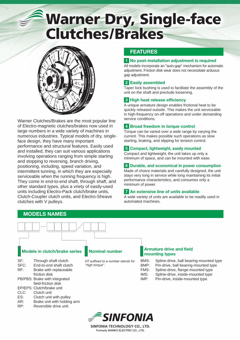
PAN-CAKEDRY, SINGLE-PLATE CLUTCHES/BRAKESOur clutches and brakes
used in various equipment including industrial equipment,
information equipment and recreation facilities play
an important part in automation or
motion control systems in terms of
power transmission and control.
SHINKO ELECTRIC CO., LTD.Please note that our former company name or logo may be printed in this catalog.
Formerly SHINKO ELECTRIC CO., LTD.
Formerly SHINKO ELECTRIC CO., LTD.
Formerly
Shiba NBF Tower, 1-30, Shiba-daimon 1-chome, Minato-ku, Tokyo, 105-8564, JapanTEL +81-3-5473-1826 FAX +81-3-5473-1845
SINFONIA TECHNOLOGY CO., LTD. continually upgrades and improves its products. Actual features and specifications may therefore differ slightly from those described in this catalog.
96 Robinson Road, #13-02 SIF Building, Singapore 068899TEL +65-6223-6122 FAX +65-6225-2729
Graha Paramita 8th Floor Suite E Jl. Denpasar Raya Block D2 KAV. 8 Kuningan, Jakarta 12940, IndonesiaTEL: 021-252-3606 (hunting) FAX: 021-252-3608
Room3006, Building B Far East International Plaza, No 317, Xian Xia Road, Changning District, Shanghai, ChinaZip Code:200051TEL +86-21-6275-0606 FAX +86-21-3209-8975
For safe and reliable operation, it is essential to read the user,s manual carefullybefore using this equipment.
2007 4A SPrinted in Japan
Our clutches and brakes
used in various equipment including industrial equipment,
information equipment and recreation facilities play
an important part in automation or
motion control systems.
We have a new slogan in Japan; “ECOing” a combination of “eco” and “ing” . This is to promote eco-friendly technological development and manufacturing. Our ecological activities are of course not limited to Japan and practiced in many countries around the world.
E71-520CODE http://www.sinfo-t.jp

1 2
Due to their unique structure, our pancake-type electromagnetic clutches/brakes provide such helpful features as easy installation and space-saving design. Of course, they offer superior characteristics and reliability as electromagnetic clutches and brakes, and the uniquely shaped, highly reliable leaf spring ensures operating characteristics of high precision and outstanding response. This series is characterized by major features thin and compact design, high performance and easy to install. The pancake type series clutch/brake system is ideally suited for controlling the motion of various machines.
1. Thin and CompactThis product features a low profile and can be installed in a limited space.
4. Asbestos-Free FacingDue to the use of non-asbestos materiaI and safety facing, this product can be emptoyed in food and packaging machines.
2. No BacklashThe origlnal leaf-spring drive system ensures no backlash in the direction of rotation.
5. Easy Installation and Mountable in Any PositionThe system can be installed in any direction (i.e., vertical, horizontal or diagonal).
6. Superb Response and High precisionThe Ieaf-spring drive system ensures accurate response and is perfect for high-precision controI use.
3. Highly Durable, Clover-Shaped Leaf SpringThe system is equipped with a unique cIover-shaped leaf spring featuring baIanced stress set by the "limited factor method."
Features
Indication of Type
List of Models
NC-0.6-T
Nominal number
TypeNC: ClutchNB: Brake
Attachment typeT: No hub tpyeH: Through shaft typeC: Sprit shsft type
Pancake TypeElectromagneticClutches/Brakes
Pancake typeSeries
TypeClutch
Appearance
Type
Appearance
Brake
NC-TNo hub type
NC-HThrough shaft type
NC-CSprit shaft type
NB-TNo hub type
NB-CHub exterior installetion type

3 4
CIutch or Brake Selection GuideStructureClutch operating modes may be divided into two types: The maximum torque is applied to the system after it has been started fuIIy (for example, in a lathe, on which the work begins to be ground after its rotation has reached the normal speed).The maximum torque is applied when the clutch is actuated (for example, in a conveyor system, in which case the load-is already on the system when the clutch closed).
By referring to Table I or II, it is easy to select the right clutch model for a paticular application from the motor capacity and the clutch shaft speed involved. If you are not sure which type of clutch operating mode is expected, use Table I. If you have a brake in mind, use Table I.
Selection Table I Maximum torque is applied after sysem has fully been started
Selection Table II Maximum torque is applied when sysem is started
Field
Rotor
Coil
Torque arm (for locking)(for whirl-stop)Clover-shaped
leaf spring
Adaptor
hub
Attachment Bolt
Facing (asbestos-free)
Coil
Facing (asbestos-free)
Armature
Clover-shapedleaf spring
Adaptor
Hub
Attachment Bolt
Magnet
Armature
Clutch
Brake
r/minMotor power 100 200 300 400 500 600 700 800 900 1000 1100 1200 1500 1800 2000 2400 3000 3600
kW HP0.015 1/50 0.6 0.3 0.3 0.3 0.3 0.3 0.3 0.3 0.3 0.3 0.3 0.3 0.3 0.3 0.3 0.3 0.3 0.30.035 1/20 1.2 0.6 0.3 0.3 0.3 0.3 0.3 0.3 0.3 0.3 0.3 0.3 0.3 0.3 0.3 0.3 0.3 0.30.065 1/12 2.5 1.2 0.6 0.6 0.3 0.3 0.3 0.3 0.3 0.3 0.3 0.3 0.3 0.3 0.3 0.3 0.3 0.3
0.1 1/8 2.5 1.2 1.2 0.6 0.6 0.6 0.6 0.3 0.3 0.3 0.3 0.3 0.3 0.3 0.3 0.3 0.3 0.30.125 1/5 5 2.5 1.2 1.2 0.6 0.6 0.6 0.6 0.6 0.3 0.3 0.3 0.3 0.3 0.3 0.3 0.6 0.3
0.2 1/4 5 2.5 2.5 1.2 1.2 1.2 1.2 0.6 0.6 0.6 0.6 0.6 0.6 0.3 0.3 0.3 0.3 0.30.25 1/3 10 5 2.5 2.5 1.2 1.2 1.2 1.2 1.2 0.6 0.6 0.6 0.6 0.6 0.3 0.3 0.3 0.30.4 1/2 10 5 5 2.5 2.5 2.5 2.5 1.2 1.2 1.2 1.2 1.2 1.2 0.6 0.6 0.6 0.6 0.30.55 3/4 20 10 5 5 5 2.5 2.5 2.5 2.5 2.5 1.2 1.2 1.2 1.2 1.2 0.6 0.6 0.60.75 1 20 10 10 5 5 5 5 2.5 2.5 2.5 2.5 2.5 1.2 1.2 1.2 1.2 0.6 0.61.1 1 1/2 20 10 10 10 5 5 5 5 5 2.5 2.5 2.5 2.5 2.5 1.2 1.2 1.21.5 2 20 20 10 10 10 10 5 5 5 5 5 2.5 2.5 2.5 2.5 1.2 1.22.2 3 20 20 20 10 10 10 10 10 5 5 5 5 5 2.5 2.5 2.53.7 5 20 20 20 20 10 10 10 10 10 5 5 5 5 2.55.5 7 1/2 20 20 20 20 20 20 10 10 10 10 5 57.5 10 20 20 20 20 20 10 10 10 10 511 15 20 20 20 20 10 1015 20 20 20 20 20 1019 25 20 2022 30 20
r/minMotor power 100 200 300 400 500 600 700 800 900 1000 1100 1200 1500 1800 2000 2400 3000 3600
kW HP0.015 1/50 0.6 0.3 0.3 0.3 0.3 0.3 0.3 0.3 0.3 0.3 0.3 0.3 0.3 0.3 0.3 0.3 0.3 0.30.035 1/20 1.2 0.6 0.6 0.3 0.3 0.3 0.3 0.3 0.3 0.3 0.3 0.3 0.3 0.3 0.3 0.3 0.3 0.30.065 1/12 2.5 1.2 1.2 0.6 0.6 0.6 0.6 0.3 0.3 0.3 0.3 0.3 0.3 0.3 0.3 0.3 0.3 0.3
0.1 1/8 2.5 2.5 1.2 1.2 1.2 0.6 0.6 0.6 0.6 0.6 0.6 0.6 0.3 0.3 0.3 0.3 0.3 0.30.125 1/5 5 2.5 2.5 1.2 1.2 1..2 0.6 0.6 0.6 0.6 0.6 0.6 0.6 0.6 0.3 0.3 0.3 0.3
0.2 1/4 5 5 2.5 2.5 2.5 1.2 1.2 1.2 1.2 1.2 1.2 0.6 0.6 0.6 0.6 0.6 0.6 0.30.25 1/3 10 5 5 2.5 2.5 2.5 1.2 1.2 1.2 1.2 1.2 1.2 1.2 0.6 0.6 0.6 0.6 0.60.4 1/2 10 10 5 5 5 2.5 2.5 2.5 2.5 2.5 2.5 2.5 1.2 1.2 1.2 1.2 0.6 0.60.55 3/4 20 10 10 5 5 5 5 2.5 2.5 2.5 2.5 2.5 2.5 2.5 1.2 1.2 1.2 1.20.75 1 20 20 10 10 10 5 5 5 5 5 5 2.5 2.5 2.5 2.5 2.5 1.2 1.21.1 1 1/2 20 20 10 10 10 10 10 5 5 5 5 5 5 2.5 2.5 2.5 2.51.5 2 20 20 10 10 10 10 10 10 10 5 5 5 5 5 2.5 2.52.2 3 20 20 20 20 10 10 10 10 10 10 10 5 5 5 53.7 5 20 20 20 20 20 20 20 10 10 10 10 55.5 7 1/2 20 20 20 20 10 107.5 10 20 20 20

5 6
CharacteristeicsHeat Dissipation CapacityRelative Speed vs. Torque
Operating Characeristics
Total life/Max speed/Inertia
Discription0.3 0.6 1.2 2.5 5 10 20
NC NB NC NB NC NB NC NB NC NB NC NB NC NB
Armature pull-in time ta (ms)
15 15 20 20 25 25 40 30 50 50 55 50 80 70
Torque build-up time tp (ms)
35 35 45 45 55 55 85 75 110 110 145 120 180 170
Armature release time tar (ms)
20 20 20 20 25 30 40 60 60 60 85 70 110 100
Coil time constant t (ms)
30 25 35 30 55 45 90 50 135 85 170 120 200 160
Note:1. Refer to the above table for calculating the clutch engagement time and braking time.2. The torque rise time includes the armature suction time.3. The above table is based on the rated excitation.
0 1000500 2000 3000 4000 5000 60001
2
3
5
10
20
50
100
200
300
0 1000 2000 3000 4000 5000 6000
100
200
400
300
Relative rotation (r/min) Rrotation (r/min)
Heat
dis
sipa
tion
capa
city
(W)
Torq
ue (N
m)
Type 20
Type 10
Type 5
Type 2.5
Type 1.2
Type 0.6
Type 0.3
Type 20
Type 10
Type 5
Type 2.5
Type 1.2
Type 0.6
Type 0.3
NC-T Non-hub clutch
TypeTotal workload
before adjustment(J)
Max speed of rotation (r/min) Inertia J (kgm2)
when idling when rotating Armature Rotor
NC-0.3 1.50×10⁷ 9500 8000 2.50×10⁻⁵ 4.00×10⁻⁵
NC-0.6-T 4.40×10⁷ 9500 8000 6.20×10⁻⁵ 1.10×10⁻⁴
NC-1.2-T 7.00×10⁷ 7500 6000 1.97×10⁻⁴ 2.75×10⁻⁴
NC-2.5-T 13.0×10⁷ 6000 4500 5.80×10⁻⁴ 8.68×10⁻⁴
NC-5-T 29.0×10⁷ 5000 4000 1.43×10⁻³ 1.98×10⁻³
NC-10-T 52.0×10⁷ 4000 3500
3000
4.75×10⁻³ 6.00×10⁻³
NC-20-T 100×107
Total workloadbefore wear limit
(J)
7.50×10⁷
13.2×10⁷
21.0×10⁷
46.0×10⁷
87.0×10⁷
156×107
300×107 3500 1.60×10⁻² 1.88×10⁻²
NC-H Through shaft clutch
TypeTotal workload
before adjustment(J)
Max speed of rotation (r/min) Inertia J (kgm2)
when idling when rotating Armature Rotor
NC-0.6-H 4.40×10⁷ 9500 8000 1.29×10⁻⁵ 1.10×10⁻⁴
NC-1.2-H 7.00×10⁷ 7500 6000 3.60×10⁻⁴ 2.75×10⁻⁴
NC-2.5-H 13.0×10⁷ 6000 4500 1.11×10⁻⁴ 8.68×10⁻⁴
NC-5-H 29.0×10⁷ 5000 4000 3.03×10⁻³ 1.98×10⁻³
NC-10-H 52.0×10⁷ 4000 3500
3000
9.75×10⁻³ 6.00×10⁻³
NC-20-H 100×107
Total workloadbefore wear limit
(J)
13.2×10⁷
21.0×10⁷
46.0×10⁷
87.0×10⁷
156×107
300×107 3500 3.28×10⁻² 1.88×10⁻²
NC-C Sprit shaft clutch
TypeTotal workload
before adjustment(J)
Max speed of rotation (r/min) Inertia J (kgm2)
when idling when rotating Armature Rotor
NC-0.6-C 4.40×10⁷ 9500 8000 8.98×10⁻⁵ 1.10×10⁻⁴
NC-1.2-C 7.00×10⁷ 7500 6000 2.78×10⁻⁴ 2.75×10⁻⁴
NC-2.5-C 13.0×10⁷ 6000 4500 8.08×10⁻⁴ 8.68×10⁻⁴
NC-5-C 29.0×10⁷ 5000 4000 2.23×10⁻³ 1.98×10⁻³
NC-10-C 52.0×10⁷ 4000 3500
3000
8.75×10⁻³ 6.00×10⁻³
NC-20-C 100×107
Total workloadbefore wear limit
(J)
13.2×10⁷
21.0×10⁷
46.0×10⁷
87.0×10⁷
156×107
300×107 3500 2.43×10⁻² 1.88×10⁻²
NB-C Hub exterior attachment brake
TypeTotal workload
before adjustment(J)
Max speed of rotation (r/min) Inertia J (kgm2)
when idling when rotating Armature
NB-0.6-C 4.40×10⁷ 9500 8000 8.98×10⁻⁵
NB-1.2-C 7.00×10⁷ 7500 6000 2.78×10⁻⁴
NB-2.5-C 13.0×10⁷ 6000 4500 8.08×10⁻⁴
NB-5-C 29.0×10⁷ 5000 4000 2.23×10⁻³
NB-10-C
NB-20-C
52.0×10⁷ 4000 3500
3000
8.75×10⁻³
100×107
Total workloadbefore wear limit
(J)
13.2×10⁷
21.0×10⁷
46.0×10⁷
87.0×10⁷
156×107
300×107 3500 2.43×10⁻²
NB-T Non-hub brake
TypeTotal workload
before adjustment(J)
Max speed of rotation (r/min) Inertia J (kgm2)
when idling when rotating Armature
NB-0.3 1.50×10⁷ 9500 8000 2.50×10⁻⁵
NB-0.6-T 4.40×10⁷ 9500 8000 6.20×10⁻⁵
NB-1.2-T 7.00×10⁷ 7500 6000 1.97×10⁻⁴
NB-2.5-T 13.0×10⁷ 6000 4500 5.80×10⁻⁴
NB-5-T 29.0×10⁷ 5000 4000 1.43×10⁻³
NB-10-T 52.0×10⁷ 4000 3500
3000
4.75×10⁻³
NB-20-T 100×107
Total workloadbefore wear limit
(J)
7.50×10⁷
13.2×10⁷
21.0×10⁷
46.0×10⁷
87.0×10⁷
156×107
300×107 3500 1.60×10⁻²

7 8
Operating Instructions
The friction faces of the Clutch/brake are coated with a rust inhibitive, which need not be wiped off. Mount the components with out further processng, taking care not to contaminate the faces with oil or other foreign matters. They need not be wiped with thinner or trichloroethylene.
2. Do not tighten the field detent. Leave it as loose as a common detent is.
5. For installation accuracy, refer to Table 2.
6. For type NC-T clutches, use two bearings on the armature side (pulley side). The deviation of the armature outside diameter must be within 0.15 T.I.R. and the perpendicularity must be within 0.1 T.I.R. for type 0.3 to 2.5 or within 0.15 T.I.R. for type 5 to 20.
7. For NC-H type clutches, use hexagon socket head cap screws (JIS B1176-1974) to install pulley and sprockets.
- Wire Connection PrecautionsThe supplied electric discharge elements (varistors) are absolutely necessary when the power unit of type DMP is used. When the controller of type TMP, EMP, CSM, or CMPH is used, never install the supplied varistors since electric discharge elements are incorporated.
- Break-inThis series of clutches/brakes are designed to produce the rated torque from the initial stage. However, the specified torque (80% of the rated torque) may not be produced since the frictional faces do not conform sufficiently in the initial installation condition. In this case, perform light break-in operation.
- Installation PostureThe installation posture is free in any direction (vertical, diagonal, etc.) as well as horizontal installation.
3. The mounting screws should be fixed with an adhesive to keep them from loosening.
4. After adjusting the gap (dimension g) between the frictional faces with the attached shim, install the system. Refer to Table 1.
Pre-installation instructions
1. The degree of fitting between the Clutch/brake and the shaft should be H7. h6 or H7. js6 as defined in JIS B0401, and they should be fixed with no play in the axial direction. Where shock loads are expected, the shaft diameter tolerance should be k6 or m6. Also, minimize the end play of the mounting shaft.
Installation instructions
NC
NB
Pulley
Distance collor
Parallel key
Distance collor
Ball bearing
Parallel key
Spring washerHexagon sockethead cap screw
Retaining ring
Retaining ring Retaining ring
Installation Example
Hexagon socket head cap screw
Hexagon socket head cap screw
Table 1 List of Gaps
Table 2 Installation Accuracy
(Note) T.I.R. stands for total dial indicator reading. Accordingly, do not allow misalignment to exceed one-half the values above.
Bearing No.Specified Gap (g)
at InstallationAllowable Maximum
Gap (g) by wear
0.3 0.2+0.1 0.45
0.6 0.2+0.1 0.6
1.2 0.2+0.1 0.6
2.5 0.2+0.1 0.7
5 0.2+0.15 0.9
10 0.3+0.15 1.2
20 0.4+0.2 1.4
Bearing No. Concentricity (T.I.R.)(Shaft and shaft or flange and shaft)
Perpendicularity (T.I.R.)(Flange mounting surface and shaft, and armature mounting surface and shaft)
0.3~2.5 0.1 0.1
5~20 0.15 0.15
0
0
0
0
0
0
0
Unit:mm

9 10
NC-0.3, 0.6-T, 1.2-T, 2.5-T, 5-T, 10-T, 20-T Non-hub Clutch
Model Diameter direction Shuft direction Attachment Shuft holePJA A1 B D1 E G H L M N P Q R g X P.C.D BOLT Z d b t
NC-0.3 58 – 62 29 10 40 35 24 20 1.6 – 4 20 0.2+0.1 5.5 42 M3×6 4.5 10 3 11.5NC-0.6-T 70 58 74 34 14 50 45 29 23 1.6 2 6 23 0.2+0.1 3 46 M3×6 4.5 12 4 13.5NC-1.2-T 88 72 92.5 42 16 62 56 32.5 25.5 2 2 7 25.5 0.2+0.1 4.5 60 M4×8 5.5 15 5 17NC-2.5-T 110 90 116 50 16 71 65 38 29 2 3 9 29 0.2+0.1 5.5 76 M5×10 6.5 20 5 22NC-5-T 137 110 144 64 16 84 78 43.5 33 2.6 3 10.5 33 0.2+0.15 7 95 M6×12 6.5 25 7 28
NC-10-T 172 140 180 80 24 110 100 50.5 37 3.2 4 13.5 37 0.3+0.15 9.5 120 M8×16 8.5 30 7 33NC-20-T 218 180 228 100 24 125 125 60.5 43 3.2 5 17.5 43 0.4+0.2 14 158 M10×22 8.5 40 10 43.5
NC-0.6-H, 1.2-H, 2.5-H, 5-H, 10-H, 20-H Through Shaft Type ClutchModel Static friction torque(Nm) Rated voltage(DC-V) Power consumption at75C(W) Mass(kg)
NC-0.6-T 6 24 8 0.56NC-0.3 3 24 5 0.22
NC-1.2-T 12 24 11 1.0NC-2.5-T 25 24 17 1.8NC-5-T 50 24 25 3.0
NC-10-T 100 24 33 5.6NC-20-T 200 24 42 11.0
Model Static friction torque(Nm) Rated voltage(DC-V) Power consumption at75C(W) Mass(kg)NC-0.6-H 6 24 8 0.72NC-1.2-H 12 24 11 1.3NC-2.5-H 25 24 17 2.3NC-5-H 50 24 25 4.1
NC-10-H 100 24 33 8.0NC-20-H 200 24 42 16
Model Diameter direction Shuft direction Attachment Shuft holePJA A1 B D1 E G H L M N P Q R S Y g P.C.D TAP Z d b t
NC-0.6-H 70 58 74 38 14 50 45 48 23 1.6 20.5 3 23 6 13 0.2+0.1 46 M3 4.5 12 4 13.5NC-1.2-H 88 72 92.5 45 16 62 56 53 25.5 2 22 4.3 25.5 6 14.5 0.2+0.1 60 M4 5.5 15 5 17NC-2.5-H 110 90 116 55 16 71 65 64 29 2 28 6 29 8 18 0.2+0.1 70 M5 6.5 20 5 22NC-5-H 137 110 144 64 16 84 78 80.5 33 2.6 38 7.5 33 12 25 0.2+0.15 80 M8 6.5 25 7 28NC-10-H 172 140 180 75 24 110 100 99.5 37 3.2 52 8.5 37 14 35 0.3+0.15 105 M10 8.5 30 7 33NC-20-H 218 180 228 100 24 135 125 128.5 43 3.2 70 12.5 43 18 50 0.4+0.2 135 M12 8.5 40 10 43.5
B.S600160026004600560066208
0
0
0
0
0
0
0
0
0
0
0
0
0
Note: 1. The exterior ball bearings housed in the through-axis hub should be fixed to the axis with a retaining ring in the axial direction.2. The ball bearings housed in the through-axis employ non-contact seals on both end.3. The adapter is not used for the NC-2.5-H type and later models.
Length of lead wire300 (0.6~2.5type)500(5~20type)
Length of lead wire
Posi
tioni
ng d
iam
eter
Posi
tioni
ng d
iam
eter
300 (0.3~2.5type)500(5~20type)
Ball bearing size (B.S)
Hub attachment tap 3-YJ
Set the clamping depth of theattachment bolt to dimension Sor less.
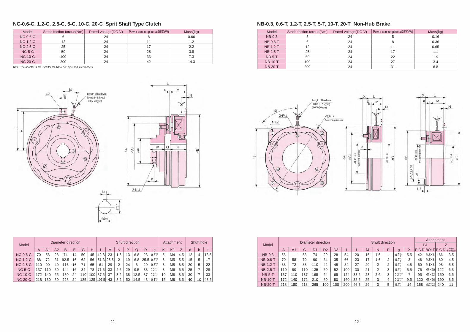
11 12
NB-0.3, 0.6-T, 1.2-T, 2.5-T, 5-T, 10-T, 20-T Non-Hub Brake
ModelDiameter direction Shuft direction
AttachmentPJ Z
A A1 C D1 D2 D3 I L M N P g X P.C.D BOLT P.C.D Holediameter
NB-0.3 58 – 58 74 29 28 54 20 16 1.6 – 0.2+0.1 5.5 42 M3×6 66 3.5NB-0.6-T 70 58 70 90 34 35 66 23 17 1.6 2 0.2+0.1 3 46 M3×6 80 4.5NB-1.2-T 88 72 88 110 42 45 84 27 20 2 2 0.2+0.1 4.5 60 M4×8 98 5.5NB-2.5-T 110 90 110 135 50 52 100 30 21 2 3 0.2+0.1 5.5 76 M5×10 122 6.5NB-5-T 137 110 137 165 64 65 124 33.5 23 2.6 3 0.2+0.15 7 95 M6×12 150 6.5NB-10-T 172 140 172 210 80 80 160 38.5 25 3 4 0.3+0.15 9.5 120 M8×16 190 8.5NB-20-T 218 180 218 265 100 100 200 46.5 29 3 5 0.4+0.2 14 158 M10×22 240 11
NC-0.6-C, 1.2-C, 2.5-C, 5-C, 10-C, 20-C Sprit Shaft Type ClutchModel Static friction torque(Nm) Rated voltage(DC-V) Power consumption at75ϒC(W) Mass(kg)
NB-0.6-T 6 24 8 0.36NB-0.3 3 24 5 0.16
NB-1.2-T 12 24 11 0.65NB-2.5-T 25 24 17 1.1NB-5-T 50 24 22 1.9
NB-10-T 100 24 27 3.4NB-20-T 200 24 31 6.8
Model Static friction torque(Nm) Rated voltage(DC-V) Power consumption at75ϒC(W) Mass(kg)NC-0.6-C 6 24 8 0.66NC-1.2-C 12 24 11 1.2NC-2.5-C 25 24 17 2.2NC-5-C 50 24 25 3.8
NC-10-C 100 24 33 7.3NC-20-C 200 24 42 14.3
ModelDiameter direction Shuft direction Shuft holeAttachment
A A1 A2 B E G H L M N P Q R g K KJ Z d b tNC-0.6-C 70 58 28 74 14 50 45 42.8 23 1.6 13 6.8 23 0.2+0.1 5 M4 4.5 12 4 13.5NC-1.2-C 88 72 31 92.5 16 62 56 51.3 25.5 2 19 6.8 25.5 0.2+0.1 6 M5 5.5 15 5 17NC-2.5-C 110 90 40 116 16 71 65 61 29 2 24 8 29 0.2+0.1 6 M5 6.5 20 5 22NC-5-C 137 110 50 144 16 84 78 71.5 33 2.6 29 9.5 33 0.2+0.15 8 M6 6.5 25 7 28
NC-10-C 172 140 65 180 24 110 100 87.5 37 3.2 38 12.5 37 0.3+0.15 10 M8 8.5 30 7 33NC-20-C 218 180 80 228 24 135 125 107.5 43 3.2 50 14.5 43 0.4+0.2 15 M8 8.5 40 10 43.5
0
0
0
0
0
0
0
0
0
0
0
0
0
Note: The adapter is not used for the NC-2.5-C type and later models.
Length of lead wire300 (0.3~2.5type)500(5~20type)
Length of lead wire
Posi
tioni
ng d
iam
eter
Positioning diameter
Posi
tioni
ng d
iam
eter
300 (0.6~2.5type)500(5~20type)
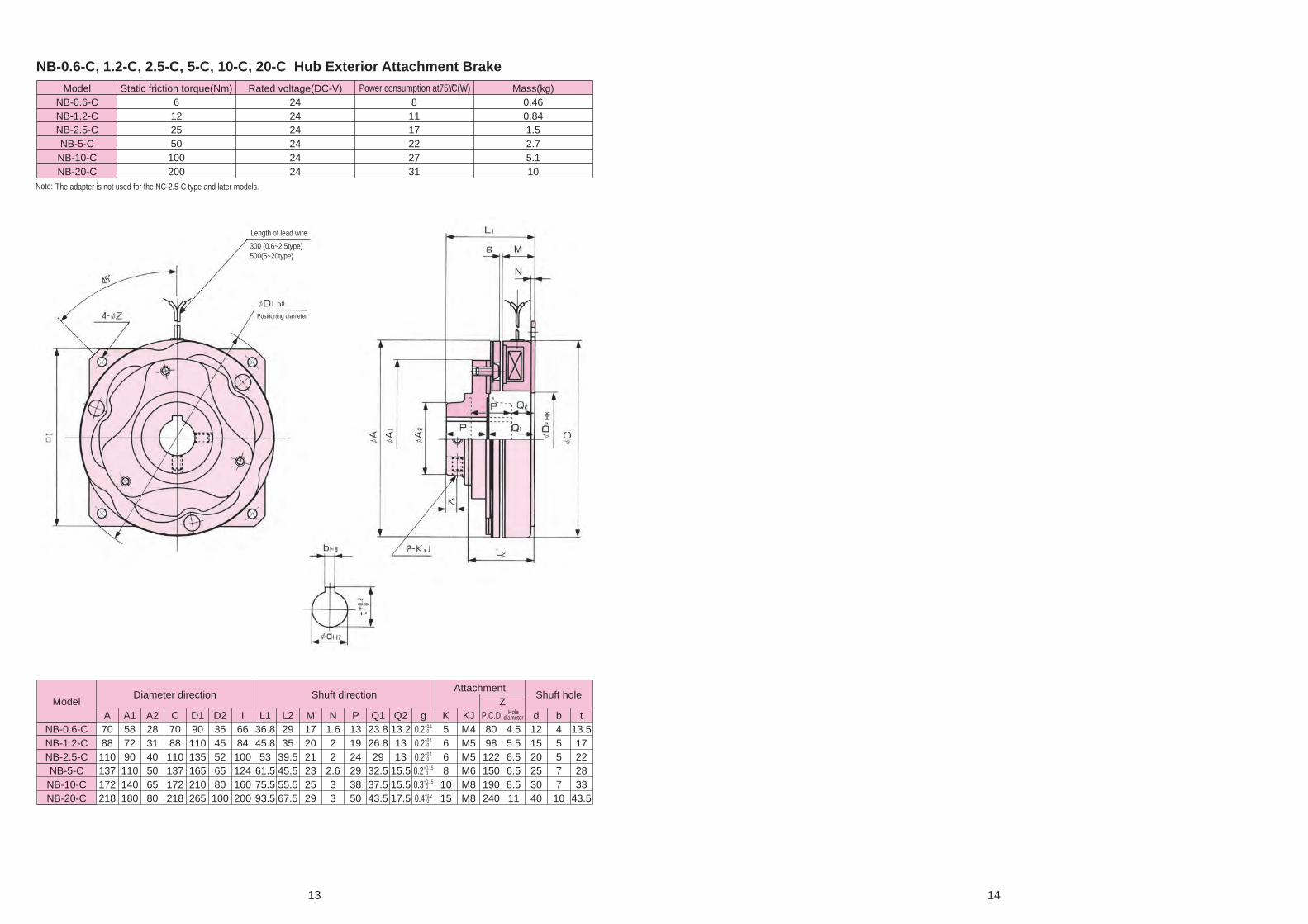
13 14
NB-0.6-C, 1.2-C, 2.5-C, 5-C, 10-C, 20-C Hub Exterior Attachment BrakeModel Static friction torque(Nm) Rated voltage(DC-V) Power consumption at75ϒC(W) Mass(kg)
NB-0.6-C 6 24 8 0.46NB-1.2-C 12 24 11 0.84NB-2.5-C 25 24 17 1.5NB-5-C 50 24 22 2.7NB-10-C 100 24 27 5.1NB-20-C 200 24 31 10
ModelDiameter direction Shuft direction
AttachmentShuft hole
ZA A1 A2 C D1 D2 I L1 L2 M N P Q1 Q2 g K KJ P.C.D d b t
NB-0.6-C 70 58 28 70 90 35 66 36.8 29 17 1.6 13 23.8 13.2 0.2+0.1 5 M4 80 4.5 12 4 13.5NB-1.2-C 88 72 31 88 110 45 84 45.8 35 20 2 19 26.8 13 0.2+0.1 6 M5 98 5.5 15 5 17NB-2.5-C 110 90 40 110 135 52 100 53 39.5 21 2 24 29 13 0.2+0.1 6 M5 122 6.5 20 5 22NB-5-C 137 110 50 137 165 65 124 61.5 45.5 23 2.6 29 32.5 15.5 0.2+0.15 8 M6 150 6.5 25 7 28NB-10-C 172 140 65 172 210 80 160 75.5 55.5 25 3 38 37.5 15.5 0.3+0.15 10 M8 190 8.5 30 7 33NB-20-C 218 180 80 218 265 100 200 93.5 67.5 29 3 50 43.5 17.5 0.4+0.2 15 M8 240 11 40 10 43.5
Holediameter
0
0
0
0
0
0
Note: The adapter is not used for the NC-2.5-C type and later models.
Length of lead wire
Positioning diameter
300 (0.6~2.5type)500(5~20type)

For safe and reliable operation, it is essential to read the user,s manual carefullybefore using this equipment.
2007 4A SPrinted in Japan
Our clutches and brakes
used in various equipment including industrial equipment,
information equipment and recreation facilities play
an important part in automation or
motion control systems.
SHINKO ELECTRIC CO., LTD.Please note that our former company name or logo may be printed in this catalog.
Formerly SHINKO ELECTRIC CO., LTD.
Formerly SHINKO ELECTRIC CO., LTD.
E74-120CODE
Formerly
Shiba NBF Tower, 1-30, Shiba-daimon 1-chome, Minato-ku, Tokyo, 105-8564, JapanTEL +81-3-5473-1826 FAX +81-3-5473-1845
SINFONIA TECHNOLOGY CO., LTD. continually upgrades and improves its products. Actual features and specifications may therefore differ slightly from those described in this catalog.
96 Robinson Road, #13-02 SIF Building, Singapore 068899TEL +65-6223-6122 FAX +65-6225-2729
Graha Paramita 8th Floor Suite E Jl. Denpasar Raya Block D2 KAV. 8 Kuningan, Jakarta 12940, IndonesiaTEL: 021-252-3606 (hunting) FAX: 021-252-3608
Room3006, Building B Far East International Plaza, No 317, Xian Xia Road, Changning District, Shanghai, ChinaZip Code:200051TEL +86-21-6275-0606 FAX +86-21-3209-8975
http://www.sinfo-t.jp
For safe and reliable operation, it is essential to read the user,s manual carefullybefore using this equipment.
2007 4A SPrinted in Japan
Our clutches and brakes
used in various equipment including industrial equipment,
information equipment and recreation facilities play
an important part in automation or
motion control systems.
We have a new slogan in Japan; “ECOing” a combination of “eco” and “ing” . This is to promote eco-friendly technological development and manufacturing. Our ecological activities are of course not limited to Japan and practiced in many countries around the world.

1 2
A claw electromagnetic clutch which transmits torque by a direct linkage of the tooth plane. In addition to the characteristics usually found in a claw electromagnetic clutch (small, high torque and correct transmission), our unique tooth plane and tooth profile delivers incomparable transmission and disengagement characteristics. Additionally, with our unique tooth plane structure, we are able to create a "single position" clutch that mates only at one point on the circumference to enable correct, fixed position engagement and motion.
1. Large torque transmission with a small bodySmall and high torque are both possible due to the claw tooth mating.
4. Can connect even during rotationDepending on the usage condition, it is possible to engage even during (relative) rotation.
2. Torque transmission with no slippageCorrect operation which never slips during torque transmission.
5. Fixed position connection and synchronous operationThis single position clutch does not change its relative position after repeated connections and disconnections, so it is always connected at the proper position.
6. It can be used both wet and dryDepending on the location and the purpose, it is possible to operate this clutch both wet and dry.
3. Zero drag torqueDriving and load are completely separated when the power is cut off with no dragging.
Features
Indication of Type
List of Models
TO-80
Nominal number
Model symbolTZ : Ball bearing attachment type clutchTO : Coil static type clutchTR : Coil rotation type clutchSTZ : Ball bearing attachment type clutchSPO: Coil static single-position type clutch
Tooth Clutches
Tooth SeriesType
Clutch
Appearance
Type
Appearance
Single-position clutch
TZBall bearing attachment type
TOCoil static type
TRCoil rotation type
STZBall bearing attachment type
SPOCoil static single-position type

3 4
Structure
Field
Field
Rotor
Rotor
Coil
Torque arm (for stop rotation)
Spline adapter
Spline adapter
Compression spring
Compression spring
Coil
Armature
Coil
Spline adapter
Compression spring
Armature
Armature
Clutch
Clutch
Clutch
Tooth plane structure of single position type STZ
When engaging Slips without engaging
Tooth plane structure of single position type SPO
When engaging Slips without engaging
* This figure is for TZ type (bearing attachment type). Some are made to order.
*This figure is for TO type (coil static type).
Slip ring
Magnet
Some are made to order.* This figure is for TP type (coil rotation type).

5 6
CharacteristeicsSelection Guide1. Torque reduction rate
2. Operating Characeristics
1. About selection of torque capacityAs the rotation speed increases, the transmission torque lowers by the influences such as vibration of the machine (refer to the torque reduction rate on page 6). Therefore, when selecting torque capacity, reduction is compensated to obtain the required transmission torque based on the rotation speed in use and the torque reduction curve.The torque calculated here is to be the required torque capacity, and the final required torque capacity is determined by treating this with a safety factor (2 or higher).For example, in a case where the required transmission torque is 100Nm, the rotation speed is 300r/min, 60% of the torque is transmitted from the torque reduction rate table, that is, 100Nm x 100/60 = 167Nm. This multiplied by the safety factor 2 equals 334Nm, which is required for the capacity, that is, TO-40 type is required.
2. Engagement limit when relative rotationTooth clutches can be engaged in a state with relative rotation, however, in such a case, the engagement limit of a tooth clutch is restrained by the relative rotation speed, load inertia moment J, and load torque, and will be as shown in Figure 1.If your usage condition is in the area with broken lines in the figure (2 – 80 type and at relative rotation speed of 30r/min or more), please clearly specify your usage condition and consult with us beforehand. Static engagement is basically used for the 280 type and higher. And a single position type (SPO type) may be used for a case exceeding the engagement limit in the above figure, so please contact us.
3. About engagement limit of static engagement useAt the time of static engagement use, there is a case where tooth planes completely engage and a case where tooth planes incompletely engage. In a case of incomplete engagement, the tooth may slip without engagement when the accelerating torque is large on the drive side during start-up. In such a case, the motor must be started by specific methods such as kuza start, star-delta starting, start compensation, and reactor starting to restrain the accelerating torque.
4. Cautions for tooth plane torque of single position typeA single position type slips until it comes to the engagement point owing to its tooth plane structure, and while slipping, slipping generates tooth plane torque and dragging may occur on the load side. In such a case, it is necessary to prevent dragging by using the brake. The size of the tooth plane torque is 15% or less of the rated torque.
5. About restriction of load torque when clutch releaseBecause of the tooth characteristics, the tooth clutch cannot let out if a certain amount of load torque or more acts when releasing. The releasable torque is 20% or less of the rated torque.
1 2 3 5 10 15 30 50 100 3000.000025
0.00025
0.00125
0.0025
0.0125
0.0250.03
0.125
0.25
1.25
2.5
12.5
25
125
250
Type 2
Figure 1
Load
iner
tia m
omen
t J (
kgm
2 )
Relative rotation speed (r/min)
Type 5000
Type 2500
Type 1120
Type 560
Type 280
Type 80
Type 40
Type 20
Type 15
Type 10
Type 5
20
40
60
80
100
0 200 400 600 800 1000 1200 1400 1600
Rotation speed (r/min)
Red
uctio
n ra
te to
rat
ed to
rque
(%
)
TZ/STZ Nominal Number Item 6.3 10 16 25 40 160
Coil time constant t (ms)
25 60 65 95 135 350
Armature pull-in time ta (ms)
70 120 130 140 150 320
Armature release time tar (ms)
30 50 60 70 80 340
TO/SPO Nominal Number Item 2 5 10 15 20 80
Coil time constant t (ms)
10 25 40 50 120 180
Armature pull-in time ta (ms)
50 60 60 100 120 250
Armature release time tar (ms)
40 60 80 100 120
40
150
140
140 250
TR Nominal Number Item 2 5 10 15 20 40 80
Coil time constant t (ms)
20 40 40 70 120 180 200
Armature pull-in time ta (ms)
50 60 60 100 120 140 250
Armature release time tar (ms)
40 60 80 100 120 140 250
Nominal Number Item 280 560 1120 2500 5000
Coil time constant t (ms)
330 340 500 1840 3370
Armature pull-in time ta (ms)
280 300 600 600 1300
Armature release time tar (ms)
300 350 700 2500 2700
3. Maximum rotation speed / Inertia moment J
Type Max speed (r/min)
J (kgm2)
Rotor Armature
TZ/STZ-6.3 5200 5.00×10⁻⁴ 5.00×10⁻⁴
TZ/STZ-10 4500 7.50×10⁻⁴ 7.50×10⁻⁴
TZ/STZ-16 3800 1.25×10⁻³ 1.50×10⁻³
TZ/STZ-25 3300 2.60×10⁻³ 3.25×10⁻³
TZ/STZ-40 2800 5.00×10⁻³ 7.00×10⁻³
TZ/STZ-160 2000 6.30×10⁻² 5.00×10⁻²
Type Max speed (r/min)
J (kgm2)
Rotor Armature
TO/SPO-2 7300 5.00×10⁻⁵ 5.00×10⁻⁵
TO/SPO-5 5200 2.50×10⁻⁴ 5.00×10⁻⁴
TO/SPO-10 4500 5.00×10⁻⁴ 7.50×10⁻⁴
TO/SPO-15 3800 1.00×10⁻³ 1.50×10⁻³
TO/SPO-20 3300 2.25×10⁻³ 3.25×10⁻³
TO/SPO-40 2800 4.75×10⁻³ 7.00×10⁻³
TO/SPO-80 2400 1.10×10⁻² 1.70×10⁻²
Type Max speed (r/min)
J (kgm2)
Magnet body Armature
TR-2 7300 5.00×10⁻⁵ 5.00×10⁻⁵
TR-5 5200 5.00×10⁻⁴ 5.00×10⁻⁴
TR-10 4500 1.00×10⁻³ 7.50×10⁻⁴
TR-15 3800 2.00×10⁻³ 1.50×10⁻³
TR-20 3300 4.75×10⁻³ 3.25×10⁻³
TR-40 2800 1.05×10⁻² 7.00×10⁻³
TR-80 2400 2.45×10⁻² 1.70×10⁻²
TR-280 2000 5.75×10⁻² 4.25×10⁻²
TR-560 1750 1.30×10⁻¹ 8.50×10⁻²
TR-1120 1250 4.45×10⁻¹ 2.85×10⁻¹
TR-2500 1000 3.400 1.250
TR-5000 700 11.65 4.325
TZ/STZ
TR
TO/SPO

7 8
Cautions for handling
(1) Make sure to fix securely in the axial direction in order to keep the attachment clearance g the value specified in the following table in a non-excitation state.
(2) Position the rotor (or the magnet body) and the armature with a collar of nonmagnetic materials (such as brass and stainless steel).
(3) The recommended tolerance of the attachment shaft is H7 · j6 or H7 · k6.
(4) Use a through shaft type of clutch whenever possible. If a split shaft type is to be used, please consult with us beforehand.
(5) Attach the field within the concentricity 0.10 T.I.R to the rotor attachment shaft.
(6) Use bolts to be attached to the field at a length not exceeding the maximum screwing depth of the field.
(7) Apply LOCKTITE, etc., to the attachment bolt of the spline adapter, in order to prevent loosening.
(8) Holes are made beforehand on the spline adapter for pin attachment. Finish them with a reamer to match the actual pin and always use pins together. H7, m6 is recommended for fitting of the pins.
(9) When using a dry type, it is recommended to apply grease thinly to the spline when mounting to smoothen the sliding surfaces of the spline adapter and the armature.
Installation precautions
(1) Purification of lubrication oilPay sufficient attention to purification of the lubrication oil. Attach a magnet plug, etc., on the bottom of the oil bath or the gear box storing the clutch/brake so that fine iron powder such as gear friction powder in the oil does not float. It is necessary to use a suction strainer (about 70~150 mesh) and a magnet plug and a filter together. If contamination of the lubrication oil becomes heavier during operation, or if the amount of sediment becomes larger, filter the oil or replace the oil. Always use the same brand of oil as the currently used oil for replacement.
(2) Temperature control of lubrication oilKeep the oil temperature at 60ϒC or less in a normal operating state. If the temperature increases, thoroughly examine the heat dissipation structure of the gear box or the oil tank, and attach a fan, etc., for forcible air cooling or an oil cooler, etc., to secure a sufficient cooling effect. And in the case of an oil bath, the temperature rise may be excessive owing to oil agitation and loss, etc., so special attention must be paid. If the size of the storing part of the clutch or the brake is small, provide an air vent.
(3) Replacement period of lubrication oil (reference)It is recommended to replace the lubrication oil at the replacement time shown in the table below. Also pay sufficient attention at inspection of the magnet plug and the filter used in order to purify the lubrication oil. Always use the same brand of oil for replacement.
(4) Limit of immersion in lubrication oilImmerse the clutch at 1/2 of its diameter or less in the lubrication oil. Immersing more than 1/2 of the diameter in the oil is unfavorable because of temperature rise.
When using in an oil bath
(10) When using a large type clutch, it is recommended to use a coupling for impact absorption to avoid impact as much as possible.
(11) TZ-160 type and STZ-160 type are for wet operation, therefore use them with the shaft core lubrication method.
Since the power supply part (terminal block, slip ring, brush, etc.) are exposed to exterior, and if hands, fingers, etc., come into contact, an electric shock may occur. Do not directly touch not only during operation but also during maintenance and inspection, and also design so as to install a protective cover, etc.
Design so as to install a cover to the power supply part of the TR type.
Unit: mm
Attachment clearance g
Bearing No. 6.3 10 16 25 40 160
0.3+0.1 0 0.3+0.1
0 0.4+0.1 0 0.4+0.1
0 0.4+0.1 0 0.8+0.3
0
TZ, STZ
Unit: mm
Attachment clearance g
Bearing No. 2 5 10 15 20 40
0.2+0.1 0 0.3+0.2
0 0.2+0.2 0 0.4+0.3
0 0.4+0.3 0 0.4+0.3
0
Attachment clearance g
Bearing No. 80 280 560 1120 2500 5000
0.5+0.3 0 0.8+0.3
0 0.8+0.3 0 0.9+0.3
0 1.5+0.5 0 2.0+0.5
0
TO, TR, SPO
After 4 months or 1000 hours of operation
Number of replacements
1st time
2nd time
3rd time and after
Replacement time
After 1 week or 70 hours of operation
After 1 month or 250 hours of operation
TZ/STZ
TO/SPO
Sprocket
Adapter
Parallel key
Ball bearing
Ball bearing
Parallel key
Hexagon bolt washer spring
Hexagon sockethead cap screw
Retaining ring
Retaining ring
Installation Example
Hexagon socket head cap screw
Hexagon socket head cap screw (to stop rotation)
Hexagon socket head cap screw
Hexagon socket head cap screw
Bearing nut
Bearing washer
Collar
Nonmagnetic collar
Knock pin
Some are made to order.
Ball bearing
Gear
Collar
Nonmagnetic collar Adapter
Knock pin

9 10
TZ-6.3, 10, 16, 25, 40 Ball bearing attachment clutchModel Rated torque(Nm) Rated voltage(DC-V) Power consumption at75ϒC(W) Mass(kg)
TZ-10 100 24 24 2.1TZ-6.3 63 24 24 1.5
TZ-16 160 24 30 3.3TZ-25 250 24 45 4.8TZ-40 400 24 50 8.5
ModelDiameter direction Shaft direction Mounting Shaft hole
A A1 B C D1 D2 E H G L N O P Q R S Y Z g P.C.D AJ DJ d b t
TZ-6.3 76.2 38.1 76.2 76 64 42 16 60 54 66 1.8 2.2 11.2 7.8 47 5.3 2.5 5.5 0.3+0.1 53.75 φ5.5hole, φ9R: 6.5 6 25 7 28
TZ-10 85.9 40 85.9 85.9 73 50 16 64 58 74 1.8 3.15 12.7 7.8 53.5 6.6 3 5.5 0.3+0.1 62.48 φ5.5hole, φ9R: 6.5 6 30 7 33
TZ-16 98.6 45.2 98.6 98 86 58 16 69 63 82 1.8 2.7 15.7 9.3 57 9.4 4 5.5 0.4+0.1 72.90 φ6.5hole, φ11R: 7.5 8 35 10 38.5
TZ-25 117.4 55 117.4 110 103 70 16 74 68 89.1 1.8 4.2 19.0 10.4 59.7 10.4 4 5.5 0.4+0.1 86.87 φ9hole, φ14R: 10 10 40 12 43.5
TZ-40 137.7 64.3 137.7 133 118 84 16 79 73 109.9 1.8 6.2 22.4 12.5 75 13.9 4 5.5 0.4+0.1 101.60 φ9hole, φ14R: 10 10 50 15 55
0
0
0
0
0
Unit: mm
TR
TR
Distance collor
Bearing housing
Coupling shaft
Spring washer
Gear coupling
Bearing nut
Knock pin
Bearing washer
Ball bearing
Nonmagnetic collar
Parallel key
Machine frame AP type brush holder
Some are made to order.
AP type brush holderBrush holder attachment plate
Gear
Ball bearing
Bearing nut
Bearing washer
Nonmagnetic collarKnock pinSome are made to order.
Brush holder for ground
Ball bearing
Parallel key
Hexagon head bolt
Hexagon head bolt
Hexagon head bolt
Hexagon socket head cap screw
Hexagon socket head cap screw

11 12
TZ-160 Ball bearing attachment clutchModel Rated torque(Nm) Rated voltage(DC-V) Power consumption at75ϒC(W) Mass(kg)TZ-160 1600 24 80 18
TO-2, 5, 10, 15, 20, 40, 80 Static coil clutchModel Rated torque(Nm) Rated voltage(DC-V) Power consumption at75ϒC(W) Mass(kg)TO-2 20 24 13 0.60TO-5 50 24 20 1.0
TO-10 100 24 34 1.8TO-15 150 24 34 2.7TO-20 200 24 50 4.2TO-40 400 24 70 7.2TO-80 800 24 79 12
Note: TZ-160 is for wet usage. (Shaft core lubrication)Please contact us for dry usage.
Build-to-order product
ModelDiameter direction Shaft direction
MountingShaft hole
AJ DJ YJ
A A1 B D1 D2 D3 D4 L O P Q R S Y1 Y2 g P.C.D Bolt hole P.C.D Prepared hole for pin P.C.D Tap d b t
TO-2 50.8 15.9 50.8 44 25 46.56 23.04 40.3 2 8.6 6.1 23.6 4.5 2 4.6 0.2+0.1 35 φ3.4hole, φ6.5R: 4 35 4 38.1 M3×4.5 12 4 13.5
TO-5 76.2 38.1 76.2 64 42 71.37 42.82 49.3 2.5 11.2 7.99 27.61 5.3 3 6.1 0.3+0.2 53.75 φ5.5hole, φ9R: 6.5 53.75 6 63.5 M4×5 24 7 27
TO-10 85.9 40 85.9 73 50 79.32 48.39 55.9 2.5 12.7 7.95 32.75 6.6 3 6.6 0.3+0.2 62.48 φ5.5hole, φ9R: 6.5 62.48 6 71.42 M4×5 28 7 31
TO-15 98.6 45.2 98.6 86 58 91.24 55.52 63.0 2.5 15.7 9.75 35.05 9.4 4 6.6 0.4+0.3 72.9 φ6.5hole, φ11R: 7.5 72.9 8 84.12 M5×6 37 10 40.5
TO-20 117.4 55 117.3 103 70 108.7 66.85 71.4 2.5 19 10.78 39.12 10.4 5 9.9 0.4+0.3 86.87 φ8.8hole, φ14R: 10 86.87 10 95.25 M6×6 44 12 47.5
TO-40 137.7 64.3 137.3 118 84 128.5 79.35 86.9 2.5 22.4 12.85 49.15 13.8 6 9.9 0.4+0.3 101.6 φ8.8hole, φ14R: 10 101.6 10 114.3 M6×8 57 15 62
TO-80 162.6 79.3 162.6 144 104 152.3 99.01 104.1 3.8 28.4 14.19 57.71 16.8 8 10.4 0.5+0.3 124.4 φ11hole, φ17.5R: 13 124.4 13 133.3 M8×9 67 18 73
0
0
0
0
0
0
0
Unit: mm
Unit: mm

13 14
TR-2, 5, 10, 15, 20, 40, 80, 280, 560, 1120 Rotation coil clutchModel Rated torque(Nm) Rated voltage(DC-V) Power consumption at75ϒC(W) Mass(kg)TR-2 20 24 13 0.40TR-5 50 24 20 0.90TR-10 100 24 26 1.5TR-15 150 24 34 2.5TR-20 200 24 42 4.1TR-40 400 24 47 6.8TR-80 800 24 47 12
TR-280 2800 24 71 17TR-560 5600 24 78 27
TR-1120 11200 24 93 60
TR-2500, 5000 Rotation coil clutchModel Rated torque(Nm) Rated voltage(DC-V) Power consumption at75ϒC(W) Mass(kg)
TR-2500 25000 24 125 195Tr-5000 50000 100 175 435
Note: TR-1120 is build-to-order product.
Build-to-order product
ModelDiameter direction Shaft direction
MountingShaft hole
AJ DJ
A A1 C D1 D2 L P Q R S T U Y1 g P.C.D Bolt hole P.C.D Prepared hole for pin d b t
TR-2 50.8 15.9 52.3 44 25 37.6 8.6 7.1 21.9 4.5 6.3 3.9 2 0.2+0.1 35 φ3.4hole, φ6.5R: 4 35 4 12 4 13.5
TR-5 76.2 38.1 77.7 64 42 39.9 11.2 7.8 20.9 5.3 6.3 5.1 3 0.3+0.2 53.75 φ5.5hole, φ9R: 6.5 53.75 6 32 10 35.5
TR-10 85.9 44.4 90.5 73 50 45.2 12.7 7.74 24.7 6.6 6.3 5.1 3 0.3+0.2 62.48 φ5.5hole, φ9R: 6.5 62.48 6 37 10 40.5
TR-15 98.6 52.3 104.8 86 58 54.6 15.7 9.56 29.3 9.4 6.3 5.1 4 0.4+0.3 72.9 φ6.5hole, φ11R: 7.5 72.9 8 42 12 45.5
TR-20 117.4 62 122.2 103 70 64.3 19 10.6 34.6 10.4 6.3 5.1 5 0.4+0.3 86.87 φ8.8hole, φ14R: 10 86.87 10 52 15 57
TR-40 137.7 71.4 142.9 118 84 76.2 22.4 12.5 41.2 13.8 8 5.6 6 0.4+0.3 101.6 φ8.8hole, φ14R: 10 101.6 10 62 18 68
TR-80 162.6 85.9 168.3 144 104 90.9 28.4 14.0 48.4 16.8 8 5.6 8 0.5+0.3 124.46 φ11hole, φ17.5R: 13 124.46 13 72 20 78
TR-280 195.1 98.6 200 173 118 104.9 28.4 17.3 59.1 8.6 8 6.2 7 0.8+0.3 146 φ14hole, φ20R: 13.5 146 13 82 24 90
TR-560 223.5 111.3 230 197 140 117.4 28.4 21.5 67.4 8.6 8 6.2 7 0.8+0.3 170 φ14hole, φ20R: 13.5 170 13 97 28 106
TR-1120 282.6 148 304.8 250 172 165.6 45 25.9 94.7 20.4 9.5 17.5 10 0.9+0.3 214 φ18hole, φ26R: 19 214 16 127 35 138
ModelDiameter direction Shaft direction Mounting Shaft hole
A A1 B C C1 D1 D2 L P Q R S g P.C.D AJ DJ d b t
TR-2500 420 210 420 320 230 365 255 319.3 55 34.3 180 25 1.5 315 φ26hole, φ39 φ20–0.1 170 42 183
TR-5000 540 260 540 380 280 460 310 391 70 51 220 30 2 380 φ33hole, φ51 φ30–0.1 200 45 2140
0
0
0
0
0
0
0
0
0
–0.2
–0.4
Unit: mm
Unit: mm

15 16
STZ-6.3, 10, 16, 25, 40 Ball bearing attachment single-position clutchModel Rated torque(Nm) Rated voltage(DC-V) Power consumption at75ϒC(W) Mass(kg)
STZ-10 100 24 24 2.1STZ-6.3 63 24 24 1.5
STZ-16 160 24 30 3.3STZ-25 250 24 45 4.8STZ-40 400 24 50 8.5
STZ-160 Ball bearing attachment single-position clutchModel Rated torque(Nm) Rated voltage(DC-V) Power consumption at75ϒC(W) Mass(kg)
STZ-160 1600 24 80 18Note: STZ-160 is for wet usage. (Shaft core lubrication)
Please contact us for dry usage.
Build-to-order product
ModelDiameter direction Shaft direction Mounting Shaft hole
A A1 B C D1 D2 E H G L N O P Q R S Y Z g P.C.D AJ DJ d b t
STZ-6.3 76.2 38.1 76.2 76 64 42 16 60 54 66 1.8 2.2 11.2 7.8 47 5.3 2.5 5.5 0.3+0.1 53.75 φ5.5hole, φ9R: 6.5 6 25 7 28
STZ-10 85.9 40 85.9 85.9 73 50 16 64 58 74 1.8 3.15 12.7 7.8 53.5 6.6 3 5.5 0.3+0.1 62.48 φ5.5hole, φ9R: 6.5 6 30 7 33
STZ-16 98.6 45.2 98.6 98 86 58 16 69 63 82 1.8 2.7 15.7 9.3 57 9.4 4 5.5 0.4+0.1 72.90 φ6.5hole, φ11R: 7.5 8 35 10 38.5
STZ-25 117.4 55 117.4 110 103 70 16 74 68 89.1 1.8 4.2 19.0 10.4 59.7 10.4 4 5.5 0.4+0.1 86.87 φ9hole, φ14R: 10 10 40 12 43.5
STZ-40 137.7 64.3 137.7 133 118 84 16 79 73 109.9 1.8 6.2 22.4 12.5 75 13.9 4 5.5 0.4+0.1 101.6 φ9hole, φ14R: 10 10 50 15 55
0
0
0
0
0
Unit: mm
Unit: mm

17 18
SPO-2, 5, 10, 15, 20, 40, 80 Static coil single-position clutchModel Rated torque(Nm) Rated voltage(DC-V) Power consumption at75ϒC(W) Mass(kg)SPO-2 20 24 13 0.60SPO-5 50 24 20 1.0SPO-10 100 24 34 1.8SPO-15 150 24 34 2.7SPO-20 200 24 50 4.2SPO-40 400 24 70 7.2SPO-80 800 24 79 12
Brush holder for TR type clutchesThe brush and holder shown below are required to use the rotation coil tooth clutch (TR type). Please order this part separately as it is not included with the clutch.
Tubler brush holder for small class TR type clutchesBrush for AP-223 typeFor wet usage:AP-223-1/For dry usage : AP-223-2
Tubler type brush holder for middle class TR type clutchesBrush for AP-45 typeFor wet usage:AP-45-1/For dry : usageAP-45-2
Multiple brush holder A for large TR typeThis is the brush holder used for the TR-2500 and TR-5000 type.
When AP type brushes are used, please connect the plus side of the brush to the clutch spring and the minus side of the brush to the yoke side.
(Note)
(Note)
(Note)
1. The tubler brush can be used for both wet and dry operation by changing the brush module. Wet operation uses a braided bronze brush and dry operation uses a copper carbon brush.
2. During wet operation, if the peripheral speed of the spring is more than 12.7m/s or if the current usually flows on the spring, attach 2 brushes with a 90-degree angle between them and apply the current across both brushes.
3. Connect the plus side to the brush holder and connect the minus side to the separate brush sliding on the shaft attached to the clutch body Be careful not to connect the plus and minus terminals inversely..
4. When the clutch is used while submersed in oil, attach an idler brush in the forward direction of rotation without applying any additional current.5. If you use a clutch larger than our typeTR-280 for wet operation, use 4 AP45-1 type brushes, designating one as an idler, as is described in note 4.
1. The TO and SPO types are designed to be attached to a fixing adapter or a fixed part of the machine to maintain proper thermal dissipation. If there is insufficient space for ventilation or if the clutch is installed in a sealed box with direct sun exposure, the ambient temperature will increase. Please contact us for application advice.
2. If using the TR-280, 560, or 1120 types, attach the grounding brush to the shaft in order to protect the machine's shaft bearing.
Brush holder type Application Brush type Number of uses Applicable clutch type
AP-223For wet mode AP-223-1 1 TR-2~15
For dry mode AP-223-2 1 TR-2~15
AP-45
For wet mode AP-45-11 TR-20~80
4 TR-280~5000
For dry mode AP-45-21 TR-20~80
2 TR-280~1120
Multiple A type For dry mode 8×10×25 1 set (4 pieces) TR-2500~5000
Brush typeDimension
(mm)
Maximum allowable current
(A)
Maximum allowable peripheral
speed(m/s)
Contact pressure
(N)Memo
AP-223-1 φ4×16 3 12.7 10 With pigtail and spring
AP-223-2 φ4×16 1.4 25 3.5 With pigtail and spring
AP-45-1 φ6×20 6 12.7 20 With pigtail and spring
AP-45-2 φ6×20 3 25 5 With pigtail and spring
Multiple A type 8×10×25 20 25 2~2.5 1 set (4 pieces) with pigtail
Brush holder and its application table
Brush performance specification list
Unit: mm
Unit: mm
Unit: mm
ModelDiameter direction Shaft direction
MountingShaft hole
YJ
A A1 B D1 D2 D3 D4 L O P Q R S Y1 Y2 g P.C.D AJ DJ P.C.D Tap d b t
SPO-2 50.8 15.9 50.8 44 25 46.5 23.0 40.3 2 8.6 6.1 23.6 4.5 2 4.6 0.2+0.1 35 φ3.4hole, φ6.5R: 4 4 38.1 M3×4.5 12 4 13.5
SPO-5 76.2 38.1 76.2 64 42 71.3 42.8 49.3 2.5 11.2 7.99 27.6 5.3 3 6.1 0.3+0.2 53.75 φ5.5hole, φ9R: 6.5 6 63.5 M4×5 24 7 27
SPO-10 85.9 40 85.9 73 50 79.3 48.3 55.9 2.5 12.7 7.95 32.7 6.6 3 6.6 0.3+0.2 62.48 φ5.5hole, φ9R: 6.5 6 71.42 M4×5 28 7 31
SPO-15 98.6 45.2 98.6 86 58 91.2 55.5 63 2.5 15.7 9.75 35.0 9.4 4 6.6 0.4+0.3 72.9 φ6.5hole, φ11R: 7.5 8 84.12 M5×6 37 10 40.5
SPO-20 117.4 55 117.3 103 70 108.71 66.8 71.4 2.5 19 10.78 39.12 10.4 5 9.9 0.4+0.3 86.87 φ8.8hole, φ14R: 10 10 95.25 M6×6 44 12 47.5
SPO-40 137.7 64.3 137.3 118 84 128.55 79.3 86.9 2.5 22.4 12.85 49.15 13.8 6 9.9 0.4+0.3 101.6 φ8.8hole, φ14R: 10 10 114. M6×8 57 15 62
SPO-80 162.6 79.3 162.6 144 104 152.35 99.0 104.1 3.8 28.4 14.19 57.71 16.8 8 10.4 0.5+0.3 124.46 φ11hole, φ17.5R: 13 13 133.35 M8×9 67 18 730
0
0
0
0
0
0
Unit: mm

For safe and reliable operation, it is essential to read the user,s manual carefullybefore using this equipment.
2006 11A SPrinted in Japan
PARTICLECLUTCHES/BRAKESOur clutches and brakes
used in various equipment including industrial equipment,
information equipment and recreation facilities play
an important part in automation or
motion control systems.
SHINKO ELECTRIC CO., LTD.Please note that our former company name or logo may be printed in this catalog.
Formerly SHINKO ELECTRIC CO., LTD.
Formerly SHINKO ELECTRIC CO., LTD.
E75-120CODE
Formerly
Shiba NBF Tower, 1-30, Shiba-daimon 1-chome, Minato-ku, Tokyo, 105-8564, JapanTEL +81-3-5473-1826 FAX +81-3-5473-1845
SINFONIA TECHNOLOGY CO., LTD. continually upgrades and improves its products. Actual features and specifications may therefore differ slightly from those described in this catalog.
96 Robinson Road, #13-02 SIF Building, Singapore 068899TEL +65-6223-6122 FAX +65-6225-2729
Graha Paramita 8th Floor Suite E Jl. Denpasar Raya Block D2 KAV. 8 Kuningan, Jakarta 12940, IndonesiaTEL: 021-252-3606 (hunting) FAX: 021-252-3608
Room3006, Building B Far East International Plaza, No 317, Xian Xia Road, Changning District, Shanghai, ChinaZip Code:200051TEL +86-21-6275-0606 FAX +86-21-3209-8975
http://www.sinfo-t.jp
For safe and reliable operation, it is essential to read the user,s manual carefullybefore using this equipment.
2007 4A SPrinted in Japan
Our clutches and brakes
used in various equipment including industrial equipment,
information equipment and recreation facilities play
an important part in automation or
motion control systems.
We have a new slogan in Japan; “ECOing” a combination of “eco” and “ing” . This is to promote eco-friendly technological development and manufacturing. Our ecological activities are of course not limited to Japan and practiced in many countries around the world.

1 2
We use a special magnetic powder to transmit and control the torque on this series of clutches/brakes. The original powder and advanced structural design create incomparable performance in torque control and slip usage. Our unique materials and manufacturing expertise produce a high quality, nearly spherical powder, which dramatically improves the performance and reliability of our product, truly making this the ideal powder clutch/brake.
1. High precision torque over a wide range of valuesBy using efficient magnetic circuitry, the transmitted torque can be varied between 3% and 100% of maximum rated torque.
2. Stable torque and long operating lifeThe ideal spherical powder obtains stable torque and smooth slip operation.
3. High thermal radiation capabilityUsing a heat resistant powder, and a structure with high thermal radiation capability, our devices are capable of heavy continuous slip operation. slip operation.Heat pipe powder brake is incredible thermal radiation capability which outperforms water-cooled models.
4. Non-shock, smooth linkage and brakeAchieve an excellent buffer effect with its constant torque and smooth slip torque.
5. Non-abrasive powder and silent operationUnlike abrasive clutches/brakes there is no wearing powder, and silent operation is possible since there is no linkage sound.
6. Rapid responseThe generated magnetic flux operates instantaneously as the effective flux, providing rapid torque response.
Features
Models Names
List of Models
Nominal number
Model symbolPOC: Shaft type / Naturally cooled clutchPHC: Hollow center type / Self-ventilating clutchPMC: Micro type / Naturally cooled clutchPOB: Shaft type / Naturally cooled brakePHB: Hollow center type / Naturally cooled brakePRB-H: Hollow center type / Naturally cooled brake (with side fin)PTB: Shaft type / Heat pipe cooled brake
Type
Clutch
Appearance
Type
Appearance
Brake
POCNaturally cooled
POBNaturally cooled
PHBNaturally cooled
PRB-HNaturally cooled (with side fin)
PTBHeat pipe cooled
PHC-RSelf-ventilating
PMCNaturally cooled
Particle Clutches/Brakes
Particle typeSeries
POB-10
Shaft type Hollow center type
Shaft type Shaft typeHollow center type Hollow center type
Micro type

3 4
DESIGN AND OPEFIATIONThe main components of the clutch/brake are the electromagnetic field (stationary part) containing the coil, the drive-part of the clutch (cylinder and input shaft) and the driven-part of the clutch (rotor and output shaft). The cylindrical space between the cylinder and the rotor is filled with dry magnetic particle. The cylinder is the nonsaturation type incorporating a nonmagnetic-flux barrier ring in the center of its rim. Consequently, its built-up characteristics is excellent.When the coil is excited with direct current from electrical source, the magnetic flux, as illustrated in the figure below, is established. The magnetized particle contained between the two rotating parts (rotor and cylinder) are solidified into a chainlike configuration, which bind tightly the two rotating
parts together. When the coil is deenergized, the magnetic flux instantaneously disappears, the solidified particles disperse, and the transmission of torque ceases immediately.Due to its structural design where the input and output shafts are of the split-shaft type or simple hollowed shaft type, installation of clutches and brakes is simplified. Moreover, since the stationary coil type, no sliping and brush are required. This facilitates inspection and maintenance of the equipment. In the case of the electromagnetic particle brake, the operating principle is identical with that of the clutch. However, the rotor, illustrated in the figure, is fixed to the bracket. When the coil is excited, braking is initiated.
Principle of heat pipe:The heat pipe has for the first time been utilized by NASA to cope with incandescence or space ships and heat dissIpation of communication devices, a new technology by which a large quantity of heat can be transported rapidly. Its distinguished features are wide spreading over various fields including electrical equipment field.
Structure
POC
POB
Stationary part of the clutch
Seal
Drive-part of the clutch(rotor and output shaft)
Magnetic-flux path
Field coil
Input shaftOutput Shaft
Dry magnetic particles
Drive-part of the clutch(cylinder and input shaft)
Electrical power input (D.C.)
Heat outputHeat input
Steam striam
Container Wick
Back flow of opration liquidabiabatic section
Heat reception section Heat dissipation section
Coil
Output shaft
Rotor
Yoke
Cylinder
Input shaft
Powder
Bracket
Yoke
Coil
Cylinder
Fixed rotor
Fixed bracket
Powder
Input shaft
Input side bracket
Nonmagnetic-flux barrier ring

5 6
PMC
PRB-H
PHC-R
PHB
Yoke Fan
CoilInput side bracket
Cylinder
Rotor
Output hub
Input hub
Powder
Output side bracket
CylinderYoke
Coil
Input side bracket
Fixed rotor
Fixed bracket
PowderHub
Yoke
Coil
Output shaft
Cylinder
Rotor
PowderInput hub
Side plate A
Yoke
Coil
Rotor
Powder
Side plate B

7 8
1. To use in the state of continuous slipTo use in the state of continuous slip with a constant torque and a constant rpm for tension control of dummy loads and start up windlng brake, the continuous slip power is calculated by the following formula. Here, it is possible to use the required brake torque by adjustirlg the rated torque in the range 3~100%.
Ps=0.103xTxn (W) T: Set torque of brake (Nm) n: rpm of brake shah (r/min)
Example (Conditions) Set torque of brake: T=35 (Nm) rpm of brake:n=65(r/min) Select the brake for the above state.
(1) Temporarily select the one having the rated torqur 50 Nm from the set torque 35Nm.
(2) Calculate the slip power. Ps=0.103×35×65≠234WThe type having the slip power larger than 234W is required.
(3) The type may be selected from the allowable slip power diagram:For the shaft type, the allowable slip power of POB-10 is 270W (234W<270W). Therefore, POB-10 may be used.
(4) The simple selection table below with the continuous slip power considered is based on rpm of 1000 r/min. Therefore, it is required to determine the feasibility of use at this rpm by an allowable slip power diagram.
2. To make tension controlTo make constant tension control with continuous slip applying a start up winding brake, calculation is made using the following formulae:
Principal data dimensions of application conditions necessary for exarmination: 1. Line speed: Maximum Vmax. Minimum Vmin (m/min) 2. Start up wlndlng dia: Maximum Dmax. Minimum Dmin (mm ø) 3. Set tension: Maximum Fmax, Minimum Fmin (N)
1) For start up winding brakeTo make start up winding control applying the electromagnet powder brake, following points should be examined:
1) For start up winding brakeTo make start up winding control applying the electromagnet powder clutch, following points should be examined:
(Example)[Conditions]1.Line speed: Maximum Vmax=160m/min Minimum Vmin=85m/min2.Start up winding dia.: Maximum Dmax=ø900mm Minimum Dmin=ø150mm3.Settension: F=140(N)constantSelect the brake for the above state.
(Example)[Conditions]1.Line speed: Maximum Vmax=30m/min Maximum Dmax=ø650mm Minimum Dmin=ø150mm3.Settension: F=120(N)constantSelect the clutch for the above state.
Slip power of 367W or more and torque of 63Nm or more may be required.
(8) The allowable slip power of POB-20 is 430W (367W<430W, 63 Nm<200 Nm) according to the Allowable Slip Power Diagram (see page 234), so POB-20 is available.
(2) Required brake torque (T) at final stage and rpm of brake (N)
(3) Maximum rpm (Nmax)
T= ×10–3(Nm)Fmax×Dmax2
N= ×103(r/min)Vmaxπ×Dmax
Nmax= ×103(r/min)Vmaxπ×Dmin
(4) Minimum rpm (Nmin)
Nmin= ×103(r/min)Vminπ×Dmin
(5) Minimum brake torque (Tmin)
T= ×10–3(Nm)Fmin×Dmin2
Tmin= ×10–3(Nm)Fmin×Dmin2
(6) Maximum brake torque (Tmax)
Tmax= ×10–3(Nm)Fmax×Dmax2
(7) Maximum slip power (Pmax)
Pmax= 0.0164×Fmax×Vmax (W)
N= ×103(r/min)Vminπ×Dmin
(1) Required brake torque (T) at start up and rpm of brake (N)
(2) Required brake torque (T) at final stage and rpm of brake (N)
(3) Maximum rpm (Nmax)
T= ×10–3=63(Nm)140×9002
N= ×103=56.6(r/min)160π×900
T= ×10–3=9(Nm)120×1502
Ns= ×103=64(r/min)30π×150
Nmax= ×103=339.5(r/min)160π×150
(4) Minimum rpm (Nmin)
Nmin= ×103=30.1(r/min)85π×900
(5) Minimum brake torque (Tmin)
T= ×10–3=10.5(Nm)140×1502
Tmin= ×10–3=10.5(Nm)140×1502
(6) Maximum brake torque (Tmax)
Tmax= ×10–3=63(Nm)140×9002
(7) Maximum slip power (Pmax)
Pmax= 0.0164×140×160=367 (W)
N= ×103=339.5(r/min)160π×150
(1) Required brake torque (T) at start up and rpm of brake (N)
Simple Selection Table with Slip Power Considered(1000 r/min)
(2) Required clutch torque (T) at final stage and rpm of output shaft (Ns)
(3) Maximum rpm (Nmax)
T= ×10–3(Nm)Fmax×Dmin2
Ns= ×103(r/min)Vmaxπ×Dmin
Nmax= ×103(r/min)Vmaxπ×Dmin
(4) Minimum rpm (Nmin)
Nmin= ×103(r/min)Vminπ×Dmin
(5) Minimum clutch torque (Tmin)
T= ×10–3(Nm)Fmax×Dmax2
Tmin= ×10–3(Nm)Fmin×Dmin2
(6) Maximum clutch torque (Tmax)
Tmax= ×10–3(Nm)Fmax×Dmax2
(7) Maximum slip power (Pmax)
Ns= ×103(r/min)Vmaxπ×Dmax
(1) Required clutch torque (T) at start up and rpm of output shaft (Ns)
(1) Required clutch torque (T) at start up and rpm of output shaft (Ns)
N0
NmaxDmaxDminPmax= 0.0164×Fmax×Vmax× × –1( ) (W)
N0 : rpm of clutch input shaft
Cooling System
Rated Torque
(Nm)
Model
Allowable Slip Power (W)
Natural Cooling System
Natural Cooling System
190080045029018013084
190080045029018013084
4002001005025126
POC
POB
CIutch or Brake Selection Guide
Controller
Detector
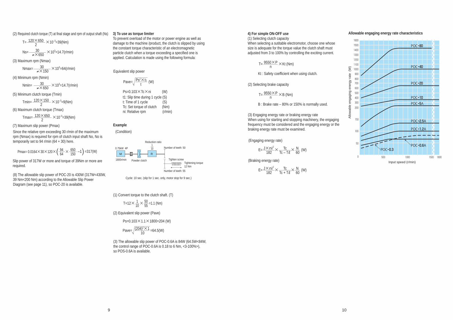
9 10
(2) Required clutch torque (T) at final stage and rpm of output shaft (Ns)
(3) Maximum rpm (Nmax)
Nmax= ×103=64(r/min)30≠×150
(4) Minimum rpm (Nmin)
Nmin= ×103=14.7(r/min)30≠×650
(5) Minimum clutch torque (Tmin)
T= ×10–3=39(Nm)120×6502
Tmin= ×10–3=9(Nm)120×1502
(6) Maximum clutch torque (Tmax)
Tmax= ×10–3=39(Nm)120×6502
(7) Maximum slip power (Pmax)
Ns= ×103=14.7(r/min)30≠×650
9464
650150Pmax= 0.0164×30×120× × –1( ) =317(W)
Since the relative rpm exceeding 30 r/min of the maximum rpm (Nmax) is required for rpm of clutch input shaft No, No is temporarily set to 94 r/min (64 + 30) here.
Slip power of 317W or more and torque of 39Nm or more are required.
(8) The allowable slip power of POC-20 is 430W (317W<430W, 39 Nm<200 Nm) according to the Allowable Slip Power Diagram (see page 11), so POC-20 is available.
3) To use as torque limiterTo prevent overload of the motor or power engine as well as damage to the machine /product, the clutch is slipped by using the constant torque characteristic of an electromagnetic particle clutch when a torque exceeding a specified one is applied. Calculation is made using the following formula:
4) For simple ON-OFF use(1) Selecting clutch capacityWhen selecting a sutitable electromotor, choose one whose size is adequate for the torque value the clutch shaft must adjusted from 3 to 100% by controlling the exciting current.
Equivalent slip power
Pave= Ps2×t1t
(W)
Pave= (204)2×110
=64.5(W)
Ps=0.103×Tc×ni (W)
Ps=0.103×1.1×1800=204 (W)
(3) The allowable slip power of POC-0.6A is 84W (64.5W<84W, the control range of POC-0.6A is 0.18 to 6 Nm, <3-100%>), so POS-0.6A is available.
(2) Equivalent slip power (Pave)
(1) Convert torque to the clutch shaft. (T)
t1: Slip time during 1 cycle (S)t: Time of 1 cycle (S)Tc: Set torque of clutch (Nm)ni: Relative rpm (r/min)
T=12× 110
5055× =1.1 (Nm)
(2) Selecting brake capacity
(3) Engaging energy rate or braking energy rateWhen using for starting and stopping machinery, the engaging frequency must be considered and the engaging energy or the braking energy rate must be examined.
(Braking energy rate)
(Engaging energy rate)
T= ×Kt (Nm)9550×Pn
Kt : Safety coefficient when using clutch.
T= ×B (Nm)9550×Pn
B : Brake rate – 80% or 150% is normally used.
E= (W)J×ni2182
TcTc – TR
× N60
×
E= (W)J×ni2182
TcTc + TR
× N60
×
Allowable engaging energy rate characteristics
M R
Example
(Condition)
Powder clutch
Reduction ratio
Number of teeth: 50
Tighten screw
Number of teeth: 55
Tightening torque12 Nm
Cycle: 10 sec. (slip for 1 sec. only, motor stop for 9 sec.)
0.75kW 4P
1800r/min
110
0
50
100
150
200
300
400
500
600
700800
900
1000
1100
1200
1300
1400
1500
1600
500 1000 1500 1800
POC_0.6APOC_0.3
POC_1.2A
POC_2.5A
POC_5APOC_10
POC_20
POC_40
POC_80
Allo
wab
le e
ngag
ing
ener
gy r
ate
(W
)
Input speed (r/min)
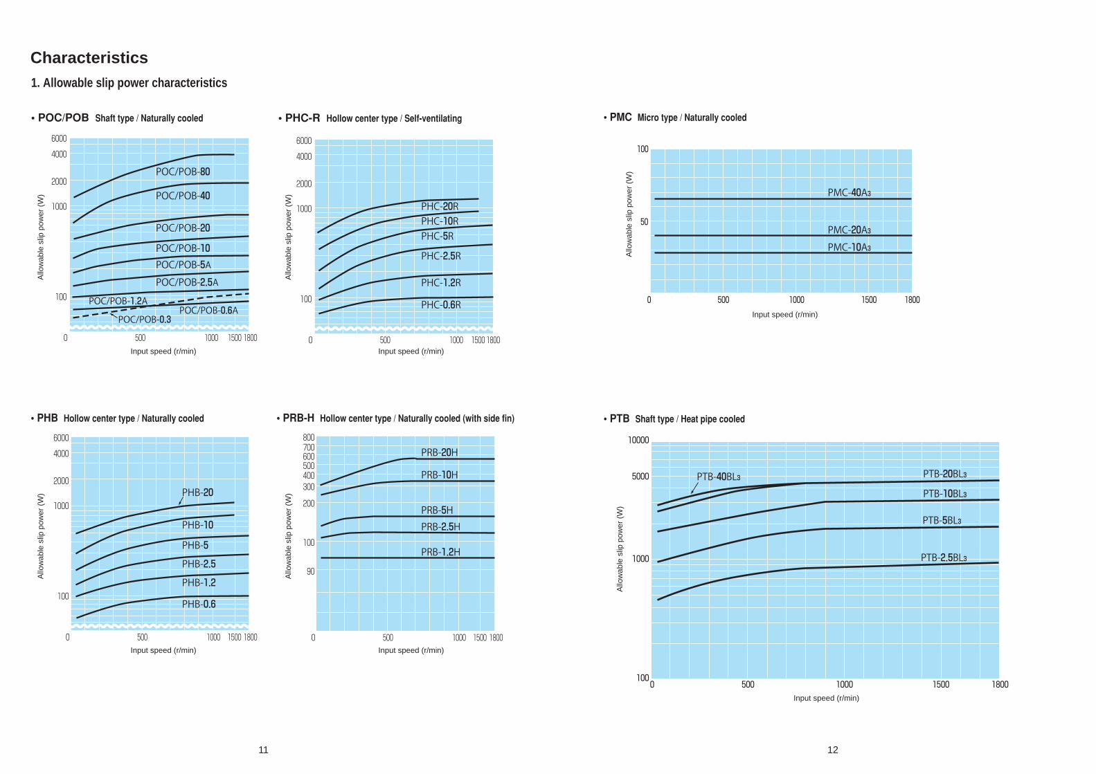
1. Allowable slip power characteristics
Characteristics
• POC/POB Shaft type / Naturally cooled • PHC-R Hollow center type / Self-ventilating
• PHB Hollow center type / Naturally cooled • PRB-H Hollow center type / Naturally cooled (with side fin) • PTB Shaft type / Heat pipe cooled
• PMC Micro type / Naturally cooled
11 12
0
100
1000
2000
4000
6000
500 1000 18001500
POC/POB-80
PHC-20RPHC-10RPHC-5R
PHC-2.5R
PHC-1.2R
PHB-20
PHB-10
PHB-5
PHB-2.5
PHB-1.2
PHB-0.6
PHC-0.6R
PRB-20H
PRB-10H
PRB-5HPRB-2.5H
PRB-1.2H
POC/POB-40
POC/POB-20
POC/POB-10POC/POB-5APOC/POB-2.5A
POC/POB-1.2APOC/POB-0.6A
POC/POB-0.3
0
100
1000
2000
4000
6000
500 1000 18001500 0
90
100
200
300400500600700800
500 1000 18001500
0
100
1000
2000
4000
6000
500 1000 18001500
PMC-40A3
PMC-20A3PMC-10A3
0 500 1000 1500 1800
100
50
0 500 1000 1500 1800100
1000
5000
10000
PTB-40BL3 PTB-20BL3
PTB-10BL3
PTB-5BL3
PTB-2.5BL3
Allo
wab
le s
lip p
ower
(W
)
Input speed (r/min)
Allo
wab
le s
lip p
ower
(W
)
Input speed (r/min)
Allo
wab
le s
lip p
ower
(W
)
Input speed (r/min)
Allo
wab
le s
lip p
ower
(W
)
Input speed (r/min)
Allo
wab
le s
lip p
ower
(W
)
Input speed (r/min)
Allo
wab
le s
lip p
ower
(W
)
Input speed (r/min)

2. Allowable slip torque characteristics
• POC/POB Shaft type / Naturally cooled • PHC-R Hollow center type / Self-ventilating
• PHB Hollow center type / Naturally cooled
• PRB-H Hollow center type / Naturally cooled (with side fin)
• PTB Shaft type / Heat pipe cooled• PMC Micro type / Naturally cooled
13 14
10 100 1000 2000
6
10
100
200
400
PTB- 40BL 3
PTB- 20BL 3
PTB- 10BL 3
PTB- 5BL 3
PTB- 2.5BL 3
POC/POB-80
POC/ POB-40
POC/ POB-10POC/ POB-5
POC/ POB-2.5
POC/POB-1.2
POC/POB-0.6
POC/POB-0.3
POC/ POB-20
1000 2000100101
2
4
6810
20
40
6080100
200
400
6008001000
100010010
10.80.60.4
0.2
2
46810
20
406080100
200
4006008001000
PHB- 0.6
PHB- 1.2
PHB- 2.5
PHB- 5
PHB- 10
PHB- 20
30 100 200 400 1000 2000
1
10
0.1
4PMC- 40A 3
PMC- 20A 3
PMC- 10A 3
1000 200010010
10.80.6
0.4
0.2
2
4
68
10
20
40
6080
100
200
PRB- 2.5H
PRB- 5H
PRB- 10HPRB- 20H
PRB- 1.2H
100010010
10.80.60.4
0.2
2
468
10
20
406080
100
200
400600800
1000
PHC- 10R
PHC- 5R
PHC- 2.5R
PHC- 1.2R
PHC- 0.6R
PHC- 20R
Allo
wab
le s
lip to
rque
(N
m)
Relative rpm (r/min)
Allo
wab
le s
lip to
rque
(N
m)
Relative rpm (r/min)
Allo
wab
le s
lip to
rque
(N
m)
Relative rpm (r/min)
Allo
wab
le s
lip to
rque
(N
m)
Relative rpm (r/min)
Allo
wab
le s
lip to
rque
(N
m)
Relative rpm (r/min)
Allo
wab
le s
lip to
rque
(N
m)
Relative rpm (r/min)

As the cause of drag torque, the effect of clutch bearing loss, seal part friction loss, windage loss, or residual magnetism is suspected. Drag torque has no effect during continuous slip operation, but large drag torque exerts an adverse effect such as load drag during ON/OFF application. SINFONIA TECHNOLOGY CO., LTD. reduces drag torque to approximately 1% of the rated torque in consideration of the above.(Since the value of drag torque varies depending on the model, contact us separately.)
Exciting current – Torque characteristic
Relative rpm – Torque characteristic
Type: POC-0.6ASpeed: 1000r/minRated voltage: DC-24VRated current: 0.792A
Type: POC-5ARated voltage: DC-24VRated current: 1.875A
Drag torque characteristic
15 16
0
2
4
6
8
10
12
14
0 0.2 0.4 0.6 0.8 1.0
0
20
40
60
80
100
0 500 1000 1500 2000
25%
50%
75%
100%
125%
Exciting current
Exciting current (A)
Relative rpm (r/min)
Tor
que
(Nm
)
Tor
que
(Nm
)
0.6321
0.8TR 0.632Tmax
Time
Time
Exciting current
Drag torque
0.368Tmax0.1TR
Saturation torque Tmax
Saturation torque constant
Coil constant
80% torque start time
Torque exit time

• POC-0.3 • POC-0.6A • POC-1.2A
• POC-2.5A • POC-5A • POC-10
• POC-20 • POC-40 • POC-80
• POB-0.3 • POB-0.6A • POB-1.2A
• POB-2.5A • POB-5A • POB-10
• POB-20 • POB-40 • POB-80
Current – Torque characteristics
17 18
0 0.5 1.0
5
10
15
Torque (Nm)
Current(A) 0 0.3 0.6 0.9 1.2
3
4
5
2
1
Torque (Nm)
Current(A)
0 2.0 2.51.51.00.5 3.53.0 4.0
100
200
300
Torque (Nm)
Current(A) 0 1 2 3 4 5 6
5
10
15
Torque (Nm)
Current(A)
0 2 4 6
200
400
600
800
1000
1200
1400
Torque (Nm)
Current(A)
0 0.5 1.0
5
10
15
20
Torque (Nm)
Current(A)
0.8
0 1.0 2.0
10
20
30
40
50
60
70
80
Torque (Nm)
Current(A) 0 0.5 1.0 1.5 2.0 2.5 3.0
50
100
150
Torque (Nm)
Current(A)
1.970 1.0 2.0
10
20
30
Torque (Nm)
Current(A)
1.12
0.55
0 0.5 1.0
5
10
15
0.8
0 1.0 2.0
10
20
30
1.12
0 1.0 2.0
10
20
30
40
50
60
70
80
1.97
0.85
2.20
4.583.832.75
Torque (Nm)
Current(A) 0 0.3 0.6 0.9 1.2
3
4
5
2
1
Torque (Nm)
Current(A)
0 2.0 2.51.51.00.5 3.53.0 4.0
100
200
300
Torque (Nm)
Current(A) 0 1 2 3 4 5 6
5
10
15
Torque (Nm)
Current(A)
0 2 4 6
200
400
600
800
1000
1200
1400
Torque (Nm)
Current(A)
0 0.5 1.0
5
10
15
20
Torque (Nm)
Current(A)
Torque (Nm)
Current(A) 0 0.5 1.0 1.5 2.0 2.5 3.0
50
100
150
Torque (Nm)
Current(A)
Torque (Nm)
Current(A)
0.55 0.85
2.20
4.583.832.75

• PMC-10A3 • MC-20A3
• POB-1.2A
• PMC-40A3
• PRB-1.2H • PRB-2.5H
• PRB-10H • PRB-20H
• PRB-5H
19 20
0 0.1 0.2 0.3 0.4 0.5 0.6
0.5
1
1.5
Torque (Nm)
Current(A)
0.56
0 0.1 0.2 0.3 0.4 0.5 0.6 0.7
1
2
3
Torque (Nm)
Current(A)
0.62
0 0.1 0.2 0.3 0.4 0.5 0.6 0.7 0.8
1
2
3
4
5
Torque (Nm)
Current(A)
0.75
0 0.5 1.0
10
20
40
30
Torque (Nm)
Current(A) 0 0.5 1.0
10
20
40
30
Torque (Nm)
Current(A) 0 0.5 1.0 1.5
25
50
100
75
Torque (Nm)
Current(A)
0.63
1.33 1.58
0.77 1.02
0 0.5 1.0 1.5
50
100
200
250
150
Torque (Nm)
Current(A)
0 0.5 1.0 1.5 2.0
50
100
200
250
150
Torque (Nm)
Current(A)

TYPE Max speed(r/min)
J(kg ㎡)Input side Output side
POC-0.3 1800 5.40×10⁻⁴ 2.01×10⁻⁴
POC-0.6A 1800 7.30×10⁻⁴ 2.40×10⁻⁴
POC-1.2A 1800 1.28×10⁻³ 4.40×10⁻⁴
POC-2.5A 1800 4.10×10⁻³ 1.63×10⁻³
POC-5A 1800 1.05×10⁻² 4.80×10⁻³
POC-10 1800 4.40×10⁻² 1.84×10⁻²
POC-20 1800 9.40×10⁻² 5.00×10⁻²
POC-40 1800 2.50×10⁻¹ 1.30×10⁻¹
POC-80 1500 9.90×10⁻¹ 6.40×10⁻¹
TYPE Max speed(r/min)
J(kg ㎡)Input side
POB-0.3 1800 0.54×10⁻³
POB-0.6A 1800 7.30×10⁻⁴
POB-1.2A 1800 1.28×10⁻³
POB-2.5A 1800 4.10×10⁻³
POB-5A 1800 1.05×10⁻²
POB-10 1800 4.40×10⁻²
POB-20 1800 9.40×10⁻²
POB-40 1800 2.50×10⁻¹
POB-80 1500 9.90×10⁻¹
TYPE Max speed(r/min)
J(kg ㎡)Input side Output side
PHC-0.6R 1800 9.40×10⁻⁴ 3.00×10⁻⁴
PHC-1.2R 1800 1.65×10⁻³ 7.20×10⁻⁴
PHC-2.5R 1800 5.30×10⁻³ 2.08×10⁻³
PHC-5R 1800 1.36×10⁻² 5.80×10⁻³
PHC-10R 1500 6.00×10⁻² 2.60×10⁻²
PHC-20R 1500 1.27×10⁻² 5.50×10⁻²
TYPE Max speed(r/min)
J(kg ㎡)Input side
PHB-0.6 1800 7.50×10⁻⁴
PHB-1.2 1800 1.33×10⁻³
PHB-2.5 1800 4.50×10⁻³
PHB-5 1800 1.07×10⁻²
PHB-10 1800 3.70×10⁻²
PHB-20 1800 9.40×10⁻²
TYPE Max speed(r/min)
J(kg ㎡)Input side Output side
PMC-10A3 1800 0.700 8.50×10⁻²
PMC-20A3 1800 1.210 2.20×10⁻¹
PMC-40A3 1800 3.350 1.090
TYPE Max speed(r/min) J(kg ㎡)
PRB-1.2H 1800 1.10×10⁻³
PRB-2.5H 1800 1.70×10⁻³
PRB-5H 1800 4.78×10⁻²
PRB-10H 1800 1.59×10⁻²
PRB-20H 1800 4.70×10⁻²
TYPE Max speed(r/min) J(kg ㎡)
PTB-2.5BL3 1800 4.10×10⁻³
PTB-5BL3 1800 1.05×10⁻²
PTB-10BL3 1800 4.40×10⁻²
PTB-20BL3 1800 9.40×10⁻²
PTB-40BL3 1800 2.50×10⁻¹
Maximum rpm moment of enertia
• PTB-2.5BL3 • PTB-5BL3
• PTB-10BL3
• PTB-40BL3
• PTB-20BL3
• POC Shaft type / Naturally cooled • POB Shaft type / Naturally cooled
• PHC-R Hollow center type / Self-ventilating • PHB Hollow center type / Naturally cooled
• PRB-H Hollow center type / Naturally cooled (with side fin)
• PTB Shaft type / Heat pipe cooled
• PMC Micro type / Naturally cooled
21 22
0 1.0 2.0
10
20
30
Torque (Nm)
Current(A)
1.25
0 0.5 1.0 1.5 2.0 2.5 3.0
50
100
150
Torque (Nm)
Current(A)
2.2
0 0.5 1.0 1.5 2.0 2.5 3.0 3.5
100
200
300
Torque (Nm)
Current(A)
2.75
0 1.0 2.0
10
20
30
40
50
60
70
80
Torque (Nm)
Current(A)
2.25
0 1.0 2.0 3.0 4.0 5.0 6.0
200
400
600
Torque (Nm)
Current(A)
3.83

Before use(1) Be careful not to the lead wire damage, and be careful of the terminal block, as it is made of resin.
(2) The powder inserted sometimes settles in irregular distributed in the bottom of the unit places, by causing the shock of the transporting, making rotation difficult. In the cases, the unit may be turned upside down and the outside tapped slightly to correct it.
(3) Do not leave the unit in very humid places for a long time.
(4) Take care not to dmage the terminal stand and the electric blower.
At the time of installation(1) During installation, do not apply excessive force to the shaft especially.
(2) When the shaft type is directly connected with mating shaft, use flexible coupling surely. The concentricity and perpendicularity must be with the tolerance of the coupling used.
(3) When connecting the lead wire to the terminal block, use Amp terminal lug surely and fasten securely, and do not expose changed portions. Be careful not to let the lead wire come into contact with the rotating part.
(4) Be careful not to interfere with the ventilation window with the installing stand.
(5) For installation stand over size 5, install on both sides of the input and output. (Refer to the following for installation procedure)
(6) Provide space around the electric blower so as not to
block cooling air.
(7) When the electric blower stops or the ventilation of the electric blower is insufficient, the temperature of the brake will rise causing a danger of burning. Therefore, connect the temperature switch while operating.
(8) Take care that excessive shock is not given to the electric blower.
Cautions for handlingBefor the operation(1) After completing the installation, confirm whether control circuit is adequately functioned and the excited voltage is set within the specified value or not. In this time, do not rotate the clutch or brake and make the excited current to ON-OFF. And also dose the other portion of machine operate smoothly ?
(2) If there is not an error, operate in accordance with the following procedure. As the powder inserted sometimes settles in irregular distributed in the interior of clutch or brake, by causing of the shock the transporting, make the adapting operation to concentrate the powder into operating gap.
• Procedure of preparative operationA) At the condition of non excited unit, after rotating for 1 minute as high as possible (1000r/min.Max.), the excited current shall be set to 1/4_1/5 rated current, and ON and OFF operation that one cycle consists of 5 sec ON and 10 sec OFF shall be repeated 20 cycles during the rotation.
B) When clutch or brake is in stalled newly, or the equipment in stalled with clutch or brake is transported to the other places, after doing the preparative operation surely, the regular operation shall be done.
C) If the preparative operation is poor, the torque is lower or not stabilized, but if the preparative operation is proper, the powder (Magnetic powder) are evenly distributed into the unit, and so the torque is produced in propotion to the excited current.
Allowable overhand loadTo connect the clutch/brake unit through pulleys or sprockets, limit the overhang load within the allowable overhang of the input shaft or output shaft load (see Fig.1, Tabel 2 and 3).The overhang load practically acts are obtained by the following expression.
F= (N)D
2Tf
Where, F : load (N) {kgf}T : transfer torque (Nm) {kgf}D: pitch dia. (m) of pulleys and sprocketsf : load cofficient (2–4 for belt, 1.2–1.5 for sprocket)
Use Example of useUse
coefficient
Instruments and equipment not required to rotate at all times.
Door opening device etc.
3.00
Machinerycusedcforcacshort time or intermittently, not exerting serious influence even if stopped by an accident.
General factory winding device, general hard winder, etc.
1.50
Machinery not use continuously but for which positive operation is requlred.
Conveyor device, general cargo crane, elevator, etc.
1.22
Machinery operated for 24 hr a day but for which no regular full operation is requlred.
Factory motor, general gearring, etc.
1.00
Machinery fully operated regularly for 8 hr a day.
Regularly operating crane, blower, etc.
0.89
Machinery continuousIy operated for 24 hr a day.
Compressor, pump, rolling machine, roller conveyor, and others.
0.65
Machinery operated for 24 hr a day and for which stoppage due to accidents is absolutely notallowed.
Pape rmaking machine, chemical production machine, and others.
0.51
Table 3. Use coefficient
TYPER
(mm)P
(N)R
(mm)P
(N)R
(mm)P
(N)
POC/POB-0.3 10 134 13 125 23 100
POC/POB-0.6A 10 205 13 190 26 130
POC/POB-1.2A 10 235 17 200 34.5 140
POC/POB-2.5APTB-2.5BL3
POC/POB-5APTB-5BL3
POC/POB-10PTB-10BL3
POC/POB-20PTB-20BL3
10 400 21.5 315 43 220
10 930 28.5 615 57 420
10 1425 33.5 1065 67 720
10 1730 35.5 1200 71 900
POC/POB-40 10 2640 46 1960 92 1470
POC/POB-80 10 3910 55 2940 110 2260
P
R
Table 1. Allowable overhand loadSize 0.3 0.6 1.2 2.5 5 10 20 40
Amount to be sealed (g) 6.5 10 15 30 60 90 160 270
(3) The amount of powder to be sealed shall be follows
No.of revolition(r/min)
Speedcoeffiction
No.of revolition(r/min)
Speedcoeffiction
50 2.74 1000 1.00100 2.18 1200 0.95200 1.72 1400 0.89400 1.37 1600 0.86600 1.20 1800 0.82800 1.09 – –
Table2. Speed coefficient
1. This table is based on 1000 r/min. and bearing life 6000 Hr.2. Multiply the value by the coefficient shown on the table depending upon the speed and use cofficient, show as speed coefficient in table 2, use coefficient is table 3.3. This table shows in the case that the thrust load is not applied.
(Note)
Horixontal axis installationSpecification of clutch/brake is performance in a thing of a state of horizontal axis installation, and please use it for a stability axis in principle.
Ralative rpmSince the relative rpm exceeding 30 r/min, and please consult us when it is equal to or less than it.
Torque rangeAdjustirlg the rated torque in the range 3~100%.
23 24

POC
PHC-R
Maintenance1. Surface temperatures in the normal operating condition are shown in the following table.
2. If the powder absorbts the humidity, the characteristic of unit is hindered. Be careful not to let the water or oil enter to the interior of the clutch/brake. Especially in the case of installing the unit adjacent to the gear box, as the oil will enter to the unit, mediating the shaft, the oil seal must be done perfecitly.
3. Confirm whether the bolts for the installation of clutch/brake, the mounting stand and coupling are loosened or not.
4. While the use, if the following malfunctions are detected, check the ball bearings and there is a trouble, change to the new ball bearings. Shown as the following table 6. • Rotation is heavy. • Torque varies at every rotation. • Noise is made from the bearing.
5. Torque may decrease when the clutch or brake is subject to long periods of use under severe working conditions. In such case, changing of the powder will restore the torque. Refer to the next procedures of changing powder.
Size POC/POB
0.3 6202 ––
PTB-BL3PHC-R
0.6 6202/6002 –6908/6905
1.2 6003 60036908/6904
2.5 6005 60056012/6007
5 6206 62066015/6010
10 6308/6307 6308/63076018/6012
20 6309/6308 6309/63086022/6015
40 6311/6310 ––
80 6314/6315 ––
Type Cooling systemPortion
nomenclature
Maximumallowable
temperature
POC/POB Natural cooled Yoke surface 80ϒC Max.
PHC-R Self-ventilated Yoke surface 80ϒC Max.
PTB-BL3 Heat pipe with fan motor Yoke surface 90ϒC Max.
Table 5. Allowable Max. temperature
Table 6. List of bearings used
(Note) Sealed grease is Andoc 260, Non-contacting rubber seal (2NK)
Installation Example
25 26
Hexagon head bolt & Spring washer
Flexible coupling Flexible coupling
Hexagon headed boltFixing stand
Pulley
Hexagon nut
Hexagon socket head cap screw
Pillow block
Hexagon head bolt
Pulley
Fixing stand

27 28
POB
PTB
PMC
PMC (Brake use)
Hexagon socket head cap screw & Spring washer
Input hub
Set screw
Stand
Hexagon socket head cap screw
Hexagon socket head cap screw
Hexagon head bolt & Spring washer
Flexible coupling
Hexagon headed boltFixing stand
Hexagon head bolt
Hexagon head bolt
Flexible coupling
Heat pipe
Fixing stand
Hexagon socket head cap screw & Spring washer
Hexagon socket head cap screw & Spring washer
Input hub
Timing pulley
Output shaft
Flexible coupling
Output shaft
Flexible coupling
Hexagon socket head cap screw
Fixing stand
Hexagon socket head cap screw & Spring washer
Timing pulley
Output shaft
Electric blowersingle-phase 200V
Fixing stand

29 30
POC-80POC-0.3, 0.6A, 1.2A, 2.5A, 5A, 10, 20, 40Model Static friction torque(Nm) Rated voltage(DC-V) Power consumption at75ϒC(W) Mass(kg)
POC-80 800 24 110 250Model Static friction torque(Nm) Rated voltage(DC-V) Power consumption at75ϒC(W) Mass(kg)
POC-0.6A 6 24 19.2 3.5POC-0.3 3 24 13.3 2.5
POC-1.2A 12 24 20.4 5.5POC-2.5A 25 24 26.8 10POC-5A 50 24 47.3 16.5POC-10 100 24 52.8 35POC-20 200 24 66 58POC-40 400 24 92 100
ModelDiameter direction Shuft direction
AttachmentShuft end
YJD D1 L M X1 Y P.C.D Tap Q QK d b h t
POC-0.3 120 42 147 87 5.8 11 64 M5×10M5×11M6×13M6×13M6×13M10×18M10×18M12×20
23 20 10 4 4 2.5POC-0.6A 134 42 151 86 7 8 64 26 22 12 4 4 2.5POC-1.2A 152 42 178 96 9 8 64 34.5 27 15 5 5 3POC-2.5A 182 55 215 111.5 9 9 78 43 35 20 5 5 3POC-5A 219 74 274 141 8 18 100 57 47 25 7 7 4POC-10 290 100 348 192 7.5 25 140 67 56 30 7 7 4POC-20 335 110 382 216 10.5 25 150 71 60 35 10 8 4.5POC-40 395 130 490 278 22.5 33 200 92 80 45 12 8 4.5
Lead wire 300
Terminal block
Lead wire 300
(Type10,20)
Set screw6-YJ (under Type 20)8-YJ (Type40)
Set screw6-YJ
Terminal block(Type0.3, 40)
Input shaftOutput shaft
Input shaftOutput shaft
Input shaftOutput shaft

31 32
PMC-10, 20A3PHC-0.6, 1.2, 2.5, 5, 10, 20RModel Static friction torque(Nm) Rated voltage(DC-V) Power consumption at75ϒC(W) Mass(kg)
PMC-10A3 1 24 13.5 0.90PMC-20A3 2 24 15 1.34
Model Static friction torque(Nm) Rated voltage(DC-V) Power consumption at75ϒC(W) Mass(kg)PHC-0.6R 6 24 22.5 4.2PHC-1.2R 12 24 23 5.7PHC-2.5R 25 24 30 10PHC-5R 50 24 54 17PHC-10R 100 24 52.8 43PHC-20R 200 24 66 70
ModelDiameter direction Shuft direction Shuft hole
B D D2 D1 L Q R Y1 Y2 Tap
AttachmentYJ1 YJ2
P.C.D Tap d b tPOC-0.6R 89 134 50 50 93 42 25.5 4 4 M4×6 60 M4×6 12 4 13.5POC-1.2R 89 152 45 70 96 46 25 4 4 M4×8 55 M5×6 15 5 17POC-2.5R 140 182 70 70 132 42 45 4 5 M6×9 80 M6×10 25 7 28POC-5R 165 219 87 87 148 68 40 4 4 M8×10 102 M8×10 35 10 38.5POC-10R 190 290 105 110 183.5 63.5 60 4 6 M8×10 120 M10×13 45 12 48.5POC-20R 220 335 130 130 222 69 75 4 9 M10×13.5
P.C.D608080102140150 150 M10×13.5 55 15 60
ModelDiameter direction Shuft direction Shuft end
C C1 C2 D1 L M M1 N O Hole
AttachmentYJ1 YJ2
P.C.D Tap Q1 Q2 QK
PMC-10A3 76 58 30 58 85 27 15 4 39 4.5 46 M4×6 11 12 10PMC-20A3 92 69 35 69
D25454 116 47 22 4 32
S Y51 651 6 4.5
P.C.D6882 46 M4×6 24 25 20
Lead wire 300
Input hub
Output shaft
Set screw 4-YJ
Lead wire 300
Input hub
Output shaft
Set screw
Set screw6-YJ1
6-YJ2
Set screw

33 34
PMC-40A3 POB-0.3, 0.6A, 1.2A, 2.5A, 5A, 10, 20, 40Model Static friction torque(Nm) Rated voltage(DC-V) Power consumption at75ϒC(W) Mass(kg)
PMC-40A3 4 24 18 2.5Model Static friction torque(Nm) Rated voltage(DC-V) Power consumption at75ϒC(W) Mass(kg)
POB-0.6A 6 24 19.2 3.3 POB-0.3 3 24 13.3 2.5
POB-1.2A 12 24 20.4 4.9 POB-2.5A 25 24 26.8 9 POB-5A 50 24 47.3 15.5 POB-10 100 24 52.8 33 POB-20 200 24 66 48 POB-40 400 24 92 80
ModelDiameter direction Shuft direction
AttachmentShuft end
YJD D1 L M X X1 P.C.D Tap Q QK d b h t
POB-0.3 120 42 105 75 8.6 11 64 M5×10M5×11M6×13M6×13M6×13M10×18M10×18M12×20
23 20 10 4 4 2.5 POB-0.6A 134 42 103.5 71 – 7 64 26 22 12 4 4 2.5 POB-1.2A 152 42 120 79 – 9 64 34.5 27 15 5 5 3 POB-2.5A 182 55 145.5 94 – 9 78 43 35 20 5 5 3 POB-5A 219 74 181 114.5 – 8 100 57 47 25 7 7 4 POB-10 290 100 233.5 155.5 7.5 7.5 140 67 56 30 7 7 4 POB-20 335 110 263.5 180.5 9.5 10.5 150 71 60 35 10 8 4.5 POB-40 395 130 330 224 16.1 22.5
Y1188918252533 200 92 80 45 12 8 4.5
Lead wire 300
Lead wire 300
Input hub
Output shaft
Lead wire 300
(Type10,20)
Set screw
6-YJ (under Type 20)8-YJ (Type40)
Set screw6-YJ
Terminal block(Type0.3, 40)

35 36
PHB-0.6, 1.2, 2.5, 5, 10, 20Model Static friction torque(Nm) Rated voltage(DC-V) Power consumption at75ϒC(W) Mass(kg)
PHB-0.6 6 24 22.5 4.0PHB-1.2 12 24 23 5.0PHB-2.5 25 24 30 9.0PHB-5 50 24 54 15
PHB-10 100 24 52.8 38PHB-20 200 24 66 48
POB-80Model Static friction torque(Nm) Rated voltage(DC-V) Power consumption at75ϒC(W) Mass(kg)
POB-80 800 24 110 260
ModelDiameter direction Shuft direction
AttachmentShuft hole
KB B1 D D1 L R Q S Y X K KJ d b t
PHB-0.6 90 45 134 70 82.3 59.5 18 2 3 4.8 80 M5×12 12 4 13.5PHB-1.2 102 45 152 75 85 59 21 5 4 5.5 88 M6×10 15 5 17PHB-2.5 129 70 182 102 116 87 19.5 5 4 5.5 115 M6×12 25 7 28PHB-5 157 85 219 128 133 95.5 35.5 6.5 5 5.5 140 M6×15 32 10 35.5
PHB-10 210 100 290 160 160 114 28.5 5 5 7.5 180 M8×20 42 12 45.5PHB-20 244 120 335 190 188 130 50 5 5 11 220 M10×20 55 15 60
Lead wire 300
Set screw 6-YJ
Terminal block

37 38
PTB-2.5, 5, 10, 20, 40BL3PRB-1.2, 2.5, 5, 10, 20HModel Static friction torque(Nm) Rated voltage(DC-V) Power consumption at75ϒC(W) Mass(kg)
PTB-2.5BL3 25 24 30 11PTB-5BL3 50 24 54 17PTB-10BL3 100 24 52.8 34.5PTB-20BL3 200 24 66 51.5PTB-40BL3 400 24 92 85
Model Static friction torque(Nm) Rated voltage(DC-V) Power consumption at75ϒC(W) Mass(kg)PRB-1.2H 12 24 15 4PRB-2.5H 25 24 18.5 5.2PRB-5H 50 24 24.5 10
PRB-10H 100 24 32 20PRB-20H 200 24 36 36
ModelDiameter direction Shuft direction
AttachmentShuft hole
DJC D L M O P P.C.D Tap d b t
M5×10M5×10M6×12M6×12M8×12
PRB-1.2H 109 136 63 42 5.5 53 125 15 5 17 PRB-2.5H 124 160 73 47 6.5 60 148 20 5 22 PRB-5H 149 195 84.5 57 5 67 181 30 7 33 PRB-10H 188 250 104 68 5 78 233 30 7 33 PRB-20H 234 305
D1136160195250305 128.5 80 7.5 95 282 40 10 43.5
Y7
7.58
8.512
ModelDiameter direction Shuft direction
AttachmentShuft end
YJD D1 I L M N P.C.D Tap Q QK d b h t
M6×13M6×13M10×18M10×18M12×20
PTB-2.5BL3 182 55 120 221.5 169.5 43 78 43 38 20 5 5 3PTB-5BL3 219 74 ø150 274.5 208 61.5 100 57 47 25 7 7 4PTB-10BL3 290 100 ø150 335 257 61.5 140 67 56 30 7 7 4PTB-20BL3 335 110 ø150 352.5 269.5 61.5 150 71 60 35 10 8 4.5PTB-40BL3 395 130 ø268 482 376 68
Y1523252533 200 92 80 45 12 8 4.5
Set screw
Set screw
Set screw
6-DJ (under type 5)8-DJ (over type 10)
Lead wire 300
Terminal block
Terminal block
Electric blowersingle-phase 200V
Electric blowersingle-phase 200V

For safe and reliable operation, it is essential to read the user,s manual carefullybefore using this equipment.
2007 02A SPrinted in Japan
Our clutches and brakes
used in various equipment including industrial equipment,
information equipment and recreation facilities play
an important part in automation or
motion control systems.
HYSTERESISCLUTCHES/BRAKES
SHINKO ELECTRIC CO., LTD.Please note that our former company name or logo may be printed in this catalog.
Formerly SHINKO ELECTRIC CO., LTD.
Formerly SHINKO ELECTRIC CO., LTD.
E75-520CODE
Formerly
Shiba NBF Tower, 1-30, Shiba-daimon 1-chome, Minato-ku, Tokyo, 105-8564, JapanTEL +81-3-5473-1826 FAX +81-3-5473-1845
SINFONIA TECHNOLOGY CO., LTD. continually upgrades and improves its products. Actual features and specifications may therefore differ slightly from those described in this catalog.
96 Robinson Road, #13-02 SIF Building, Singapore 068899TEL +65-6223-6122 FAX +65-6225-2729
Graha Paramita 8th Floor Suite E Jl. Denpasar Raya Block D2 KAV. 8 Kuningan, Jakarta 12940, IndonesiaTEL: 021-252-3606 (hunting) FAX: 021-252-3608
Room3006, Building B Far East International Plaza, No 317, Xian Xia Road, Changning District, Shanghai, ChinaZip Code:200051TEL +86-21-6275-0606 FAX +86-21-3209-8975
http://www.sinfo-t.jp
For safe and reliable operation, it is essential to read the user,s manual carefullybefore using this equipment.
2007 4A SPrinted in Japan
Our clutches and brakes
used in various equipment including industrial equipment,
information equipment and recreation facilities play
an important part in automation or
motion control systems.
We have a new slogan in Japan; “ECOing” a combination of “eco” and “ing” . This is to promote eco-friendly technological development and manufacturing. Our ecological activities are of course not limited to Japan and practiced in many countries around the world.

1 2
If you need torque control or speed control with strict precision requirements, our hysteresis series fits the bill. To achieve such stable results, we produced a "pure electromagnetic linkage" clutch where the torque is transmitted and controlled using only electromagnetic force. Amongst non-contact clutches, we have achieved remarkable precision and constant torque. By design, this product is used exclusively in low-torque applications, but its extraordinary constant torque characteristics and controllability are simply unmatched by friction or claw type clutches.
1. Constant torque characteristics with excellent precisionStable, constant torque regardless of the slip revolution speed.
2. Correct, flexible proportion adjustmentThe torque is exactly proportional to the exciting current allowing high precision, flexible torque control.
3. High-speed rotationThe performance is not limited by the revolution speed because of the pure non-contact electromagnetic connection, easily enabling high-speed machinery.
4. Near-permanent life cycleSince there is neither mechanical contact nor abrasion, this part is essentially permanent.
5. Smooth linkage and correct repeatabilityDue to the electromagnetic connection, it experiences no shock. Furthermore, it exhibits high repetition and repeatability under high frequency operation.
6. Flexible mounting and operation orientationFeaturing simple mounting mechanics, it can be positioned longitudinally or laterally.
Features
Models Names
List of Models
Nominal number
Model symbolHO: Hysteresis clutchHB: Hysteresis brake
TypeClutch
Appearance
Brake
Hysteresis Clutches/Brakes
Hysteresis typeSeries
HO-0.6
HO HB

3 4
Structure
Clutch
Brake
Outer pole
Inner pole
FieldOutput shaft
Ring hub
Input shaft
Coil
Ring
Outer pole
Input shaft
Ring hub
Field
Coil
*This figure shows HB types
Inner pole
Ring
*This figure shows HO types
1. To use in the state of continuous slipTo use in a state of a constant torque, a constant rpm and continuous slip for tension control, etc., of a winding clutch and a start up winding brake using a hysteresis clutch/brake with high precision constant torque and accurate repetitive property, the continuous slip power is calculated by the following formula. Here, it is possible to use the required clutch/brake torque by adjusting the rated torque in the range of 3~100%.
Ps=0.103 x T x n (W) T: set torque of clutch or brake (Nm) n: rpm of brake shaft (r/min) In case of a clutch ni: (relative speed)=NoーNs (r/min) No: clutch input speed Ns: clutch output speed
Example (Conditions) Set torque of brake: T=0.3 (Nm) rpm of brake:n=3600 (r/min) Select the brake for the above state.
(1) Temporarily select one having the rated torque 0.5 (Nm) from the set torque 0.3 (Nm).
(2) Calculate the slip power. Ps=0.103×0.3×3600≠111WThe type having the slip power of 111W or more.
(3) From the allowable slip power diagram, HB-5 cannot be used, so look at HB-10, the allowable slip power of HB-10 is 140W.(111W < 140W)Therefore, HB-10 can be used.
2. To make tension controlTo make constant tension control with a continuous slip using a winding clutch and a start up winding brake, calculation is made using the following formula. This section mentions only selection when a brake is used. When a clutch is used, refer to the catalogue of powder clutches/brakes.
Principal data dimensions of application conditions necessary for exarmination: 1. Line speed: Maximum Vmax. Minimum Vmin (m/min) 2. Start up wlndlng dia: Maximum Dmax. Minimum Dmin (mm ø) 3. Set tension: Maximum Fmax, Minimum Fmin (N)
1) For start up winding brakeTo make start up winding control applying the hysteresis brake, following points should be examined:
(2) Required brake torque (T) at final stage and rpm of brake (N)
(3) Maximum rpm (Nmax)
T= ×10–3(Nm)Fmax×Dmax2
N= ×103(r/min)Vmaxπ×Dmax
Nmax= ×103(r/min)Vmaxπ×Dmin
(4) Minimum rpm (Nmin)
Nmin= ×103(r/min)Vminπ×Dmin
(5) Minimum brake torque (Tmin)
T= ×10–3(Nm)Fmin×Dmin2
Tmin= ×10–3(Nm)Fmin×Dmin2
(6) Maximum brake torque (Tmax)
Tmax= ×10–3(Nm)Fmax×Dmax2
(7) Maximum slip power (Pmax)
Pmax= 0.0164×Fmax×Vmax (W)
N= ×103(r/min)Vminπ×Dmin
(1) Required brake torque (T) at start up and rpm of brake (N)
CIutch or Brake Selection Guide

5 6
(Example)[Conditions]1.Line speed: Maximum Vmax=350m/min Minimum Vmin=250m/min2.Start up winding dia.: Maximum Dmax=ø550mm Minimum Dmin=ø100mm3.Set tension: F=5(N) constantSelect the brake for the above state.
Slip power of 28.7W or more and torque of 0.69Nm or more may be required.
(8) The allowable slip power of HB-10 is 38W (28.7W<38W, 0.69Nm<1Nm) according to the Allowable Slip Power Diagram (see page 6), so HB-10 is available.
(2) Required brake torque (T) at final stage and rpm of brake (N)
(3) Maximum rpm (Nmax)
T= ×10–3=1.38(Nm)5×5502
T= =0.69(Nm)12
N= ×103=202.7(r/min)350≠×550
Nmax=N= ×103×2=2230(r/min)350≠×100
(4) Minimum rpm (Nmin)
Nmin= ×103=145(r/min)250≠×550
(5) Minimum brake torque (Tmin)
Tmin= ×10–3× 5×1002
12
(6) Maximum brake torque (Tmax)
Tmax= 5×5502
(7) Maximum slip power (Pmax)
Pmax= 0.0164×5×350=28.7 (W)
(1) Required brake torque (T) at start up and rpm of brake (N)
Controller
Detector
• The brake shaft is used for the double speed-up shaft.
1.38×
N=202.7×2=405.4(r/min)
• The brake shaft is used for the double speed-up shaft.
T= ×10–3=0.25(Nm)5×1002
T= =0.125(Nm)12
N= ×103=1115(r/min)350≠×100
• The brake shaft is used for the double speed-up shaft.
0.25×
N=1115×2=2230(r/min)
• The brake shaft is used for the double speed-up shaft.
Nmin=145×2=290(r/min)
• The brake shaft is used for the double speed-up shaft.
=0.125(Nm)
×10–3× 12
=0.69(Nm)
1. Allowable slip power characteristics
Characteristics
• HO clutches • HB brakes
2. Allowable continuous slip torque characteristics
• HO clutches • HB brakes
Allo
wab
le s
lip p
ower
(W
)
Allo
wab
le s
lip p
ower
(W
)
Speed (r/min)
Speed (r/min)
Allo
wab
le o
utpu
t tor
que
(Nm
)
Speed (r/min)
Allo
wab
le o
utpu
t tor
que
(Nm
)
Speed (r/min)
200
150
100
50
0
150
100
50
0 1000 2000 3000 3500
1000 2000 3000 3500
0
0.01
0.1
1
10
10 100 1000 100000
0.01
0.1
1
10
10 100 1000 10000
HO-10 HB-10
HB-5
HB-2.5
HB-1.2
HB-0.6
HO-5
HO-2.5
HO-1.2
HO-0.6
HO-10
HO-5
HO-2.5
HO-1.2
HO-0.6
HB-10
HB-5
HB-2.5
HB-1.2
HB-0.6

7 8
3. Current – Torque characteristics
• HO-0.6 • HO-1.2
• HO-2.5 • HO-5
• HO-10
Clutches
• HB-0.6 • HB-1.2
• HB-2.5 • HB-5
• HB-10
Brakes
0 0.2
0.02
0.04
0.06
0.08
0.1
0.12
0.14
0.16
0.4 0.6 0.8
0.40
Current (A)
Torque (Nm)
0 0.4
0.2
0.4
0.6
0.8
1
1.2
1.4
1.6
0.8 1.2 1.6
0.72
Current (A)
Torque (Nm)
0 0.25
0.1
0.2
0.5 0.75 1.0
0.48
Current (A)Torque (Nm)
0 0.25
0.1
0.2
0.3
0.4
0.5 0.75 1.0
0.53
Current (A)
Torque (Nm)
0.1
0.2
0.3
0.4
0.5
0.6
0.7
0 0.3
0.8
0.6 0.9 1.2
0.6
Current (A)
Torque (Nm)
0 0.2
0.02
0.04
0.06
0.08
0.1
0.12
0.14
0.16
0.4 0.6 0.8
0.40
Current (A)
Torque (Nm)
0 0.4
0.2
0.4
0.6
0.8
1
1.2
1.4
1.6
0.8 1.2 1.6
0.72
Current (A)
Torque (Nm)
0 0.25
0.1
0.2
0.5 0.75 1.0
0.48
Current (A)
Torque (Nm)
0 0.25
0.1
0.2
0.3
0.4
0.5 0.75 1.0
0.53
Current (A)
Torque (Nm)
0.1
0.2
0.3
0.4
0.5
0.6
0.7
0 0.3
0.8
0.6 0.9 1.2
0.60
Current (A)
Torque (Nm)

9 10
Pre-installation precautionsDoes the shaft rotate smoothly without contact?
Installation precautions(1) Select couplings used for the input and output parts without backlash or play. It may cause torque pulsation.
(2) Apply adhesives like LOCTITE on set screws, mounting bolts to prevent them from loosening.
(3) Pay attention to the squareness and the concentricity of the mounting stand with the shaft core for the field and the rotor not to contact. And provide a shoulder to press the outer ring of the bearing.
(4) Assemble the mounting stand so as not to apply unreasonable force on the bearing.
(5) When using the input and output shafts for hanging a pulley, keep it within the allowable overhang load.
Post-installation precautions(1) If the clutch/brake is turned off at halt or low speed, remanent magnetism remains on the hysteretic ring and may generate remaining torque. When turning off, gradually reduce and cut off the electric current while keeping the relative rotation. Take about 2 to 5 seconds for a gradual decrease of the electric current as a guide.
(2) To use it at low speed, torque ripple may occur, so consult us before using at 100 r/min or less.
Allowable overhand loadAt the time of overhang drive using a pulley and the like, keep it within the allowable overhang load. The overhang load that actually acts can be obtained by the following formula.
Cautions for handling
F= (N)D
2Tf
Where, F : load (N) {kgf}T : transfer torque (Nm) {kgf}D: pitch diameter of a pulley, etc. (cm)f: load factor (2~4 in case of a belt)
1. This table is based on 2000r/min, and a bearing life 16000 hours as a standard.2. This table shows a case without thrust load.3. Multiply the coefficient in the following table according to the rotation speed or application. When the multiplied value exceeds 10, use 10 as the value.
(Note)
TYPE R1(mm) P1(N)
HO-0.6 9 86
HO-1.2 10 119
HO-2.5 11 179
HO-5 12 198
HO-10 13.4 229
• HO clutches
• HB brakes
Output shaft Input shaft
Input side
TYPE R2(mm) P2(N)
HO-0.6 6.5 40
HO-1.2 7 46
HO-2.5 8 93
HO-5 9 104
HO-10 11 160
TYPE R3(mm) P3(N)
HB-0.6 6.5 47
HB-1.2 7 59
HB-2.5 8 120
HB-5 9 120
HB-10 11 150
Output side
Output shaft
TYPEMax speed
(r/min)J(kg㎡)
Input side Output side
HO-0.6 3600 0.608 0.08
HO-1.2 3600 1.25 0.15
HO-2.5 3600 2.48 0.275
HO-5 3600 7.88 0.70
HO-10 3600 20.25 2.28
TYPEMax speed
(r/min)J(kg㎡)
Output side
HB-0.6 3600 0.08
HB-1.2 3600 0.15
HB-2.5 3600 0.275
HB-5 3600 0.70
HB-10 3600 2.28
4. Maximum rpm moment of enertia
• HO type
• HB type

11 12
Use Example of useUse
coefficient
Instruments and equipment not required to rotate at all times.
Door opening device etc.
3.00
Machinerycusedcforcacshort time or intermittently, not exerting serious influence even if stopped by an accident.
General factory winding device, general hard winder, etc.
1.50
Machinery not use continuously but for which positive operation is requlred.
Conveyor device, general cargo crane, elevator, etc.
1.22
Machinery operated for 24 hr a day but for which no regular full operation is requlred.
Factory motor, general gearring, etc.
1.00
Machinery fully operated regularly for 8 hr a day.
Regularly operating crane, blower, etc.
0.89
Machinery continuousIy operated for 24 hr a day.
Compressor, pump, rolling machine, roller conveyor, and others.
0.65
Machinery operated for 24 hr a day and for which stoppage due to accidents is absolutely notallowed.
Pape rmaking machine, chemical production machine, and others.
0.51
• Use coefficient
No.of revolition (r/min) Speed coeffiction
50 3.42100 2.72200 2.14400 1.71600 1.50800 1.36
• Speed coefficient
1000 1.251200 1.191400 1.111600 1.081800 1.032000 1.003000 0.883600 0.83
TypeBearing model No.
Input partQuantity
11111
HK0306HK0408HK0509HK0609HK0709
Bearing model No.Field part
Quantity11111
6000ZZ6001ZZ6002ZZ6003ZZ6004ZZ
Bearing model No.Output part
Quantity22222
625ZZ626ZZ627ZZ628ZZ
6000ZZ
HO-0.6HO-1.2HO-2.5HO-5 HO-10
List of bearings in use• HO hysteresis clutches
TypeBearing model No.
Output partQuantity
22222
625ZZ626ZZ627ZZ628ZZ
6000ZZ
HB-0.6HB-1.2HB-2.5HB-5 HB-10
• HB hysteresis brakes
Remarks: Heat resistant grease is used for all models as filling grease.
HO
HB
Installation Example
Hexagon head bolt & Spring washer
Fixing stand
Input pulleyOutput pulley
Fixing stand
Hexagon socket head cap screw & Spring washer
Hexagon socket head cap screw & Spring washer
Hexagon socket head cap screw & Spring washer
Coupling
Bearing

HO-0.6, 1.2, 2.5, 5, 10Model Static friction torque(Nm) Rated voltage(DC-V) Power consumption at75ϒC(W) Mass(kg)HO-0.6 0.06 24 9.6 0.46HO-1.2 0.12 24 11.6 0.70HO-2.5 0.25 24 12.8 1.0HO-5 0.5 24 14.6 1.7HO-10 1 24 17.4 4.0
ModelDiameter direction Shuft direction Shuft end
AttachmentYJ
B C D1 D2 L M N S T Y1 Y2 P.C.D Tap Q1 Q2 QK d1 d2 t1 t2HO-0.6 52 48 16 26 81 47 21 6 10 5 2 36 M5×6 13 18 11 5 10 4.5 9.5HO-1.2 60 56 19 28 92 55 23 6 12 6 2 40 M5×6 14 20 12 6 12 5.5 11.5HO-2.5 70 64.6 22 32 100 59 25 6 14 7 2 50 M5×6 16 22 14 7 14 6.5 13.5HO-5 85 78 24 35 110 64 28 6 16 8 3 60 M5×6 18 24 16 8 16 7.5 15.5HO-10 112 105 26 42 121 68 31 6 18 8 3 70 M5×6 22 26.8 20 10 18 9.5 17.5
Lead wirelength 300
HB-0.6, 1.2, 2.5, 5, 10Model Static friction torque(Nm) Rated voltage(DC-V) Power consumption at75ϒC(W) Mass(kg)HB-0.6 0.06 24 9.6 0.45HB-1.2 0.12 24 11.6 0.60HB-2.5 0.25 24 12.8 0.90HB-5 0.5 24 14.6 1.5HB-10 1 24 17.4 3.7
ModelDiameter direction Shuft direction
AttachmentShuft end
DJB C L M S Y Tap Q QK d t
1314161822
HB-0.6 52 48 54 41 3 6 M5×6 11 5 4.5 HB-1.2 60 56 62 48 3 6 M5×6 12 6 5.5 HB-2.5 70 64.6 67 51 4 7 M5×6 14 7 6.5 HB-5 85 78 73 55 4 7 M5×6 16 8 7.5 HB-10 112 105
D1
2628323542 81 59 6 9 M5×6 20 10 9.5
P.C.D3640506070
Input shaftOutput shaft
Input shaft diameterOutput shaft diameter
Mounting tap 3-YJEnsure that the mountingscrew tightening depth tobe less than 6 mm
Mounting tap 3-YJ
Ensure that the mountingscrew tightening depth tobe less than 6 mm
Lead wirelength 300
13 14

SINFONIA’s clutches and brakes
used in various equipment including industrial equipment,
information equipment and recreation facilities play
an important part in automation or
motion control systems.
SINFONIA ELECTROMAGNETIC CLUTCHES AND BRAKES
90-10377-220URL http://www.sinfo-t.jp
2017 03BⅡ S
Formerly
Shiba NBF Tower, 1-30, Shiba-daimon 1-chome, Minato-ku, Tokyo, 105-8564, JapanTEL +81-3-5473-1826 FAX +81-3-5473-1845
SINFONIA TECHNOLOGY CO., LTD. continually upgrades and improves its products. Actual features and specifications may therefore differ slightly from those described in this catalog.
96 Robinson Road, #13-02 SIF Building, Singapore 068899TEL +65-6223-6122 FAX +65-6225-2729
Graha Paramita 8th Floor Suite E Jl. Denpasar Raya Block D2 KAV. 8 Kuningan, Jakarta 12940, IndonesiaTEL: 021-252-3606 (hunting) FAX: 021-252-3608
Room3006, Building B Far East International Plaza, No 317, Xian Xia Road, Changning District, Shanghai, ChinaZip Code:200051TEL +86-21-6275-0606 FAX +86-21-3209-8975
For safe and reliable operation, it is essential to read the user’s manual carefully before using this equipment.
We have a new slogan in Japan; “ECOing” a combination of “eco” and “ing”. This is to promote eco-friendly technological development and manufacturing.Our ecological activities are of course not limited to Japan and practiced in many countries around the world.
SHINKO ELECTRIC CO., LTD.Please note that our former company name or logo may be printed in this catalog.
Formerly SHINKO ELECTRIC CO., LTD.
SINCE1917
Formerly SHINKO ELECTRIC CO., LTD.
SINCE1917E77-220CODE
Formerly
Shiba NBF Tower, 1-30, Shiba-daimon 1-chome, Minato-ku, Tokyo, 105-8564, JapanTEL +81-3-5473-1826 FAX +81-3-5473-1845
SINFONIA TECHNOLOGY CO., LTD. continually upgrades and improves its products. Actual features and specifications may therefore differ slightly from those described in this catalog.
96 Robinson Road, #13-02 SIF Building, Singapore 068899TEL +65-6223-6122 FAX +65-6225-2729
Graha Paramita 8th Floor Suite E Jl. Denpasar Raya Block D2 KAV. 8 Kuningan, Jakarta 12940, IndonesiaTEL 021-252-3606 (hunting) FAX 021-252-3608
Room3006, Building B Far East International Plaza, No 317, Xian Xia Road, Changning District, Shanghai, ChinaZip Code:200051TEL +86-21-6275-0606 FAX +86-21-3209-8975
12th Floor Room 1205, 319 Chamchuri S�uare Building, Phayathai Road, Pathumwan Bangkok 10330, ThailandTEL +66-2160-5068 FAX +66-2160-5069
http://www.sinfo-t.jp/eng/
201703B1.5S
We have a new slogan in Japan; “ECOing” a combination of “eco” and “ing”. This is to promote eco-friendly technological development and manufacturing.Our ecological activities are of course not limited to Japan and practiced in many countries around the world.
For safe and reliable operation, it is essential to read the user,s manual carefullybefore using this equipment.

4〜5
6
7
8
9〜10
List of electro-magnetic brakes of non-excitation operating type
The mark“●”indicates the main features of each series. As for details, please refer to the corresponding pages of each series.
Secure and safe electro-magnetic brakes ofnon-excitation operating type used in a wide variety applications for holding and braking.
Brakes of the non-excitation operating type(off brake)are used widelyin every field for holding and braking, and therefore have become indispensablefunctional components for securing safety or preventing accidents.SINFONIA manufactures various brakes of the non-excitation operating typeto provide customers with optimum products based on their requests.In addition, SINFONIA can satisfy customer requests by designing brakesfor specific applications.
TypeApplication
Holding Emergencystop Braking Spring
braking
Permanentmagnetbraking
Torqueadjustment
Non-backlash
AutomaticgappingSlim type High
responseManualrelease
Silentoperation
Non-contact 0.1 1 10 100 1000(Nm)
Motion Features Range of static friction torqueExamples of use
0.3~45
• Holding operation for servo motors and stepping motors. • Holding operation for robot arms.• Holding operation for screw axes.
2~37
• Geared motors • Brake motors • Shutters • Escalators• Elevators • Golf carts • Multi-story parking garages• Automatic travel cart and transfer carts• Stage settings • Take up drums and reels
15~1500
• Brake motors • Cranes and hoists • Winches• Automatic warehouse systems • Take up drums• Lifters(lifting gears) • Various transferring units
0.5~10• Compact control motors• Compact induction motors
0.45~350
• Stepping motors • Brake motors • Industrial robots• Transferring units • Medical equipment• Welfare equipment • General industrial equipment
1 2

!
!
!
! !
!
! !
3 4
Safety precautionsBe sure to read this instruction before operation.
When using our products, please pay sufficient attention tosafety and perform the operation correctly by thoroughlyreading and understanding our catalogs and technicalinformation beforehand.Although we make every effort to secure quality control of our products, please carefully consider safety measures for machine operation in the case of failure of the machine.
DANGERIf you fail to follow the instructions, it may lead to death or serious injury of operators.
CAUTIONIf you fail to follow the instructions, it may lead toinjury of operators and physical loss or damage.
Sparks may be generated by slipping when braking. Never use the products in an atmosphere containing oil and combustible gases, etc., as there is a risk of ignition and explosion. In addition, be sure to cover the main body tightly when using in an environment with combustible materialssuch as cloth.
Due to the nature of our brake products, never request athird party other than SINFONIA or an agent designated by SINFONIA to repair, disassemble, or modify our brake products. In addition, should an accident or damage occur resulting from a repair defect by a third party, SINFONIA shall not be held responsible.
Bolts in an inappropriate tightening state may be destroyed by shear stress to result in a very dangerous state. Be sure to select and use the specified bolt materials by applying the defined torque, and then take measures to prevent them fromloosening using an adhesive agent or spring washers.
Never use the products in a place exposed to water drops, oil drops, or dust, a place with vibration or shock, or a place of high temperature and humidity, as it may result in damage ormalfunction of the products.
Make sure the application and purposes of use are appropriate before selection and design.
The SBR type is a brake specially designed for holdingand emergency stops. If it is constantly used for braking, the primary function will be lost after a short period of time resulting in release failure. If it is used as it is, the brake will burn out losing its braking force, which may cause an accidentsuch as the machine losing control.(Note: For braking, please select one among our non-excitation operating brakes, SBM, SBS, and ERS.)
Never use the products in an atmosphere with risk of ignition and explosion.
Check the peripheral environment before using the products.
Brakes of the non-excitation operating type are released when electricity flows to the coil.
Never repair, disassemble, or modify the products.
Bolts must be selected and used based on the specified strength taking complete measures to prevent loosening.
The SBR type cannot be used for braking.
DANGER
CAUTION Armature pull-in time ta (ms)
Armature release time tar (ms)
32-0003EZ
42-0015EZ
62-0030EZ
82-0100EZ
112-0160EZ
152-0450EZ
Allowable workload(J)Max speed
(r/min)
Heatresistance
class
Initial armaturepull-in voltage(at20℃)
Initial armaturerelease voltage(at20℃)
Mountingdirection
Number of stopsJ
(kgm2)Per singletime
Totalworkload
Normal holding(0r/min)
Emergencybraking
Type / SBR-
27
100
200
500
1000
1500
6000
5000
3600
2,000,000 200 HLess than
DC15VMore than
DC1VFree
1.0×10⁴
4.5×10⁴
1.0×10⁵
5.0×10⁵
1.0×10⁶
1.0×10⁶
3.7×10⁻⁷
2.4×10⁻⁶
8.6×10⁻⁶
3.7×10⁻⁵
1.6×10⁻⁴
4.5×10⁻⁴
This type has a higher performanceby loading new friction materials.
High friction material type
Spring closing brakesFor holding and emergency stops
Structural drawing
Allowable workload / Max speed / Inertia J
Features(1) Operates immediately at power off Secured during a power failure
(2) No need to adjust gap when mounted
(3) Demonstrates 100% initial torque
(4) Applies own high performance friction material
(5) Free mounting orientation
(6) Thin type realized significant thinning
32-0003EZ
35
20
42-0015EZ
50
20
62-0030EZ
60
20
82-0100EZ
100
30
112-0160EZ
110
30
152-0450EZ
120
50
Response CharacteristicsType / SBR-
ural drawinng
Mounting hole
Collar
YokeCoil
Spring
Plate
Disc Armature
Hub

SBR-42-0015EZ
Static friction torque NmRated voltage DC-VPower consumption W(at75°C)Weight kg
1.5247.20.3
(R)
φ29.
5
3×φ3.4 Equalplacement for mounting hole
120°
30°
6.5
9.3+
0.2
0
3JS9
10±3
12
φ43
SBR-32-0003EZ
Static friction torque NmRated voltage DC-VPower consumption W(at75°C)Weight kg
0.35246.30.14
SBR-82-0100EZ
Static friction torque NmRated voltage DC-VPower consumption W(at75°C)Weight kg
1024
17.71
SBR-62-0030EZ
Static friction torque NmRated voltage DC-VPower consumption W(at75°C)Weight kg
3248.50.5
SBR-152-0450EZ
Static friction torque NmRated voltage DC-VPower consumption W(at75°C)Weight kg
4524243.6
SBR-112-0160EZ
Static friction torque NmRated voltage DC-VPower consumption W(at75°C)Weight kg
1624231.5
300 +50
C0.3(Bothsides)
More than 3
C0.5
(Range φ35h9)
19(26)
6.5
4
φ35+
0.2
−0.
5
φ35
h9
φ9
φ8.
5H7
22 0−0.2
2×Lead wire
Position of adhering nameplate
300+
50 0
120°
10±3
8
φ42
4JS9
426.1 0–0.2
18.5
(30.5)More than 4 (Range φ48f9)
22.5
φ48
f9
φ48
C0.5
φ14
3×φ3.5 Equalplacement for mounting hole
2×Lead wire
C0.5
Position of adhering nameplate
Position of adhering nameplate
12H7
(R)
13.8+
0.1
0
7.527.5±0.2
9.5
φ32
φ84
f9
10±3
300+
30
0
More than 5(Range φ84f9)
22
(34.5)
7F8
20H7
φ84
10
(R)
120°
15°
φ74C0.5
C0.5
2×Lead wire
3×φ4.5 Equalplacement for mounting hole
23
0+
0.2
5JS9
4
300 +50
010±3
120°
30°
8
φ57
(30.3)
17.5
25.5 0−0.2
More than 4 (Range φ64f9)
21.5
φ64
f9φ
22C0.
5
C0.5
2×Lead wire
φ64
φ17
H7
19.3+
0.1
0
(R)
3×φ3.4 Equalplacement for mounting hole
φ65
28.3+
0.2
0
8JS9
More than 4 (Range φ115f9)
14.8
(28)
25H7
φ11
5f9
φ104
120°
1018
300+
50
0
10±3
10
(R)
18.83×φ4.5 Equalplacement for mounting hole
2×Lead wire
C0.5
C0.5
φ15
0f9
(36)18.5
26.2 0−0.2 15
13.5
10±3
φ55
φ15
0
200+
30 0
8JS9
(41.2)
33.3+
0.2
0
More than 4 (Range φ150f9)
30°
φ135
12
(R) 120°
3×φ6.5 Equalplacement for mounting hole
C0.5
2×Lead wire
30H7
0
Position ofadhering nameplate
Position ofadhering nameplate
Position ofadhering nameplate
Position ofadhering nameplate
Position ofadhering nameplate
(Bothsides)
(Bothsides)
(Bothsides)
(Bothsides)
2 4 7.5 15 22 37
AC200/220V AC200/220V DC90V DC90V DC90V DC90V
16 16 20 22 26 26
90-02 90-04 115-07 140-15 160-22 160-37Type / SBM-
Static friction torque Nm
Rated voltage
Power consumption W(at75°C)
Weight kg 1.5 1.5 2.6 3.9 6.0 6.0
90 90 115 140 160 160
90 90 115 140 160 160
47 47 50 50 59 59
11 11 13 13 16 16
12 14 18 22 22 28
— — 5 7 7 7
Type / SBM- 90-02 90-04 115-07 140-15 160-22 160-37
A
D
L
S
d
b
t — — 20 25 25 31
φdH7
b
t
φA
φD
L
Specifications and properties
Dimension list
Standard typeStandard type
Spring closing brakesFor holding and emergency stops
Features(1) This type is designed to excel against wear resistance and
high heat diffusion. It is easy to mount on general purpose motors.
(2) This type will maintain a steady and high response brakingperformance when performing frequent braking operations.
* Upon request we can provide a compact module type of the power source device DMS-90RS for SBM-115-160 types.
Structural drawing Outline drawing
This type can be mountedeasily and excels under severe operations.
Spring closing brakesFor braking
Armature
Spacer
Hexagon bolt
Parallel pin
Plate
Disc
Auxiliary plate
Yoke
Coil
Hexagon nut
Flat washer
Spring washer
Hub
Spring
No key grooves for the 90 type.
Unit : mm
Clearance groove 3-S
5 6

Type / BBS- 4-05 4-1 4-3 4.9 7
Static friction torque Nm
Rated voltage DC-V
Power consumption W(at75°C)
Weight kg
0.05 0.1 0.3 0.5 1
45 45 45 45 45
3.6 3.6 3.6 8 9
0.15 0.15 0.15 0.5 0.5
Type / BBS- 4-05 4-1 4-3 4.9 7
A
D
L
52 52 52 65 88.87
39 39 39 49 70
29 29 29 37 40
d 6 6 6 10 15
□C
L
φD
φdH
8
φA
15 30 30 60 60 120 260 500 800 1500
24 24 24 24 24 24 24 24 24 24
23 23 28 28 38 38 62 62 82 82
Type / SBS- 120-4D 120-8D 140-4D 140-8D 170-4D 170-8D 230-4D 230-8D 300-4D 300-8D
Static friction torque Nm
Rated voltage DC-V
Power consumption W(at75°C)
Weight kg 5 5 8 8 15 15 30 30 70 70
120 120 140 140 170 170 230 230 300 300
120 120 140 140 170 170 230 230 300 300
80 80 95 95 110 110 145 145 200 200
20 20 25 25 40 40 55 55 75 75
5 5 7 7 10 10 15 15 20 20
120-4D 120-8D 140-4D 140-8D 170-4D 170-8D 230-4D 230-8D 300-4D 300-8DType / SBS-
A
D
L
d
b
t 22 22 28 28 43.5 43.5 60 60 81 81
L
φA
φD
φdH7
b
t
Brake spring
Armature
Coil
This type is a dry and multiple-disc electromagnetic brake for non-excitation operation. Multiple discs can produce a high torque, even though the outer dimension is small, and can be adopted for braking and emergency stops in various fields. Changing the number of discs with the same outer dimension can control static friction torque. Upon request we can provide many types of power sources and standard control devices.
Features
Highly versatile and easy-to-use.
Standard type Compact type
Spring closing brakesFor braking
Features(1) This type has a unique center spring structure where the
dimensions of both the axial direction and the diameter are very small, and is an extremely compact type categorized for the smallest class among non-excitation operating types, so it is easy to perform mounting work at even in narrow spaces.
(2) Thanks to strong materials and coil springs, this type has along life and will maintain a steady performance at a high response for a long time.
(3) Thanks to its non-contact mechanism, there is no troublesuch as generation of dragging torque or rubbing noise.
(4) Thanks to carefully selected parts and a simple structure,the cost of machine design can be reduced.
This type is a compact type categorized for the smallest class among non-excitation operating types.
Spring closing brakesFor holding and emergency stops
Outline drawing
Adjusting bolt Plate
Spline hub
Flat washer
Hexagon bolt
Stopper
Coil
Yoke
Spring
Armature
Inner discGuide key
Outer disc
Unit : mm
Structural drawing
Structural drawing
Specifications and properties
Dimension list
Specifications and properties
Dimension list
Outline drawing
Unit : mm
This series is order made, so please inquire separately.
7 8

Type / ERS-
Static friction torque Nm
Rated voltage DC-V
Power consumption W(at75°C)
Weight kg
260A/FMS 400A/FMS 501A/OMS 650A/IMS 825A/IMS 1225A/IMS
7 20 40 70 120 350
24 24 24 24 24 24
10 8 13 21 23 25
0.70 2.0 4.0 7.2 11 30
68 102 133.6 164 218 320.7
67 103 128 180 215 318
50 59.5 75.2 77.4 75.3 92.9
12 18 28 28 28 50
3 5 7 7 7 12
13 20 31 31 31 53.5
Type / ERS- 260A/FMS 400A/FMS 501A/OMS 650A/IMS 825A/IMS 1225A/IMS
A
D
L
d
b
t
C 67 108 127 – – –
□Cφ
AL
φD
b
φdH7
t
Standard type
Features(1) This type of clutch and brake unit realizes outstanding response
using powerful permanent magnets.
(2) Braking torque more than the rated torque is produced by a multipliereffect of both the permanent magnet and coil. It is possible to perform forcible braking operation instantly after releasing.
(3) Thanks to its high heat diffusion effects, it is possible to perform operation under severe conditions with extreme high frequency.
(4) Thanks to its unique auto gap adjusting mechanism, there is no need to perform adjustment work after mounting this unit.
(5) Thanks to its non-contact mechanism, there is no trouble such asgeneration of dragging torque or rubbing noise.
* Upon request we can provide the standard control device (FMPR-70/24D).
Fast response is realized by power of the permanent magnet.
Permanent magnet closing brakesFor braking and emergency stops
Structural drawing
Specifications and properties
Dimension list
As for the dimension of “C” for types 650, 825, and 1225, mounting is not by square flange but by the inner side.
Outline drawing(ERS-260A)
Releasing spring
Spline hub
Detentring
Ring armature
Armature
Magnet
Coil
Permanent magnet
Facing (asbestos free)
Unit : mm
Type / ERS- 135L/FMF 175L/FMF 260L/FMF
Static friction torque Nm 0.45 2 8
Rated voltage DC-V 24 24 24
Power consumption W(at75°C) 2 6 10
Weight kg 0.065 0.18 0.51
Type / ERS- 135L/FMF 175L/FMF 260L/FMF
A 26.4 44.3 66.2
C 30 46 67
L 28.8 31 46.7
d 5 10 12
b – – 3
t – – 13
φA
□C
L
b
t
φdH7
Outline drawing (ERS-260L/FMF)
Coil
Magnet
Facing
Armature and hub
Permanent magnet
Unit : mm
(1) This type of clutch and brake unit is compact having the feature of a slim size in the axial direction but realizing high torque while taking advantage of the basic performance of a permanent magnet brake.
(2) Since the rotating parts and the fixed parts of the unit are in a state of complete non-contact, friction, dragging rotation, noise, and vibration, etc., will not occur during rotation.
(3) This unit will maintain high accuracy positioning because of its feature of no-backlash.
* Upon request we can provide the standard control device (FMPR-70/24D).
Features
Slim in axial direction to realize easy mounting work even in narrow spaces.
Compact type
Permanent magnet closing brakesFor braking and emergency stops
Structural drawing
Specifications and properties
Dimension list
No key groove for the 175 and 135 types.The series is order made, so please inquire separately.9 10