Embed Size (px)
Citation preview

SBE 32 CarouselWater Sampler
User’s ManualSea-Bird Electronics, Inc.1808 136th Place NEBellevue, Washington 98005 USATel: 425/643-9866 Manual Version #009, 02/14/02Fax:425/643-9954 Firmware Version 1.0b and later

2
Limited Liability Statement
Extreme care should be exercised when using or servicing this equipment. It should be used or servicedonly by personnel with knowledge of and training in the use and maintenance of oceanographicelectronic equipment.
SEA-BIRD ELECTRONICS, INC. disclaims all product liability risks arising from the use or servicingof this system. SEA-BIRD ELECTRONICS, INC. has no way of controlling the use of this equipmentor of choosing the personnel to operate it, and therefore cannot take steps to comply with lawspertaining to product liability, including laws which impose a duty to warn the user of any dangersinvolved in operating this equipment. Therefore, acceptance of this system by the customer shall beconclusively deemed to include a covenant by the customer to defend, indemnify, and hold SEA-BIRDELECTRONICS, INC. harmless from all product liability claims arising from the use or servicing ofthis system.

Table of Contents
3
Table of Contents
Section 1: Introduction ........................................................................ 5About this Manual ............................................................................................. 5How to Contact Sea-Bird .................................................................................. 5Unpacking the Carousel .................................................................................... 6
Section 2: Description of the Carousel ............................................... 7System Description ........................................................................................... 7Carousel Specifications ..................................................................................... 9Carousel Dimensions and Weights.................................................................. 10Configurations................................................................................................. 11
Real-Time Configuration ......................................................................... 11Autonomous Configuration...................................................................... 12
Section 3: Preparing the Carousel for Deployment........................ 13Assembling the SBE 32................................................................................... 13
12-Bottle Full Size SBE 32 ...................................................................... 1324-Bottle Full Size SBE 32 ...................................................................... 16
Installing CTD Extension Stand and Mounting SBE 9plus CTD.................... 18Mounting Instruments to Carousel .................................................................. 18Mounting Bottles to Carousel.......................................................................... 18Lanyard Rigging and Cocking......................................................................... 19
Lanyard Tension Under 25 kg (55 lbs) .................................................... 19Lanyard Tension Between 25 and 50 kg (55 and 110 lbs) ....................... 21
Section 4: Deploying and Operating the Carousel ......................... 22Communications and Commands.................................................................... 22System Setup and Operation ........................................................................... 23
SBE 11plus Deck Unit ............................................................................. 23SBE 33 Deck Unit.................................................................................... 24SBE 17plus V2 SEARAM ....................................................................... 2590208 Auto Fire Module (AFM).............................................................. 25
Recovery ......................................................................................................... 26
Section 5: Routine Maintenance ....................................................... 27Corrosion Precautions/Cleaning...................................................................... 27Removing/Replacing Latch Mechanism ......................................................... 28Removing Center Pylon .................................................................................. 29
Glossary............................................................................................... 30
Appendix I: Making and Rigging Lanyards.................................... 31Lower Lanyard ................................................................................................ 31Upper Lanyard................................................................................................. 32Middle Lanyard ............................................................................................... 33
Appendix II: CTD Plumbing............................................................. 35Horizontal Mount ............................................................................................ 35Vertical Mount ................................................................................................ 37
Index .................................................................................................... 38

Table of Contents
4
Warranty PolicyService InformationPressure Test CertificateApplication NotesSchematics

Section 1: Introduction
5
Section 1: IntroductionThis section includes a description of the scope of this manual, contactinformation, and a list of what is included with a standard Carousel shipment.
About this ManualThis manual is to be used with the SBE 32 Carousel Water Sampler.
It is organized to guide the user in preparing the Carousel for operation.We’ve included an overview of system operation, detailed specifications,installation instructions, maintenance information, command descriptions, andhelpful notes throughout the manual.
Depending on what CTD is used with the system, the Carousel can beoperated and controlled by:• SBE 11plus Deck Unit,• SBE 33 Carousel Deck Unit,• 90208 Auto Fire Module, or• SBE 17plus V2 SEARAMSee the appropriate manual for details on operating the Carousel.
Sea-Bird welcomes suggestions for new features and enhancements of ourproducts and/or documentation. Please e-mail any comments or suggestions [email protected].
How to Contact Sea-BirdSea-Bird Electronics, Inc.1808 136th Place NortheastBellevue, Washington 98005 USA
Telephone: 425-643-9866Fax: 425-643-9954E-mail: [email protected]: http://www.seabird.com
Business hours:Monday-Friday, 0800 to 1700 Pacific Standard Time
(1600 to 0100 Universal Time)Except from April to October, when we are on summer time
(1500 to 0000 Universal Time)

Section 1: Introduction
6
Unpacking the CarouselA typical Carousel shipment includes:
• Mechanical /electrical assembly! Guard frame assembly: upper and lower guard rings, side bars, and
(for SBE 9plus only) CTD extension stand! Upper and lower adapter plates! Hub! Pylon, including electronics and trigger mechanism! Lifting bail! Associated hardware
• Cables - number and type is dependent on what CTD and controller is tobe used with the Carousel
• Software and software manuals on CD-ROM
• Carousel manual
• Spare parts kits
Note:The SBE 32C (compact model) and32SC (sub-compact model) areshipped from Sea-Bird with themechanical/electrical assembly fullyassembled. The full size SBE 32must be assembled by the user, asdescribed in Section 3: Preparingthe Carousel for Deployment.

Section 2: Description of the Carousel
7
Section 2: Description of the CarouselThis section describes the functions and features of the SBE 32 Carousel,including specifications and dimensions.
System Description
The SBE 32 Carousel Water Sampler is a versatile, reliable water samplingsystem. Each Carousel bottle position has its own lanyard release latchcontrolled by a magnetic trigger. When the microprocessor in the Carouselpylon receives a command to fire a bottle, it activates the magnetic trigger forthe bottle position specified. Bottles may be fired sequentially or any order.The Carousel’s unique design allows the lanyard release mechanism to becocked with a touch of a finger before the lanyards are secured, permittingfast, convenient, safe, and reliable setup. Titanium, acetal plastic, and othercorrosion resistant materials are used in the latch and magnet assembly. Themodular construction of the latch array makes servicing easy.
The energy used to trip the magnetic trigger that controls each release latch isstored in an internal capacitor. When a fire command is received, the Carouselswitches the capacitor to the selected magnetic trigger for 50 milliseconds. Afire-confirm circuit detects current flowing through the circuit. Receipt of afire-confirm message from the Carousel verifies the bottle position selectedand that energy was delivered to the magnetic trigger. The capacitor is chargedto 75 volts with a current-limited DC/DC converter; time to recharge thecapacitor is approximately 2 seconds. The Carousel electronics are electricallyisolated from the CTD.
The Carousel is available in 12-, 24-, and 36-bottle configurations. It acceptsstandard water sample bottles, in sizes ranging from 1.7 to 30 liters (specifiedat time of purchase). The standard Carousel is rated to a depth of 6800 meters.
The SBE 32 Carousel is available in three sizes:• Basic Carousel (SBE 32) - The basic Carousel is optimized for use with
the SBE 9plus CTD, but can also be used with the SBE 19 / 19plus or 25CTD or the Neil Brown Mk III CTD. The SBE 32 holds 12, 24, or 36bottles, ranging in size from 1.7 to 30 liters.
• Compact Carousel (SBE 32C) - The SBE 32C has reduced height andslightly smaller diameter, for use where vertical clearance is limited, andcan be used with the SBE 9plus, 19 / 19plus, or 25 CTD. The SBE 32Cholds 12 bottles, ranging in size from 1.2 to 8 liters.
• Subcompact Carousel (SBE 32SC) - The SBE 32SC offers a smallsystem, optimized for use with the SBE 19 / 19plus or 25 CTD.The SBE 32SC holds 12 bottles, 1.7 or 2.5 liters.

Section 2: Description of the Carousel
8
Carousels can be controlled in several ways:
Carousel Size CTD Control
32, 32C SBE 9plus SBE 11plus Deck Unit
32, 32C, 32SC SBE 19 /19plus / 25
SBE 33 Deck Unit
32 Neil BrownMk III
SBE 33 Deck Unit
Real-Time
32, 32C, 32SC None SBE 33 Deck Unit
32, 32C SBE 9plus SBE 17plus V2 SEARAM
32, 32C, 32SC SBE 19 /19plus / 25
Auto Fire Module (AFM)PN 90208
Autonomous(no
conductingwire required)
32, 32C, 32SC None Auto Fire Module (AFM)PN 90208
Each of these combinations is described in more detail below:
Real-Time Data Acquisition and Control• SBE 11plus Deck Unit - The Carousel is designed to be connected
directly to the SBE 9plus CTD and powered and controlled via theSBE 911plus modem channel. Bottles may be closed using the push-buttons on the SBE 11plus, or via the RS-232C modem connector on theback of the SBE 11plus while acquiring real-time data with SEASAVE.
• SBE 33 Carousel Deck Unit - The Carousel can be powered andcontrolled using the SBE 33, and can be used with or without a CTD.Optional interfaces for the Carousel and SBE 33 allow their use with theSBE 19 / 19plus or 25 CTD. The interfaces provide real-time datatelemetry capability and surface power for these CTDs, and permit thecontrol of the Carousel through the SBE 33 or via SEASAVE. Anoptional NMEA Interface supports NMEA 0183 protocol, and alsoprovides for interfacing with an optional Surface PAR sensor.Similar interfaces are available for unmodified CTD systems designed byNeil Brown.
Autonomous Data Acquisition and Control (no conducting wire required)• SBE 17plus V2 SEARAM - The SBE 17plus V2’s auto-fire feature
operates the Carousel used in conjunction with the SBE 9plus CTD.Using CTD pressure data from the SBE 9plus and a programmable tableof bottle closure pressures, the SBE 17plus V2 signals the Carousel toclose bottles on upcast. Built-in logic and user-input parameters providecontrol in determining when the upcast begins, preventing accidentalbottle closure caused by temporary upward movements during downcast.Power is supplied to both the SBE 9plus and the Carousel by theSBE 17plus V2’s internal batteries, and data is stored in theSBE 17plus V2 memory.
• Auto Fire Module (AFM) PN 90208 - The AFM, mounted on or near theCarousel, allows the Carousel to operate autonomously on non-conductingcables, with or without a CTD. When used without a CTD, the AFM canbe programmed to fire bottles at predefined intervals of elapsed time afterreceipt of the ARM command. In this way, the point at which samples aretaken is determined (approximately) by monitoring the length of cablepaid out and the elapsed time. When used with an SBE 19 / 19plus or 25CTD, the AFM monitors the pressure data recorded by the CTD in real-time, and fires bottles at predefined pressures (depths) on upcast ordowncast, or whenever the CTD is stationary for a specified period oftime. Power is supplied to the Carousel by the AFM’s internal batteries;bottle number, firing confirmation, and five scans of CTD are recorded inAFM memory for each bottle fired.
Section 2: Description of the Carousel
9
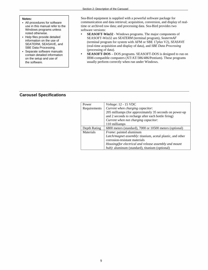
Sea-Bird equipment is supplied with a powerful software package forcommunication and data retrieval; acquisition, conversion, and display of real-time or archived raw data; and processing data. Sea-Bird provides twosoftware versions:• SEASOFT-Win32 - Windows programs. The major components of
SEASOFT-Win32 are SEATERM (terminal program), SeatermAF(terminal program for system with AFM or SBE 17plus V2), SEASAVE(real-time acquisition and display of data), and SBE Data Processing(processing of data).
• SEASOFT-DOS – DOS programs. SEASOFT-DOS is designed to run onIBM-compatible computers (XT/AT/386/486/Pentium). These programsusually perform correctly when run under Windows.
Carousel Specifications
PowerRequirements
Voltage: 12 - 15 VDCCurrent when charging capacitor:205 milliamps (for approximately 35 seconds on power-upand 2 seconds to recharge after each bottle firing)Current when not charging capacitor:110 milliamps
Depth Rating 6800 meters (standard), 7000 or 10500 meters (optional)Materials Frame: painted aluminum
Latch/magnet assembly: titanium, acetal plastic, and othercorrosion-resistant materialsHousing(for electrical and release assembly and mounthub): aluminum (standard), titanium (optional)
Notes:• All procedures for software
use in this manual refer to theWindows programs unlessnoted otherwise.
• Help files provide detailedinformation on the use ofSEATERM, SEASAVE, andSBE Data Processing.
• Separate software manualscontain detailed informationon the setup and use ofthe software.

Section 2: Description of the Carousel
10
Carousel Dimensions and Weights
Bottle Mount Stand CTD Extension Stand Total Package *Carousel Height, mm
(inches)Diameter, mm
(inches)Height,
mm (inches)Diameter, mm
(inches)Height, mm
(inches)Weight,kg (lbs)
Full Size SBE 32
12 bottle, 1.2 liter
12 bottle, 1.7 liter788 (31.0) 1201 (47.3) 68 (150)
12 bottle, 2.5 liter 1024 (40.3) 1438 (56.6) 79 (174)
12 bottle, 5 liter 820 (32.3) 1234 (48.6) 78 (172)
12 bottle, 8 liter 1024 (40.3) 1438 (56.6) 79 (174)
12 bottle, 10 liter 1189 (46.8) 1603 (63.1) 82 (182)
12 bottle, 12 liter 1316 (51.8)
991 (39.0) 991 (39.0)
1730 (68.1) 83 (184)
12 bottle, 20 liter 1351 (53.2) 164 (363)
12 bottle, 30 liter 1351 (53.2)1550 (61.0)
406 (16.0)
1549 (61.0) 1765 (69.5)171 (378)
24 bottle, 1.2 liter
24 bottle, 1.7 liter800 (31.5) 1214 (47.8) 95 (210)
24 bottle, 2.5 liter 1003 (39.5)
1143 (45.0) 406 (16.0) 1143 (45.0)
1417 (55.8) 106 (235)
24 bottle, 5 liter 869 (34.2) 1300 (51.3) 179 (397)
24 bottle, 8 liter 1072 (42.2) 1506 (59.3) 185 (410)
24 bottle, 10 liter 1224 (48.2) 1659 (65.3) 194 (430)
24 bottle, 12 liter 1351 (53.2)
1550 (61.0) 427 (16.8) 1549 (61.0)
1786 (70.3) 199 (440)
36 bottle, 12 liter 1654 (65.1) 2134 (84.0) - 1661 (65.4) 339 (750)
Compact SBE 32C
12 bottle,1.2 - 8 liter 965 (38.0) 966 (38.0) - 973 (38.3) 68 (150)
Subcompact SBE 32SC
12 bottle, 1.7 liter 788 (31.0) 800 (31.5) 50 (111)
12 bottle, 2.5 liter 991 (39.0)699 (27.5) -
1003 (39.5) 52 (114)
*Total package height = bottle mount stand + CTD extension stand (if applicable) + height of lifting bail above bottle mount stand
Height of lifting bail above bottle mount stand is approximately 8 mm (0.3 in.).Total package weight does not include bottles or CTD.

Section 2: Description of the Carousel
11
ConfigurationsReal-Time Configuration
• SBE 9plus CTD with SBE 11plus Deck Unit
• SBE 19, 19plus, or 25 CTD with SBE 33 Deck Unit
Note:For real-time operation,connection to two COM ports onthe computer is required. COM1(CTD data channel) and COM2(Carousel command channel) arethe defaults, and are shown in thediagrams for illustration only.You can use any two ports, inany order; set up the COM portconfiguration in SEASAVEto correspond.

Section 2: Description of the Carousel
12
Autonomous Configuration
• SBE 9plus CTD with SBE 17plus V2 SEARAM (Memory andAuto Fire Module)
• SBE 19, 19plus, or 25 CTD with PN 90208 Auto Fire Module

Section 3: Preparing the Carousel for Deployment
13
Section 3:Preparing the Carousel for DeploymentAssembling the SBE 32
The SBE 32C (compact model) and 32SC (sub-compact model) are shippedfrom Sea-Bird fully assembled. The assembly instructions apply only to thestandard, full-size SBE 32.
Parts and assembly procedure vary, depending on the number of bottles.Instructions follow for:• 12-bottle SBE 32• 24-bottle SBE 32
12-Bottle Full Size SBE 32
1. Place the lower guard ring on a flat surface on two 2” x 4” boards(as shown in photo). The boards lift the assembly for easy installation ofthe guard side bars (Step 7).
2. Set the lower adapter plate (adapter plate with bottle locator pinson its top surface) on the flange of the lower guard ring, aligning themounting holes.
3. The lifting bail is shipped installed on the pylon/hub assembly, to showthe arrangement of hardware. Remove the lifting bail and associatedhardware from the pylon/hub assembly for now, noting the arrangementof the hardware for later reinstallation.
4. Set the pylon/hub assembly on the lower adapter plate, aligning themounting holes. Secure the pylon/hub assembly and lower adapter plate tothe lower guard ring through the 1/2” holes (oversized holes will be usedfor the bail assembly later). Use four 1/2-13 x 3
1/2” socket head capscrews, 1/2” flat washers, 1/2” flat washers, 1/2” split lock washers, and1/2-13 hex nuts. Do not tighten completely.
Loweradapterplate Lower
guardring
Note:Place a small quantity of theNeverSeez Blue Moly compound(provided) on all screws, toprevent seizing.
Pylon/hubassembly

Section 3: Preparing the Carousel for Deployment
14
5. Set the upper adapter plate (adapter plate with holes to secure waterbottles to Carousel) on the pylon/hub assembly, aligning themounting holes.
6. Set the upper guard ring on the upper adapter plate, aligning the mountingholes. Secure the upper guard ring to the upper adapter plate andpylon/hub assembly through the 1/2” holes (oversized holes will be usedfor the bail assembly later). Use four 1/2-13 x 3
1/2” socket head capscrews, 1/2” flat washers, 1/2” flat washers, 1/2” split lock washers, and1/2-13 hex nuts. Do not tighten completely.
7. Place the six guard side bars between the upper and lower guard rings.Note that there are two types of side bars: one for upper guard ringpositions without a riser bar (A), and the other for positions with ariser bar (B).A. Connect the side bars to the upper guard ring, loosely installing the
1/4-20 x 11/2” flat head socket cap screws.B. Connect the side bars to the lower guard ring, installing the
1/4-20 x 11/2” flat head socket cap screws. Tighten these screws fully.C. Fully tighten the screws connecting the side bars and upper
guard ring.
Upperadapterplate
Upperguardring
Pylon / hubassembly
Riserbar
Sidebar
A B
Guardside bars
Section 3: Preparing the Carousel for Deployment
15
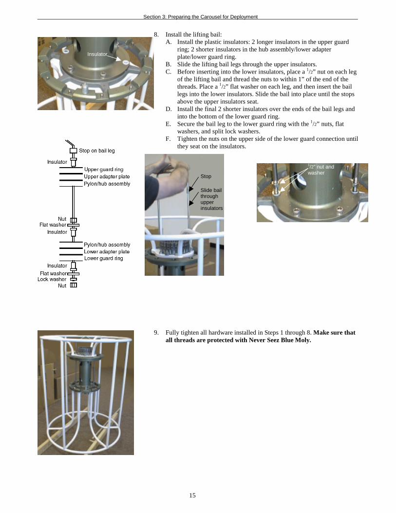
8. Install the lifting bail:A. Install the plastic insulators: 2 longer insulators in the upper guard
ring; 2 shorter insulators in the hub assembly/lower adapterplate/lower guard ring.
B. Slide the lifting bail legs through the upper insulators.C. Before inserting into the lower insulators, place a 1/2” nut on each leg
of the lifting bail and thread the nuts to within 1” of the end of thethreads. Place a 1/2” flat washer on each leg, and then insert the baillegs into the lower insulators. Slide the bail into place until the stopsabove the upper insulators seat.
D. Install the final 2 shorter insulators over the ends of the bail legs andinto the bottom of the lower guard ring.
E. Secure the bail leg to the lower guard ring with the 1/2” nuts, flatwashers, and split lock washers.
F. Tighten the nuts on the upper side of the lower guard connection untilthey seat on the insulators.
9. Fully tighten all hardware installed in Steps 1 through 8. Make sure thatall threads are protected with Never Seez Blue Moly.
Insulator
1/2” nut andwasher
Slide bailthroughupperinsulators
Stop

Section 3: Preparing the Carousel for Deployment
16
24-Bottle Full Size SBE 32
1. Place the lower guard ring on a flat surface on two 2” x 4” boards.The boards lift the assembly for easy installation of the guard side bars(Step 7).
2. Set the lower adapter plate (adapter plate with bottle locator pins on its topsurface) on the flange of the lower guard ring, aligning the mountingholes. Secure the adapter plate to the guard ring through six 1/2” holes inthe outer circle, using 1/2-13 x 3
1/2” socket head cap screws, 1/2” flatwashers, 1/2” flat washers, 1/2” split lock washers, and 1/2-13 hex nuts. Donot tighten completely at this time.
3. Set the pylon/hub assembly on the lower adapter plate, aligning themounting holes. Secure the pylon/hub assembly to the lower adapter platethrough the six 1/2” holes, using 1/2-13 x 2
1/2” socket head cap screws, 1/2”flat washers, 1/2” flat washers, 1/2” split lock washers, and1/2-13 hex nuts. Do not tighten completely at this time.
4. Install the four rods:A. The rods are shipped with its hardware installed, to show the
arrangement of the hardware. The bottom end of the rod has a locknut, flat washer, flat washer, lock washer, and nut. The nut should beapproximately 4” from the end of the rod. Remove the lock nut andflat washer from the bottom of the rod.
B. Insert the rod through the lower adapter plate and lower guard ringuntil the flat washer, lock washer, and nut rest on the adapter plate.Secure the rod by installing the flat washer and lock nut on theunderside of the lower guard ring.
C. Remove the remaining flat washer and lock nut from the top end ofthe rod.
5. Slide the upper adapter plate through the rods until it rests on thepylon/hub assembly. Secure the adapter plate to the pylon/hub assemblythrough the six countersunk 1/2” holes, using 1/2-13 x 2
1/2” socket headcap screws, 1/2” flat washers, and 1/2-13 lock nuts.
6. Slide the upper guard ring through the rods until it rests on the upperadapter plate. Install the four 1/2-13 lock nuts and 1/2” flat washers onthe rods.
Lowerguardring
Pylon/hubassembly
Lower guardring
Upper adapterplate
Bail leg (2)
Rod (4)
Lower adapterplate
Upper guardring
Note: The lifting bail, shown in thephoto, is not installed until Step 10.

Section 3: Preparing the Carousel for Deployment
17
7. Place the six guard side bars between the upper and lower guard rings.Note that there are two types of side bars: one for upper guard ringpositions without a riser bar (A), and the other for positions with ariser bar (B).
A. Connect the side bars to the upper guard ring, loosely installing the3/8-16 x 2” flat head socket cap screws.
B. Connect the side bars to the lower guard ring, installing the3/8-16 x 2” flat head socket cap screws. Tighten these screws fully.
C. Fully tighten the screws connecting the side bars and upperguard ring.
8. The lifting bail is shipped with the hardware installed on it, to show thehardware arrangement. Remove the hardware for now, noting thehardware arrangement for later reinstallation.
9. Install the lifting bail:A. Install the plastic insulators: two longer insulators in the upper guard
ring; two shorter insulators in the lower adapter plate.B. Place the 3/4” flat washers on the upper insulators.C. Slide the lifting bail through the flat washers and upper insulators.D. Before inserting into the lower insulators, place a 3/4” nut on each leg
of the lifting bail and thread the nuts to within 1” of the end of thethreads. Place a 3/4” flat washer on each leg, and then insert the baillegs into the lower insulators. Slide the bail into place until the stopsabove the upper insulators seat.
E. Install the final 2 shorter insulators over the ends of the bail legs andinto the bottom of the lower guard ring.
F. Secure the bail leg to the lower guard ring with the 3/4” nuts, flatwashers, and split lock washers.
G. Tighten the nuts on the lower adapter plate until they seat onthe insulators.
10. Fully tighten all hardware installed in Steps 1 through 9. Make sure thatall threads are protected with Never Seez Blue Moly.
A B
Guardside bars
Stop
Riserbar Side
barSidebar

Section 3: Preparing the Carousel for Deployment
18
Installing CTD Extension Stand and Mounting SBE 9plus CTDThe CTD extension stand is optional, and is used with the full size SBE 32when deployed with an SBE 9plus CTD. Note that the SBE 9plus is mountedhorizontally in the extension stand; see Appendix II: CTD Plumbing for pumpplacement and plumbing for a horizontal mount.
1. Mount the SBE 9plus in the extension stand as shown indrawing 40683.
2. Place the Carousel assembly on top of the CTD extension stand.
3. Secure the Carousel assembly to the CTD extension stand at 4 locationsusing the U-bolts.A. Wrap the supplied Teflon tape over the Carousel frame and extension
stand at each of the U-bolt locations.B. Install the 4 U-bolts and hardware (1 flat washer and 2 lock nuts per
U-bolt). Make sure that all threads are protected with Never SeezBlue Moly.
Mounting Instruments to CarouselAs described above, the SBE 9plus CTD is always mounted horizontally to theCarousel, using the CTD extension stand.
The SBE 19, 19plus, or 25 CTD can also be mounted in a horizontal positionwhen used with a full size SBE 32. These CTDs are mounted vertically in abottle position on the Carousel, when used with the SBE 32C or 32SC.
Additionally, a 90208 Auto Fire Module (AFM) or SBE 17plus V2 SEARAMcan be mounted vertically in a bottle position.
Mounting Bottles to Carousel1. Tilt the bottle to engage the lower adapter plate pin in the bottom of
the bottle mount.
2. Depress the bottle plunger, and rotate the bottle until the bottle plungerengages in the upper adapter plate.
CTD extensionstand
U-bolt (place Teflontape over barsbefore installing)
Carouselframe
Pin
Upperadapterplate
Loweradapterplate
Note:The SBE 32C and 32SC Carouselsare shipped from Sea-Bird with thebottles already mounted.
Note:Sea-Bird can provide a specialmounting fixture for verticalmounting in a bottle position.
Section 3: Preparing the Carousel for Deployment
19
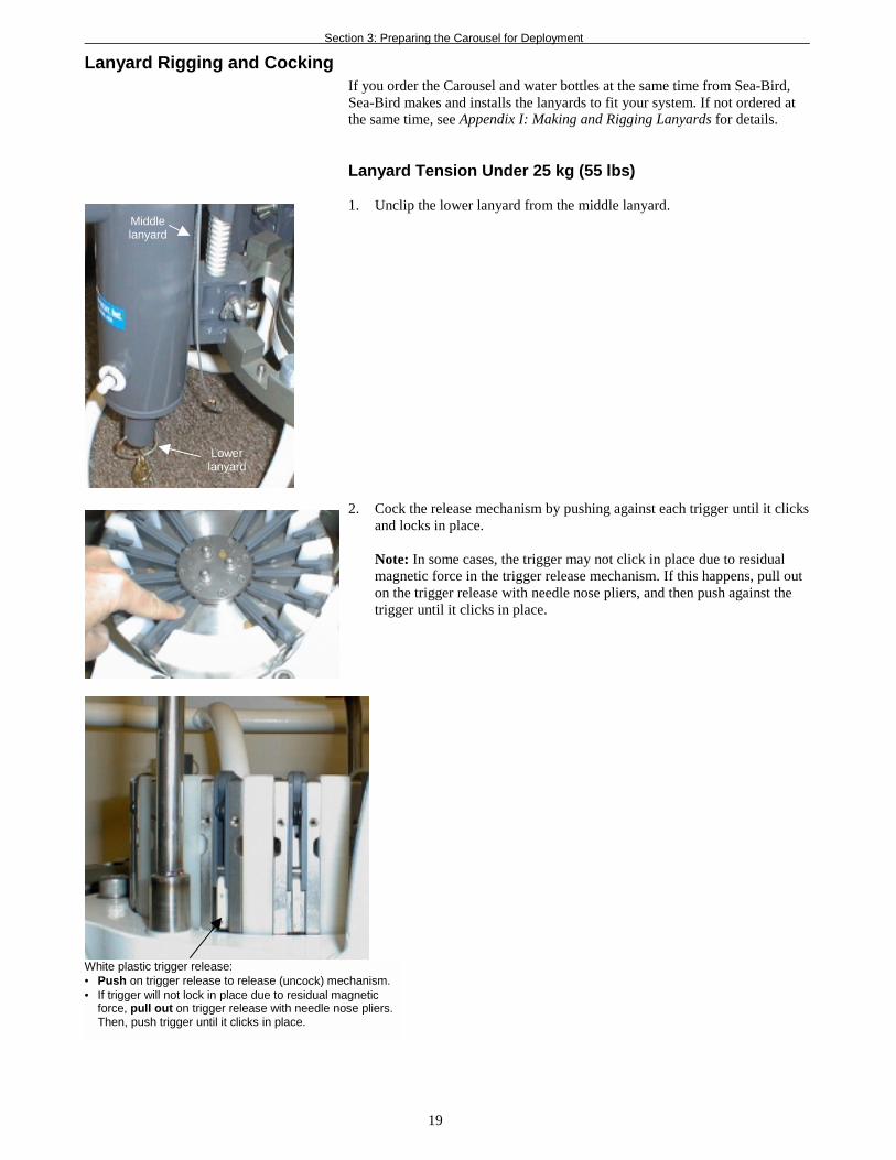
Lanyard Rigging and CockingIf you order the Carousel and water bottles at the same time from Sea-Bird,Sea-Bird makes and installs the lanyards to fit your system. If not ordered atthe same time, see Appendix I: Making and Rigging Lanyards for details.
Lanyard Tension Under 25 kg (55 lbs)
1. Unclip the lower lanyard from the middle lanyard.
2. Cock the release mechanism by pushing against each trigger until it clicksand locks in place.
Note: In some cases, the trigger may not click in place due to residualmagnetic force in the trigger release mechanism. If this happens, pull outon the trigger release with needle nose pliers, and then push against thetrigger until it clicks in place.
Middlelanyard
Lowerlanyard
White plastic trigger release:• Push on trigger release to release (uncock) mechanism.• If trigger will not lock in place due to residual magnetic
force, pull out on trigger release with needle nose pliers.Then, push trigger until it clicks in place.

Section 3: Preparing the Carousel for Deployment
20
3. If deploying reversing thermometers, rotate the thermometer rack andplace the thermometer lanyard loop over the upper lanyard, so that it restsagainst the upper lanyard ball.
4. Attach the upper lanyard to the trigger hook.
5. Clip the lower lanyard to the middle lanyard. The end cap handle shouldangle out away from the Carousel, not in towards the middle of theCarousel. Center the connection on the bottom end cap.• If the bottle has a handle, run the middle lanyard through the handle.
This will prevent the loss of either end cap in the event that the rubbertubing between the two end caps breaks.
• Some larger bottles have a small loop of monofilament on the handle.If so, run the middle lanyard through the monofilament - the loopensures a straighter path for the lanyard and positions the bottom endcap more favorably when it is in the cocked position.
Thermometerlanyard
Upper lanyard
Angling end cap handle away fromcenter of Carousel
Correct - connection centered onbottom end cap
Lowerlanyard
Middlelanyard
Running middle lanyardthrough handle
Middlelanyard
Upperlanyard
Incorrect - connection on side ofbottom end cap

Section 3: Preparing the Carousel for Deployment
21
Lanyard Tension Between 25 and 50 kg (55 and 110 lbs)
For water bottles with lanyard tensions in this range, rig the Carousel with asimple block and tackle type loop, reducing the tension on the trigger by half.
1. Cut a lanyard 7 1/4” (18 cm) long. Mark it in two places as shown.
2. Thread the lanyard through the pylon as shown. Place a nico-press sleeveon each end of the lanyard, aligning the sleeve with the marks so thatthere is approximately 6” (15.2 cm) of lanyard between the sleeves.
3. Follow the procedure above for a lower tension system, with thefollowing exception: Slide the upper lanyard loop over the high tensionrigging and attach the high tension rigging to the trigger hook.
5/8”(1.6 cm)
5/8”(1.6 cm)
6”(15.2 cm)

Section 4: Deploying and Operating the Carousel
22
Section 4: Deploying and Operatingthe Carousel
This section includes discussions of:
• Commands to the Carousel• System wiring, setup, and operation
Communications and CommandsDuring normal operation, commands are sent automatically to the Carouselby the system controlling the Carousel’s operation. These commands areincluded here for reference. All the command characters must be upper case(capital letters).
Commandsent to
CarouselDecimal Code Description
#SR 163 211 210 Go to home position (position #1).#SF 163 211 198 Fire next position (sequential firing).
#SNX 163 211 206 X Fire position X (first position is ‘1’), where X isin ASCII. For example:• #SN1 (decimal 163 211 206 177) -
fire position 1• #SN2 (decimal 163 211 206 178) -
fire position 2• #SN< (decimal 163 211 206 188) -
fire position 12• #SNH (decimal 163 211 206 200) -
fire position 24#SBX 163 211 194 X (For Carousel with interface for operation with
SBE 33 Deck Unit) Set Carousel to CTDcommunication baud rate:• #SB0 (decimal 163 211 194 176) - 600 baud• #SB1 (decimal 163 211 194 177) - 1200 baud• #SB2 (decimal 163 211 194 178) - 2400 baud• #SB3 (decimal 163 211 194 179) - 4800 baud
The Carousel sends one of these replies upon receipt of a reset (go to homeposition) or bottle fire command:
Reply fromCarousel Description
6 33 6 At home position, next bottle to fire is #1.6 35 6 Received invalid bottle number.6 45 6 Did not confirm bottle fire.6 X 6 Fired bottle #(X-48). For example:
• 6 49 6 - fired bottle #1• 6 50 6 - fired bottle #2• 6 72 6 - fired bottle #24
Note:Separate software manuals andHelp files contain detailedinformation on installation, setup,and use of Sea-Bird’s terminalprograms, real-time dataacquisition software, and dataprocessing software.
Note:When controlling the Carouselwith the SBE 17plus V2, you canmanually send these commandsto the SBE 17plus V2 to testthe system.

Section 4: Deploying and Operating the Carousel
23
System Setup and OperationSystem setup and operation is summarized below for each of the four methodsof controlling the Carousel:• SBE 11plus Deck Unit (real-time operation with SBE 9plus CTD)• SBE 33 Deck Unit (real-time operation with SBE 19, 19plus, or 25 CTD)• SBE 17plus V2 SEARAM (autonomous operation with SBE 9plus CTD)• 90208 Auto Fire Module (autonomous operation with SBE 19, 19plus, or
25 CTD, or with no CTD)
See the controller manual for detailed setup and operation instructions.
SBE 11plus Deck Unit
Wiring:
• Carousel 6-pin to SBE 9plus JT7• SBE 9plus JT1 to Sea Cable on SBE 11plus Deck Unit• See SBE 9plus manual for connections to auxiliary sensors, and see
SBE 11plus manual for connections to computer and auxiliary equipment
Setup and Operation in SEASAVE:
1. In the Configure menu, select Water Sampler Configuration.Set the total number of bottles to be closed, water sampler type, andfiring sequence.
2. (If using a NMEA navigation device) In the Configure menu, selectNMEA [Lat/Lon] Interface. Select how to store the NMEA Interface data.
3. Perform any other desired setup in the Configure andScreenDisplay menus.
4. In the RealTime Data menu, select Start Acquisition.A. Select the CTD configuration (.con) file.B. Enter the desired filename and location for the data file.C. Configure the computer COM ports:
• CTD Data COMM Port connects to SBE 11plus Interface(RS-232 or IEEE-488)
• Deck Unit Modem Comm Port connects to SBE 11plusModem Channel
• CTD Data Baud Rate is the baud rate that the SBE 11plus uses totransmit the CTD data to the computer. Enter a value thatmatches your SBE 11plus. For older units (SBE 11 and 11plus),the baud rate is set by a dip switch in the deck unit to 19200(default) or 9600. In newer units (SBE 11plus V2), the baud rateis always set to 19200.
D. Click Start Acquire.
5. To fire a bottle from SEASAVE:• Press Ctrl F3, or• In the View menu, select Fire Bottle Control. The Bottle Fire dialog
box appears (you can leave this open throughout the cast).Click Fire Bottle.
6. To fire a bottle from the SBE 11plus front panel:A. Press Home/Arm.B. Press Fire. Carousel fires bottle 1, and then fires in sequential order
each time that Fire is pressed.
Note:The .con file defines the CTD -auxiliary sensors integrated with theinstrument, and channels, serialnumbers, and calibration dates andcoefficients for all the integratedsensors (conductivity, temperature,and pressure as well as auxiliarysensors). Additionally, the .con filedefines if optional NMEA Interfacedata is to be appended to the CTDdata. SEASAVE (and our dataprocessing software) uses theinformation in the .con file to interpretand process the raw data.If the .con file does not match theactual instrument configuration,the software will not be ableto interpret and process thedata correctly.

Section 4: Deploying and Operating the Carousel
24
SBE 33 Deck Unit
Wiring:
• Carousel 2-pin to SBE 33• Carousel 4-pin to CTD data I/O connector• See CTD manual for connections to auxiliary sensors, and see
SBE 33 manual for connections to computer and auxiliary equipment
Setup and Operation in SEASAVE:
1. In the Configure menu, select Water Sampler Configuration.Set the total number of bottles to be closed, water sampler type, andfiring sequence.
2. (If using a NMEA navigation device) In the Configure menu, selectNMEA [Lat/Lon] Interface. Select how to store the NMEA Interface data.
3. Perform any other desired setup in the Configure andScreenDisplay menus.
4. In the RealTime Data menu, select Start Acquisition.
A. Select the CTD configuration (.con) file.B. Enter the desired filename and location for the data file.C. Configure the computer COM ports. CTD Data COMM Port
connects to SBE 33 Serial Data; Deck Unit Modem Comm Portconnects to SBE 33 Carousel Data. Baud Rate between SBE 33 andComputer and Baud Rate between SBE 32 and CTD must agree withCTD setup and SBE 33 dip switch setting.
D. Click Start Acquire.
5. If the CTD is not already on, SEASAVE prompts you to turn on theCTD’s magnetic switch.
6. To fire a bottle from SEASAVE:• Press Ctrl F3, or• In the View menu, select Fire Bottle Control. The Bottle Fire dialog
box appears (you can leave this open throughout the cast).Click Fire Bottle.
7. To fire a bottle from the SBE 33 front panel:
A. Set the Bottle to Fire switch to 00 and then press Reset.B. To fire in random order, set the Bottle to Fire switch to the desired
bottle and press Fire.C. To fire in sequential order, set the Bottle to Fire switch to 99 before
firing the first bottle. Press Fire. Carousel fires bottle 1, and then firesin sequential order each time that Fire is pressed.
Note:The .con file defines the CTD -auxiliary sensors integrated with theinstrument, and channels, serialnumbers, and calibration dates andcoefficients for all the integratedsensors (conductivity, temperature,and pressure as well as auxiliarysensors). Additionally, the .con filedefines if optional NMEA Interfacedata is to be appended to the CTDdata. SEASAVE (and our dataprocessing software) uses theinformation in the .con file to interpretand process the raw data.If the .con file does not match theactual instrument configuration,the software will not be ableto interpret and process thedata correctly.
Note:The CTD optical isolation feature(SBE 25 - standard; SBE 19 -optional) must be disabled whenthe CTD is used with the Carousel:1. Open the CTD main housing.2. Solder a jumper wire across the
neon bulb on the above board.See the CTD manual for details onaccessing the above board and forthe board schematic.This note is not applicable to theSBE 19plus.

Section 4: Deploying and Operating the Carousel
25
SBE 17plus V2 SEARAM
The SEARAM fires bottles on upcast only, at predefined pressures.
Wiring:
• Carousel 6-pin to SBE 17plus V2 6-pin connector that is directly acrossfrom switch plunger
• SBE 17plus V2 other 6-pin connector to SBE 9plus• See SBE 9plus manual for connections to auxiliary sensors
Setup and Operation:
1. Connect the SEARAM to the computer using the data I/O cable.In SeatermAF:A. In the Configure menu, select the SBE 17plus.
• Set communication parameters.• Set auto fire parameters and select/define the CTD configuration
(.con) file.B. Click the Connect button.C. Set the time and date.D. Set memory parameters; note that the definition of auxiliary sensor
channels must match the .con file.E. Click the Program button to send the auto fire parameters to the
SEARAM.F. Click the Arm button to enable the SEARAM to fire bottles.
2. Replace the I/O cable with the dummy plug and locking sleeve.
3. Push in the SEARAM’s switch plunger to start logging.
90208 Auto Fire Module (AFM)
The AFM closes bottles on upcast, on downcast, when stationary, or onelapsed time.
Wiring:
• Carousel to AFM JB2• AFM JB1 to CTD data I/O connector• See CTD manual for connections to auxiliary sensors
Setup and Operation:
1. Connect the AFM to the computer using the data I/O cable.In SeatermAF:A. In the Configure menu, select the AFM with the applicable CTD.
• Set communication parameters.• Set auto fire parameters and select/define the CTD configuration
(.con) file.B. Click the Connect AFM button to communicate with the AFM.C. Set the date and time.D. Click the Program button to send the auto fire parameters to
the AFM.E. Click the Arm button to enable the AFM to fire bottles.
2. Replace the I/O cable with the dummy plug and locking sleeve.
3. Turn on the CTD’s magnetic switch to start logging.
Note:The .con file defines the CTD -auxiliary sensors integrated with theinstrument, and channels, serialnumbers, and calibration dates andcoefficients for all the integratedsensors (conductivity, temperature,and pressure as well as auxiliarysensors). The SEARAM uses thepressure sensor coefficients tocalculate pressure from the CTDpressure frequency data. Thesepressures are used to determinewhen to close bottles, based on theuser-input bottle position and closureparameters. If the .con file does notmatch the actual instrumentconfiguration, the SEARAM willnot be able to interpret andprocess the data correctly.
Note:The .con file defines the CTD -auxiliary sensors integrated with theinstrument, and channels, serialnumbers, and calibration dates andcoefficients for all the integratedsensors (conductivity, temperature,and pressure as well as auxiliarysensors). SeatermAF uses thepressure sensor coefficients tocalculate raw pressure sensor outputfrom the user’s closure pressureentries in the Configuration Optionsdialog box. These pressures are usedto determine when to close bottles,based on the user-input bottleposition and closure parameters. Ifthe .con file does not match theactual instrument configuration,the AFM will not be able tointerpret and process the datacorrectly.

Section 4: Deploying and Operating the Carousel
26
RecoveryRinse the Carousel, CTD, and auxiliary equipment and sensors withfresh water.WARNING!
Pressure housings may floodunder pressure due to dirty ordamaged o-rings, or other failedseals, causing highly compressedair to be trapped inside. If thishappens, a potentially life-threatening explosion can occurwhen the instrument is brought tothe surface.If the Carousel, CTD, or auxiliaryequipment/sensors areunresponsive to commands orshows other signs of flooding ordamage, carefully secure theinstrument in a location away frompeople until it has beendetermined that abnormal internalpressure does not exist.Contact Sea-Bird for assistancewith procedures for safelyrelieving internal pressure.

Section 5: Routine Maintenance
27
Section 5: Routine MaintenanceThis section reviews corrosion precautions and routine maintenance.The reliability of the Carousel is sustained by establishing properhandling practices.
Corrosion Precautions/CleaningRinse the entire Carousel with fresh water after each cast.
The Carousel’s trigger mechanism is made of titanium. The titanium is coatedwith Tiodizing; this product is similar to anodizing aluminum. TheTiodized surface is water lubricating and should never beoiled with petroleum or silicon-based products. Rinse the triggermechanism with fresh water after each cast and clean it periodically withwarm, soapy water. If the trigger mechanism sticks after this cleaning, removethe latch assembly and immerse the whole assembly in warm, soapy water.See Removing / Replacing Latch Mechanism below.
Large zinc anodes provide corrosion protection:• SBE 32C and 32SC - two each in lower adapter plate, lower guard ring,
upper adapter plate, upper guard ring; one on pylon/hub assembly• SBE 32 (standard)
12-bottle size - three each on lower guard ring and upper guard ring;two on lower adapter plate; one on pylon/hub assembly24-bottle size - three each in lower adapter plate, lower guard ring,upper adapter plate, upper guard ring; one on pylon/hub assembly
• CTD extension stand (if used) - twoCheck the anodes occasionally to verify that they are securely fastened andhave not eroded.
All screws that are exposed to seawater have been generously lubricated withan anti-seize compound, Never-Seez Blue Moly, manufactured by Bostik(available through marine hardware stores). When disassembling/reassemblingthe Carousel, re-lubricate these screws with Blue Moly or equivalent.This compound is electrically conductive, so be careful not to get it oncircuit boards.
Note:The anti-seize compound ismolybdenum disulfide and pure nickelflake in pressure-resistant premiumgrade grease, formulated withoutgraphite, lead, or copper.See Bostik’s website(http://www.bostik.com/pdf/distribution/N2BlueMoly.pdf) for the most up-to-date specifications; a copy of Bostik’scurrent product data sheet is includedin Appendix III for your convenience.

Section 5: Routine Maintenance
28
Removing/Replacing Latch Assembly
Removing Latch Assembly
1. Remove the three socket hex head screws, lock washers, and flat washersfrom the top of the latch assembly. Lift the latch assembly off the pylon.
2. Remove individual triggers if desired:A. Mark the location of trigger 1 (from the retainer disk) on the trigger
mount disk to aid in reassembly.B. Remove the Phillips-head screws (eight for 32C and 32SC, six for
full-size 32). Lift the retainer disk from the top of the latch assembly.C. Pull the desired trigger(s) horizontally from the trigger mount disk.
Mark the trigger(s) to aid in reassembly.
Replacing Latch Assembly
1. Replace the triggers on the trigger mount disk.
2. Place the retainer disk on the triggers, aligning the mark you made fortrigger 1 on the trigger mount disk with trigger 1 on the retainer disk.Verify that the triggers are properly seated in the grooves and that the diskis flat. Reinstall the Phillips-head screws loosely. Tighten the screws,working in a diagonal pattern to ensure the disk remains properly seated.
3. Line up the latch assembly alignment hole with the pylon alignment pin.Seat the latch assembly on the pylon. Reinstall the three socket hex headscrews, lock washers, and flat washers.
Screws(3)
Pull trigger horizontallyto remove
Triggermount disk
Alignmenthole forposition 1 forreplacementon pylon
Retainerdisk andPhillips-headscrews
Alignment pinfor position 1

Section 5: Routine Maintenance
29
Removing Center Pylon1. Remove the lifting bail.
A. Remove the hardware from underneath the lower guard ring.B. Begin to pull the lifting bail up, until it is above the lower guard
ring/adapter plate/hub assembly connection.C. Remove the hardware from the legs of the lifting bail.D. Pull the lifting bail out of the upper guard ring.
2. Remove the 6 socket hex head cap screws and washers from the undersideof the upper adapter plate. Pull the trigger assembly with the pylon up andout of the Carousel frame.
Note:There are plastic insulators onthe underside of the followingconnections:• Lower guard ring/adapter plate/hub
assembly - for lifting bail• Upper adapter plate - for pylon
Verify that the insulators have notfallen out before reinstalling the pylonand lifting bail.

Glossary
30
GlossaryPCB – Printed Circuit Board.
SBE Data Processing – Sea-Bird’s WIN 95/98/NT data processingSoftware, which calculates temperature, conductivity, and optional pressure,and derives variables such as salinity and sound velocity.
Scan – One data sample containing temperature, conductivity, pressure, andoptional auxiliary inputs.
SEASAVE – Sea-Bird’s WIN 95/98/NT software used to acquire, convert,and display real-time or archived raw data.
SEASOFT-DOS – Sea-Bird’s complete DOS software package, whichincludes software for communication, real-time data acquisition, and dataanalysis and display.
SEASOFT-Win32– Sea-Bird’s complete Win 95/98/NT software package,which includes software for communication, real-time data acquisition, anddata analysis and display. SEASOFT-Win32 includes SEATERM,SeatermAF, SEASAVE, SBE Data Processing, and PLOT39.
SEATERM – Sea-Bird’s WIN 95/98/NT terminal program used tocommunicate with the SBE 11plus or 33 Deck Unit to set up the instruments.
SeatermAF – Sea-Bird’s WIN 95/98/NT software used to communicate withthe SBE 17plus V2, or with the AFM and a CTD (SBE 19, 19plus, or 25)connected to the AFM to set up the instruments.
Appendix I: Making and Rigging Lanyards
31
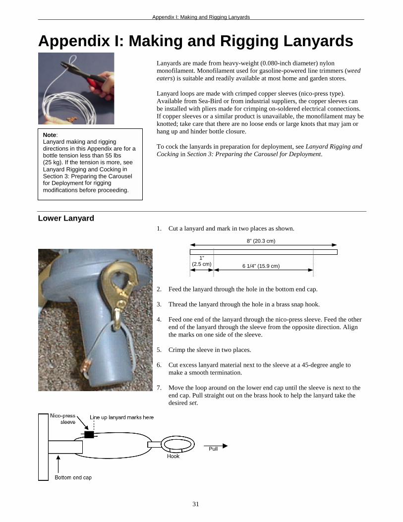
Appendix I: Making and Rigging LanyardsLanyards are made from heavy-weight (0.080-inch diameter) nylonmonofilament. Monofilament used for gasoline-powered line trimmers (weedeaters) is suitable and readily available at most home and garden stores.
Lanyard loops are made with crimped copper sleeves (nico-press type).Available from Sea-Bird or from industrial suppliers, the copper sleeves canbe installed with pliers made for crimping on-soldered electrical connections.If copper sleeves or a similar product is unavailable, the monofilament may beknotted; take care that there are no loose ends or large knots that may jam orhang up and hinder bottle closure.
To cock the lanyards in preparation for deployment, see Lanyard Rigging andCocking in Section 3: Preparing the Carousel for Deployment.
Lower Lanyard1. Cut a lanyard and mark in two places as shown.
2. Feed the lanyard through the hole in the bottom end cap.
3. Thread the lanyard through the hole in a brass snap hook.
4. Feed one end of the lanyard through the nico-press sleeve. Feed the otherend of the lanyard through the sleeve from the opposite direction. Alignthe marks on one side of the sleeve.
5. Crimp the sleeve in two places.
6. Cut excess lanyard material next to the sleeve at a 45-degree angle tomake a smooth termination.
7. Move the loop around on the lower end cap until the sleeve is next to theend cap. Pull straight out on the brass hook to help the lanyard take thedesired set.
8” (20.3 cm)
6 1/4” (15.9 cm)
1”(2.5 cm)
Pull
Note:Lanyard making and riggingdirections in this Appendix are for abottle tension less than 55 lbs(25 kg). If the tension is more, seeLanyard Rigging and Cocking inSection 3: Preparing the Carouselfor Deployment for riggingmodifications before proceeding.

Appendix I: Making and Rigging Lanyards
32
Upper LanyardThe overall lanyard length is dependent on the bottle type and size and the sizeof the Carousel. Some trial and error will be needed to determine the correctlength. General directions follow.
1. Cut a lanyard and mark in two places as shown.
2. Feed both ends of the lanyard through one end of a nico-press sleeve,leaving a loop (this loop will hook onto the pylon for rigging). Adjust thelanyard ends so that one end hangs below the other by 2” (5.1 cm).Adjust the nico-press sleeve position so that the loop measures1 1/4” (3.2 cm) from the end of the sleeve to the end of the loop.Do not crimp the sleeve.
3. The plastic lanyard ball has a hole drilled through it; the opening on oneside is slightly larger than the other. Feed both ends of the lanyard throughthe larger hole and work the ball up on the lanyard until it rests against thenico-press sleeve.
4. Feed the longer end of the lanyard through the hole in the top end cap.
5. Feed the ends of the lanyard through the nico-press sleeve in oppositedirections. Align the marks on one side of the sleeve. Crimp this sleeveonly; do not crimp the other sleeve yet. Cut excess lanyard material nextto the sleeve at a 45-degree angle to make a smooth termination.
6. Adjust the ball and other sleeve so that the tension is taken up evenly byboth legs of the lanyard. Crimp the sleeve now.
7. Test the assembly by placing the lanyard loop over the appropriate triggerhook. The end cap should be held in the correct cocked position. If not,remake the lanyard, adjusting measurements as required.
10 5/8” (27 cm)
1”(2.5 cm)

Appendix I: Making and Rigging Lanyards
33
Middle LanyardThe middle lanyard connects the upper and lower lanyards. The overalllanyard length is dependent on the bottle size. Some trial and error will beneeded to determine the correct length. General directions follow.
1. Cut a lanyard approximately 12” (31 cm) longer than the bottle. Mark it intwo places as shown.
2. Feed both ends of the lanyard through one end of a nico-press sleeve,leaving a loop (this loop will hook onto the bottom end cap hook). Alignthe marks on the side of the sleeve opposite the loop. Crimp the sleeve.Cut excess lanyard material next to the sleeve at a 45-degree angle tomake a smooth termination.
3. Place the upper lanyard’s loop on the trigger hook so that it is in itscocked position. Place a 2” (5.1 cm) wide wooden spacer in the top bottlemouth for safety.
4. Place the other wooden spacer in the bottom bottle mouth. The end caphandle should angle out away from the Carousel, not in towards themiddle of the Carousel.
5. Clip the middle lanyard loop into the lower lanyard snap hook.
6. If the bottle has a handle, run the end of the middle lanyard through thehandle. This will prevent the loss of either end cap in the event that therubber tubing between the two end caps breaks.
7. Verify that the bottle end caps are cocked at the correct angle.
8. Thread the end of the middle lanyard through a nico-press sleeve.
9. Thread the end of the middle lanyard through the loop on the upperlanyard. Bring the end of the middle lanyard back through the nico-presssleeve, capturing the loop in the upper lanyard.
10. Adjust the middle lanyard length so that it takes up the tension on thebottom end cap. Adjust the nico-press sleeve position so that the upperloop is about 1” (2.5 cm) long. Crimp the sleeve. Cut excess lanyardmaterial at a 45-degree angle to make a smooth termination.
11. Remove the wooden spacers. Both the top and bottom end caps should beheld in the proper cocked position. If they are not, remake the middlelanyard, adjusting measurements as required.
5 1/4” (13.4 cm)
1”(2.5 cm)
Middlelanyard
Upperlanyard

Appendix I: Making and Rigging Lanyards
34
Reversing Thermometer LanyardThe reversing thermometer lanyard attaches to the upper lanyard. The overalllanyard length is dependent on the bottle size and the type of thermometer.Some trial and error will be needed to determine the correct length. Generaldirections follow.
1. Place the upper lanyard’s loop on the trigger hook so that it is in itscocked position. Place a 2” (5.1 cm) wide wooden spacer in the bottlemouth for safety.
2. Measure the distance from the hole in the reversing thermometer to theball on the upper lanyard. Add about 6” (15.2 cm) to this length and cut apiece of lanyard.
3. Holding the reversing thermometer in the cocked position, thread one endof the lanyard through a nico-press sleeve, through the top hole in thereversing thermometer, and back through the nico-press sleeve. Adjust thesleeve until the loop fits snugly around the reversing thermometer hole.Crimp the sleeve. Cut excess lanyard material next to the sleeve at a45-degree angle to make a smooth termination.
4. Run the other end of the lanyard through a nico-press sleeve, around theupper lanyard loop (do not go through the loop), and back through thenico-press sleeve. Adjust the lanyard length until all the slack is taken outof the lanyard and the loop takes up tension on the upper lanyard ball.Adjust the nico-press sleeve position so that the loop is about 1 1/2”(3.8 cm) long. Crimp the sleeve. Cut excess lanyard material next to thesleeve at a 45-degree angle to make a smooth termination.
5. With the wooden spacer still in place for safety, release the trigger hookby pushing on the white plastic release. The reversing thermometerlanyard should fall away from the upper lanyard and the thermometershould spin to its reading position.
Note:Once the bottle associated with areversing thermometer has fired,the reversing thermometer lanyardis free and could potentiallyinterfere with the properdeployment of another bottleposition. Depending onthermometer and bottle type,devise a method to capture thereversing thermometer lanyard afterthe bottle fires using a rubber bandor some additional lanyard material.
White plastic trigger release

Appendix II: CTD Plumbing
35
Appendix II: CTD PlumbingAn SBE 9plus CTD that is deployed with the Carousel is mounted in ahorizontal position. Pump placement and plumbing for a horizontal mount isdifferent than that for a vertical mount. This appendix covers converting avertical mount CTD for horizontal use with a Carousel, and converting ahorizontal mount CTD from the Carousel to a stand-alone vertical mount.
Horizontal Mount• Configure the system as follows:
! Place the DO sensor intake above the temperature/conductivitysensors.
! Place the pump above the DO sensor.! Orient the pump with the exhaust outlet corner up.! Failure to configure the system in this manner can trap air, preventing
the pump from working properly.• Place a 13 mm (0.5 inch) piece of the 9.5 mm ID Tygon tubing at the DO
sensor intake and exhaust. Slide the larger diameter tubing (13 mm ID)over the smaller diameter tubing to provide tight seals.
The details are shown schematically below and in photos on the next page.
Note:An SBE 19, 19plus, or 25 used withthe full size SBE 32 can also bemounted horizontally; they aremounted vertically when used withthe SBE 32C or 32SC. Theguidelines for the SBE 9plus apply tothese CTDs as well.

Appendix II: CTD Plumbing
36
Temperature sensor
Overall View
Conductivity sensorPump(vertically aboveDO sensor)
DO sensor(plenum intake verticallyabove temperature/conductivity sensors)
Tygontubing
Details
Slide larger diameterTygon tubing oversmaller diameterTygon tubing to providetight seal at DO sensor
Pump exhaust –above DOsensor and TC Duct intake,oriented as shown below
TC Duct intakeQuick releasecoupling
Orient with cornervertically abovepump intake
Appendix II: CTD Plumbing
37
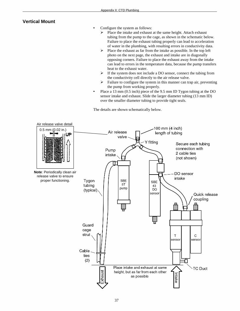
Vertical Mount• Configure the system as follows:
! Place the intake and exhaust at the same height. Attach exhausttubing from the pump to the cage, as shown in the schematic below.Failure to place the exhaust tubing properly can lead to accelerationof water in the plumbing, with resulting errors in conductivity data.
! Place the exhaust as far from the intake as possible. In the top leftphoto on the next page, the exhaust and intake are in diagonallyopposing corners. Failure to place the exhaust away from the intakecan lead to errors in the temperature data, because the pump transfersheat to the exhaust water.
! If the system does not include a DO sensor, connect the tubing fromthe conductivity cell directly to the air release valve.
! Failure to configure the system in this manner can trap air, preventingthe pump from working properly.
• Place a 13 mm (0.5 inch) piece of the 9.5 mm ID Tygon tubing at the DOsensor intake and exhaust. Slide the larger diameter tubing (13 mm ID)over the smaller diameter tubing to provide tight seals.
The details are shown schematically below.
Air release valve detail
Note: Periodically clean airrelease valve to ensure
proper functioning.
0.5 mm (0.02 in.)

Appendix III: Never-Seez Blue Moly Data Sheet
38
Appendix III: Never-Seez Blue MolyData SheetSee Bostik’s website (http://www.bostik.com/pdf/distribution/N2BlueMoly.pdf) for the most up-to-date specifications.

Appendix III: Never-Seez Blue Moly Data Sheet
39

Index
40
IndexAAbout Sea-Bird · 5Anodes · 27Application notes · See attachments at end of manualAssembly instructions · 13Auto Fire Module · 12, 25Autonomous operation · 12, 25
BBlue Moly · 27, 38
CCenter pylon removal · 29Cleaning · 27Commands · 22Configurations · 11Corrosion precautions · 27CTD extension stand · 18CTD mounting · 18CTD plumbing · 35
DDeployment
installation · 23preparing for · 13
Description · 7Dimensions · 10
EExtension stand · 18
GGlossary · 30
LLanyards · 19, 31Latch replacement · 28
MMaintenance · 27Mounting CTD · 18
NNever-Seez Blue Moly · 27, 38
OOperation · 23
PPlumbing · 35Pressure test certificate · See attachments at end of manualPylon removal · 29
RReal-time operation · 11, 23, 24Recovery · 26
SSBE 11plus Deck Unit · 11, 23SBE 17plus V2 SEARAM · 12, 25SBE 19 CTD · 11, 12, 24, 25SBE 19plus CTD · 11, 12, 24, 25SBE 25 CTD · 11, 12, 24, 25SBE 33 Deck Unit · 11SBE 9plus CTD · 11, 12, 23, 25SBE Data Processing · 9Schematics · See attachments at end of manualSEASAVE · 9SEASOFT · 9SEATERM · 9Service information · See attachment at end of manualSoftware · 9Specifications · 9System description · 7
UUnpacking Carousel · 6
WWarranty · See attachment at end of manualWeights · 10