Embed Size (px)
Citation preview

Milking Machines

Milking Machines -
By Oscar Erf - Owing to the great progress that has been made in the dairy in-
dustry within the last few years, there has come such a great de- mand for milkers that dairymen are unable to secure them at a compensation that will allow a fair margin of profit. The confine- ment and nature of the work frequently make milkers discontented and cause them to seek other work which perhaps is more pleas- ant to them. With this condition-one of the greatest draw- backs in the dairy business-it is quite essential for many western dairymen either to discontinue the dairy business or to secure an apparatus that will do the milking, for this seems to be the most objectionable part of the dairy business.
Within recent years a great many inventors have exerted their energies in this direction and milking machines have been in- vented that are practical under present existing conditions. The introduction of milking machines has become a popular subject for discussion, and it is plainly evident that it will be a marked stimu- lus to the dairy industry.
The number of inquiries on this subject has become so great that it is deemed advisable to present a brief history of the evolu- tion of milking machines, which will indicate that some inventors have been at work along this line for many years ; that many different kinds of complicated contrivances have been invented and patented; and that many schemes upon which inventors have been working have been tried and found to be impractical. We there- fore aim to give an illustration and brief description of many of the important milking machines and parts of them that have been de- vised. The information has been gathered from various sources, chiefly, however, from reports of the Patent Department, Washing- ton, D. C.
THE EVOLUTION OF MILKING MACHINES
While we have intimations that inventors have been at work with milking machines as far back as 1819, and later in 1837 and 1854,* we have been able to obtain neither a good description nor an il- lustration of these machines. The simplest scheme for milking,
2 MILKING MACHINES
aside from hand milking, of which we have reference, is the use of straws. These straws are inserted into the cow's teat and the milk allowed to run from the milk cistern. Of course, straws are more or less contaminated and soon will injure the udder of the
Real earnest work along the line of milking machines began in 1878, from which date we aim to show the progress of the work. There are three principles upon which milking machines are con- structed :
First, the milk tube is an apparatus that provides for an open- ing into the milk cistern and allows the milk to flow from the udder. While this system is practical in some instances, as in diseased udders, it however becomes dangerous and impractical for average dairy conditions owing to the fact that it is essential to sterilize and to keep sterilized that part of the apparatus which is to be inserted into the udder.
The second principle is by pressure applied at the base of the teat, where it is attached to the udder, which closes the duct of the teat, and by applying a continuous downward pressure forces out the milk contents. Hand milking is an example of this prin- ciple.
The third principle is by suction, the teat being placed in cups from which the air is exhausted, producing a vacuum. Hence, the pressure of the air on the udder tends to force the milk into the teat and into the vacuum chamber. This suction is produced by pumps, and the principle is illustrated by the calf sucking the teat. A calf while sucking exerts a small amount of pressure in connection with suction, and in some of the modern milking ma- chines this operation is reproduced.
While some of these machines have been invented for many years and have worked with a certain degree of success, the true principle of imitating the action of the calf's mouth on the teat was not invented until suction was produced at intervals. These intervals are known as pulsations. The intervals produced by the calf are due to the fact that the calf is obliged to take its breath and swallow, which relieves the teat of the suction at that moment, and allows the blood of the teat, which has been drawn down by suction, to flow back. These pulsations have been reproduced in the suction principle and aid materially in the success of the ma- chine.
cow.
MILK TUBES
No. 1. The first milk tube placed upon the market was invented by Mr. George, of New York, in 1878. It consisted of a teat tube or


No. 1 was made by Mr. Mayor, of Haynesville, Mo., in 1878, and consists of a rubber tube in which are two slotted metal half tubes, one stationary, the other movable, each having their upper ends rounded off upon the convex side. A bent, or U-shaped spring is fastened to the stationary tube and has a projection ex- tending toward the movable one so that when force is applied to the spring the half tubes are drawn together and the teats com- pressed. See Plate 2..
No. 2 is a machine patented by Mr. Frazey, of Jersey City, N. J., in 1882, and is composed of spherical tubes or bulbs having openings into which the teat is placed. These bulbs are connected by a neck or tube to a milk receiver, which contains a strainer through which the milk passes before reaching the milk vessel. See Plate 2.


No. 3 is a milking appliance placed on the market by John Ny- rop, of Copenhagen, Denmark, in 1885. It has a bent arm having a handle at the lower end, and at the upper a plate beneath which a cup is fastened, whose upper edges are formed of corrugated in- wardly curved horns. An arm is pivoted at the end of the bent bar, and has two inwardly projecting lips at its outer part con- nected by a pin. A handle is loosely to the arm. A attached spring is fastened at one end to the pin between the lips; to the other is attached an arm having bifurcated ends straddling the edges of the plate and horn. A yielding roller is journalled be- tween the upper ends of the bifurcated arm, travelling upon and bearing against the inner sides of the plate and its horns. See Plate 2.
No 4. is the Beyer and Rohde machine, made at Mishicott,, Wis., in 1886, and is very complicated, having a main frame to which an auxiliary frame is attached, and upon the latter is a pair of milking cylinders, each provided with a hinged shield, a detach- able pressure plate, spout leading to the delivery trough, a series of yielding, automatically adjustable rolls which revolve within the milk cylinders. Adjustable base plates support the rolls. A suitable shaft, levers and gearing are provided for transmitting motion to the yielding rolls. See Plate 2.
No. 5 is another Beyer & Rohde machine, similar to the one above, but in addition to the rolls there are pressure cushions stuffed with pliable material and each having an end secured to the milk cylinders. Non-porous sacks have their mouths stretched over the tops of the cylinders, the main portion extending down between the cushions and rolls. This machine is also mounted upon rollers and is operated by hand power. See Plate 2.
Hobbs, and consists of hand levers connected by a spring at the upper sides of their outer ends and constructed to be moved to- ward each other, one lever having a vertical rocking movement with respect to the other and provided with a projection curved outward at its lower end, the other having a teat receiving recess into which the projection enters to press the upper part of the teat, first with its upper surface and then by rocking its lever gradually so as to transfer the pressure to the curved end of the projection and the lower end of the teat. See Plate 2.
No. 7 is a machine made by Lefeber, of Jonesburg, Wis., in 1888, and is a combination of a supporting base upon which are a shaft and a crank for driving the mechanism, a table pivoted to the base to have a lateral movement with relation thereto, a latch for
No. 6 is a machine made at Wymore, Neb., in 1887, by Mr.


1894, and is a combination of a hopper consisting of upper and lower sections removably secured together, the upper being pro- vided with an adjustable back to which a cushion is secured and which may be altered simultaneously at both ends, and a rotary shaft upon which are rolls operated eccentrically by the shaft. See Plate 4.
No. 14, invented by Nels Logan, of Minneapolis, Minn.; in 1894, consists of a casing having holes in the top for the teats, with a squeezing or gripping plate to operate upon the upper part of the teats and arranged to slide in horizontal grooves in the casing; lower and upright pressure plates for squeezing the milk from the lower part of the teats and arranged to slide in grooves as the plates above mentioned. Adjustable arms are upon both plates to regulate and operate them. The bed plate has a double yoke de- pending from it and adapted to be grasped between the knees of the operator. See Plate 4.
No. 15, patented by Engebreth Hobe, of St. Paul, Minn., in 1894, has a standard with adjustable supports to which are attached a receptacle, similar funnel sections connected by hinges and having means to adjust their tops to and from each other, with a milking device and its driving mechanism in each section. The milking device consists of a pair of parallel rolls upon which endless belts we operated. See Plate 4. . No. 16 is a device made by Mr. DeLaval, of Stockholm, Sweden, in 1894, and has two arms connected movably together with re-spect to each other. Milking organs are attached to one of the arms; a plate or ring is fastened to the other and located above the milking organ. See Plate 4.
No. 17, patented by Twyman and Thomas, of Bowling Green, Ky., in 1894, consists of two plates, one stationary, the other mov- able and hinged so as to be moved toward and from the fixed one at regular intervals. The plates are drawn together by a cranked shaft, coiled springs producing the return movement. Below the plates is a funnel connected to a closed bucket. See Plate 4.
No. 18, invented by Roth, of Mummasburg, Pa., in 1885, consists of a head piece provided with an elongated handle and teat receiv- ing recess of elastic plates or pressers. A stem connected to the presser passes along the handle for operating or drawing the plates together, with a coiled spring to separate them. See Plate 4.
No. 19 is another Roth machine, patented in 1897, and is com- posed of two series of short flexible cylinders arranged in vertical lines, two blocks adapted t o be pressed together by the hand of


the operator, with springs between the blocks and cylinders to prevent injury to the teat. Coiled springs are placed between the blocks to force them apart and separate the cylinders. See Plate 5.
No. 20 is another Roth milker, placed upon the market in 1900. It has two hinged semi-cylindrical members, with the inner part covered by elastic corrugated material, the edges also alternately corrugated so that the larger corrugations of one side will over- lap the other. See Plate 5.
No. 21 is a Roth milker, made in 1900, and is similar to the one just mentioned, a case holding two corrugated curved clamps with interlocking wires, which are attached to plates; also a handle by which the former are drawn together to force out the milk. Coiled springs, between the handles, separate the plates after the force is removed. See Plate 5.
No. 22 is a fluid pressure machine invented in Munich, Ger- many, in 1898, by Clemons von Bechtolshein, and consists of cen- trally arranged cylinders provided with pipes through which pressure is communicated to the opposite sides of its piston. A pair of cups are connected through a pipe with one end of the cylinder. The piston is hollow and to it are connected a second pair of cups. The cups move in opposite directions and are caused to' alternately impose a pressure against the udder and exert a pull upon the teat. In the inner cups are flexible dia- phragms which the entering fluid presses against the teat. See Plate 5.
No. 23, patented by Carl Stroyberg, of Roskilde, Denmark, in 1896, is a combination of receivers, comprising upper and lower inflatable sections, a casing having an inlet for compressed air, and separate connections between the casing and interior of the upper and lower inflatable sections. The sections are held within the casing and have attachments for admitting compressed air. See Plate 5.
No. 24, invented in 1901, by David Wilson, of Cochranville, Pa., is a machine having a body upon which are spaced a teat-engaging apparatus, an udder-pressing device located upon the body be- tween the teat apparatus and projecting above the upper face of the same, yielding supporting means connected to the body of the machine in operative relation to the udder. Straps pass over the cow to support the machine. Coiled springs are placed in these straps to help retain the position. Leg-engaging arms extend back from the machine to prevent the cow from kicking. See Plate 5.


No. 25, made by De Laval, of Stockholm, Sweden, in 1895, con- sists of a pulling organ comprising laterally and downwardly movable members, such as rolls, with a squeezing or straining de- vice composed of members such as plates situated beneath the pulling organs and means for successfully operating the pulling and squeezing apparatus. See Plate 5.
SUCTION MACHINES
No. 1 is the first simple suction machine, made by Anna Bald- win, of Newark, N. J., in 1878, and consists of a case or band to fit over the udder, connecting tubes and bands to fit on the teats in combination with a tube and suction pump. See Plate 6.
No. 2, invented by James P. Martin, of St. Paul, Minn., in 1883, is a combination of several individual sets of teat covers with ac- cumulating bulbs and their tubing, collecting bulbs to receive the milk from the accumulating ones. The exhaust mechanism has an automatically quick suction movement and a comparative long delay or rest to allow for the accumulation of milk in the conduits. The teat covers have expansible air chambers to encompass the teat and a collapsible pressure case communicating with the air chamber. See Plate 6.
duced the following year. The teat covers have outwardly extend- ing elastic diaphragms connected to them at one end, a series of stay splints are joined at their ends to the teat covers and dia- phragms, respectively, but otherwise having free movement. The teat covers are held in place by an automatically adjustable frame. The exhaust pump has a shifting crank so that the stroke may be gradually lengthened as the exhaust proceeds. See Plate 6.
No. 4 is Albert Durand's first machine, made in New York in 1878. It consists of a frame which carries pumps, a spirally threaded or grooved center piece with which the pump handle en-
. gages and about which it can be turned, and a mechanism for raising or lowering the teat cups. The teat sockets are of irreg- ular flexibility for the purpose of producing a lateral pressure on the teat during the exhausting action of the pump. At one ormore portions of its side, the sockets are of reduced thickness and greater flexibility than at intermediate points in the same transverse plane or planes. See Plate 7 .
No. 5 is another Durand milker, patented in 1885. It has two handles, one fixed, the other stationary, to steady the machine. The former operates the diaphragm of the teat cups with a direct pull. The cups are similar to those just described. See Plate 7.
No. 3. These three views show another Martin machine pro-


No. 6, the Durand of 1887, is operated upon the same principle as the one above mentioned, yet differing in the method of teat- cup construction. The teat cup is cylindrical, has a flexible wall, with reenforcing rings arranged at intervals in its length whereby the portions of the walls between the rings exert a lateral pres- sure upon the teat. The top ring is of rigid material and has an internal flange for fitting snugly around the base of the teat. There is an inner flexible cut open at the lower end and supported by resting at its upper end upon the teat cup or socket, whereby the inner cup may be readily removed by drawing it upward. See Plate 7.
No. 7, invented by Elias Douglass, of Cortland, Ind., in 1888, con- ~ sists of nipples which fit over the teat's, having wide seams or folds,
in the openings of which are flat springs. The nipples have a slotted flat head, at one end formed with a pin, the free end having a series of perforations and passing through the slot. The nipples are attached by short necks to an elastic bulb, which has an out- wardly opening valve upon it so that when the bulb is pressed the air is forced out and the milk drawn from the udder. See Plate 7.
No. 8, patented by Julius Pomeroy, of Edgerton, Wis., in 1890, consists of a receptacle provided with an air exhauster and tubes leading from the vessel and provided at their outer ends with spreaders, consisting of looped and crossed wires disconnected at their points of crossing but connected at their inner ends with the tubes. See Plate 7.
No. 9, made by Wm. Murchland, of Kilmarnock, Scotland, in 1891, is an apparatus adapted for the application of suction. The teat cups consist of an external impervious shell, an inner perfo- rated sheath, and a stop-cock connection near the top or lip. A belt is attached by which the machine is suspended beneath the cow. See Plate 8.
No. 10, invented by Wm. Mehring, of New Road, Md., in 1892, consists of a simple suction pump to which are attached rubber tubes and conical teat cups, the latter having an elastic disc fitted over the larger end and having an opening; a second similar disc is fitted within the cup adjacent to the outer disc, over which an open cap is fitted. A yielding retaining device is fastened to the outer disc to prevent its turning outward. See Plate 8.
No. 11 is another Mehring machine, produced in 1896, and differs from the one above in teat-cup construction. The teat tubes are provided with an internal annular structure, the lower end having width sufficient to permit the tube to bear gently upon the side only of the end of the teat when the latter is drawn upon.


It has an elastic washer across the larger end and an orifice for securing the teat. See Plate 8.
No. 12 is a third Mehring machine, patented in 1899, and con- sists of a frame and pump for producing a vacuum and an adjust- able seat and treadle for operating the pump. The teat tubes have a self-wetting device, consisting of an outer ring and a soft inwardly projecting material adapted to bear gently upon the teat. The wetting device is held between two clamping rings that are attached to the teat cup. See Plate 8.
No. 13 was made by Reuben Withell, of Brookside, New Zealand, in 1894. The vacuum chamber has milk and suction tubes at- tached, an inclosed relief valve, a bracket within the chamber which supports upper and lower bars, each holding a vessel or bucket, An arm projects from one bar and works beneath the suction tube, a rod projects from the other and operates the relief valve. See Plate 8.
No. 14, invented by George Seim Gluss, of Hanover, Germany, in 1899, is a combination of a milk-receiving chamber adapted to inclose the teat, and exhausting apparatus connected thereto, a lateral opening in the upper part of the chamber to which is con- nected an exhaust pipe; a second lateral opening is in the side of the chamber, through which a jet of warm milk is thrown against the teat during the milking operation. The air injected into the chamber is purified and moistened before being used. See Plate 8.
No. 15 is a milking machine patented by Modestus Cushman, of Waterloo, Ia. , in 1895, and consists of a pulsating machine having differentiated expansible vacuum chambers, milk pipes, and a re- ceptacle. A rotary valve is placed at the bifurcation of the air pipe, which connects with the chambers; a similar one is at the junction of the air and milk pipes. The valves are connected by a rod whereby both are simultaneously operated for alternately opening and closing, communicating between the vacuum cham- bers, air pipes, milk pipes, and receptacle. See Plate 9.
No. 16 is another Cushman machine, made in 1895, and is a com- bination of a series of teat cups and their attached tubes, to which flexible conductors are attached, main milk conductors being ar- ranged at or below the height of the cow's breast and connecting with the flexible conductor, automatic means for applying a uni- form constant traction to the teats and means of producing a vacuum in the conductor, tubes and cups simultaneously with the application of the traction. Tubes have immovable liquid-tight caps. See Plate 9.
No. 17, another Cushman machine, invented in 1896, consists of
,


a vacuum producing apparatus and an air compressing automatic regulator composed of an expansible air box having movable sides which close outlet pipes when the tension of the vacuum reaches a predetermined point. The pulsator is composed of a main air cylinder, a spring for holding the piston normally depressed, an adjacent piston and cylinder; one having an air inlet and air cut of piston. There are tubular connections between the two cylinders and lever connections between the several pistons whereby any movement of the main piston causes a movement of the others. The teat cups have a rigid outer tube, flexible inner tube, and a ring fitted upon the former having an inwardly projecting portion provided with a series of perforations on the under side within the flexible tube which is joined to the ring. See Plate 9.
No. 18, patented by Dan Klein, of Glen, Neb., in 1896, consists of a milk receptacle, a vacuum tank and a pump; the receptacle connected to the tank and comprising an outer vacuum chamber and an inner communicating milk receptacle. Flexible pipes are connected to the milk receptacle and a plurality of teat cups are attached to these pipes. A cock and safety valve are placed in the lid of the milk bucket or receiver. See Plate 9.
No. 19, made by Klein and Wm. Swartz, of Poughkeepsie, N. Y., in 1898, differs from Klein's machine mentioned above in that there are but two teat cups for each bucket, and an electric alarm bell is connected to the receptacle, which has a liquid actu- ated means for controlling this alarm. See Plate 9.
No. 20, invented by Chas. Bundy, of Freeman, Mo., in 1898, is a Combination of a simple suction tube and suction pump operated by a small crank. Teat cups are of rigid material and are carried by an independent telescopic adjustable apparatus communicating with the suction tube. It also has a means for radially moving these tubes to vary the intervals between the teats. See Plate 9.
No. 21, patented by Nels Norby, of Cooleysville, Minn., in 1899, consists of an air-tight receptacle with an exhaust pump attached, A short, rigid tube leads from the lid of the receptacle, in which is a cut-off cock. Short, flexible tubes are connected to this rigid tube and in these are placed the teat cups, whose base is em- braced by conical flexible sheaths and clamps having spring actuated pivoted jaws provided with handles for compressing the cups after being expanded so as to adjust to the cow's teats. See Plate 10.
No. 22 was placed upon the market by Will Howell and Wm. McKenzie, of Moultrie, Ga,., in 1903. The teat cups are of inflex- ible material, internally tapered longitudinally, with the smaller
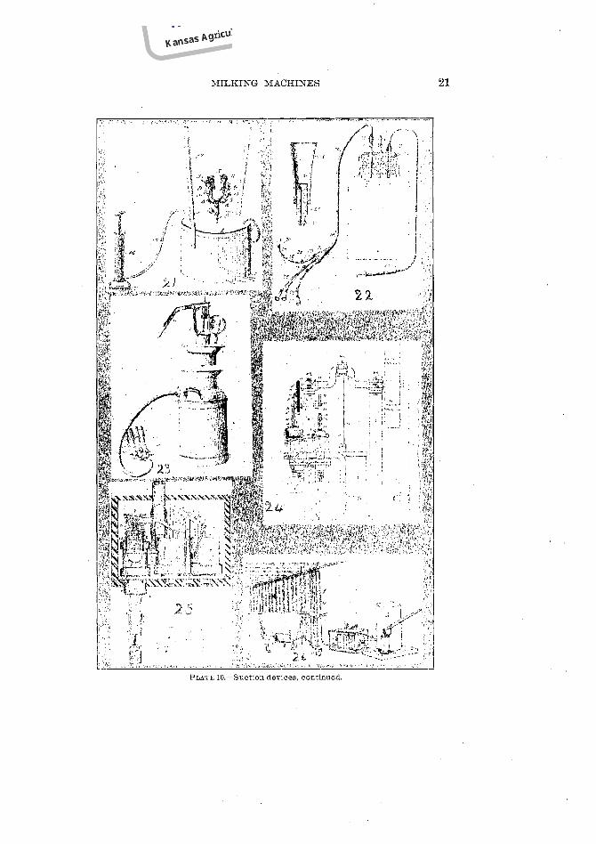

internal diameter conforming to the teat of the cow and a gauge diaphragm disposed within the cup adjustable to normally engage the tip of the teat and limit its downward movement. An endwise adjustable tubular plug screws into the closed end of the cup, one end of which forms the teat stop, the other having a nipple for at- tachment to the conduit. The milk receptacle has a common hand suction pump attached to it for creating the vacuum. See Plate 10.
No. 23, made by Walter Thatcher and Nathan Hussey, of Oska- loosa, Ia., in 1898, consists of a can having a stop cock, suction pump, vacuum gauge, and tube connected to the lid of the can which is easily removed to adjust to different cans. The teat cups, which are attached to the tube in the lid, have an inner teat receiv- ing section in whose lower part is a transparent tube and an outer section fitting over the inner casing and adjustable beyond the teat- receiving end thereof for engaging the udder of different animals. A pneumatic ring fastens the outer section in its adjusted position. See Plate 10.
No. 24, patented by Alex. Shiels, of Glasgow, Scotland, in 1895, is a combination of a vacuum reservoir and teat cups, together with pipe connections between the cups and reservoir, a pulsating valve arranged in the pipe connections with means for opening and closing it, and an automatic diaphragm valve located in a by-pass pipe arranged to open and supply vacuum to the cups when the pulsator valve is closed and the vacuum becomes reduced below the minimum. This diaphragm valve will also destroy the vacuum at the teat cups if it rises above the maximum. See Plate 10.
No. 25, invented also by Shiels the following year, has the pul- sating device, vacuum producer, pipe connections and a, vacuum motor connected with the supply pipe, which comprises two cyl- inders with their pistons, a piston valve for alternately admitting vacuum to each of the cylinders. A toothed fork is connected with the valve for operating the same, a rocking shaft being con- nected to the cylinder and pulsating device. This machin-e also has the vacuum-destroying valve. See Plate 10.
No. 26, made by Francis Devore, of Thompson, Iowa, in 1902, consists of a milk receiver, air exhaust pump, collapsible tension regulated chamber between the receiver and pump, and a casing in which the collapsible chamber is located. Springs connect the ends of the casing with the ends of the chamber and tend to dis- tend the latter. Telescoping tubes are within the chamber, the smaller being secured to one end and having perforations in its body, the larger passing through the other end and having perfor- ations outside the chamber, its outer end closed with a sliding plug


valve adapted to be pushed outward by the smaller tube when the chamber collapses. See Plate 10.
No. 27, another Devore machine, is similar to the above except the vacuum regulator consists of an air chamber having a perfora- ted body and cap with a valve adapted to close the openings in the latter, means for adjustably regulating the tension on the valve, suitable tubular connections between the chamber and milk con- duit. See Plate 11.
No. 28, patented by Fred West, of Browning, Wis., in 1901, is a closed milk pail upon the lid of which is attached in a horixontal position a small suction pump. The teat clamps have the body portion bent to a cylindrical contour, having one edge formed with openings, arms on the opposite edges adapted to be inserted through these openings and then bent upon themselves, whereby the clamp is fastened to the tube. Upward extending spring arms embrace the teat and are connected by a central tube to the pump and milk pail. See Plate 11.
No. 29, made by Alex. Gillies, Terang, Victoria, Australia, in 1903, is a pneumatic milk apparatus, the teat cup having a rigid casing and flexible lining, a cap connected to the lower end of the lining and provided with an opening in combination with a ferrule connected to the rigid casing for the admission of the pulsations between the lining and casing. A pulsator communicates with the ferrule and milk receptacle and opening in the cap. See Plate 11. . No. 30, patented by John Hulbert and Ira Park, of Holland Patent, N. Y., in 1902, is a milk machine with a teat receiver hav- ing an inflatable lining and separate sections with independent parts opening into the several sections. A valve controls the parts to open them to receive compressed air and to exhaust them, and a spring operates the valve in one direction, com- ,
pressed air forcing it the other way. A suitable mechanism con- trols the supply of fresh air to the pulsator. See Plate 11.
No. 31 is the first machine made by Wm. Lawrence, of Pollok- shields, Scotland, in 1897. It is a combination of two cisterns al- ternately filled with water, which decends from each through a pipe whose length corresponds to the strength of maximum suc- tion desired. An automatic distributing valve, with float at- tached, is stationed in one of the cisterns. There is also a min- imum suction reservoir which has a suitably loaded valve in combination with a branch pipe from the maximum suction pipe controlled by a valve. A flexible diaphragm upon the valve is operated by atmospheric pressure. The pulsator consists of a


cylinder having a double ended or elongated piston, provided with valve recesses controlling these parts, one communicating with the teat cups, another with the maximum milk receptacle, and a third with the maximum suction pipe. See Plate 11.
No. 32, patented in 1902 by Wm. Lawrence and Robert Kennedy, of Glasgow, Scotland, consists of a milk receptacle which has a pulsator on the cover, a vacuum regulating device, suction produc- ing apparatus, and a vacuum reservoir attached between the suc- .tion apparatus and vacuum regulator, and another between the vacuum regulator and pulsator. An inspection glass in the cover
is connected with the milk conduit from the teat cups. The cups have an outer flexible sleeve, over which a removable sleeve of sim- ilar material fits and which has an inner conical downwardly pro- jecting portion to embrace the teat and permit the independent collapse of the outer sleeve. The discharge nozzle on the opposite end of the outer sleeve is constructed to prevent the teat from blocking the discharge outlet. See Plate 12.
No. 33 is the Amos Gerhard machine, made at Clayton, Pa., in 1904. The milk receptacle has a false bottom through which a valve regulating the pipes leads. A bellows is fastened to the false bottom. A suction regulating branching pipe leads from the valve pipe, a collar is mounted upon the former from which a spring arm projects that holds a plate regulating the ingress of air at the end of the branch pipe, to which are also attached tlle suc- tion teat cups. See Plate 12.
No. 34, patented by David Sharples, of West Chester, Pa., in 1902,

I
is an apparatus for simultaneously applying suction to the teats and subjecting them to a pneumatic pulsating action varying in- versely with the volume of the milk flow between the fixed mini- mum and fixed maximum of intensity. The teat cups are of ob- long cross section, with opposite flattened wall portions of stiff construction; flexible portions connect the edges of the stiff parts. The mouth section is reduced and flexible. The second teat cup has an oblong fiexible walled mouth part and a distortable body portion, with stiff sides also of normally oblong cross section
whereby the oblong mouth may be pressed into approximately circular form. See Plate 12.
No. 35 is a milker patented by F. O. A. Weber, Cleveland, Ohio. This is a suction machine and the improvement consists of an ap- paratus constructed and arranged to draw milk from the teats of one or more cows by suction and to force said milk when drawn into a suitable vessel.
Hussey, of Mount Pleasant, Ohio, February 19, 1904. The object of this invention was to secure a simple, cheap and easily op- erated apparatus that should enable a number of cows to be milked simultaneously, and both thoroughly and rapidly, without annoyance or injury to the cow. An attachment (see drawing, letter AA) designated by two posts or uprights that are erected especially for the purpose, or forming part of the structure of the cow stable, to which is attached a horizontal pipe (B) of such
No. 36 is a milker patented by Nathan A. Hussey and Asa hel H.

length as to extend over a space occupied by a number of cows standing side by side a suitable distance apart. The claim of this inventor is that it is necessary that an impartation of an up- and-down motion of the nipples be secured so as to produce an ac-
I Y" . 375
tion on the teats similar to that given by the hand pressing or the pushing of a calf in nursing, this being of material assistance and resulting in a full and freer flow of milk than would otherwise be obtained. To produce this motion a rock shaft ( M ) is journaled over head, being provided with a number of radial bars ( M ) equal to the number of cows, on which depends a chain (N) whose lower

end is connected with a nipple carrying tubes as shown. A cam (O) on a shaft (P)journaled at right angles to the shaft ( M ) en- gages the upper side of the radial bar (Q) on shaft ( M ) and oper- ates to rock the latter, to lift the chains ( N ) while a weight (R) supplements the weight of the chain, causing them to lower. Shaft (P) may be revolved by any suitable means, but it can be conveniently driven from the pump shaft ( S ) by a belt running
from a pulley on the latter to a pulley on said shaft (P). The chains are also useful in preventing the nipples from reaching the floor, should they fall, and thus avoiding the possibility of dirt being sucked in.
No. 37 is a milking machine invented by Mark Mason Condron, of Marshfield, Ore. In this machine suction or vacuum is estab-
, lished to cause the milk to be drawn from the cow's teats, and the object of the construction is to provide a cheap and easily operated apparatus for milking two or more cows thoroughly and rapidly without injury to the animal. Also, with a more natural and less forcible operation, and also having means for automatically regu-
lating the pressure or suction force and to utilize a prime gener- ator of the 1atter by a simple adjustment of the parts for thor- oughly cleansing the apparatus by the use of water, and thereby always maintaining the same in a pure, sweet condition, ready for immediate use.
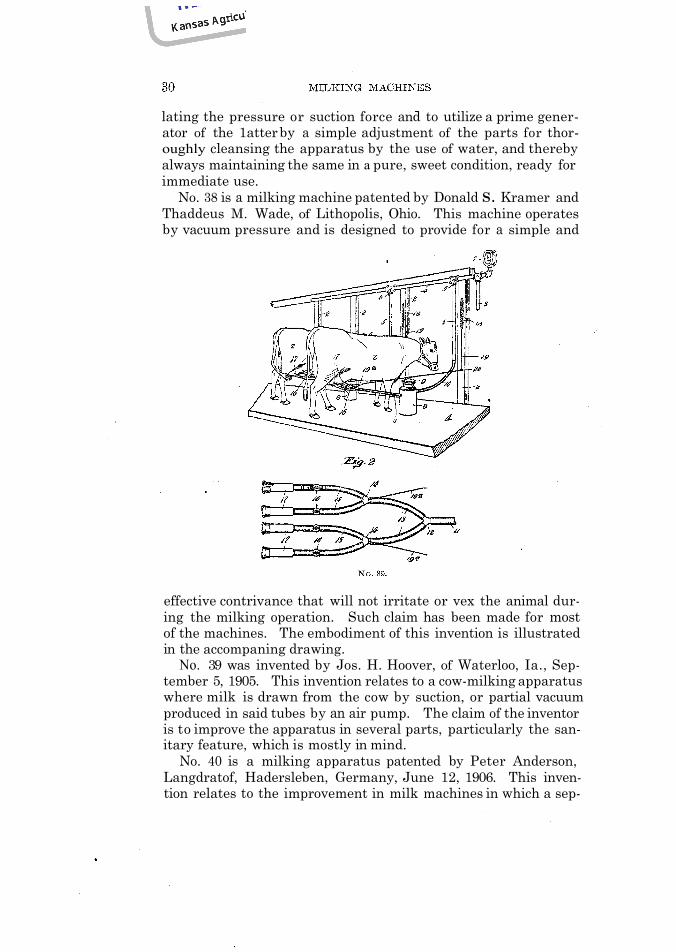
No. 38 is a milking machine patented by Donald S. Kramer and Thaddeus M. Wade, of Lithopolis, Ohio. This machine operates by vacuum pressure and is designed to provide for a simple and
effective contrivance that will not irritate or vex the animal dur- ing the milking operation. Such claim has been made for most of the machines. The embodiment of this invention is illustrated in the accompaning drawing.
No. 39 was invented by Jos. H. Hoover, of Waterloo, Ia., Sep- tember 5, 1905. This invention relates to a cow-milking apparatus where milk is drawn from the cow by suction, or partial vacuum produced in said tubes by an air pump. The claim of the inventor is to improve the apparatus in several parts, particularly the san- itary feature, which is mostly in mind.
No. 40 is a milking apparatus patented by Peter Anderson, Langdratof, Hadersleben, Germany, June 12, 1906. This inven- tion relates to the improvement in milk machines in which a sep-


arate and independent pump is provided to extract the milk from the cow or other animals operated upon. The details of the machine are shown by the accompaning drawing.
No. 41 is a milker patented by Loomis Burrell, of the D. H. Burrell Manufacturing Company, Little Falls, N. Y., and is an im- provement of the Burrell-Lawrence-Kennedy machine which is
now in operation at the Dairy Department of this Station. He took the patent out on this machine May 23, 1905. The intermittent or pulsating apparatus is applied to the teat cups by a portable mechanism which is connected with the exhaust milk receiving vessel. This is operated by a mechanism from a driving shaft in the barn, and in which the mechanical mechanism is of such con- struction that the pulsating mechanism can readily be connected with the driving shaft when the milk vessel has been placed in the desired position for milking. Special milk tubes, as shown in the drawing, are provided with this machine.
No. 42 is another machine invented by Mr. Loomis Burrell, of Little Falls, N. Y., in which the intermittent pulsations are pro-

duced by a special apparatus operated by a vacuum instead of a shaft, as in the previous machine, using the same teat cups as No. 41. This is the nearest approach t o the Burrell-Lawrence-Ken- nedy machine.

Milking Machines in Operation in the Dairy Department of the Kansas Experiment Station
The Burrell-Lawrence-Kennedey machine was the first suc- cessful machine that was put in operation by the Dairy Depart- ment. It consists of a vacuum pump, No. 43, which is operated by some power which exhausts the air from a system of pipe ex- tending from the pump into the milking stable. Along this sys-
tem there are one or more cylinders known as vacuum tanks, Fig. 44, which regulate to a certain extent the vacuum in the pipe sys- tem. Hence, in the case of admitting an unusual supply of air into the vacuum system during the time the teat cups are being attached to the cows, these chambers will provide for the sudden income of air without reducing the vacuum pressure materially. In this system there is a safety valve, also shown in No. 44, which regulates the extent of the vacuum beyond that which is required for milking. A gauge, No. 44, is also placed in this system, which indicates the number of inches of vacuum in the system to insure perfect operation. To this system are attached, by means of rub- ber hose, the milkers, No. 45, which consist of a pail or vacuum chamber, on top of which is an apparatus known as the pulsator, No. 46. To this pulsator are attached two rubber hose and a
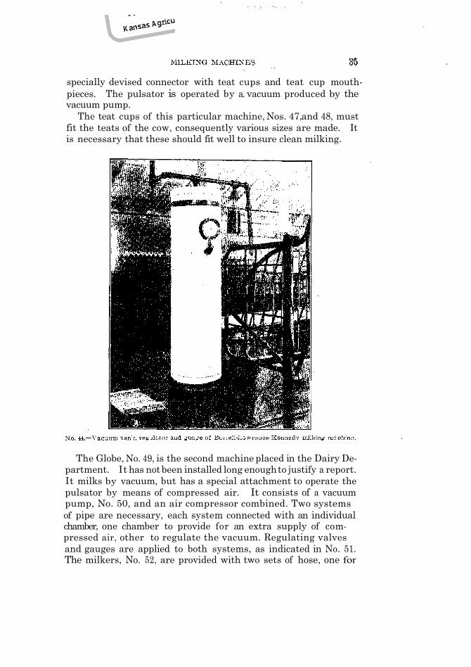
specially devised connector with teat cups and teat cup mouth-pieces. The pulsator is operated by a. vacuum produced by the vacuum pump.
The teat cups of this particular machine, Nos. 47, and 48, must fit the teats of the cow, consequently various sizes are made. It is necessary that these should fit well to insure clean milking.
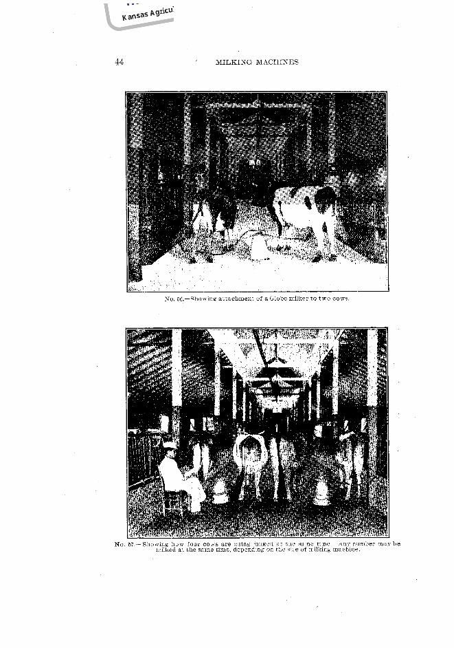
The Globe, No. 49, is the second machine placed in the Dairy De- partment. It has not been installed long enough to justify a report. It milks by vacuum, but has a special attachment to operate the pulsator by means of compressed air. It consists of a vacuum pump, No. 50, and an air compressor combined. Two systems of pipe are necessary, each system connected with an individual chamber, one chamber to provide for an extra supply of com- pressed air, other to regulate the vacuum. Regulating valves and gauges are applied to both systems, as indicated in No. 51. The milkers, No. 52, are provided with two sets of hose, one for


The Mehring milking machine has been improved and has just recently been put on the market in the West. (Ref. to No. 12, suction.) Nos. 57 and 58.
DETAILED PRINCIPLES OF MILKING MACHINES
Vacuum.-Vacuum is empty space. The atmospheric pressure at sea level is approximately 15 pounds per square inch. If a a vacuum is produced in a pail there are 15 pounds of pressure
exerted to every square inch of outside surface. Ordinarily the atmospheric pressure is read in inches. The pressure of the air sustains a column of mercury 30 inches high, or a column of water 34 feet high. Take a strong glass tube about three feet long, close one end, fill it with mercury in order to remove all the air, and invert it in a cup containing the same liquid. The mercury will sink to the height of about 30 inches, depending somewhat upon the atmospheric pressure. The weight of the column of mercury is equal to the downward pressure, which is 15 pounds, hence the same is balanced. Therefore, a rise of one inch of mercury in- dicates approximately one-half pound pressure.

Vacuum gauges are graduated to 30 inches, hence if the gauge is to register 16 inches as the proper vacuum for milking, it means that 8 pounds of pressure are applied to each square inch of the udder surface, which forces the milk out of the udder into the teat cups.
A vacuum may be produced in various ways: First, by means of a vacuum pump; second, by means of a steam-jet air exhauster;
NO 50 A Globe compressor I.... vacuum pu
third by means of a water vacuum pump. The most practical is a mechanically operated vacuum pump which is constructed in the same manner as a water lift pump, provided with a cylinder, plunger and valves, the latter being attached to a crank to pro- duce the up and down motion. This is probably the most efficient way of producing a vacuum under average farm conditions. This pump may be operated by means of a gasoline engine, a steam engine, electric motor, tread power, No. 59, or horse-power. Some inquiries have been made as to the practicability of operat- ing these machines with wind power. This seems to be impracti- cable on account of the uncertainty of such power, for the same is

needed at milking time every night and morning. A steam-Jet air exhauster is practicable only where the same can be applied close to a high-pressure steam-boiler, so that little condensation of the steam can take place in the high-pressure steam-pipe. Boilers are frequently used on dairy farms for the purpose of sterilizing or heating water. Where such conditions exist it would be practica- ble to use the steam for producing a vacuum, either by allowing it
to escape into a condensing system for the purpose of heating the water, or allowing the exhaust steam to enter a sterilizing oven which should be constructed in such. a way that there is no back pressure. The steam-jet air exhauster is efficient, extremely simple, and reliable. The chief objection is that it is apt to cause irregularity in milking if the operator is careless in letting the steam pressure go dow during the latter part of the milking period, or it may be too high at times. It is also objectionable from another standpoint, in that it is necessary to generate steam in the morning before the cows can be milked. Hence, one man is obliged to arise earlier to attend to thestarting of a fire.


The third, or water pump vacuum principle, operates o n the same principle as the steam jet. In this case a stream of water flows past the opening at a high rate of speed and creates a vacuum,but this principle can be applied only where there is an abundance of water at a high pressure.
POWER REQUIRED
The power required to operate a vacuum pump can be safely estimated at the rate of one mechanical horse-power to each
milker. For two cows two horse-power is required. However, this is greatly reduced as the number of milkers is increased, as for instance a five horse-power engine can safely operate seven milkers.
THE PLAN OF PIPE SYSTEM
The arrangement of the pipe system for milking machines which work by vacuum or by vacuum and pressure combined must be made to suit the conditions as they exist on individual farms, but the system which is the least expensive and probably has the greatest efficiency should of course be installed. The nearer the vacuum pump can be placed to the cows' stalls, the

, less friction there will be in the pipe, and correspondingly less power will be needed, No. 60. However, the only power that is safe to place near cows in any barn where there is hay is a tread power or a sweep horse-power, tread power being by all means the best of the two. By the use of a bull tread power the cost of milking can be reduced to a minimum, for a bull always needs
exercise and his surplus energy can be made use of in this way. The noise produced by the average tread power, however, is objec- tionable for the reason that it annoys the cows, hence such a power should be placed in a separate room partitioned from the regular cow stable. The next best plan is to have a room close to the milking stalls, as is illustrated in the drawing of the College barn, plan No. 1, which shows the pipe system of both the Bur- rell-Lawrence-Kennedy and Globe milking machines. In this plan, if the room be tightly partitioned, a gasoline engine with exhaust pipe running to the outside can also be placed here to


operate the vacuum pump. If not permissible, a small engine room may be built a short distance away from the stable so as to comply with the laws of the insurance company. A pipe leading from the vacuum pump of the engine room to the pipe system of
the barn may be laid underground, as shown in plan No. 2 and 3. . In places where there are small creameries or dairies, it is con-
venient to place the vacuum pump near the engine in a separate room from the churn and separator and connect the same with the pipe system in the stable. This is illustrated in plan No. 4. In some instances it would be convenient to place the vacuum pump

in the house where the gasoline engine is located for the purpose of pumping water and lighting the residence. The pipe system can be conveniently arranged to suit any condition that exists on the average farm. The arrangement that applies to the vacuum ,
pipe also applies to the compression pipe where the Globe ma- chine is used. Plan No. 5.
THE LOCATION OF THE PIPE IN THE STABLE
Probably the most satisfactory arrangement for milking ma- chines is the old-fashioned rigid stanchion: and it is advisable to use this where the covered yard stabling plan has been adopted, as shown in plan No. 6. In this plan the cows are placed in the stanchions during the time they are being milked, and at all other times they are in a covered yard, where they are comfortably stabled and fed their roughage. When cows are stabled for the night and a part of the day in these rigid stanchions it is not as


satisfactory as the swinging stanchion, or a stall with a partition, the latter being the most comfortable for the cow.
Where the stanchions are used the best location for the vacuum pipe is close to the stanchions, as indicated in plans 1, 3 and 4, but where cows are put in stalls, such as the Drown or Bidwell, or with partitions, it is quite inconvenient to locate the milker between the cows. For this arrangement we advise placing the milker behind the cows, hence the vacuum pipe should be placed on the stall back of the cows, as shown in plan No. 5.
In large dairies where manure carriers are used, it is conven- ient to have a special contr vance to reduce the labor. A ten-gal- lon can may be suspended from the carrier above, No. 61, and the milking can be done directly into the can by placing the pulsator on a specially constructed lid which fits standard ten-gallon cans.
A record of the weight of milk from the cows can be ob- tained by rolling up the cord on which the scale is suspended un- til the two outer cords are loose. The reading of the total weight of milk can then be taken, and by subtracting it from the milk that has been milked into this can previously, the difference will be the amount given by the two cows last milked.
SIZE OF PIPE
Due regard must be taken in selecting the proper size of pipe, for it is very important to have sufficient capacity of vacuum to pro- vide for the air that is admitted to the system while connecting the milker and attaching the teat cups to the cow without lowering the pressure materially.
The stall pipe in all cases should not be less than one inch in diameter, and it is advisable to have it even larger. This is espec- ialy necessary where a number of milkers are operated with the same system. The pipe leading from the stall pipe to the vacuum pump should be at least one and one-fourth inches in diameter. However, this depends somewhat upon the distance. If the dis- tance from the stable to the vacuum pump is more than one hundred feet, one and one-half inch pipe should be used.
Where the Globe milking machine is used the same size vacuum pipes are necessary as in the Burrell machine. However, in this case a compression pipe is also necessary in connection with the vacuum pipe. The compression pipe need seldom be larger than one-half inch, but where three or more machines are operated three-fourth inch pipe is necessary.
ARRANGEMENT OF COMPRESSION AND VACUUM PIPER WITH EFER- ENCE TO FREEZING
While milking there arises from the milk a vapor which in the winter time condenses in the vacuum pipe, freezes and finally clogs the pipe, and in the case of the compression pipe, where such is used, the air being compressed it liberates a part of the moisture and deposits the same in the pipe, which ultimately tends to clog it the same as the vacuum pipe. In both cases wherever there is a trap or a space for water to lodge in the system a pet cock should be placed at the lowest point in order to drain the moisture. All pipes should be laid in such a manner that they will slope to a low point so that they can be easily drained. Due caution should be taken in regard to this matter, for this may seriously handicap the perfect operation of the vacuum pump.
PAINTING THE PIPE
It is very important to have the outside of the vacuum pipe painted, not only for the preservation of the iron, but to make the system air tight. In erecting such a pipe system all joints must fit perfectly and if a joint sealer is used, such as white lead, it is necessary to see that none of it is placed inside of the fitting, as is generally done in steam and water plumbing. For vacuum piping the white or red lead should be used only on the threads which screw in the fitting, the pressure being from the outside instead of from the inside. The paints used for painting the system should be a heavy viscous paint like asphaltum or deodorized pitch. Both have given excellent satisfaction in preventing leak- age in the vacuum system.
VACUUM TANK
One or more vacuum tanks, depending upon the number of milkers used, should be placed in the system. As has been stated before,. the vacuum tank regulates the vacuum, for when there is an extra large amount of air admitted into the vacuum system through some accident, as for instance during the time the teat cups are being adjusted to the cow, this extra amount; of air must be provided without any rnarked decrease of vacuum pressure. The chamber should be at least large enough to allow seven cubic feet of vacuum. It is preferable to have more, for it will provide for a more uniform suction. In the Globe machine, where the compression system in connection with the vacuum is used, a similar tank should be placed, but in this case only two cubic feet of air space is necessary.

SAFETY VALVE
A safety valve should be placed in the system to prevent too great a vacuum. While the tank more or less provides for the immediate reduction of pressure, the safety valve provides for the increased pressure.
VACUUM GAUGE
A vacuum gauge should be placed in the system to indicate the pressure in case the vacuum pump or the safety valve does not act properly. The trouble can be easily discovered.
PRACTICABILITY OF MILKING MACHINES
The success of a milking machine is determined by the follow-
1. The reduction in the number of milkers or in the cost of
2. The elimination of hand milking, necessarily a laborious task. 3. The maintenance of both the quantity and the quality of the
4. Clean milking that must be done. 5. The possibility of using such a machine for the average cow. 6. The dependence that may be placed on a milking machine. 7. The possibility of securing returns commensurate with the
capital invested. First, labor.-The labor saved under practical conditions has
been conservatively estimated to range from 80 to 40 per cent. Hence, more responsible men can be employed and higher wages can be paid.
At intervals for a limited time careful comparisons were made between hand milking and milking by machinery, the Burrell- Lawrence-Kennedy milking machine being used. The cows, seven- teen in number, belonged to the College herd, their feed and at- tention being similar both before the machine was applied and while it was being used. In making this comparison the time re- quired to milk a cow, including variations caused by pulsations of the machine or hand strokes of the man, the number of pounds of milk drawn per minute and the effect upon the cow and the clean- ness of the milk were noticed. The first set of data was taken from cows milked by hand, three men milking different cows.
ing factors :
labor.
milk.

or 1.05 pounds of milk were drawn per minute. For the three men the average number of strokes was 106.6,
time to milk a cow 9.14 minutes, pounds of milk 12, or an average of 1.27 pounds per minute.
The best individual time was made by milker No. 1 on cow 16, a Jersey, the average of three milkings being 1.7 pounds per minute. The slowest time was made by the last man when milk- ing cow No. 10, only .71 pounds being drawn per minute, which was almost the identical rate of No. 2 while milking the same cow, but not more than one-half as fast as No. 1.


ute. In one minute the machine will milk 1.03 pounds more than a man milking by hand, and if weighing and sampling were elim- inated one man could conveniently tend to three milkers, thus drawing 5.63 pounds more than by hand. Hence, three machines are better than five milkers. While this comparison is calculated from the data of our experiments, we have, however, not esti- mated the increased time required to put the machine in opera- tion, to transfer the milkers from one cow to another, to attach the teat cups, to wash the machine and take are of the engine, which would decrease the per cent of labor economy to the extent as stated above.
Second.-By the use, of a milking machine the objectionable part of hand milking is greatly eliminated. The uncomfortable part of milking is the position in which the milker must place him- self. The continuous opening and closing of the fingers becomes tiresome. In the summer time it is exceedingly warm work and in winter it is cold, and in fly-time it is very disagreeable. By the use of the machine all of these objectionable features are elim- inated.
Third.-To determine whether the quantity and quality of milk from the average cow are maintained requires at least several years of experimental work. However, enough experimental work has been done to prove that no great decrease can come about. From the results so far obtained the quantity of milk from some cows has been reduced, while from others it has been increased. The quality is affected in practically the same way, hence, under average conditions, as far as has been experienced, the machine proves to be as efficient as the average milker milking by hand.
From a series of thirty-two tests to compare the thoroughness of milking it was found that the average cow milked by a machine is milked slightly cleaner than by average hand milking. Some- times cows get into the habit of holding up their milk. This is es- pecially true when the cow is first milked with a machine. Hence, it requires close observation at first to allow the machine to milk for a longer time and at the same time manipulate the ud- der until the cow adapts herself to the machine. The manipula- tion of the udder is quite essential in milking with the machine, more so than with hand milking, for with hand milking the udder is manipulated to a certain degree.
The process of manipulation consists of pressing the base of the udder from all sides by placing the hands on each side of the
\

udder. The pressure should be applied gently, with no more force than the cow can comfortably stand.
Fourth.-Machine milking is cleaner than hand milking. Twelve experiments were conducted in which duplicate samples of milk were taken. One set was taken from milk which was milked by hand and a second from milk that was milked by a ma- chine. These samples were set at a temperature of about 60° F., under the same conditions, and in all cases the milk taken from the milking machine remained sweet for a longer time, varying from one hour to ten hours longer than that obtained by hand milking. Similar samples kept at a temperature of 32° proved that the machine-drawn milk remained sweet from six to thirty- eight hours longer than hand-drawn milk.
The following table shows the number of bacteria per cubic centimeter in milk taken from a machine as compared with the number in milk drawn by hand:
These tests indicate the superiority in cleanliness of a milking machine over the hand method.
Great care should be taken to wash the teats of the cow thor- oughly before attaching the teat cups in order to secure good re- sults. The milking machine is comparatively easy to wash. Aside from the receptacle, the additional parts are the pulsator, the rubber tubes and the teat cups. The rubber tubes and teat cups can be easily cleaned as follows:
Before the milk has a chance to dry on the cups and tubes the machine should be connected as for milking and cold water fol- lowed with warm water should be drawn through the tubes, rinsing all passages through which the milk flows. Empty the rinse water, duplicate the operation by drawing the hot water with some alkaline solution such as salsoda or a small amount of caustic soda. This will remove the fat from the tubes, which is injurious to rubber. After washing each part of the pulsator with a brush and rinsing in boiling water it may be placed away to dry. The teat cups and rubber tubes should be placed in some antiseptic solution, which prevents decomposition and preserves the rubber.

Several tests as to the effectiveness and cheapness of different antiseptic materials were made, first with a saturated solution of boracic acid, second, a solution of lime, and third, a one per cent solution of formaldehyde. After soaking the rubber tubes and teat cups in these solutions they were thoroughly rinsed in boiling water and a sample of milk produced under the same condition was passed through each set. The milk was set away in a room at 70° temperature. The results were as follows: The milk passsed through rubber tubes laid in boracic acid solution became sour at the end of 48 hours; with lime solution at the end of 54hours; with the one per cent solation of formaldehyde at the end of 84 hours. This proves thee effectiveness of a formaldehyde solu- tion for sterilizing the teat cups and rubber tubes, but due care should be taken that these parts are carefully rinsed in boiling water before being used in connection with the milk. Boracic acid, though the most expensive and ineffective of the three methods of preservation, has one merit in that it preserves the tin. While a fomaldehyde solution is the most effective, lime is by all means the cheapest, and is probably the most practical where large yuan- tities of antiscptic materials are to be used.
Fifth.—While no definite degree of comfort or annoyance of an animal can be determined, it is an easy matter to notice whether a cow is in a distressed or a comfortable condition. From all observations that have been made at the Station in this connection, while under normal milking conditions, no cow has given any indication of uncomfortableness while being milked by a machine. In fact we have found that milking machines, if the vacuum is normal and the teat cups fit well, are more com- fortable to the cow than hand milking. Some cows can be milked by milking machines that as a rule cannot be milked by hand.
It is quite essential to take some precautions to see that the suction is not too great and the teat cup is not too large or too small for if a tent cup is too large the constant suction tends to expand the teat to practically the same size as that of the inner diameter of the cup. This causes a temporary swelling, which is somewhat annoying, at the same time giving chance for a consid- erable amount of milk to be retained in the teat whi1e in this dis- tended position. The cause of this temporary swelling is due to the increased amount of blood that is drawn into the teat. If this be practiced for a long the it will result in an undue distention of the teat and cause it to become sore. If the teat cups are too small it will interfere with the milking by obstructing the flow of milk and closing the milk duct of the teat.

During the summer months it has been found necessary to be especially careful in the use of teat cups and rubber mouth pieces. While cows on pasture are giving a large flow of milk the udder and teats are larger and more tender and often sunburn and chap so that it is advisable to use teat cups and mouth pieces that are a little larger than what have been used during the rest of the year so as not to injure the teats. In attaching the teat cups the teats are sometimes not squarely drawn into the teat cups. This fre- quently occurs when milkers are in haste. As a result the open- ing of the teast is drawn against the side of the cup and no milk can be drawn from the teat. This explains why by careless attach- ment of the teat cups sometimes you will find that one teat is not milked. For good and effective work, after the teat cups have been attached it is a wise plan to partially draw them down and allow the cup to place itself back in position. By doing this the opening will adjust itself to the teat cup. Sore and chapped teats are more quickly healed when milked with a milking machine than when milked by hand.
Sixth.-The reliability of a machine depends largely upon its simplicity. A machine must be simple and easy to operate if placed in the hands of the average milker. No serious difficulties have been encountered with the machines at this Station since the beginning of their operation. Breakages are liable to oc- cur with even the simplest mechanism, and every dairyman must be prepared for emergency. The milkers as a rule are du- plicated and it would be seldom that there would be more than one milker broken at a time. Each company should send out an extra supply of the most breakable material with each machine. There is little to be broken on the vacuum pump which cannot be readily repaired at an ordinary machine shop. The most es- sential part of a milidng machine is to have reliable power, for without power the milking cannot be done. In a large dairy it would be quite essential to be provided with two sources of power. In case there would be a failure to operate one machine the other could be readily attached. We would suggest in connection with a gasoline engine, a sweep power or a bull tread power, which can be bought at a nominal price, the latter being a practical machine for pumping water and other light work necessary in large dairies, or if a steam boiler is at hand it would be advisable to secure a steam air exhauster.
Seventh.-The question as to whether a machine insures a safe investment depends upon the number of cows that are to be milked, the class of cows on hand, and the ability of the operator

to run the machine successfully. For a small dairy the invest- ment in a complete outfit at the present price would not warrant interest on the money invested. However, there is another phase to be taken into consideration: the average man would rather operate the milking machine than do the milking by hand, which may off-set the actual interest on the investment. For dairies of fifty cows or more it becomes exceedingly profit- able. Aside from the real interest o n the investment it removes the disagreeable part of the work, reduces the labor and insures the proprietor a greater degree of certainty that his work will be accomplished. .
PULSATIONS AFFECTING THE EFFICIENCY OF MILKING
A great number of trials have been made in testing the effi- ciency of milking at various numbers of pulsations per minute. The pulsator was changed so that one machine gave an average of 61 strokes, while the other made 43. The slower speed gave the better results, for 63 of a pound more milk was drawn at 43 pul- sations than at 61, although the former was run 12 pulsations below the average as advised by the manufacturer. The best time was made at 41 pulsations, when 4.5 pounds of milk were drawn in one minute. When the pulsations fall below 40 the vacuum seems to be applied to the teat too long, and makes the cow feel slightly more uncomfortable, hence we think that with the Burrell- Lawrence Kennedy machine from 45 to 53 pulsations per minute will give the best results.
THE PROPER AMOUNT OF VACUUM
A number of tests have been made to determine the proper vacuum to be applied for milking. The vacuum was changed from 11 inches to 20 inches. At 11 inches the average test indicates that 1.77 pounds of milk were drawn per minute; at 16 inches pressure, 2.3; at 17 inches pressure, 2.4 ; at 20 inches pressure, 2.5. While milking under this strong vacuum the milk was re- moved at a slightly greater rate. It, however, proved to be more uncomfortable to the cow, and a decrease in the flow of milk was discovered. Approximately 16 to 17 pounds is the safest vacuum for milking.
FEEDING COWS DURING MILKING
It has been found especially desirable to feed cows concentrates during milking. This is especially true at first, for it has a tend- ency to distract the attention of the cow from the milking machine and seems to induce the milk secretion.

UNIFORMITY IN MILKING
It is absolutely necessary in order to secure good results to milk with a uniform vacuum and uniform pulsation and with the same teat cups. Frequent, changes in any of the above particu- lars will. influence the flow of milk.
ATTACHING TEAT CUPS
This should be done in such a may as to lose the least amount of air. Notice Nos. 62, 63, 64 and 65.
MILK DRAWN AT DIFFERENT PERIODS OF TIME
In this experiment the milk was weighed after the machine had been attached two minutes, and weighed at regular intervals of two minutes until all the milking was done. These experiments were to determine the approximate amount of milk drawn at the different periods of milking. The object of this was to estimate whether or not it was practical to use the milking machine at first and then follow it by hand stripping, but from the results ob- tained it proves that this is an impractical scheme, for the milking machine milks approximately at the same rate and ratio as the hand milker.
1NDIVIDUAL RECORDS
It is essential for experiment stations, and ever, for private dairymen, to know approximately the amount of milk given by each cow. The present milking machine, designed for milking two cows at one time and into the same receptacle, makes it quite impossible to determine with any degree of accuracy the amount of milk given by each cow. It is therefore quite essential that a scheme should be devised to improve this particular part of the machine. It has been suggested that cows should be milked by hand every week one day, or two consecutive clays every two weeks, in order to obtain these records. It has been our ex- perience that after the cows have once become accustomed to the milking machine they will not respond with any degree of accu- racy to hand milking, which of course will destroy the accuracy of the records. It is therefore essential to obtain these records from the cows when milked by the machine. It would seem also quite essential for large dairies to have one milker constructed so as to keep the milk separate for the purpose of obtaining records from their cows. It is fully realized that it is far more convenient to milk two cows in the same receptacle, but one special milker in a large dairy would not discommode the operators and would be extremely valuable in determining the value of the cows.
Mr. A. Miyawaki, a Japanese student in the Dairy Department,

Kansas Agricultural College, suggests the following improvement, on the Burrell-Lawrence-Kennedy machine, No. 66: He places the pulsator on a specially fitted cover provided with a heavy rub- ber ring. This is placed on a can with straight sides, in which are placed two half-round cans, the central plunger being extended and grooved so that the milk from each side is drawn into its par- ticular receptacle.
CONCLUSIONS
1.-- A milking machine will milk cows as thoroughly as the aver- age milker.
2.-Some cows give more milk when milked with a machine than when milked by hand; others give less.
3.- It is extremely necessary for the man in charge to fully understand how to operate a milking machine.
4.- To reach the highest degree of success cows should be se- lected and bred to respond to machine milking. If this factor is taken into consideration machine milking will be equally as suc- cessful as the best hand milking.