Embed Size (px)
Citation preview
Small Bridges Conference 2015 Saving Walton Bridge
AECOM 1
SAVING WALTON BRIDGE
John Hart, Technical Director, AECOM, Brisbane
Tom Dowling, Principal Engineer, AECOM, Newcastle-upon-Tyne
Michael Hughes, Senior Project Manager, Brisbane City Council
Abstract
Walton Bridge is a two span unreinforced concrete buried arch bridge. At 115 years it is one of the
oldest bridges in Brisbane and still carries an arterial road over Enoggera Creek. A previous
assessment had found the bridge to be cracked and lacking in structural capacity and its
replacement was recommended. This led to the imposition of a load limit and a reduction in the
speed limit.
Brisbane City Council commissioned a feasibility study to produce a range of options for both
refurbishment and replacement. AECOM took a different approach to the assessment, by analysing
the structure as a masonry arch with no tensile strength. This type of structure can carry
concentrated traffic loads by allowing the eccentricity of the line of thrust within the thickness of the
barrel of the arch. This analysis was undertaken with two specialist software packages, and led to
the conclusion that the strength of the arch is sufficient for unrestricted loading.
Meanwhile a monitoring program was instigated to measure displacements and crack widths to
manage the risk of progressive structural damage.
The refurbishment scheme comprised the construction of a rigid pavement with waterproofing,
installation of drainage systems to exclude water from the arch backfill, concrete patch repairs, and
crack injection. The refurbishment has been completed and the bridge is expected to have many
more years of life in service.
Figure 1 – Walton Bridge
Small Bridges Conference 2015 Saving Walton Bridge
AECOM 2
1.0 Background
1.1 Walton Bridge
Walton Bridge (Figure 1), an asset of Brisbane City Council, is a two span unreinforced concrete arch
bridge which carries Waterworks Road across Enoggera Creek at The Gap. The original bridge was
built in 1900 and major modifications were made to the structure in 2002 to address some
structural defects and add a cantilevered footpath structure on the northern side of the bridge. A
second two lane steel bridge was erected beside Walton Bridge at that time, such that Walton
Bridge now carries two lanes of city-bound traffic and the steel bridge carries two lanes of outward-
bound traffic. Walton Bridge is one of Brisbane’s oldest bridges and was added to Council’s
Heritage Register in 2004.
1.2 Previous Assessment
A detailed assessment in 2012 used a structural finite element model with shell elements. The arch
capacity was based on limiting the tensile stress from combined axial and bending effects to the
tensile strength of the concrete based on an assumed concrete strength. The effective depth of
the section was reduced in places where an inspection had found significant cracks. Some crack
widths were monitored and found to have increased slightly over a time interval of six months.
The finding was that the bridge had insufficient capacity for as-of-right semi-trailers, as well as other
vehicles requiring a permit to travel. A 20 tonne load limit and a 40 km/h speed limit were
implemented. The presence of four significant cracks was taken as indicative of a state of collapse
having been approached. The advice was to prop or externally reinforce the bridge within six
months and to replace it within five years.
1.3 Feasibility Study for Upgrade or Replacement
The state of Walton Bridge, as disclosed by the previous assessment, had resulted in an ongoing
asset management and risk management task for Council. The loading and speed restrictions were
unsatisfactory for an arterial road. Council invited proposals for a feasibility study to investigate
options to upgrade or replace the bridge. AECOM also offered to reassess the bridge using
analytical methods specific to buried arches and was engaged by Council for the study and
subsequently for the refurbishment design.
2.0 Initial Inspection and Monitoring
2.1 Inspection and Monitoring
In view of the concern over the capacity of the bridge, an initial inspection was undertaken to check
that the structure had not deteriorated noticeably since the previous inspection by others – which
was found to be the case.
Crack width gauges were installed across five cracks and twelve targets were established to
measure six dimensions between abutments, pier, and arch barrel.
The crack gauges were viewed and recorded with magnification from a telephoto camera. Crack
widths could be read to an accuracy of approximately 0.5 mm and the accuracy of hand-held laser
distance measurements was 1 mm to 2 mm. This monitoring could be undertaken without
interrupting traffic on the bridge, and the accuracy was sufficient to detect movements much
smaller than those which would be associated with serious structural distress.
Small Bridges Conference 2015 Saving Walton Bridge
AECOM 3
All the movements were very small or immeasurable and within the degree of accuracy of the
instrumentation. There was no indication that the bridge had experienced any change in crack
widths or key dimensions over the course of the monitoring.
2.2 Testing and Measurement
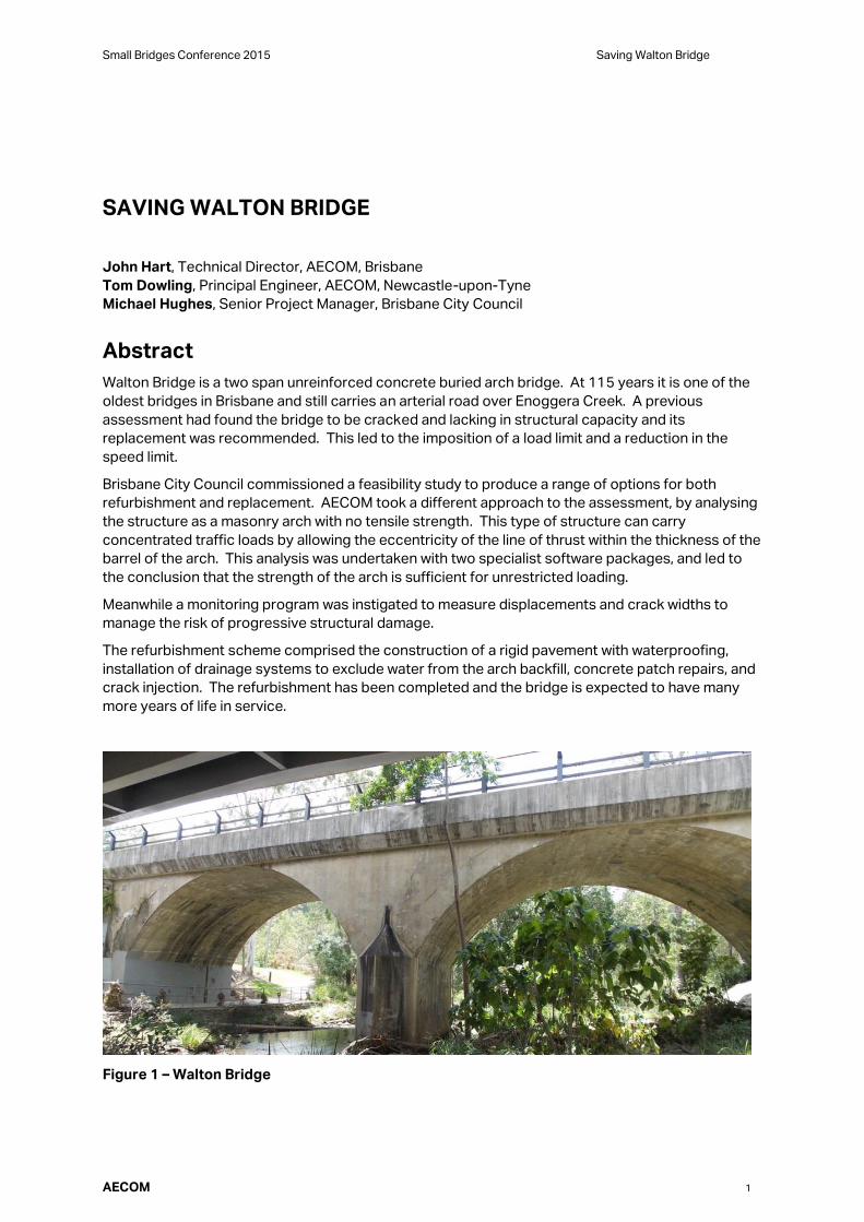
In arch analysis, the shape and thickness of the arch are critical. In the absence of drawings, the
data in Table 1 was obtained by hand measurements and this was considered suitable for a
feasibility study.
Table 1 Key Dimensions
Dimension Measurement
(mm)
Clear skew span 13820
Mid-span rise 4300
Quarter-span rise 3300
Arch thickness near crown 600
Arch thickness at abutment
springing 1200
Arch thickness at pier springing 1800
Pier thickness 2500
Backfill depth at crown 600
A rough estimate of concrete strength at six points was obtained by means of an impact hammer,
with ten readings at each point. Only four points had a sufficiently consistent set of readings to
qualify for use to either ASTM or Euronorm standards and together these indicated a 10th percentile
cylinder strength of 25 MPa. Given the variability and the inaccuracy of the test method, the
feasibility study assumed a concrete strength of 14 MPa, which is the Queensland Department of
Transport and Main Roads (TMR) default for unidentified concrete.
3.0 Behaviour and Analysis of Buried Arch Bridges
AECOM took a different approach to the assessment by adopting methods used more usually for
buried masonry arch bridges.
3.1 Fundamental Arch Behaviour
An arch carries loads predominantly and desirably in axial compression, and the smooth curve of
the arch is best suited to distributed loading. Concentrated loads, such as wheel loads, are
distributed to some extent through the fill above the arch but cause bending moment as well as axial
force in the arch.
Masonry arch bridges are conventionally assumed to have no tensile capacity in the joints between
the stones or bricks, and yet they can carry concentrated loads because the line of thrust in the
arch departs from the centroid of the cross section and becomes eccentric. It is not necessary for
the eccentricity to be limited to that which first causes tension on one face of the arch provided the
remaining area in compression has sufficient strength to carry the thrust.

Small Bridges Conference 2015 Saving Walton Bridge
AECOM 4
An unreinforced concrete arch can carry loads in the same fashion. While bending moments could
alternatively be sustained by the tensile capacity of the concrete, if a crack should occur, due to
high load or merely shrinkage, then the tensile strength vanishes across the width and depth of the
crack. The structural capacity is sensitive to the presence of existing cracks or the formation of
new ones. More confidence can be placed in an analysis which does not rely on concrete tensile
strength.
One reason given for concern about the safety of the bridge was that the several cracks observed in
the intrados of the arch barrel were indicative of the partial formation of four hinges, which would
lead to collapse of the bridge. However, those four hinges do not all cause cracking on the same
side of the arch. Therefore the existence of three or four cracks in the intrados is not necessarily a
sign that collapse is imminent.
An unreinforced concrete arch of this size is almost certain to have shrinkage cracks originating
soon after construction, and this is an alternative explanation of the observed cracks. While there
are no available historical records to verify the age of the cracks, there was anecdotal evidence that
cracking was present as far back as the late 1970s.
3.2 International Practice
There are few buried arch bridges in Australia and there are no particular provisions for them in the
Australian bridge design code, AS 5100.
Elsewhere, and particularly in Britain, there are very many buried arch bridges still in service. The UK
Highways Agency has issued several specifications and advisory guidelines in their Design Manual
for Roads and Bridges which cover the assessment and design of masonry arch bridges:
- BD21/01 The Assessment of Highway Bridges and Structures
- BA16/97 The Assessment of Highway Bridges and Structures (Advice Note)
- BD91/04 Unreinforced Masonry Arch Bridges.
It is not usual to analyse a buried concrete arch structure using conventional elastic methods
commonly applied to other types of structure. This is because this type of analysis does not handle
unreinforced concrete elements very well and the soil/structure interaction is too complicated. The
general approach would be to either use an empirical method or to use an industry recognised
specialist computer program to analyse the arch. In practical terms, there are two widely used
computer programs available which give an assessment of the collapse load of the arch namely
ArchieM and LimitState RING. Considerable research stands behind these programs including full-
scale testing and they have been widely used in the UK for many years.
3.3 Dynamic, Load, and Capacity Reduction Factors
In AS 5100, the dynamic load factor is given as a function of the relevant load – a single axle, an axle
group, or a design truck, although the factors are based on beam rather than arch bridges. The
factor diminishes as the depth of backfill increases. The dynamic factor was taken conservatively
as 1.4. The load factor for traffic is 2.0 for assessment vehicles and 1.8 for the current design
vehicle SM1600. The capacity reduction factor for plain concrete in compression is 0.6. Thus the
total combined factor between nominal load and characteristic strength for assessment vehicles
was conservatively 4.7.
Deadloads are distributed along the bridge evenly and do not cause any eccentricity in the thrust
line so are relieving for arch performance and therefore have a load factor of 0.85. Similarly
superimposed dead loads have a load factor of 0.7.
British practice uses different values for all these factors, and is generally less conservative.

Small Bridges Conference 2015 Saving Walton Bridge
AECOM 5
None of the codes or guides define the effect of traffic speed on the dynamic factor, at least not
until the speed becomes very slow (10 km/h in the Queensland TMR assessment brief). A review of
the literature was unproductive. Moreover, most of the research has been on beam bridges, where
there is a relationship with the natural frequency of the span. The buried arch would behave
differently. There is not a generally accepted quantitative link between vehicle speed and dynamic
factor. No reduction in dynamic factor has been made in this assessment, and therefore no speed
restriction is implied.
3.4 Modified MEXE
MEXE, the (British) Military Engineering Experimental Establishment, developed a semi-empirical
method for assessing the capacity of buried arch bridges for military purposes. The method has
been modified for general use in civil engineering, and calibrated for a 40/44 tonne British truck
having 20 tonne load on a double axle and 24 tonnes on a triple axle, both being more severe than
legal limits in Queensland. In this simplistic method a provisional axle load is determined based on
span, ring thickness, and depth of fill which is then modified by factors to account for arch profile,
shape, constituent material, condition, cracks, and arch deformation to derive the assessed
capacity,
Assessment of a masonry arch bridge to BD21/01 adopts the Modified MEXE method for the initial
analysis. More complex methods are undertaken if the arch parameters do not fit the
recommended range of parameters for Modified MEXE, or if it gives an inadequate capacity, or if
there is reason to believe that it is unconservative. It is known to yield unconservative results for
arches with crown fill depths greater than the arch barrel thickness.
The accepted view that Modified MEXE is a simple and conservative method has been challenged in
the literature, but this applies mainly to spans much shorter than at Walton Bridge.
3.5 Three-Pin Arch Method
A three-pin arch is a stable structure. If a fourth pin is formed, the structure becomes a mechanism
and collapses. The computer program ArchieM calculates the position, load, and size of the line of
compressive thrust within the physical boundaries of the arch ring and the abutment and pier
supports. This thrust line can be adjusted to find the most favourable outcome, considering the
loading at all points on the structure. In general, the line of thrust is eccentric and can thereby
transmit both compression and bending moment. The method ignores the tensile strength of the
arch. It is a two-dimensional model, for which the transverse distribution of load is taken from
BD21/01.
The analysis satisfies equilibrium and is a lower bound estimate of the arch capacity.
3.6 Four-Pin Arch Method
A four-pin arch is a mechanism on the point of collapse. This method is analogous to the plastic
design of steel frames. The method can be employed in practice through the computer program
Limitstate RING. It is an upper-bound method which uses optimisation algorithms to find the
collapse load.
RING idealises a bridge as a series of blocks. It disperses live loads through fill in accordance with
BD21/01 onto these blocks which are in contact but subject to crushing, sliding, and hinging. The
movement of the arch is restrained by its self weight and by backfill elements through passive
resistance. Unlike ArchieM the user has to identify the worst vehicle position by hand.
Small Bridges Conference 2015 Saving Walton Bridge
AECOM 6
4.0 Capacity Assessments
4.1 Assessment Vehicles
The basic assessment vehicle, as used in the previous investigation, was a 42.5 tonne gross mass
six axle semi-trailer. This vehicle has as-of-right access on Waterworks Road without permit. The
truck has a triple bogey carrying 20 tonnes and a double bogey carrying 16.5 tonnes.
Council further requested that the bridge be checked for SM1600 loads to AS5100.2 as well as two
Council bus configurations. The calculations were completed for a Volvo B7R bus with a peak single
axle load of 10 tonnes and a Volvo B12R bus with a double axle load of 14 tonnes.
4.2 Structure Configuration
The unreinforced concrete arch bridge comprises two skew spans of 13.82 m clear with a nominal
skew of 9°. The arch barrel dimensions are detailed in Table 1.
The bridge width is 8 m and has been widened to accommodate a cantilevering footway which is
assumed to be supported by the spandrel walls. The bridge supports two lanes of traffic so one
lane of traffic is assumed to be supported by an arch structure 4 m wide. There were no longitudinal
cracks in the intrados that would limit the width of distribution.
The bridge has approximately 600 mm of fill above the crest of the arch barrel and it is assumed to
be level across the structure. This 600 mm of fill includes road base and surfacing materials.
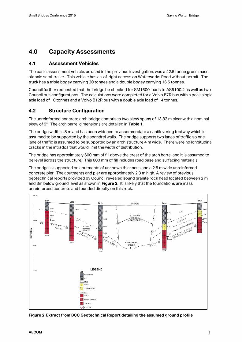
The bridge is supported on abutments of unknown thickness and a 2.5 m wide unreinforced
concrete pier. The abutments and pier are approximately 2.3 m high. A review of previous
geotechnical reports provided by Council revealed sound granite rock head located between 2 m
and 3m below ground level as shown in Figure 2. It is likely that the foundations are mass
unreinforced concrete and founded directly on this rock.
Figure 2 Extract from BCC Geotechnical Report detailing the assumed ground profile

Small Bridges Conference 2015 Saving Walton Bridge
AECOM 7
4.3 Modified MEXE
This method shows that the bridge can comfortably carry the full 40/44 tonne British assessment
vehicle and hence also the assessment vehicles described in Section 4.1.
As the method may be unconservative when the depth of fill at the crown is greater than the ring
thickness, the analysis was repeated with a nominal reduction in the depth of fill from 600 mm to
400 mm, in which case the capacity is still sufficient for the full 40 tonne truck.
As an extreme case, an analysis using a 400 mm thick arch ring thickness with 300 mm depth of fill
gave an allowable truck mass of 32 tonnes.
In UK Highways Agency practice, the Modified MEXE capacity takes precedence over alternative
methods, even if they give lower results “unless there is good reason to believe that it is
unconservative for the case in question, for example where the fill depth is greater than the arch
thickness”.
Nevertheless, it is prudent to consider an alternative method of analysis as well.
4.4 Three Pin Arch
A three pin arch analysis was undertaken using the program ArchieM. Using the measured
geometry, a number of analyses were conducted to explore:
- Various assessment vehicles – 42.5 tonne semi-trailer, 22.5 tonne rigid truck, two Council bus
configurations, and SM1600
- A range of concrete strengths – nominal 14 MPa and 12 MPa and 16 MPa
- Both Australian and UK dynamic load, and capacity reduction factors
- Single and dual lane loading (with the same vehicle in each lane)
- Two assumptions on pier height (to ground level and to assumed rock head).
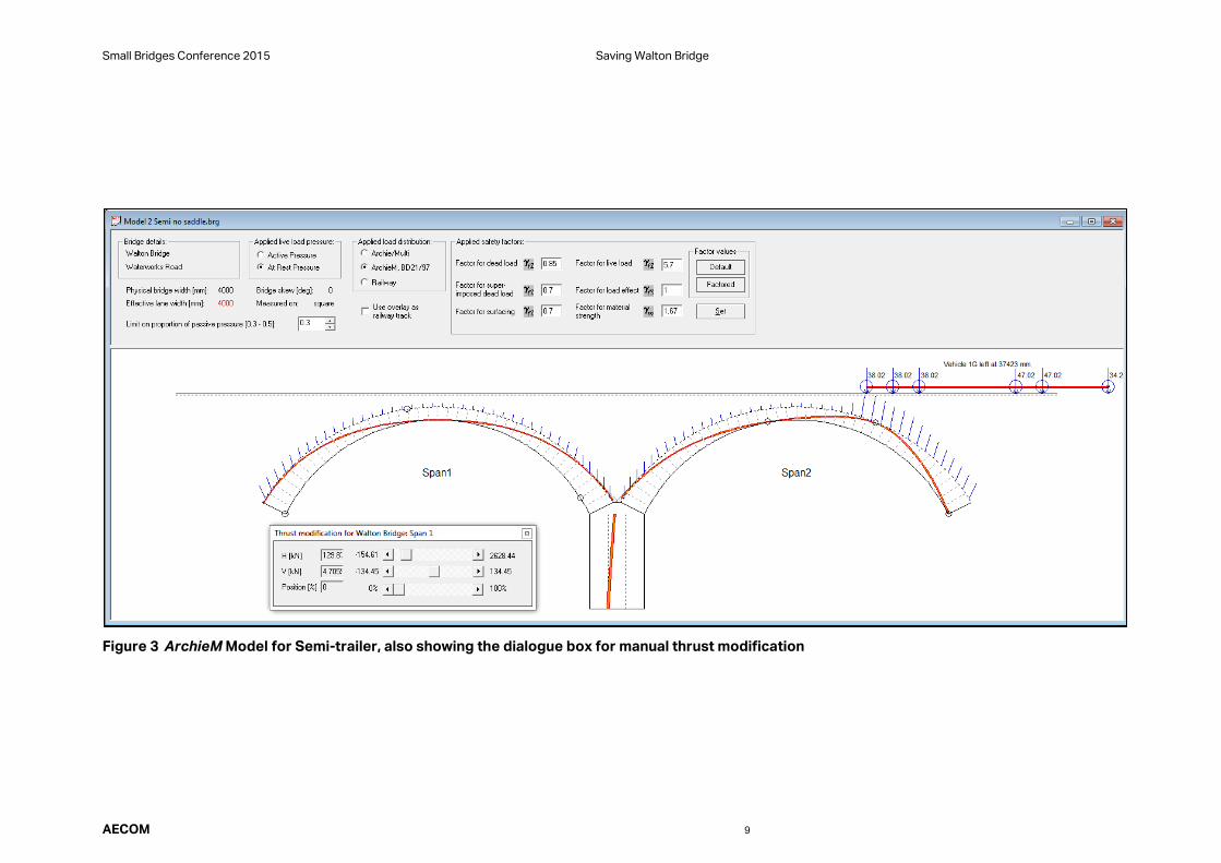
An excerpt from the ArchieM output in shown in Figure 3, and the results are summarised in Table 2
which gives the ratio of the available capacity to the vehicle loading at ULS. A ratio greater than 1.0
indicates spare capacity. All vehicles apart from SM1600 loads were found to be within the capacity
of the arch bridge.
Points to note:
- Capacities are less than those given by the Modified MEXE method.
- Capacities using UK load and capacity factors are about 10% higher than using Australian factors.
- Variation of concrete strength by 2 MPa affects capacity by less than 5%.
- Single lane capacities are 11% higher than for dual lane loading.
- No reduction has been made to the dynamic load allowance, therefore no speed restrictions are implicit.
4.5 Four-Pin Arch Method
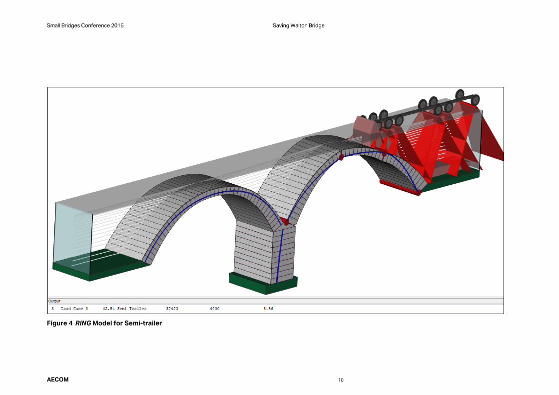
A four pin arch analysis was undertaken using the program RING. This program was used to check
the results of the three pin arch analysis.
The same assessment vehicles were used namely a 42.5 tonne semi-truck with or without its trailer,
22.5 tonne rigid truck, two Council bus configurations, and SM1600 vehicles.
The same assumptions and factors were used that were also used in the previous analysis.
An excerpt from the RING output file is shown in Figure 4. All the vehicles assessed were found to
be within the capacity of the bridge, refer to Table 2 for full results.
Small Bridges Conference 2015 Saving Walton Bridge
AECOM 8
In order to try to more closely replicate the results obtained from ArchieM a number of variables
were adjusted. Even by adjusting the concrete compressive strength and passive earth resistance
to minimal values the analysis still gave enough capacity in the arch to support the loads.
In the program there is an option to introduce areas of mortar loss between adjacent rigid blocks to
model a cracked arch. Although there was a drop in capacity even by introducing modest areas of
mortar loss at all four quarter points the structure was still showing adequate capacity for the
assessment vehicles.
It should be noted that in this assessment the passive earth resistance has been limited to 30% of
the normal passive resistance in line with British practice, as significant movement would be
required to mobilise full passive resistance.
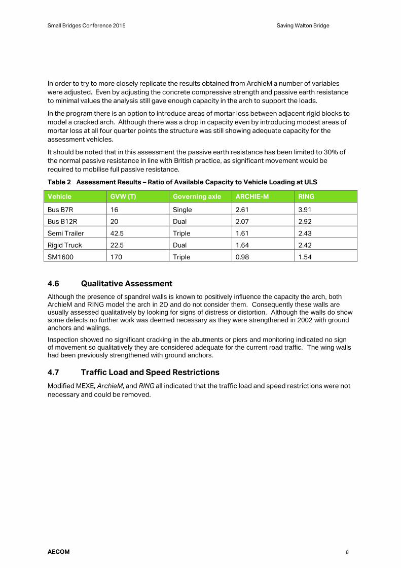
Table 2 Assessment Results – Ratio of Available Capacity to Vehicle Loading at ULS
Vehicle GVW (T) Governing axle ARCHIE-M RING
Bus B7R 16 Single 2.61 3.91
Bus B12R 20 Dual 2.07 2.92
Semi Trailer 42.5 Triple 1.61 2.43
Rigid Truck 22.5 Dual 1.64 2.42
SM1600 170 Triple 0.98 1.54
4.6 Qualitative Assessment
Although the presence of spandrel walls is known to positively influence the capacity the arch, both ArchieM and RING model the arch in 2D and do not consider them. Consequently these walls are usually assessed qualitatively by looking for signs of distress or distortion. Although the walls do show some defects no further work was deemed necessary as they were strengthened in 2002 with ground anchors and walings.
Inspection showed no significant cracking in the abutments or piers and monitoring indicated no sign of movement so qualitatively they are considered adequate for the current road traffic. The wing walls had been previously strengthened with ground anchors.
4.7 Traffic Load and Speed Restrictions
Modified MEXE, ArchieM, and RING all indicated that the traffic load and speed restrictions were not
necessary and could be removed.
Small Bridges Conference 2015 Saving Walton Bridge
AECOM 9
Figure 3 ArchieM Model for Semi-trailer, also showing the dialogue box for manual thrust modification
Small Bridges Conference 2015 Saving Walton Bridge
AECOM 10
Figure 4 RING Model for Semi-trailer
AECOM 11
4.8 Confirmation of Design Parameters
As the project moved from feasibility study to detailed design, it was appropriate to undertake
further site investigation including.
- Services searches and scans – to determine construction constraints
- Crack and defect mapping - sufficient for quantifying purposes.
- Topographic survey – including the arch profile. No major differences.
- Geotechnical Investigation. Three boreholes were completed to confirm soil properties for arch analysis
and pavement slab design. Fill properties used in the feasibility study were retained.
- Ground penetrating radar (GPR). GPR was used to confirm arch barrel thickness, to locate voids and to
confirm pavement thickness. Thickness was also confirmed using a pilot hole cored through the crown of
the arch. The bridge was scanned from the road surface and from beneath the arch. The instrument
under the arch was unable to penetrate fully through the arch ring to confirm its thickness at the springing
points and the GPR Survey provided typical details rather than a comprehensive survey. The significant
finding was that the minimum depth of fill at the crown of the arch was 430 mm rather than the 600 mm
used in the feasibility study.
- Concrete cores. Cores were collected from four points in the arch barrel. These samples were tested in a
NATA certified laboratory to determine compressive strength, for arch analysis. The strength used for the
reassessment was increased from 14 MPa to 19.5 MPa.
Reanalysing the arch using the above parameters gave a structural rating very similar to those
determined during the feasibility study.
5.0 Options for Upgrading
Despite the favourable analytical outcomes, options for upgrading the bridge were investigated,
falling into three categories. All the options were compared considering cost and impacts on traffic,
land, the creek, and heritage value.
5.1 Repairs
The bridge was certainly not without defects, and repairs were recommended:
- Sealing of significant cracks, especially where there was sign of water leakage and efflorescence, which
might locally degrade the cement matrix in the long term.
- Concrete patch repairs at points of spalled or defective concrete.
- Installation of drainage and waterproofing.
- Reinstatement of anti-graffiti coating.
5.2 Strengthening
Three options for strengthening the existing bridge were investigated. This included modelling the
effect of each strengthening option in ArchieM.
- Concrete saddle, ie casting a thickening on top of the arch. This is very effective but would require a
lengthy road closure.
- Concrete slab at road surface. This increases capacity only slightly by improving the distribution of wheel
loads, but it provides a base for waterproofing at deck level.
- Grouting the fill over the arch. This would require a specialist contractor and there was uncertainty about
existing services, the suitability of the fill material, and some risk of polluting the creek.
AECOM 12
5.3 New Bridge
The options for the construction of a new bridge were investigated:
- Precast concrete arches (replacement) – built on-line after demolishing the existing bridge.
- Deck unit bridge (encapsulation) – built on-line and above the existing arches which are retained.
- Super-tee bridge (preservation) – built off-line and the existing bridge survives, unused.
6.0 Walton Bridge Upgrading
6.1 Design and Construction
The installation of a waterproofing saddle was initially recommended as it offered the most durable
solution. However, on detailed examination the presence of a large number of existing services
over the structure made this impractical and the associated traffic disruption would have been
severe. Council chose to proceed with the repairs and to construct a concrete slab at road level
with a waterproofing system. By forming a slab at pavement level excavation depth was minimised
and it was possible to form the slab in two halves without lengthy road closures.
Selected cracks were injected progressively from one end as shown in Figure 5. Injecting to a
hidden far surface leaves open the possibility that the full depth of the crack is not filled. Epoxy was
not used in case partial filling might prevent closure of part of any part of the crack when needed to
transmit an eccentric thrust. The purpose of the crack filling is not to restore strength but to close
the express route to water and help prevent the further leaching of material from the concrete
matrix. For this reason a relatively soft polyurethane grout was selected. Polyurethane is reactive to
water and expands to seal the cracks, it has a very low viscosity to penetrate deep into the cracks
and is flexible, maintaining the seal if the crack should become wider. Due to the practicalities of
crack injection techniques only cracks greater than 0.2 mm width could be treated. Close
inspection during construction revealed many cracks of that width and the limit was relaxed.
To maintain full arch barrel thickness several localised areas of spalling were cut back and treated
with proprietary concrete repair products.
The deck slab was designed as a continuously reinforced concrete pavement and was isolated from
the arch structure to prevent direct load transfer into the spandrel walls or the transverse beams
under the pavement that support the cantilevering walkway.
The bridge is located near the bottom of a sag vertical curve and longitudinal fall encourages both
subsurface and surface water onto the structure, Subsoil drains were installed at either end of the
bridge under the new pavement slab with the intention of forming a cut off wall to intercept the
groundwater before it can reach the structure. Additional weepholes were formed through the
spandrel walls to outfall pavement drains and further holes were formed in the abutments and over
the pier to drain the structure. The existing stormwater gullies on the high side of the bridge were
also refurbished.
The refurbishment was completed in February 2015 whereupon the loading and speed restrictions
were removed.
Walton Bridge is inherently durable, founded on stable ground, and amply strong. It is expected to
perform satisfactorily far into the future.

AECOM 13
Figure 5 – Crack Injection
Acknowledgments
This paper is published with the consent of Brisbane City Council and AECOM, however the views
expressed are those of the authors and do not necessarily represent the position of either of those
entities.