Embed Size (px)
Citation preview

SAUDI ARABIAN STANDARD SASOIEC60400/2013
SASO IEC60400/2013
LAMPHOLDERS FOR TUBULAR FLUORESCENT LAMPS AND STARTERHOLDERS

SAUDI ARABIAN STANDARD SASOIEC 60400/2013
3
LAMPHOLDERS FOR TUBULAR FLUORESCENT LAMPS AND STARTERHOLDERS
Date of SASO-Board of Director’s Approval
: 1433(H)- - (2012--)
Date of Publication in the Official Gazette
: 1434(H)- - (2013--)
Date of Enforcement of this Standard : 1435(H)- - (2014--)
CONTENTS
FOREWORD .................................................................................. .اإلشارة المرجعية غير معّرفة! خطأ

SAUDI ARABIAN STANDARD SASOIEC60400/2013
1 General .......................................................................................................................... 7
1.1 Scope ................................................................................................................... 7 1.2 Normative references ............................................................................................ 7
2 Terms and definitions ..................................................................................................... 8 3 General requirement ..................................................................................................... 11 4 General conditions for tests .......................................................................................... 11 5 Electrical rating ............................................................................................................ 12 6 Classification ................................................................................................................ 12 7 Marking ........................................................................................................................ 14 8 Protection against electric shock .................................................................................. 16 9 Terminals ..................................................................................................................... 18 10 Construction ................................................................................................................. 19 11 Resistance to dust and moisture ................................................................................... 24 12 Insulation resistance and electric strength .................................................................... 25 13 Endurance .................................................................................................................... 26 14 Mechanical strength ..................................................................................................... 27 15 Screws, current-carrying parts and connections ............................................................ 29 16 Creepage distances and clearances ............................................................................. 32 17 Resistance to heat, fire and tracking ............................................................................. 33 18 Resistance to excessive residual stresses (season cracking) and to rusting .................. 38 Annex A (normative) Examples of lampholders covered by this standard ............................ 79 Annex B (normative) Season cracking/corrosion test .......................................................... 80 Annex C (informative) Protection against electric shock – Explanatory details for the installation of lampholders according to 8.2 ......................................................................... 82 Bibliography ....................................................................................................................... 83
Figure 1 – Mounting jig for the testing of lampholders .......................................................... 39 Figure 2 – Mounting sheet .................................................................................................. 40 Figure 3 – Fixture for the testing of lampholder flexibility ..................................................... 42 Figure 4 – Test caps G5 and G13 ....................................................................................... 42 Figure 5 – Impact test apparatus ......................................................................................... 43 Figure 5a – Mounting support ............................................................................................. 44 Figure 6 – Test cap for the test of Clause 13 for lampholders 2GX13 ................................... 45 Figure 7 – Ball-pressure apparatus ..................................................................................... 46 Figure 8 – Bracket for fixing lampholders for the impact test ................................................ 46 Figure 9 – Test caps and test assembly for testing of resistance to heat of lampholders G13 with T marking (see 17.1) ........................................................................ 47 Dimensions in millimetres ................................................................................................... 48 Figure 9a – Test cap and test assembly for testing of resistance to heat of lampholders G5 with T marking (see 17.1) .......................................................................... 48 Figure 10 – Dimensions of starterholder .............................................................................. 49 Figure 10a – Dimensions of holder intended for accepting only starters according to Annex B of IEC 60155 ........................................................................................................ 50 Figure 11 – "Go" plug gauges for starterholders .................................................................. 51

SAUDI ARABIAN STANDARD SASOIEC 60400/2013
5
Figure 12 – Plug gauge for starterholders for testing contact making and retention .............. 52 Figure 13 – Special plug gauge for starterholders for testing contact making ....................... 53 Figure 14 – Test cap for the test of Clause 13 for lampholders G5 ....................................... 53 Figure 15 – Test cap for the test of Clause 13 for lampholders G13 ..................................... 53 Figure 16 – Test cap for the test of Clause 13 for lampholders 2G13 ................................... 55 Figure 17 – Test cap for the test of Clause 13 for lampholders G20 ..................................... 55 Figure 18 – Test cap for the test of Clause 13 for lampholders Fa6 ..................................... 55 Figure 19 – Test cap for the test of Clause 13 for lampholders G10q, GU10q and GZ10q ................................................................................................................................ 56 Figure 20 – Test cap for the test of Clause 13 for lampholders Fa8 ..................................... 56 Figure 21 – Test starter for the test of Clause 13 ................................................................. 57 Figure 22 – Test cap for the test of Clause 13 for lampholders R17d ................................... 58 Figure 23 – Test cap for the test of Clause 13 for lampholders 2G11 ................................... 59 Figure 24 – Test cap for the test of Clause 13 for lampholders G23 and GX23 ..................... 60 Figure 25 – Test cap for the test of Clause 13 for lampholders GR8 .................................... 61 Figure 26 – Test cap for the test of Clause 13 for lampholders GR10q ................................. 61 Figure 27 – Test cap for the test of Clause 13 for lampholders GX10q and GY10q ............... 62 Figure 28 – Test cap for the test of Clause 13 for lampholders G24, GX24 and GY24 .......... 64 Figure 29 – Test cap for the test of Clause 13 for lampholders G32 and GY32 ..................... 64 Figure 30 – Test cap for the test of 17.1 for lampholders G23 .............................................. 65 Figure 31 – Test cap for the test of 17.1 for lampholders GR8 ............................................. 66 Figure 32 – Test cap for the test of 17.1 for lampholders GR10q ......................................... 67 Figure 33 – Test cap for the test of 17.1 for lampholders GX10q ......................................... 68 Figure 34 – Test cap for the test of 17.1 for lampholders GY10q ......................................... 69 Figure 35 – Test cap for the test of 17.1 for lampholders 2G11 ............................................ 70 Figure 36 – Test cap for the test of 17.1 for lampholders GX23 ........................................... 72 Figure 37 – Test cap for the test of 17.1 for lampholders G24, GX24 and GY24 ................... 72 Figure 38 – Test cap for the test of 17.1 for lampholders G32, GX32 and GY32 ................... 74 Figure 39 – Test cap for the test of Clause 13 for lampholders 2G8 ..................................... 76 Figure 40 – Test cap for the test of Clause 13 for lampholders GX53 ................................... 77 Figure 41 – Standard test finger (according to IEC 60529) .................................................. 78 Figure C.1 to C.4 – Examples of lampholders ...................................................................... 82
Table 1 – Minimum values of insulation resistance .............................................................. 25 Table 2 – Torque tests on screws ....................................................................................... 29
Table 3 Minimum distances for a.c. (50 Hz/60 Hz) sinusoidal voltages Impulse withstand category II ........................................................................................................... 32 Table 4 – Minimum distances for non-sinusoidal pulse voltages .......................................... 33 Table B.1 – pH adjustment .................................................................................................. 80

SAUDI ARABIAN STANDARD SASOIEC60400/2013
INTRODUCTION
The Saudi Standards, metrology and quality Organization (SASO) has adopted the international standard IEC 60400 Ed 7-1 /2011 “LAMPHOLDERS FOR TUBULAR FLUORESCENT LAMPS AND STARTERHOLDERS”, issued by the International Electro technical Commission (IEC). The text of this international standard has been translated into Arabic without any modifications to be approved as a Saudi standard.
LAMPHOLDERS FOR TUBULAR FLUORESCENT LAMPS

SAUDI ARABIAN STANDARD SASOIEC 60400/2013
7
AND STARTERHOLDERS
1 General
1.1 Scope
This International Standard states the technical and dimensional requirements for lampholders for tubular fluorescent lamps and for starterholders, and the methods of test to be used in determining the safety and the fit of the lamps in the lampholders and the starters in the starterholders.
This standard covers independent lampholders and lampholders for building-in, used with tubular fluorescent lamps provided with caps as listed in Annex A, and independent starterholders and starterholders for building-in, used with starters in accordance with IEC 60155, intended for use in a.c. circuits where the working voltage does not exceed 1 000 V r.m.s.
This standard also covers lampholders for single-capped tubular fluorescent lamps integrated in an outer shell and dome similar to Edison screw lampholders (e.g. for G23 and G24 capped lamps). Such lampholders are tested in accordance with the following clauses and subclauses of IEC 60238: 8.4; 8.5; 8.6; 9.3; 10.7; 11; 12.2; 12.5; 12.6; 12.7; 13; 15.3; 15.4; 15.5 and 15.9.
This standard also covers lampholders which are integral with a luminaire or intended to be built into appliances. It covers the requirements for the lampholder only. For all other requirements, such as protection against electric shock in the area of the terminals, the requirements of the relevant appliance standard are to be observed and tested after building into the appropriate equipment, when that equipment is tested according to its own standard. Lampholders for use by luminaire manufacturers only are not for retail sale.
This standard also applies, as far as is reasonable, to lampholders and starterholders other than the types explicitly mentioned above and to lamp connectors.
Where the term "holder" is used in the standard, both lampholders and starterholders are intended.
1.2 Normative references
The following referenced documents are indispensable for the application of this document. For dated references, only the edition cited applies. For undated references, the latest edition of the referenced document (including any amendments) applies.
IEC 60061-1, Lamp caps and holders together with gauges for the control of interchangeability and safety – Part 1: Lamp caps
IEC 60061-2, Lamp caps and holders together with gauges for the control of interchangeability and safety – Part 2: Lampholders
IEC 60061-3, Lamp caps and holders together with gauges for the control of interchangeability and safety – Part 3: Gauges
IEC 60068-2-20:1979, Environmental testing – Part 2: Tests – Test T: Soldering

SAUDI ARABIAN STANDARD SASOIEC60400/2013
IEC 60068-2-75:1997, Environmental testing – Part 2-75: Tests – Test Eh: Hammer tests
IEC 60081, Double-capped fluorescent lamps – Performance specifications
IEC 60112:2003, Method for the determination of the proof and the comparative tracking indices of solid insulating materials
IEC 60155, Glow-starters for fluorescent lamps
IEC 60238, Edison screw lampholders
IEC 60352-1:1997, Solderless connections – Part 1: Wrapped connections – General requirements, test methods and practical guidance
IEC 60399, Barrel thread for lampholders with shade holder ring
IEC 60529:1989, Degrees of protection provided by enclosures (IP Code) Amendment 1 (1999)
IEC 60598-1, Luminaires – Part 1: General requirements and tests
IEC 60664-1:2007, Insulation coordination for equipment within low-voltage systems – Part 1: Principles, requirements and tests
IEC 60695-2-11:2000, Fire hazard testing – Part 2-11: Glowing/hot-wire based test methods – Glow-wire flammability test method for end-products
IEC 60695-11-5:2004, Fire hazard testing – Part 11-5: Test flames – Needle-flame test method – Apparatus, confirmatory test arrangement and guidance
IEC 61199, Single-capped fluorescent lamps – Safety specifications
ISO 4046-4:2002, Paper, board, pulps and related terms – Vocabulary – Part 4: Paper and board grades and converted products
2 Terms and definitions
For the purposes of this document, the following terms and definitions apply.
2.1 rated voltage voltage declared by the manufacturer to indicate the highest working voltage for which the holder is intended
2.2 working voltage highest r.m.s. voltage which may occur across any insulation, transients being disregarded, both when the lamp or starter is operating under normal conditions and when the lamp or starter is removed
2.3 flexible lampholders for linear double-capped fluorescent lamps pair of lampholders in which the base of each holder is rigidly mounted in the luminaire but which has one or both of the lampholders so designed as to allow axial movement of the

SAUDI ARABIAN STANDARD SASOIEC 60400/2013
9
contacts to provide compensation for variations in lamp lengths and, where necessary, to permit insertion and removal of the lamp
NOTE In case of doubt as to whether a lampholder G5 or G13 provides the required axial movement of the contacts, a test with the device shown in Figure 3 may be carried out.
2.4 inflexible lampholders for linear double-capped fluorescent lamps pair of lampholders intended for rigid mounting and in which no axial movement of the contacts is provided or is needed, either for the insertion and removal of the lamp or as compensation for variation in lamp lengths
2.5 flexibly mounted lampholders for linear double-capped fluorescent lamps pair of lampholders which do not in themselves provide for any axial movement of the contact system but which are intended to be mounted in a luminaire in a specified manner so that the combination provides the necessary axial movement of the contact system
NOTE Lampholders of this type may or may not also be suitable for rigid mounting.
2.6 lamp connectors set of contacts mounted on flexible conductors which provide for electrical contact but do not support the lamp
2.7 holder for building-in holder designed to be built into a luminaire, an additional enclosure or the like
2.7.1 unenclosed holder holder for building-in so designed that it requires additional means, for example an enclosure, to meet the requirements of this standard with regard to protection against electric shock
2.7.2 enclosed holder holder for building-in so designed that on its own it fulfils the requirements of this standard with regard to protection against electric shock and IP classification, if appropriate
2.8 independent holder holder so designed that it can be mounted separately from a luminaire and at the same time providing all the necessary protection according to its classification and marking
2.9 rated operating temperature highest temperature for which the holder is designed
2.10 rated lampholder rearside temperature rearside temperature for lampholders with T marking ascertained by test b) in 17.1, or a higher temperature as declared by the manufacturer
2.11 type test test or series of tests made on a type test sample, for the purpose of checking compliance of the design of a given product with the requirements of the relevant standard

SAUDI ARABIAN STANDARD SASOIEC60400/2013
2.12 type test sample sample consisting of one or more similar specimens submitted by the manufacturer or responsible vendor for the purpose of a type test
2.13 live part conductive part which may cause an electric shock
2.14 rated pulse voltage highest peak value of the pulse voltages the holder is able to withstand
2.15 multilamp ballast electronic mains ballast designed and declared to comply for application of lamps with different keys
2.16 impulse withstand categorie numeral defining a transient overvoltage condition
NOTE Impulse withstand categories I, II, III and IV are used.
a) Purpose of classification of impulse withstand categories
Impulse withstand categories are to distinguish different degrees of availability of equipment with regard to required expectations on continuity of service and on an acceptable risk of failure.
By selection of impulse withstand levels of equipment, insulation co-ordination can be achieved in the whole installation reducing the risk of failure to an acceptable level providing a basis for overvoltage control.
A higher characteristic numeral of an impulse withstand category indicates a higher specific impulse withstand of the equipment and offers a wider choice of methods for overvoltage control.
The concept of impulse withstand categories is used for equipment energized directly from the mains.
b) Description of impulse withstand categories
Equipment of impulse withstand category I is equipment which is intended to be connected to the fixed electrical installations of buildings. Protective means are taken outside the equipment - either in the fixed installation or between the fixed installation and the equipment - to limit transient overvoltages to the specific level.
Equipment of impulse withstand category II is equipment to be connected to the fixed electrical installations of buildings.
Equipment of impulse withstand category III is equipment which is part of the fixed electrical installations and other equipment where a higher degree of availability is expected.
Equipment of impulse withstand category IV is for use at or in the proximity of the origin of the electrical installations of buildings upstream of the main distribution board.
2.17 primary circuit circuit which is directly connected to the AC mains supply
It includes, for example, the means for connection to the AC mains supply, the primary windings of transformers, motors and other loading devices.
2.18 secondary circuit
circuit which has no direct connection to a primary circuit and derives its power from a transformer, converter or equivalent isolation device, or from a battery

SAUDI ARABIAN STANDARD SASOIEC 60400/2013
11
Exception: autotransformers. Although having direct connection to a primary circuit, the tapped part of them is also deemed to be a secondary circuit in the above sense.
NOTE Mains transients in such a circuit are attenuated by the corresponding primary windings. In addition, inductive ballasts reduce the mains transient voltage height. Therefore, components located after a primary circuit or after an inductive ballast can be suited for an impulse withstand category of one step lower, i.e. for impulse withstand category II.
3 General requirement
Holders shall be so designed and constructed that, in normal use, they function reliably and cause no danger to persons or surroundings.
In general, compliance is checked by carrying out all the tests specified.
In addition, the enclosure of independent holders shall comply with the appropriate requirements of IEC 60598-1, including the classification and marking requirements of that standard.
4 General conditions for tests
4.1 Tests according to this standard are type tests.
NOTE The requirements and tolerances permitted by this standard are related to testing of a type test sample submitted for that purpose.
Compliance of the type test sample does not ensure compliance of the whole production of a manufacturer with this safety standard.
In addition to type testing, conformity of production is the responsibility of the manufacturer and may include routine tests and quality assurance.
For further information, see IEC 60061-4 (inclusion of guidance on conformity testing during manufacture is in preparation).
4.2 Unless otherwise specified, the tests are made at an ambient temperature of 20 °C 5 °C and with the holder in the most unfavourable position for normal use.
4.3 The tests shall be carried out in the order of the clauses, unless another succession of tests is specified.
Holders intended to provide an IP classification greater than IP20 shall be subjected to the tests in 11.1 and 11.2 after the test in 17.1.
4.4 The tests and inspections are carried out on a total of:
– eight pairs of matching lampholders intended for linear double-capped fluorescent lamps;
NOTE If a pair of lampholders consists of identical holders, it is sufficient for one holder instead of one pair to be subjected to all the tests, except for the test of item d) in 10.5, where one pair is needed.
– eight specimens intended for single-capped fluorescent lamps and eight starter-holders;
in the order of the clauses, as follows:
– two pairs or two specimens: Clause 5 up to and including Clause 16 (except for 9.2 and 9.5);
NOTE The tests of 9.2 are carried out on the number of separate specimens as required by the relevant standards.
SAUDI ARABIAN STANDARD SASOIEC60400/2013
– three pairs or three specimens: 9.5 and 17.1;
– two pairs or two specimens: 17.2 up to and including 17.5 (of which one specimen for the test in 17.2 and the other for the tests in 17.4 and 17.5);
– one pair or one specimen: 17.6 and Clause 18.
In the case of flexible and inflexible lampholders G5 or G13 (see 2.3 and 2.4 respectively), the specimens are mounted on two pairs of mounting sheets as specified in Figure 2.
One pair of holders is mounted so as to represent the minimum mounting distance for this pair of holders according to the manufacturer's mounting instructions; the other pair is mounted at the maximum distance. The matching mounting sheets are marked.
In special cases, it may be necessary to test more than the number of specimens specified above.
Together with these specimens, the manufacturer's mounting instructions (see 7.3) shall be supplied.
For holders intended to provide an IP classification greater than IP20 with detachable gaskets having a maximum operating temperature different from the values in 17.1, an additional set of gaskets shall be supplied with the specimen, together with information on their maximum operating temperature (this is part of the manufacturer's mounting instructions).
NOTE This does not refer to detachable gaskets on the mounting surface of the holder (see 17.1).
4.5 Holders are deemed to comply with this standard if no specimen fails in the complete series of tests specified in 4.4.
If one specimen fails in one test, that test and the preceding ones which may have influenced the result of that test are repeated on another set of specimens to the number required in 4.4, all specimens of which shall then comply with the repeated tests and with the subsequent tests. Holders are deemed not to comply with this standard if there are more failures than that of one specimen in one of the tests.
NOTE In general, it will only be necessary to repeat the relevant test, unless the specimen fails in the tests according to Clause 13 or 14, in which case the tests must be repeated from the test according to Clause 12 onwards.
A second type test sample, which may be required should one specimen fail, may be submitted together with the first sample.
If the additional type test sample is not submitted at the same time, a failure of one specimen entails a rejection.
5 Electrical rating
The electrical rating shall be:
– not less than 125 V and not more than 1 000 V a.c. r.m.s.;
– not less than 1 A;
– not less than 2 A for lampholders G13, 2G13, G20, Fa6, Fa8 and R17d.
NOTE In countries where marking of rated wattage is required in place of rated current, the rating of the G5 lampholder should be not less than 75 W.
6 Classification
Holders are classified as follows.

SAUDI ARABIAN STANDARD SASOIEC 60400/2013
13
6.1 According to the protection against electric shock:
– unenclosed holders;
– enclosed holders;
– independent holders.
SAUDI ARABIAN STANDARD SASOIEC60400/2013
6.2 According to the degree of protection against ingress of dust or water in accordance with the system of classification (IP Code) explained in IEC 60529.
Symbols for the degrees of protection are given in 7.4 (independent and enclosed holders only).
6.3 According to the resistance to heat:
– holders for rated operating temperatures up to and including 80 °C;
– holders for rated operating temperatures over 80 °C.
NOTE The measuring point for the operating temperature is that area of the lampholder where it touches the lamp cap.
6.4 Moreover, starterholders are classified according to the possibility of accepting different types of starters:
– starterholders intended for starters according to IEC 60155;
– starterholders intended for starters according to IEC 60155, Annex B only.
7 Marking
7.1 Holders shall be marked with the following:
a) mark of origin (this may take the form of a trade mark, a manufacturer's identification mark or the name of the responsible vendor);
b) type reference;
c) rated voltage, in volts and rated pulse voltage, in kilovolts, if applicable;
NOTE For holders where, during dimming, i.e. reduction of the load, exceeding of the marked voltage rating is permissible (increased creepage distances and clearances), the maximum allowed value under these operating conditions should be given in the manufacturer's catalogue or the like (for example, maximum dimming voltage: ...V).
d) rated current, in amperes (see note to Clause 5);
e) rated operating temperature T if greater than 80 °C, in steps of 10 °C;
f) degree of protection against ingress of dust and water, for drip-proof holders only (see 7.4);
Marking of IP20 on ordinary holders is not required;
g) for holders protected against dust and moisture, the holder manufacturer shall indicate in his instructions the nominal diameter of the lamp(s) or starter for which the holder is intended.
Compliance is checked by inspection.
7.2 The following information, if applicable, shall either be given on the holder, or be made available in the manufacturer's catalogue or the like:
– the temperature Tm for the rearside of the holder, for holders tested according to item b) in 17.1;
– the temperature measured for the screwless terminals, for holders tested according to item b) in 17.1;
– a declaration in conformity with 9.3 of the cross-section of the conductor(s) for which the holder terminals are suitable.
Compliance is checked by inspection.

SAUDI ARABIAN STANDARD SASOIEC 60400/2013
15
For lampholders according to this standard, the distances for impulse withstand category II are applicable. This information shall be indicated in the manufacturer's catalogue or the like.
Lampholders or starterholders complying with the electrical strength test for double or reinforced insulation and having creepage distances and clearances equivalent to double or reinforced insulation offer an adequate level of protection for the use in luminaires where they are accessible in normal use. Such lampholders are addressed as lampholders for use in class II applications. This information shall be indicated in the manufacturer’s catalogue or the like.
NOTE Values for creepage distances and clearances as well as test voltages for the electrical strength test for double or reinforced insulation are given in IEC 60598-1.
To achieve sufficient creepage distances and clearances to outer accessible surfaces, additional attachments could be used. In some cases, these dimensions might be achieved only after mounting the lampholder in the luminaire. Relevant information should be provided in the manufacturer’s catalogue or the like.
7.3 The instructions supplied by the holder manufacturer or responsible vendor in order to ensure correct mounting and operation of a pair of holders for linear double-capped fluorescent lamps shall contain at least the following information:
– method of mounting. For flexibly mounted holders, it shall be clearly stated whether both or only one of the methods of mounting is intended;
– mounting distance, with tolerance or reference to standard sheets;
– which holders shall be used as a pair;
– allowable angle of displacement of the pair of holders;
– required mounting plate thickness, if the holder is designed for screwless mounting.
The above information may be part of the manufacturer's or responsible vendor's catalogue.
Compliance is checked by inspection.
7.4 If symbols are used, these shall be as follows:
a) for electrical rating:
– volt: V
– ampere: A
– watt: W
NOTE Alternatively, for volt and ampere ratings, figures may be used alone, the figure for the rated current being marked before or above that for the rated voltage and separated from the latter by an oblique stroke or a line.
Therefore, the marking of current and voltage may be as follows:
2A 250V or 2/250 or 2
250
b) for operating temperature: T,
followed by the operating temperature in degrees Celsius (°C), for example T 200
c) for degrees of protection against ingress of dust or water:
– ordinary: IP20
– protected against dripping water (drip-proof): IPX1
– protected against dripping water when tilted up to 15°: IPX2
– protected against spraying water (rain-proof): IPX3

SAUDI ARABIAN STANDARD SASOIEC60400/2013
– protected against splashing water (splash-proof): IPX4
– protected against water jet (jet-proof): IPX5
– protected against the effects of immersion (watertight): IPX7
– protected against submersion (pressure watertight): IPX8
– protected against ingress of solid objects greater than 1,0 mm: IP4X
– dust-protected (dust-proof): IP5X
– dust-tight: IP6X
Where X is used in an IP number in 7.4, it is intended to indicate a missing numeral in the symbol, but both the appropriate numerals in accordance with IEC 60529 shall be marked on the holder.
d) for cross-section of conductors:
– the relevant value, or values in the case of a range, in square millimetres (mm2), followed by a small square (for example 0,5 ).
Compliance is checked by inspection.
7.5 Marking shall be suitably placed.
The marking of items a) to e) in 7.1 on holders, when installed as in normal use, shall be easily discernible, covers being removed if necessary. If item f) is marked on holders for building-in, it shall not be visible when the holder is installed as in normal use, in order to avoid the mark being applied to the complete luminaire.
Compliance is checked by inspection.
7.6 Marking shall be durable and easily legible.
Compliance is checked by inspection and by trying to remove the marking by rubbing lightly for 15 s with a piece of cloth soaked with water and for a further 15 s with a piece of cloth soaked with petroleum spirit.
After the test, the marking shall still be legible.
NOTE The petroleum spirit used should consist of a solvent hexane with a content of aromatics of maximum 0,1 volume percentage, a kauri-butanol value of 29, an initial boiling-point of approximately 65 °C, a dry-point of approximately 69 °C and a density of approximately 0,68 g/cm3.
8 Protection against electric shock
8.1 Holders shall be so designed that their live parts are not accessible when the holder has been built-in or installed and wired as in normal use and is fitted with the appropriate lamp and/or starter.
For enclosed holders, compliance is checked by means of the standard test finger shown in Figure 41. This test finger is applied in every possible position with a force of 10 N, an electrical indicator being used to show contact with live parts. It is recommended that a voltage of not less than 40 V be used.
Enclosed holders are mounted as in normal use, i.e. on a supporting surface or the like, fitted with the most unfavourable conductor size for which it is intended, before being subjected to the above test.
NOTE Unenclosed holders are only tested after appropriate installation in a luminaire or other additional enclosure.

SAUDI ARABIAN STANDARD SASOIEC 60400/2013
17
8.2 Protection against electric shock shall be provided when the holder is installed as in normal use, both without lamp or starter, and during insertion or removal of the lamp and starter.
The insertion of only one pin of the lamp (in case of caps with more than one pin) or starter to the first point of contact shall be prevented. This requirement is not applicable to G10q holders.
In the case of side entry lampholders for linear G5 and G13 capped lamps, compliance is checked:
– for lampholders G5 by means of gauge II as per IEC 60061-3, standard sheet 7006-47C, and
– for lampholders G13 by means of gauge II as per IEC 60061-3, standard sheet 7006-60C,
with the gauge face touching the lampholder face.
NOTE 1 A side entry holder is a holder where the cap pins enter the insertion slot(s) of the holder in a direction perpendicular to the lamp axis. For further information, see Figures C.1, C.2 and C.3.
Lampholders incorporating a rotating part shall be tested with this part in the position of normal lamp insertion.
Protection against electric shock shall be ensured when a lamp is inserted into a lampholder at an angle not greater than 5° from the axis of the normal inserted position of the lamp. This requirement does not apply to lampholders G20, Fa6, Fa8 and R17d.
NOTE For further information, see Figure C.4.
Compliance is checked as follows:
– for starterholders, by means of the standard test finger shown in Figure 41;
– for lampholders G5, by means of the gauge as per IEC 60061-3, standard sheet 7006-47A, and in conjunction with gauge II as per IEC 60061-3, standard sheet 7006-47C and the standard test finger shown in Figure 41;
NOTE To prevent electrical contact between the test finger and the metal body of gauge II, the "cap" face of the gauge is covered with insulating material, having a thickness not exceeding 0,1 mm.
– for lampholders G13, by means of the gauge II as per IEC 60061-3, standard sheet 7006-60C and the standard test finger shown in Figure 41;
NOTE 2 To prevent electrical contact between the test finger and the metal body of gauge II, the "cap" face of the gauge is covered with insulating material, having a thickness not exceeding 0,1 mm.
– for lampholders Fa8 and R17d, by means of a gauge having a cylindrical form with a hemispherical end radius of 5,2 mm;
– for all other lampholders, by means of the standard test finger shown in Figure 41.
8.3 Parts providing protection against electric shock shall have adequate mechanical strength and shall not work loose in normal use. It shall not be possible to remove these parts by hand.
Compliance is checked by inspection, by manual test and by the tests according to Clauses 13 and 14.
8.4 External parts of holders accessible after installation shall either be of insulating material or, if of conducting material, be adequately insulated from live parts of the holder.
Compliance is checked by inspection and by the relevant tests of this standard.

SAUDI ARABIAN STANDARD SASOIEC60400/2013
9 Terminals
9.1 Holders shall be provided with at least one of the following means of connection:
– screw type terminals;
– screwless terminals;
– tabs or pins for push-on connections;
– posts for wire wrapping;
– soldering lugs;
– connecting leads (tails).
Compliance is checked by inspection.
9.2 Terminals shall comply with the following requirements with the restriction that the requirements referring to internal wiring relate to wiring inside independent holders and to wiring inside luminaires for holders for building-in.
All terminal tests shall be made on separate specimens which have not been subjected to any other test:
– screw type terminals shall comply with Section 14 of IEC 60598-1;
– screwless terminals shall comply with Section 15 of IEC 60598-1; however, if the resistance to heat of the lampholder has to be tested in accordance with the test in 17.1 b), then the recorded screwless terminal temperature according to 17.1 b) shall apply for the test in Section 15 of IEC 60598-1;
– tabs or pins for push-on connections shall comply with Section 15 of IEC 60598-1;
– posts for wire wrapping shall comply with IEC 60352-1;
Wire wrapping applies only to single solid round wire for internal wiring.
– soldering lugs shall comply with the requirements for good solderability. Suitable requirements can be found in IEC 60068-2-20;
– connecting leads (tails) shall comply with the requirements prescribed in 9.5.
9.3 Unless otherwise specified in Sections 14 and 15 of IEC 60598-1, terminals shall permit the connection of conductors with a cross-sectional core area from 0,5 mm2 to 1,0 mm2 for holders for building-in and from 1,0 mm2 to 1,5 mm2 for independent holders.
For lampholders exclusively designed to be built into a luminaire or other additional enclosure, deviations from this conductor size range are permitted but, in this case, the manufacturer shall state the conductor size(s) for which the terminal is designed.
NOTE It is recommended that lampholders employing spring or wedge type terminals be designed to accept connecting wires having stripped lengths ranging from a minimum of 8 mm to a maximum of 11,5 mm.
Compliance is checked by the appropriate tests in 9.2, with wires of the smallest and largest cross-sectional area fitted.
9.4 Any terminal shall be so located that the conductors can be easily introduced and connected and the cover, if any, can be fitted without any risk of damage to the conductors.
Compliance is checked by inspection and by manual test.

SAUDI ARABIAN STANDARD SASOIEC 60400/2013
19
9.5 Connecting leads (tails) shall be connected to the holders by soldering, welding, crimping or by any other, at least equivalent, method.
Leads shall be made of insulated conductors with a cross-sectional core area from 0,5 mm2 to 1,0 mm2.
Insulation of the free end of the leads may be stripped to expose the conductors.
Fixing of the leads to the holders shall withstand the mechanical efforts which may occur in normal use.
Compliance is checked by inspection and by the following test which shall be made after the test in 17.1 on the same three specimens.
Each connecting lead is subjected to a pull of 50 N. The pull is applied without jerks for 1 min in the most unfavourable direction.
During the test, leads shall not move from their fixing.
After the test, the holders shall show no damage within the meaning of this standard.
9.6 Hinged lampholders shall be so constructed that wiring is not damaged.
For holders intended for wiring other than with flexible conductors, compliance is checked by the following test.
The holder is fitted with solid copper wires of the appropriate required cross-sectional area and fixed on a mounting plate in its intended operating position.
On the same mounting plate, a clamping device for the conductors is provided at a distance of 50 mm to the entrance opening of the terminals. The conductors are pulled taut and marked at the entrance opening of the clamping device.
An additional wire length measuring 30 mm is added to the length marked before clamping.
The holder is then moved over 45 cycles of operation. A cycle of operation is a movement from one extreme of the range to the other and back to the starting position. If no limitation is given, 90° is taken.
After the test, the holder shall comply with the following:
– the measurement of the contact resistance shall be in accordance with Clause 13;
– the conductor shall show no deep or sharp indentations.
10 Construction
10.1 Wood, cotton, silk, paper and similar hygroscopic materials are not allowed as insulation unless suitably impregnated.
Compliance is checked by inspection.
10.2 Holders shall be so designed that a lamp or starter as appropriate can be easily inserted and removed, and cannot work loose due to vibration or temperature variation.

SAUDI ARABIAN STANDARD SASOIEC60400/2013
Provisions for fixing holders shall be such that the fixed part of the holder cannot be turned.
NOTE Inflexible holders could also be flexibly mounted in the luminaire so that the assembly as a whole then acts as a pair of flexible holders.
Compliance is checked by inspection and by manual test, using a commercial lamp or starter, as appropriate.
10.3 Holders shall be so designed that adequate contact force is provided.
Compliance is checked by inspection and by the tests in 10.3.1 to 10.3.4, as appropriate.
10.3.1 a) For bi-pin lampholders G5, G13 and G20 making contact mainly along one side of each pin of the cap, the contact force is measured with a single-ended gauge having pin dimensions and pin distances according to the following sheets of IEC 60061-3:
– for lampholders G5: 7006-47B, gauges III and V;
– for lampholders G13: 7006-60B, gauges III and V;
– for lampholders G20: under consideration.
The contact force is between:
– 2 N and 30 N for lampholders not providing support for the lamp pins;
– 2 N and 35 N for lampholders G5, when the lamp pins are supported by the holder construction;
– 2 N and 45 N for lampholders G13 and G20, when the lamp pins are supported by the holder construction.
First the maximum contact force is measured with a pin distance as shown for gauge V. This is followed by measurement of the minimum contact force with the pin distance of gauge III.
b) For G5 and G13 lampholders, where contact is made by a tubular shaped contact, the contact force is checked with single pin gauge E according to standard sheet 7006-69E of IEC 60061-3.
Each contact of the lampholder shall retain the gauge with a force of at least 0,5 N (under consideration).
The test shall be carried out after the test with the "Go" gauges as mentioned in 10.5 d).
NOTE Contact making at the pin ends is not recommended for new lamp holder designs.
c) For lampholders G20: under consideration.
d) For bi-pin lampholders G5, G13 and G20 requiring a rotary motion for the insertion and removal of the lamp, the torque required shall be measured with single-ended gauges having pin dimensions and pin distances according to the following standard sheets of IEC 60061-3:
– for lampholders G5: 7006-47B, gauge V, and a second gauge of the same dimensions but with E and D changed to 2,44 mm and 4,4 mm respectively;
– for lampholders G13: 7006-60B, gauge V, and a second gauge of the same dimensions but with E and D changed to 2,44 mm and 12,35 mm respectively;
– for lampholders G20: under consideration.
The torque required to insert the gauges until the position representing the operating position of the lamp is reached shall not exceed:
– 0,3 Nm for lampholders G5;

SAUDI ARABIAN STANDARD SASOIEC 60400/2013
21
– 0,5 Nm for lampholders G13 and G20.
The torque required to clear the gauges from the normal seated position shall be between:
– 0,02 Nm and 0,3 Nm for lampholders G5;
– 0,1 Nm and 0,5 Nm for lampholders G13 and G20.
During complete removal of the gauges, the maximum values shall not be exceeded.
e) For bi-pin lampholders G5, G13, 2G13 and G20 requiring a lateral push-in motion for the insertion and the removal of the lamp, the force required is measured with single-ended gauges having pin dimensions and pin distances according to the following standard sheets of IEC 60061-3:
– for lampholders G5: 7006-47B, gauges IV and V and a third gauge of the same dimensions but with E and D changed to 2,44 mm and 4,4 mm respectively;
– for lampholders G13: 7006-60B, gauges IV and V and a third gauge of the same dimensions but with E and D changed to 2,44 mm and 12,35 mm respectively;
– for lampholders G20: under consideration.
The force required to insert and remove the gauges shall not exceed 50 N.
The force required to withdraw the gauges from the normal seated position shall be not less than 10 N.
During the torque and force testing, care should be taken that the front face of the gauges is kept parallel with the holder face.
As a preconditioning cycle, there shall be one clockwise and one anticlockwise rotation, or one insertion and withdrawal routine of each test device, before the initial measurement is taken.
In case this might influence the test results, conductors of the smallest and largest cross-sectional area for which the holder is designed are fitted to it.
10.3.2 All other lampholders shall comply with the tests of the appropriate gauges in IEC 60061-3.
10.3.3 For lampholders R17d, contact with the lamp may be made either on the ends of the lamp contacts, or on the internal surfaces of the lamp contacts, or both. The electrical contacts shall be so designed that they make and maintain electrical contact with the minimum cap gauges, and will not prevent the acceptance of the maximum cap gauges (see 10.5).
The resistance of the lampholder contacts and connections shall not exceed 0,2 , when measured as follows:
– on lampholders equipped with leads, the resistance is measured between points 75 mm from where the leads come out of the holder;
– on holders without leads, it is necessary to attach leads of the minimum size for which the holder was designed (but not less than 0,75 mm2 copper wire). The resistance is measured between points 75 mm from where the leads come out of the holder;
– the lamp cap used shall meet the dimensional requirements of standard sheet 7004-56 of IEC 60061-1 and shall have shorted contacts with overall resistance not in excess of 0,01 ;
– the cap shall be fully seated in the holder, irrespective of the position of the plunger;
SAUDI ARABIAN STANDARD SASOIEC60400/2013
– the resistance measurement is made by the bridge method.
The force required to fully compress the spring on the compressible end shall be not less than 35 N nor greater than 90 N.
10.3.4 For starterholders making contact mainly along one side of each pin on the starter, the contact force is measured with a device made according to the dimensions of gauge A shown in Figure 11.
The contact force shall be between 2 N and 25 N.
NOTE For starterholders where the contact is made at the pin ends, a test for checking the contact force is under consideration.
If a rotary motion is necessary for the removal of the starter from the starterholder, the torque required is measured; it shall be between 0,05 Nm and 0,3 Nm.
Compliance is checked by the use of gauge A of Figure 11.
10.4 Lampholders shall be so constructed that the seating position of the lamp is clearly felt when inserting the lamp.
The method of removing the lamp from the lampholder shall be simple and obvious or, if necessary, indicated by marking.
Compliance is checked by inspection and by manual test.
10.5 Holder dimensions shall comply with IEC standards as far as they exist.
a) Lampholders shall comply with the following standard sheets of IEC 60061-2 with regard to the dimensions of the holders:
– 7005-50: Mounting of combined pair of inflexible lampholders G13
– 7005-51: Mounting of combined pair of inflexible lampholders G5
– 7005-55: Lampholder for tubular fluorescent lamps Fa6
– 7005-56: Lampholder for circular fluorescent lamps G10q
– 7005-57: Lampholder for recessed double contact cap R17d
– 7005-68: Lampholder GR8
– 7005-77: Lampholder GR10q
– 7005-69: Lampholder G23
– 7005-86: Lampholder GX23
– 7005-84: Lampholder GX10q
– 7005-85: Lampholder GY10q
– 7005-87: Lampholders G32, GX32 and GY32
– 7005-78: Lampholders G24, GX24 and GY24 (see Note 1 below)
– 7005-82: Lampholder 2G11
– 7005-33: Lampholder 2G13
– 7005-58: Lampholder Fa8
– 7005-123: Lampholder GU10q
– 7005-124: Lampholder GZ10q

SAUDI ARABIAN STANDARD SASOIEC 60400/2013
23
NOTE 1 Lampholders G24q and GX24q, allowing insertion of lamps with keys -3 and -4 are intended for sale to luminaire or equipment manufacturers only. For such two-key lampholders, insertion of "No Go" gauges F (see IEC 60061-3, sheet 7006-78F) for keys -3 and -4 is accepted.
NOTE 2 Subclause 2.3 and Annexes F and H of IEC 61199 provide background information regarding the need for keys.
b) Starterholder dimensions shall comply with the standard sheet shown in Figure 10.
c) Starterholders intended for starters according to Annex B of IEC 60155 only shall comply with the standard sheet shown in Figure 10a.
d) Compliance is checked as follows:
– For lampholders G5 and G13, with two pairs of matching holders mounted in the mounting jig shown in Figure 1 and by use of the specified gauges, that is:
for lampholders G5: "Go" gauges 7006-47C and the gauges for testing contact-making 7006-47B;
for lampholders G13: "Go" gauges 7006-60C and the gauges for testing contact-making 7006-60B.
– Lampholders which, due to their design, do not allow testing in the mounting jig, and flexibly mounted lampholders (see 2.5) shall be tested together with the relevant luminaire and by use of the above gauges adapted to the specific lamp length according to IEC 60081.
When testing holders, the force required to insert the "Go" gauge shall not exceed:
for lampholders G5 G13
– force in the direction of the lamp axis: 15 N 30 N
– force in the direction perpendicular to the lamp axis: under consideration 1) under consideration 3)
When testing contact-making, the gauges are pushed in the direction of each of the holder faces in turn with a force of:
– for lampholders G5: 2 N;
– for lampholders G13: 5 N.
When testing in the mounting jig, this force can be achieved by vertical position of the gauge:
NOTE 3 For lampholders intended for use with more than one lamp at the same time, additional mass according to the number of lamps is placed on the lampholder face.
– for lampholders R17d, by means of the gauges shown in standard sheets 7006-57A and 7006-57B of IEC 60061-3;
– for lampholders Fa8, by means of the gauges shown in standard sheets 7006-58 and 7006-58G of IEC 60061-3;
– for lampholders 2G13, by means of the gauges shown in standard sheets 7006-33A and 7006-33B of IEC 60061-3;
– for all other lampholders by means of the relevant gauges shown in IEC 60061-3;
– for starterholders, by means of the gauges shown in Figures 11, 12 and 13;
– for starterholders intended for accepting only starters for class II luminaires, dimensions V and W indicated in Figure 10a are measured in addition.
___________
1) Not applicable for lampholders where the final seating position of the cap within the holder is reached without an additional turning motion. These holders are already tested under 10.3.1 with single-ended gauges.

SAUDI ARABIAN STANDARD SASOIEC60400/2013
The manufacturer's mounting instructions shall show all information necessary for the correct mounting of the holders.
For (multi-key) lampholders G24q and GX24q, allowing insertion of lamps with keys –3 and –4, the lampholder manufacturer's documents shall include a warning notice about the restricted application, stating that these holders may only be used with ballasts which are approved for the operation of lamps with keys –3 and –4 (multilamp ballast).
NOTE 4 It is essential that the relevant safety and performance requirements are met with every lamp key.
10.6 Contact-making in the area of crimp zones on single-capped fluorescent lamps as defined in the appropriate cap datasheet of IEC 60061-1 shall only be allowed on the condition that contacts acting on both sides of the lamp contact pin, opposing each other, are used and at least one part of the holder contact is always in contact with the non-crimped side of the lamp contact.
The lampholder contact shall be so designed that it cannot intrude into the crimp of the lamp pin and thus hamper removal of the lamp.
NOTE Due to flexibility in manufacturing, no-crimp zones on cap contacts in IEC 60061-1 are mostly defined symmetrically. However, crimping in practice is only done on one side as to maintain required minimum pin diameter.
10.7 Lampholders designed with a barrel thread for shade holder rings and shade holder rings shall comply with IEC 60399.
Compliance is checked by means of the gauges given in IEC 60399.
11 Resistance to dust and moisture
11.1 In the case of holders provided with IP code marking, the enclosure shall provide the degree of protection against dust or moisture in accordance with the classification of the holders after installation.
Compliance is checked by testing in accordance with the relevant requirements of IEC 60598-1 appropriate to the holder marking.
The insulation resistance and electric strength are checked in accordance with Clause 12.
The holders are mounted as in normal use and fitted with lamps or starters of the smallest and largest nominal diameters for which the holders are designed.
Before the tests, the holders are heated by switching on the lamp or starter and brought to a stable operating temperature.
11.2 Holders shall be moisture-proof.
Compliance is checked as follows.
The humidity treatment is carried out in a humidity cabinet containing air with a relative humidity maintained between 91 % and 95 %. The temperature of the air, at all places where specimens can be located, is maintained within 1 °C of any convenient value "t" between 20 °C and 30 °C.
Before being placed in the humidity cabinet, the specimens are brought to a temperature between t and t + 4 °C.

SAUDI ARABIAN STANDARD SASOIEC 60400/2013
25
The specimens are kept in the cabinet for:
– two days (48 h) for holders classified IPX0;
– seven days (168 h) for all other holders.
After this treatment, the holders shall show no damage within the meaning of this standard.
12 Insulation resistance and electric strength
12.1 The insulation resistance and the electric strength of the holders shall be adequate
– between live parts of different polarity;
– between such live parts and external metal parts, including fixing screws.
Compliance is checked by an insulation resistance measurement according to 12.2 and by an electric strength test according to 12.3 made immediately after the humidity treatment in the humidity cabinet or the room in which the holder was brought to the prescribed temperature.
12.2 The insulation resistance is measured with a d.c. voltage of approximately 500 V, the measurement being made 1 min after application of the voltage. The insulation resistance is measured consecutively between the parts mentioned in Table 1 and shall be not less than the value shown.
Table 1 – Minimum values of insulation resistance
Insulation to be tested Minimum value of insulation resistance
M
Between live parts of different polarity
Between live parts and external metal parts, including fixing screws and metal foil covering external parts of insulating material
2a
2
a Between the lamp contacts of lampholders, the insulation resistance shall, however, be not less than 0,5 M.
For holders designed for use in class II luminaires, compliance is checked in accordance with the conditions of Section 10 of IEC 60598-1 when the luminaire is complete with the lamp(s) and starter(s) inserted.
12.3 The electric strength test is made immediately after the measurement of the insulation resistance.
The test voltage is applied consecutively between the same parts as indicated for the measurement of the insulation resistance.
The insulation is subjected for 1 min to an a.c. voltage of substantially sinewave form, with a frequency of 50 Hz or 60 Hz and with an r.m.s. value as follows:
– between the lamp contacts of lampholders, the electric strength test voltage is 500 V;
– for all other cases, the electric strength test voltage is equal to (2 U + 1 000) V (where U is the rated voltage).
Initially, not more than half the prescribed voltage is applied; it is then raised rapidly to the full value.
No flashover or breakdown shall occur during the test.
SAUDI ARABIAN STANDARD SASOIEC60400/2013
The high voltage transformer used for the test should be so designed that, when the output terminals are short-circuited after the output voltage has been adjusted to the appropriate test voltage, the output current is at least 200 mA.
The overcurrent relay shall not trip when the output current is less than 100 mA.
Care is taken that the r.m.s. value of the test voltage applied is measured within 3 %.
Glow discharges without drop in voltage are ignored.
13 Endurance
Holders shall be so constructed as to prevent, in extended normal use, any electrical or mechanical failure impairing their compliance with this standard. The insulation shall not be affected and connections shall not work loose by heating, vibration, etc.
Compliance is checked by the following test.
A commercial cap or starter, as appropriate, having its contacts bridged, is inserted 30 times into and removed 30 times from the holder at a rate of about 30 times a minute; the holder is connected to an a.c. supply at rated voltage and the circuit arranged to pass the rated current, the power factor being approximately 0,6 inductive.
After the test, the holder shall show no damage within the meaning of this standard and, being fitted with a solid brass test cap or starter, complying with the corresponding Figures 6, 14 to 29, 39 and 40, it is loaded for 1 h with rated current in an a.c. circuit of not more than 6 V.
The figures show only the dimensions essential for the test. For dimensions not shown in the figures, see the relevant cap sheets of IEC 60061-1.
NOTE The test cap does not need to have keys if these keys have only a keying function.
At the end of this period, the measured resistance shall not exceed the values given below:
– holders for single-pin caps:
maximum resistance = 0,03
– other holders:
maximum resistance = 0,045 + (A n)
Holders for single-pin caps Fa8 shall be checked by means of the gauge shown in Figure 20.
For flexible holders Fa8, the maximum resistance shall be 0,07 when measured with the gauge fully seated in the holder, irrespective of the position of the contact and with the holder equipped with a lead with a length of 75 mm and a minimum size of 0,75 mm2,
where
A = 0,01 if n = 2,
A = 0,015 if n > 2;
n is the number of separate contact points between holder and cap or starter which are included in the measurement.
The measurement is carried out at the rated current of the holder and in the following way.
– Holders for single-pin caps

SAUDI ARABIAN STANDARD SASOIEC 60400/2013
27
On holders equipped with a lead, the resistance is measured between the lead, at a point 75 mm from where it comes out of the holder, and the test cap.
On holders without a lead, it is necessary, before making the above measurement, to attach a lead of the minimum size for which the holder was designed.
– Other holders
On holders equipped with leads, the resistance is measured between the leads, 75 mm from where they come out of the holder.
On holders without leads, it is necessary, before making the above measurement, to attach two leads of the minimum size for which the holder was designed.
The test cap or starter is carefully cleaned and polished for the measurement.
The test cap or starter is fully seated in the holder.
Lampholders R17d are not measured because they are already tested under 10.3.3.
14 Mechanical strength
14.1 Holders shall have adequate mechanical strength.
Compliance is checked by the following tests.
NOTE The mechanical strength of lampholders used in luminaires or other equipment may have to be checked by means of the spring operated impact apparatus.
In IEC 60598-1, the test impact energy used varies from 0,2 Nm to 0,7 Nm depending on component material and luminaire type.
14.2 The mechanical strength of lampholders exclusively designed for building into a luminaire or other additional enclosure is checked by means of the pendulum hammer test specified in IEC 60068-2-75, subject to the following details (see Clause 4 of IEC 60068-2-75), and Figures 5 and 8.
a) Method of mounting
The sample shall be mounted as in normal use on the adapter shown in Figure D.5 of IEC 60068-2-75. The thickness of the metal sheet shall be in accordance with the manufacturer's instructions.
Lampholders which, due to their construction, cannot be mounted on the adapter shown in Figure D.5 of IEC 60068-2-75 shall be mounted on an appropriate support conforming with the luminaire for which they have been specially designed.
b) Height of fall
The striking element shall fall from one of the following heights:
– 100 mm 1 mm, for lampholders G5 and lampholders for building-in intended to be used in a luminaire providing adequate protection;
– 150 mm 1,5 mm, for lampholders for building-in intended to be used in a luminaire not providing adequate protection.
c) Number of impacts
Three blows shall be applied to the weakest point, paying special regard to insulation material enclosing live parts and to bushings of insulation material, if any.
No blows shall be applied in the recess of a starterholder.
d) Pre-conditioning
SAUDI ARABIAN STANDARD SASOIEC60400/2013
Cable entries shall be left open, knock-outs opened, and cover fixing and similar screws tightened with a torque equal to two thirds of that specified in Clause 15.
e) Initial measurements
Not applicable.
f) Attitudes and impact locations
See c) above.
g) Operating mode and functional monitoring
The sample shall not operate during impact.
h) Acceptance and rejection criteria
After the test, the sample shall show no serious damage within the meaning of this standard, in particular:
1) Live parts shall not have become accessible and the holder shall not have become detached from its support.
Damage to the finish, small dents which do not reduce creepage distances or clearances below the values specified in Clause 16 and small chips which do not adversely affect the protection against electric shock, dust or ingress of water shall be ignored.
2) Cracks not visible to the naked eye and surface cracks in fibre-reinforced mouldings and the like shall be ignored.
Cracks or holes in the outer surface of any part of the lampholder shall be ignored if the lampholder complies with this standard even if that part is omitted.
I) Recovery
Not applicable.
j) Final measurements
See h) above.
NOTE 1 Starterholders for building-in are not tested because they are normally used in a protected position.
NOTE 2 The mechanical strength of lampholders used in luminaires or other equipment may be checked by means of the spring hammer specified in IEC 60068-2-75. In IEC 60598-1, the test impact energy used varies from 0,2 Nm to 0,7 Nm depending on component material and luminaire type.
14.3 A gauge shall be inserted in the lampholder. Lampholders with the gauge in position are subjected for 1 min to a force of 50 N applied to the gauge in the direction of its axis. In addition, lampholders with a fixed stop for the rotary motion when inserting the lamp are subjected to a torque of 1 Nm for 1 min. For this test the holder shall be in the unmounted position and be rigidly supported.
Gauges shall comply with the following standard sheets (see IEC 60061-3):
– 7006-47C, gauge I for lampholders G5;
– 7006-60C, gauge I for lampholders G13;
– 7006-33A: for lampholders 2G13;
– 7006-58: for lampholders Fa8;
– gauges for other lampholders are under consideration.
After these tests, the lampholder shall show no damage.

SAUDI ARABIAN STANDARD SASOIEC 60400/2013
29
14.4 Gauge A shown in Figure 11 shall be inserted in the starterholder. Starterholders with the gauge in position are subjected for 1 min to a compressive force of 20 N applied to the gauge in the direction of the axis. For this test, the holder shall be in the unmounted position and be rigidly supported.
After the test, the starterholder shall show no damage.
15 Screws, current-carrying parts and connections
15.1 Screws and mechanical connections, the failure of which might cause the holder to become unsafe, shall withstand the mechanical stresses occurring in normal use.
Compliance is checked by inspection and by the following test.
Screws which may be operated when connections are made to the holders are tightened and loosened
– five times for screws operating in a female thread in metal,
– ten times for screws operating in a female thread in insulating material,
by means of a suitable test screwdriver applying a torque as indicated in Table 2. Column 1 applies to screws without heads if the screw, when tightened, does not protrude from the hole. Column 2 applies to other screws.
Screws operating in a female thread in insulating material are completely removed each time and reinserted.
The test shall cause no damage impairing the further use of the screwed connections.
Table 2 – Torque tests on screws
Nominal diameter of screw
mm
Torque
Nm
1 2
Up to and including 2,8
Over 2,8 up to and including 3,0
Over 3,0 up to and including 3,2
Over 3,2 up to and including 3,6
Over 3,6 up to and including 4,1
Over 4,1 up to and including 4,7
Over 4,7 up to and including 5,3
Over 5,3 up to and including 6,0
Over 6,0 up to and including 8,0
Over 8,0 up to and including 10,0
Over 10,0 up to and including 12,0
Over 12,0 up to and including 14,0
Over 14,0 up to and including 16,0
0,2
0,25
0,30
0,40
0,70
0,80
0,80
–
–
–
–
–
–
0,4
0,5
0,6
0,8
1,2
1,8
2,0
2,5
8,0
17,0
29,0
48,0
114,0
NOTE Screws to be operated when connections are made to the holder include, for example, screws for fixing covers when they have to be loosened for making connections, etc. Conduit thread connections and screws to fasten the holders to their supports are excluded.

SAUDI ARABIAN STANDARD SASOIEC60400/2013
The shape of the blade of the test screwdriver shall suit the slot of the screw to be tested. The screw shall not be tightened in jerks.
Nuts are tested in a similar manner.
15.2 Spaced threaded screws shall not be used for the connection of current-carrying parts, unless they clamp these parts directly in contact with each other and are provided with a suitable means of locking.
Thread-cutting screws may be used for the interconnection of current-carrying parts provided that they are not of metal which is soft or liable to creep, such as zinc or aluminium.
SAUDI ARABIAN STANDARD SASOIEC 60400/2013
31
Spaced threaded screws may be used to provide earth continuity, provided it is not necessary to disturb the connection in normal use and at least two screws are used for each connection.
Compliance is checked by inspection.
15.3 In the case of screws operating in a thread in insulating material, the length of the thread shall be not less than 3 mm plus one-third of the nominal screw diameter, except that this length need not exceed 8 mm. Correct introduction of the screw into the thread shall be ensured.
Compliance is checked by inspection, by measurement and by manual test.
NOTE The requirement with regard to the correct introduction is met if introduction of the screw in a slanting manner is prevented, such as by guiding the screw by the part to be fixed, by a recess in the female thread or by the use of a screw with the leading thread removed.
15.4 Electrical connections shall be so designed that contact pressure is not transmitted through insulating material other than ceramic or other material with characteristics no less suitable, unless there is sufficient resiliency in the metal parts to compensate for any possible shrinkage of the insulating material.
Screws shall not be of metal which is soft or liable to creep, such as zinc or aluminium.
Screws transmitting contact pressure and screws with a nominal diameter less than 2,8 mm, which may be operated when connections are made to the holder, shall screw into a metal nut or metal insert.
Compliance is checked by inspection.
This requirement does not apply to contacts between detachable parts, such as lamps and starters and their holders, for which adequate spring action is required.
15.5 Screws and rivets which serve as electrical as well as mechanical connections shall be locked against loosening.
Compliance is checked by inspection and by manual test.
NOTE Spring washers may provide satisfactory locking. For rivets, a non-circular shank or an appropriate notch may be sufficient for locking.
Sealing compound which softens on heating provides satisfactory locking only for screw connections not subject to torsion during normal use.
15.6 Current-carrying parts shall be of copper, of an alloy containing at least 50 % copper, or of a material having characteristics at least equivalent.
This requirement does not apply to screws which do not contribute essentially to the current conduction, such as terminal screws.
Compliance is checked by inspection and, if necessary, by chemical analysis.
The tests of Clause 18 will show whether current-carrying parts are equivalent to copper with respect to current-carrying capacity, mechanical strength and resistance to corrosion likely to be met in normal service.
NOTE Special care should be taken with regard to corrosion and mechanical properties.
SAUDI ARABIAN STANDARD SASOIEC60400/2013
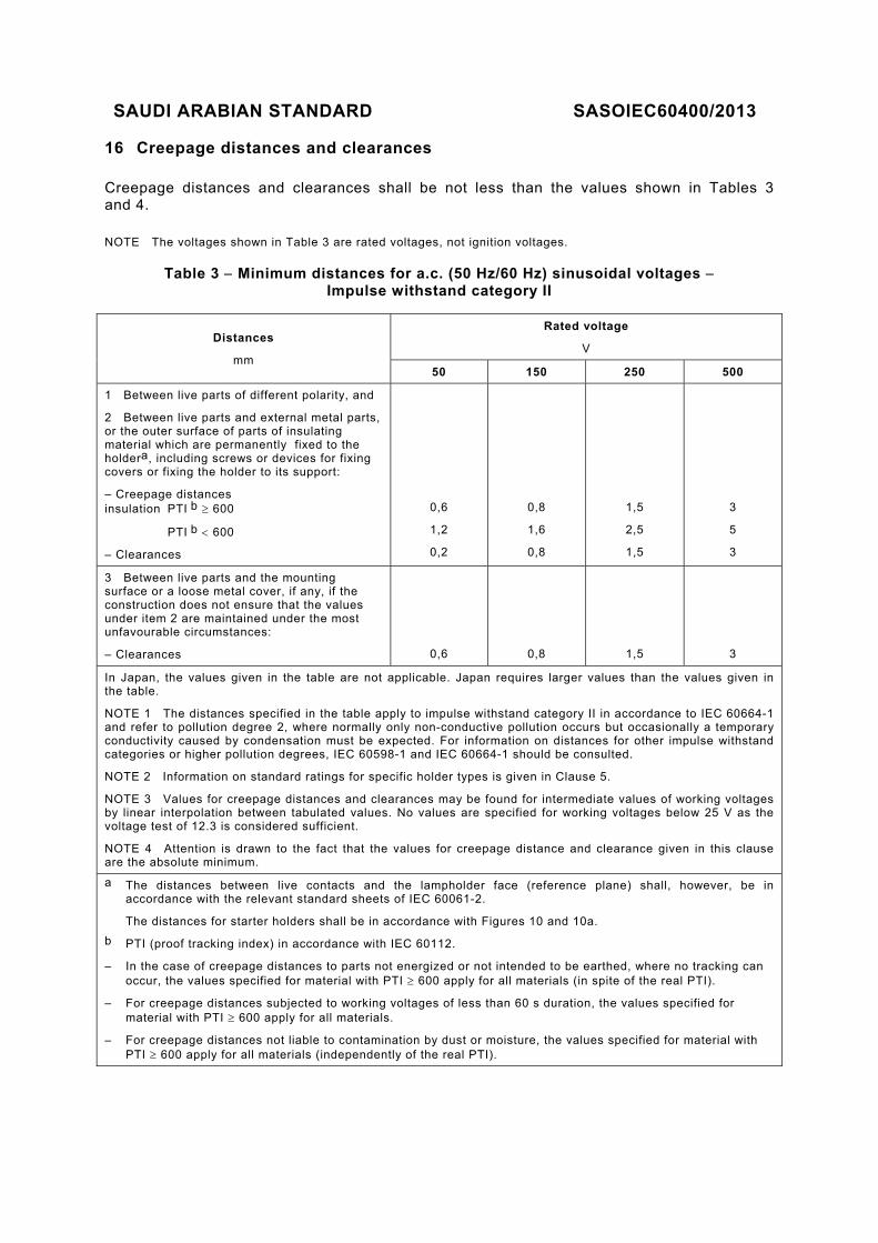
16 Creepage distances and clearances
Creepage distances and clearances shall be not less than the values shown in Tables 3 and 4.
NOTE The voltages shown in Table 3 are rated voltages, not ignition voltages.
Table 3 Minimum distances for a.c. (50 Hz/60 Hz) sinusoidal voltages Impulse withstand category II
Distances
mm
Rated voltage
V
50 150 250 500
1 Between live parts of different polarity, and
2 Between live parts and external metal parts, or the outer surface of parts of insulating material which are permanently fixed to the holdera, including screws or devices for fixing covers or fixing the holder to its support:
– Creepage distances insulation PTI b 600
PTI b 600
– Clearances
0,6
1,2
0,2
0,8
1,6
0,8
1,5
2,5
1,5
3
5
3
3 Between live parts and the mounting surface or a loose metal cover, if any, if the construction does not ensure that the values under item 2 are maintained under the most unfavourable circumstances:
– Clearances
0,6
0,8
1,5
3
In Japan, the values given in the table are not applicable. Japan requires larger values than the values given in the table.
NOTE 1 The distances specified in the table apply to impulse withstand category II in accordance to IEC 60664-1 and refer to pollution degree 2, where normally only non-conductive pollution occurs but occasionally a temporary conductivity caused by condensation must be expected. For information on distances for other impulse withstand categories or higher pollution degrees, IEC 60598-1 and IEC 60664-1 should be consulted.
NOTE 2 Information on standard ratings for specific holder types is given in Clause 5.
NOTE 3 Values for creepage distances and clearances may be found for intermediate values of working voltages by linear interpolation between tabulated values. No values are specified for working voltages below 25 V as the voltage test of 12.3 is considered sufficient.
NOTE 4 Attention is drawn to the fact that the values for creepage distance and clearance given in this clause are the absolute minimum.
a The distances between live contacts and the lampholder face (reference plane) shall, however, be in accordance with the relevant standard sheets of IEC 60061-2.
The distances for starter holders shall be in accordance with Figures 10 and 10a.
b PTI (proof tracking index) in accordance with IEC 60112.
– In the case of creepage distances to parts not energized or not intended to be earthed, where no tracking can occur, the values specified for material with PTI 600 apply for all materials (in spite of the real PTI).
– For creepage distances subjected to working voltages of less than 60 s duration, the values specified for material with PTI 600 apply for all materials.
– For creepage distances not liable to contamination by dust or moisture, the values specified for material with PTI 600 apply for all materials (independently of the real PTI).

SAUDI ARABIAN STANDARD SASOIEC 60400/2013
33
Table 4 – Minimum distances for non-sinusoidal pulse voltages
Rated pulse peak voltage kV 2 2,5 3 4 5 6 8
Minimum clearance mm 1 1,5 2 3 4 5,5 8
For distances subjected to both sinusoidal voltages and non-sinusoidal pulse voltages, the minimum required distance shall not be less than the highest value indicated in either table.
Creepage distances shall not be less than the required minimum clearance.
For holders designed for use in class II luminaires, compliance with this requirement is checked in accordance with the conditions of Section 11 of IEC 60598-1 when the luminaire is complete with the lamp(s) and starter(s) inserted.
Between the lamp contacts of lampholders, the creepage distance or clearance shall be not less than:
– for lampholder G10q: 1,5 mm;
– for other lampholders: 2 mm.
Compliance is checked by measurement, made on the holder with and without external conductors of the largest cross-sectional area required in 9.3 connected to its terminals.
Completely sealed-off or compound-filled distances are exempted from these requirements.
The contribution to the creepage distance of any groove less than 1 mm wide is limited to its width.
NOTE Creepage distances are measured in air, along the surface of the insulating material.
17 Resistance to heat, fire and tracking
17.1 Holders shall be sufficiently resistant to heat.
For lampholders for double-capped fluorescent lamps, for 2G13 and G10q lampholders, and for starterholders, compliance is checked by one of the following tests a) or b) at the discretion of the manufacturer.
Unless otherwise specified, the test of item a) shall be carried out.
For lampholders for single-capped fluorescent lamps (with the exception of 2G13 and G10q lampholders), compliance is checked by the test of item c).
a) The specimen is tested in a heating cabinet at a temperature of 100 °C 5 °C or (T + 20) 5 °C for T-marked holders; the duration of the test shall be 168 h (seven days).
In the case of holders intended to provide an IP classification greater than IP20 where the maximum operating temperature of the gaskets is different from the above temperatures, the separate set of gaskets (see 4.4) shall be tested at the same time in a heating cabinet set at the temperature given in the manufacturer's mounting instructions.
After the test, the gaskets of the holders shall be replaced by those tested separately.
b) G13 lampholders are placed either on a steel test cap A (for lampholders intended for lamps with a nominal tube diameter of 25 mm – see IEC 60081), or on a test cap B (for
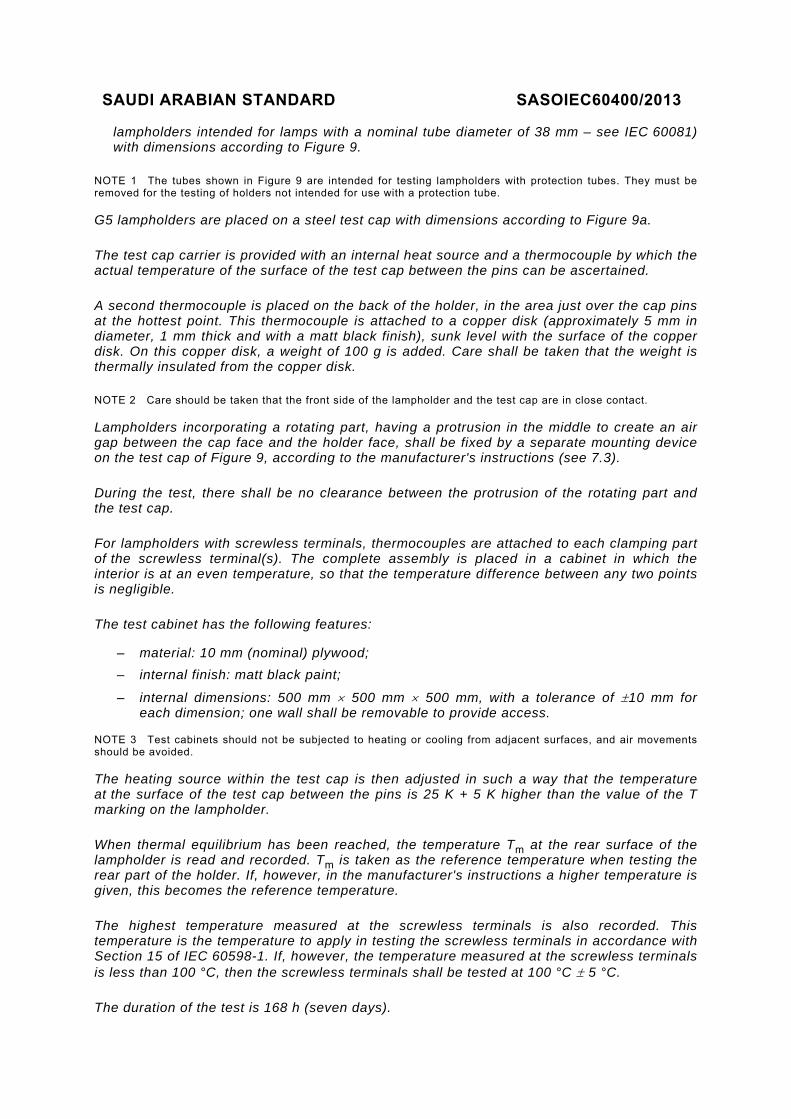
SAUDI ARABIAN STANDARD SASOIEC60400/2013
lampholders intended for lamps with a nominal tube diameter of 38 mm – see IEC 60081) with dimensions according to Figure 9.
NOTE 1 The tubes shown in Figure 9 are intended for testing lampholders with protection tubes. They must be removed for the testing of holders not intended for use with a protection tube.
G5 lampholders are placed on a steel test cap with dimensions according to Figure 9a.
The test cap carrier is provided with an internal heat source and a thermocouple by which the actual temperature of the surface of the test cap between the pins can be ascertained.
A second thermocouple is placed on the back of the holder, in the area just over the cap pins at the hottest point. This thermocouple is attached to a copper disk (approximately 5 mm in diameter, 1 mm thick and with a matt black finish), sunk level with the surface of the copper disk. On this copper disk, a weight of 100 g is added. Care shall be taken that the weight is thermally insulated from the copper disk.
NOTE 2 Care should be taken that the front side of the lampholder and the test cap are in close contact.
Lampholders incorporating a rotating part, having a protrusion in the middle to create an air gap between the cap face and the holder face, shall be fixed by a separate mounting device on the test cap of Figure 9, according to the manufacturer's instructions (see 7.3).
During the test, there shall be no clearance between the protrusion of the rotating part and the test cap.
For lampholders with screwless terminals, thermocouples are attached to each clamping part of the screwless terminal(s). The complete assembly is placed in a cabinet in which the interior is at an even temperature, so that the temperature difference between any two points is negligible.
The test cabinet has the following features:
– material: 10 mm (nominal) plywood;
– internal finish: matt black paint;
– internal dimensions: 500 mm 500 mm 500 mm, with a tolerance of 10 mm for each dimension; one wall shall be removable to provide access.
NOTE 3 Test cabinets should not be subjected to heating or cooling from adjacent surfaces, and air movements should be avoided.
The heating source within the test cap is then adjusted in such a way that the temperature at the surface of the test cap between the pins is 25 K + 5 K higher than the value of the T marking on the lampholder.
When thermal equilibrium has been reached, the temperature Tm at the rear surface of the lampholder is read and recorded. Tm is taken as the reference temperature when testing the rear part of the holder. If, however, in the manufacturer's instructions a higher temperature is given, this becomes the reference temperature.
The highest temperature measured at the screwless terminals is also recorded. This temperature is the temperature to apply in testing the screwless terminals in accordance with Section 15 of IEC 60598-1. If, however, the temperature measured at the screwless terminals is less than 100 °C, then the screwless terminals shall be tested at 100 °C 5 °C.
The duration of the test is 168 h (seven days).
SAUDI ARABIAN STANDARD SASOIEC 60400/2013
35
During test a) or b), the specimen shall not undergo any change impairing its further use, in particular there shall be:
– no reduction of the protection against electric shock;
– no reduction of the protection against ingress of dust or moisture;
– no loosening of electrical contacts.
Detachable gaskets at the mounting surface of the holder are not included in this test, and are tested in the luminaire.
c) For lampholders for single-capped fluorescent lamps (with the exception of 2G13 and G10q lampholders), compliance is checked by the following tests, which are each time carried out on one of the three holders to be submitted to the test.
A test cap complying with the relevant Figures 30, 31, 32, 33, 34, 35, 36, 37 or 38 or, if not available, a test cap with nominal dimensions corresponding to the relevant cap sheets of IEC 60061-1 shall be inserted in two of the holders, the third holder being left empty.
NOTE 4 The test cap does not need to have keys if these keys have only a keying function.
The three holders are then placed for 168 h in a heating cabinet at a temperature of:
(maximum cap temperature + 20) °C 5 °C.
For lampholders which form an integral part of the luminaire, this temperature is replaced by that measured according to the operating conditions given in 12.4.2 of IEC 60598-1, plus 20 K, with a tolerance of 5 °C.
NOTE 5 For information on the maximum cap temperatures, see Annex C of IEC 61199.
The test cap shall be mounted in the cabinet in the vertical holder-up position because the weight of the test cap shall not bear on the holder. A bending moment of 0,3 Nm in relation to the reference plane shall be exerted on one of these holders during the whole test.
This requirement does not apply to lampholders 2G11, 2GX13, GU10q and GZ10q.
NOTE 6 The test with a bending moment is not applicable where additional means of fixing independent from the lampholder are compulsory for the lamp.
The point of application of the bending moment is the test cap axis.
The bending moment shall act in the direction of the plane through the means of retention (retaining springs or catches).
During the test, the holders shall not undergo any change impairing their further use.
After the test, the lampholders shall be removed from the heating cabinet and allowed to cool down without the test caps.
The holders shall comply with the following requirements:
– the lampholders which were left empty during the heating period shall comply with all the relevant lampholder gauges of IEC 60061-3;
– the lampholders which were provided with the test caps during the heating period shall comply with the corresponding minimum retention force.

SAUDI ARABIAN STANDARD SASOIEC60400/2013
17.2 Enclosures and other external parts of insulating material providing protection against electric shock, and parts of insulating material retaining live parts in position, shall be subjected to a ball-pressure test by means of the apparatus shown in Figure 7.
None of the tests required by Clause 17 (except 17.1) are performed on lampholders which are integral with a luminaire, as similar tests are required in Section 13 of IEC 60598-1. However, the operating conditions of these tests will take into account the conditions specific to lampholders and defined in this Clause 17.
The surface of the part under test is placed in the horizontal position and a steel ball of 5 mm diameter is pressed against this surface with a force of 20 N. The test is made in a heating cabinet having a temperature of 25 °C 5 K in excess of the operating temperature (see 6.3), with a minimum temperature of 125 °C when parts retaining live parts in position are tested.
The test load and the supporting means are placed in the heating cabinet for a sufficient time to ensure that they have attained the stabilized testing temperature before the test commences.
The part to be tested is placed in the heating cabinet for a period of 1 h before the test load is applied.
If the surface under test bends, the part where the ball presses is supported. For this purpose, if the test cannot be made on the complete specimen, a suitable part may be cut from it.
The specimen shall be at least 2,5 mm thick, but if such a thickness is not available on the specimen, then two or more pieces are placed together.
For lampholders with T marking tested according to item b) in 17.1, the temperature in the heating cabinet is (T + 25) 5 °C when testing the front of the holder and Tm 5 °C when testing the rear of the holder, but with a minimum temperature of 125 °C when parts retaining live parts in position are tested.
After 1 h, the ball is removed from the specimen, which is then immersed within 10 s in cold water for cooling down to approximately room temperature. The diameter of the impression caused by the ball is measured and shall not exceed 2 mm.
The test is not made on parts of ceramic material.
NOTE In the event of curved surfaces, the shorter axis is measured if the indent is elliptical. In case of doubt, the depth of the impression p is measured and the diameter calculated using the formula:
Ø = 2 )(5 pp
17.3 External parts of insulating material providing protection against electric shock and parts of insulating material retaining live parts in position shall be resistant to flame and ignition.
For materials other than ceramic, compliance is checked by the tests in 17.4 or 17.5.
17.4 External parts of insulating material providing protection against electric shock are subjected to the glow-wire test in accordance with IEC 60695-2-11, subject to the following details.
– The specimen is a complete holder. It may be necessary to take away parts of the holder to perform the test, but care should be taken to ensure that the test conditions are not significantly different from those occurring in normal use.

SAUDI ARABIAN STANDARD SASOIEC 60400/2013
37
– The specimen is mounted on the carriage and pressed against the glow-wire tip with a force of 1 N, preferably 15 mm or more from the upper edge, into the centre of the surface to be tested. The penetration of the glow-wire into the specimen is mechanically limited to 7 mm.
If it is not possible to perform the test described above because the specimen is too small, the test is performed on a separate specimen of the same material, 30 mm 30 mm, and with a thickness equal to the smallest thickness of the specimen.
– The temperature of the tip of the glow-wire shall be 650 °C.
After 30 s, the specimen is withdrawn from contact with the glow-wire tip.
The glow-wire temperature and the heating current are constant for 1 min prior to commencing the test.
Care should be taken to ensure that heat radiation does not influence the specimen during this period.
The glow-wire tip temperature is measured by means of a sheathed fine-wire thermocouple, constructed and calibrated as described in IEC 60695-2-11.
– Any flame or glowing of the specimen shall extinguish within 30 s of withdrawing the glow-wire, and any flaming drops shall not ignite a piece of tissue paper, as specified in definition 4.187 of ISO 4046-4, spread out horizontally 200 mm 5 mm below the specimen.
17.5 Parts of insulating material retaining live parts in position shall be subjected to the needle-flame test in accordance with IEC 60695-11-5, subject to the following details.
– The test specimen is a complete holder. It may be necessary to take away parts of the holder to perform the test, but care should be taken to ensure that the test conditions are not significantly different from those occurring in normal use.
– The test flame is applied to the centre of the surface to be tested.
– The duration of application is 10 s.
– Any self-sustaining flame shall extinguish within 30 s of removal of the test flame, and any flaming drops shall not ignite a piece of tissue paper spread out horizontally 200 mm 5 mm below the test specimen.
17.6 For holders other than ordinary holders, insulating parts retaining live parts in position shall have adequate resistance to tracking.
For materials other than ceramic, compliance is checked by the proof-tracking test in accordance with IEC 60112, subject to the following details.
– If the specimen has no flat surface of at least 15 mm 15 mm, the test may be carried out on a flat surface with reduced dimensions provided drops of liquid do not flow off the specimen during the test. No artificial means should, however, be used to retain the liquid on the surface. In case of doubt, the test may be made on a separate strip of the same material having the required dimensions and manufactured by the same process.
– If the thickness of the specimen is less than 3 mm, two, or if necessary more, specimens should be stacked to obtain a thickness of at least 3 mm.
– The test shall be made at three places of the specimen or on three specimens.
– The electrodes shall be of platinum and the test solution A described in 7.3 of IEC 60112 shall be used.
– The specimen shall withstand 50 drops without failure at a test voltage of PTI 175.
SAUDI ARABIAN STANDARD SASOIEC60400/2013
– A failure has occurred if a current of 0,5 A or more flows for at least 2 s in a conducting
path between the electrodes on the surface of the specimen, thus operating the overcurrent relay, or if the specimen burns without releasing the overcurrent relay.
– Clause 9 of IEC 60112 regarding determination of erosion does not apply.
18 Resistance to excessive residual stresses (season cracking) and to rusting
18.1 Contacts and other parts of rolled sheets of copper or copper alloy, the failure of which might cause the holder to become unsafe, shall not be damaged due to excessive residual stresses.
Compliance is checked by the following test.
The surface of the specimens is carefully cleaned, varnish being removed by acetone, grease and fingerprints by petroleum spirit or the like.
The specimens are placed for 24 h in a test cabinet, the bottom of which is covered by an ammonium chloride solution having a pH value of 10 (for details of the test cabinet, the test solution and the test procedure, see Annex B).
After this treatment, the specimens are washed in running water; 24 h later they shall show no cracks when inspected at an optical magnification of 8.
Cracks which may occur in very restricted areas of the outer shell of metal lampholders near the fixing areas of the insulating ring shall not be considered.
NOTE In order not to influence the results of the test, the specimens should be handled with care.
18.2 Ferrous parts, the rusting of which may endanger the safety of the holder, shall be adequately rust-protected.
Compliance is checked by the following test.
All grease is removed from the parts to be tested by immersion in a suitable degreasing agent for 10 min. The parts are then immersed for 10 min in a water solution of 10 % ammonium chloride at a temperature of 20 °C 5 °C. Without drying, but after shaking off drops of water, the parts are placed for 10 min in a box containing air saturated with moisture at a temperature of 20 °C 5 °C.
After the specimens have been dried for 10 min in a heating cabinet at a temperature of 100 °C 5 °C, their surfaces shall show no signs of rust.
For small helical springs and the like, and for ferrous parts exposed to abrasion, a layer of grease is deemed to provide sufficient rust protection.
Such parts are not subjected to the test.

SAUDI ARABIAN STANDARD SASOIEC 60400/2013
39
ZStop
Base plate
Bar, pressing the mountingsheet against the stop
tq
r
Clamping jaws*; overlapping on mounting sheet: 10 mm
Mounting sheet (see figure 2)Fixing screws
p
The drawing is intended only to illustrate the essential dimensions of the jig.
* For certain lampholders, e.g. twin-lampholders, it may be necessary to use two-piece clamping jaws.
Reference Dimension
mm Tolerance
mm
Z 1) 0,05
p 65 0,1
q 60,2 + 0,1 – 0,0
r 5 0,1
t 40 0,1
1) Z = 69,5 mm for testing lampholders G5 (derived from dimension Amax of a 4 W lamp, see IEC 60081).
Z = 367,4 mm for testing lampholders G13 (derived from dimension Amax of a 15 W lamp, see IEC 60081).
PURPOSE: Testing of a combined pair of holders regarding compliance with the specified "Go" gauges and those for testing contact-making.
TESTING: The mounting sheets with a matching pair of holders are inserted into the mounting jig, pressed against the stop and fixed by use of the clamping jaws. In this position the gauges are applied.
Figure 1 – Mounting jig for the testing of lampholders
SAUDI ARABIAN STANDARD SASOIEC60400/2013
S
P R
Q
Holder cut-out centred to this line
Material: steel
Stop side*
* This side shall be marked.
For holders requiring a vertical mounting surface, a steel angle shall be added to the mounting sheet.
When applying a force of 50 N to this angle in the height and in the direction of the lampholder axis, the lampholder shall not deviate by more than 0,2 mm from its original position.
The drawing is intended only to illustrate the essential dimensions of the mounting sheet.
Reference Dimension
mm Tolerance
mm
P 70 0,1
Q 60 0,1
R 2 0,5
S 1) 1,0 0,05
1) If the holder is designed for a lower material thickness, only the area required for the mounting of the holder is reduced to this specific value.
Figure 2 – Mounting sheet
IEC 1027/08

SAUDI ARABIAN STANDARD SASOIEC 60400/2013
41
Support
Holder
Test cap (see figure 4)Specified plunger travel*
Direction of test force
Fixture frame
Mounting sheet (see figure 2) Clamping jaws; overlapping onmounting sheet: 10 mm
The fixture shown is intended for testing single lampholders. For testing twin-lampholders, modifications will be necessary.
PURPOSE: To check, in case of doubt, whether the lampholder shall be considered as a flexible or an inflexible one.
TESTING: The holder, mounted on the mounting sheet, is placed on the support and the test cap is inserted into the holder. The mounting sheet is then moved in such a way that the test cap (***) is fixed between holder and fixture frame without clearance. In this position the mounting sheet is fixed by the use of the clamping jaws. A force is applied via the plunger to the test cap until the specified plunger travel* is achieved. The force required shall not exceed 15 N for lampholders G5 and 30 N for lampholders G13. This procedure is repeated 10 times.
After this test, no clearance shall exist between test cap and fixture frame, nor between test cap and holder. If the holder complies, it is deemed to be a flexible lampholder; if not it is an inflexible one.
* The plunger travel is equal to the required minimum axial contact movement, which is:
– for a pair of holders for side entry: 3 mm + mounting tolerance**;
– for a pair of holders for axial insertion: 3 mm + maximum cap pin length (= 7,62 mm; under consideration) + mounting tolerance**.
If the combined pair of holders consists of two flexible holders, each holder has to provide half of the required contact movement.
** According to the manufacturer's instructions (see 7.3).
*** The relevant test caps are described in Figure 4.

SAUDI ARABIAN STANDARD SASOIEC60400/2013
Figure 3 – Fixture for the testing of lampholder flexibility
D
E
A
r
E/2
See note 1)
F
H
* This part of the gauge and the cap pins shall be of hardened steel.
Reference
Dimension mm
Tolerance
G5 G13 mm
A 1) 15,5 25,6 0,1
D 4,75 12,7 0,05
E 2,37 0,02
F 7,1 0,05
H 1) 35,0 0,1
r 1) 0,5 + 0,3 – 0,0
1) These test caps differ from the test caps used in Clause 14 by the material and the additional dimensions A, H and r.
Figure 4 – Test caps G5 and G13
IEC 1029/08

SAUDI ARABIAN STANDARD SASOIEC 60400/2013
43
Dimensions in millimetres
Specimen
Mounting fixture
Frame
1000 ±1 mm
Height of fall
NOTE This drawing has been retained in this standard for information, although there is a basic standard. In case of doubt regarding the drawing, refer to IEC 60068-2-75.
Figure 5 – Impact test apparatus
IEC 1030/08
SAUDI ARABIAN STANDARD SASOIEC60400/2013
Dimensions in millimetres
y
175 ±1
y
200 min.
A
ASheet of plywood
Pivot
A-A
35 ±2
2
8
45°
7
45°
7
155±1175+10-0 175
+10-0
Figure 5a – Mounting support
IEC 1031/08

SAUDI ARABIAN STANDARD SASOIEC 60400/2013
45
D
c
ES
Q
B
F
J
ØA
Reference Dimension
mm Tolerance
mm
A 18,5 0,01
B 12,8 0,05
D 13,0 0,05
E 2,37 0,02
F 6,4 0,05
J 0,5 0,1
Q 1,7 0,05
S 7,2 0,05
c 25,0 0,2
Figure 6 – Test cap for the test of Clause 13 for lampholders 2GX13
IEC 1032/08

SAUDI ARABIAN STANDARD SASOIEC60400/2013
R=2,5mm
Spherical
Specimen
NOTE For information this drawing has been retained in this standard, although there is a basic standard. In case of doubt regarding the drawing, refer to IEC 60068-2-75.
Figure 7 – Ball-pressure apparatus
Dimensions in millimetres
30
4060
30
70
35
Support
Specimen for flush mounting
Specimen for surface or semi-flush mounting
50 50
70
Figure 8 – Bracket for fixing lampholders for the impact test
IEC 1033/08
IEC 1034/08

SAUDI ARABIAN STANDARD SASOIEC 60400/2013
47
Dimensions in millimetres
Thickness not less than 2 mm
Height accordingto manufacturer'sinstructions
Lampholder
Step for protection tube
e (2x)
100 g
Mass
d
n
f
Test capMaterial: steel
Heat source - available space
Protection tube (if applicable)
Thermocouples
b
a
c
70 ± 0,2*
20 ± 0,2*
20 ± 0,2*
Test cap carrier 1)
175 + 1*
c - 6*
Figure 9 – Test caps and test assembly for testing of resistance to heat of lampholders G13 with T marking (see 17.1)
Reference
Test cap mm
Tolerance
A B mm
a 25,8 36,5 + 0,0 – 0,1
b 2) 26 38 + 0,0 – 0,1
c 38 3) 50 0,1
d 12,7 0,05
e 2,5 0,05
f 7,1 + 0,0 – 0,1
n 8,71 + 0,1 – 0,0
The test cap shall be provided with an internal heat source, e.g. a cartridge heater which provides equal heat distribution over the front side of the test cap. 1) Test cap and test cap carrier need not be separated
parts. 2) Dimensions b refer to the nominal lamp diameters.
They do not take into account the possible eccentricity of the caps referred to the lamp tube.
3) Other diameters can also be used (e.g. diameters of 40 mm and 50 mm) by means of interchangeable rings.
* Recommended design values for the test cap carrier. Adoption of these values will serve the unification of test devices.
IEC 1035/08

SAUDI ARABIAN STANDARD SASOIEC60400/2013
Dimensions in millimetres
100 g
Mass
d
n
f
Test capMaterial: steel
Heat source - available space
Thermocouples
b
a
45 ± 0,2*
20 ± 0,2*
20 ± 0,2*
Test cap carrier 1)
175 + 1*
25 ± 0,2*
Thickness not less than 2 mm
Lampholder
e (2x)
Reference Test cap
mm Tolerance
mm
a 15,75 + 0,0 – 0,1
b 2) 16,0 + 0,0 – 0,1
d 4,75 + 0,05 – 0,05
e 2,5 + 0,05 – 0,05
f 7,1 + 0,0 – 0,1
n 8,71 + 0,1 – 0,0
Figure 9a – Test cap and test assembly for testing of resistance to heat of lampholders G5 with T marking (see 17.1)
The test cap shall be provided with an internal heat source, for example a cartridge heater which provides equal heat distribution over the front side of the test cap. 1) Test cap and test cap carrier need not be separated parts. 2) Dimension b refers to the nominal lamp diameters. It does not take
into account the possible eccentricity of the caps referred to the lamp tube.
* Recommended design values for the test cap carrier. Adoption of these values will serve the unification of test devices.
IEC 1036/08

SAUDI ARABIAN STANDARD SASOIEC 60400/2013
49
E1
A
E2
B
D
U1
U2
T3
H
S
Contacts
Insulator
T1
Contacts
Alternative contact position
T2
1) Rest position of contacts.
2) Contacts fully depressed.
The drawing is intended only to indicate the dimensions to be checked.
Dimensions in millimetres
Figure 10 – Dimensions of starterholder
Reference Min. mm
Max. mm
A 12,5 12,9
B 21,7 –
D 5,4 –
E1 8,7 9,2
E2 16,2 16,7
H – 28,0
S – 1,5
T1 1) – 1,5
T2 2) 2,5 –
T3 2,3 –
U1 1) – 17,0
U2 2) 18,0 –
45° –
IEC 1037/08

SAUDI ARABIAN STANDARD SASOIEC60400/2013
E1
A
E2
B
D
U1
U2
T3
H
S
Contacts
Insulator
T1
Contacts
Alternative contact position
T2
V
W
1) Rest position of contacts.
2) Contacts fully depressed.
Figure 10a – Dimensions of holder intended for accepting only starters according to Annex B of IEC 60155
The drawing is intended only to indicate the dimensions to be checked.
Reference Min. mm
Max. mm
A 12,5 12,9
B 21,7 –
D 5,4 –
E1 8,7 9,2
E2 16,2 16,7
H – 28,0
S – 1,5
T1 1) – 1,5
T2 2) 2,5 –
T3 2,3 –
U1 1) – 17,0
U2 2) 18,0 –
V 2,2 2,5
W 3,6 4,1
45° – IEC 1038/08

SAUDI ARABIAN STANDARD SASOIEC 60400/2013
51
HS
D E
W
T
V A
B
Edges slightly chamfered
The drawing is intended only to illustrate the essential dimensions of the gauges.
Reference Dimension
mm
Tolerance
Gauge A Gauge B mm
A 12,90 12,50 0,005
B 21,5 21,5 + 0,01
– 0,0
D 5,0 5,0 + 0,01 – 0,0
E 3,2 3,2 + 0,01 – 0,0
H 38 38 0,2
S 1,7 1,7 + 0,0 – 0,01
T 2,2 2,2 + 0,01 – 0,0
V 2,7 2,7 + 0,0 – 0,01
W 2,5 2,5 + 0,0
– 0,01
Figure 11 – "Go" plug gauges for starterholders
PURPOSE: To check starterholders with regard to the fit of a "maximum" starter. Gauge A is also used for the torsion test. TESTING: Each of the gauges A and B shall in turn enter the starterholder smoothly until it reaches the normal operating position of the starter.
IEC 1039/08

SAUDI ARABIAN STANDARD SASOIEC60400/2013
Edges slightly chamfered
L
Test circuit
H
D E
W
T
V A
B
The drawing is intended only to illustrate the essential dimensions of the gauge.
Reference Dimension mm
Tolerance mm
A 12,70 0,005
B 20,0 0,1
D 4,5 + 0,0
– 0,01
E 2,6 + 0,0
– 0,01
H 38,0 0,2
L 4,3 + 0,01
– 0,0
T 1,9 + 0,0
– 0,01
V 3,0 0,01
W 4,0 + 0,1
– 0,0
Figure 12 – Plug gauge for starterholders for testing contact making and retention
NOTE Mass of the gauge: approximately 75 g. PURPOSE: To check the retention and contact-making of a "minimum" starter in a starterholder, the contact force being determined inter alia by the starter-pin spacing. For starterholders in which the contact force is practically independent from the starter-pin spacing, the special plug gauge shown in Figure 13 should be used. TESTING: The starterholder shall be assumed to be correct if the indicator lamp lights up when the gauge is inserted in the normal operating position of the starter. In this position, the gauge shall be retained by the starterholder. This test shall be made after checking with the gauges shown in Figure 11.
IEC 1040/08

SAUDI ARABIAN STANDARD SASOIEC 60400/2013
53
ØD ØE
T
Edges slightly chamferedTest circuit
L
The drawing is intended only to illustrate the essential dimensions of the gauge.
Reference Dimension mm
Tolerance mm
D 4,7 + 0,0 – 0,01
E 2,8 + 0,0 – 0,01
L 4,3 + 0,01 – 0,0
T 1,9 + 0,0 – 0,01
PURPOSE: To check contact-making in starterholders in which the contact force is practically independent from the starter-pin spacing.
TESTING: When the gauge is inserted in both contacts in turn, the indicator lamp shall light without flickering in all possible positions of the gauge.
The test shall be made after checking with the gauges shown in Figure 11.
Figure 13 – Special plug gauge for starterholders for testing contact making
E E/2
F
D
E
D
E/2
F
Reference Dimension
mm Tolerance
mm
Reference Dimension
mm Tolerance
mm
D 4,75 0,05 D 12,7 0,05
E 2,37 0,02 E 2,37 0,02
F 7,1 0,05 F 7,1 0,05
Figure 14 – Test cap for the test of Figure 15 – Test cap for the test of
IEC 1041/08
IEC 1042/08 IEC 1043/08
SAUDI ARABIAN STANDARD SASOIEC60400/2013
Clause 13 for lampholders G5 Clause 13 for lampholders G13

SAUDI ARABIAN STANDARD SASOIEC 60400/2013
55
D
EE/2
F
A
Reference Dimension
mm
Tolerance
2G13-41 2G13-56 2G13-92 2G13-152 mm
A 41 56 92 152 0,1
D 12,7 0,05
E 2,37 0,02
F 7,1 0,05
Figure 16 – Test cap for the test of Clause 13 for lampholders 2G13
F
EE/2E
D
E/2
F
Reference Dimension
mm Tolerance
mm
Reference Dimension
mm Tolerance
mm
D 19,84 0,05 E 5,96 0,02
E 3,32 0,02 F 18,0 0,05
F 15,88 0,05
Figure 17 – Test cap for the test of Clause 13 for lampholders G20
Figure 18 – Test cap for the test of Clause 13 for lampholders Fa6
IEC 1044/08
IEC 1046/08 IEC 1045/08

SAUDI ARABIAN STANDARD SASOIEC60400/2013
D
C
E
F
E/2
Reference Dimension
mm Tolerance
mm
C 6,35 0,05
D 7,92 0,05
E 2,37 0,02
F 7,1 0,05
Figure 19 – Test cap for the test of Clause 13 for lampholders G10q, GU10q and GZ10q
E
F
E/2
Reference Dimension
mm Tolerance
mm
E 7,94 0,02
F 8,25 0,05
Figure 20 – Test cap for the test of Clause 13 for lampholders Fa8
IEC 1047/08
IEC 1048/08
SAUDI ARABIAN STANDARD SASOIEC 60400/2013
57
D
E
TL
A
Reference Dimension
mm Tolerance
mm
A 12,7 0,05
D 4,85 0,02
E 2,9 0,02
L 4,1 0,05
T 2,05 0,05
Figure 21 – Test starter for the test of Clause 13
IEC 1049/08
SAUDI ARABIAN STANDARD SASOIEC60400/2013
K G
N
D
r1
r2
J
H
E
r3
Reference Dimension
mm Tolerance
mm
D 1,41 0,05
E 8,7 0,05
G 16,49 0,05
H 2,6 0,05
J 5,3 0,05
K 7,08 0,05
N 8,0 0,1
r1 0,85 0,05
r2 0,89 0,05
r3 Max. 0,9
Figure 22 – Test cap for the test of Clause 13 for lampholders R17d
IEC 1050/08

SAUDI ARABIAN STANDARD SASOIEC 60400/2013
59
D D
A
F
J
E
Reference Dimension
mm Tolerance
mm
A 22,0 0,05
D 11,0 0,05
E 2,37 0,02
F 6,4 0,05
J 0,5 0,1
Figure 23 – Test cap for the test of Clause 13 for lampholders 2G11
IEC 1051/08

SAUDI ARABIAN STANDARD SASOIEC60400/2013
F
D
J
E
Reference Dimension
mm Tolerance
mm
D 23,0 0,05
E 2,37 0,02
F 6,4 0,05
J 0,5 0,1
Figure 24 – Test cap for the test of Clause 13 for lampholders G23 and GX23
IEC 1052/08

SAUDI ARABIAN STANDARD SASOIEC 60400/2013
61
E
F
E/2
D
Reference Dimension
mm Tolerance
mm
D 8,0 0,05
E 2,37 0,02
F 7,1 0,05
Figure 25 – Test cap for the test of Clause 13 for lampholders GR8
D
D1
E
F
E/2
Reference Dimension
mm Tolerance
mm
D 8,0 0,05
D1 6,35 0,05
E 2,37 0,02
F 7,1 0,05
Figure 26 – Test cap for the test of Clause 13 for lampholders GR10q
IEC 1053/08
IEC 1054/08

SAUDI ARABIAN STANDARD SASOIEC60400/2013
V
U
F
EE/2
Reference Dimension
mm Tolerance
mm
E 2,37 0,02
F 7,10 0,05
U 6,35 0,05
V 7,92 0,05
Figure 27 – Test cap for the test of Clause 13 for lampholders GX10q and GY10q
IEC 1055/08

SAUDI ARABIAN STANDARD SASOIEC 60400/2013
63
F
D1
D2
See note 1)
See note 2)
J
E
Reference Dimension
mm Tolerance
mm
D1 23,0 0,05
D2 8,0 0,05
E 2,37 0,02
F 6,4 0,05
J 0,5 0,1
1) These pins shall be removed for testing lampholders G24d-1, G24d-2 and G24d-3.
2) These pins shall be removed for testing lampholders GY24d-1, GY24d-2 and GY24d-3.
IEC 1056/08

SAUDI ARABIAN STANDARD SASOIEC60400/2013
Figure 28 – Test cap for the test of Clause 13 for lampholders G24, GX24 and GY24
See note 1)See note 2)
F
D1
J
E
D2
Reference Dimension
mm Tolerance
mm
D1 31,0 0,05
D2 8,0 0,05
E 2,37 0,02
F 6,4 0,05
J 0,5 0,1
1) These pins shall be removed for testing lampholders G32d-1, G32d-2, G32d-3, G32d-4 and G32d-5.
2) These pins shall be removed for testing lampholders GY32d-1, GY32d-2, GY32d-3, GY32d-4 and GY32d-5.
Figure 29 – Test cap for the test of Clause 13 for lampholders G32 and GY32
IEC 1057/08

SAUDI ARABIAN STANDARD SASOIEC 60400/2013
65
2
1
B
A
E
R
Tr3
L1
L2
D
r4
F
Y
M
N1
N2
Reference plane
Z
S
K2
P
r2
K1
* Measured at distance N1
** Measured at distance N2.
Figure 30 – Test cap for the test of 17.1 for lampholders G23
Reference Dimension
mm Tolerance
mm
P 21,0 0,02
R B/2 –
S 9,0 0,05
T 4,5 0,02
Y 18 0,2
Z 0,5 0,05
r2 0,8 0,05
r3 0,5 0,05
r4 E/2 –
1 35° 1°
2 30° 1°
Reference Dimension
mm Tolerance
mm
A 32,5 0,02
B 18,1 0,02
D 23,0 0,01
E 2,67 0,02
F 6,8 0,02
K1* 16,3 0,02
K2** 15,75 0,02
L1* 13,9 0,02
L2** 13,35 0,02
M 23,0 + 0,02 – 0,05
N1 0,5 –
N2 21,0 –
.
IEC 1058/08
SAUDI ARABIAN STANDARD SASOIEC60400/2013
E
G
M
T
NP
r2
Section I-I
D
A
R
I I
Br
J
H
r1
L
K
C
F
P1
Reference plane
Figure 31 – Test cap for the test of 17.1 for lampholders GR8
Reference Dimension
mm Tolerance
mm
A 15,5 0,02
B 20,4 0,02
C 31,0 0,2
D 8,0 0,01
E 2,54 0,02
F 7,77 0,01
G 1,27 0,02
H 3,3 0,02
J 19,3 0,02
K 16,2 0,01
Reference Dimension
mm Tolerance
mm
L 22,0 0,02
M 20,3 0,02
N 3,5 0,02
P 9,9 0,02
P1 7,0 0,02
R 9,0 0,02
T 22,0 0,1
r 0,8 0,05
r1 E/2 –
r2 0,3 0,2
IEC 1059/08

SAUDI ARABIAN STANDARD SASOIEC 60400/2013
67
E
G
M
T
NP
r2
Section I-I
D
A
RI I
Br
J
H
r1
L
D1
C
F
P1
K
Reference plane
Reference Dimension
mm Tolerance
mm
L 22,0 0,02
M 20,3 0,02
N 3,5 0,02
P 9,9 0,02
P1 7,0 0,02
R 9,0 0,02
T 22,0 0,1
r 0,8 0,05
r1 E/2 –
r2 0,3 0,2
Figure 32 – Test cap for the test of 17.1 for lampholders GR10q
Reference Dimension
mm Tolerance
mm
A 15,5 0,02
B 20,4 0,02
C 31,0 0,2
D 8,0 0,01
D1 6,35 0,01
E 2,54 0,02
F 7,77 0,01
G 1,27 0,02
H 3,3 0,02
J 19,3 0,02
K 10,0 0,01
IEC 1060/08
SAUDI ARABIAN STANDARD SASOIEC60400/2013
G
r5
K
H
FR2
R3
D
CQ
U
B
I
R4
R2
a
LJ
2
1
3
Reference plane A
N
Detail a
R1V
E
Figure 33 – Test cap for the test of 17.1 for lampholders GX10q
Reference Dimension
mm Tolerance
mm
A 36,2 0,02
B 18,0 0,02
C 6,1 0,02
D 10,2 0,02
E 2,54 0,02
F 7,62 0,02
G 1,27 0,02
H 3,3 0,02
I 15,0 0,2
J 6,4 0,05
K 8,15 0,02
L 0,5 0,05
Reference Dimension
mm Tolerance
mm
N 42,2 0,02
Q 21,2 0,02
R1 B/2 –
R2 1,0 0,05
R3 0,5 0,05
R4 2,0 0,05
U 6,35 0,01
V 7,92 0,01
r5 E/2 –
1 45° 1°
2 15° 1°
3 45° 1°
IEC 1061/08
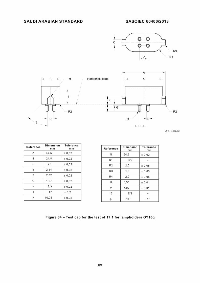
SAUDI ARABIAN STANDARD SASOIEC 60400/2013
69
V
E
G
r5
K
H
FR2
R3
C
U
B
I
R4
R2
Reference plane A
N
R1
Figure 34 – Test cap for the test of 17.1 for lampholders GY10q
Reference Dimension
mm Tolerance
mm
N 54,2 0,02
R1 B/2 –
R2 2,0 0,05
R3 1,0 0,05
R4 2,0 0,05
U 6,55 0,01
V 7,92 0,01
r5 E/2 –
45° 1°
Reference Dimension
mm Tolerance
mm
A 47,5 0,02
B 24,8 0,02
C 7,1 0,02
E 2,54 0,02
F 7,62 0,02
G 1,27 0,02
H 3,3 0,02
I 17 0,2
K 10,05 0,02
IEC 1062/08

SAUDI ARABIAN STANDARD SASOIEC60400/2013
A1
B
D D
A
R
T
r2
Er3
F
Y
Reference plane
r2 Q
S
N
Figure 35 – Test cap for the test of 17.1 for lampholders 2G11
Reference Dimension
mm Tolerance
mm
R B/2 –
S 3,9 0,02
T 7,0 0,02
Y 12,9 0,2
r2 0,2 0,05
r3 E/2 –
45° 1°
Reference Dimension
mm Tolerance
mm
A 22,0 0,01
A1 43,9 0,02
B 23,6 0,02
D 11,0 0,01
E 2,54 0,02
F 6,8 0,02
N 6,5 0,02
Q 1,5 0,02
IEC 1063/08

SAUDI ARABIAN STANDARD SASOIEC 60400/2013
71
L2
D
r4
F
M
N1
Reference plane
2
1
Z
S
K2
P
r2
X
Y
K1
N2
B
A
E
R
r3
L1
* Measured at distance N1
** Measured at distance N2.
Reference Dimension
mm Tolerance
mm
A 32,5 0,02
B 18,1 0,02
D 23,0 0,01
E 2,54 0,02
F 6,8 0,02
K1* 16,3 0,02
K2** 15,75 0,02
L1* 13,9 0,02
L2** 13,35 0,02
M 23,0 + 0,02 – 0,05
N1 0,5 –
N2 21,0 –
Reference Dimension
mm Tolerance
mm
P 21,0 0,02
R B/2 –
S 9,0 0,05
X 3,3 0,02
Y 18 0,2
Z 0,5 0,05
r2 0,8 0,05
r3 0,5 0,05
r4 E/2 –
1 35° 1°
2 30° 1°
. IEC 1064/08

SAUDI ARABIAN STANDARD SASOIEC60400/2013
Figure 36 – Test cap for the test of 17.1 for lampholders GX23
A V B
T
X2
D1
D2
A1
B
R
R1 r3
L1
L2
E
F
Y1
Y
N1
M
r2
K1
K2
S
r2
a
Q
Z
S
P
12
Reference plane
Detail a
See note 1)
See note 2)
X4
X3
X4
X3
X2
Key
P
Specific key configurations
r6N2
G24d-1GX24d-1GY24d-1G24q-1
GX24q-1
G24d-2GX24d-2GY24d-2G24q-2
GX24q-2
G24d-3GX24d-3GY24d-3G24q-3
GX24q-3
Only the test cap for testing lampholders G24q-1 is shown.
Figure 37 – Test cap for the test of 17.1 for lampholders G24, GX24 and GY24
IEC 1065/08

SAUDI ARABIAN STANDARD SASOIEC 60400/2013
73
* Measured at distance N1
** Measured at distance N2.
Figure 37(continued)
Reference Dimension
mm Tolerance
mm
A 28,5 0,02
A1 31,0 0,02
B 35,0 3) 0,02
D1 23,0 0,01
D2 8,0 0,01
E 2,54 0,02
F 6,8 0,02
K1* 16,3 0,02
K2** 15,75 6) 0,02
L1* 13,9 0,02
L2** 13,35 7) 0,02
M 23,0 4) + 0,02 – 0,05
N1 0,5 –
N2 21,0 5) –
P 21,0 0,02
Q 1,2 0,02
R 8,4 0,05
R1 9,0 0,05
S 9,0 0,05
T 4,5 0,02
V 33,0 0,02
X2 6,6 0,01
X3 12,4 0,01
X4 6,2 0,01
Y 5,7 0,2
Y1 18 0,2
Z 0,5 0,05
r2 0,8 0,05
r3 0,5 0,05
r6 E/2 –
1 35° 1°
2 30° 1°
1) These pins shall be removed for testing lampholders GY24d-1, GY24d-2 and GY24d-3.
2) These pins shall be removed for testing lampholders G24d-1, G24d-2, G24d-3, GX24d-1, GX24d-2 and GX24d-3.
3) For test caps for testing lampholders GX24d-. and GX24q-. this value is increased to 61 mm in diameter.
4) For test caps for testing lampholders G24q-. and GX24q-. this value is reduced to 16 mm.
5) For test caps for testing lampholders G24q-. and GX24q-. this value is reduced to 14 mm.
6) For test caps for testing lampholders G24q-. and GX24q-. this value is increased to 15,95 mm.
7) For test caps for testing lampholders G24q-. and GX24q-. this value is increased to 13,55 mm.
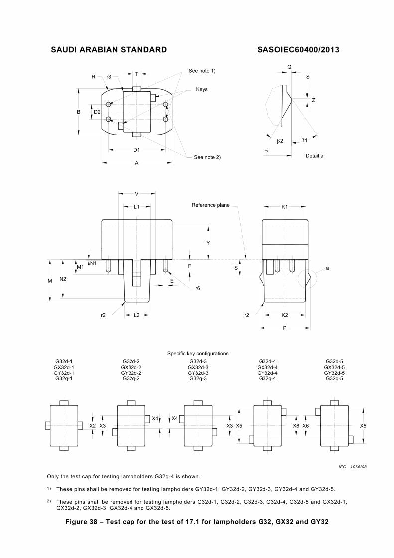
SAUDI ARABIAN STANDARD SASOIEC60400/2013
E
F
Y
N2M
r2 K2
S
r2
a
Q
Z
P
12
Reference plane
Detail aSee note 2)
r6
P
V
D1
A
TSee note 1)
Keys
B
M1N1
X5 X6 X6 X5
X4
X3
X4
X3X2
Specific key configurations
G32d-1GX32d-1GY32d-1G32q-1
G32d-2GX32d-2GY32d-2G32q-2
G32d-3GX32d-3GY32d-3G32q-3
G32d-4GX32d-4GY32d-4G32q-4
G32d-5GX32d-5GY32d-5G32q-5
K1
SR r3
D2
L1
L2
Only the test cap for testing lampholders G32q-4 is shown.
1) These pins shall be removed for testing lampholders GY32d-1, GY32d-2, GY32d-3, GY32d-4 and GY32d-5.
2) These pins shall be removed for testing lampholders G32d-1, G32d-2, G32d-3, G32d-4, G32d-5 and GX32d-1, GX32d-2, GX32d-3, GX32d-4 and GX32d-5.
Figure 38 – Test cap for the test of 17.1 for lampholders G32, GX32 and GY32
IEC 1066/08

SAUDI ARABIAN STANDARD SASOIEC 60400/2013
75
Reference Dimension
mm Tolerance
mm
A 38 0,02
B 23,6 0,02
D1 31,0 0,01
D2 8,0 0,01
E 2,54 0,02
F 6,8 0,02
K1* 21,95 0,02
K2** 21,2 0,02
L1* 16,35 0,02
L2** 15,6 0,02
M 26,5 + 0,02 – 0,05
M1 8,0 + 0,02 – 0,05
N1 0,5 –
N2 24,5 –
P 26,7 0,02
Q 1,2 0,02
R B/2 –
S 9,0 0,05
T 4,5 0,02
V 21,2 0,01
X2 3,6 0,01
X3 11,1 0,01
X4 3,9 0,01
X5 18,6 0,01
X6 11,4 0,01
Y 18 0,2
Z 0,5 0,05
r2 0,8 0,05
r3 0,5 0,05
r6 E/2 –
1 35° 1°
2 30° 1°
* Measured at distance N1.
** Measured at distance N2.
Figure 38 (continued)

SAUDI ARABIAN STANDARD SASOIEC60400/2013
H
R
R
A A11
2
U
D1
D
K
E
FJ
N
The drawing is intended only to illustrate the essential dimensions of the gauge.
Reference Dimension
mm Tolerance
mm
A 59,5 0,02
A1 53,7 0,02
D 7,5 0,01
D1 32,5 0,01
E 2,37 0,01
F 6,4 0,02
H 14,5 0,02
J 0,4 0,02
K 10,2 0,02
N 65,0 0,02
R 1,0 0,02
U 2,35 0,02
α1 9° 10´
α2 8° 10´
β 30° 1°
Figure 39 – Test cap for the test of Clause 13 for lampholders 2G8
IEC 1067/08
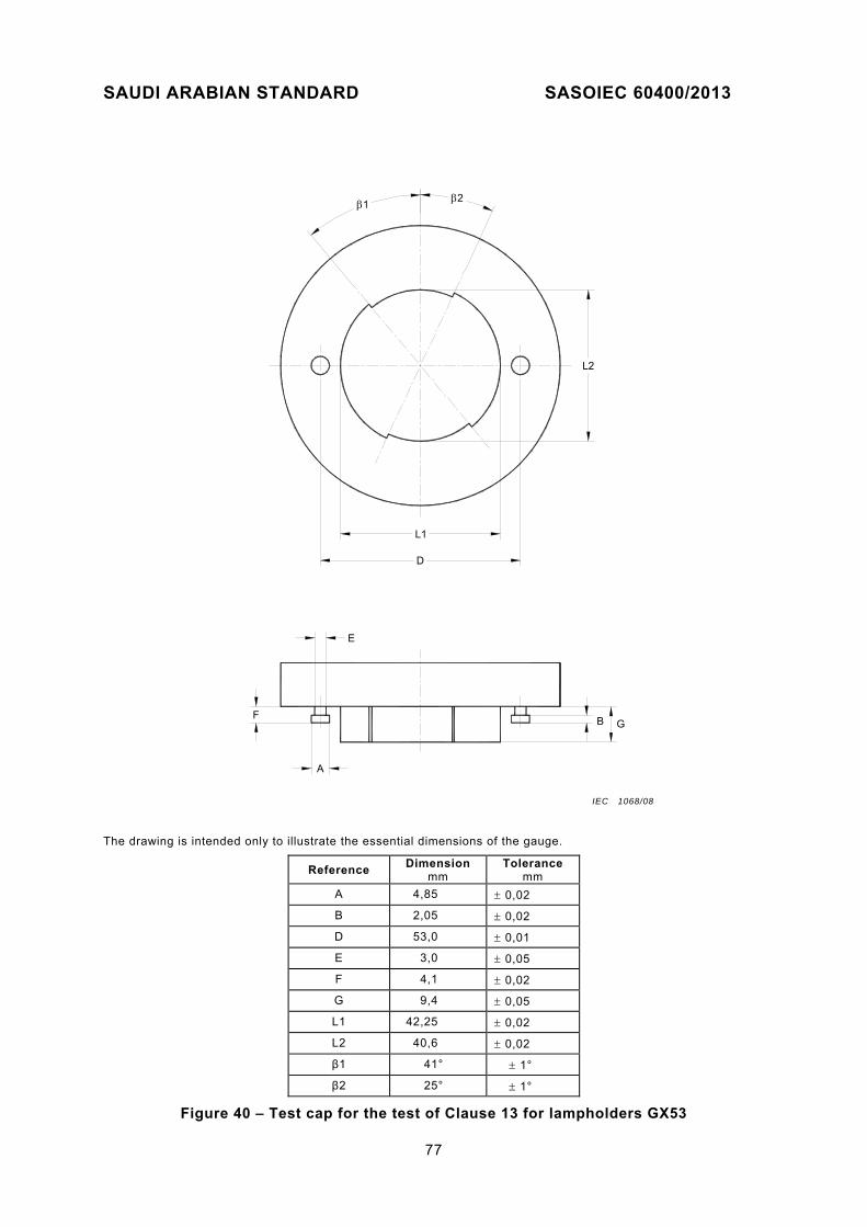
SAUDI ARABIAN STANDARD SASOIEC 60400/2013
77
F
E
A
B G
D
L2
L1
21
The drawing is intended only to illustrate the essential dimensions of the gauge.
Reference Dimension
mm Tolerance
mm
A 4,85 0,02
B 2,05 0,02
D 53,0 0,01
E 3,0 0,05
F 4,1 0,02
G 9,4 0,05
L1 42,25 0,02
L2 40,6 0,02
β1 41° 1°
β2 25° 1°
Figure 40 – Test cap for the test of Clause 13 for lampholders GX53
IEC 1068/08

SAUDI ARABIAN STANDARD SASOIEC60400/2013
Linear dimensions in millimetres
Ø 50
20±0,2
Ø 75
37°
A
B B
A
10
14°
2030
60
80
180
5±0,5
Section A-A
Section B-B
R=2±0,05Cylindrical
R=4±0,05Spherical
Handle
Guard
Insulating material
Stop face
Joints
Ø12Chamfer alledges
Material: metal, except where otherwise specified
Tolerances on dimensions without specific tolerance:
– on angles: 0
01
– on linear dimensions:
up to 25 mm:0
050 ,
over 25 mm: 0,2 mm
Both joints shall permit movement in the same plane and the same direction through an angle of 90° with a 0° to +10° tolerance.
Figure 41 – Standard test finger (according to IEC 60529)
IEC 1069/08
SAUDI ARABIAN STANDARD SASOIEC 60400/2013
79
Annex A (normative)
Examples of lampholders covered by this standard
(This list is not exhaustive.)
Independent and built-in lampholders used with tubular fluorescent lamps provided with the caps listed below are covered by this standard (see the scope, second paragraph).
Lampholder Lampholder sheet
(see IEC 60061-2)
G5
2G8
GR8
G10q
GR10q
GRZ10d
GRZ10t
GU10q
GX10q
GY10q
GZ10q
2G11
G13
2G13
2GX13
G20
G23
GX23
G24, GX24, GY24
G32, GX32, GY32
GX53
Fa6
Fa8
R17d
7005-51
7005-141
7005-68
7005-56
7005-77
7005-131
7005-132
7005-123
7005-84
7005-85
7005-124
7005-82
7005-50
7005-33
7005-125
7005-.. (under consideration)
7005-69
7005-86
7005-78
7005-87
7005-142
7005-55
7005-58
7005-57

SAUDI ARABIAN STANDARD SASOIEC60400/2013
Annex B
(normative)
Season cracking/corrosion test
B.1 Test cabinet
Closeable glass vessels shall be used for the test. These may be, for example, desiccator vessels or simple glass troughs with a ground rim and lid. The vessel volume shall be at least 10 l. A certain ratio of test space to volume of test solution shall be maintained (20:1 to 10:1).
B.2 Test solution
NOTE 1 In the interest of environmental protection, the following requirements relating to the test solution, its volume and the volume of the vessel may be modified at the discretion of the test laboratory.
In this event, the test vessel should retain a volume in the range 500 to 1 000 times larger than the volume of the sample and the volume of the test solution should be such that the ratio of vessel volume to solution volume is in the range of 20:1 to 10:1.
NOTE 2 In case of doubt, however, the conditions of Clause B.1 apply.
Preparation of 1 l of solution:
Dissolve 107 g of ammonium chloride (reagent grade NH4Cl) in about 0,75 l of distilled or fully demineralized water and add as much of 30 % sodium hydroxide solution (prepared from reagent grade NaOH and distilled or fully demineralized water) as is necessary to reach a pH value of 10 at 22 °C. For other temperatures, adjust this solution to the corresponding pH values specified in Table B.1.
Table B.1 – pH adjustment
Temperature
°C
Test solution
pH
22 1
25 1
27 1
30 1
10,0 0,1
9,9 0,1
9,8 0,1
9,7 0,1
After the pH adjustment, make up to 1 l with distilled or fully demineralized water.
This does not change the pH value any more.
Keep the temperature in any event constant to within 1 °C during the pH adjustment and carry out the pH measurement using an instrument which permits an adjustment of the pH value to within 0,02.
The test solution may be used over a prolonged period, but the pH value, which represents a measure of the ammonia concentration in the vapour atmosphere, shall be checked at least every three weeks and adjusted if necessary.

SAUDI ARABIAN STANDARD SASOIEC 60400/2013
81
B.3 Test procedure
Introduce, and preferably suspend, the specimens in the test cabinet in such a way that the ammonia vapour can take effect unhindered.
The specimens shall not dip into the test solution nor touch each other.
Supports or suspension devices shall be made of materials which are not susceptible to be attacked by ammonia vapour, such as glass or porcelain.
Testing shall be carried out at a constant temperature of 30 °C 1 °C to exclude visible condensed water formation caused by temperature fluctuations, which could severely falsify the test result.
Prior to testing, the test cabinet containing the test solution shall be brought to a temperature of 30 °C 1 °C. The test cabinet shall subsequently be filled as quickly as possible with the specimens pre-heated to 30 °C and closed. This moment is to be considered as the beginning of the test.

SAUDI ARABIAN STANDARD SASOIEC60400/2013
Annex C
(informative)
Protection against electric shock – Explanatory details for the installation
of lampholders according to 8.2
Figure C.1 Figure C.2
Figure C.3 Figure C.4
Figure C.1 to C.4 – Examples of lampholders
IEC 1069/08IEC 1070/08 IEC 1071/08
IEC 1072/08 IEC 1073/08

SAUDI ARABIAN STANDARD SASOIEC 60400/2013
83
Bibliography
IEC 60061-4, Lamp caps and holders together with gauges for the control of interchangeability and safety – Part 4: Guidelines and general information
___________