Embed Size (px)
Citation preview

1Narda-MITEQ
S AT C O M F I B E R - O P T I C P R O D U C T S
One Third Rack
C-Band LNACard Cage Rack
DC-Powered L-Band Link
S-Band LNAAC-PoweredKu-Band Link Ku-Band LNA
ADVANTAGES OF FIBER-OPTICS
• Longer transmission paths than coaxial cable
• Easy installation, lightweight and flexible
• Fiber is unsusceptible to lightning strikes
• Provides EMI/RFI insulation
• Larger bandwidths
Indoor Applications
Outdoor Applications
TABLE OF CONTENTSINDOOR EQUIPMENT PAGEOne third rack links 2
One third rack RSU 3
Card cage links 4 and 5
Link specifications 6 and 7
RSU specifications 8 and 9
Outline drawings 16
Options 18 and 19
OUTDOOR EQUIPMENT PAGEDC-powered L-Band links 10
AC-powered links 11
Specifications 12 and 13
Integrated LNAs 14 and 15
Outline drawings 16 and 17
Options 18 and 19
2 Narda-MITEQ
S AT C O M F I B E R - O P T I C P R O D U C T S
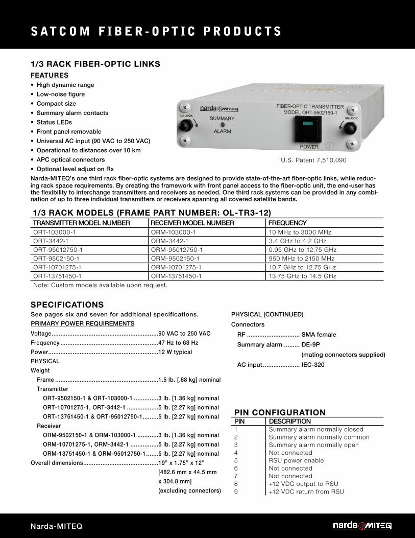
1/3 RACK FIBER-OPTIC LINKS
SPECIFICATIONS
PIN CONFIGURATIONPIN DESCRIPTION1 Summary alarm normally closed2 Summary alarm normally common3 Summary alarm normally open4 Not connected5 RSU power enable 6 Not connected7 Not connected8 +12 VDC output to RSU9 +12 VDC return from RSU
1/3 RACK MODELS (FRAME PART NUMBER: OL-TR3-12)TRANSMITTER MODEL NUMBER RECEIVER MODEL NUMBER FREQUENCYORT-103000-1 ORM-103000-1 10 MHz to 3000 MHzORT-3442-1 ORM-3442-1 3.4 GHz to 4.2 GHzORT-95012750-1 ORM-95012750-1 0.95 GHz to 12.75 GHzORT-9502150-1 ORM-9502150-1 950 MHz to 2150 MHzORT-10701275-1 ORM-10701275-1 10.7 GHz to 12.75 GHzORT-13751450-1 ORM-13751450-1 13.75 GHz to 14.5 GHzNote: Custom models available upon request.
FEATURES
ing rack space requirements. By creating the framework with front panel access to the fiber-optic unit, the end-user has the flexibility to interchange transmitters and receivers as needed. One third rack systems can be provided in any combi-nation of up to three individual transmitters or receivers spanning all covered satellite bands.
See pages six and seven for additional specifications.
PRIMARY POWER REQUIREMENTS
Voltage .............................................................90 VAC to 250 VAC
Frequency ........................................................47 Hz to 63 Hz
Power ...............................................................12 W typical
PHYSICAL
Weight
Frame ...........................................................1.5 lb. [.68 kg] nominal
Transmitter
ORT-9502150-1 & ORT-103000-1 ..............3 lb. [1.36 kg] nominal
ORT-10701275-1, ORT-3442-1 ..................5 lb. [2.27 kg] nominal
ORT-13751450-1 & ORT-95012750-1 .........5 lb. [2.27 kg] nominal
Receiver
ORM-9502150-1 & ORM-103000-1 ............3 lb. [1.36 kg] nominal
ORM-10701275-1, ORM-3442-1 ................5 lb. [2.27 kg] nominal
ORM-13751450-1 & ORM-95012750-1 .......5 lb. [2.27 kg] nominal
Overall dimensions ...........................................19” x 1.75” x 12”
[482.6 mm x 44.5 mm
x 304.8 mm]
(excluding connectors)
PHYSICAL (CONTINUED)
Connectors
RF .............................. SMA female
Summary alarm ......... DE-9P
(mating connectors supplied)
AC input ..................... IEC-320
U.S. Patent 7,510,090
• High dynamic range
• Low-noise figure
• Compact size
• Summary alarm contacts
• Status LEDs
• Front panel removable
• Universal AC input (90 VAC to 250 VAC)
• Operational to distances over 10 km
• APC optical connectors
• Optional level adjust on Rx
Narda-MITEQ’s one third rack fiber-optic systems are designed to provide state-of-the-art fiber-optic links, while reduc-

3
1/3 RACK FIBER REDUNDANT SWITCHOVER UNIT
ADDITIONAL INFORMATION
OPTIONS AND NOTES
1/3 RACK MODELS (FRAME PART NUMBER: OL-TR3-12)MODEL* RF SWITCHING FIBER SWITCHING FIBER CONNECTOR TYPEOSU-S-TR X N/A
OSU-FC-TR X FC/APC
OSU-E-TR X E2000/APC
OSU-SC-TR X SC/APC
OSU-S/FC-TR X X FC/APC
OSU-S/E-TR X X E2000/APC
OSU-S/SC-TR X X SC/APC* See page two for available one third rack transmitters and receivers. All transmitter and receiver units ordered prior to
June 2006 need to be retrofitted before accommodating switchover system.
FEATURES• RF and optical switching
• Local and remote control (RS-485/RS-422 10/100 Base-T Ethernet)
• Automatic/manual control from both local and remote control
• Remote status
• Off-line input
• APC optical connectors
• CE mark
The 1:1 redundant switchover unit is used with two one third rack fiber-optic units, one on-line (Unit A) and the second in standby mode (Unit B). A fault condition in the on-line unit A, or an operator-generated command will switch the standby Unit B to the on-line position and remove Unit A from the transmission path. A full-feature set of commands is available for both remote and local control.
The 1:1 redundant switchover unit is designed to ensure continuous operation allowing a unit fault to be repaired and/or routine maintenance to be performed without disruption of signal transmission.
The 1:1 redundant switchover unit can be ordered as an RF, fiber or a combination of RF and fiber switching system.
See pages eight and nine for a list of additional specifications.
See pages 18 and 19 for a list of additional options.
U.S. Patent 7,510,090
For literature describing local control (front panel) and remote control (remote bus), refer to Narda-MITEQ Technical Note 25T067.
1:2 switchover available using NSU2 controller. See Narda-MITEQ data sheet D-323 for details.

4 Narda-MITEQ
S AT C O M F I B E R - O P T I C P R O D U C T S
CARD CAGE FIBER-OPTIC LINKS
CARD CAGE COMPONENTSMODEL NUMBER DESCRIPTIONOCC-1 Card Cage Rack
PS-OCC-1* Power Supply
PS-OCC-2* Power Supply
* Card cage can operate from a single-power supply, however, two power supplies are needed for redundancy.
CARD CAGE MODELSTRANSMITTER MODEL NUMBER RECEIVER MODEL NUMBER FREQUENCYOCCT-103000-1 OCCR-103000-1 10 MHz to 3000 MHz
OCCT-9502150-1 OCCR-9502150-1 950 MHz to 2150 MHz
OCCT-3442-1* OCCR-3442-1 3.4 GHz to 4.2 GHz
OCCT-95012750-1* OCCR-95012750-1 0.95 GHz to 12.75 GHz
OCCT-10701275-1* OCCR-10701275-1 10.7 GHz to 12.75 GHz
OCCT-13751450-1* OCCR-13751450-1 13.75 GHz to 14.5 GHz
Note: Custom models available upon request. * Denotes double width models.
FEATURES• High dynamic range
• Low-noise figure
• Hot-swappable modules
• Diode-summed power supplies
• Ten module capacity in a two rack unit high chassis
• Summary alarm contacts for each module
• Status LEDs
• Front panel removable
• Universal AC input (90 VAC to 250 VAC)
• Operational to distances over 10 km
• APC optical connectors
Narda-MITEQ’s fiber-optic card cage system provides support for multiple transmitter and receiver modules spanning all covered satellite bands. The card cage design allows for the availability of multiple fiber-optic links in a two-rack unit high chassis, featuring hot-swappable connections, diode-summed redundant power supplies and summary alarm con-tacts. The card cage can be configured with up to ten receiver modules, five transmitter modules, or any combination of up to ten L-Band transmitter and/or receiver modules.

5
CARD CAGE FIBER-OPTIC LINKS SPECIFICATIONS
OPTIONS
See pages six and seven for additional specifications.
PRIMARY POWER REQUIREMENTS
Voltage ............................................................. 90 VAC to 250 VAC
Frequency ........................................................ 47 Hz to 63 Hz
Power
PS-OCC-1 ..................................................... 45 W maximum
PS-OCC-2 ..................................................... 150 W maximum
PHYSICAL
Weight
Transmitter ................................................... 3 lb. [1.36 kg] nominal
Receiver ........................................................ 2 lb. [.91 kg] nominal
Card cage ..................................................... 4 lb. [1.82 kg] nominal
Power supply ................................................ 3 lb. [1.36 kg] nominal
Overall dimensions .......................................... 19” x 3.5” x 10” [482.6 mm x 88.9 mm x 254 mm]
(excluding connectors)
Connectors
RF ................................................................. SMA female
Summary alarm ............................................ DB-25S
AC input ........................................................ IEC-320
Optical .......................................................... See page seven
See pages 18 and 19 for a list of additional options.

6 Narda-MITEQ
S AT C O M F I B E R - O P T I C P R O D U C T S
SPECIFICATIONS FOR INDOOR FIBER-OPTIC LINKS
ELECTRICAL SPECIFICATIONSBAND L-BAND L- AND S-BAND C-BANDThird rack model numbers ORT-9502150-1, ORM-9502150-1 ORT-103000-1, ORM-103000-1 ORT-3442-1, ORM-3442-1
Card cage model numbers OCCT-9502150-1, OCCR-9502150-1 OCCT-103000-1, OCCR-103000-1 OCCT-3442-1, OCCR-3442-1
Frequency range 950 MHz to 2150 MHz 10 MHz to 3000 MHz 3.4 GHz to 4.2 GHz
Gain 5 dB typical 10 dB minimum 10 dB typical
Amplitude response 1.5 dB peak-to-peak maximum 1.5 dB peak-to-peak maximum ±1 dB peak-to-peak maximum
Noise Figure 20 dB typical 10 dB typical, 15 dB maximum (above 10 MHz)
20 dB maximum
Group delay ±0.1 ns peak-to-peak ±0.1 ns peak-to-peak ±0.1 ns peak-to-peak
Input power (1 dB compression point)
-14 dBm minimum -14 dBm minimum -15 dBm minimum
Third-order intermodulation with two -25 dBm inputs
-42 dBc -42 dBc -40 dBc
Gain stability ±0.25 dB/24 hours at constant temperature
±0.25 dB/24 hours at constant temperature
±0.25 dB/24 hours at constant temperature
VSWR (RF only) 2.0:1 maximum 2.0:1 maximum 1.2:1 maximum
RF impedance 50 ohms 50 ohms 50 ohms
Phase noise* -100 dBc/Hz typical at 100 Hz offset -100 dBc/Hz typical at 100 Hz offset -100 dBc/Hz typical at 100 Hz offset
Spurious-free dynamic range 100 dB minimum at 1 Hz bandwidth 100 dB minimum at 1 Hz bandwidth 100 dB minimum at 1 Hz bandwidth
Non-damage input +10 dBm +10 dBm +5 dBm
* Phase noise is residual phase noise not single sideband. Specification is guaranteed not measured.
ELECTRICAL SPECIFICATIONSBAND BROADBAND Ku-BAND (Rx-BAND) Ku-BAND (Tx-BAND)Third rack model numbers ORT-95012750-1, ORM-95012750-1 ORT-10701275-1, ORM-10701275-1 ORT-13751450-1, ORM-13751450-1
Card cage model numbers OCCT-95012750-1, OCCR-95012750-1 OCCT-10701275-1, OCCR-10701275-1 OCCT-13751450-1, OCCR-13751450-1
Frequency range 0.95 GHz to 12.750 GHz 10.70 GHz to 12.75 GHz 13.75 GHz to 14.5 GHz
Gain 13 dB typical 10 dB typical 10 dB typical
Amplitude response ±4 dB peak-to-peak maximum ±2 dB peak-to-peak maximum ±2 dB peak-to-peak maximum
Noise figure 20 dB typical, 25 dB maximum 20 dB typical, 25 dB maximum 20 dB typical, 25 dB maximum
Group delay ±0.1 ns peak-to-peak ±0.1 ns peak-to-peak ±0.1 ns peak-to-peak
Input power (1 dB compression point)
-15 dBm minimum -15 dBm minimum -15 dBm minimum
Third-order intermodulation with two -25 dBm inputs
-40 dBc -40 dBc -40 dBc
Gain stability ±0.25 dB/24 hours at constant temperature
±0.25 dB/24 hours at constant temperature
±0.25 dB/24 hours at constant temperature
VSWR (RF only) 2.0:1 maximum 1.3:1 maximum 1.3:1 maximum
RF impedance 50 ohms 50 ohms 50 ohms
Phase noise* -100 dBc/Hz typical at 100 Hz offset -100 dBc/Hz typical at 100 Hz offset -100 dBc/Hz typical at 100 Hz offset
Spurious-free dynamic range 100 dB minimum at 1 Hz bandwidth 100 dB minimum at 1 Hz bandwidth 100 dB minimum at 1 Hz bandwidth
Non-damage input +5 dBm +5 dBm +5 dBm
* Phase noise is residual phase noise not single sideband. Specification is guaranteed not measured.
The following specifications are based on link data, with 1 dB of optical loss and -30 dBm input level.

7
SPECIFICATIONS FOR INDOOR FIBER-OPTIC LINKS (CONTINUED)
FUNCTIONAL BLOCK DIAGRAM
OPTICAL SPECIFICATIONSFiber 9/125 (single-mode fiber)
Optical connector*
L- and S-Band units FC/APC
C- and Ku-Band units E2000/APC
Wavelength**
Minimum 1300 nm (receivers), 1540 nm (transmitters)
Typical 1550 nm
Maximum 1560 nm
COMMON ENVIRONMENTAL SPECIFICATIONSOperating Ambient temperature ................................... 0 °C to 50 °C Relative humidity .......................................... Up to 95% at 30 °C Atmospheric pressure .................................. Up to 10,000 feetNonoperating Ambient temperature ................................... -30 °C to +60 °C Relative humidity .......................................... Up to 95% at 40 °C Atmospheric pressure .................................. Up to 40,000 feet Shock and vibration ..................................... Normal handling by commercial carriers
RFINPUT
OPTICALCABLE
LNA(PRE-
AMPLIFIER)
ISOLATOR
C- & Ku-BANDONLY
C- & Ku-BANDONLY
LNA
PHOTODIODE
TRANS-IMPEDANCEAMPLIFIER
TRANS-IMPEDANCEAMPLIFIER
OPTION2
OPTION2
RFOUTPUT
RFINPUT
OPTICALCABLE
LNA(PRE-
AMPLIFIER)
ISOLATOR
C- & Ku-BANDONLY
C- & Ku-BANDONLY
LNA
PHOTODIODE
TRANS-IMPEDANCEAMPLIFIER
TRANS-IMPEDANCEAMPLIFIER
RFOUTPUT
RFINPUT
OPTICALOUTPUT
-22 dBc
ISOLATOR
LNA
TRANS-IMPEDANCEAMPLIFIER
RFOUTPUT
Spectral width 1.0 nm (transmitter only)
Optical power in fiber 4 mW typical
Single side-mode suppression ratio 30 dB minimum, 40 dB typical
* Optical connectors are standard connectors for listed bands. Other connectors are available as an option.
** Wavelengths listed are Narda-MITEQ’s standard. For cases where a CWDM (Coarse Wavelength Division Multiplexing) system is needed, Narda-MITEQ can supply up to 10 dif ferent transmitter wavelengths with 20 nm channel spacing.

8 Narda-MITEQ
S AT C O M F I B E R - O P T I C P R O D U C T S
SPECIFICATIONS FOR 1/3 RACK SWITCHOVER UNITS
FUNCTIONAL BLOCK DIAGRAM
MODES OF OPERATIONS Local mode ...................................................Commands are received from the keys on the front-panel. Remote mode ...............................................Commands are received from a remote system controller via the remote interface connector. All front-panel keys are disabled, with the exception of local/remote mode selection. Automatic mode ...........................................Switchover occurs if a fault is detected in an on-line unit. Manual mode ................................................Switchover may be executed either via the front panel keys (local mode) or the remote interface (remote mode).
MODES OF OPERATIONS Switch type ................................................... Coaxial, four-port transfer Switch contacts ............................................ Break-before-make, wiping Switch drive .................................................. Latching Switching speed ........................................... 150 ms maximum
OPTICAL SWITCH SPECIFICATIONS Switch type ................................................... Optical, 2 x 2 Switch drive .................................................. Latching Switching speed ........................................... 10 ms maximum
RF SPECIFICATIONSFREQUENCY VSWR (MAXIMUM) ISOLATION (MINIMUM) INSERTION LOSS (TYPICAL)DC to 1 GHz 1.10:1 85 dB 0.40 dB
1 GHz to 4 GHz 1.20:1 80 dB 0.45 dB
4 GHz to 8 GHz 1.30:1 70 dB 0.55 dB
8 GHz to 14.5 GHz 1.40:1 65 dB 0.65 dB
OPTICAL SPECIFICATIONSFREQUENCY VSWR (MAXIMUM) ISOLATION (MINIMUM) INSERTION LOSS (TYPICAL)DC to 14.5 GHz 1.01:1 60 dB 1.0 dB
REDUNDANCY ALARMINTERFACE CABLE
REDUNDANCY ALARMINTERFACE CABLE
J7
J7
J3 J4UNIT
A
UNITB RF
SWITCH
J4A
OPTICALSWITCH
ON-LINEFIBER
ON-LINERF
ON-LINE“A”
ON-LINE“B”
OFF-LINEFIBER
OFF-LINERFJ3A
J1 J2
J5J6
J6A
UNITA
ON-LINE“A”
ON-LINE“B”
STANDBYPATH
UNITC
UNITB
J5A
J1J2
J2A
RF OR OPTICALSWITCHES
REDUNDANCY ALARMINTERFACE CABLE
REDUNDANCY ALARMINTERFACE CABLE
REDUNDANCY ALARMINTERFACE CABLE
STANDBYPATH
J1A
21
43
21
43
21
43
21
43
J2A J1A

9
SPECIFICATIONS FOR 1:1 SWITCHOVER UNITS
1/3 RACK SPECIFICATIONSPRIMARY POWER REQUIREMENT
Voltage ............................DC power from Narda-MITEQ
1/3 rack fiber-optic Tx and Rx
PHYSICAL
Dimensions (excluding connectors)
Module .........................5.70” x 1.48” x 12”
[144.78 mm x 37.59 mm
x 304.8 mm]
Frame ...........................19” x 1.75” panel height x 12”
[482.60 mm x 44.45 mm
x 304.8 mm]
Weight
Module .........................4.5 lb. [2.04 kg] nominal
Frame ...........................1.5 lb. [0.68 kg] nominal
Connectors
RF ................................SMA female
Fiber optic ....................FC/APC, or E2000/APC
or SC/APC
Redundancy alarm* ......DE-15P
Remote interface* .........DE-9S for RS-422/RS-485
Ethernet interface .........RJ-45
* Mating connectors supplied.
REDUNDANCY CONNECTOR J7PIN Description1 Unit A summary alarm normally open
2 Unit A summary alarm common
3 Unit A summary alarm normally closed
5 Unit A +12 VDC
7 Unit A +12 VDC return
9 Unit B summary alarm normally open
10 Unit B summary alarm common
11 Unit B summary alarm normally closed
13 Unit B +12 VDC
15 Unit B +12 VDC return
REDUNDANCY CONNECTOR J6PIN Description1 Ground
2 OSU summary alarm common
3 Data out-
4 OSU summary alarm open
5 Data in-
6 OSU summary alarm closed
7 Data out+
8 Not connected
9 Data in+n

10 Narda-MITEQ
S AT C O M F I B E R - O P T I C P R O D U C T S
DC-POWERED OUTDOOR L-BAND FIBER-OPTIC LINKS
SPECIFICATIONS
OPTIONS
PIN CONFIGURATIONPIN DESCRIPTION1 Ground2 +15 VDC input3 Not connected4 Summary alarm normally closed5 Summary alarm common6 Summary alarm normally open7 Not connected8 Not connected9 Not connected
TRANSMITTER AND RECEIVER MODELSTRANSMITTER MODEL NUMBER RECEIVER MODEL NUMBER FREQUENCYOWT-103000-1* OWR-103000-1* 10 MHz to 3000 MHz
OWT-9502150-1 OWR-9502150-1 950 MHz to 2150 MHz
* Extended frequency range available, see Options.
FEATURES• High dynamic range
• Low-noise figure
• Operational to distances over 60 km
• Compact size
• Weather-tight enclosure
• Summary alarm contacts
• Status LEDs
See pages twelve and thirteen for additional specifications.
PRIMARY POWER REQUIREMENTS
Voltage .......................................... +15 ±0.5 VDC
Noise ripple ................................... < 100mV peak-to-peak
Power
Transmitter ................................ 7.5 W typical
Receiver ..................................... 4.5 W typical
Available colors
Furniture white (standard) ......... FED-STD-595B color 27875
Monarch black ........................... FED-STD-595B color 27038
Green PMS 383.......................... FED-STD-595B color 34094
Desert tan .................................. FED-STD-595B color 33303
PHYSICAL
Weight ........................................... 2 lb. [.91 kg] nominal
Overall dimensions ....................... 5.0” x 3.25” x 1.3”
[127 mm x 82.55 mm x 33.02 mm]
Connectors
RF .............................................. SMA female
Optical ....................................... FC/APC (ST/APC optional)
Alarm/power .............................. DE-9P (mating connector supplied)
See pages 18 and 19 for a list of additional options.
Narda-MITEQ’s outdoor L-Band fiber-optic links are designed for antenna mounting. With a high dynamic range and low-noise figure these units provide a low-cost alternative to coaxial cable. Their compact size provide an ideal solution for L-Band antenna-based fiber-optic applications.

11
SPECIFICATIONS
OPTIONS
AC-POWERED OUTDOOR FIBER-OPTIC LINKS
PIN CONFIGURATIONPIN DESCRIPTION1 Ground2 Not connected3 Summary alarm normally closed4 Summary alarm common5 Not connected6 LNA output voltage (optional)7 Not connected8 Summary alarm common9 Not connected
TRANSMITTER AND RECEIVER MODELSTRANSMITTER MODEL NUMBER RECEIVER MODEL NUMBER FREQUENCYOWT-103000-2 OWR-103000-2 10 MHz to 3000 MHz
OWT-9502150-2 OWR-9502150-2 950 MHz to 2150 MHz
OWT-3442-2 OWR-3442-2 3.4 GHz to 4.2 GHz
OWT-95012750-2 OWR-95012750-2 0.95 GHz to 12.75 GHz
OWT-10701275-2 OWR-10701275-2 10.7 GHz to 12.75 GHz
OWT-13751450-2 OWR-13751450-2 13.75 GHz to 14.5 GHz
FEATURES• High dynamic range
• Low-noise figure
• Operational to distances over 10 km
• Compact size
• Weather-tight enclosure
• Summary alarm contacts
• Status LEDs
• Universal AC input (90 VAC to 250 VAC)
• Optional DC output to LNA
• CE mark
See pages 12 and 13 for additional specifications.PRIMARY POWER REQUIREMENTSVoltage ...................................... 90 VAC to 250 VACFrequency ................................. 47 Hz to 63 HzPower* Transmitter ............................ 12 W typical Receiver ................................. 8 W typical* Without LNA option.LNA Optional PowerVoltage ...................................... +12 VDCCurrent ...................................... 500 mA maximumAvailable colors Furniture white (standard) ..... FED-STD-595B color 27875 Monarch black ....................... FED-STD-595B color 27038 Green PMS 383...................... FED-STD-595B color 34094 Desert tan .............................. FED-STD-595B color 33303PHYSICALWeight ....................................... 6 lb. [2.72 kg] nominalOverall dimensions ................... 7.34” x 5.0” x 2.78” [186.44 mm x 127 mm x 70.61 mm]
PHYSICAL (CONTINUED)Connectors RF ............................SMA female Optical ..................... FC/APC (ST/APC optional) AC input ..................MS3102R10SL-3P (mating connector supplied) Alarm/power ............DE-9P (mating connector supplied)
See pages 18 and 19 for a list of additional options.
Narda-MITEQ’s outdoor AC-powered fiber-optic links are designed for antenna mounting. With a high dynamic range and low-noise figure these units provide a low-cost alternative to coaxial cable. These units are an alternative to Narda-MITEQ’s DC-powered units. These units are available in all covered satellite bands and are an ideal solution for all an-tenna-based fiber-optic applications.

12 Narda-MITEQ
S AT C O M F I B E R - O P T I C P R O D U C T S
SPECIFICATIONS FOR OUTDOOR FIBER-OPTIC LINKS
ELECTRICAL SPECIFICATIONSBAND L-BAND L- AND S-BAND C-BANDModel number OWT-9502150-1, OWR-9502150-1 OWT-103000-1, OWR-103000-1 OWT-3442-2, OWR-3442-2
OWT-9502150-2, OWR-9502150-2 OWT-103000-2, OWR-103000-2
Frequency range 950 to 2150 MHz 10 to 3000 MHz 3.4 to 4.2 GHz
Gain 5 dB nominal 10 dB nominal 10 dB nominal
Amplitude response 1.5 dB peak-to-peak maximum 1.5 dB peak-to-peak maximum ±1 dB peak-to-peak maximum
Noise figure 20 dB typical 10 dB typical, 15 dB maximum (above 10 MHz)
20 dB maximum
Group delay ±0.1 ns peak-to-peak ±0.1 ns peak-to-peak ±0.1 ns peak-to-peak
Input power (1 dB compression point)
-14 dBm minimum -14 dBm minimum -15 dBm minimum
Third-order intermodulation with two -25 dBm inputs
-42 dBc -42 dBc -40 dBc
Gain stability ±0.25 dB/24 hours at constant temp. ±0.25 dB/24 hours at constant temp. ±0.25 dB/24 hours at constant temp.
±5 dB/temperature range ±5 dB/temperature range ±5 dB/temperature range
VSWR (RF only) 2.0:1 maximum 2.0:1 maximum 1.2:1 maximum
RF impedance 50 ohms 50 ohms 50 ohms
Phase noise* -100 dBc/Hz typical at 100 Hz offset
-100 dBc/Hz typical at 100 Hz offset
-100 dBc/Hz typical at 100 Hz offset
Spurious-free dynamic range
100 dB minimum at 1 Hz bandwidth
100 dB minimum at 1 Hz bandwidth
100 dB minimum at 1 Hz bandwidth
Non-damage input +10 dBm +10 dBm +5 dBm
* Phase noise is residual phase noise not single sideband. Specification is guaranteed not measured.
ELECTRICAL SPECIFICATIONSBAND BROADBAND Ku-BAND (Rx-BAND) Ku-BAND (Tx-BAND)Model number OWT-95012750-2, OWT-10701275-2, OWT-13751450-2,
OWR-95012750-2 OWR-10701275-2 OWR-13751450-2
Frequency range 0.95 GHz to 12.750 GHz 10.70 GHz to 12.75 GHz 13.75 GHz to 14.5 GHz
Gain 13 dB typical 10 dB typical 10 dB typical
Amplitude response ±4 dB peak-to-peak maximum ±2 dB peak-to-peak maximum ±2 dB peak-to-peak maximum
Noise figure 25 dB maximum 25 dB maximum 25 dB maximum
Group delay ±0.1 ns peak-to-peak ±0.1 ns peak-to-peak ±0.1 ns peak-to-peak
Input power (1 dB compression point)
-15 dBm minimum -15 dBm minimum -15 dBm minimum
Third-order intermodulation with two -25 dBm inputs
-40 dBc -40 dBc -40 dBc
Gain stability ±0.25 dB/24 hours at constant temp. ±0.25 dB/24 hours at constant temp. ±0.25 dB/24 hours at constant temp.
±5 dB/temperature range ±5 dB/temperature range ±5 dB/temperature range
VSWR (RF only) 2.0:1 maximum 1.3:1 maximum 1.3:1 maximum
RF impedance 50 ohms 50 ohms 50 ohms
Phase noise* -100 dBc/Hz typical at 100 Hz offset -100 dBc/Hz typical at 100 Hz offset -100 dBc/Hz typical at 100 Hz offset
Spurious-free dynamic range
100 dB minimum at 1 Hz bandwidth 100 dB minimum at 1 Hz bandwidth 100 dB minimum at 1 Hz bandwidth
Non-damage input +5 dBm +5 dBm +5 dBm
* Phase noise is residual phase noise not single sideband. Specification is guaranteed not measured.
The following specifications are based on link data, with 1 dB of optical loss and -30 dBm input level.

13
SPECIFICATIONS FOR OUTDOOR FIBER-OPTIC LINKS (CONTINUED)
Missing option numbers are not applicable for this product.
4. DC output to LNA for AC-powered units
A. DC output on J3 connector to power LNA
+12 VDC available at 500 mA maximum
B. DC output on RF center pin to power LNA
+12 VDC available at 300 mA maximum
See pages 18 and 19 for a list of available options.
OPTIONS
FUNCTIONAL BLOCK DIAGRAM
OPTICAL SPECIFICATIONSFiber 9/125 (single-mode fiber)
Optical connector
Standard FC/APC
Optional ST/APC
Wavelength
Minimum 1300 nm (receivers), 1540 nm (transmitters)
Typical 1550 nm
Maximum 1560 nm
Spectral width 1.0 nm (transmitter only)
Optical power in fiber 4 mW typical
Single side-mode suppression ratio 30 dB minimum, 40 dB typical
COMMON ENVIRONMENTAL SPECIFICATIONSOperating Ambient temperature ................................... -30 °C to +60 °C Relative humidity .......................................... Up to 100% at 30 °C Atmospheric pressure .................................. Up to 10,000 feetNonoperating Ambient temperature ................................... -40 °C to +70 °C Relative humidity .......................................... Up to 100% at 40 °C Atmospheric pressure .................................. Up to 40,000 feet Shock and vibration ..................................... Normal handling by commercial carriers
RFINPUT
OPTICALCABLE
LNA(PRE-
AMPLIFIER)
ISOLATOR
C- & Ku-BANDONLY
C- & Ku-BANDONLY
LNA
PHOTODIODE
TRANS-IMPEDANCEAMPLIFIER
TRANS-IMPEDANCEAMPLIFIER
OPTION2
OPTION2
RFOUTPUT
RFINPUT
OPTICALCABLE
LNA(PRE-
AMPLIFIER)
ISOLATOR
C- & Ku-BANDONLY
C- & Ku-BANDONLY
LNA
PHOTODIODE
TRANS-IMPEDANCEAMPLIFIER
TRANS-IMPEDANCEAMPLIFIER
RFOUTPUT
RFINPUT
OPTICALOUTPUT
-22 dBc
ISOLATOR
LNA
TRANS-IMPEDANCEAMPLIFIER
RFOUTPUT

14 Narda-MITEQ
S AT C O M F I B E R - O P T I C P R O D U C T S
INTEGRATED LNA WITH FIBER-OPTIC TRANSMITTER
SPECIFICATIONS PIN CONFIGURATIONPIN DE-9P1 Ground2 +15 VDC input3 Not connected4 Summary alarm normally open5 Summary alarm common6 Summary alarm normally closed7 Not connected8 Not connected9 Not connectedPIN MS3112E10-6PA +15 VDC returnB +15 VDC inputD Summary alarm normally closedE Summary alarm commonF Summary alarm normally open
NOISE TEMPERATURE (°K) LNA GAIN (dB) MODEL NUMBERC-Band (3.4 GHz to 4.2 GHz)30 50 OTA-C140 50 OTA-C230 60 OTA-C340 60 OTA-C4
S-Band (2.2 GHz to 2.3 GHz)30 50 OTA-S140 50 OTA-S230 60 OTA-S340 60 OTA-S4
Ku-Band (10.7 GHz to 12.75 GHz)70 60 OTA-K170 50 OTA-K2
FEATURES• SATCOM LNA
• Fiber-optic transmitter
• High dynamic range
• Low-noise figure
• Operational to distances over 10 km
• Compact size
• Status LEDs
See page 15 for additional specifications.
PRIMARY POWER REQUIREMENTS
Voltage ............... +15 ±0.5 VDC
Noise ripple .... < 100 mV peak-to-peak
Power .............. 12 W typical (C-, S-Band),
22.5 W typical (Ku-Band)
PHYSICAL
Weight ................ 5 lb. [2.27 kg] nominal
Connectors
RF output ....... SMA female
RF input .......... CPR229G, grooved flange (C-Band),
CPR430, flat flange (S-Band),
WR75, flat flange (Ku-Band)
Optical ............ FC/APC (ST/APC optional)
Alarm ............... DE-9P (mating connector supplied: C-, S-Band),
MS3112E10-6P (mating connector supplied: Ku-Band)
C-BandS-Band
Ku-Band
Narda-MITEQ’s outdoor DC-powered low-noise amplifiers with integrated fiber-optic transmitters are designed for antenna mounting. These units combine two state-of-the-art technologies. The end-user gets all of the performance advantages of Narda-MITEQ’s SATCOM LNAs plus a fiber-optic transmitter all in one package. The transmitter features a high dynamic range and low-noise figure while the LNA features a very low-noise temperature. These units eliminate the need for multiple housings and are an ideal solution for all antenna-based fiber-optic applications.

15
BLOCK DIAGRAM
SPECIFICATIONS FOR INTEGRATED LNA WITH FIBER-OPTIC TRANSMITTER
COMMON ENVIRONMENTAL SPECIFICATIONS
Operating Ambient temperature ................................... -30 °C to +60 °C Relative humidity .......................................... Up to 100% at 30 °C Atmospheric pressure .................................. Up to 10,000 feetNonoperating Ambient temperature ................................... -50 °C to +70 °C Relative humidity .......................................... Up to 100% at 40 °C Atmospheric pressure .................................. Up to 40,000 feet Shock and vibration ..................................... Normal handling by commercial carriers
ELECTRICAL SPECIFICATIONSModel number OTA-C1 OTA-C2 OTA-C3 OTA-C4
OTA-S1 OTA-S2 OTA-S3 OTA-S4
OTA-K2 OTA-K1
Gain 50 dB minimum 60 dB minimumGain/Flatness ±0.5 dB maximumPout 10 dBm maximumIP3 20 dBm maximumVSWR
Input 1.25:1 maximumOutput 2.0:1 maximum
Gain variation over temperature 5 dB
ELECTRICAL SPECIFICATIONS FOR TRANSMITTERGain LNA Gain -10 dB typical
Amplitude response ±1 dB peak-to-peak maximum (C-, S-Band), ±2 dB peak-to-peak maximum (Ku-Band)
Noise figure 20 dB maximum (C-, S-Band), 25 dB maximum (Ku-Band)
Group delay ±1 ns peak-to-peak maximum
OPTICAL SPECIFICATIONS FOR TRANSMITTERFiber 9/125 (single mode)Optical connector FC/APCWavelength
Minimum 1540 nmTypical 1550 nmMaximum 1560 nm
Spectral width 1.0 nm
Optical power in f iber 4 mW typical (C-, S-Band), 6 mW typical (Ku-Band)Single side-mode suppression ratio 30 dB minimum, 40 dB typical
RFINPUT
OPTICALCABLE
LNA(PRE-
AMPLIFIER)
ISOLATOR
C- & Ku-BANDONLY
C- & Ku-BANDONLY
LNA
PHOTODIODE
TRANS-IMPEDANCEAMPLIFIER
TRANS-IMPEDANCEAMPLIFIER
OPTION2
OPTION2
RFOUTPUT
RFINPUT
OPTICALCABLE
LNA(PRE-
AMPLIFIER)
ISOLATOR
C- & Ku-BANDONLY
C- & Ku-BANDONLY
LNA
PHOTODIODE
TRANS-IMPEDANCEAMPLIFIER
TRANS-IMPEDANCEAMPLIFIER
RFOUTPUT
RFINPUT
OPTICALOUTPUT
-22 dBc
ISOLATOR
LNA
TRANS-IMPEDANCEAMPLIFIER
RFOUTPUT
* All specifications for RF performance of the transmitter imply mating to a receiver. Transmitter will work with any available Narda-MITEQ receiver covering the same band.

16 Narda-MITEQ
S AT C O M F I B E R - O P T I C P R O D U C T S
OUTLINE DRAWINGS
ONE THIRD RACK LINKS
CARD CAGE LINKS
SUMMARY ALARM
90-250 VAC 47-63 HzT3.15A
~AC VOLTAGE INPUTFUSE
J3
RF INPUT
OUTPUT
J1
J2OPTICAL
90-250 VAC 47-63 Hz
J3
INPUT
RF OUTPUT
J1OPTICAL
J2
T3.15A
FUSE~AC VOLTAGE INPUT
ALARM
SUMMARY
POWER
MODEL ORT-95012750-1FIBER OPTIC TRANSMITTER
MODEL ORM-95012750-1FIBER OPTIC RECEIVER
POWER
HAUPPAUGE, NYMITEQ INC.
HAUPPAUGE, NYMITEQ INC.
ALARM
THERMAL
STABILITYALARM
SUMMARY
12.00[304.80]
1.72[43.69]
19.00 [482.60]
SUMMARY
POWER SUPPLY A 1 2
SUMMARY ALARMJ13
INTERFACE
3 4 5 6 7 8 9 POWER SUPPLY B10
J14
INTERFACEREMOTE
POWER SUPPLY A 1 2 3 4 5 6 7 8 9 POWER SUPPLY B10
FRONT VIEW
TOP VIEW LESS TOP GUIDE PLATE
REAR VIEW
14
1
25
13
1
14
13
25 9
1 5
6
1
9
5
6
3.47[88.14]
9.30[236.22]
19.00 [482.60]
Note: Dimensions shown are in inches and those shown in brackets [ ] are in millimeters.

17
OUTLINE DRAWINGS (CONTINUED)
DC- POWERD L-BAND LINKS
AC-POWERED LINKS
S-BAND LNA WITH FIBER
C-BAND LNA WITH FIBER
Ku-BAND LNA WITH FIBER
Note: Dimensions shown are in inches and those shown in brackets [ ] are in millimeters. Note: Dimensions shown are in inches and those shown in brackets [ ] are in millimeters.
FIBER-OPTIC TRANSMITTERJ1
RF INPUT
J2OPTICAL OUTPUT
STATUSLED
J3DC POWER
AND STATUSINTERFACE
1.30[33.02]
8-32 TAPPEDMOUNTING
HOLES4 PLACES
3.24[82.30]
2.90[73.66]
4.73 [120.14]
4.85 [123.19]
.25 [6.35]8.06 [204.72]
J2 RF OUTPUT
J3 ALARM INTERFACE
J2 OPTICAL OUTPUT
±.02 [.51]
±.02 [.51]
±.02 [.51]
1.88 [47.75]
2.75 [69.85]
3.02[76.71]
3.880[98.55]
2.290[58.17]
1.145[29.083] .257 [6.528]
10 PLACES
J3 9 PIN “D-SUB”
J1 SMA FEMALE
J2 FC/APCPOWER/ALARMINDICATOR
3.240[82.296]
2.690[68.326]
1.620[41.148]
.550 [13.97].550 [13.97]1.050 [26.67]1.550 [39.37]2.100 [53.34]
CPR229 CONTACT FLANGER.31[7.87] 4 PLACES
J2 RF OUTPUT (RECEIVED)J1 RF INPUT (TRANSMITTER)
J2 RF OUTPUT (RECEIVED)J1 RF INPUT (TRANSMITTER)DC POWER
ALARM INTERFACE
DC POWER/ALARM
J3
J4AC INPUT
90-250 VAC47-63 Hz
PINA- AC LINEB- NEUTRALC- GROUND
FUSE
POWER
AC INPUT FUSE
MOUNTING HOLES10-32 TAPPED X .250 [6.35] DEEP4 PLACES
3.07[77.98]
5.00 [127.00]
ALARM LED
ALARM
POWERLED
5.87[149.10]
6.62[168.15]
3.27 [83.06]
OPTICAL OUTPUT
DC POWER/ALARM INTERFACE
POWER/STATUS LED
2.70[68.50]
1.45[36.83]
2.32[58.80]
J1 RF OUTPUT
RF INPUT
POWER STATUSLEDJ2 OPTICAL OUTPUT
J3 DC POWER/ALARM INTERFACE
1.04[26.42]
1.12[28.52].81
[20.57]
RF INPUT
6-32 TAPPEDMOUNTING HOLES
1.82[46.10]
3.63[92.20]
8.75 [222.38]
RF OUTPUT
POWER/STATUSINTERFACE
STATUS LED
RF INPUT
RF OUTPUT
FIBER OUTPUT
4.76[118.62]
Ø.266 [6.756] THRUC'BORE Ø.531 [13.487]
X .06 [1.52] DP 10X9 PIN "D-SUB"15 PIN "D"
SMAFEMALE
FC/APC
4.60[116.84]
4.300[109.22]
2.64[67.06]
6.97 [177.038].50 [12.7]WR-430
.782 [19.863]
2.658 [67.513]3.440 [87.376]
1.720 [43.688]R.25 TYP.
4.582[116.383]
2.795[70.993]
2.150[54.61]
5.590[141.986]
4.19 [106.45]
1.008 [25.603]
18 Narda-MITEQ
S AT C O M F I B E R - O P T I C P R O D U C T S
Missing option numbers are not applicable for this product.
1. Extended frequency range (10 MHz to 4200 MHz)
2. RF signal monitor
RF connector (SMA female) provided on front panel with -20 dBc nominal level
11. High input signal power
The input intercept point can be increased for applications where a higher input power is needed.
Input 1 dB compression: 0 dBm minimum
Input IP3 : +10 dBm minimum
Gain: 0 dB nominal
Noise figure: 23 dB nominal
FC. FC/APC optical connector
SC. SC/APC optical connector
E2. E2000/APC optical connector
ST. ST/APC optical connector
OPTIONS

19
OPTIONS (CONTINUED)
AVAILABLE OPTIONS PER UNIT MODEL NUMBERModel Option Number
Number FC E2 SC ST 1 2 4 11
ORT-9502150-1 X X X
ORM-9502150-1 X X X
ORT-103000-1 X X X X
ORM-103000-1 X X X X
ORT-3442-1 X X X
ORM-3442-1 X X X
ORT-95012750-1 X X X
ORM-95012750-1 X X X
ORT-10701275-1 X X X
ORM-10701275-1 X X X
ORT-13751450-1 X X X
ORM-13751450-1 X X X
OCCT-9502150-1 X X X
OCCR-9502150-1 X X X
OCCT-103000-1 X X X X
OCCR-103000-1 X X X X
OCCT-3442-1 X X X
OCCR-3442-1 X X X
OCCT-95012750-1 X X X
OCCR-95012750-1 X X X
OCCT-10701275-1 X X X
OCCR-10701275-1 X X X
OCCT-13751450-1 X X X
OCCR-13751450-1 X X X
OWT-9502150-1 X X
OWR-9502150-1 X X
OWT-103000-1 X X X
OWR-103000-1 X X X
OWT-103000-2 X X X X
OWR-103000-2 X X X X
OWT-3442-2 X X
OWR-3442-2 X X
OWT-95012750-2 X X
OWR-95012750-2 X X
OWT-10701275-2 X X
OWR-10701275-2 X X
OWT-13751450-2 X X
OWR-13751450-2 X X
OWT-9502150-2 X X
OWR-9502150-2 X X

20
TYPICAL FIBER-OPTIC DISTRIBUTION ARCHITECTURE
S AT C O M F I B E R - O P T I C P R O D U C T S
Block Downconverter
BeaconReceiver
L-Band IF
Rx02
Rx03
Rx01
L-Band IF OutputHorizontal
OUTDOOREQUIPMENT
INDOOREQUIPMENT
1:2Redundant
SwitchNSU2
OMT
1
32 SW3
SW4
4
1
23
4
L-Ba
nd IF
Out
put
Verti
cal
Opt
ic D
istri
butio
n Bo
x
Fiber-OpticCable
Fiber-OpticCable
Ku-BandRF
Ku-BandRF
Ku-BandRF
Block Downconverter
NSU2
Block Downconverter
Fiber-OpticReceiver
ORM-95012750-1
Fiber-OpticReceiver
ORM-95012750-1
Fiber-OpticReceiver
ORM-95012750-1
Redundant Switch - NSU2
Switch InterfaceUnit
Spare Fiber
Spare Fiber
L-Band IF InputVertical
1:2Redundant
SwitchNSU
1
32 SW3
SW4
4
1
23
4
L-Ba
nd IF
Inpu
tH
orizo
ntal
Opt
ic D
istri
butio
n Bo
x
L-Band IF
L-Band IF
L-Band IF
NSU2Fiber-OpticTransmitterORT-103000-1
TX01
TX02
Fiber-OpticTransmitterORT-103000-1
Fiber-OpticTransmitterORT-103000-1
3
V H
H V
44
13
2
Rx15
Rx13
LNA
BKLN
A 1
LNA
2
2
1
Rx14
1
2
HV
LNA Plate
BK
1
2
3
42
1
4
13
2
4
Ku TWTA withIntegrated
BUC
Ku TWTA withIntegrated
BUC
Ku TWTA withIntegrated
BUC
Fiber-optic RxOWR-103000-1
Fiber-optic RxOWR-103000-1
34
1
3
2
1
2
3
Fiber-optic RxOWR-103000-1
Modems
ModemsUplink PowerControl
The material presented in this datasheet was current at the time of publication. Narda-MITEQ’s continuing product improvement program makes it necessary to reserve the right to change our mechanical and electrical specifications without notice. If either of these parameters is critical, please contact the factory to verify that the information is current.
This material consists of Narda-MITEQ general capabilities information and does not contain controlled technical data as defined within the International Traffic in Arms (ITAR) Part 120.10 or Export Administration Regulations (EAR) Part 734.7-11. D-306J/05.15.18
435 Moreland Road
Hauppauge, NY 11788
Tel: 631-231-1700
Fax: 631-231-1711
Email: [email protected]
www.nardamiteq.com
Narda-MITEQ provides complete custom fiber-optic network designs. Our proven fiber-optic and RF SATCOM solutions are in use worldwide.


![Jaba Satcom S.A. de C.V. - [ VoIP Satelital ] Telefonia … Satcom S.A. de C.V. [ Ingeniería SatCom ] [ RF Technology ] [ Interoperability ] [ AeroSpace] [Comunicaciones ] [ Telefonía](https://img.dokumen.tips/doc/110x75/5ae2fc697f8b9a7b218c85c1/jaba-satcom-sa-de-cv-voip-satelital-telefonia-satcom-sa-de-cv.jpg)


![Jaba Satcom S.A. de C.V. - Telefonos Satelitales · Jaba Satcom S.A. de C.V. [ Ingeniería SatCom ] [ RF Technology ] [ Interoperability ] [ AeroSpace] [Comunicaciones ] [ Telefonía](https://img.dokumen.tips/doc/110x75/5e86aa1b58f7f502e224fe33/jaba-satcom-sa-de-cv-telefonos-satelitales-jaba-satcom-sa-de-cv-ingeniera.jpg)