Embed Size (px)
Citation preview

KINGDOM OF SAUDI ARABIA
SAUDI STANDARDS AND QUALITY ORGANIZATION
SASO
SAUDI STANDARD
DRAFT No. 20129:2010
SAFETY REQUIREMENTS FOR CORD EXTENSION SETS
SAUDI STANDARDS AND QUALITY ORGANIZATION THIS DOCUMENT IS A DRAFT SAUDI STANDARD CIRCULATED FOR COMMENT. IT IS, THEREFORE SUBJECT TO CHANGE AND MAY BE REFERRED TO AS A SAUDI STANDARD UNTIL APPROVED BY THE BOARD OF DIRECTORS.

SAUDI ARABIAN STANDARD SASO ……/2010
2
CONTENTS
FOREWORD..........................................................................................................................
1 Scope ............................................................................................................................ 7 2 Normative references ..................................................................................................... 7 3 Definitions ...................................................................................................................... 9 4 General requirements ................................................................................................... 14 5 General remarks on tests .............................................................................................. 14 6 Ratings ........................................................................................................................ 16 7 Classification ................................................................................................................ 17 8 Marking ........................................................................................................................ 17 9 Checking of dimensions ................................................................................................ 20 10 Protection against electric shock ................................................................................... 21 11 Provision for earthing.................................................................................................... 25 12 Terminals and terminations ........................................................................................... 26 13 Void 14 Construction of cord extension sets .............................................................................. 35 15 Void 16 Resistance to ageing, protection provided by enclosures, and resistance to humidity ..... 42 17 Insulation resistance and electric strength ..................................................................... 43 18 Operation of earthing contacts ...................................................................................... 46 19 Temperature rise .......................................................................................................... 46 20 Breaking capacity ......................................................................................................... 46 21 Normal operation .......................................................................................................... 47 22 Force necessary to withdraw / insert the plug ................................................................ 48 23 Flexible cables and their connection ............................................................................. 51 24 Mechanical strength ..................................................................................................... 54 25 Resistance to heat ........................................................................................................ 61 26 Screws, current-carrying parts and connections............................................................. 64 27 Creepage distances and clearances .............................................................................. 66 28 Resistance of insulating material to abnormal heat, to fire and to tracking ...................... 67 29 Resistance to rusting .................................................................................................... 69 30 Additional tests on pins provided with insulating sleeves ............................................... 70 101 EMC requirments ......................................................................................................... 70 101.1 Immunity ............................................................................................................. 70 101.2 Emission ............................................................................................................. 70
Annex A (normative) Safety-related routine tests for factory-wired portable accessories (protection against electric shock and correct polarity) ....................................................... 102 Annex B VOID .................................................................................................................. 104 Annex C (informative) Alternative gripping tests .............................................................. 105
SAUDI ARABIAN STANDARD SASO ……/2010
3
Bibliography ..................................................................................................................... 110

SAUDI ARABIAN STANDARD SASO ……/2010
4
Figure 1 – Example of accessories ...................................................................................... 72 Figure 2 – Pillar terminals ................................................................................................... 73 Figure 3 – Screw terminals and stud terminals ..................................................................... 74 Figure 4 – Saddle terminals ................................................................................................ 75 Figure 5 – Mantle terminals ................................................................................................. 76 Figure 6 – Example of thread-forming screw ........................................................................ 76 Figure 7 – Example of thread-cutting screw ......................................................................... 76 Figure 8 – Arrangement for compression test of 24.5 ........................................................... 77 Figure 9 – Gauge for checking non-accessibility of live parts, through shutters ..................... 78 Figure 10 – Gauge for checking non-accessibility of live parts, through shutters, and of live parts of socket-outlets with increased protection ................................................. 79 Figure 11 – Arrangement for checking damage to conductors .............................................. 80 Figure 12 – VOID ................................................................................................................ 81 Figure 13 – VOID ................................................................................................................... Figure 14 – VOID ................................................................................................................... Figure 15 – VOID ................................................................................................................... Figure 16 – Example of apparatus for breaking capacity and normal operation test .............. 83 Figure 17 – Circuit diagrams for breaking capacity and normal operation tests ..................... 84 Figure 18 – Apparatus for verification of maximum withdrawal force ..................................... 85 Figure 19 – Gauge for the verification of minimum withdrawal force ..................................... 86 Figure 20 – Apparatus for testing cord retention .................................................................. 86 Figure 21 – Apparatus for flexing test .................................................................................. 87 Figure 22 – Impact-test apparatus ....................................................................................... 88 Figure 23 – Details of the striking element ........................................................................... 89 Figure 24 – Mounting support for specimens ....................................................................... 89 Figure 25 – Void .................................................................................................................... Figure 26 – Sketches showing the application of the blows .................................................. 90 Figure 27 – Apparatus for impact test at low temperature of 24.4 ......................................... 91 Figure 28 – Apparatus for abrasion test on insulating sleeves of plug pins ........................... 91 Figure 29 – Arrangement for mechanical strength test on multiple portable socket-outlets .... 92 Figure 30 – Example of test arrangement to verify the fixation of pins in the body of the plug .......................................................................................................................... 92 Figure 31 – VOID ................................................................................................................... Figure 32 – Gauge (thickness about 2 mm) for the verification of the outline of covers or cover-plates ..................................................................................................... 93 Figure 33 – Examples of application of the gauge of figure 32 on covers fixed without screws on a mounting surface or supporting surface ................................................ 94 Figure 34 – Examples of application of the gauge of figure 32 in accordance with the requirements of 24.17 ............................................................................................ 95 Figure 35 – Gauge for verification of grooves, holes and reverse tapers ............................... 96 Figure 36 – Sketch showing the direction of application of the gauge of figure 35 ................. 96 Figure 37 – Ball pressure test apparatus ............................................................................. 97 Figure 38 – Apparatus for compression test for the verification of resistance to heat of 25.4 .................................................................................................................... 97

SAUDI ARABIAN STANDARD SASO ……/2010
5
Figure 39 – Diagrammatic representation of 28.1.1 .............................................................. 98 Figure 40 – Apparatus for testing resistance to abnormal heat of insulating sleeves of plug pins ......................................................................................................................... 99 Figure 41 – Apparatus for pressure test at high temperature .............................................. 100 Figure 42 – Impact test apparatus on pins provided with insulating sleeves ........................ 100 Figure 43 – Test procedures for normal operation (see Clause 21) ..................................... 101 Figure 44 – VOID ................................................................................................................... Figure C.1 – Reference plug for gripping test .................................................................... 107 Figure C.2 – Example of the test apparatus for plug gripping test ....................................... 108 Table 1 – Preferred combinations of types and ratings ......................................................... 16 Table 2 – Gauge tolerances ................................................................................................ 20 Table 3 – VOID ..................................................................................................................... Table 4 – Values for pull test for screw-type terminals ......................................................... 28 Table 5 – Composition of conductors ................................................................................... 28 Table 6 – Tightening torques for the verification of the mechanical strength of screw-type terminals ....................................................................................................... 29 Table 7 – Relationship between rated current and connectable cross-sectional areas of copper conductors for screwless terminals ...................................................................... 31 Table 8 – Value for pull test for screwless-type terminals ..................................................... 33 Table 9 – Values for flexing under mechanical load test for copper conductors ..................... 34 Table 10 – Test current for the verification of electrical and thermal stresses in normal use for screwless terminals .................................................................................. 34 Table 11 – Arrangement for checking damage to conductors .................................................. Table 12 – VOID .................................................................................................................... Table 13 – VOID .................................................................................................................... Table 14 – VOID Table 15 – VOID .................................................................................................................... Table 16 – Maximum and minimum withdrawal force for plugs and socket-outlets ................. 50 Table 17 – External dimensions of flexible cables to be accommodated by cord anchorages ............................................................................................................ 51 Table 18 – Void ..................................................................................................................... Table 19 – Maximum dimensions of flexible cables to be accommodated in rewirable accessories ...................................................................................................... 53 Table 20 – Relationship between rating of accessories, nominal cross-sectional areas of test conductors and test currents for the tests of temperature rise (clause 19) and normal operation (clause 21) ........................................................................................ 53 Table 21 – VOID .................................................................................................................... Table 22 – Void ..................................................................................................................... Table 23 – Creepage distances, clearances and distances through insulating sealing compound ................................................................................... 66 Table 24 – Resistance to heat of different types or parts of accessories ............................... 61

SAUDI ARABIAN STANDARD SASO ……/2010
6
FOREWORD
This Saudi Standard “Safety requirements for cord extension sets” has established on the basis of Gulf standard GSO IEC 60884-1 which has based on the third edition of IEC 60884-1 (2002) and its amendment 1 (2006) “Plugs and socket-outlets for household and similar purposes-Part 1: General requirements” which has been issued by International Electrotechnical Commission (IEC). This Saudi Standard also has prepared taken into consideration the draft standard IEC 60884-2-7 Ed.1 “Plugs and socket-outlets for household and similar purposes-Part 2-7: Particular requirements for cord extension sets” as a basic reference. Additional modifications have been made to suit the conditions in the Kingdom of Saudi Arabia. This standard includes “Void” Clauses, Tables and Figures which may be used in future.
SAUDI ARABIAN STANDARD SASO ……/2010
7
SAFETY REQUIREMENTS FOR CORD EXTENSION SETS
1 Scope
This Saudi Standard applies to cord extension sets, rewirable and non rewirable, with earthing contact, with a rated voltage of 220 V having a rated current of 13 A or with a rated voltage of 127 V having a rated current of 15 A, intended for household and similar purposes, either indoors or outdoors. NOTE 1 Cord extension sets with earthing can accept plugs of class II equipments.
This standard also applies to plugs incorporated in cord sets, to plugs and portable socket-outlets incorporated in cord extension sets and to plugs and socket-outlets which are a component of an appliance, unless otherwise stated in the standard for the relevant appliance.
This Standard also applies to cord extension sets which are intended to be used in a cable reel and therefore they become cable reels with a detachable flexible cable. For the combination of the cord extension set and the reel requirements and tests of IEC 61242 have to be fulfilled in addition.
This standard does not apply to – cord extension sets with means for reeling; – plugs, socket-outlets and couplers for industrial purposes; – appliance couplers; – plugs, fixed and portable socket-outlets for ELV; NOTE 2 ELV values are specified in IEC 60364-4-41.
– fixed socket-outlets, automatic switches, etc. NOTE 3 Socket-outlets with pilot l ights are allowed provided that pi lot l ights comply with the relevant standard, if any.
Cord extension sets should be suitable for use at ambient temperatures not normally exceeding +45 °C, but their average over a period of 24h does not exceed +35 °C, with a lower limit of the ambient air temperature of -7 °C.
NOTE 4 Socket-outlets complying with this standard are only suitable for incorporation in equipment in such a way and in such a place that it is unlikely that the surrounding temperature exceeds 35 °C.
In locations where special conditions prevail, such as in ships, vehicles and the like and in hazardous locations, for example where explosions are liable to occur, special constructions may be required.
2 Normative references
The following referenced documents are indispensable for the application of this document. For dated references, only the edition cited applies. For undated references, the latest edition of the referenced document (including any amendments) applies.
SASO2203/2003 “220V Plug and socket-outlets”
SASO2203/2003 “127V Plug and socket-outlets”
SASO443/2003 “Methods of testing for Plug and socket-outlets up to 250 Volts”
IEC 60050-151:2001, International Electrotechnical Vocabulary – Part 151: Electrical and magnetic devices
SAUDI ARABIAN STANDARD SASO ……/2010
8
IEC 60050-442:1998, International Electrotechnical Vocabulary – Part 442: Electrical accessories
IEC 60050-826:1982, International Electrotechnical Vocabulary – Part 826: Electrical installations of buildings
IEC 60068-2-30:1980, Environmental testing – Part 2: Tests – Test Db and guidance: Damp heat, cyclic (12 + 12-hour cycle)
IEC 60068-2-32:1975, Environmental testing – Part 2: Tests – Test Ed: Free fall (Procedure 1)
IEC 60112:1979, Method for determining the comparative and the proof tracking indices of solid insulating materials under moist conditions
IEC 60227 (all parts), Polyvinyl chloride insulated cables of rated voltages up to and including 450/750 V
IEC 60245 (all parts), Rubber insulated cables – Rated voltages up to and including 450/750 V
IEC 60417-2:1998, Graphical symbols for use on equipment – Part 2: Symbol originals
IEC 60423:1993, Conduits for electrical purposes – Outside diameters of conduits for electrical installations and threads for conduits and fittings
IEC 60529:2001, Degrees of protection provided by enclosures (IP Code)
IEC 60695-2-10:2000, Fire hazard testing – Part 2-10: Glowing/hot-wire based test methods – Glow-wire apparatus and common test procedure
IEC 60695-2-11:2000, Fire hazard testing – Part 2-11: Glowing/hot-wire based test methods – Glow-wire flammability test method for end-products
IEC 60884-2-1: Plugs and socket-outlets for household and similar purposes – Part 2-1: Particular requirements for fused plugs.
IEC 60884-2-6:1997, Plugs and socket-outlets for household and similar purposes – Part 2-6: Particular requirements for switched socket-outlets with interlock for fixed electrical installations
IEC 60999-1:1999, Connecting devices – Electrical copper conductors – Safety requirements for screw-type and screwless-type clamping units – Part 1: General requirements and particular requirements for clamping units for conductors from 0,2 mm2 up to 35 mm2 (included)
IEC 61032:1997, Protection of persons and equipment by enclosures – Probes for verification
IEC 61140:2001, Protection against electric shock – Common aspects for installation and equipment
ISO 1456:1988, Metallic coatings – Electrodeposited coatings of nickel plus chromium and of copper plus nickel plus chromium
ISO 1639:1974, Wrought copper alloys – Extruded sections – Mechanical properties 1)
ISO 2039-2:1987, Plastics – Determination of hardness – Part 2: Rockwell hardness
ISO 2081:1986, Metallic coatings – Electroplated coatings of zinc on iron or steel
ISO 2093:1986, Electroplated coatings of tin – Specification and test methods
___________ 1) Withdrawn

SAUDI ARABIAN STANDARD SASO ……/2010
9
3 Definitions
For the purposes of this part of IEC 60884, the definitions given in IEC 60050(151) as well as the following definitions apply.
NOTE 1 Where the terms "voltage" and "current" are used, they imply r.m.s. values, unless otherwise specified.
NOTE 2 Throughout this standard the word "earthing" is used for “protective earthing”.
NOTE 3 The term "Portable accessory" covers plugs, portable socket-outlets and cord extension sets. Examples of the use of accessories are shown in figure 1a.
NOTE 4 Throughout this standard the term “accessory “covers portable accessory, except where the reference is specific to other type.
NOTE 5 Throughout this standard the term "socket-outlet" covers portable socket-outlets, except where the reference is specific to other type.
3.1 plug accessory having pins designed to engage with the contacts of a socket-outlet, also incorporating means for the electrical connection and mechanical retention of flexible cable
3.2 socket-outlet accessory having socket-contacts designed to engage with the pins of a plug and having terminals for the connection of cable NOTE Throughout this standard the term "socket-outlet" covers portable socket-outlets, except where the reference is specific to other type.
3.3 fixed socket-outlet socket-outlet intended to be connected to fixed wiring
3.4 portable socket-outlet socket-outlet intended to be connected to, or integral with, the flexible cable and which can easily be moved from one place to another while connected to the supply
3.5 multiple socket-outlet combination of two or more socket-outlets NOTE An example is shown in figure 1b.
3.6 socket-outlet for appliances socket-outlet intended to be built in, or fixed to, appliances
3.7 rewirable plug or rewirable portable socket-outlet accessory so constructed that the flexible cable can be replaced
3.8 non-rewirable plug or non-rewirable portable socket-outlet accessory so constructed that it forms a complete unit with the flexible cable after connection and assembly by the manufacturer of the accessory (see also 14.1)
3.9 moulded-on accessory non-rewirable portable accessory, the manufacture of which is completed by insulating material moulded around pre-assembled component parts and the terminations for the flexible cable

SAUDI ARABIAN STANDARD SASO ……/2010
10
[IEV 442-01-14, modified]

SAUDI ARABIAN STANDARD SASO ……/2010
11
3.10 mounting box box intended for mounting in or on a wall, floor or ceiling, etc., for flush or surface application, intended for use with fixed socket-outlet(s)
3.11 cord set assembly consisting of one flexible cable fitted with one plug and one single connector, intended for the connection of an electrical appliance to the electrical supply
3.12 cord extension set assembly consisting of one flexible cable fitted with one plug and one single or multiple portable socket-outlet NOTE the term plug covers plugs and fused plugs. The term socket-outlet covers also socet-outlets with incorporated components such as switches and fuses etc. (see also 14.22)
3.12.1 rewirable cord extension set cord extension set so constructed that any of the accessories or the flexible cable can be replaced with the aid of a general purpose tool.
3.12.2 Non-rewirable cord extension set cord extension set so constructed that it forms a complete unit with the flexible cable, the plug and the socket-outlet after connection and assembly by the manufacturer, the disassembly of which makes it permanently unfit for any further use.
3.13 terminal insulated or non-insulated connecting device intended for reusable electrical connection of the external conductors
3.14 termination insulated or non-insulated connecting device intended for non-reusable electrical connection of the external conductors
3.15 clamping unit part or parts of a terminal necessary for the mechanical clamping and the electrical connection of the conductor(s)
3.16 screw-type terminal terminal for the connection and subsequent disconnection of a conductor or the interconnection of two or more conductors, capable of being dismantled, the connection being made, directly or indirectly, by means of screws or nuts of any kind
3.17 pillar terminal screw-type terminal in which the conductor is inserted into a hole or cavity, where it is clamped under the end of the screw or screws. The clamping pressure may be applied directly by the end of the screw or through an intermediate clamping member to which pressure is applied by the end of the screw NOTE Examples of pillar terminals are shown in figure 2.

SAUDI ARABIAN STANDARD SASO ……/2010
12
3.18 screw terminal screw-type terminal in which the conductor is clamped under the head of the screw. The clamping pressure may be applied directly to the head of a screw or through an intermediate part, such as a washer, clamping plate or anti-spread device NOTE Examples of screw terminals are shown in figure 3.
3.19 stud terminal screw-type terminal in which the conductor is clamped under a nut. The clamping pressure may be applied directly by a suitably shaped nut or through an intermediate part, such as a washer, clamping plate or anti-spread device NOTE Examples of stud terminals are shown in figure 3.
3.20 saddle terminal screw-type terminal in which the conductor is clamped under a saddle by means of two or more screws or nuts NOTE Examples of saddle terminals are shown in figure 4.
3.21 mantle terminal screw-type terminal in which the conductor is clamped against the base of a slot in a threaded stud by means of a nut. The conductor is clamped against the base of the slot by a suitably shaped washer under the nut, by a central peg if the nut is a cap nut, or by equally effective means for transmitting the pressure from the nut to the conductor within the slot NOTE Examples of mantle terminals are shown in figure 5.
3.22 screwless terminal connecting device for the connection and subsequent disconnection of a rigid (solid or stranded) or flexible conductor or the interconnection of two or more conductors, capable of being dismantled, the connection being made, directly or indirectly, by means of springs, parts of angled, eccentric or conical form, etc., without special preparation of the conductor concerned, other than removal of insulation
3.23 thread-forming screw screw having an uninterrupted thread, which by screwing in, forms a thread by displacing material NOTE An example of a thread-forming screw is shown in figure 6.
3.24 thread-cutting screw screw having an interrupted thread, which by screwing in, forms a thread by removing material NOTE An example of a thread-cutting screw is shown in figure 7.
3.25 rated voltage voltage assigned to the plug or socket-outlet by the manufacturer, which will be that specified in the standard sheet, if any
3.26 rated current current assigned to the plug or socket-outlet by the manufacturer, which will be that specified in the standard sheet, if any

SAUDI ARABIAN STANDARD SASO ……/2010
13
3.27 shutter movable part incorporated into a socket-outlet arranged to shield at least the live socket-outlet contacts automatically when the plug is withdrawn

SAUDI ARABIAN STANDARD SASO ……/2010
14
3.28 type test test of one or more devices made to a certain design to show that the design meets certain specifications
3.29 routine test test to which each individual device is subjected during and/or after manufacture to ascertain whether it complies with certain criteria
3.30 base part of the socket-outlet supporting the socket-contacts
3.31 live part conductor or conductive part intended to be energized in normal use, including a neutral conductor, but, by convention, not a PEN conductor [IEV 826-03-01]
3.32 cable anchorage that part of an accessory which has the ability to limit the displacement of a fitted flexible cable against pull, push and turning forces
3.33 main part part carrying the socket contacts
4 General requirements
Accessories shall be so designed and constructed that, in normal use, their performance is reliable and without danger to the user or the surroundings within the meaning of this standard.
Components (plug, socket-outlets and flexible cable) of the cord extension sets shall be fully compliant with, and have been verified against, the relevant SASO standards for those components.
Compliance is checked by meeting all the relevant requirements and tests specified.
5 General remarks on tests
5.1 Tests shall be made to prove compliance with the requirements laid down in this standard.
No extra requirements for components (plug, socket outlets and flexible cables) have to be applied and the relevant tests shall not be repeated if they comply with their relevant SASO standard.
Tests are made as follows:
− type tests shall be made on representative specimens of each assembly;
− routine tests shall be made on each assembly manufactured according to this standard.

SAUDI ARABIAN STANDARD SASO ……/2010
15
Subclauses 5.2 to 5.5 are applicable to type tests and 5.6 to routine tests.

SAUDI ARABIAN STANDARD SASO ……/2010
16
5.2 The specimens are tested as delivered and under normal conditions of use.
5.3 Unless otherwise specified, the tests are carried out in the order of the clauses, at an ambient temperature between 15 °C and 35 °C.
In case of doubt, the tests are made at an ambient temperature of (20 ± 5) °C.
5.4 Three specimens are subjected to all the relevant tests.
5.5 The specimens are submitted to all the relevant tests and the requirements are satisfied if all the tests are met.
If one specimen does not satisfy a test due to a manufacturing cord extension sets process fault, that test and any preceding one which may have influenced the results of the test shall be repeated, and also the tests which follow shall be made in the required sequence on another full set of specimens, all of which shall comply with the requirements.
NOTE The applicant may submit, together with a number of specimens specified in 5.4, the additional set of specimens which may be required, should one specimen fail. The testing station will then, without further request, test the additional specimens and will only reject them if a further failure occurs. If the additional set of specimens is not submitted at the same time, the failure of one specimen will entail rejection.
5.6 Routine tests are specified in annex A.
6 Ratings
6.1 Accessories should preferably be of a type and preferably have a voltage and current rating as shown in table 1.
Table 1 – Preferred combinations of types and ratings
Type Rated voltage V
Rated current A
2P + 127 15
2P + 220 13
NOTE Standardized values and configurations of existing systems are reported in IEC 60083.
6.2 In a cord extension set, the rated current of the portable socket-outlet shall not be higher and the rated voltage shall not be less than that of the plug.
The rated current of the cord extension set is the lower of
a) the rated current of the plug; or
b) the arithmetic sum of the highest rated currents of all plugs which can be inserted into the cord extension; or
c) the rated current of the protective overcurrent device.
The rated voltage of the cord extension set is that of the plug.
Compliance is checked by inspection of the marking.

SAUDI ARABIAN STANDARD SASO ……/2010
17
6.3 Cord extension sets should preferably have a degree of protection IP20, IP40, IP44, IP54 or IP55.
7 Classification
7.1 Cord extension sets classification
7.1.1 Classification according to the degree of protection against access to hazardous parts and against harmful effects due to the ingress of solid foreign objects
– IP4X: Cord extension sets protected against access to hazardous parts with a wire and against harmful effects due to ingress of solid foreign objects of 1,0 mm diameter and greater
– IP5X: Cord extension sets protected against access to hazardous parts with a wire and dust protected
7.1.2 Classification according to the degree of protection against harmful effects due to the ingress of water
– IPX0: Cord extension sets not protected against ingress of water – IPX4: Cord extension sets protected against splashing water – IPX5: Cord extension sets protected against water jets NOTE For an explanation of IP codes see IEC 60529.
7.1.3 Classification according to the provision for earthing
– Cord extension sets with earthing contact
7.1.4 Classification according to the method of connecting the cable
– Rewirable Cord extension sets – Non-rewirable Cord extension sets
8 Marking
8.1 Accessories shall be marked as follows:
– rated current in amperes; – rated voltage in volts; – symbol for nature of supply; – type and rating of the supplementary protection if the Cord extension set having four
socket-outlets and above; – manufacturer's or responsible vendor's name and trade mark or identification mark; NOTE 1 this marking for cord extension set is more necessary if the manufacturer of the cord extension set is different to the manufacturer of the socket-outlet. The marking of the name and trade mark or Identification mark of the manufacturer or responsible vendor may be e.g. additionally applied on sleeve or label provided around the cord.
– type reference which may be a catalogue number; – first characteristic numeral for the degree of protection against access to hazardous parts
and against harmful effects due to ingress of solid foreign objects, if declared to be higher than 2, in which case the second characteristic numeral shall also be marked;
– second characteristic numeral for the degree of protection against harmful effects due to ingress of water, if declared to be higher than 0, in which case the first characteristic numeral shall also be marked.

SAUDI ARABIAN STANDARD SASO ……/2010
18
If the system allows plugs of a certain IP rating to be introduced into socket-outlets having another IP rating, attention should be drawn to the fact that the resulting degree of protection of the combination plug/socket-outlet is the lower of the two. They shall be stated in the manufacturer's literature related to the socket-outlet.
NOTE 2 the degrees of protection are based on SASO 980.
– The power in watts. The marking for power shall be completed by the word MAX. The power is calculated using the nominal supply voltage in Volts and a power factor cos ϕ = 1. NOTE 3 these markings may be shown as in the examples:
MAX 2 000 W or 2 000 W MAX the maximum admissible power marking shall not be hidden by any inserted plug.
In addition, socket-outlets with screwless terminals shall be marked with the following:
– an appropriate marking indicating the length of insulation to be removed before the insertion of the conductor into the screwless terminal,
– an indication of the suitability to accept rigid conductors only, for those socket-outlets having this restriction.
NOTE 4 The additional markings may be put on the socket-outlet, on the packaging unit and/or given in an instruction sheet which accompanies the socket-outlet.
8.2 When symbols are used, they shall be as follows:
Amperes ............................................................................................................... A Volts ..................................................................................................................... V Alternating current .................................................................................................. ~ Neutral .................................................................................................................. N
Protective earth ……………………………………………………………………………. Degree of protection, when relevant........................................ .......................... IPXX Degree of protection for fixed accessories to be installed on rough surfaces (test wall of figure 15) ...................................................................................... IPXX
For screwless terminals: suitability to accept rigid conductors only ......................... r
NOTE 1 Details of construction of symbols are given in IEC 60417-2.
NOTE 2 In the IP code the letter "X” is replaced by the relevant number.
NOTE 3 Lines formed by the construction of the tool are not considered as part of the marking.
For the marking with rated current and rated voltage the figures may be used alone. These figures shall be placed on one line separated by an oblique line or the figure for rated current shall be placed above the figure for rated voltage, separated by a horizontal line.
SAUDI ARABIAN STANDARD SASO ……/2010
19
The marking for the nature of supply shall be placed next to the marking for rated current and rated voltage.
NOTE 4 The marking for current, voltage and nature of supply may be, for example, as follows:
13 A 250 V~ or 13/250~ or 250
13 ∼
NOTE 5 Any counterfeit of the markings will expose the manufacture, importer or responsible vendor to the sanctions applied in the kingdom of Saudi Arabia.
8.3 Subclause number reserved.
8.4 For plugs and portable socket-outlets the marking specified in 8.1, other than the type reference, shall be easily discernible when the accessory is wired and assembled.
8.5 Terminals intended exclusively for the neutral conductor shall be indicated by the letter N.
Earthing terminals for the connection of the protective conductor shall be indicated by the
symbol .
These markings shall not be placed on screws, or any other easily removable parts.
NOTE 1 "Easily removable parts" are those parts which can be removed during the normal installation of the socket-outlet or the assembly of the plug.
NOTE 2 Terminations in non-rewirable accessories need not be marked.
Terminals provided for the connection of conductors not forming part of the main function of the socket-outlets shall be clearly identified unless their purpose is self-evident, or indicated in a wiring diagram which shall be fixed to the accessory.
The indication of such terminals may be achieved by
– their being marked with graphical symbols according to IEC 60417-2 or colours and/or alphanumeric system, or
– their being marked with their physical dimensions or relative location.
Leads of neon or indicator lamps are not considered to be conductors in the context of this subclause.
8.6 For cord extension sets having an IP code higher than IP20, the IP code shall be marked on the outside of its associated enclosure so as to be easily discernible when the cord extension sets is in normal use.
8.7 It shall be indicated either by marking or in a manufacturer's catalogue or instruction sheet in which position or with which special provisions (for example, box, type of mounting surface, plug, etc.) the declared degree of protection of cord extension sets having an IP code higher than IPX0 is ensured.
Compliance is checked by inspection.
8.8 Marking shall be durable and easily legible.
Compliance is checked by inspection and by the following test.
SAUDI ARABIAN STANDARD SASO ……/2010
20
The marking is rubbed by hand for 15 s with a piece of cloth soaked with water and again for 15 s with a piece of cloth soaked with petroleum spirit.
NOTE 1 Marking made by impression, moulding, pressing or engraving is not subjected to this test.
NOTE 2 It is recommended that the petroleum spirit used consists of a solvent hexane with an aromatic content of maximum 0,1 volume percentage, a kauributanol value of approximately 29, an initial boiling point of approximately 65 °C, a dry point of approximately 69 °C and a density of approximately 0,68 g/cm3.
9 Checking of dimensions
9.1 cord extension set shall comply with the appropriate SASO standard and corresponding gauges for plug and socket-outlets systems, if any.
Insertion of plugs into portable socket-outlets shall be ensured by their compliance with the relevant SASO standard.
Compliance is checked as follows.
Socket-outlets are first subjected to 10 insertions and 10 withdrawals of a plug complying with the corresponding standard sheet having the maximum dimensions for the pins following which dimensions are checked by measurement and/or by means of gauges.
The manufacturing tolerances of these gauges shall be as shown in table 2 if not otherwise specified. The most unfavourable dimensions of the standard sheet shall be used for the design of the gauges.
NOTE In some cases (for example, distances between centres), it may be necessary to check both the extreme dimensions.
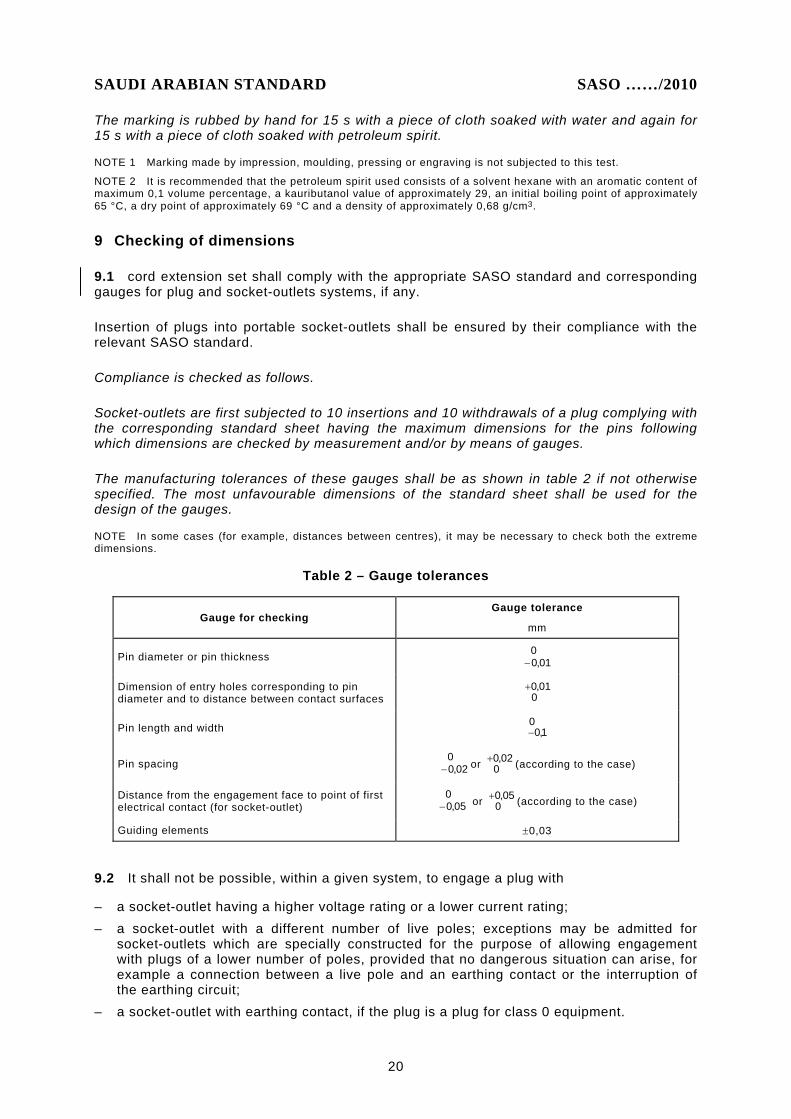
Table 2 – Gauge tolerances
Gauge for checking Gauge tolerance
mm
Pin diameter or pin thickness −0 010,
Dimension of entry holes corresponding to pin diameter and to distance between contact surfaces 0
0 01+ ,
Pin length and width 01,0−
Pin spacing −0 020, or 0
0 02+ , (according to the case)
Distance from the engagement face to point of first electrical contact (for socket-outlet) −0 05
0, or 0
0 05+ , (according to the case)
Guiding elements ±0,03
9.2 It shall not be possible, within a given system, to engage a plug with
– a socket-outlet having a higher voltage rating or a lower current rating; – a socket-outlet with a different number of live poles; exceptions may be admitted for
socket-outlets which are specially constructed for the purpose of allowing engagement with plugs of a lower number of poles, provided that no dangerous situation can arise, for example a connection between a live pole and an earthing contact or the interruption of the earthing circuit;
– a socket-outlet with earthing contact, if the plug is a plug for class 0 equipment.

SAUDI ARABIAN STANDARD SASO ……/2010
21
Compliance is checked by inspection or by manual test using gauges, the manufacturing tolerances of which shall be as specified in table 2.
In case of doubt, the impossibility of insertion is checked by applying the appropriate gauge for 1 min with a force of 150 N.
Where the use of elastomeric or thermoplastic material is likely to influence the result of the test, it is carried out at an ambient temperature of (35 ± 2) °C, both the accessories and the gauges being at this temperature.
NOTE For accessories of rigid material, such as thermosetting resins, ceramic material and the like, conformity to the relevant SASO standard ensures compliance with the requirement.
10 Protection against electric shock
NOTE For the purposes of this clause, lacquer, enamel and sprayed insulating coatings are not considered as insulating material.
10.1 Cord extension sets shall be so designed and constructed that when they are used as for normal use, live parts are not accessible, even after removal of parts which can be removed without the use of a tool.
Live parts of plugs shall not be accessible when the plug is in partial or complete engagement with a portable socket-outlet.
Compliance is checked by inspection and, if necessary, by the following test.
The standard test finger, test probe B of IEC 61032, is applied in every possible position, an electrical indicator with a voltage between 40 V and 50 V being used to show contact with the relevant parts.
For plugs, the test finger is applied when the plug is in partial and complete engagement with a socket-outlet.
For accessories where the use of thermoplastic or elastomeric material is likely to influence the requirements, one additional test is made but at an ambient temperature of (35 ± 2)°C, the accessories being at this temperature.
During this additional test the accessories are subjected for 1 min to a force of 75 N, applied through the tip of a straight unjointed test finger, test probe 11 of IEC 61032. This finger with an electrical indicator as described above is applied to all places where yielding of insulating material could impair the safety of the accessory, but is not applied to membranes or the like and is applied to thin-walled knock-outs but with a force of 10 N.
During this test, accessories, with their associated mounting means, shall not deform to such an extent that those dimensions shown in the relevant standard sheets which ensure safety are unduly altered and no live parts shall be accessible.
Each specimen of plug or portable socket-outlet is then pressed between two flat surfaces with a force of 150 N for 5 min, as shown in figure 8. The specimen is checked 15 min after removal from the test apparatus, and shall not show such deformation as it would result in undue alteration of those dimensions shown in the relevant standard sheets which ensure safety.
10.2 Parts which are accessible when the accessories are assembled, with the exception of small screws and the like, isolated from live parts, for fixing bases and covers or cover-plates of portable socket-outlets, shall be made of insulating material; however, the covers or cover-

SAUDI ARABIAN STANDARD SASO ……/2010
22
plates and accessible parts of plugs and portable socket-outlets may be made of metal if the requirements given in 10.2.1 or 10.2.2 are fulfilled.

SAUDI ARABIAN STANDARD SASO ……/2010
23
10.2.1 Metal covers or cover-plates are protected by supplementary insulation made by insulating linings or insulating barriers fixed to covers or cover-plates or to the body of accessories, in such a way that the insulating linings or insulating barriers cannot be removed without being permanently damaged, or so designed that they cannot be replaced in an incorrect position and that, if they are omitted, the accessories are rendered inoperable or manifestly incomplete and there is no risk of accidental contact between live parts and metal covers or cover-plates, for example through their fixing screws, even if a conductor should come away from its terminal, and if precautions are taken in order to prevent creepage distances or clearances becoming less than the values specified in table 23.
In the case of single-pole insertion, the requirement given in 10.3 applies.
Compliance is checked by inspection.
The above linings or barriers shall comply with the tests of clauses 17 and 27.
10.2.2 Metal covers or cover-plates are automatically connected, through a low resistance connection, to the earth during fixing of the cover or the cover-plate itself.
The creepage distances and the clearances between the live pins of a plug when fully inserted and the earthed metal cover of a socket-outlet shall comply with items 2 and 7 of table 23, respectively; in addition, in the case of single-pole insertion, the requirement given in 10.3 applies.
NOTE 1 Fixing screws or other means are allowed.
Compliance is checked by inspection and by the tests of 11.5.
10.3 It shall not be possible to make contact between a pin of a plug and a live socket-contact of a socket-outlet while any other pin is accessible.
Compliance is checked by manual test and by means of gauges based on the most unfavourable dimensions of the relevant SASO standard; the tolerances of the gauges shall be as specified in table 2.
For accessories with enclosures or bodies of thermoplastic material, the test is made at an ambient temperature of (35 ± 2) °C, both the accessory and the gauge being at this temperature.
For socket-outlets with enclosures or bodies of rubber or polyvinyl chloride, the gauge is applied with a force of 75 N for 1 min.
NOTE 1 Single-pole insertion may be prevented by the use of a sufficiently large cover or cover-plate. NOTE 2 the use of a shutter as the only means to prevent single-pole insertion is not allowed.
10.4 External parts of plugs, with the exception of assembly screws and the like, current-carrying and earthing pins, earthing straps and accessible metal parts fulfilling the requirements of 10.2, shall be of insulating material.
Compliance is checked by inspection.
10.5 Shuttered socket-outlets shall, in addition, be so constructed that live parts are not accessible without a plug in engagement, with the gauges shown in figures 9 and 10.
The gauges shall be applied to the entry holes corresponding to the live contacts only and shall not touch live parts.

SAUDI ARABIAN STANDARD SASO ……/2010
24
To ensure this degree of protection, portable socket-outlets shall be so constructed that live contacts are automatically screened when the plug is withdrawn.
The means for achieving this shall be such that they cannot easily be operated by anything other than a plug and shall not depend upon parts which are liable to be lost.
An electrical indicator with a voltage between 40 V and 50 V included is used to show contact with the relevant part.
Compliance is checked by inspection and for portable socket-outlets with a plug completely withdrawn by applying the above gauges as follows.
The gauge according to figure 9 is applied to the entry holes corresponding to the live contacts with a force of 20 N.
The gauge is applied to the shutters in the most unfavourable position, successively in three directions, to the same place for approximately 5 s in each of the three directions.
During each application the gauge shall not be rotated and it shall be applied in such a way that the 20 N force is maintained. When moving the gauge from one direction to the next, no force is applied but the gauge shall not be withdrawn.
A steel gauge, according to figure 10, is then applied with a force of 1 N and in three directions, for approximately 5 s in each direction, with independent movements, withdrawing the gauge after each movement.
For portable socket-outlets with enclosures or bodies of thermoplastic material, the test is made at an ambient temperature of (35 ± 2)°C, both the socket-outlets and the gauge being at this temperature.
10.6 Earthing contacts of a socket-outlet shall be so designed that they cannot be deformed by the insertion of a plug, to such an extent that safety is impaired.
Compliance is checked by the following test.
The portable socket-outlet is placed in such a position that the socket-contacts are in a vertical position.
A test plug, corresponding to the type of socket-outlet, is inserted into the socket-outlet with a force of 150 N which is applied for 1 min.
After this test, the portable socket-outlet shall still comply with the requirements of clause 9.
10.7 Cord extension sets shall be so constructed that, after assembled, live parts shall not be accessible.
Compliance is checked by inspection and by applying with a test wire of 1,0 mm diameter (see figure 10) a force of 1 N on all accessible surfaces in the most unfavourable conditions without a plug inserted, and where the cable enters the plug and the portable socket-outlet in every possible position.
For portable socket-outlets with enclosures or bodies of thermoplastic material, the test is made at an ambient temperature of (35 ± 2) °C, both the socket-outlets and the gauge being at this temperature.
During this test, it shall not be possible to touch live parts with the gauge.

SAUDI ARABIAN STANDARD SASO ……/2010
25
An electrical indicator as described in 10.1 shall be used.
10.8 Supplementary protection
Cord extension sets having four socket-outlets and above shall be provided with supplementary overcurrent protection having the same rating of the cord extension set.
The overcurrent protective device shall be automatic trip free, manual-reset type and shall be connected between the power supply cord and the socket-outlets.
Overcurrent protective device incorporated with cord extension set is not intended to be a substitute for branch circuit protection.
The supplementary protective device shall not open during the temperature rise test.
Compliance is checked by inspection and testing as per the relevant SASO Standard 1612.
Three previously untested cord extension sets are to be subjected to “overcurrent test” each one shall be tested once.
11 Provision for earthing
11.1 Earthing contacts of the accessories shall be so constructed that when inserting the plug the earth connection is made before the current-carrying contacts of the plug become live.
When withdrawing the plug, the current-carrying pins shall separate before the earth connection is broken.
Compliance is checked by inspection of the manufacturing drawings, taking into account the effect of tolerances, and by checking the specimens against these drawings.
NOTE Conformity with the relevant SASO standard ensures compliance with this requirement.
11.2 Earthing terminals of rewirable accessories shall comply with the appropriate requirements of clause 12.
They shall be of the same size as the corresponding terminals for the supply conductors.
Earthing terminals of rewirable accessories with earthing contact shall be internal.
Earthing terminals of portable socket-outlets shall be fixed to the base or to a part reliable fixed to the base.
Earthing terminals connection shall be ensured under all conditions which may occur in normal use, including loosening of cover-fixing screws, careless mounting of the cover, etc.
Except as mentioned above, parts of the earthing circuit shall be in one piece or shall be reliably connected together by riveting, welding, or the like.
NOTE 1 The requirement regarding the connection between an earthing contact fixed to a cover and an earthing terminal may be met by the use of a solid pin and a resilient socket-contact.
NOTE 2 For the purpose of the requirements of this subclause, screws are not considered as parts of contact pieces.

SAUDI ARABIAN STANDARD SASO ……/2010
26
NOTE 3 When considering the reliability of the connection between parts of the earthing circuit, the effect of possible corrosion is taken into account.
11.3 Accessible metal parts of portable socket-outlets, which may become live in the event of an insulation fault, shall be permanently and reliably connected to the earthing terminal.
NOTE 1 This requirement does not apply to the metal cover-plates mentioned in 10.2.1.
NOTE 2 For the purpose of this requirement, small screws and the like, electrically separated from live parts, for fixing bases, covers, or cover-plates, are not considered as accessible parts which may become live in the event of an insulation fault.
11.4 Compliance with 11.2 and 11.3 is checked by inspection and by the tests of clause 12.
11.5 The connection between the earthing terminal and accessible metal parts to be connected thereto, shall be of low resistance.
Compliance is checked by the following test.
A current derived from an a.c. source having a no-load voltage not exceeding 12 V and equal to 1,5 times the rated current or 25 A, whichever is the greater, is passed between the earthing terminal and each of the accessible metal parts in turn.
The voltage drop between the earthing terminal and the accessible metal part is measured, and the resistance calculated from the current and this voltage drop.
In no case shall the resistance exceed 0,05 Ω.
NOTE Care should be taken that the contact resistance between the tip of the measuring probe and the metal part under test does not influence the test results.
12 Terminals and terminations
12.1 General
All the tests on terminals, with the exception of the test of 12.3.11 and 12.3.12 shall be made after the tests of clause 16.
12.1.1 Rewirable portable socket-outlets shall be provided with screw-type terminals, screwless terminals or terminals with screw clamping.
Rewirable plugs shall be provided with terminals with screw clamping or screw-type terminals.
If pre-soldered flexible conductors are used, care shall be taken that in screw-type terminals the pre-soldered area shall be outside the clamp area when connected as for normal use.
The means for clamping the conductors in the terminals shall not serve to fix any other component, although they may hold the terminals in place or prevent them from turning.
NOTE Copper conductors with the strands pre-welded together are allowed. 12.1.2 Non-rewirable accessories shall be provided with soldered, welded, crimped or equally effective permanent connections (termination); screwed or unlocked snap-on connections shall not be used. NOTE - Snap-on connections are allowed provided the assembly is mechanically locked. Connections made by crimping a pre-soldered flexible conductor are not permitted, unless the soldered area is outside the crimping area.
12.1.3 Compliance is checked by inspection and by the tests of 12.2 or 12.3, as applicable.

SAUDI ARABIAN STANDARD SASO ……/2010
27
12.2 Terminals with screw clamping for copper conductors
12.2.1 Accessories shall be provided with terminals which shall allow the proper connection of copper conductors having nominal cross-sectional area of each conductor of the cord extensions sets not less than 1.5 mm2
The conductor space shall be at least that specified in figures 2, 3, 4 or 5.
Compliance is checked by inspection, by measurement and by fitting conductors of the smallest and largest nominal cross-sectional areas specified.
12.2.2 Terminals with screw clamping shall allow the conductor to be connected without special preparation.
Compliance is checked by inspection.
NOTE The term "special preparation" covers soldering of the wires of the conductor, use of cable lugs, formation of eyelets, etc., but not the reshaping of the conductor before its introduction into the terminal or the twisting of a flexible conductor to consolidate the end.
12.2.3 Terminals with screw clamping shall have adequate mechanical strength.
Screws and nuts for clamping the conductors shall have a metric ISO thread or a thread comparable in pitch and mechanical strength.
Screws shall not be of metal which is soft or liable to creep, such as zinc or aluminium.
Compliance is checked by inspection and by the tests of 12.2.6 and 12.2.8.
12.2.4 Terminals with screw clamping shall be resistant to corrosion.
Terminals, the body of which is made of copper or copper alloy as specified in 26.5, are considered as complying with this requirement.
Compliance is checked by inspection or by chemical analysis if necessary.
12.2.5 Terminals with screw clamping shall be so designed and constructed that they clamp the conductor(s) without undue damage to the conductor(s).
Compliance is checked by the following test.
The terminal is placed in the test apparatus according to figure 11 and fitted with flexible conductor(s), with the smallest and then with the largest nominal cross-sectional area, the clamping screw(s) or nut(s) being tightened with the torque according to table 6.
The length of the test conductor shall be 75 mm longer than the height (H) specified in table 9.
The end of the conductor is passed through an appropriate sized bushing in a platen positioned at a height (H) below the equipment, as given in table 9. The bushing is positioned in a horizontal plane such that its centre line describes a circle of 75 mm diameter, concentric with the centre of the clamping unit in the horizontal plane; the platen is then rotated at a rate of (10 ± 2) r/min.
The distance between the mouth of the clamping unit and the upper surface of the bushing shall be within 15 mm of the height specified in table 9. The bushing may be lubricated to prevent binding, twisting, or rotation of the insulated conductor.
A mass as specified in table 9 is to be suspended from the end of the conductor. The duration of the test shall be 15 min.

SAUDI ARABIAN STANDARD SASO ……/2010
28
During the test, the flexible conductor shall neither slip out of the clamping unit nor break near the clamping unit, nor shall the conductor be damaged in such a way as to render it unfit for further use.
12.2.6 Terminals with screw clamping shall be so designed that they clamp the conductor reliably between metal surfaces.
Compliance is checked by inspection and by the following test.
The terminals are fitted with flexible conductors for plugs and portable socket-outlets using conductors of the smallest and largest nominal cross-sectional area, the terminal screws being tightened with a torque equal to two-thirds of the torque shown in the appropriate column of table 6.
Each conductor is then subjected to a pull as specified in table 4, applied without jerks, for 1 min, in the direction of the axis of the conductor space.
Table 4 – Values for pull test for screw-type terminals
Nominal cross-sectional areaof conductors
accepted by the terminal mm2
Pull N
1,5 40
Above 1,5 up to 4 inclusive 50
If the clamp is provided for two or three conductors, the appropriate pull is applied consecutively to each conductor.
During the test, the conductor shall not move noticeably in the terminal.
If the clamp is intended for connection of more than two conductors, reference is made for the testing to the requirements given in the appropriate Part of IEC 60998.
12.2.7 Terminals with screw clamping shall be so designed or placed that the flexible conductor can’t slip out while the clamping screws or nuts are tightened.
Compliance is checked by the following test.
The terminals of plugs and portable socket-outlets are checked with flexible conductors having the largest nominal cross-sectional area.
Terminals intended for the looping-in of two or three conductors are checked, being fitted with the permissible number of conductors.
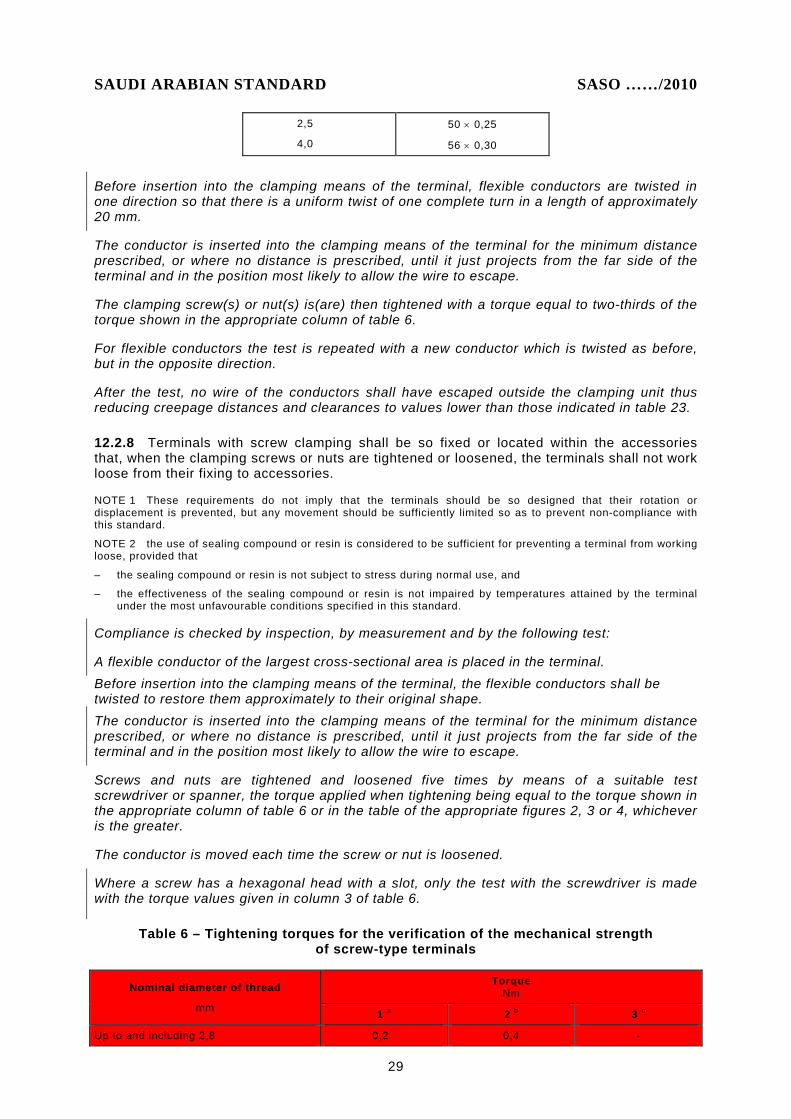
The terminals are fitted with conductors having the composition shown in table 5.
Table 5 – Composition of conductors
Nominal cross-sectionalarea
Number of wires (n) and nominal diameter of
conductors n × mm
mm2 Flexible conductor
1,5 30 × 0,25
SAUDI ARABIAN STANDARD SASO ……/2010
29
2,5
4,0
50 × 0,25
56 × 0,30
Before insertion into the clamping means of the terminal, flexible conductors are twisted in one direction so that there is a uniform twist of one complete turn in a length of approximately 20 mm.
The conductor is inserted into the clamping means of the terminal for the minimum distance prescribed, or where no distance is prescribed, until it just projects from the far side of the terminal and in the position most likely to allow the wire to escape.
The clamping screw(s) or nut(s) is(are) then tightened with a torque equal to two-thirds of the torque shown in the appropriate column of table 6.
For flexible conductors the test is repeated with a new conductor which is twisted as before, but in the opposite direction.
After the test, no wire of the conductors shall have escaped outside the clamping unit thus reducing creepage distances and clearances to values lower than those indicated in table 23.
12.2.8 Terminals with screw clamping shall be so fixed or located within the accessories that, when the clamping screws or nuts are tightened or loosened, the terminals shall not work loose from their fixing to accessories.
NOTE 1 These requirements do not imply that the terminals should be so designed that their rotation or displacement is prevented, but any movement should be sufficiently limited so as to prevent non-compliance with this standard.
NOTE 2 the use of sealing compound or resin is considered to be sufficient for preventing a terminal from working loose, provided that
– the sealing compound or resin is not subject to stress during normal use, and
– the effectiveness of the sealing compound or resin is not impaired by temperatures attained by the terminal under the most unfavourable conditions specified in this standard.
Compliance is checked by inspection, by measurement and by the following test:
A flexible conductor of the largest cross-sectional area is placed in the terminal. Before insertion into the clamping means of the terminal, the flexible conductors shall be twisted to restore them approximately to their original shape. The conductor is inserted into the clamping means of the terminal for the minimum distance prescribed, or where no distance is prescribed, until it just projects from the far side of the terminal and in the position most likely to allow the wire to escape.
Screws and nuts are tightened and loosened five times by means of a suitable test screwdriver or spanner, the torque applied when tightening being equal to the torque shown in the appropriate column of table 6 or in the table of the appropriate figures 2, 3 or 4, whichever is the greater.
The conductor is moved each time the screw or nut is loosened.
Where a screw has a hexagonal head with a slot, only the test with the screwdriver is made with the torque values given in column 3 of table 6.
Table 6 – Tightening torques for the verification of the mechanical strength of screw-type terminals
Nominal diameter of thread
mm
Torque Nm
1 a 2 b 3 c
Up to and including 2,8 0,2 0,4 -

SAUDI ARABIAN STANDARD SASO ……/2010
30
Over 2,8 up to and including 3,0
Over 3,0 up to and including 3,2
Over 3,2 up to and including 3,6
Over 3,6 up to and including 4,1
Over 4,1 up to and including 4,7
Over 4,7 up to and including 5,3
0,25
0,3
0,4
0,7
0,8
0,8
0,5
0,6
0,8
1,2
1,8
2,0
–
–
–
1,2
1,2
1,4 a Column 1 applies to screws without a head if the screw, when tightened, does not protrude from the hole and to other screws which cannot be tightened by means of a screwdriver with a blade wider than the diameter of the screw. b Column 2 applies to other screws which are tightened by means of a screwdriver and to screws and nuts which are tightened by means other than a screwdriver. c Column 3 applies to nuts of mantle terminals which are tightened by means of a screwdriver.
Where a screw has a hexagonal head with a slot and the values in columns III and IV are different, the test is made twice, first on a set of 3 samples applying to the hexagonal head the torque specified in column IV and then on another set of three samples, applying the torque specified in column III by means of a screwdriver. If the values in columns III and IV are the same, only the test with the screwdriver is made. During the test, terminals shall not work loose and there shall be no damage, such as breakage of screws or damage to heads, slots (rendering the use of the appropriate screwdriver impossible), threads, washers or stirrups that will impair the further use of the terminal.
NOTE 1 For mantle terminals the specified nominal diameter is that of the slotted stud.
NOTE 2 The shape of the blade of the test screwdriver should suit the head of the screw to be tested.
NOTE 3 The screws and nuts should not be tightened in jerks.
12.2.9 Clamping screws or nuts of earthing terminals with screw clamping shall be adequately locked against accidental loosening and it shall not be possible to loosen them without the aid of a tool.
Compliance is checked by manual test.
NOTE In general, the designs of terminals shown in figures 2, 3, 4 and 5 provide sufficient resiliency to comply with this requirement; for other designs, special provisions, such as the use of an adequately resilient part which is not likely to be removed inadvertently, may be necessary.
12.2.10 Earthing terminals with screw clamping shall be such that there is no risk of corrosion resulting from contact between these parts and the copper of the earthing conductor, or any other metal that is in contact with these parts.
The body of the earthing terminal shall be of brass or other metal no less resistant to corrosion, unless it is a part of the metal frame or enclosure, when the screw or nut shall be of brass or other metal no less resistant to corrosion.
If the body of the earthing terminal is a part of a frame or enclosure of aluminium alloy, precautions shall be taken to avoid the risk of corrosion resulting from contact between copper and aluminium or its alloys.
Compliance is checked by inspection.
NOTE Screws or nuts of plated steel withstanding the corrosion test are considered to be of a metal no less resistant to corrosion than brass.
12.2.11 For pillar terminals, the distance between the clamping screw and the end of the conductor, when fully inserted, shall be at least that specified in figure 2.

SAUDI ARABIAN STANDARD SASO ……/2010
31
NOTE The minimum distance between the clamping screw and the end of the conductor applies only to pillar terminals in which the conductor cannot pass right through.
For mantle terminals, the distance between the fixed part and the end of the conductor, when fully inserted, shall be at least that specified in figure 5.
Compliance is checked by measurement, after a solid conductor of the largest nominal cross-sectional area, has been fully inserted and fully clamped.
12.3 Screwless terminals for copper conductors
12.3.1 Screwless terminals may be of the type suitable for flexible copper conductors.
but the tests are carried out with rigid conductors first and then repeated with flexible conductors.
NOTE Subclause 12.3.1 is not applicable to socket-outlets provided with
– screwless terminals requiring the fixing of special devices to the conductors before clamping them in the screwless terminal, for example flat push-on connectors;
– screwless terminals requiring twisting of the conductors, for example, those with twisted joints;
– screwless terminals providing direct contact to the conductors by means of edges or points penetrating the insulation.
12.3.2 Screwless terminals shall be provided with two clamping units each allowing the proper connection of flexible copper conductors having nominal cross-sectional areas as shown in table 7.
Table 7 – Relationship between rated current and connectable cross-sectional areas of copper conductors for screwless terminals
Rated current
A
Conductors
Nominal cross-sectionalareas mm2
Diameter of largest rigid conductor
mm
Diameter of largest flexible conductor
mm
13 A and 15A From 1,5 up to 2,5 inclusive 2,13 2,21
SAUDI ARABIAN STANDARD SASO ……/2010
32
When two conductors have to be connected, each conductor shall be introduced in a separate independent clamping unit (not necessarily in separate holes).
Compliance is checked by inspection and by fitting conductors of the smallest and largest nominal cross-sectional areas specified.
12.3.3 Screwless terminals shall allow the conductor to be connected without special preparation.
Compliance is checked by inspection.
NOTE The term "special preparation" covers soldering of the wires of the conductor, use of terminal ends, etc., but not the reshaping of the conductor before introduction into the terminal or the twisting of a flexible conductor to consolidate the end.
12.3.4 Parts of screwless terminals mainly intended to carry current shall be of materials as specified in 26.5.
Compliance is checked by inspection and by chemical analysis.
NOTE Springs, resilient units, clamping plates and the like are not considered as parts mainly intended to carry current.
12.3.5 Screwless terminals shall be so designed that they clamp the specified conductors with sufficient contact pressure and without undue damage to the conductor.
The conductor shall be clamped between metal surfaces.
NOTE Conductors are considered to be unduly damaged if they show appreciably deep or sharp indentations.
Compliance is checked by inspection and by the tests of 12.3.10.
12.3.6 It shall be clear how the connection and disconnection of the conductors is to be made.
The intended disconnection of a conductor shall require an operation, other than a pull on the conductor, so that it can be made manually with or without the help of a general purpose tool.
It shall not be possible to confuse the opening intended for the use of a tool to assist the connection or disconnection with the opening intended for the conductor.
Compliance is checked by inspection and by the tests of 12.3.10.
12.3.7 Screwless terminals which are intended to be used for the interconnection of two or more conductors shall be so designed that
– during the insertion, the operation of the clamping means of one of the conductors is independent of the operation of that of the other conductor(s);
– during the disconnection, the conductors can be disconnected either at the same time or separately;
– each conductor shall be introduced in a separate clamping unit (not necessarily in separate holes);
– it shall be possible to clamp securely any number of conductors up to the maximum as designed.

SAUDI ARABIAN STANDARD SASO ……/2010
33
Compliance is checked by inspection and by manual tests with the appropriate conductors (in number and size).
12.3.8 Screwless terminals of portable socket-outlets shall be designed so that adequate insertion of the conductor is obvious and over-insertion is prevented if further insertion is liable to reduce the creepage distances and/or clearances required in table 23, or to influence the operation of the portable socket-outlet.
NOTE For the purpose of this requirement, an appropriate marking indicating the length of insulation to be removed before the insertion of the conductor into the screwless terminal may be put on the socket-outlet or given in an instruction sheet which accompanies the socket-outlet.
Compliance is checked by inspection and by the tests of 12.3.10.
12.3.9 Screwless terminals shall be properly fixed to the portable socket-outlet.
They shall not work loose when the conductors are connected or disconnected during installation.
Compliance is checked by inspection and by the tests of 12.3.10.
Covering with sealing compound without other means of locking is not sufficient. Self-hardening resins may, however, be used to fix terminals which are not subject to mechanical stress in normal use.
12.3.10 Screwless terminals shall withstand the mechanical stresses occurring in normal use.
Compliance is checked by the following tests which are carried out with uninsulated conductors on one screwless terminal of each specimen, using a new specimen for each test.
The test is carried out with solid rigid copper conductors, first with conductors having the largest nominal cross-sectional area, and then with conductors having the smallest nominal cross-sectional area specified in table 7.
Conductors are connected and disconnected five times, new conductors being used each time, except for the fifth time, when the conductors used for the fourth connection are clamped at the same place. For each connection, the conductors are either pushed as far as possible into the terminal or are inserted so that adequate connection is obvious.
After each connection, the conductor is subjected to a pull of the value shown in table 8; the pull is applied without jerks, for 1 min, in the direction of the longitudinal axis of the conductor space.
Table 8 – Value for pull test for screwless-type terminals
Rated current A
Pull N
13 A and 15 A 30
During the application of the pull, the conductor shall not come out of the screwless terminal.
The test is then repeated with flexible conductors, making five connections and disconnections.
For Portable socket-outlets with screwless terminals, each conductor is subjected for 15 min to a circular motion with (10 ± 2) r/min using an apparatus, an example of which is shown in figure 11. During this test, a mass as specified in table 9 is suspended from the end of the conductor.

SAUDI ARABIAN STANDARD SASO ……/2010
34
Table 9 – Values for flexing under mechanical load test for copper conductors
Nominal cross-sectional area of conductora
mm2
Diameter of bushing holeb
mm
Height H
mm
Mass for conductor
kg
1,5 6,5 260 0,4
2,5 9,5 280 0,7
4,0 9,5 280 0,9
a Approximate relationship between mm2 and AWG sizes can be found in IEC 60999-1.
b If the bushing-hole diameter is not large enough to accommodate the conductor without binding, a bushing having the next larger hole size may be used.
During the test, the conductors shall not move noticeably in the clamping unit.
After these tests, neither the terminals nor the clamping means shall have worked loose and the conductors shall show no deterioration impairing their further use.
12.3.11 Screwless terminals shall withstand the electrical and thermal stresses occurring in normal use.
Compliance is checked by the following tests a) and b), which are carried out on five screwless terminals of portable socket-outlets which have not been used for any other test.
Both tests are carried out with new copper conductors.
a) The test is carried out loading the screwless terminals for 1 h with an alternating current as specified in table 10 and connecting rigid solid conductors 1 m long having the nominal cross-sectional area as specified in the same table.
The test is carried out on each clamping unit.
Table 10 – Test current for the verification of electrical and thermal stresses in normal use for screwless terminals
Rated current
A
Test current
A
Nominal cross-sectional area of the conductor
mm2
13 A and 15 A 22 2,5
During the test the current is not passed through the portable socket-outlet, but only through the terminals.
Immediately after this period, the voltage drop across each screwless terminal is measured with rated current flowing.
In no case shall the voltage drop exceed 15 mV.
The measurements are made across each screwless terminal and as near as possible to the place of contact.
If the back connection of the terminal is not accessible, the specimens may be adequately prepared by the manufacturer; care shall be taken not to affect the behaviour of the terminals.

SAUDI ARABIAN STANDARD SASO ……/2010
35
Care shall be taken to ensure that, during the period of the test, including the measurements, the conductors and the measurement devices are not moved noticeably.
b) The screwless terminals already subjected to the determination of the voltage drop specified in the previous test a) are tested as follows. During the test, a current equal to the test current value given in table 10 is passed.
The whole test arrangement, including the conductors, shall not be moved until the measurements of the voltage drop have been completed.
The terminals are subjected to 192 temperature cycles, each cycle having a duration of approximately 1 h and carried out as follows:
– the current flows for approximately 30 min; – for a further period of approximately 30 min no current flows.
The voltage drop in each screwless terminal is determined as prescribed for the test of a) after every 24 temperature cycles and after the 192 temperature cycles have been completed.
In no case shall the voltage drop exceed 22,5 mV or twice the value measured after the 24th cycle, whichever is the smaller.
After this test an inspection by normal or corrected vision without additional magnification shall show no changes evidently impairing further use such as cracks, deformations or the like.
In addition, the mechanical strength test according to 12.3.10 is repeated and all specimens shall withstand this test.
13 VOID
14 Construction of cord extension sets
14.1 Socket outlets to be used in cord extension sets shall have shutters.
Plugs and socket outlets shall comply with GSO IEC 60884-1.
Fused plugs shall comply with SASO 2203 and IEC 60884-2-1.
Flexible cable shall comply with the relevant SASO standards and IEC 60227 or IEC 60245.
The flexible cable shall have the same number of conductors as the poles in the socket-outlet(s). Earthing contacts are considered as one pole.
The earthing contact in the socket-outlet(s) shall be connected to the corresponding earthing contact of the plug.
Compliance is checked by inspection
14.2 the type, length of the flexible cable and nominal cross sectional area of the conductors of cord extension sets shall comply with table (11).

SAUDI ARABIAN STANDARD SASO ……/2010
36
Table 11 – type, length of the flexible cable and nominal cross sectional area of the conductors of cord extension sets
Rated current Lightest type of flexible cable Minimum nominal cross
sectional area of the conductors
Maximum length of the flexible cable
13 A / 220 V
60227 IEC 53 or 60245 IEC 53
1.5 mm2 5 m
2.5 mm2 30 m
15 A / 127 V
60227 IEC 53 or 60245 IEC 53
1.5 mm2 2 m
2.5 mm2 30 m
NOTE Cord extension sets for outdoor use shall be provided with cable type 60245 IEC 53 or equivalent.
The length of the cable is measured between the operating faces of the plug and the socket-outlet. In the case of multiple socket-outlets the measurement is taken to the socket-outlet closest to the plug.
Compliance is checked by inspection and measurement.
14.3 Plugs of extension cord sets:
14.3.1 Pins of plugs shall be
– locked against rotation, – not removable without dismantling the plug, – adequately fixed in the body of the plug when the plug is wired and assembled as for
normal use.
It shall not be possible to arrange the earthing or neutral pins or contacts of plugs in an incorrect position.
Compliance is checked by inspection, by manual test and by the tests of 24.2 and 24.10.
14.3.2 The rated current of the plug shall not be lower than the rated current of the socket-outlet. In a cord extension set protected against overload (e.g. having a fused plug or a protective overcurrent device), the rated current of the plug shall not be lower than the rated current of the protective overcurrent device.
For a cord extension set with a multiple portable socket-outlet and not incorporating a protective overcurrent device the rated current of the plug shall be at least the arithmetic sum of the highest rated currents of all plugs which can be inserted into the cord extension set or the same as the rated current of the relevant socket outlet of the fixed wiring, the plug is intended to be connected to, whichever is the lower.
Compliance is checked by inspection. 14.3.3 The rated voltage of the plug and the socket-outlet shall be the same. The rated voltage of the cable shall not be less than the rated voltage of the plug and socket-outlet. Compliance is checked by inspection.

SAUDI ARABIAN STANDARD SASO ……/2010
37
14.4 Earthing contacts and neutral contacts of portable socket-outlets shall be locked against rotation and removable only with the aid of a tool, after dismantling the socket-outlet.
Compliance is checked by inspection, by manual test and, for single portable socket-outlets, by the test of 24.2.
14.5 Socket-contact assemblies shall have sufficient resilience to ensure adequate contact pressure on plug pins.
Parts of socket-contact assemblies, which will be in contact with the portion of the pin intended to make electrical contact when the plug is fully inserted in the socket-outlet,
– shall not be of insulating material except ceramic, or other material with no less suitable characteristics, and
– shall ensure metallic contacts at least on two opposing sides of each pin.
The contact pressure of the contact tube shall not depend on soldered connection only.
Compliance is checked by inspection and by the tests of 9, 21 and 22.
14.6 Pins and socket-contacts shall be resistant to corrosion and abrasion.
Compliance is checked by an appropriate test.
14.7 The enclosures of rewirable portable accessories shall completely enclose the terminals and the ends of flexible cable.
The construction shall be such that the conductors can be properly connected and that, when the accessory is wired and assembled as for normal use, there is no risk that
– pressing the cores together causes damage to the conductor insulation likely to result in a breakdown of the insulation;
– a core, the conductor of which is connected to a live terminal is not necessarily pressed against accessible metal parts;
– a core, the conductor of which is connected to an earthing terminal is not necessarily pressed against live parts.
The construction shall be such that the flexible cable shall be properly fitted and assembled such as there is no risk make the flexible cable loose from the accessory in normal use e.g. by means of a flexible cable anchorage.
Compliance is checked by inspection and by manual test.
14.8 Rewirable portable accessories shall be designed in such a way that terminal screws or nuts cannot become loose and fall out of position in such a way that they establish an electrical connection between live parts and the earthing terminal or metal parts connected to the earthing terminal.
Compliance is checked by inspection and by manual test.
14.9 Rewirable portable accessories with earthing contact shall be designed with ample space for slack in the earthing conductor so that, if the strain relief is rendered inoperative,

SAUDI ARABIAN STANDARD SASO ……/2010
38
the connection of the earthing conductor is subjected to strain after the connections of the current-carrying conductors and, in case of excessive stress, the earthing conductor will break after the current-carrying conductors.
Compliance is checked by the following test.
The current-carrying conductors of a flexible cable are connected to the accessory in such a way that they are led from the strain relief to the corresponding terminals along the shortest possible path. Following which, the core of the earthing conductor is led to its terminal and cut off at a distance 8 mm longer than necessary when using the shortest possible path for its correct connection. The earthing conductor is then connected to the terminal. It shall then be possible to house the loop, which is formed by the earthing conductor owing to its surplus length when the accessory is assembled correctly.
In non-rewirable non-moulded-on accessories with earthing contact, the length of the conductors between the terminations and the cord anchorage shall be adjusted in such a way that the current-carrying conductors will be stressed before the earthing conductor, if the flexible cable slips in its anchorage.
Compliance is checked by inspection.
14.10 Terminals of rewirable portable accessories and terminations of non-rewirable portable accessories shall be located or shielded in such a way that loose wires from a conductor in the accessory will not present a risk of electric shock.
For non-rewirable moulded-on portable accessories, means shall be provided to prevent loose wires of a conductor from reducing the minimum isolation distance requirements between such wires and all accessible external surfaces of the accessory, with the exception of the engagement face of a plug.
Compliance is checked by the following:
– for rewirable accessories, the test of 14.10.1; – for non-rewirable non-moulded-on accessories, the test of 14.10.2; – for non-rewirable moulded-on accessories, by verification and inspection according to 14.10.3.
14.10.1 A 6 mm length of insulation is removed from the end of a flexible conductor, having the minimum required nominal cross-sectional area. One wire of the flexible conductor is left free and the remaining wires are fully inserted into and clamped in the terminal as for normal use.
The free wire is bent, without tearing the insulation back, in every possible direction, but without making sharp bends around barriers.
NOTE The prohibition against making sharp bends around barriers does not imply that the free wire has to be kept straight during the test. Sharp bends are, moreover, made if it is considered likely that such bends may occur during the normal assembly of the plug or portable socket-outlet, for example when a cover is pushed on.
The free wire of a conductor connected to a live terminal shall not touch any accessible metal part or be able to emerge from the enclosure when the accessory has been assembled.
The free wire of a conductor connected to an earthing terminal shall not touch a live part.
If necessary, the test is repeated with the free wire in another position.
14.10.2 A length of insulation equivalent to the maximum designed stripping length declared by the manufacturer plus 2 mm is removed from the end of a flexible conductor having the cross-sectional area as fitted. One wire of the flexible conductor is left free in the worst

SAUDI ARABIAN STANDARD SASO ……/2010
39
position whilst the remaining wires are terminated in a manner as used in the construction of the accessory.
The free wire is bent, without tearing the insulation back, in every possible direction but without making sharp bends around barriers.
NOTE The prohibition against making sharp bends around barriers does not imply that the free wire has to be kept straight during the test. Sharp bends are, moreover, made if it is considered likely that such bends may occur during the normal assembly of the plug or portable socket-outlet, for example, when a cover is pushed on.
The free wire of a conductor connected to a live termination shall not touch any accessible metal part or reduce the creepage distance and clearance through any constructional gap below 1,5 mm to the external surface.
The free wire of a conductor connected to an earth termination shall not touch any live part.
14.10.3 Non-rewirable moulded-on accessories shall be inspected to verify that there are means to prevent stray wires of the conductor and/or live parts reducing the minimum distance through insulation to the external accessible surface below 1,5 mm (with the exception of the engagement face of plugs).
NOTE The verification of "means" may require the checking of the product construction or assembly method.
14.11 For rewirable portable accessories:
– it shall be clear how the relief from strain and the prevention of twisting is intended to be effected;
– the cord anchorage, or at least part of it, shall be integral with or fixed to one of the component parts of the plug or portable socket-outlet;
– makeshift methods, such as tying the flexible cable in a knot or tying the ends with string, shall not be used;
– the cord anchorage shall be suitable for the different types of flexible cable which may be connected to it;
– screws, if any, which have to be operated to clamp the flexible cable, shall not serve to fix any other component; NOTE This does not exclude a cover serving to retain the flexible cable in position in the cord anchorage provided the cable remains in place in the accessory when the cover is removed.
– cord anchorages shall be of insulating material or be provided with an insulating lining fixed to the metal parts;
– metal parts of cord anchorages, including clamping screws, shall be insulated from the earthing circuit.
Compliance is checked by inspection and, if applicable, by manual test.
14.12 For rewirable portable accessories and non-rewirable non-moulded on portable accessories it shall not be possible to remove covers or parts of them intended to ensure protection against electric shock without the use of a tool.
Compliance is checked as follows:
– for covers or parts of them whose fixing is of screw-type, compliance is checked by inspection;
– for covers or parts of them whose fixing is not dependent on screws and whose removal may give access to live parts, compliance is checked by the tests of 24.14.
SAUDI ARABIAN STANDARD SASO ……/2010
40
14.13 If covers of portable socket-outlets are provided with bushings for the entry holes for the pins, these bushes shall not be removable from the outside or detachable inadvertently from the inside, when the cover is removed.
14.14 Screws intended to allow access to the interior of the accessory shall be captive.
NOTE The use of tight-fitting washers of cardboard or the like is deemed to be an adequate method for making screws captive.
Compliance with the requirements of 14.13 and 14.14 is checked by inspection.
14.15 The engagement face of plugs shall have no projections other than the pins, when the plug is wired and assembled as for normal use.
Compliance is checked by inspection, after fitting conductors of the largest nominal cross-sectional are.
NOTE The earthing contacts are not considered as projections from the engagement face.
14.16 Portable socket-outlets shall be designed in such a way that full engagement of associated plugs is not prevented by any projection from their engagement face.
Compliance is checked by determining that the gap between the engagement face of the socket outlet and the plug does not exceed 1 mm when the plug is inserted into the socket outlet as far as it will go.
14.17 Portable accessories of IP code higher than IP20 shall be enclosed according to their IP classification when they are fitted with cables.
Plugs having an IP code higher than IP20, with the exception of the engagement face, shall be adequately enclosed when fitted with a flexible cable as for normal use.
Portable socket-outlets having an IP code higher than IP20 shall be adequately enclosed when fitted with a flexible cable as for normal use and without a plug in engagement.
Lid springs, if any, shall be made of corrosion-resistant material, such as bronze or stainless steel.
Compliance is checked by inspection and by the tests of 16.2.
NOTE Adequate enclosure when the plug is not in position may be achieved by means of a lid.
This requirement does not imply that the lid, if any, or the entry openings for the pins need be closed when the plug is not in position, provided that the accessory passes the relevant test for the verification of the ingress of water.
14.18 Portable socket-outlets having means for suspension from a wall or other mounting surfaces shall be so designed that the suspension means do not allow access to live parts.
There shall be no free openings between the space intended for the suspension means, by which the socket-outlet is fixed to the wall, or other mounting surface and live parts.
Compliance is checked by inspection and by the tests of 24.11, 24.12 and 24.13.
14.19 Combinations of portable accessories and switches, protective devices or other devices shall comply with the relevant individual SASO or IEC standards, if a relevant combined product standard does not exist.
Compliance is checked, by testing the components according to the relevant SASO or IEC standard.

SAUDI ARABIAN STANDARD SASO ……/2010
41
NOTE For combination with RCDs, see IEC 61540.
14.20 Portable accessories shall not be an integral part of lampholders.
Compliance is checked by inspection.
14.21 Cord extension sets with earthing can accept plugs of class II equipments.
14.22 Components, such as switches and fuses, incorporated in accessories shall comply with the relevant SASO or IEC standard as far as it reasonably applies.
Compliance is checked by inspection and, if necessary, by testing the component according to the relevant SASO or IEC standard.
14.23 VOID
14.24 Plugs shall be shaped in such a way and/or made of such material that they can easily be withdrawn by hand from the relevant socket-outlets.
In addition, the gripping surfaces shall be so designed that the plug can be withdrawn without having to pull the flexible cable.
Compliance is checked by inspection and in case of doubt by test.
NOTE Examples of possible tests are given in Annex C.
14.25 Membranes in inlet openings of portable accessories shall meet the requirements that membranes (grommets) in inlet openings shall be reliably fixed and shall not be displaced by the mechanical and thermal stresses occurring in normal use.
Compliance is checked by inspection and by the following test.
Membranes are tested when assembled in the accessory.
First the accessories are fitted with membranes which have been subjected to the treatment specified in 16.1.
The accessories are then placed for 2 h in a heating cabinet as described in 16.1, the temperature being maintained at (40 ± 2) °C.
Immediately after this period, a force of 30 N is applied for 5 s to various parts of the membranes by means of the tip of a straight unjointed test finger (test probe 11 of IEC 61032).
During these tests, the membranes shall not deform to such an extent that live parts become accessible.
For membranes likely to be subjected to an axial pull in normal use, an axial pull of 30 N is applied for 5 s.
During this test, the membranes shall not become detached.
The test is then repeated with membranes which have not been subjected to any treatment.
14.26 Cord extension sets may be provided with suitable switches and indicator lights singly or any combination.

SAUDI ARABIAN STANDARD SASO ……/2010
42
Switches for 220 V cord extension sets, if any, shall be double pole switch.
15 VOID
16 Resistance to ageing, protection provided by enclosures, and resistance to humidity
16.1 Resistance to ageing
Accessories shall be resistant to ageing.
Parts intended for decorative purposes only, such as certain lids, shall be removed if possible and these parts are not subjected to the test.
Compliance is checked by the following test.
Accessories are subjected to a test in a heating cabinet with an atmosphere having the composition and pressure of the ambient air and ventilated by natural circulation.
For portable socket-outlets, a test plug as specified in Clause 20 shall be inserted into the socket-outlet during the test.
The temperature in the cabinet is (70 ± 2) °C.
The specimens are kept in the cabinet for seven days (168 h).
The use of an electrically heated cabinet is recommended.
Natural circulation may be provided by holes in the wall of the cabinet.
After the treatment, the specimens are removed from the cabinet and kept at a room temperature and relative humidity between 45 % and 55 % for at least four days (96 h).
The specimens shall show no crack visible with normal or corrected vision without additional magnification, nor shall the material have become sticky or greasy, this being judged as follows:
– with the forefinger wrapped in a dry piece of rough cloth the specimen is pressed with a force of 5 N;
– no traces of the cloth shall remain on the specimen and the material of the specimen shall not stick to the cloth.
After the test, the specimens shall show no damage which would lead to non-compliance with this standard.
For portable socket-outlets, after having withdrawn the test plug from the socket-outlet the contact pressure of the contact assembly is checked as specified in subclause 22.2 with the single-pin gauge. The gauge shall not fall from the contact assembly within 30 s.
NOTE The force of 5 N can be obtained in the following way:
– the specimen is placed on one of the pans of a balance and the other pan is loaded with a mass equal to the mass of the specimen plus 500 g;
SAUDI ARABIAN STANDARD SASO ……/2010
43
– equilibrium is then restored by pressing the specimen with the forefinger, wrapped in a dry piece of rough cloth.
16.2 Protection degree of the cord extension set
The protection degree of the cord extension set is the same as the lowest protection degree of the plug and the portable socket outlet.
Compliance is checked by inspection.
16.3 Resistance to humidity
Accessories shall be proof against humidity which may occur in normal use.
Compliance is checked by the humidity treatment described in this subclause, followed immediately by the measurement of the insulation resistance and by the electric strength test specified in clause 17.
Parts which can be removed without the aid of a tool, are removed and subjected to the humidity treatment along with the main part; spring lids are open during this treatment.
The humidity treatment is carried out in a humidity cabinet containing air with a relative humidity maintained between 91 % and 95 %.
The temperature of the air in which the specimens are placed is maintained within ±1 K of any convenient value t between 20 °C and 30 °C.
Before being placed in the humidity cabinet, the specimens are brought to a temperature between t and (t + 4) °C.
The specimens are kept in the cabinet for
– two days (48 h) for accessories having an IP code of IPX0; – seven days (168 h) for accessories having an IP code higher than IPX0.
NOTE 1 In most cases, the specimens may be brought to the specified temperature by keeping them at this temperature for at least 4 h before the humidity treatment.
NOTE 2 A relative humidity between 91 % and 95 % can be obtained by placing in the humidity cabinet a saturated solution of sodium sulphate (Na2 SO4) or potassium nitrate (KNO3) in water, having a sufficiently large contact surface with the air.
NOTE 3 In order to achieve the specified conditions within the cabinet, it is necessary to ensure constant circulation of the air within and, in general, to use a cabinet which is thermally insulated.
After this treatment, the specimens shall show no damage within the meaning of this standard.
17 Insulation resistance and electric strength
The insulation resistance and electric strength of accessories shall be adequate.
Compliance is checked by the following tests, which are made immediately after the test of 16.3, in the humidity cabinet or in the room in which the specimens were brought to the prescribed temperature, after re-assembly of those parts which can be removed without the aid of a tool, which were removed for the test.
17.1 The insulation resistance is measured with a d.c. voltage of approximately 500 V, the measurement being made 1 min after application of the voltage.
SAUDI ARABIAN STANDARD SASO ……/2010
44
The insulation resistance shall be not less than 5 MΩ.

SAUDI ARABIAN STANDARD SASO ……/2010
45
17.1.1 For socket-outlets, the insulation resistance is measured consecutively:
a) between all poles connected together and the body, the measurement being made with a plug in engagement;
b) between each pole in turn and all others, these being connected to the body with a plug in engagement;
c) between any metal enclosure and metal foil in contact with the inner surface of its insulating linings, if any;
NOTE 1 This test is only made if an insulating lining is necessary to provide insulation.
d) between any metal part of the cord anchorage, including clamping screws, and earthing terminal(s) or earthing contact(s), if any, of portable socket-outlets;
e) between any metal part of the cord anchorage of portable socket-outlets and a metal rod of the maximum diameter of the flexible cable inserted in its place (see table 17).
The term "body" used in a) and b) includes all accessible metal parts, fixing screws of bases or covers, external assembly screws, earthing terminals or earthing contacts.
NOTE 2 Measurements c), d) and e) are not made on non-rewirable portable socket-outlets.
NOTE 3 While wrapping the metal foil round the outer surface or placing it in contact with the inner surface of parts of insulating material, it is pressed against holes or grooves, without any appreciable force, by means of a straight unjointed test finger test probe 11 of IEC 61032.
17.1.2 For plugs, the insulation resistance is measured consecutively
a) between all poles connected together and the body; b) between each pole in turn and all others, these being connected to the body; c) between any metal part of the cord anchorage, including clamping screws, and earthing
terminal(s) or earthing contact(s), if any; d) between any metal part of the cord anchorage and a metal rod of the maximum diameter
of the flexible cable inserted in its place (see table 17).
The term "body" used in a) and b) includes accessible metal parts, external assembly screws, earthing terminals, earthing contacts and a metal foil in contact with the outer surface of accessible external parts of insulating material, other than the engagement face.
NOTE 1 Measurements c) and d) are not made on non-rewirable plugs.
NOTE 2 While wrapping the metal foil round the outer surface or placing it in contact with the inner surface of parts of insulating material, it is pressed against holes or grooves, without any appreciable force, by means of a straight unjointed test finger test probe 11 of IEC 61032.
17.2 A voltage of substantially sine-wave form, having a frequency of 60 Hz, is applied for 1 min between the parts indicated in 17.1.
The test voltage shall be as follows:
– 1 250 V for accessories having a rated voltage of 127 V; – 2 000 V for accessories having a rated voltage of 220 V.
Initially, not more than half the prescribed voltage is applied, then it is raised rapidly to the full value.
SAUDI ARABIAN STANDARD SASO ……/2010
46
No flashover or breakdown shall occur during the test.
NOTE 1 The high-voltage transformer used for the test should be so designed that, when the output terminals are short-circuited after the output voltage has been adjusted to the appropriate test voltage, the output current is at least 200 mA.
NOTE 2 The overcurrent relay should not trip when the output current is less than 100 mA.
NOTE 3 Care is taken that the r.m.s. value of the test voltage applied is measured within ±3 %.
NOTE 4 Glow discharges without drop in the voltage are neglected.
18 Operation of earthing contacts
Earthing contacts shall provide adequate contact pressure and shall not deteriorate in normal use.
Compliance is checked by the tests of clauses 19 and 21.
19 Temperature rise
Accessories shall be so constructed that they comply with the temperature-rise test as per the relevant SASO standards.
The test assembly shall be placed in a draught-free environment for the test.
In the case of multiple socket-outlets, the test is carried out on one socket-outlet.
The temperature is determined by means of thermocouples.
The temperature rises indicated by the thermocouples shall not exceed 45 K.
20 Breaking capacity
Accessories shall have adequate breaking capacity.
Compliance is checked by testing socket-outlets and plugs with pins which are not solid, by means of an appropriate test apparatus, an example of which is shown in figure 16.
NOTE 1 In case of failure of the shutters, the test on shuttered socket-outlets may be repeated with operations made by hand.
For accessories with a rated voltage lower than or equal to 220 V and a rated current lower than or equal to 15 A, the length of the stroke of test apparatus is between 50 mm and 60 mm.
The plug is inserted and withdrawn from the socket-outlet 50 times (100 strokes) at a rate of
– 30 strokes per minute for accessories having a rated current up to and including 15 A and a rated voltage up to and including 220 V;
NOTE 7 A stroke is an insertion or a withdrawal of the plug.
The test voltage shall be 1,1 times the rated voltage and the test current shall be 1,25 times the rated current.

SAUDI ARABIAN STANDARD SASO ……/2010
47
The test is made with the connections shown in figure 17.
In the case of multiple socket-outlets, the test is carried out on one socket-outlet.
During the test, no sustained arcing shall occur.
After the test, the specimens shall show no damage impairing their further use and the entry holes for the pins shall not show any damage which may impair the safety within the meaning of this standard.
21 Normal operation
Accessories shall withstand without excessive wear or other harmful effect, the mechanical, electrical and thermal stresses occurring in normal use.
Compliance is checked by testing socket-outlets, and plugs with resilient earthing socket-contacts or with pins which are not solid, by means of an appropriate test apparatus, an example of which is shown in figure 16.
The test pins (during the socket-outlet test) shall be replaced after 4 500 times (9 000 strokes).
The procedure specified in Figure 43 shall be followed.
The manufacturer shall be permitted to indicate at which point 1, 2 or 3 of Figure 43 the test program shall begin. If the manufacturer indicates to start at point 2 or point 3, the test shall be performed on new specimens that have previously been subjected to the test of Clause 20 in the conditions required to the relevant starting points 2 or 3.
Socket-outlets are tested using a test plug with brass pins provided, if applicable, with insulating sleeves, and having the maximum specified dimensions, with a tolerance of −0 060
, mm, and spaced at the nominal distance with a tolerance of 00 05+ , mm. As far as the
extremities of the sleeves are concerned, it is sufficient that their dimensions are within the tolerances given in the relevant standard sheet.
NOTE 2 The shapes of the extremities of the insulating sleeves are not considered of importance for the purpose of the test, provided that they are according to the relevant standard sheet.
NOTE 3 The material of the brass pins of the test plug should be as specified in ISO 1639,Type CuZn39Pb2-M, and their micro-composition should be homogeneous.
Plugs are tested using a fixed socket-outlet complying with relevant SASO standard. NOTE 4 Care should be taken that the pins of the test plug are in good condition before the test is started.
The specimens are tested with an alternating current as specified in table 20, at rated voltage, in a circuit with cos ϕ = 0,8 ± 0,05.
The plug is inserted and withdrawn from the socket-outlet 5 000 times (10 000 strokes) at a rate of 30 strokes per minute
NOTE 5 A stroke is an insertion or a withdrawal of the plug.
The test current is passed during each insertion and withdrawal of the plug.
The period during which the test current is passed from insertion of the plug until subsequent withdrawal is 1,5 0
0,5+ s

SAUDI ARABIAN STANDARD SASO ……/2010
48
No current is passed through the earthing circuit, if any.
The test is made with the connections indicated in clause 20, the selector switch C being operated as prescribed in that clause.
In the case of multiple socket-outlets, the test is carried out on one socket-outlet.
During the test, no sustained arcing shall occur.
After the test, the specimens shall not show
– wear impairing their further use, – deterioration of enclosures, insulating linings or barriers, – damage to the entry holes for the pins, that might impair proper working, – loosening of electrical or mechanical connections, – seepage of sealing compound.
Shutters of socket-outlets are checked by a gauge according to figure 9 which applied to the entry holes corresponding to the live contacts with a force of 20 N.
The gauge is applied to the shutters in the most unfavourable position, successively in three directions to the same place, for approximately 5 s in each of the three directions.
During each application, the gauge shall not be rotated and it shall be applied such that the force of 20 N is maintained. When moving the gauge from one direction to the next, no force is applied but the gauge is not withdrawn.
A gauge according to figure 10 is then applied with a force of 1 N and in three directions, for approximately 5 s in each of the three directions, with independent movements, withdrawing the gauge after each movement.
It shall not be possible to touch live parts with the gauges of figures 9 and 10 when they remain under the relevant forces.
An electrical indicator, with a voltage between 40 V and 50 V, is used to show contact with the relevant part.
The specimens shall then comply with the requirements of clause 19, the test current being equal to the test current required for the normal operation test of this clause 21 and the temperature rise, at any point, not exceeding 45 K, and they shall withstand an electric strength test made according to 17.2, the test voltage being reduced to 1 500 V for accessories having a rated voltage of 220 V and to 1 000 V for accessories having a rated voltage of 127 V.
NOTE 6 The humidity treatment, according to 16.3, is not repeated before the electric strength test of this clause.
The test of 14.2 is made after the tests of this clause.
22 Force necessary to withdraw / insert the plug
The construction of accessories shall allow the easy insertion and withdrawal of the plug, and prevent the plug from working out of the socket-outlet in normal use.
For the purpose of this test, non-resilient earthing contact is considered not to be a pole.
NOTE 1 A solid pin used for earthing is a non-resilient earthing contact.

SAUDI ARABIAN STANDARD SASO ……/2010
49
Interlocked accessories are tested in the unlocked position.
Compliance is checked as follows.
For socket-outlets, by
– a test to ascertain that the maximum force necessary to withdraw the test plug from the socket-outlet is not higher than the force specified in Table 16, and
– a test to ascertain that the minimum force necessary to withdraw a single pin gauge from the individual contact assembly is not lower than the force specified in Table 16.
– a test to ascertain that the maximum force necessary to insert the test plug in the socket-outlet is not higher than the force specified in 22.3.
22.1 Verification of the maximum withdrawal force
22.1.1 Test for socket-outlets
The socket-outlet is fixed to the mounting plate A of an apparatus as shown in Figure 18, so that the axes of the socket-contacts are vertical and the entry holes for the pins of the plug face downwards.
The test plugs have finely ground pins of hardened steel, having a surface roughness
between 0,6 µm ( 0,6 ) and 0,8 µm ( 0,8 ) over their active length.
The dimensions, for pins, and the distance between contact surfaces, shall have respectively the maximum specified dimensions, with a tolerance of 0
01,0− mm.
NOTE 1 The maximum specified dimension is the nominal plus the maximum tolerance.
The pins are wiped free from grease, before each test, using a cold chemical degreaser.
NOTE 2 When using the liquid specified for the test, adequate precautions should be taken to prevent inhalation of vapour.
The test plug with the maximum size pins is inserted into and withdrawn from the socket-outlet ten times. It is then inserted again, a carrier E for a principal mass F and a supplementary mass G being attached to it by means of a suitable clamp D. The supplementary mass is such that it exerts a force equal to one-tenth of the maximum withdrawal force shown in Table 16.
The principal mass, together with the supplementary mass, the clamp, the carrier and the plug exert a force equal to the maximum withdrawal force shown in Table 16.
The principal mass is hung on the plug without jolting and the supplementary mass is, if necessary, allowed to fall from a height of 50 mm onto the principal mass.
The plug shall not remain in the socket-outlet.
22.2 Verification of the minimum withdrawal force
The test pin gauge, illustrated in Figure 19, is applied to each individual contact with the socket-outlet or the plug held in such way that the gauge is hanging downwards.
Shutters are rendered inoperative so as not to affect the test.

SAUDI ARABIAN STANDARD SASO ……/2010
50
The test pin gauge is made of hardened steel, having a surface roughness between 0,6 µm
( 0,6 ) and 0,8 µm ( 0,8 ) over its active length.
The dimensions, for pins, and the distance between contact surfaces, shall have respectively the minimum specified dimensions, with a tolerance of 0
01,0− mm and a length sufficient to
make adequate contact with the contact assembly. The force of the gauge shall be equal to that specified in Table 16.
If the socket-outlet is intended to accept plugs having pins with different nominal dimensions the smallest appropriate one shall be used.
In this case, the rating of the accessory in Table 16 is the rating of the plug with the smallest dimensions for the pins.
NOTE 1 The minimum specified dimension is the nominal minus the maximum tolerance.
The pin is wiped free from grease, before each test, using a cold chemical degreaser.
NOTE 2 When using the liquid specified for the test, adequate precautions should be taken to prevent inhalation of vapour.
The test pin gauge is inserted into the contact assembly.
The test pin gauge is applied gently, and care is taken not to knock the assembly when checking the minimum withdrawal force. The gauge shall not fall from the contact assembly within 30 s.
Table 16 – Maximum and minimum withdrawal force for plugs and socket-outlets
Ratings of the accessory Number of the
poles of the accessory
Withdrawal force
N
Multi-pin gauge maximum
Single-pin gauge minimum
13 A and 15 A 3 54 2,0
22.3 Verification of the maximum insertion force
This test is carried out after tests of 9.1 and 21 and in case of any difficulty to carry out operations manually or with the apparatus for braking capacity and normal operation test.
The socket-outlet is fixed to amounting plate, so that the axis of the socket contacts are vertical and the entry holes for the pins of the plug face upwards.
A test plug with the maximum size pins according to the socket outlet under test shall be used.
The test plug with a supplementary mass slopes downwards at various angels (according to the different possible angels but without being removed between each angle) during (10 ± 1)s.
The test plug and the supplementary mass exert a force equal to 30 N.
The test plug shall touch the socket contacts.

SAUDI ARABIAN STANDARD SASO ……/2010
51
An electrical indicator, with a voltage between 40 V and 50 V included, is used to show contact with the relevant part.
23 Flexible cables and their connection
23.1 Rewirable plugs and rewirable portable socket-outlets shall be provided with a cord anchorage such that the conductors are relieved from strain, including twisting, where they are connected to the terminals and that their covering is protected from abrasion.
The sheath, if any, of the flexible cable shall be clamped within the cord anchorage.
Compliance is checked by inspection and by the test of 23.2.
Non rewirable plugs and non rewirable portable socket-outlets shall be designed in such a way that the cable is maintained in position and the terminations are relieved from strain and twisting.
The sheath, if any, of the flexible cable shall be maintained inside the accessory.
Compliance is checked by the test of 23.2 and 23.4.
23.2 The effectiveness of the retention of the cable by the cord anchorage is checked by the following test by means of an apparatus as shown in figure 20.
Rewirable and Non-rewirable accessories of the cord extension sets are tested as delivered; the test is made on new specimens.
Accessories designed exclusively for use with flat flexible cables are tested only with the types of flat flexible cables specified.
Table 17 – External dimensions of flexible cables to be accommodated by cord anchorages
Rating of accessory Number of poles a
Types of flexible
cable (cable references)
Number of conductors and nominal cross-sectional area
mm2
Limits for external dimensions for flexible cables
mm
Minimum Maximum
15 A / 127 V 3 60227 IEC 53 3 × 1,5 6,4 9,8
13 A / 220 V 3 60227 IEC 53 3 × 2,5 6,8 12,0
a Earthing contacts are considered as one pole.
The specimen is placed in the test apparatus so that the axis of the flexible cable is vertical where it enters the specimen.
The flexible cable is then subjected 100 times to a pull of 60 N.
The pulls are applied practically without jerks each time for 1 s.

SAUDI ARABIAN STANDARD SASO ……/2010
52
Care shall be taken to exert the same pull on all parts (core, insulation and sheath) of the flexible cable simultaneously.
Immediately afterwards, the flexible cable is subjected for 1 min to a torque of 0,25 Nm. Plugs provided with flat tinsel cords are not subjected to the torque test.
After the tests, the flexible cable shall not have been displaced by more than 2 mm. For rewirable accessories, the end of the conductors shall not have moved noticeably in the terminals; for non-rewirable accessories, there shall be no break in the electrical connections.
For measurements of the longitudinal displacement, a mark is made on the flexible cable at a distance of approximately 20 mm from the end of the specimen or the flexible cable guard, before it is subjected to the pull.
If, for non-rewirable accessories, there is no definitive end to the specimen or the flexible cable guard, an additional mark is made on the body of the specimen.
The displacement of the mark on the flexible cable in relation to the specimen or flexible cable guard is measured while the flexible cable is subjected to the pull.
In addition, for rewirable accessories having a rated current up to and including 15 A, it shall be checked by a manual test that they are suitable for fitting with the appropriate cable, as shown in table 19.

SAUDI ARABIAN STANDARD SASO ……/2010
53
Table 19 – Maximum dimensions of flexible cables to be accommodated in rewirable accessories
Rating of accessory Number of poles a
Types of flexible cable (cable references)
Number of conductors and nominal cross-sectional area
mm2
Maximum dimensions for flexible cables
mm
15 A / 127 V. 3 60245 IEC 53 3 × 1,5 11,0
13 A / 220 V. 3 60245 IEC 53 3 × 2,5 13,0
a Earthing contacts are considered as one pole.
23.3 Non-rewirable plugs and non-rewirable portable socket-outlets shall be provided with a flexible cable complying with IEC 60227 or IEC 60245.
Table 20 – Relationship between rating of accessories and test currents for the tests of temperature rise (clause 19) and normal operation (clause 21)
Rating of accessory
Test current A
Rewirable portable
accessories
Non-rewirable portable socket-
outlets Non-rewirable
plugs
Clause 19
Clause21
Clause19
Clause21
Clause19
Clause 21
13A / 220V 16 13 16 13 13 13 15A /127 V 19 15 19 15 15 15
Flexible cables shall have the same number of conductors as there are poles in the plug or socket-outlet, earthing contacts being considered as one pole. The conductor connected to the earthing contact shall be identified by the colour combination green/yellow.
Compliance is checked by inspection, by measurement and by checking that the flexible cables are in accordance with the relevant parts of either IEC 60227 or IEC 60245, as applicable.
23.4 Non-rewirable plugs and non-rewirable portable socket-outlets shall be designed in such a way that the flexible cable is protected against excessive bending where it enters the accessory.
Guards provided for this purpose shall be of insulating material and shall be fixed in a reliable manner.
NOTE 1 Helical metal springs, whether bare or covered with insulating material, should not be used as flexible cable guards.
Compliance is checked by inspection and by a flexing test made by means of an apparatus as shown in figure 21.
The test is made on new specimens.
The specimen is fixed to the oscillating member of the apparatus so that, when it is at the middle of its travel, the axis of the flexible cable, where it enters the specimen, is vertical and passes through the axis of oscillation.
Specimens with flat cords are mounted so that the major axis of the section is parallel to the axis of oscillation.

SAUDI ARABIAN STANDARD SASO ……/2010
54
The accessory shall be fixed in the test apparatus in the following way:
– plugs: by the pins; – portable socket-outlets: at a distance of 4 mm to 5 mm in the direction of the flexible
cable, from the engagement face; a test plug having the maximum dimensions shall be inserted in the portable socket-outlet during the test.
The accessory is, by variation of the distance between the fixing part of the oscillating member and the axis of oscillation, positioned so that the flexible cable makes the minimum lateral movement when the oscillating member of the test apparatus is moved over its full travel.
NOTE 2 In order to have the possibility of easily finding by experiment the mounting position with a minimum lateral movement of the flexible cable during the test, the flexing apparatus should be built in such a way that the different supports for the accessories mounted on the oscillating member can be readily adjusted.
NOTE 3 It is recommended to have a device (for example, a slot or a pin) to see whether the flexible cable makes the minimum lateral movement.
The flexible cable is loaded with a mass such that the force applied is 20 N
A current equal to the rated current of the accessory is passed through the conductors.
The voltage between the conductors is equal to the rated voltage of the specimen.
The oscillating member is moved through an angle of 90° (45° on either side of the vertical), the number of flexings being 10 000 and the rate of flexing 60/min.
NOTE 4 A flexing is one movement, either backwards or forwards.
Specimens with circular section flexible cables are turned through 90° in the oscillating member after 5 000 flexings; specimens with flat flexible cables are only bent in a direction perpendicular to the plane containing the axes of the conductors.
During the flexing test, there shall be
– no interruption of the current, – no short circuit between conductors.
NOTE 5 A short-circuit between the conductors of the flexible cable is considered to occur if the current attains a value equal to twice the test current of the accessory.
After the test, the guard, if any, shall not have separated from the body and the insulation of the flexible cable shall show no sign of abrasion or wear; broken strands of the conductors shall not have pierced the insulation so far as to become accessible.
24 Mechanical strength
Accessories shall have adequate mechanical strength so as to withstand the stresses imposed during normal use.
Compliance is checked by the appropriate tests of 24.1 to 24.19 as follows:
– for portable single socket-outlets: • with enclosures, covers or bodies other than of
elastomeric or thermoplastic material 24.2; • with enclosures, covers or bodies of
elastomeric or thermoplastic material 24.2, 24.4 and 24.5; – for portable multiple socket-outlets:
• with enclosures, covers or bodies other than of elastomeric or thermoplastic material 24.1 and 24.9;
SAUDI ARABIAN STANDARD SASO ……/2010
55
• with enclosures, covers or bodies of elastomeric or thermoplastic material 24.1, 24.4 and 24.9;
– for plugs: • with enclosures, covers or bodies other than of
elastomeric or thermoplastic material 24.2 and 24.10; • with enclosures, covers or bodies of
elastomeric or thermoplastic material 24.2, 24.4, 24.5 and 24.10; – for plug pins provided with insulating sleeves 24.7; – for shuttered socket-outlets 24.8; – for portable socket-outlets having means for suspension 24.11, 24.12 and 24.13. – for shroud of portable socket-outlets 24.19.
24.1 The specimens are subjected to blows by means of an impact-test apparatus as shown in figures 22, 23 and 24.
The striking element has a hemispherical face of 10 mm radius, made of polyamide having a Rockwell hardness of HR between 85 and 100, and a mass of (150 ± 1) g.
It is rigidly fixed to the lower end of a steel tube with an external diameter of 9 mm and a wall thickness of 0,5 mm, which is pivoted at its upper end in such a way that it swings only in a vertical plane.
The axis of the pivot is (1 000 ± 1) mm above the axis of the striking element.
The Rockwell hardness of the polyamide striking element is determined by using a ball having a diameter of (12,700 ± 0,0025) mm, the initial load being (100 ± 2) N and the extra load (500 ± 2,5) N.
NOTE 1 Additional information concerning the determination of the Rockwell hardness of plastics is given in ISO 2039-2.
The design of the apparatus is such that a force between 1,9 N and 2,0 N has to be applied to the face of the striking element to maintain the tube in a horizontal position.
The specimens are mounted on a sheet of plywood, 8 mm nominal thickness and approximately 175 mm square, secured at its top and bottom edges to a rigid bracket which is part of the mounting support.
The mounting support shall have a mass of (10 ± 1) kg and shall be mounted on a rigid frame by means of pivots. The frame is fixed to a solid wall.
The design of the mounting is such that
– the specimen can be placed in such a way that the point of impact lies in the vertical plane through the axis of the pivot,
– the specimen can be moved horizontally and turned about an axis perpendicular to the surface of the plywood,
– the plywood can be turned 60°, in both directions about a vertical axis.
The specimen is mounted on the plywood so that the point of impact lies in a vertical plane through the axis of the pivot.
The striking element is allowed to fall from a height of 200 mm on the front surface and 150 mm on other surfaces.

SAUDI ARABIAN STANDARD SASO ……/2010
56
The height of fall is the vertical distance between the position of a checking point, when the pendulum is released, and the position of that point at the moment of impact. The checking point is marked on the surface of the striking element where the line through the point of intersection of the axes of the steel tube of the pendulum and the striking element, perpendicular to the plane through both axes, meets the surface.
The specimens are subjected to blows, which are evenly distributed.
The following blows are applied:
– for front surface, five blows (see figure 26a and figure 26b):
• one blow to the centre,
• one blow on each of the two most unfavourable points between the centre and the edges, after the specimen has been moved horizontally,
• one blow on similar points, after the specimen has been turned 90° about its axis perpendicular to the plywood;
– for surfaces other than front surface, five bows:
• one blow is applied on the centre of the back,
• one blow is applied on one of the sides of the specimen where the blow can be applied, after the plywood sheet has been turned 60° about a vertical axis (see figure 26c);
• one blow on the opposite side of the specimen where blows can be applied, after the plywood sheet has been turned 60° about a vertical axis, in the opposite direction (see figure 26c).
After the specimen has been turned 90° about its axis perpendicular to the plywood sheet:
• one blow is applied on one of the sides of the specimen where the blow can be applied, after the plywood sheet has been turned 60° about a vertical axis (see figure 26d);
• one blow on the opposite side of the specimen where blows can be applied, after the plywood sheet has been turned 60° about a vertical axis in the opposite direction (see figure 26d).
Cover-plates and other covers of multiple socket-outlets are treated as though they were the corresponding number of separate covers, but only one blow is applied to any one point.
For socket-outlets having an IP code higher than IPX0, the test is made with the lids, if any, closed and, in addition the appropriate number of blows is applied to those parts which are exposed when the lids are open.
After the test, the specimen shall show no damage within the meaning of this standard. In particular, live parts shall not become accessible.
After the test on a lens (window for pilot lights) the lens may be cracked and/or dislodged, but it shall not be possible to touch live parts with
– the test probe B of IEC 61032 under the conditions stated in 10.1; – the test probe 11 of IEC 61032 under the conditions stated in 10.1, but with a force
of 10 N; – the steel wire of figure 10, applied with a force of 1 N, for accessories with increased
protection.

SAUDI ARABIAN STANDARD SASO ……/2010
57
In case of doubt, it is verified that it is possible to remove and replace external parts such as enclosures and covers without these parts or their insulating lining being broken.
If a cover backed by an inner cover is broken, the test is repeated on the inner cover, which shall remain unbroken.
NOTE 2 Damage to the finish, small dents which do not reduce creepage distances or clearances below the value specified in 27.1 and small chips which do not adversely affect the protection against electric shock or harmful ingress of water are neglected.
Cracks not visible with normal or corrected vision, without additional magnification, and surface cracks in fibre-reinforced mouldings and the like are ignored.
Cracks or holes in the outer surface of any part of the accessory are ignored if the accessory complies with this standard even if this part is omitted. If a decorative cover is backed by an inner cover, fracture of the decorative cover is ignored if the inner cover withstands the test after removal of the decorative cover.
24.2 Rewirable and non-rewirable accessories are tested as delivered, the flexible cable being cut so that a free length of about 100 mm projects from the accessory.
The specimens are individually subjected to the test Ed: Free fall, procedure 2 of IEC 60068-2-32, the number of falls being
– 1 000 if the mass of the specimen without flexible cable does not exceed 100 g, – 500 if the mass of the specimen without flexible cable exceeds 100 g, but does not exceed
200 g, and – 100 if the mass of the specimen without flexible cable exceeds 200 g.
The barrel is turned at a rate of five revolutions per minute, 10 falls per minute thus taking place.
After the test, the specimens shall show no damage within the meaning of this standard. In particular,
– no part shall have become detached or loosened; – the pins shall not have become so deformed that the plug cannot be introduced into a
socket-outlet complying with the relevant SASO standard and also fails to comply with the requirements of 9.1 and 10.3;
– the pins shall not turn when a torque of 0,4 Nm is applied, first in one direction for 1 min and then in the opposite direction for 1 min.
NOTE 1 During and after the test, special attention is paid to the connection of the flexible cable.
NOTE 2 Small pieces may be broken off without causing rejection provided that the protection against electric shock is not affected.
NOTE 3 Damage to the finish and small dents which do not reduce the creepage distances or clearances below the values specified in 27.1 are ignored.
24.3 void
24.4 The specimens are subjected to an impact test by means of an apparatus as shown in figure 27.
The apparatus, positioned on a pad of sponge rubber 40 mm thick, is placed together with the specimens in a freezer at a temperature of (–10 ± 2) °C, for at least 16 h.
At the end of this period, each specimen, in turn, is placed in the normal position of use as shown in figure 27, and a weight is allowed to fall from a height of 100 mm. The mass of the falling weight is (1 000 ± 2) g.

SAUDI ARABIAN STANDARD SASO ……/2010
58
After the test, the specimen shall show no damage within the meaning of this standard.
24.5 The specimens are subjected to a compression test as shown in figure 8, the temperature of the pressure plate, of the base and of the specimens being (23 ± 2) °C and the force applied being 300 N.
The specimens are first placed in position a), as shown in figure 8, and the force is applied for 1 min. They are then placed in position b), as shown in figure 8, and again subjected to the force for 1 min.
The specimens are removed from the test apparatus and after 15 min they shall show no damage within the meaning of this standard.
24.6 Void
24.7 Plug pins provided with insulating sleeves are subjected to the following test by means of an apparatus as shown in figure 28.
The test apparatus comprises a horizontally disposed beam, which is pivoted about its centre point. A short length of steel wire, 1 mm in diameter and bent into a U-shape, the base of the U being straight, is rigidly attached, at both ends, to one end of the beam, so that the straight part projects below the beam and is parallel to the axis of the beam pivot.
The plug is held by a suitable clamp in such a position that the straight part of the steel wire rests on the plug pin, perpendicular to it. The pin slopes downwards at an angle of 10° to the horizontal.
The beam is loaded so that the wire exerts a force of 4 N on the pin.
The plug is moved backwards and forwards in a horizontal direction in the plane of the axis of the beam, so that the wire rubs along the pin. The length of the pin thus abraded is approximately 9 mm, of which approximately 7 mm is over the insulating sleeve. The number of movements is 20 000 (10 000 in each direction) and the rate of operation is 30 movements per minute.
The test is made on one pin of each specimen.
After the test, the pins shall show no damage which may affect safety or impair the further use of the plug, in particular, the insulating sleeve shall not have punctured or rucked up.
24.8 The shutter of socket-outlets shall so designed that it withstands the mechanical force which may be expected in normal use, for example when a pin of a plug is inadvertently forced against the shutter of a socket-outlet entry hole.
Compliance is checked by the following tests, which are carried out on specimens which have been submitted to the test according to clause 21, both with and without previous treatment as in 16.1.
One pin from a plug of the same system is applied for 1 min with a force of 40 N against the shutter of an entry hole in a direction perpendicular to the front surface of the socket-outlet.
For shutters provided as the only means to prevent single pole insertion, the force shall be 75 N instead of 40 N.
The pin shall not come in contact with live parts.

SAUDI ARABIAN STANDARD SASO ……/2010
59
An electrical indicator with a voltage not less than 40 V and not more than 50 V is used to show contact with the relevant part.
After the test, the specimens shall show no damage within the meaning of this standard.
NOTE Small dents on the surface which do not adversely affect further use of the socket-outlet are ignored.
24.9 Rewirable multiple portable socket-outlets are tested as delivered.
The free end of the flexible cable is fixed to a wall at a height of 750 mm above the floor, as shown in figure 29.
The specimen is held so that the flexible cable is horizontal and then it is allowed to fall onto a concrete floor, eight times, the flexible cable being rotated through 45° at its fixing after each fall.
After the test, the specimens shall show no damage within the meaning of this standard; in particular, no part shall have become detached or loosened.
Accessories having an IP code higher than IPX0 shall be submitted again to the relevant test as specified in 16.2.
NOTE Small chips and dents which do not adversely affect the protection against electric shock or harmful effects due to ingress of water are ignored.
24.10 This test is made on new specimens.
The plug is placed on a rigid steel plate provided with holes suitable for the pins of the plug as shown as an example in figure 30.
The distances between the centres of the holes (for example, d1 and d2) shall be the same as the distances between the centres of the circle circumscribed around the cross-sectional area of each pin in the relevant SASO standard of the plug.
Each hole shall have a dimension equal to that of the circumscribed around the cross-sectional area of the pin plus (6 ± 0,5) mm.
The plug is positioned on the steel plate in such a way that the centres of the circumscribing the pins coincide with the centres of the holes.
A pull P equal to the maximum withdrawal force as given in table 16, is applied, without jerks, for 1 min on each pin in turn, in the direction of the longitudinal axis of the pin.
The pull is applied within a heating cabinet at a temperature of (70 ± 2) °C, 1 h after the plug has been placed in the heating cabinet.
After the test, the plug is allowed to cool down to ambient temperature and it shall be verified that no pin has been displaced in the body of the plug by more than 1 mm.
24.11 Barriers, between the space intended for the suspension means fixed to the mounting surface and the live parts, likely to be subjected to mechanical strain when the portable socket-outlet is suspended on a mounting surface, are tested as follows.
A cylindrical steel rod, having a diameter of 3 mm and a hemispherical end with a radius of 1,5 mm, is pushed perpendicular to the supporting mounting surface, in the most unfavourable position, for 10 s against the barrier, the force being equal to 1,5 times the maximum plug withdrawal force (as specified in 22.2, table 16).

SAUDI ARABIAN STANDARD SASO ……/2010
60
The rod shall not pierce the barrier.
24.12 The portable socket-outlet with its flexible cable, is suspended on the mounting surface as in normal use, by means of a cylindrical steel rod having the same dimensions as the rod described in 24.11, and a length sufficient to touch the rear of the barrier.
A pull equal to the force prescribed in 23.2 for checking the flexible cable anchorage is applied, in the most unfavourable position, to the flexible cable for 10 s.
During the test, the portable socket-outlet means for suspension on a mounting surface shall not break in a way which allows live parts to become accessible to the standard test finger.
24.13 The portable socket-outlet is suspended on the mounting surface as in normal use, using a round head screw with shank diameter of 3 mm, and is subjected to a pull test with the maximum withdrawal force specified, for the corresponding plug, in table 16, applied without jerks.
The pull force is applied for 10 s perpendicular to the engagement face of the socket-outlet giving the greatest strain on the suspension means.
During the test, the portable socket-outlet means for suspension on a wall shall not break in a way which allows live parts to become accessible to the test probe B of IEC 61032.
NOTE Where more than one means of suspension exist, the tests of 24.11, 24.12 and 24.13 are carried out on each means of suspension.
24.14 When checking the forces necessary to retain or remove covers, the accessories are mounted as for normal use.
Plugs and portable socket-outlets are fixed in a suitable manner so that the force can be applied to the cove.
If the covers are provided with locking means which can be operated without the aid of a tool, these means are unlocked.
For plugs and portable socket-outlets compliance is checked as the following:
For plugs and portable socket-outlets, a force is gradually applied until 80 N is achieved and maintained for 1 min, to covers while the other parts of the accessory are fixed.
The test shall be carried out in the most unfavourable conditions.
During the test the covers shall not come off.
The test is then repeated with a force of 120 N.
a) For rewirable plugs and rewirable portable socket-outlets the cover may come off during the test but the specimen shall show no damage within the meaning of this standard.
b) For non-rewirable, non moulded-on accessories, during the test, the cover may come off but the accessories shall be permanently useless (see 14.1).
24.15 void
24.16 void

SAUDI ARABIAN STANDARD SASO ……/2010
61
24.17 The gauge shown in figure 32 is pushed toward each side of each cover which is fixed without screws on a mounting or supporting surface, as shown in figure 33. The face B resting on the mounting/supporting surface, with the face A perpendicular to it, the gauge is applied at right angles to each side under test.
In the case of a cover or fixed without screws to another cover or cover-plate, or to a mounting box having the same outline dimensions, face B of the gauge shall be placed at the same level as the junction; the outline of the cover or cover-plate not exceeding the outline of the supporting surface.
The distances between face C of the gauge and the outline of the side under test, measured parallel to face B, shall not decrease (with the exception of grooves, holes, reverse tapers or the like, placed at a distance less than 7 mm from a plane including face B and complying with the test of 24.18) when measurements are repeated, starting from point X in the direction of the arrow Y (see figure 34).
24.18 A gauge according to figure 35, applied with a force of 1 N shall not enter more than 1,0 mm from the upper part of any groove, hole or reverse taper, or the like, when the gauge is applied parallel to the mounting/supporting surface and perpendicular to the part under test, as shown in figure 36.
NOTE Verification as to whether, according to figure 35, the gauge has entered by more than 1,0 mm is made with reference to a surface perpendicular to face B and including the upper part of the outline of the grooves, holes, reverse tapers or the like.
24.19 The shrouds of portable socket-outlets are subjected to a compression test at an ambient temperature of (25 ± 5) °C in an apparatus similar to that shown in Figure 38.
The apparatus comprises two steel jaws, having a cylindrical face of 25 mm radius, a width of 15 mm and a length of 50 mm. The length of 50 mm can be increased, depending on the size of the accessory to be tested.
The corners are rounded with a radius of 2,5 mm.
The specimens are clamped in such a way that the front face of the jaws coincides with the front face of the shroud.
The force applied through the jaws is (20 ± 2) N.
After 1 min, and while the shrouds are still under pressure, the dimensions shall comply with the relevant SASO standard.
The test is repeated with the specimen rotated 90°.
25 Resistance to heat
Accessories shall be resistant to heat.
Table 24 – Resistance to heat of different types or parts of accessories
Specimen Test
according to 25.1
Test according
to 25.2
Test according
to 25.3
Test according
to 25.4
A Portable accessories X X X X
B Portable accessories made of natural or synthetic rubber or a mixture of both or PVC X X - X
SAUDI ARABIAN STANDARD SASO ……/2010
62
X : test applicable
- : test not applicable
Parts intended for decorative purposes, such as certain lids, are not submitted to any of these tests.
25.1 The specimens are kept for 1 h in a heating cabinet at a temperature of (100 ± 2) °C.
During the test, they shall not undergo any change impairing their further use and sealing compound, if any, shall not flow to such an extent that live parts are exposed.
After the test, the specimens are then allowed to cool down to approximately room temperature. There shall be no access to live parts which are normally not accessible when the specimens in normal use, even if the probe B of IEC 61032 is applied with a force not exceeding 5 N.
After the test, markings shall still be legible.
Discoloration, blisters or slight displacement of the sealing compound is disregarded, provided that safety is not impaired within the meaning of this standard.
25.2 Parts of insulating material necessary to retain current-carrying parts and parts of the earthing circuit in position, as well as parts of the front surface zone of thermoplastic material, 2 mm wide, surrounding the phase and neutral pin entry holes of socket-outlets, shall be subjected to a ball-pressure test by means of the apparatus shown in figure 37, except that the insulating parts necessary to retain the earthing terminals in position in a box shall be tested as specified in 25.3.
NOTE When it is not possible to carry out the test on the specimens, the test should be carried out on a piece at least 2 mm thick which is cut from the specimen. If this is not possible, no more than four layers, each cut from the same specimen, may be used, in which case the total thickness of the layers shall be not less than 2,5 mm.
The part under test shall be placed on a steel plate at least 3 mm thick and in direct contact with it.
The surface of the part to be tested is placed in the horizontal position and the hemispherical tip of the test equipment is pressed against the surface with a force of 20 N.
The test load and the supporting means shall be placed within the heating cabinet for a sufficient time to ensure that they have attained the stabilized testing temperature before the test commences.
The test is made in a heating cabinet at a temperature of (125 ± 2) °C.
After 1 h the ball shall be removed from the specimen, which is then immersed within 10 s, in cold water for cooling down to approximately room temperature.
The diameter of the impression caused by the ball is measured and shall not exceed 2 mm.
25.3 Parts of insulating material not necessary to retain current-carrying parts and parts of the earthing circuit in position, even though they are in contact with them, are subjected to a ball-pressure test in accordance with 25.2, but the test is made at a temperature of (70 ± 2) °C, or (40 ± 2) °C plus the highest temperature rise determined for the relevant part during the test of clause 19, whichever is the higher.

SAUDI ARABIAN STANDARD SASO ……/2010
63
25.4 The specimens are subjected to a compression test by means of an apparatus as shown in figure 38, the test being made in a heating cabinet at a temperature of (80 ± 2) °C.

SAUDI ARABIAN STANDARD SASO ……/2010
64
The apparatus comprises two steel jaws, having a cylindrical face of 25 mm radius, a width of 15 mm and a length of 50 mm. The length of 50 mm can be increased, depending on the size of the accessory to be tested.
The corners are rounded with a radius of 2,5 mm.
The specimen is clamped between the jaws in such a way that these press against it in the area where it is gripped in normal use, the centre line of the jaws coinciding as nearly as possible with the centre of this area. The force applied through the jaws is 20 N.
After 1 h, the jaws are removed and the specimens shall show no damage within the meaning of this standard.
26 Screws, current-carrying parts and connections
26.1 Connections, electrical or mechanical, shall withstand the mechanical stresses occurring in normal use.
Screws or nuts which transmit contact pressure shall be in engagement with a metal thread.
Compliance is checked by inspection and, for screws and nuts transmitting contact pressure by the following test.
NOTE 1 The requirements for the verification of terminals are given in clause 12.
The screws or nuts are tightened and loosened
– 10 times for screws in engagement with a thread of insulating material and for screws of insulating material
– five times for all other cases.
Screws or nuts in engagement with a thread of insulating material and screws of insulating material are completely removed and reinserted each time.
The test is made by means of a suitable screwdriver or a suitable tool, applying a torque as specified in table 6.
During the test, no damage impairing the further use of the screwed connections shall occur, such as breakage of screws or damage to the head slots (rendering the use of an appropriate screwdriver impossible), threads, washers or stirrups.
NOTE 2 The shape of the blade of the screw-driver used for the test should match the head of the screw to be tested. The screws and nuts should not be tightened in jerks. Damage to covers is ignored.
NOTE 3 Screwed connections are considered as partially checked by the tests of clauses 21 and 24.
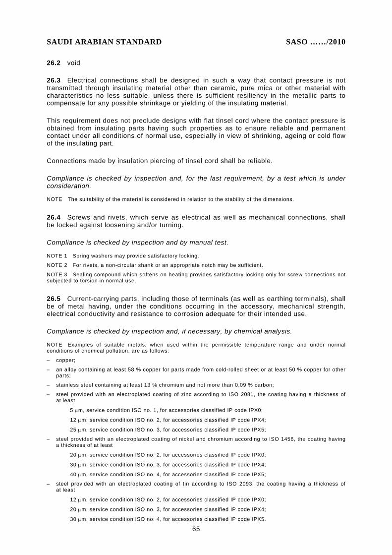
SAUDI ARABIAN STANDARD SASO ……/2010
65
26.2 void
26.3 Electrical connections shall be designed in such a way that contact pressure is not transmitted through insulating material other than ceramic, pure mica or other material with characteristics no less suitable, unless there is sufficient resiliency in the metallic parts to compensate for any possible shrinkage or yielding of the insulating material.
This requirement does not preclude designs with flat tinsel cord where the contact pressure is obtained from insulating parts having such properties as to ensure reliable and permanent contact under all conditions of normal use, especially in view of shrinking, ageing or cold flow of the insulating part.
Connections made by insulation piercing of tinsel cord shall be reliable.
Compliance is checked by inspection and, for the last requirement, by a test which is under consideration.
NOTE The suitability of the material is considered in relation to the stability of the dimensions.
26.4 Screws and rivets, which serve as electrical as well as mechanical connections, shall be locked against loosening and/or turning.
Compliance is checked by inspection and by manual test.
NOTE 1 Spring washers may provide satisfactory locking.
NOTE 2 For rivets, a non-circular shank or an appropriate notch may be sufficient.
NOTE 3 Sealing compound which softens on heating provides satisfactory locking only for screw connections not subjected to torsion in normal use.
26.5 Current-carrying parts, including those of terminals (as well as earthing terminals), shall be of metal having, under the conditions occurring in the accessory, mechanical strength, electrical conductivity and resistance to corrosion adequate for their intended use.
Compliance is checked by inspection and, if necessary, by chemical analysis.
NOTE Examples of suitable metals, when used within the permissible temperature range and under normal conditions of chemical pollution, are as follows:
– copper;
– an alloy containing at least 58 % copper for parts made from cold-rolled sheet or at least 50 % copper for other parts;
– stainless steel containing at least 13 % chromium and not more than 0,09 % carbon;
– steel provided with an electroplated coating of zinc according to ISO 2081, the coating having a thickness of at least
5 µm, service condition ISO no. 1, for accessories classified IP code IPX0;
12 µm, service condition ISO no. 2, for accessories classified IP code IPX4;
25 µm, service condition ISO no. 3, for accessories classified IP code IPX5;
– steel provided with an electroplated coating of nickel and chromium according to ISO 1456, the coating having a thickness of at least
20 µm, service condition ISO no. 2, for accessories classified IP code IPX0;
30 µm, service condition ISO no. 3, for accessories classified IP code IPX4;
40 µm, service condition ISO no. 4, for accessories classified IP code IPX5;
– steel provided with an electroplated coating of tin according to ISO 2093, the coating having a thickness of at least
12 µm, service condition ISO no. 2, for accessories classified IP code IPX0;
20 µm, service condition ISO no. 3, for accessories classified IP code IPX4;
30 µm, service condition ISO no. 4, for accessories classified IP code IPX5.
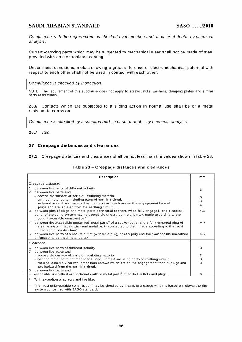
SAUDI ARABIAN STANDARD SASO ……/2010
66
Compliance with the requirements is checked by inspection and, in case of doubt, by chemical analysis.
Current-carrying parts which may be subjected to mechanical wear shall not be made of steel provided with an electroplated coating.
Under moist conditions, metals showing a great difference of electromechanical potential with respect to each other shall not be used in contact with each other.
Compliance is checked by inspection.
NOTE The requirement of this subclause does not apply to screws, nuts, washers, clamping plates and similar parts of terminals.
26.6 Contacts which are subjected to a sliding action in normal use shall be of a metal resistant to corrosion.
Compliance is checked by inspection and, in case of doubt, by chemical analysis.
26.7 void
27 Creepage distances and clearances
27.1 Creepage distances and clearances shall be not less than the values shown in table 23.
Table 23 – Creepage distances and clearances
Description mm
Creepage distance:
1 between live parts of different polarity 2 between live parts and
– accessible surface of parts of insulating material – earthed metal parts including parts of earthing circuit – external assembly screws, other than screws which are on the engagement face of
plugs and are isolated from the earthing circuit
3
3 3 3
3 between pins of plugs and metal parts connected to them, when fully engaged, and a socket-outlet of the same system having accessible unearthed metal partsa, made according to the most unfavourable constructionc
4.5
4 between the accessible unearthed metal partsa of a socket-outlet and a fully engaged plug of the same system having pins and metal parts connected to them made according to the most unfavourable constructionb
4.5
5 between live parts of a socket-outlet (without a plug) or of a plug and their accessible unearthed or functional earthed metal partsa
4.5
Clearance:
6 between live parts of different polarity 3 7 between live parts and
– accessible surface of parts of insulating material – earthed metal parts not mentioned under items 8 including parts of earthing circuit, – external assembly screws, other than screws which are on the engagement face of plugs and
are isolated from the earthing circuit 8 between live parts and – accessible unearthed or functional earthed metal partsa of socket-outlets and plugs.
3 3 3
6 a With exception of screws and the like.
b The most unfavourable construction may be checked by means of a gauge which is based on relevant to the system concerned with SASO standard.

SAUDI ARABIAN STANDARD SASO ……/2010
67
Compliance is checked by measurement on the specimen as delivered.
Socket-outlets are checked when in engagement with a plug and also without a plug.
Distances through slots or openings in external parts of insulating material are measured using a metal foil in contact with the accessible surface other than the engagement face of plugs. The foil is pushed into corners and the like by means of the test probe 11 of IEC 61032, but is not pressed into openings.
NOTE 1 The contribution to the creepage distance of any groove less than 1 mm wide is limited to its width.
NOTE 2 Any air-gap less than 1 mm wide is ignored in computing the total clearance.
27.2 Insulating sealing compound shall not protrude above the edge of the cavity in which it is contained.
Compliance with the requirements is checked by inspection.
28 Resistance of insulating material to abnormal heat, to fire and to tracking
28.1 Resistance to abnormal heat and to fire
Parts of insulating material which might be exposed to thermal stresses due to electric effects, and the deterioration of which might impair the safety of the accessory, shall not be unduly affected by abnormal heat and by fire.
Compliance is checked by the test of 28.1.1 and, in addition, for plugs with pins provided with insulating sleeves, by the test of 28.1.2
28.1.1 Glow-wire test
The test is performed according to IEC 60695-2-10 and IEC 60695-2-11 under the following conditions:
– for parts of insulating material, necessary to retain current-carrying parts, and parts of the earthing circuit of portable accessories in position, by the test made at a temperature of 750 °C;
NOTE 1 Void.
– for parts of insulating material, not necessary to retain current-carrying parts and parts of the earthing circuit in position, even though they are in contact with them, by the test made at a temperature of 650 °C.
If the tests specified have to be made at more than one place on the same specimen, care shall be taken to ensure that any deterioration caused by previous tests does not affect the result of the test to be made.
Small parts, where each surface lies completely within a circle of 15 mm diameter, or where any part of the surface lies outside a 15 mm diameter circle and where it is not possible to fit a circle of 8 mm diameter on any of the surfaces, are not subjected to the test of this subclause (see figure 39 for diagrammatic representation).
NOTE 2 When checking a surface, projections on the surfaces and holes which are not greater than 2 mm on the largest dimension are disregarded.
The tests are not made on parts of ceramic material.
NOTE 3 The glow-wire test is applied to ensure that an electrically heated test wire under defined test conditions does not cause ignition of insulating parts or to ensure that a part of insulating material, which might be ignited by the heated test wire under defined conditions, has a limited time to burn without spreading fire by flame or burning parts or droplets falling down from the tested parts onto the pinewood board covered with a tissue paper.

SAUDI ARABIAN STANDARD SASO ……/2010
68
If possible, the specimen should be a complete accessory.
NOTE 4 If the test cannot be made on a complete accessory, a suitable part may be cut from it for the purpose of the test.
The test is made on one specimen.
The test is made applying the glow-wire once.
In case of doubt, the test shall be repeated on two further specimens.
The specimen shall be positioned during the test in the most unfavourable position of its intended use (with the surface tested in a vertical position).
The tip of the glow-wire shall be applied to the specified surface of the specimen taking into account the conditions of the intended use under which a heated or glowing element may come into contact with the specimen.
The specimen is regarded as having passed the glow-wire test if
– there is no visible flame and no sustained glowing, or if – flames and glowing at the specimen extinguish within 30 s after removal of the glow-wire.
There shall be no ignition of the tissue paper or scorching of the board.
28.1.2 The specimen of a plug with pins provided with insulating sleeves is tested by means of the test apparatus as shown in figure 40.
This test apparatus consists of an insulating plate A and of a metal part B: between these two parts an air space of 3 mm shall be provided and this distance shall be obtained through means which do not impair the air circulation around the pins.
The front surface of the insulating plate A shall be round and flat and have a diameter equal to twice the maximum permissible dimension of the engagement face of the plug given in the relevant SASO standard.
The thickness of this insulating plate shall be 5 mm.
The metal part B shall be of brass and have, for a distance of at least 20 mm, the same shape as the maximum outline of the plug according to the relevant SASO standard.
The rest of this metal part shall be so shaped that the accessory under test is heated through it by conduction, and the heat transmission to the accessory under test by convection or radiation is reduced to a minimum.
A thermocouple shall be inserted at a distance of 7 mm from the front surface of the metal part in a symmetrical position, as shown in figure 40.
The dimensions of the holes for the pins in the metal part B shall be 0,1 mm larger than the maximum dimensions of the pins given in the relevant SASO standard and the distances between the pins shall be the same as those given in the relevant SASO standard; the depth of the holes shall be sufficient.
NOTE 1 The metal part B can be made of two or more component pieces, for hole cleaning purposes.
The specimens are inserted in the test apparatus, placed in the most unfavourable horizontal position, when the test apparatus has reached a steady temperature, measured by means of the thermocouple, of (180 ± 5) °C.

SAUDI ARABIAN STANDARD SASO ……/2010
69
The temperature is maintained for 3 h.
The specimens are then taken out from the test apparatus and are allowed to cool down to room temperature, at which they are maintained for at least 4 h.
The insulating sleeves of the pins of the specimens are then submitted to an impact test in accordance with clause 30 but made at ambient temperature, and subject to visual inspection.
NOTE 2 During visual inspection, no cracks on the insulating sleeves should be visible with normal or corrected vision without additional magnification, and the dimensions of the insulating sleeves should not have changed so as to impair protection against accidental contact.
28.2 Resistance to tracking
For accessories having an IP code higher than IPX0, parts of insulating material retaining live parts in position shall be of material resistant to tracking.
Compliance is checked according to IEC 60112.
Ceramic parts are not tested.
A flat surface of the part to be tested, if possible at least (15 × 15) mm, is placed in a horizontal position.
The material under test shall pass a proof-tracking index of 175 using test solution A with an interval between drops of (30 ± 5) s.
No flashover or breakdown between electrodes shall occur before a total of 50 drops has fallen.
29 Resistance to rusting
Ferrous parts, including covers, shall be adequately protected against rusting.
Compliance is checked by the following test.
All grease is removed from the parts to be tested, using a suitable degreasing agent.
The parts are then immersed for 10 min in a 10 % solution of ammonium chloride in water at a temperature of (20 ± 5) °C.
Without drying, but after shaking off any drops, the parts are placed for 10 min in a box containing air saturated with moisture at a temperature of (20 ± 5) °C.
After the parts have been dried for 10 min in a heating cabinet at a temperature of (100 ± 5) °C, their surfaces shall show no signs of rust.
NOTE 1 Traces of rust on sharp edges and any yellowish film removable by rubbing are ignored.
NOTE 2 For small springs and the like, and for inaccessible parts exposed to abrasion, a layer of grease may provide sufficient protection against rusting. Such parts are subjected to the test only if there is doubt about the effectiveness of the grease film, and the test is then made without previous removal of the grease.

SAUDI ARABIAN STANDARD SASO ……/2010
70
30 Additional tests on pins provided with insulating sleeves
The material of pin-insulating sleeves shall be resistant to the stresses to which it may be subjected at high temperature, likely to occur in conditions approaching bad connection conditions, and at low temperatures in particular conditions of service.
Compliance is checked by means of the following tests:
30.1 Pressure test at high temperature
The specimens are tested by means of the apparatus shown in figure 41. This apparatus has a blade having a round shape (see figure 41b), with a diameter of 6 mm and an edge of 0,7 mm.
The specimens are placed in position as shown in figure 41.
The force applied through the blade is 2,5 N.
The apparatus, with the specimen in position, is maintained for 2 h in a heating cabinet at a temperature of (200 ± 5) °C.
The specimen is then removed from the apparatus and, within 10 s, cooled by immersion in cold water.
The thickness of the insulation remaining at the point of impression is measured and shall not have been reduced by more than 50 % of its original value measured at the start of the test.
NOTE The values 2,5 N and (200 ± 5) °C are provisional.
30.2 Static damp heat test
A set of three specimens is submitted to two damp heat cycles in accordance with IEC 60068-2-30.
After this treatment and after regaining ambient temperature, the specimens are submitted to the following tests:
– insulation resistance and electric strength test, in accordance with clause 17, – abrasion test, in accordance with 24.7.
30.3 Test at low temperature
A set of three specimens is maintained at (–7 ± 2) °C for 24 h.
After regaining ambient temperature, the specimens are submitted to the following tests:
– insulation resistance and electric strength test, in accordance with clause 17; – abrasion test, in accordance with 24.7.
30.4 Impact test at low temperature
The specimens are subjected to an impact test by means of the apparatus as shown in figure 42. The mass of the falling weight is (100 ± 1) g.
The apparatus, on a sponge rubber pad, 40 mm thick, is placed, together with the specimens, in a freezer at a temperature of (–7 ± 2) °C for at least 24 h.

SAUDI ARABIAN STANDARD SASO ……/2010
71
At the end of this period, each specimen in turn, is placed in position, as shown in figure 42, and the falling weight is allowed to fall from a height of 100 mm. Four impacts are applied successively to the same specimen, rotating it through 90° between impacts.
After the test the specimens are allowed to attain approximately room temperature and are then examined.
No cracks of the insulating sleeves shall be visible with normal or corrected vision without additional magnification.
NOTE The cooling period of 24 h, mentioned in the tests of 30.3 and 30.4, includes the time necessary for cooling down the apparatus.
101 EMC requirements 101.1 Immunity Under construction 101.2 Emission Under construction
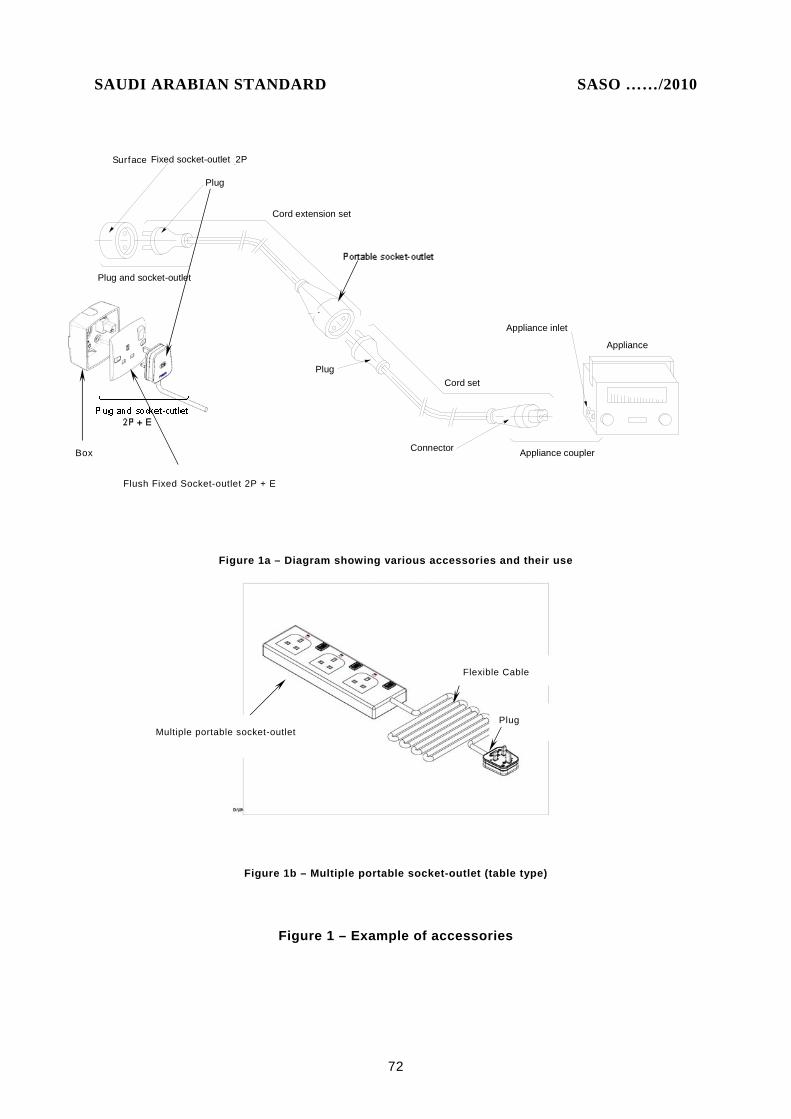
SAUDI ARABIAN STANDARD SASO ……/2010
72
Fixed socket-outlet (2P + E)
Plug
Cord extension set
Plug and socket-outlet
Portable socket-outlet
Connector
Appliance inlet
Appliance
Appliance coupler
Cord setPlug
IEC 1311/02
Figure 1a – Diagram showing various accessories and their use
Figure 1b – Multiple portable socket-outlet (table type)
Figure 1 – Example of accessories
Surface
Box
Flush Fixed Socket-outlet 2P + E
Plug
Flexible Cable
Multiple portable socket-outlet

SAUDI ARABIAN STANDARD SASO ……/2010
73
D D D
g
4,5
2,5
R = 1,25
Terminals without pressure plate Elongated hole terminal Terminals with pressure plateIEC 1313/02
Dimensions in millimetres
Cross-section of conductor accepted by the terminal
mm2
Minimum diameter D
(or minimum dimensions) of
conductor space
mm
Minimum dis- tance g betweenclamping screwand end of con-
ductor when fully inserted
mm
Torque
Nm
One
screw
Two
screws
1a 2a 3a
One screw
Two screws
One screw
Two screws
One screw
Two screws
Up to 1,5
2,5 1,5 1,5 0,2 0,2 0,4 0,4 0,4 0,4
2,5 (circular hole)
3,0 1,5 1,5 0,25 0,2 0,5 0,4 0,5 0,4
2,5 (elongated hole)
2,5 × 4,5 1,5 1,5 0,25 0,2 0,5 0,4 0,5 0,4
4 3,6 1,8 1,5 0,4 0,2 0,8 0,4 0,8 0,4
a The values specified apply to screws covered by the corresponding columns in table 6.
The part of the terminal containing the threaded hole and the part of the terminal against which the conductor is clamped by the screw may be two separate parts, as in the case of terminals provided with a stirrup.
The shape of the conductor space may differ from those shown, provided that a circle with a diameter equal to the minimum specified for D or the minimum outline specified for the elongated hole accepting cross-sections of conductors up to 2,5 mm2 can be inscribed.
Figure 2 – Pillar terminals

SAUDI ARABIAN STANDARD SASO ……/2010
74
D D
DD
DD
A A
A
A
AA
B
B
E
C
C
Optional Optional
OptionalOptional
Optional Optional
C
Screw terminals
Stud terminals
E
IEC 1314/02 Key A Fixed part B Washer or clamping plate C Anti-spread device D Conductor space E Stud
Figure 3a – Screw/stud not requiring washer or clamping plate
Figure 3b – Screw/stud requiring washer, clamping plate or anti-spread device
Cross-section of
conductor accepted by the terminal
mm2
Minimum diameterD of conductor
space
mm
Torque
3a
One screw or stud
Two screws or studs
Up to 1,5
Up to 2,5
Up to 4
1,7
2,0
2,7
0,5
0,8
1,2
–
–
0,5 a The values specified apply to the screws covered by the corresponding columns in table 6. The part which retains the conductor in position may be of insulating material provided the pressure necessary to clamp the conductor is not transmitted through the insulating material.
The second optional space for the terminal accepting cross-section of conductors up to 2,5 mm2 may be used for the connection of the second conductor when it is required to connect two 2,5 mm2 conductors.
Figure 3 – Screw terminals and stud terminals
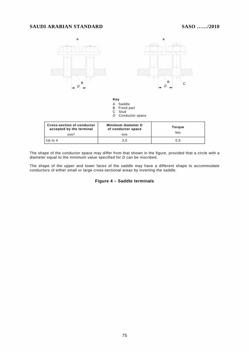
SAUDI ARABIAN STANDARD SASO ……/2010
75
A A
B BD D
C
IEC 1315/02
Key A Saddle B Fixed part C Stud D Conductor space
Cross-section of conductor accepted by the terminal
mm2
Minimum diameter D of conductor space
mm
Torque Nm
Up to 4 3,0 0,5
The shape of the conductor space may differ from that shown in the figure, provided that a circle with a diameter equal to the minimum value specified for D can be inscribed.
The shape of the upper and lower faces of the saddle may have a different shape to accommodate conductors of either small or large cross-sectional areas by inverting the saddle.
Figure 4 – Saddle terminals

SAUDI ARABIAN STANDARD SASO ……/2010
76
Fixed part
D
Fixed part
D
gPart of accessorywith cavity for terminal
IEC 1316/02
Cross-section of conductor accepted by the terminal
mm2
Minimum diameter D of conductor space a
mm
Minimum distance g between fixed part and end of conductor when
fully inserted
mm
Up to 1,5
Up to 2,5
Up to 4
1,7
2,0
2,7
1,5
1,5
1,8
a The bottom of the conductor space must be slightly rounded in order to obtain a reliable connection. NOTE The value of the torque to be applied is that specified in column 2 or 3 of table 6 as appropriate.
Figure 5 – Mantle terminals
IEC 1317/02
Figure 6 – Example of thread-forming screw
IEC 1318/02
Figure 7 – Example of thread-cutting screw

SAUDI ARABIAN STANDARD SASO ……/2010
77
Steel pressure plateForceForce
5 m
in.
Specimen
Steel base
a) b)
IEC 1319/02
Dimensions in millimetres
Figure 8 – Arrangement for compression test of 24.5
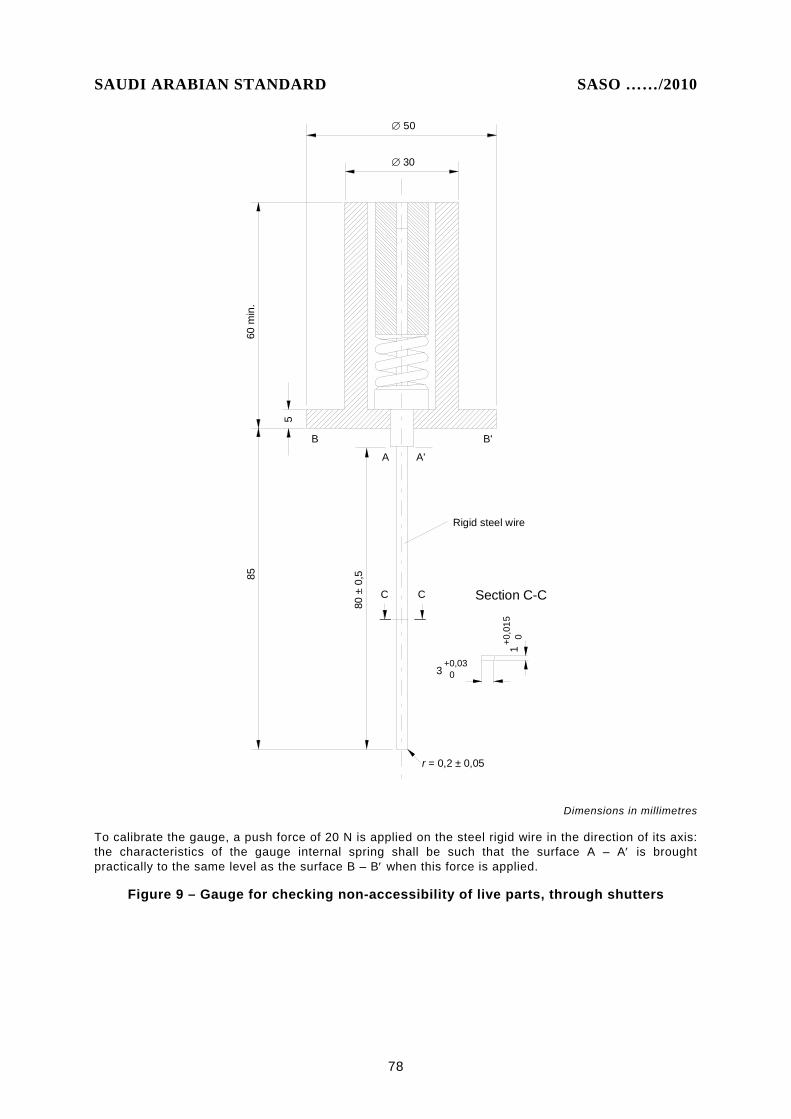
SAUDI ARABIAN STANDARD SASO ……/2010
78
Rigid steel wire
∅ 50
∅ 30
60 m
in.
85
5
80 ±
0,5
3+0,03
0
1+0
,015
0
r = 0,2 ± 0,05
B B'
A A'
C C Section C-C
IEC 1320/02
Dimensions in millimetres
To calibrate the gauge, a push force of 20 N is applied on the steel rigid wire in the direction of its axis: the characteristics of the gauge internal spring shall be such that the surface A – A′ is brought practically to the same level as the surface B – B′ when this force is applied.
Figure 9 – Gauge for checking non-accessibility of live parts, through shutters

SAUDI ARABIAN STANDARD SASO ……/2010
79
∅ 50
∅ 30
60 m
in.
85
5
80 ±
0,5
Rigid steel wire
∅ 1+0,0150
r = 0,05
B B'
A A'
IEC 1321/02
Dimensions in millimetres
To calibrate the gauge, a push force of 1 N is applied on the steel rigid wire in the direction of its axis: the characteristics of the gauge internal spring shall be such that the surface A – A′ is brought practically to the same level as the surface B – B′ when this force is applied.
Figure 10 – Gauge for checking non-accessibility of live parts, through shutters, and of live parts of socket-outlets with increased protection

SAUDI ARABIAN STANDARD SASO ……/2010
80
H ±
15
37,5
Platen
Mass
Bushing
Terminal
IEC 1322/02
Dimensions in millimetres
NOTE Care should be taken that the bushing hole is made in a way which ensures that the force extended to the cable is pure pulling force and that the transmission of any torque to the connection in the clamping means is avoided.
Figure 11 – Arrangement for checking damage to conductors

SAUDI ARABIAN STANDARD SASO ……/2010
81
Figure 12 To Figure 15 – VOID

SAUDI ARABIAN STANDARD SASO ……/2010
82
Steel ball ∅ 20
12
A
B
3
r = 10
12
80
64
64 80
∅ 8,3
∅ 8,2
∅ 0,9 1,8
35
Detail A Detail B(spring)
IEC 1327/02
Dimensions in millimetres

SAUDI ARABIAN STANDARD SASO ……/2010
83
The springs, other than springs B, shall be chosen and adjusted in such a way that:
in the disengaged position they exert a force on the plug carrier as specified in the following table:
Rating
A
Number of poles Force on the plug carrier N
13 and 15 3 8,1
When compressed by one-third of the difference between the length in the disengaged position and the fully compressed length, they exert a force equal to 1,2 times the appropriate maximum withdrawal force specified in clause 22.
Figure 16 – Example of apparatus for breaking capacity and normal operation test

SAUDI ARABIAN STANDARD SASO ……/2010
84
1
1
1
1
2P 2P + 2P + 2P +
2P + N 2P + N +
3P 3P +
3P + N 3P + N +
C C C C
CC
C C
CC
N N
N N
IEC 1328/02
Key 1 Metal support
Figure 17 – Circuit diagrams for breaking capacity and normal operation tests

SAUDI ARABIAN STANDARD SASO ……/2010
85
A
B
C
D
G
F
E
150
550
IEC 1329/02
Dimensions in millimetres
Components
A Mounting plate B Specimen C Test plug D Clamp E Carrier F Principal weight G Supplementary weight
Figure 18 – Apparatus for verification of maximum withdrawal force

SAUDI ARABIAN STANDARD SASO ……/2010
86
Pin
IEC 1330/02
NOTE 1 The mass should be equally positioned around the centreline(s) of the pin.
NOTE 2 Dimensions according to the relevant SASO standard.
Figure 19 – Gauge for the verification of minimum withdrawal force
Specimen
Eccentric
Crank
95 30
160 200
IEC 1331/02
Dimensions in millimetres
Figure 20 – Apparatus for testing cord retention

SAUDI ARABIAN STANDARD SASO ……/2010
87
Device for fixing thesample
Specimen
45° 45°
300
mm
min
.
Weight
IEC 1332/02
An adjustment of the different supports for the accessories by means of a threaded spindle shall be provided according to the explanation in 23.4.
Figure 21 – Apparatus for flexing test

SAUDI ARABIAN STANDARD SASO ……/2010
88
Specimen
Mounting support
Frame
1000
± 1
IEC 1333/02
Dimensions in millimetres
Figure 22 – Impact-test apparatus

SAUDI ARABIAN STANDARD SASO ……/2010
89
1 2 3
4
5
7,5
M4 27
7∅ 11,5
3
∅ 2
0
∅ 1
0
57,5
14
∅ 1
0
R = 10
∅ 1
1,5
∅ 8
5
48
10 5 13
7
M4
M4
∅ 1
5
∅ 1
1,5
5514
R = 5
M4
5
120°
4
5
1
2
3IEC 1334/02
Key
Polyamide , , , Steel Fe 360 Dimensions in millimetres
Figure 23 – Details of the striking element
y
200 min.
2
8
7
175
A
A Sheet of plywood
Pivot
A-A
+10 0
175
+10 0
35 ± 2
45°
45°
7
155
± 1
175 ± 1
IEC 1335/02
Dimensions in millimetres
Figure 24 – Mounting support for specimens

SAUDI ARABIAN STANDARD SASO ……/2010
90
Pivot
Sheet of plywood
Specimen
P O Q
Pivot
Sheet of plywood
Specimen
OR S90°
Sheet of plywood
Specimen Specimen
T UV Z
60° 60° 60° 60°
Sheet of plywood
26a) 26b)
26c) 26d) IEC 1337/02
Application of the blows
Sketch Total number of blows Points of application
26a) 3
One at the centre
One between O and P a
One between O and Q a
26b) 2 One between O and R a
One between O and S a
26c) 2 One on the surface T a
One on the surface U a
26d) 2 One on the surface V a
One on the surface Z a a The blow is applied to the most unfavourable point.
Figure 26 – Sketches showing the application of the blows

SAUDI ARABIAN STANDARD SASO ……/2010
91
∅ 10,5
A A
R = 300Sample
Falling weight1 000 ± 2 g
Steel intermediatepiece 100 g
∅ 20 100
40Steel support10 ± 1 Kg
Slightly rounded edges8,6
8,6 8,6
Section A-A
IEC 1338/02
Dimensions in millimetres
Figure 27 – Apparatus for impact test at low temperature of 24.4
A
ACarrier
Clamp
Specimen
10°
Weight
BeamPivot
Weight
Beam
Steel wire1
6Plug in
Enlarged part of section A-A showing steel wire
Steel wire
IEC 1339/02
Dimensions in millimetres
Figure 28 – Apparatus for abrasion test on insulating sleeves of plug pins

SAUDI ARABIAN STANDARD SASO ……/2010
92
2 250Specimen
750
IEC 1340/02
Dimensions in millimetres
Figure 29 – Arrangement for mechanical strength test on multiple portable socket-outlets
Steel plate
P Section A-A
d1
d 2
3 ± 0,25
3 ± 0,25
IEC 1341/02
Dimensions in millimetres Key P Traction
Figure 30 – Example of test arrangement to verify the fixation of pins in the body of the plug

SAUDI ARABIAN STANDARD SASO ……/2010
93
Face A
30 min.
5 30 ±
0,0
1
7 ±
0,01Face C
Face B
5 ±
0,01
10° ± 5'45° ± 5'
10 ± 1
IEC 1343/02
Dimensions in millimetres
Figure 32 – Gauge (thickness about 2 mm) for the verification of the outline of covers

SAUDI ARABIAN STANDARD SASO ……/2010
94
Mounting surface
Socket-outlet
Surface support
* Spacing piece
Mounting surface
Mounting surface
Socket-outlet
Socket-outlet
IEC 1344/02
Dimensions in millimetres
* Spacing piece having the same thickness as that of the supporting part.
Figure 33 – Examples of application of the gauge of figure 32 on covers fixed without screws on a mounting surface or supporting surface

SAUDI ARABIAN STANDARD SASO ……/2010
95
1515
15
X
Y
X
Y
X
Y
X
Y
X
Y
Y
X≤ 1
55
5
a) d)
b) e)
c) f)IEC 1345/02
Dimensions in millimetres
Cases a) and b) do not comply.
Cases c), d), e) and f) comply (compliance shall, however, also be checked with the requirements of 24.18, using the gauge shown in figure 35).
Figure 34 – Examples of application of the gauge of figure 32 in accordance with the requirements of 24.17

SAUDI ARABIAN STANDARD SASO ……/2010
96
100 min.
∅ 2
,5+
0,05
0
Right-angled sharp edges
Test rod (metal)
IEC 1346/02
Dimensions in millimetres
Figure 35 – Gauge for verification of grooves, holes and reverse tapers
Socket outlet
Mounting surface
IEC 1347/02
Figure 36 – Sketch showing the direction of application of the gauge of figure 35

SAUDI ARABIAN STANDARD SASO ……/2010
97
SphericalSpecimenR = 2,5 mm
IEC 1348/02
Dimensions in millimetres
Figure 37 – Ball pressure test apparatus
Guides
Moving jaw
Specimen
Fixed jaw
R = 2,5R =
25
Force
R =
25
15,4
15,0
50 m
in.
IEC 1349/02
Dimensions in millimetres
Figure 38 – Apparatus for compression test for the verification of resistance to heat of 25.4

SAUDI ARABIAN STANDARD SASO ……/2010
98
15 mm
15 mm
8 mm
8 mm
Specimen
Specimen
To be tested
No test is requiredIEC 1350/02
Figure 39 – Diagrammatic representation of 28.1.1
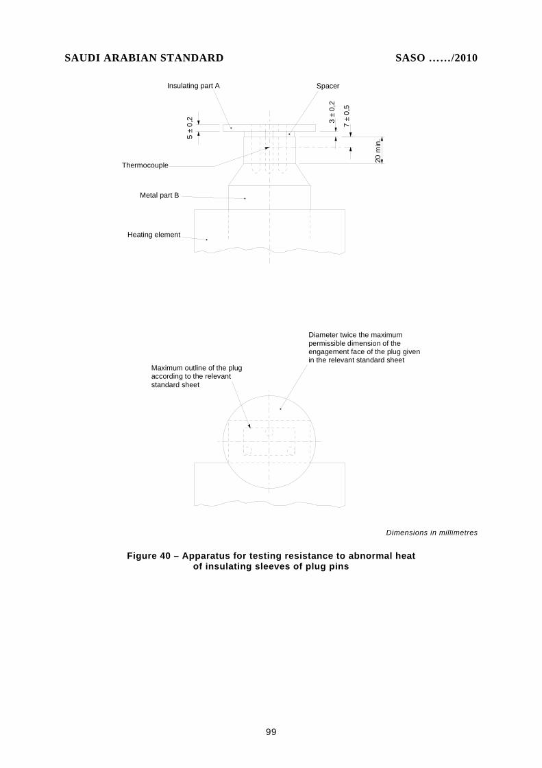
SAUDI ARABIAN STANDARD SASO ……/2010
99
5 ±
0,2
Insulating part A Spacer
3 ±
0,2
7 ±
0,5
20 m
in.
Thermocouple
Metal part B
Heating element
Maximum outline of the plugaccording to the relevantstandard sheet
Diameter twice the maximumpermissible dimension of theengagement face of the plug givenin the relevant standard sheet
IEC 1351/02
Dimensions in millimetres
Figure 40 – Apparatus for testing resistance to abnormal heat of insulating sleeves of plug pins

SAUDI ARABIAN STANDARD SASO ……/2010
100
∅ 6
Specimen Support
0,7
IEC 1352/02
Dimensions in millimetres
Figure 41 – Apparatus for pressure test at high temperature
∅ 10,5
A A
R = 300Specimen
Falling weight1 000 ± 2 g
Steel intermediatepiece 100 g
∅ 20 100
40Steel support10 ± 1 Kg
Slightly rounded edges8,6
8,6 8,6
Section A-A
20 m
in.
∅ 6
IEC 1353/02 Dimensions in millimetres
Figure 42 – Impact test apparatus on pins provided with insulating sleeves

SAUDI ARABIAN STANDARD SASO ……/2010
101
§ 21 Normal operation10 000 strokes with shutter - with current
Tests OK?
Is it possible to continue the test?
On tested samples To complete normal operation test§ 19 Temperature rise test§ 17.2 Electric strength at 1 500 V
On new samples (see 5.4)10 000 strokes with shutters - without current
Gauges: Figure 9 20N – Figure 10 1N
On new samples (see 5.4) 10 000 strokes without shutters - with current§ 19 Temperature rise test § 17.2 Electric strength at 1 500 V
Tests OK?
On new samples (see 5.4) 10 000 strokes
MADE BY HAND with shutters - with current
Gauges: Figure 9 20N – Figure 10 1N§ 19 Temperature rise test § 17.2 Electric strength at 1 500 V
Tests OK?
Continue testing Reject
On tested samples § 19 Temperature rise test § 17.2 Electric strength at 1 500 V
YES NO
YES NO
YES NO
YES NO
1
Gauges: Figure 9 20N – Figure 10 1N
Tests OK?YES NO
Reject
2
3
IEC 912/06
Figure 43 – Test procedures for normal operation (see Clause 21)

SAUDI ARABIAN STANDARD SASO ……/2010
102
Annex A
Safety-related routine tests for factory-wired portable accessories
(protection against electric shock and correct polarity)
A.1 General remarks
All factory-wired plugs and portable socket-outlets shall be subjected to tests specified in clauses A.2, A.3 and A.4.
The test equipment or manufacturing systems shall be such that failed products are either made unfit for use or separated from satisfactory products in such a way that they cannot be released for sale.
NOTE "Unfit for use" means that the accessory is treated in such a way that it cannot fulfil the intended function. It is, however, accepted that repairable products (by a reliable system) may be repaired and re-tested.
It shall be possible by process or manufacturing system to identify that accessories released for sale have been subjected to all the appropriate tests.
The manufacturers shall maintain records of the tests carried out which show
– the type of product; – the date of test; – the place of manufacture (if manufactured in more than one place); – the quantity tested; – the number of failures and actions taken, i.e. destroyed/repaired.
The test equipment shall be checked before and after each period of use and for periods of continuous use, at least once every 24 h. During these checks the equipment shall show that it indicates faults when known faulty products are inserted or simulated faults are applied.
Products manufactured prior to a check shall only be released for sale if the check is found satisfactory.
Test equipment shall be verified (calibrated) at least once a year. Records shall be kept of all checks and any adjustments found necessary.
A.2 Polarized systems, phase (L) and neutral (N) – correct connection
For polarized systems the test shall be made using SELV applied for a period of not less than 2 s:
NOTE 1 The period of 2 s may be reduced to not less than 1 s on test equipment with automatic timing.
– for plugs and portable socket-outlets, between the remote end of the L and N conductors of the flexible cable independently, and the corresponding L and N pin or contact of the accessory;
– for cord extension sets, between the L and N pin at one end of the flexible cable and the corresponding L and N contact at the other end of the flexible cable.
SAUDI ARABIAN STANDARD SASO ……/2010
103
Polarity shall be correct.
A.3 Earth continuity
The test shall be made using SELV applied for a period of not less than 2 s:
NOTE 1 The period of 2 s may be reduced to not less than 1 s on test equipment with automatic timing.
– for plugs and portable socket-outlets, between the remote end of the earth conductor of the flexible cable, and the earth pin or contact of the accessory, as appropriate;
– for cord extension sets, between the corresponding earth pin or earth contact of the accessory at each end of the flexible cable.
Continuity shall be present.
A.4 Short-circuit/wrong connection and reduction of creepage distance and clearances between phase (L) or neutral (N) to earth ( )
The test shall be made by applying at the supply end, e.g. to a plug, for a period of not less than 2 s:
– 1 250 V ± 10 % for accessories having a rated voltage of 127 V; – 2 000 V ± 10 % for accessories having a rated voltage of 220 V; NOTE 1 The period of 2 s may be reduced to not less than 1 s on test equipment with automatic timing.
or – for all rated voltages, by applying an impulse voltage test using a 1,2/50 µs waveform of
4 kV peak value and three impulses for each pole, with intervals of not less than 1 s:
• between L and ,
• between N and .
NOTE 2 L and N may be connected together for this test.
No flashover shall occur.

SAUDI ARABIAN STANDARD SASO ……/2010
104
Annex B
VOID

SAUDI ARABIAN STANDARD SASO ……/2010
105
Annex C (informative)
Alternative gripping tests
Gripping test C1
Prior to testing, the reference plug shown in Figure C.1 shall be cleaned with a metal cleaner.
The reference plug, the plug to be tested, and the hands of each person conducting the test shall be washed with soap and water, rinsed, and then dried.
The test apparatus consists of a measuring device equipped with a means to securely attach both the reference plug and the plug to be tested, in a manner that reduces the likelihood of rotational movement during the pulls. An engagement face simulating the use of a plug in a socket-outlet of the same system, having an opening for the plug pins, shall be secured to the movable member.
NOTE Other methods for measuring force may be used.
The mounting arrangements for the plug being tested shall be such that the face of the plug is flush with the faceplate.
A typical apparatus is shown in Figure C.2.
The plug to be tested with the flexible cable cut off close to the plug shall be securely attached to the test apparatus.
The person performing the test shall grip the plug to be tested, with either hand in a manner intended to apply the maximum pull force.
A steady straight pull shall be applied until the plug pulls free from the person’s hand.
The person applying the force shall not view the force indicator during the pull.
The maximum pull force applied during the pull shall be recorded.
Immediately following the pull test, the reference plug shall be attached to the test apparatus and a comparison pull made using the same hand.
The maximum pull force shall be recorded.
The ratio of the force for the plug under test, to that for the reference plug shall be calculated and recorded.
The comparison pull procedure described above shall be repeated on the same plug an additional two times by the same person.
The ratio for each pair of pulls (test plug/reference plug) shall be calculated and recorded.

SAUDI ARABIAN STANDARD SASO ……/2010
106
One person shall test three plugs (total nine comparison pulls) as described above with the ratio for each pair of pulls being calculated and recorded for all three plugs. If the ratio of the pull force (plug under test/reference plug) for each pair of pulls resulting from the tests carried out by this person is 0,8 or greater, the test shall be stopped and the results considered acceptable.
If the ratio is lower than 0,8, two additional people shall test three plugs each (for a total of nine comparison pulls per person), as described above.
The ratio for each pair of pulls (plug under test/reference plug) shall be calculated and recorded.
The results are considered acceptable if all of the following conditions are met:
a) the ratio for each pair of pulls (test/reference plug) is 0,55 or greater for at least two pulls (of the three pulls performed) on each plug,
b) at least two (of the three) plugs tested by each person comply with item a), and c) at least two persons' test results comply with item b).
If only one person obtains results that comply with item b) then at the manufacturer's request, two persons not previously involved in the testing may test three plugs each as previously described.
The results are considered acceptable if both of the additional persons' test results comply with items a) and b).
No result should be lower than the maximum withdrawal force for the relevant socket-outlet as specified in Table 16.

SAUDI ARABIAN STANDARD SASO ……/2010
107
15,9 ± 0,1
20,6 ± 0,1
R9,7 ± 0,2R2,4 ± 0,1
25,4 ± 0,225
,4 ±
0,2
12
,7±
0,2
1
Dimensions in millimetres
Material: for example heat-treated steel.
Surface roughness of the gripping surface: between 0,6 µm and 0,8 µm.
1 Hole for retaining pins.
NOTE The dimensions are to suit the test specimen and those of Figure C.2.
Figure C.1 – Reference plug for gripping test

SAUDI ARABIAN STANDARD SASO ……/2010
108
E
H
D
E
P
E Simulated engagement face
H Hole for introduction of fixing means
P Holes for pins for retention of fixing means
D Measuring device
NOTE The figure is for guidance only and is not intended to govern the design of the test apparatus.
Figure C.2 – Example of the test apparatus for plug gripping test

SAUDI ARABIAN STANDARD SASO ……/2010
109
Gripping test C2
This test consists of a verification of one of the following characteristics of the plug under test:
– the plug has a usable length for gripping of at least 55 mm in axial direction; or
– the plug has such indent(s) that a ball with a diameter of (12 ± 0,1) mm can penetrate radially into the body at least 2 mm from two opposite directions or at least 4 mm from one direction; or
– the plug has special means for withdrawal (e.g. hooks, rings).
The results are considered acceptable if at least one of the above conditions is fulfilled.

SAUDI ARABIAN STANDARD SASO ……/2010
110
Bibliography
IEC/TR3 60083:1997, Plugs and socket-outlets for domestic and similar general use standardized in member countries of IEC
IEC 60320 (all parts), Appliance couplers for household and similar general purposes
IEC 60364-4-41:2001, Electrical installations of buildings – Part 4-41: Protection for safety – Protection against electric shock
IEC 60417-1:2000, Graphical symbols for use on equipment – Part 1: Overview and application
IEC 60670:1989, General requirements for enclosures for accessories for household and similar fixed electrical installations
IEC 61540:1999, Electrical accessories – Portable residual current devices without integral overcurrent protection for household and similar use (PRCDs)
___________

SAUDI ARABIAN STANDARD SASO ……/2010
111
SAFETY REQUIREMENTS FOR CORD EXTENSION SETS
The preliminary draft No. 14047 of this standard has been developed by the work team composed of:
Name Agency
1. Eng. Basem Hani Salameh Al-Fanar Electrical Systems
2. Eng. Monir AlSayed Hussin SASO
3. Eng. AbdulRahman Al-AbdulKreem SASO
The draft standard was studied and approved to be circulated to the concerned bodies in the meeting No. (60). It has been adopted, in its present form, by the following members of Technical Committee No. (5).
Name Agency
1. Dr. Abdulhameed A. Al-Ohaly King Saud University
2. Dr. Yusuf A. Al Turky King Abdulaziz University
3. Eng. Basem Salameh Al-Fanar Electrical Systems
4. Eng. Walid Hilal Omrania and Associated
5. Eng. Mohammad M. Sameery Al-Amr Group
6. Eng. M. Bafil Al-Amoudy Honeywell
7. Eng. Asaad Al-Turkmany Saudi Consultant
8. Eng. Monir Hussin S A S O
9. Eng. Amr Mohamed Mohamed S A S O