Embed Size (px)
Citation preview

SANDVIK Roadheader MR340, MR360 – (ATEX approved)
Page 1 of 28
www.sandvik.com
Technical description-MR340 MR360 ATEX approved Specification.500.Rev1
The model MR360 is identical to the model MR340 with the only difference that it allows to cut a higher profile (see technical data and cutting profile).
The increased cutting height is achieved by implementing a turret elevation and a boom extension.

SANDVIK Roadheader MR340, MR360 – (ATEX approved)
Page 2 of 28
www.sandvik.com
Technical description-MR340 MR360 ATEX approved Specification.500.Rev1
Table of Content
1. Machine Layout MR340 .......................................................................................... 3 2. Machine Layout MR360 .......................................................................................... 4 3. Technical Data MR340/MR360 ............................................................................... 5 4. Cutting Profile .......................................................................................................... 7 5. Description of assembly groups .............................................................................. 8 5.1 Cutter boom Module ................................................................................................ 9 5.2 Cutter boom .......................................................................................................... 10 5.3 Cutter Head ........................................................................................................... 11 5.4 Cutter Gearbox Type XL (for frequency 50 [Hz]) ................................................... 12 5.5 ITP Spraying System ............................................................................................ 13 5.6 Sector control system ............................................................................................ 14 5.7 Turret .................................................................................................................... 15 5.8 Loading Assembly ................................................................................................. 16 5.9 Double chain conveyor .......................................................................................... 18 5.10 Crawler Track Assembly ....................................................................................... 19 5.11 Frame .................................................................................................................... 21 5.12 Electrical Equipment ............................................................................................. 22 5.13 Hydraulic system ................................................................................................... 24 5.14 Operators Stand .................................................................................................... 25 5.15 Cooling and Water Supply System ........................................................................ 26 5.16 Lubrication System ................................................................................................ 28
Disclaimer
• SANDVIK MINING AND CONSTRUCTION shall not be held responsible for any errors or omissions contained in this document and reserves the right to make changes or additions without prior notice due to continual product developments.
• The images, pictures, and illustrations found in this document are for illustration purposes only, and do not necessarily represent the exact products, services, or ideas in the context they are found in. It is the buyer’s responsibility prior to purchase to clarify with the seller, SANDVIK MINING AND CONSTRUCTION, exactly what products and services are being provided for to purchase.

SANDVIK Roadheader MR340, MR360 – (ATEX approved)
Page 3 of 28
www.sandvik.com
Technical description-MR340 MR360 ATEX approved Specification.500.Rev1
1. Machine Layout MR340

SANDVIK Roadheader MR340, MR360 – (ATEX approved)
Page 4 of 28
www.sandvik.com
Technical description-MR340 MR360 ATEX approved Specification.500.Rev1
2. Machine Layout MR360

SANDVIK Roadheader MR340, MR360 – (ATEX approved)
Page 5 of 28
www.sandvik.com
Technical description-MR340 MR360 ATEX approved Specification.500.Rev1
3. Technical Data MR340/MR360
Cutting system [mm] Cutting height above track level, max 4.870 5.060 Cutting width, horizontal [mm] 7.450 7.600 Undercut below track level [mm] 205 280 Cross section, above track level [m²] 34 35 Adjustment of loading table
above floor level [mm] 710 710 below floor level [mm] 120 120
Spraying system [ITP]
water quantity min. [l/min] 39 39 water pressure min. [l/min] 15 15
Navigable Area of Application [m] Cone radius [m] 25 25 Basis radius [°] 15 15 Slope side in rock, max. [°] ± 5 ± 5 Slope side in coal, max. [°] ± 8 ± 8 Incline/Decline, max. [°] ± 18 ± 18 Incline/Decline with the use of anchoring device [°] ± 32 ± 32 Geometric Characteristics Slewing of cutter boom [°] ± 45 ± 45 Vertical lifting from horizontal upwards [°] 63 58 Vertical lowering from horizontal downwards [°] 22 27 Forces Traction force per track [kN] 358 358 Cutter boom cylinders (including of gravity) [kN]
lifting [kN] 169 169 lowering [kN] 215 215 horizontal [kN] 69 69
General MR340 MR360 Total weight (approx.) [t] 55 56 Total length [m] 10.3 10.4 Height over turret [mm] 2.045 2.165 Height over driver stand [mm] 2.885 2.885 Machine width over tracks [mm] 2.600 2.600 Machine width without loading table [mm] 3.250 3.250 Loading table width [mm] 4720 to 5120 4720 to 5120 Crawler track width [mm] 600 600 Machine ground pressure [MPa] 0.15 0.15 Ground clearance [mm] 240/420 240/420

SANDVIK Roadheader MR340, MR360 – (ATEX approved)
Page 6 of 28
www.sandvik.com
Technical description-MR340 MR360 ATEX approved Specification.500.Rev1
Technical Data MR340/MR360
Loading System MR340 MR360 Lobster arms [pcs] 2 2 Loading capacity [m³] 300 300
Conveyor System (double conveyor) With of conveyor [mm] 600 600 Conveying capacity [m³] 300 300 Headroom between conveyor and turret mm 420 520
Electrical System Voltage [V] 1000 1000 Frequency [Hz] 50 50 Total installed power [kW] 357 357 Cutter motor water cooled
nominal power [kW] 200 200 nominal torque [Nm] 1286 1286
Hydraulic motor water cooled nominal power [kW] 70 70 nominal torque [Nm] 455 455
Loader motor water cooled nominal power (2 x each) [kW] 36 36 nominal torque [Nm] 237 237
Booster pump motor air cooled nominal power kW] 15 15 nominal torque [Nm] 98 98
Hydraulic system (load sensing) Hydraulic pumps [pcs] 3 3 Filtration system [l/min) 1300 1300 Mineral hydraulic fluid [l] 700 700 Nonflammable hydraulic fluid [l] 700 700 Speeds Tramming speed [m/min] 0 – 8.8 0 – 8.8 Speed of cutter head [m/s] 2.3 2.3 Slewing speed cutter boom [m/s] 0.24 0.24 Conveying speed [m/s] 1.1 1.1

SANDVIK Roadheader MR340, MR360 – (ATEX approved)
Page 7 of 28
www.sandvik.com
Technical description-MR340 MR360 ATEX approved Specification.500.Rev1
4. Cutting Profile
MR340
All dimensions in [mm] min 3.2 m high, min. 5.5 m width
MR360
All dimensions in [mm] min. 3.3 m high, min. 5.5 m width
A floor level ~ 34 m2
~ 4100
~ 6100
~ 7450~
205
~ 48
70
floor levelcutting beloe flor level
~ 4300
~ 6100
~ 7600
5060
~ 2
80
A floor level ~ 35 m2
floor levelcutting beloe flor level

SANDVIK Roadheader MR340, MR360 – (ATEX approved)
Page 8 of 28
www.sandvik.com
Technical description-MR340 MR360 ATEX approved Specification.500.Rev1
5. Description of assembly groups
The basis machine of the Sandvik Roadheader consists of the following main components:
1 Cutter boom with cutter head 7 Electrical equipment 2 Turret 8 Hydraulic equipment 3 Loading table with lobster arms 9 Operator stand 4 Chain conveyor 10 Lubrication system 5 Crawler tracks 11 Spraying system 6 Frame 12 Working platform, Arch lifting device
(Option) 6.1 Rear stabilizer
9
2
12
11
1
10
6
6.1
7
4
3
5
8

SANDVIK Roadheader MR340, MR360 – (ATEX approved)
Page 9 of 28
www.sandvik.com
Technical description-MR340 MR360 ATEX approved Specification.500.Rev1
5.1 Cutter boom Module
The cutter boom module comprises the cutter boom base, the cutter motor, the coupling, the cutter gear, the cutter head and if included the spraying system.
1 Cutter boom base 4 Cutter gear 2 Cutter motor 5 Cutter head 3 Coupling 6 ITP spraying system

SANDVIK Roadheader MR340, MR360 – (ATEX approved)
Page 10 of 28
www.sandvik.com
Technical description-MR340 MR360 ATEX approved Specification.500.Rev1
5.2 Cutter boom
1 Cutter boom base A steel construction mounted to the turret. It is used to support the motor and attaches the vertical pivoting cylinders.
2 Cutter motor Self supporting design, water cooled. 3 Coupling Elastic bolt-coupling serves to transfer energy from the motor to
the gears. 4 Cutter gear 3-stage, bevel- spur- planetary gear of compact design directly
flange mounted to the motor. Stub shafts of the drive sealed with slide ring packing. Bevel gear drive sealed with radial shaft packing ring. Change of bevel gear stages makes various speeds possible. Cutter transmission is available in two designs: Dry transmission: If the machine is used with external spraying system only. Wet transmission: With integrated water channels for supplying the cutter head.
5 Cutter head Consists of two cutter head halves, which are attached to the stub shafts of the drive out stage of the cutter transmission. The cutter head halves are connected to each other via multiple spline shafts.
6 Spraying system The machine is equipped with a spraying system, using specific “ITP” hollow cone spray nozzles (Incentive Temperature Potential). The system consists of spraying nozzles for the cutter head and for the loading table

SANDVIK Roadheader MR340, MR360 – (ATEX approved)
Page 11 of 28
www.sandvik.com
Technical description-MR340 MR360 ATEX approved Specification.500.Rev1
5.3 Cutter Head
Depending on the geological conditions there a different cutter heads available. For standard applications, the cutter head R250WZ-TC50 with 50 pick holders (type: EF58) is recommended.
The R250-TC50 is a cutter head for medium hard to hard cutting conditions, like shale, sandy shale, sandstone, etc. The pick holder system EF58 is a heavy-duty tool holder with changeable tapered bushing.
The cutter head is fastened to the gearbox with cylinder bolts and a spline for torque transmission. This arrangement allows easy and quick exchange of cutter head halves.
Type R250WZ-TC50 Optimum range of operation Medium hard stone-shale and coal — 50 - 100 [MPa]
uniaxial compressive strength. (UCS) Tooled with 2 x 50 pick boxes suitable for 38 mm shank-diameter
picks. Locked by 1 clip-ring each in the pick holder Used with cutter gear box type XL Diameter 1050 [mm] Cutting speed 2.34 [m/s] = at 50 [Hz] Slewing speed 0.26 [m/s] = at 50 [Hz]

SANDVIK Roadheader MR340, MR360 – (ATEX approved)
Page 12 of 28
www.sandvik.com
Technical description-MR340 MR360 ATEX approved Specification.500.Rev1
5.4 Cutter Gearbox Type XL (for frequency 50 [Hz])
Type XL (wet version)
1 Input bevel gear stage 5 Input shaft seal 2 Spur gear stage 6 Breather valve 3 Output planetary gear stage 7 Oil pump 4 Rotating mechanical seal
Power Input speed (rpm) Output torque Gear ratio Output speed (rpm)
[kW] [min-1] [Nm]
[min-1]
230 1485
51756 34.619 42.46
The gearbox consists of one spur gear stage, one bevel gear stage and one planetary gear stage on both output sides. All mating surfaces are sealed with suitable sealing compounds (Loctite or similar). The input shaft bearing is provided with shaft seals, the output shaft bearing is sealed with rotating mechanical seals.
The advanced gearing design ensures a high life expectancy of the cutter gear box.

SANDVIK Roadheader MR340, MR360 – (ATEX approved)
Page 13 of 28
www.sandvik.com
Technical description-MR340 MR360 ATEX approved Specification.500.Rev1
5.5 ITP Spraying System
The primary method of ignition prevention of the ITP system is by means of ventilation of the cutting zone. This is achieved by specifically designed and approved arrangements of hollow cone sprays (so called “ITP” nozzles - “ITP” stands for “Incendive Temperature Potential”) designed to direct fresh ventilation air into the top of the cutting zone to expel methane from the cut into the area below the cutting jib. This area, in turn, is ventilated by further sprays to ensure rapid dilution and removal from the face of the heading in conjunction with the auxiliary ventilation system, providing the fresh air over the top of the machine. A typical spray arrangement is shown in the picture below:
Water requirements: (to be provided by customer)
The nozzles employed in the system were optimized for their ability to move air whilst maintaining orifice sizes that would not be subject to a significant problem with blockage.
For dust control the system promotes the rapid clearance of dust from the face area: Dust generated by the cutting process is captured by the water mist. The water used by the sprays also wets the cut material, reducing further emission of dust from the cut material during loading, transfer and conveying process.
Quantity [l/min] 39 Incoming pressure [bar] min. 10 -
max. 18 Incoming temperature [°C] max. 35

SANDVIK Roadheader MR340, MR360 – (ATEX approved)
Page 14 of 28
www.sandvik.com
Technical description-MR340 MR360 ATEX approved Specification.500.Rev1
5.6 Sector control system
The cutter system incorporates a well proven sectional controlled pick flushing system, which operates with approximately 35 [bar]. Its function allows the intermitting control for spraying to each pick (tool-system). The sectional control is integrated in the cutter head and its connection to the cutter gear. The water flow becomes intermitted by a control disk. Therefore a water reduction of nearly 50 [%] is possible. Additionally the control disk takes care for a free flow to the jets in a prefixed sector of 140 degree. Selected into this sector each pick, standing in direction to the cutting face, is supplied with water.
1 Cutter pick 4 Nozzle 2 Conical bushing 5 Plug (bushing extraction) 3 Filter plug
Sector control system Pick holder for internal pick flushing system

SANDVIK Roadheader MR340, MR360 – (ATEX approved)
Page 15 of 28
www.sandvik.com
Technical description-MR340 MR360 ATEX approved Specification.500.Rev1
5.7 Turret
The turret is used to move the cutter boom in vertical and horizontal direction. It is bolted to the frame. A disc bearing ensures that very little vibrations occur during operation, even when difficult conditions are experienced.
Horizontal pivoting is achieved with a rack and ring gear arrangement powered by four integrated hydraulic cylinders, providing a constant slewing speed all across the face.
The pivoting range is approx. 45 [°] to each side, right and left.
The vertical pivoting is achieved with the aid of two hydraulic cylinders which are attached to the cutter boom and the turret. The vertical pivoting range is approx. 85 [°].
1 Housing of disk-bearing lower part 4 Horizontal slewing cylinders 2 Frame bridge 5 Sprocket 3 Vertical pivot cylinder 6 Rack
1
2
3
4
4
5
6

SANDVIK Roadheader MR340, MR360 – (ATEX approved)
Page 16 of 28
www.sandvik.com
Technical description-MR340 MR360 ATEX approved Specification.500.Rev1
5.8 Loading Assembly
The loading assembly consists of the loading table (“apron”) which can be raised and lowered hydraulically, the two loader transmissions and the lobster arms.
The loading table is of heavy-duty design with a basic width of 2800 [mm].
Optionally, there are loading table extensions for different widths available, either fixed extensions or hydraulically operated variable extensions. At basis machine is a variable loading table extension 4.72 to 5.12 m included.
The entire upper surface of the loading table which is in contact with the loaded material, is covered with 10 [mm] thick, wear resistant plates.
The loading table is also used to stabilize the machine during cutting with its two hydraulic cylinders.
The two lobster arms move the material from the loading table into the chain conveyor. The lobster arms are also protected with high wear resistant plates.
Each lobster arms is driven by a 36 [kW] water-cooled electric motor via spur gear stage and bevel-gear stage. The motors are completely sealed to avoid entering of water.
1 Loading table 2800 [mm] 4 Cylinder (2x) apron lifting / lowering 2 Loader gear (2x) 5 Apron extension inflexible (2x) 3 Lobster arm (2x) 6 Conveyor front part
1
2
3
4
56

SANDVIK Roadheader MR340, MR360 – (ATEX approved)
Page 17 of 28
www.sandvik.com
Technical description-MR340 MR360 ATEX approved Specification.500.Rev1
Loader Drive Assembly
The loader gear consists of the spur gear stage and bevel gear stage to the output drive. All mating surfaces are sealed by suitable sealing compounds (LOCTITE or similar) against oil penetration. The input shaft bearing is provided with a shaft seal, the driven shaft bearings are sealed with rotating mechanical seals. The loading star is directly mounted on the output side of the loader gear box. Each of the two loader gear boxes is driven by a 36 [kW] electric motor.
1 E-Motor 5 Rotating mechanical seal 2 Coupling 6 Bevel gear 3 Input shaft seals 7 Rotating mechanical seal 4 Drive shaft for sprocket
Input power [kW] 36 Input speed (rpm) [min-1] 1445 Output torque chain conveyor [Nm] 1478 Transmission ratio chain conveyor [i] 17.48 Output torque spinners [i] 4807 Output speed chain conveyor (rpm) [min-1] 72.7 Output speed spinners (rpm) [min-1] 30.1

SANDVIK Roadheader MR340, MR360 – (ATEX approved)
Page 18 of 28
www.sandvik.com
Technical description-MR340 MR360 ATEX approved Specification.500.Rev1
5.9 Double chain conveyor
The chain conveyor is arranged in the center of the machine. It transports the material picked up by the two lobster arms to the rear end of the machine, using a double chain conveying system.
The chain is a standard continuous miner flight chain, size 19 x 64.5 [mm].
The chain conveyor is driven via the loader transmissions and E-Motors.
The surface of the chain conveyor which is in contact with the transported material is protected with 10 [mm] thick, wear resistant plates.
The discharge end of the double chain conveyor is high enough above the track level to allow easy loading of most of the common truck types.
The maximum conveying capacity is 300 [m³/h], allowing fast truck loading.
The large conveyor opening of 420 [mm] by 600 [mm] and allows the passage of large lumps.
1 Double chain conveyor - front part 5 Sprocket 2 Double chain conveyor - centre part 6 Return unit 3 Double chain conveyor - rear part 7 Cylinder for chain tensioning 4 Double chain conveyor - round steel chain 8 Lifting cylinder

SANDVIK Roadheader MR340, MR360 – (ATEX approved)
Page 19 of 28
www.sandvik.com
Technical description-MR340 MR360 ATEX approved Specification.500.Rev1
5.10 Crawler Track Assembly
The tracks are used to maneuver the Roadheader during cutting and for tramming the machine over longer distances. Each crawler track is driven individually, resulting in good maneuverability of the machine and allowing turning it on the spot. The complete undercarriage of the track frames are equipped with special slide plates. The special heavy duty track chains in combination with the special slide plates are strong enough to compensate the prevailing high cutting forces.
The Roadheader utilizes the Roadheader hydraulic powered traction drive. This system is designed to eliminate all the maintenance associated with the traditional roller chain. Easy access to gearboxes, hydraulic motors and chain tensioning cylinder provides minimum maintenance time.
The 600 [mm] wide track chains ensure a firm traction in a wide variety of floor conditions. The tramming speed is variable between 0 and 8.8 [m/min], allowing safe and efficient place changes.
The crawler system is driven by two hydraulic motors with spring loaded, multiple disk brakes which are hydraulically released. In case of hydraulic pressure drop, the brakes immediately respond and bring the Roadheader to a standstill. The crawler chains are tensioned with a tensioning device and grease activated cylinders.
1 Track frame 7 Return sprocket 2 Drive unit with cocking slide 8 Truck rollers front rear 3 Adjustable hydraulic motor 9 Crawler track chain 4 Multiple disk brake 10 Tensioning drive 5 Spur gear planetary gear 11 Slide plates 6 Drive sprocket

SANDVIK Roadheader MR340, MR360 – (ATEX approved)
Page 20 of 28
www.sandvik.com
Technical description-MR340 MR360 ATEX approved Specification.500.Rev1
Track Drive unit
The hydraulic motor together with the multiple disk brake are directly flanged to the track gear. Power drive is over two spur gear and two planetary gear steps.
1 Hydraulic motor 4 Multiple disk brake 2 Multiple disk brake 5 Grease tensioning cylinder 3 Track drive gear Technical data:
Track gear
1 Hydraulic motor 5 Planetary gear steps 2 Multiple disk brake 6 Shaft seal (input shaft) 3 Spur gear steps 7 Shaft seal (output shaft) 4 Planetary gear steps 8 Drive shaft
Traction force - track [kN] 358 Track width [mm] 600 Ground pressure [MPa] 0,15 Tramming speed [m/min] 0 – 8.8

SANDVIK Roadheader MR340, MR360 – (ATEX approved)
Page 21 of 28
www.sandvik.com
Technical description-MR340 MR360 ATEX approved Specification.500.Rev1
1
2
2
1
3
4
5.11 Frame
The frame is a one-piece solid steel structure. It carries all other assembly groups. The hydraulically operated stabilizers are fitted at the rear end and serve as support during the sump-in and cutting operations.
1 Frame 2 Rear stabilizer
Rear Stabilizers
The stabilizers, which are located on the right and left of the frame’s rear end, can be lifted and lowered by means of hydraulic cylinders.
The purpose of the stabilizers is to transfer machine weight to the front of the machine in order to assist in compensating the cutting forces when shearing down the face.
1 Stabilizer left 3 Hydraulic cylinder left 2 Stabilizer right 4 Hydraulic cylinder right
SANDVIK Roadheader MR340, MR360 – (ATEX approved)
Page 22 of 28
www.sandvik.com
Technical description-MR340 MR360 ATEX approved Specification.500.Rev1
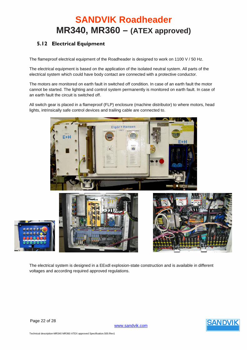
5.12 Electrical Equipment
The flameproof electrical equipment of the Roadheader is designed to work on 1100 V / 50 Hz.
The electrical equipment is based on the application of the isolated neutral system. All parts of the electrical system which could have body contact are connected with a protective conductor.
The motors are monitored on earth fault in switched off condition. In case of an earth fault the motor cannot be started. The lighting and control system permanently is monitored on earth fault. In case of an earth fault the circuit is switched off.
All switch gear is placed in a flameproof (FLP) enclosure (machine distributor) to where motors, head lights, intrinsically safe control devices and trailing cable are connected to.
The electrical system is designed in a EExdl explosion-state construction and is available in different voltages and according required approved regulations.

SANDVIK Roadheader MR340, MR360 – (ATEX approved)
Page 23 of 28
www.sandvik.com
Technical description-MR340 MR360 ATEX approved Specification.500.Rev1
Electric Motors
All electric motors are of 3-phase squirrel cage type and direct-on-line started, requiring a stable power supply.
All motors are protected against overload by means of overload relays. The main motors have also built-in temperature sensors (PTC resistors, thermistors), in order to monitor the temperature of the windings and bearings, against over temperature.
Cutter motor (water cooled) [IP 54] 200 [kW] Hydraulic pump motor (air cooled) [IP 55] 70 [kW] Loader Motor (water cooled) [IP 55] 2 x 36 [kW] Booster pump motor (air cooled) [IP 54] 15 [kW]
SANDVIK Roadheader MR340, MR360 – (ATEX approved)
Page 24 of 28
www.sandvik.com
Technical description-MR340 MR360 ATEX approved Specification.500.Rev1
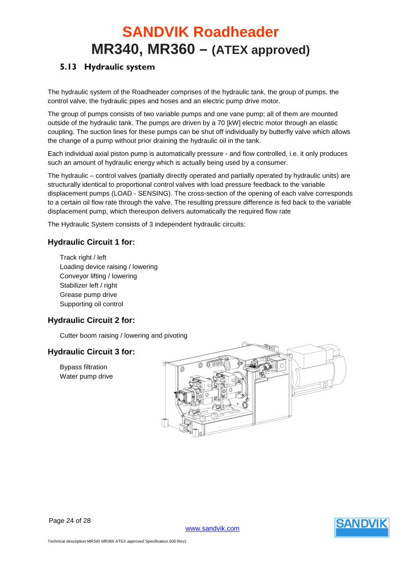
5.13 Hydraulic system
The hydraulic system of the Roadheader comprises of the hydraulic tank, the group of pumps, the control valve, the hydraulic pipes and hoses and an electric pump drive motor.
The group of pumps consists of two variable pumps and one vane pump; all of them are mounted outside of the hydraulic tank. The pumps are driven by a 70 [kW] electric motor through an elastic coupling. The suction lines for these pumps can be shut off individually by butterfly valve which allows the change of a pump without prior draining the hydraulic oil in the tank.
Each individual axial piston pump is automatically pressure - and flow controlled, i.e. it only produces such an amount of hydraulic energy which is actually being used by a consumer.
The hydraulic – control valves (partially directly operated and partially operated by hydraulic units) are structurally identical to proportional control valves with load pressure feedback to the variable displacement pumps (LOAD - SENSING). The cross-section of the opening of each valve corresponds to a certain oil flow rate through the valve. The resulting pressure difference is fed back to the variable displacement pump, which thereupon delivers automatically the required flow rate
The Hydraulic System consists of 3 independent hydraulic circuits:
Hydraulic Circuit 1 for:
Track right / left Loading device raising / lowering Conveyor lifting / lowering Stabilizer left / right Grease pump drive Supporting oil control
Hydraulic Circuit 2 for:
Cutter boom raising / lowering and pivoting
Hydraulic Circuit 3 for:
Bypass filtration Water pump drive

SANDVIK Roadheader MR340, MR360 – (ATEX approved)
Page 25 of 28
www.sandvik.com
Technical description-MR340 MR360 ATEX approved Specification.500.Rev1
5.14 Operators Stand
The operator's stand is located on the left side of the machine. The operator has an optimum view to the cutter head.
Electrical and hydraulic control elements and monitoring systems are mounted in locations visible and easily accessible from the operator's seat. The operator's seat can be moved forwards or back
1 Pedal for safety device 5 Control panel 2 Monitor 6 Hydraulic controls 3 Keyboard for display control 7 Water sequence flow meter 4 Hydraulic controls 8 Hydraulic valves

SANDVIK Roadheader MR340, MR360 – (ATEX approved)
Page 26 of 28
www.sandvik.com
Technical description-MR340 MR360 ATEX approved Specification.500.Rev1
5.15 Cooling and Water Supply System
A convection cooling system is not sufficient for the trouble-free functioning of the machine. The water circuit is to be supplied by the mine water supply. The high pressure unit is to be mounted on the machine.
Therefore, the
• cutter motor (cooling jacket)
• cutter transmission (heat exchanger)
• motors for loader unit (cooling jacket)
• hydraulic fluid (heat exchanger)
have to be water-cooled.
For the ITP-Spraying system a nozzle bar is assembled to the cutter arm / cutter gear of the machine.
The incoming water is filtered before it supplies the cooling circuit. A booster pump station is mounted to step up the return water from the cooling circuit and supply the ITP spraying system

SANDVIK Roadheader MR340, MR360 – (ATEX approved)
Page 27 of 28
www.sandvik.com
Technical description-MR340 MR360 ATEX approved Specification.500.Rev1
Cooling system diagram

SANDVIK Roadheader MR340, MR360 – (ATEX approved)
Page 28 of 28
www.sandvik.com
Technical description-MR340 MR360 ATEX approved Specification.500.Rev1
5.16 Lubrication System
The Roadheader is equipped with one hydraulic driven multi-line lubrication pump, powered from the hydraulic-circuit 1 and mounted on side of the frame.
The multi-line lubrication pumps accommodate pump elements and lubricating points. The delivery volume of each element is infinitely variable within a certain range. Grease is continuously supplied to the connected lubricating points.
Some elements are not lubricated via the central lubrication system but must be manually greased by means of some individual grease nipples and lubrication strips. The lubrication strips act as a central distributor to reach points which are difficult to access or which are located in one of the machine’s danger areas.