Embed Size (px)
Citation preview

World Oil® / JULY 2017 39
A new generation of HPHT sand screens developed
SAND CONTROL
Adopting new technology is a major challenge in a low-cost commodity environment. However, adoption of ceramic sand screens has gained traction as they are considerably more durable than conventional screens and produce notable improvements in well efficiency while reducing costs.
ŝŝ RICHARD JACKSON and SAMUEL JOLY, 3M Company
Sand control is an essential compo-nent of many wells. Each year, operators are forced to expend significant amounts of capital to prevent and repair downhole sand control failures. Additional revenue is lost in reduced production time and less-than-optimal daily rates.
Several downhole sand control tech-nologies have been developed over the years, with stand-alone and gravel pack screens being the most common. Unfor-tunately, these systems have been afflicted by erosion and/or corrosion issues. Hos-tile fluid environments across the pH and salt spectra can corrode, and limit, life expectancy of screen parts, while the con-
stant barrage of hard/abrasive sand parti-cles erodes the screen and widens its slots. This leads to partial or total loss of sand control throughout the hydrocarbon pro-duction cycle. And HPHT environments, typically defined as >150°C and >10,000 psi/bar, exacerbate these problems.
CERAMIC SCREEN DEVELOPMENTThe lack of universal standards for
sand screens made it difficult for science and technology companies to define a suite of globally accepted testing proto-cols to aid technology development. In spite of this situation, a Danish oil and gas company began a collaboration with ESK Ceramics (now 3M Advanced Materials Division) in 2008, to develop a new sand screen material, using technology derived from 3M’s existing technical ceramics platform including:
• Military armor—material is lighter/harder than metals and alloys.
• Mining sector—ceramics’ erosion-resistant characteristics reduce NPT.
• Oil and gas—topside applications. After two years of determining mea-
surement parameters and testing various designs, the first ceramic sand screens, using silicon carbide, were deployed suc-cessfully. To date, ceramic sand screens have been installed in 30+ wells, in various worldwide locations, including produc-ers where conventional sand screens have failed. The screens also have been used suc-cessfully in gas wells with high-rate erosion
velocities (>100ft/sec) in the perforations, and on production sites where a costly de-ployment of gravel pack was avoided.
The ceramic sand screens employ a flexible stack of ceramic rings, Fig. 1. A cus-tomized V-shaped gap between the rings is based on the particle size distribution of the sand at the drilling site. The ring stack is covered with a protective shroud (Fig. 2a), while end caps capture and protect the ceramic stack and anchor the assembly to the base pipe, Fig. 2b. This design encour-ages a natural sand pack formation around
Fig. 1. Ceramic screen ring stack, with gaps of 10 gauge.
Fig. 2a. A protective shroud is placed over a compressed stack of ceramic rings (left). Fig. 2b. Complete sand screen assembly with end caps and anchor (right).
Originally appeared in World Oil® JULY 2017 issue, pg 39-42. Posted with permission.

40 JULY 2017 / WorldOil.com
SAND CONTROL
the ceramic sand screen while reducing the risk of compromised productivity.
Methodology of qualification crite-ria. The biggest challenge to effectively defining sand screen qualification and validation criteria for HPHT environ-ments was defining relevant benchmarks. Engineers also had to design a method to reliably transition from laboratory testing and surface technical qualifica-tion to specifications suitable to meeting downhole HPHT production require-ments. Although some testing qualifica-tions could be derived from ISO 17824 (19s), a more complete qualification methodology had to be developed in partnership with operating companies.
Each operator selected different criti-cal parameters to be tested and qualified, to endorse a technology for field condi-tions. After data analysis, parameters for erosion, robustness, corrosion, burst/collapse, and bending qualifications were agreed upon, which ensured risk-mitigat-ed deployment and placement in hole. This approach required understanding
from both the operators and the screen manufacturer to ensure alignment of ob-jectives, transparency of testing protocol, and a shared understanding of downhole conditions and the required specifica-tions of the product.
Qualification protocol. The follow-ing testing was defined as necessary by operators and the manufacturer, to qual-ify a ceramic screen for general HPHT applications.
Erosion. For sand screens, high-veloc-ity impingement testing entails projecting sand particles at a representative coupon. Testing parameters are listed in Table 1, and were mutually defined by the proj-ect team, based on operator well require-ments. Tests were conducted on ceramic coupons with a 250-µm slot opening. The post-test ceramic coupon was magnified with a SEM, Fig. 3. No deformation, frac-turing of the coupon, or a widening of the slot opening was detectable.
Robustness. Because HPHT gener-ally exhibits deeper and more complex well architectures, and wellheads can be on a platform and subsea, impact tests were performed to ensure that the integri-ty and functionality of the screens would be preserved under normal deployment conditions. Complete HPHT sand screen assemblies were driven into a hard surface to mimic exaggerated sand screen deploy-ment conditions, Fig. 4. After 100 im-pacts, no critical damage occurred.
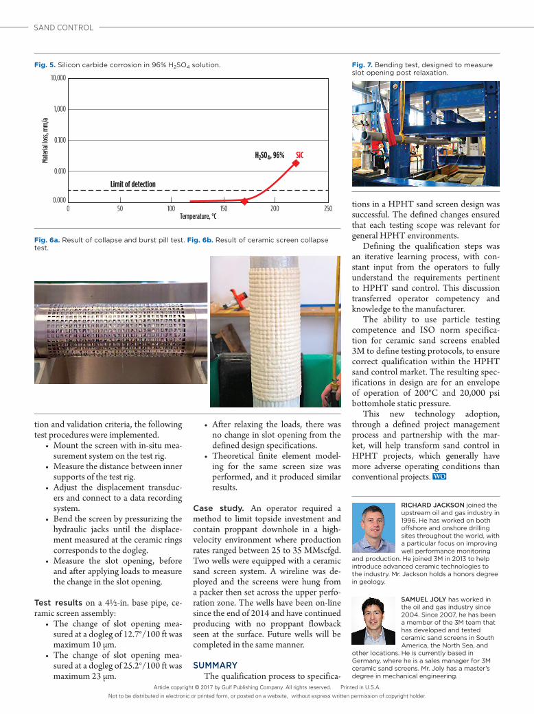
Corrosion. High H2S and CO2 con-centrations and salt-rich environments are common in HPHT wells. The base silicon carbide material was tested in a 96% H2SO4 solution at two temperatures between 150°C and 220°C. Even at the higher temperature, only minimal loss was measured within the limit of detec-tion, Fig. 5. Corrosion also was measured after 28 days in a highly concentrated salt solution. Again, even at high tempera-tures, loss was negligible, Table 2.
Collapse and burst. Aligned to ISO 17824 (API 19s), which covers sand screen collapse and burst testing, ceram-ic sand screens were tested, both at the screen manufacturer’s qualification test-ing facility and at third-party laboratories. The manufacturer developed a plugging pill aligned with the ISO standard, which could withstand a burst pressure of 1,500 psi and differential collapse pressure above 7,500 psi, which was the test rig’s limitation, Fig. 6. These results fulfill the known requirements for HPHT.
Bending. The integrity of ceramic rings and deformation of metal parts were investigated after bending. Figure 7 shows the testing set-up. The aim was for the change in mean slot opening to be less than two gauge (50µm), post-relaxation of the bending forces.
TEST PROCEDURE/RESULTS After establishing an operator/manu-
facturer-derived set of HPHT qualifica-
Table 1. Parameters for a high-velocity impingement test.
Parameter Applied valueFlowrate of liquids 0.2 I/h = 0.0528 gph = 0.0302 bl/dAmount of gas 0.25 Nm3/h = 211.9 scf/dImpact velocity 60 m/s = 197 ft/sSystem pressure CO2 15 bar = 218 psiTemperature 80°C = 176°FTesting duration 72 hAmount of sand 10 g/l = 10,000 ppmParticle size of sand below 150 µmImpact angle 90°
Fig. 3. Post-test SEM images of ceramic coupon (scale bar is 100 µm).
Fig. 4. Surface setup for robustness test.
Table 2. Corrosion rates of silicon carbide in concentrated salt solution.
Temperature, °C Corrosion rate, mm/year130 0.00039160 0.00043190 0.00028220 0.00060
Measurement uncertainty of corrosion rate ± 0.0005 mm/year.
42 JULY 2017 / WorldOil.com
SAND CONTROL
tion and validation criteria, the following test procedures were implemented.
• Mount the screen with in-situ mea-surement system on the test rig.
• Measure the distance between inner supports of the test rig.
• Adjust the displacement transduc-ers and connect to a data recording system.
• Bend the screen by pressurizing the hydraulic jacks until the displace-ment measured at the ceramic rings corresponds to the dogleg.
• Measure the slot opening, before and after applying loads to measure the change in the slot opening.
Test results on a 4½-in. base pipe, ce-ramic screen assembly:
• The change of slot opening mea-sured at a dogleg of 12.7°/100 ft was maximum 10 µm.
• The change of slot opening mea-sured at a dogleg of 25.2°/100 ft was maximum 23 µm.
• After relaxing the loads, there was no change in slot opening from the defined design specifications.
• Theoretical finite element model-ing for the same screen size was performed, and it produced similar results.
Case study. An operator required a method to limit topside investment and contain proppant downhole in a high-velocity environment where production rates ranged between 25 to 35 MMscfgd. Two wells were equipped with a ceramic sand screen system. A wireline was de-ployed and the screens were hung from a packer then set across the upper perfo-ration zone. The wells have been on-line since the end of 2014 and have continued producing with no proppant flowback seen at the surface. Future wells will be completed in the same manner.
SUMMARYThe qualification process to specifica-
tions in a HPHT sand screen design was successful. The defined changes ensured that each testing scope was relevant for general HPHT environments.
Defining the qualification steps was an iterative learning process, with con-stant input from the operators to fully understand the requirements pertinent to HPHT sand control. This discussion transferred operator competency and knowledge to the manufacturer.
The ability to use particle testing competence and ISO norm specifica-tion for ceramic sand screens enabled 3M to define testing protocols, to ensure correct qualification within the HPHT sand control market. The resulting spec-ifications in design are for an envelope of operation of 200°C and 20,000 psi bottomhole static pressure.
This new technology adoption, through a defined project management process and partnership with the mar-ket, will help transform sand control in HPHT projects, which generally have more adverse operating conditions than conventional projects.
RICHARD JACKSON joined the upstream oil and gas industry in 1996. He has worked on both offshore and onshore drilling sites throughout the world, with a particular focus on improving well performance monitoring
and production. He joined 3M in 2013 to help introduce advanced ceramic technologies to the industry. Mr. Jackson holds a honors degree in geology.
SAMUEL JOLY has worked in the oil and gas industry since 2004. Since 2007, he has been a member of the 3M team that has developed and tested ceramic sand screens in South America, the North Sea, and
other locations. He is currently based in Germany, where he is a sales manager for 3M ceramic sand screens. Mr. Joly has a master’s degree in mechanical engineering.
Fig. 6a. Result of collapse and burst pill test. Fig. 6b. Result of ceramic screen collapse test.
Fig. 7. Bending test, designed to measure slot opening post relaxation.
Fig. 5. Silicon carbide corrosion in 96% H2SO4 solution.
0.0000 50 100
Temperature, °C
Limit of detection
H2SO4, 96% SiC
150 200 250
Mate
rial lo
ss, m
m/a
0.010
0.100
1,000
10,000
Article copyright © 2017 by Gulf Publishing Company. All rights reserved. Printed in U.S.A.
Not to be distributed in electronic or printed form, or posted on a website, without express written permission of copyright holder.