Embed Size (px)
Citation preview

San Diego May, 16 2007
PLOPSPanel Line Optimization through Predictive Scheduling

San Diego May, 16 2007
Basic Panel Line Work Flow

San Diego May, 16 2007
Panel Constraints• Drive/ Roller combinations
• Physical restraints

San Diego May, 16 2007
CADThe CAD used in the project has varied. The original attempts were based on AutoCAD versions of DWG and DXF
CAD files. Soon after the first few attempts of CAD formatting, Bender Shipbuilding decided to create multiple CAD files in all possible formats to check the ability of Delmia to import the CAD.

San Diego May, 16 2007
CAD
SSI 05’The project team began the project by looking at SSI 06’ for CAD to be used in the simulation model while overlooking what geometry is currently in SSI 05’. The project team had many delays with receiving CAD from the new version of ShipConstructor software. Bender
Shipbuilding took the initiative to produce useable CAD for the Delmia software.
The first few versions of CAD had all the stiffeners with the panels. The CAD slowly evolved into a Virtual Realty Modeling Language file (VRML). The evolution of the CAD continued, almost devolving into a basic plate shape. The concept to minimize the size and
complexity of the CAD has worked well. The CAD file sizes range from 1 to 88 KB for all the panels used instead of the 2.2MB size files. The information associated with the stiffeners of each panel was entered in to an attribute file.

San Diego May, 16 2007
CAD
SSI 06’ShipConstructor worked on exporting CAD out of the latest version of their software. There was multiple problems with extracting CAD
out of SSI 06’. The process began with creating a bounding box for panels out of the database through the new API. Through brainstorming between group members, many concepts arouse. Pat David, with ShipConstructor USA worked to produce “Delmia object
models” from the API application in ShipConstructor. In the theory, a Visual Basic Program will read the required drawing names and numbers from the build plan and start a part dump of ShipConstructor parts that will be translated into Delmia parts and associated
attribute files. SSI 06’ is the future for this work.

San Diego May, 16 2007
CAD• Center of Gravity (CG)
– The CG of each panel is used to transform the center of the panel from ship coordinates to a local panel coordinate system. If this step is not done, the CAD when loaded into Delmia appears to be nowhere near the Panel Line. The 0,0,0 point of the panel is more important when the panel has to rotated for a “cross-weld” or for preparation of the stiffener fit up area. When a panel rotates in Delmia, the part would rotate about the 0,0,0 point. If the 0,0,0 point of the panel is not in the center of the plate, than the plate will collide with other plates and the building that houses the Panel Line.

San Diego May, 16 2007
CAD• Orientation
– Not only is the location important, the orientation of panels vary through the vessels. Some panels become decks, while others become bulkheads and others become bulwarks. All of the CAD panels need to be aligned or rotated to represent how the panel would actually progress through the Panel Line.

San Diego May, 16 2007
Typical CAD Files

San Diego May, 16 2007
Panel Attributes

San Diego May, 16 2007
Build Plan• Input Data:
– The project used the Primaverre planning software used by Bender .

San Diego May, 16 2007
Model Results

San Diego May, 16 2007
Results

San Diego May, 16 2007
Optimization The team produced logic for the software to load the panels on
to the panel line five different ways.

San Diego May, 16 2007
Optimization
• Option 1:• No optimization. The model loads each panel based on the build
sheet starting from line 1 to the end of the file. However the end user sorts the build sheet will determine the loading sequence.

San Diego May, 16 2007
Optimization • Option 2:
• Before loading, the logic will search for 5 non-rotating panels based on the attribute data. The logic will search one by one through the build sheet (based on the end user sorting method,) each time adding a panel to the search loop. Once 5 non-rotating panels were found, it would fall from the search loop. The logic then scans each panel in the search loop and will skip over the rotating panels to get to the next non-rotating panel in the loop. The logic scans through all the panels in the loop and if none of them can fit on the Panel Line, it simply loads the next panel on the top of the loop regardless if it is a rotating panel or not. Thus, the rotating panels will load only if the 5 non-rotating panels do not have room and if that panel is at the top of the search loop.

San Diego May, 16 2007
Optimization
• Option 3:
• Similar to Option 2. However, if the next panel in the build sheet is a rotating panel, it simply loads the rotating panel and falls out of the optimizing loop.

San Diego May, 16 2007
Optimization
• Option 4:
• Based on Option 2. Thus, the rotating panels are skipped over to find the non-rotating panels to optimize. However, the logic counts how many times the FIRST rotating panel is skipped. If the panel is skipped over more the three times, the logic falls from the loop and simply loads that rotating panel.

San Diego May, 16 2007
Optimization
• Option 5:• This option is similar to Option 4. However, it takes the five
non-rotating panels in the loop and reorders the load sequence based on budgeted hours. The panel with the highest budgeted hours is placed on the top of the list.

San Diego May, 16 2007
Results
San Diego May, 16 2007
Results

San Diego May, 16 2007
Model Results
San Diego May, 16 2007
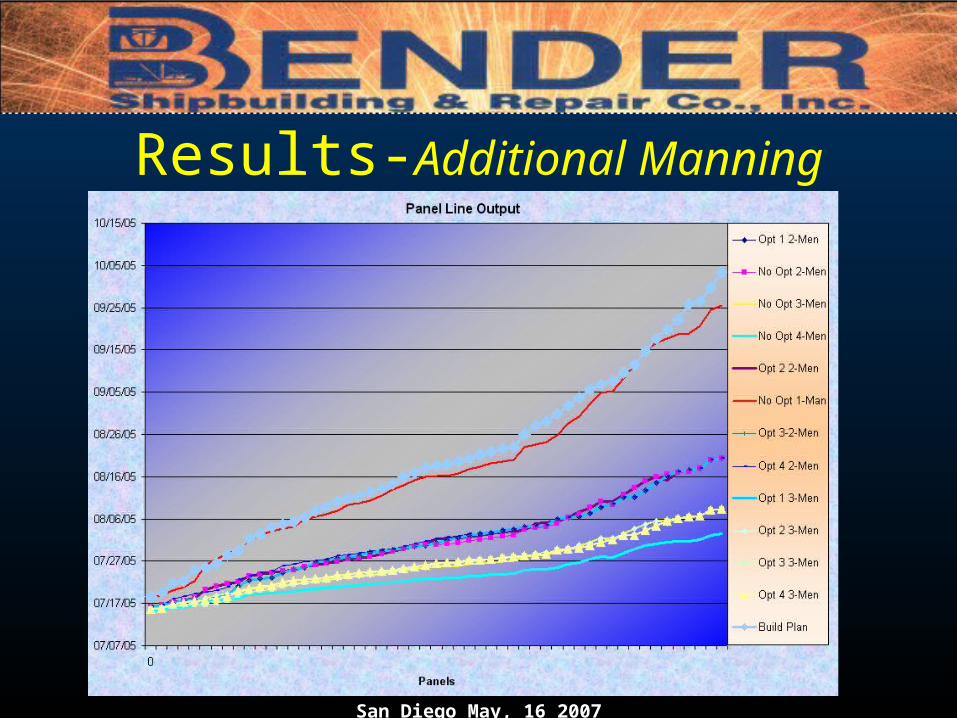
Results-Additional Manning

San Diego May, 16 2007
Final Results• Proposed - A 50% reduction in labor hours is anticipated in the shop floor planning and
scheduling.
• Actual - The project team realized that the tool could load all relevant panel parts and the software could replace the scheduling currently done for the Panel Line by over 80%. The model has shown that it can manipulate the process flow and come up with the same if not better numbers that is currently being done by hand. The team also realized that it would be important to keep a person in the loop, allowing the addition of HOT work.

San Diego May, 16 2007
Final Results - cont • Proposed - Panel throughput should increase 20% by improving the ability to
predicatively schedule and optimize panel production by reducing WIP.
• Actual – Decreasing the process time in the stiffener fit-up area can reduce the WIP by 50%.
The gains shown in process time reduction could be achieved through a multitude of different methods:
• Increased manning
• Improved processes
• Improved jigs and fixtures
• Improved fit-up rates
• Improved tacking rates
• Shifting labor on the Panel Line from positions waiting to work stations fully loaded.

San Diego May, 16 2007
Final Results - cont • Proposed - A 4% reduction in labor hours is anticipated on the manufacturing
shop floor.
• Actual - Reduction in labor hours could be looked at different ways. The process of reducing the processing time of the stiffener fit-up area reduces the overall time it takes to produce the panel from three months to one. While reducing the overall production time by 2/3 the increased cost of manning by only 33%.

San Diego May, 16 2007
Questions