Embed Size (px)
Citation preview

Safe-Drive® Process Refractometer PR-23-SD Generation 1
Best Practices for PR-23-SDwith steam wash system
Version 1.01
Document/Revision No. BP-EN-SDGEN1 1.01 Effective: November 1, 20132
ContentsSection 1 About This Document .......................................................................................................... 3
Section 2 Before Installation ................................................................................................................ 32.1 Installation Location Checklist ....................................................................................... 32.2 Component Checklist ..................................................................................................... 4
Section 3 Safety Requirements ............................................................................................................ 6
Section 4 Installation Process ............................................................................................................. 74.1 Spool piece assembly .................................................................................................... 74.2 Cutting Installation Opening for SDI Valve .................................................................... 84.3 Disassembling SDI Valve for Welding ........................................................................... 94.4 Welding SDI Valve in Place ......................................................................................... 104.5 Reassembling SDI Valve ..............................................................................................114.6 Installing Steam Prism Wash System .......................................................................... 134.7 Inserting and Removing PR-23-SD Sensor ................................................................ 164.8 Inserting Sensor ........................................................................................................... 164.9 Box Flushing ................................................................................................................ 184.10 Removing Sensor ........................................................................................................ 204.11 Removing Wash Nozzle ............................................................................................... 224.12 Inserting Wash Nozzle ................................................................................................. 244.13 Installing DTR Transmitter ........................................................................................... 25
Section 5 Commissioning SD Sensor System ................................................................................. 285.1 Prism Wash Test .......................................................................................................... 295.2 Calibration Check ........................................................................................................ 30
Section 6 Operating and Monitoring SD Sensor System ................................................................ 316.1 Preventive Maintenance Plan (PMP) ........................................................................... 316.2 Check Valve Maintenance ........................................................................................... 326.3 Resetting SD Sensor System ...................................................................................... 32
Section 7 Appendices ......................................................................................................................... 33

© Copyright K-Patents 2013. All rights reserved. 3
Safe-Drive® Process Refractometer PR-23-SD Generation 1 Best Practices
1 About This DocumentThis document is intended for individuals installing, commissioning, operating, and/or servicing the Safe-Drive® Process Refractometer PR-23-SD generation 1 model that has been manufactured in years 2006–2013. The purpose of this document is to provide a quick guide for the abovementioned tasks in the form of K-Patents recommended best practices.
This document in intended for PR-23-SD applications that have a steam wash system (typical application for black liquor).
NOTE: These instructions are for quick reference only. For more thorough guidance, please refer to K-Patents user manual and documentation.
2 Before Installation
2.1 Installation Location ChecklistBefore the SD sensor system is installed, it is important to inspect the installation location carefully for the following conditions:
● Install the SD sensor system onto either vertical or horizontal pipeline. The recommended flow rate is 0.4 m/s – 2 m/s (1.5 ft/s – 6 ft/s).
● Mount the system at waist level. This is the natural and safe height for the system and enables you to use the tools more ergonomically.
● Leave a 1 m (approximately 3 ft) space around the installation for operating around the SD sensor system. For the same reason, the steam connections should be installed on the sides or back of the sensor system.
● Recommended maximum ambient temperature of installation location is 45°C (120°F). ● Avoid locations that are blocked by other piping and/or equipment, or require additional
tools, such as a ladder, to access the sensor. The installation location must be level, firm, and free of clutter to provide safe and easy access to the system.

Document/Revision No. BP-EN-SDGEN1 1.01 Effective: November 1, 20134
● Use suitable type of steam for cleaning the prism. Dry saturated steam and 10-12 bar (150-180 psi) are recommended.
● Access to steam. The distance between the steam supply and the SD sensor system should be considered for the length of steam piping.
● Access to drain for steam trap condensate outlet. ● Emergency shower and eye wash should be easily accessible. Water can also be used
for cleaning SDI valve lip seals and sensor after sensor removal. ● Shut-off valve needs pressurized instrumentation air (5-10 bars / 70-150 psi). ● Ensure connection to the power supply (110-230V AC).
If these conditions do not apply, please reconsider the intended location for your installation or contact K-Patents.
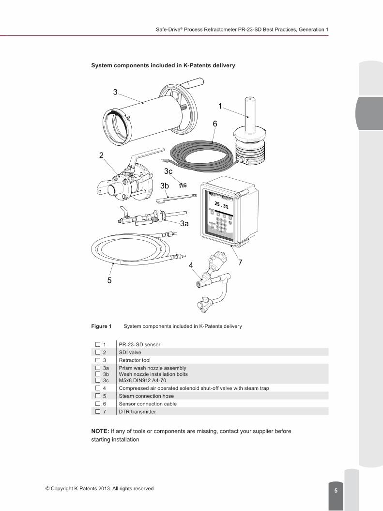
2.2 Component ChecklistBefore starting installation, make sure you have all the tools and components listed below.
NOTE: Components 4 and 5 are connected by union nipple or piping not included in the delivery.
Safe-Drive® Process Refractometer PR-23-SD Best Practices, Generation 1
© Copyright K-Patents 2013. All rights reserved. 5
System components included in K-Patents delivery
Figure 1 System components included in K-Patents delivery
1 PR-23-SD sensor 2 SDI valve 3 Retractor tool 3a 3b 3c
Prism wash nozzle assemblyWash nozzle installation boltsM5x8 DIN912 A4-70
4 Compressed air operated solenoid shut-off valve with steam trap 5 Steam connection hose 6 Sensor connection cable 7 DTR transmitter
NOTE: If any of tools or components are missing, contact your supplier before starting installation

Document/Revision No. BP-EN-SDGEN1 1.01 Effective: November 1, 20136
Installation Equipment
Figure 2 Installation equipment
1 Retractor inner casing Supplied by K-Patents 2 Retractor outer casing Supplied by K-Patents 3 Adjustable wrench 4 Combination wrench, 19 mm / 3/4 in 5 Flat head screwdriver 6 Allen key 8 mm / 5/16 in 7 Thread seal tape 8 Sensor insertion / removal instruction card Supplied by K-Patents 9 Product user manual Supplied by K-Patents
NOTE: The material of the SDI valve body that is welded onto a process pipe is Duplex steel SAF2205 (EN 1.4462, ASTM S32205/S31803). Choose the welding method and filler accordingly.
K-Patents recommends complying with the applicable EN / ASTM standards.
3 Safety RequirementsThese safety requirements must be followed at all times when installing, operating, or servicing PR-23-SD sensor. These are the minimum safety requirements – your company may require additional PPE (personal protective equipment).
For more information on safety issues, please see K-Patents Safety Instructions.
PROCESSREFRACTOMETER
PR-23
1
2
34
56
7
9
8

Safe-Drive® Process Refractometer PR-23-SD Best Practices, Generation 1
© Copyright K-Patents 2013. All rights reserved. 7
Figure 3 Safety symbols
WARNING: Watch out for hot steam and process pipes. Wear protective clothing as instructed below to work safely.
● Only authorized personnel can perform the tasks instructed in this document. ● Long-sleeved safety clothing. ● Safety glasses and/or goggles. ● Hard hat or helmet. ● Protective gloves. ● Locate the nearest emergency shower and eye wash before starting the work. ● Never operate the Safe-Drive® Retractor alone. ● Hard-cap safety boots.
4 Installation ProcessFor more thorough instructions, please refer to K-Patents user documentation or visit the K-Patents website to see the instructional video (www.kpatents.com, PR-23-SD Safe-Drive® Operation Guide Video).
Installation of the SD sensor system consists of ● Cutting pipe opening for SDI isolation valve. ● Welding and assembling the SDI valve onto the processing piping. ● Installing the steam prism wash system. ● Installing the PR-23-SD sensor. ● Installing the DTR transmitter.
4.1 Spool piece assemblyIf the SDI valve was supplied pre-welded and assembled onto a pipe spool piece for integration in existing piping on site, please skip ahead to installing prism wash.

Document/Revision No. BP-EN-SDGEN1 1.01 Effective: November 1, 20138
Figure 4 Vertical and horizontal spool piece assemblies
4.2 Cutting Installation Opening for SDI ValveUse the installation guide sticker provided by K-Patents to determine the installation opening shape and size suitable for your process pipe. If you do not have the guide sticker at hand, please follow the instructions in the images below:
Figure 5 Installation guide sticker
NOTE: For larger pipes, use the same dimensions as for 24” (610 mm) pipes.
To cut the installation opening
1. Cut the installation guide sticker to match the pipe size.2. Clean the surface of the pipe around the installation area and attach the sticker onto
the pipe.

Safe-Drive® Process Refractometer PR-23-SD Best Practices, Generation 1
© Copyright K-Patents 2013. All rights reserved. 9
NOTE: Make sure that the FLOW marker is parallel to the pipe and points to the correct flow direction. On a horizontal pipe the nozzle points downwards and on a vertical pipe it points to right. The SD sensor system must always be installed in horizontal position and on the side of the pipe.
3. Drill two holes – 50 mm (2”) and 25 mm (1”) – as guided by the sticker.4. Remove the bridge between the holes so that the opening is exactly the shape of
the sticker.
WeldCutout
Safe Drive mounting flange
Process pipe
Weld
Cutout
Safe Drive mounting flange
Process pipe
Figure 6 Installation on vertical and horizontal pipes
4.3 Disassembling SDI Valve for WeldingTo avoid thermal damage to the isolation valve sealing, you must separate the valve body from the valve assembly before it is welded onto the pipe.

Document/Revision No. BP-EN-SDGEN1 1.01 Effective: November 1, 201310
NOTE: Be very careful not to drop or lose any parts that come loose when separating the body from the assembly.
To disassemble the SDI valve, open the four (4) M10 allen key bolts with an 8 mm (5/16”) allen key (1).
Figure 7 Disassembling valve
4.4 Welding SDI Valve in PlaceAfter you have disassembled the SDI valve, the valve body is welded onto the process pipe.
● The material of the SDI valve body is Duplex steel SAF2205 (EN 1.4462, ASTM S32205/S31803). Choose the welding method and filler accordingly.
● See the attached drawings 2149 (MTG) and MTG472 for more detailed welding instructions.
● Follow all local requirements for welding. ● K-Patents recommends complying with the applicable EN / ASTM standards. ● Consider the materials and shapes of the welded objects when performing welding
pre-processing (tools, cleaning, preheating). ● Consider the materials and shapes of the welded objects when performing welding
post-processing (postheating, fluxing).
1

Safe-Drive® Process Refractometer PR-23-SD Best Practices, Generation 1
© Copyright K-Patents 2013. All rights reserved. 11
Figure 8 Welding on vertical and horizontal pipes
4.5 Reassembling SDI ValveAfter the SDI valve body has been welded in place, reassemble the valve in reverse order.
NOTE: Make sure that the seals of the ball valve are propely aligned.
Valve handle always positioned at top
Widest bayonet lug always positioned at top
90°
Weld
Processpipe
90°
Weld
Processpipe
NOTE!The material of the welded parts is Duplex steel SAF2205

Document/Revision No. BP-EN-SDGEN1 1.01 Effective: November 1, 201312
Valve handle always positioned at top
Widest bayonet lug always positioned at top
Figure 9 Reassembling valve on vertical and horizontal pipes
● Make sure that the SDI valve handle and the largest bayonet connection are on top. Otherwise, you will not be able to insert the sensor in its place.
● Tighten the bolts to a torque of 36 N-m (26 lb-ft) with an 8 mm (5/16”) allen key.
WARNING: Always shut the main steam valve before performing any work on the wash nozzle.
To reinstall the wash nozzle assembly1. Insert the wash nozzle
assembly to its place (1)..
1

Safe-Drive® Process Refractometer PR-23-SD Best Practices, Generation 1
© Copyright K-Patents 2013. All rights reserved. 13
<
2. Tighten the large nozzle nut (1).
NOTE: Make sure the valve orientation is correct.3. Attach the safety cover
over the nozzle nut (2).4. Tighten the safety cover
M5 Allen screw (3).5. Attach the nozzle guide
plate (4).6. Tighten the guide plate
with two (2) M5x10 screws to the welding body (5).
7. Tighten the M5x8 screw to nozzle (6)..
8. Attach the steam line (1).9. Open the steam
connection (2).
4.6 Installing Steam Prism Wash SystemIn black liquor service material deposit, scaling or coating may occur on the prism surface. To avoid this, you need to install an integral prism wash with steam that uses the retractable nozzle included in the SDI valve.
Important Steam Prism Wash Considerations ● The distance from the steam nozzle on the SDI valve to the steam shut-off valve
should be kept as short as possible to avoid condensate. The recommended length of the distance is 0.6 m (2 ft) or less.
● Separate or isolate the power to the solenoid from the power to the transmitter by installing a safety switch. This enables the steam wash to be serviced without having to power down the whole SD sensor system.
● Pipe the steam trap properly to drain so that the trap is not blowing hot steam. ● Steam piping upstream of shut-off valve is ½” or larger.
3
56
4
2
1
2
1
OPEN

Document/Revision No. BP-EN-SDGEN1 1.01 Effective: November 1, 201314
● In addition to the SDI valve steam fittings, the following components must be included in the steam wash installation:
● steam shut-off valve ● air-operated solenoid valve ● steam trap ● switch or terminal for power isolation
For K-Patents recommendations, please see K-Patents Steam Instructions. ● OPTIONAL, in case of contaminants: To remove any contaminants within the
steam source, installing a steam strainer is recommended. See K-Patents list of recommended accessories.
● OPTIONAL, in case of excessive pressure: If the steam pressure exceeds to maximum pressure differential, a pressure reducing valve (PRV) needs to be installed to reduce the steam pressure to optimal design. See K-Patents list of recommended accessories.
Figure 10 Mounting steam wash system
For more detailed information on steam-realted issues, please see K-Patents Steam Instructions.
To install the wash system
1. Define the wash setting values for the wash system: ● steam source minimum and maximum pressures ● wash time – the time one wash will last (seconds) ● recovery time – the time after the wash has finished, before the measurement is
live data again (seconds) ● interval – the time between washes (minutes)

Safe-Drive® Process Refractometer PR-23-SD Best Practices, Generation 1
© Copyright K-Patents 2013. All rights reserved. 15
Recommended steam prism wash settings
Minimum above process pressure
Maximum above process pressure Wash time Recovery Interval
Steam (SN) 5 bar (75 psi) 8 bar (115 psi) 3-5 s 20-30 s 20-30 min
NOTE: Damage caused to prism by excessive pressure or washing is not covered by the product warranty.
Choose the correct steam source pressure by comparing it to the process pressure.The steam source pressure must be higher than process pressure to provide adequate washing, but excessive pressure may also cause premature damage or etching of the prism. Also, if the washing phase is programmed to last too long, the prism may wear out prematurely.
2. Install the steam pipes in the SDI valve, as instructed below.NOTE: All the necessary wash fittings are included in the valve.
3. Connect the steam wash system power supply.
For more information, please see K-Patents Steam Instructions.
Figure 11 Wiring steam wash system
For more information on controlling the prism wash cycle, please refer to chapter Configuring relays in K-Patents user documentation.

Document/Revision No. BP-EN-SDGEN1 1.01 Effective: November 1, 201316
4.7 Inserting and Removing PR-23-SD SensorWARNING: Always use the Safe-Drive® Retractor tool for inserting and removing the sensor. Removing the sensor without the Retractor tool may cause a life-threatening situation, if there is any pressure in the process pipe. Inserting or removing sensor without Retractor tool may also cause damage to the lip seal. Always store the Retractor tool indoors in a clean and dry location.
Successful sensor insertion and removal can only be guaranteed when the Retractor tool is used and the instructions for insertion or removal are carefully followed.
NOTE: Check the Retractor tool visually before starting insertiong / removal process. Make sure the handwheel rotates freely.
WARNING: If you detect leaking at any point of sensor insertiong or removal process, revert immediately to the previous step in the process. Do not continue insertion / removal until the reason for leakage has been cleared and fixed.
Insert and remove the sensor as instructed in the following chapters. For more thorough instructions, please refer to K-Patents user documentation or visit the K-Patents website to see the instructional video on inserting and removing the sensor (www.kpatents.com, PR-23-SD Safe-Drive® Operation Guide Video).
4.8 Inserting SensorBefore you start
● check that the gaskets and gasket surfaces are clean and undamaged
● remove the sensor cable gland and unlock Inner casing
1. Insert the sensor to Inner casing so that the inner casing latch is slightly to the left of top and sensor cable passage is straight down.
2. When sensor flange is flush with the bottom of Inner casing, turn Inner casing 1/6 turn clockwise to lock it to the flange.
3. Push down the locking latch.
Put the Safe-Drive® Retractor with sensor onto a table or similar surface so that the hand wheel has space to turn.
1. Fit Outer casing over Inner casing so that the groove on Inner casing matches the dot on Outer casing.
2. Turn the hand-wheel clockwise until it stops to draw the sensor into the Retractor.
1
23
1
1
22

Safe-Drive® Process Refractometer PR-23-SD Best Practices, Generation 1
© Copyright K-Patents 2013. All rights reserved. 17
Lift the Retractor (with sensor) handle up over the isolation valve flange.
1. Turn the Retractor a 1/6 turn to the right to lock the bayonet.
2. Push down the latch on Outer casing.
1. Close the blow-out ball valve underneath the isolation valve,
2. Lift up the isolation valve handle locking plate.3. Open the isolation valve by turning the valve handle a
quarter turn to the right.
Turn the hand-wheel counterclockwise until it stops.
WARNING: If you detect leaking, revert immediately to the previous step. Do not continue insertion until the reason for leakage has been cleared and fixed.
Fit the four M12 nuts to the bolts holding the sensor to the isolation valve and screw them on with a 19 mm or 3/4” wrench.
NOTE: Set the torque at 50 Nm.
1. Turn the wheel a quarter turn to the right.2. Unlock the latch of the outer casing.3. Turn the casing to the left until the handle is up on top.
LIFT POINTS
3
12
4
1
23
5
140 mm(5.5")6
4 x M1250Nm (37ft/lbs)
7
2
3 1
8
90°
AB

Document/Revision No. BP-EN-SDGEN1 1.01 Effective: November 1, 201318
1. Turn the hand-wheel to the left to drop the thread.2. Lift off Outer casing.
1. Lift up the latch of the inner casing to unlock.2. Turn the casing a 1/6 turn to the left to release it from
the flange.
Lift Inner casing away from the sensor head.
1. Take off sensor nameplate and the gasket underneath.2. Put interconnecting cable through the cable gland.3. Connect the interconnecting cable to the sensor.4. Screw the cable gland to the sensor.5. Fit the gasket and nameplate onto the sensor and screw
the nameplate back on.
Turn on transmitter power to power up the SD sensor system.
4.9 Box FlushingCarry out box flushing before sensor removal when the sensor has been in process for several months. Box flushing removes dried process medium from isolation valve and makes sensor removal easier.
WARNING: Do not activate box steam flush, if the sensor and the Retractor tool are not installed to the isolation valve!
1
2
9
1
2
10
11
2
4
3
12
1 & 5

Safe-Drive® Process Refractometer PR-23-SD Best Practices, Generation 1
© Copyright K-Patents 2013. All rights reserved. 19
1. Close the 1/4” valve to the nozzle (1).
2. Open the 1/4” valve to the box (2).
3. In the DTR transmitter, go to MENU › SENSOR STATUS and activate wash by pressing WASH button.
Repeat the wash 3–5 times.
4. Close the 1/4” valve to the box (4).
5. Open the 1/4” valve to the nozzle (5).
12
OPEN
CLOSE
54OPEN
CLOSE

Document/Revision No. BP-EN-SDGEN1 1.01 Effective: November 1, 201320
4.10 Removing SensorSwitch off the DTR to cut off power from the sensor.
1. Remove the sensor nameplate and the gasket underneath.2. Screw off the cable gland.3. Disconnect the interconnecting cable4. Remove the cable from sensor5. Place gasket and nameplate on the sensor head and screw
the sensor nameplate back on.
NOTE: If another inline sensor is connected to the same DTR, disconnect the loose cable from the DTR and turn power on again.
1. Unlock the latch on Inner casing.2. Lift Inner casing over the sensor head. Connect the casing
to the sensor flange bayonet.
1. Turn the casing a 1/6 turn to the right to lock it onto the flange.
2. Lock the inner casing latch.
1. Grab Outer casing with one hand on the handle and the other hand on the wheel. Fit Outer casing over Inner casing and all the way to the isolation valve bayonet keeping the handle upwards.
2. Rotate the hand wheel clockwise to get thread of the inner casing running through the wheel.
1. Turn Outer casing a 1/6 turn to the right to lock it onto the isolation valve.
2. Push down the outer casing latch.
21 & 5
3
1
4
2
2
1
12
3
60°
1
24
1
2
5

Safe-Drive® Process Refractometer PR-23-SD Best Practices, Generation 1
© Copyright K-Patents 2013. All rights reserved. 21
Open and remove the four M12 nuts on the bolts holding the sensor to the isolation valve using a 19 mm or 3/4” wrench.
Turn the hand wheel clockwise until it stops to remove the sensor from process.
WARNING: If you detect leaking, revert immediately to the previous step. Do not continue removal until the reason for leakage has been cleared and fixed.
1. Lift up the isolation valve handle locking plate.2. Close the isolation valve on by turning the handle a quarter
turn to the left.
IMPORTANT: The isolation valve is properly closedwhen the handle points away from the sensor and thelocking plate drops down over the handle.
3. Open the blow-out valve under the isolation valve.
Some process liquid should leak from the valve. If there is none, the valve may be defective.
WARNING: Watch out for splashing!
4. Carry out box flushing to get rid of any process liquid inside the isolation valve. See chapter 4.9 Box Flushing for instructions.
1. Lift the outer casing locking latch.2. Turn Outer casing a 1/6 turn to the left so that the handle
comes up on top.
4 x M12
6
1
140 mm(5.5")
7
12
8
3
12
9

Document/Revision No. BP-EN-SDGEN1 1.01 Effective: November 1, 201322
Take a good grip on the hand wheel and the handle and pull out the Safe-Drive® Retractor with the sensor inside.
A firm hold of the tool is essential as the combination of the tool and the sensor is noticeably heavier than Retractor alone.
NOTE: To ensure the isolation valve after the Safe-Drive tool with the sensor have been removed, you can bolt a standard ANSI 1.5” 105 lbs blind flange to it with 1/2” (M12) bolts and nuts.
WARNING: The sensor tip is hot and may be covered with liquor. It is recommended to rinse the sensor tip and the isolation valve with hot water.
Put the Safe-Drive® Retractor with sensor onto a table or similar surface so that the hand wheel has space to turn.
1. Turn the wheel counterclockwise until the trapezoidal thread is all the way inside the outer casing and loose from the wheel.
2. Pull the outer casing off.
1. Open the latch on the inner casing.2. Keep sensor steady with one hand and turn Inner casing
counterclockwise with the other hand to unlock Inner casing from sensor.
3. Pull off the sensor.
4.11 Removing Wash NozzleRemove the wash nozzle as instructed in the following illustrations: For more thorough instructions, please refer to K-Patents user documentation or visit the K-Patents website to see the instructional video on inserting and removing the sensor (www.kpatents.com, PR-23-SD Safe-Drive® Operation Guide Video).
WARNING: Always shut the main steam valve before performing any work on the wash nozzle.
10
LIFT POINTS
1
2
11
12
3
12

Safe-Drive® Process Refractometer PR-23-SD Best Practices, Generation 1
© Copyright K-Patents 2013. All rights reserved. 23
1. Close the steam supply.2. Close the 1/4” ball valve
(1).3. Remove the incoming
steam pipe from the 1/4” ball valve (2).
NOTE: Do not remove the check valve!
4. Remove the nozzle guide (3).
5. Loosen the nozzle nut 1/4 turn at time with a 22 mm / 7/8 in wrench until you can pull the nozzle about 150 mm / 6 in outwards (1).
IMPORTANT: Do not open the nozzle nut for more than 2 turns.
6. Close the 3/8” ball valve (2).
7. Loosen the nozzle nut entirely (3).
NOTE: Only little process liquid should flow from the nozzle. If process liquid keeps on flowing, the nozzle isolation valve is damaged and it is not safe to remove the nozzle. Do not proceed with nozzle removal.
8. Pull the nozzle out of the isolation valve (4).
WARNING: The nozzle tip is hot and may be covered with liquor. It is recommended to rinse the nozzle tip and the isolation valve with hot water.
2 3
1
2
3
4
1
CLOSELOCK

Document/Revision No. BP-EN-SDGEN1 1.01 Effective: November 1, 201324
4.12 Inserting Wash NozzleInsert the wash nozzle as instructed in the following illustrations: For more thorough instructions, please refer to K-Patents user documentation or visit the K-Patents website to see the instructional video on inserting and removing the sensor (www.kpatents.com, PR-23-SD Safe-Drive® Operation Guide Video).
WARNING: Always shut the main steam valve before performing any work on the wash nozzle.
Check the nozzle and valve before inserting the wash nozzle. Use teflon tape for all thread connections.
1. Fasten the nozzle to the 3/8” isolation valve (1).
2. Tighten the nozzle nut (2).
3. Carefully open the 3/8” nozzle isolation valve (3).
NOTE: If process liquid is leaking severely, close the isolation valve immediately and do not proceed with nozzle insertion.
4. Push nozzle into the process pipe (4).
5. Fasten the nozzle guide (5).
6. Tighten up nozzle nut (2).
<
7. Attach steam pipe to 1/4” ball valve (1).
8. Open the 1/4” ball valve (2).
9. Open the steam supply.
2
3
4
5
1
OPEN LOCK
1
2

Safe-Drive® Process Refractometer PR-23-SD Best Practices, Generation 1
© Copyright K-Patents 2013. All rights reserved. 25
4.13 Installing DTR TransmitterThe indicating transmitter DTR is a specialized computer designed to process data received from one or two sensors. The transmitter consists of a protecting enclosure, a front panel, an LCD display and a keyboard. Knockout padlock provisions are included for locks to prevent unauthorized access.
Figure 12 DTR transmitter
● DTR transmitter location: ● easily accessible ● well lit, but no direct sunlight ● dry ● ambient temperature range of the transmitter is 0–45 °C (32–113 °F) ● free of vibration or other such disturbances
● Consider the interconnecting cable length when choosing the installation location. The standard delivery is 10 meter (33 feet) of cable and the maximum allowed length is 200 meters (660 feet). You can use your own cable as long as it meets IEC 61158-2 type A standard requirements. For more information, please refer to chapter Interconnecting cable specifications in K-Patents user documentation.
● Consider installing a drip shield to protect the transmitter from rain, sun and dust, especially if the transmitter is installed outside.
WARNING: The transmitter does not have a built-in power switch so it is always powered when connected to a power source. K-Patents recommends mounting an external power switch to control the power supply.
To install the transmitter1. Install the transmitter vertically on an upright surface (wall) using the four mounting feet,
preferably on the eye level of the user.WARNING: Do not drill mounting holes in the enclosure. That will affect the protection class of the enclosure and damage the electronics.
2. Connect the PR-23-SD sensor: ● Remove the four (4) screws holding the sensor nameplate. ● Connect the signal wires to terminals 1 and 2.

Document/Revision No. BP-EN-SDGEN1 1.01 Effective: November 1, 201326
● Connect the cable shield to terminal 3. ● Tighten up the cable gland. ● Screw the nameplate back on.
NOTE: To avoid damage from stray voltages and short-circuiting, always disconnect the sensor cables from the transmitter before removing the sensor.
Figure 13 Sensor electrical connections
3. Open the front panel by loosening the front panel screw.WARNING: Always check that the power is off before opening the front panel. If the green power indicator light is on, there is still power in the system. To completely turn off the power, unplug the power supply cord or use the external power switch (if installed).
Figure 14 Opening transmitter front panel

Safe-Drive® Process Refractometer PR-23-SD Best Practices, Generation 1
© Copyright K-Patents 2013. All rights reserved. 27
4. Connect the primary AC power to a separate terminal strip in the lower right-hand corner of the motherboard. The three terminals are marked 31/L, 32/N, and 33/PE (protective earth), which is directly connected to the exposed metal parts if the transmitter.
5. Connect the wiring wash relay to solenoid valve from the RELAYS terminals.6. Connect the 4-20mA output.
Figure 15 Transmitter H1 and motherboard connections
H1A 1 2 3 Connection for Sensor A, signal wires (1, 2), cable shield (3).B 1 2 3 Connection for Sensor B, signal wires (1, 2), cable shield (3).
Motherboard
11 12 4–20 mA output 1, positive (11), negative (12), max. load 1000 Ohm, galvanically isolated.
13 14 4–20 mA output 2, positive (13), negative (14), max. load 1000 Ohm, galvanically isolated.
21 22 Relay 1, one contact output, max. 250 V AC, max. 3 A.23 24 Relay 2, one contact output, max. 250 V AC, max. 3 A.
31 32 33 Power, L (31), N (32), protective earth (33), 100-240 V AC, 50–60 Hz. An external power switch is recommended.
41 4224V terminal for DTR internal use only.NOTE: Connecting terminal to external 24V supply will void warranty. Connecting external devices to 24V terminal will void warranty.
51 52 53 54 55
Switch inputs: switch 1 (51), switch 2 (52), switch 3 (53), switch 4 (54) and common (55). A voltage of 3 V DC is provided over each switch.The switch terminals are galvanically isolated.

Document/Revision No. BP-EN-SDGEN1 1.01 Effective: November 1, 201328
7. OPTIONAL: Setting up an Ethernet connection. Data can be downloaded from the transmitter to a computer via an Ethernet connection. The Ethernet connector can be found on the underside of the front panel.
Figure 16 Ethernet connection location
For more information on Ethernet connection, please refer to chapter Ethernet connection specification in K-Patents user documentation.
5 Commissioning SD Sensor SystemAfter installing the SDI valve, PR-23-SD sensor, and DTR transmitter, go through the following check list to make sure the SD sensor system is functioning correctly.
For more thorough instructions, please refer to K-Patents user documentation or visit theK-Patents website to see the instructional video (www.kpatents.com, PR-23-SD Safe-Drive® Operation Guide Video).
Commissioning checklistSafe-Drive start-up
Task OK Failed Menu path NotesCheck that the wiring has been done according to the attached wiring diagram.Connect the power.Check that the status isNORMAL OPERATION (if there is a sample)NO SAMPLE (if the process pipe is empty)Check process temperatures.Check the serial number.Check that the parameters are set according to the delivery data sheet (DDS).
CALIBRATION › CHEMICAL & FIELD PARAMETERS

Safe-Drive® Process Refractometer PR-23-SD Best Practices, Generation 1
© Copyright K-Patents 2013. All rights reserved. 29
Configure the mA output. CALIBRATION › OUTPUTS › mA OUTPUTS
For more information, see chapter Configuring mA Outputs in K-Patents PR-23 Instruction Manual.
Configure prism wash relay (relay 1 or 2).
CALIBRATION › RELAYS
For more information, see chapter Configuring relays in K-Patents PR-23 Instruction Manual.
Prism wash test
Task OK Failed NotesObserve the temperature and optical image for slight changes that indicate that wash is functioning. One or more of the following changes should take place:- nD value decreasing (most apparent change)- T value decreasing- QF value decreasing or increasing
For more information, see chapter 5.1 Prism Wash Test in these instructions and chapter Prism wash in K-Patents PR-23 Instruction Manual.
Calibration check
Task OK Failed NotesCheck that calibration corresponds to the lab results
CALIBRATION › CHEMICAL & FIELD PARAMETERS › FIELD PARAMETERS
For more information, see chapter 5.2 Calibration Check in these instructions and chapter Calibrating the concentration measurement in K-Patents PR-23 Instruction Manual.
5.1 Prism Wash TestPrism wash system is essential for a fully functional refractometer. Regular testing of the prism wash is highly recommended.
The curve should react to the wash and the temperature change slightly.
NOTE: Your transmitter may not look excatly like the image above during the wash. The visible changes in the curve and the temperature depend on viscosity, steam pressure and temperatures of solids and steam and also to your version of the software.

Document/Revision No. BP-EN-SDGEN1 1.01 Effective: November 1, 201330
Figure 17 Changes in concentrations during succesful prism wash
5.2 Calibration CheckExtract 3-5 samples in a couple of days’ time. Results from these samples can be used as a reference for calibration.
In case there are deviations from the lab results, check that washes are functioning correctly (see Prism wash test in the commissioning checklist).When comparing lab results if there is a consistent offset, perform a BIAS adjustment from CALIBRATION menu. For more information, see chapter Calibrating the concentration measurement in K-Patents PR-23 Instruction Manual.
Figure 18 BIAS

Safe-Drive® Process Refractometer PR-23-SD Best Practices, Generation 1
© Copyright K-Patents 2013. All rights reserved. 31
If there is a need for frequent calibration, make sure that wash is functional and remove the sensor to check visually that the prism is clean and has not been damaged. Re-install the sensor and run complete field calibration (see chapter Entering field calibration parameters in K-Patents PR-23 Instruction Manual). After this, contact your local supplier.
6 Operating and Monitoring SD Sensor SystemThe SD sensor system runs automatically and does not need to be separately operated. If there are no alarming changes in the diagnostic values or no alarm messages, you do not need to adjust the operation. The main task of the operator is to make sure that the washes and steam connections are functioning as they should.
To rehearse the use of DTR transmitter, please visit demo.kpatents.net.
K-Patents recommends that all new users participate in K-Patents training before using the product.
6.1 Preventive Maintenance Plan (PMP)Preventive Maintenance Plan (PMP) should be adopted in order to prevent bigger maintenance procedures. Here are the recommended tasks:
Task Weekly Annual NotesCheck the functionality of diagnostics: X See the attached PMI checklist.
CONC (measurement value of output)
This value should be closely monitored daily for a week to set the default reading for weekly inspections
CALC (chemical curve of calibration)
This is the default reading from the chemical curve concentration reading set in calibration, to which you can compare the CONC values to.
TEMP (temperature)Process temperature.
QF (quality factor) Typically 30-100. If QF drops 20 units below the normal level, perform a prism wash test (see Commissioning checklist).
LED (exposure time) Typically <30. If the LED value increases significantly, perform a prism wash test (see Commissioning checklist).
HD HUM (internal humidity% of sensor)
If HUM HD rises above 50%, the system issues an alarm to replace the desiccant. For more information, see K-Patents PR-23 Instruction Manual.
Check the functionality of wash system. X See Prism wash test in Commissioning
checklist.Check the steam pressure. X Typically 5-6 bar (75-90 psi) over process
pressure.Remove the sensor and check the prism visually for dirt and wear. X
If the prism looks worn, run an nD verification and replace the prism, if needed. For more information on nD verification, see K-Patents PR-23 Instruction Manual
Inspect the check valve: clean the small holes and see that the valve sealing is intact.
XReplace the check valve every 2 years. For more information, see chapter 6.3 Check Valve Maintenance.

Document/Revision No. BP-EN-SDGEN1 1.01 Effective: November 1, 201332
Clean the filter in the steam connection line. X
Verify calibration. Do this as often as your own quality system and local requirements demand.
Please use the attached Preventive Maintenance Inspection (PMI) Checklist for recording the weekly preventive maintenance tasks.
6.2 Check Valve MaintenanceCheck valve is one of the few moving parts in the wash system. Checking the valve sealing and cleaning the small holes in case of dirt particles annually is essential.
Figure 19 Taking check valve apart for maintenance
6.3 Resetting SD Sensor SystemIf the SD sensor system needs to be reset, you can either
● Switch the power off and back on again, ● Restart the sensor through transmitter from MENU › SENSOR STATUS › SLOPE ›
SENSOR RESTART or ● Press the reset button, as instructed below.
1. Open the DTR transmitter front panel.2. Press the reset button on the inside of the front panel using a thin stick or a similar tool.
The display will black out for a few seconds. The SD sensor system will be back up in operation within 30 seconds.
Figure 20 Reset button

Safe-Drive® Process Refractometer PR-23-SD Best Practices, Generation 1
© Copyright K-Patents 2013. All rights reserved. 33
7 Appendices
Preventive Maintenance Inspection Weekly Checklist
Inspection report

Preventive Maintenance Inspection
Weekly ChecklistDate CONC CALC TEMP QF LED HD
HUMSteam Wash
Y/NChecked by

Safe-Drive® Process Refractometer PR-23-SD Best Practices, Generation 1
© Copyright K-Patents 2013. All rights reserved. 35

Document/Revision No. BP-EN-SDGEN1 1.01 Effective: November 1, 201336

Safe-Drive® Process Refractometer PR-23-SD Best Practices, Generation 1
© Copyright K-Patents 2013. All rights reserved. 37

K-Patents OyP.O. Box 77FI-01511 Vantaa, FinlandTel: +358 207 291 570Fax: +358 207 291 577Email: [email protected]
K-Patents, Inc.1804 Centre Point Circle, Suite 106Naperville, IL 60563, USATel: (630) 955 1545Fax: (630) 955 1585Email: [email protected]
K-Patents (Shanghai) Co., Ltd17-05H, 17F, Times Square No. 500Zhyang Yang RoadPudong District, Shanghai, ChinaTel: +86 21 5178 2775Fax: +86 21 5178 2799
www.kpatents.com