Embed Size (px)
Citation preview

CBE2027 Structural Analysis I Chapter 3 – Analysis of Determinate Plane Frames
HD in Civil Engineering Page 3-1
PLANE FRAMES
A frame is a structure composed of straight-line members. The members
may be connected by rigid joints, pin-connected joints and semi-rigid joints.
If all the joints are pins (which transmit no bending moments), the frame is
commonly called a truss. Rigid joints are capable of transmitting both
forces and bending moments.
A rigid frame is one in which some or all of its joints are rigid. Rigid frames
are usually statically indeterminate. Our study will be confined to
determinate plane frames. In a plane frame, all the members and loading
must be in the same plane.
A frame is completely analyzed when its support reactions, and the
variations in axial forces, shear forces and bending moments along all its
members are found.
Rigid Frame
Frame with an
internal hinge
Truss (Pin-jointed Frame)

CBE2027 Structural Analysis I Chapter 3 – Analysis of Determinate Plane Frames
HD in Civil Engineering Page 3-2
Rigid Joints
At rigid joints, the ends of connected members must not only move together
vertically and horizontally but must all rotate by the same amount. A rigid
joint preserves the angle between members connected to it.
In steel structures, rigid and pin-joints consist of welded connections and
simple bolted connections respectively. There is another type of connection
in between of these two extremes and it is called a semi-rigid connection
(the connection is neither rigid nor pinned, it is in between these two
extremes). In reinforced concrete structures, beams and columns are
usually formed together resulting in substantially rigid joints.
A
B C
D
L
H P.I.
P.I.
P.I.
B' C'

CBE2027 Structural Analysis I Chapter 3 – Analysis of Determinate Plane Frames
HD in Civil Engineering Page 3-3
PROCEDURES FOR THE ANALYSIS OF DETERMINATE PLANE
FRAMES
1. Find the support reactions. (By using the equations of equilibrium
and the equations of condition if any).
2. Find the member end forces.
(a) Take each member and joint as free-body, find the axial force,
shear force and bending moment at the ends of the member
and joint.
(b) Each free-body diagram must show all external loads, support
reactions and possible internal forces acting on the member
and joint.
(c) A rigid joint can transmit two force components (V & N) and
a moment.
At a hinge, the internal moment is zero.
3. Plot the axial force, shear force and bending moment diagrams on an
outline of the frame.
(a) A common convention is to draw the bending moment
diagram on the tension side of the frame. (For reinforced
concrete frames, designers often draw the bending moment
diagram on the tension side. This allows the designer to tell at
a glance on which side of the frame steel reinforcement
should be placed.)
(b) The axial force diagram may be plotted on either side of the
member, with proper indication for tension and compression.
(Tension --- +ve, compression --- -ve)
(c) The shear force diagram may be plotted on either side of the
member but normally follows the convention used for the
bending moment diagram. (i.e. follows the convention of
plotting shear force and bending moment of beam). This can
be done by treating each individual member as a beam
element, plot the shear force diagram from the left end to the
right end of the member and draw the bending moments on
the tension side of the member.

CBE2027 Structural Analysis I Chapter 3 – Analysis of Determinate Plane Frames
HD in Civil Engineering Page 3-4
Example 1
Determine the support reactions, and draw the axial force, shear force and
bending moment diagrams for the frame. Joint B is a rigid joint.
A
BC
4m
6m
10 kN
2 kN

CBE2027 Structural Analysis I Chapter 3 – Analysis of Determinate Plane Frames
HD in Civil Engineering Page 3-5
Solution:
HA VA
MA
A
BC
4m
6m
10 kN
2 kN
∑X = 0, HA = 2 kN
∑Y = 0, VA = 10 kN
Take moment about A,
MA = 10*4 + 2*6 = 52 kNm

CBE2027 Structural Analysis I Chapter 3 – Analysis of Determinate Plane Frames
HD in Civil Engineering Page 3-6
Free-body diagrams for the members and joint, and their member end
forces.
B
C
10 kN
B
B
A
10 kN
52 kNm
10
40
10
40
10
40
10
40
2 kN
22
2
2
2kN
Free-body Diagrams

CBE2027 Structural Analysis I Chapter 3 – Analysis of Determinate Plane Frames
HD in Civil Engineering Page 3-7
Axial force, shear force and bending moment diagrams
A
B
C
2
-10
Axial Force (kN)
A
B
C2
10
Shear Force (kN)
A
B C
- 40
- 40
- 52
Bending Moment (kNm)
-
+
-10
2
10
2

CBE2027 Structural Analysis I Chapter 3 – Analysis of Determinate Plane Frames
HD in Civil Engineering Page 3-8
Example 2
Determine the support reactions, and draw the axial force, shear force and
bending moment diagrams for the frame. Joint B is a rigid joint.
6m 3m
4m
12 kN
A B
C

CBE2027 Structural Analysis I Chapter 3 – Analysis of Determinate Plane Frames
HD in Civil Engineering Page 3-9
Solution:
HA
VA
MA
6m 3m
4m
12 kN
A B
C
∑X = 0, HA = 0kN
∑Y = 0, VA = 12kN
Take moment about A,
MA = 12*9 = 108 kNm

CBE2027 Structural Analysis I Chapter 3 – Analysis of Determinate Plane Frames
HD in Civil Engineering Page 3-10
Free-body diagrams for the members and joint, and their member end
forces.
12 kN
A
B
C
BB108 kNm
12 kN
12
36
36
12
12
3636
12
Free-body Diagrams
CBE2027 Structural Analysis I Chapter 3 – Analysis of Determinate Plane Frames
HD in Civil Engineering Page 3-11
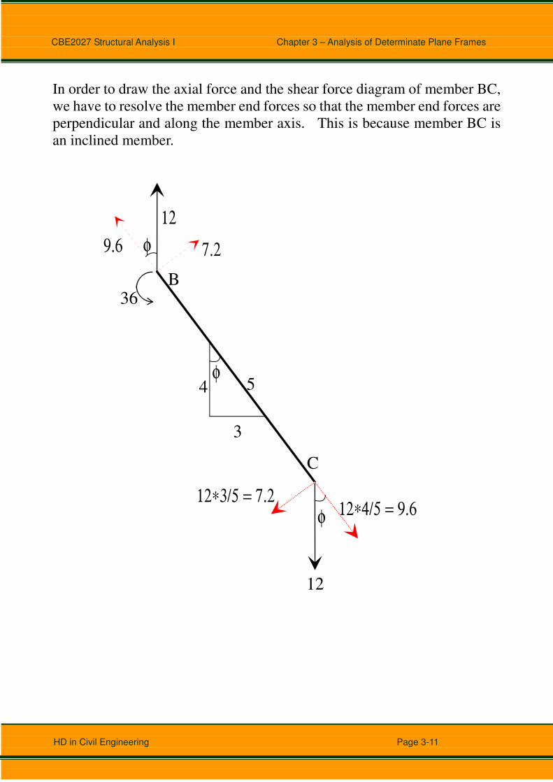
In order to draw the axial force and the shear force diagram of member BC,
we have to resolve the member end forces so that the member end forces are
perpendicular and along the member axis. This is because member BC is
an inclined member.
B
C
36
12
3
4 5φ
φ
φ
12∗4/5 = 9.612∗3/5 = 7.2
12
7.29.6

CBE2027 Structural Analysis I Chapter 3 – Analysis of Determinate Plane Frames
HD in Civil Engineering Page 3-12
Axial force, shear force and bending moment diagrams
A B
C
9.6
9.6
Axial Force (kN)
A B
C
7.2
Shear Force (kN)
12 12
7.2
A B
C
Bending Moment (kNm)
-108
-36-36
0
+

CBE2027 Structural Analysis I Chapter 3 – Analysis of Determinate Plane Frames
HD in Civil Engineering Page 3-13
Example 3
Determine the support reactions, and draw the axial force, shear force and
bending moment diagrams for the frame. Joints C and E are rigid joints.
A
B
CD
E
F
96 kN
48 kN
3m
5m
4.5
m3
m
3m

CBE2027 Structural Analysis I Chapter 3 – Analysis of Determinate Plane Frames
HD in Civil Engineering Page 3-14
Solution:
HA V
A
VF
A
B
CD
E
F
96 kN
48 kN
3m
5m
4.5
m3
m
3m
∑X = 0, HA = 48 kN
Take moment about A,
48*4.5 + 96*3 = VF*6, ⇒ VF = 84 kN
∑Y = 0, VA + VF = 96 kN ⇒ VA = 12 kN

CBE2027 Structural Analysis I Chapter 3 – Analysis of Determinate Plane Frames
HD in Civil Engineering Page 3-15
Free-body diagrams for the members and joints, and their member end
forces.
B
C
D
E
96 kN
48 kN
C12
216
12
216
E84
84
A
F
1248
84
12
216
12
216
84
84
Free-body Diagrams
C E

CBE2027 Structural Analysis I Chapter 3 – Analysis of Determinate Plane Frames
HD in Civil Engineering Page 3-16
Axial force, shear force and bending moment diagrams
B
C
D
E
A
F
Axial Force (kN)
-12
-12
-84
-84
-
-
B
C
D E
A
F
Shear Force (kN)
48
12
-84
48
12
-84

CBE2027 Structural Analysis I Chapter 3 – Analysis of Determinate Plane Frames
HD in Civil Engineering Page 3-17
B
C D E
A
F
Bending Moment (kNm)
216
252
216
216
CBE2027 Structural Analysis I Chapter 3 – Analysis of Determinate Plane Frames
HD in Civil Engineering Page 3-18
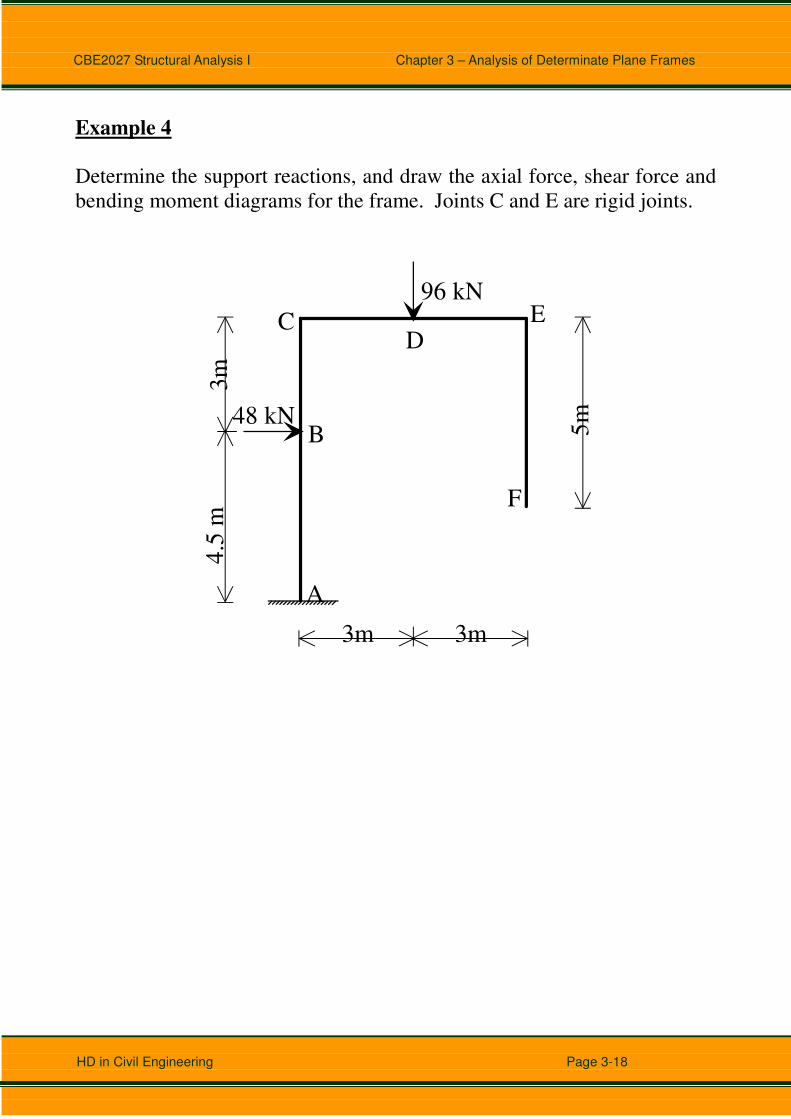
Example 4
Determine the support reactions, and draw the axial force, shear force and
bending moment diagrams for the frame. Joints C and E are rigid joints.
A
B
CD
E
F
96 kN
48 kN
3m
5m
4.5
m3
m
3m
CBE2027 Structural Analysis I Chapter 3 – Analysis of Determinate Plane Frames
HD in Civil Engineering Page 3-19
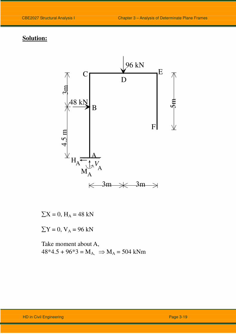
Solution:
A
B
CD
E
F
96 kN
48 kN
3m
5m
4.5
m3
m
3m
HA VA
MA
∑X = 0, HA = 48 kN
∑Y = 0, VA = 96 kN
Take moment about A,
48*4.5 + 96*3 = MA, ⇒ MA = 504 kNm
CBE2027 Structural Analysis I Chapter 3 – Analysis of Determinate Plane Frames
HD in Civil Engineering Page 3-20
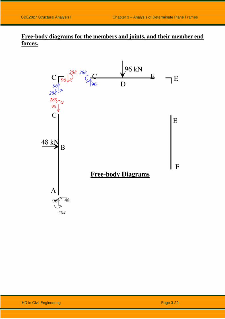
Free-body diagrams for the members and joints, and their member end
forces.
B
C
D
E
96 kN
48 kN
C96
288
96
288
E
A
F
96 48
96
288
96
288
Free-body Diagrams
504
C E
CBE2027 Structural Analysis I Chapter 3 – Analysis of Determinate Plane Frames
HD in Civil Engineering Page 3-21
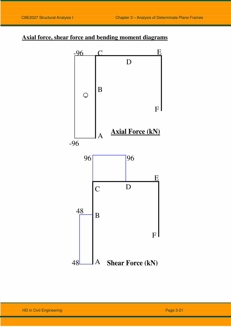
Axial force, shear force and bending moment diagrams
B
C
D
E
A
F
Axial Force (kN)
-
-96
-96
B
C D
E
A
F
Shear Force (kN)
48
96 96
48

CBE2027 Structural Analysis I Chapter 3 – Analysis of Determinate Plane Frames
HD in Civil Engineering Page 3-22
B
C D
E
A
F
Bending Moment (kNm)-504
-288
-288
-288
0

CBE2027 Structural Analysis I Chapter 3 – Analysis of Determinate Plane Frames
HD in Civil Engineering Page 3-23
Example 5
Determine the support reactions, and draw the axial force, shear force and
bending moment diagrams for the frame. Joints B and C are rigid joints.
20 kN
50 kN15 kN/m
A
B C
D
E
8m
6m
2m
2m

CBE2027 Structural Analysis I Chapter 3 – Analysis of Determinate Plane Frames
HD in Civil Engineering Page 3-24
Solution:
HA V
A
VE
20 kN
50 kN15 kN/m
A
B C
D
E
8m
6m
2m
2m
∑X = 0, HA + 20 = 50, ⇒ HA = 30 kN
Take moment about A,
50*6 + 15*8*8/2 – 20*4 – VE*8 = 0
⇒ VE = 87.5 kN
∑Y = 0, VA + VE = 15*8 kN, ⇒ VA = 32.5 kN

CBE2027 Structural Analysis I Chapter 3 – Analysis of Determinate Plane Frames
HD in Civil Engineering Page 3-25
Free-body diagrams for the members and joints, and their member end
forces.
50 kN15 kN/m
B C
20 kN
C
D
E
87.5
30A
B
32.5
B
32.5
180
32.5180
3020
87.5
40
87.540
2020
C
32.5
180
30
32.5
18020
87.5
40
20
40
20
87.5
Free-body Diagrams
Axial force, shear force and bending moment diagrams
B C
D
A
E
-32.5
-32.5
-20 -20-87.5
-87.5
-
-
-
Axial Force (kN)

CBE2027 Structural Analysis I Chapter 3 – Analysis of Determinate Plane Frames
HD in Civil Engineering Page 3-26
B C
D
A
E
Shear Force (kN)
30
30
32.5
-87.5
20
20
2.17m
B C
D
A
E
Bending Moment (kNm)
-40 -40180
180
215.2
2.17m

CBE2027 Structural Analysis I Chapter 3 – Analysis of Determinate Plane Frames
HD in Civil Engineering Page 3-27
Example 6
Determine the support reactions, and draw the axial force, shear force and
bending moment diagrams for the frame. Joints B and D are rigid joints.
30 kN
10 kN
5kN/m A
B
CD
E
F
3.5m 3.5m
3m
3m
8m

CBE2027 Structural Analysis I Chapter 3 – Analysis of Determinate Plane Frames
HD in Civil Engineering Page 3-28
Solution:
HA V
A
VF
30 kN
10 kN
5kN/m A
B
CD
E
F
3.5m 3.5m3
m3
m
8m
∑X = 0, HA + 10 = 5*8/2, ⇒ HA = 10 kN
Take moment about A,
5*(8/2)*(8/3) + 30*3.5 - 10*(3+2) – VF*7 = 0
⇒ VF = 15.5 kN
∑Y = 0, VA + VF = 30 kN, ⇒ VA = 14.5 kN

CBE2027 Structural Analysis I Chapter 3 – Analysis of Determinate Plane Frames
HD in Civil Engineering Page 3-29
Free-body diagrams for the members and joints, and their member end
forces.
30 kN
10 kN
5kN/m A
B
C
D
E
F
15.5kN
14.5kN10kN
DB
B
14.526.7
14.5
26.7
10 10
15.5
30
15.5
30
1010C
14.526.7
10
14.510
26.7
15.5
30
10
15.5
3010
Free-body Diagrams

CBE2027 Structural Analysis I Chapter 3 – Analysis of Determinate Plane Frames
HD in Civil Engineering Page 3-30
Axial force, shear force and bending moment diagrams
Determination of the position of zero shear force and the maximum bending
moment of member AB.
B
14.5 26.7
10
x
5x/8 kN/m
14.5
M
V
Free-body Diagram for Part of Member AB
Consider the free-body diagram for part of member AB. The loading
intensity of the triangular load = (5x/8) kN/m. Set V = 0, and determine x.
To determine the position of zero shear force (i.e. V = 0 kN), take moment
about the “cut”,
∑Y = 0, (5x/8)*(x/2) – 10 = 0, ⇒ x = 5.66 m
To determine the value of maximum moment of member AB, consider
∑M = 0, M + 26.7 + (5*5.66/8)*(5.66/2)*(5.66/3) – 10*5.66 = 0
⇒ M = 11.0 kNm
To determine the position of zero moment of member AB, we have to use
“trial and error” method to solve a cubic equation. Consider the free-body
diagram for part of member AB. Set M = 0, to determine x
∑M = 0, 26.7 + (5*x/8)*(x/2)*(x/3) – 10*x = 0
⇒ 0.1042x3 – 10x + 26.7 = 0
Solving this equation by “trial and error”, we get x = 2.93m.

CBE2027 Structural Analysis I Chapter 3 – Analysis of Determinate Plane Frames
HD in Civil Engineering Page 3-31
B
C
D
E
F
A
-
-
-
Axial Force (kN)-14.5
-14.5
-10 -10
-15.5
-15.5
B C D
E
F
A Shear Force (kN)
14.5 14.5
-15.5
10
10
10
2.3
4m
5.6
6m
-10

CBE2027 Structural Analysis I Chapter 3 – Analysis of Determinate Plane Frames
HD in Civil Engineering Page 3-32
BC D
E
F
A Bending Moment (kNm)
2.3
4m
-30
-30-26.7
24.3
-26.7
2.9
3m
11.0

CBE2027 Structural Analysis I Chapter 3 – Analysis of Determinate Plane Frames
HD in Civil Engineering Page 3-33
Example 7
Determine the support reactions, and draw the axial force, shear force and
bending moment diagrams for the frame. Joint B is a rigid joint and joint C
is an internal hinge of the frame.
A
B C
D
6m
4m
30 kN15 kN/m

CBE2027 Structural Analysis I Chapter 3 – Analysis of Determinate Plane Frames
HD in Civil Engineering Page 3-34
Solution:
HA
VA
HD
VD
A
B C
D
6m
4m
30 kN15 kN/m
Take moment about A,
30*4 + 15*6*6/2 – VD*6 = 0
⇒ VD = 65 kN
∑Y = 0, VA + VD = 15*6 kN, ⇒ VA = 25 kN
Consider the free-body of CD,
65HD
65HC
C
D
Take moment about C,
HD*4 = 0, ⇒ HD = 0 kN
∑X = 0, HA + HD = 30, ⇒ HA = 30 kN
CBE2027 Structural Analysis I Chapter 3 – Analysis of Determinate Plane Frames
HD in Civil Engineering Page 3-35
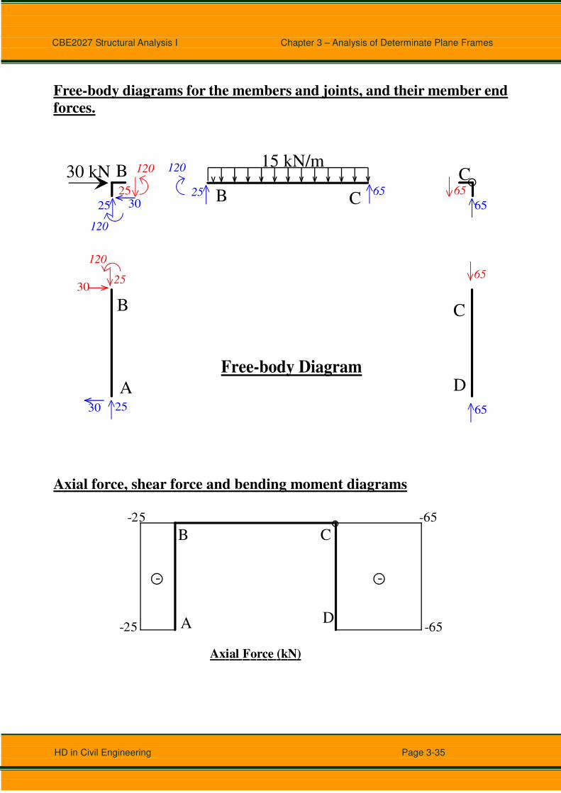
Free-body diagrams for the members and joints, and their member end
forces.
A
B C
D
30 kN15 kN/m
CB
B
25
120
25
120
30 65
65
C
2530 65
6525
120
30
6525
120
Free-body Diagram
Axial force, shear force and bending moment diagrams
A
B C
D
-25 -65
-65-25
Axial Force (kN)
- -

CBE2027 Structural Analysis I Chapter 3 – Analysis of Determinate Plane Frames
HD in Civil Engineering Page 3-36
A
B C
D
Shear Force (kN)
30
30
25
-65
1.67m
A
B C
D
Bending Moment (kNm)
1.67m
120
120
140.9

CBE2027 Structural Analysis I Chapter 3 – Analysis of Determinate Plane Frames
HD in Civil Engineering Page 3-37
Example 8
Determine the support reactions, and draw the axial force, shear force and
bending moment diagrams for the frame. Joints B and C are rigid joints,
and joint E is an internal hinge of the frame.
A
B C
D
EF
3m
4m
4m 4m
20 kN
3 k
N/m
CBE2027 Structural Analysis I Chapter 3 – Analysis of Determinate Plane Frames
HD in Civil Engineering Page 3-38
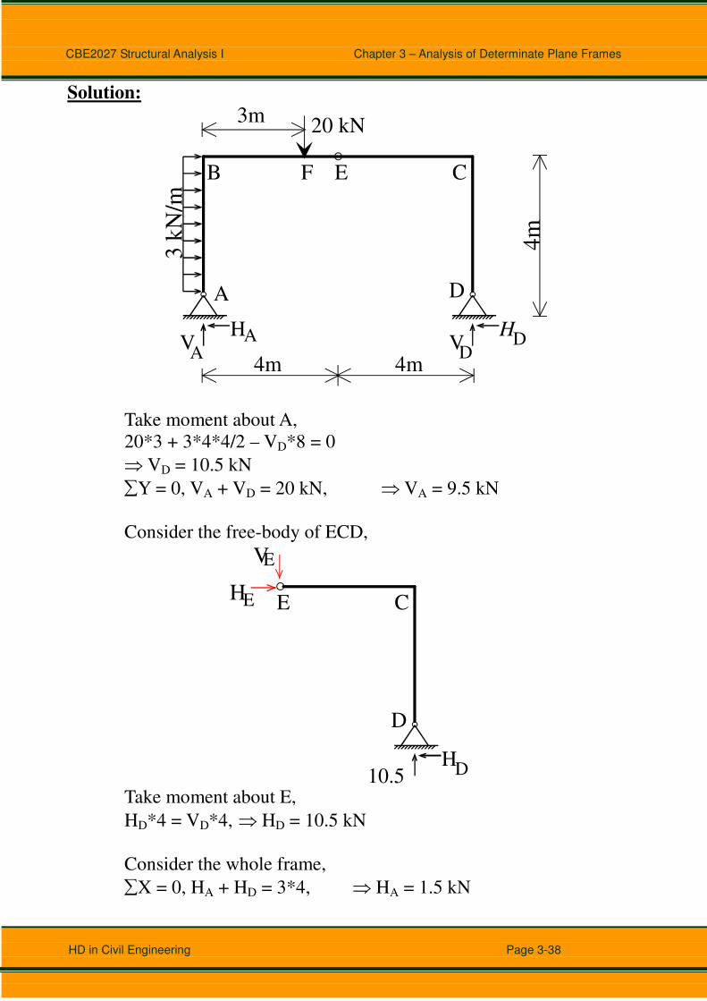
Solution:
HAVA
HDV
D
A
B C
D
EF
3m
4m
4m 4m
20 kN
3 k
N/m
Take moment about A,
20*3 + 3*4*4/2 – VD*8 = 0
⇒ VD = 10.5 kN
∑Y = 0, VA + VD = 20 kN, ⇒ VA = 9.5 kN
Consider the free-body of ECD,
HD 10.5
C
D
EHE
VE
Take moment about E,
HD*4 = VD*4, ⇒ HD = 10.5 kN
Consider the whole frame,
∑X = 0, HA + HD = 3*4, ⇒ HA = 1.5 kN

CBE2027 Structural Analysis I Chapter 3 – Analysis of Determinate Plane Frames
HD in Civil Engineering Page 3-39
Free-body diagrams for the members and joints, and their member end
forces.
A
B C
D
EF
20 kN
3 k
N/m
B
9.5
18
9.5
18
10.5 10.5
10.5
42
10.54210.5
10.5 C
9.51.510.5
10.5
9.5
18
10.5
10.5
42
10.5
10.54210.5
9.5
18 10.5
Free-body Diagrams
B C

CBE2027 Structural Analysis I Chapter 3 – Analysis of Determinate Plane Frames
HD in Civil Engineering Page 3-40
Axial force, shear force and bending moment diagrams
C
D
EF
A
B
-10.5-10.5
-10.5
-10.5
-9.5
-9.5
-
--
Axial Force (kN)
C
D
E
F
A
B
Shear Force (kN)1.5
-10.5
9.5 9.5
-10.5 -10.5
10.5
10.5 0.5
m

CBE2027 Structural Analysis I Chapter 3 – Analysis of Determinate Plane Frames
HD in Civil Engineering Page 3-41
C
D
E
F
A
B
Bending Moment (kNm)
0.5
m
-42
-42
-18
-18
10.5
0.375

CBE2027 Structural Analysis I Chapter 3 – Analysis of Determinate Plane Frames
HD in Civil Engineering Page 3-42
Example 9
Determine the support reactions, and draw the axial force, shear force and
bending moment diagrams for the frame. Joints B and E are rigid joints, and
joint D is an internal hinge of the frame.
A
BC D
E
F
4m
6m
40 kN
5 k
N/m
1m 2m 3m
CBE2027 Structural Analysis I Chapter 3 – Analysis of Determinate Plane Frames
HD in Civil Engineering Page 3-43
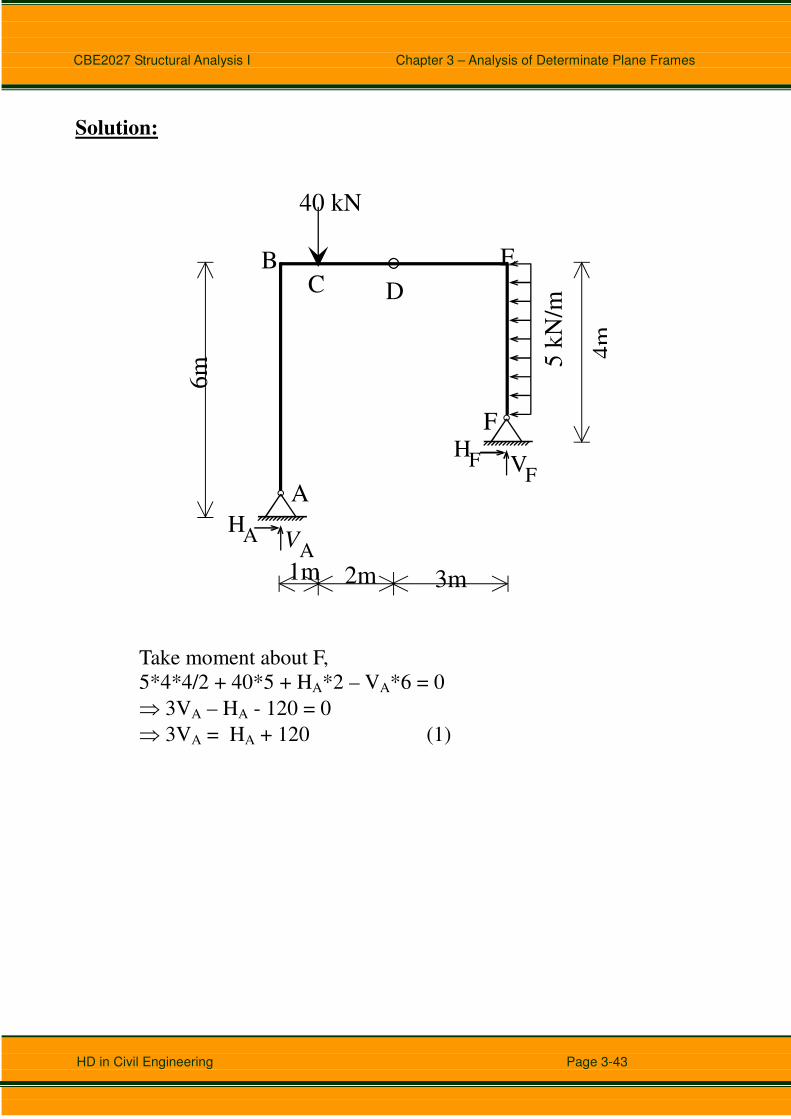
Solution:
HA V
A
HF V
FA
BC D
E
F
4m
6m
40 kN
5 k
N/m
1m 2m 3m
Take moment about F,
5*4*4/2 + 40*5 + HA*2 – VA*6 = 0
⇒ 3VA – HA - 120 = 0
⇒ 3VA = HA + 120 (1)
CBE2027 Structural Analysis I Chapter 3 – Analysis of Determinate Plane Frames
HD in Civil Engineering Page 3-44
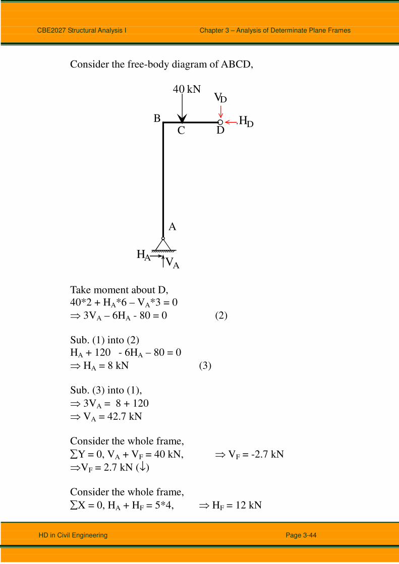
Consider the free-body diagram of ABCD,
HA VA
A
BC D
40 kN
H
V
D
D
Take moment about D,
40*2 + HA*6 – VA*3 = 0
⇒ 3VA – 6HA - 80 = 0 (2)
Sub. (1) into (2)
HA + 120 - 6HA – 80 = 0
⇒ HA = 8 kN (3)
Sub. (3) into (1),
⇒ 3VA = 8 + 120
⇒ VA = 42.7 kN
Consider the whole frame,
∑Y = 0, VA + VF = 40 kN, ⇒ VF = -2.7 kN
⇒VF = 2.7 kN (↓)
Consider the whole frame,
∑X = 0, HA + HF = 5*4, ⇒ HF = 12 kN

CBE2027 Structural Analysis I Chapter 3 – Analysis of Determinate Plane Frames
HD in Civil Engineering Page 3-45
Free-body diagrams for the members and joints, and their member end
forces.
A
B
C D
E
F
40 kN5
kN
/m
E
B
42.78
2.712
B
42.7
48
42.7
48
8 8
2.7
8
2.7
8
88E
42.7
48
8
2.7
8
8
2.7
8
842.7
48
8
Free-body Diagrams
Axial force, shear force and bending moment diagrams
A
BC D
E
F
-8 -8-42.7
-42.7
2.7
2.7
Axial Force (kN)
-
+-

CBE2027 Structural Analysis I Chapter 3 – Analysis of Determinate Plane Frames
HD in Civil Engineering Page 3-46
A
B C
D
E
F
Shear Force (kN)
-8
-8
42.7 42.7
2.7 2.78
-12
2.4
m
A
B C
D
E
F
Bending Moment (kNm)
2.4
m
-48
-48
-5.3
8
8
14.4

CBE2027 Structural Analysis I Chapter 3 – Analysis of Determinate Plane Frames
HD in Civil Engineering Page 3-47
Tutorial 3 (Analysis of Frames)
Find the support reactions, and draw the axial force diagram, shear force
diagram and bending moment diagram for the frames shown below.
Q1.
6m
5m
2.5
m2
.5m
30 kN
6 kN/m
A
B
C D
E
Q2.
1.5m 1.5m2m
50 kN 40 kN
4m
6m
15
kN
/m
A
B C D E
F
E is an internal hinge
CBE2027 Structural Analysis I Chapter 3 – Analysis of Determinate Plane Frames
HD in Civil Engineering Page 3-48
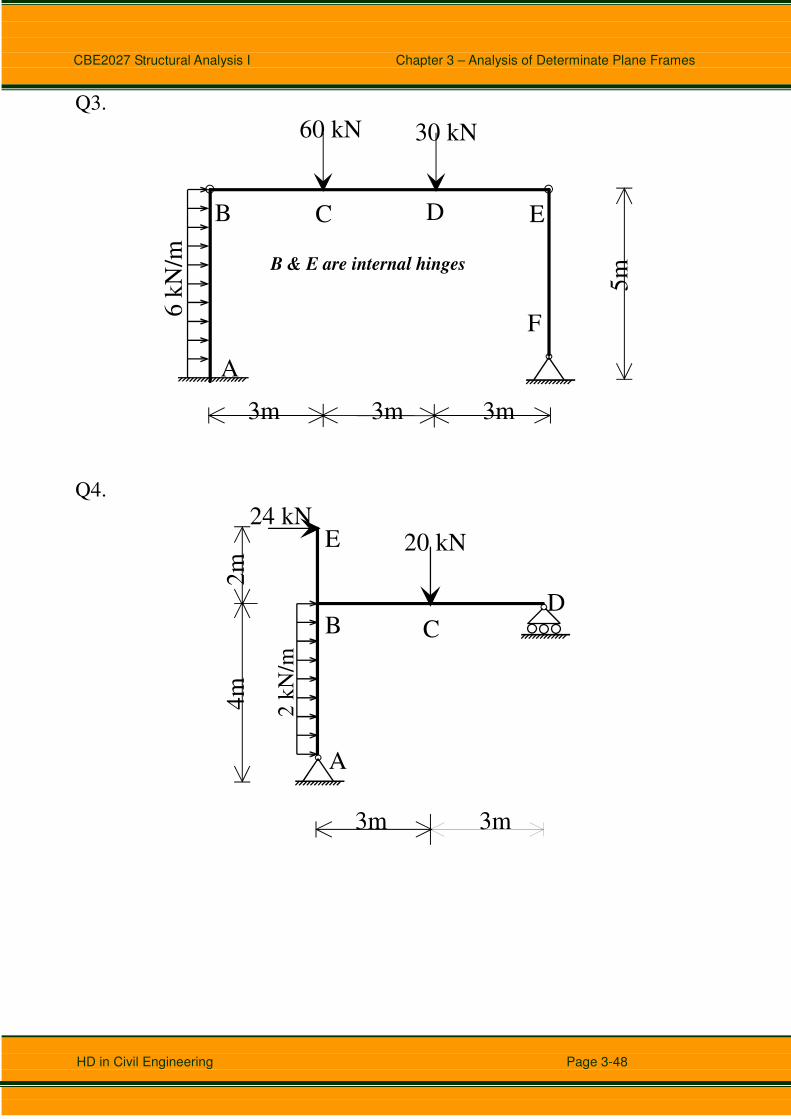
Q3.
3m 3m 3m
5m
60 kN 30 kN
6 k
N/m
A
B C D E
F
B & E are internal hinges
Q4.
3m 3m
4m
2m
20 kN24 kN
A
B CD
E
2 k
N/m
CBE2027 Structural Analysis I Chapter 3 – Analysis of Determinate Plane Frames
HD in Civil Engineering Page 3-49
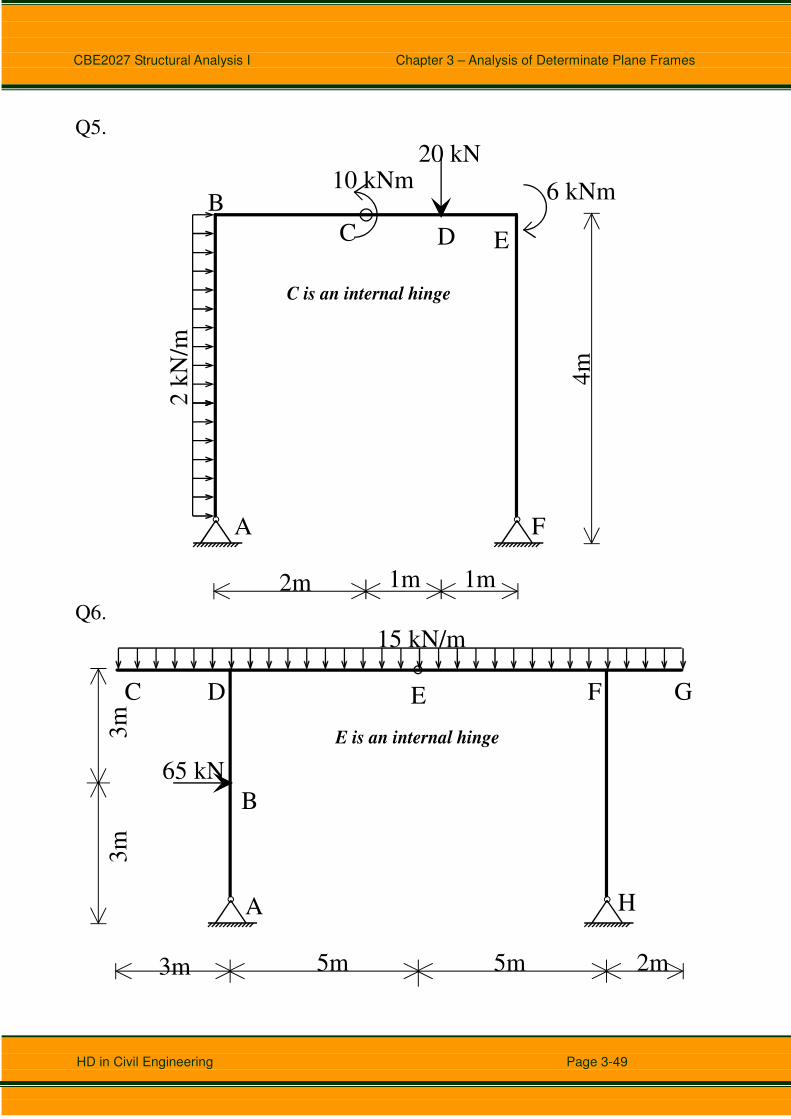
Q5.
2 k
N/m
20 kN
2m 1m 1m4
m
B
A
C D E
F
6 kNm 10 kNm
C is an internal hinge
Q6.
A
B
C D E F G
H
15 kN/m
65 kN
3m 5m 2m5m
3m
3m
E is an internal hinge

CBE2027 Structural Analysis I Chapter 3 – Analysis of Determinate Plane Frames
HD in Civil Engineering Page 3-50
Q7.
3m 3m
3m
3m
A
B
C D E
F
G
30 kN10 kN/m
B, D & F are internal hinges
Q8.
3 kN/m
2 kN/m
3m 3m
4m
6m
A
B C D
E
C is an internal hinge

CBE2027 Structural Analysis I Chapter 3 – Analysis of Determinate Plane Frames
HD in Civil Engineering Page 3-51
Q9.
200 kN
100 kN
3m 4m
3m
3m
A
B
C
E
D
C is an internal hinge
Q10.
4 kN/m
4m 4m
4m
6m
A
B C
D