Embed Size (px)
Citation preview
CON4332 REINFORCED CONCRETE DESIGN
Chapter 4 1
HD in Civil Engineering (Aug 2014)
│CHAPTER 4│
Design of R C Beams
Learning Objectives
Identify the data, formulae and procedures for design of R C beams
Design simply-supported and continuous R C beams by integrating the following processes
o determining design loads
o determining design forces by force coefficients
o determining reinforcement for bending and shear
o checking deflection by span-to-depth ratio
CONTENTS
4.1 Design Data, Formulae and Procedures 4.1.1 Design Forces
4.1.2 Force Coefficients
4.1.3 Design for Moment and Shear
4.1.4 Deflection Check by Span-to-depth Ratio
4.2 Simply-supported Beams 4.2.1 Example – Simply-supported Rectangular Beam
4.2.2 Examples – Simply-supported Flanged Beam
4.2.3 Notes on Detailing
4.3 Continuous Beams 4.3.1 Example – Uniformly Loaded & Equal Span
4.3.2 Examples – Continuous Beam with Design Force Envelopes
CON4332 REINFORCED CONCRETE DESIGN
Chapter 4 2
HD in Civil Engineering (Aug 2014)
4.1 Design Data, Formulae and Procedures
A beam is generally referred to a horizontal element designed to take up
gravitational load, and, although it may be designed as an integral of a
structural frame to resist lateral load, the predominant design forces for a
beam are bending moment, M, and shear force, V.1
The design data, formulae and rules that you have learnt in Chapters 1 to 3,
which are summarized in the "Annex – R C Design Formulae and Data", will
be adopted in this Chapter. You will learn how to integrate and apply them
to carry out the whole process of design calculations for a beam.
The basic steps in designing of R C beams are:
I. Determine the design loads
II. Determine the design forces
III. Determine the reinforcement
IV. Check deflection
V. Detailing
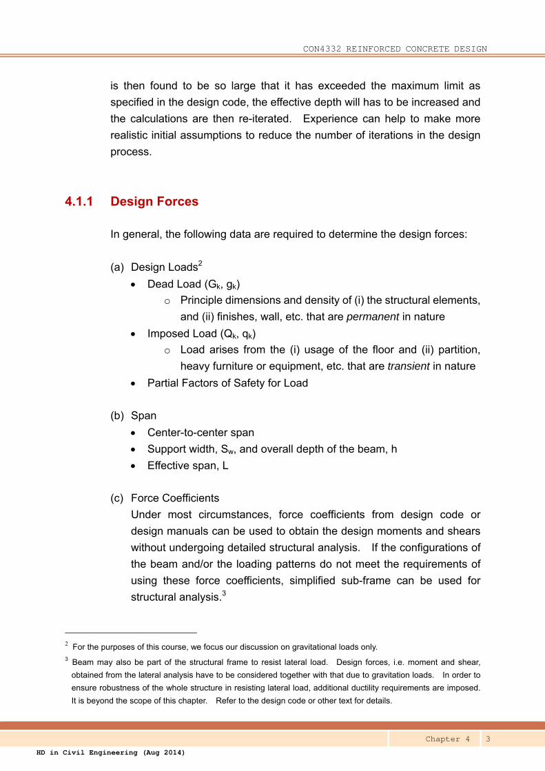
In the each of the above step, we
have to identify the necessary data or
design parameters for inputting into
appropriate formulae to get the
required results and then to check for
compliance with the design code.
Some data may have to be assumed
first and then to be verified when the
result is available. The whole
process always requires several
iterations. For example, the effective
depth of the section has to be
assumed to calculate the steel area
required, and if the steel area required
1 Beam may also be subjected to torsion and axial load. They are beyond the scope in this chapter. Refer to
the design code for details.
Assumed + Prescribed Parameters
Result
CON4332 REINFORCED CONCRETE DESIGN
Chapter 4 3
HD in Civil Engineering (Aug 2014)
is then found to be so large that it has exceeded the maximum limit as
specified in the design code, the effective depth will has to be increased and
the calculations are then re-iterated. Experience can help to make more
realistic initial assumptions to reduce the number of iterations in the design
process.
4.1.1 Design Forces
In general, the following data are required to determine the design forces:
(a) Design Loads2
Dead Load (Gk, gk)
o Principle dimensions and density of (i) the structural elements,
and (ii) finishes, wall, etc. that are permanent in nature
Imposed Load (Qk, qk)
o Load arises from the (i) usage of the floor and (ii) partition,
heavy furniture or equipment, etc. that are transient in nature
Partial Factors of Safety for Load
(b) Span
Center-to-center span
Support width, Sw, and overall depth of the beam, h
Effective span, L
(c) Force Coefficients
Under most circumstances, force coefficients from design code or
design manuals can be used to obtain the design moments and shears
without undergoing detailed structural analysis. If the configurations of
the beam and/or the loading patterns do not meet the requirements of
using these force coefficients, simplified sub-frame can be used for
structural analysis.3
2 For the purposes of this course, we focus our discussion on gravitational loads only. 3 Beam may also be part of the structural frame to resist lateral load. Design forces, i.e. moment and shear,
obtained from the lateral analysis have to be considered together with that due to gravitation loads. In order to
ensure robustness of the whole structure in resisting lateral load, additional ductility requirements are imposed.
It is beyond the scope of this chapter. Refer to the design code or other text for details.
CON4332 REINFORCED CONCRETE DESIGN
Chapter 4 4
HD in Civil Engineering (Aug 2014)
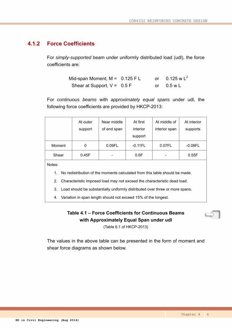
4.1.2 Force Coefficients
For simply-supported beam under uniformly distributed load (udl), the force
coefficients are:
Mid-span Moment, M = 0.125 F L or 0.125 w L2
Shear at Support, V = 0.5 F or 0.5 w L
For continuous beams with approximately equal spans under udl, the
following force coefficients are provided by HKCP-2013:
At outer
support
Near middle
of end span
At first
interior
support
At middle of
interior span
At interior
supports
Moment 0 0.09FL -0.11FL 0.07FL -0.08FL
Shear 0.45F - 0.6F - 0.55F
Notes:
1. No redistribution of the moments calculated from this table should be made.
2. Characteristic imposed load may not exceed the characteristic dead load.
3. Load should be substantially uniformly distributed over three or more spans.
4. Variation in span length should not exceed 15% of the longest.
Table 4.1 – Force Coefficients for Continuous Beams
with Approximately Equal Span under udl
(Table 6.1 of HKCP-2013)
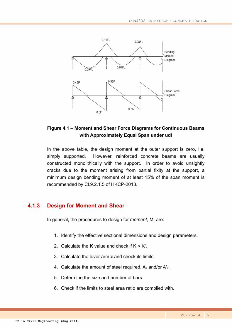
The values in the above table can be presented in the form of moment and
shear force diagrams as shown below.
CON4332 REINFORCED CONCRETE DESIGN
Chapter 4 5
HD in Civil Engineering (Aug 2014)
0.09FL
0.11FL
0.07FL
0.08FL
0.45F
0.6F
0.55F
0.55F
Bending Moment Diagram
Shear Force Diagram
Figure 4.1 – Moment and Shear Force Diagrams for Continuous Beams
with Approximately Equal Span under udl
In the above table, the design moment at the outer support is zero, i.e.
simply supported. However, reinforced concrete beams are usually
constructed monolithically with the support. In order to avoid unsightly
cracks due to the moment arising from partial fixity at the support, a
minimum design bending moment of at least 15% of the span moment is
recommended by Cl.9.2.1.5 of HKCP-2013.
4.1.3 Design for Moment and Shear
In general, the procedures to design for moment, M, are:
1. Identify the effective sectional dimensions and design parameters.
2. Calculate the K value and check if K < K'.
3. Calculate the lever arm z and check its limits.
4. Calculate the amount of steel required, As and/or A's.
5. Determine the size and number of bars.
6. Check if the limits to steel area ratio are complied with.
CON4332 REINFORCED CONCRETE DESIGN
Chapter 4 6
HD in Civil Engineering (Aug 2014)
In general, the procedures to design for shear, V, are:
1. Identify the effective sectional dimensions and design parameters.
2. Calculate the maximum shear at the faces of the supports, Vs.
3. Check if the shear stress vs exceeds the maximum allowable shear
stress, i.e. 0.8√fcu.
If vs < 0.8√fcu, proceed to next step
If vs > 0.8√fcu, increase the size of the section
4. Calculate the shear forces at d from the faces of the supports, Vd.
5. Calculate vc.
6. Check if the shear stress vd exceeds vc + 0.4.
If vd < vc +0.4, provide nominal link.
If vd > vc +0.4, provide shear link and determine the extent.
7. Determine the size and spacing of the links.
8. Check if the limits to spacing of links are complied with.
4.1.4 Deflection Check by Span-to-depth Ratio
In general, the procedures to check deflection by span-to-depth ratio are:
1. Determine the basic L/d ratio.
2. Determine the modification factors, ml, mt & mc.
3. Determine the allowable L/d ratio.
4. Check if the actual L/d ratio exceeds the allowable or not.
CON4332 REINFORCED CONCRETE DESIGN
Chapter 4 7
HD in Civil Engineering (Aug 2014)
4.2 Simply-supported Beams
The whole design process of a simply-supported beam is illustrated by three
examples in this section. They show you how to integrate what you have
learnt in the previous chapters. The basic procedures of the design are:
1. Determine the effective span, L, a1 & a2
2. Determine the design load and forces, M & V
3. Determine the effective dimensions, d, beff, bw, bv.
4. Design the bars for mid-span moment
5. Design for the shear at supports
6. Check deflection by span-to-depth ratio
The example in 4.2.1 demonstrates the basic process to design a simple
rectangular beam.
Two examples in 4.2.2 provide a more realistic illustration on the whole
process of design. A beam from the framing plan in DWG-01 is used as a
demonstration. It is a flanged section. Calculations of loading and
determination of effective flange width are included in the design process.
The beam is then re-designed with some changes: the beam depth is
reduced and additional load is imposed. You can appreciate the
implications of these changes on the design. The reinforcement details of
the beams are presented as DWG-02 at the end of this Chapter.
4.2.1 Example – Simply-supported Rectangular Beam
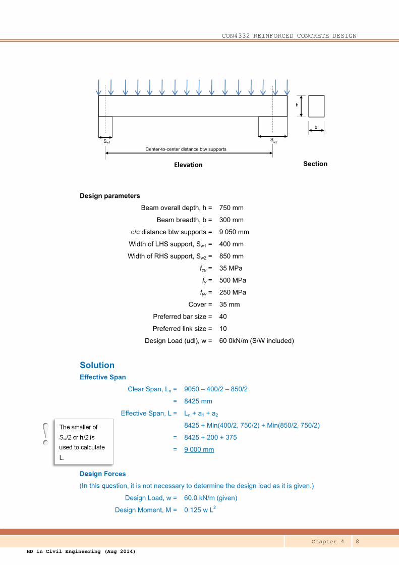
Question A rectangular beam simply supported at both ends as shown below. Design the
reinforcement and check if the deflection is acceptable or not.
CON4332 REINFORCED CONCRETE DESIGN
Chapter 4 8
HD in Civil Engineering (Aug 2014)
Elevation
h
Sw1 Sw2
Center-to-center distance btw supports
Section
b
Design parameters
Beam overall depth, h = 750 mm
Beam breadth, b = 300 mm
c/c distance btw supports = 9 050 mm
Width of LHS support, Sw1 = 400 mm
Width of RHS support, Sw2 = 850 mm
fcu = 35 MPa
fy = 500 MPa
fyv = 250 MPa
Cover = 35 mm
Preferred bar size = 40
Preferred link size = 10
Design Load (udl), w = 60 0kN/m (S/W included)
Solution Effective Span
Clear Span, Ln = 9050 – 400/2 – 850/2
= 8425 mm
Effective Span, L = Ln + a1 + a2
8425 + Min(400/2, 750/2) + Min(850/2, 750/2)
= 8425 + 200 + 375
= 9 000 mm
Design Forces
(In this question, it is not necessary to determine the design load as it is given.)
Design Load, w = 60.0 kN/m (given)
Design Moment, M = 0.125 w L2
The smaller of
Sw/2 or h/2 is
used to calculate
L.
CON4332 REINFORCED CONCRETE DESIGN
Chapter 4 9
HD in Civil Engineering (Aug 2014)
= 0.125 x 60.0 x 92
= 607.5 kN-m
Design Shear, V = 0.5 w L
= 0.5 x 60 x 9
= 270.0 kN
Effective Depth
d = 750 – 35 – 10 – 40/2
= 685 mm
Design for Bending Moment
K = M / (bd2fcu)
= 607.5 x 10⁶ / (300 x 6852 x 35)
= 0.123
βb = 1.0 < 0.156 (Singly reinforced)
Lever arm, z = [0.5 + (0.25 – K/0.9)0.5] d
= [0.5 + (0.25 – 0.123/0.9)0.5] x 685
= 0.837 x 685
= 573 mm
Tension steel req'd, As,req = M / (0.87 fy z)
= 607.5 x 10⁶ / (0.87 x 500 x 573)
= 2 437 mm2
(Provide 2T40)
As,pro = 2 x 1257
= 2 514 mm2
100As / bh = 100 x 2514 / (300 x 750) = 1.117
> 0.13 and < 4.0 (Steel ratio ok)
Design for Shear at Support
Max shear at the face of LHS support
Vs = V – w a1
= 270 – 60 x 200 / 103
= 258 kN
vmax = vs = V / (bvd)
= 258 x 103 / (300 x 685)
= 1.26 MPa
CON4332 REINFORCED CONCRETE DESIGN
Chapter 4 10
HD in Civil Engineering (Aug 2014)
< 0.8 √ 35 = 4.73 MPa (Concrete does not crush)
Shear at d from the face of LHS support
Vd = 258 – w d
= 258 – 60 x 685 / 103
= 217 kN
vd = 217 x 103 / (300 x 685)
= 1.06 MPa
Calculate the design concrete shear stress, vc : (Table 6.3)
100As/(bvd) = 100 x 2514 / (300 x 685) = 1.22 < 3
(400/d)1/4 = (400 / 685)1/4 < 1 (use 1.0)
vc = 0.79 x (1.22)1/3 x (1.0) / 1.25 x (35/25)1/3
= 0.675 x 1.12
= 0.76 MPa
vc + 0.4 = 0.76 + 0.4 = 1.16 MPa
> 1.06 MPa (Provide nominal links)
Nominal Links
Asv / sv = 0.4 x bv / (0.87 fyv)
= 0.4 x 300 / (0.87 x 250)
= 0.552
Max sv < 0.75 x d
= 0.75 x 685 = 514 mm
(Provide R10 – 275 – 2/legs)
Asv / sv, pro = 0.571 > 0.552
Check Deflection by Span-to-depth Ratio
Basic L /d = 20 (Simply-supported Rectangular Beam) (Table 7.3)
M/(bd2) = 607.5 x 10⁶ / (300 x 6852)
= 4.32 N/mm2
As,req / As,pro = 2437 / 2514 = 0.969
fs = 2/3 x 500 x 0.969 = 323 MPa
mt = 0.55 + (477-323)/[120(0.9+4.32)] (Table 7.4)
= 0.55 + 0.246
= 0.796
As pro instead of As req
is used for As in
determining vc
The tables/equations
quoted in the
calculations are
referring to
HKCP-2013.
CON4332 REINFORCED CONCRETE DESIGN
Chapter 4 11
HD in Civil Engineering (Aug 2014)
Allowable L / d = 0.796 x 20 = 15.92
Actual L / d = 9000 / 685
= 13.14 ≤ 15.92 (Deflection ok)
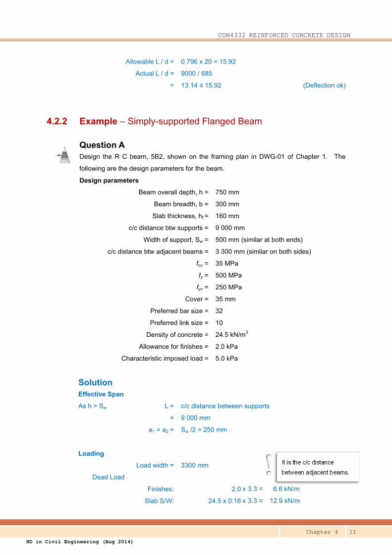
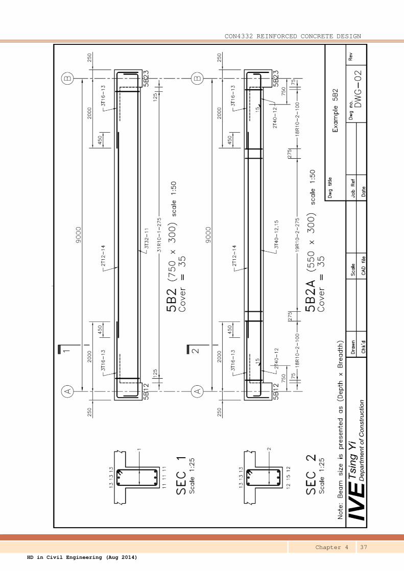
4.2.2 Example – Simply-supported Flanged Beam
Question A Design the R C beam, 5B2, shown on the framing plan in DWG-01 of Chapter 1. The
following are the design parameters for the beam.
Design parameters
Beam overall depth, h = 750 mm
Beam breadth, b = 300 mm
Slab thickness, hf = 160 mm
c/c distance btw supports = 9 000 mm
Width of support, Sw = 500 mm (similar at both ends)
c/c distance btw adjacent beams = 3 300 mm (similar on both sides)
fcu = 35 MPa
fy = 500 MPa
fyv = 250 MPa
Cover = 35 mm
Preferred bar size = 32
Preferred link size = 10
Density of concrete = 24.5 kN/m3
Allowance for finishes = 2.0 kPa
Characteristic imposed load = 5.0 kPa
Solution Effective Span
As h > Sw L = c/c distance between supports
= 9 000 mm
a1 = a2 = Sw /2 = 250 mm
Loading
Load width = 3300 mm
Dead Load
Finishes: 2.0 x 3.3 = 6.6 kN/m
Slab S/W: 24.5 x 0.16 x 3.3 = 12.9 kN/m
It is the c/c distance
between adjacent beams.
CON4332 REINFORCED CONCRETE DESIGN
Chapter 4 12
HD in Civil Engineering (Aug 2014)
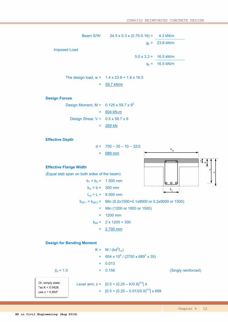
beff
bw
h d
hf x
Beam S/W: 24.5 x 0.3 x (0.75-0.16) = 4.3 kN/m
gk = 23.8 kN/m
Imposed Load
5.0 x 3.3 = 16.5 kN/m
qk = 16.5 kN/m
The design load, w = 1.4 x 23.8 + 1.6 x 16.5
= 59.7 kN/m
Design Forces
Design Moment, M = 0.125 x 59.7 x 92
= 604 kN-m
Design Shear, V = 0.5 x 59.7 x 9
= 269 kN
Effective Depth
d = 750 – 35 – 10 – 32/2
= 689 mm
Effective Flange Width
(Equal slab span on both sides of the beam)
b1 = b2 = 1 500 mm
bw = b = 300 mm
Lpi = L = 9 000 mm
beff,1 = beff,2 = Min (0.2x1500+0.1x9000 or 0.2x9000 or 1500)
= Min (1200 or 1800 or 1500)
= 1200 mm
beff = 2 x 1200 + 300
= 2 700 mm
Design for Bending Moment
K = M / (bd2fcu)
= 604 x 106 / (2700 x 6892 x 35)
= 0.013
βb = 1.0 < 0.156 (Singly reinforced)
Lever arm, z = [0.5 + (0.25 – K/0.9)0.5] d
= [0.5 + (0.25 – 0.013/0.9)0.5] x 689
Or, simply state:
"as K < 0.0428,
use z = 0.95d"
CON4332 REINFORCED CONCRETE DESIGN
Chapter 4 13
HD in Civil Engineering (Aug 2014)
= 0.985 x 689 (use 0.95 x 689)
= 655 mm
Check neutral axis, x = (689 – 655)/0.45
= 76 < 160 mm (N.A. is within the flange)
Tension steel req'd, As,req = M / (0.87 fy z)
= 604 x 106 / (0.87 x 500 x 655)
= 2 120 mm2
(Provide 3T32)
As,pro = 3 x 804
= 2 412 mm2
100As / bh = 100 x 2412 / (300 x 750) = 1.072
> 0.18 and < 4.0 (Steel ratio ok)
Design for Shear at Support
(As this beam is symmetrical, shears at both ends are the same.)
Max shear at the face of support
Vs = V – w ai
= 269 – 59.7 x 250 / 103
= 254 kN
vmax = vs = 254 x 103 / (300 x 689)
= 1.23 MPa
< 0.8 √ 35 = 4.73 MPa (Concrete does not crush)
Shear at d from the face of support
Vd = 254 – w d
= 254 – 59.7 x 689 / 103
= 213 kN
vd = 213 x 103 / (300 x 689)
= 1.03 MPa
Calculate the design concrete shear stress, vc : (Table 6.3)
100As/(bvd) = 100 x 2412 / (300 x 689) = 1.17 < 3
(400/d) = (400 / 689)1/4 < 1 (use 1.0)
vc = 0.79 x (1.17)1/3 x (1.0) / 1.25 x (35/25)1/3
= 0.666 x 1.12
= 0.746 MPa
bv = bw
CON4332 REINFORCED CONCRETE DESIGN
Chapter 4 14
HD in Civil Engineering (Aug 2014)
vc + 0.4 = 0.746 + 0.4 = 1.146 MPa
> 1.03 MPa (Provide nominal links)
Nominal Links
Asv / sv = 0.4 x bv / (0.87 fyv)
= 0.4 x 300 / (0.87 x 250)
= 0.552
Max sv < 0.75 x d
= 0.75 x 685 = 514 mm
(Provide R10 – 275 – 2/legs)
Asv / sv, prov = 0.571 > 0.552
Check Deflection by Span-to-depth Ratio
Basic L /d = 16 (Simply Supported Flanged Beam) (Table 7.3)
M/(bd2) = 604 x 106 / (2700 x 6892)
= 0.471 N/mm2
As,req / As,pro = 2120 / 2412
= 0.879
fs = 2/3 x 500 x 0.879 = 293 MPa
mt = 0.55 + (477-293)/[120(0.9+0.471)] (Table 7.4)
= 0.55 + 1.118
= 1.668
Allowable L / d = 1.668 x 16 = 26.69
Actual L / d = 9000 / 689
= 13.06 ≤ 26.69 (Deflection ok)
Question B Re-design the R C beam, 5B2, in Example A, as 5B2A with the following changes:
Beam overall depth, h = 550 mm (reduced)
Additional load = 100 mm thick brick wall with 15mm cement mortar on
both sides, 3.0 m high seating directly on the beam
over the whole span
Density of brick is 21.7 kN/m3
Density of cement mortar is 23 kN/m3
beff instead of bw
is used for b in
L/d checking
?Q1 – Q2
CON4332 REINFORCED CONCRETE DESIGN
Chapter 4 15
HD in Civil Engineering (Aug 2014)
Solution Design parameters
Beam overall depth, h = 550 mm (revised)
Beam breadth, b = 300 mm
Slab thickness, hf = 160 mm
c/c distance btw supports = 9 000 mm
Width of support, Sw = 500 mm (similar at both ends)
c/c distance btw adjacent beams = 3 300 mm (similar on both sides)
fcu = 35 MPa
fy = 500 MPa
fyv = 250 MPa
Cover = 35 mm
Preferred bar size = 40 (An increased value is assumed)
Preferred link size = 10
Density of concrete = 24.5 kN/m3
Allowance for finishes = 2.0 kPa
Characteristic imposed load = 5.0 kPa
Effective Span
As h > Sw L = c/c distance between supports
= 9 000 mm
a1 = a2 = Sw /2 = 250 mm
Loading
Load width = 3.3 m
Dead Load
Finishes: 2.0 x 3.3 = 6.6 kN/m
Wall: (21.7x0.1 + 23x0.03) x 3.0 = 8.6 kN/m (additional)
Slab S/W: 24.5 x 0.16 x 3.3 = 12.9 kN/m
Beam S/W: 24.5 x 0.3 x (0.55-0.16) = 2.9 kN/m
gk = 31.0 kN/m
Imposed Load
5.0 x 3.3 = 16.5 kN/m
qk = 16.5 kN/m
The design load, w = 1.4 x 31.0 + 1.6 x 16.5
= 69.8 kN/m
CON4332 REINFORCED CONCRETE DESIGN
Chapter 4 16
HD in Civil Engineering (Aug 2014)
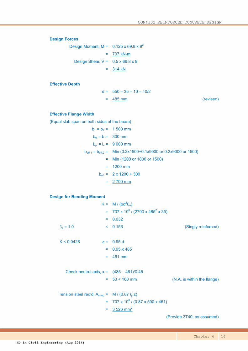
Design Forces
Design Moment, M = 0.125 x 69.8 x 92
= 707 kN-m
Design Shear, V = 0.5 x 69.8 x 9
= 314 kN
Effective Depth
d = 550 – 35 – 10 – 40/2
= 485 mm (revised)
Effective Flange Width
(Equal slab span on both sides of the beam)
b1 = b2 = 1 500 mm
bw = b = 300 mm
Lpi = L = 9 000 mm
beff,1 = beff,2 = Min (0.2x1500+0.1x9000 or 0.2x9000 or 1500)
= Min (1200 or 1800 or 1500)
= 1200 mm
beff = 2 x 1200 + 300
= 2 700 mm
Design for Bending Moment
K = M / (bd2fcu)
= 707 x 106 / (2700 x 4852 x 35)
= 0.032
βb = 1.0 < 0.156 (Singly reinforced)
K < 0.0428 z = 0.95 d
= 0.95 x 485
= 461 mm
Check neutral axis, x = (485 – 461)/0.45
= 53 < 160 mm (N.A. is within the flange)
Tension steel req'd, As,req = M / (0.87 fy z)
= 707 x 106 / (0.87 x 500 x 461)
= 3 526 mm2
(Provide 3T40, as assumed)
CON4332 REINFORCED CONCRETE DESIGN
Chapter 4 17
HD in Civil Engineering (Aug 2014)
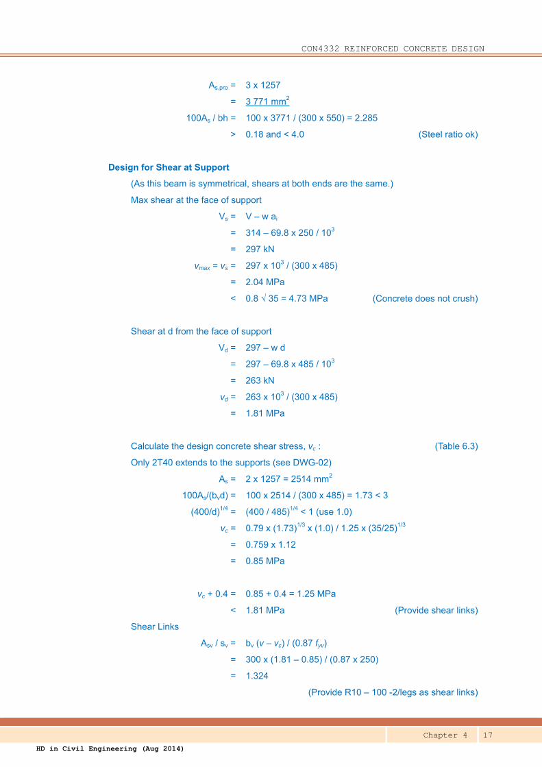
As,pro = 3 x 1257
= 3 771 mm2
100As / bh = 100 x 3771 / (300 x 550) = 2.285
> 0.18 and < 4.0 (Steel ratio ok)
Design for Shear at Support
(As this beam is symmetrical, shears at both ends are the same.)
Max shear at the face of support
Vs = V – w ai
= 314 – 69.8 x 250 / 103
= 297 kN
vmax = vs = 297 x 103 / (300 x 485)
= 2.04 MPa
< 0.8 √ 35 = 4.73 MPa (Concrete does not crush)
Shear at d from the face of support
Vd = 297 – w d
= 297 – 69.8 x 485 / 103
= 263 kN
vd = 263 x 103 / (300 x 485)
= 1.81 MPa
Calculate the design concrete shear stress, vc : (Table 6.3)
Only 2T40 extends to the supports (see DWG-02)
As = 2 x 1257 = 2514 mm2
100As/(bvd) = 100 x 2514 / (300 x 485) = 1.73 < 3
(400/d)1/4 = (400 / 485)1/4 < 1 (use 1.0)
vc = 0.79 x (1.73)1/3 x (1.0) / 1.25 x (35/25)1/3
= 0.759 x 1.12
= 0.85 MPa
vc + 0.4 = 0.85 + 0.4 = 1.25 MPa
< 1.81 MPa (Provide shear links)
Shear Links
Asv / sv = bv (v – vc) / (0.87 fyv)
= 300 x (1.81 – 0.85) / (0.87 x 250)
= 1.324
(Provide R10 – 100 -2/legs as shear links)
CON4332 REINFORCED CONCRETE DESIGN
Chapter 4 18
HD in Civil Engineering (Aug 2014)
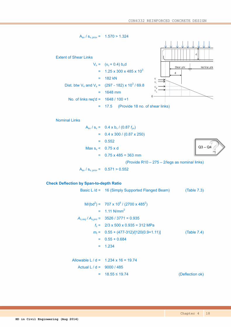
Asv / sv, prov = 1.570 > 1.324
Extent of Shear Links
Vn = (vc + 0.4) bvd
= 1.25 x 300 x 485 x 103
= 182 kN
Dist. btw Vn and Vs = (297 - 182) x 103 / 69.8
= 1648 mm
No. of links req'd = 1648 / 100 +1
= 17.5 (Provide 18 no. of shear links)
Nominal Links
Asv / sv = 0.4 x bv / (0.87 fyv)
= 0.4 x 300 / (0.87 x 250)
= 0.552
Max sv < 0.75 x d
= 0.75 x 485 = 363 mm
(Provide R10 – 275 – 2/legs as nominal links)
Asv / sv, prov = 0.571 > 0.552
Check Deflection by Span-to-depth Ratio
Basic L /d = 16 (Simply Supported Flanged Beam) (Table 7.3)
M/(bd2) = 707 x 106 / (2700 x 4852)
= 1.11 N/mm2
As,req / As,pro = 3526 / 3771 = 0.935
fs = 2/3 x 500 x 0.935 = 312 MPa
mt = 0.55 + (477-312)/[120(0.9+1.11)] (Table 7.4)
= 0.55 + 0.684
= 1.234
Allowable L / d = 1.234 x 16 = 19.74
Actual L / d = 9000 / 485
= 18.55 ≤ 19.74 (Deflection ok)
?Q3 – Q4
CON4332 REINFORCED CONCRETE DESIGN
Chapter 4 19
HD in Civil Engineering (Aug 2014)
4.2.3 Notes on Detailing
The reinforcement details of the simply-supported beams of Questions B
and C in 4.2.2 above are shown in DWG-02 at the end of the Chapter. Take
note of the following in the details:4
(a) In order to support the links, top bars are provided at the top corners
of the links. They are called carriers, and should not be regarded as
compression steel unless they are properly restrained from buckling.
(b) In theory, there is no hogging moment at the supports and therefore
top bar is not required. However, in order to avoid unsightly cracks
due partial fixity to the supporting beams, a certain amount of rebars
are provided at the top of the supports.
(c) Provision of 3 number of bars on the tension face of the beam with
300mm width, the bar spacing deems appropriate for dispersing the
cracks. (Refer to chapter 2 for details.)
(d) The maximum moment at mid-span is adopted as the design moment
to determine the reinforcement bars. The bending moment in the
beam is decreasing, theoretically, to zero at the supports and
therefore it is not necessary to have all the bottom bars extended to
the supports. The design code requires at least half of the steel be
extended to and anchored into the supports.
4.3 Continuous Beams
The design process of continuous beam is quite similar to that of
simply-supported beam except that hogging moments at supports have to
be designed for in continuous beam. For beam in building structures,
sagging moment in the mid-span is usually resisted by flanged section while
hogging moments in the supports are resisted by rectangular section.
4 The rules of reinforcement detailing are beyond the scope of this chapter. Refer to the design code for details.
CON4332 REINFORCED CONCRETE DESIGN
Chapter 4 20
HD in Civil Engineering (Aug 2014)
Three examples are provided to demonstrate the whole design process of a
continuous beam. The example in 4.3.1 demonstrates the basic principle
of the design. It is a continuous beam of approximately equal span under
uniformly distributed load, and therefore the force coefficients in 4.1.2
mentioned above can be used to determine the design forces. For
demonstration purpose, only one of the spans of the continuous beam is
designed in the example.
Questions A & B in 4.3.2 let you appreciate the design of a long-span beam
by sub-frame analysis. It accentuates the heavily reinforced sections at the
supports, and illustrates the effect of moment redistribution on the design.
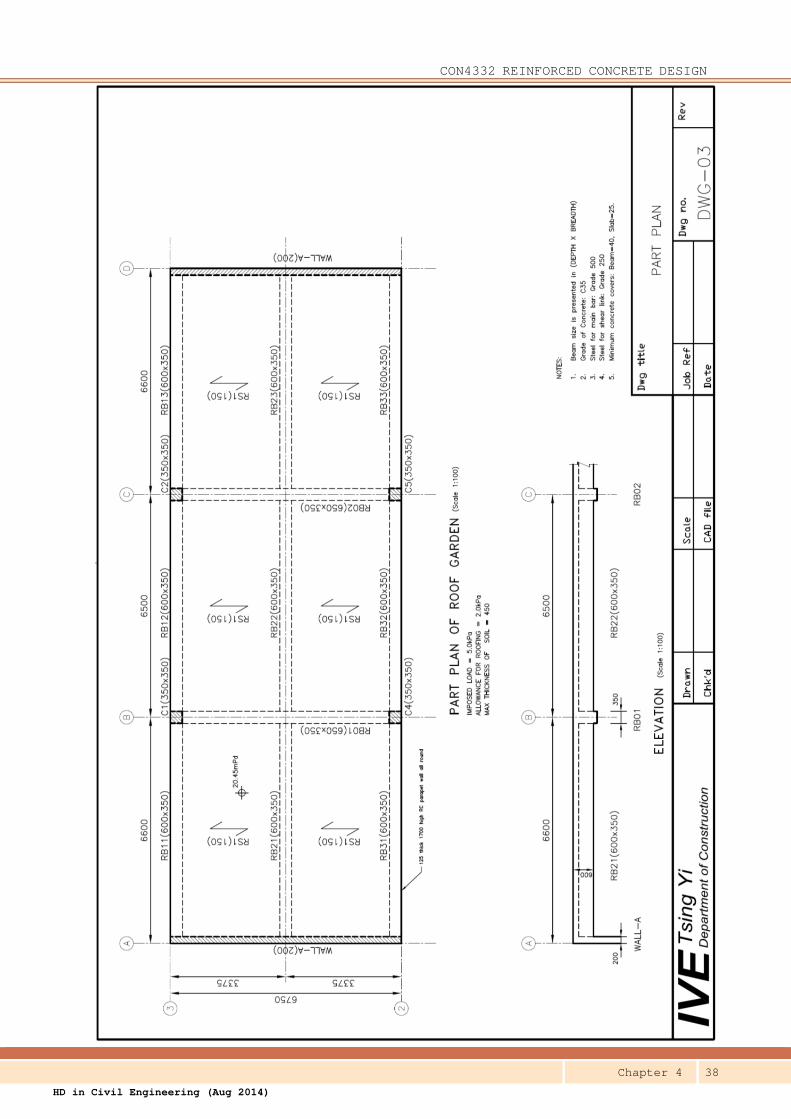
4.3.1 Example – Uniformly Loaded & Equal Span
Question DWG-03 at the end of this Chapter shows the framing plan of a roof garden. There is a
continuous beam RB21-RB22-RB23. Design the reinforcement and check the deflection
for the end span, RB21 of this beam.
Solution Design parameters
The following design parameters can be obtained from DWG-03:
Beam overall depth, h = 600 mm
Beam breadth, b = 350 mm
Slab thickness, hf = 150 mm
c/c distance btw supports = 6 500 mm (same for all spans)
Width of LHS support, Sw1 = 200 mm
Width of RHS support, Sw2 = 350 mm
c/c distance btw adjacent beams = 3 200 mm (same on both sides)
fcu = 35 MPa
fy = 500 MPa
fyv = 250 MPa
Cover = 40 mm
Preferred bar size = 32
Preferred link size = 10
Density of concrete = 24.5 kN/m3
CON4332 REINFORCED CONCRETE DESIGN
Chapter 4 21
HD in Civil Engineering (Aug 2014)
Allowance for roofing = 2.0 kPa
Allowance for soil = 450 mm thick
Characteristic imposed load = 5.0 kPa
Effective Span
As h > Sw, L = center-to-center distance btw support
= 6 500 mm
a1 = Sw1 /2 = 100 mm
a2 = Sw2 /2 = 175 mm
Loading
Load width = 3200 mm
Dead Load
Roofing: 2.0 x 3.2 = 6.4 kN/m
Soil: 20 x 0.45 x 3.2 = 28.8 kN/m
Slab S/W: 24.5 x 0.15 x 3.2 = 11.8 kN/m
Beam S/W: 24.5 x 0.35 x (0.60-0.15) = 3.9 kN/m
gk = 50.9 kN/m
Imposed Load
5.0 x 3.2 = 16.0 kN/m
qk = 16.0 kN/m
The design load, w = 1.4 x 50.9 + 1.6 x 16.0
= 96.8 kN/m
F = 96.8 x 6.5
= 629 kN
Design Forces (Table 6.1)
Design Moments
At LHS support, M = 0
At mid-span, M = 0.09 x 629 x 6.5
= 368 kN-m
At RHS support, M = - 0.11 x 629 x 6.5
= - 450 kN-m
Design Shears
At LHS support, V = 0.45 x 629
= 283 kN
CON4332 REINFORCED CONCRETE DESIGN
Chapter 4 22
HD in Civil Engineering (Aug 2014)
At RHS support, V = 0.6 x 629
= 377 kN
Design for Mid-span Bending Moment
M = 368 KN-m (sagging Mt resisted by flanged section)
Effective Depth, d = 600 – 40 – 10 – 32/2
= 534 mm
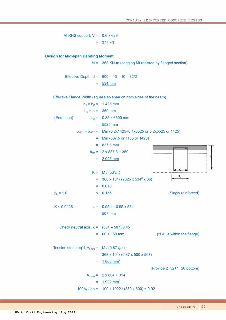
Effective Flange Width (equal slab span on both sides of the beam)
b1 = b2 = 1 425 mm
bw = b = 350 mm
(End-span) Lpi = 0.85 x 6500 mm
= 5525 mm
beff,1 = beff,2 = Min (0.2x1425+0.1x5525 or 0.2x5525 or 1425)
= Min (837.5 or 1105 or 1425)
= 837.5 mm
beff = 2 x 837.5 + 350
= 2 025 mm
K = M / (bd2fcu)
= 368 x 106 / (2025 x 5342 x 35)
= 0.018
βb = 1.0 < 0.156 (Singly reinforced)
K < 0.0428 z = 0.95d = 0.95 x 534
= 507 mm
Check neutral axis, x = (534 – 507)/0.45
= 60 < 150 mm (N.A. is within the flange)
Tension steel req'd, As,req = M / (0.87 fy z)
= 368 x 106 / (0.87 x 500 x 507)
= 1 668 mm2
(Provide 2T32+1T20 bottom)
As,pro = 2 x 804 + 314
= 1 922 mm2
100As / bh = 100 x 1922 / (350 x 600) = 0.92
bw
d
CON4332 REINFORCED CONCRETE DESIGN
Chapter 4 23
HD in Civil Engineering (Aug 2014)
> 0.18 and < 4.0 (Steel ratio ok)
Design for LHS Support Shear
(The design moment is zero.
Therefore, As and d of the bottom bars are used for shear design.)
Max shear at the face of support
Vs = V – w a1
= 283 – 96.8 x 100 / 103
= 273 kN
vmax = vs = 273 x 103 / (350 x 534)
= 1.46 MPa
< 0.8 √ 35 = 4.73 MPa (Concrete does not crush)
Shear at d from the face of support
Vd = Vs – w d
= 273 – 96.8 x 534 / 103
= 221 kN
vd = 221 x 103 / (350 x 534)
= 1.18 MPa
Calculate the design concrete shear stress, vc : (Table 6.3)
100As/(bvd) = 100 x 1922 / (350 x 534) = 1.03 < 3
(400/d)1/4 = (400 / 534)1/4 < 1 (use 1.0)
vc = 0.79 x (1.03)1/3 x (1.0) / 1.25 x (35/25)1/3
= 0.64 x 1.12
= 0.72 MPa
vc + 0.4 = 0.72 + 0.4 = 1.12 MPa
< 1.18 MPa (Shear link is required)
Shear Link
Asv / sv = bv (v – vc) / (0.87 fyv)
= 350 x (1.18 – 0.72) / (0.87 x 250)
= 0.740
Nominal Link
Asv / sv = 0.4 x bv / (0.87 fyv)
= 0.4 x 350 / (0.87 x 250)
= 0.644
Max sv < 0.75 x d
CON4332 REINFORCED CONCRETE DESIGN
Chapter 4 24
HD in Civil Engineering (Aug 2014)
bw
d
= 0.75 x 685 = 514 mm
(Provide R10 – 200 – 2/legs)
Asv / sv, prov = 0.785 > 0.644 and 0.740
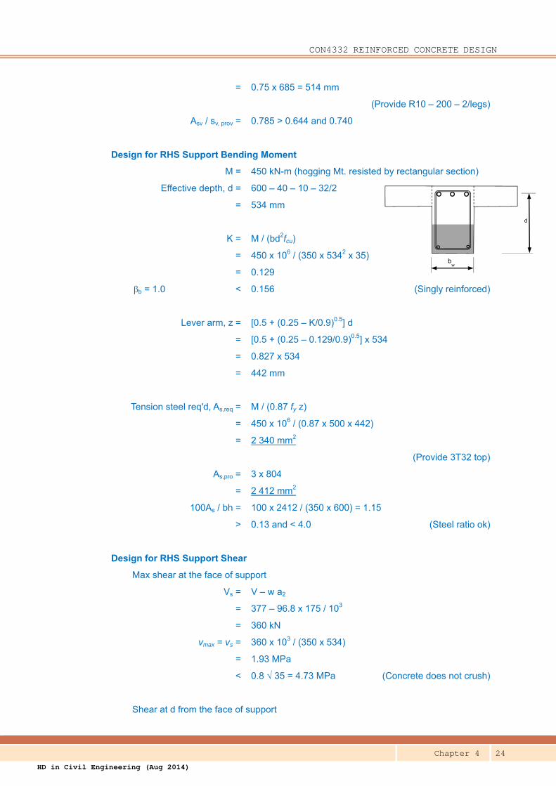
Design for RHS Support Bending Moment
M = 450 kN-m (hogging Mt. resisted by rectangular section)
Effective depth, d = 600 – 40 – 10 – 32/2
= 534 mm
K = M / (bd2fcu)
= 450 x 106 / (350 x 5342 x 35)
= 0.129
βb = 1.0 < 0.156 (Singly reinforced)
Lever arm, z = [0.5 + (0.25 – K/0.9)0.5] d
= [0.5 + (0.25 – 0.129/0.9)0.5] x 534
= 0.827 x 534
= 442 mm
Tension steel req'd, As,req = M / (0.87 fy z)
= 450 x 106 / (0.87 x 500 x 442)
= 2 340 mm2
(Provide 3T32 top)
As,pro = 3 x 804
= 2 412 mm2
100As / bh = 100 x 2412 / (350 x 600) = 1.15
> 0.13 and < 4.0 (Steel ratio ok)
Design for RHS Support Shear
Max shear at the face of support
Vs = V – w a2
= 377 – 96.8 x 175 / 103
= 360 kN
vmax = vs = 360 x 103 / (350 x 534)
= 1.93 MPa
< 0.8 √ 35 = 4.73 MPa (Concrete does not crush)
Shear at d from the face of support
CON4332 REINFORCED CONCRETE DESIGN
Chapter 4 25
HD in Civil Engineering (Aug 2014)
Vd = Vs – w d
= 360 – 96.8 x 534 / 103
= 308 kN
vd = 308 x 103 / (350 x 534)
= 1.65 MPa
Calculate the design concrete shear stress, vc : (Table 6.3)
100As/(bvd) = 100 x 2412 / (350 x 534) = 1.29 < 3
(400/d)1/4 = (400 / 534)1/4 < 1 (use 1.0)
vc = 0.79 x (1.29)1/3 x (1.0) / 1.25 x (35/25)1/3
= 0.69 x 1.12
= 0.77 MPa
vc + 0.4 = 0.77 + 0.4 = 1.17 MPa
< 1.65 MPa (Shear link is required)
Shear Link
Asv / sv = bv (v – vc) / (0.87 fyv)
= 350 x (1.65 – 0.77) / (0.87 x 250)
= 1.42
(Provide R10 – 200 -4/legs as shear link)
Asv / sv, prov = 2 x 0.785 = 1.57 > 1.42
Extent of Shear Link
Vn = (vc + 0.4) bvd
= 1.17 x 350 x 534 / 103
= 219 kN
Dist. btw Vn and Vs = (360 - 219) x 103 / 96.8
= 1457 mm
No. of link req'd = 1457 / 200 +1
= 8.3 (Provide 9 no. of shear links)
Check Deflection by Span-to-depth Ratio
Basic L /d = 18.5 (End Span of Flanged Beam) (Table 7.3)
M/(bd2) = 368 x 106 / (2025 x 5342)
= 0.637 N/mm2
As,req / As,pro = 1668 / 1922 = 0.868
fs = 2/3 x 500 x 0.868 = 289 MPa
mt = 0.55 + (477-289)/[120(0.9+0.637)] (Table 7.4)
= 0.55 + 1.019
Use mid-span
moment and steel
to check L/d ratio.
CON4332 REINFORCED CONCRETE DESIGN
Chapter 4 26
HD in Civil Engineering (Aug 2014)
= 1.569
Allowable L / d = 1.569 x 18.5 = 29.03
Actual L / d = 6500 / 534
= 12.17 ≤ 29.03 (Deflection ok)
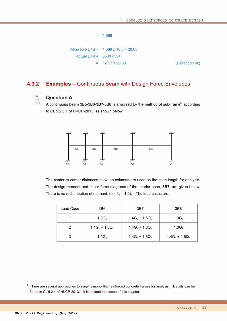
4.3.2 Examples – Continuous Beam with Design Force Envelopes
Question A A continuous beam 3B5-3B6-3B7-3B8 is analyzed by the method of sub-frame5 according
to Cl. 5.2.5.1 of HKCP-2013, as shown below.
3B5 3B6 3B7 3B8
C7 C8 C9 C1 C1
The center-to-center distances between columns are used as the span length for analysis.
The design moment and shear force diagrams of the interior span, 3B7, are given below.
There is no redistribution of moment, (i.e. βb = 1.0). The load cases are:
Load Case 3B6 3B7 3B8
1 1.0Gk 1.4Gk + 1.6Qk 1.0Gk
2 1.4Gk + 1.6Qk 1.4Gk + 1.6Qk 1.0Gk
3 1.0Gk 1.4Gk + 1.6Qk 1.4Gk + 1.6Qk
5 There are several approaches to simplify monolithic reinforced concrete frames for analysis. Details can be
found in Cl. 5.2.4 of HKCP-2013. It is beyond the scope of this chapter.
CON4332 REINFORCED CONCRETE DESIGN
Chapter 4 27
HD in Civil Engineering (Aug 2014)
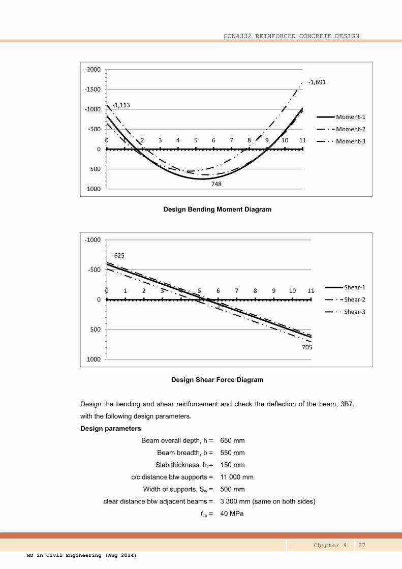
Design Bending Moment Diagram
Design Shear Force Diagram
Design the bending and shear reinforcement and check the deflection of the beam, 3B7,
with the following design parameters.
Design parameters
Beam overall depth, h = 650 mm
Beam breadth, b = 550 mm
Slab thickness, hf = 150 mm
c/c distance btw supports = 11 000 mm
Width of supports, Sw = 500 mm
clear distance btw adjacent beams = 3 300 mm (same on both sides)
fcu = 40 MPa
748
‐1,113
‐1,691
‐2000
‐1500
‐1000
‐500
0
500
1000
0 1 2 3 4 5 6 7 8 9 10 11
Moment‐1
Moment‐2
Moment‐3
17
‐625
705
‐1000
‐500
0
500
1000
0 1 2 3 4 5 6 7 8 9 10 11Shear‐1
Shear‐2
Shear‐3
CON4332 REINFORCED CONCRETE DESIGN
Chapter 4 28
HD in Civil Engineering (Aug 2014)
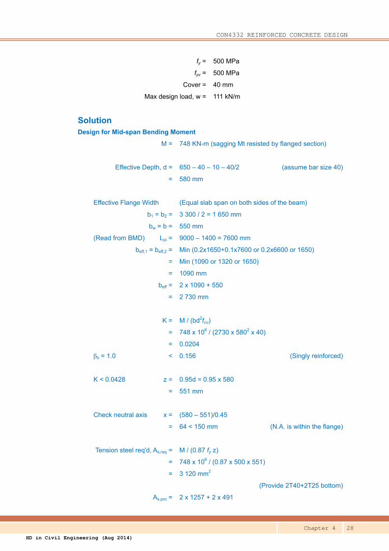
fy = 500 MPa
fyv = 500 MPa
Cover = 40 mm
Max design load, w = 111 kN/m
Solution Design for Mid-span Bending Moment
M = 748 KN-m (sagging Mt resisted by flanged section)
Effective Depth, d = 650 – 40 – 10 – 40/2 (assume bar size 40)
= 580 mm
Effective Flange Width (Equal slab span on both sides of the beam)
b1 = b2 = 3 300 / 2 = 1 650 mm
bw = b = 550 mm
(Read from BMD) Lpi = 9000 – 1400 = 7600 mm
beff,1 = beff,2 = Min (0.2x1650+0.1x7600 or 0.2x6600 or 1650)
= Min (1090 or 1320 or 1650)
= 1090 mm
beff = 2 x 1090 + 550
= 2 730 mm
K = M / (bd2fcu)
= 748 x 106 / (2730 x 5802 x 40)
= 0.0204
βb = 1.0 < 0.156 (Singly reinforced)
K < 0.0428 z = 0.95d = 0.95 x 580
= 551 mm
Check neutral axis x = (580 – 551)/0.45
= 64 < 150 mm (N.A. is within the flange)
Tension steel req'd, As,req = M / (0.87 fy z)
= 748 x 106 / (0.87 x 500 x 551)
= 3 120 mm2
(Provide 2T40+2T25 bottom)
As,pro = 2 x 1257 + 2 x 491
CON4332 REINFORCED CONCRETE DESIGN
Chapter 4 29
HD in Civil Engineering (Aug 2014)
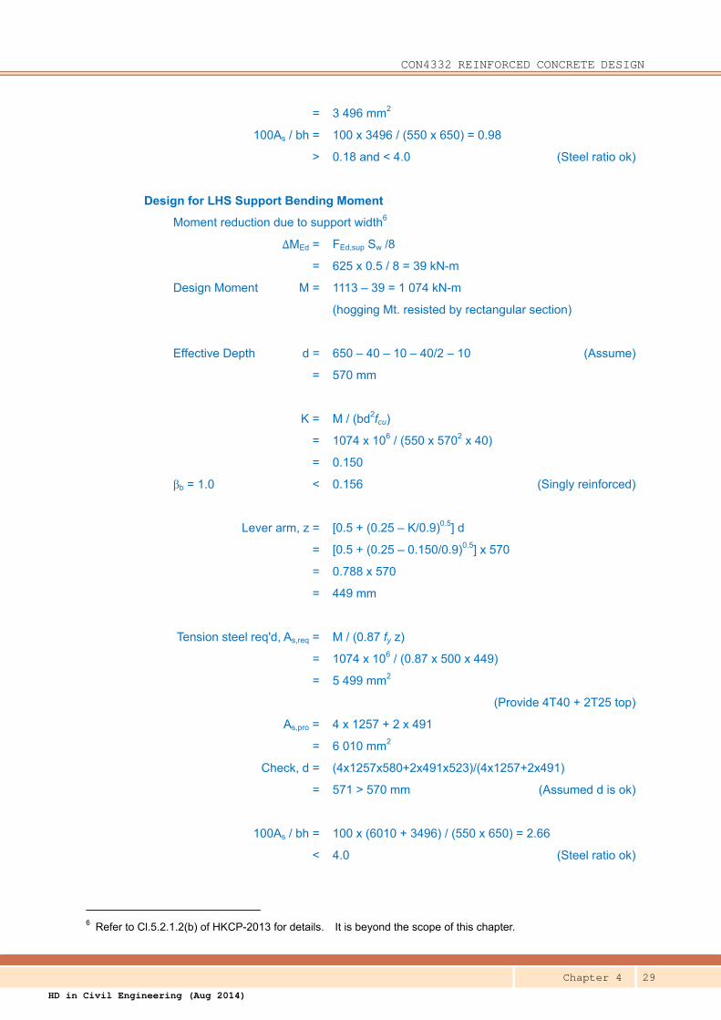
= 3 496 mm2
100As / bh = 100 x 3496 / (550 x 650) = 0.98
> 0.18 and < 4.0 (Steel ratio ok)
Design for LHS Support Bending Moment
Moment reduction due to support width6
ΔMEd = FEd,sup Sw /8
= 625 x 0.5 / 8 = 39 kN-m
Design Moment M = 1113 – 39 = 1 074 kN-m
(hogging Mt. resisted by rectangular section)
Effective Depth d = 650 – 40 – 10 – 40/2 – 10 (Assume)
= 570 mm
K = M / (bd2fcu)
= 1074 x 106 / (550 x 5702 x 40)
= 0.150
βb = 1.0 < 0.156 (Singly reinforced)
Lever arm, z = [0.5 + (0.25 – K/0.9)0.5] d
= [0.5 + (0.25 – 0.150/0.9)0.5] x 570
= 0.788 x 570
= 449 mm
Tension steel req'd, As,req = M / (0.87 fy z)
= 1074 x 106 / (0.87 x 500 x 449)
= 5 499 mm2
(Provide 4T40 + 2T25 top)
As,pro = 4 x 1257 + 2 x 491
= 6 010 mm2
Check, d = (4x1257x580+2x491x523)/(4x1257+2x491)
= 571 > 570 mm (Assumed d is ok)
100As / bh = 100 x (6010 + 3496) / (550 x 650) = 2.66
< 4.0 (Steel ratio ok)
6 Refer to Cl.5.2.1.2(b) of HKCP-2013 for details. It is beyond the scope of this chapter.
CON4332 REINFORCED CONCRETE DESIGN
Chapter 4 30
HD in Civil Engineering (Aug 2014)
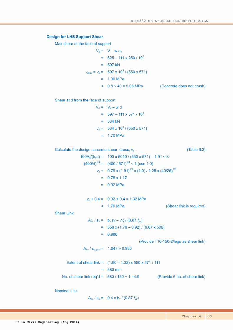
Design for LHS Support Shear
Max shear at the face of support
Vs = V – w a1
= 625 – 111 x 250 / 103
= 597 kN
vmax = vs = 597 x 103 / (550 x 571)
= 1.90 MPa
< 0.8 √ 40 = 5.06 MPa (Concrete does not crush)
Shear at d from the face of support
Vd = Vs – w d
= 597 – 111 x 571 / 103
= 534 kN
vd = 534 x 103 / (550 x 571)
= 1.70 MPa
Calculate the design concrete shear stress, vc : (Table 6.3)
100As/(bvd) = 100 x 6010 / (550 x 571) = 1.91 < 3
(400/d)1/4 = (400 / 571)1/4 < 1 (use 1.0)
vc = 0.79 x (1.91)1/3 x (1.0) / 1.25 x (40/25)1/3
= 0.78 x 1.17
= 0.92 MPa
vc + 0.4 = 0.92 + 0.4 = 1.32 MPa
< 1.70 MPa (Shear link is required)
Shear Link
Asv / sv = bv (v – vc) / (0.87 fyv)
= 550 x (1.70 – 0.92) / (0.87 x 500)
= 0.986
(Provide T10-150-2/legs as shear link)
Asv / sv, pro = 1.047 > 0.986
Extent of shear link = (1.90 – 1.32) x 550 x 571 / 111
= 580 mm
No. of shear link req'd = 580 / 150 + 1 =4.9 (Provide 6 no. of shear link)
Nominal Link
Asv / sv = 0.4 x bv / (0.87 fyv)
CON4332 REINFORCED CONCRETE DESIGN
Chapter 4 31
HD in Civil Engineering (Aug 2014)
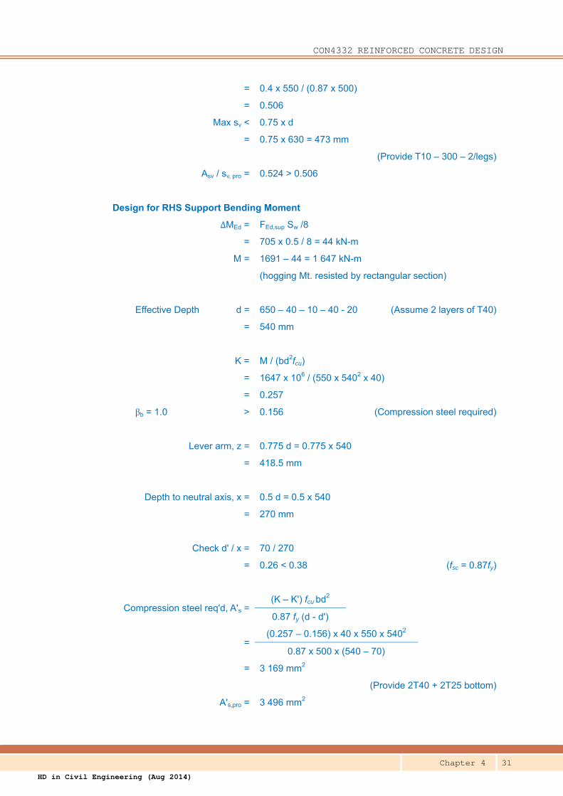
= 0.4 x 550 / (0.87 x 500)
= 0.506
Max sv < 0.75 x d
= 0.75 x 630 = 473 mm
(Provide T10 – 300 – 2/legs)
Asv / sv, pro = 0.524 > 0.506
Design for RHS Support Bending Moment
ΔMEd = FEd,sup Sw /8
= 705 x 0.5 / 8 = 44 kN-m
M = 1691 – 44 = 1 647 kN-m
(hogging Mt. resisted by rectangular section)
Effective Depth d = 650 – 40 – 10 – 40 - 20 (Assume 2 layers of T40)
= 540 mm
K = M / (bd2fcu)
= 1647 x 106 / (550 x 5402 x 40)
= 0.257
βb = 1.0 > 0.156 (Compression steel required)
Lever arm, z = 0.775 d = 0.775 x 540
= 418.5 mm
Depth to neutral axis, x = 0.5 d = 0.5 x 540
= 270 mm
Check d' / x = 70 / 270
= 0.26 < 0.38 (fsc = 0.87fy)
Compression steel req'd, A's =(K – K') fcu bd2
0.87 fy (d - d')
=(0.257 – 0.156) x 40 x 550 x 5402
0.87 x 500 x (540 – 70)
= 3 169 mm2
(Provide 2T40 + 2T25 bottom)
A's,pro = 3 496 mm2
CON4332 REINFORCED CONCRETE DESIGN
Chapter 4 32
HD in Civil Engineering (Aug 2014)
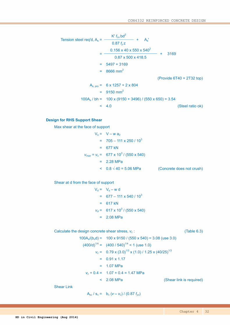
Tension steel req'd, As =K' fcu bd2
+ As' 0.87 fy z
=0.156 x 40 x 550 x 5402
+ 3169 0.87 x 500 x 418.5
= 5497 + 3169
= 8666 mm2
(Provide 6T40 + 2T32 top)
As, pro = 6 x 1257 + 2 x 804
= 9150 mm2
100As / bh = 100 x (9150 + 3496) / (550 x 650) = 3.54
< 4.0 (Steel ratio ok)
Design for RHS Support Shear
Max shear at the face of support
Vs = V – w a2
= 705 – 111 x 250 / 103
= 677 kN
vmax = vs = 677 x 103 / (550 x 540)
= 2.28 MPa
< 0.8 √ 40 = 5.06 MPa (Concrete does not crush)
Shear at d from the face of support
Vd = Vs – w d
= 677 – 111 x 540 / 103
= 617 kN
vd = 617 x 103 / (550 x 540)
= 2.08 MPa
Calculate the design concrete shear stress, vc : (Table 6.3)
100As/(bvd) = 100 x 9150 / (550 x 540) = 3.08 (use 3.0)
(400/d)1/4 = (400 / 540)1/4 < 1 (use 1.0)
vc = 0.79 x (3.0)1/3 x (1.0) / 1.25 x (40/25)1/3
= 0.91 x 1.17
= 1.07 MPa
vc + 0.4 = 1.07 + 0.4 = 1.47 MPa
< 2.08 MPa (Shear link is required)
Shear Link
Asv / sv = bv (v – vc) / (0.87 fyv)

CON4332 REINFORCED CONCRETE DESIGN
Chapter 4 33
HD in Civil Engineering (Aug 2014)
= 550 x (2.08 – 1.07) / (0.87 x 500)
= 1.277
(Provide T10 – 225 -4/legs as shear link)
Asv / sv, pro = 2 x 0.698 = 1.396 > 1.277
Extent of shear link = (2.28 - 1.47) x 550 x 540 / 111
= 2167 mm
No. of link req'd = 2167 / 225 +1 = 10.6 (Provide 11 no. of shear links)
(These shear links also provide restraint to bottom compression bars)
Nominal Link (Same as above) (Provide T10 – 300 – 2/legs)
Check Deflection by Span-to-depth Ratio
Basic L /d = 21 (Continuous of Flanged Beam) (Table 7.3)
L > 10m ml = 10/11 = 0.91
M/(bd2) = 748 x 106 / (2530 x 5802)
= 0.879 N/mm2
As,req / As,pro = 3120 / 3496 = 0.892
fs = 2/3 x 500 x 0.892 = 297 MPa
mt = 0.55 + (477-297)/[120(0.9+0.879)] (Table 7.4)
= 0.55 + 0.843
= 1.393
Allowable L / d = 0.91 x 1.393 x 21 = 26.6
Actual L / d = 11000 / 580
= 19.0 ≤ 26.6 (Deflection ok)
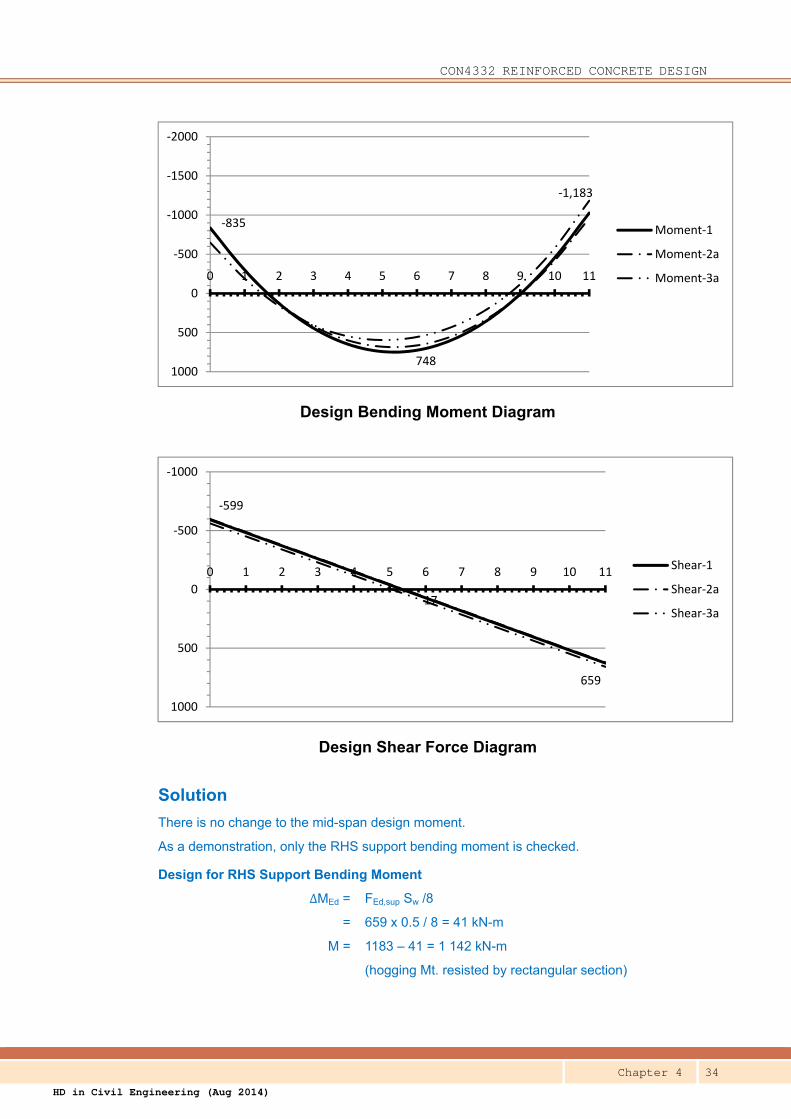
Question B Moment redistribution is applied to the design moments at the supports of the beam 3B7.
The RHS support moment of load case 2 is redistributed by 25% and the LHS support
moment of load case 3 is redistributed by 30% and the resultant design moment and shear
diagrams are given below. The design parameters in Example A are still applicable.
Re-design the beam 3B7.
CON4332 REINFORCED CONCRETE DESIGN
Chapter 4 34
HD in Civil Engineering (Aug 2014)
Design Bending Moment Diagram
Design Shear Force Diagram
Solution
There is no change to the mid-span design moment.
As a demonstration, only the RHS support bending moment is checked.
Design for RHS Support Bending Moment
ΔMEd = FEd,sup Sw /8
= 659 x 0.5 / 8 = 41 kN-m
M = 1183 – 41 = 1 142 kN-m
(hogging Mt. resisted by rectangular section)
748
‐835
‐1,183
‐2000
‐1500
‐1000
‐500
0
500
1000
0 1 2 3 4 5 6 7 8 9 10 11
Moment‐1
Moment‐2a
Moment‐3a
17
‐599
659
‐1000
‐500
0
500
1000
0 1 2 3 4 5 6 7 8 9 10 11Shear‐1
Shear‐2a
Shear‐3a
CON4332 REINFORCED CONCRETE DESIGN
Chapter 4 35
HD in Civil Engineering (Aug 2014)
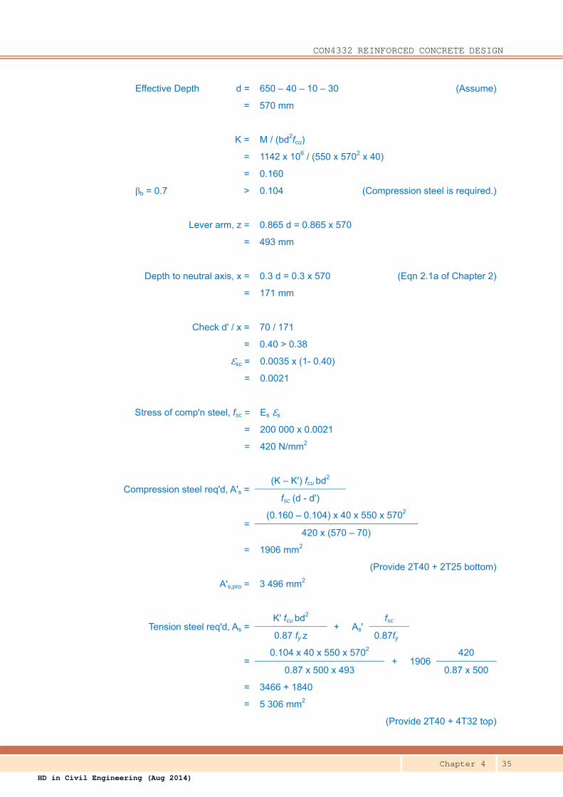
Effective Depth d = 650 – 40 – 10 – 30 (Assume)
= 570 mm
K = M / (bd2fcu)
= 1142 x 106 / (550 x 5702 x 40)
= 0.160
βb = 0.7 > 0.104 (Compression steel is required.)
Lever arm, z = 0.865 d = 0.865 x 570
= 493 mm
Depth to neutral axis, x = 0.3 d = 0.3 x 570 (Eqn 2.1a of Chapter 2)
= 171 mm
Check d' / x = 70 / 171
= 0.40 > 0.38
Ɛsc = 0.0035 x (1- 0.40)
= 0.0021
Stress of comp'n steel, fsc = Es Ɛs
= 200 000 x 0.0021
= 420 N/mm2
Compression steel req'd, A's =(K – K') fcu bd2
fsc (d - d')
=(0.160 – 0.104) x 40 x 550 x 5702
420 x (570 – 70)
= 1906 mm2
(Provide 2T40 + 2T25 bottom)
A's,pro = 3 496 mm2
Tension steel req'd, As =K' fcu bd2
+ As' fsc
0.87 fy z 0.87fy
=0.104 x 40 x 550 x 5702
+ 1906 420
0.87 x 500 x 493 0.87 x 500
= 3466 + 1840
= 5 306 mm2
(Provide 2T40 + 4T32 top)
CON4332 REINFORCED CONCRETE DESIGN
Chapter 4 36
HD in Civil Engineering (Aug 2014)
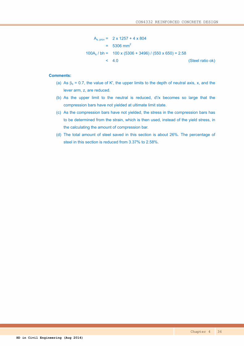
As, prov = 2 x 1257 + 4 x 804
= 5306 mm2
100As / bh = 100 x (5306 + 3496) / (550 x 650) = 2.58
< 4.0 (Steel ratio ok)
Comments:
(a) As βb = 0.7, the value of K', the upper limits to the depth of neutral axis, x, and the
lever arm, z, are reduced.
(b) As the upper limit to the neutral is reduced, d'/x becomes so large that the
compression bars have not yielded at ultimate limit state.
(c) As the compression bars have not yielded, the stress in the compression bars has
to be determined from the strain, which is then used, instead of the yield stress, in
the calculating the amount of compression bar.
(d) The total amount of steel saved in this section is about 26%. The percentage of
steel in this section is reduced from 3.37% to 2.58%.
CON4332 REINFORCED CONCRETE DESIGN
Chapter 4 37
HD in Civil Engineering (Aug 2014)
CON4332 REINFORCED CONCRETE DESIGN
Chapter 4 38
HD in Civil Engineering (Aug 2014)
CON4332 REINFORCED CONCRETE DESIGN
Chapter 4 39
HD in Civil Engineering (Aug 2014)
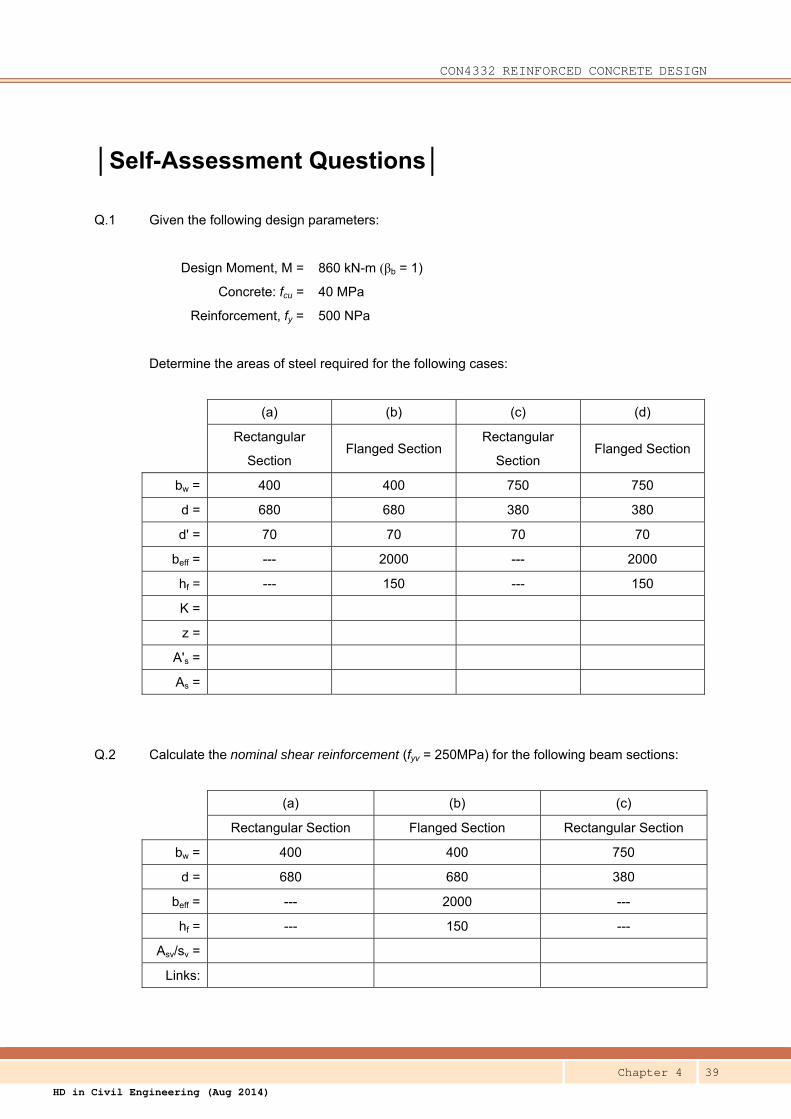
│Self-Assessment Questions│
Q.1 Given the following design parameters:
Design Moment, M = 860 kN-m (βb = 1)
Concrete: fcu = 40 MPa
Reinforcement, fy = 500 NPa
Determine the areas of steel required for the following cases:
(a) (b) (c) (d)
Rectangular
Section Flanged Section
Rectangular
Section Flanged Section
bw = 400 400 750 750
d = 680 680 380 380
d' = 70 70 70 70
beff = --- 2000 --- 2000
hf = --- 150 --- 150
K =
z =
A's =
As =
Q.2 Calculate the nominal shear reinforcement (fyv = 250MPa) for the following beam sections:
(a) (b) (c)
Rectangular Section Flanged Section Rectangular Section
bw = 400 400 750
d = 680 680 380
beff = --- 2000 ---
hf = --- 150 ---
Asv/sv =
Links:
CON4332 REINFORCED CONCRETE DESIGN
Chapter 4 40
HD in Civil Engineering (Aug 2014)
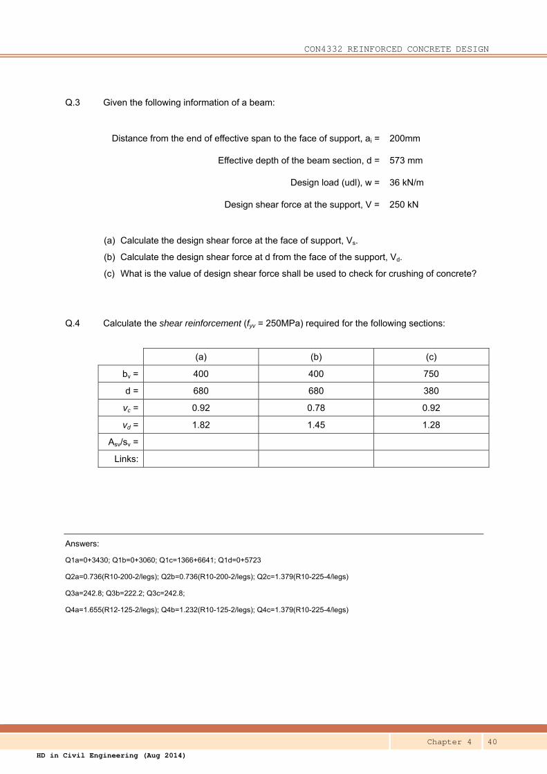
Q.3 Given the following information of a beam:
Distance from the end of effective span to the face of support, ai = 200mm
Effective depth of the beam section, d = 573 mm
Design load (udl), w = 36 kN/m
Design shear force at the support, V = 250 kN
(a) Calculate the design shear force at the face of support, Vs.
(b) Calculate the design shear force at d from the face of the support, Vd.
(c) What is the value of design shear force shall be used to check for crushing of concrete?
Q.4 Calculate the shear reinforcement (fyv = 250MPa) required for the following sections:
(a) (b) (c)
bv = 400 400 750
d = 680 680 380
vc = 0.92 0.78 0.92
vd = 1.82 1.45 1.28
Asv/sv =
Links:
Answers:
Q1a=0+3430; Q1b=0+3060; Q1c=1366+6641; Q1d=0+5723
Q2a=0.736(R10-200-2/legs); Q2b=0.736(R10-200-2/legs); Q2c=1.379(R10-225-4/legs)
Q3a=242.8; Q3b=222.2; Q3c=242.8;
Q4a=1.655(R12-125-2/legs); Q4b=1.232(R10-125-2/legs); Q4c=1.379(R10-225-4/legs)
CON4332 REINFORCED CONCRETE DESIGN
Chapter 4 41
HD in Civil Engineering (Aug 2014)
│Tutorial Questions│
AQ1 The design parameters, including loading, span, beam size, etc. of the
beams in the examples in 4.2.1 and 4.2.2 are quite similar.
(a) Identify their similarities.
(b) Identify the differences in their design process.
(c) Identify and discuss the differences in the result.
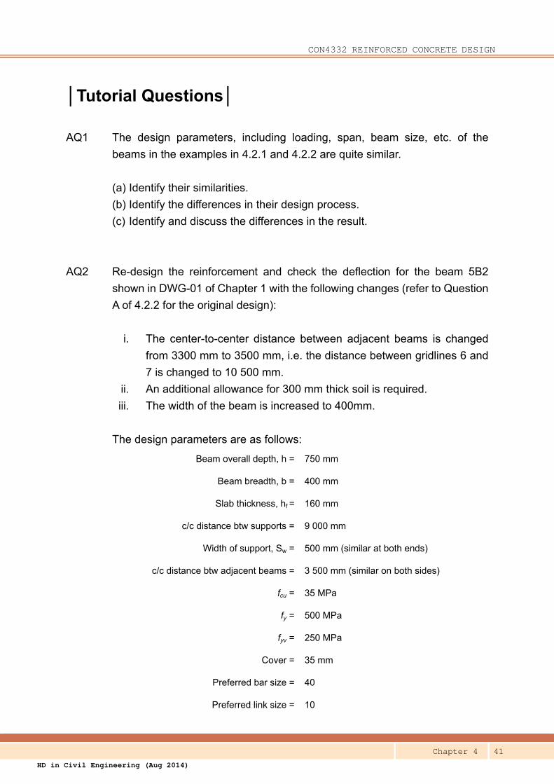
AQ2 Re-design the reinforcement and check the deflection for the beam 5B2
shown in DWG-01 of Chapter 1 with the following changes (refer to Question
A of 4.2.2 for the original design):
i. The center-to-center distance between adjacent beams is changed
from 3300 mm to 3500 mm, i.e. the distance between gridlines 6 and
7 is changed to 10 500 mm.
ii. An additional allowance for 300 mm thick soil is required.
iii. The width of the beam is increased to 400mm.
The design parameters are as follows:
Beam overall depth, h = 750 mm
Beam breadth, b = 400 mm
Slab thickness, hf = 160 mm
c/c distance btw supports = 9 000 mm
Width of support, Sw = 500 mm (similar at both ends)
c/c distance btw adjacent beams = 3 500 mm (similar on both sides)
fcu = 35 MPa
fy = 500 MPa
fyv = 250 MPa
Cover = 35 mm
Preferred bar size = 40
Preferred link size = 10
CON4332 REINFORCED CONCRETE DESIGN
Chapter 4 42
HD in Civil Engineering (Aug 2014)
Allowance for finishes = 2.0 kPa
Soil thickness = 300 mm
Characteristic imposed load = 5.0 kPa
AQ3 Design the reinforcement and check the deflection for the interior span,
RB22, of the continuous beam in 4.3.1, and as shown in DWG-03. Adopt
the design parameters in 4.3.1.